Embed Size (px)
Citation preview

Cequent™ Performance Products, Inc. www.cequentgroup.com Technical Assistance: 800-632-3290 [email protected]
Installation Instructions PART NUMBERS: 75214, 87684, 44766
©2015 Cequent™ Performance Products, Inc. - Printed in Mexico Sheet 1 of 18 75214NP 6-11-15 Rev. B
To prevent SERIOUS INJURY, DEATH or PROPERTY DAMAGE:
• ALWAYS read, understand and follow warnings and instructions
for your hitch BEFORE installation. Keep for future reference.
• DO NOT cut, weld or modify this receiver.
• CHECK all fasteners are tight and your hitch is securely mounted
to your vehicle periodically.
• ALWAYS read, understand and follow all warnings and
instructions for your vehicle and for other accessories you will use
with your hitch BEFORE use.
• LOAD the trailer heavier in front.
• DO NOT exceed lower of towing vehicle manufacturer’s rating or:
• ALWAYS wear your seatbelt.
• SLOW DOWN when towing, NEVER exceed any posted speed limit.
• If EXCESS SWAY occurs, take your foot off the gas pedal and hold
the steering wheel as steady as possible. DO NOT apply your
brakes and DO NOT speed up.
Hitch Type Max Gross Trailer Weight
Max Tongue Weight
Weight Carrying 4000 lb. (1816 kg) 600 lb. (272 kg)
Weight Distributing 4000 lb. (1816 kg) 600 lb. (272 kg)
Scan for safe towing tip, or visit http://www.cequentgroup.com/qr-product.aspx
LIMITED LIFETIME WARRANTY
1. Limited Lifetime Warranty (“Warranty”). Cequent Performance Products, Inc. ("We",
“Us” or “Our”) warrants to the original consumer purchaser only ("You" or “Your”) that the
product will be free from material defects in both material and workmanship, ordinary wear
and tear excepted. The Warranty is valid only if (a) the products are returned to Us for
inspection and testing; (b) Our inspection discloses to Our satisfaction that any alleged
nonconformance are material and have not been caused by misuse, neglect, wear and tear,
improper installation, unsuitable storage, improper repair, alteration, or accident; and (c) the
products were installed, maintained and used in accordance with Our instructions. THE
WARRANTY IS MADE IN LIEU OF ALL OTHER WARRANTIES, EXPRESS OR
IMPLIED (OTHER THAN THE WARRANTY OF TITLE AS PROVIDED BY THE
UNIFORM COMMERCIAL CODE IN EFFECT IN MICHIGAN), INCLUDING
WITHOUT LIMITATION, ANY WARRANTIES OF MERCHANTABILITY OR FITNESS
FOR A PARTICULAR PURPOSE, SAID WARRANTIES BEING EXPRESSLY
DISCLAIMED.
2. Obligations of Purchaser. To make a Warranty claim, contact Us at our principal address of
47912 Halyard Drive, Suite 100, Plymouth, MI 48170, 1-800-632-3290, identify the product
by model number, and follow the claim instructions that will be provided. Any returned
product that is replaced by Us becomes our property. You may be responsible for return
shipping costs. Please retain your purchase receipt to verify date of purchase and that You
are the original consumer purchaser. The product and the purchase receipt must be provided
to Us in order to process Your Warranty claim.
3. Exclusive Remedy. Product replacement is Your sole and exclusive remedy under this
Warranty. We shall not be liable for service or labor charges incurred in removing or
replacing a product. IN NO EVENT WILL WE BE RESPONSIBLE FOR ANY INDIRECT,
SPECIAL, CONSEQUENTIAL OR PUNITIVE DAMAGES.
4. Assumption of Risk. You acknowledge and agree that any use of the product for any
purpose other than the specified use(s) stated in the product instructions is at Your own risk.
5. Governing Law. This Warranty gives You specific legal rights, and You also may have
other rights which vary from state to state. This Warranty is governed by the laws of the
State of Michigan, without regard to rules pertaining to conflicts of law. The state courts
located in Oakland County, Michigan shall have exclusive jurisdiction for any disputes
relating to this Warranty.
Rev 9/2014

Cequent™ Performance Products, Inc. www.cequentgroup.com Technical Assistance: 800-632-3290 [email protected]
Installation Instructions PART NUMBERS: 75214, 87684, 44766
Applications:
Years Make Models 2015-Current* Ford Edge
*Visit our website for the most up to date information regarding application years and trim levels.
Equipment Required:
Ratchet Torque Wrench
Safety Glasses
Sockets
5.5 mm 10 mm 3 / 4 ‘’
Flat Head Screw
Driver
DO NOT EXCEED LOWER OF TOWING VEHICLE MANUFACTURER’S RATING OR:
Hitch Type Max Gross Trailer Weight Max Tongue Weight
Weight Carrying 4000 lb. (1816 kg) 600 lb. (272 kg)
Weight Distributing 4000 lb. (1816 kg) 600 lb. (272 kg)
Representative Vehicle Photo
©2015 Cequent™ Performance Products, Inc. - Printed in Mexico Sheet 2 of 18 75214NP 6-11-15 Rev. B
Installation Time: 30 min. The time listed above is the average time for professional installers. If you do not feel comfortable performing this installation on your own or are in need of assistance, please contact a professional installer.
Accessory Rating
Visit www.hitchmatch.net for more information on
hitch match
Hitch Illustration
Front of Vehicle
Utility Knife
Lubricant or Soapy water
Marker Tape Measure
File

1. Remove appearance panels on both side near the wheel well and covering the frame rails, remove (2) hex nuts (M10 socket) on bottom of the frame rail and (2) hex nuts with a (M5.5 socket) at the bottom of the frame rail. Both sides. Will need to trim or remove once hitch is in place.
2. Lower the exhaust at the rubber isolators on both sides of the exhaust. Support the exhaust to prevent damage to the vehicle. Note: Spraying a lubricant or soapy water on the metal hanger rod and the rubber isolator helps removal.
3. Feed the coiled end of the pull wire through rearward hole and out the access hole. Attach spacer and carriage bolt onto pull wire and feed the fasteners into location through the hole. Leave pull wires attached. Repeat the same process on the both frame rails. Note: it may be easier to install the carriage bolt head first. Repeat with the forward holes. Both frame rails. Note: carriage bolt tight fit into access hole may be necessary to use a file or wrench to open access hole . See figure 3.
4. Pull the pull wire with fasteners into location through the hole. Leave pull wires attached. Repeat the same process on both frame rails. Push the fasteners back into the frame rails with the pull wire attached, to allow the hitch to go into position. See figure 2
5. Raise the hitch into position, feeding the end of the pull through the holes in the hitch. Then pull the fasteners back through the frame rails and hitch brackets. Repeat the same process on both frame rails. 6. Feed conical washer over pull wire, using the washer to hold the bolt in place remove the pull wires and attach the hex nut. Tighten to hold hitch in place, repeat with all fasteners. 7. Hitch will tend to slant at a slight angle downward, push hitch straight up into frame and tighten hitch. 8. Tighten all ½-13 GR5 fasteners with torque wrench to 75 Lb.-Ft. (102 N*M) 9. Raise exhaust back into position, spraying a lubricant or soapy water on the metal hanger rod. Working on one side at a time. Note: the entire rubber isolator can move on the metal rod to re-install the exhaust it
will be necessary to push the rubber isolator toward the outside, while attaching the remaining metal rod back into position. 10. Trim appearance panel removed in step 1 or return to owner. Obtain owner permission before trimming. With the marker mark out the area to be trimmed, then using the utility knife trim the area. See figure 4.
Re-install appearance panel
©2015 Cequent™ Performance Products, Inc. - Printed in Mexico Sheet 3 of 18 75214NP 6-11-15 Rev. B
Note: check hitch frequently, making sure all fasteners and ball are properly tightened. If hitch is removed, plug all holes in trunk pan or other body panels to prevent entry of water and exhaust fumes. A hitch or ball which has been damaged should be removed and replaced. Observe safety precautions when working beneath a vehicle and wear eye protection. Do not cut access or attachment holes with a torch.
This product complies with safety specifications and requirements for connecting devices and towing systems of the state of New York, V.E.S.C. Regulation V-5 and SAE J684.
Figure 2
① Qty. (4) Carriage bolt ½-13 x 1.75 GR5
② Qty. (4)
Spacer .250 x 1 x 3
③ Qty. (4)
Conical washer ½’’
④ Qty. (4)
Het Nut ½ -13 GR2
⑤ Qty. (4)
Pull wire ½-13
Rear
Scan for step by step PHOTO installation instruction or visit
http://www.cequentgroup.com/qr-product.aspx
Fastener Kit: 75214 F
2’’
3’’
Figure 1
Installation Instructions PART NUMBERS: 75214, 87684, 44766
Proper torque is needed to keep the hitch secure to the vehicle when towing.
Always wear SAFETY GLASSES when installing hitch
①
②
③ ④
⑤
Teeth side against
hitch
Frame rails
Kink Pull wire to keep spacer
independent of bolt
Example of pull wire procedure
Access Hole
File
Wrench
Figure 3
Note: Fasteners typical both sides
2” [50.8]
6” [152.4]
Oblong access hole
Figure 4
Panel trim

©2015 Cequent™ Performance Products, Inc. - Printed in Mexico Sheet 4 of 18 75214NP 6-11-15 Rev. B
1. Remove appearance panels on both side near the wheel well and covering the frame rails, remove (2) hex nuts (M10 socket) on bottom of the frame rail and (2) hex nuts with a (M5.5 socket) at the bottom of the frame rail. Both sides. Will need to trim or remove once hitch is in place.
2. Lower the exhaust at the rubber isolators on both sides of the exhaust. Support the exhaust to prevent damage to the vehicle. Note: Spraying a lubricant or soapy water on the metal hanger rod and the rubber isolator helps removal.
3. Feed the coiled end of the pull wire through rearward hole and out the access hole. Attach spacer and carriage bolt onto pull wire and feed the fasteners into location through the hole. Leave pull wires attached. Repeat the same process on the both frame rails. Note: it may be easier to install the carriage bolt head first. Repeat with the forward holes. Both frame rails. Note: carriage bolt tight fit into access hole may be necessary to use a file or wrench to open access hole . See figure 3.
4. Pull the pull wire with fasteners into location through the hole. Leave pull wires attached. Repeat the same process on both frame rails. Push the fasteners back into the frame rails with the pull wire attached, to allow the hitch to go into position. See figure 2
Access Hole

©2015 Cequent™ Performance Products, Inc. - Printed in Mexico Sheet 5 of 18 75214NP 6-11-15 Rev. B
5. Raise the hitch into position, feeding the end of the pull through the holes in the hitch. Then pull the fasteners back through the frame rails and hitch brackets. Repeat the same process on both frame rails.
6. Feed conical washer over pull wire, using the washer to hold the bolt in place remove the pull wires and attach the hex nut. Tighten to hold hitch in place, repeat with all fasteners.
7. Hitch will tend to slant at a slight angle downward, push hitch straight up into frame and tighten hitch.
8. Tighten all ½-13 GR5 fasteners with torque wrench to 75 Lb.-Ft. (102 N*M)
Proper torque is needed to keep the hitch secure to the vehicle when towing.

©2015 Cequent™ Performance Products, Inc. - Printed in Mexico Sheet 6 of 18 75214NP 6-11-15 Rev. B
9. Raise exhaust back into position, spraying a lubricant or soapy water on the metal hanger rod. Working on one side at a time. Note: the entire rubber isolator can move on the metal rod to re-install the exhaust it will be necessary to push the rubber isolator toward the outside, while attaching the remaining metal rod back into position.
10. Trim appearance panel removed in step 1 or return to owner. Obtain owner permission before trimming.
Re-install appearance panel
2” [50.8]
6” [152.4]
Panel trim
Flat Head Screw
Driver
With the marker mark out the area to be trimmed, then using the Utility Knife trim the area.

Cequent™ Performance Products, Inc. www.cequentgroup.com Assistance technique : 800-632-3290 [email protected]
Instructions d’installation NUMÉROS DE PIÈCES :75214, 87684, 44766
©2015 Cequent™ Performance Products, Inc. - Imprimé au Mexique Feuille 7 de 18 75214NP 6-11-15 Rev. B
Pour prévenir les BLESSURES SÉVÈRES, FATALES ou les DOMMAGES
MATÉRIELS :
• TOUJOURS lire, assimiler et observer les avertissements et les instructions relatives à l'attelage AVANT d'installer celui-ci. Conserver la documentation pour référence ultérieure.
• NE PAS découper, percer, souder ni modifier cet attelage-récepteur.
• S'ASSURER régulièrement que toute la visserie est correctement serrée et que l'attelage est monté sur le véhicule en toute sécurité.
• TOUJOURS lire, assimiler et observer tous les avertissements et toutes les instructions relatives au véhicule et aux autres accessoires utilisés avec l'attelage AVANT l'utilisation.
• PLACER les plus lourdes charges à l'avant de la remorque. • NE PAS excéder les spécifications de charge du fabricant du
véhicule, ni la moins élevée des valeurs suivantes :
• TOUJOURS porter la ceinture de sécurité. • RALENTIR lors du remorquage, ne JAMAIS dépasser la limite de
vitesse signalée. • En cas de BALANCEMENT EXCESSIF, retirer le pied de la pédale
d'accélérateur et maintenir le volant aussi stable que possible. NE PAS appliquer les freins NI accélérer.
Type d'attelage Poids brut max. de la remorque
Poids max. au timon
Sans répartition de charge
4000 lb. (1816 kg) 600 lb. (272 kg)
Répartition de charge 4000 lb. (1816 kg) 600 lb. (272 kg)
Numérisez pour des conseils de sécurité, ou visitez http://www.cequentgroup.com/qr-product.aspx
GARANTIE À VIE LIMITÉE
1. Garantie à vie limitée (« Garantie »). Cequent Performance Products, Inc. (« Nous », «
Notre ») garantit à l’acheteur initial seulement (« Vous », « Votre ») que le produit sera
exempt de vices de matières et de fabrication, exception faite de l’usure normale. Cette
garantie n'est valide que si : (a) les produits Nous sont retournés pour inspection et mise à
l'essai; (b) Notre inspection révèle, à Notre satisfaction, que toute non conformité présumée
est de nature matérielle et n'a pas été causée par une mauvaise utilisation, la négligence,
l'usure, une installation, entreposage ou réparation incorrects, une modification ou un
accident; (c) les produits ont été installés, entretenus et utilisés conformément à Nos
instructions. LA GARANTIE SE SUBSTITUE À TOUTE AUTRE GARANTIE,
EXPRESSE OU IMPLICITE (AUTRE QUE LA GARANTIE DE TITRE OFFERTE
PAR LE CODE COMMERCIAL UNIFORME AU MICHIGAN), Y COMPRIS, MAIS
SANS S’Y LIMITER, TOUTES LES GARANTIES RELATIVES À LA QUALITÉ
MARCHANDE OU L’ADÉQUATION À UN USAGE PARTICULIER, CELLES-CI
ÉTANT EXPRESSÉMENT REJETÉES.
2. Obligations de l'acheteur. Pour effectuer une réclamation, communiquez avec Nous à notre
adresse principale du 47912 Halyard Drive, Suite 100, Plymouth, MI 48170, 1-800-632-3290;
n'oubliez pas d'identifier le produit d'après le numéro de modèle et de suivre les directives qui
vous seront fournies. Tout produit retourné qui est remplacé par Nous devient notre
propriété. Vous serez tenu d’assumer les frais d'expédition de retour. Veuillez conserver
votre reçu d’achat afin que nous puissions en vérifier la date et confirmer que Vous êtes
l'acheteur initial. Le produit et le reçu d’achat doivent Nous être fournis afin que nous
puissions traiter Votre réclamation.
3. Recours exclusifs. Le remplacement du produit est Votre seul recours en vertu de cette
Garantie. Nous ne sommes pas responsables des frais de service ou de main-d’oeuvre
encourus pour le retrait ou la réinstallation d’un produit. SOUS AUCUNE CIRCONSTANCE
NOUS NE SERONS TENUS RESPONSABLES DES DOMMAGES INDIRECTS,
PARTICULIERS, CONSÉCUTIFS OU PUNITIFS.
4. Acceptation des risques. Vous reconnaissez et acceptez que toute utilisation du produit à des
fins autres que celle(s) stipulée(s) dans les instructions relatives au produit est faite à vos
propres risques.
5. Loi applicable. Cette Garantie Vous confère des droits légaux spécifiques, et il se peut que
Vous possédiez d’autres droits qui peuvent varier d’une province à l’autre. Cette Garantie est
régie par les lois de l’État du Michigan, abstraction faite des règles relatives aux conflits de
lois. Les cours de l’État situées dans le comté d’Oakland, Michigan, constituent les autorités
judiciaires exclusives relativement à tout litige relevant de cette Garantie.
Rev 9/2014

Cequent™ Performance Products, Inc. www.cequentgroup.com Assistance technique : 800-632-3290 [email protected]
Instructions d’installation NUMÉROS DE PIÈCES : 75214, 87684, 44766
Applications :
Années Marque Modèles 2015-actuel* Ford Edge
*Visitez notre site Web pour obtenir de l'information à jour concernant une année et une version particulières.
Équipement requis :
Clé à cliquet
Clé dynamo
métrique
Lunettes de
protection Douilles
NE PAS EXCÉDER LES SPÉCIFICATIONS DE CHARGE DU FABRICANT DU VÉHICULE, NI LA MOINS ÉLEVÉE DES VALEURS SUIVANTES :
Type d'attelage Poids brut max. de la remorque
Poids max. au timon
Sans répartition de charge
4000 lb. (1816 kg) 600 lb. (272 kg)
Répartition de charge 4000 lb. (1816 kg) 600 lb. (272 kg)
Photo représentative du véhicule
©2015 Cequent™ Performance Products, Inc. - Imprimé au Mexique Feuille 8 de 18 75214NP 6-11-15 Rev. B
Durée de l'installation : 30 min. La valeur indiquée ci-dessus est la durée moyenne des installeurs professionnels. Si vous ressentez de l'inconfort à réaliser cette installation par vous-même ou si vous avez besoin d'assistance, veuillez communiquer avec un installateur professionnel.
Cote de l'accessoire
Visitez www.hitchmatch.net pour plus d'information sur le
jumelage des attelages.
Illustration de l'attelage
Avant du véhicule
Couteau universel
Tournevis à tête plate
Lubrifiant ou eau
savonneuse
Marqueur Ruban à mesure
Lima
5.5 mm 10 mm 3 / 4 ‘

©2015 Cequent™ Performance Products, Inc. - Imprimé au Mexique Feuille 9 de 18 75214NP 6-11-15 Rev. B
1. Enlever les panneaux décoratifs des deux côtés près du passage de roue qui recouvrent les longerons : ôter deux (2) écrous hexagonaux (douille M10) dans le bas du longeron et deux (2) écrous hexagonaux (douille M5.5 socket) dans le bas du
longeron. Des deux côtés. Il faudra découper ou enlever une fois l'attelage en place.
2. Abaisser l’échappement au niveau des isolateurs en caoutchouc des deux côtés de l'échappement. Soutenir l’échappement pour prévenir les dommages au véhicule. Remarque : La vaporisation d’un lubrifiant ou d’eau savonneuse sur la tige
du support métallique et l’isolateur en caoutchouc facilite l’enlèvement.
3. Acheminer l'extrémité spiralée du fil de tirage à travers le trou arrière puis la faire sortir par le trou d'accès. Attacher l'espaceur et le boulon de carrosserie avec le fil de tirage puis acheminer les fixations en place à travers le trou. Laisser la
visserie attachée avec les fils de tirage. Répéter la procédure sur les deux longerons. Remarque : Il pourrait être plus facile d'introduire la tête du boulon de carrosserie en premier. Répéter la manoeuvre pour les trous avant. Pour les deux
longerons. Remarque : Il peut s'avérer nécessaire d'agrandir le trou d'accès à l'aide d'une lime ou d'une clé puisque le boulon de carrosserie s'introduit très étroitement à cet endroit. Voir la figure 3.
4. Tirer le fil de tirage avec la visserie jusqu'au point de fixation à travers le trou. Laisser la visserie attachée avec les fils de tirage. Répéter la procédure sur les deux longerons. Repousser la visserie dans les longerons, toujours avec le fil de
tirage attaché, pour permettre à l'attelage de se placer en position. Voir la figure 2.
5. Soulever l'attelage en position, en acheminant l'extrémité du fil de tirage à travers les trous de l'attelage. Puis repousser la visserie dans les longerons et les supports d'attelage. Répéter la procédure sur les deux longerons.
6. Enfiler la rondelle conique sur le fil de tirage, puis utilisant la rondelle pour maintenir le boulon en place, retirer les fils de tirage et attacher l'écrou hexagonal. Serrer pour maintenir l'attelage en place, répéter pour toute la visserie.
7. L'attelage aura tendance à pencher vers le bas selon un angle étroit, pousser l'attelage en ligne droite vers le haut dans le cadre puis serrer l'attelage.
8. Serrer toute la visserie 1/2-13 GR5 au couple de 75 lb-pi (102 N.m).
9. Soulever l'échappement pour le remettre en position, vaporisant un lubrifiant ou de l'eau savonneuse sur la tige du support métallique. Travailler d'un côté à la fois. Remarque : Étant donné que l'isolateur en caoutchouc peut se déplacer en
entier sur la tige métallique, pour réinstaller l'échappement, il peut être nécessaire de pousser l'isolateur vers l'extérieur tout en attachant le reste de la tige métallique en position.
10. Découper le panneau décoratif enlevé à l'étape 1 ou le retourner au propriétaire. Obtenir la permission du propriétaire avant le découpage. Marquer la zone à découper au marqueur, puis utiliser un couteau utilitaire pour le découpage. Voir
la figure 4. Re-installer le panneau décoratif.
Nota : Vérifier l’attelage fréquemment, en s’assurant que toutes les fixations et la boule sont serrées adéquatement. Si l’attelage est enlevé, boucher tous les trous percés dans le coffre ou la carrosserie afin de prévenir l’infiltration d’eau ou de gaz d’échappement. Un attelage ou une boule endommagés doivent être enlevés et remplacés. Observer les mesures de sécurité appropriées en travaillant sous le véhicule et porter des lunettes de protection. Ne jamais utiliser une torche pour découper un accès ou un trou de fixation. Ce produit est conforme aux normes V-5 et SAE J684 de la V.E.S.C. (État de New York) concernant les spécifications en matière de sécurité des systèmes d’attelage.
Figure 2
① Qté (4) Boulon carrosserie ½-13 x 1.75 GR5
② Qté (4)
Espaceur .250 x 1 x 3
③ Qté (4)
Rondelle conique ½’’
④ Qté (4)
Écrou hexagonal ½ -13 GR2
⑤ Qté (4)
Fil de tirage ½-13
Arrière
Numériser pour des instructions avec
PHOTOS ou visiter http://www.cequent
group.com/qr-product.aspx
Visserie : 75214 F
2’’
3’’
Figure 1
Instructions d’installation NUMÉROS DE PIÈCE : 75214, 87684, 44766
Un couple de serrage adéquat est essentiel pour bien fixer l'attelage au véhicule lors du remorquage.
Toujours porter des LUNETTES DE PROTECTION lors de l'installation de l'attelage.
①
②
③ ④
⑤
Dents orientées contre l'attelage
Longerons
Plier le fil de tirage pour tenir l'espaceur à l'écart du boulon.
Exemple avec fil de tirage
Trou d’accès
Lime
Clé
Figure 3
Nota : Visserie similaire des deux côtés
2” [50.8]
6” [152.4]
Trou d'accès oblong
Figure 4
Découpe du panneau

©2015 Cequent™ Performance Products, Inc. - Imprimé au Mexique Sheet 10 of 18 75214NP 6-11-15 Rev. B
1. Enlever les panneaux décoratifs des deux côtés près du passage de roue qui recouvrent les longerons : ôter deux (2) écrous hexagonaux (douille M10) dans le bas du longeron et deux (2) écrous hexagonaux (douille M5.5 socket) dans le bas du longeron. Des deux côtés. Il faudra découper ou enlever une fois l'attelage en place.
2. Abaisser l’échappement au niveau des isolateurs en caoutchouc des deux côtés de l'échappement. Soutenir l’échappement pour prévenir les dommages au véhicule. Remarque : La vaporisation d’un lubrifiant ou d’eau savonneuse sur la tige du support métallique et l’isolateur en caoutchouc facilite l’enlèvement.
3. Acheminer l'extrémité spiralée du fil de tirage à travers le trou arrière puis la faire sortir par le trou d'accès. Attacher l'espaceur et le boulon de carrosserie avec le fil de tirage puis acheminer les fixations en place à travers le trou. Laisser la visserie attachée avec les fils de tirage. Répéter la procédure sur les deux longerons. Remarque : Il pourrait être plus facile d'introduire la tête du boulon de carrosserie en premier. Répéter la manoeuvre pour les trous avant. Pour les deux longerons. Remarque : Il peut s'avérer nécessaire d'agrandir le trou d'accès à l'aide d'une lime ou d'une clé puisque le boulon de carrosserie s'introduit très étroitement à cet endroit. Voir la figure 3.
4. Tirer le fil de tirage avec la visserie jusqu'au point de fixation à travers le trou. Laisser la visserie attachée avec les fils de tirage. Répéter la procédure sur les deux longerons. Repousser la visserie dans les longerons, toujours avec le fil de tirage attaché, pour permettre à l'attelage de se placer en position. Voir la figure 2.
Trou d’accès

©2015 Cequent™ Performance Products, Inc. - Imprimé au Mexique Sheet 11 of 18 75214NP 6-11-15 Rev. B
5. Soulever l'attelage en position, en acheminant l'extrémité du fil de tirage à travers les trous de l'attelage. Puis repousser la visserie dans les longerons et les supports d'attelage. Répéter la procédure sur les deux longerons.
6. Enfiler la rondelle conique sur le fil de tirage, puis utilisant la rondelle pour maintenir le boulon en place, retirer les fils de tirage et attacher l'écrou hexagonal. Serrer pour maintenir l'attelage en place, répéter pour toute la visserie.
7. L'attelage aura tendance à pencher vers le bas selon un angle étroit, pousser l'attelage en ligne droite vers le haut dans le cadre puis serrer l'attelage.
8. Serrer toute la visserie 1/2-13 GR5 au couple de 75 lb-pi (102 N.m).
Un couple de serrage adéquat est essentiel pour bien fixer l'attelage au véhicule lors du remorquage.

©2015 Cequent™ Performance Products, Inc. - Imprimé au Mexique Sheet 12 of 18 75214NP 6-11-15 Rev. B
9. Soulever l'échappement pour le remettre en position, vaporisant un lubrifiant ou de l'eau savonneuse sur la tige du support métallique. Travailler d'un côté à la fois. Remarque : Étant donné que l'isolateur en caoutchouc peut se déplacer en entier sur la tige métallique, pour réinstaller l'échappement, il peut être nécessaire de pousser l'isolateur vers l'extérieur tout en attachant le reste de la tige métallique en position.
10. Découper le panneau décoratif enlevé à l'étape 1 ou le retourner au propriétaire. Obtenir la permission du propriétaire avant le découpage.
Re-installer le panneau décoratif
2” [50.8]
6” [152.4]
Découpe du panneau
Marquer la zone à découper au marqueur, puis utiliser un couteau utilitaire pour le découpage. Voir la figure 4.
Tournevis à tête plate
Cequent™ Performance Products, Inc. www.cequentgroup.com Asistencia técnica: 800-632-3290 [email protected]
Instrucciones de instalación NÚMEROS DE PARTES: 75214, 87684, 44766
© 2015 Cequent™ Performance Products, Inc. - Impreso en México Hoja 13 de 18 75214NP 6-11-15 Rev. B
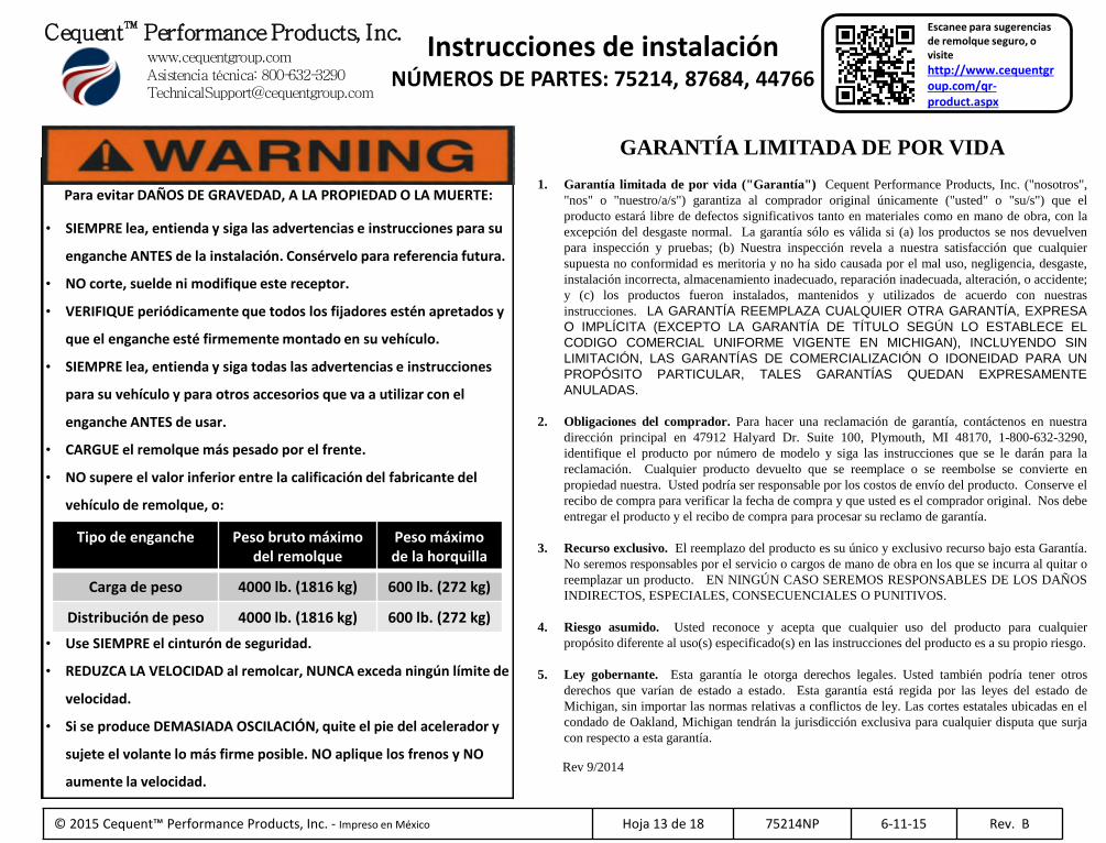
Para evitar DAÑOS DE GRAVEDAD, A LA PROPIEDAD O LA MUERTE:
• SIEMPRE lea, entienda y siga las advertencias e instrucciones para su
enganche ANTES de la instalación. Consérvelo para referencia futura.
• NO corte, suelde ni modifique este receptor.
• VERIFIQUE periódicamente que todos los fijadores estén apretados y
que el enganche esté firmemente montado en su vehículo.
• SIEMPRE lea, entienda y siga todas las advertencias e instrucciones
para su vehículo y para otros accesorios que va a utilizar con el
enganche ANTES de usar.
• CARGUE el remolque más pesado por el frente.
• NO supere el valor inferior entre la calificación del fabricante del
vehículo de remolque, o:
• Use SIEMPRE el cinturón de seguridad.
• REDUZCA LA VELOCIDAD al remolcar, NUNCA exceda ningún límite de
velocidad.
• Si se produce DEMASIADA OSCILACIÓN, quite el pie del acelerador y
sujete el volante lo más firme posible. NO aplique los frenos y NO
aumente la velocidad.
Tipo de enganche Peso bruto máximo del remolque
Peso máximo de la horquilla
Carga de peso 4000 lb. (1816 kg) 600 lb. (272 kg)
Distribución de peso 4000 lb. (1816 kg) 600 lb. (272 kg)
Escanee para sugerencias de remolque seguro, o visite
http://www.cequentgroup.com/qr-product.aspx
GARANTÍA LIMITADA DE POR VIDA
1. Garantía limitada de por vida ("Garantía") Cequent Performance Products, Inc. ("nosotros",
"nos" o "nuestro/a/s") garantiza al comprador original únicamente ("usted" o "su/s") que el
producto estará libre de defectos significativos tanto en materiales como en mano de obra, con la
excepción del desgaste normal. La garantía sólo es válida si (a) los productos se nos devuelven
para inspección y pruebas; (b) Nuestra inspección revela a nuestra satisfacción que cualquier
supuesta no conformidad es meritoria y no ha sido causada por el mal uso, negligencia, desgaste,
instalación incorrecta, almacenamiento inadecuado, reparación inadecuada, alteración, o accidente;
y (c) los productos fueron instalados, mantenidos y utilizados de acuerdo con nuestras
instrucciones. LA GARANTÍA REEMPLAZA CUALQUIER OTRA GARANTÍA, EXPRESA
O IMPLÍCITA (EXCEPTO LA GARANTÍA DE TÍTULO SEGÚN LO ESTABLECE EL
CODIGO COMERCIAL UNIFORME VIGENTE EN MICHIGAN), INCLUYENDO SIN
LIMITACIÓN, LAS GARANTÍAS DE COMERCIALIZACIÓN O IDONEIDAD PARA UN
PROPÓSITO PARTICULAR, TALES GARANTÍAS QUEDAN EXPRESAMENTE
ANULADAS.
2. Obligaciones del comprador. Para hacer una reclamación de garantía, contáctenos en nuestra
dirección principal en 47912 Halyard Dr. Suite 100, Plymouth, MI 48170, 1-800-632-3290,
identifique el producto por número de modelo y siga las instrucciones que se le darán para la
reclamación. Cualquier producto devuelto que se reemplace o se reembolse se convierte en
propiedad nuestra. Usted podría ser responsable por los costos de envío del producto. Conserve el
recibo de compra para verificar la fecha de compra y que usted es el comprador original. Nos debe
entregar el producto y el recibo de compra para procesar su reclamo de garantía.
3. Recurso exclusivo. El reemplazo del producto es su único y exclusivo recurso bajo esta Garantía.
No seremos responsables por el servicio o cargos de mano de obra en los que se incurra al quitar o
reemplazar un producto. EN NINGÚN CASO SEREMOS RESPONSABLES DE LOS DAÑOS
INDIRECTOS, ESPECIALES, CONSECUENCIALES O PUNITIVOS.
4. Riesgo asumido. Usted reconoce y acepta que cualquier uso del producto para cualquier
propósito diferente al uso(s) especificado(s) en las instrucciones del producto es a su propio riesgo.
5. Ley gobernante. Esta garantía le otorga derechos legales. Usted también podría tener otros
derechos que varían de estado a estado. Esta garantía está regida por las leyes del estado de
Michigan, sin importar las normas relativas a conflictos de ley. Las cortes estatales ubicadas en el
condado de Oakland, Michigan tendrán la jurisdicción exclusiva para cualquier disputa que surja
con respecto a esta garantía.
Rev 9/2014

Cequent™ Performance Products, Inc. www.cequentgroup.com Asistencia técnica: 800-632-3290 [email protected]
Instrucciones de instalación NÚMEROS DE PARTES: 75214, 87684, 44766
Aplicaciones:
Años Marca Modelos 2015-Actual* Ford Edge
*Visite nuestro sitio web para la información más actualizada respecto a los años de aplicación y los niveles de recorte.
Equipo necesario:
Trinquete Llave de torsión:
Gafas de seguridad
Tubos 5.5 mm 10 mm 3 / 4 ‘
NO SUPERE LA CALIFICACIÓN INFERIOR DEL
DEL FABRICANTE DEL VEHÍCULO DE REMOLQUE O:
Tipo de enganche Peso bruto máximo del remolque
Peso máximo de la horquilla
Carga de peso 4000 lb. (1816 kg) 600 lb. (272 kg)
Distribución de peso 4000 lb. (1816 kg) 600 lb. (272 kg)
Foto que representa al vehículo
© 2015 Cequent™ Performance Products, Inc. Impreso en México Hoja 14 de 18 75214NP 6-11-15 Rev. B
Tiempo de instalación: 30 min. El tiempo indicado anteriormente es el tiempo promedio para instaladores profesionales. Si usted no se siente cómodo para realizar esta instalación por su cuenta o necesita asistencia, sírvase ponerse en contacto con un instalador profesional.
Calificación de accesorios
Visite www.hitchmatch.net para más información
respecto a la equivalencia de enganches
Ilustración del enganche
Frente del
vehículo
Navaja utilitaria
Destornillador cabeza plana Lubricante o
agua jabonosa Marcador Cinta de
medir Lima

©2015 Cequent™ Performance Products, Inc. - Impreso en México Hoja 15 de 18 75214NP 6-11-15 Rev. B
1. Retire los paneles de apariencia en ambos lados cerca del receptáculo de la rueda y que cubren los largueros del bastidor, retire (2) tuercas hexagonales (cubo M10) en la parte inferior del larguero del bastidor y (2) tuercas hexagonales con un (cubo M5.5) en la parte inferior del larguero del bastidor. Ambos lados. Tendrá que recortar o eliminarlo una vez que el enganche esté en su lugar.
2. Baje el escape en los aisladores de goma en ambos lados del tubo de escape. Apoye el escape para evitar daños al vehículo. Nota: Rociar un lubricante o agua jabonosa en el vástago del colgante de metal y el aislante de goma ayuda para el desmonte.
3. Inserte el extremo enrollado del alambre de insertar a través del orificio trasero y saliendo por el orificio de acceso. Coloque el espaciador y el perno de carruaje en el alambre de insertar e inserte los fijadores en su ubicación a través del orificio. Deje el alambre de insertar unido. Repita el mismo proceso en ambos largueros del bastidor. Nota: Podría ser más fácil instalar la cabeza del perno de carruaje primero. Repita el procedimiento con los orificios delanteros. Ambos largueros del bastidor. Nota: para un ajuste apretado del perno de carruaje en el orificio de acceso podría ser necesario usar una lima o llave para abrir el orificio de acceso. Ver Figura 3.
4. Hale el alambre de insertar con los fijadores hacia su ubicación, a través del orificio. Deje el alambre de insertar unido. Repita el mismo proceso en ambos largueros del bastidor. Empuje los fijadores de nuevo hacia los rieles del bastidor con el alambre de insertar unido, para permitir que el enganche se acomode en su posición. Ver Figura 2.
5. Levante el enganche a su posición, pasando el alambre de insertar por los orificios en el enganche. Luego hale los fijadores de nuevo a través de los largueros del bastidor y los soportes del enganche. Repita el mismo proceso en ambos largueros del bastidor.
6. Inserte la arandela cónica sobre el alambre de insertar, usando la arandela para mantener el perno en su lugar, retire los alambres de insertar y coloque la tuerca hexagonal. Apriete para sostener el enganche en su lugar, repita para todos los fijadores.
7. El enganche tenderá a inclinarse en un ligero ángulo hacia abajo, empuje el enganche recto hacia arriba dentro del bastidor y apriete el enganche. 8. Apriete todos los tornillos 1/2-13 GR 5 con una llave de torsión a 75 Lb.-pies. (102 N*M) 9. Levante el escape de nuevo a su posición, rociando lubricante o agua jabonosa en el vástago del colgante de metal. Solo trabaje en un lado a la vez. Nota: todo el aislante de goma se puede mover en el vástago de metal para
volver a instalar el tubo de escape, será necesario empujar el aislante de goma hacia afuera, mientras se coloca el vástago de metal que queda de nuevo en su posición. 10. Recorte el panel de apariencia que se retiró en el paso 1 o devuélvalo al propietario. Obtenga el permiso del propietario antes de recortar. Con el área a recortar marcada, use una navaja utilitaria para recortar el área. Ver
Figura 4. Vuelva a instalar el panel apariencia
Nota: Revise el enganche con frecuencia, verificando que todos los tornillos y la esfera estén correctamente apretados. Si se quita el enganche tape todos los orificios en el colector del baúl u otros paneles de la carrocería para evitar la entrada del agua y los gases del escape. Se debe retirar y reemplazar un enganche o esfera que se hayan dañado. Observe las precauciones de seguridad al trabajar por debajo del vehículo y use protección visual. No corte los orificios de acceso o accesorios con soplete.
Este producto cumple con las especificaciones y requisitos de seguridad para conectar dispositivos y sistemas de remolque del estado de Nueva York, V.E.S.C. Regulación V-5 y SAE J684.
Figura 2
① Cant. (4) Perno de carruaje ½-13 x 1.75 GR5
② Cant. (4)
Espaciador .250 x 1 x 3
③ Cant. (4)
Arandela cónica ½”
④ Cant. (4)
Tuerca hexagonal ½ -13 GR2
⑤ Cant. (4)
Alambre de insertar ½-13
Atrás
Escanee para instrucciones de la
instalación paso por paso con FOTO, o visite http://www.cequentgr
oup.com/qr-product.aspx
Kit de fijadores: 75214 F
2’’
3’’
Figura 1
Instrucciones de instalación NÚMEROS DE PARTE: 75214, 87684, 44766
Se necesita la torsión adecuada para mantener el enganche unido firmemente al vehículo durante el remolque.
Siempre use GAFAS DE SEGURIDAD al instalar el enganche
①
②
③ ④
⑤
Costado con dientes
contra el enganche
Largueros del bastidor
Enrolle el alambre de insertar para mantener el espaciador
independiente del perno
Ejemplo del procedimiento del alambre de insertar
Orificio de acceso
Lima
Llave
Figura 3
Nota: Fijadores iguales
ambos lados
2” [50.8]
6” [152.4]
Orificio de acceso alargado
Figura 4
Recorte del panel

©2015 Cequent™ Performance Products, Inc. - Impreso en México Sheet 16 of 18 75214NP 6-11-15 Rev. B
1. Retire los paneles de apariencia en ambos lados cerca del receptáculo de la rueda y que cubren los largueros del bastidor, retire (2) tuercas hexagonales (cubo M10) en la parte inferior del larguero del bastidor y (2) tuercas hexagonales con un (cubo M5.5) en la parte inferior del larguero del bastidor. Ambos lados. Tendrá que recortar o eliminarlo una vez que el enganche esté en su lugar.
2. Baje el escape en los aisladores de goma en ambos lados del tubo de escape. Apoye el escape para evitar daños al vehículo. Nota: Rociar un lubricante o agua jabonosa en el vástago del colgante de metal y el aislante de goma ayuda para el desmonte.
3. Inserte el extremo enrollado del alambre de insertar a través del orificio trasero y saliendo por el orificio de acceso. Coloque el espaciador y el perno de carruaje en el alambre de insertar e inserte los fijadores en su ubicación a través del orificio. Deje el alambre de insertar unido. Repita el mismo proceso en ambos largueros del bastidor. Nota: Podría ser más fácil instalar la cabeza del perno de carruaje primero. Repita el procedimiento con los orificios delanteros. Ambos largueros del bastidor. Nota: para un ajuste apretado del perno de carruaje en el orificio de acceso podría ser necesario usar una lima o llave para abrir el orificio de acceso. Ver Figura 3.
4. Hale el alambre de insertar con los fijadores hacia su ubicación, a través del orificio. Deje el alambre de insertar unido. Repita el mismo proceso en ambos largueros del bastidor. Empuje los fijadores de nuevo hacia los rieles del bastidor con el alambre de insertar unido, para permitir que el enganche se acomode en su posición. Ver Figura 2.
Orificio de acceso

©2015 Cequent™ Performance Products, Inc. - Impreso en México Sheet 17 of 18 75214NP 6-11-15 Rev. B
5. Levante el enganche a su posición, pasando el alambre de insertar por los orificios en el enganche. Luego hale los fijadores de nuevo a través de los largueros del bastidor y los soportes del enganche. Repita el mismo proceso en ambos largueros del bastidor.
6. Inserte la arandela cónica sobre el alambre de insertar, usando la arandela para mantener el perno en su lugar, retire los alambres de insertar y coloque la tuerca hexagonal. Apriete para sostener el enganche en su lugar, repita para todos los fijadores.
7. El enganche tenderá a inclinarse en un ligero ángulo hacia abajo, empuje el enganche recto hacia arriba dentro del bastidor y apriete el enganche.
8. Apriete todos los tornillos 1/2-13 GR 5 con una llave de torsión a 75 Lb.-pies. (102 N*M)
Se necesita la torsión adecuada para mantener el enganche unido firmemente al vehículo durante el remolque.

©2015 Cequent™ Performance Products, Inc. - Impreso en México Sheet 18 of 18 75214NP 6-11-15 Rev. B
9. Levante el escape de nuevo a su posición, rociando lubricante o agua jabonosa en el vástago del colgante de metal. Solo trabaje en un lado a la vez. Nota: todo el aislante de goma se puede mover en el vástago de metal para volver a instalar el tubo de escape, será necesario empujar el aislante de goma hacia afuera, mientras se coloca el vástago de metal que queda de nuevo en su posición.
10. Recorte el panel de apariencia que se retiró en el paso 1 o devuélvalo al propietario. Obtenga el permiso del propietario antes de recortar.
Vuelva a instalar el panel apariencia
2” [50.8]
6” [152.4]
Panel trim
Destornillador cabeza plana
Con el área a recortar marcada, use una navaja utilitaria para recortar el área. Ver Figura 4.