Embed Size (px)
Citation preview

Drag Reduction for Viscous Laminar Flow on Spray-Coated Non-Wetting Surfaces†
Siddarth Srinivasan,a Wonjae Choi,b, Kyoo-Chul Park,c Shreerang S. Chhatre,a Robert E. Cohen∗a
and Gareth H. McKinley ∗c
Received Xth XXXXXXXXXX 20XX, Accepted Xth XXXXXXXXX 20XX
First published on the web Xth XXXXXXXXXX 200X
DOI: 10.1039/b000000x
We estimate the effective Navier-slip length for flow over a spray-fabricated liquid-repellent surface which supportsa compositesolid-air-liquid interface or ’Cassie-Baxter’ state. Themorphology of the coated substrate consists of randomly distributedcorpuscular micro-structures which encapsulate a film of trapped air (or ’plastron’) upon contact with liquid. The reductionin viscous skin friction due to the plastron is evaluated using torque measurements in a parallel plate rheometer resulting ina measured slip length ofbslip ≈ 39 µm, comparable to the mean periodicity of the microstructureevaluated from confocalfluorescence microscopy. The introduction of a large primary length-scale using dual-textured spray-coated meshes increases themagnitude of the effective slip length to values in the range94µm≤ bslip ≤ 213µm depending on the geometric features of themesh. The wetted solid fractions on each mesh are calculatedfrom simulations on model sinusoidal mesh geometries and thetrend in measured values ofbslip with the mesh periodicityL and the computed wetted solid-fractionrφs are observed to followexisting analytic predictions.
1 Introduction
The local shearing flow of Newtonian fluids close to a solidsurface is described by the Navier-Stokes equation along withan appropriate boundary condition on the velocity field at theliquid/solid interface. In macroscopic flows past smooth sur-faces, where the length scale of the system is much larger thanthe molecular length scale, the adoption of the no-slip bound-ary condition is widely accepted as valid.1 A more generalcondition used in various experimental studies investigatingslip at molecular length scales is the Navier-slip hypothesis,Vw = βτw , whereVw is the effective tangential surface ve-locity at the wall andτw is the local tangential shear-stress atthe interface. For a Newtonian fluid whose viscosity isη, thisexpression can also be written in the formVw = bslipγw, whereγw = (dV/dz)w is the local shear rate in the vicinity of thewall, andbslip = βη is the local slip length, a material propertyof the surface.1–3 Physically, the slip length corresponds to thedistance below the surface at which a linear extrapolation of
a Department of Chemical Engineering, Massachusetts Institute of Technol-ogy, Cambridge, MA, USA.b Department of Mechanical Engineering, University of Texasat Dallas, USA.c Department of Mechanical Engineering, Massachusetts Institute of Tech-nology, Cambridge, MA, USA.∗a E-mail: [email protected]∗c E-mail: [email protected]† Electronic Supplementary Information (ESI) available: [details of anysupplementary information available should be included here]. See DOI:10.1039/b000000x/
the velocity profile would satisfy the no-slip boundary con-dition.4,5 Multiple studies have investigated liquid-slip phe-nomena on smooth surfaces coated with low surface energymaterials for which the molecular interactions at the solid-liquid interface become weak.6–10 Although these investiga-tions demonstrate that the no-slip boundary condition is notstrictly valid, the resulting slip lengths across the solid-liquidinterface are generally too small (bslip ≈ 1 − 10 nm) to affectthe macroscopic liquid flow significantly.
A growing body of work has attempted to utilize ’super-hydrophobic’ textured surfaces with regular microfabricatedpatterns or hierarchical textures11–21 to amplify the effectivefluid slip at the interface. In such non-wetting surfaces, theliquid layer sits on a composite solid-air interface (or Cassie-Baxter interface22), by entrapping pockets of air between theindividual topographical features. The composite interfacecan robustly resist pressure-induced wetting transitionsover arange of liquid surface tensions and externally imposed pres-sure differences by careful design of the fabricated surfacemorphology.23,24 In facilitating the establishment of an airlayer or ’plastron’ that is stable to externally imposed pres-sure differences, such surfaces can reduce the frictional dissi-pation associated with laminar flows in microdevices,17,25 inrheometers,,20,26–28in pipes,21,29over coated spheres30 and inturbulent flows in channels.31 The reduction in viscous skinfriction due to the composite micro-textured interface canbesignificant in confined flows; in a seminal study Watanabe etal demonstrated a 14% reduction of drag in a 16 mm diame-
1–14 | 1

ter pipeline textured with a superhydrophobic surface.21 Thevast majority of subsequent investigations on superhydropho-bic surfaces have involved precisely-fabricated and regularly-patterned geometries which help develop a systematic under-standing of the influence of the wetted solid-fraction and sur-face periodicity in promoting large effective slip lengthsandassociated friction reduction. It is less clear whether sub-strates with randomly deposited micro-structures, which arecost-effective to manufacture and more readily applicabletolarge coated areas, would exhibit similar dramatic reductionin drag.5,32 Sbragaglia & Prosperetti33 and Feuillebois et. al34
propose theoretical models to investigate how random texturescan enhance the effective slip at a fluid-solid interface. Inthepresent work, we use parallel-plate rheometery to determinethe effective slip length for flow over spray-fabricated corpus-cular microtextures that are randomly deposited over both flatsubstrates and on woven wire meshes.
In Figure 1, we illustrate conceptually the effective slippresent at the interface for flow over a spherically texturednon-wetting substrate in the presence of an unconfined or pres-sure driven flow (Figure 1a) and also in a laminar Couette flow(Figure 1b). In each of these cases, the conventional no-slipcondition is valid on the top of the wetted textures, while thelocal fluid velocity at the liquid-air interface is determined bya tangential stress-balance. The net dissipative interaction ofthe fluid with this textured surface can be expressed using anarea-averaged effective slip velocity〈Vw〉, or alternatively interms of an effective slip length〈bslip〉, again averaged overthe periodicity (L) of the textured surface. As indicated inFigure 1, the slip length〈bslip〉 can be greater than the charac-teristic scale of the texture (2R); a larger value of slip lengthindicates higher friction-reducing ability of the correspondingtextured surface. For the laminar Couette flow shown in Fig-ure 1b, the shear rateγ in the fluid and the resulting shearstressτ vary linearly except in the immediate vicinity of thesurface texture. The apparent shear rate in the Couette flowwith the assumption of a no-slip boundaryγa = Vplate/h canbe related to the true shear rateγt that is established in thefluid in the presence of slip asγah = γt(h + 〈bslip〉), whereh is the gap height.35 For a Newtonian liquid with viscosityηand shear stressτ = ηγ, measurement of the frictional forcesor torques (in a torsional rheometer) due to flow at a fixedheight between two flat parallel rigid surfaces (with no slip)and textured non-wetting surfaces (with slip) enables the ef-fective slip length on the latter to be directly related to themeasured viscous friction using a rheometer.20,26,27The vis-cous stress for a linear Couette flow in the proximity of thetop plate can be expressed asτslip = ηVplate(h + 〈bslip〉)−1 =ηγa(1 + 〈bslip〉/h)−1, whereVplate is the velocity of the upperplate. In a parallel-plate rheometer with disc radiusR, the to-tal torqueM =
∫
2πr2τdr measured by the instrument fora Newtonian fluid is36 M = (πηγaR
3)/2. Therefore, for a
Fig. 1 (a) A schematic diagram showing a liquid flow on a texturednon-wetting surface, possessing an effective velocityVw that isaveraged over the texture periodL. (b) A laminar Couette flow withaverage shear rateγa = Vplate/h between a non-wetting texturedbottom surface exhibiting an average slip length〈bslip〉 and aconventional flat solid top surface possessing a no-slip boundarycondition.
fixed upper plate velocity, the ratio of the apparent viscosities(or measured torques) between (i) two flat surfaces with noslip and, (ii) a flat surface and a textured non-wetting surfacewith slip can be directly related to the average slip as,
ηflat
ηslip=
τflat
τslip=
Mflat
Mslip= 1 +
〈bslip〉h
(1)
Eqn. 1 implies that in order for fluid slip in confined laminarflows to be manifested as a significant effect, the magnitude ofthe slip length〈bslip〉 should be comparable to the length scaleof the flowh (i.e.,b/h ∼ O(1)). This can be readily achievedin a a rheometer because gaps in the rangeh . O(100µm)can be attained reliably.50 A more universal measure of fluidslip is the amount of drag reduction (DR) associated with thereduction in the measured apparent viscosities and can thusbewritten for a torsional Couette flow as:
DR = 1− ηslip
ηflat=
bslip
h+ bslip(2)
Rheometric torque measurements can therefore be usefullyemployed as a macroscopic measurement technique that pro-vides a systematic method to probe area-averaged microscopicliquid-slip phenomenon over a large random (and possiblyanisotropic) surface morphology. Care must however be takento ensure that edge effects are eliminated and systematic errorsare minimized.26,37,38
1.1 Relationship between slip length and surface texturalparameters
The dependence of the effective slip length on the topographicproperties of non-wetting textured surfaces has been analyti-cally modeled using two limiting scenarios; (i) flow over a
2 | 1–14

plastron of finite thickness, and (ii) flow over surfaces withalternating regions of slip and no-slip. In the former case,for a liquid slipping over a homogeneous layer of air withthicknessδ, the slip length is expressed as a product of theratio of the viscositiesηliquid/ηair and a function of the plas-tron thickness.19,30 McHale et al30 show that up to 30% dragreduction can be achieved for plastron-supporting spheresatthe optimal plastron thickness. In the latter case, typicalval-ues of slip length on micro-textured non-wetting surfaces areon the order of tens of micrometers13,28,39and are dependenton the morphological patterning of the surface texture.12,17
The topographical features needed to entrap microscopic airpockets at the textured surface also act as regions where theconventional no-slip boundary condition still applies foreachof the solid-liquid interfaces formed on the texture elements(blue solid lines in Figure 1b). Therefore, the average valueof the effective slip length becomes strongly dependent bothon the fraction of the wetted solid-liquid interface (denotedrφs) and regions of slip and no-slip,4,40 as well as the specificgeometric arrangement of these regions.41,42 For discrete tex-tures such as periodically arrayed pillars or beads, a genericscaling law was developed by Ybert et al43 that predicts thatthe slip length scales as〈bslip〉∼a/(rφs) in the limit rφs → 0,whererφs is the wetted area fraction anda is the length scalecorresponding to the size of individual surface features. Thescaling law can be expressed in terms of the periodicity of thesurface textureL as 〈bslip〉 ∼ L log(1/(rφs)) for 1D stripesandbslip ∼ L/
√rφs for 2D posts.44 The validity of this model
was demonstrated by numerical simulations and later by ex-periments with microfabricated surfaces.14 The scaling lawis also consistent with a number of studies that obtain an-alytical solutions of slip lengths for flow over 1D groovedand striped geometries.4,44,45 Recent work by Ng & Wang46
and Lauga & Davis47 in solving for slip flow over micro-structures comprising periodic 2D circular posts obtains an in-verse square root dependence of the slip length with the solidfraction〈bslip〉 ∼ L/
√rφs. In the present work, we use fluo-
rescence microscopy and contact-angle measurements to ob-tain estimates of the mean periodicity〈L〉 and the wetted areafraction rφs of a random microtexture in order to comparepredictions from these theoretical models to the slip lengthsobtained experimentally from rheometry.
2 Materials and Methods
2.1 Single Step Fabrication of Large Area Spray-CoatedNon-Wetting Surfaces
A mixture of 50/50 wt% poly(methyl methacrylate) (Sig-maAldrich; Mw=102,000 g/mol; PDI=1.56) and thehydrophobic molecule 1H,1H,2H,2H-heptadecafluorodecylpolyhedral oligomeric silsesquioxane (fluorodecyl POSS),
whose method of synthesis has previously been reported,48
was dissolved in the commercially available solvent Asahik-lin AK-225 at a concentration of 50 mg/ml. The mixture wassubsequently spray-coated49 onto circular silicon disks usingan airbrush connected to a pressurized nitrogen stream at adistance of 20 cm and an operating pressure of 170 kPa. InFigure 2a, we show a scanning electron micrograph of themicro-structure produced by jet break-up of the polymer so-lution during the spraying process. As seen from Figure 2a,the surface structure consists of randomly-deposited corpus-cular beads of characteristic diameter∼ 20µm. The non-volatile PMMA acts as a sticky binder that adheres to the sil-icon surface. The presence of the hydrophobic fluorodecylPOSS molecules along with the re-entrant micro-structuredmorphology confers the textured and fluorine rich surfacewith super non-wetting behaviour, which we have character-ized in previous work.49 In the inset of Figure 2a, we showa drop of water of volume∼ 5µl deposited on the spray-coated substrate. The drop exhibits an apparent advancingcontact angle ofθ∗ = 161◦ and no observable hysteresis.A water immersion test was performed to test the robustnessagainst a pressure-induced wetting transition to the Wenzelstate, and the spray-coated substrate remained in the com-posite or Cassie-Baxter state, as evidenced by the continuedpresence of the plastron, through the entire height of the watercolumn (45 cm), which corresponds to a maximum pressure of4410 Pa. A number of woven metal meshes with various to-pography and characteristic length scales were also purchasedfrom McMaster-Carr and conformally spray-coated with the50 wt% PMMA/fluorodecyl POSS solution to produce hierar-chical or dual length scale textures.
2.2 Rheometeric Quantification of Drag Reduction andthe Slip Length
An AR-G2 rheometer (TA instruments, New Castle, DE19720) with a standard plate-plate geometry as shown in Fig-ure 2b was utilized to impose a shear rate and measure theresulting viscous torque on the samples. Equation 1 is thenused to calcuate the resulting average slip lengths. A trans-parent upper acrylic plate of 60 mm diameter was used forall measurements. The spray-coated silicon substrates wereaffixed firmly to the lower Peltier plate using double-sided ad-hesive tape, and the upper plate was lowered to set the zero-gap height and ensure parallelism. Conventional rotationalrheometers become prone to error in zeroing the gap whenvery narrow fluid gaps are employed.50 The error in gap heightduring calibration due to the plate-plate configuration waspre-viously determined as35 µm, although the non-flatness of thetextured spray-coated substrate and the squeeze flow of air cancontribute to an additional error.51,52 To minimize contribu-tions from these errors, a series of measurements were made
1–14 | 3

Rotating Plate
(Top)
Superhydrophobic
Substrate (Bottom)
Liquid
Fig. 2 (a) SEM image of spray-coated superhydrophobic surfacedisplaying corpuscular micro-structured morphology (b) Schematicof plate-plate fixture mounted on a controlled stress rheometer usedto quantify apparent slip lengths using a 50 vol% glycerol/watermixture as probe liquid
at various gaps, from h = 500µm to 2500µm. After the zero-gap calibration is complete, rotational mapping was carriedout to account for residual system torques in the rheometer.Tests were performed at shear rates ranging between10− 100s−1, unless specified otherwise.
2.3 Parameters influencing the rheometric measurementof effective slip length
There has been some discussion in the literature about theexperimental reliability of obtaining accurate measurementsof slip lengths via rheometry37 as there are potential sourcesof systematic experimental error in the resolution of torquemeasurements, determining the gap height, presence of sec-ondary flows and meniscus effects which need to be care-fully accounted for.38 As shown in ESI (Figure S1)†, a ref-erence Newtonian oil (n-decane; 25◦C; η = 0.8538 mPa.s)was used for instrument calibration to obtain measurementsof torques which yielded an experimental apparent viscosityof 0.85 ± 0.01 mPa.s for flow over a flat-surface. The appar-ent viscosity was observed to be uniform over shear rates fromγ = 10− 100 s−1 as expected with the corresponding torquesranging between0.3− 1.3 µN.m. While the torque resolutionof the ARG2 rheometer in steady shear is 10 nN.m,53 scat-ter due to noise in the torque measurements was observed tobe δM ≈ 0.2 µN.m. To amplify the magnitude of torquevalues, we use a 50 vol % glycerol/water as the Newtonian
probe liquid with a measured viscosity of6.2 ± 0.05 mPa.sat 25◦. The values of measured torques ranged from3 − 30µN.m for shear rates betweenγ = 10 − 100 s−1 (as shownin ESI Figure S1†). The choice of a 50 vol% glycerol/wateras the probe liquid ensures that the range of measured torquesM is much larger than the practical torque resolution limitof 0.2µN.m. The uncertainty in torque measurement is thus0.7% at a shear rate of 100 s−1. The effects of inertia and sec-ondary flow are negligible over the range of shear rates used.54
Bocquet et al37 draw attention to an important source of sys-tematic bias in measured torque in parallel-plate rheometry onsuperhydrophobic surfaces due to the curvature of the liquidmeniscus at the radial edge of the parallel plate, which canerroneously be interpreted as slip. The curvature of the freesurface of the liquid filling the gap between the plates dependson the local contact angle at the radial edges of the test fix-tures and gives rise to a mismatch in the wetted area. Thedecrease in the wetted radius is amplified on the spray-coatedsuper-hydrophobic substrate which exhibits an effective con-tact angle ofθ∗ ≃ 160◦. As described in ESI Figure S2†,we introduce a thin hydrophilic circular strip of thickness200µm at a radiusR in order to pin the liquid meniscus at theedge of the parallel plate. The reference torque measurementsare performed on flat rigid surfaces with an advancing contactangle ofθ∗ = 90◦ obtained by spin-coating a silcon waferwith a 5%/95% weight fraction fluorodecyl POSS/PMMA so-lution. This ensures that the area wetted by the liquid on thelower superhydrophobic surface is identical to that on the flatsurface, minimizing the error associated with the edge effect.Furthermore, instead of using a single torque measurment todetermine the effective slip length, a series of measurementswere performed at a number of different gap-heights, and theslip length was estimated from a least-squares fit of Eq. 1 toreduce the effect of zero-gap errors.
3 Results and Discussions
In Figure 3, we show the apparent viscosities of a 50 vol% glycerol/water solution measured at a fixed gap height ofh = 1000 µm on three different surfaces. For this New-tonian fluid, the viscosity is rate-independent and the meanvalue of the apparent viscosities are calculated as an averageover the entire range of shear rates tested. For a flat spin-coated silicon wafer, the averaged viscosity was measured asηflat = 6.2 ± 0.05 mPa.s, which corresponds to the situationwhen there is no fluid slip. The averaged apparent viscosityfor the spray-coated superhydrophobic corpuscular substrateshown in Fig. 2a isηslip = 6.0 ± 0.15 mPa.s correspondingto 3% reduction in the viscous drag and a spray-coated super-hydrophobic woven mesh has an averaged apparent viscosityof ηmesh
slip = 5.5 ± 0.14 mPa.s corresponding to a 11% reduc-tion in drag at a gap-height ofh = 1000µm. The lower val-
4 | 1–14

Fig. 3 Apparent viscosities of 50 vol% glycerol/water mixturemeasured for a gap separation ofh = 1000 µm on (i) flatspin-coated hydrophobic surface; (ii) Spray-coatedsuperhydrophobic silicon wafer; (iii) Spray-coatedsuperhydrophobic mesh with wire radiusR=254µm and meshspacingD=805µm.
ues of the apparent viscosities on the spray-coated substratesis indicative of a reduction in drag due to partial fluid slip atthe composite interface. However, as noted it is not prudentto use measurements at a single height for the rheometric es-timation of the slip length as uncertainties in zeroing the gapheight and meniscus edge effects can be misinterpreted as con-tributions to the total slip. To minimize potential artifacts inthe estimation of the effective slip length, measurements ofthe ratio of apparent viscosities on the flat substrate to that ofthe spray-coated substratey(i) = (ηflat/ηslip)
(i) (averaged overshear rates as per Fig. 3) were repeated at various gap sepa-rationsh(i). Linear regression of Eqn. 1 to values ofy(i) fordifferent values ofx(i) = 1/h(i) was then used to determinethe best fit slope, which then yields the averaged effective sliplength〈bslip〉.
3.1 Single-textured Surfaces
In Figure 4, we plot the ratio of(ηflat/ηslip)(i) against the in-
verse gap height1/h(i) for the spray-coated silicon substratefor gap heights fromh(i) =500µm toh(i) =2000µm in incre-ments of 250µm averaged over shear rates between10− 100s−1. There are potentially a number of local wetting con-figurations of the composite interface upon each loading ofthe liquid in the parallel plate geometry, giving rise to varia-tions in the measured apparent viscosity. The error bars corre-spond to experimental standard deviations over four sets ofmeasurements at each gap height for the flat and sprayed-coated surfaces. Each data point at a particular gap heightwhereηflat/ηslip > 1 indicates the manifestation of effective
h
Fig. 4 Ratio of shear viscosity measured in contact wioth a flatsurface to the apparent viscosity measured on the spray-coatedsuperhydrophobic surface plotted against the inverse gap height.The effective slip length is extracted from a linear regression usingEq. 1, and the corresponding 95% confidence bands are plottedasdashed lines.
slip, and a corresponding reduction in drag. A single parame-ter constrained best fit to the linear model in Eqn. 1 was per-formed and an instrumental weighting was used for the stan-dard deviations (i.e., the weighting functionwi = 1/σ2
i), so
that data points with larger deviations are assigned less im-portance. The mean value of the effective slip length for thespray-coated silicon substrate isbslip ≈ 39 µm with a 95%upper confidence limit of51 µm and a 95% lower confidencelimit of 28 µm. The corresponding confidence bands are plot-ted as dashed lines in Figure 4. The extent of drag reductionobserved is a function of the spacing between the plates asseen in Eqn. 2, and varies from 7 % for a gap-height of 500µm to 2 % for a height of 2000µm (2 mm).
The effective slip on randomly deposited textures is de-scribed by a tensorial quantity that varies depending on thelocal flow and the geometry specific to that region.41 There-fore, the numerical value of〈bslip〉 ≈ 39 µm we obtain fromrheometry is a macroscopic averaged representation of themore complex velocity profiles that are established close tothe rough hydrophobic texture shown in Fig. 2a. In order tounderstand the relationship between the mean spacing〈L〉 ofthe beaded microstructures (Fig. 2a) and the values of〈bslip〉obtained from torque measurements on our sprayed surface,we consider an equivalent periodic model geometry with thesame wetted solid-fraction as the sprayed substrate. It is con-venient to use the Cassie-Baxter equation written in the form,cos θ∗ = rφs cos θE − 1 + φs, to determine the wetted areafraction rφs. Using a model of hexagonally packed spheresfor the corpuscular structures, we have previously estimated49
the total wetted fraction asrφs ≈ 0.1, whereθ∗ = 160◦ is the
1–14 | 5

macroscopic apparent contact angle on the sprayed substrateandθE = 124◦ is the equilibrium contact angle on a flat spin-coated substrate with the same chemical composition as themixture that is sprayed onto the substrate.
In order to use hydrodynamic models to evaluate the pre-dicted slip present on a composite textured surface in whichthe wetted fraction is onlyrφs ≃ 10% it is necessary to de-termine the characteristic length scale (denoted〈L〉) of therandom sprayed texture. We calculate the mean periodicitybetween the individual corpuscular features in Figure 2b byincorporating fluorescent red dye (Nile red) in the fluorode-cyl POSS/PMMA solution. The sample was then illuminatedwith a Helium/Neon (He/Ne) 543nm laser, and the fluores-cence was imaged using a Zeiss LSM 510 confocal micro-scope. The presence of the red dye, which is embedded inthe microstructures produced on spraying, allows for mappingof the three-dimensional surface morphology (for details seeESI Figure S3†). In Figure 5, we show a142 µm x 142 µmplanar cross-section of the spray-coated corpuscular substrateimaged at a depth of 25µm, which corresponds to the verti-cal midplane of the sprayed surface morphology. The con-focal image was thresholded and converted to a binary im-age using the freely-available ImageJ software package.55 Thelight regions in Figure 5 correspond to the voids inbetween thecorpuscular microstructure, and the dark region indicatesdo-mains of fluorodecyl POSS/PMMA. The location of the cen-troids of each of these domains was determined by particleanalysis, and the mean periodicity was obtained from the cen-troids using the Delauney triangulation technique as〈L〉 ≈ 32µm. The calculation of〈L〉 andrφs for the spray-coated cor-puscular morphology allows us to compare our experimentallymeasured slip length with analytical predictions that havebeenobtained for model periodic geometries. Ybert et al43 demon-strate that for a 2D array of solid patches in a square lattice,the slip length scales as:
bslip
L=
A√rφs
−B (3)
whereA andB are numerical constants that depend on thegeometry of the patches. For periodic circular patches, thevalues ofA,B are found by Ng & Wang46 to beA ≈ 0.34& B ≈ 0.468 using numerical regression, and by Lauga &Davis47 asA = 3
√π/16 ≈ 0.332 & B = 3 ln(1+
√2)/2π ≈
0.431 using analytical methods. Substitution ofrφs ≈ 0.1and〈L〉 ≈ 32 µm yields a predicted value of the slip lengthbpred≈ 19 µm that is within a factor of two of our experimen-tal result of〈bslip〉 ≈ 39 µm. The simple analytical modelof an array of 2D circular patches is thus able to qualita-tively predict the effective slip phenomenon measured nearthespray-coated corpuscular micro-structures as a function of themean periodicity〈L〉 and the wetted fractionrφs. Althoughthe mean periodicity between the features of the corpuscular
20 µm
Fig. 5 Confocal Microscope slice image of the spray-coatedsurface tagged with a Red Nile dye and imaged at the mid-plane.The overlaid lines correspond to the Delaunay triangulation of thecentroids of the individual microtextured features (determined fromthe ImageJ software), and is used to determine the mean periodicityL
microstructure is limited by the operating parameters of thespray-coating system, we show in the next section that we canfurther enhance the effective slip by introduction of an addi-tional length-scale via dual-textured mesh substrates.15,56
3.2 Dual Textured Surface
Commercially woven wire meshes are readily available witha range of characteristic length scales and pore sizes at com-paratively low costs. While most rigid metal meshes are hy-drophilic, non-wetting hydrophobic meshes have been shownto support composite air-liquid interfaces56,57 and are goodcandidate surfaces for reducing fluid drag. We use thespray-coating technique described earlier to deposit fluorode-cyl POSS/PMMA microstructures onto various woven wiremeshes, whose dimensions are summarized in Table 1. InFigures 6a and 6b, we show scanning electron micrographsof a stainless steel mesh (Mesh II;R = 127 µm, D = 330µm) that has been conformally spray-coated with the corpus-cular microstructures. The spray-coated meshes exhibit su-perhydrophobic non-wetting behaviour and support a hierar-chical composite air-liquid interface on two distinct scales: (i)on large scales of characteristic width2D between the indi-vidual woven wires (of diameter2R) that comprise the meshas shown in Fig. 6a and (ii) on smaller regions consisting oftrapped air between the spray-coated corpuscular regions onthe surface of the individual wires (shown in Fig. 6b) witha mean periodicity〈Ls〉 ≈ 32µm as discussed in the earliersection.
The reduction in the total wetted area fraction on this hi-
6 | 1–14
erarchical structure is expected to further reduce the viscousfriction. However, a number of sources including the menis-cus curvature, gravity, inertia, and other body forces can giverise to a pressure difference that drives the liquid-air interfaceinto the air pockets entrapped within the mesh.23,58 The mainsource of external pressure in the plate-plate rheometer systemis the Laplace pressure from the curvature of the meniscus asit sits on the wires. This Laplace pressure is inversely relatedto the gap separationh as:
∆P = −2γlv cos θ/h (4)
whereθ = 160◦ is the apparent contact angle on the micro-textured coating that has been applied on the wires of themesh andγlv is the liquid surface tension. The magnitudeof the applied pressure difference∆P for the 50 vol% glyc-erol/water liquid varies from 64 Pa to 128 Pa for gap sep-arations between 1000µm and 2000µm. The maximumpressure difference that can be supported across a liquid/aircomposite interface scales asPb ∼ γlv/Rc, wherePb is thebreakthrough or impalement pressure andRc is a character-istic length of the geometry.59–61 For the dual-textured mesh,this characteristic length will scale with the mesh periodic-ity (Rc ∼ L = 2R + 2D) for the larger air pockets trappedbetween the wires, and with the mean periodicity of the cor-puscular microstructures (Rc ∼ 〈L〉) for the smaller regionon each wire. The large length scale of the mesh adverselyaffects its ability to maintain the pockets of air inbetweenthemesh wires against a pressure perturbation across the air film.For the cylindrically textured mesh surfaces used in this work,an approximate analytical expression for the breakthroughorimpalement pressure was previously determined as:24
Pb =2γlvL
(
2D∗
D∗ − 1
)[
(1− cos θ)
(D∗ − 1 + 2 sin θ)
]
(5)
The breakthrough pressurePb is thus a function of the ap-parent contact angleθ and a dimensionless geometrical spac-ing ratioD∗ = (R+D)/R. Therefore, as long as the externalpressure∆P < Pb, the composite liquid/air interface is stillstable and when∆P ≃ Pb, a wetting transition occurs in thelarge pockets of air trapped inbetween the wires. The coatedsurface of the individual wires are themselves strongly non-wetting (i.e. θ = 160◦) and continue to maintain their non-wetting characteristic (even after breakthrough in the large airpockets) due to the smaller length scale of the microtexturesformed by the spraying process.
In Figure 6c, we show an image of the composite interfacethat is established upon depositing the glycerol/water probeliquid between the spray-coated mesh and a transparent upperplate. The image is obtained using a CCD camera focusedthrough the upper plate at an oblique angle (for schematic, seeESI Figure S4†). The dark region in Fig. 6c corresponds to
the solid/liquid/air interface resting on the corpuscularstruc-tures that have been sprayed on the wires of the woven mesh,while the light region corresponds to incident light reflectingoff the large pockets corresponding to the liquid/air interface.The position of the liquid/air interface depends on the externalpressure∆P . A comparison between the composite interfacethat develops on the meshes in the plate-plate rheometer andthe simulated interface at a pressure differential of∆P = 100Pa is provided in Figs. 6c and 6d. The meniscus configu-ration is calculated using the public domain Surface Evolverpackage.62 The simulation captures the essential details of thecomposite interface system, including the wetted solid frac-tion rφs and the air-liquid fractionφa.
Such calculations can be combined with experimental mea-surements at different gap separations (and thus, from Eqn.4,corresponding to different applied pressures) to understand theprogressive decrease in the friction reduction that is achiev-able. Equation 5 serves as a framework to allow for a rationalselection of non-wetting meshes. The equation can be non-dimensionalized by a reference pressurePref = 2γlv/lcap toobtain a dimensionless scaled breakthrough pressureA∗ =Pb/Pref where lcap =
√
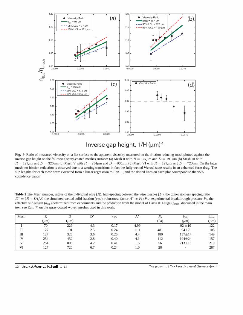
γlv/ρg is the capillary length ofthe liquid. The reference pressure corresponds to the capil-lary pressure for a large drop of sizelcap, and is a measureof the pressure differential across a millimetric scale liquiddroplet. Therefore,A∗ . 1 is the appropriate criteria for thespontaneous wetting transition of the composite interfacefora liquid drop on a freely suspended mesh. Six meshes withvarying wire radiiR and mesh spacingD satisfyingA∗ & 1were spray-coated and the breakthrough pressurePb for eachsprayed mesh was experimentally determined by vertical im-mersion into a 50 vol% glycerol/water solution using a dy-namic tensiometer and analysis of the resultant force curves(see ESI Figure S5†). In order to prevent an irreversible wet-ting transition during the rheometry experiments, the underly-ing flat surface on which the mesh was horizontally affixedwas also spray-coated with the corpuscular microtexture tomake it superhydrophobic. The experimentally measured val-ues ofPb are shown in Table 1, along with the values ofD∗
andA∗. The measured breakthrough pressures are qualita-tively consistent with the simple cylindrical model. As higherpressures are applied across the composite liquid-air interface,the liquid meniscus descends into the weave of the mesh un-til the meniscus between the wires collapses and rests on thebottom surface. Therefore, the numerical value ofA∗ canalso be interpreted as a robustness factor, i.e., a measure ofthe susceptibility of the meniscus to exhibit this sagging be-haviour. Meshes withA∗ ≫ 1 are robustly metastable, whilemeshes exhibitingA∗ ≈ 1 are more prone to a wetting transi-tion.23,24,60The presence of the flat spray-coated bottom sub-strate and the connectivity of the air pockets allow the menis-cus to reversibly recover to its original location upon removal
1–14 | 7

127R mµ=
2D2R
330D mµ=
(a) (b)
(d)(c)
wetted solid
liquid
Fig. 6 (a,b) Scanning electron micrographs at different magnifications of the dual-textured spray-coated superhydrophobicmesh surfaces; (c)image of the solid-liquid-vapor composite interface for a 50 vol% glycerol/water solution resting between a spray-coated mesh and the upperrotating plate of the rheometer. The dark regions indicate the wetted area of the mesh and the light regions correspond toreflection of incidentlight off the liquid meniscus. The inset shows the structureof the spray-coated mesh in the dry state (d) The composite interface on a modelsinusoidal woven mesh, simulated using Surface Evolver FEMsoftware. The dark blue, light blue, and red colors represent the wetted solid,liquid-air meniscus and the dry mesh surfaces respectively. The inset depicts the structure of the periodic mesh in the dry state.
8 | 1–14

D*
Mesh Periodicity , L (μm)
VI
VI
II
III
IV
Fig. 7 The design chart for ideal flat non-wetting mesh surfaces,with contours of fixed slip length plotted as solid red lines (from Eq.6) and contours of fixed robustness factorA∗ drawn as dashed blacklines as a function of the dimensionless spacing ratioD∗ = (R +D)/R and the mesh periodicityL = 2D + 2R. Theshaded region indicates parts of the design space whereA∗ < 1 andthe liquid meniscus will penetrate into the mesh. The data pointscorrespond to the location in the design space of the varioussuperhydrophobic coated meshes used in this study.
of the pressure difference acting on the plastron.Davis & Lauga63 have analytically studied liquid flow along
the principal direction of an ideal flat 2D continuous mesh sub-strate, and obtain an asymptotic estimate for the slip lengthin the limit of a widely spaced mesh of thin rungs (D∗ =(R+D)/R ≫ 1) as
bideal ≈L
3πln
(
2D∗
π
)
(6)
where,L = 2R+2D is the mesh periodicity. Eqns. 5 and 6clearly convey the inverse correlation between the magnitudeof the slip length and the robustness of the composite inter-face. Any attempt to increase the slip length by increasingD∗
andL will directly result in a reduction in the robustness ofthe composite interface. In Figure 7, we illustrate this inversecorrelation by means of an engineering design chart consist-ing of fixed contours of the the robustness factorA∗ and theslip length on an ideal meshbideal (computed from Eqns. 5 and6 respectively) plotted as a function of the mesh periodicity Land the spacing ratioD∗, with the shaded portion indicatinginaccessible regions of the design space (whereA∗ < 1, cor-responding to a spontaneous wetting transition). Fig. 7 pro-vides a systematic framework with which to design the geom-etry of non-wetting meshes for reducing frictional drag, whileclearly illustrating the difficulty of simultaneously achievingboth large liquid slip lengths and high robustness. The variousmeshes used in this study are also indicated in Fig. 7 by points
I-VI, and experiments to calculate their friction reducingchar-acteristics are discussed in the following sections.
It is important to note that a number of assumptions inthe ideal model system considered by Davis & Lauga arenot strictly valid during parallel plate rheometry over thespray-coated mesh surfaces. These include the existence ofa continuously-connected solid/liquid wetted region, a flat liq-uid/air interface, and the uniform directionality of the imposedflow. Despite the continuous nature of the fibrous wovenmeshes shown in Fig. 6a, the real contact regions betweenthe liquid and the textured solid surface consists of arraysofdiscrete elliptical wetted patches as shown in Fig. 6d. In or-der to calculate the expected frictional drag of these mesh sur-faces it is necessary to evaluate the wetted surface fractionas it evolves with the imposed pressure. A set of simulationscomputing the deformation of the liquid-air interface on modelsinusoidal woven meshes under an imposed pressure differen-tial were performed using Surface Evolver. In Figures 8a and8b, we illustrate the computed shape of the composite liquid-air meniscus on Mesh II (with robustness factorA∗ = 11.1)at pressure differentials of∆P = 100 Pa and∆P = 500 Parespectively. The total wetted solid fraction calculated fromthe simulation increases fromrφs = 0.24 at∆P = 100 Pa torφs = 0.78 at∆P = 500 Pa. At a fixed pressure differentialof ∆P = 100 Pa, the wetted fractionrφs also depends on thegeometry of the woven mesh. The more open Mesh IV (Fig.8c) has a reduced robustness factor (A∗ = 4.1), and conse-quently the liquid interface penetrates deeper into the mesh,corresponding to a larger wetted solid fraction ofrφs = 0.40.In Figure 8d, we show the variation of the total liquid/solidwetted area fractionrφs and liquid/air area fractionφa withthe imposed pressure differential∆P . The woven topographyof the meshes allows for the sumrφs + φa > 1 in general.The liquid-air interface visibly distorts or ’sags’ with increas-ing pressure differences, considerably increasing the wettedsolid fractionrφs on the given texture and correspondinglyweakening the overall friction reduction that can be expected.In Table 1, we present the wetted solid fractions on each meshused in this study calculated at an intermediate pressure dif-ferential of∆P = 100 Pa.
On an ideal flat mesh,rφs is directly related to the dimen-sionless geometrical spacing ratio asD∗ ≡ (R + D)/R =(1 +
√1− rφs)/rφs. While it is clearly evident from the
surface evolver simulations that the model of an continuouslyconnected flat mesh is not strictly correct for robustly non-wetting meshes, the simulated values ofrφs can be used toobtain an alternative estimate for the slip lengthbmeshon a wo-ven texture from Eqn.7:
bmesh≈L
3πln
(
2(1 +√1− rφs)
πrφs
)
(7)
Equation 7 enables us to evaluate the expected value of the
1–14 | 9

R=127µm; D=191µm; ΔP=500 Pa
(b)
(d)(c)
R=254µm; D=452µm; ΔP=100 Pa
R=127µm; D=191µm; ΔP=100 Pa
(a)
=0.40
=0.24 =0.78
Fig. 8 The simulated composite interface and wetted solid fractions (rφs) on sinusoidal woven wire meshes of diameterR = 127µm andspacingD = 191µm (corresponding to Mesh II), calculated using Surface Evolver at imposed pressure differentials of (a)∆P = 100 Paresulting inrφs = 0.24 and (b)∆P = 500 Pa resulting inrφs = 0.40 (c) The simulated composite interface corresponding to Mesh IV(R = 254µm; D = 452µm) at∆P = 100 Pa withrφs = 0.40 (d) The variation of the wetted solid fractionrφs and the air-liquid areafractionφa with increasing pressure differential arising from the Laplace pressure associated with decreasing plate-plate height (∆P ∝ 1/H ,see Eqn. 4).
10 | 1–14

slip length that can be generated for the spray-coated wovenmeshes, where the value ofrφs is estimated for a mesh ofgiven geometrical dimensions using Surface Evolver as shownin Fig. 8. We present predictions of the effective slip lengthin Table 1 along with values obtained experimentally fromrheometry.
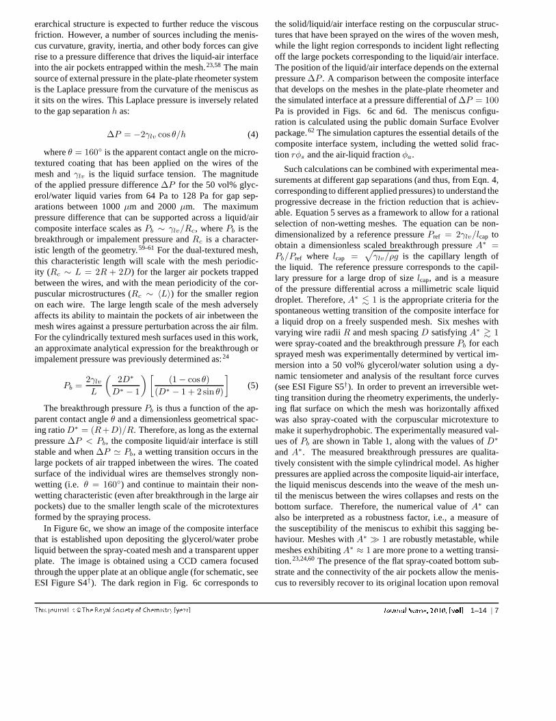
In Figure 9, we plot the ratio of the averaged viscosity mea-sured on a flat surface to that of the superhydrophobic meshηflat/ηmesh against the inverse gap-height1/h for a series offour meshes. A linear least squares fit of Eqn. 1 was per-formed to determine the mean slip lengths which are shown inTable 1, along with the predicted slip lengths (Eqn. 7) usingthe simulated wetted solid fractions calculated for each mesh.The dual textured meshes I to IV show a larger decrease in theapparent viscosity for a given height in the rheometer whencompared to the sprayed corpuscular structures discussed inthe first section. For a fixed wire radiusR = 127 µm, theslip length is observed to increase with mesh spacing, from〈bslip〉 ≈ 94 µm for Mesh II (D = 191 µm) to 〈bslip〉 ≈ 157µm for Mesh III (D = 326 µm). Upon further increasingthe mesh periodicity (Mesh V:R = 254, D = 805 µm,A∗ = 1.5), the effective slip length increases to〈bslip〉 ≈ 213µm but the mesh exhibits a lower robustness to the wettingtransition. The measured slip lengths on these spray-coatedmeshes are consistent with the analytical prediction forbmesh
obtained from Eqn. 7. The effect of meniscus sagging is mostevident for Mesh VI (A∗ = 1.0), for which ηflat/ηmesh < 1for h ≤ 1250 µm signifying enhanced drag when the liq-uid meniscus lies fully in between the features of the mesh.As shown in Fig. 9d, a systematic decrease in the ratio ofviscosities corresponding to enhanced frictional dissipation isobserved as the Laplace pressure drives the liquid further intothe mesh features at lower gap heights.
The variation of the effective slip lengths of the differentgeometries depends on the periodicity of the meshL and thewetted solid fractions via Eqn.7. In Figure 7, we plot the ra-tio of bslip/L against values of the wetted solid fractionrφs
(obtained from surface evolver simulations) for each of themeshes. The solid line corresponds to the prediction obtainedfrom Eqn. 7 and the dashed line is an alternate estimate of theslip length from Eqn. 3 which approximates the ellipsoidalwetted regions as a series of discrete circular patches.43,46De-spite the non-ideal topographic features of the woven meshsurface (i.e, fabrication tolerances, waviness and form drag),the model of Davis & Lauga given by Eqn. 7 captures the slowvariation of the experimentally-obtained slip values withthewetted solid fraction (calculated from Surface Evolver simu-lations) over the range of woven meshes used in our study. Weare able to generate maximum slip lengths of〈bslip〉 ≃ 213µmcorresponding to a friction reduction of30% for a gap of500µm. Our results indicate that giant liquid slip can onlybe obtained asrφs → 0, consistent with the work of Lee et
0.0 0.1 0.2 0.3 0.4 0.50.00
0.25
0.50
0.75
1.00
b slip/L
s
Woven Mesh Model Discrete Patches Model Mesh I Mesh II Mesh III Mesh IV Mesh V
Fig. 10 Ratio ofbslip/L plotted against the solid area fractionrφs
for Meshes I-V. The solid blue line and dashed red line correspondto the predictive curves forbwoven (from Eqn. 7) andbdiscrete(fromEqn. 3) respectively.
al15 who study post surfaces (withφs ≈ 1%). These large sliplengths can be achieved in woven meshes by judicious choiceof D∗ andL, as well as increasing the intrinsic non-wettabilityof the mesh coating. However, as we demonstrate in Eqn. 5and Fig. 10, such an increase in the slip length necessitatesatradeoff in the robustness of the mesh to a wetting transition.
4 Conclusions
In this work, we have demonstrated the friction reducing char-acteristics of a spray-coated fluorodecyl POSS/PMMA super-hydrophobic surface composed of randomly deposited corpus-cular microstructures. The effective slip length on the spray-coated surface was determined from rheometric force mea-surements involving a rational experimental design includingradial pinning of the liquid meniscus at the edge of the geom-etry, choice of operating shear rates and the use of multiplegap heights to address concerns over systematic errors suchasedge effects and potential inaccuracies in torque measurementassociated with this technique.37,38 The effective slip lengthon the sprayed microstructures was obtained using a weightedlinear least-squares fit asbslip ≈ 39 µm with a 95% upper-confidence interval of51 µm and a 95% lower-confidenceinterval of 28 µm with a reduction of drag ranging from 2-7 % corresponding to gap heights between 2000µm to 500µm. The mean periodicity and wetted area fraction was deter-mined from fluorescence microscopy and contact angle mea-surements as〈L〉 ≈ 32 µm andrφs ≈ 0.10 respectively. Theeffective slip length was observed to be qualitatively consis-
1–14 | 11
(a)
(c) (d)
(b)
Inverse gap height, 1/H (µm)-1
η#
at/η
me
sh
Fig. 9 Ratio of measured viscosity on a flat surface to the apparent viscosity measured on the friction reducing mesh plotted against theinverse gap height on the following spray-coated meshes surface: (a) Mesh II withR = 127µm andD = 191µm (b) Mesh III withR = 127µm andD = 326µm (c) Mesh V withR = 254µm andD = 805µm (d) Mesh VI withR = 127µm andD = 720µm. On the lattermesh, no friction reduction is observed due to a wetting transition; in fact the fully wetted Wenzel state results in an enhanced form drag. Theslip lengths for each mesh were extracted from a linear regression to Eqn. 1, and the dotted lines on each plot correspond to the 95%confidence bands.
Table 1The Mesh number, radius of the individual wire (R), half-spacing between the wire meshes (D), the dimensionless spacing ratioD∗ = (R +D)/R, the simulated wetted solid fraction (rφs), robustness factorA∗ ≈ Pb/Pref, experimental breakthrough pressurePb, theeffective slip length (bslip) determined from experiments and the prediction from the model of Davis & Lauga (bmesh, discussed in the maintext, see Eqn. 7) on the spray-coated woven meshes used in this work.
Mesh R D D∗ rφs A∗ Pb bslip bmesh
(µm) (µm) (Pa) (µm) (µm)I 70 229 4.3 0.17 4.99 - 92±10 122II 127 191 2.5 0.24 11.1 481 94±7 108III 127 326 3.6 0.25 4.4 180 157±14 149IV 254 452 2.8 0.40 4.1 112 194±24 157V 254 805 4.2 0.41 1.5 56 213±15 219VI 127 720 6.7 0.24 1.0 28 - 287
12 | 1–14

tent with that expected from a simple equivalent model of 2Dperiodic circular patches.
The larger intrinsic periodicityL in dual-scale sprayed su-perhydrophobic meshes can greatly increase the achievableslip length. We determined the effective slip length for a se-ries of spray-coated meshes and the extracted effective sliplength on the spray-coated meshes ranges between〈bslip〉 ≈94µm to 〈bslip〉 ≈ 213µm (see Table 1). The slow variationof thebslip is consistent with the prediction of Davis & Lauga,with the wetted solid fractionrφs for each mesh determinedfrom Surface Evolver simulations. By comparing the govern-ing equations for the slip length with a dimensionless expres-sion for robustness of the slip-inducing composite interface,we also have shown that the slip lengths of such composite in-terfaces have a strong inverse coupling with the robustnessofthe interface. This inverse correlation occurs because both theliquid slip and the robustness of the composite interface arescale-dependent properties, unlike static measures of super-hydrophobicity such as the effective advancing contact angleθ∗. The simplicity of the solution spraying process used in thepresent study is particularly helpful in facilitating rapid andcheap production of friction reducing coatings that can be ap-plied over large areas. When combined with periodic textures(such as woven meshes or post arrays) that can help supportthe composite vapour-liquid-solid interface (or plastron), verylarge slip lengths can be established.
5 Acknowledgments
We acknowledge financial support from the Army Re-search Office (ARO) through Contract W911NF-07-D-0004,the Naval Office of Research (ONR) through Contract3002452814, as well as the Air Force Research Laboratory,Propulsion Directorate, Air Force Office of Scientific Re-search. We thank Prof. Michael F. Rubner and the Institute forSoldier Nanotechnologies at MIT for the use of various labo-ratory facilities, Dr. Adam Meuler, Dr. Jonathan DeRocher,Justin Kleingartner and Hyomin Lee for helpful discussionsduring the preparation of this manuscript.
References
1 E. Lauga, M. Brenner and H. Stone, inMicrofluidics: The No-Slip Bound-ary Condition Springer Handbook of Experimental Fluid Mechanics, ed.C. Tropea, A. L. Yarin and J. F. Foss, Springer Berlin Heidelberg, 2007,pp. 1219–1240.
2 P. G. de Gennes,Langmuir, 2002,18, 3413–3414.3 J. P. Rothstein,Annual Review of Fluid Mechanics, 2010,42, 89–109.4 E. Lauga and H. A. Stone,Journal of Fluid Mechanics, 2003,489, 55–77.5 L. Bocquet and E. Lauga,Nat. Mater., 2011,10, 334–337.6 J. L. Barrat and L. Bocquet,Phys. Rev. Lett., 1999,82, 4671–4674.7 D. M. Huang, C. Sendner, D. Horinek, R. R. Netz and L. Bocquet, Phys.
Rev. Lett., 2008,101, 226101–1–226101–4.8 R. Pit, H. Hervet and L. Leger,Phys. Rev. Lett., 2000,85, 980–983.
9 R. S. Voronov, D. V. Papavassiliou and L. L. Lee,Industrial & Engineer-ing Chemistry Research, 2008,47, 2455–2477.
10 D. C. Tretheway and C. D. Meinhart,Phys. Fluids, 2002,14, L9–L12.11 L. Bocquet and J. L. Barrat,Soft Matter, 2007,3, 685–693.12 C. H. Choi, U. Ulmanella, J. Kim, C. M. Ho and C. J. Kim,Phys. Fluids,
2006,18, –.13 S. Gogte, P. Vorobieff, R. Truesdell, A. Mammoli, F. v. Swol, P. Shah and
C. J. Brinker,Phys. Fluids, 2005,17, 051701.14 C. Lee, C. H. Choi and C. J. Kim,Phys. Rev. Lett., 2008,101, –.15 C. Lee and C.-J. C. Kim,Langmuir, 2009,25, 12812–12818.16 G. McHale, N. J. Shirtcliffe, C. R. Evans and M. I. Newton,Appl. Phys.
Lett., 2009,94, –.17 J. Ou, B. Perot and J. P. Rothstein,Phys. Fluids, 2004,16, 4635–4643.18 J. Ou and J. P. Rothstein,Phys. Fluids, 2005,17, 103606–10.19 D. C. Tretheway and C. D. Meinhart,Phys. Fluids, 2004,16, 1509–1515.20 R. Truesdell, A. Mammoli, P. Vorobieff, F. van Swol and C. J. Brinker,
Phys. Rev. Lett., 2006,97, 044504.21 K. Watanabe, Yanuar and H. Udagawa,Journal of Fluid Mechanics, 1999,
381, 225–238.22 A. Cassie and S. Baxter,Transactions of Faraday Society, 1944, 40,
546551.23 A. Tuteja, W. Choi, M. L. Ma, J. M. Mabry, S. A. Mazzella, G. C. Rut-
ledge, G. H. McKinley and R. E. Cohen,Science, 2007,318, 1618–1622.24 S. S. Chhatre, W. Choi, A. Tuteja, K. C. Park, J. M. Mabry, G.H. McKin-
ley and R. E. Cohen,Langmuir, 2010,26, 4027–4035.25 C. F. Carlborg and W. van der Wijngaart,Langmuir, 2010,27, 487–493.26 C. H. Choi and C. J. Kim,Phys. Rev. Lett., 2006,96, –.27 J. Li, M. Zhou, L. Cai, X. Ye and R. Yuan,Chinese Science Bulletin,
2009,54, 4560–4565.28 Z. Ming, L. Jian, W. Chunxia, Z. Xiaokang and C. Lan,Soft Matter, 2011,
7, 4391–4396.29 N. J. Shirtcliffe, G. McHale, M. I. Newton and Y. Zhang,ACS Applied
Materials & Interfaces, 2009,1, 1316–1323.30 G. McHale, M. R. Flynn and M. I. Newton,Soft Matter, 2011,7, 10100–
10107.31 R. J. Daniello, N. E. Waterhouse and J. P. Rothstein,Phys. Fluids, 2009,
21, 085103–085112.32 M. A. Samaha, H. V. Tafreshi and M. Gad-el Hak,Phys. Fluids, 2011,23,
012001–8.33 M. Sbragaglia and A. Prosperetti,Journal of Fluid Mechanics, 2007,578,
435–451.34 F. Feuillebois, M. Z. Bazant and O. I. Vinogradova,Phys. Rev. Lett., 2009,
102, 026001.35 A. Yoshimura and R. K. Prud’homme,Journal of Rheology, 1988,32,
53–67.36 R. Bird, R. Armstrong and O. Hassager,Dynamics of polymeric liquids.
Vol. 1, 2nd Ed. : Fluid mechanics, 1987, p. Medium: X; Size: Pages: 784.37 L. Bocquet, P. Tabeling and S. Manneville,Phys. Rev. Lett., 2006,97, –.38 C. H. Choi and C. J. Kim,Phys. Rev. Lett., 2006,97, –.39 C. Lee and C.-J. Kim,Phys. Rev. Lett., 2011,106, 014502.40 J. R. Philip,Zeitschrift Fur Angewandte Mathematik Und Physik, 1972,
23, 353–372.41 K. Kamrin, M. Z. Bazant and H. A. Stone,Journal of Fluid Mechanics,
2010,658, 409–437.42 I. V. Olga and V. B. Aleksey,J. Phys.: Condens. Matter, 2011, 23,
184104.43 C. Ybert, C. Barentin, C. Cottin-Bizonne, P. Joseph and L.Bocquet,Phys.
Fluids, 2007,19, 123601–10.44 C.-O. Ng and C. Y. Wang,Phys. Fluids, 2009,21, 013602.45 C. Cottin-Bizonne, C. Barentin, . Charlaix, L. Bocquet and J. Barrat,The
European Physical Journal E: Soft Matter and Biological Physics, 2004,15, 427–438.
1–14 | 13

46 C.-O. Ng and C. Wang,Microfluidics and Nanofluidics, 2010,8, 361–371.47 A. M. J. Davis and E. Lauga,Journal of Fluid Mechanics, 2010,661,
402–411.48 J. Mabry, A. Vij, S. Iacono and B. Viers,Angewandte Chemie Interna-
tional Edition, 2008,47, 4137–4140.49 S. Srinivasan, S. S. Chhatre, J. M. Mabry, R. E. Cohen and G.H. McKin-
ley, Polymer, 2011,52, 3209–3218.50 C. J. Pipe, T. S. Majmudar and G. H. McKinley,Rheol. Acta, 2008,47,
621–642.51 C. Clasen, B. P. Gearing and G. H. McKinley,Journal of Rheology, 2006,
50, 883–905.52 G. A. Davies and J. R. Stokes,Journal of Rheology, 2005,49, 919–922.53 B. Costello, The AR-G2 Magnetic Bearing Rheometer, http:
//www.tainstruments.co.jp/application/pdf/Rheology_Library/Application_Briefs/RH085.pdf.
54 C. Macosko and R. Larson,Rheology: principles, measurements, andapplications, 1994.
55 M. Abramoff, P. Magalhaes and S. Ram,Biophotonics International,2004,11, 36–42.
56 T. An, S. J. Cho, W. Choi, J. H. Kim, S. T. Lim and G. Lim,Soft Matter,2011,7, 9867–9870.
57 L. Feng, Z. Zhang, Z. Mai, Y. Ma, B. Liu, L. Jiang and D. Zhu,Ange-wandte Chemie International Edition, 2004,43, 2012–2014.
58 D. Qur and M. Reyssat,Philosophical Transactions of the Royal Societya-Mathematical Physical and Engineering Sciences, 2008, 366, 1539–1556.
59 M. Reyssat, J. M. Yeomans and D. Qur,EPL (Europhysics Letters), 2008,81, 26006.
60 A. Tuteja, W. Choi, J. M. Mabry, G. H. McKinley and R. E. Cohen, Pro-ceedings of the National Academy of Sciences, 2008,105, 18200–18205h.
61 H.-J. Butt, C. Semprebon, P. Papadopoulos, D. Vollmer, M.Brinkmannand M. Ciccotti,Soft Matter, 2013,9, 418–428.
62 K. A. Brakke,Philosophical Transactions of the Royal Society of LondonSeries a-Mathematical Physical and Engineering Sciences, 1996, 354,2143–2157.
63 A. M. J. Davis and E. Lauga,Phys. Fluids, 2009,21, 113101.
14 | 1–14


![Second law analy - · PDF fileoceanography, geology, material sciences, ... Sahin [20], studied the entropy generation in a laminar viscous flow through a duct with constant wall](https://img.dokumen.tips/doc/110x75/5a78fb2e7f8b9a77088e20d4/second-law-analy-geology-material-sciences-sahin-20-studied-the-entropy.jpg)


![Atomization of viscous liquids Cooling Gas cooling · Spray Mode of Mixing Series VWater Application Page pattern liquid of fluids [l/h] supply](https://img.dokumen.tips/doc/110x75/606bbd1fefdf69233d57d662/atomization-of-viscous-liquids-cooling-gas-spray-mode-of-mixing-series-vwater-application.jpg)