Embed Size (px)
Citation preview
DRAFT VA DCR STORMWATER DESIGN SPECIFICATIONS No. 8: INFILTRATION
Infiltration of 23 9/18/081
DRAFT VA DCR STORMWATER DESIGN SPECIFICATION No. 8
INFILTRATION PRACTICESVERSION 1.5
Note to Reviewers of the Stormwater Design Specifications
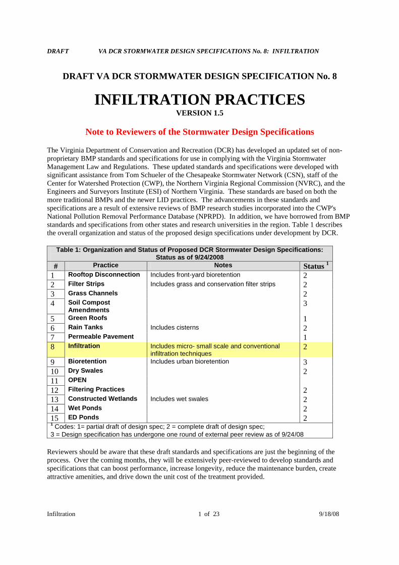
The Virginia Department of Conservation and Recreation (DCR) has developed an updated set of non-proprietary BMP standards and specifications for use in complying with the Virginia StormwaterManagement Law and Regulations. These updated standards and specifications were developed withsignificant assistance from Tom Schueler of the Chesapeake Stormwater Network (CSN), staff of theCenter for Watershed Protection (CWP), the Northern Virginia Regional Commission (NVRC), and theEngineers and Surveyors Institute (ESI) of Northern Virginia. These standards are based on both themore traditional BMPs and the newer LID practices. The advancements in these standards andspecifications are a result of extensive reviews of BMP research studies incorporated into the CWP'sNational Pollution Removal Performance Database (NPRPD). In addition, we have borrowed from BMPstandards and specifications from other states and research universities in the region. Table 1 describesthe overall organization and status of the proposed design specifications under development by DCR.
Table 1: Organization and Status of Proposed DCR Stormwater Design Specifications:Status as of 9/24/2008
# Practice Notes Status 1
1 Rooftop Disconnection Includes front-yard bioretention 22 Filter Strips Includes grass and conservation filter strips 23 Grass Channels 24 Soil Compost
Amendments3
5 Green Roofs 16 Rain Tanks Includes cisterns 27 Permeable Pavement 18 Infiltration Includes micro- small scale and conventional
infiltration techniques2
9 Bioretention Includes urban bioretention 310 Dry Swales 211 OPEN
12 Filtering Practices 213 Constructed Wetlands Includes wet swales 214 Wet Ponds 215 ED Ponds 21
Codes: 1= partial draft of design spec; 2 = complete draft of design spec;3 = Design specification has undergone one round of external peer review as of 9/24/08
Reviewers should be aware that these draft standards and specifications are just the beginning of theprocess. Over the coming months, they will be extensively peer-reviewed to develop standards andspecifications that can boost performance, increase longevity, reduce the maintenance burden, createattractive amenities, and drive down the unit cost of the treatment provided.
DRAFT VA DCR STORMWATER DESIGN SPECIFICATIONS No. 8: INFILTRATION
Infiltration of 23 9/18/082
Timeline for review and adoption of specifications and Role of the Virginia’s Stormwater BMPClearinghouse Committee:
The CSN will be soliciting input and comment on each standard and specification until the end of 2008from the research, design and plan review community. This feedback will ensure that these designstandards strike the right balance between prescription and flexibility, and that they work effectively ineach physiographic region. The collective feedback will be presented to the BMP ClearinghouseCommittee to help complement their review efforts. The Virginia Stormwater BMP ClearinghouseCommittee will consider the feedback and recommend final versions of these BMP standards andspecifications for approval by DCR.
The revisions to the Virginia Stormwater Management Regulations are not expected to become finalizeduntil late 2009. The DCR intends that these stormwater BMP standards and specifications will befinalized by the time the regulations become final.
The Virginia Stormwater BMP Clearinghouse Committee will consider the feedback and recommendfinal versions of these BMP standards and specifications for approval by DCR, which is vested by theCode of Virginia with the authority to determine what practices are acceptable for use in Virginia tomanage stormwater runoff.
As with any draft, there are several key caveats, as outlined below:
Many of the proposed design standards and specifications lack graphics. Graphics will be producedin the coming months, and some of graphics will be imported from the DCR 1999 VirginiaStormwater Management (SWM) Handbook. The design graphics shown in this current version aremeant to be illustrative. Where there are differences between the schematic and the text, the textshould be considered the recommended approach.
There are some inconsistencies in the material specifications for stone, pea gravel and filter fabricbetween ASTM, VDOT and the DCR 1999 SWM Handbook. These inconsistencies will be rectifiedin subsequent versions.
While the DCR 1999 SWM Handbook was used as the initial foundation for these draft standards andspecifications, additional side-by-side comparison will be conducted to ensure continuity.
Other inconsistencies may exist regarding the specified setbacks from buildings, roads, septicsystems, water supply wells and public infrastructure. These setbacks can be extremely important,and local plan reviewers should provide input to ensure that they strike the appropriate balancebetween risk aversion and practice feasibility.
These practice specifications will be posted in Wikipedia fashion for comment on the ChesapeakeStormwater Network’s web site at http://www.chesapeakestormwater.net, with instructions regarding howto submit comments, answers to remaining questions about the practice, useful graphics, etc. DCRrequests that you provide an email copy of your comments, etc., to Scott Crafton([email protected]). The final version will provide appropriate credit and attribution on thesources from which photos, schematics, figures, and text were derived.
Thank you for your help in producing the best stormwater design specifications for the Commonwealth.
DRAFT VA DCR STORMWATER DESIGN SPECIFICATIONS No. 8: INFILTRATION
Infiltration of 23 9/18/083
DRAFT VA DCR STORMWATER DESIGN SPECIFICATION No. 8
INFILTRATION PRACTICESVERSION 1.5
SECTION 1: DESCRIPTION
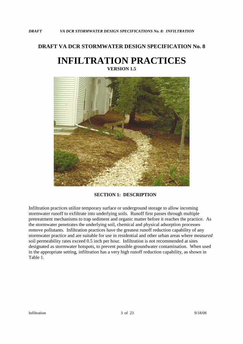
Infiltration practices utilize temporary surface or underground storage to allow incomingstormwater runoff to exfiltrate into underlying soils. Runoff first passes through multiplepretreatment mechanisms to trap sediment and organic matter before it reaches the practice. Asthe stormwater penetrates the underlying soil, chemical and physical adsorption processesremove pollutants. Infiltration practices have the greatest runoff reduction capability of anystormwater practice and are suitable for use in residential and other urban areas where measuredsoil permeability rates exceed 0.5 inch per hour. Infiltration is not recommended at sitesdesignated as stormwater hotspots, to prevent possible groundwater contamination. When usedin the appropriate setting, infiltration has a very high runoff reduction capability, as shown inTable 1.

DRAFT VA DCR STORMWATER DESIGN SPECIFICATIONS No. 8: INFILTRATION
Infiltration of 23 9/18/084
SECTION 2: PERFORMANCE CRITERIA
Table 1: Summary of Stormwater Functions Provided by InfiltrationStormwater Function Level 1 Design Level 2 Design
Annual Runoff Reduction 50% 90%Total Phosphorus Removal1
25% 25%
Total Nitrogen Removal 1 15% 15%Channel Protection Moderate
RRv can be subtracted from CPvFlood Mitigation Partial
Reduced Curve Numbers and Time of Concentration1 Change in event mean concentration (EMC) through the practice. Actual nutrient mass loadremoved is the product of the removal rate and the runoff reduction rate and will be higher thanthese percentages, as calculated using the Runoff Reduction Spreadsheet Methodology.Sources: CWP and CSN (2008) and CWP (2007).
SECTION 3: PRACTICE APPLICATIONS AND FEASIBILITY
Since infiltration practices have a very high runoff reduction capability, they should always beinitially considered when evaluating a site. Designers should evaluate the range of soilproperties during initial site layout and seek to configure the site to conserve and protect the soilswith the greatest recharge and infiltration rates. In particular, areas of Hydrologic Soil Group(HSG) A or B soils shown on NRCS soil surveys should be considered as primary locations forinfiltration practices. Designers should carefully analyze and define constraints on infiltration, asfollows:
Maximum Drainage Area: The contributing drainage area (CDA) to an individual infiltrationpractice should be less than 2 acres, and as close to 100% impervious as possible. Thisspecification covers three scales of infiltration practices: (1) Micro-infiltration (250 to 2500 sq.ft. of CDA); (2) small-scale infiltration (2500 to 20,000 sq. ft. of CDA); and (3) conventionalinfiltration (20,000 to 100,000 sq. ft. of CDA). The design, pretreatment, and maintenancerequirements differ depending on the scale at which infiltration is applied (summary in Table 3).
Site Slopes: Unless slope stability calculations demonstrate otherwise, infiltration practicesshould be located a minimum horizontal distance of 200 feet from down-gradient slopes greaterthan 20%. The average slope of the contributing drainage areas should be less than 15%.
Practice Slope: The bottom of an infiltration practice should be flat to enable even distributionand infiltration of stormwater (i.e., 0% longitudinal slope) although a maximum longitudinalslope of 1% is permissible if an underdrain is employed. Lateral slopes should be 0%.
Minimum Head: The elevation difference needed to operate a micro-scale infiltration practice isnominal, although 2 or more feet of head may be needed to drive small-scale and conventionalinfiltration practices.
DRAFT VA DCR STORMWATER DESIGN SPECIFICATIONS No. 8: INFILTRATION
Infiltration of 23 9/18/085
Minimum Depth to Water Table: A minimum vertical distance of 2 feet shall be providedbetween the bottom of the infiltration practice and the seasonal high water table or bedrock layer.
Soils: Native soils in proposed infiltration areas must have a minimum infiltration rate of 0.5inches per hour. Typically Hydrologic Soil Group (HSG) A and some B soils meet these criteria.Initially, projected soil infiltration rates can be estimated from NRCS soil data, but they must beconfirmed by an on-site infiltration evaluation. The silt/clay content of native soils must be lessthan 40%, and the clay content must be less than 20%.
Use on Urban Soils/Redevelopment Sites: Sites that have been previously graded or disturbeddo not retain their original soil permeability due to compaction. In addition, infiltration practicesshould never be situated above fill soils.
Dry Weather Flows: Infiltration practices should not be used on sites receiving regular dryweather flows from sump pumps, irrigation nuisance water, or other similar kinds of flows.
Setbacks: Infiltration practices should not be hydraulically connected to structure foundations orpavement, in order to avoid harmful seepage. Setbacks to structures and roads vary based on thescale of infiltration (see Table 3). At a minimum, conventional and small-scale infiltrationpractices should be located a minimum horizontal distance of 100 feet from any water supplywell, 50 feet from septic systems, and at least 5 feet downgradient from dry or wet utility lines.
High Loading Situations: Infiltration practices are not intended to treat sites with highsediment or trash/debris loads, since they will cause the practice to clog and fail.
Groundwater Protection: Section 4 of this specification presents a list of potential stormwaterhotspots that pose a risk of groundwater contamination. Infiltration of runoff from designatedhotspots is highly restricted or prohibited.
SECTION 4: ENVIRONMENTAL AND COMMUNITY ISSUES
4.1: Designation of Stormwater Hotspots
Stormwater hotspots are operations or activities that are known to produce higher concentrationsof stormwater pollutants and/or have a greater risk for spills, leaks, or illicit discharges. Table 2presents a list of potential land uses or operations that may be designated as a stormwaterhotspot. It should be noted that the actual hotspot generating area may only occupy a portion ofthe entire proposed use, and that some “clean” areas, such as rooftops, can be diverted away toanother infiltration or runoff reduction practice. Communities should carefully reviewdevelopment proposals to determine if future operations, in all or part of the site, will be need tobe designated as a stormwater hotspot. Based on this designation, one or more design responsesare required, as shown below:
1. Stormwater Pollution Prevention Plan (SWPPP). This plan is required as part of anindustrial or municipal stormwater permit. It outlines pollution prevention and treatmentpractices that will be implemented to minimize polluted discharges from the site. Other facilitiesor operations are not technically required to have NPDES permits, but may be designated as
DRAFT VA DCR STORMWATER DESIGN SPECIFICATIONS No. 8: INFILTRATION
Infiltration of 23 9/18/086
potential stormwater hotspots by the local review authority as part of the local stormwaterordinance (these are shown in the shaded areas of Table 2). It is recommended that thesefacilities include an addendum to their stormwater plans that details the pollution preventionpractices and employee training measures that will be used to reduce contact of pollutants withrainfall or snowmelt.
2. Restricted Infiltration. A minimum of 50% of the total Treatment Volume (Tv) must betreated by a filtering or bioretention practice prior to any infiltration. Portions of the site that arenot associated with the hotspot generating area should be diverted away and treated by anotheracceptable stormwater practice.
3. Infiltration Prohibition. The risk of groundwater contamination from spills, leaks, ordischarges is so great at these sites that infiltration of stormwater or snowmelt is prohibited.
Table 2: Potential Stormwater Hotspot and Site Design ResponsesPotential Stormwater Hotspot Operation SWPP Required? Restricted
InfiltrationNoInfiltration
Facilities w/NPDES Industrial permits Yes ■ ■Public works yard Yes ●Ports, shipyards and repair facilities Yes ●Railroads/ equipment storage Yes ●Auto and metal recyclers/scrapyards Yes ●Petroleum storage facilities Yes ●Highway maintenance facilities Yes ●Wastewater, solid waste, andcomposting facilities
Yes ●
Industrial machinery and equipment Yes ●Trucks and trailers Yes ●Airfields and aircraft maintenance areas Yes ●Fleet storage areas Yes ●Parking lots (40 or more parking spaces) No ●Gas stations No ●Highways (2500 ADT) No ●Construction business (paving, heavyequipment storage, and maintenance
No ●
Retail/wholesale vehicle/equipmentdealers
No ●
Convenience stores/fast food restaurants No ●Vehicle maintenance facilities No ●Car washes No ●Nurseries and garden centers No ●Golf courses No ●Notes:1. Gray-shaded rows indicate uses the locality may optionally designate as hotspots.
2. For a full list of potential stormwater hotspots, please consult Schueler et al (2004).Key: ■ depends on facility ● Yes
DRAFT VA DCR STORMWATER DESIGN SPECIFICATIONS No. 8: INFILTRATION
Infiltration of 23 9/18/087
4.2: Other Environmental and Community Issues
The following community and environmental concerns may arise when infiltration practices areproposed:
Nuisance Conditions: Poorly designed infiltration practices can create potential nuisanceproblems such as basement flooding, poor yard drainage, and standing water. In most cases,these problems can be minimized through the proper adherence to setback, soil testing, andpretreatment requirements outlined in this specification.
Mosquito Risks: Infiltration practices have some potential to create conditions favorable tomosquito breeding if they clog and have standing water for extended periods.
Groundwater Injection Permits: Groundwater injection permits are required if the infiltrationpractice is deeper than the longest surface area dimension of the practice (EPA, 2008).Designers should investigate whether or not a proposed infiltration practice is subject to a stateor local groundwater injection permit.
SECTION 5. DESIGN APPLICATIONS AND VARIATIONS
Infiltration practices may be applied to most land uses that have measured soil infiltration ratesthat exceed 0.5 inches per hour. However, there is no single infiltration application that fits allsituations. The nature of the actual design application depends on four key design factors,described below:
The first design factor to consider when applying infiltration to development sites is the scale atwhich it will be applied: micro-infiltration, small-scale infiltration, or conventional infiltration.Table 3 compares the different design approaches and requirements associated with eachinfiltration scale.
The second key design factor relates to the mode of temporarily storing runoff prior toinfiltration – either on the surface or in an underground trench. When storing runoff on thesurface (e.g., in an infiltration basin), the maximum depth should be no greater than 1 foot,unless pretreatment cells are used, in which case a maximum depth of 2 feet is permissible. Inthe underground mode, runoff is stored in the voids of the stones and infiltrates into theunderlying soil matrix. Perforated corrugated metal pipe, plastic arch pipe, plastic lattice trays,or comparable materials can be used in conjunction with stone to increase the availabletemporary underground storage. In some instances, a combination of filtration and infiltrationcells can be installed in the floor of a detention pond or a dry extended detention (ED) pond.
Table 3: The Three Design Scales for Infiltration PracticesDesign Factor Micro Infiltration Small-Scale
InfiltrationConventionalInfiltration
Impervious AreaTreated
250 to 2500 sq. ft. 2500 to 20,000 sq. ft. 20,000 to 100,000 sq. ft.

DRAFT VA DCR STORMWATER DESIGN SPECIFICATIONS No. 8: INFILTRATION
Infiltration of 23 9/18/088
Typical Practices Dry WellFrench DrainMicro BasinPaving Blocks
Infiltration TrenchPermeable Paving*
Infiltration TrenchInfiltration Basin
Runoff ReductionSizing
Minimum 0.1 inchesover CDA
Minimum 0.3 inchesover CDA
Remaining WQv up toFull Cpv
MinimumMeasured SoilInfiltration Rate
0.5 inches/hour 1.0 inches/hour 1.0 inches per hour
Design InfiltrationRate
50% of measured rate
Observation Well No Yes Yes
Type ofPretreatment
External (leafscreens, etc)
Filter strip or grasschannel
Pretreatment Cell
DepthDimensions
Max. 3 foot depth Max. 5 foot depth Max. 6 foot depth, checkOSHA
UIC PermitNeeded
No No Only if surface width isless than max. depth
HeadRequired
Nominal1-3 feet
Moderate1-5 feet
Moderate2-6 feet
UnderdrainRequirements?
Elevated underdrainonly on marginalsoils
Nonerequired
Back up underdrain
Required SoilBorings
One per practice Two per practice One per 500 sq. ft. ofproposed infiltrationarea
Building Setbacks 5 feet down-gradient25 feet up-gradient
10 feet down-gradient50 feet up-gradient
25 feet down-gradient100 feet up-gradient
* Although permeable pavement is an infiltration practice, a more detailed specification isprovided in Design Specification No. 5
The third design factor relates to the degree of confidence that exfiltration can be maintainedover time, given the measured infiltration rate for the subsoils at the practice site. Thisdetermines whether an underdrain or an alternative practice, such as bioretention, is needed (seeTable 4).
The final factor is whether the infiltration practice will be designed as an on-line or off-linefacility, since this determines the nature of conveyance and overflows needed. On-lineinfiltration practices may be connected to underground perforated pipes to detain the peak stormevent, or have suitable overflows to pass the storms without erosion. Off-line practices are sizedto only accept some portion of the Treatment Volume and employ a flow splitter to safely bypasslarge storms.
DRAFT VA DCR STORMWATER DESIGN SPECIFICATIONS No. 8: INFILTRATION
Infiltration of 23 9/18/089
Table 4: Design Choices Based on Measured Infiltration RateMeasured Infiltration Rate (inches/hour)
Less than 0.5 0.5 to 1.0 1.0 to 4.0 More than 4RecommendedDesignSolution
Use Bioretentionwith underdrain
Use Infiltration,and investigateelevatedunderdrain
Use Infiltration Use Bioretentionwithoutunderdrain
SECTION 6: SIZING AND TESTING GUIDANCE
6.1: Defining the Infiltration Rate
Soil permeability is the single biggest factor when evaluating infiltration practices. A minimuminfiltration rate of at least 0.5 inches/hour is needed to make the practice work.
Projected infiltration rate: For planning purposes, the projected infiltration rate for the site canbe estimated using the SCS soil textural triangle for the prevailing soil types indicated on thelocal NRCS Soil Survey. This data is solely used to locate portions of the site where infiltrationmay be feasible and to pinpoint where actual on-site infiltration tests will be taken to confirmfeasibility.
Measured Infiltration rate: On-site infiltration investigations should always be conducted toestablish the actual infiltration capacity of underlying soils. Methods to do so are presented inAppendix A.
Design Infiltration rate: Several studies have shown that ultimate infiltration rates decline by asmuch as 50% from initial rates, so designers should be very conservative and not forceinfiltration on questionable soils. Therefore, the infiltration rate used in design shall be 50% ofthe measured rate.
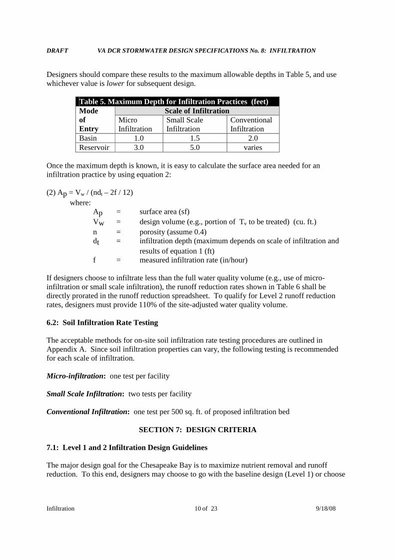
6.2: Overall Sizing
Several equations are needed to size infiltration practices. The first equations establish themaximum depth of the infiltration practice, depending on whether it is a surface or undergroundreservoir.
(1.1) Basin dmax = ½ f * Tmax
‘(1.2) Underground Reservoir dmax = ½ f * Tmax / Vr
where:Dmax = maximum depth of the infiltration practice (feet)f = measured infiltration rate (in/hour)Tmax = maximum drawn down time (normally 36 to 48 hours)Vr = void ratio of the stone reservoir (usually 0.4)
DRAFT VA DCR STORMWATER DESIGN SPECIFICATIONS No. 8: INFILTRATION
Infiltration of 23 9/18/0810
Designers should compare these results to the maximum allowable depths in Table 5, and usewhichever value is lower for subsequent design.
Table 5. Maximum Depth for Infiltration Practices (feet)Scale of InfiltrationMode
ofEntry
MicroInfiltration
Small ScaleInfiltration
ConventionalInfiltration
Basin 1.0 1.5 2.0Reservoir 3.0 5.0 varies
Once the maximum depth is known, it is easy to calculate the surface area needed for aninfiltration practice by using equation 2:
(2) Ap = Vw / (ndt – 2f / 12)
where:Ap = surface area (sf)
Vw = design volume (e.g., portion of Tv to be treated) (cu. ft.)
n = porosity (assume 0.4)dt = infiltration depth (maximum depends on scale of infiltration and
results of equation 1 (ft)f = measured infiltration rate (in/hour)
If designers choose to infiltrate less than the full water quality volume (e.g., use of micro-infiltration or small scale infiltration), the runoff reduction rates shown in Table 6 shall bedirectly prorated in the runoff reduction spreadsheet. To qualify for Level 2 runoff reductionrates, designers must provide 110% of the site-adjusted water quality volume.
6.2: Soil Infiltration Rate Testing
The acceptable methods for on-site soil infiltration rate testing procedures are outlined inAppendix A. Since soil infiltration properties can vary, the following testing is recommendedfor each scale of infiltration.
Micro-infiltration: one test per facility
Small Scale Infiltration: two tests per facility
Conventional Infiltration: one test per 500 sq. ft. of proposed infiltration bed
SECTION 7: DESIGN CRITERIA
7.1: Level 1 and 2 Infiltration Design Guidelines
The major design goal for the Chesapeake Bay is to maximize nutrient removal and runoffreduction. To this end, designers may choose to go with the baseline design (Level 1) or choose
DRAFT VA DCR STORMWATER DESIGN SPECIFICATIONS No. 8: INFILTRATION
Infiltration of 23 9/18/0811
an enhanced Level 2 that maximizes nutrient and runoff reduction. To qualify for Level 2, theinfiltration practice must meet all design criteria shown in the right hand column of Table 6.
Table 6: Level 1 and Level 2 Infiltration Design GuidelinesLevel 1 Design (RR:50; TP:25; TN:15) Level 2 Design (RR:90; TP:25; TN:15)TV= (1)(Rv)(A) / 12 TV= (1.1)(Rv)(A) / 12Maximum CDA of 1 acre Max CDA of 0.5 acre, nearly 100% ICAt least two forms of pretreatment At least three forms of pretreatmentSoil infiltration rate of 0.5 to 1.0 in/hr Soil infiltration rates of 1.0 to 4.0 in/hrUnderdrain needed due to soils No underdrain utilized, although elevated
underdrain may be used on C and DAll Designs are subject to hotspot runoff restrictions/prohibitions.
7.2: Pretreatment Features
Every infiltration practice must include multiple pretreatment techniques, although the nature ofpretreatment practices depends on the scale at which infiltration is applied. The number,volume, and type of acceptable pretreatment techniques needed for the three scales of infiltrationare provided in Table 7.
Table 7: Required Pretreatment Elements for Infiltration PracticesScale of InfiltrationPretreatment 1
MicroInfiltration
Small ScaleInfiltration
ConventionalInfiltration
Number andVolume ofPretreatment
2 external techniques,no minimumpretreatmentvolume required
3 techniques, 15%minimumpretreatment volumerequired (inclusive)
3 techniques, 25%minimum pretreatmentvolume required(inclusive)At least one separate pre-treatment cell
AcceptablePretreatmentTechniques
Leaf gutter screensGrass bufferUpper sand layerWashed bank rungravel
Grass filter stripGrass channelPlunge poolPea gravel diaphragm
Sediment trap cellSand filter cellSump pitGrass channel of filterstrip
1 A minimum of 50% of the runoff reduction volume must be pre-treated by a filtering orbioretention practice prior to infiltration if the site is a restricted stormwater hotspot.
Note that conventional infiltration practices require pretreatment of at least 25% of the treatmentvolume, including a surface pretreatment cell capable of keeping sediment and vegetation out ofthe infiltration cell. All pretreatment practices should be designed such that exit velocities arenon-erosive for the 2-year design storm and evenly distribute flows across the width of thepractice (e.g., using a level spreader).

DRAFT VA DCR STORMWATER DESIGN SPECIFICATIONS No. 8: INFILTRATION
Infiltration of 23 9/18/0812
7.3: Conveyance and Overflow
The nature of the conveyance and overflow to an infiltration practice depends on the scale ofinfiltration and whether the facility is on-line or off-line (Table 8). Where possible, conventionalinfiltration practices should be designed offline to avoid damage from the erosive velocities oflarger design storms. Micro-scale and small-scale infiltration practices shall be designed tomaintain non-erosive conditions for overland flows generated by the 2-year design storm(typically 3.5 to 5.0 feet per second).
Table 8: Conveyance and Overflow Choices Based on Infiltration ScaleScale of InfiltrationConveyance and
Overflow MicroInfiltration
Small ScaleInfiltration
ConventionalInfiltration
Online Design Non-erosive perviousoverland flow path tostreet or storm drainsystem for two yeardesign storm
An overflow mechanism such as a elevateddrop inlet or flow splitter should be used toredirect flows to an overflow channel orstabilized water course. Non-erosive downslope overflows for ten year design event
Off-line DesignNor Recommended
A flow splitter or overflow structure can beused for this purpose using design guidance inClaytor and Schueler (1996) and ARC (2001).
7.4: Internal Geometry and Drawdowns
Runoff Reduction Volume Sizing: The design approach for infiltration is to not force a largeamount of infiltration into a small area. Individual infiltration practices need not be sized toachieve the full water quality volume, as long as other runoff reduction practices are applied atthe site to meet the remainder. The total runoff reduction volume shall be documented using theVA DCR runoff reduction spreadsheet or another locally-approved methodology that achievesequivalent results. The minimum amount of runoff that can be treated in individual practices isbased on the scale of infiltration, as described below:
Micro-infiltration: Minimum 0.1 inches over the CDA
Small-scale Infiltration: Minimum 0.3 inches over the CDA
Conventional Infiltration: Remaining Treatment Volume from the CDA
(NOTE: Clarify whether the measurements above refer to the depth of rainfall or depth ofrunoff over the CDA.)
Elevated Underdrain: To promote greater runoff reduction for infiltration practices located onsoils with marginal permeability, an elevated underdrain should be installed with a stone jacketthat creates a 12-18 inch deep storage layer below the underdrain invert. The void storage in thislayer can help qualify a site to achieve Level 2 design.
DRAFT VA DCR STORMWATER DESIGN SPECIFICATIONS No. 8: INFILTRATION
Infiltration of 23 9/18/0813
Infiltration Basin Restrictions: The maximum vertical depth to which runoff may be pondedover an infiltration area is 24 inches (i.e., infiltration basin). The side-slopes should be4:1 (H:V) or gentler. If the basin serves a CDA greater than 20,000 sq. ft., a surface pretreatmentcell must be provided. This may be a sand filter or dry sediment basin.
Rapid Drawdown: When possible, infiltration practices should be sized so that the target runoffreduction volume infiltrates within 36-48 hours to provide a factor of safety that preventsnuisance ponding conditions.
Conservative Infiltration Rates: Designers should always use the design infiltration rate ratherthan the measured infiltration rate to approximate long-term infiltration rates (see Section 6.1).
Void Ratio: A porosity value of 0.40 shall be used in the design of stone reservoirs, although alarger value may be used if perforated corrugated metal pipe, plastic arch pipe, or plastic latticetrays are provided in the reservoir.
7.5: Landscaping and Safety
Infiltration trenches can be effectively integrated into the site planning process and aestheticallydesigned with adjacent native landscaping or turf cover, subject to the following additionaldesign considerations:
Infiltration practices should NEVER be installed until all upgradient construction iscompleted AND pervious areas are stabilized with dense and healthy vegetation.
Vegetation associated with the infiltration buffers should be regularly mowed and maintainedto keep organic matter out and maintain enough native vegetation to prevent soil erosionfrom occurring.
Infiltration practices do not pose any major safety hazards after construction. However, if aninfiltration practice will be excavated to a depth greater than 5 feet, OSHA health and safetyguidelines for safe construction practices need to be consulted.
Fencing of infiltration trenches is neither necessary nor desirable.
Designers should always evaluate the nature of future operations to determine if the proposedsite will be designated as a potential stormwater hotspot (see Section 4.1) and should complywith the appropriate restrictions or prohibitions on infiltration.
7.6: Maintenance Reduction Features
Maintenance is a crucial element to ensuring the long-term performance of infiltration practices.The most frequently cited maintenance problem for infiltration practices is clogging caused byorganic matter and sediment. The following design features can minimize the risk of clogging:
DRAFT VA DCR STORMWATER DESIGN SPECIFICATIONS No. 8: INFILTRATION
Infiltration of 23 9/18/0814
Observation Well: Small scale and conventional infiltration practices should include anobservation well consisting of an anchored six-inch diameter perforated PVC pipe fitted with alockable cap installed flush with the ground surface to facilitate periodic inspection andmaintenance.
No Filter Fabric on Bottom: The use of geotextile filter fabric along the bottom of infiltrationpractices should be avoided. Experience has shown that filter fabric is prone to clogging, and thata layer of coarse washed stone (choker stone) is a more effective substitute. Permeable filterfabric shall be installed on the trench sides to prevent soil piping.
Direct Maintenance Access: Access shall be provided to allow crews and heavy equipment toperform non-routine maintenance tasks, such as practice reconstruction or rehabilitation. Whilea turf cover is permissible for micro and small-scale infiltration, the surface must never becovered by an impermeable material, such as asphalt or concrete.
SECTION 8: REGIONAL AND CLIMATE DESIGN ADAPTATIONS
8.1: Karst Terrain
Conventional infiltration practices should not be used in active karst regions due to concernsabout sinkhole formation and groundwater contamination. Micro or small-scale infiltration areasare permissible IF geotechnical studies indicate at least 4 feet of vertical separation existsbetween the bottom of these facilities and the underlying active karst layer, AND animpermeable liner and underdrain are used. In many cases, bioretention is a preferredstormwater alternative to infiltration in karst areas.
8.2: Coastal Plain
The flat terrain, low head and high water table of many coastal plain sites can constrain theapplication of conventional infiltration practices. However, such sites are still suited for micro-infiltration and small-scale infiltration practices. Designers should maximize the surface area ofthe infiltration practice and keep the depth of infiltration to less than 24 inches. Where soils areextremely permeable (more than 4.0 inches per hour), shallow bioretention is a preferredalternative. Where soils are more impermeable (e.g., marine clays with less than 0.5inches/hour), designers may prefer to use a constructed wetland practice.
8.3: Steep Terrain
Forcing conventional infiltration practices in steep terrain can be problematic with respect toslope stability, excessive hydraulic gradients, and sediment delivery. It is generallyrecommended that, unless slope stability calculations demonstrate otherwise, infiltrationpractices should be located a minimum horizontal distance of 200 feet from down-gradientslopes greater than 20%. Micro-infiltration and small-scale infiltration can work well as long astheir smaller up-gradient and down-gradient building setbacks are satisfied.
DRAFT VA DCR STORMWATER DESIGN SPECIFICATIONS No. 8: INFILTRATION
Infiltration of 23 9/18/0815
8.4: Winter Performance
Infiltration practices are generally not feasible in extremely cold climates where permafrostexists, but they can be designed to withstand more moderate winter conditions. The mainproblem is caused by ice forming in the voids or the subsoils below the practice, which maybriefly result in nuisance flooding when spring melt occurs. The following design adjustmentsare recommended for infiltration practices installed where such conditions exist:
The bottom of the practice should extend below the frost line.
Infiltration practices are not recommended at roadside locations that are heavily sandedand/or salted in the winter months (to prevent movement of chlorides into groundwater andprevent clogging by road sand).
Pretreatment measures can be oversized to account for the additional sediment load causedby road sanding (up to 40% of the Tv).
Infiltration practices must be set back at least 25 feet from roadways to prevent potential frostheaving of road pavements.
8.5: Linear Highway Sites
Infiltration practices can work well at linear highway projects where soils are suitable and can beprotected from heavy disturbance and compaction during road construction operations.
DRAFT VA DCR STORMWATER DESIGN SPECIFICATIONS No. 8: INFILTRATION
Infiltration of 23 9/18/0816
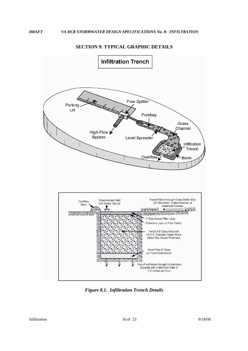
SECTION 9: TYPICAL GRAPHIC DETAILS
Figure 8.1. Infiltration Trench Details
DRAFT VA DCR STORMWATER DESIGN SPECIFICATIONS No. 8: INFILTRATION
Infiltration of 23 9/18/0817
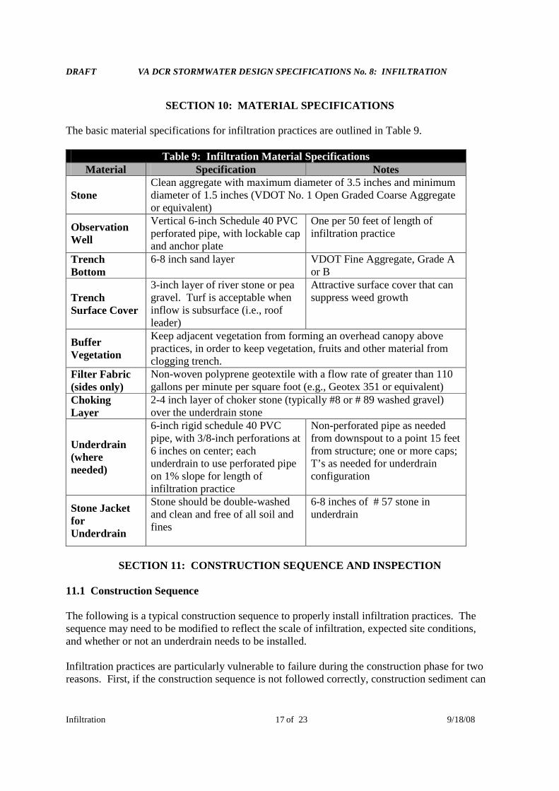
SECTION 10: MATERIAL SPECIFICATIONS
The basic material specifications for infiltration practices are outlined in Table 9.
Table 9: Infiltration Material SpecificationsMaterial Specification Notes
StoneClean aggregate with maximum diameter of 3.5 inches and minimumdiameter of 1.5 inches (VDOT No. 1 Open Graded Coarse Aggregateor equivalent)
ObservationWell
Vertical 6-inch Schedule 40 PVCperforated pipe, with lockable capand anchor plate
One per 50 feet of length ofinfiltration practice
TrenchBottom
6-8 inch sand layer VDOT Fine Aggregate, Grade Aor B
TrenchSurface Cover
3-inch layer of river stone or peagravel. Turf is acceptable wheninflow is subsurface (i.e., roofleader)
Attractive surface cover that cansuppress weed growth
BufferVegetation
Keep adjacent vegetation from forming an overhead canopy abovepractices, in order to keep vegetation, fruits and other material fromclogging trench.
Filter Fabric(sides only)
Non-woven polyprene geotextile with a flow rate of greater than 110gallons per minute per square foot (e.g., Geotex 351 or equivalent)
ChokingLayer
2-4 inch layer of choker stone (typically #8 or # 89 washed gravel)over the underdrain stone
Underdrain(whereneeded)
6-inch rigid schedule 40 PVCpipe, with 3/8-inch perforations at6 inches on center; eachunderdrain to use perforated pipeon 1% slope for length ofinfiltration practice
Non-perforated pipe as neededfrom downspout to a point 15 feetfrom structure; one or more caps;T’s as needed for underdrainconfiguration
Stone JacketforUnderdrain
Stone should be double-washedand clean and free of all soil andfines
6-8 inches of # 57 stone inunderdrain
SECTION 11: CONSTRUCTION SEQUENCE AND INSPECTION
11.1 Construction Sequence
The following is a typical construction sequence to properly install infiltration practices. Thesequence may need to be modified to reflect the scale of infiltration, expected site conditions,and whether or not an underdrain needs to be installed.
Infiltration practices are particularly vulnerable to failure during the construction phase for tworeasons. First, if the construction sequence is not followed correctly, construction sediment can
DRAFT VA DCR STORMWATER DESIGN SPECIFICATIONS No. 8: INFILTRATION
Infiltration of 23 9/18/0818
clog the practice. Second, heavy construction can result in compaction of the soil, which canthen reduce the soil’s infiltration rate. For this reason, a careful construction sequence needs tobe followed.
During site construction, the following steps are absolutely critical:
Avoid excessive compaction by preventing construction equipment and vehicles fromtraveling over the proposed location of the infiltration practice.
Keep the infiltration practice “off-line” until construction is complete. Sediment shall beprevented from entering the infiltration site by using super silt fence, diversion berms, orother means. The erosion and sediment control plan shall indicate the earliest point at whichstorm runoff may be directed to a conventional infiltration basin and the specific means bywhich the delay in runoff shall be accomplished.
Infiltration practices should never serve as a sediment control device during site construction.
Upland drainage areas need to be completely stabilized with a thick layer of vegetation priorto commencing excavation of an infiltration practice, as verified by the local erosion andsediment control inspector/program.
The actual installation of an infiltration practice is done using the following steps:
1. Excavate the infiltration practice to design dimensions from the side using a backhoe orexcavator. The floor of the pit should be completely level.
2. Correctly install filter fabric on trench sides. Large tree roots should be trimmed flush withthe sides of infiltration trenches to prevent puncturing or tearing of the filter fabric duringsubsequent installation procedures. When laying out the geotextile, the width should includesufficient material to compensate for perimeter irregularities in the trench and for a 6-inchminimum overlap at the top of the trench. The filter fabric itself should be tucked under the sandlayer on the bottom of the infiltration trench, and stones or other anchoring objects should beplaced on the fabric at the trench sides to keep the trench open during windy periods. Voids mayoccur between the fabric and the excavated sides of a trench. Natural soils should be placed inall voids to ensure the fabric conforms to the sides of the excavation.
3. Scarify the bottom of the infiltration practice, and spread 6 inches of sand for the bottom filterlayer.
4. Install the underdrain, if one is needed.
5. Anchor the observation well and add stone to the practice in 1-foot lifts.
6. Use sod to establish dense turf cover 10 feet on each side of the infiltration practice to reduceerosion and sloughing. If seeding instead, native grasses is are recommended primarily due totheir adaptability to local climate and soil conditions.

DRAFT VA DCR STORMWATER DESIGN SPECIFICATIONS No. 8: INFILTRATION
Infiltration of 23 9/18/0819
11.2: Construction Inspection
Inspections during construction are needed to ensure that the infiltration practice is built inaccordance with the approved design and standards and specifications. Qualified individualsshould use detailed inspection checklists that include sign-offs at critical stages of construction toensure that the contractor’s interpretation of the plan is acceptable to the designer. An exampleconstruction phase inspection checklist for infiltration practices can be accessed at the CWPwebsite at
http://www.cwp.org/Resource_Library/Center_Docs/SW/pcguidance/Tool6.pdf
SECTION 12: OPERATION AND MAINTENANCE
12.1: Maintenance Agreements
A legally binding and enforceable maintenance agreement should be executed between thepractice owner and the local review authority. The agreement should specify the municipality’sright of entry and guarantee adequate access for inspection, maintenance, and landscapingupkeep of the infiltration practice(s). The maintenance agreements must contain recommendedmaintenance tasks and a copy of an annual inspection checklist. When micro or small-scaleinfiltration practices are applied on private residential lots, homeowners will need to be educatedon their routine maintenance needs, understand the long-term maintenance plan, and be subjectto a legally binding maintenance agreement that is transferable to new owners upon sale. Inaddition, the GPS coordinates for all infiltration practices shall be provided upon facilityacceptance to ensure long-term tracking.
12.2: Maintenance Inspections
Annual site inspections are critical to the performance and longevity of infiltration practices,particularly for small-scale and conventional infiltration practices. Maintenance of infiltrationpractices is driven by annual inspections that evaluate the condition and performance of thepractice (see Table 10). Based on inspection results, specific maintenance tasks will betriggered. An annual maintenance inspection form for infiltration practices can be accessed atthe CWP website at
http://www.cwp.org/Resource_Library/Center_Docs/SW/pcguidance/Tool6.pdf
12.3: Ongoing Maintenance
Effective long-term operation of infiltration practices requires a dedicated and routinemaintenance inspection schedule with clear guidelines and schedules, as shown in Table 11.Where possible, facility maintenance should be integrated into routine landscaping maintenancetasks.
DRAFT VA DCR STORMWATER DESIGN SPECIFICATIONS No. 8: INFILTRATION
Infiltration of 23 9/18/0820
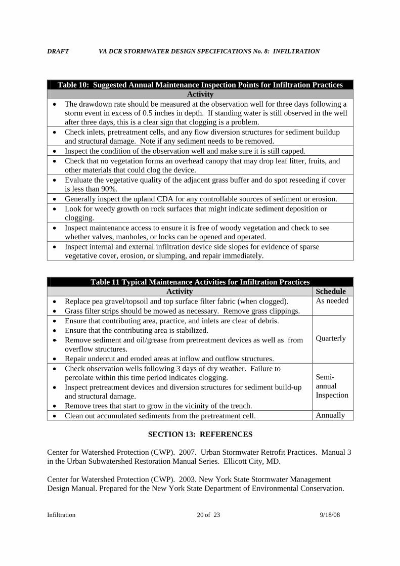
Table 10: Suggested Annual Maintenance Inspection Points for Infiltration PracticesActivity
The drawdown rate should be measured at the observation well for three days following astorm event in excess of 0.5 inches in depth. If standing water is still observed in the wellafter three days, this is a clear sign that clogging is a problem.
Check inlets, pretreatment cells, and any flow diversion structures for sediment buildupand structural damage. Note if any sediment needs to be removed.
Inspect the condition of the observation well and make sure it is still capped.
Check that no vegetation forms an overhead canopy that may drop leaf litter, fruits, andother materials that could clog the device.
Evaluate the vegetative quality of the adjacent grass buffer and do spot reseeding if coveris less than 90%.
Generally inspect the upland CDA for any controllable sources of sediment or erosion.
Look for weedy growth on rock surfaces that might indicate sediment deposition orclogging.
Inspect maintenance access to ensure it is free of woody vegetation and check to seewhether valves, manholes, or locks can be opened and operated.
Inspect internal and external infiltration device side slopes for evidence of sparsevegetative cover, erosion, or slumping, and repair immediately.
Table 11 Typical Maintenance Activities for Infiltration PracticesActivity Schedule
Replace pea gravel/topsoil and top surface filter fabric (when clogged). Grass filter strips should be mowed as necessary. Remove grass clippings.
As needed
Ensure that contributing area, practice, and inlets are clear of debris. Ensure that the contributing area is stabilized. Remove sediment and oil/grease from pretreatment devices as well as from
overflow structures. Repair undercut and eroded areas at inflow and outflow structures.
Quarterly
Check observation wells following 3 days of dry weather. Failure topercolate within this time period indicates clogging.
Inspect pretreatment devices and diversion structures for sediment build-upand structural damage.
Remove trees that start to grow in the vicinity of the trench.
Semi-annualInspection
Clean out accumulated sediments from the pretreatment cell. Annually
SECTION 13: REFERENCES
Center for Watershed Protection (CWP). 2007. Urban Stormwater Retrofit Practices. Manual 3in the Urban Subwatershed Restoration Manual Series. Ellicott City, MD.
Center for Watershed Protection (CWP). 2003. New York State Stormwater ManagementDesign Manual. Prepared for the New York State Department of Environmental Conservation.

DRAFT VA DCR STORMWATER DESIGN SPECIFICATIONS No. 8: INFILTRATION
Infiltration of 23 9/18/0821
Delaware Urban Runoff Management Approachhttp://www.dnrec.state.de.us/DNREC2000/Divisions/Soil/Stormwater/New/GT_Stds%20&%20Specs_06-05.pdf
Maryland Department of Environment (MDE). 2000. Maryland Stormwater Design Manual.Baltimore, MD.
New Jersey Stormwater Best Management Practices Manualhttp://www.nj.gov/dep/watershedmgt/bmpmanualfeb2004.htm
North Shore City 2007. Infiltration Design Guidelines. Sinclair, Knight and Merz. Auckland,New Zealand.
Pennsylvania Draft Stormwater Best Management Practices Manualhttp://www.dep.state.pa.us/dep/subject/advcoun/Stormwater/stormwatercomm.htm
Schueler, T., C. Swann, T. Wright and S. Sprinkle. 2004. Pollution source control practices.Manual No. 8 in the Urban Subwatershed Restoration Manual Series. Center for WatershedProtection. Ellicott City, MD.
Virginia Department of Conservation and Recreation (VA DCR). 1999. Virginia StormwaterManagement Handbook. Volumes 1 and 2. Division of Soil and Water Conservation. Richmond,VA.
DRAFT VA DCR STORMWATER DESIGN SPECIFICATIONS No. 8: INFILTRATION
Infiltration of 23 9/18/0822
APPENDIX A: INFILTRATION TESTING PROCEDURES
On-site testing should be conducted to establish the infiltration capacity of the native soils anddetermine the feasibility of infiltration. This appendix presents a basic infiltration testingprocedure that can be used to determine soil infiltration rates at a development site.
Test Pit/Boring Procedures
1. One test pit or standard soil boring should be provided for every 250 sq. ft. of the proposedinfiltration area.
2. The location of each test pit or standard soil boring should correspond to the location of theproposed infiltration area.
3. Excavate each test pit or dig each standard soil boring to a depth at least 2 feet below thebottom of the proposed infiltration area.
4. If the groundwater table is located within 2 feet of the bottom of the proposed facility,determine the depth to the groundwater table immediately upon excavation and again 24hours after excavation.
5. Conduct Standard Penetration Testing (SPT) every 2 feet to a depth that is 2 feet below thebottom of the proposed infiltration area.
6. Determine the USDA or Unified Soil Classification system textures at the bottom of theproposed infiltration area and at a depth that is 2 feet below the bottom. All soil horizonsshould be classified and described.
7. If bedrock is located within 2 feet of the bottom of the proposed area, determine the depth tothe bedrock layer.
8. Test pit/soil boring stakes should be left in the field to identify where soil investigations wereperformed.
Infiltration Testing Procedures
1. One infiltration test should be provided for every 250 square feet of surface area of theinfiltration area.
2. The location of each infiltration test should correspond to the location of the proposedinfiltration area.
3. Install a test casing (e.g., rigid, 4-6 inch diameter pipe) to a depth 2 feet below the bottom ofthe proposed infiltration area.

DRAFT VA DCR STORMWATER DESIGN SPECIFICATIONS No. 8: INFILTRATION
Infiltration of 23 9/18/0823
4. Remove all loose material from sides of the test casing and any smeared soil surfaces fromthe bottom of the test casing to provide a natural soil interface into which water maypercolate. If desired, a 2-inch layer of coarse sand or fine gravel may be placed at the bottomof the test casing to prevent clogging and scouring of the underlying soils. Fill the test casingwith clean water to a depth of 2 feet and allow the underlying soils to pre-soak for 24 hours.
5. After 24 hours later, refill the test casing with another 2 feet of clean water and measure thedrop in water level within the test casing after 1 hour. Repeat the procedure three additionaltimes by filling the test casing with clean water and measuring the drop in water level after 1hour. A total of four observations must be completed. The infiltration rate of the underlyingsoils may either be reported as the average of all four observations or the value of the lastobservation. The infiltration rate should be reported terms of in inches per hour.
6. Infiltration testing may be performed within an open test pit or a standard soil boring.
7. After infiltration testing is completed, the test casing should be removed and the test pit orsoil boring should be backfilled and restored.