Embed Size (px)
Citation preview

Draft NISTIR 8320B 1 2
Hardware-Enabled Security: 3
Policy-Based Governance in Trusted Container Platforms 4
5 Michael Bartock 6
Murugiah Souppaya 7 Haidong Xia 8
Raghu Yeluri 9 Uttam Shetty 10
Brandon Lum 11 Mariusz Sabath 12 Harmeet Singh 13
Alaa Youssef 14 Gosia Steinder 15
Yu Cao 16 Jayashree Ramanathan 17
18 19
20 This publication is available free of charge from: 21
https://doi.org/10.6028/NIST.IR.8320B-draft 22 23

Draft NISTIR 8320B 24 25
Hardware-Enabled Security: 26
Policy-Based Governance in Trusted Container Platforms 27 28 29
Michael Bartock Murugiah Souppaya
Computer Security Division Information Technology Laboratory
Brandon Lum Mariusz Sabath Harmeet Singh
Alaa Youssef Gosia Steinder
IBM Armonk, New York
Haidong Xia
Raghu Yeluri Uttam Shetty
Intel Corporation Santa Clara, California
Yu Cao Jayashree Ramanathan
Red Hat Raleigh, North Carolina
30 31
This publication is available free of charge from: 32 https://doi.org/10.6028/NIST.IR.8320B-draft 33
34 October 2021 35
36
37 38
U.S. Department of Commerce 39 Gina M. Raimondo, Secretary 40
41 National Institute of Standards and Technology 42
James K. Olthoff, Performing the Non-Exclusive Functions and Duties of the Under Secretary of Commerce 43 for Standards and Technology & Director, National Institute of Standards and Technology 44
National Institute of Standards and Technology Interagency or Internal Report 8320B 45 41 pages (October 2021) 46
This publication is available free of charge from: 47 https://doi.org/10.6028/NIST.IR.8320B-draft 48
Certain commercial entities, equipment, or materials may be identified in this document in order to describe an 49 experimental procedure or concept adequately. Such identification is not intended to imply recommendation or 50 endorsement by NIST, nor is it intended to imply that the entities, materials, or equipment are necessarily the best 51 available for the purpose. 52 There may be references in this publication to other publications currently under development by NIST in accordance 53 with its assigned statutory responsibilities. The information in this publication, including concepts and methodologies, 54 may be used by federal agencies even before the completion of such companion publications. Thus, until each 55 publication is completed, current requirements, guidelines, and procedures, where they exist, remain operative. For 56 planning and transition purposes, federal agencies may wish to closely follow the development of these new 57 publications by NIST. 58 Organizations are encouraged to review all draft publications during public comment periods and provide feedback to 59 NIST. Many NIST cybersecurity publications, other than the ones noted above, are available at 60 https://csrc.nist.gov/publications. 61
Public comment period: October 27, 2021 through December 6, 2021 62 National Institute of Standards and Technology 63
Attn: Applied Cybersecurity Division, Information Technology Laboratory 64 100 Bureau Drive (Mail Stop 2000) Gaithersburg, MD 20899-2000 65
Email: [email protected] 66
All comments are subject to release under the Freedom of Information Act (FOIA). 67

NISTIR 8320B (DRAFT) HARDWARE-ENABLED SECURITY: POLICY-BASED GOVERNANCE IN TRUSTED CONTAINER PLATFORMS
ii
Reports on Computer Systems Technology 68
The Information Technology Laboratory (ITL) at the National Institute of Standards and 69 Technology (NIST) promotes the U.S. economy and public welfare by providing technical 70 leadership for the Nation’s measurement and standards infrastructure. ITL develops tests, test 71 methods, reference data, proof of concept implementations, and technical analyses to advance 72 the development and productive use of information technology. ITL’s responsibilities include the 73 development of management, administrative, technical, and physical standards and guidelines for 74 the cost-effective security and privacy of other than national security-related information in 75 federal information systems. 76
Abstract 77
In today’s cloud data centers and edge computing, attack surfaces have significantly increased, 78 cyber attacks are industrialized, and most security control implementations are not coherent or 79 consistent. The foundation of any data center or edge computing security strategy should be 80 securing the platform on which data and workloads will be executed and accessed. The physical 81 platform represents the foundation for any layered security approach and provides the initial 82 protections to help ensure that higher-layer security controls can be trusted. This report explains 83 an approach based on hardware-enabled security techniques and technologies for safeguarding 84 container deployments in multi-tenant cloud environments. It also describes a prototype 85 implementation of the approach intended to be a blueprint or template for the general security 86 community. 87
Keywords 88
cloud; container; hardware-enabled security; hardware root of trust; platform security; trusted 89 compute pool; virtualization. 90
Audience 91
The primary audiences for this report are security professionals, such as security engineers and 92 architects; system administrators and other information technology (IT) professionals for cloud 93 service providers; and hardware, firmware, and software developers who may be able to leverage 94 hardware-enabled security techniques and technologies to improve the containers deployment in 95 in multi-tenant cloud environments. 96
Trademark Information 97
All registered trademarks or other trademarks belong to their respective organizations. 98

NISTIR 8320B (DRAFT) HARDWARE-ENABLED SECURITY: POLICY-BASED GOVERNANCE IN TRUSTED CONTAINER PLATFORMS
iii
Call for Patent Claims 99
This public review includes a call for information on essential patent claims (claims whose use 100 would be required for compliance with the guidance or requirements in this Information 101 Technology Laboratory (ITL) draft publication). Such guidance and/or requirements may be 102 directly stated in this ITL Publication or by reference to another publication. This call also 103 includes disclosure, where known, of the existence of pending U.S. or foreign patent applications 104 relating to this ITL draft publication and of any relevant unexpired U.S. or foreign patents. 105 106 ITL may require from the patent holder, or a party authorized to make assurances on its behalf, 107 in written or electronic form, either: 108 109
a) assurance in the form of a general disclaimer to the effect that such party does not hold 110 and does not currently intend holding any essential patent claim(s); or 111
112 b) assurance that a license to such essential patent claim(s) will be made available to 113
applicants desiring to utilize the license for the purpose of complying with the guidance 114 or requirements in this ITL draft publication either: 115
116 i. under reasonable terms and conditions that are demonstrably free of any unfair 117
discrimination; or 118 ii. without compensation and under reasonable terms and conditions that are 119
demonstrably free of any unfair discrimination. 120 121 Such assurance shall indicate that the patent holder (or third party authorized to make assurances 122 on its behalf) will include in any documents transferring ownership of patents subject to the 123 assurance, provisions sufficient to ensure that the commitments in the assurance are binding on 124 the transferee, and that the transferee will similarly include appropriate provisions in the event of 125 future transfers with the goal of binding each successor-in-interest. 126 127 The assurance shall also indicate that it is intended to be binding on successors-in-interest 128 regardless of whether such provisions are included in the relevant transfer documents. 129 130 Such statements should be addressed to: [email protected] 131
132
NISTIR 8320B (DRAFT) HARDWARE-ENABLED SECURITY: POLICY-BASED GOVERNANCE IN TRUSTED CONTAINER PLATFORMS
iv
Table of Contents 133
1 Introduction ............................................................................................................ 1 134 1.1 Purpose and Scope ........................................................................................ 1 135 1.2 Terminology .................................................................................................... 1 136 1.3 Document Structure ........................................................................................ 2 137
2 Prototype Implementation ..................................................................................... 3 138 2.1 Objective ......................................................................................................... 3 139 2.2 Goals .............................................................................................................. 3 140
2.2.1 Stage 0: Platform attestation and measured worker node launch ........ 4 141 2.2.2 Stage 1: Trusted placement of workloads ............................................ 4 142 2.2.3 Stage 2: Asset tagging and trusted location ......................................... 4 143 2.2.4 Stage 3: Trust-based workload encryption ........................................... 4 144 2.2.5 Stage 4: Trust-based workload access to information .......................... 5 145
2.3 Additional Resources ...................................................................................... 5 146 3 Prototyping Stage 0 ............................................................................................... 7 147 4 Prototyping Stage 1 ............................................................................................... 8 148 5 Prototyping Stage 2 ............................................................................................... 9 149 6 Prototyping Stage 3 ............................................................................................. 10 150
6.1 Solution Overview ......................................................................................... 10 151 6.2 Solution Architecture ..................................................................................... 10 152
7 Prototyping Stage 4 ............................................................................................. 12 153 7.1 Solution Overview ......................................................................................... 12 154 7.2 Solution Architecture ..................................................................................... 12 155
References ................................................................................................................... 14 156 Appendix A— Hardware Root of Trust Implementation ........................................... 15 157
A.1 High-Level Implementation Architecture ....................................................... 15 158 A.2 Hardware Root of Trust: Intel TXT and Trusted Platform Module (TPM) ...... 16 159 A.3 Attestation: Intel Security Libraries (ISecL) ................................................... 17 160
Appendix B— Workload Orchestration Implementation: OpenShift ...................... 19 161 B.1 Prototype Architecture .................................................................................. 19 162 B.2 OpenShift Installation and Configuration ....................................................... 20 163
B.2.1 VMware-Based Management Cluster (Cluster A) ............................... 20 164
NISTIR 8320B (DRAFT) HARDWARE-ENABLED SECURITY: POLICY-BASED GOVERNANCE IN TRUSTED CONTAINER PLATFORMS
v
B.2.2 KVM-Based Managed Cluster (Cluster B) .......................................... 21 165 B.2.3 Installing MCM Pak 1.3 (MCM HUB - VMware) .................................. 22 166
Appendix C— Workload Encryption Implementation .............................................. 25 167 C.1 Prototype Architecture .................................................................................. 25 168 C.2 Workload Encryption Configuration............................................................... 25 169
Appendix D— Trusted Service Identity (TSI) ............................................................ 27 170 D.1 TSI Overview ................................................................................................ 27 171 D.2 TSI Installation and Configuration ................................................................. 27 172
Appendix E— Supporting NIST SP 800-53 Security Controls and Publications.... 30 173 Appendix F— Cybersecurity Framework Subcategory Mappings .......................... 32 174 Appendix G— Acronyms and Other Abbreviations ................................................. 33 175
176
List of Tables 177
Table 1: VMs Instantiated on the VMware-Based Management Cluster ....................... 21 178 Table 2: VMs Instantiated on the KVM-Based Managed Cluster .................................. 22 179 Table 3: Security Capabilities Provided by the Prototype .............................................. 30 180 Table 4: Mapping of Security Capabilities to NIST SP 800-53 Controls ........................ 31 181
182
List of Figures 183
Figure 1: Concept of Trusted Pools ................................................................................. 7 184 Figure 2: Stage 1 Solution Overview ............................................................................... 8 185 Figure 3: Stage 3 Solution Architecture ......................................................................... 10 186 Figure 4: Stage 4 Solution Architecture ......................................................................... 13 187 Figure 5: Prototype Implementation Architecture .......................................................... 15 188 Figure 6: Remote Attestation Protocol ........................................................................... 17 189 Figure 7: Prototype Architecture .................................................................................... 19 190 Figure 8: MCM Console to Import a Cluster .................................................................. 23 191 Figure 9: Managed Cluster Policies............................................................................... 24 192 Figure 10: Creating Pipeline for Image Decryption ........................................................ 26 193 Figure 11: Sample JWT Created by TSI ........................................................................ 28 194 195

NISTIR 8320B (DRAFT) HARDWARE-ENABLED SECURITY: POLICY-BASED GOVERNANCE IN TRUSTED CONTAINER PLATFORMS
1
1 Introduction 196
1.1 Purpose and Scope 197
The purpose of this publication is to describe an approach for safeguarding application container 198 deployments in multi-tenant cloud environments. This publication builds upon selected security 199 challenges involving Infrastructure as a Service (IaaS) that are discussed in NIST Interagency or 200 Internal Report (IR) 8320A [1], which addresses cloud computing technologies and geolocation 201 in the form of resource asset tags. Specifically, it uses the three stages of deployment described 202 in Sections 3, 4, and 5 of NIST IR 8320A, and additionally describes two additional stages for 203 encrypting container images and creating data access policies for containers. It then describes a 204 prototype implementation that was designed to address those challenges. The publication 205 provides sufficient details about the prototype implementation so that organizations can 206 reproduce it if desired. The publication is intended to be a blueprint or template that can be used 207 by the general security community to validate and implement the described implementation. 208
It is important to note that the prototype implementation presented in this publication is only one 209 possible way to solve the security challenges. It is not intended to preclude the use of other 210 products, services, techniques, etc. that can also solve the problem adequately, nor is it intended 211 to preclude the use of any cloud products or services not specifically mentioned in this 212 publication. 213
This publication builds upon the terminology and concepts described in NIST IR 8320, 214 Hardware-Enabled Security: Enabling a Layered Approach to Platform Security for Cloud and 215 Edge Computing Use Cases [2]. Reading that NIST IR is a prerequisite for reading this 216 publication because it explains the concepts and defines key terminology used in this publication. 217
1.2 Terminology 218
For consistency with related NIST reports, this report uses the following definitions for trust-219 related terms: 220
• Trust: “The confidence one element has in another that the second element will behave 221 as expected.” [3] 222
• Trusted: An element that another element relies upon to fulfill critical requirements on 223 its behalf. 224
• Trusted boot: A system boot where aspects of the hardware and firmware are measured 225 and compared against known good values to verify their integrity and thus their 226 trustworthiness. 227
• Trustworthy: Worthy of being trusted to fulfill whatever critical requirements may be 228 needed.1 229
1 Based on the definition from NIST Special Publication (SP) 800-160 Volume 2, https://doi.org/10.6028/NIST.SP.800-160v2

NISTIR 8320B (DRAFT) HARDWARE-ENABLED SECURITY: POLICY-BASED GOVERNANCE IN TRUSTED CONTAINER PLATFORMS
2
1.3 Document Structure 230
This document is organized into the following sections and appendices: 231
• Section 2 defines the objective for the prototype implementation and the intermediate 232 goals to be met in order to achieve the objective. 233
• Sections 3 through 7 describe the five stages of the prototype implementation: 234 o Stage 0: Have assurance that the platform the container deployment is running on 235
can be trusted 236 o Stage 1: Orchestrate the placement of workloads to launch only on trusted 237
platforms 238 o Stage 2: Be able to continuously monitor and enforce asset tag restrictions 239 o Stage 3: Enable end users to encrypt their workload images 240 o Stage 4: Be able to grant workloads access to sensitive information via 241
authentication mechanisms 242
• The References section lists the references cited throughout the document. 243
• Appendix A provides an overview of the high-level hardware architecture of the 244 prototype implementation, as well as details on how Intel platforms implement hardware 245 modules and enhanced hardware-based security functions. 246
• Appendix B contains supplementary information provided by IBM and Red Hat 247 describing the components and steps required to set up the OpenShift and Multi-Cloud 248 Manager solutions. 249
• Appendix C contains supplementary information describing all the required components 250 and steps required to set up the workload encryption implementation. 251
• Appendix D contains supplementary information describing all the required components 252 and steps required to set up the prototype implementation for using the Trusted Service 253 Identity. 254
• Appendix E lists the major controls from NIST Special Publication (SP) 800-53 Revision 255 5 that affect the prototype implementation, as well as the security capabilities the 256 prototype provides, and then maps the prototype’s capabilities to the NIST SP 800-53 257 controls. 258
• Appendix F maps the major security features of the prototype to Cybersecurity 259 Framework Subcategories. 260
• Appendix G contains a list of acronyms for the report. 261

NISTIR 8320B (DRAFT) HARDWARE-ENABLED SECURITY: POLICY-BASED GOVERNANCE IN TRUSTED CONTAINER PLATFORMS
3
2 Prototype Implementation 262
This section defines the prototype implementation. Section 2.1 presents the objective. Section 2.2 263 provides more details, outlining all of the intermediate goals that must be met in order to achieve 264 the desired prototype implementation. These requirements are grouped into five stages of the use 265 case, each of which is examined more closely in Sections 2.2.1 through 2.2.5, respectively. 266
2.1 Objective 267
There are security and privacy concerns with allowing unrestricted container deployment 268 orchestration. A common desire is to only use cloud servers physically located within the same 269 country as the organization, or physically located in the same country as the origin of the 270 information. Whenever multiple container deployments are present on a single cloud server, 271 there is a need to segregate those deployments from each other so that they do not interfere with 272 each other, gain access to each other’s sensitive data, or otherwise compromise the security or 273 privacy of the containers. NIST IR 8320A, Hardware-Enabled Security: Container Platform 274 Security Prototype [1] provides an overview of challenges organizations may face when using 275 cloud-based container workloads, as well as techniques to improve the security of cloud 276 computing and accelerate the adoption of cloud computing technologies by establishing an 277 automated hardware root-of-trust method for enforcing and monitoring platform integrity and 278 geolocation restrictions for cloud servers. 279
The motivation behind this use case is to build upon the stages of NIST IR 8320A and 280 implement additional techniques that leverage hardware roots of trust in server platforms. The 281 integrity and location data of each host are leveraged in the orchestration and protection of 282 workloads, as well as providing workloads access to specific data. Workload orchestration can 283 ensure that containers are instantiated only on server platforms that meet trustworthiness 284 requirements and are in acceptable locations. Orchestration can also involve initial encryption of 285 container images and releasing the decryption keys only to trusted servers. Additionally, the 286 workloads themselves can be assigned identities based on these trusted attributes of the physical 287 servers they reside on and be granted access to sensitive information based on their identities. 288
2.2 Goals 289
Using trusted compute pools, described in NIST IR 8320A Sections 3 through 5, is a leading 290 approach to aggregate trusted systems and segregate them from untrusted resources, which 291 results in the separation of higher-value, more sensitive workloads from commodity application 292 and data workloads. The principles of operation are to: 293
1. Create a part of the cloud to meet the specific and varying security requirements of users. 294 2. Control access to that portion of the cloud so that the correct applications (workloads) get 295
deployed there. 296 3. Enable audits of that portion of the cloud so that users can verify compliance. 297
Once the trusted compute pools are created, additional techniques can be used to protect the 298 workloads that run on them, or the information that the workloads can access. These additional 299 principles are to: 300

NISTIR 8320B (DRAFT) HARDWARE-ENABLED SECURITY: POLICY-BASED GOVERNANCE IN TRUSTED CONTAINER PLATFORMS
4
4. Encrypt workload images and ensure only specific servers can decrypt them. 301 5. Ensure that only specific applications with location-based restriction enforcement can 302
access sensitive data. 303
These trusted compute pools allow IT to gain the benefits of the dynamic cloud environment 304 while still enforcing higher levels of protections for their more critical workloads. 305
The ultimate goal is to be able to use “trust” as a logical boundary for deploying cloud workloads 306 on server platforms within a cloud. This goal is dependent on smaller prerequisite goals 307 described as stages, which can be thought of as requirements that the solution must meet. 308
2.2.1 Stage 0: Platform attestation and measured worker node launch 309
A fundamental component of a solution is having some assurance that the platform the container 310 deployment is running on can be trusted. If the platform is not trustworthy, then not only is it 311 putting the tenant’s application and data at greater risk of compromise, but also there is no 312 assurance that the claimed asset tag of the cloud server is accurate. Having basic assurance of 313 trustworthiness is the initial stage in the solution. 314
NIST IR 8320A Section 2.2.1 describes the specific goals of Stage 0. 315
2.2.2 Stage 1: Trusted placement of workloads 316
Once stage 0 has been successfully completed, the next objective is to be able to orchestrate the 317 placement of workloads to launch only on trusted platforms. Workload placement is a key 318 attribute of cloud computing, improving scalability and reliability. The purpose of this stage is to 319 ensure that any server that a workload is launched on will meet the required level of security 320 assurance based on the workload security policy. 321
NIST IR 8320A Section 2.2.2 describes the specific goals of Stage 1. 322
2.2.3 Stage 2: Asset tagging and trusted location 323
This next stage builds upon stage 1 by adding the ability to continuously monitor and enforce 324 asset tag restrictions. 325
NIST IR 8320A Section 2.2.3 describes the specific goals of Stage 2. 326
2.2.4 Stage 3: Trust-based workload encryption 327
This next stage builds upon stage 2 and adds the ability for end users to encrypt their workload 328 images, which provides at-rest cryptographic isolation to help protect consumer data and 329 intellectual property. In order for a compute node to launch a workload instance from an 330 encrypted image, it will need to retrieve the image decryption key. The purpose of this stage is to 331 ensure that only compute nodes with acceptable platform trustworthiness and specific asset tags 332 will be provided the decryption keys for specific workload images. 333

NISTIR 8320B (DRAFT) HARDWARE-ENABLED SECURITY: POLICY-BASED GOVERNANCE IN TRUSTED CONTAINER PLATFORMS
5
Stage 3 includes the following prerequisite goals: 334 1. Have trusted asset tag information for each trusted platform instance. Essentially, 335
stage 2 has been completed, and the platform trust measurements and asset tag 336 information can be leveraged during workload deployment. 337
2. Encrypt workload images and protect decryption keys in a key manager. Decryption 338 keys are kept in a key manager so that authorized nodes in the trusted compute pool can 339 retrieve and launch appropriate instances of workload images. 340
3. Release decryption keys for workload images only to servers with trusted platforms 341 and in trusted locations. Decryption keys are only released to servers that have the 342 appropriate platform trustworthiness and are in allowed locations based on their asset 343 tags. 344
2.2.5 Stage 4: Trust-based workload access to information 345
The last stage builds upon stage 3 and adds the ability to grant workloads access to sensitive 346 information. The majority of workloads running in the cloud need some access to data sources or 347 other services, authenticating themselves using a password, application programming interface 348 (API) key, or certificate. Today, this is typically done through secrets which are designed to be 349 stored securely. The purpose of this stage is to ensure that only specific workloads running 350 within a trusted compute pool can use these authentication mechanisms to access sensitive 351 information. 352
Stage 4 includes the following prerequisite goals: 353 1. Deploy workloads only to cloud servers with trusted platforms and in trusted 354
locations. Essentially, stage 2 has been completed and workloads are running on an 355 appropriate host in the trusted compute pool. 356
2. Create an identity for the workload which is signed by its compute node’s root of 357 trust. Each instance of the workload that is instantiated on a compute node will have a 358 unique identity created for it, which is signed by the root of trust on the compute node to 359 prove where it is running. 360
3. Grant workloads appropriate access to sensitivity information based on their 361 identity. When accessing sensitive information, the workload will present its identity 362 from goal 2 and will be granted the appropriate level of access to sensitive information. 363 The level of access is predefined and is determined by the function of the workload, the 364 platform trustworthiness, and the location of the compute node it is running on. 365
2.3 Additional Resources 366
For more information on the technical topics being addressed by these stages, see the following 367 NIST publications: 368
• NIST SP 800-128, Guide for Security-Focused Configuration Management of 369 Information Systems 370 https://doi.org/10.6028/NIST.SP.800-128 371
NISTIR 8320B (DRAFT) HARDWARE-ENABLED SECURITY: POLICY-BASED GOVERNANCE IN TRUSTED CONTAINER PLATFORMS
6
• NIST SP 800-137, Information Security Continuous Monitoring for Federal Information 372 Systems and Organizations 373 https://doi.org/10.6028/NIST.SP.800-137 374
• NIST SP 800-144, Guidelines on Security and Privacy in Public Cloud Computing 375 https://doi.org/10.6028/NIST.SP.800-144 376
• NIST SP 800-147B, BIOS Protection Guidelines for Servers 377 https://doi.org/10.6028/NIST.SP.800-147B 378
• Draft NIST SP 800-155, BIOS Integrity Measurement Guidelines 379 https://csrc.nist.gov/publications/detail/sp/800-155/draft 380
• Draft NIST IR 8320, Hardware-Enabled Security: Enabling a Layered Approach to 381 Platform Security for Cloud and Edge Computing Use Cases 382 https://csrc.nist.gov/publications/detail/nistir/8320/draft 383
• NIST IR 8320A, Hardware-Enabled Security: Container Platform Security Prototype 384 https://doi.org/10.6028/NIST.IR.8320A 385

NISTIR 8320B (DRAFT) HARDWARE-ENABLED SECURITY: POLICY-BASED GOVERNANCE IN TRUSTED CONTAINER PLATFORMS
7
3 Prototyping Stage 0 386
This section provides an overview of stage 0 of the prototype implementation (platform 387 attestation and measured worker node launch). 388
This stage of the use case enables the creation of what are called trusted compute pools. Also 389 known as trusted pools, they are physical or logical groupings of computing hardware in a data 390 center that are tagged with specific and varying security policies, and the access and execution of 391 apps and workloads are monitored, controlled, audited, etc. In this phase of the solution, an 392 attested launch of the platform including the container runtime is deemed as a trusted node, and 393 is added to the trusted pool. 394
Figure 1 depicts the concept of trusted pools. The resources tagged green indicate trusted ones. 395 Critical policies can be defined such that security-sensitive cloud services can only be launched 396 on these trusted resources. For more detailed information and the solution architecture, please 397 refer to Section 3 of NIST IR 8320A. 398
399
Figure 1: Concept of Trusted Pools 400

NISTIR 8320B (DRAFT) HARDWARE-ENABLED SECURITY: POLICY-BASED GOVERNANCE IN TRUSTED CONTAINER PLATFORMS
8
4 Prototyping Stage 1 401
This section provides an overview of stage 1 of the prototype implementation (trusted placement 402 of workloads), which is based on the stage 0 work and adds components that orchestrate the 403 placement of workloads to launch on trusted platforms. 404
Figure 2 shows the components of the stage 1 solution. It assumes that Server A and Server B are 405 two servers within the same cloud. 406
407
Figure 2: Stage 1 Solution Overview 408
The solution is comprised of four main components: a control node, a worker node, an attestation 409 service, and a management server. They all work together to deploy container workloads only to 410 worker nodes in a trusted compute pool. For detailed information about the solution overview 411 and the interaction of its components, please refer to Section 4 of NIST IR 8320A. 412
NISTIR 8320B (DRAFT) HARDWARE-ENABLED SECURITY: POLICY-BASED GOVERNANCE IN TRUSTED CONTAINER PLATFORMS
9
5 Prototyping Stage 2 413
This section discusses stage 2 of the prototype implementation (trust-based and asset tag-based 414 secure workload placement), which is based on the stage 1 work and adds components that take 415 into account asset tag restrictions. The solution architecture is the same as stage 1; however, the 416 additional asset tag measurement is leveraged in the server hardware roots of trust and is taken 417 into account during deployment of workloads. 418
Additionally, the capability of monitoring measurements in a governance, risk, and compliance 419 dashboard are introduced in stage 2. For detailed information about the solution overview and a 420 high-level example of what the dashboard may look like, please refer to Section 4 of NIST IR 421 8320A. 422
NISTIR 8320B (DRAFT) HARDWARE-ENABLED SECURITY: POLICY-BASED GOVERNANCE IN TRUSTED CONTAINER PLATFORMS
10
6 Prototyping Stage 3 423
This section discusses stage 3 of the prototype implementation (trust-based workload 424 decryption), which is based on the stage 2 work and adds components that allow encrypted 425 container images to be decrypted by servers with trusted platform measurements and asset tags. 426
6.1 Solution Overview 427
Consumers who place their workloads in the cloud or the edge are typically forced to accept that 428 their workloads are secured by their service providers without insight or knowledge as to what 429 security mechanisms are in place. The ability for end users to encrypt their workload images can 430 provide at-rest cryptographic isolation to help protect consumer data and intellectual property. 431
When the runtime node service receives the launch request, it can detect that the image is 432 encrypted and make a request to retrieve the decryption key. This request can be passed through 433 an attestation service so that an internal trust evaluation for the platform can be performed. The 434 key request is forwarded to the key broker with proof that the platform has been attested. The 435 key broker can then verify the attested platform report and release the key back to the cloud 436 service provider and node runtime services. At that time the node runtime can decrypt the image 437 and proceed with the normal workload orchestration. The disk encryption kernel subsystem can 438 provide at-rest encryption for the workload on the platform. 439
6.2 Solution Architecture 440
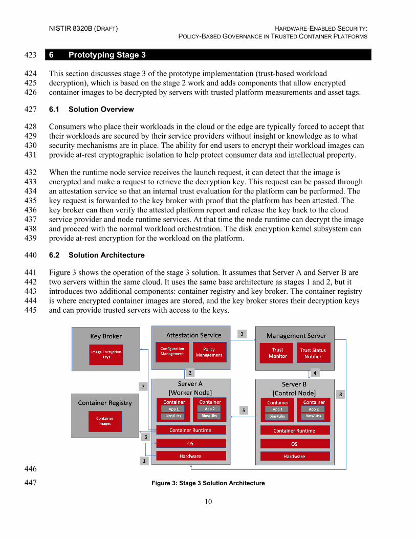
Figure 3 shows the operation of the stage 3 solution. It assumes that Server A and Server B are 441 two servers within the same cloud. It uses the same base architecture as stages 1 and 2, but it 442 introduces two additional components: container registry and key broker. The container registry 443 is where encrypted container images are stored, and the key broker stores their decryption keys 444 and can provide trusted servers with access to the keys. 445
446
Figure 3: Stage 3 Solution Architecture 447
NISTIR 8320B (DRAFT) HARDWARE-ENABLED SECURITY: POLICY-BASED GOVERNANCE IN TRUSTED CONTAINER PLATFORMS
11
There are eight generic steps performed in the operation of the stage 3 prototype, as outlined 448 below and reflected by the numbers in Figure 3: 449
1. Server A performs a measured launch, with the enhanced hardware-based security 450 features populating the measurements in the hardware module. 451
2. Server A sends a quote to the Attestation Service. The quote includes signed hashes of 452 various platform firmware and OS components. 453
3. The Trust Authority verifies the signature and hash values, and sends the attestation of 454 the platform’s integrity state to the Management Server. 455
4. The Management Server enforces workload policy requirements on Server B based on 456 user requirements. 457
5. Server B launches workloads that require trusted infrastructure only on server platforms 458 that have been attested to be trusted. 459
6. Server A pulls the encrypted workload image from the Container Registry so that it can 460 launch an instance of the workload. 461
7. The Key Broker releases the workload decryption key to Server A only if it has a trusted 462 attestation report, and Server A launches an instance of the workload. 463
8. Each server platform gets audited periodically based on its measurement values. 464

NISTIR 8320B (DRAFT) HARDWARE-ENABLED SECURITY: POLICY-BASED GOVERNANCE IN TRUSTED CONTAINER PLATFORMS
12
7 Prototyping Stage 4 465
This section discusses stage 4 of the prototype implementation (trust-based workload access to 466 information), which is based on the stage 3 work and adds components that create identities for 467 individual workloads so that they can be granted appropriate access to sensitivity information. 468
7.1 Solution Overview 469
The majority of workloads running in the cloud need some access to data sources or other 470 services. To do this, they must authenticate themselves using a password, API key, or certificate. 471 Today, this is typically done through secrets. Even though secrets are designed to be stored 472 securely (for example, encrypted at rest) by the orchestration, they can simply be mounted to an 473 arbitrary container and read by anyone who has access to the namespace, including cloud 474 administrators. Those knowing the secret can also access the sensitive data that needs to be 475 protected. The problem with the secrets is that once they are stored, they are also available to 476 administrators, cloud operators, or anyone else with access to the namespace, whether or not they 477 are authorized to access the data that the secrets protect. 478
Trust-based workload access to information protects sensitive data access by ensuring only 479 attested services with specific location-based restrictions can access the secrets. This is done 480 through the use of workload identity, which is composed of the trusted hardware identity data 481 that has been fully attested, including the data center location and region, and various runtime 482 measurements to identify the application. These measurements are securely signed by a service 483 running on each worker node, using a chain of trust created during the secure bootstrapping of 484 the environment, then continuously attested and validated. The bootstrapping of the environment 485 requires configuring a secret store that runs a root Certificate Authority (CA), and installing an 486 intermediate CA and token signing service on each worker node. Each worker node with the 487 token signing service uses its hardware root of trust to protect its individual private key. 488
7.2 Solution Architecture 489
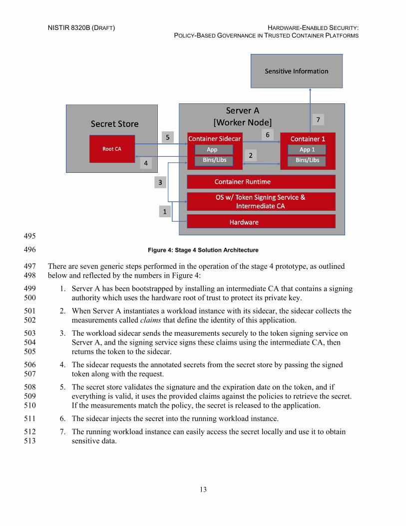
It is assumed that all the steps from stage 3 have been completed, and that a workload is 490 successfully deployed to a worker node before any steps of this stage begin. Figure 4 shows the 491 operation of the stage 4 solution, with the assumptions that the workload deployed is on top of a 492 trusted worker node and policies have been defined for the measurements of the application that 493 can access secrets. These measurements represent the identity of the application. 494
NISTIR 8320B (DRAFT) HARDWARE-ENABLED SECURITY: POLICY-BASED GOVERNANCE IN TRUSTED CONTAINER PLATFORMS
13
495
Figure 4: Stage 4 Solution Architecture 496
There are seven generic steps performed in the operation of the stage 4 prototype, as outlined 497 below and reflected by the numbers in Figure 4: 498
1. Server A has been bootstrapped by installing an intermediate CA that contains a signing 499 authority which uses the hardware root of trust to protect its private key. 500
2. When Server A instantiates a workload instance with its sidecar, the sidecar collects the 501 measurements called claims that define the identity of this application. 502
3. The workload sidecar sends the measurements securely to the token signing service on 503 Server A, and the signing service signs these claims using the intermediate CA, then 504 returns the token to the sidecar. 505
4. The sidecar requests the annotated secrets from the secret store by passing the signed 506 token along with the request. 507
5. The secret store validates the signature and the expiration date on the token, and if 508 everything is valid, it uses the provided claims against the policies to retrieve the secret. 509 If the measurements match the policy, the secret is released to the application. 510
6. The sidecar injects the secret into the running workload instance. 511 7. The running workload instance can easily access the secret locally and use it to obtain 512
sensitive data. 513

NISTIR 8320B (DRAFT) HARDWARE-ENABLED SECURITY: POLICY-BASED GOVERNANCE IN TRUSTED CONTAINER PLATFORMS
14
References 514
[1] Bartock M, Souppaya M, Wheeler J, Knoll T, Shetty U, Savino R, Inbaraj J, Righi S, Scarfone K (2021) Hardware-Enabled Security: Container Platform Security Prototype. (National Institute of Standards and Technology, Gaithersburg, MD), NIST Interagency or Internal Report (IR) 8320A. https://doi.org/10.6028/NIST.IR.8320A
[2] Bartock M, Souppaya M, Savino R, Knoll T, Shetty U, Cherfaoui M, Yeluri R, Malhotra A, Banks D, Jordan M, Pendarakis D, Rao JR, Romness P, Scarfone KA (2021) Hardware-Enabled Security: Enabling a Layered Approach to Platform Security for Cloud and Edge Computing Use Cases. (National Institute of Standards and Technology, Gaithersburg, MD), 2nd Draft NIST Interagency or Internal Report (IR) 8320. https://doi.org/10.6028/NIST.IR.8320-draft2
[3] Polydys ML, Wisseman S (2009) Software Assurance in Acquisition: Mitigating Risks to the Enterprise. https://apps.dtic.mil/dtic/tr/fulltext/u2/a495389.pdf
[4] Joint Task Force (2020) Security and Privacy Controls for Information Systems and Organizations. (National Institute of Standards and Technology, Gaithersburg, MD), NIST Special Publication (SP) 800-53, Rev. 5. Includes updates as of December 10, 2020. https://doi.org/10.6028/NIST.SP.800-53r5
[5] National Institute of Standards and Technology (2018), Framework for Improving Critical Infrastructure Cybersecurity, Version 1.1. (National Institute of Standards and Technology, Gaithersburg, MD). https://doi.org/10.6028/NIST.CSWP.04162018
NISTIR 8320B (DRAFT) HARDWARE-ENABLED SECURITY: POLICY-BASED GOVERNANCE IN TRUSTED CONTAINER PLATFORMS
15
Appendix A—Hardware Root of Trust Implementation 515
This appendix provides an overview of the high-level hardware architecture of the prototype 516 implementation, as well as details on how Intel platforms implement hardware modules and 517 enhanced hardware-based security functions. 518
A.1 High-Level Implementation Architecture 519
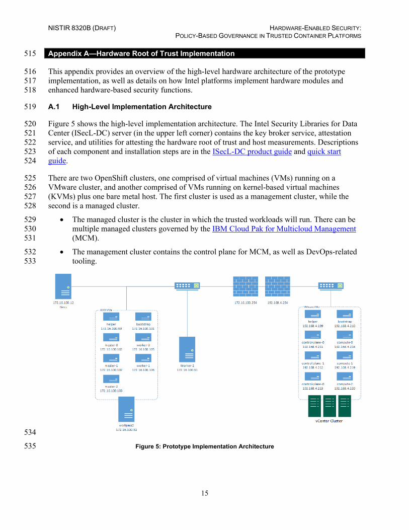
Figure 5 shows the high-level implementation architecture. The Intel Security Libraries for Data 520 Center (ISecL-DC) server (in the upper left corner) contains the key broker service, attestation 521 service, and utilities for attesting the hardware root of trust and host measurements. Descriptions 522 of each component and installation steps are in the ISecL-DC product guide and quick start 523 guide. 524
There are two OpenShift clusters, one comprised of virtual machines (VMs) running on a 525 VMware cluster, and another comprised of VMs running on kernel-based virtual machines 526 (KVMs) plus one bare metal host. The first cluster is used as a management cluster, while the 527 second is a managed cluster. 528
• The managed cluster is the cluster in which the trusted workloads will run. There can be 529 multiple managed clusters governed by the IBM Cloud Pak for Multicloud Management 530 (MCM). 531
• The management cluster contains the control plane for MCM, as well as DevOps-related 532 tooling. 533
534
Figure 5: Prototype Implementation Architecture 535

NISTIR 8320B (DRAFT) HARDWARE-ENABLED SECURITY: POLICY-BASED GOVERNANCE IN TRUSTED CONTAINER PLATFORMS
16
A.2 Hardware Root of Trust: Intel TXT and Trusted Platform Module (TPM) 536
Hardware-based root-of-trust, when coupled with an enabled BIOS, OS, and components, 537 constitutes the foundation for a more secure computing platform. This secure platform ensures 538 BIOS and OS integrity at boot from rootkits and other low-level attacks. It establishes the 539 trustworthiness of the server and host platforms. 540
There are three roots of trust in a trusted platform: root of trust for measurement (RTM), root of 541 trust for reporting (RTR), and root of trust for storage (RTS). They are the foundational elements 542 of a single platform. These are the system elements that must be trusted, because misbehavior in 543 these normally would not be detectable in the higher layers. In an Intel Trusted Execution 544 Technology (TXT) enabled platform, the RTM is the Intel microcode: the Core-RTM (CRTM). 545 An RTM is the first component to send integrity-relevant information (measurements) to the 546 RTS. Trust in this component is the basis for trust in all the other measurements. RTS contains 547 the component identities (measurements) and other sensitive information. A trusted platform 548 module (TPM) provides the RTS and RTR capabilities in a trusted computing platform. 549
Intel TXT is the RTM, and it is a mechanism to enable visibility, trust, and control in the cloud. 550 Intel TXT is a set of enhanced hardware components designed to protect sensitive information 551 from software-based attacks. Intel TXT features include capabilities in the microprocessor, 552 chipset, I/O subsystems, and other platform components. When coupled with an enabled OS and 553 enabled applications, these capabilities safeguard the confidentiality and integrity of data in the 554 face of increasingly hostile environments. 555
Intel TXT incorporates a number of secure processing innovations, including: 556
• Protected execution: Lets applications run in isolated environments so that no 557 unauthorized software on the platform can observe or tamper with the operational 558 information. Each of these isolated environments executes with the use of dedicated 559 resources managed by the platform. 560
• Sealed storage: Provides the ability to encrypt and store keys, data, and other sensitive 561 information within the hardware. This can only be decrypted by the same environment 562 that encrypted it. 563
• Attestation: Enables a system to provide assurance that the protected environment has 564 been correctly invoked and to take a measurement of the software running in the 565 protected space. This is achieved by the attestation process defined in the next subsection. 566 The information exchanged during this process is known as the attestation identity key 567 credential and is used to establish mutual trust between parties. 568
• Protected launch: Provides the controlled launch and registration of critical system 569 software components in a protected execution environment. 570
Intel Xeon® Platinum Scalable processor series and the previous generation Xeon Processor E3, 571 Xeon Processor E5, and Xeon Processor E7 series processors support Intel TXT. 572
Intel TXT works through the creation of a measured launch environment (MLE) enabling an 573 accurate comparison of all the critical elements of the launch environment against a known good 574

NISTIR 8320B (DRAFT) HARDWARE-ENABLED SECURITY: POLICY-BASED GOVERNANCE IN TRUSTED CONTAINER PLATFORMS
17
source. Intel TXT creates a cryptographically unique identifier for each approved launch-enabled 575 component and then provides a hardware-based enforcement mechanism to block the launch of 576 any code that does not match or, alternately, indicate when an expected trusted launch has not 577 happened through a process of secure remote attestation. In the latter case, when an attestation 578 indicates that one or more measured components in the MLE do not match expectations, 579 orchestration of workloads can be prevented on the suspect platform, even though the platform 580 itself still launches. This hardware-based solution provides the foundation on which IT 581 administrators can build trusted platform solutions to protect against aggressive software-based 582 attacks and to better control their virtualized or cloud environments. 583
A.3 Attestation: Intel Security Libraries (ISecL) 584
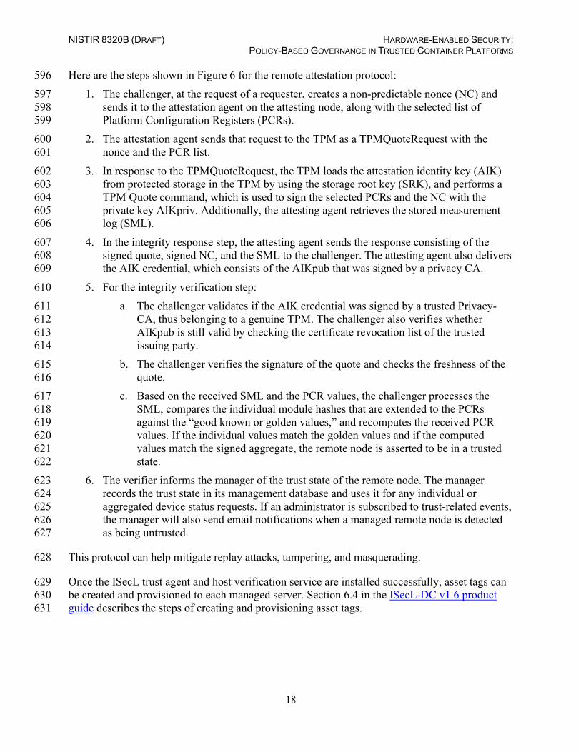
An attestation authority provides the definitive answers to these questions. Attestation provides 585 cryptographic proof of compliance, utilizing the root of trust concept to provide actionable 586 security controls by making the information from various roots of trust visible and usable by 587 other entities. Figure 6 illustrates the attestation protocol providing the means for conveying 588 measurements to the challenger. The endpoint attesting device must have a means of measuring 589 the BIOS firmware, low-level device drivers, and OS and other measured components, and 590 forwarding those measurements to the attestation authority. The attesting device must do this 591 while protecting the integrity, authenticity, nonrepudiation, and in some cases, confidentiality of 592 those measurements. 593
594
Figure 6: Remote Attestation Protocol 595
NISTIR 8320B (DRAFT) HARDWARE-ENABLED SECURITY: POLICY-BASED GOVERNANCE IN TRUSTED CONTAINER PLATFORMS
18
Here are the steps shown in Figure 6 for the remote attestation protocol: 596 1. The challenger, at the request of a requester, creates a non-predictable nonce (NC) and 597
sends it to the attestation agent on the attesting node, along with the selected list of 598 Platform Configuration Registers (PCRs). 599
2. The attestation agent sends that request to the TPM as a TPMQuoteRequest with the 600 nonce and the PCR list. 601
3. In response to the TPMQuoteRequest, the TPM loads the attestation identity key (AIK) 602 from protected storage in the TPM by using the storage root key (SRK), and performs a 603 TPM Quote command, which is used to sign the selected PCRs and the NC with the 604 private key AIKpriv. Additionally, the attesting agent retrieves the stored measurement 605 log (SML). 606
4. In the integrity response step, the attesting agent sends the response consisting of the 607 signed quote, signed NC, and the SML to the challenger. The attesting agent also delivers 608 the AIK credential, which consists of the AIKpub that was signed by a privacy CA. 609
5. For the integrity verification step: 610 a. The challenger validates if the AIK credential was signed by a trusted Privacy-611
CA, thus belonging to a genuine TPM. The challenger also verifies whether 612 AIKpub is still valid by checking the certificate revocation list of the trusted 613 issuing party. 614
b. The challenger verifies the signature of the quote and checks the freshness of the 615 quote. 616
c. Based on the received SML and the PCR values, the challenger processes the 617 SML, compares the individual module hashes that are extended to the PCRs 618 against the “good known or golden values,” and recomputes the received PCR 619 values. If the individual values match the golden values and if the computed 620 values match the signed aggregate, the remote node is asserted to be in a trusted 621 state. 622
6. The verifier informs the manager of the trust state of the remote node. The manager 623 records the trust state in its management database and uses it for any individual or 624 aggregated device status requests. If an administrator is subscribed to trust-related events, 625 the manager will also send email notifications when a managed remote node is detected 626 as being untrusted. 627
This protocol can help mitigate replay attacks, tampering, and masquerading. 628
Once the ISecL trust agent and host verification service are installed successfully, asset tags can 629 be created and provisioned to each managed server. Section 6.4 in the ISecL-DC v1.6 product 630 guide describes the steps of creating and provisioning asset tags. 631

NISTIR 8320B (DRAFT) HARDWARE-ENABLED SECURITY: POLICY-BASED GOVERNANCE IN TRUSTED CONTAINER PLATFORMS
19
Appendix B—Workload Orchestration Implementation: OpenShift 632
This section contains supplementary information describing all the components and steps 633 required to set up the prototype implementation for OpenShift. 634
B.1 Prototype Architecture 635
Kubernetes has become a popular source for building large web-scale technologies that enable 636 the enterprise to take advantage of innovations like analytics, artificial intelligence, machine 637 learning, and cloud services. Supporting advanced technologies and building cloud-native 638 applications requires enterprise-grade platforms such as Red Hat OpenShift. This section 639 describes the provisioning and configuration of OpenShift clusters. Figure 7 shows how the 640 nodes from Figure 5 (in Appendix A) in the architecture are logically implemented into two 641 OpenShift clusters and the Remote Attestation Server. 642
643
Figure 7: Prototype Architecture 644
To implement use cases, OpenShift is deployed in two separate clusters: Management Cluster 645 based on VMWare, and Managed Cluster based on KVM infrastructure. Each cluster has three 646 control-plane and three worker nodes, and a VM with load balancer and DNS to simulate the 647 trusted container workload environment. MCM components are deployed on both OpenShift 648 clusters. The Managed Cluster has an MCM Hub component, which aggregates information from 649 multiple clusters using an asynchronous work request model. The hub cluster (Management 650 Cluster) maintains the status of clusters and applications, and provides a set of APIs for the 651 various functions to support as a central controller. The Managed Cluster has an MCM managed-652
NISTIR 8320B (DRAFT) HARDWARE-ENABLED SECURITY: POLICY-BASED GOVERNANCE IN TRUSTED CONTAINER PLATFORMS
20
cluster component used to define the cluster, with the MCM Klusterlet and other resources 653 configured to initiate a connection to the hub cluster. The Managed Cluster receives work 654 requests and applies them, then returns the results. 655
B.2 OpenShift Installation and Configuration 656
Managing the OpenShift platform in multiple places comes with challenges like complexity, 657 governance, and cost. For example, how do you gain visibility into all the clusters to see where 658 the application’s components are running? How do you know which systems are failing? How 659 can you monitor usage across the clouds and clusters? How do you govern the configuration and 660 changes to this environment? IBM Cloud Pak for Multicloud Management/Red Hat Advanced 661 Cluster Management for Kubernetes supports the use cases. It is based on the Kubernetes 662 community direction and includes advanced functions important to running enterprise-grade 663 environments. 664
The Policies repository, which is part of the Manager hub component, resides on the 665 Management Cluster. The repository comes with default compliance and policies templates, but 666 our use cases developed new policies that reflected our environment to integrate with the Intel 667 attestation hub. The repository holds the policy defined for the Managed Cluster, and the policy 668 document is applied by using placement bind. 669
B.2.1 VMware-Based Management Cluster (Cluster A) 670
Hardware Requirement: For deploying OpenShift Container Platform (OCP) 4.3 on VMware, 671 the minimum recommendation is to provision one ESXi server and one Centos/Red Hat VM on 672 the same virtual local area network (VLAN) in the local datacenter. For this deployment, the 673 setup was an ESXi bare-metal server with 48 CPUs, 256 GB RAM, and 2 TB storage. The 674 Centos/Red Hat VM is only required for a few hours and can be de-provisioned after the install 675 is complete. 676
Networking: The IP addresses used in this process and the configuration files came from our 677 NCCoE environment. They are used here for illustration purposes only. Besides setting up your 678 ESXi and vCenter server, you need to have a minimum of 16 IP addresses to assign to the VMs. 679 Each VM node takes one IP address. The recommended minimum of 16 IP addresses is 680 determined by: 1 helper node + 1 boot node + 3 control-plane nodes + 3 worker nodes = 8 nodes. 681 The extra IP addresses are available in case additional worker nodes are required in the future. 682 This installation provisioned the vCenter on the same IP subnet, so a total of 9 IP addresses were 683 used. 684
VMware OCP VM Requirements: Table 1 lists the VMs that are instantiated on the VMware 685 server, along with their virtual hardware requirements and the roles they serve in the cluster. 686

NISTIR 8320B (DRAFT) HARDWARE-ENABLED SECURITY: POLICY-BASED GOVERNANCE IN TRUSTED CONTAINER PLATFORMS
21
Table 1: VMs Instantiated on the VMware-Based Management Cluster 687
Node Name vCPU Mem (GB)
HDD (GB)
Role
Helper Node 4 16 150 LB/DNS/Proxy/DHCP/OCP Installer Bootstrap-0 4 16 150 Bootstrap OCP Control-plane-0 4 16 150 Controller OCP Control-plane-1 4 16 150 Controller OCP Control-plane-2 4 16 150 Controller OCP compute-0 4 16 150 Compute OCP compute-1 4 16 150 Compute OCP compute-2 4 16 150 Compute OCP
OCP VMware Deployment Playbooks: To deploy OCP 4.3 on VMware, download the 688 following Git repository: https://github.com/fctoibm/ocpvmware4.3 and follow the steps to run 689 the playbooks. Make sure to change the vars.yaml and host.yaml files to match the 690 networking information for your environment. 691
B.2.2 KVM-Based Managed Cluster (Cluster B) 692
The second OCP cluster is the managed cluster. It contains an MCM Klusterlet, which ensures 693 that each managed cluster adheres to the policy in place. 694
Hardware Requirement: For this deployment, the lab setup was on a CentOS bare-metal server 695 with 48 CPUs, 256 GB RAM, and 1 TB storage. KVM will be used to create and manage virtual 696 machines. The KVM command line tool is virt-install and the GUI tool is virt-manager. 697 To use the KVM GUI tool, install Gnome desktop and VNC on the CentOS bare-metal server. 698 All of the VMs for this managed cluster are deployed on this single KVM host, which has 699 hostname wolfpass2 in the table and image in Figure 5 (in Appendix A). 700
Networking: The IP addresses used in this process and the configuration files came from our 701 NCCoE environment. They are used here for illustration purposes only. When you install OCP in 702 the KVM host environment, you will also need a minimum of 16 portable IP addresses. Each 703 VM node takes up one IP address. The recommended minimum of 16 portable IP addresses is 704 determined by: 1 helper node + 1 boot node + 3 control-plane nodes + 3 worker nodes = 8 nodes. 705 The extra IP addresses are available for additional worker nodes required in the future. You 706 should plan your IP address space accordingly. 707
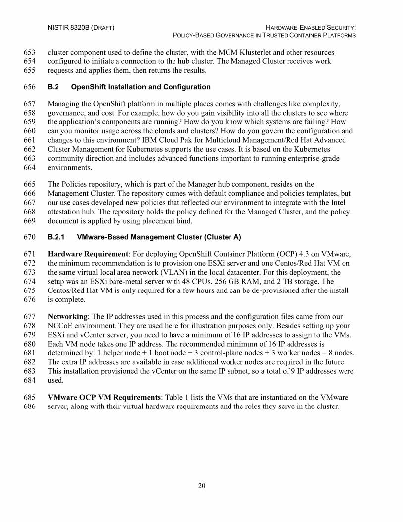
KVM OCP VM Requirements: Table 2 lists the VMs that are instantiated on the KVM server, 708 along with their virtual hardware requirements and the roles they serve in the managed cluster. 709
NISTIR 8320B (DRAFT) HARDWARE-ENABLED SECURITY: POLICY-BASED GOVERNANCE IN TRUSTED CONTAINER PLATFORMS
22
Table 2: VMs Instantiated on the KVM-Based Managed Cluster 710
Node Name vCPU Mem (GB)
HDD (GB)
Role
Helper Node 4 16 150 DNS/Proxy/DHCP/OCP Installer Bootstrap 4 16 150 Bootstrap OCP Master0 4 16 150 Controller OCP Master1 4 16 150 Controller OCP Master2 4 16 150 Controller OCP Worker0 4 16 150 Compute OCP Worker1 4 16 150 Compute OCP
Note: The OpenShift cluster requires three worker nodes; however, since this deployment uses 711 an additional physical sever for the third worker node, only two worker node VMs are deployed. 712
OCP KVM Deployment Playbooks: To deploy OCP 4.3 on KVM, download the following Git 713 repository: https://github.com/fctoibm/ocpkvm4.3 and follow the steps to run the playbooks. 714 Make sure to change the vars.yaml and host.yaml files to match the networking information 715 of your environment. 716
The OCP KVM deployment playbook creates all of the worker nodes as virtual machines. In 717 order to create policies bases on hardware roots of trust, a physical server with the Intel TXT and 718 TPM capabilities must be added as an additional worker node to the cluster. This server needs to 719 have the corresponding Red Hat Enterprise Linux (RHEL) OS installed, as well as the Intel Trust 720 Agent as described in Appendix A.2. For the physical server, the OpenShift documentation 721 details how to add an RHEL compute node to an existing cluster. 722
B.2.3 Installing MCM Pak 1.3 (MCM HUB - VMware) 723
To install MCM Pak 1.3 on OCP 4.3, the setup assumes OCP 4.3 is already installed and 724 administrator-level access is available to deploy the MCM Pak. The guide assumes OCP 4.3 was 725 installed using the same GitHub repository and the same vars.yaml file. 726
Deploying MCM Pak: The installation Git repository supports two options, VMware or KVM 727 install, and both will deploy a VM guest if required. The VM guest called PakHelper node will 728 act as a client to install MCM Pak. There is no reason to deploy a VM guest client if you already 729 have a VM guest Centos 7 OS available in the same network. If the Centos 7 VM is already in 730 place, please skip options 1 and 2, but if there is no VM guest available, please execute both 731 options 1 or 2 and 3 from the following Git repository: https://github.com/fctoibm/mcmpak1.3 732 and follow the steps to run the playbooks. 733
Adding KVM OCP as Managed Cluster in MCM: Once the MCM Pak has been deployed, the 734 KVM OCP cluster can be imported into, and managed by, the IBM MCM. To do so, browse to 735 the web user interface (UI) of MCM and navigate to the Clusters management page. As shown in 736 Figure 8, there is an option to import an existing cluster. To import the existing KVM OCP 737 cluster, perform the steps in this IBM knowledge center article. 738

NISTIR 8320B (DRAFT) HARDWARE-ENABLED SECURITY: POLICY-BASED GOVERNANCE IN TRUSTED CONTAINER PLATFORMS
23
739
Figure 8: MCM Console to Import a Cluster 740
Creating Policies for Managed Cluster: Once the KVM OCP cluster has been successfully 741 imported, specific polices that govern workload orchestration can be created and applied. 742 Policies are created in the MCM Hub, and these policies are propagated to each managed cluster, 743 where they are enforced. Two policies were put in place for our prototype implementation: 744
1. The “Trusted Node Policy” ensures that all nodes in the cluster are trusted and attested. In 745 the inform mode, the policy logs whenever the trust status of a node has been violated. In 746 the enforce mode, the policy drains and removes the node from the cluster. 747
2. The “Trusted Container Policy” ensures that all workloads run within a namespace are 748 using a set of images from a particular registry path. The infrastructure is set up so only 749 encrypted container images are in that path. This makes it so only encrypted images are 750 run within the namespace. 751
Figure 9 shows the two policies in the web user interface that have been created for the managed 752 clusters. 753

NISTIR 8320B (DRAFT) HARDWARE-ENABLED SECURITY: POLICY-BASED GOVERNANCE IN TRUSTED CONTAINER PLATFORMS
24
754
Figure 9: Managed Cluster Policies 755
In addition to these two policies, there is a Tekton task set up as part of the OpenShift pipeline 756 that does a set of checks and encrypts the image. This secure pipeline does building, 757 vulnerability scanning, and encryption. More details on this pipeline are provided in Appendix C. 758
NISTIR 8320B (DRAFT) HARDWARE-ENABLED SECURITY: POLICY-BASED GOVERNANCE IN TRUSTED CONTAINER PLATFORMS
25
Appendix C— Workload Encryption Implementation 759
This section contains supplementary information describing all the components and steps 760 required to set up the prototype implementation for container workload encryption. 761
C.1 Prototype Architecture 762
Refer to Figure 7 from Appendix B for the relevant architecture diagram. 763
C.2 Workload Encryption Configuration 764
Various parts of the container ecosystem allow the enablement of workload encryption via 765 container image encryption. The technology is based on the Open Container Initiative (OCI) 766 container image specification. The components that support the use of this are: 767
• Build: The Skopeo tool is used to encrypt the container images and push them to the 768 registry. 769
• Runtime: The Cri-o container runtime came as part of OpenShift and was configured to 770 decrypt the images. It is the default runtime of OpenShift 4.3 worker nodes and supports 771 decrypting OCI container images. 772
• Registry: The Docker Distribution registry is used to push, pull, and store the encrypted 773 images. The version used was v2.7.1. 774
These are the core components of workload encryption. Several integrations were required with 775 the ISecL Attestation Hub’s APIs to showcase the workload and image encryption with hardware 776 attestation. A custom container encryption metadata scheme was defined to work with the ISecL 777 key broker. The reference implementation code and the document are located at 778 https://github.com/lumjjb/seclkeywrap. 779
Key integration points are: 780
• A custom container encryption metadata scheme was defined to work with the ISecL key 781 broker. 782
• The core components CRI-0 and Skopeo were patched to enable the use of the custom 783 ISecL protocol. The patches are available at https://github.com/lumjjb/cri-784 o/tree/sample_integration and https://github.com/lumjjb/skopeo/tree/sample_integration, 785 respectively. 786
As part of the DevSecOps cycle, it was integrated with the development flow with the Tekton 787 pipeline to perform builds, security checks, and image encryption. The pipeline workflow can be 788 reached through the OpenShift dashboard by toggling into the Developer role and selecting the 789 “Pipelines” menu, as shown in Figure 10. The definitions of the Tekton objects are available 790 here: https://gist.github.com/lumjjb/22191008f849f240851aec8a1ee0304d 791

NISTIR 8320B (DRAFT) HARDWARE-ENABLED SECURITY: POLICY-BASED GOVERNANCE IN TRUSTED CONTAINER PLATFORMS
26
792
Figure 10: Creating Pipeline for Image Decryption 793

NISTIR 8320B (DRAFT) HARDWARE-ENABLED SECURITY: POLICY-BASED GOVERNANCE IN TRUSTED CONTAINER PLATFORMS
27
Appendix D—Trusted Service Identity (TSI) 794
This section contains supplementary information describing all the required components and 795 steps required to set up the prototype implementation for the Trusted Service Identity (TSI). 796
D.1 TSI Overview 797
TSI protects sensitive data access by ensuring only attested services with specific location-based 798 restrictions can obtain credentials. This is done through the use of workload identity, composed 799 of the trusted hardware identity data that has been fully attested by Intel TXT, including the data 800 center location and region, and various runtime measurements like the image and cluster name, 801 unique pod IDs, and namespace to identify the application. These measurements are securely 802 signed by a service running on every hosting node, using a chain of trust created during the 803 secure bootstrapping of the environment, then continuously attested and validated. 804
Every container that requires a secret for accessing sensitive data gets assigned a short-lived 805 measured identity, in the form of a JSON Web Token (JWT) token, that is signed with the root of 806 trust by the attested process. This measured identity is a form of an ephemeral digital biometric 807 with a short time to live. 808
In this implementation, there is a Kubernetes cluster running on OpenShift, extended with TSI, 809 where each node has an intermediate CA, signed by the root CA during the secure bootstrapping 810 of the cluster. 811
During this bootstrapping, the installation process obtains an attestation report (Security 812 Assertion Markup Language [SAML]) from the Attestation Server for every worker node. This 813 report is checked to verify if all the components are trusted (OS, platform, and software), and the 814 bootstrapping process retrieves worker identity fields from the asset tag of this report. Each 815 worker node also has a JWT Signing Service (JSS) that contains a signing authority that uses the 816 hardware TPM to protect its individual private key. 817
The root CA is securely stored in a vault, which is extended with the TSI Authentication Vault 818 plugin. 819
D.2 TSI Installation and Configuration 820
TSI requires an attestation process to accurately define the identity of the worker nodes hosting 821 the application containers. In this implementation, TSI relies on the ISecL server that has been 822 deployed to provide the identity of the worker nodes. Steps detailing the integration of TSI with 823 ISecL can be found here: https://github.com/IBM/trusted-service-identity/blob/intel-824 asset/README.md#attestation. 825
This process requires two independent phases: 826
• Asset Registration with Intel Verification Server – The trusted bootstrapping process 827 responsible for installing the environment must properly set the identity attributes of 828 every worker node. These identity values in the form of asset tags are securely stored in 829 their corresponding TPMs on hosts. As a result, they are included in the SAML 830
NISTIR 8320B (DRAFT) HARDWARE-ENABLED SECURITY: POLICY-BASED GOVERNANCE IN TRUSTED CONTAINER PLATFORMS
28
attestation report that also includes all the attestation results (OS, platform, software 831 trusted). This process was performed in the steps outlined in Appendix A. 832
• TSI Deployment with Attestation – The implementation outlined in this document 833 allows for the use of the Intel Attestation Server to obtain the identity of the worker 834 nodes. There are several changes required to configure the TSI installation to support 835 Intel Attestation Server. Additionally, a hardware TPM device is shared between the Intel 836 Trust Agent and the TSI JWT Signing Service, and it requires the use of TPM proxy. For 837 details outlining the suggested configuration changes, visit 838 https://github.com/IBM/trusted-service-identity/blob/intel-asset/README.md - 839 attestation. 840
As a result of these changes, TSI will be installed in the cluster, using an attestation report from 841 the Intel Attestation Service to provide the identities of the workers and to keep the attestation 842 going. 843
Before secrets can be injected into the application container, first they need to be created in the 844 Secret Store (Vault). Follow these steps for injecting secrets to the Vault: 845 https://github.com/IBM/trusted-service-846 identity/blob/master/examples/vault/README.md#secrets 847
Once the application is started, secrets will be injected based on the application identity, 848 including the workload environment and location. As a result, the secret will be delivered to the 849 container runtime memory without ever being stored anywhere in Kubernetes—but from the 850 point of view of the application, no additional changes were needed. 851
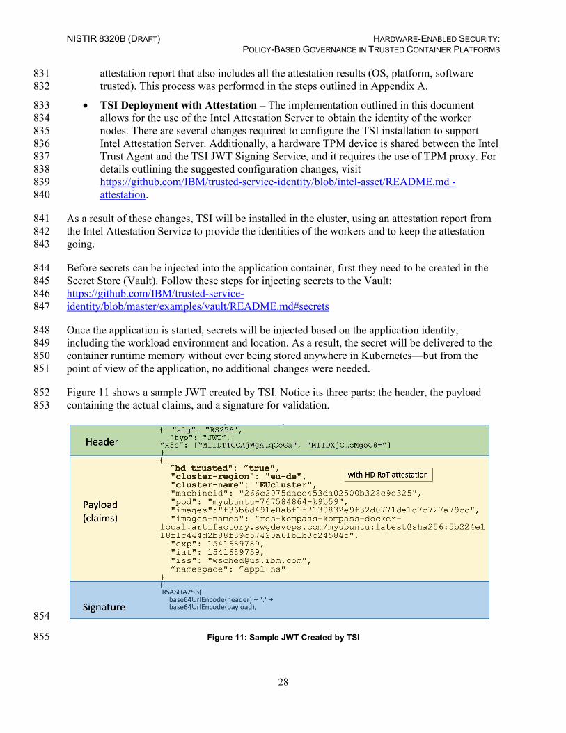
Figure 11 shows a sample JWT created by TSI. Notice its three parts: the header, the payload 852 containing the actual claims, and a signature for validation. 853
854
Figure 11: Sample JWT Created by TSI 855

NISTIR 8320B (DRAFT) HARDWARE-ENABLED SECURITY: POLICY-BASED GOVERNANCE IN TRUSTED CONTAINER PLATFORMS
29
The claims included here represent the measured identity of the application. They contain some 856 static values like cluster-region (e.g., Germany, eu-de), cluster-name, individual 857 machineid which is a unique worker node ID, and several runtime measurements like a 858 namespace, unique pod ID, and the list of images making up the pod. These images include the 859 image signature, so you can validate the image and guarantee that the application is running the 860 code that you want to be running and it was not tampered with. The hd-trusted value 861 determines whether all the attested elements are trusted. 862
Values for cluster-name, cluster-region, and hd-trusted are essential for defining the 863 identity of the compute resources, and they are read from Intel’s Attestation Server. There is also 864 a token expiration timestamp, typically set to one minute, to make these tokens ephemeral and 865 short-lived, protecting the security from leaking. These are the runtime measurements that 866 represent the identity of the application, signed with the root of trust, and used for evaluation 867 against policies controlling the secrets. 868
The secrets stored in the Vault are protected by policies. Policies are composed of the policy-869 type and the attributes, the same that are used for building claims, and they represent the path to 870 the secret. If the claims provided in the request matches the policy attribute path, the secret will 871 be released to the application. 872
NISTIR 8320B (DRAFT) HARDWARE-ENABLED SECURITY: POLICY-BASED GOVERNANCE IN TRUSTED CONTAINER PLATFORMS
30
Appendix E—Supporting NIST SP 800-53 Security Controls and Publications 873
The major controls in the NIST SP 800-53 Revision 5, Security and Privacy Controls for 874 Information Systems and Organizations [4] control catalog that affect the container platform 875 security prototype implementation are: 876
• AU-2, Event Logging 877
• CA-2, Control Assessments 878
• CA-7, Continuous Monitoring 879
• CM-2, Baseline Configuration 880
• CM-3, Configuration Change Control 881
• CM-8, System Component Inventory 882
• IR-4, Incident Handling 883
• SA-9, External System Services 884
• SC-1, Policy and Procedures [for System and Communications Protection Family] 885
• SC-7, Boundary Protection 886
• SC-29, Heterogeneity 887
• SC-32, System Partitioning 888
• SC-36, Distributed Processing and Storage 889
• SI-3, Malicious Code Protection 890
• SI-4, System Monitoring 891
• SI-6, Security and Privacy Function Verification 892
• SI-7, Software, Firmware, and Information Integrity 893
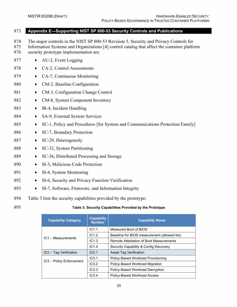
Table 3 lists the security capabilities provided by the prototype: 894
Table 3: Security Capabilities Provided by the Prototype 895
Capability Category Capability Number Capability Name
IC1 – Measurements
IC1.1 Measured Boot of BIOS IC1.2 Baseline for BIOS measurement (allowed list) IC1.3 Remote Attestation of Boot Measurements IC1.4 Security Capability & Config Discovery
IC2 – Tag Verification IC2.1 Asset Tag Verification
IC3 – Policy Enforcement IC3.1 Policy-Based Workload Provisioning IC3.2 Policy-Based Workload Migration
IC3.3 Policy-Based Workload Decryption IC3.4 Policy-Based Workload Access
NISTIR 8320B (DRAFT) HARDWARE-ENABLED SECURITY: POLICY-BASED GOVERNANCE IN TRUSTED CONTAINER PLATFORMS
31
Capability Category Capability Number Capability Name
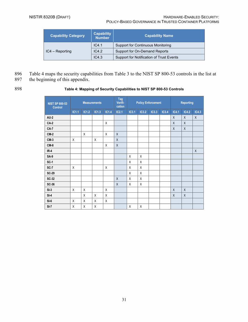
IC4 – Reporting IC4.1 Support for Continuous Monitoring IC4.2 Support for On-Demand Reports IC4.3 Support for Notification of Trust Events
Table 4 maps the security capabilities from Table 3 to the NIST SP 800-53 controls in the list at 896 the beginning of this appendix. 897
Table 4: Mapping of Security Capabilities to NIST SP 800-53 Controls 898
NIST SP 800-53 Control
Measurements Tag
Verifi-cation
Policy Enforcement Reporting
IC1.1 IC1.2 IC1.3 IC1.4 IC2.1 IC3.1 IC3.2 IC3.3 IC3.4 IC4.1 IC4.2 IC4.3 AU-2 X X X CA-2 X X X CA-7 X X CM-2 X X X CM-3 X X X CM-8 X X IR-4 X SA-9 X X SC-1 X X SC-7 X X X X SC-29 X X SC-32 X X X SC-36 X X X SI-3 X X X X X SI-4 X X X X X SI-6 X X X X SI-7 X X X X X

NISTIR 8320B (DRAFT) HARDWARE-ENABLED SECURITY: POLICY-BASED GOVERNANCE IN TRUSTED CONTAINER PLATFORMS
32
Appendix F—Cybersecurity Framework Subcategory Mappings 899
This appendix maps the major security features of the trusted geolocation prototype 900 implementation to the following subcategories from the Cybersecurity Framework [5]: 901
• ID.GV-1: Organizational information security policy is established 902
• ID.GV-3: Legal and regulatory requirements regarding cybersecurity, including privacy 903 and civil liberties obligations, are understood and managed 904
• PR.DS-6: Integrity checking mechanisms are used to verify software, firmware, and 905 information integrity 906
• PR.IP-5: Policy and regulations regarding the physical operating environment for 907 organizational assets are met 908
909
NISTIR 8320B (DRAFT) HARDWARE-ENABLED SECURITY: POLICY-BASED GOVERNANCE IN TRUSTED CONTAINER PLATFORMS
33
Appendix G—Acronyms and Other Abbreviations 910
Selected acronyms and abbreviations used in the report are defined below. 911
AIK Attestation Identity Key API Application Programming Interface BIOS Basic Input/Output System CA Certificate Authority CPU Central Processing Unit CRTM Core Root of Trust for Measurement DHCP Dynamic Host Configuration Protocol DNS Domain Name System FOIA Freedom of Information Act GB Gigabyte HD Hard Drive HDD Hard Disk Drive IaaS Infrastructure as a Service Intel TXT Intel Trusted Execution Technology I/O Input/Output IP Internet Protocol IR Interagency or Internal Report ISecL Intel Security Libraries ISecL-DC Intel Security Libraries for Data Center IT Information Technology ITL Information Technology Laboratory JSON JavaScript Object Notation JSS JWT Signing Service JWT JSON Web Token KVM Kernel-Based Virtual Machine MCM Multicloud Management MLE Measured Launch Environment NC Nonce NIST National Institute of Standards and Technology OCI Open Container Initiative OCP OpenShift Container Platform OS Operating System PCR Platform Configuration Register RAM Random Access Memory RHEL Red Hat Enterprise Linux RTM Root of Trust for Measurement RTR Root of Trust for Reporting RTS Root of Trust for Storage SAML Security Assertion Markup Language SML Stored Measurement Log SP Special Publication SRK Storage Root Key TB Terabyte
NISTIR 8320B (DRAFT) HARDWARE-ENABLED SECURITY: POLICY-BASED GOVERNANCE IN TRUSTED CONTAINER PLATFORMS
34
TPM Trusted Platform Module TSI Trusted Service Identity VLAN Virtual Local Area Network VM Virtual Machine
912