Embed Size (px)
Citation preview

170106 C67 Hwy 21 Slope Options Report_Draft.docx A05115B02
Klohn Crippen Berger LTD. • 500 - 2618 Hopewell Place NE • Calgary AB T1Y 7J7 • CANADA
403.274.3424 t • 403.274.5349 f www.klohn.com
January 6, 2017
Alberta Transportation 4th Floor, Provincial Building 4920 - 51 Street Red Deer, Alberta T4N 6K8 Tony, Penney, P.Eng. Construction Engineer, Project Administrator - Central Region GRMP Dear Mr. Penney: Site C67 – H21:14, km 12.8 Slope Failure Rehabilitation Options Assessment Report Draft Klohn Crippen Berger Ltd (KCB) is pleased to submit our draft report entitled “Site C67 – H21:14, km 12.8 Slope Failure Rehabilitation, Options Assessment Report”. This is a draft report only and we solicit your review and comments within two weeks of the submission. Upon issue of the final version of this report, we request that all draft reports should be destroyed or returned to KCB. This draft report should not be relied on as a final document for design and/or construction purposes. We appreciate the opportunity to continue providing our services to Alberta Transportation. Please do not hesitate to call the undersigned at 403.730.6818 should you require further information. Yours truly,
KLOHN CRIPPEN BERGER LTD. Peter Roy, P.Eng. Civil Engineer
PR:pr

Alberta Transportation Site C67 – H21:14, km 12.8 Slope Failure Rehabilitation
Options Assessment Report Draft
TABLE OF CONTENTS
170106 C67 Hwy 21 Slope Options Report_Draft.docx
Page i
A05115B02 January 2017
1 INTRODUCTION ........................................................................................................................ 1
1.1 Scope and Objectives ................................................................................................ 1
1.2 Site Description ......................................................................................................... 1
1.2.1 Site A .......................................................................................................... 2
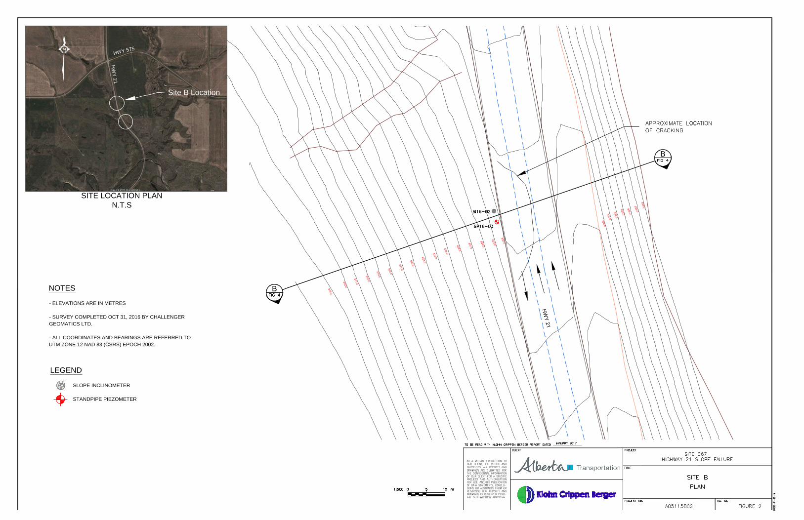
1.2.2 Site B .......................................................................................................... 2
2 GEOTECHNICAL INVESTIGATIONS ............................................................................................ 3
2.1 February 2016 Drilling Investigation ........................................................................ 3
2.2 November 2016 Drilling Investigation ...................................................................... 3
2.3 Instrumentation ........................................................................................................ 4
2.3.1 Slope Inclinometers ................................................................................... 4
2.3.2 Standpipe Piezometers .............................................................................. 4
2.3.3 Instrumentation Data ................................................................................ 4
2.4 Laboratory Testing .................................................................................................... 5
3 SUBSURFACE CONDITIONS ...................................................................................................... 6
3.1 Regional Geology Setting .......................................................................................... 6
3.2 2016 Geotechnical Site Characterization ................................................................. 6
3.2.1 Embankment Fill ........................................................................................ 6
3.2.2 Clay Till ....................................................................................................... 6
3.2.3 Silt .............................................................................................................. 7
4 REHABILITATION OPTIONS ...................................................................................................... 8
4.1 General ..................................................................................................................... 8
4.2 Design Basis Memorandum ...................................................................................... 8
4.3 Rehabilitation Options Discussion ............................................................................ 9
4.4 Rehabilitation Options Cost Estimates ................................................................... 10
5 SUMMARY .............................................................................................................................. 13
6 CLOSING ................................................................................................................................. 14
REFERENCES ....................................................................................................................................... 16

Alberta Transportation Site C67 – H21:14, km 12.8 Slope Failure Rehabilitation
Options Assessment Report Draft
TABLE OF CONTENTS (continued)
170106 C67 Hwy 21 Slope Options Report_Draft.docx
Page ii
A05115B02 January 2017
List of Tables
Table 2.1 Summary of 2016 Investigations ...................................................................................... 3
Table 2.2 Standpipe Installation Details ........................................................................................... 4
Table 4.1 Engineering Options Summary ......................................................................................... 9
Table 4.2 Option 1 (Site A) – Excavate and Replace Slide Area Cost Estimate .............................. 10
Table 4.3 Option 2 (Site A)– Pile Wall............................................................................................. 11
Table 4.4 Option 1 (Site B) – Excavate and Replace Slide Area Cost Estimate .............................. 11
Table 4.5 Option 2 (Site B) – Pile Wall ............................................................................................ 12
List of Figures
Figure 1 Site A – Plan Figure 2 Site B – Plan Figure 3 Site A – Section Figure 4 Site B – Section Figure 5 Option 1 Repair – Plan Figure 6 Option 1 Repair – Section 1 Figure 7 Option 1 Repair – Section 2 Figure 8 Option 2 Repair – Plan Figure 9 Option 2 Repair – Section
List of Appendices
Appendix I Site Inspection Reports
Appendix II 2016 Borehole Logs
Appendix III Slope Inclinometer Plots
Appendix IV Design Basis Memorandum

Alberta Transportation Site C67 – H21:14, km 12.8 Slope Failure Rehabilitation
Options Assessment Report Draft
170106 C67 Hwy 21 Slope Options Report_Draft.docx
Page 1
A05115B02 January 2017
1 INTRODUCTION
1.1 Scope and Objectives
Klohn Crippen Berger (KCB) has been contacted by Alberta Transportation (AT) to undertake the Preliminary Design of a slope failure repair at the C67 site. This site consists of two slope failure areas (Site A and Site B) which are approximately 400 m apart. The two sites are shown on Figure 1 and Figure 2, respectively. The focus of the assessment is to assess the slopes and to identify remedial measures to stabilize and prevent the slopes from further deterioration.
A record of the preliminary assessment and design basis for the design of repair for the subject site is presented in this report.
1.2 Site Description
AT Central Region Geohazard Risk Monitoring Plan (GRMP) site C67 is located on Hwy 21:14 km 12.8, approximately 1 km south of the junction with Hwy 575 and approximately 700 m north of Kneehill Creek, near Carbon, Alberta. The site is located upslope of an unnamed ephemeral tributary creek to Kneehill Creek. An ephemeral creek bed is located at the toe of the embankment slope. The highway was likely constructed as a side-hill embankment fill slope using material cut from the existing slope. The highway at this location includes two northbound lanes and one southbound lane. The Central Region GRMP Inspection Report completed in June 2016 is attached in Appendix I.
The legal description of the site is 12-19-029-23 W4. The 2015 Annual Average Daily Traffic (AADT) for Hwy 21 at this site was 1770 (both directions) and is regularly used by heavily loaded vehicles. There are two slope failure areas (Site A and Site B) which are described below.
The geohazard at this site consists of two embankment slope failures that are causing settlement of the highway surface. These embankment failures were likely caused by periods of heavy rainfall and the potential for buried springs in the slopes that are more active during periods of wet weather. During the summer of 2015, the Central Region of Alberta experienced greater than average amounts of precipitation. Weather stations at Wimbourne ACGM (approx. 45 km NE) and Three Hills (approx. 22 km N) show that between August 15 and 16, 2015, approximately 45 mm of precipitation was recorded in the area, and for the month of August 2015 the area received more than twice the monthly average precipitation. The slide at Site A accelerated in the summer of 2015 due to high
precipitation levels causing the pavement to settle by a maximum amount of about 75 mm at the centreline of the highway. The slide at Site A accelerated again in the summer of 2016 when the area received several heavy rainfall events with up to 42 mm of precipitation in 48 hours. The areas of distress are considered to be slow moving (creep movement) and likely represent transitional slides below the highway.
An asphalt overlay is planned for the site in May 2017. The slope remediation must be complete by this date to allow for this work to be completed as scheduled.

Alberta Transportation Site C67 – H21:14, km 12.8 Slope Failure Rehabilitation
Options Assessment Report Draft
170106 C67 Hwy 21 Slope Options Report_Draft.docx
Page 2
A05115B02 January 2017
1.2.1 Site A
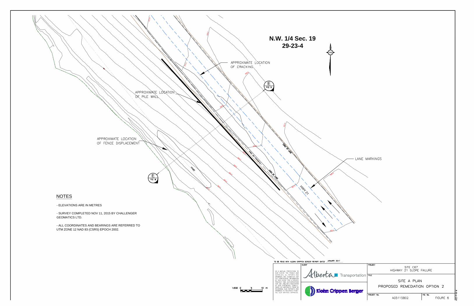
Site A, as shown on Figure 1, is located approximately a quarter of the way up the east valley slope.
The pavement distress and associated slide movement on the highway is occurring over an 80 m long section of pavement with distress and cracking observed at the crest of an approximately 9 m high embankment slope. The cracks extend from the southbound lane into the northbound passing lane, approximately half way across the highway (about 7 m, in the east direction, from the edge of the pavement) in a generally semi-circular pattern over the 80 m length.
The embankment slope below the distressed area is about 4H:1V and is covered in grass. A toe bulge was not observed, but the barbed wire fence is displaced approximately 1 m downslope in the slide area.
Slide movements accelerated in 2015 and again in 2016 due to the high rainfall levels in the region (see Section 1.2). Springs are likely also present in the area but were not observed during the site inspection or site investigation (see Section 2). It is unknown if any springs were buried during the original highway construction.
Based on the risk level criteria provided by Alberta Transportation relating to safety, a risk rating of 55 was assigned to this site. This is based on a probability factor of 11 for an active slide zone, and a consequence factor of 5 due to the impact to vehicles travelling on the highway.
1.2.2 Site B
Site B, as shown on Figure 2, is located approximately 400 m north of Site A on Highway 21, on the east valley slope. The highway at this location was likely constructed using the same method as at Site A, using embankment fill cut from the existing valley slope.
The pavement distress and associated slide movement on the highway is observed at the crest of an approximately 15 m high, side-hill embankment fill slope and is apparent over a 30 m long section of pavement with distress and cracking. The highway at this location includes two northbound lanes and one southbound lane. The cracks extend from the southbound lane into the northbound passing lane, approximately half way across the highway (about 6 m, in the east direction, from the edge of the pavement) in a generally semi-circular pattern over the 30 m length.
The highway construction at this location is similar to Site A, as it was likely built using embankment fill, cut from the existing slope.
The embankment slope below the distressed area is about 3H:1V and is grass covered. No significant toe bulge or barbed wire fence displacement was observed.

Alberta Transportation Site C67 – H21:14, km 12.8 Slope Failure Rehabilitation
Options Assessment Report Draft
170106 C67 Hwy 21 Slope Options Report_Draft.docx
Page 3
A05115B02 January 2017
2 GEOTECHNICAL INVESTIGATIONS
2.1 February 2016 Drilling Investigation
A drilling investigation and instrument installation was undertaken on February 9, 2016 by KCB at Site A. One slope inclinometer (SI16-01) and one standpipe piezometer (SP16-01) were installed in the slide area to depths of approximately 15 m. The instruments were installed adjacent to one another on the west shoulder of the road, outside of the guardrail. The boreholes were advanced using a track mounted auger rig with a solid stem auger provided by Core Drilling Corp. Full details of the February 2016 investigation can be found in the report titled “Site C67 H21:14 km 12.8 Kneehill Creek Slide – Site Investigation and Instrumentation Report (KCB, March 10, 2016)”. Figure 1 and Figure 2 show the locations of the boreholes. A summary of the instrument installations is included in Table 2-1.
2.2 November 2016 Drilling Investigation
KCB completed a second investigation on November 8, 2016. A total of 4 boreholes were advanced using a truck mounted rig with a solid stem auger operated by Mayfield Drilling. One borehole (SP16-02) was drilled off the west shoulder of the highway adjacent to the standpipe installed in February 2016 and a second borehole (BH16-01) was drilled off the east shoulder of the highway at Site A. Two additional boreholes (SI16-02 and SP16-03) were drilled off the west shoulder of the highway approximately 400 m to the north at Site B. A summary of the instrument installations is included in Table 2.1.
The locations of the boreholes are shown on Figure 1 and Figure 2 for Site A and Site B, respectively.
Table 2.1 Summary of 2016 Investigations
Borehole ID Installation
Date
Borehole Completion Details
Installation Details Northing* (m)
Easting* (m)
Ground Elevation*
(m)
Depth of Borehole
(m)
Site A
SP16-01 Feb 9, 2016 5707640 344910 808.2 15.24 Standpipe piezometer
SP16-02 Nov 8, 2016 5707620 344930 807.5 7.30 Standpipe piezometer
SI16-01 Feb 9, 2016 5707640 344910 808.2 15.24 Slope Inclinometer
BH16-01 Nov 8, 2016 5707650 344920 808.5 6.10 N/A
Site B
SI16-02 Nov 8, 2016 5708070 344700 830 15.30 Slope Inclinometer
SP16-03 Nov 8, 2016 5708070 344700 830 5.50 Standpipe piezometer *All coordinates and elevations in UTM NAD83 format. Coordinates recorded with handheld GPS, +/- 5 m.

Alberta Transportation Site C67 – H21:14, km 12.8 Slope Failure Rehabilitation
Options Assessment Report Draft
170106 C67 Hwy 21 Slope Options Report_Draft.docx
Page 4
A05115B02 January 2017
2.3 Instrumentation
2.3.1 Slope Inclinometers
Two slope inclinometers (SIs) were installed on February 9, 2016 and November 8, 2016. One SI (SI16-01) was installed at Site A and the second SI (SI16-02) was installed approximately 400 m north at Site B, both on the west side of the highway. SI installation details are provided on the borehole logs presented in Appendix II.
2.3.2 Standpipe Piezometers
Three standpipes (SPs) were installed, one on February 9, 2016 and two on November 8, 2016. Two SPs were installed at Site A and one at Site B, detailed in Table 2.2.
Table 2.2 Standpipe Installation Details
Borehole ID Tip Depth (m) Tip Elevation (m) Response Zone Elevation (m)
Stratigraphy
SP16-01 13.5 794.7 797.7 - 794.7 Silt (ML)
SP16-02 6.1 801.4 804.1 - 801.4 Clay (CI)
SP16-03 5.5 824.5 827.8 – 824.5 Silt (ML)
2.3.3 Instrumentation Data
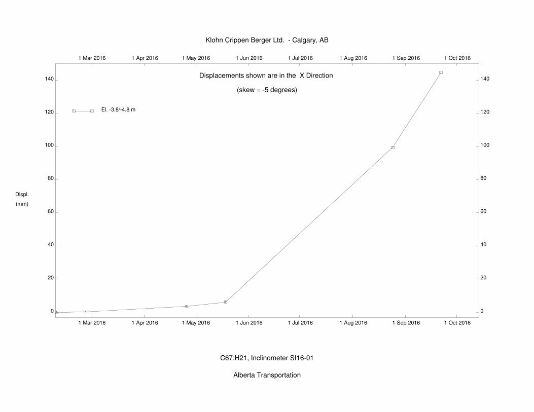
Slope inclinometer SI16-01 was installed and initialized on February 9, 2016 at Site A, with a second SI (SI16-02) being installed on November 8, 2016 and initialized on November 29, 2016 at Site B. SI16-01 has been read 6 times since installation, with a total of 144 mm of movement being recorded at a depth of 4.5 m (El. 803.7 m). Slope Inclinometer plots for cumulative displacement, incremental displacement, and displacement vs time are attached in Appendix III. SI16-02 was read on January 5, 2017 but requires additional readings over the coming months to verify the failure plane location, the cumulative displacement plot is attached in Appendix III. SI16-02 is scheduled to be read twice more the end of January to determine if a failure plane location can be identified. It is intended to read the SI every two weeks thereafter to verify the failure depth and rate of movement.
The water level recorded in SP16-01 was measured at 11.7 m below ground surface (El. 796.50 m) on January 5, 2017. It has been noted that this instrument was installed too deep as it does not record the ground water located near the base of the slide. The two piezometers (SP16-02 and SP16-03) that were installed in November 2016 were designed to span across the failure surfaces at both Site A and Site B to record ground water levels at the depth of the failure plane.
The standpipe at Site A was installed over the identified failure plane identified in SI16-01. The standpipe at Site B was installed in an area determined by stability back analysis to be the region where the failure plane is estimated to be located. Both standpipes were measured to be dry at the time of installation and when last read on January 5, 2017.

Alberta Transportation Site C67 – H21:14, km 12.8 Slope Failure Rehabilitation
Options Assessment Report Draft
170106 C67 Hwy 21 Slope Options Report_Draft.docx
Page 5
A05115B02 January 2017
The groundwater conditions within the slope will vary with the seasons and also in response to periods of wet and dry weather. As stated earlier, there is a potential for buried springs in the slope that may only be active during periods of heavy rainfall and wet weather.
2.4 Laboratory Testing
Laboratory testing was not done as part of the February 2016 geotechnical investigation due to budget constraints. Laboratory testing on select samples collected during the November 2016 investigation is underway and completed results were not available at the time of preparation of this report. The results will be available for use in the final design phase and used to verify the accuracy of the visual description of the encountered soil conditions presented on the borehole logs.
The current laboratory testing program consists of:
Atterberg Limits - Standard Test Methods for Liquid Limit, Plastic Limit, and Plasticity Index of Soils (ASTM D4318);
Moisture Content - Standard Test Methods for Laboratory Determination of Water (Moisture) Content of Soil by Mass (ASTM D2216-10);
Hydrometer - Standard Test Method for Particle-Size Analysis of Soils (ASTM D422-63); and
Sieve - Standard Test Methods for Particle-Size Distribution (Gradation) of Soils Using Sieve Analysis (ASTM D6913-04).
The results of this laboratory testing program will be used to develop material parameters for use in the geotechnical design of the selected repair option.

Alberta Transportation Site C67 – H21:14, km 12.8 Slope Failure Rehabilitation
Options Assessment Report Draft
170106 C67 Hwy 21 Slope Options Report_Draft.docx
Page 6
A05115B02 January 2017
3 SUBSURFACE CONDITIONS
3.1 Regional Geology Setting
The surficial geology at the site is classified as late glacial and early post-glacial lake deposits (Stalker, 1973). These deposit are classified into fine and coarse materials. The site lies within the fine material area, with the area described as poorly sorted silt and clay, with local deposits of sand and pebbles, that was typically deposited by slow-flowing streams.
3.2 2016 Geotechnical Site Characterization
Based on the available geotechnical information, the following section summarizes the encountered ground conditions, from surface to depth, for the site. The general stratigraphy is as follows:
Fill Clay Till Silt
Based on rural highway construction techniques previously used in Alberta, the embankment fill used to construct the highway above natural ground is not always uniform material and can vary significantly between sections of highway. A clear contact between the embankment fill and natural ground was not encountered in any of the boreholes, likely due to the nature of construction and that the fill used was excavated from the above natural embankment slope. Cut materials from the backslope are likely similar to the foundation materials below the fill which complicates identifying the fill-foundation contact. Figures 3 and 4 show sections of Site A and Site B with the estimated original ground surface plotted.
3.2.1 Embankment Fill
The embankment fill material used to construct the highway was found to be similar to the foundation materials below. As stated above, a clear contact between the fill and foundation materials was not encountered. The material encountered from ground surface down to what is estimated to be original ground surface was described as clay and silt, trace to some fine grained sand, trace gravel, light brown to dark brown in colour, dry to wet.
SPT N values ranged from 4 (soft) to 12 (stiff). Pocket penetrometer measurements performed in the field showed an undrained shear strength (Su) that ranged from 12 kPa to 137 kPa.
3.2.2 Clay Till
Clay till was encountered in all boreholes extending from what is estimated to be natural ground level, at a thickness ranging from approximately 4.5 m (SI16-01) to 10.5 m (SI16-02) which was the bottom of the borehole. The clay till is generally described as silty to some silt, trace to some sand (medium to coarse grained), trace gravel, brown to grey in colour, and moist.
SPT N values ranged from 3 (soft) to 12 (stiff). Pocket penetrometer measurements performed on the clay till in the field showed an undrained shear strength (Su) that ranged from 12 kPa to 87 kPa.

Alberta Transportation Site C67 – H21:14, km 12.8 Slope Failure Rehabilitation
Options Assessment Report Draft
170106 C67 Hwy 21 Slope Options Report_Draft.docx
Page 7
A05115B02 January 2017
3.2.3 Silt
Silt was encountered in SI16-01, at a depth of 8.8 m to the bottom of the hole. The silt is generally described as clayey to some clay, light brown to grey in colour, soft to firm, and moist.

Alberta Transportation Site C67 – H21:14, km 12.8 Slope Failure Rehabilitation
Options Assessment Report Draft
170106 C67 Hwy 21 Slope Options Report_Draft.docx
Page 8
A05115B02 January 2017
4 REHABILITATION OPTIONS
4.1 General
Two design concepts have been considered for the rehabilitation and repair of the two slide areas at Site C67. The two repair options include:
Option 1 - Excavating and replacing the embankment material to 1.0 m below the depth of the slide, including the installation of a shear key and drainage down the slope; and
Option 2 - Installing a pile wall on the crest of the slope, off the southbound highway lane shoulder, to a depth of approximately three times the depth of the slide.
These design concepts that have been developed with preliminary analysis that will be confirmed when the laboratory program is completed. Final design will include analysis to prepare design details using all available information.
The rehabilitation engineering options are shown on Figure 5 to Figure 9 and discussed in following sections.
4.2 Design Basis Memorandum
The Design Basis Memorandum (DBM) documents the criteria, assumptions, methodologies, and references to be used in the Final Design of the slope repair at Site C67. The DBM will be updated as the design phase evolves, and it will ultimately be incorporated into the final design submission. It is included in Appendix IV.
Some design constraints to be considered in the rehabilitation options and design include:
Construction Schedule - The highway in this area is scheduled for a new overlay construction to be undertaken in May 2017. All construction activities must be complete before this date.
Weather Constraints – Due the construction being required to be completed by May 2017, it is likely that the slope rehabilitation construction will need to be completed in the winter/freezing conditions.
Traffic Volumes and Lane Closures – Due to the high volume of traffic on Highway 21 construction activities should be scheduled to limit the extent and duration of any highway closures.

Alberta Transportation Site C67 – H21:14, km 12.8 Slope Failure Rehabilitation
Options Assessment Report Draft
170106 C67 Hwy 21 Slope Options Report_Draft.docx
Page 9
A05115B02 January 2017
4.3 Rehabilitation Options Discussion
A summary of the rehabilitation options considered by KCB is presented in Table 4.1.
Table 4.1 Engineering Options Summary
Option Figures Features Advantages Disadvantages
Option 1 Excavate and
replace 5, 6, 7
Excavation and replacement of the material below the road surface down to beneath the failure plane.
Excavate a shear key to below failure plane into intact competent material.
Install finger drains down the slope that will de-water the failure area and assist in addressing issues caused by any buried springs that may have been covered during original highway construction.
The excavated slide area and finger drains will be infilled with gravel to reinstate the road surface.
Potentially less settlement after completed construction.
Higher factor of safety then pile option due to the removal of the shear plane and replacing with high strength gravel.
Gravel fill and finger drains installed down the natural slope will improve drainage under the highway and lower the water table in the spring and summer months.
Construction expected to take longer than pile installation. Estimate approximately 2 to 3 weeks per site to complete construction.
Materials will be susceptible to freezing that could hinder construction and cause future settlement issues.
Large portion of the highway will be required to be closed during construction activities. Traffic delays associated with complete closure of the highway and single lane gravel detours on a busy highway will complicate traffic accommodation.
Option 2 Pile Wall
8, 9
Installation of pile walls at the crest of the failing slopes. Piles will be installed off the shoulder of the southbound highway lane.
Based on an initial assessment, at Site A, a pile wall located at the crest of the slope will be required to extend approximately 15 m deep to ensure that approximately 2/3 the pile embedment length (cantilever) is below the failure plane (5 m deep).
Site B’s failure surface has not been identified as there has not been enough readings taken to clearing identify a failure surface.
Construction can be undertaken from the highway.
Relatively quick construction time compared to earthworks. Estimate approximately 10 to 14 days per site to complete installation.
The ability for winter construction without the issues of backfill materials freezing.
Potentially only required the closure of one lane, leaving two lanes open to accommodate traffic.
The option to install tie-back anchors in the future can be included to help mitigate the risk of unloading of the passive resistance from the face.
Cantilever and tied-back pile walls have been constructed by AT throughout Alberta, the pile types have varied from driven steel to cast-in-place while the tie-backs have consisted predominately of grouted and screwed anchors (Abdelazziz et. al., 2011).
May not fully arrest movement of the slope below the wall leading to loss of passive support to the wall.
Piles are designed using active earth pressure and as such deflections should be expected in the order of 200 mm at the head of the pile. Higher than typical maintenance of the highway should be expected during this mobilization period - it typically takes 3 to 4 years for the piles to mobilize the stabilizing force.
Additional drainage measures may be required as an increase in the water table during the spring and summer months are thought to play a role in the slope instability.
The depth to failure at Site B has not been defined. Due to the higher fill at Site B, the slide depth may be greater and a pile wall with tie back anchors may be required.

Alberta Transportation Site C67 – H21:14, km 12.8 Slope Failure Rehabilitation
Options Assessment Report Draft
170106 C67 Hwy 21 Slope Options Report_Draft.docx
Page 10
A05115B02 January 2017
Based on the lack of movement data in the SI at Site B, it is unknown at what depth the failure surface is beneath the highway. At this time, KCB will process with final design based on the knowledge of the slide area at Site A and revise as more data is obtained. The identification of the depth of the failure surface at Site B will not change the overall design but will change the required depth of excavation, length of piles installed, and/or the need for tie-back anchors to be installed.
If no failure surface is identified at Site B before construction tendering is required, final design can proceed under the assumption of a failure surface depth. If this is chosen, the slope performance can be monitored and additional measures taken if necessary (such as the provision to install tie-back anchors at a later date).
4.4 Rehabilitation Options Cost Estimates
Preliminary quantities and cost estimates, based on the preliminary design options, described above were also prepared. The unit costs are based on material costs taken from AT’s Unit Price Averages (Central Region).
The estimated preliminary costs for the construction of Option 1 at Site A is provided in Table 4.2.
Table 4.2 Option 1 (Site A) – Excavate and Replace Slide Area Cost Estimate
Item Unit Unit Price Quantity Cost ($) Notes
Mob and Demob L.S. L.S. L.S. 30,000
Site Occupancy days $800 21 $16,800
B152 - Granular Fill (Pit-run) – Des. 6
m3 $46.46 5,000 $232,300
G225 - Common Excavation m3 $7.47 5200 $38,844
Re-use Excavated Clay m3 $7.47 600 $4,482
Load and Haul Away Excess Clay
m3 $18.00 4600 $82,800 estimate for excavation, hauling and disposal
E453 – Geogrid (Supply and Install)
m2 $6.16 2500 $15,400
E452 – Geotextile – Nonwoven (Supply and Install)
m2 $3.95 700 $2,765
D615 - Perforated Pipe m $168.33 600 $100,998
unit price from C69 repair was $45/m
Asphalt removal and disposal m3 $50.00 400 $20,000
estimate for excavation, hauling and disposal
Q990 - Asphalt replacement m3 $167.03 200 $33,406
S820 - Remove, Salvage and Reinstall Existing Guardrail
m $116.65 100 $11,665
S770 - Supply and Install Wooden Posts
Posts $244.88 40 $9,795
G300 - Topsoil Placement m2 $1.02 500 $510
Traffic Accommodation - Incidental to unit rates
Construction Control Survey - Incidental to unit rates
ECO Plan - Incidental to unit rates

Alberta Transportation Site C67 – H21:14, km 12.8 Slope Failure Rehabilitation
Options Assessment Report Draft
170106 C67 Hwy 21 Slope Options Report_Draft.docx
Page 11
A05115B02 January 2017
Item Unit Unit Price Quantity Cost ($) Notes
Total Total $599,765
10% contingency $59,977
+10% contingency
$659,742
1 Due to the scheduled highway overlay construction, this item can be removed.
The estimated preliminary costs for the construction of Option 2 at Site A is provided in Table 4.3.
Table 4.3 Option 2 (Site A)– Pile Wall
Item Unit Unit Price Quantity Cost ($) Notes
Mob and Demob L.S. L.S. L.S. 30,000
Site Occupancy days $800 14 $11,200
F812 – Supply of H- Pile (HP360 X132)
m $144.58 1800 $260,244
F818 - Pile Driving m $85.94 1800 $154,692
F816 – Pile Set-up pile $1,663.96 120 $199,675
Waler Beam - Supply and Install
L.S. L.S. L.S. $60,000 price based on C07 repair
S820 - Remove, Salvage and Reinstall Existing Guardrail
m $116.65 100 $11,665
S770 - Supply and Install Wooden Posts
Posts $244.88 35 $8,571
Traffic Accommodation - Incidental to unit rates
Construction Control Survey - Incidental to unit rates
ECO Plan - Incidental to unit rates
Total Total $736,047
10% contingency $73,605
+10% contingency
$809,652
The cost estimates prepared for Site B are based on an assumed failure surface depth similar to what was identified at Site A. These costs could change based on the depth of the failure surface once more SI readings have been taken and the failure surface has been identified.
The estimated preliminary costs for the construction of Option 1 at Site B is provided in Table 4.4.
Table 4.4 Option 1 (Site B) – Excavate and Replace Slide Area Cost Estimate
Item Unit Unit Price Quantity Cost ($) Notes
Mob and Demob L.S. L.S. L.S. - included in Site A
Site Occupancy days $800 14 $11,200
B152 - Granular Fill (Pit-run) – Des. 6
m3 $46.46 2,500 $116,150
G225 - Common Excavation m3 $7.47 2600 $19,422
Re-use Excavated Clay m3 $7.47 400 $2,988
Load and Haul Away Excess Clay
m3 $18.00 2300 $41,400 estimate for excavation, hauling and disposal
Alberta Transportation Site C67 – H21:14, km 12.8 Slope Failure Rehabilitation
Options Assessment Report Draft
170106 C67 Hwy 21 Slope Options Report_Draft.docx
Page 12
A05115B02 January 2017
Item Unit Unit Price Quantity Cost ($) Notes
E453 – Geogrid (Supply and Install)
m2 $6.16 1300 $8,008
E452 – Geotextile – Nonwoven (Supply and Install)
m2 $3.95 400 $1,580
D615 - Perforated Pipe m $168.33 400 $67,332 unit price from C69 repair was $45/m
Asphalt removal and disposal m3 $50.00 200 $10,000 estimate for excavation, hauling and disposal
Q990 - Asphalt replacement m3 $167.03 100 $16,703
S820 - Remove, Salvage and Reinstall Existing Guardrail
m $116.65 50 $5,833
S770 - Supply and Install Wooden Posts
Posts $244.88 15 $3,673
G300 - Topsoil Placement m2 $1.02 300 $306
Traffic Accommodation - Incidental to unit rates
Construction Control Survey - Incidental to unit rates
ECO Plan - Incidental to unit rates
Total Total $304,595
10% contingency $30,459
+10%
contingency $335,054
1 Due to the scheduled highway overlay construction, this item can be removed.
The estimated preliminary costs for the construction of Option 2 at Site b is provided in Table 4.5.
Table 4.5 Option 2 (Site B) – Pile Wall
Item Unit Unit Price Quantity Cost ($) Notes
Mob and Demob L.S. L.S. L.S. - included in Site A
Site Occupancy days $800 10 $8,000
F812 – Supply of H- Pile (HP360 X132)
m $144.58 900 $130,122
F818 - Pile Driving m $85.94 900 $77,346
F816 – Pile Set-up pile $1,663.96 60 $99,838
Waler Beam - Supply and Install
L.S. L.S. L.S. $30,000 price based on C07 repair
S820 - Remove, Salvage and Reinstall Existing Guardrail
m $116.65 50 $5,833
S770 - Supply and Install Wooden Posts
Posts $244.88 15 $3,673
Traffic Accommodation - Incidental to unit rates
Construction Control Survey - Incidental to unit rates
ECO Plan - Incidental to unit rates
Total Total $354,811
10% contingency $35,481
+10% contingency
$390,292

Alberta Transportation Site C67 – H21:14, km 12.8 Slope Failure Rehabilitation
Options Assessment Report Draft
170106 C67 Hwy 21 Slope Options Report_Draft.docx
Page 13
A05115B02 January 2017
5 SUMMARY
The highway section at Site C67 is scheduled to be re-paved in May 2017, therefore it is required that the chosen rehabilitation option be suitable for winter construction. Based on this it is recommended that “Option 2 – Pile Wall” be chosen due to the fact that pile installation can be undertaken in any season and will not be affected by freezing ground conditions that would affect earth works construction activities. The pile wall will also be able to be constructed in a shorter time frame, which will limit the amount of time that Highway 21 is affected by construction activities.

Alberta Transportation Site C67 – H21:14, km 12.8 Slope Failure Rehabilitation
Options Assessment Report Draft
170106 C67 Hwy 21 Slope Options Report_Draft.docx
Page 14
A05115B02 January 2017
6 CLOSING
This report is an instrument of service of Klohn Crippen Berger Ltd. The report has been prepared for the exclusive use of Alberta Transportation (AT) for the specific application to the C67 Highway 21 Slope Failure Rehabilitation. The report's contents may not be relied upon by any other party without the express written permission of Klohn Crippen Berger. In this report, Klohn Crippen Berger has endeavoured to comply with generally-accepted professional practice common to the local area. Klohn Crippen Berger makes no warranty, express or implied.
The analyses, conclusions and recommendations contained in this report are based on data derived from a limited number of test holes obtained from widely spaced subsurface explorations. The methods used indicate subsurface conditions only at the specific locations where samples were obtained or where in-situ tests would infer, only at the time they were obtained, and only to the depths penetrated. The samples and tests cannot be relied on to accurately reflect the nature and extent of strata variations that usually exist between sampling or testing locations.
The recommendations included in this report have been based in part on assumptions about strata variations between test holes that will not become evident until construction or further investigation. Accordingly, Klohn Crippen Berger should be retained to perform construction observation and thereby provide a complete professional geotechnical engineering service through the observational method. If variations or other latent conditions become evident during construction, Klohn Crippen Berger will re-evaluate this report's recommendations. Klohn Crippen Berger cannot assume responsibility or liability for the adequacy of its recommendations when they are used in the field without Klohn Crippen Berger being retained to observe construction.
Although Klohn Crippen Berger has explored subsurface conditions as part of this program, Klohn Crippen Berger has not conducted analytical laboratory testing of samples obtained, has not evaluated the site for potential presence of contaminated soil, and has not evaluated groundwater conditions.
The recommendations presented in this document are subject to change by KCB as new information becomes available. The reader should confirm with Klohn Crippen Berger Ltd. that information contained in this report has not been superseded before applying these recommendations to the planning work for the project.
Alberta Transportation Site C67 – H21:14, km 12.8 Slope Failure Rehabilitation
Options Assessment Report Draft
170106 C67 Hwy 21 Slope Options Report_Draft.docx
Page 15
A05115B02 January 2017
We trust this report meets your current requirements. Please contact the undersigned if you have any questions. KLOHN CRIPPEN BERGER LTD. Peter Roy, P.Eng. Andy Brunsdon, P.Eng. Civil Engineer Senior Civil Engineer cc: Chris Gräpel, P.Eng.
Alberta Transportation Site C67 – H21:14, km 12.8 Slope Failure Rehabilitation
Options Assessment Report Draft
170106 C67 Hwy 21 Slope Options Report_Draft.docx
Page 16
A05115B02 January 2017
REFERENCES
Klohn Crippen Berger (2016). Central Region Geohazard Assessment, Site C67 H21: 14 km 12.8 Kneehill Creek Side, Site Investigation and Instrumentation Report. March 10, 2016.
Stalker, A M (1973). Surficial Geology of the Drumheller area, Alberta; Geological Survey of Canada, Memoir 370, 1973

Alberta Transportation Site C67 – H21:14, km 12.8 Slope Failure Rehabilitation
Options Assessment Report Draft
170106 C67 Hwy 21 Slope Options Report_Draft.docx
A05115B02 January 2017
FIGURES

N.W. 1/4 Sec. 19
29-23-4
C
U
L
V
E
R
T
0
.
7
5
Ø
C
S
I
N
V
=
8
0
3
.
7
0
A
A
H
W
Y
5
7
5
H
W
Y
2
1
Site A Location
SITE LOCATION PLAN
N.T.S
NOTES
- ELEVATIONS ARE IN METRES
- SURVEY COMPLETED NOV 11, 2015 BY CHALLENGER
GEOMATICS LTD.
- ALL COORDINATES AND BEARINGS ARE REFERRED TO
UTM ZONE 12 NAD 83 (CSRS) EPOCH 2002.
LEGEND
SLOPE INCLINOMETER
STANDPIPE PIEZOMETER
BOREHOLE
B
B
H
W
Y
5
7
5
H
W
Y
2
1
Site B Location
SITE LOCATION PLAN
N.T.S
NOTES
- ELEVATIONS ARE IN METRES
- SURVEY COMPLETED OCT 31, 2016 BY CHALLENGER
GEOMATICS LTD.
- ALL COORDINATES AND BEARINGS ARE REFERRED TO
UTM ZONE 12 NAD 83 (CSRS) EPOCH 2002.
LEGEND
SLOPE INCLINOMETER
STANDPIPE PIEZOMETER

Elevation (m
)
Elevation (m
)
SECTIONA

Elevation (m
)
SECTIONB

N.W. 1/4 Sec. 19
29-23-4
D
C
NOTES
- ELEVATIONS ARE IN METRES
- SURVEY COMPLETED NOV 11, 2015 BY CHALLENGER
GEOMATICS LTD.
- ALL COORDINATES AND BEARINGS ARE REFERRED TO
UTM ZONE 12 NAD 83 (CSRS) EPOCH 2002.

Elevation (m
)
Elevation (m
)
SECTIONC
1.0 m
HEIGHT VARIES
DRAIN DETAIL
DETAIL
150 mm DIA.
HDPE PIPE
WITH GEOSOCK
REUSE EXISTING
FILL TO CAP GRAVEL
NTS
5.5 m

Elevation (m
)
Elevation (m
)
5.5 m
SECTIOND
N.W. 1/4 Sec. 19
29-23-4
E
E
NOTES
- ELEVATIONS ARE IN METRES
- SURVEY COMPLETED NOV 11, 2015 BY CHALLENGER
GEOMATICS LTD.
- ALL COORDINATES AND BEARINGS ARE REFERRED TO
UTM ZONE 12 NAD 83 (CSRS) EPOCH 2002.

Elevation (m
)
Elevation (m
)
SECTIONE

Alberta Transportation Site C67 – H21:14, km 12.8 Slope Failure Rehabilitation
Options Assessment Report Draft
170106 C67 Hwy 21 Slope Options Report_Draft.docx
A05115B02 January 2017
APPENDIX I
Site Inspection Reports

CENTRAL REGION GEOHAZARD RISK ASSESMENT
SITE INSPECTION FORM
Page 1 of 1
SITE NUMBER AND NAME C67 Kneehill Creek Slide
HIGHWAY & KM H21:14 km 12.988
PREVIOUS INSPECTION DATE October 7, 2015
INSPECTION DATE
June 23, 2016
LEGAL DESCRIPTION NW 19-29-23-W4
NAD 83 COORDINATES Northing
51°29.920' Easting
113°14.051'
RISK ASSESSMENT PF: 11 CF: 5 TOTAL: 55
Average Annual Daily Traffic (AADT): 1,770
Contract Maintenance Area (CMA): 20
SUMMARY OF SITE INSTRUMENTATION:
One slope inclinometer installed in 2016 One standpipe installed in 2016
LAST READING DATE: May 22, 2016
INSPECTED BY:
- Chris Gräpel (KCB) - Kurt Tomblin (KCB) - Roger Skirrow (AT) - Rocky Wang (AT)
PRIMARY SITE ISSUE: Two areas where there are embankment side hill fill settlement/slope failures. Site was location of ongoing settlement. Rate of movement increased in 2015 after heavy rainfall.
APPROXIMATE DIMENSIONS: 2 areas: 80 m and approximately 30 m long on highway. Slopes are approximately 15 m high and sloped at 4H:1V.
DATE OF ANY REMEDIAL ACTION: Asphalt patching conducted annually for several years.
ITEM CONDITION EXISTS DESCRIPTION AND LOCATION
NOTICABLE CHANGE FROM LAST INSPECTION
YES NO YES NO
Pavement Distress X Cracking extending past centreline (3 lanes, 2 northbound), failure in southbound lane
Slope Movement X Minor bulge noted at centre of slide area about 5 m below highway.
Erosion X
Seepage X
Culvert Distress X
COMMENTS
SI has recorded movements located approximately 4.5 m below edge of pavement.
Appears to be a side hill fill failure where poorly compacted materials were placed on the valley slope, possibly over springs.
Proposal submitted to AT in June 2016 for investigation, design of repairs, tendering, construction management.

File: \\i
nt.kloh
n.com
\ProjD
ata\A\
EDM\A
05115A
02 AB
T Cen
tral Re
gion G
RMP\4
00 Dra
wings\
C067\
160729
C067.
mxd
NOT FOR CONSTRUCTION
CENTRAL REGION GEOHAZARD RISK MANAGEMENT PROGRAM
C067 H21:14 km 12.988 Site Plan
A05115A02 1
PROJECT
TITLE
PROJECT No. FIG No.
CLIENT
³
0 200Meters
1. HORIZONTAL DATUM: NAD832. GRID ZONE: UTM Zone 12N3. IMAGE SOURCE: Bing Maps 2016, Microso ft Corporation. Image dated August 2013
SCALE
NOTES:
Time: 1
3:44:4
4 PM
Date:
July 2
9, 2016
1:3,000
_̂
_̂
UV12
UV56
UV9
UV9
Legend"5 Slope Inclinometer +A Standpipe Piezometer
KKKKKK Crack
Approximate locationof cracking in highway
Approximate locationof cracking in highway
DHWY 21 to
JCT HWY 1
D
HWY 21 to Trochu
Surface Flow Direction
Alberta Transportation Central Region GRMP
C67 Kneehill Creek Slide H21:14 km 12.988
160802 C67 photos.docx
Page 1 A05115A02 August 2016
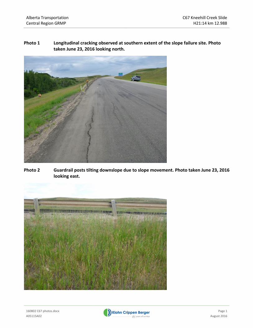
Photo 1 Longitudinal cracking observed at southern extent of the slope failure site. Photo taken June 23, 2016 looking north.
Photo 2 Guardrail posts tilting downslope due to slope movement. Photo taken June 23, 2016 looking east.

Alberta Transportation Central Region GRMP
C67 Kneehill Creek Slide H21:14 km 12.988
160802 C67 photos.docx
Page 2 A05115A02 August 2016
Photo 3 Longitudinal cracking observed adjacent to the slope inclinometer. Photo taken June 23, 2016 looking south.
Photo 4 Longitudinal cracking observed between the two northbound passing lanes. Photo taken June 23, 2016 looking north.

Alberta Transportation Site C67 – H21:14, km 12.8 Slope Failure Rehabilitation
Options Assessment Report Draft
170106 C67 Hwy 21 Slope Options Report_Draft.docx
A05115B02 January 2017
APPENDIX II
2016 Borehole Logs

807.90
799.40
797.60
792.96
0.30
8.80
10.60
15.24
Sand and Gravel (FILL)CLAY (CI)some silt, trace gravel, up to 10 mm, medium
plasticity, firm to stiff, brown, moist.
At 4.5 m: Medium to high plasticity clay, tracebentonite.
At 6.1 m: Some silt, increasing with depth.
SILT (ML)Clayey, soft to firm, light brown, moist.
SILT (ML)Some clay, soft, grey, moist.
From 11.9 m to 12.2 m: Silt lense, light brown, moist.
End of Hole at: 15.24 m
Test hole terminated at 15.24 m.15.3 m Slope Inclinometer installed0.97 m stickup.
HOLE NO.:
CHECKED BY: DR
SHEET 1 OF 1
PROJECT: 2015 Geohazards
PROJECT NO.: A03038C15
LOGGED BY: PR
LOCATION: Hwy 21 - 1 km south of Hwy 575 on west shoulder
SI16-01KC
_TE
ST
_HO
LE-S
I 20
1602
08 H
WY
21
LOG
S.G
PJ
KC
BL_
CA
LGA
RY
.GD
T
6-1-
17
1
2
3
4
5
6
7
8
9
10
11
12
13
14
15
16
17
18
19
20
Solid Stem AugerPEAK
DRILL METHOD:
GROUND ELEV. (m):
DE
TA
ILS
INS
TR
UM
EN
T
STARTED: FINISHED:D
EP
TH
(m
)FIELD
808.20
20 40 60 80DESCRIPTION OF MATERIALS
TEST HOLE LOG
SP
T B
LOW
S
LAB
P.PEN/2
LW%W %
REMOLD
VANE
SA
MP
LE N
o.
SA
MP
LE T
YP
E
Feb 9, 2016
Su - kPa
20 60 100 140 180
UC/2
SY
MB
OL
% FINES SPT N
P W %COORDINATES (m): E 344910N 5707640
Feb 9, 2016

792.9615.24
Not Lgged
For soil descriptions see SI16-01
End of Hole at: 15.24 m
Test hole terminated at 15.24 m.14 m standpipe installed.0.7 m stick up.
HOLE NO.:
CHECKED BY: DR
SHEET 1 OF 1
PROJECT: 2015 Geohazards
PROJECT NO.: A03038C15
LOGGED BY: PR
LOCATION: Hwy 21 - 1 km south of Hwy 575 on west shoulder
SP16-01KC
_TE
ST
_HO
LE-S
I 20
1602
08 H
WY
21
LOG
S.G
PJ
KC
BL_
CA
LGA
RY
.GD
T
6-1-
17
1
2
3
4
5
6
7
8
9
10
11
12
13
14
15
16
17
18
19
20
Solid Stem AugerPEAK
DRILL METHOD:
GROUND ELEV. (m):
DE
TA
ILS
INS
TR
UM
EN
T
STARTED: FINISHED:D
EP
TH
(m
)FIELD
808.20
20 40 60 80DESCRIPTION OF MATERIALS
TEST HOLE LOG
SP
T B
LOW
S
LAB
P.PEN/2
LW%W %
REMOLD
VANE
SA
MP
LE N
o.
SA
MP
LE T
YP
E
Feb 9, 2016
Su - kPa
20 60 100 140 180
UC/2
SY
MB
OL
% FINES SPT N
P W %COORDINATES (m): E 344910N 5707640
Feb 9, 2016

829.70
828.50
825.12
824.50
822.10
GB-01
GB-02
GB-03
GB-04
GB-05
GB-06
Grab
Grab
Grab
Grab
Grab
Grab
0.30
1.50
4.88
5.50
7.90
4/5/6
5/5/7
3/3/4
4/5/7
3/4/5
3/3/4
Gravel and Asphalt
CLAY (CI)Some silt, trace sand, medium plasticity, brown, stiff,
moist.
SILT (ML)Some clay, brown, firm to stiff, moist.
From 2.75 m to 3.35 m: Dark brown, firm to very stiff.
From 3.35 m to 4.27 m: Light brown, soft, dry, someclay pockets up to 40 mm.
From 4.27 m to 4.57 m: Dark brown, firm.
From 4.57 m to 4.88 m: Light brown, soft, dry.
CLAY and SILT (CI-ML)Dark brown, stiff, moist
CLAY (CI)Some silt, dark brown, medium plasticity, firm to stiff,
moist.
CLAY (CI-CH)Trace silt, medium to high plasticity, grey, firm,
moist. Becoming softer with depth.
HOLE NO.:
CHECKED BY:
Continued Next Page
SG
SHEET 1 OF 2
PROJECT: Site C67 Hwy 21 Slope Failure
PROJECT NO.: A05115B02
LOGGED BY: PR
LOCATION: Hwy 21 - South of Hwy 575
SI16-02KC
_TE
ST
_HO
LE-S
I 20
1611
08 H
WY
21
LOG
S.G
PJ
KC
BL_
CA
LGA
RY
.GD
T
6-1-
17
1
2
3
4
5
6
7
8
9
10
Solid Stem AugerPEAK
DRILL METHOD:
GROUND ELEV. (m):
DE
TA
ILS
INS
TR
UM
EN
T
STARTED: FINISHED:D
EP
TH
(m
)FIELD
830.00
20 40 60 80DESCRIPTION OF MATERIALS
TEST HOLE LOG
SP
T B
LOW
S
LAB
P.PEN/2
LW%W %
REMOLD
VANE
SA
MP
LE N
o.
SA
MP
LE T
YP
E
Nov 8, 2016
Su - kPa
20 60 100 140 180
UC/2
SY
MB
OL
% FINES SPT N
P W %COORDINATES (m): E 344700N 5708070
Nov 8, 2016

818.11
814.70
GB-07
GB-08
GB-09
Grab
Grab
Grab
11.89
15.30
2/3/3
3/5/7
3/6/6
CLAY and SILT (CI-ML)Trace sand and gravel, grey, soft to stiff, moist.
End of Hole at: 15.3 m
Test hole teminated at 15.3 m.14 m SI installed.0.72 m stickup.
HOLE NO.:
CHECKED BY: SG
SHEET 2 OF 2
PROJECT: Site C67 Hwy 21 Slope Failure
PROJECT NO.: A05115B02
LOGGED BY: PR
LOCATION: Hwy 21 - South of Hwy 575
SI16-02KC
_TE
ST
_HO
LE-S
I 20
1611
08 H
WY
21
LOG
S.G
PJ
KC
BL_
CA
LGA
RY
.GD
T
6-1-
17
11
12
13
14
15
16
17
18
19
20
Solid Stem AugerPEAK
DRILL METHOD:
GROUND ELEV. (m):
DE
TA
ILS
INS
TR
UM
EN
T
STARTED: FINISHED:D
EP
TH
(m
)FIELD
830.00
20 40 60 80DESCRIPTION OF MATERIALS
TEST HOLE LOG
SP
T B
LOW
S
LAB
P.PEN/2
LW%W %
REMOLD
VANE
SA
MP
LE N
o.
SA
MP
LE T
YP
E
Nov 8, 2016
Su - kPa
20 60 100 140 180
UC/2
SY
MB
OL
% FINES SPT N
P W %COORDINATES (m): E 344700N 5708070
Nov 8, 2016

804.50
798.40
GB-01
GB-02
Grab
Grab
1.20
7.30
3/4/5
3/4/6
2/3/3
1/2/3
1/1/2
CLAY (CI)some silt, trace gravel, up to 10 mm, medium
plasticity, firm to stiff, brown, moist.
CLAY (CI)some silt, trace gravel, up to 10 mm, medium
plasticity, firm to stiff, brown, moist. Silt layers upto 0.2 m thick, brown, moist, soft.
End of Hole at: 7.3 m
Test hole terminated at 7.3 m.6.1 m standpipe installed.0.36 m stick up.
HOLE NO.:
CHECKED BY: SG
SHEET 1 OF 1
PROJECT: Site C67 Hwy 21 Slope Failure
PROJECT NO.: A05115B02
LOGGED BY: PR
LOCATION: Hwy 21 - South of Hwy 575
SP16-02KC
_TE
ST
_HO
LE-S
I 20
1611
08 H
WY
21
LOG
S.G
PJ
KC
BL_
CA
LGA
RY
.GD
T
6-1-
17
1
2
3
4
5
6
7
8
9
10
Solid Stem AugerPEAK
DRILL METHOD:
GROUND ELEV. (m):
DE
TA
ILS
INS
TR
UM
EN
T
STARTED: FINISHED:D
EP
TH
(m
)FIELD
805.70
20 40 60 80DESCRIPTION OF MATERIALS
TEST HOLE LOG
SP
T B
LOW
S
LAB
P.PEN/2
LW%W %
REMOLD
VANE
SA
MP
LE N
o.
SA
MP
LE T
YP
E
Nov 8, 2016
Su - kPa
20 60 100 140 180
UC/2
SY
MB
OL
% FINES SPT N
P W %COORDINATES (m): E 344930N 5707620
Nov 8, 2016
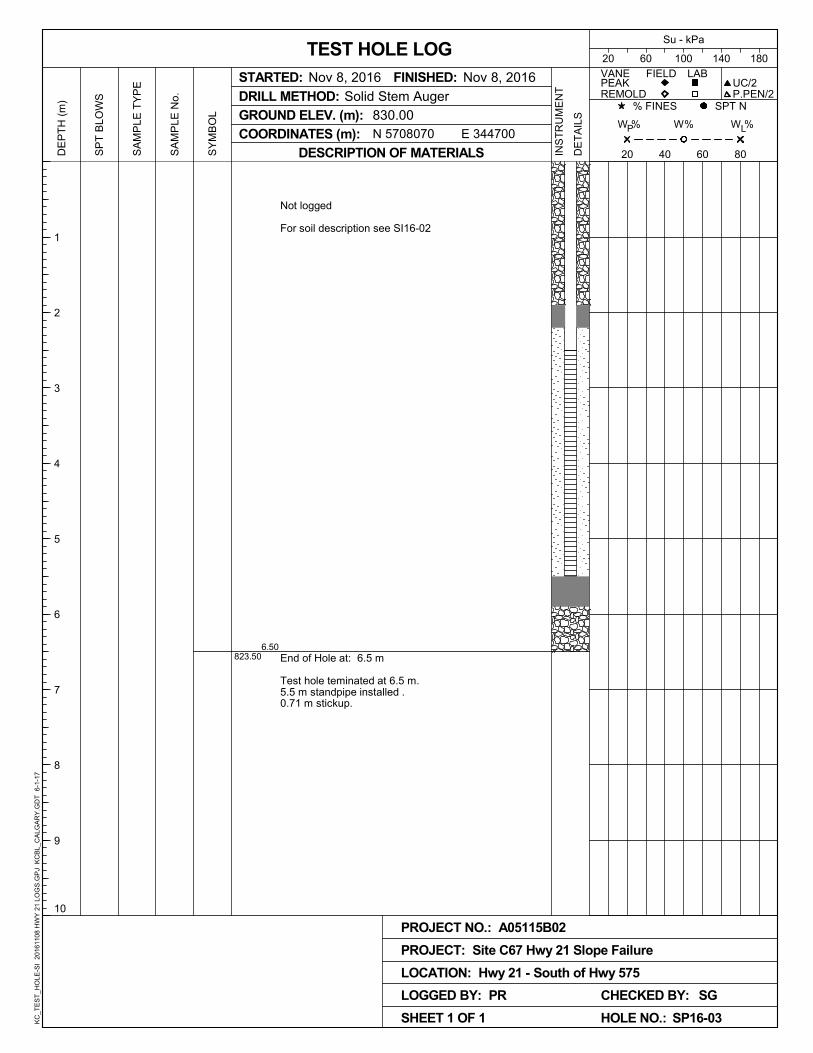
823.506.50
Not logged
For soil description see SI16-02
End of Hole at: 6.5 m
Test hole teminated at 6.5 m.5.5 m standpipe installed .0.71 m stickup.
HOLE NO.:
CHECKED BY: SG
SHEET 1 OF 1
PROJECT: Site C67 Hwy 21 Slope Failure
PROJECT NO.: A05115B02
LOGGED BY: PR
LOCATION: Hwy 21 - South of Hwy 575
SP16-03KC
_TE
ST
_HO
LE-S
I 20
1611
08 H
WY
21
LOG
S.G
PJ
KC
BL_
CA
LGA
RY
.GD
T
6-1-
17
1
2
3
4
5
6
7
8
9
10
Solid Stem AugerPEAK
DRILL METHOD:
GROUND ELEV. (m):
DE
TA
ILS
INS
TR
UM
EN
T
STARTED: FINISHED:D
EP
TH
(m
)FIELD
830.00
20 40 60 80DESCRIPTION OF MATERIALS
TEST HOLE LOG
SP
T B
LOW
S
LAB
P.PEN/2
LW%W %
REMOLD
VANE
SA
MP
LE N
o.
SA
MP
LE T
YP
E
Nov 8, 2016
Su - kPa
20 60 100 140 180
UC/2
SY
MB
OL
% FINES SPT N
P W %COORDINATES (m): E 344700N 5708070
Nov 8, 2016

807.30
805.45
802.40
GB-01
GB-02
Grab
Grab
1.20
3.05
6.10
3/5/5
1/2/2
2/2/4
2/3/4
CLAY (CI)some silt, trace gravel, up to 10 mm, brown, medium
plasticity, firm to stiff, moist.
SILT (SM)Some clay, brown, soft, moist.
At 2.1 m: becoming wet.
CLAY (CI)Trace silt, brownish grey, medium plastic, firm, moist.
End of Hole at: 6.1 m
HOLE NO.:
CHECKED BY: SG
SHEET 1 OF 1
PROJECT: Site C67 Hwy 21 Slope Failure
PROJECT NO.: A05115B02
LOGGED BY: PR
LOCATION: Hwy 21 - South of Hwy 575
BH16-01KC
_TE
ST
_HO
LE-S
I 20
1611
08 H
WY
21
LOG
S.G
PJ
KC
BL_
CA
LGA
RY
.GD
T
6-1-
17
1
2
3
4
5
6
7
8
9
10
Solid Stem AugerPEAK
DRILL METHOD:
GROUND ELEV. (m):
DE
TA
ILS
INS
TR
UM
EN
T
STARTED: FINISHED:D
EP
TH
(m
)FIELD
808.50
20 40 60 80DESCRIPTION OF MATERIALS
TEST HOLE LOG
SP
T B
LOW
S
LAB
P.PEN/2
LW%W %
REMOLD
VANE
SA
MP
LE N
o.
SA
MP
LE T
YP
E
Nov 8, 2016
Su - kPa
20 60 100 140 180
UC/2
SY
MB
OL
% FINES SPT N
P W %COORDINATES (m): E 344920N 5707650
Nov 8, 2016

Alberta Transportation Site C67 – H21:14, km 12.8 Slope Failure Rehabilitation
Options Assessment Report Draft
170106 C67 Hwy 21 Slope Options Report_Draft.docx
A05115B02 January 2017
APPENDIX III
Slope Inclinometer Plots

-13
-12
-11
-10
-9
-8
-7
-6
-5
-4
-3
-2
-1
0
Elev.
(m)
-200 -100 0 100 200
-13
-12
-11
-10
-9
-8
-7
-6
-5
-4
-3
-2
-1
0
-200 -100 0 100 200
-13
-12
-11
-10
-9
-8
-7
-6
-5
-4
-3
-2
-1
0
Elev.
(m)
-100 -50 0 50 100
-13
-12
-11
-10
-9
-8
-7
-6
-5
-4
-3
-2
-1
0
-100 -50 0 50 100
LEGEND
Initial 9 Feb 2016
26 Feb 2016
25 Apr 2016*
18 May 2016*
24 Aug 2016
21 Sep 2016
Cumulative Deflection
Direction A
Deflection (mm)
Cumulative Deflection
Direction B
Deflection (mm)
Ref. Elevation m
Z:\A\CGY\ALBERTA\A05115B02 ABT C67 HIGHWAY 21 SLOPE FAILURE\300 DESIGN\SI\SI16-01.GTL
C67:H21, Inclinometer SI16-01
Alberta Transportation
Sets marked * include zero shift and/or rotation corrections.
Klohn Crippen Berger Ltd. - Calgary, AB

-13
-12
-11
-10
-9
-8
-7
-6
-5
-4
-3
-2
-1
0
Elev.
(m)
-100 -50 0 50 100
-13
-12
-11
-10
-9
-8
-7
-6
-5
-4
-3
-2
-1
0
-100 -50 0 50 100
-13
-12
-11
-10
-9
-8
-7
-6
-5
-4
-3
-2
-1
0
Elev.
(m)
-10 -5 0 5 10
-13
-12
-11
-10
-9
-8
-7
-6
-5
-4
-3
-2
-1
0
-10 -5 0 5 10
LEGEND
Initial 9 Feb 2016
26 Feb 2016
25 Apr 2016*
18 May 2016*
24 Aug 2016
21 Sep 2016
Incremental Deflection
Direction X
Deflection (mm)
Incremental Deflection
Direction Y
Deflection (mm)
Ref. Elevation m
skew = -5deg
Z:\A\CGY\ALBERTA\A05115B02 ABT C67 HIGHWAY 21 SLOPE FAILURE\300 DESIGN\SI\SI16-01.GTL
C67:H21, Inclinometer SI16-01
Alberta Transportation
Sets marked * include zero shift and/or rotation corrections.
Klohn Crippen Berger Ltd. - Calgary, AB
140
120
100
80
60
40
20
0
Displ.
(mm)
140
120
100
80
60
40
20
0
1 Mar 2016 1 Apr 2016 1 May 2016 1 Jun 2016 1 Jul 2016 1 Aug 2016 1 Sep 2016 1 Oct 2016
1 Mar 2016 1 Apr 2016 1 May 2016 1 Jun 2016 1 Jul 2016 1 Aug 2016 1 Sep 2016 1 Oct 2016
El. -3.8/-4.8 m
Displacements shown are in the X Direction
(skew = -5 degrees)
C67:H21, Inclinometer SI16-01
Alberta Transportation
Klohn Crippen Berger Ltd. - Calgary, AB

-14
-12
-10
-8
-6
-4
-2
0
Elev.
(m)
-20 -10 0 10 20
-14
-12
-10
-8
-6
-4
-2
0
-20 -10 0 10 20
-14
-12
-10
-8
-6
-4
-2
0
Elev.
(m)
-20 -10 0 10 20
-14
-12
-10
-8
-6
-4
-2
0
-20 -10 0 10 20
LEGEND
Initial 28 Nov 2016
5 Jan 2017
Cumulative Deflection
Direction A
Deflection (mm)
Cumulative Deflection
Direction B
Deflection (mm)
Ref. Elevation m
Z:\A\CGY\ALBERTA\A05115B02 ABT C67 HIGHWAY 21 SLOPE FAILURE\300 DESIGN\SI\SI16-02.GTL
C67LH21, Inclinometer SI16-02
Alberta Transportation
Klohn Crippen Berger Ltd. - Calgary, AB

Alberta Transportation Site C67 – H21:14, km 12.8 Slope Failure Rehabilitation
Options Assessment Report Draft
170106 C67 Hwy 21 Slope Options Report_Draft.docx
A05115B02 January 2017
APPENDIX IV
Design Basis Memorandum

C67 HIGHWAY 21 SLOPE FAILURE REHABILITATION
Design Basis Memorandum (DBM)
CLIENT: ENGINEER:
Alberta Transportation GRMP – Central Region
20161223_DBM_C67 Hwy 21 Slope.docx
Revision / Issue
Date Description Prepared by
0 December 2016 Preliminary Draft - For Review PR

Alberta Transportation GRMP – Central Region
Design Basis Memorandum (DBM) Site C67 Highway 21 Slope Failure
TABLE OF CONTENTS
20161223_DBM_C67 Hwy 21 Slope.docx
Page i
A05115B02 December 2016
1 INTRODUCTION ............................................................................................................... 1 1.1 Background ............................................................................................................................... 1
1.1.1 Site A ............................................................................................................................. 1
1.1.2 Site B ............................................................................................................................. 2
2 DESIGN STANDARDS ........................................................................................................ 2
3 REFERENCE DATUM AND SURVEY DATA ............................................................................. 3
4 CONSTRUCTION SITE LIMITS AND REPAIR EXTENTS .......................................................... 3
5 DESIGN CONSTRAINTS ..................................................................................................... 3
6 GEOTECHNICAL DESIGN CRITERIA .................................................................................... 3 6.1 General ..................................................................................................................................... 3
6.2 Ground Conditions ..................................................................................................................... 4
6.3 Geotechnical Parameters ............................................................................................................ 5
6.4 Stability Assessments and Criteria ............................................................................................... 5
7 ENVIRONMENTAL CONSIDERATIONS ................................................................................. 6 7.1 Regulatory ................................................................................................................................ 6
7.2 Temporal Constraints ................................................................................................................. 7
8 CLOSURE ......................................................................................................................... 9

Alberta Transportation GRMP – Central Region
Design Basis Memorandum (DBM) Site C67 Highway 21 Slope Failure
20161223_DBM_C67 Hwy 21 Slope.docx
Page 1
A05115B02 December 2016
1 INTRODUCTION
This Design Basis Memorandum (DBM) presents the design criteria and assumptions which will be used for preparing the earthwork and civil designs for the repair of the C67- Highway 21 slope failure.
This is a working document which will be updated as new data becomes available and as the design progresses throughout the execution of the project. The contents reflect our current understanding of the project scope. All changes to the DBM will be documented and signed off by Klohn Crippen Berger Ltd. (KCB) and Alberta Transportation (AT).
1.1 Background
AT Central Region Geohazard Risk Monitoring Plan (GRMP) site C67 is located on H21:14 km 12.8, approximately 1 km south of Highway Junction 575 and approximately 700 m north of Kneehill Creek, near Carbon, Alberta. The site is located upslope of an unnamed ephemeral tributary creek to Kneehill Creek. The creek bed is located at the toe of the embankment slope. The highway was likely constructed as a side-hill embankment fill slope using material cut from the existing slope. The highway at this location includes two northbound lanes and one southbound lane.
The slide failures are likely caused by periods of heavy rainfall and the potential for buried springs in the slopes that are more active during periods of wet weather. During the summer of 2015 the central region of Alberta experienced greater than average amounts of precipitation. Weather stations at Wimbourne ACGM and Three Hills show that between 15 and 16 August 2015, approximately 45 mm of precipitation was recorded in the area, and for the month of August 2015 the area received more than twice the monthly average precipitation. The areas of distress are considered to be slow moving (creep movement) and likely represents transitional slides below the
highway. The slide at Site A was accelerated due to high precipitation levels causing the pavement to settled by a maximum amount of about 75 mm at the centreline of the highway. The slide at Site A was accelerated again in the summer of 2016 when the area received several heavy rainfall events with up to 42 mm of precipitation in 48 hours.
The legal description of the site is 12-19-029-23 W4. The 2015 Annual Average Daily Traffic (AADT) for H21 was 1770 (both directions) and is regularly used by heavily loaded vehicles. There are two slope failure areas which are described below.
The highway section at Site C67 is planned to be re-paved in the May 2017. The slope remediation must be complete by this date to allow for this work to go ahead as scheduled.
1.1.1 Site A
Site A, as shown on Figure 1, is located in a valley, approximately a quarter of the way up the east valley slope.
Alberta Transportation GRMP – Central Region
Design Basis Memorandum (DBM) Site C67 Highway 21 Slope Failure
20161223_DBM_C67 Hwy 21 Slope.docx
Page 2
A05115B02 December 2016
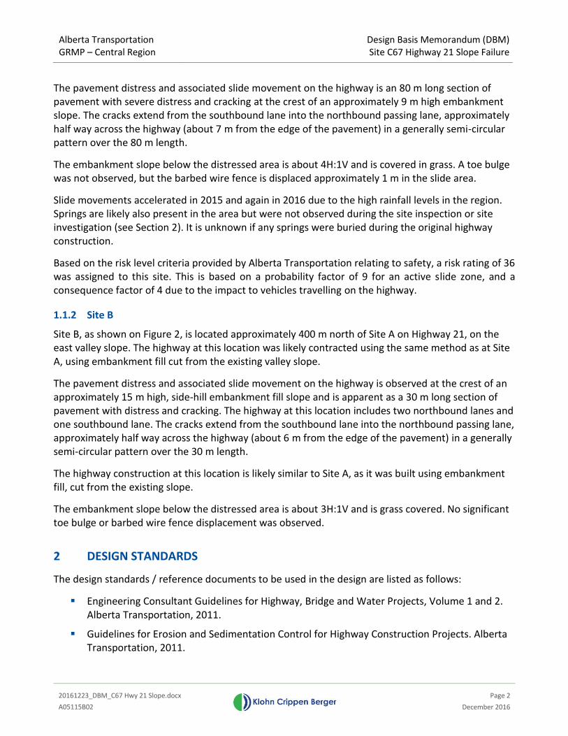
The pavement distress and associated slide movement on the highway is an 80 m long section of pavement with severe distress and cracking at the crest of an approximately 9 m high embankment slope. The cracks extend from the southbound lane into the northbound passing lane, approximately half way across the highway (about 7 m from the edge of the pavement) in a generally semi-circular pattern over the 80 m length.
The embankment slope below the distressed area is about 4H:1V and is covered in grass. A toe bulge was not observed, but the barbed wire fence is displaced approximately 1 m in the slide area.
Slide movements accelerated in 2015 and again in 2016 due to the high rainfall levels in the region. Springs are likely also present in the area but were not observed during the site inspection or site investigation (see Section 2). It is unknown if any springs were buried during the original highway construction.
Based on the risk level criteria provided by Alberta Transportation relating to safety, a risk rating of 36 was assigned to this site. This is based on a probability factor of 9 for an active slide zone, and a consequence factor of 4 due to the impact to vehicles travelling on the highway.
1.1.2 Site B
Site B, as shown on Figure 2, is located approximately 400 m north of Site A on Highway 21, on the east valley slope. The highway at this location was likely contracted using the same method as at Site A, using embankment fill cut from the existing valley slope.
The pavement distress and associated slide movement on the highway is observed at the crest of an approximately 15 m high, side-hill embankment fill slope and is apparent as a 30 m long section of pavement with distress and cracking. The highway at this location includes two northbound lanes and one southbound lane. The cracks extend from the southbound lane into the northbound passing lane, approximately half way across the highway (about 6 m from the edge of the pavement) in a generally semi-circular pattern over the 30 m length.
The highway construction at this location is likely similar to Site A, as it was built using embankment fill, cut from the existing slope.
The embankment slope below the distressed area is about 3H:1V and is grass covered. No significant toe bulge or barbed wire fence displacement was observed.
2 DESIGN STANDARDS
The design standards / reference documents to be used in the design are listed as follows:
Engineering Consultant Guidelines for Highway, Bridge and Water Projects, Volume 1 and 2. Alberta Transportation, 2011.
Guidelines for Erosion and Sedimentation Control for Highway Construction Projects. Alberta Transportation, 2011.

Alberta Transportation GRMP – Central Region
Design Basis Memorandum (DBM) Site C67 Highway 21 Slope Failure
20161223_DBM_C67 Hwy 21 Slope.docx
Page 3
A05115B02 December 2016
Relevant technical publications by the United States Bureau of Reclamation and the United States Army Corps of Engineers.
The list of codes and standards used for the design will be updated as the design proceeds.
3 REFERENCE DATUM AND SURVEY DATA
The survey data and topography used for the design purposes will be those collected by Challenger Geomatics Ltd. (November 2015) and (November 2016) using NAD 83 datum.
4 CONSTRUCTION SITE LIMITS AND REPAIR EXTENTS
The construction Site Limits will be determined and clearly identified on the drawings.
Repair to Site A will be over the approximately 80 m long section of highway that is experiencing severe pavement distress and settlement. The repair to Site B with be over the approximate 30 m long section of highway that is experiencing pavement distress. It is anticipated that the repair will involve replacing some or all of the material under the failing section of highway with gravel down to the identified slip surface depth, or the installation of a pile wall.
5 DESIGN CONSTRAINTS
Some design constraints to be considered in the rehabilitation options and design include:
Construction Schedule - The highway in this area is scheduled for a new overlay construction to be undertaken in May 2017. All construction activities must be complete before this date.
Weather Constraints – Due the construction being required to be completed by May 2017, it is likely that the slope rehabilitation constructing will need to be completed in the winter/freezing conditions.
Traffic Volumes and Lane Closures – Construction activates will try to limit the amount of highway required to be closed and the duration for such closures due to Highway 21 being a high volume secondary highway.
6 GEOTECHNICAL DESIGN CRITERIA
6.1 General
The following geotechnical design criteria has been assumed for the Preliminary Design phase and will be updated based once lab testing results are received from the November 2016 geotechnical investigation.
KCB completed a drilling investigation on February 9, 2016. One standpipe piezometer and one slope inclinometer were installed off the west shoulder of the highway to depths of approximately 15 m

Alberta Transportation GRMP – Central Region
Design Basis Memorandum (DBM) Site C67 Highway 21 Slope Failure
20161223_DBM_C67 Hwy 21 Slope.docx
Page 4
A05115B02 December 2016
below ground surface, as shown on Drawing 1 and Drawing 2. The report titled “Site C67 H21:14 km 12.8 Kneehill Creek Slide – Site Investigation and Instrumentation Report (KCB, March 10, 2016)” presents the findings of the investigation.
6.2 Ground Conditions
Solid-stem auger drilling was completed to a depth of 15.24 m on February 9, 2016 on the southbound lane shoulder of Site A(SI16-01). The soil conditions encountered can be generalized as follows:
0 m– 0.3 m Sand and Gravel;
0.3 m – 8.80 m CLAY (CI), some silt, trace gravel up to 10 mm, medium plasticity, firm to stiff, brown, moist. Trace grey bentonite and high plasticity clay was encountered at 4.5 m. Silt content increased with depth, below 6.1 m.
8.80 m – 10.6 m SILT (ML), clayey, soft to firm, light brown, moist.
10.6 m – 15.24 m SILT (ML), some clay, soft, grey, moist.
Solid-stem auger drilling was completed to a depth of 7.3 m on November 8, 2016 on the southbound lane shoulder of Site A (SP16-02). The soil conditions encountered can be generalized as follows:
0 m – 7.3 m CLAY (CI), some silt, trace gravel up to 10 mm, medium plasticity, firm to stiff, brown, moist. Silt layers up to 0.2 m throughout, brown, soft, moist.
Solid-stem auger drilling was completed to a depth of 6.1 m on November 8, 2016 on the northbound lane shoulder of Site A (BH16-01). The soil conditions encountered can be generalized as follows:
0 m– 1.2 m Clay (CI), some silt, trace gravel, up to 10 mm, brown, medium plasticity, firm to stiff, moist.
1.2 m– 3.05 m SILT (ML), some clay, brown, soft, moist to wet.
3.05 m– 6.1 m CLAY (CI), trace silt, brownish grey, medium plasticity, firm, moist.
Solid-stem auger drilling was completed to a depth of 15.3 m on November 8, 2016 on the southbound lane shoulder of Site B (SI16-02). The soil conditions encountered can be generalized as follows:
0 m– 0.3 m Gravel and Asphalt.
0.3 m– 1.5 m CLAY (CI), some silt, trace sand, medium plasticity, brown, stiff, moist.
1.5 m – 4.88 m SILT (ML), some clay, firm to stiff, brown, moist.
4.88 m – 5.50 m CLAY and SILT (CI/ML), stiff, dark brown, moist.
7.90 m – 11.89 m CLAY (CI/CH), Trace silt, medium to high plasticity, firm, grey, moist

Alberta Transportation GRMP – Central Region
Design Basis Memorandum (DBM) Site C67 Highway 21 Slope Failure
20161223_DBM_C67 Hwy 21 Slope.docx
Page 5
A05115B02 December 2016
11.89 m – 15.30 m CLAY and SILT (CI/ML), Trace sand and gravel, soft to firm, grey, moist.
6.3 Geotechnical Parameters
The assumed geotechnical design parameters summarised in Table 6-1 are based upon previous experience with similar materials in the area. These parameters will be updated once lab testing results are received back from the November 2016 geotechnical investigation and used in the final design.
Table 6-1 Geotechnical Design Parameters
Material Total Unit
Weight (kN/m3)
Cohesion (kPa)
Effective Friction Angle ’ (°)
Clay (CI) 19 0 24
Clay (CH)* 19 0 12
Silt (ML) 19 0 24
Pitrun Gravel 21 0 35
* The assumed failure plane is within the high plastic clay layer identified during the drilling investigation, a residual strength will be
applied to this layer as movement has already occurred.
6.4 Stability Assessments and Criteria
Stability analyses will be conducted using the SlopeW software program. Repair options will be determined based on providing a minimum factor of safety (FOS) of 1.3.
Table 6-2 Factor of Safety Criteria
Design Case Parameter Assumptions Minimum FOS
End of Construction Most likely case strength and pore pressures 1.3

Alberta Transportation GRMP – Central Region
Design Basis Memorandum (DBM) Site C67 Highway 21 Slope Failure
20161223_DBM_C67 Hwy 21 Slope.docx
Page 6
A05115B02 December 2016
7 ENVIRONMENTAL CONSIDERATIONS
The site is located upslope of an unnamed tributary to Kneehill Creek. Given the location, regulatory requirements and general temporal constraints for Southern Alberta have the potential to effect the design of the Project and the construction schedule.
7.1 Regulatory
The following provincial and federal permits, approvals and/or licenses could potentially be required:
Alberta Water Act: Regulates the allocation, protection, and conservation of water and applies to the proposed construction of works within the floodplain of Pincher Creek and the Oldman River including potential effects on aquatic habitat and hydraulic effects (R.S.A 2000, c. W-3).
Alberta Public Lands Act (PLA): Prohibits the disturbance of the bed and shore of water bodies and other public lands administered by the Minister of ESRD (R.S.A. 2000, P-40).
Alberta Historical Resources Act (HRA): Enacted to preserve, protect and present historical and archaeological resources of provincial, national and international significance (R.S.A. 2000, c. H-9).
Although specific permits, approvals or licenses are not required under the following legislation, the requirements of the legislation must be adhered to throughout the life of the Project:
Alberta Environmental Protection and Enhancement Act (EPEA): Requires the review of proposed projects that could cause an adverse effect on the environment (R.S.A. 2000, c. E-12). The Project will be reviewed with respect to the requirements of the EPEA by ESRD in conjunction with the Water Act review.
Alberta Land Stewardship Act: Enables the development of new conservation and stewardship tools to protect heritage landscapes and viewscapes. The Act is administered by the Land Use Secretariat of the Government of Alberta (GOA) with the input from the public and stakeholders, and approved by the Cabinet.
Alberta Soil Conservation Act: Imposes a duty to take appropriate measures to prevent soil loss or deterioration from taking place (R.S.A. 2000, c. S-15). This Act is administered by Alberta Agriculture and Forestry with compliance the responsibility of AT.
Alberta Weed Control Act: Specifies measures to prevent the spread of invasive and noxious weed seeds and propagules (S.A. 2008, c. W-5.1). This Act is administered by Alberta Agriculture and Forestry with compliance the responsibility of AT.
Alberta Wildlife Act: Prohibits the disturbance of wildlife habitat as administered by AEP (R.S.A. 2000, c. W-10).
Regional Health Authorities Act: the Regional Health Authorities have the mandate to promote and protect the health of the population in the region, and as such, may respond to concerns that may adversely affect surface and groundwater (ESRD 2012).

Alberta Transportation GRMP – Central Region
Design Basis Memorandum (DBM) Site C67 Highway 21 Slope Failure
20161223_DBM_C67 Hwy 21 Slope.docx
Page 7
A05115B02 December 2016
Although specific permits, approvals or licenses are not expected to be required under the following federal legislation, the requirements of the legislation must be adhered to throughout the life of the Project:
Fisheries Act (FA): Through the administration of the fisheries protection provisions of the Fisheries Act (R.S.C., 1985, c. F-14), the Fisheries Protection Program manages threats to fish that are part of or support commercial, recreational or Aboriginal fisheries with the goal of ensuring their productivity and ongoing sustainability. The Fisheries Act requires that projects avoid causing serious harm to fish unless authorized by the Minister of Fisheries and Oceans Canada (DFO).
Species at Risk Act (SARA): States that it is prohibited to kill, harm, harass, capture, or cause destruction of habitat of any species with a designated status (S.C. 2002, c. 29).
Migratory Birds Convention Act (MBCA): States that it is prohibited to disturb, destroy or take a nest, egg, or nest shelter of a migratory bird or deposit or permit to be deposited oil, oil wastes or any other substances harmful to migratory birds in any waters or any area frequented by migratory birds (S.C. 1994, c. 22).
7.2 Temporal Constraints
Many of the applicable regulations noted above specify temporal constraints on higher risk activities in order to limit the potential for effects during periods of increased sensitivity. A listing of seasonal constraints on construction works associated with the Project is provided in Table 7.1. The highest risk periods for construction works are the restricted activity period (RAP) for spawning fish and the mid-May to mid-July breeding periods for migratory birds, birds of prey, and bats. The RAPs are presented in Table 7.1

Alberta Transportation GRMP – Central Region
Design Basis Memorandum (DBM) Site C67 Highway 21 Slope Failure
20161223_DBM_C67 Hwy 21 Slope.docx
Page 8
A05115B02 December 2016
Table 7.1 Temporal Environmental Constraints Risk
Notes: 1. Time period restrictions for wildlife and wildlife habitat are based on the Recommended Land Use Guidelines for
Protection of Selected Wildlife Species and Habitat within Grassland and Parkland Natural Regions of Alberta (ESRD 2011), the federal Migratory Birds Convention Act, and the provincial Wildlife Act.
2. Time period restrictions for fish and fish habitat are based on the Restricted Activity Periods for Alberta rivers (AEP 2015).
Environmental
Element
Component
Activity
Habitat
Temporal Environmental Constraints Risk Associated with Construction
Jan.
Feb.
March
April
May
June
July
August
Sept.
Oct.
Nov.
Dec.
Wildlife and Wildlife Habitat
Migratory Birds
Breeding
Terrestrial
Owls and Raptors
Breeding
Terrestrial
Bats Breeding
Terrestrial
Mammals
Breeding
Terrestrial
Amphibians
Breeding
Floodplain
Snakes Breeding
Terrestrial
Fish and Fish Habitat
Spawning Fish
Spawning
Riverine
Rare Plants
Plants of Concern
Presence
Terrestrial
Low Risk (Green): There are no environmentally sensitive activities ongoing during these times. Medium Risk (Yellow): Environmentally sensitive activities are ongoing, but can be effectively managed through construction monitoring, and implementation of recommended mitigation measures. High Risk (Orange): Environmentally sensitive activities are ongoing and will require construction monitoring. Given the level of activity, construction works can expect significant additional costs for environmental surveys and Project delays even after application of mitigation measures. Extreme (Red): These are regulated restricted activity periods and will require extensive biological surveys, professional justification, and a mitigation plan to support proposed works during these time periods. Will also require direct consultation with regulatory agencies and approval application.

Alberta Transportation C67 Highway 21 Slope Failure
Design Basis Memorandum (DBM) Site C67 Highway 21 Slope Failure
20161223_DBM_C67 Hwy 21 Slope.docx
Page 9
A05115B02 December 2016
8 CLOSURE
This DBM is an instrument of service of Klohn Crippen Berger (KCB) Ltd. The DBM has been prepared for AT for the Site C67 Highway 21 Slope Failure. In this DBM, KCB has endeavored to comply with generally-accepted professional practice common to the local area. KCB makes no warranty, express or implied.