Embed Size (px)
Citation preview

DRAFT GEOTECHNICAL TECHNICAL
MEMORANDUM
Project Development & Environment Study SR 655 (Recker Highway) Grade Separation over CSX Railroad Crossing #623082F
From east of Barton Park Road to SR 600 (US 92) Polk County, Florida
ETDM Number: 14205
Financial Management Number: 436560-1-22-01
Federal-Aid Project Number: N/A
District 1
September 2017

Tierra, Inc. 7351 Temple Terrace Highway • Tampa, Florida 33637
Phone (813) 989-1354 • Fax (813) 989-1355 Florida Certificate No. 6486
September 5, 2017 Volkert, Inc. 2300 Maitland Center Parkway, Suite 106 Maitland, FL 32751 Attn: Mr. Tyler Wallum, P.E. RE: Draft Geotechnical Technical Memorandum
Project Development and Environment (PD&E) Soil Survey Study SR 655 (Recker Highway) Grade Separation over CSX Railroad FPID: 436560-1-22-01
Polk County, Florida Tierra Project No. 6511-15-080
Mr. Wallum: Pursuant to your authorization, Tierra, Inc. has completed the enclosed Draft Geotechnical Technical Memorandum for the above referenced project. The results of the study are provided herein. Tierra, Inc. appreciates the opportunity to be of service to Volkert, Inc. (Volkert) on this project. If you have any questions or comments regarding this technical memorandum, please contact our office at your earliest convenience. Respectfully Submitted, TIERRA, INC.
Daniel R. Ruel P.E. Erick M. Frederick, P.E. Geotechnical Engineer Senior Geotechnical Engineer Florida License No. 82404 Florida License No. 63920
Larry P. Moore, P.E. Principal Geotechnical Engineer Florida License No. 47673

TABLE OF CONTENTS
i
1.0 INTRODUCTION ............................................................................................................. 1
1.1 Project Description ....................................................................................................... 1 1.2 Purpose and Need ....................................................................................................... 1 1.3 Purpose of Report ........................................................................................................ 2
2.0 PURPOSE AND SCOPE OF SERVICES ........................................................................ 2
3.0 REVIEW OF AVAILABLE DATA .................................................................................... 3
3.1 Regional Geology of Polk County ................................................................................ 3 3.2 USDA Soil Survey ........................................................................................................ 4 3.3 USGS Quadrangle Map ............................................................................................... 6 3.4 Review of Potentiometric Surface Information .............................................................. 6
4.0 SUBSURFACE EXPLORATION ..................................................................................... 6
4.1 Boring Location Plan .................................................................................................... 6 4.2 Soil Boring ................................................................................................................... 6
5.0 LABORATORY TESTING ............................................................................................... 7
5.1 General ........................................................................................................................ 7 5.2 Test Designation .......................................................................................................... 7
6.0 RESULTS OF SUBSURFACE EXPLORATION .............................................................. 8
6.1 General Subsurface Conditions ................................................................................... 8 6.2 Groundwater ................................................................................................................ 8
7.0 PRELIMINARY ENGINEERING EVALUATIONS ............................................................ 8
7.1 Shallow Foundations .................................................................................................... 8 7.2 Steel Piles .................................................................................................................... 9 7.3 Pre-Stressed Square Concrete (PSC) Piles ................................................................. 9 7.4 Drilled Shafts ..............................................................................................................10 7.5 Axial Pile Capacity ......................................................................................................10
8.0 PRELIMINARY CONSTRUCTION CONSIDERATIONS ................................................10
8.1 General .......................................................................................................................10 8.2 Excavations and Temporary Side Slopes ....................................................................10 8.3 Groundwater Control ...................................................................................................11 8.4 Protection of Existing Structures .................................................................................11 8.5 Vibration Monitoring ....................................................................................................11 8.6 Dynamic Load Testing ................................................................................................11 8.7 Drilled Shaft Construction ...........................................................................................11
9.0 ENVIRONMENTAL CLASSIFICATION ..........................................................................12
10.0 REPORT LIMITATIONS .................................................................................................13

TABLE OF CONTENTS
ii
APPENDIX A USDA Soil Survey Map & USGS Topographic Map (1 Sheet) Report of Core Borings (1 Sheet)
APPENDIX B Axial Capacity Curves (3 Sheets) FB-Deep Output Files (24 Sheets)

SR 655 (Recker Highway) PD&E 1 Draft Geotechnical Technical Memorandum FPID: 436560-1-22-01 August 2017
1.0 INTRODUCTION
1.1 Project Description The SR 655 (Recker Highway) PD&E study limits are from east of Barton Park Road to SR 600 (US 92). Specifically, the study limits along SR 655 (Recker Highway) begin approximately 2,600 feet south of the CSX railroad crossing, 900 feet east of Barton Park Road, and end at SR 600 (US 92), approximately 1,200 feet north of the railroad crossing and include the existing intersection at Thornhill Road. Additionally, the study limits include Thornhill Road approximately one-half mile south of SR 655 (Recker Highway). The project is located within Sections 9, 15 & 16, Township 28 South, Range 25 East, within the Auburndale United States Geological Survey (USGS) 7.5-minute (1:24,000) quad map and the USGS “Orlando” 1 x 2 degree (1:250,000) topographic map. Within the study limits, SR 655 (Recker Highway) is a two-lane undivided north-south state road and is classified by FDOT as an urban minor arterial. Existing land uses in the study area include residential, retail/office, vacant, industrial and government. The existing Access Management Classification along SR 655 (Recker Highway) is Access Class 6, an undivided facility with unrestricted access to residents and businesses along the corridor. As a County-owned facility, there is no FDOT Access Management Classification along Thornhill Road. There are connecting roads and adjacent properties with access to both SR 655 (Recker Highway) and Thornhill Road through side street intersections and driveway connections. This project was evaluated through the FDOT’s Efficient Transportation Decision Making (ETDM) process, and designated as ETDM project #14205. An ETDM Final Programming Screen Summary Report was published on May 22, 2015, containing comments from the Environmental Technical Advisory Team (ETAT) on the project’s effects on various natural, physical and social resources. Based on the ETAT comments included in the Summary Report and undertaking the public involvement process to date, it has been determined that the proposed improvements to SR 655 (Recker Highway) would not create any significant impacts to the environment. At the time, the ETDM Programming Screen was completed, a Class of Action (COA) Determination was made by the Department. FDOT determined a State Environmental Impact Report (SEIR) is the appropriate COA for this project. The project is currently fully funded for design in the FDOT’s District One’s Adopted Five-Year Work Program for Fiscal Year (FY) 2018. All subsequent phases, right-of-way (ROW) and construction are being considered to be included in future updates of the Department’s Work Program. 1.2 Purpose and Need The purpose of the project is to replace the SR 655 (Recker Highway) at-grade railroad crossing with a grade separation. The need for the project was initially based on safety and operational improvements by providing a bridge over the CSX railroad crossing to separate vehicle and pedestrian traffic from train traffic, reduce traffic congestion delays and provide multi-modal accommodations such as sidewalks and buffered bike lanes. Early in the study process, traffic analysis determined future traffic volumes along SR 655 (Recker Highway), from Thornhill Road to US 92, would exceed the capacity for the existing two-lane facility. Therefore, the need for a four-lane capacity improvement was considered in addition to safety improvements along the corridor. The proposed improvements will reduce travel delays by removing the need for vehicle traffic to stop for the trains. The purpose of the PD&E Study is to provide documented environmental and engineering analyses to assist the FDOT in reaching a decision on the

SR 655 (Recker Highway) PD&E 2 Draft Geotechnical Technical Memorandum FPID: 436560-1-22-01 August 2017
location and conceptual design of the new railroad overpass and associated improvements in order to accommodate future traffic demand in a safe and efficient manner. Figure 1: Project Location Map
1.3 Purpose of Report The purpose of this Draft Geotechnical Technical Memorandum is to provide documentation and geotechnical considerations for the proposed project.
2.0 PURPOSE AND SCOPE OF SERVICES
The purpose of the geotechnical portion of the PD&E study was to obtain and evaluate information on the existing subsurface conditions within the project limits for consideration in the PD&E study. The following services were provided:
1. Reviewed soil information from the Soil Survey of Polk County, Florida published by the United States Department of Agriculture (USDA) Natural Resources Conservation Service (NRCS). Reviewed topographic and potentiometric information obtained from the “Auburndale, Florida” Quadrangle Map and the “Potentiometric Surface of the Upper Floridan Aquifer, West-Central Florida” maps published by the USGS, respectively.

SR 655 (Recker Highway) PD&E 3 Draft Geotechnical Technical Memorandum FPID: 436560-1-22-01 August 2017
2. Conducted a visual reconnaissance of the project site and located and coordinated utility clearance.
3. Executed a program of subsurface exploration consisting of one (1) Standard Penetration Test (SPT) boring, subsurface sampling and field testing.
4. Visually classified and stratified the samples in the laboratory using the Unified Soil Classification System (USCS) in general accordance with the American Society of Testing and Materials (ASTM) test designation D-2488. Conducted laboratory testing on selected samples to confirm the visual classification.
5. Evaluated foundation criteria and performed deep foundation analyses for the soil information obtained from the boring performed.
6. Prepared this Draft Geotechnical Technical Memorandum.
3.0 REVIEW OF AVAILABLE DATA
3.1 Regional Geology of Polk County
Polk County Geology was paraphrased from the Florida Geological Survey, Open-File Report 80, 2001 and other geologic references. The near surface geologic deposits and formations from youngest to oldest in Polk County include: Holocene Sediment (Qh), Undifferentiated sediments (Qu), reworked Cypresshead (TQuc), dunes (TQd), Cypresshead Formation (Tc), the Hawthorn Group Peace River Formation Bone Valley Member (Thpb), the Hawthorn Group Arcadia Formation Tampa Member (That), the Suwannee Limestone (Ts), and Ocala Limestone (To). The Holocene sediments generally occur within lakes and river flood plains and includes quartz sands, carbonate sand and muds with organics. The Undifferentiated sediments are siliciclastics that are light gray, tan, brown to black, unconsolidated to poorly consolidated, clean to clayey silty, unfossiliferous, variably organic-bearing sands to blue green to olive green, poorly to moderately consolidated, sandy, silty clays. The dune sediments are at elevations greater than 100 feet and are fine to medium quartz sand with varying amounts of organic matter. The undifferentiated reworked Cypresshead Formation is generally fine to coarse quartz sands with scattered quartz gravel and varying amounts of clay matrix. The Cypresshead Formation occurs above 100 feet msl and consists of reddish brown to reddish orange, unconsolidated to poorly consolidated, fine to very coarse grained, clean to clayey sands. The Peace River Formation Bone Valley Member occurs in southwest Polk County and is a clastic unit consisting of sand-sized and larger phosphate grains in a matrix of quartz sand, silt and clay. The lithology is highly variable ranging from sandy, silty, phosphatic clays and relatively pure clays to clayey, phosphatic sand to sandy, clayey phosphorites. The Arcadia Formation Tampa member is only found in western Polk County from elevations of 50 to -50 mean sea level (msl) and consist of a white to yellowish gray, fossiliferous and variably sandy and clayey mudstones, wackestone and packstone with minor to no phosphate grains. The Suwannee Limestone only occurs near the surface in the northwest corner of Polk County and consists of a white to cream, poorly to well indurated, fossiliferous, vuggy to moldic

SR 655 (Recker Highway) PD&E 4 Draft Geotechnical Technical Memorandum FPID: 436560-1-22-01 August 2017
limestone (grainstone and packstone). The dolomitized parts are gray, tan, light brown to moderate brown, moderately to well indurated, finely to coarsely crystalline, dolostone with limited occurrences of fossiliferous beds of mollusks, foraminifers, corals and echinoids. The Ocala Limestone occurs near the surface in the northwest corner of Polk County and underlies the entire County. The Ocala Limestone is generally a white to poorly to well indurated, poorly sorted, very fossiliferous limestone (grainstone, packstone and wackestone). Chert is common in the upper facies. The permeable and highly transmissive carbonates of the Ocala Limestone form the upper part of the Floridan Aquifer System. 3.2 USDA Soil Survey
The USDA Soil Survey at the project location was reviewed for information regarding near surface soil and groundwater information. A USDA Soil Survey Map of the project area within Polk County is illustrated in Appendix A. The Polk County Soil Survey identifies four (4) primary soil-mapping units along the project alignment. The general soil descriptions are presented in the following paragraphs and table, as described in the Soil Survey. Pomona Fine Sand (Map Unit 7) - The Pomona, non-hydric component makes up 70 percent of the map unit. Slopes are 0 to 2 percent. This component is on flatwoods on marine terraces on coastal plains. The parent material consists of sandy and loamy marine deposits. Depth to a root restrictive layer is greater than 60 inches. The natural drainage class is poorly drained. Water movement in the most restrictive layer is moderately high. Available water to a depth of 60 inches is low. Shrink-swell potential is low. This soil is not flooded. It is not ponded. A seasonal zone of water saturation is at 12 inches during June, July, August, September, and October. The Pomona, hydric component makes up 20 percent of the map unit. Slopes are 0 to 2 percent. This component is on flats on marine terraces on coastal plains. The parent material consists of sandy and loamy marine deposits. Depth to a root restrictive layer is greater than 60 inches. The natural drainage class is poorly drained. Water movement in the most restrictive layer is moderately high. Available water to a depth of 60 inches is low. Shrink-swell potential is low. This soil is not flooded. It is not ponded. A seasonal zone of water saturation is at 6 inches during June, July, August, September, and October. Tavares Fine Sand, 0 to 5 Percent Slopes (Map Unit 15) - The Tavares component makes up 85 percent of the map unit. Slopes are 0 to 5 percent. This component is on knolls on marine terraces on coastal plains, ridges on marine terraces on coastal plains. The parent material consists of eolian or sandy marine deposits. Depth to a root restrictive layer is greater than 60 inches. The natural drainage class is moderately well drained. Water movement in the most restrictive layer is high. Available water to a depth of 60 inches is very low. Shrink-swell potential is low. This soil is not flooded. It is not ponded. A seasonal zone of water saturation is at 57 inches during June, July, August, September, October, November, and December. Pomona-Urban Land Complex (Map Unit 51) - The Pomona, non-hydric component makes up 45 percent of the map unit. Slopes are 0 to 2 percent. This component is on flats on marine terraces on coastal plains. The parent material consists of sandy and loamy marine deposits. Depth to a root restrictive layer is greater than 60 inches. The natural drainage class is poorly drained. Water movement in the most restrictive layer is moderately high. Available water to a depth of 60 inches is low. Shrink-swell potential is low. This soil is not flooded. It is not ponded. A seasonal zone of water saturation is at 12 inches during June, July, August, September, and October.

SR 655 (Recker Highway) PD&E 5 Draft Geotechnical Technical Memorandum FPID: 436560-1-22-01 August 2017
Tavares-Urban Land Complex (Map Unit 63) - The Tavares component makes up 75 percent of the map unit. Slopes are 0 to 2 percent. This component is on flats on marine terraces on coastal plains. The parent material consists of eolian or sandy marine deposits. Depth to a root restrictive layer is greater than 60 inches. The natural drainage class is moderately well drained. Water movement in the most restrictive layer is high. Available water to a depth of 60 inches is very low. Shrink-swell potential is low. This soil is not flooded. It is not ponded. A seasonal zone of water saturation is at 57 inches during June, July, August, September, October, November, and December. The Urban Land component of these soil types consists of areas where most of the soil surface is covered with impervious materials, such as buildings and paved areas. This land type consists of areas where the original soil has been modified through cutting, grading, filling, and shaping or has been generally altered for urban development.
SUMMARY OF USDA SOIL SURVEY POLK COUNTY, FLORIDA
USDA Map Symbol and Soil Name
Soil Classification pH
Seasonal High Water Table
Depth (in) USCS AASHTO Permeability
(in/hr) Depth (feet) Months
(7) Pomona, non-
hydric
0-6 SP, SP-SM A-2-4, A-3 6.0-20.0 3.5-5.5
0.5-1.5 June-Oct
6-21 SP, SP-SM A-2-4, A-3 6.0-20.0 3.5-5.5 21-26 SM, SP-SM A-2-4, A-3 0.6-6.0 3.5-5.5 26-48 SP, SP-SM A-2-4, A-3 2.0-20.0 3.5-6.0 48-73 SC, SP-SM, SM A-2, A-4, A-6 0.2-2.0 3.5-5.5 73-80 SM, SP-SM A-2-4, A-3 0.6-6.0 3.5-5.5
Pomona, hydric
0-6 SP, SP-SM A-2-4, A-3 6.0-20.0 3.5-5.5
0.0-1.0 June-Oct
6-21 SP, SP-SM A-2-4, A-3 6.0-20.0 3.5-5.5 21-26 SM, SP-SM A-2-4, A-3 0.6-6.0 3.5-5.5 26-48 SP, SP-SM A-2-4, A-3 2.0-20.0 3.5-6.0 48-73 SC, SC-SM, SM A-2, A-4, A-6 0.2-2.0 3.5-5.5 73-80 SM, SP-SM A-2-4, A-3 0.6-6.0 3.5-5.5
(15) Tavares
0-8 SP, SP-SM A-3 6.0-50.0 3.5-6.0 3.5->6.0 June-Dec
8-80 SP, SP-SM A-3 6.0-50.0 3.5-6.0
(51) Pomona, non-
hydric
0-6 SP, SP-SM A-2-4, A-3 6.0-20.0 3.5-5.5
0.5-1.5 June-Oct
6-21 SP, SP-SM A-2-4, A-3 6.0-20.0 3.5-5.5 21-26 SM, SP-SM A-2-4, A-3 0.6-6.0 3.5-5.5 26-48 SP, SP-SM A-2-4, A-3 2.0-20.0 3.5-6.0 48-73 SC, SC-SM, SM A-2, A-4, A-6 0.2-2.0 3.5-5.5 73-80 SM, SP-SM A-2-4, A-3 0.6-6.0 3.5-5.5
Urban land --- --- --- --- --- --- ---
Pomona, hydric
0-6 SP, SP-SM A-2-4, A-3 6.0-20.0 3.5-5.5
0.0-1.0 June-Oct
6-21 SP, SP-SM A-2-4, A-3 6.0-20.0 3.5-5.5 21-26 SM, SP-SM A-2-4, A-3 0.6-6.0 3.5-5.5 26-48 SP, SP-SM A-2-4, A-3 2.0-20.0 3.5-6.0 48-73 SC, SC-SM, SM A-2, A-4, A-6 0.2-2.0 3.5-5.5 73-80 SM, SP-SM A-2-4, A-3 0.6-6.0 3.5-5.5
(63) Tavares
0-8 SP, SP-SM A-3 6.0-50.0 3.5-6.0 3.5->6.0 June-Dec
8-80 SP, SP-SM A-3 6.0-50.0 3.5-6.0 Urban land --- --- --- --- --- --- ---

SR 655 (Recker Highway) PD&E 6 Draft Geotechnical Technical Memorandum FPID: 436560-1-22-01 August 2017
3.3 USGS Quadrangle Map
Based on a review of the “Auburndale, Florida” USGS Quadrangle Map, it appears that the natural ground surface elevations in the project vicinity range from approximately +130 to +150 feet, National Geodetic Vertical Datum of 1929 (NGVD).The surveyed elevation of the boring performed was measured at 149.0 feet North American Vertical Datum of 1988 (NAVD). This is reasonably consistent with information obtained from the USGS. A USGS Topographic Map of the project area is illustrated in Appendix A. 3.4 Review of Potentiometric Surface Information
Based on a review of the “Potentiometric Surface Elevation of the Upper Floridan Aquifer, West- Central Florida” maps published by the USGS, the potentiometric surface elevation of the upper Floridan Aquifer at the project location is on the order of approximately +120 feet, NGVD. It should be noted that artesian conditions were not encountered within the test boring performed.
4.0 SUBSURFACE EXPLORATION
4.1 Boring Location Plan
Prior to commencing our subsurface explorations, a boring location plan was developed based on design information provided by Volkert, guidelines provided in the “Soils and Foundations Handbook” published by the Florida Department of Transportation (FDOT), and our engineering judgment. The boring was located and staked in the field using hand-held Global Positioning System (GPS) equipment. Utility clearances were coordinated by Tierra and updated as required prior to performing the soil boring in order to reduce the potential for damage to the utilities during drilling. Following completion of the soil boring, the boring location was surveyed by the project surveyor for State Plane coordinates and elevation. The State Plane Coordinates were converted to station and offset for the two roadway alignments currently being evaluated using Microstation design files provided by Volkert.
4.2 Soil Boring
To evaluate the subsurface conditions at the project location, Tierra performed one (1) Standard Penetration Test (SPT) boring to a depth of 85 feet below the existing ground surface. The result and location of the SPT boring is presented on the Report of Core Borings sheets in the Appendix A. The SPT boring is provided on two Report of Core Borings sheets to depict the boring location in reference to the two potential project alignments/designs provided by Volkert.
The SPT boring was performed with the use of a D-25 drill rig using Bentonite Mud drilling procedures. The soil sampling was performed in general accordance with the ASTM test designation D-1586, titled “Penetration Test and Split-Barrel Sampling of Soils”. The initial 6 feet of the boring were manually augered to verify utility clearance. SPT resistance N-values were then taken continuously to a depth of 10 feet and on intervals of 5 feet thereafter to the boring termination depth. Representative portions of these soil samples were sealed in glass jars, labeled and transferred to our Tampa laboratory for classification and analyses.
Soil stratification was determined based on a review of recovered samples, laboratory test results, and interpretation of field boring logs. Stratification lines represent approximate boundaries between soil layers of different engineering properties; however actual transitions between layers may be gradual. In some cases, small variations in properties that were not

SR 655 (Recker Highway) PD&E 7 Draft Geotechnical Technical Memorandum FPID: 436560-1-22-01 August 2017
considered pertinent to our engineering evaluation may have been abbreviated or omitted for clarity. The soil profile represents the conditions at the particular boring location and variations at the project site should be anticipated. Specific details about subsurface conditions and materials encountered at the test location can be obtained from the soil profile presented on the Report of Core Borings sheets in Appendix A.
5.0 LABORATORY TESTING
5.1 General
Representative soil samples collected from the SPT boring were classified and stratified in general accordance with the Unified Soil Classification System (USCS). Our classification was based on visual observations, using the results from the laboratory testing as confirmation. Laboratory testing comprised of fines content analyses, Atterberg Limits and natural moisture content determination was performed on representative soils encountered. In addition, an Environmental Corrosion test was performed to evaluate the corrosive nature of the soil encountered at the project site to date.
5.2 Test Designation
The following list summarizes the laboratory tests performed and respective test methods.
• Fines Content Analyses - The fines content tests were conducted in general accordance with the AASHTO test designation T-088 (ASTM test designation D-1140).
• Atterberg Limits - The liquid limit and the plastic limit tests ("Atterberg Limits") were conducted in general accordance with the AASHTO test designations T-089 and T-090, respectively (ASTM test designation D-4318).
• Natural Moisture Content - The laboratory moisture content test consists of determining the percentage of moisture in selected samples in general accordance with the AASHTO test designation T-265 (ASTM test designation D-2216).
• Environmental Corrosion – The environmental corrosion test was conducted in accordance with the FDOT test designations FM 5-550, FM 5-551, FM 5-552, and FM 5-553.
The results of the laboratory tests are presented on the Report of Core Borings sheets in Appendix A.

SR 655 (Recker Highway) PD&E 8 Draft Geotechnical Technical Memorandum FPID: 436560-1-22-01 August 2017
6.0 RESULTS OF SUBSURFACE EXPLORATION
6.1 General Subsurface Conditions
The boring profile in Appendix A provides detailed descriptions of the soils encountered at the boring location. The soil descriptions and classifications associated with the project are provided in the following table.
Soil Description Unified Soil
Classification Symbol
Gray to Brown Sand to Sand with Silt SP/SP-SM Gray Silty Sand SM
Light Gray to Brown Clayey Sand SC Gray to Green Silt to Clay MH/CH
6.2 Groundwater
The groundwater table was not apparent during our drilling activities. Drill mud is utilized in SPT borings to advance the borehole. The addition of drill mud makes it difficult to obtain accurate groundwater measurements once the drill mud is introduced at 10 feet. As a result GNA (Groundwater Not Apparent) is shown adjacent to the boring profile.
Groundwater conditions will vary with environmental variations and seasonal conditions, such as the frequency and magnitude of rainfall patterns, as well as man-made influences (i.e. existing water management canals, swales, drainage ponds, underdrains and impervious areas).
7.0 PRELIMINARY ENGINEERING EVALUATIONS
Foundation alternatives for the project were based on the results of our field study at the location of the boring performed. Based on our experience with similar projects, we initially considered the following foundation alternatives. However, it should be noted that additional soil test borings will be required as part of the final design process.
• Shallow Foundations • Steel Piles, including Pipe Sections and H Sections • Pre-stressed, Pre-cast, Square Concrete (PSC) Piles • Drilled Shafts
The following paragraphs discuss each of these alternatives briefly:
7.1 Shallow Foundations With shallow foundation systems, the structure loads are supported by the bearing capacity of the foundation soils. The design of shallow foundations is typically governed by the soil bearing capacity and the total and differential settlement criteria. The surficial soils will require soil improvement/compaction to achieve an adequate bearing resistance to utilize shallow foundations and minimize the potential for differential settlements. The soil improvement may

SR 655 (Recker Highway) PD&E 9 Draft Geotechnical Technical Memorandum FPID: 436560-1-22-01 August 2017
require excavation with dewatering and densification techniques which will increase construction costs. The use of shallow foundations will need to incorporate allowable settlement criteria for the proposed bridge structure utilizing proposed embankment heights in conjunction with soil information obtained from additional soil borings. 7.2 Steel Piles Steel pile types include pipe and H-piles. Previous experience has shown that steel piles are generally more expensive per lineal foot than PSC piles. Steel piles may more easily penetrate dense layers to achieve a desired penetration depth. Typical sizes of pipe piles range from 20 to 24 inches in diameter. Steel pipe piles do not develop as much capacity for similar penetration depths as PSC piles. Steel H-piles often provide lower capacities than pipe piles at similar costs. Analyses for 14X89 Steel H-piles, 20-inch and 24-inch diameter Steel Pipe Piles were performed for this Geotechnical Technical Memorandum. The Axial Capacity Curves for steel piles are presented in Appendix B along with FB-Deep outputs. Steel piles are well suited to conditions with high variability in anticipated penetration depths where frequent splicing is expected. Steel piles are also a viable option in locations where vibrations from driving operations may be of concern with existing structures being present within 50 to 100 feet of the bridge foundation locations. Based on a review of aerial photography, there appears to be existing structures within 100 feet of the proposed bridge location and, as a result, vibration concerns should be considered during foundation selection. Steel H-piles generally will induce less vibration than installation of displacement piles. Frequent splicing is not anticipated, however, due to the potential for vibration concerns, steel piles are considered a feasible foundation alternative. 7.3 Pre-Stressed Square Concrete (PSC) Piles PSC pile foundations are a feasible foundation alternative for the proposed bridge structure; however, consideration to vibrations and pile rebound during construction will need to be evaluated during foundation selection. They are a widely used and proven foundation system in central Florida. PSC pile foundations are readily available and generally have a lower cost per ton of capacity than other pile types. It is required that the minimum size for PSC pile foundations be 18 inches square as referenced in the Structures Design Guidelines for bridge structures. Analyses for 18- and 24-inch PSC piles were performed for this Geotechnical Technical Memorandum. The Axial Capacity Curves for PSC piles are presented in Appendix B along with FB-Deep outputs. As mentioned, structures are currently observed within 100 feet of the potential bridge alignments. Vibration design considerations, potentially including a vibration monitoring construction plan, will have to be evaluated as the project progresses into design. PSC piles are displacement piles and as a result, can be subject to pile rebound in specific soil conditions related to relative density and fines content. The results of the borings do indicated potential areas where pile rebound may exceed the acceptable limit as required within FDOT Specifications. These conditions are observed below an elevation of +100 feet, NAVD. As the project progresses into the design phase, coordination between the geotechnical engineer and

SR 655 (Recker Highway) PD&E 10 Draft Geotechnical Technical Memorandum FPID: 436560-1-22-01 August 2017
the structural engineer should take place to evaluate the estimated pile embedment depths compared to soils with high rebound potential. In addition, consideration of the potential for pile rebound should be given during pile hammer selection and pile driving planning. 7.4 Drilled Shafts Drilled cast-in-place straight-sided concrete shafts have the ability to develop high axial and lateral capacities. One drilled shaft could potentially take the place of several driven piles. The quality control of drilled shaft installation requires more engineering judgment and precaution compared with driven piles to ensure that the construction is in accordance with the specifications. This type of foundation system is desirable for sites where competent limestone or very dense bearing strata are present at a relatively shallow depth with a sufficient thickness. Limestone was not encountered within the depth of the boring performed. However, a bearing zone (N-Value Refusals) was encountered at a depth of about 53 feet below grade. Due to potential vibration concerns with driven piling, drilled shafts can be considered as deep foundation alternative. 7.5 Axial Pile Capacity Axial pile capacities for the proposed bridge structure were analyzed based on the subsurface conditions encountered in the boring performed. The Load and Resistance Factor Design (LRFD) method was utilized for the analysis. Davisson axial capacities were computed using the FDOT program FB-DEEP for 18-inch and 24-inch PSC piles, 20 inch and 24 inch diameter pipe piles and 14X89 H-Piles. The Davisson axial capacity consists of the ultimate skin friction and mobilized end bearing (i.e., one-third of the ultimate end bearing). As indicated in the FDOT Structures Design Guidelines, the required Nominal Bearing Resistance (Rn) is calculated utilizing the following equation:
Rn > (Factored Design Load) + (Downdrag) + (Net Scour Resistance) φ
Where φ = 0.65; assuming dynamic load testing with PDA monitoring will be performed on at least 5 percent of the piles.
The results of the axial pile analyses of the boring performed by Tierra are presented in Appendix B. FB-Deep computer outputs are provided in Appendix B.
8.0 PRELIMINARY CONSTRUCTION CONSIDERATIONS 8.1 General The overall site preparation and construction should be in accordance with the FDOT Standard Specifications.
8.2 Excavations and Temporary Side Slopes
Excavations and temporary side slopes should comply with the Occupational Safety and Health Administration’s (OSHA) trench safety standards, 29 C.F.R., s. 1926.650, Subpart P, all subsequent revisions or updates of OSHA’s referenced standard adopted by the Department of
SR 655 (Recker Highway) PD&E 11 Draft Geotechnical Technical Memorandum FPID: 436560-1-22-01 August 2017
Labor and Employment Security and Florida’s Trench Safety Act, Section 553.62, Florida Statutes.
We are providing this information solely as a service to our client. Tierra does not assume responsibility for construction site safety or the Contractor’s or other party’s compliance with local, state, and federal safety or other regulations. 8.3 Groundwater Control Depending upon groundwater levels at the time of construction, some form of dewatering may be required to achieve the required compaction. Due to groundwater levels during the wet season of the year, seepage may enter the bottom and sides of excavated areas. Such seepage will act to loosen soils and create difficult working conditions. Groundwater levels should be determined immediately prior to construction. Shallow groundwater should be kept below the lowest working area to facilitate proper material placement and compaction in accordance with the FDOT Specifications. 8.4 Protection of Existing Structures FDOT Specifications should be followed for the protection of existing structures during construction operations. 8.5 Vibration Monitoring Pile installation creates vibrations, which may induce damaging stresses to nearby structures. As stated above, several existing structures are present near the site of the overpass within 100 feet of the proposed overpass foundations. It is recommended that structures in close proximity to the bridge construction be evaluated prior to driving and monitored during the foundation installation process in accordance with the FDOT Specifications. 8.6 Dynamic Load Testing In the event a driven pile foundation is chosen for the project, we recommend that a test pile program be conducted for the proposed bridge construction including testing of at least 5% of the total piles, and that the test piles be monitored dynamically utilizing the Pile Driving Analyzer (PDA). The monitoring will provide estimates of pile capacity versus pile penetration, stresses in the pile, and other relevant parameters used to evaluate the pile driving process. CAPWAP analyses should be performed on selected conditions for evaluation of the PDA results. The results of the CAPWAP analyses will provide information for developing production pile length and driving criteria recommendations. The installation of the piles should be carried out in accordance with the FDOT Specifications. 8.7 Drilled Shaft Construction In the event a drilled shaft foundation is considered for the project FDOT requires that a non-production test-hole shaft be installed to determine if the Contractor’s methods and equipment are sufficient for the project. It is recommended that the Contractor perform one test hole for each shaft size proposed to be completed. The test hole should be installed in accordance with the FDOT Specifications.
SR 655 (Recker Highway) PD&E 12 Draft Geotechnical Technical Memorandum FPID: 436560-1-22-01 August 2017
To verify the integrity of drilled shafts, Cross-hole Sonic Logging tubes should be installed in all drilled shafts in accordance with the FDOT Specifications. It is our recommendation that Cross-hole Sonic Logging testing be performed on all test-hole shafts, and selected production shafts on the project. Recommended general notes for drilled shaft construction would occur during project design.
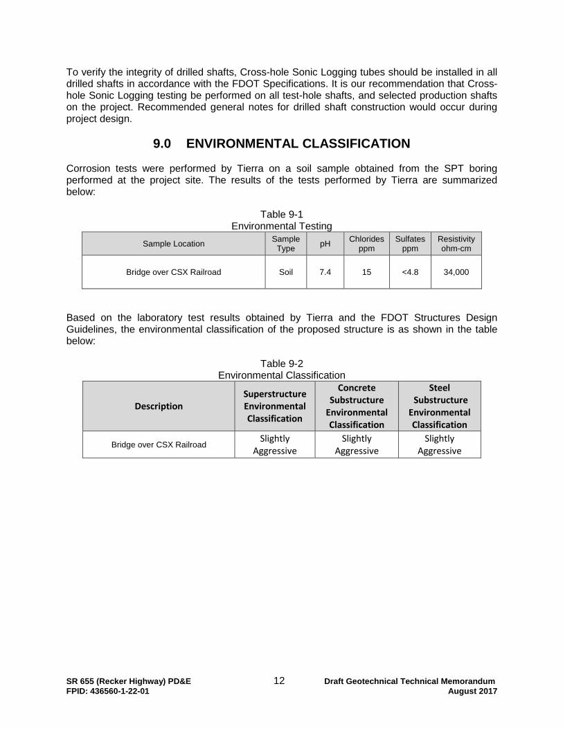
9.0 ENVIRONMENTAL CLASSIFICATION Corrosion tests were performed by Tierra on a soil sample obtained from the SPT boring performed at the project site. The results of the tests performed by Tierra are summarized below:
Table 9-1 Environmental Testing
Sample Location Sample Type pH Chlorides
ppm Sulfates
ppm Resistivity ohm-cm
Bridge over CSX Railroad Soil 7.4 15 <4.8 34,000
Based on the laboratory test results obtained by Tierra and the FDOT Structures Design Guidelines, the environmental classification of the proposed structure is as shown in the table below:
Table 9-2 Environmental Classification
Description Superstructure Environmental Classification
Concrete Substructure
Environmental Classification
Steel Substructure
Environmental Classification
Bridge over CSX Railroad Slightly Aggressive
Slightly Aggressive
Slightly Aggressive

SR 655 (Recker Highway) PD&E 13 Draft Geotechnical Technical Memorandum FPID: 436560-1-22-01 August 2017
10.0 REPORT LIMITATIONS Our services have been performed, our findings obtained, and our recommendations prepared in accordance with generally accepted Geotechnical engineering principles and practices. This company is not responsible for the conclusions, opinions, or recommendations made by others based on this data.
The scope of the investigation was intended to provide a preliminary evaluation of the soil conditions within the influence zone of the proposed overpass foundations to support the project PD&E study. The analyses and recommendations submitted in this report are based upon the data obtained from the soil boring performed at the location indicated. If any subsoil variations become evident during the course of this project, a re-evaluation of the recommendations contained in this report will be necessary after we have had an opportunity to observe the characteristics of the conditions encountered. The applicability of the report should also be reviewed in the event significant changes occur in the design, nature or location of the proposed improvements.
The scope of our services does not include any environmental assessment or investigation for the presence or absence of hazardous or toxic materials in the soil, groundwater, or surface water within or beyond the site studied. Any statements in this report regarding odors, staining of soils, or other unusual conditions observed are strictly for the information of Volkert, Inc. and the FDOT.

APPENDIX A
USDA Soil Survey Map & USGS Topographic Map (1 Sheet)
Report of Core Borings (1 Sheet)

99
635816
31
16
1699
58
15
59
61
63
751
13
31
63
17
26
6/7/2016swebb J:\6511\2015 Files\6511-15-080 Recker Hwy Volkert\Microstation\USDA_USGS01.dgn8:01:41 AM
436560-1-22-01 POLK SR 655
ROAD NO. FINANCIAL PROJECT IDCOUNTY
DATE DESCRIPTION
REVISIONS
DATE DESCRIPTIONNO.
SHEETSTATE OF FLORIDA
DEPARTMENT OF TRANSPORTATION
USGS QUADRANGLE MAP
USDA SOIL SURVEY MAP &
N
0 100 800
Feet
US 92
TH
UR
NHILL
RD.
US 92
TH
UR
NHILL
RD.
TH
UR
NHILL
RD.
REFERENCE: USGS QUADRANGLE MAP OF "AUBURNDALE, FLORIDA"REFERENCE: USDA SOIL SURVEY OF POLK COUNTY, FLORIDA
CSX RAILR
OAD
CSX RAILR
OAD
LAWRENCE P. MOORE, P.E.
P.E. LICENSE NUMBER 47673
TIERRA, INC.
7351 TEMPLE TERRACE HIGHWAY
TAMPA, FLORIDA 33637
CERTIFICATE OF AUTHORIZATION NO. 6486
SECTION:
RANGE:
TOWNSHIP:
9, 15 & 16
25E
28S
IMPROVEMENTS
RECKER HIGHWAY
APPROXIMATE END
IMPROVEMENTS
RECKER HIGHWAY
APPROXIMATE START
IMPROVEMENTS
THORNHILL ROAD
APPROXIMATE START
IMPROVEMENTS
THORNHILL ROAD
APPROXIMATE START
IMPROVEMENTS
RECKER HIGHWAY
APPROXIMATE START
IMPROVEMENTS
RECKER HIGHWAY
APPROXIMATE END

115
BORING LOCATION PLAN
N
Feet
100200
APPROXIMATE SPT BORING LOCATION
LEGEND
12 to 24
6 to 12
24 to 40
8 to 24
(BLOWS/FT.)
(BLOWS/FT.)
GREATER THAN 24
LESS THAN 3
GREATER THAN 40
LESS THAN 1
3 to 6
1 to 3
3 to 8
8 to 15
30 to 50
10 to 30
4 to 10
(BLOWS/FT.)SPT N-VALUE
(BLOWS/FT.)
GREATER THAN 30
LESS THAN 4
GREATER THAN 50
LESS THAN 2
VERY LOOSE
HARD
VERY STIFF
STIFF
SILTS AND CLAYS
CONSISTENCY
FIRM
SOFT
VERY SOFT
LOOSE
DENSE
VERY DENSE
4 to 8
2 to 4
RELATIVE DENSITY
GRANULAR MATERIALS-
SAFETY HAMMER
MEDIUM DENSE
AUTOMATIC HAMMER
SPT N-VALUE
SPT N-VALUE SPT N-VALUE
15 to 30
GRAY TO BROWN SAND TO SAND WITH SILT (SP/SP-SM)
GRAY SILTY SAND (SM)
LIGHT GRAY TO BROWN CLAYEY SAND (SC)
GRAY TO GREEN SILT TO CLAY (MH/CH)
BOR # BB-1
116+31
40' LT.
ELEV. 149.0
DATE 4/6/2016
DRILLER I. POORAN
HAMMER AUTOMATIC
RIG D-25
LAWRENCE P. MOORE, P.E.
P.E. LICENSE NUMBER 47673
TIERRA, INC.
7351 TEMPLE TERRACE HIGHWAY
TAMPA, FLORIDA 33637
CERTIFICATE OF AUTHORIZATION NO. 6486
BJS
DRR
BJS
LPM
SUPERSTRUCTURE SLIGHTLY AGGRESSIVE
SOIL TEST RESULTS:
RESISTIVITY
CHLORIDES
SULFATES
pH
ENVIRONMENTAL CLASSIFICATION:
SUBSTRUCTURE CONCRETE: SLIGHTLY AGGRESSIVE
SUBSTRUCTURE STEEL: SLIGHTLY AGGRESSIVE
34,000 OHM-CM
15 PPM
<4.8 PPM
7.4
NOTES:BB-1
GNA
THE INTRODUCTION OF DRILLING FLUID.
GROUNDWATER NOT APPARENT DUE TO
OFF.
REF.
STA.
ACCESS ROAD
2.
1.
TH
E
OF
FI
CI
AL
RE
CO
RD
OF
THI
S
SH
EE
T I
S
TH
E
EL
EC
TR
ONI
C
FI
LE
DI
GI
TA
LL
Y
SI
GN
ED
AN
D
SE
AL
ED
UN
DE
R
RU
LE 61
G15-23.004,
F.
A.
C.
ADDITIONAL COST TO THE DEPARTMENT.
ELEVATION OF UP TO +120 FEET, NGVD, AT NO
TO HANDLE A POTENTIOMETRIC SURFACE
CONSTRUCTION METHODS SHOULD BE PREPARED
APPROXIMATELY +120 FEET, NGVD. TOOLS AND
PROPOSED BRIDGE LOCATION IS ON THE ORDER OF
POTENTIOMETRIC SURFACE ELEVATION AT THE
FLORIDA”MAPS PUBLISHED BY THE USGS, THESURFACE OF THE UPPER FLORIDAN AQUIFER IN
BASED ON A REVIEW OF THE “POTENTIOMETRIC
PROVIDED BY VOLKERT.
EVALUATED USING MICROSTATION DESIGN FILES
THE TWO ROADWAY ALIGNMENTS CURRENTLY BEING
WERE CONVERTED TO STATION AND OFFSET FOR
AND ELEVATION. THE STATE PLANE COORDINATES
PROJECT SURVEYOR FOR STATE PLANE COORDINATES
THE BORING LOCATION WAS SURVEYED BY THE
NORTH AMERICAN VERTICAL DATUM OF 1988
NATIONAL GEODETIC VERTICAL DATUM OF 1929
PLASTICITY INDEX (%)
LIQUID LIMIT (%)
NATURAL MOISTURE CONTENT (%)
PERCENT PASSING #200 SIEVE
HAND AUGERED TO VERIFY UTILITY CLEARANCE
NUMBER OF BLOWS FOR 4 INCHES OF PENETRATION
(UNLESS OTHERWISE NOTED).
SPT VALUE FOR 12 INCHES OF PENETRATION
NUMBERS TO THE LEFT OF BORINGS INDICATE
FOR CONFIRMATION OF VISUAL REVIEW.
AND LABORATORY TESTING ON SELECTED SAMPLES
GROUP SYMBOL AS DETERMINED BY VISUAL REVIEW
UNIFIED SOIL CLASSIFICATION SYSTEM (ASTM D 2487)
NAVD
NGVD
PI
LL
NMC
-200
HA
50/4
N
SP
150
145
140
135
130
125
120
115
110
105
100
95
90
85
80
75
70
65
ELE
VA
TIO
N IN F
EE
T (N
AV
D)
GNAN
HA
HA
HA
7
6
18
16
12
13
42
10
5
21
50/3
50/4
50/6
50/1
50/5
50/6
50/3
150
145
140
135
130
125
120
115
110
105
100
95
90
85
80
75
70
65
ELE
VA
TIO
N IN F
EE
T (N
AV
D)
GRAY SILTY SAND (SM)
LIGHT GRAY TO BROWN CLAYEY SAND (SC)
GRAY TO GREEN SILT TO CLAY (MH/CH)
GRAY SILTY SAND (SM)
LIGHT GRAY TO BROWN CLAYEY SAND (SC)
LIGHT GRAY TO BROWN CLAYEY SAND (SC)
LIGHT GRAY TO BROWN CLAYEY SAND (SC)
GRAY TO GREEN SILT TO CLAY (MH/CH)
SILT (SP/SP-SM)
GRAY TO BROWN SAND TO SAND WITH
SILT (SP/SP-SM)
GRAY TO BROWN SAND TO SAND WITH
-200=8
-200=24
PI=24
LL=39
NMC=21
-200=34
PI=19
LL=42
NMC=32
-200=23
PI=29
LL=75
NMC=46
-200=79
PI=15
LL=78
NMC=64
-200=27
PI=37
LL=76
NMC=47
-200=31
PI=35
LL=80
NMC=46
-200=26
ELEVATION 64.0 FT (NAVD)
BORING TERMINATED ATLONGITUDE: W 81.81352
LATITUDE: N 28.0547360 60
C/L CONST.
CL CONST.
REF. DWG. NO.
SHEET NO.
SHEET TITLE:
PROJECT NAME:
DRAWN BY:
CHECKED BY:
DESIGNED BY:
CHECKED BY:
ROAD NO. COUNTY FINANCIAL PROJECT ID
REVISIONS
DATE BY DESCRIPTION DATE BY DESCRIPTION
SR 655 POLK 436560-1-22-01
REPORT OF CORE BORINGS
bsawaska 8/7/2017 4:18:50 PM J:\6511\2015 Files\6511-15-080 Recker Hwy Volkert\Microstation\B1Boring01.dgn
DEPARTMENT OF TRANSPORTATION
STATE OF FLORIDA
OVER CSX RAILROAD
SR 655 (RECKER HIGHWAY) GRADE SEPARATION

APPENDIX B
Axial Capacity Curves (3 Sheets)
FB-Deep Output Files (24 Sheets)

DRAWN BY: SCALE: PROJECT NO.
DRR Noted 6511-15-080CHECKED BY: DATE:
EMF May 2016
Recker Highway Grade Separation over CSXBridge over CSX Railroad
FPID: 436560-1-22-01
Boring BB-118-Inch and 24-Inch PSC Pile
Polk County, Florida
70
80
90
100
110
120
130
140
150
0 50 100 150 200 250 300 350 400 450 500 550 600 650
Pile
Tip
Ele
vatio
n (fe
et, N
GVD
)
Nominal Bearing Resistance (tons)
18-Inch PSC Pile 24-Inch PSC Pile

DRAWN BY: SCALE: PROJECT NO.
DRR Noted 6511-15-080CHECKED BY: DATE:
EMF May 2016
Recker Highway Grade Separation over CSX
Boring BB-1
Bridge over CSX RailroadPolk County, FloridaFPID: 436560-1-22-01
14x89 H-Pile
70
80
90
100
110
120
130
140
150
0 50 100 150 200 250
Pile
Tip
Ele
vatio
n (fe
et, N
GVD
)
Nominal Bearing Resistance (tons)
14x89 H-Pile

DRAWN BY: SCALE: PROJECT NO.
DRR Noted 6511-15-080CHECKED BY: DATE:
EMF May 2016
Bridge over CSX RailroadPolk County, FloridaFPID: 436560-1-22-01
20-Inch and 24-Inch Pipe Pile (Thickness = 0.5-inches)
Recker Highway Grade Separation over CSX
Boring BB-1
70
80
90
100
110
120
130
140
150
0 50 100 150 200 250 300 350 400
Pile
Tip
Ele
vatio
n (fe
et, N
GVD
)
Nominal Bearing Resistance (tons)
20-Inch Pipe Pile (Thickness = 0.5-inches) 24-Inch Pipe Pile (Thickness = 0.5-inches)

BB-1 PSCFlorida Bridge Software Institute Date: May 09, 2016Shaft and Pile Analysis (FB-Deep v.2.04) Time: 11:46:19_________________________________________________________________________________
General Information:==================== Input file: .....2015 Files\6511-15-080 Recker Hwy Volkert\FB Deep\BB-1 PSC.spc Project number: 436560-1-22-01 Job name: Recker Highway Engineer: Daniel Ruel Units: English
Analysis Information:=====================Analysis Type: SPT
Soil Information:================= Boring date: 4/6/2016, Boring Number: BB-1 Station number: 116+35/116+31 Offset: 13' LT/40' LT
Ground Elevation: 150.100(ft)
Hammer type: Safety Hammer
ID Depth No. of Blows Soil Type (ft) (Blows/ft) ----- ------------ ------------- ------------------------------- 1 0.00 0.00 3- Clean sand 2 2.00 4.00 3- Clean sand 3 4.00 4.00 3- Clean sand 4 6.00 4.00 3- Clean sand 5 8.00 7.00 3- Clean sand 6 10.00 6.00 2- Clay and silty sand 7 15.00 18.00 2- Clay and silty sand 8 20.00 16.00 2- Clay and silty sand 9 25.00 12.00 3- Clean sand 10 30.00 13.00 3- Clean sand 11 35.00 42.00 3- Clean sand 12 40.00 10.00 3- Clean sand 13 45.00 5.00 2- Clay and silty sand 14 50.00 21.00 2- Clay and silty sand 15 55.00 100.00 1- Plastic Clay 16 60.00 100.00 1- Plastic Clay 17 65.00 100.00 2- Clay and silty sand 18 70.00 100.00 1- Plastic Clay 19 75.00 100.00 1- Plastic Clay 20 80.00 100.00 2- Clay and silty sand 21 85.00 100.00 2- Clay and silty sand 22 90.00 100.00 2- Clay and silty sand 23 95.00 100.00 2- Clay and silty sand
Blowcount Average Per Soil Layer ----------------------------------
Layer Starting Bottom Thickness Average Soil Type Num. Elevation Elevation Blowcount (ft) (ft) (ft) (Blows/ft)
Page 1
BB-1 PSC----- ---------- ---------- ---------- ------------- --------------------------------- 1 150.10 140.10 10.00 3.80 3-Clean Sand 2 140.10 125.10 15.00 13.33 2-Clay and Silty Sand 3 125.10 105.10 20.00 19.25 3-Clean Sand 4 105.10 95.10 10.00 13.00 2-Clay and Silty Sand 5 95.10 85.10 10.00 100.00 1-Plastic Clay 6 85.10 80.10 5.00 100.00 2-Clay and Silty Sand 7 80.10 70.10 10.00 100.00 1-Plastic Clay 8 70.10 55.10 15.00 100.00 2-Clay and Silty Sand
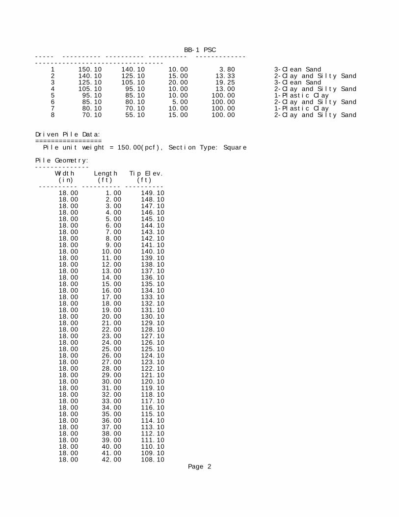
Driven Pile Data:================= Pile unit weight = 150.00(pcf), Section Type: Square
Pile Geometry:-------------- Width Length Tip Elev. (in) (ft) (ft) ---------- ---------- ---------- 18.00 1.00 149.10 18.00 2.00 148.10 18.00 3.00 147.10 18.00 4.00 146.10 18.00 5.00 145.10 18.00 6.00 144.10 18.00 7.00 143.10 18.00 8.00 142.10 18.00 9.00 141.10 18.00 10.00 140.10 18.00 11.00 139.10 18.00 12.00 138.10 18.00 13.00 137.10 18.00 14.00 136.10 18.00 15.00 135.10 18.00 16.00 134.10 18.00 17.00 133.10 18.00 18.00 132.10 18.00 19.00 131.10 18.00 20.00 130.10 18.00 21.00 129.10 18.00 22.00 128.10 18.00 23.00 127.10 18.00 24.00 126.10 18.00 25.00 125.10 18.00 26.00 124.10 18.00 27.00 123.10 18.00 28.00 122.10 18.00 29.00 121.10 18.00 30.00 120.10 18.00 31.00 119.10 18.00 32.00 118.10 18.00 33.00 117.10 18.00 34.00 116.10 18.00 35.00 115.10 18.00 36.00 114.10 18.00 37.00 113.10 18.00 38.00 112.10 18.00 39.00 111.10 18.00 40.00 110.10 18.00 41.00 109.10 18.00 42.00 108.10
Page 2

BB-1 PSC 18.00 43.00 107.10 18.00 44.00 106.10 18.00 45.00 105.10 18.00 46.00 104.10 18.00 47.00 103.10 18.00 48.00 102.10 18.00 49.00 101.10 18.00 50.00 100.10 18.00 51.00 99.10 18.00 52.00 98.10 18.00 53.00 97.10 18.00 54.00 96.10 18.00 55.00 95.10 18.00 56.00 94.10 18.00 57.00 93.10 18.00 58.00 92.10 18.00 59.00 91.10 18.00 60.00 90.10 18.00 61.00 89.10 18.00 62.00 88.10 18.00 63.00 87.10 18.00 64.00 86.10 18.00 65.00 85.10 18.00 66.00 84.10 18.00 67.00 83.10 18.00 68.00 82.10 18.00 69.00 81.10 18.00 70.00 80.10 18.00 71.00 79.10 18.00 72.00 78.10 18.00 73.00 77.10 18.00 74.00 76.10 18.00 75.00 75.10 18.00 76.00 74.10 18.00 77.00 73.10 18.00 78.00 72.10 18.00 79.00 71.10 18.00 80.00 70.10 18.00 81.00 69.10 18.00 82.00 68.10 18.00 83.00 67.10 18.00 84.00 66.10 18.00 85.00 65.10 24.00 1.00 149.10 24.00 2.00 148.10 24.00 3.00 147.10 24.00 4.00 146.10 24.00 5.00 145.10 24.00 6.00 144.10 24.00 7.00 143.10 24.00 8.00 142.10 24.00 9.00 141.10 24.00 10.00 140.10 24.00 11.00 139.10 24.00 12.00 138.10 24.00 13.00 137.10 24.00 14.00 136.10 24.00 15.00 135.10 24.00 16.00 134.10 24.00 17.00 133.10 24.00 18.00 132.10 24.00 19.00 131.10 24.00 20.00 130.10
Page 3

BB-1 PSC 24.00 21.00 129.10 24.00 22.00 128.10 24.00 23.00 127.10 24.00 24.00 126.10 24.00 25.00 125.10 24.00 26.00 124.10 24.00 27.00 123.10 24.00 28.00 122.10 24.00 29.00 121.10 24.00 30.00 120.10 24.00 31.00 119.10 24.00 32.00 118.10 24.00 33.00 117.10 24.00 34.00 116.10 24.00 35.00 115.10 24.00 36.00 114.10 24.00 37.00 113.10 24.00 38.00 112.10 24.00 39.00 111.10 24.00 40.00 110.10 24.00 41.00 109.10 24.00 42.00 108.10 24.00 43.00 107.10 24.00 44.00 106.10 24.00 45.00 105.10 24.00 46.00 104.10 24.00 47.00 103.10 24.00 48.00 102.10 24.00 49.00 101.10 24.00 50.00 100.10 24.00 51.00 99.10 24.00 52.00 98.10 24.00 53.00 97.10 24.00 54.00 96.10 24.00 55.00 95.10 24.00 56.00 94.10 24.00 57.00 93.10 24.00 58.00 92.10 24.00 59.00 91.10 24.00 60.00 90.10 24.00 61.00 89.10 24.00 62.00 88.10 24.00 63.00 87.10 24.00 64.00 86.10 24.00 65.00 85.10 24.00 66.00 84.10 24.00 67.00 83.10 24.00 68.00 82.10 24.00 69.00 81.10 24.00 70.00 80.10 24.00 71.00 79.10 24.00 72.00 78.10 24.00 73.00 77.10 24.00 74.00 76.10 24.00 75.00 75.10 24.00 76.00 74.10 24.00 77.00 73.10 24.00 78.00 72.10 24.00 79.00 71.10 24.00 80.00 70.10 24.00 81.00 69.10 24.00 82.00 68.10 24.00 83.00 67.10
Page 4

BB-1 PSC 24.00 84.00 66.10 24.00 85.00 65.10
Driven Pile Capacity:=====================
Section Type: Square Pile Width: 18.00 (in)
Test Pile Ultimate Mobilized Estimated Allowable Ultimate Pile Width Side End Davisson Pile Pile Length Friction Bearing Capacity Capacity Capacity (ft) (in) (tons) (tons) (tons) (tons) (tons) ----- ------ ---------- ---------- ---------- ---------- ---------- 1.00 18.0 0.00 0.00 0.00 0.00 0.01 2.00 18.0 0.00 0.14 0.14 0.07 0.42 3.00 18.0 0.00 0.66 0.66 0.33 1.99 4.00 18.0 0.00 1.44 1.44 0.72 4.32 5.00 18.0 0.00 2.26 2.26 1.13 6.78 6.00 18.0 0.00 3.30 3.30 1.65 9.91 7.00 18.0 0.08 4.68 4.76 2.38 14.13 8.00 18.0 0.35 6.23 6.59 3.29 19.06 9.00 18.0 0.90 8.04 8.94 4.47 25.02 10.00 18.0 3.23 9.41 12.64 6.32 31.46 11.00 18.0 4.91 9.64 14.55 7.28 33.84 12.00 18.0 6.80 10.27 17.07 8.53 37.61 13.00 18.0 9.00 11.28 20.28 10.14 42.84 14.00 18.0 11.68 12.54 24.22 12.11 49.31 15.00 18.0 14.95 13.97 28.92 14.46 56.85 16.00 18.0 18.60 15.70 34.30 17.15 65.70 17.00 18.0 22.64 16.73 39.37 19.69 72.83 18.00 18.0 26.66 17.97 44.63 22.31 80.56 19.00 18.0 30.64 19.24 49.88 24.94 88.35 20.00 18.0 34.56 20.37 54.92 27.46 95.66 21.00 18.0 38.23 21.46 59.69 29.84 102.61 22.00 18.0 41.43 22.70 64.14 32.07 109.54 23.00 18.0 44.17 23.93 68.09 34.05 115.95 24.00 18.0 46.42 24.97 71.39 35.70 121.34 25.00 18.0 52.10 25.88 77.98 38.99 129.74 26.00 18.0 53.40 26.01 79.40 39.70 131.42 27.00 18.0 54.50 26.56 81.05 40.53 134.16 28.00 18.0 55.37 27.81 83.18 41.59 138.80 29.00 18.0 56.06 30.06 86.12 43.06 146.25 30.00 18.0 56.64 33.58 90.22 45.11 157.38 31.00 18.0 57.53 37.62 95.15 47.58 170.40 32.00 18.0 58.98 41.36 100.35 50.17 183.08 33.00 18.0 61.06 44.29 105.35 52.68 193.93 34.00 18.0 63.88 45.86 109.75 54.87 201.47 35.00 18.0 67.62 45.61 113.23 56.62 204.45 36.00 18.0 71.81 44.29 116.10 58.05 204.68 37.00 18.0 75.76 42.73 118.49 59.24 203.94 38.00 18.0 79.34 41.04 120.38 60.19 202.46 39.00 18.0 82.02 38.87 120.89 60.45 198.64 40.00 18.0 83.69 36.61 120.30 60.15 193.51 41.00 18.0 85.06 34.99 120.05 60.03 190.04 42.00 18.0 86.44 33.92 120.36 60.18 188.20 43.00 18.0 87.84 33.10 120.95 60.47 187.15
Page 5

BB-1 PSC 44.00 18.0 89.27 32.26 121.54 60.77 186.07 45.00 18.0 96.01 16.06 112.07 56.04 144.20 46.00 18.0 97.73 13.73 111.46 55.73 138.92 47.00 18.0 100.14 16.10 116.24 58.12 148.45 48.00 18.0 102.61 17.22 119.83 59.92 154.28 49.00 18.0 105.58 18.92 124.49 62.25 162.32 50.00 18.0 109.20 21.05 130.25 65.12 172.35 51.00 18.0 113.68 23.44 137.12 68.56 184.01 52.00 18.0 119.45 24.56 144.01 72.00 193.13 53.00 18.0 126.02 25.46 151.49 75.74 202.42 54.00 18.0 133.41 26.18 159.60 79.80 211.96 55.00 18.0 146.37 25.73 172.10 86.05 223.57 56.00 18.0 154.97 26.20 181.17 90.59 233.58 57.00 18.0 162.82 28.23 191.05 95.53 247.52 58.00 18.0 170.49 32.59 203.08 101.54 268.26 59.00 18.0 179.48 36.30 215.78 107.89 288.39 60.00 18.0 188.46 40.58 229.05 114.52 310.21 61.00 18.0 197.34 44.15 241.49 120.74 329.78 62.00 18.0 206.00 46.34 252.35 126.17 345.04 63.00 18.0 214.44 47.23 261.67 130.84 356.14 64.00 18.0 222.66 46.86 269.52 134.76 363.24 65.00 18.0 233.40 45.26 278.66 139.33 369.17 66.00 18.0 241.37 43.38 284.75 142.38 371.52 67.00 18.0 249.56 41.89 291.45 145.73 375.23 68.00 18.0 257.98 40.81 298.79 149.39 380.40 69.00 18.0 266.63 40.15 306.78 153.39 387.09 70.00 18.0 275.50 31.55 307.05 153.52 370.14 71.00 18.0 284.36 31.73 316.09 158.04 379.55 72.00 18.0 292.79 32.82 325.61 162.80 391.24 73.00 18.0 300.93 35.57 336.50 168.25 407.65 74.00 18.0 309.91 38.47 348.38 174.19 425.32 75.00 18.0 318.90 42.11 361.01 180.50 445.22 76.00 18.0 327.78 45.92 373.69 186.85 465.52 77.00 18.0 336.43 49.44 385.86 192.93 484.74 78.00 18.0 344.86 52.49 397.34 198.67 502.32 79.00 18.0 353.07 54.96 408.03 204.02 517.96 80.00 18.0 362.52 56.64 419.17 209.58 532.46 81.00 18.0 370.23 56.84 427.07 213.54 540.75 82.00 18.0 377.64 57.54 435.18 217.59 550.27 83.00 18.0 384.82 58.84 443.66 221.83 561.33 84.00 18.0 391.91 60.69 452.61 226.30 574.00 85.00 18.0 399.04 63.11 462.15 231.07 588.37
Section Type: Square Pile Width: 24.00 (in)
Test Pile Ultimate Mobilized Estimated Allowable Ultimate Pile Width Side End Davisson Pile Pile Length Friction Bearing Capacity Capacity Capacity (ft) (in) (tons) (tons) (tons) (tons) (tons) ----- ------ ---------- ---------- ---------- ---------- ---------- 1.00 24.0 0.00 1.16 1.16 0.58 3.47 2.00 24.0 0.00 1.55 1.55 0.77 4.65 3.00 24.0 0.00 2.10 2.10 1.05 6.29 4.00 24.0 0.00 2.80 2.80 1.40 8.41 5.00 24.0 0.00 3.85 3.85 1.92 11.54 6.00 24.0 0.00 5.32 5.32 2.66 15.95 7.00 24.0 0.09 7.31 7.40 3.70 22.01 8.00 24.0 0.41 9.73 10.14 5.07 29.59 9.00 24.0 1.00 12.38 13.39 6.69 38.15
Page 6

BB-1 PSC 10.00 24.0 4.31 18.13 22.44 11.22 58.71 11.00 24.0 6.62 18.37 24.99 12.49 61.72 12.00 24.0 9.29 19.00 28.29 14.14 66.28 13.00 24.0 12.44 19.91 32.35 16.17 72.16 14.00 24.0 16.15 21.04 37.19 18.59 79.28 15.00 24.0 20.45 22.43 42.87 21.44 87.72 16.00 24.0 25.04 24.11 49.15 24.58 97.38 17.00 24.0 29.40 26.68 56.08 28.04 109.45 18.00 24.0 33.81 29.98 63.79 31.89 123.75 19.00 24.0 39.07 32.25 71.32 35.66 135.81 20.00 24.0 44.28 34.61 78.89 39.44 148.10 21.00 24.0 49.16 36.98 86.14 43.07 160.09 22.00 24.0 53.46 39.27 92.73 46.36 171.27 23.00 24.0 57.14 41.25 98.39 49.20 180.90 24.00 24.0 60.19 43.55 103.74 51.87 190.83 25.00 24.0 69.47 47.37 116.84 58.42 211.59 26.00 24.0 71.11 47.69 118.81 59.40 214.20 27.00 24.0 72.41 48.85 121.26 60.63 218.97 28.00 24.0 73.42 51.12 124.54 62.27 226.78 29.00 24.0 74.34 54.33 128.67 64.34 237.34 30.00 24.0 75.33 57.93 133.26 66.63 249.13 31.00 24.0 76.71 61.41 138.12 69.06 260.93 32.00 24.0 78.84 64.16 143.00 71.50 271.32 33.00 24.0 81.84 65.73 147.57 73.79 279.04 34.00 24.0 85.85 66.02 151.86 75.93 283.90 35.00 24.0 91.04 65.06 156.11 78.05 286.23 36.00 24.0 96.83 63.27 160.10 80.05 286.64 37.00 24.0 102.31 61.23 163.54 81.77 286.00 38.00 24.0 107.32 59.00 166.32 83.16 284.31 39.00 24.0 111.52 57.02 168.54 84.27 282.58 40.00 24.0 114.45 55.87 170.32 85.16 282.06 41.00 24.0 116.57 55.41 171.99 85.99 282.81 42.00 24.0 118.48 55.47 173.95 86.98 284.89 43.00 24.0 120.16 56.19 176.35 88.17 288.72 44.00 24.0 121.99 56.99 178.98 89.49 292.96 45.00 24.0 128.01 33.25 161.26 80.63 227.76 46.00 24.0 130.31 26.26 156.57 78.29 209.09 47.00 24.0 133.55 30.23 163.79 81.89 224.25 48.00 24.0 137.59 33.49 171.07 85.54 238.04 49.00 24.0 141.69 35.18 176.87 88.44 247.24 50.00 24.0 146.52 37.39 183.91 91.95 258.68 51.00 24.0 152.30 39.89 192.19 96.09 271.97 52.00 24.0 159.20 42.57 201.78 100.89 286.92 53.00 24.0 167.32 45.38 212.70 106.35 303.45 54.00 24.0 177.11 47.09 224.20 112.10 318.38 55.00 24.0 195.17 48.19 243.36 121.68 339.74 56.00 24.0 206.62 48.83 255.45 127.72 353.11 57.00 24.0 216.94 51.53 268.47 134.24 371.53 58.00 24.0 226.62 57.21 283.83 141.92 398.25 59.00 24.0 236.69 65.76 302.45 151.22 433.97 60.00 24.0 248.67 70.48 319.14 159.57 460.10 61.00 24.0 260.51 74.08 334.59 167.29 482.74 62.00 24.0 272.07 76.06 348.13 174.07 500.25 63.00 24.0 283.34 76.23 359.57 179.78 512.02 64.00 24.0 294.32 75.08 369.40 184.70 519.57 65.00 24.0 311.20 73.15 384.35 192.18 530.65 66.00 24.0 321.82 71.00 392.83 196.41 534.83 67.00 24.0 332.75 69.29 402.04 201.02 540.63 68.00 24.0 343.97 68.09 412.07 206.03 548.25 69.00 24.0 355.50 67.91 423.42 211.71 559.24 70.00 24.0 367.33 60.11 427.45 213.72 547.68 71.00 24.0 379.22 60.24 439.47 219.73 559.95 72.00 24.0 390.14 62.17 452.31 226.16 576.66
Page 7

BB-1 PSC 73.00 24.0 400.42 66.67 467.09 233.55 600.44 74.00 24.0 410.76 74.00 484.76 242.38 632.76 75.00 24.0 422.74 79.14 501.88 250.94 660.17 76.00 24.0 434.58 84.37 518.95 259.47 687.69 77.00 24.0 446.13 89.43 535.56 267.78 714.41 78.00 24.0 457.39 93.99 551.38 275.69 739.36 79.00 24.0 468.35 97.89 566.23 283.12 762.00 80.00 24.0 483.37 105.28 588.64 294.32 799.19 81.00 24.0 493.82 105.30 599.12 299.56 809.73 82.00 24.0 504.23 105.39 609.62 304.81 820.40 83.00 24.0 514.51 105.70 620.21 310.11 831.61 84.00 24.0 524.60 106.40 631.00 315.50 843.80 85.00 24.0 534.47 107.67 642.13 321.07 857.46
NOTES ------- 1. MOBILIZED END BEARING IS 1/3 OF THE ORIGINAL RB-121 VALUES.
2. DAVISSON PILE CAPACITY IS AN ESTIMATE BASED ON FAILURE CRITERIA, AND EQUALS ULTIMATE SIDE FRICTION PLUS MOBILIZED END BEARING.
3. ALLOWABLE PILE CAPACITY IS 1/2 THE DAVISSON PILE CAPACITY.
4. ULTIMATE PILE CAPACITY IS ULTIMATE SIDE FRICTION PLUS 3 x THE MOBILIZED END BEARING. EXCEPTION: FOR H-PILES TIPPED IN SAND OR LIMESTONE, THE ULTIMATE PILE CAPACITY IS ULTIMATE SIDE FRICTION PLUS 2 x THE MOBILIZED END BEARING.
Page 8

BB-1 Pipe PileFlorida Bridge Software Institute Date: May 09, 2016Shaft and Pile Analysis (FB-Deep v.2.04) Time: 11:48:47_________________________________________________________________________________
General Information:==================== Input file: .....iles\6511-15-080 Recker Hwy Volkert\FB Deep\BB-1 Pipe Pile.spc Project number: 436560-1-22-01 Job name: Recker Highway Engineer: Daniel Ruel Units: English
Analysis Information:=====================Analysis Type: SPT
Soil Information:================= Boring date: 4/6/2016, Boring Number: BB-1 Station number: 116+35/116+31 Offset: 13' LT/40' LT
Ground Elevation: 150.100(ft)
Hammer type: Safety Hammer
ID Depth No. of Blows Soil Type (ft) (Blows/ft) ----- ------------ ------------- ------------------------------- 1 0.00 0.00 3- Clean sand 2 2.00 4.00 3- Clean sand 3 4.00 4.00 3- Clean sand 4 6.00 4.00 3- Clean sand 5 8.00 7.00 3- Clean sand 6 10.00 6.00 2- Clay and silty sand 7 15.00 18.00 2- Clay and silty sand 8 20.00 16.00 2- Clay and silty sand 9 25.00 12.00 3- Clean sand 10 30.00 13.00 3- Clean sand 11 35.00 42.00 3- Clean sand 12 40.00 10.00 3- Clean sand 13 45.00 5.00 2- Clay and silty sand 14 50.00 21.00 2- Clay and silty sand 15 55.00 100.00 1- Plastic Clay 16 60.00 100.00 1- Plastic Clay 17 65.00 100.00 2- Clay and silty sand 18 70.00 100.00 1- Plastic Clay 19 75.00 100.00 1- Plastic Clay 20 80.00 100.00 2- Clay and silty sand 21 85.00 100.00 2- Clay and silty sand 22 90.00 100.00 2- Clay and silty sand 23 95.00 100.00 2- Clay and silty sand
Blowcount Average Per Soil Layer ----------------------------------
Layer Starting Bottom Thickness Average Soil Type Num. Elevation Elevation Blowcount (ft) (ft) (ft) (Blows/ft)
Page 1

BB-1 Pipe Pile----- ---------- ---------- ---------- ------------- --------------------------------- 1 150.10 140.10 10.00 3.80 3-Clean Sand 2 140.10 125.10 15.00 13.33 2-Clay and Silty Sand 3 125.10 105.10 20.00 19.25 3-Clean Sand 4 105.10 95.10 10.00 13.00 2-Clay and Silty Sand 5 95.10 85.10 10.00 100.00 1-Plastic Clay 6 85.10 80.10 5.00 100.00 2-Clay and Silty Sand 7 80.10 70.10 10.00 100.00 1-Plastic Clay 8 70.10 55.10 15.00 100.00 2-Clay and Silty Sand
Driven Pile Data:================= Pile unit weight = 490.00(pcf), Section Type: Pipe
Pile Geometry:-------------- Width Length Tip Elev. Thickness Pile End (in) (ft) (ft) (in) ---------- ---------- ---------- ---------- ---------- 20.00 1.00 149.10 0.50 OPEN 20.00 2.00 148.10 0.50 OPEN 20.00 3.00 147.10 0.50 OPEN 20.00 4.00 146.10 0.50 OPEN 20.00 5.00 145.10 0.50 OPEN 20.00 6.00 144.10 0.50 OPEN 20.00 7.00 143.10 0.50 OPEN 20.00 8.00 142.10 0.50 OPEN 20.00 9.00 141.10 0.50 OPEN 20.00 10.00 140.10 0.50 OPEN 20.00 11.00 139.10 0.50 OPEN 20.00 12.00 138.10 0.50 OPEN 20.00 13.00 137.10 0.50 OPEN 20.00 14.00 136.10 0.50 OPEN 20.00 15.00 135.10 0.50 OPEN 20.00 16.00 134.10 0.50 OPEN 20.00 17.00 133.10 0.50 OPEN 20.00 18.00 132.10 0.50 OPEN 20.00 19.00 131.10 0.50 OPEN 20.00 20.00 130.10 0.50 OPEN 20.00 21.00 129.10 0.50 OPEN 20.00 22.00 128.10 0.50 OPEN 20.00 23.00 127.10 0.50 OPEN 20.00 24.00 126.10 0.50 OPEN 20.00 25.00 125.10 0.50 OPEN 20.00 26.00 124.10 0.50 OPEN 20.00 27.00 123.10 0.50 OPEN 20.00 28.00 122.10 0.50 OPEN 20.00 29.00 121.10 0.50 OPEN 20.00 30.00 120.10 0.50 OPEN 20.00 31.00 119.10 0.50 OPEN 20.00 32.00 118.10 0.50 OPEN 20.00 33.00 117.10 0.50 OPEN 20.00 34.00 116.10 0.50 OPEN 20.00 35.00 115.10 0.50 OPEN 20.00 36.00 114.10 0.50 OPEN 20.00 37.00 113.10 0.50 OPEN 20.00 38.00 112.10 0.50 OPEN 20.00 39.00 111.10 0.50 OPEN 20.00 40.00 110.10 0.50 OPEN 20.00 41.00 109.10 0.50 OPEN 20.00 42.00 108.10 0.50 OPEN
Page 2

BB-1 Pipe Pile 20.00 43.00 107.10 0.50 OPEN 20.00 44.00 106.10 0.50 OPEN 20.00 45.00 105.10 0.50 OPEN 20.00 46.00 104.10 0.50 OPEN 20.00 47.00 103.10 0.50 OPEN 20.00 48.00 102.10 0.50 OPEN 20.00 49.00 101.10 0.50 OPEN 20.00 50.00 100.10 0.50 OPEN 20.00 51.00 99.10 0.50 OPEN 20.00 52.00 98.10 0.50 OPEN 20.00 53.00 97.10 0.50 OPEN 20.00 54.00 96.10 0.50 OPEN 20.00 55.00 95.10 0.50 OPEN 20.00 56.00 94.10 0.50 OPEN 20.00 57.00 93.10 0.50 OPEN 20.00 58.00 92.10 0.50 OPEN 20.00 59.00 91.10 0.50 OPEN 20.00 60.00 90.10 0.50 OPEN 20.00 61.00 89.10 0.50 OPEN 20.00 62.00 88.10 0.50 OPEN 20.00 63.00 87.10 0.50 OPEN 20.00 64.00 86.10 0.50 OPEN 20.00 65.00 85.10 0.50 OPEN 20.00 66.00 84.10 0.50 OPEN 20.00 67.00 83.10 0.50 OPEN 20.00 68.00 82.10 0.50 OPEN 20.00 69.00 81.10 0.50 OPEN 20.00 70.00 80.10 0.50 OPEN 20.00 71.00 79.10 0.50 OPEN 20.00 72.00 78.10 0.50 OPEN 20.00 73.00 77.10 0.50 OPEN 20.00 74.00 76.10 0.50 OPEN 20.00 75.00 75.10 0.50 OPEN 20.00 76.00 74.10 0.50 OPEN 20.00 77.00 73.10 0.50 OPEN 20.00 78.00 72.10 0.50 OPEN 20.00 79.00 71.10 0.50 OPEN 20.00 80.00 70.10 0.50 OPEN 20.00 81.00 69.10 0.50 OPEN 20.00 82.00 68.10 0.50 OPEN 20.00 83.00 67.10 0.50 OPEN 20.00 84.00 66.10 0.50 OPEN 20.00 85.00 65.10 0.50 OPEN 24.00 1.00 149.10 0.50 OPEN 24.00 2.00 148.10 0.50 OPEN 24.00 3.00 147.10 0.50 OPEN 24.00 4.00 146.10 0.50 OPEN 24.00 5.00 145.10 0.50 OPEN 24.00 6.00 144.10 0.50 OPEN 24.00 7.00 143.10 0.50 OPEN 24.00 8.00 142.10 0.50 OPEN 24.00 9.00 141.10 0.50 OPEN 24.00 10.00 140.10 0.50 OPEN 24.00 11.00 139.10 0.50 OPEN 24.00 12.00 138.10 0.50 OPEN 24.00 13.00 137.10 0.50 OPEN 24.00 14.00 136.10 0.50 OPEN 24.00 15.00 135.10 0.50 OPEN 24.00 16.00 134.10 0.50 OPEN 24.00 17.00 133.10 0.50 OPEN 24.00 18.00 132.10 0.50 OPEN 24.00 19.00 131.10 0.50 OPEN 24.00 20.00 130.10 0.50 OPEN
Page 3

BB-1 Pipe Pile 24.00 21.00 129.10 0.50 OPEN 24.00 22.00 128.10 0.50 OPEN 24.00 23.00 127.10 0.50 OPEN 24.00 24.00 126.10 0.50 OPEN 24.00 25.00 125.10 0.50 OPEN 24.00 26.00 124.10 0.50 OPEN 24.00 27.00 123.10 0.50 OPEN 24.00 28.00 122.10 0.50 OPEN 24.00 29.00 121.10 0.50 OPEN 24.00 30.00 120.10 0.50 OPEN 24.00 31.00 119.10 0.50 OPEN 24.00 32.00 118.10 0.50 OPEN 24.00 33.00 117.10 0.50 OPEN 24.00 34.00 116.10 0.50 OPEN 24.00 35.00 115.10 0.50 OPEN 24.00 36.00 114.10 0.50 OPEN 24.00 37.00 113.10 0.50 OPEN 24.00 38.00 112.10 0.50 OPEN 24.00 39.00 111.10 0.50 OPEN 24.00 40.00 110.10 0.50 OPEN 24.00 41.00 109.10 0.50 OPEN 24.00 42.00 108.10 0.50 OPEN 24.00 43.00 107.10 0.50 OPEN 24.00 44.00 106.10 0.50 OPEN 24.00 45.00 105.10 0.50 OPEN 24.00 46.00 104.10 0.50 OPEN 24.00 47.00 103.10 0.50 OPEN 24.00 48.00 102.10 0.50 OPEN 24.00 49.00 101.10 0.50 OPEN 24.00 50.00 100.10 0.50 OPEN 24.00 51.00 99.10 0.50 OPEN 24.00 52.00 98.10 0.50 OPEN 24.00 53.00 97.10 0.50 OPEN 24.00 54.00 96.10 0.50 OPEN 24.00 55.00 95.10 0.50 OPEN 24.00 56.00 94.10 0.50 OPEN 24.00 57.00 93.10 0.50 OPEN 24.00 58.00 92.10 0.50 OPEN 24.00 59.00 91.10 0.50 OPEN 24.00 60.00 90.10 0.50 OPEN 24.00 61.00 89.10 0.50 OPEN 24.00 62.00 88.10 0.50 OPEN 24.00 63.00 87.10 0.50 OPEN 24.00 64.00 86.10 0.50 OPEN 24.00 65.00 85.10 0.50 OPEN 24.00 66.00 84.10 0.50 OPEN 24.00 67.00 83.10 0.50 OPEN 24.00 68.00 82.10 0.50 OPEN 24.00 69.00 81.10 0.50 OPEN 24.00 70.00 80.10 0.50 OPEN 24.00 71.00 79.10 0.50 OPEN 24.00 72.00 78.10 0.50 OPEN 24.00 73.00 77.10 0.50 OPEN 24.00 74.00 76.10 0.50 OPEN 24.00 75.00 75.10 0.50 OPEN 24.00 76.00 74.10 0.50 OPEN 24.00 77.00 73.10 0.50 OPEN 24.00 78.00 72.10 0.50 OPEN 24.00 79.00 71.10 0.50 OPEN 24.00 80.00 70.10 0.50 OPEN 24.00 81.00 69.10 0.50 OPEN 24.00 82.00 68.10 0.50 OPEN 24.00 83.00 67.10 0.50 OPEN
Page 4

BB-1 Pipe Pile 24.00 84.00 66.10 0.50 OPEN 24.00 85.00 65.10 0.50 OPEN
Driven Pile Capacity:=====================
Section Type: Pipe Pile Width: 20.00 (in) Thickness: 0.50 (in) End Type: open end
Test Pile Ultimate Mobilized Estimated Allowable Ultimate Pile Width Side End Davisson Pile Pile Length Friction Bearing Capacity Capacity Capacity (ft) (in) (tons) (tons) (tons) (tons) (tons) ----- ------ ---------- ---------- ---------- ---------- ---------- 1.00 20.0 0.00 0.00 0.00 0.00 0.00 2.00 20.0 0.00 0.00 0.00 0.00 0.00 3.00 20.0 0.00 0.00 0.00 0.00 0.00 4.00 20.0 0.00 0.00 0.00 0.00 0.00 5.00 20.0 0.00 0.00 0.00 0.00 0.00 6.00 20.0 0.00 0.00 0.00 0.00 0.00 7.00 20.0 0.06 0.06 0.11 0.06 0.23 8.00 20.0 0.27 0.25 0.52 0.26 1.03 9.00 20.0 0.68 0.65 1.34 0.67 2.64 10.00 20.0 2.74 2.60 5.35 2.67 10.55 11.00 20.0 4.14 3.94 8.08 4.04 15.95 12.00 20.0 5.64 5.36 11.01 5.50 21.73 13.00 20.0 7.36 6.99 14.36 7.18 28.35 14.00 20.0 9.35 8.88 18.23 9.11 35.99 15.00 20.0 11.65 11.07 22.72 11.36 44.86 16.00 20.0 14.13 13.43 27.56 13.78 54.41 17.00 20.0 16.78 15.77 32.55 16.27 64.08 18.00 20.0 19.66 16.94 36.60 18.30 70.48 19.00 20.0 22.52 18.30 40.82 20.41 77.41 20.00 20.0 25.35 19.72 45.08 22.54 84.53 21.00 20.0 28.03 20.87 48.91 24.45 90.65 22.00 20.0 30.42 21.77 52.19 26.09 95.73 23.00 20.0 32.50 22.77 55.27 27.63 100.80 24.00 20.0 34.27 23.83 58.10 29.05 105.75 25.00 20.0 38.83 24.99 63.82 31.91 113.81 26.00 20.0 39.96 25.11 65.07 32.53 115.28 27.00 20.0 40.94 25.54 66.48 33.24 117.55 28.00 20.0 41.78 26.40 68.18 34.09 120.97 29.00 20.0 42.49 27.82 70.32 35.16 125.96 30.00 20.0 43.16 29.78 72.95 36.47 132.52 31.00 20.0 44.04 31.83 75.88 37.94 139.55 32.00 20.0 45.32 33.66 78.98 39.49 146.30 33.00 20.0 47.02 35.01 82.04 41.02 152.06 34.00 20.0 49.25 35.63 84.88 42.44 156.14 35.00 20.0 52.10 35.34 87.44 43.72 158.13 36.00 20.0 55.23 34.51 89.74 44.87 158.76 37.00 20.0 58.20 33.43 91.63 45.81 158.49 38.00 20.0 60.95 32.12 93.07 46.54 157.32 39.00 20.0 63.41 30.62 94.04 47.02 155.28 40.00 20.0 65.42 29.21 94.62 47.31 153.04 41.00 20.0 66.49 28.01 94.50 47.25 150.51 42.00 20.0 67.60 27.28 94.88 47.44 149.44
Page 5

BB-1 Pipe Pile 43.00 20.0 68.74 27.02 95.76 47.88 149.80 44.00 20.0 69.93 27.16 97.09 48.55 151.42 45.00 20.0 73.00 16.53 89.53 44.76 122.59 46.00 20.0 74.43 13.68 88.11 44.05 115.47 47.00 20.0 76.28 15.97 92.25 46.13 124.20 48.00 20.0 78.19 17.21 95.41 47.70 129.83 49.00 20.0 80.27 18.56 98.83 49.42 135.95 50.00 20.0 82.73 20.28 103.00 51.50 143.56 51.00 20.0 85.66 22.19 107.86 53.93 152.25 52.00 20.0 89.23 23.87 113.10 56.55 160.83 53.00 20.0 93.43 24.71 118.15 59.07 167.57 54.00 20.0 98.07 25.39 123.46 61.73 174.25 55.00 20.0 106.46 24.95 131.41 65.70 181.31 56.00 20.0 111.69 25.39 137.08 68.54 187.85 57.00 20.0 116.45 27.18 143.63 71.81 197.98 58.00 20.0 121.01 31.05 152.05 76.03 214.15 59.00 20.0 126.22 35.53 161.75 80.87 232.81 60.00 20.0 131.71 39.42 171.13 85.57 249.97 61.00 20.0 137.12 42.32 179.44 89.72 264.09 62.00 20.0 142.36 44.03 186.39 93.19 274.46 63.00 20.0 147.41 44.55 191.96 95.98 281.07 64.00 20.0 152.28 43.90 196.18 98.09 283.99 65.00 20.0 159.09 42.39 201.48 100.74 286.25 66.00 20.0 163.75 40.81 204.56 102.28 286.18 67.00 20.0 168.60 39.57 208.17 104.08 287.31 68.00 20.0 173.63 38.66 212.29 106.14 289.61 69.00 20.0 178.84 38.10 216.94 108.47 293.13 70.00 20.0 184.25 31.01 215.26 107.63 277.28 71.00 20.0 189.64 31.21 220.85 110.43 283.27 72.00 20.0 194.72 32.35 227.07 113.54 291.78 73.00 20.0 199.59 35.04 234.63 117.32 304.71 74.00 20.0 204.88 38.41 243.28 121.64 320.10 75.00 20.0 210.37 41.76 252.13 126.07 335.66 76.00 20.0 215.78 45.12 260.90 130.45 351.14 77.00 20.0 221.00 48.27 269.28 134.64 365.82 78.00 20.0 226.05 51.04 277.09 138.54 379.17 79.00 20.0 230.91 53.33 284.24 142.12 390.91 80.00 20.0 236.88 55.50 292.38 146.19 403.37 81.00 20.0 241.40 55.59 296.99 148.50 408.18 82.00 20.0 245.80 55.97 301.77 150.89 413.71 83.00 20.0 250.08 56.76 306.83 153.42 420.34 84.00 20.0 254.24 58.05 312.29 156.15 428.39 85.00 20.0 258.38 59.79 318.18 159.09 437.76
Section Type: Pipe Pile Width: 24.00 (in) Thickness: 0.50 (in) End Type: open end
Test Pile Ultimate Mobilized Estimated Allowable Ultimate Pile Width Side End Davisson Pile Pile Length Friction Bearing Capacity Capacity Capacity (ft) (in) (tons) (tons) (tons) (tons) (tons) ----- ------ ---------- ---------- ---------- ---------- ---------- 1.00 24.0 0.00 0.00 0.00 0.00 0.00 2.00 24.0 0.00 0.00 0.00 0.00 0.00 3.00 24.0 0.00 0.00 0.00 0.00 0.00 4.00 24.0 0.00 0.00 0.00 0.00 0.00 5.00 24.0 0.00 0.00 0.00 0.00 0.00 6.00 24.0 0.00 0.00 0.00 0.00 0.00 7.00 24.0 0.07 0.07 0.14 0.07 0.28
Page 6

BB-1 Pipe Pile 8.00 24.0 0.31 0.30 0.60 0.30 1.19 9.00 24.0 0.76 0.73 1.49 0.74 2.94 10.00 24.0 3.29 3.15 6.44 3.22 12.75 11.00 24.0 5.01 4.80 9.81 4.90 19.41 12.00 24.0 6.87 6.59 13.46 6.73 26.63 13.00 24.0 8.99 8.61 17.60 8.80 34.82 14.00 24.0 11.41 10.93 22.34 11.17 44.20 15.00 24.0 14.16 13.57 27.73 13.87 54.87 16.00 24.0 17.09 16.38 33.47 16.73 66.22 17.00 24.0 19.88 19.05 38.93 19.46 77.02 18.00 24.0 22.71 21.77 44.48 22.24 88.01 19.00 24.0 26.13 25.04 51.17 25.59 101.26 20.00 24.0 29.52 27.18 56.70 28.35 111.07 21.00 24.0 32.73 29.04 61.78 30.89 119.86 22.00 24.0 35.60 30.84 66.44 33.22 128.13 23.00 24.0 38.11 32.40 70.51 35.26 135.32 24.00 24.0 40.26 33.95 74.21 37.11 142.11 25.00 24.0 46.60 36.20 82.80 41.40 155.20 26.00 24.0 47.93 36.38 84.31 42.16 157.08 27.00 24.0 49.04 37.03 86.07 43.04 160.13 28.00 24.0 49.98 38.26 88.24 44.12 164.77 29.00 24.0 50.84 39.99 90.83 45.41 170.81 30.00 24.0 51.74 41.91 93.65 46.83 177.48 31.00 24.0 52.89 43.75 96.65 48.32 184.15 32.00 24.0 54.53 45.21 99.73 49.87 190.14 33.00 24.0 56.71 46.05 102.75 51.38 194.85 34.00 24.0 59.52 46.19 105.71 52.86 198.10 35.00 24.0 63.05 45.64 108.69 54.34 199.96 36.00 24.0 66.93 44.56 111.49 55.74 200.61 37.00 24.0 70.62 43.24 113.86 56.93 200.35 38.00 24.0 74.06 41.68 115.74 57.87 199.09 39.00 24.0 77.02 40.18 117.20 58.60 197.55 40.00 24.0 79.20 39.13 118.34 59.17 196.60 41.00 24.0 80.86 38.52 119.39 59.69 196.43 42.00 24.0 82.33 38.32 120.65 60.32 197.28 43.00 24.0 83.59 38.63 122.22 61.11 199.49 44.00 24.0 84.99 39.26 124.25 62.12 202.77 45.00 24.0 87.60 26.11 113.71 56.86 165.94 46.00 24.0 89.31 20.62 109.94 54.97 151.18 47.00 24.0 91.54 23.74 115.28 57.64 162.77 48.00 24.0 94.17 26.30 120.47 60.23 173.06 49.00 24.0 96.73 27.63 124.36 62.18 179.63 50.00 24.0 99.70 29.36 129.06 64.53 187.78 51.00 24.0 103.16 31.33 134.49 67.24 197.15 52.00 24.0 107.20 33.44 140.63 70.32 207.51 53.00 24.0 111.85 35.64 147.49 73.75 218.77 54.00 24.0 117.39 36.98 154.38 77.19 228.35 55.00 24.0 127.75 37.74 165.49 82.74 240.97 56.00 24.0 134.03 38.27 172.30 86.15 248.85 57.00 24.0 139.71 40.42 180.12 90.06 260.96 58.00 24.0 145.03 44.90 189.94 94.97 279.75 59.00 24.0 150.57 51.65 202.22 101.11 305.52 60.00 24.0 157.17 55.35 212.52 106.26 323.23 61.00 24.0 163.66 58.18 221.84 110.92 338.20 62.00 24.0 169.95 59.74 229.68 114.84 349.16 63.00 24.0 176.02 59.87 235.88 117.94 355.62 64.00 24.0 181.87 58.97 240.84 120.42 358.78 65.00 24.0 190.91 57.45 248.36 124.18 363.27 66.00 24.0 196.50 55.77 252.27 126.13 363.80 67.00 24.0 202.32 54.42 256.74 128.37 365.58 68.00 24.0 208.35 53.48 261.83 130.92 368.79 69.00 24.0 214.61 53.34 267.95 133.98 374.63 70.00 24.0 221.10 47.21 268.31 134.16 362.74
Page 7

BB-1 Pipe Pile 71.00 24.0 227.64 47.31 274.96 137.48 369.59 72.00 24.0 233.65 48.83 282.48 141.24 380.14 73.00 24.0 239.31 52.36 291.67 145.84 396.40 74.00 24.0 245.00 58.12 303.12 151.56 419.36 75.00 24.0 251.59 62.16 313.75 156.88 438.07 76.00 24.0 258.08 66.27 324.35 162.18 456.88 77.00 24.0 264.36 70.24 334.60 167.30 475.07 78.00 24.0 270.42 73.82 344.25 172.12 491.89 79.00 24.0 276.27 76.88 353.15 176.57 506.90 80.00 24.0 284.26 82.68 366.94 183.47 532.31 81.00 24.0 289.73 82.71 372.43 186.22 537.84 82.00 24.0 295.18 82.77 377.95 188.98 543.49 83.00 24.0 300.56 83.01 383.57 191.79 549.60 84.00 24.0 305.84 83.57 389.41 194.70 556.54 85.00 24.0 311.00 84.56 395.56 197.78 564.69
NOTES ------- 1. MOBILIZED END BEARING IS 1/3 OF THE ORIGINAL RB-121 VALUES.
2. DAVISSON PILE CAPACITY IS AN ESTIMATE BASED ON FAILURE CRITERIA, AND EQUALS ULTIMATE SIDE FRICTION PLUS MOBILIZED END BEARING.
3. ALLOWABLE PILE CAPACITY IS 1/2 THE DAVISSON PILE CAPACITY.
4. ULTIMATE PILE CAPACITY IS ULTIMATE SIDE FRICTION PLUS 3 x THE MOBILIZED END BEARING. EXCEPTION: FOR H-PILES TIPPED IN SAND OR LIMESTONE, THE ULTIMATE PILE CAPACITY IS ULTIMATE SIDE FRICTION PLUS 2 x THE MOBILIZED END BEARING.
Page 8

BB-1 H-PileFlorida Bridge Software Institute Date: May 09, 2016Shaft and Pile Analysis (FB-Deep v.2.04) Time: 11:49:02_________________________________________________________________________________
General Information:==================== Input file: .....5 Files\6511-15-080 Recker Hwy Volkert\FB Deep\BB-1 H-Pile.spc Project number: 436560-1-22-01 Job name: Recker Highway Engineer: Daniel Ruel Units: English
Analysis Information:=====================Analysis Type: SPT
Soil Information:================= Boring date: 4/6/2016, Boring Number: BB-1 Station number: 116+35/116+31 Offset: 13' LT/40' LT
Ground Elevation: 150.100(ft)
Hammer type: Safety Hammer
ID Depth No. of Blows Soil Type (ft) (Blows/ft) ----- ------------ ------------- ------------------------------- 1 0.00 0.00 3- Clean sand 2 2.00 4.00 3- Clean sand 3 4.00 4.00 3- Clean sand 4 6.00 4.00 3- Clean sand 5 8.00 7.00 3- Clean sand 6 10.00 6.00 2- Clay and silty sand 7 15.00 18.00 2- Clay and silty sand 8 20.00 16.00 2- Clay and silty sand 9 25.00 12.00 3- Clean sand 10 30.00 13.00 3- Clean sand 11 35.00 42.00 3- Clean sand 12 40.00 10.00 3- Clean sand 13 45.00 5.00 2- Clay and silty sand 14 50.00 21.00 2- Clay and silty sand 15 55.00 100.00 1- Plastic Clay 16 60.00 100.00 1- Plastic Clay 17 65.00 100.00 2- Clay and silty sand 18 70.00 100.00 1- Plastic Clay 19 75.00 100.00 1- Plastic Clay 20 80.00 100.00 2- Clay and silty sand 21 85.00 100.00 2- Clay and silty sand 22 90.00 100.00 2- Clay and silty sand 23 95.00 100.00 2- Clay and silty sand
Blowcount Average Per Soil Layer ----------------------------------
Layer Starting Bottom Thickness Average Soil Type Num. Elevation Elevation Blowcount (ft) (ft) (ft) (Blows/ft)
Page 1

BB-1 H-Pile----- ---------- ---------- ---------- ------------- --------------------------------- 1 150.10 140.10 10.00 3.80 3-Clean Sand 2 140.10 125.10 15.00 13.33 2-Clay and Silty Sand 3 125.10 105.10 20.00 19.25 3-Clean Sand 4 105.10 95.10 10.00 13.00 2-Clay and Silty Sand 5 95.10 85.10 10.00 100.00 1-Plastic Clay 6 85.10 80.10 5.00 100.00 2-Clay and Silty Sand 7 80.10 70.10 10.00 100.00 1-Plastic Clay 8 70.10 55.10 15.00 100.00 2-Clay and Silty Sand
Driven Pile Data:================= Pile unit weight = 490.00(pcf), Section Type: H-Section
Pile Geometry:-------------- Width Length Tip Elev. Depth End Area (in) (ft) (ft) (in) (in^2) ---------- ---------- ---------- ---------- ---------- 14.70 1.00 149.10 13.80 26.10 14.70 2.00 148.10 13.80 26.10 14.70 3.00 147.10 13.80 26.10 14.70 4.00 146.10 13.80 26.10 14.70 5.00 145.10 13.80 26.10 14.70 6.00 144.10 13.80 26.10 14.70 7.00 143.10 13.80 26.10 14.70 8.00 142.10 13.80 26.10 14.70 9.00 141.10 13.80 26.10 14.70 10.00 140.10 13.80 26.10 14.70 11.00 139.10 13.80 26.10 14.70 12.00 138.10 13.80 26.10 14.70 13.00 137.10 13.80 26.10 14.70 14.00 136.10 13.80 26.10 14.70 15.00 135.10 13.80 26.10 14.70 16.00 134.10 13.80 26.10 14.70 17.00 133.10 13.80 26.10 14.70 18.00 132.10 13.80 26.10 14.70 19.00 131.10 13.80 26.10 14.70 20.00 130.10 13.80 26.10 14.70 21.00 129.10 13.80 26.10 14.70 22.00 128.10 13.80 26.10 14.70 23.00 127.10 13.80 26.10 14.70 24.00 126.10 13.80 26.10 14.70 25.00 125.10 13.80 26.10 14.70 26.00 124.10 13.80 26.10 14.70 27.00 123.10 13.80 26.10 14.70 28.00 122.10 13.80 26.10 14.70 29.00 121.10 13.80 26.10 14.70 30.00 120.10 13.80 26.10 14.70 31.00 119.10 13.80 26.10 14.70 32.00 118.10 13.80 26.10 14.70 33.00 117.10 13.80 26.10 14.70 34.00 116.10 13.80 26.10 14.70 35.00 115.10 13.80 26.10 14.70 36.00 114.10 13.80 26.10 14.70 37.00 113.10 13.80 26.10 14.70 38.00 112.10 13.80 26.10 14.70 39.00 111.10 13.80 26.10 14.70 40.00 110.10 13.80 26.10 14.70 41.00 109.10 13.80 26.10 14.70 42.00 108.10 13.80 26.10
Page 2

BB-1 H-Pile 14.70 43.00 107.10 13.80 26.10 14.70 44.00 106.10 13.80 26.10 14.70 45.00 105.10 13.80 26.10 14.70 46.00 104.10 13.80 26.10 14.70 47.00 103.10 13.80 26.10 14.70 48.00 102.10 13.80 26.10 14.70 49.00 101.10 13.80 26.10 14.70 50.00 100.10 13.80 26.10 14.70 51.00 99.10 13.80 26.10 14.70 52.00 98.10 13.80 26.10 14.70 53.00 97.10 13.80 26.10 14.70 54.00 96.10 13.80 26.10 14.70 55.00 95.10 13.80 26.10 14.70 56.00 94.10 13.80 26.10 14.70 57.00 93.10 13.80 26.10 14.70 58.00 92.10 13.80 26.10 14.70 59.00 91.10 13.80 26.10 14.70 60.00 90.10 13.80 26.10 14.70 61.00 89.10 13.80 26.10 14.70 62.00 88.10 13.80 26.10 14.70 63.00 87.10 13.80 26.10 14.70 64.00 86.10 13.80 26.10 14.70 65.00 85.10 13.80 26.10 14.70 66.00 84.10 13.80 26.10 14.70 67.00 83.10 13.80 26.10 14.70 68.00 82.10 13.80 26.10 14.70 69.00 81.10 13.80 26.10 14.70 70.00 80.10 13.80 26.10 14.70 71.00 79.10 13.80 26.10 14.70 72.00 78.10 13.80 26.10 14.70 73.00 77.10 13.80 26.10 14.70 74.00 76.10 13.80 26.10 14.70 75.00 75.10 13.80 26.10 14.70 76.00 74.10 13.80 26.10 14.70 77.00 73.10 13.80 26.10 14.70 78.00 72.10 13.80 26.10 14.70 79.00 71.10 13.80 26.10 14.70 80.00 70.10 13.80 26.10 14.70 81.00 69.10 13.80 26.10 14.70 82.00 68.10 13.80 26.10 14.70 83.00 67.10 13.80 26.10 14.70 84.00 66.10 13.80 26.10 14.70 85.00 65.10 13.80 26.10 14.80 1.00 149.10 13.80 30.00 14.80 2.00 148.10 13.80 30.00 14.80 3.00 147.10 13.80 30.00 14.80 4.00 146.10 13.80 30.00 14.80 5.00 145.10 13.80 30.00 14.80 6.00 144.10 13.80 30.00 14.80 7.00 143.10 13.80 30.00 14.80 8.00 142.10 13.80 30.00 14.80 9.00 141.10 13.80 30.00 14.80 10.00 140.10 13.80 30.00 14.80 11.00 139.10 13.80 30.00 14.80 12.00 138.10 13.80 30.00 14.80 13.00 137.10 13.80 30.00 14.80 14.00 136.10 13.80 30.00 14.80 15.00 135.10 13.80 30.00 14.80 16.00 134.10 13.80 30.00 14.80 17.00 133.10 13.80 30.00 14.80 18.00 132.10 13.80 30.00 14.80 19.00 131.10 13.80 30.00 14.80 20.00 130.10 13.80 30.00
Page 3

BB-1 H-Pile 14.80 21.00 129.10 13.80 30.00 14.80 22.00 128.10 13.80 30.00 14.80 23.00 127.10 13.80 30.00 14.80 24.00 126.10 13.80 30.00 14.80 25.00 125.10 13.80 30.00 14.80 26.00 124.10 13.80 30.00 14.80 27.00 123.10 13.80 30.00 14.80 28.00 122.10 13.80 30.00 14.80 29.00 121.10 13.80 30.00 14.80 30.00 120.10 13.80 30.00 14.80 31.00 119.10 13.80 30.00 14.80 32.00 118.10 13.80 30.00 14.80 33.00 117.10 13.80 30.00 14.80 34.00 116.10 13.80 30.00 14.80 35.00 115.10 13.80 30.00 14.80 36.00 114.10 13.80 30.00 14.80 37.00 113.10 13.80 30.00 14.80 38.00 112.10 13.80 30.00 14.80 39.00 111.10 13.80 30.00 14.80 40.00 110.10 13.80 30.00 14.80 41.00 109.10 13.80 30.00 14.80 42.00 108.10 13.80 30.00 14.80 43.00 107.10 13.80 30.00 14.80 44.00 106.10 13.80 30.00 14.80 45.00 105.10 13.80 30.00 14.80 46.00 104.10 13.80 30.00 14.80 47.00 103.10 13.80 30.00 14.80 48.00 102.10 13.80 30.00 14.80 49.00 101.10 13.80 30.00 14.80 50.00 100.10 13.80 30.00 14.80 51.00 99.10 13.80 30.00 14.80 52.00 98.10 13.80 30.00 14.80 53.00 97.10 13.80 30.00 14.80 54.00 96.10 13.80 30.00 14.80 55.00 95.10 13.80 30.00 14.80 56.00 94.10 13.80 30.00 14.80 57.00 93.10 13.80 30.00 14.80 58.00 92.10 13.80 30.00 14.80 59.00 91.10 13.80 30.00 14.80 60.00 90.10 13.80 30.00 14.80 61.00 89.10 13.80 30.00 14.80 62.00 88.10 13.80 30.00 14.80 63.00 87.10 13.80 30.00 14.80 64.00 86.10 13.80 30.00 14.80 65.00 85.10 13.80 30.00 14.80 66.00 84.10 13.80 30.00 14.80 67.00 83.10 13.80 30.00 14.80 68.00 82.10 13.80 30.00 14.80 69.00 81.10 13.80 30.00 14.80 70.00 80.10 13.80 30.00 14.80 71.00 79.10 13.80 30.00 14.80 72.00 78.10 13.80 30.00 14.80 73.00 77.10 13.80 30.00 14.80 74.00 76.10 13.80 30.00 14.80 75.00 75.10 13.80 30.00 14.80 76.00 74.10 13.80 30.00 14.80 77.00 73.10 13.80 30.00 14.80 78.00 72.10 13.80 30.00 14.80 79.00 71.10 13.80 30.00 14.80 80.00 70.10 13.80 30.00 14.80 81.00 69.10 13.80 30.00 14.80 82.00 68.10 13.80 30.00 14.80 83.00 67.10 13.80 30.00
Page 4

BB-1 H-Pile 14.80 84.00 66.10 13.80 30.00 14.80 85.00 65.10 13.80 30.00
Driven Pile Capacity:=====================
Section Type: H Pile Width: 14.70 (in) Sect. Depth: 13.80 (in) End Area: 26.10 (in^2)
Test Pile Ultimate Mobilized Estimated Allowable Ultimate Pile Width Side End Davisson Pile Pile Length Friction Bearing Capacity Capacity Capacity (ft) (in) (tons) (tons) (tons) (tons) (tons) ----- ------ ---------- ---------- ---------- ---------- ---------- 1.00 14.7 0.00 0.00 0.00 0.00 0.00 2.00 14.7 0.00 0.01 0.01 0.00 0.01 3.00 14.7 0.00 0.21 0.21 0.10 0.41 4.00 14.7 0.00 0.85 0.85 0.43 1.70 5.00 14.7 0.00 1.71 1.71 0.86 3.42 6.00 14.7 0.00 2.56 2.56 1.28 5.12 7.00 14.7 0.04 3.53 3.58 1.79 7.11 8.00 14.7 0.20 4.16 4.36 2.18 8.53 9.00 14.7 0.50 4.65 5.15 2.57 9.80 10.00 14.7 1.50 0.71 2.21 1.10 3.62 11.00 14.7 2.25 0.74 2.99 1.49 4.46 12.00 14.7 3.07 0.82 3.90 1.95 5.54 13.00 14.7 4.08 0.96 5.04 2.52 6.95 14.00 14.7 5.37 1.12 6.49 3.25 8.73 15.00 14.7 7.02 1.29 8.32 4.16 10.90 16.00 14.7 8.97 1.36 10.33 5.16 13.05 17.00 14.7 10.91 1.42 12.33 6.17 15.17 18.00 14.7 12.84 1.47 14.31 7.15 17.24 19.00 14.7 14.75 1.54 16.29 8.14 19.37 20.00 14.7 16.64 1.65 18.28 9.14 21.58 21.00 14.7 18.39 1.77 20.16 10.08 23.70 22.00 14.7 19.93 1.88 21.81 10.90 25.56 23.00 14.7 21.23 1.97 23.20 11.60 27.13 24.00 14.7 22.29 2.04 24.34 12.17 28.42 25.00 14.7 24.84 16.29 41.13 20.56 57.42 26.00 14.7 25.46 16.33 41.80 20.90 58.13 27.00 14.7 26.03 16.59 42.62 21.31 59.21 28.00 14.7 26.48 17.34 43.82 21.91 61.16 29.00 14.7 26.82 18.86 45.68 22.84 64.54 30.00 14.7 27.11 21.43 48.53 24.27 69.96 31.00 14.7 27.50 25.08 52.58 26.29 77.66 32.00 14.7 28.17 28.84 57.01 28.51 85.86 33.00 14.7 29.16 31.99 61.15 30.57 93.14 34.00 14.7 30.50 34.04 64.55 32.27 98.59 35.00 14.7 32.27 34.53 66.79 33.40 101.32 36.00 14.7 34.26 33.63 67.88 33.94 101.51 37.00 14.7 35.85 31.07 66.92 33.46 98.00 38.00 14.7 37.19 28.83 66.03 33.01 94.86 39.00 14.7 38.27 26.94 65.22 32.61 92.16 40.00 14.7 39.07 25.40 64.47 32.23 89.86 41.00 14.7 39.72 23.69 63.42 31.71 87.11 42.00 14.7 40.38 21.84 62.21 31.11 84.05
Page 5

BB-1 H-Pile 43.00 14.7 41.04 19.96 61.00 30.50 80.96 44.00 14.7 41.70 18.07 59.78 29.89 77.85 45.00 14.7 45.28 1.15 46.43 23.21 48.72 46.00 14.7 46.07 1.05 47.12 23.56 49.21 47.00 14.7 47.07 1.19 48.27 24.13 50.65 48.00 14.7 48.20 1.33 49.53 24.76 52.19 49.00 14.7 49.62 1.53 51.14 25.57 54.20 50.00 14.7 51.44 1.75 53.19 26.60 56.69 51.00 14.7 53.91 1.87 55.78 27.89 59.53 52.00 14.7 56.96 1.97 58.93 29.47 62.87 53.00 14.7 60.60 2.05 62.64 31.32 66.74 54.00 14.7 64.82 2.11 66.93 33.46 71.15 55.00 14.7 71.86 2.17 74.03 37.01 78.36 56.00 14.7 77.02 2.21 79.23 39.61 83.64 57.00 14.7 81.92 2.36 84.28 42.14 89.00 58.00 14.7 87.05 2.60 89.65 44.82 94.85 59.00 14.7 92.39 2.86 95.25 47.62 100.97 60.00 14.7 97.73 3.18 100.91 50.45 107.26 61.00 14.7 102.98 3.54 106.51 53.26 113.59 62.00 14.7 108.03 3.81 111.84 55.92 119.46 63.00 14.7 112.89 3.96 116.85 58.43 124.77 64.00 14.7 117.56 3.98 121.54 60.77 129.51 65.00 14.7 122.82 3.89 126.71 63.35 134.48 66.00 14.7 127.28 3.71 130.99 65.50 138.42 67.00 14.7 131.94 3.56 135.50 67.75 142.63 68.00 14.7 136.79 3.46 140.24 70.12 147.16 69.00 14.7 141.84 3.39 145.23 72.61 152.01 70.00 14.7 147.08 2.54 149.62 74.81 154.69 71.00 14.7 152.42 2.54 154.95 77.48 160.03 72.00 14.7 157.61 2.59 160.20 80.10 165.38 73.00 14.7 162.82 2.74 165.56 82.78 171.03 74.00 14.7 168.16 2.95 171.11 85.56 177.01 75.00 14.7 173.50 3.24 176.74 88.37 183.21 76.00 14.7 178.75 3.59 182.33 91.17 189.51 77.00 14.7 183.80 3.92 187.72 93.86 195.55 78.00 14.7 188.65 4.20 192.85 96.43 201.25 79.00 14.7 193.31 4.42 197.73 98.86 206.57 80.00 14.7 198.04 4.58 202.63 101.31 211.80 81.00 14.7 202.27 4.62 206.89 103.44 216.12 82.00 14.7 206.30 4.72 211.02 105.51 220.46 83.00 14.7 210.24 4.89 215.13 107.56 224.91 84.00 14.7 214.18 5.13 219.31 109.65 229.56 85.00 14.7 218.24 5.42 223.65 111.83 234.49
Section Type: H Pile Width: 14.80 (in) Sect. Depth: 13.80 (in) End Area: 30.00 (in^2)
Test Pile Ultimate Mobilized Estimated Allowable Ultimate Pile Width Side End Davisson Pile Pile Length Friction Bearing Capacity Capacity Capacity (ft) (in) (tons) (tons) (tons) (tons) (tons) ----- ------ ---------- ---------- ---------- ---------- ---------- 1.00 14.8 0.00 0.00 0.00 0.00 0.00 2.00 14.8 0.00 0.01 0.01 0.00 0.02 3.00 14.8 0.00 0.22 0.22 0.11 0.43 4.00 14.8 0.00 0.86 0.86 0.43 1.73 5.00 14.8 0.00 1.71 1.71 0.86 3.43 6.00 14.8 0.00 2.56 2.56 1.28 5.12 7.00 14.8 0.04 3.53 3.58 1.79 7.11
Page 6

BB-1 H-Pile 8.00 14.8 0.20 4.20 4.40 2.20 8.59 9.00 14.8 0.50 4.69 5.19 2.60 9.88 10.00 14.8 1.51 0.81 2.32 1.16 3.94 11.00 14.8 2.26 0.85 3.11 1.55 4.80 12.00 14.8 3.08 0.95 4.03 2.02 5.92 13.00 14.8 4.10 1.10 5.19 2.60 7.39 14.00 14.8 5.39 1.28 6.67 3.34 9.24 15.00 14.8 7.04 1.48 8.52 4.26 11.49 16.00 14.8 8.99 1.56 10.55 5.27 13.67 17.00 14.8 10.94 1.63 12.57 6.29 15.84 18.00 14.8 12.88 1.69 14.56 7.28 17.94 19.00 14.8 14.79 1.77 16.56 8.28 20.10 20.00 14.8 16.68 1.89 18.58 9.29 22.36 21.00 14.8 18.45 2.03 20.48 10.24 24.55 22.00 14.8 19.99 2.16 22.15 11.07 26.46 23.00 14.8 21.29 2.26 23.56 11.78 28.08 24.00 14.8 22.36 2.35 24.71 12.35 29.40 25.00 14.8 24.92 16.40 41.33 20.66 57.73 26.00 14.8 25.55 16.44 42.00 21.00 58.44 27.00 14.8 26.12 16.71 42.82 21.41 59.53 28.00 14.8 26.57 17.46 44.03 22.01 61.49 29.00 14.8 26.91 18.99 45.90 22.95 64.89 30.00 14.8 27.20 21.56 48.76 24.38 70.31 31.00 14.8 27.59 25.21 52.80 26.40 78.01 32.00 14.8 28.26 28.94 57.20 28.60 86.15 33.00 14.8 29.25 32.06 61.31 30.66 93.37 34.00 14.8 30.60 34.08 64.68 32.34 98.76 35.00 14.8 32.37 34.54 66.91 33.45 101.44 36.00 14.8 34.36 33.62 67.99 33.99 101.61 37.00 14.8 35.99 31.18 67.16 33.58 98.34 38.00 14.8 37.33 28.93 66.26 33.13 95.19 39.00 14.8 38.42 27.03 65.45 32.72 92.48 40.00 14.8 39.21 25.49 64.70 32.35 90.19 41.00 14.8 39.87 23.81 63.68 31.84 87.49 42.00 14.8 40.53 21.99 62.52 31.26 84.51 43.00 14.8 41.19 20.15 61.34 30.67 81.50 44.00 14.8 41.86 18.30 60.16 30.08 78.46 45.00 14.8 45.44 1.32 46.76 23.38 49.41 46.00 14.8 46.24 1.20 47.44 23.72 49.85 47.00 14.8 47.24 1.37 48.62 24.31 51.36 48.00 14.8 48.37 1.53 49.90 24.95 52.96 49.00 14.8 49.79 1.75 51.55 25.77 55.05 50.00 14.8 51.61 2.01 53.63 26.81 57.66 51.00 14.8 54.09 2.15 56.25 28.12 60.55 52.00 14.8 57.15 2.26 59.42 29.71 63.94 53.00 14.8 60.80 2.35 63.15 31.58 67.86 54.00 14.8 65.04 2.42 67.46 33.73 72.31 55.00 14.8 72.11 2.49 74.60 37.30 79.57 56.00 14.8 77.29 2.53 79.82 39.91 84.88 57.00 14.8 82.20 2.71 84.91 42.45 90.32 58.00 14.8 87.33 2.99 90.32 45.16 96.30 59.00 14.8 92.69 3.29 95.98 47.99 102.56 60.00 14.8 98.05 3.66 101.71 50.85 109.02 61.00 14.8 103.31 4.07 107.38 53.69 115.52 62.00 14.8 108.39 4.38 112.76 56.38 121.52 63.00 14.8 113.26 4.55 117.81 58.90 126.90 64.00 14.8 117.95 4.57 122.52 61.26 131.66 65.00 14.8 123.25 4.46 127.71 63.86 136.63 66.00 14.8 127.73 4.26 131.99 65.99 140.50 67.00 14.8 132.40 4.09 136.49 68.24 144.66 68.00 14.8 137.27 3.96 141.23 70.62 149.16 69.00 14.8 142.33 3.89 146.23 73.11 154.01 70.00 14.8 147.60 2.92 150.51 75.26 156.35
Page 7

BB-1 H-Pile 71.00 14.8 152.95 2.92 155.87 77.93 161.70 72.00 14.8 158.16 2.98 161.13 80.57 167.09 73.00 14.8 163.38 3.15 166.53 83.26 172.83 74.00 14.8 168.74 3.39 172.13 86.07 178.92 75.00 14.8 174.10 3.73 177.82 88.91 185.27 76.00 14.8 179.36 4.13 183.49 91.74 191.74 77.00 14.8 184.43 4.51 188.93 94.47 197.95 78.00 14.8 189.30 4.83 194.13 97.06 203.78 79.00 14.8 193.97 5.08 199.05 99.53 209.22 80.00 14.8 198.74 5.27 204.00 102.00 214.54 81.00 14.8 202.98 5.31 208.28 104.14 218.89 82.00 14.8 207.02 5.42 212.44 106.22 223.28 83.00 14.8 210.98 5.61 216.59 108.29 227.82 84.00 14.8 214.93 5.88 220.82 110.41 232.58 85.00 14.8 218.99 6.22 225.21 112.60 237.64
NOTES ------- 1. MOBILIZED END BEARING IS 1/3 OF THE ORIGINAL RB-121 VALUES.
2. DAVISSON PILE CAPACITY IS AN ESTIMATE BASED ON FAILURE CRITERIA, AND EQUALS ULTIMATE SIDE FRICTION PLUS MOBILIZED END BEARING.
3. ALLOWABLE PILE CAPACITY IS 1/2 THE DAVISSON PILE CAPACITY.
4. ULTIMATE PILE CAPACITY IS ULTIMATE SIDE FRICTION PLUS 3 x THE MOBILIZED END BEARING. EXCEPTION: FOR H-PILES TIPPED IN SAND OR LIMESTONE, THE ULTIMATE PILE CAPACITY IS ULTIMATE SIDE FRICTION PLUS 2 x THE MOBILIZED END BEARING.
Page 8