Embed Size (px)
Citation preview

Draft ETSI EN 302 858 V2.1.0 (2016-04)
Short Range Devices; Transport and Traffic Telematics (TTT);
Radar equipment operating in the 24,05 GHz to 24,25 GHz or 24,05 GHz to 24,50 GHz range;
Harmonised Standard covering the essential requirements of article 3.2 of the Directive 2014/53/EU
HARMONISED EUROPEAN STANDARD

ETSI
Draft ETSI EN 302 858 V2.1.0 (2016-04) 2
Reference REN/ERM-TGSRR-77
Keywords Harmonised standard, radar, radio, RTTT, SRD,
testing
ETSI
650 Route des Lucioles F-06921 Sophia Antipolis Cedex - FRANCE
Tel.: +33 4 92 94 42 00 Fax: +33 4 93 65 47 16
Siret N° 348 623 562 00017 - NAF 742 C
Association à but non lucratif enregistrée à la Sous-Préfecture de Grasse (06) N° 7803/88
Important notice
The present document can be downloaded from: http://www.etsi.org/standards-search
The present document may be made available in electronic versions and/or in print. The content of any electronic and/or print versions of the present document shall not be modified without the prior written authorization of ETSI. In case of any
existing or perceived difference in contents between such versions and/or in print, the only prevailing document is the print of the Portable Document Format (PDF) version kept on a specific network drive within ETSI Secretariat.
Users of the present document should be aware that the document may be subject to revision or change of status. Information on the current status of this and other ETSI documents is available at
https://portal.etsi.org/TB/ETSIDeliverableStatus.aspx
If you find errors in the present document, please send your comment to one of the following services: https://portal.etsi.org/People/CommiteeSupportStaff.aspx
Copyright Notification
No part may be reproduced or utilized in any form or by any means, electronic or mechanical, including photocopying and microfilm except as authorized by written permission of ETSI.
The content of the PDF version shall not be modified without the written authorization of ETSI. The copyright and the foregoing restriction extend to reproduction in all media.
© European Telecommunications Standards Institute 2016.
All rights reserved.
DECTTM, PLUGTESTSTM, UMTSTM and the ETSI logo are Trade Marks of ETSI registered for the benefit of its Members. 3GPPTM and LTE™ are Trade Marks of ETSI registered for the benefit of its Members and
of the 3GPP Organizational Partners. GSM® and the GSM logo are Trade Marks registered and owned by the GSM Association.

ETSI
Draft ETSI EN 302 858 V2.1.0 (2016-04) 3
Contents
Intellectual Property Rights ................................................................................................................................ 5
Foreword ............................................................................................................................................................. 5
Modal verbs terminology .................................................................................................................................... 5
1 Scope ........................................................................................................................................................ 6
2 References ................................................................................................................................................ 6
2.1 Normative references ......................................................................................................................................... 6
2.2 Informative references ........................................................................................................................................ 7
3 Definitions, symbols and abbreviations ................................................................................................... 7
3.1 Definitions .......................................................................................................................................................... 7
3.2 Symbols .............................................................................................................................................................. 7
3.3 Abbreviations ..................................................................................................................................................... 7
4 Technical requirements specification ....................................................................................................... 8
4.1 Environmental conditions ................................................................................................................................... 8
4.2 General ............................................................................................................................................................... 8
4.2.1 Background information ............................................................................................................................... 8
4.2.2 Wanted performance criteria......................................................................................................................... 9
4.2.3 Fixed and scanning antennas ........................................................................................................................ 9
4.3 Transmitter Conformance Requirements ............................................................................................................ 9
4.3.1 Operating Frequency Range ......................................................................................................................... 9
4.3.1.1 Applicability............................................................................................................................................ 9
4.3.1.2 Description .............................................................................................................................................. 9
4.3.1.3 Limits .................................................................................................................................................... 10
4.3.1.4 Conformance ......................................................................................................................................... 10
4.3.2 Peak Power ................................................................................................................................................. 10
4.3.2.1 Applicability.......................................................................................................................................... 10
4.3.2.2 Description ............................................................................................................................................ 10
4.3.2.3 Limits .................................................................................................................................................... 10
4.3.2.4 Conformance ......................................................................................................................................... 11
4.3.3 Unwanted emissions in the out-of-band domain ......................................................................................... 11
4.3.3.1 Applicability.......................................................................................................................................... 11
4.3.3.2 Description ............................................................................................................................................ 11
4.3.3.3 Limits .................................................................................................................................................... 11
4.3.3.4 Conformance ......................................................................................................................................... 11
4.3.4 Unwanted emissions in the spurious domain .............................................................................................. 11
4.3.4.1 Applicability.......................................................................................................................................... 11
4.3.4.2 Description ............................................................................................................................................ 11
4.3.4.3 Limits .................................................................................................................................................... 12
4.3.4.4 Conformance ......................................................................................................................................... 12
4.4 Receiver Conformance Requirements .............................................................................................................. 12
4.4.1 Introduction................................................................................................................................................. 12
4.4.2 Receiver spurious emissions ....................................................................................................................... 12
4.4.2.1 Applicability.......................................................................................................................................... 12
4.4.2.2 Description ............................................................................................................................................ 12
4.4.2.3 Limits .................................................................................................................................................... 12
4.4.2.4 Conformance ......................................................................................................................................... 13
4.4.3 Receiver in-band, out-of-band and remote-band signals handling.............................................................. 13
4.4.3.1 Applicability.......................................................................................................................................... 13
4.4.3.2 Description ............................................................................................................................................ 13
4.4.3.3 Limits .................................................................................................................................................... 13
4.4.3.4 Conformance ......................................................................................................................................... 13
4.4.4 Receiver sensitivity ..................................................................................................................................... 13
4.5 Requirements for Spectrum Access .................................................................................................................. 14
4.5.1 Spectrum Access Duty Cycle...................................................................................................................... 14
4.5.1.1 Applicability.......................................................................................................................................... 14
4.5.1.2 Description ............................................................................................................................................ 14

ETSI
Draft ETSI EN 302 858 V2.1.0 (2016-04) 4
4.5.1.3 Limits .................................................................................................................................................... 14
4.5.1.4 Conformance ......................................................................................................................................... 14
4.5.2 Dwell Time and Repetition Time ............................................................................................................... 14
4.5.2.1 Applicability.......................................................................................................................................... 14
4.5.2.2 Description ............................................................................................................................................ 14
4.5.2.3 Limits .................................................................................................................................................... 14
4.5.2.4 Conformance ......................................................................................................................................... 15
4.5.3 Frequency Modulation Range ..................................................................................................................... 15
4.5.3.1 Applicability.......................................................................................................................................... 15
4.5.3.2 Description ............................................................................................................................................ 15
4.5.3.3 Limits .................................................................................................................................................... 15
4.5.3.4 Conformance ......................................................................................................................................... 15
4.6 Antenna Requirements ..................................................................................................................................... 16
4.6.1 Unwanted vertical plane transmitter emissions in the 23,6 GHz to 24,0 GHz band ................................... 16
4.6.1.1 Applicability.......................................................................................................................................... 16
4.6.1.2 Description ............................................................................................................................................ 16
4.6.1.3 Limits .................................................................................................................................................... 16
4.6.1.4 Conformance ......................................................................................................................................... 16
4.7 Other Requirements and Mitigation techniques ............................................................................................... 16
4.7.1 Installation requirements ............................................................................................................................. 16
4.7.1.1 Applicability.......................................................................................................................................... 16
4.7.1.2 Description ............................................................................................................................................ 16
4.7.1.3 Requirements ........................................................................................................................................ 16
4.7.1.4 Conformance ......................................................................................................................................... 16
5 Testing for compliance with technical requirements .............................................................................. 16
5.1 General ............................................................................................................................................................. 16
5.2 Product information .......................................................................................................................................... 17
6 Test setup and procedures ...................................................................................................................... 17
7 Conformance methods of measurement ................................................................................................. 17
7.1 General ............................................................................................................................................................. 17
7.2 Conformance test suites for antenna requirements ........................................................................................... 17
7.2.1 Unwanted vertical plane transmitter emissions in the 23,6 GHz to 24,0 GHz band ................................... 17
Annex A (normative): Relationship between the present document and the essential requirements of Directive 2014/53/EU ......................................................... 18
Annex B (informative): Change History .............................................................................................. 20
History .............................................................................................................................................................. 21

ETSI
Draft ETSI EN 302 858 V2.1.0 (2016-04) 5
Intellectual Property Rights IPRs essential or potentially essential to the present document may have been declared to ETSI. The information pertaining to these essential IPRs, if any, is publicly available for ETSI members and non-members, and can be found in ETSI SR 000 314: "Intellectual Property Rights (IPRs); Essential, or potentially Essential, IPRs notified to ETSI in respect of ETSI standards", which is available from the ETSI Secretariat. Latest updates are available on the ETSI Web server (https://ipr.etsi.org/).
Pursuant to the ETSI IPR Policy, no investigation, including IPR searches, has been carried out by ETSI. No guarantee can be given as to the existence of other IPRs not referenced in ETSI SR 000 314 (or the updates on the ETSI Web server) which are, or may be, or may become, essential to the present document.
Foreword This draft Harmonised European Standard (EN) has been produced by ETSI Technical Committee Electromagnetic compatibility and Radio spectrum Matters (ERM), and is now submitted for the combined Public Enquiry and Vote phase of the ETSI standards EN Approval Procedure.
The present document has been prepared under the Commission's standardisation request C(2015) 5376 final [i.9] to provide one voluntary means of conforming to the essential requirements of Directive 2014/53/EU on the harmonisation of the laws of the Member States relating to the making available on the market of radio equipment and repealing Directive 1999/5/EC [i.3].
Once the present document is cited in the Official Journal of the European Union under that Directive, compliance with the normative clauses of the present document given in table A.1 confers, within the limits of the scope of the present document, a presumption of conformity with the corresponding essential requirements of that Directive, and associated EFTA regulations.
Proposed national transposition dates
Date of latest announcement of this EN (doa): 3 months after ETSI publication
Date of latest publication of new National Standard
or endorsement of this EN (dop/e):
6 months after doa
Date of withdrawal of any conflicting National Standard (dow): 18 months after doa
Modal verbs terminology In the present document "shall", "shall not", "should", "should not", "may", "need not", "will", "will not", "can" and "cannot" are to be interpreted as described in clause 3.2 of the ETSI Drafting Rules (Verbal forms for the expression of provisions).
"must" and "must not" are NOT allowed in ETSI deliverables except when used in direct citation.
ETSI
Draft ETSI EN 302 858 V2.1.0 (2016-04) 6
1 Scope The present document applies to the following equipment types:
• automotive radar equipment operating in the 24,05 GHz to 24,25 GHz frequency range (narrowband radar equipment);
• automotive radar equipment operating in the 24,05 GHz to 24,50 GHz frequency range (WLAM wideband low activity mode radar equipment). The WLAM mode can be activated and operated in three different sub-modes (SM) as defined in CEPT/ECC Report 164 [i.8]:
- SM1: Forward facing Radars, Front-permanent Calibration sub-mode.
- SM2: Forward facing Radars, Front Emergency APPS sub-mode, activated for emergency braking support in case of a crash event monitored by a camera, for a vehicle speed above 20 km/h.
- SM3: Rear facing Radars, Rear-parking sub-mode, activated only when the vehicle moves back to better discriminate pedestrians, v < 30 km/h. A radar EUT can work in one, two, or three of these sub-modes. The radar sensor supplier has to declare in which sub-modes the EUT operates and how to switch between the sub-modes.
The present document contains the technical characteristics and test methods for narrowband radar equipment fitted with integral antennas and applies to transmitters and receivers with integral antennas and references CEPT/ERC Recommendation 70-03 [i.1] and EC Decision 2013/752/EU [i.2].
Table 1 shows the frequency bands as designated to narrowband radar and WLAM radar devices.
Table 1: Narrowband and WLAM radar devices frequency of operation
Frequency bands / frequencies Transmit 1 24,05 GHz to 24,25 GHz Receive 1 24,05 GHz to 24,25 GHz Transmit 2 24,05 GHz to 24,50 GHz (see note) Receive 2 24,05 GHz to 24,50 GHz (see note)
NOTE: For WLAM operation mode only.
The present document contains requirements to demonstrate that radio equipment both effectively uses and supports the efficient use of radio spectrum in order to avoid harmful interference.
In case of differences (for instance concerning special conditions, definitions, abbreviations) between the present document and ETSI EN 303 396 [1], the provisions of the present document take precedence.
2 References
2.1 Normative references References are either specific (identified by date of publication and/or edition number or version number) or non-specific. For specific references, only the cited version applies. For non-specific references, the latest version of the referenced document (including any amendments) applies.
Referenced documents which are not found to be publicly available in the expected location might be found at http://docbox.etsi.org/Reference.
NOTE: While any hyperlinks included in this clause were valid at the time of publication, ETSI cannot guarantee their long term validity.
The following referenced documents are necessary for the application of the present document.
[1] ETSI EN 303 396 (V1.1.0) (04-2016): "Short Range Devices; Measurement Techniques for Automotive and Surveillance Radar Equipment".

ETSI
Draft ETSI EN 302 858 V2.1.0 (2016-04) 7
2.2 Informative references References are either specific (identified by date of publication and/or edition number or version number) or non-specific. For specific references, only the cited version applies. For non-specific references, the latest version of the referenced document (including any amendments) applies.
NOTE: While any hyperlinks included in this clause were valid at the time of publication, ETSI cannot guarantee their long term validity.
The following referenced documents are not necessary for the application of the present document but they assist the user with regard to a particular subject area.
[i.1] CEPT/ERC Recommendation 70-03: "Relating to the use of Short Range Devices (SRD)".
[i.2] EC Decision 2013/752/EU: "Commission implementing Decision of 11 December 2013 amending Decision 2006/771/EC on harmonisation of the radio spectrum for use by short-range devices and repealing Decision 2005/928/EC".
[i.3] Directive 2014/53/EU of the European Parliament and of the Council of 16 April 2014 on the harmonisation of the laws of the Member States relating to the making available on the market of radio equipment and repealing Directive 1999/5/EC.
[i.4] CEPT/ERC/REC 74-01: "Unwanted emissions in the spurious domain".
[i.5] ETSI EG 203 336: "Electromagnetic compatibility and Radio spectrum Matters (ERM); Guide for the selection of technical parameters for the production of Harmonised Standards covering article 3.1(b) and article 3.2 of Directive 2014/53/EU".
[i.6] Directive 1999/5/EC of the European Parliament and of the Council of 9 March 1999 on radio equipment and telecommunications terminal equipment and the mutual recognition of their conformity (R&TTE Directive).
[i.7] CEPT/ECC Report 134: "Analysis of potential impact of mobile vehicle Radars (VR) on Radar Speed Meters (RSM) operating at 24 GHz".
[i.8] CEPT/ECC Report 164: "Compatibility between wide band low activity mode (WLAM) automotive radars in the frequency range 24.25 GHz to 24.5 GHz and other radiocommunication systems/services".
[i.9] Commission Implementing Decision C(2015) 5376 final of 4.8.2015 on a standardisation request to the European Committee for Electrotechnical Standardisation and to the European Telecommunications Standards Institute as regards radio equipment in support of Directive 2014/53/EU of the European Parliament and of the Council.
3 Definitions, symbols and abbreviations
3.1 Definitions For the purposes of the present document, the terms and definitions given in ETSI EN 303 396 [1], clause 3.1 apply.
3.2 Symbols For the purposes of the present document, the symbols given in ETSI EN 303 396 [1], clause 3.2 apply.
3.3 Abbreviations For the purposes of the present document, the abbreviations given in ETSI EN 303 396 [1] and the following apply:
APPS Active Pedestrian Protection System e.r.p equivalent radiated power RSM Radar Speed Meter SM Sub-Mode

ETSI
Draft ETSI EN 302 858 V2.1.0 (2016-04) 8
WLAM Wideband Low Activity Mode
4 Technical requirements specification
4.1 Environmental conditions The technical requirements of the present document apply under the environmental profile for operation of the equipment, which shall be declared by the supplier. The equipment shall comply with all the technical requirements of the present document at all times when operating within the boundary limits of the declared operational environmental profile.
The normal and extreme test conditions are defined in clauses 4.4.3 and 4.4.4 of ETSI EN 303 396 [1].
4.2 General
4.2.1 Background information
For narrowband radar devices table 2 gives an overview of frequency bands, power limits and spectrum access conditions and introduces different signal categories.
Table 2: Emission limits for peak e.i.r.p. and spectrum access conditions in the frequency band from 24,05 GHz to 24,25 GHz
Frequency band GHz
Power limit, e.i.r.p.
(Peak), dBm
Spectrum access conditions
Comments Signal category
24,050 to 24,075 20 No restrictions A
24,075 to 24,150
-10 No restrictions B
20
Fast modulation condition: ≤ 4 µs/40 kHz dwell time accumulated over every 3 ms (accumulated dwell time), see note
The spectrum access and mitigation requirement for devices mounted behind a bumper. If mounted without a bumper, the requirement should be 3 µs/40 kHz maximum dwell time every 3 ms.
C
Slow modulation condition: ≤ 1 ms/40 kHz dwell time every 40 ms (repeating dwell time), see note
The spectrum access and mitigation requirement for devices mounted either behind a bumper or mounted without a bumper.
D
24,150 to 24,250 20 No restrictions E NOTE: A requirement for minimum frequency modulation range (applicable to FMCW or stepped frequency signals)
or minimum instantaneous bandwidth (applicable to pulsed signals) of 250 kHz applies in addition to the requirement on maximum dwell time.
For the fast modulation condition, the expression "accumulated" means that within the same 40 kHz range the sum of individual dwell times in a 3 ms interval has to be smaller than 4 µs.
For the slow modulation condition, access to a 40 kHz range is allowed during max.1 ms with a minimum repetition time of 40 ms. During the 1 ms duration, the 40 kHz range may be left and re-entered. Outside of the 1 ms period, access at any other time to the same 40 kHz range is only allowed with less than -10 dBm e.i.r.p. or with fulfilling the fast modulation condition.
For further information and explanation of the parameters and the limits of table 2 please refer to the summary and conclusions of the CEPT/ECC Report 134 [i.7] and the CEPT/ERC Recommendation 70-03 [i.1], annex 5.
For WLAM radar devices table 3 defines the frequency, power limits and spectrum access conditions and introduces different signal categories.
ETSI
Draft ETSI EN 302 858 V2.1.0 (2016-04) 9
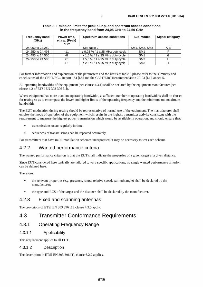
Table 3: Emission limits for peak e.i.r.p. and spectrum access conditions in the frequency band from 24,05 GHz to 24,50 GHz
Frequency band (GHz)
Power limit, e.i.r.p. (Peak)
dBm
Spectrum access conditions Sub-modes Signal category
24,050 to 24,250 See table 2 SM1, SM2, SM3 A-E 24,250 to 24,495 -11 ≤ 0,25 % / 1 s/25 MHz duty cycle SM1 F 24,495 to 24,500 -8 ≤ 1,5 % / 1 s/25 MHz duty cycle SM1 G 24,250 to 24,500 20 ≤ 5,6 % / 1 s/25 MHz duty cycle SM2 H
16 ≤ 2,3 % / 1 s/25 MHz duty cycle SM3 I
For further information and explanation of the parameters and the limits of table 3 please refer to the summary and conclusions of the CEPT/ECC Report 164 [i.8] and the CEPT/ERC Recommendation 70-03 [i.1], annex 5.
All operating bandwidths of the equipment (see clause 4.3.1) shall be declared by the equipment manufacturer (see clause 4.2 of ETSI EN 303 396 [1]).
Where equipment has more than one operating bandwidth, a sufficient number of operating bandwidths shall be chosen for testing so as to encompass the lower and higher limits of the operating frequency and the minimum and maximum bandwidth.
The EUT modulation during testing should be representative of normal use of the equipment. The manufacturer shall employ the mode of operation of the equipment which results in the highest transmitter activity consistent with the requirement to measure the highest power transmission which would be available in operation, and should ensure that:
• transmissions occur regularly in time;
• sequences of transmissions can be repeated accurately.
For transmitters that have multi-modulation schemes incorporated, it may be necessary to test each scheme.
4.2.2 Wanted performance criteria
The wanted performance criterion is that the EUT shall indicate the properties of a given target at a given distance.
Since EUT considered here typically are tailored to very specific applications, no single wanted performance criterion can be defined here.
Therefore:
• the relevant properties (e.g. presence, range, relative speed, azimuth angle) shall be declared by the manufacturer;
• the type and RCS of the target and the distance shall be declared by the manufacturer.
4.2.3 Fixed and scanning antennas
The provisions of ETSI EN 303 396 [1], clause 4.3.5 apply.
4.3 Transmitter Conformance Requirements
4.3.1 Operating Frequency Range
4.3.1.1 Applicability
This requirement applies to all EUT.
4.3.1.2 Description
The description in ETSI EN 303 396 [1], clause 6.2.2 applies.

ETSI
Draft ETSI EN 302 858 V2.1.0 (2016-04) 10
4.3.1.3 Limits
For narrowband radar equipment, the upper and lower limits of the operating frequency range shall meet the following conditions:
• fH ≤ 24,25 GHz.
• fL ≥ 24,05 GHz.
For WLAM radar equipment, the upper and lower limits of the operating frequency range shall meet the following conditions:
• fH ≤ 24,50 GHz.
• fL ≥ 24,05 GHz.
4.3.1.4 Conformance
The conformance test suite for operating frequency range shall be as defined in clause 6.3.2 of ETSI EN 303 396 [1].
Conformance shall be established under normal and extreme test conditions defined in clause 4.1.
The interpretation of the results for the measurement uncertainty shall be as given in clause 4.6 of ETSI EN 303 396 [1].
4.3.2 Peak Power
4.3.2.1 Applicability
This requirement applies to all EUT.
4.3.2.2 Description
The description in ETSI EN 303 396 [1], clause 6.2.4 applies.
4.3.2.3 Limits
For narrowband radar equipment, the peak power shall not be greater than the limits in table 4.
Table 4: Narrowband radar limits for maximum radiated peak power [i.2]
Signal category Frequency range Maximum radiated peak power (e.i.r.p.)
Comments
A 24,05 GHz to 24,075 GHz 20 dBm B 24,075 GHz to 24,15 GHz -10 dBm Alternatively to C or D
C, D 24,075 GHz to 24,15 GHz 20 dBm See also the note E 24,15 GHz to 24,25 GHz 20 dBm
NOTE: Additional conditions and limits for dwell time and repetition time according to clause 4.2 shall be met.
For WLAM radar equipment, the peak power shall not be greater than the limits in table 5.
Table 5: WLAM radar limits for maximum radiated peak power [i.2]
Signal category Frequency range Maximum radiated peak power (e.i.r.p.)
Comments
A, B, C, D, E 24,05 GHz to 24,25 GHz see table 4 SM1, SM2, SM3 F 24,25 GHz to 24,495 GHz -11 dBm SM1 G 24,495 to 24,500 GHz - 8 dBm SM1 H 24,250 to 24,500 GHz 20 dBm SM2 I 24,250 to 24,500 GHz 16 dBm SM3
ETSI
Draft ETSI EN 302 858 V2.1.0 (2016-04) 11
4.3.2.4 Conformance
The conformance test suite for peak power shall be as defined in clause 6.3.3 of ETSI EN 303 396 [1].
Conformance shall be established under normal and extreme test conditions defined in clause 4.1.
The interpretation of the results for the measurement uncertainty shall be as given in clause 4.6 of ETSI EN 303 396 [1].
4.3.3 Unwanted emissions in the out-of-band domain
4.3.3.1 Applicability
This requirement applies to all EUT.
4.3.3.2 Description
The description in ETSI EN 303 396 [1], clause 6.2.11 applies.
4.3.3.3 Limits
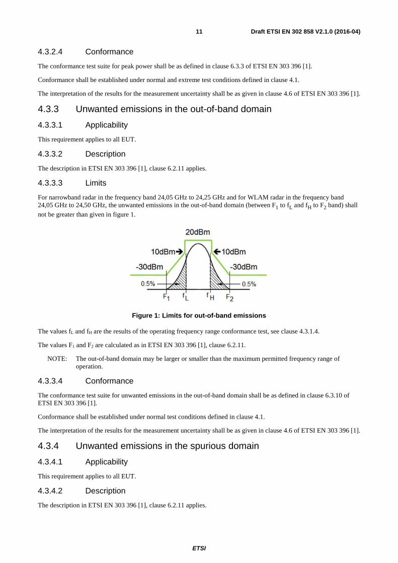
For narrowband radar in the frequency band 24,05 GHz to 24,25 GHz and for WLAM radar in the frequency band 24,05 GHz to 24,50 GHz, the unwanted emissions in the out-of-band domain (between F1 to fL and fH to F2 band) shall
not be greater than given in figure 1.
Figure 1: Limits for out-of-band emissions
The values fL and fH are the results of the operating frequency range conformance test, see clause 4.3.1.4.
The values F1 and F2 are calculated as in ETSI EN 303 396 [1], clause 6.2.11.
NOTE: The out-of-band domain may be larger or smaller than the maximum permitted frequency range of operation.
4.3.3.4 Conformance
The conformance test suite for unwanted emissions in the out-of-band domain shall be as defined in clause 6.3.10 of ETSI EN 303 396 [1].
Conformance shall be established under normal test conditions defined in clause 4.1.
The interpretation of the results for the measurement uncertainty shall be as given in clause 4.6 of ETSI EN 303 396 [1].
4.3.4 Unwanted emissions in the spurious domain
4.3.4.1 Applicability
This requirement applies to all EUT.
4.3.4.2 Description
The description in ETSI EN 303 396 [1], clause 6.2.11 applies.

ETSI
Draft ETSI EN 302 858 V2.1.0 (2016-04) 12
4.3.4.3 Limits
For narrowband radar in the frequency band 24,05 GHz to 24,25 GHz and for WLAM radar in the frequency band 24,05 GHz to 24,50 GHz, the effective radiated power of any spurious emission shall not be greater than the values given in table 6.
Table 6: Limits for radiated spurious emissions [i.4]
Frequency range (MHz) Limit values for spurious radiation Detector type 47 to 74 -54 dBm e.r.p. Quasi-Peak
87,5 to 118 -54 dBm e.r.p. Quasi-Peak 174 to 230 -54 dBm e.r.p. Quasi-Peak 470 to 790 -54 dBm e.r.p. Quasi-Peak
otherwise in band 30 to 1 000 -36 dBm e.r.p. Quasi-Peak f > 1 000 to 50 000 (see note) -30 dBm e.i.r.p. Mean
NOTE: According to CEPT/ERC/REC 74-01 [i.4], spurious emission is measured up to the 2nd harmonic of the fundamental frequency. In this case, the upper frequency limit up to which measurements are performed is 50 GHz.
4.3.4.4 Conformance
The conformance test suite for unwanted emissions in the spurious domain shall be as defined in clause 6.3.10 of ETSI EN 303 396 [1].
Conformance shall be established under normal test conditions defined in clause 4.1.
The interpretation of the results for the measurement uncertainty shall be as given in clause 4.6 of ETSI EN 303 396 [1].
4.4 Receiver Conformance Requirements
4.4.1 Introduction
ETSI EG 203 336 [i.5] lists candidate technical parameters to be included in a Harmonised Standard aimed at providing a presumption of conformity of radio equipment with the essential requirements in articles 3.1(b) and 3.2 of the Directive 2014/53/EU [i.3].
Essential requirements are high level objectives described in European Directives. The purpose of the Harmonised Standard is to translate those high level objectives into detailed technical specifications.
The present document applies to radar systems for which the "classical" receiver parameters are not necessarily relevant. Where applicable, suitable alternative technical requirements are included, see clause 4.4.3.
4.4.2 Receiver spurious emissions
4.4.2.1 Applicability
Receiver spurious emission testing shall apply for any mode other than transmit mode.
NOTE: Otherwise receiver spurious emissions are measured as part of the transmitter spurious emissions, see clause 4.3.4.
4.4.2.2 Description
The description in ETSI EN 303 396 [1], clause 6.2.12 applies.
4.4.2.3 Limits
For narrowband radar and for WLAM radar, the effective radiated power of any narrowband spurious emissions of the receiver shall not be greater than the values given in table 7.

ETSI
Draft ETSI EN 302 858 V2.1.0 (2016-04) 13
Table 7: Narrowband spurious emission limits for receivers
Frequency range Limit Detector type 30 MHz to 1 GHz -57 dBm (e.r.p.) Quasi-Peak
above 1 GHz to 50 GHz (see note) -47 dBm (e.i.r.p.) Mean NOTE: According to CEPT/ERC/REC 74-01 [i.4], spurious emission is measured up
to the 2nd harmonic of the fundamental frequency. In this case, the upper frequency limit up to which measurements are performed is 50 GHz.
For narrowband radar and for WLAM radar, the effective radiated power of any wideband receiver spurious emissions shall not be greater than the values given in table 8.
Table 8: Wideband spurious emission limits for receivers
Frequency range Limit Detector type 30 MHz to 1 GHz -47 dBm/MHz (e.r.p.) Quasi-Peak
above 1 GHz to 50 GHz (see note) -37 dBm/MHz (e.i.r.p.) Mean NOTE: According to CEPT/ERC/REC 74-01 [i.4], spurious emission is measured
up to the 2nd harmonic of the fundamental frequency. In this case, the upper frequency limit up to which measurements are performed is 50 GHz.
4.4.2.4 Conformance
The conformance test suite for receiver spurious emissions shall be as defined in clause 6.3.11 of ETSI EN 303 396 [1].
Conformance shall be established under normal test conditions defined in clause 4.1.
The interpretation of the results for the measurement uncertainty shall be as given in clause 4.6 of ETSI EN 303 396 [1].
4.4.3 Receiver in-band, out-of-band and remote-band signals handling
4.4.3.1 Applicability
This requirement applies to all EUT.
4.4.3.2 Description
The description in ETSI EN 303 396 [1], clause 6.2.13 applies.
4.4.3.3 Limits
The EUT shall achieve the wanted performance criterion, see clause 4.2.2, in the presence of unwanted signals defined in ETSI EN 303 396 [1], clause 6.3.12.4.
If the wanted performance criterion is not achieved then the EUT shall issue a respective blindness message.
4.4.3.4 Conformance
The conformance test suite for receiver in-band, out-of-band and remote-band signals handling shall be as defined in clause 6.3.12 of ETSI EN 303 396 [1].
Conformance shall be established under normal test conditions defined in clause 4.1.
The interpretation of the results for the measurement uncertainty shall be as given in clause 4.6 of ETSI EN 303 396 [1].
4.4.4 Receiver sensitivity
Receiver sensitivity is not specified in the present document in order to allow manufacturers the freedom to tailor equipment to specific circumstances.
For instance, equipment covered by the present document may be intended to detect a target at maximum range or may be intended to discriminate features such as size, shape or velocity at shorter range. The level of minimum usable signal would be different in each case.

ETSI
Draft ETSI EN 302 858 V2.1.0 (2016-04) 14
4.5 Requirements for Spectrum Access
4.5.1 Spectrum Access Duty Cycle
4.5.1.1 Applicability
This requirement applies only to WLAM radars.
4.5.1.2 Description
The description in ETSI EN 303 396 [1], clause 6.2.8 applies.
4.5.1.3 Limits
For WLAM radar, the spectrum access duty cycle shall not be greater than the values given in table 9.
Table 9: Limits for spectrum access duty cycle
Signal category
Frequency range Observation bandwidth Observation time
Duty Cycle
F 24,25 GHz to 24,495 GHz 25 MHz,
anywhere inside the given frequency range
1 s 0,25 %
G 24,495 GHz to 24,50 GHz
5 MHz
1 s
1,5 % including scaling from 5 MHz observation
bandwidth to 25 MHz bandwidth
H 24,25 GHz to 24,50 GHz 25 MHz,
anywhere inside the given frequency range
1 s 5,6 % during activation
I 24,25 GHz to 24,50 GHz 25 MHz,
anywhere inside the given frequency range
1 s 2,3 % during activation
4.5.1.4 Conformance
The conformance test suite for spectrum access duty cycle shall be as defined in clause 6.3.7 of ETSI EN 303 396 [1].
Conformance shall be established under normal test conditions defined in clause 4.1.
The interpretation of the results for the measurement uncertainty shall be as given in clause 4.6 of ETSI EN 303 396 [1].
4.5.2 Dwell Time and Repetition Time
4.5.2.1 Applicability
This requirement applies only to EUT which utilize signal categories C or D (see also clause 4.2).
4.5.2.2 Description
The description in ETSI EN 303 396 [1], clause 6.2.9 apply.
4.5.2.3 Limits
For EUT utilizing signal categories C or D, the limits for dwell time and repetition time given in table 10 shall be met.

ETSI
Draft ETSI EN 302 858 V2.1.0 (2016-04) 15
Table 10: Limits for dwell time and repetition time
Signal category
Frequency range
Observation bandwidth
Observation time
Dwell time Repetition time
C
24,075 GHz to 24,15 GHz
40 kHz, anywhere inside the
given frequency range 3 ms
Radar device mounted behind a bumper: accumulated dwell time ≤ 4 µs. Radar device mounted without a bumper: accumulated dwell time ≤ 3 µs.
n/a
D 24,075 GHz to
24,15 GHz
40 kHz, anywhere inside the
given frequency range
See ETSI EN 303 396 [1], clause 6.3.8.3
Repeating dwell time ≤ 1 ms
≥ 40 ms
NOTE: Relevant for these limits are only signal portions with a signal power larger than -10 dBm e.i.r.p. (peak).
4.5.2.4 Conformance
The conformance test suite for dwell time and repetition time shall be as defined in clause 6.3.8 of ETSI EN 303 396 [1].
Conformance shall be established under normal test conditions defined in clause 4.1.
The interpretation of the results for the measurement uncertainty shall be as given in clause 4.6 of ETSI EN 303 396 [1].
4.5.3 Frequency Modulation Range
4.5.3.1 Applicability
This requirement applies only to EUT which utilize signal categories C or D (see also clause 4.2).
4.5.3.2 Description
The description in ETSI EN 303 396 [1], clause 6.2.10 apply.
4.5.3.3 Limits
For EUT utilizing signal categories C or D, the frequency modulation range shall not be smaller than the values given in table 11.
Table 11: Limits for frequency modulation range
Signal category Observation bandwidth Observation time Frequency modulation range C 24,075 GHz to 24,15 GHz ≥ EUT cycle time 250 kHz D 24,075 GHz to 24,15 GHz ≥ EUT cycle time 250 kHz
NOTE: Relevant for these limits are only signal portions with a signal power larger than -10 dBm e.i.r.p. (peak).
4.5.3.4 Conformance
The conformance test suite for frequency modulation range shall be as defined in clause 6.3.9 of ETSI EN 303 396 [1].
Conformance shall be established under normal test conditions defined in clause 4.1.
The interpretation of the results for the measurement uncertainty shall be as given in clause 4.6 of ETSI EN 303 396 [1].
ETSI
Draft ETSI EN 302 858 V2.1.0 (2016-04) 16
4.6 Antenna Requirements
4.6.1 Unwanted vertical plane transmitter emissions in the 23,6 GHz to 24,0 GHz band
4.6.1.1 Applicability
This requirement applies only to WLAM radars.
4.6.1.2 Description
The vertical plane transmitter emissions are defined as emissions of the antenna as a function of the elevation angle, normalized to the maximum emission at boresight.
4.6.1.3 Limits
For WLAM radar, the unwanted vertical radiated emissions between 23,6 GHz and 24,0 GHz shall not be larger than -71,0 dBm/MHz e.i.r.p. RMS.
Additionally, the average antenna attenuation shall achieve at least 20 dB above a 30° elevation.
4.6.1.4 Conformance
The conformance test suite for unwanted vertical plane transmitter emissions in the 23,6 GHz to 24,0 GHz band shall be as defined in clause 7.2.1.
Conformance shall be established under normal test conditions defined in clause 4.1.
The interpretation of the results for the measurement uncertainty shall be as given in clause 4.6 of ETSI EN 303 396 [1].
4.7 Other Requirements and Mitigation techniques
4.7.1 Installation requirements
4.7.1.1 Applicability
This requirement applies to all EUT.
4.7.1.2 Description
This clause includes requirements relating to the installation of the EUT in a vehicle.
4.7.1.3 Requirements
The EUT shall be installed at a permanent fixed position on a vehicle.
4.7.1.4 Conformance
Conformance shall be conditional on the correct installation described above. Installation instructions shall be made available by the manufacturer.
5 Testing for compliance with technical requirements
5.1 General The provisions of ETSI EN 303 396 [1], clause 4, shall apply except as varied or added herein.

ETSI
Draft ETSI EN 302 858 V2.1.0 (2016-04) 17
5.2 Product information The following product information shall be given by the manufacturer in addition to clause 4.2 of ETSI EN 303 396 [1]:
• Installation of the EUT with bumper or without bumper.
6 Test setup and procedures The provisions of ETSI EN 303 396 [1], clause 5 shall apply except as varied herein.
7 Conformance methods of measurement
7.1 General The provisions of ETSI EN 303 396 [1], clause 6 shall apply except as varied or added herein.
All measurement results shall be recorded in a test report, see clause 4.7 in ETSI EN 303 396 [1].
7.2 Conformance test suites for antenna requirements
7.2.1 Unwanted vertical plane transmitter emissions in the 23,6 GHz to 24,0 GHz band
The following steps shall be performed:
• The EUT is fixed on a mechanism that allows pivoting of the device either in a vertical or horizontal plane in both directions up to minimum of 90°. The EUT is fixed in a way that its elevation plane coincides with the pivoting plane. The maximum bore sight direction is adjusted and referred to as the 0° origin.
• A spectrum analyser with peak detector in max-hold with largest RBW and VBW possible is used as measuring receiver.
• The EUT shall be operated in the WLAM Mode.
• The measurement of the EUT shall be done at 23,6 GHz, 23,8 GHz and 24 GHz.
• Only the relative attenuation to the maximum bore sight direction shall be measured.
• The EUT is turned 90° to the left and right from the bore sight direction in steps of ≤ 2° and the respective emission values are noted.
• Determine the relative emission attenuation from the bore sight maximum value to both sides (e.g. in a polar-log antenna diagram).
This measurement has to be performed for sub-modes SM1 and SM2 for front radar, and SM3 for rear facing radar separately.

ETSI
Draft ETSI EN 302 858 V2.1.0 (2016-04) 18
Annex A (normative): Relationship between the present document and the essential requirements of Directive 2014/53/EU The present document has been prepared under the Commission's standardisation request C(2015) 5376 final [i.9] to provide one voluntary means of conforming to the essential requirements of Directive 2014/53/EU on the harmonisation of the laws of the Member States relating to the making available on the market of radio equipment and repealing Directive 1999/5/EC [i.3].
Once the present document is cited in the Official Journal of the European Union under that Directive, compliance with the normative clauses of the present document given in table A.1 confers, within the limits of the scope of the present document, a presumption of conformity with the corresponding essential requirements of that Directive, and associated EFTA regulations.
Table A.1: Relationship between the present document and the essential requirements of Directive 2014/53/EU
Harmonised Standard ETSI EN 302 858 The following requirements are relevant to the presumption of conformity
under the article 3.2 of Directive 2014/53/EU [i.3] Requirement Requirement Conditionality
No Description Reference: Clause No U/C Condition
1 Operating Frequency Range 4.3.1 U 2 Peak Power 4.3.2 U 3 Unwanted emissions in the
out-of-band domain 4.3.3 U
4 Unwanted emissions in the spurious domain
4.3.4 U
5 Receiver spurious emissions 4.4.2 C It applies for any mode other than transmit mode.
6 Receiver in-band, out-of-band and remote-band signals handling
4.4.3 U
7 Spectrum access duty cycle 4.5.1 C It applies only to WLAM radars. 8 Dwell time and repetition time 4.5.2 C It applies only to EUT which utilize signal
categories C or D (see also clause 4.2). 9 Frequency modulation range 4.5.3 C It applies only to EUT which utilize signal
categories C or D (see also clause 4.2). 10 Unwanted vertical plane transmitter
emissions in the 23,6 GHz to 24,0 GHz band
4.6.1 C It applies only to WLAM radars.
11 Installation requirements 4.7.1 U
Key to columns:
Requirement:
No A unique identifier for one row of the table which may be used to identify a requirement.
Description A textual reference to the requirement.
Clause Number Identification of clause(s) defining the requirement in the present document unless another document is referenced explicitly.
Requirement Conditionality:
U/C Indicates whether the requirement shall be unconditionally applicable (U) or is conditional upon the manufacturers claimed functionality of the equipment (C).
Condition Explains the conditions when the requirement shall or shall not be applicable for a requirement which is classified "conditional".

ETSI
Draft ETSI EN 302 858 V2.1.0 (2016-04) 19
Presumption of conformity stays valid only as long as a reference to the present document is maintained in the list published in the Official Journal of the European Union. Users of the present document should consult frequently the latest list published in the Official Journal of the European Union.
Other Union legislation may be applicable to the product(s) falling within the scope of the present document.

ETSI
Draft ETSI EN 302 858 V2.1.0 (2016-04) 20
Annex B (informative): Change History
Date Version Information about changes
January 2016 2.1.1_0.0.1 Initial version, used TGUWB HS skeleton as basis, overtaken content from R&TTE EN 302 858, made references to new ETSI EN 303 396
January 2016 2.1.1_0.0.3 Added more details to Rx interference testing, refined formulation for putting results into test report, smaller improvements in many places
January 2016 2.1.1_0.0.4 Definitions referenced to ETSI EN 303 396, cleared table and figure numbering, smaller improvements in many places
January 2016 2.1.1_0.0.5 Version for TGSRR#23 January 2016 2.1.1_0.0.6 Version resulted from TGSRR#23 for approval by remote consensus January 2016 2.1.1_0.0.7 First revision during RC to collect the comments February 2016 2.1.1_0.0.8 Second revision during RC to collect the comments February 2016 2.1.1_1.0.0 Revision during resolution GoTo meeting for HS on ENAP

ETSI
Draft ETSI EN 302 858 V2.1.0 (2016-04) 21
History
Document history
V1.2.1 July 2011 Publication as ETSI EN 302 858 part 1 and part 2
V1.3.1 November 2013 Publication as ETSI EN 302 858 part 1 and part 2
V2.1.0 April 2016 EN Approval Procedure AP 20160717: 2016-04-18 to 2016-07-18