Embed Size (px)
Citation preview

Dräger X-am 2500(MQG 0011)Technical Manual
i


Content
Dräger X-am 2500 3
Content
1 For your safety . . . . . . . . . . . . . . . . . . . . . . . . . . . 41.1 General safety statements . . . . . . . . . . . . . . . . . . . 41.2 Definitions of alert icons . . . . . . . . . . . . . . . . . . . . . 4
2 Description . . . . . . . . . . . . . . . . . . . . . . . . . . . . . . 52.1 Product overview . . . . . . . . . . . . . . . . . . . . . . . . . . . 52.1.1 Front . . . . . . . . . . . . . . . . . . . . . . . . . . . . . . . . . . . . 52.1.2 Rear side . . . . . . . . . . . . . . . . . . . . . . . . . . . . . . . . . 52.1.3 Display . . . . . . . . . . . . . . . . . . . . . . . . . . . . . . . . . . 52.1.4 Special symbols . . . . . . . . . . . . . . . . . . . . . . . . . . . 52.2 Intended use . . . . . . . . . . . . . . . . . . . . . . . . . . . . . . 62.3 Approvals . . . . . . . . . . . . . . . . . . . . . . . . . . . . . . . . 62.3.1 Marking . . . . . . . . . . . . . . . . . . . . . . . . . . . . . . . . . . 62.3.2 Permitted power packs . . . . . . . . . . . . . . . . . . . . . . 62.3.3 Safety Instructions . . . . . . . . . . . . . . . . . . . . . . . . . . 7
3 Use . . . . . . . . . . . . . . . . . . . . . . . . . . . . . . . . . . . . . 83.1 Preparations for use . . . . . . . . . . . . . . . . . . . . . . . . 83.1.1 Charging the batteries . . . . . . . . . . . . . . . . . . . . . . . 83.1.2 Replacing the batteries / rechargeable batteries . . . 93.1.3 Switching on the instrument . . . . . . . . . . . . . . . . . . 93.1.4 Switching off the instrument . . . . . . . . . . . . . . . . . 103.2 Before entering the workplace . . . . . . . . . . . . . . . 103.3 Configuration . . . . . . . . . . . . . . . . . . . . . . . . . . . . . 113.3.1 Standard gas configuration . . . . . . . . . . . . . . . . . . 113.3.2 Standard instrument configuration . . . . . . . . . . . . 123.3.3 Configuring the device . . . . . . . . . . . . . . . . . . . . . 123.3.4 Export data memory and display graphically . . . . 133.4 Running the bump test . . . . . . . . . . . . . . . . . . . . . 133.4.1 Manual implementation without documentation of the
results in the instrument memory . . . . . . . . . . . . . 133.4.2 Menu implementation with the documentation of
results in the instrument memory . . . . . . . . . . . . . 143.4.3 Automatic implementation with the
Bump Test Station . . . . . . . . . . . . . . . . . . . . . . . . . 143.5 During operation . . . . . . . . . . . . . . . . . . . . . . . . . . 153.6 Identifying alarms . . . . . . . . . . . . . . . . . . . . . . . . . 153.6.1 Concentration pre-alarm A1 . . . . . . . . . . . . . . . . . 153.6.2 Concentration main alarm A2 . . . . . . . . . . . . . . . . 163.6.3 STEL / TWA exposure alarm . . . . . . . . . . . . . . . . 163.6.4 Battery pre-alarm . . . . . . . . . . . . . . . . . . . . . . . . . 163.6.5 Battery main alarm . . . . . . . . . . . . . . . . . . . . . . . . 163.6.6 Instrument alarm . . . . . . . . . . . . . . . . . . . . . . . . . . 16
4 Menu functions . . . . . . . . . . . . . . . . . . . . . . . . . . 174.1 Activating the Info mode . . . . . . . . . . . . . . . . . . . . 174.2 Opening Info-Off Mode . . . . . . . . . . . . . . . . . . . . . 174.3 Quick Menu . . . . . . . . . . . . . . . . . . . . . . . . . . . . . . 174.3.1 Quick menu functions . . . . . . . . . . . . . . . . . . . . . . 174.3.2 Opening the Quick Menu . . . . . . . . . . . . . . . . . . . 174.3.3 Quick menu "Delete peak values" . . . . . . . . . . . . . 174.4 Calibration Menu . . . . . . . . . . . . . . . . . . . . . . . . . . 174.4.1 Calibration menu functions . . . . . . . . . . . . . . . . . . 174.4.2 Open the Calibration Menu . . . . . . . . . . . . . . . . . . 17
5 Calibrate instrument . . . . . . . . . . . . . . . . . . . . . . 185.1 Adjustment interval: . . . . . . . . . . . . . . . . . . . . . . . . 185.2 Run fresh air calibration . . . . . . . . . . . . . . . . . . . . 185.3 1-button calibration . . . . . . . . . . . . . . . . . . . . . . . . 195.3.1 Calibrating the sensitivity for an individual measuring
channel . . . . . . . . . . . . . . . . . . . . . . . . . . . . . . . . . 195.3.2 Sensitivity calibration for CatEx . . . . . . . . . . . . . . . 20
6 Operation with pump . . . . . . . . . . . . . . . . . . . . . 21
7 Replacing the sensors . . . . . . . . . . . . . . . . . . . . 21
8 Troubleshooting . . . . . . . . . . . . . . . . . . . . . . . . . 228.1 Warning messages . . . . . . . . . . . . . . . . . . . . . . . . 228.2 Fault message . . . . . . . . . . . . . . . . . . . . . . . . . . . . 24
9 Maintenance . . . . . . . . . . . . . . . . . . . . . . . . . . . . . 279.1 Maintenance table . . . . . . . . . . . . . . . . . . . . . . . . . 279.2 Cleaning . . . . . . . . . . . . . . . . . . . . . . . . . . . . . . . . 27
10 Storage . . . . . . . . . . . . . . . . . . . . . . . . . . . . . . . . . 27
11 Disposal . . . . . . . . . . . . . . . . . . . . . . . . . . . . . . . . 2711.1 WEEE . . . . . . . . . . . . . . . . . . . . . . . . . . . . . . . . . . 2711.2 Battery disposal . . . . . . . . . . . . . . . . . . . . . . . . . . . 2711.3 Electrochemical sensors . . . . . . . . . . . . . . . . . . . . 27
12 Technical data . . . . . . . . . . . . . . . . . . . . . . . . . . . 2812.1 X-am 2500 . . . . . . . . . . . . . . . . . . . . . . . . . . . . . . . 2812.2 Sensor data . . . . . . . . . . . . . . . . . . . . . . . . . . . . . . 29
13 Order list . . . . . . . . . . . . . . . . . . . . . . . . . . . . . . . 31
14 Declaration of conformity . . . . . . . . . . . . . . . . . . 32

4 Dräger X-am 2500
For your safety
1 For your safety
1.1 General safety statements Before using this product, carefully read the associated
Instructions for Use. This document does not replace theInstructions for Use.
1.2 Definitions of alert iconsThe following alert icons are used in this document to provideand highlight areas of the associated text that require a greaterawareness by the user. A definition of the meaning of eachicon is as follows:
WARNINGIndicates a potentially hazardous situation which,if not avoided, could result in death or serious injury.
CAUTIONIndicates a potentially hazardous situation which, if notavoided, could result in physical injury, or damage tothe product or environment. It may also be used toalert against unsafe practices.
NOTICEIndicates additional information on how to usethe product.
!
!
ii

Description
Dräger X-am 2500 5
2 Description
2.1 Product overview
2.1.1 Front
2.1.2 Rear side
2.1.3 Display
Display for 4 measuring channels:
otherwise:
The following only shows the instrument version with4 measuring channels.
2.1.4 Special symbols
1 Gas entry2 Alarm LED3 Horn4 key5 key6 Display7 Tool for changing sensor
1 IR interface2 Fastening clip3 Nameplate4 Charging contacts5 Power pack6 Serial no.
00133366.eps
0
1
2
6
5 4
3
2
X-am 2500
7
OK
00233366.eps
2
1
4
63
5
1 Measured gas display with unit2 Measuring value display3 Special symbols
4 Measured gas display5 Measured value display with unit6 Special symbols
Fault message, see section 4.1 on page 17Warning message, see section 4.1 on page 17Display of peak values for all measured gases,see section 4.1 on page 17The exposure evaluation display (TWA) for measuredgases, e.g. H2S and CO, see section 4.1 on page 17The exposure evaluation display (STEL) for measuredgases, e.g. H2S und CO, see section 4.1 on page 17The instrument is set to the bump test function,see section 3.4 on page 13The instrument is set to the fresh air calibration function,see section 5.2 on page 18The instrument is set to the 1-button calibration/adjustment function, see section 5.3 on page 19The instrument is set to the single gas calibrationfunction, see section 5.3.1 on page 19Function for password input is active, see section 4.4on page 17
Battery / rechargeable battery 100 % fullBattery / rechargeable battery 2/3 fullBattery / rechargeable battery 1/3 fullBattery / rechargeable battery empty
00333366_en.eps
4 5 6
ch4
O2
CO
1 2 3
ch4 %LEL0.0
O2 Vol%20.9
CO ppm0.0
H2S ppm0.0
%LEL0.0
Vol%20.9
ppm0.0
6 Dräger X-am 2500
Description
2.2 Intended usePortable gas detection instrument for the continuousmonitoring of the concentration of several gases in the ambientair within the working area and in explosion-hazard areas.Independent measurement of up to 4 gases, in accordancewith the installed Dräger sensors.
Areas subject to explosion hazards, classified by zonesThe instrument is intended for the use in areas that are at riskfor explosions in Zone 0, Zone 1 or Zone 2 or in mines at riskdue to black damp. It is intended for use within a temperaturerange of -20 °C to +50 °C, and for areas in which gases ofexplosion groups IIA, IIB or IIC and temperature class T3 or T4(depending on the batteries and rechargeable battery) may bepresent. For zone 0, the temperature class is limited to T3.If used in mines, the instrument is only to be used in areasknown to have a low risk of mechanical impact.
Areas subject to explosion hazards, classified by divisionsThe instrument is intended for the use in areas that are at riskfor explosions of Class I&II, Div. 1 or Div. 2. It is intended foruse within a temperature range of –20 °C to +50 °C, and forareas in which gases or dusts of groups A, B, C, D or E, F, G,and temperature class T3 or T4 (depending on the batteriesand rechargeable battery) may be present.
2.3 ApprovalsThe approvals are shown on the rating plate. The technicalapprovals are valid for the X-am 2500 gas detection instrumentand the calibration cradle. The explosion-protection approvalsare only valid for the X-am 2500 gas detection instrument; thecalibration cradle must not be used in the Ex zone.The BVS 10 ATEX E 080 X technical suitability test is based onthe calibration with the target gas.
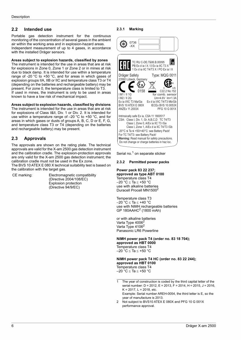
2.3.1 Marking
Serial no.1 on separate sticker
2.3.2 Permitted power packs
Power pack 83 22 237;approved as type ABT 0100Temperature class T4–20 °C Ta +50 °Cuse with alkaline batteriesDuracell Procell MN15002
Temperature class T3–20 °C Ta +40 °Cuse with NiMH rechargeable batteriesGP 180AAHC2 (1800 mAh)
or with alkaline batteriesVarta Type 40062
Varta Type 41062
Panasonic LR6 Powerline
NiMH power pack T4 (order no. 83 18 704);approved as HBT 0000Temperature class T4–20 °C Ta +50 °C
NiMH power pack T4 HC (order no. 83 22 244);approved as HBT 0100Temperature class T4–20 °C Ta +50 °C
CE marking: Electromagnetic compatibility (Directive 2004/108/EC)Explosion protection (Directive 94/9/EC)
1 The year of construction is coded by the third capital letter of the serial number: D = 2012, E = 2013, F = 2014, H = 2015, J = 2016, K = 2017, L = 2018, etc.Example: Serial number AREH-0054, the third letter is E, so the year of manufacture is 2013.
2 Not subject to BVS10 ATEX E 080X and PFG 10 G 001X performance approval.

Description
Dräger X-am 2500 7
2.3.3 Safety Instructions Note the following for CSA (Canadian Standards Association)applications:For the CSA approval only the functions of the devicecomponent that is used to measure flammable gases aretested. The device is not approved by CSA for use in mining.
WARNINGDo not replace or charge batteries in potentiallyexplosive areas. Explosion hazard!
Charge the NiMH power pack T4 (type HBT 0000) orT4 HC (type HBT 0100) with the associated Drägercharger. Charge NiMH single cells for ABT 0100battery holder in accordance with the manufacturer'sspecifications. Ambient temperature during thecharging process: 0 to +40 °C.
To reduce the danger of explosion, do not mix newbatteries with old batteries and do not mix batteriesmade by different manufacturers.
Always disconnect the instrument from the power packbefore carrying out any maintenance operations.
Substitution of components may impair intrinsic safety.
Only use power packs ABT 0100 (order no. 83 22 237),HBT 0000 (order no. 83 18 704) or HBT 0100 (order no.83 22 244). See marking on power pack for approvedbatteries and related temperature classes.
Not tested in an oxygen-enriched atmosphere(>21 % O2).
High off-scale readings may indicate an explosiveconcentration.
!
WARNINGBefore daily use, test the sensitivity with a knownconcentration of the applicable gas corresponding to25 to 50% of the maximum concentration. Theaccuracy must be within a range of 0 to +20% of theactual value. Perform a calibration to correct theaccuracy if necessary.
!

8 Dräger X-am 2500
Use
3 Use
3.1 Preparations for use Before using the instrument for the first time, insert the
batteries provided or a charged NiMH power pack T4(type HBT 0000; order no. 83 18 704) / T4 HC(type HBT 0100; order no. 83 22 244), see section 3.1.2on page 9.
The instrument is now ready for operation.
3.1.1 Charging the batteries
To maintain the lifetime of the batteries, charging istemperature controlled and only performed in a temperaturerange of 5 to 35 °C. When outside this temperature range,the charging automatically interrupted and automaticallyrecommenced after the temperature range has beenreached again.
The charging time is typically 4 hours. A new NiMH power pack reaches its full capacity after three
complete charging/discharging cycles. Never store the instrument for extended periods without
being connected to a power source (maximum of2 months) because the internal buffer battery will drain.
Charging with the multiple charging station A maximum of 20 instruments can be charged at the same
time on the power pack (order no. 83 18 805) of themultiple charging station.
When attaching the charging modules, disconnect thepower pack from the mains supply!
Position the instrument on an even and level surface.1. Turn the slots of the interlock into a horizontal position by
using a screwdriver or coin.2. Insert the fastening lug (2) of the charger module
(simultaneous power feed) until it engages.3. Close the lock (1) with a quarter turn (slot is positioned
vertically).4. Attach additional charging modules in the same way.5. Connect the power pack to the mains.
The green "Mains" LED (1) is on.6. Insert the switched off instrument into the charger module.
Display LED (5) on the charging cradle:
If a fault occurs: Remove the instrument from the charging module and
insert it again. If the fault still occurs, have the charging module repaired.
It takes approx. 4 hours to fully charge an emptyrechargeable battery.
In the event of a short circuit or if the power pack isoverloaded: The red "Overload" LED (3) is on, and an audible
alarm sounds. After the fault has been corrected, the alarm is switched
off automatically and the charging process is restarted. In the event of a power failure, the instruments already
charged will be protected from discharging.
WARNINGExplosion hazard!Do not charge underground or in explosion hazard areas!
The chargers are not designed in accordance with theregulations for fire damp and explosion protection.
Charge the NiMH power pack T4 (type HBT 0000) orT4 HC (type HBT 0100) with the associated Drägercharger. Charge NiMH single cells for ABT 0100battery holder in accordance with the manufacturer'sspecifications. Ambient temperature during thecharging process: 0 to +40 °C.
NOTICEEven if the instrument is not used, Dräger recommends storing the instrument in the charging cradle (chargingmodule X-am 1/2/5000, order no. 83 18 639).
CAUTIONAlways connect or disconnect the charging modulesindividually and not in groups in order to prevent thecharging station from becoming damaged. Duringtransportation, the power pack and the chargingmodules should also always be handled individuallyand without inserted instruments.
!
ii
!
Charging
Fault
Full
CAUTIONA short circuit of the charging contacts in the chargingmodules, e. g., by metallic objects that have fallen in,does not result in damage to the charging station.It should, however, be avoided due to possible heatinghazards and incorrect displays on the charger module.
02733366.eps
0
2 1
0
2 1
0
2 11Ex%UEGCO2ppmO2Vol%COppmH2Sppm
Ex%UEGCO2ppmO2Vol%COppmH2Sppm
Ex%UEGCO2ppmO2Vol%COppmH2Sppm
X-am 2500 X-am 2500 X-am 2500
!
Use
Dräger X-am 2500 9
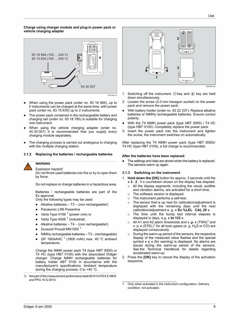
Charge using charger module and plug-in power pack or vehicle charging adapter
When using the power pack (order no. 83 16 994), up to5 instruments can be charged at the same time, with powerpack (order no. 83 15 635) up to 2 instruments.
The power pack contained in the rechargeable battery andcharging set (order no. 83 18 785) is suitable for chargingone instrument.
When using the vehicle charging adapter (order no.45 30 057) it is recommended that you supply everycharging module separately.
The charging process is carried out analogous to chargingwith the multiple charging station.
3.1.2 Replacing the batteries / rechargeable batteries
1. Switching off the instrument: key and key are helddown simultaneously.
2. Loosen the screw (2.0 mm hexagon socket) on the powerpack and remove the power pack.
With battery holder (order no. 83 22 237): Replace alkalinebatteries or NiMHy rechargeable batteries. Ensure correctpolarity.
With the T4 NiMH power pack (type HBT 0000) / T4 HC(type HBT 0100): Completely replace the power pack.
3. Insert the power pack into the instrument and tightenthe screw, the instrument switches on automatically.
After replacing the T4 NiMH power pack (type HBT 0000)/T4 HC (type HBT 0100), a full charge is recommended.
After the batteries have been replaced: The settings and data are stored when the battery is replaced.
The sensors warm up again.
3.1.3 Switching on the instrument1. Hold down the [OK] button for approx. 3 seconds until the
» 3 . 2 . 1 « countdown shown on the display has elapsed. All the display segments, including the visual, audible
and vibration alarms, are activated for a short time. The software version is displayed. The instrument performs a self-test. The sensor that is up next for calibration/adjustment is
displayed with the remaining days until the nextcalibration/adjustment e. g. » Ex %LEL CAL 20 «.
The time until the bump test interval elapses isdisplayed in days, e.g. » bt 123 «.
All A1 and A2 alarm thresholds and » « (TWA)1 and» « (STEL)1 for all toxic gases (e. g. H2S or CO) aredisplayed consecutively.
During the warm-up period of the sensors, the respectivedisplay of the measured value flashes and the specialsymbol » « (for warning) is displayed. No alarms areissued during the warm-up period of the sensors.See the Technical Handbook for details regardingaccelerated warm-up.
2. Press the [OK] key to cancel the display of the activationsequence.
WARNING
Explosion hazard!Do not throw used batteries into fire or try to open themby force.
Do not replace or charge batteries in a hazardous area.
Batteries / rechargeable batteries are part of theEx approval.Only the following types may be used: Alkaline batteries – T3 – (non rechargeable!) Panasonic LR6 Powerline Varta Type 4106 1 (power one) or Varta Type 4006 1 (industrial) Alkaline batteries – T4 – (non rechargeable!) Duracell Procell MN1500 1
NiMHy rechargeable batteries – T3 – (rechargeable) GP 180AAHC 1 (1800 mAh) max. 40 °C ambient
temperature.
Charge the NiMH power pack T4 (type HBT 0000) orT4 HC (type HBT 0100) with the associated Drägercharger. Charge NiMH rechargeable batteries forbattery holder ABT 0100 in accordance with themanufacturer's specifications. Ambient temperatureduring the charging process: 0 to +40 °C.
1) Not part of the measurement performance tests BVS10 ATEX E 080X and PFG 10 G 001X.
02833366.eps
83 16 994 (100 ... 240 V)83 15 635 (100 ... 240 V)
45 30 057
0
Ex%UEGCO2ppmO2Vol%COppmH2Sppm
X-am 2500
!
1 Only when activated in the instrument configuration. Delivery condition: not activated.
02633366.eps
1
2
3
–
+
–
+
OK

10 Dräger X-am 2500
Use
3.1.4 Switching off the instrument Press and hold the [OK] key and [ + ] key simultaneously
until the countdown » 3 . 2 . 1 « shown on the display haselapsed.Before the instrument is switched off, the visual,audible and vibration alarms are activated for a short time.
3.2 Before entering the workplace
1. Switch on the instrument. The current measured values areshown in the display.
2. Observe any warning » « or fault messages » «.
3. Check that the gas inlet opening on the instrument isnot covered.
WARNINGBefore any measurements relevant to safety aremade, check the adjustment with a bump test, adjust ifnecessary and check all alarm elements. If nationalregulations apply, a bump test must be performedaccording to the national regulations. Faultyadjustment may result in incorrect measuring results,with possible serious consequences.
The instrument can be operated normally. If the warningmessage does not disappear automatically duringoperation, the instrument must be serviced after the endof use.The instrument is not ready to measure and requiresmaintenance.
WARNINGFractions of catalytic poisons in the measuring gas(e.g. volatile silicone, sulphur, heavy metal compoundsor halogenated hydrocarbon) can damage theCatEx sensor. If the CatEx sensor can no longer becalibrated to the target concentration, the sensor mustbe replaced.
In case of measurements in an oxygen-deficientatmosphere (<8 Vol.-% O2) the CatEx sensor mayshow incorrect displays; in this case, a reliablemeasurement with a CatEx sensor is not possible.
In an oxygen enriched atmosphere (>21 vol. % O2),the explosion protection cannot be guaranteed;remove instrument from the Ex area.
!
!

Use
Dräger X-am 2500 11
3.3 Configuration
3.3.1 Standard gas configuration
DrägerSensor Measuring range 1 Alarm A1 1) Alarm A2 1)
thre
shol
d
can
be
ackn
owle
dged
sel
f-lat
chin
g
thre
shol
d
can
be
ackn
owle
dged
sel
f-lat
chin
g
CatEx 125 PR [%LEL] 0 to 100 20 yes no 40 no yesXXS O2 [Vol.-%] 0 to 25 19 2 no yes 23 no yes
XXS CO [ppm] 0 to 2000 30 yes no 60 no yesXXS H2S LC [ppm] 0 to 100 5 yes no 10 no yesXXS NO2 [ppm] 0 to 50 5 yes no 10 no yesXXS SO2 [ppm] 0 to 100 1 yes no 2 no yes
1) Different settings can be selected to meet customer requirements on delivery. The current setting can be checked and changed with the Dräger CC Vision software.A version of the CC-Vision software that can be used for Dräger X-am 2500 is available for download from the product page for the X-am 2500 at the following web address: www.draeger.com
2) With O2, A1 is the lower alarm threshold: an alarm is triggered if the value is too low.

12 Dräger X-am 2500
Use
3.3.2 Standard instrument configuration
Changing the configuration: see “Replacing the sensors” onpage 21.
3.3.3 Configuring the deviceTo individually configure a standard-configuration device,connect the device to a PC. The installed PC softwareDräger CC Vision is used for configuration.
A version of Dräger CC-Vision suitable for the Dräger X-am2500 can be downloaded on the product page of the X-am 2500:www.draeger.com.
Observe the documentation and online help of the software. A version of the CC-Vision software that can be used for
Dräger X-am 2500 is available for download from theproduct page for the X-am 2500 at the following webaddress: www.draeger.com
Device settingsThe following changes can be made to the device parametersfor a device:
Dräger X-am® 25001
1) X-am® is a registered trademark of Dräger.
Bump test mode 2
2) Different settings can be selected to meet customer requirements on delivery. The current setting can be checked and changed with the Dräger CC Vision software.
Extended bump test
Fresh-gas adjustment2) ON
Operating signal 2) 3
3) A periodic short signal indicates the operating capacity of the instrument. If there is no operating signal, correct operation cannot be guaranteed.
ON
Switch off 2) allowed
LEL factor 2)
(ch4)4.4 (vol. %)
(4.4 vol. % corresponds to 100 %LEL)
STEL 2) 4 5(short-term average)
4) STEL: average value of an exposure over a short period, generally 15 minutes.
5) Interpretation only if the sensor is designed for this.
STEL function - disabledAverage value duration = 15
minutesTWA 2) 5) 6
(shift average)
6) TWA: shift averages are workplace limit values for generally eight hours per day of exposure for five days a week during a working life.
TWA function - disabledAverage value duration = 8 hours
Alarm A1 7
7) Latching and acknowledgement of alarms A1 and A2 can be configured with the Dräger CC Vision PC software.
can be acknowledged, non-latching, pre-alarm, rising flank
Alarm A1 at O2 sensor cannot be acknowledged, latching, like main alarm, falling flank
Alarm A2 7) cannot be acknowledged, latching, main alarm, rising flank
WARNINGAfter a basic initialisation has been carried out with thePC software Dräger CC Vision, individual alarmsettings may have been changed.
!
Designation FieldPassword Numeric field (3-figure)
Operating signal LED 1 Yes/No
Operating signal horn1) Yes/No
Switch-off mode “Switch off permitted” or “Switch off prohibited” or “Switch off prohibited at A2”
Shift length (TWA) 2 (in minutes)
60 - 14400 (setting for exposure alarm)
Short-term exposure limit (STEL) 3 4 (in minutes)
0 - 15 (setting for exposure alarm)
User ID(12 characters) Alphanumeric fieldSwitch database on or off On/Off
Overwrite database Yes/NoDatabase mode Peak/AverageDatabase interval 1 s / 10 s / 30 s / 1 min / 2 min
/ 5 min / 10 min / 30 minDate (date on the PC)Time (time on the PC)Warning after expiry of calibration interval
Yes/No
Error after expiry of calibration interval
Yes/No
Delay until error after expiry of calibration interval (days)
0 - 10
Automatic detection of Bump Test Station
Yes/No
IR
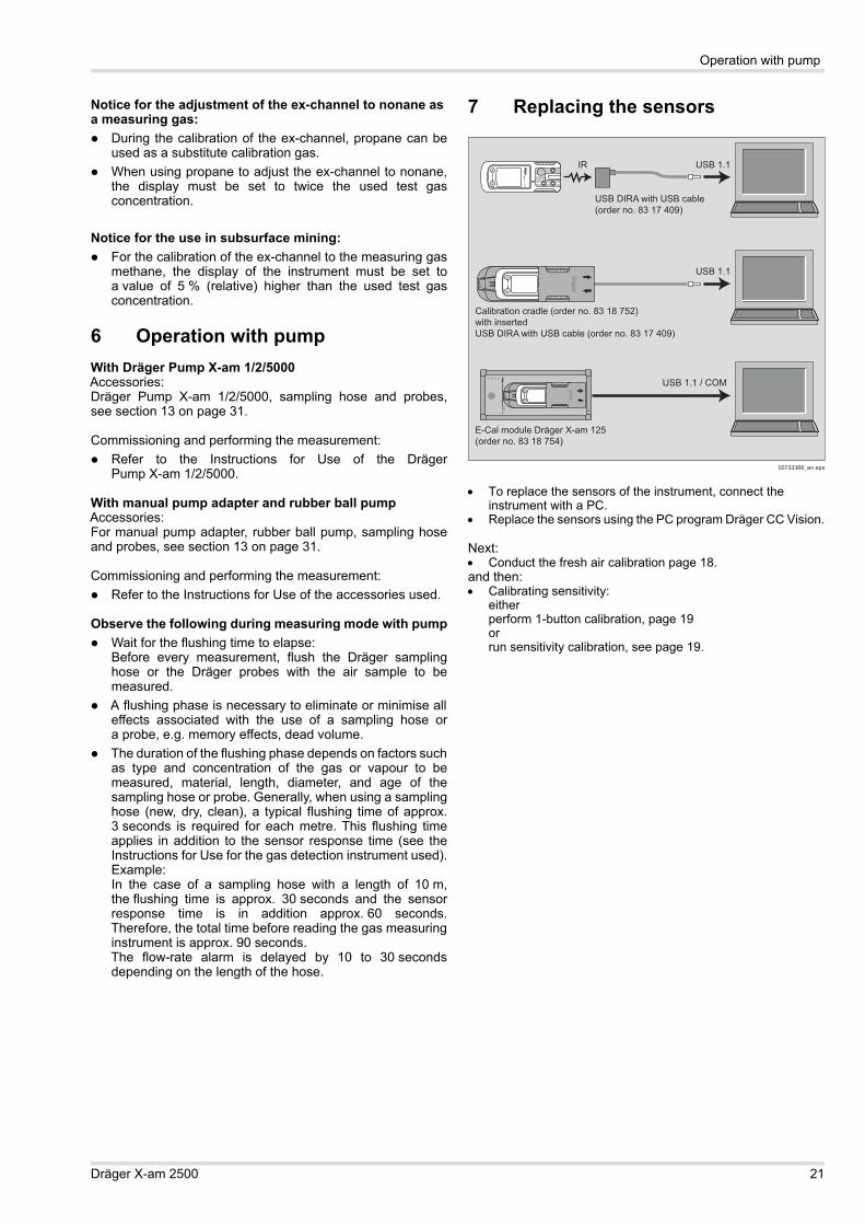
Calibration cradle (order no. 83 18 752)with insertedUSB DIRA with USB cable (order no. 83 17 409)
USB DIRA with USB cable(order no. 83 17 409)
E-Cal module Dräger X-am 125(order no. 83 18 754)
USB 1.1
USB 1.1
USB 1.1 / COM
00733366_en.eps
0
0
0X
-am 2500

Use
Dräger X-am 2500 13
Sensor settingsThe following changes can be made to the sensor parametersfor the sensors:
Testing the parametersIn order to ensure that the values have been correctlytransferred to the gas measuring device:1. Press the touch button Data from X-am 1/2/5x002. Check parameters.
3.3.4 Export data memory and display graphicallyTo read the database of the instrument and display itgraphically, the instrument must be connected with a PC.
The installed Dräger GasVision PC software is used forexporting and displaying the database. Observe the documentation and online help of the software.
3.4 Running the bump test
3.4.1 Manual implementation without documentation of the results in the instrument memory
1. Prepare a test gas cylinder,the volume flow must be0.5 l/min and the gasconcentration must behigher than the alarmthreshold concentrationthat is to be tested.Example test gas cylinder68 11 130 = mixed gas with50 ppm CO, 15 ppm H2S,2.5 vol. % CH4, 18 vol. % O2
2. Connect the test gascylinder with the calibrationcradle (order no. 83 18 752).
3. Vent the test gas intoa fume cupboard or into theopen air (with a hose connected to the second connector ofthe calibration cradle).
4. Switch on the instrument and insert it into the calibrationcradle – press downwards until it engages.
5. Open the test gas cylinder valve to let test gas flow overthe sensors.Recommendation: Wait until the instrument displays thetest gas concentration with sufficient tolerance –Ex: ±20 % of the test gas concentration1
O2: ±0.6 vol. %1
TOX: ±20 % of the test gas concentration 1
Wait until at least alarm threshold A1 or A2 has beenexceeded, however.If the alarm thresholds are exceeded, the instrumentdisplays the gas concentration in alternation with » A1 « or» A2 « depending on the test gas concentration.
6. Close the test gas cylinder valve and remove theinstrument from the calibration cradle.
If the concentration has now fallen under the A1 alarm threshold: Acknowledge the alarm.
If the displays are outside of the above-mentioned ranges: Calibrating/adjusting the instrument, see section 5 on
page 18.
Activate sensitivity calibration following negative bump test
Yes/No (relates only to a device connected to the Dräger Bump Test Station)
Bump test mode “extended bump test” or “quick bump test” or “bump test deactivated”
Warning after expiry of bump test interval
Yes/No
Error after expiry of bump test interval (if warning activated)
Yes/No
Bump test interval (days) 1 - 732Delay until error after expiry of cal. interval (days)
0 - 10
Activate user service life Yes/NoUser service life (days) (if activated)
0 - 999
Running in Yes/NoLEL category “---” or “PTB” or “IEC” or
“NIOSH” (if this is changed, the LEL factor will be altered to match)
1) At least one of the two operating signals must be switched on.2) Corresponds to the averaging time and is used to calculate the
exposure value TWA.3) Only evaluated if the sensor is provided for the purpose.4) Corresponds to the averaging time and is used to calculate the
exposure value STEL.
Designation FieldAlarm threshold A1 (in measurement unit)
0 - A2
Alarm threshold A2 (in measurement unit)
A1 – Measuring range limit value
Type of evaluation1
1) Only evaluated if the sensor is provided for the purpose.
Inactive, TWA, STEL, TWA+STEL
Alarm threshold STEL (in measurement unit)1)
0 – Measuring range limit value
Alarm threshold TWA (in measurement unit)1)
0 – Measuring range limit value
Calibration interval (days) 0 - 180 (sensor-dependent)Unit (sensor-dependent) Vol%, %UEG, %LEL, %LIE,
ppm, mbar, ppb, mg/m3
Gas name: “Ex” (CatEx sensor only)
Yes/No
CAUTIONNever inhale the test gas. Health hazard! Observe thehazard warnings of the relevant Safety Data Sheets.
1 Upon application of the Dräger mixed gas (order no. 68 11 130) the displays should be within this range.
00833366.eps
0,5 L/min
0
!

14 Dräger X-am 2500
Use
3.4.2 Menu implementation with the documentation of results in the instrument memory
The setting to "Quick bump test" or "Extended bump test" ismade using the PC software Dräger CC Vision.In the "Quick bump test" a check is carried out as to whetheror not the gas concentration has exceeded alarm threshold 1(with oxygen, the test checks that alarm threshold 1 has notbeen reached).In the case of the “Extended bump test”, a check is made as towhether the gas concentration has reached the set bump testconcentration within a tolerance window.
Setting on delivery: Extended bump test.1. Prepare a test gas cylinder, the volume flow must be 0.5 l/min
and the gas concentration must be higher than the alarmthreshold concentration that is to be tested.Example test gas cylinder 68 11 130 = mixed gas with50 ppm CO, 15 ppm H2S, 2.5 vol. % CH4, 18 vol. % O2
2. Connect the test gas cylinderwith the calibration cradle(order no. 83 18 752)).
3. Vent the test gas into a fumecupboard or into the openair (with a hose connectedto the second connector ofthe calibration cradle).
4. Switch on the instrument and insert it into the calibrationcradle – press downwards until it engages.
5. Open the Quick menu andselect the bump test,page 17.The current gasconcentration values andthe special symbol » «(for bump test) flash.
6. Press the key to startthe bump test.
7. Open the test gas cylindervalve to let test gas flowover the sensor.
If gas concentration exceeds the alarm thresholds A 1 or A 2 the corresponding alarm will occur.
Ending the bump test:After the set bump testconcentration has beenreached or a gas alarm hasbeen triggered (with "Quickbump test"): The display containing the
current gas concentrationchanges with the display» OK «.
The bump test that wascarried out is documentedwith the result and date inthe instrument memory.
8. Close the test gas cylindervalve and remove theinstrument from the calibration cradle.
If the concentration values have now fallen under the A1alarm thresholds, the instrument returns to the measuringmode.
If the set bump test concentration is not reached within theset time, an error is issued. The fault message
» « appears and» « is displayedinstead of the measuredvalue on the faultymeasuring channel.
In this case, repeat thebump test or calibratethe instrument, page 21.
The bump test can also be run automatically. The "Bump TestStation" is required for this function, see section 3.4.3 onpage 14.
3.4.3 Automatic implementation with the Bump Test Station
Prerequisite:The instrument first needs to be configured for the automaticbump test using the Dräger CC-Vision PC sofware. Activating the instrument for the automatic bump test. Composition of test gas (mixed gas) – standard on delivery:
50 ppm CO, 15 ppm H2S, 2.5 vol. % CH4, 18 vol. % O2
CAUTIONNever inhale the test gas. Health hazard! Observe thehazard warnings of the relevant Safety Data Sheets.
00833366.eps
0,5 L/min
0
!
00933366_en.eps
CH4%LELO2Vol%COppmH2SppmOK
01033366_en.eps
CH4%LELO2Vol%COppmH2Sppm
01133366_en.eps
CH4
%LELO2Vol%COppmH2Sppm
01333366.eps
0
Ex%UEGO2Vol%COppmH2Sppm

Use
Dräger X-am 2500 15
Define which measuring channels should participate in theautomatic bump test. All measuring channels participate inthe bump test by default.
1. Prepare the Bump Test Station according to the instructions.2. Switch on the instrument
and insert it into thereceptacle of the Bump TestStation until it engages.The bump test will bestarted automatically.The special symbol » «(for bump test) flashes.
If a gas alarm (quick bumptest) is initiated and the set bump test concentration(Accelerated bump test) is reached within the set time, thecurrent gas concentration will be displayed alternately with» OK «.
3. Remove the instrument from the Bump Test Station. If the concentration values have now fallen under the A1
alarm thresholds, the instrument returns to the measuringmode.
If there is no alarm during the bump test and the currentmeasurements do not reach the set target concentration("Accelerated bump test" only), an error is issued. The fault message
» « appears and» « is displayedinstead of the measuredvalue on the faultymeasuring channel.
In this case, repeat thebump test or calibratethe instrument, page 21.
The bump test can also be run manually, see section 3.4.1 onpage 13.
The Dräger CC Vision PC software can be used to enable the"Automatic calibration after incorrect bump test" option.
3.5 During operation During operation, the measured values for every measured
gas are displayed. If a measuring range is exceeded or not reached,
the following displays are shown instead of the measuredvalue display:
Excess concentrations of flammable materials can lead toa lack of oxygen.
For O2 concentrations under 8 vol. % an error is indicatedwith » « at the ex-channel instead of the measuringvalue as long as the measuring value falls below the pre-warning threshold.
In the event of an alarm, the corresponding displays,including the visual, audible and vibration alarms,are activated, see section 6 on page 21.
If the measuring range is exceeded significantly at the CatExchannel (very high concentration of flammable materials),a blocking alarm is triggered. This CatEx blocking alarm canbe acknowledged manually by switching the instrument off andback on again in fresh air.
After the measuring range of the TOX measuring channels hasbeen exceeded temporarily (up to one hour), checking themeasuring channels is not necessary.
3.6 Identifying alarmsAn alarm is displayed visually, audibly and through vibration ina specific pattern.
3.6.1 Concentration pre-alarm A1
The pre-alarm A1 is not latching and stops when theconcentration has dropped below the alarm threshold A1. In case of A1, a single tone is audible and the alarm
LED flashes.
Acknowledging the pre-alarm: Press the key. Only the audible alarm and the vibration
alarm are switched off.
01133366_en.eps
CH4
%LELO2Vol%COppmH2Sppm
01133366_en.eps
CH4
%LELO2Vol%COppmH2Sppm
» « (measuring range exceeded) or
» «(measuring range not reached) or
» «
(blocking alarm).
NOTICESpecial states in which there is no measuringoperation (quick menu, calibration menu, warm-up ofsensors, password input) are indicated by a visualsignal (slow flashing of the alarm LED
).
WARNINGIn the event of an impact load when using a CatExsensor in the Dräger X-am 2500 that causes the freshair display to deviate from zero, the zero point andsensitivity must adjusted.
Intermittent alarm:Display » A1 « and measured value alternating:
ii
!
OK

16 Dräger X-am 2500
Use
3.6.2 Concentration main alarm A2
In case of A2, a double tone is audible and the alarmLED flashes twice.
After leaving the area, when the concentration has droppedbelow the alarm threshold: Press the key. The alarm messages are switched off.
If the measuring range is exceeded significantly on the CatExchannel (very high concentration of flammable materials), ablocking alarm is triggered. This CatEx blocking alarm can beacknowledged manually by switching the instrument off andback on again in fresh air.
3.6.3 STEL / TWA exposure alarm
The STEL and TWA alarm cannot be acknowledgedor cancelled.
Switch off the instrument. The values for the exposureevaluation are deleted after the instrument is switchedon again.
3.6.4 Battery pre-alarm
Acknowledging the pre-alarm: Press the key. Only the audible alarm and the vibration
alarm are switched off. The battery still lasts min. 20 minutes after the first battery
pre-alarm.
3.6.5 Battery main alarm
The battery main alarm cannot be acknowledged or cancelled: The device automatically switches off after 10 seconds. Before the instrument is switched off, the visual, audible
and vibration alarms are activated for a short time.
3.6.6 Instrument alarm
The instrument is not ready for operation. For corrective measures, see“Replacing the sensors” on
page 21 to page 24. Contact maintenance or Draeger Service to rectify
the problem.
WARNINGRisk of fatal injury! Leave the area immediately. A mainalarm is self-latching and cannot be acknowledged orcancelled.
Intermittent alarm:Display » A2 and measured value alternating:
WARNINGLeave the area immediately. After this alarm,the deployment of personnel is subject to the relevantnational regulations.
Intermittent alarm:Display » A2 « and » « (STEL) or » « (TWA) and measured value alternating:
Intermittent alarm:Flashing special symbol » « on the right side of the display:
Intermittent alarm:Flashing special symbol » « on the right side of the display:
!
OK
!
OK
Intermittent alarm:Special symbol » « displayed on the right side of the display:

Menu functions
Dräger X-am 2500 17
4 Menu functions
4.1 Activating the Info mode In measuring mode, press the key for approx. 3 seconds. If any warning or fault messages exist, the corresponding
information or error codes will be displayed (see section 8on page 22).
Press the key successively for the next display. The peak values and the exposition values TWA1 and
STEL1) are displayed.
If no key is pressed for 10 seconds, the instrument returnsautomatically to measuring mode.
4.2 Opening Info-Off Mode When the instrument is in a deactivated state, press the
key.The name of the gas, measuring unit, and measuring rangelimit value are displayed for all channels.
Pressing the key again exits the Info Off mode(or via timeout).
4.3 Quick Menu
4.3.1 Quick menu functions
4.3.2 Opening the Quick MenuOn delivery, only the fresh air calibration is activated in theQuick Menu. The PC software Dräger CC Vision can be used
to activate the bump test for the quick menu and/or the functionfor displaying and deleting peak values.1. In measuring mode, press the key three times.
If no functions have been activated in the quick menu,the instrument remains in measuring mode.
2. You can select the activated functions of the quick menu bypressing the key. Press the key to call the selected function. Press the key to cancel the active function and to
switch to measuring mode. If no key is pressed for 60 seconds, the instrument
returns automatically to measuring mode.
4.3.3 Quick menu "Delete peak values"After the function has beenselected, the current peakvalues are displayed; the peakvalues special symbol appearsin the display at the same time.
1. The peak values can bedeleted by pressing the
key for 5 sec. and theadjacent display appears,for example.
2. Press the key to endthe function.
4.4 Calibration Menu
4.4.1 Calibration menu functions
4.4.2 Open the Calibration Menu The calibration menu can only be accessed by entering
a password.Password on delivery: » 001 «
The default password on delivery can be changed usingthe PC software Dräger CCVision.
1 Only when activated in the instrument configuration. Delivery status: not activated.
Warning messages are displayed. Numerical codesof warning messages: see section 8.1 on page 22. keyFault messages are displayed. Numerical codes offault messages: see section 8.2 on page 24. keyThe peak values = the maximum measured values inthe case of, e.g., CO, H2S, ... or the minimummeasured values in the case of O2 within the storageinterval are displayed keyThe average values of the exposures based on a shiftof, e.g., 8 hours (TWA) of all the active sensors for theexposure evaluation are displayed keyThe short-term values (STEL) = average values ofthe concentrations over the average value durationof all the active sensors for the exposure evaluationare displayed keyThe instrument is in measuring mode again
Bump test see section 3.4 on page 13
Fresh air calibration, see section 5.2 on page 18
Delete peak values, see section 4.3.3 on page 17
OK
OK
OK
OK
OK
OK
OK
OKFresh air calibration, see section 5.2 on page 18
1-button calibration, see section 5.3 on page 19
Single gas calibration, see section 5.3.1 on page 19
OK
00433366_en.eps
CH4%LELO2Vol%COppmH2Sppm
00533366_en.eps
CH4%LELO2Vol%COppmH2Sppm
OK
OK

18 Dräger X-am 2500
Calibrate instrument
1. In measuring mode, press the key for at least 4 seconds.The function for entering the password is selected.The special symbol » « (for the "enter password" function)is displayed.The display shows » 000 «,with the first digit flashing.
2. Use the key to set theflashing digit.
3. Press the key, thesecond digit starts flashing.
4. Use the key to set theflashing digit.
5. Press the key, the thirddigit starts flashing.
6. Use the key to set theflashing digit.
7. Press the key to confirmthe password once it hasbeen set completely.
8. The calibration menu functions can now be selected bypressing the key. Press the key to call the selected function. Press the key to cancel the active function. If no key is pressed for 10 minutes, the instrument
automatically returns to measuring mode.
5 Calibrate instrument
Adjustment may not be possible due to instrument andchannel errors.
Allow the sensors to warm up before the calibration! Warming-up time: see instructions for use / data sheets for
the Dräger sensors installed (product page for X-am 2500at www.draeger.com).
5.1 Adjustment interval: Observe the relevant specifications in the Instructions for
Use/data sheets of the Dräger Sensors installed. For critical applications, observe the recommendations in
EN 60079-29-21 or EN 45544-42 and national regulations.We recommend that you adjust all the channels after6 months.
Improving the zero point accuracy – perform fresh aircalibration, page 18.
Set the sensitivity of all sensors to the value of thetest gas – carry out the 1-button calibration, page 19.
Set the sensitivity of a sensor to the value of the test gas –span calibration/adjustment, page 19.
5.2 Run fresh air calibrationTo improve the zero-point accuracy, a fresh air calibration canbe carried out. Calibrate the instrument to fresh air, free of measured
gases or other interfering gases. Sensors which have not warmed up or which are faulty
prevent a calibration. In the case of sensors which are in the warm-up phase,
the message » 159 « is displayed with the specialsymbol » « (for warning message).
In the case of a sensor or instrument error,the message » 109 « is displayed with the specialsymbol » « (for a fault message).
The message is cleared after 5 seconds and thefunction is available again in the menu.
During the fresh air calibration the zero point of all sensors(with the exception of the DrägerSensor XXS O2) are setto 0.
In the case of the DrägerSensor XXS O2, the display is setto 20.9 vol. %.
1. Switch on instrument.2. Depending on instrument configuration:
Open the Quick menu and select the fresh aircalibration function, page 17.
or Open the Calibration menu and select the fresh air
calibration function, page 17. The current gas concentra-
tion values flash. When the measured values
have stabilized:3. Press the key to carry
out the fresh air calibration.
The display containing thecurrent gas concentrationchanges with the display» OK «.
4. Press the key to confirmthe calibration or wait forapprox. 5 seconds.
WARNINGAlways calibrate the zero-point before span.Otherwise, the calibration will contain errors!
1 EN60079-29-2 – Guidelines for selection, installation, use and maintenance of instruments for the detection and measurement of flammable gases and oxygen.
2 EN 45544-4 – Electrical instruments for the direct detection and direct concentration measurement of toxic gases and vapours – Part 4: Guide for selection, installation, use and maintenance.
CAUTIONNever inhale the test gas. Health hazard! Observe thehazard warnings of the relevant Safety Data Sheets.
00633366.eps
OK
OK
OK
OK
!
!01333366_en.eps
CH4
%LELO2Vol%COppmH2Sppm
OK
01433366_en.eps
CH4%LELO2Vol%COppmH2Sppm
OK

Calibrate instrument
Dräger X-am 2500 19
If a fault has occurred during the fresh air calibration: The fault message » «
appears and » « isdisplayed for the respectivesensor instead of themeasured value.
In this case, repeat thefresh air calibration.
Replace the sensor ifnecessary, page 21.
5.3 1-button calibration
All sensors approved by the Dräger CC-Vision PC programare included in the 1-button calibration.
In the case of the 1-button calibration, the sensitivity of allsensors is set to the value of the test gas.When using test gas cylinder 68 11 130 = mixed gas with50 ppm CO, 15 ppm H2S, 2.5 vol. % CH4, 18 vol. % O2.
If a mixed gas with anothercomposition is used,the specified concentrationvalues in the instrumentmust be changed to thetarget values of the mixedgas used using the PCsoftware "Dräger CC-Vision".
1. Connect the test gascylinder with the calibrationcradle.
2. Vent the test gas into a fumecupboard or into the openair (with a hose connectedto the second connector of the calibration cradle).
3. Switch on the instrumentand insert it into thecalibration cradle until itengages.
4. Call the calibration menu,enter the password and se-lect the 1-button calibrationfunction, page 17.
5. Press the key to startthe 1-button calibration.
6. Open the test gas cylindervalve to let test gas flowover the sensor.The currently displayedmeasured values startto flash.The flashing stops after a static measured value hasbeen reached.The calibration is now carried out automatically.The displayed measured values change to the valuesaccording to the gas supplied.
7. The automatic stability monitoring can be overridden bypressing the key. A calibration is carried out immediately.If it is detected that no test gas has been supplied,the 1-button calibration is cancelled. The channels thendisplay » n/a «. If only one sensor is included in the 1-buttoncalibration, an adjustment is carried out in any case whenthe key is pressed.
When the calibration is completed and the displayedmeasured values have stabilised: The display containing the
current gas concentrationchanges with the display» OK «.
8. Press the key or waitfor 5 seconds to quit thecalibration.
The instrument changes tothe measuring mode
9. Close the test gas cylindervalve and remove theinstrument from thecalibration cradle.
If a fault occurs during the 1-button calibration: The fault message » «
appears and » « isdisplayed for the respectivesensor instead of themeasured value.
In this case, repeatthe 1-button calibration orcarry out a single gascalibration, see section5.3.1 on page 19.
Replace the sensor ifnecessary, page 21.
5.3.1 Calibrating the sensitivity for an individual measuring channel
The span calibration can be carried out specifically forindividual sensors.
NOTICEIf no sensors have been approved by the DrägerCC-Vision PC program for the 1 button calibration,the 1-button calibration will not be available.
CAUTIONNever inhale the test gas. Health hazard! Observe thehazard warnings of the relevant Safety Data Sheets.
01533366_en.eps
CH4%LELO2Vol%COppmH2Sppm
ii
00833366.eps
0,5 L/min
0
!
01633366_en.eps
CH4%LELO2Vol%COppmH2Sppm
OK
OK
OK
01733366_en.eps
CH4%LELO2Vol%COppmH2Sppm
OK
01833366_en.eps
CH4%LELO2Vol%COppmH2Sppm
20 Dräger X-am 2500
Calibrate instrument
In the case of the span calibration, the sensitivity of theselected sensor is set to the value of the test gas used.
Use a standard test gas.Allowed test gas concen-tration:
1. Connect the test gascylinder with the calibrationcradle.
2. Vent the test gas into a fume cupboard or into the open air(with a hose connected to the second connector of thecalibration cradle).
3. Switch on the instrument and insert it into the calibrationcradle.
4. Press the [ + ] key and keep it pressed for 5 seconds toopen the calibration menu, enter the password and selectthe single gas calibration function, page 17.
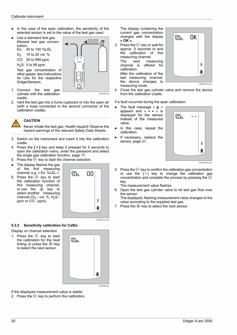
5. Press the key to start the channel selection. The display flashes the gas
of the first measuringchannel, e.g. » Ex %LEL «.
6. Press the key to startthe calibration function ofthis measuring channel,or use the key toselect another measuringchannel (O2 - vol. %, H2S -ppm or CO - ppm).
5.3.2 Sensitivity calibration for CatExDisplay on channel selection:1. Press the key to start
the calibration for the heattinting or press the -keyto select the next sensor.
If the displayed measurement value is stable:2. Press the key to perform the calibration.
The display containing thecurrent gas concentrationchanges with the display» OK «.
3. Press the key or wait forapprox. 5 seconds to endthe calibration of thismeasuring channel.The next measuringchannel is offered forcalibration.After the calibration of thelast measuring channel,the device changes tomeasuring mode.
4. Close the test gas cylinder valve and remove the devicefrom the calibration cradle.
If a fault occurred during the span calibration. The fault message » «
appears and » « isdisplayed for the sensorinstead of the measuredvalue.
In this case, repeat thecalibration.
If necessary, replace thesensor, page 21.
5. Press the key to confirm the calibration gas concentrationor use the [ + ] key to change the calibration gasconcentration and complete the process by pressing the key.The measurement value flashes.
6. Open the test gas cylinder valve to let test gas flow overthe sensor.The displayed, flashing measurement value changes to thevalue according to the supplied test gas.
7. Press the -key to select the next sensor.
Ex: 40 to 100 %LELO2 10 to 25 vol. %CO: 20 to 999 ppmH2S: 5 to 99 ppmTest gas concentration ofother gases: see Instructionsfor Use for the respectiveDrägerSensors.
CAUTIONNever inhale the test gas. Health hazard! Observe thehazard warnings of the relevant Safety Data Sheets.
00833366.eps
0,5 L/min
0
!
OK
01933366_en.eps
CH4%LELCO2ppmO2Vol%COppmH2SppmNH3ppm
OK
02033366.eps
ch4%LELCO2ppmO2Vol%COppmH2SppmNH3ppm
OK
OK
02433366_en.eps
CH4%LEL
OK
02533366_en.eps
CH4%LELCO2ppmO2Vol%COppmH2SppmNH3ppm
OK
OK
Operation with pump
Dräger X-am 2500 21
Notice for the adjustment of the ex-channel to nonane as a measuring gas: During the calibration of the ex-channel, propane can be
used as a substitute calibration gas. When using propane to adjust the ex-channel to nonane,
the display must be set to twice the used test gasconcentration.
Notice for the use in subsurface mining: For the calibration of the ex-channel to the measuring gas
methane, the display of the instrument must be set toa value of 5 % (relative) higher than the used test gasconcentration.
6 Operation with pumpWith Dräger Pump X-am 1/2/5000Accessories:Dräger Pump X-am 1/2/5000, sampling hose and probes,see section 13 on page 31.
Commissioning and performing the measurement: Refer to the Instructions for Use of the Dräger
Pump X-am 1/2/5000.
With manual pump adapter and rubber ball pumpAccessories:For manual pump adapter, rubber ball pump, sampling hoseand probes, see section 13 on page 31.
Commissioning and performing the measurement: Refer to the Instructions for Use of the accessories used.
Observe the following during measuring mode with pump Wait for the flushing time to elapse:
Before every measurement, flush the Dräger samplinghose or the Dräger probes with the air sample to bemeasured.
A flushing phase is necessary to eliminate or minimise alleffects associated with the use of a sampling hose ora probe, e.g. memory effects, dead volume.
The duration of the flushing phase depends on factors suchas type and concentration of the gas or vapour to bemeasured, material, length, diameter, and age of thesampling hose or probe. Generally, when using a samplinghose (new, dry, clean), a typical flushing time of approx.3 seconds is required for each metre. This flushing timeapplies in addition to the sensor response time (see theInstructions for Use for the gas detection instrument used).Example: In the case of a sampling hose with a length of 10 m,the flushing time is approx. 30 seconds and the sensorresponse time is in addition approx. 60 seconds.Therefore, the total time before reading the gas measuringinstrument is approx. 90 seconds.The flow-rate alarm is delayed by 10 to 30 secondsdepending on the length of the hose.
7 Replacing the sensors
To replace the sensors of the instrument, connect the instrument with a PC.
Replace the sensors using the PC program Dräger CC Vision.
Next: Conduct the fresh air calibration page 18.and then: Calibrating sensitivity:
eitherperform 1-button calibration, page 19orrun sensitivity calibration, see page 19.
IR
Calibration cradle (order no. 83 18 752)with insertedUSB DIRA with USB cable (order no. 83 17 409)
USB DIRA with USB cable(order no. 83 17 409)
E-Cal module Dräger X-am 125(order no. 83 18 754)
USB 1.1
USB 1.1
USB 1.1 / COM
00733366_en.eps
0
0
0X
-am 2500
22 Dräger X-am 2500
Troubleshooting
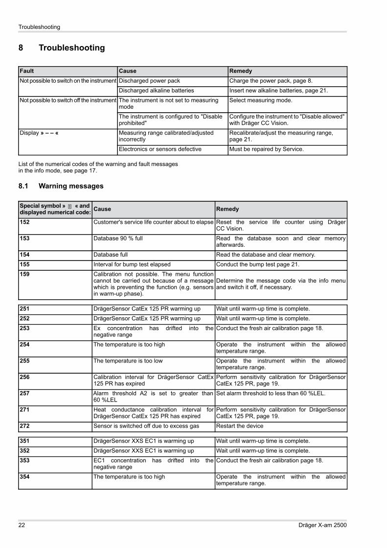
8 Troubleshooting
List of the numerical codes of the warning and fault messagesin the info mode, see page 17.
8.1 Warning messages
Fault Cause RemedyNot possible to switch on the instrument Discharged power pack Charge the power pack, page 8.
Discharged alkaline batteries Insert new alkaline batteries, page 21.
Not possible to switch off the instrument The instrument is not set to measuring mode
Select measuring mode.
The instrument is configured to "Disable prohibited"
Configure the instrument to "Disable allowed" with Dräger CC Vision.
Display » – – « Measuring range calibrated/adjusted incorrectly
Recalibrate/adjust the measuring range, page 21.
Electronics or sensors defective Must be repaired by Service.
Special symbol » « and displayed numerical code: Cause Remedy
152 Customer's service life counter about to elapse Reset the service life counter using DrägerCC Vision.
153 Database 90 % full Read the database soon and clear memoryafterwards.
154 Database full Read the database and clear memory.
155 Interval for bump test elapsed Conduct the bump test page 21.
159 Calibration not possible. The menu functioncannot be carried out because of a messagewhich is preventing the function (e.g. sensorsin warm-up phase).
Determine the message code via the info menuand switch it off, if necessary.
251 DrägerSensor CatEx 125 PR warming up Wait until warm-up time is complete.
252 DrägerSensor CatEx 125 PR warming up Wait until warm-up time is complete.
253 Ex concentration has drifted into thenegative range
Conduct the fresh air calibration page 18.
254 The temperature is too high Operate the instrument within the allowedtemperature range.
255 The temperature is too low Operate the instrument within the allowedtemperature range.
256 Calibration interval for DrägerSensor CatEx125 PR has expired
Perform sensitivity calibration for DrägerSensorCatEx 125 PR, page 19.
257 Alarm threshold A2 is set to greater than60 %LEL
Set alarm threshold to less than 60 %LEL.
271 Heat conductance calibration interval forDrägerSensor CatEx 125 PR has expired
Perform sensitivity calibration for DrägerSensorCatEx 125 PR, page 19.
272 Sensor is switched off due to excess gas Restart the device
351 DrägerSensor XXS EC1 is warming up Wait until warm-up time is complete.
352 DrägerSensor XXS EC1 is warming up Wait until warm-up time is complete.
353 EC1 concentration has drifted into thenegative range
Conduct the fresh air calibration page 18.
354 The temperature is too high Operate the instrument within the allowedtemperature range.

Troubleshooting
Dräger X-am 2500 23
355 The temperature is too low Operate the instrument within the allowedtemperature range.
356 The calibration interval for DrägerSensor XXSEC1 has elapsed
Run sensitivity calibration for DrägerSensorXXS EC1, page 19.
357 Alarm threshold A2 is set to greater than60 %LEL
Set alarm threshold to less than 60 %LEL.
451 DrägerSensor XXS EC2 in the warm-up phase Wait until warm-up time is complete.
452 DrägerSensor XXS EC2 in the warm-up phase Wait until warm-up time is complete.
453 EC2 concentration has drifted into thenegative range
Conduct the fresh air calibration page 18.
454 The temperature is too high Operate the instrument within the allowedtemperature range.
455 The temperature is too low Operate the instrument within the allowedtemperature range.
456 The calibration interval for DrägerSensorXXS EC2 has elapsed
Run sensitivity calibration for DrägerSensorXXS EC 3, page 19.
457 Alarm threshold A2 is set to greater than60 %LEL
Set alarm threshold to less than 60 %LEL.
551 DrägerSensor XXS EC3 in the warm-up phase Wait until warm-up time is complete.
552 DrägerSensor XXS EC3 in the warm-up phase Wait until warm-up time is complete.
553 EC3 concentration has drifted into thenegative range
Conduct the fresh air calibration page 18.
554 The temperature is too high Operate the instrument within the allowedtemperature range.
555 The temperature is too low Operate the instrument within the allowedtemperature range.
556 The calibration interval for DrägerSensorXXS EC3 has elapsed
Run sensitivity calibration for DrägerSensorXXS EC 3, page 19.
557 Alarm threshold A2 is set to greater than60 %LEL
Set alarm threshold to less than 60 %LEL.
575 Calibration interval for the compensationchannel has elapsed
Adjust the sensitivity of the compensation channel.
576 Calibration required because of overgassing. Adjust the sensitivity of the compensation channel.
651 DrägerSensor XXS EC 4 in the warm-up phase Wait until warm-up time is complete.
652 DrägerSensor XXS EC 4 in the warm-up phase Wait until warm-up time is complete.
653 EC 4 concentration has drifted into thenegative range
Conduct the fresh air calibration page 18.
654 The temperature is too high Operate the instrument within the allowedtemperature range.
655 The temperature is too low Operate the instrument within the allowedtemperature range.
656 The calibration interval for DrägerSensorXXS EC 4 has elapsed
Run sensitivity calibration for DrägerSensorXXS EC 4, page 19.
657 Alarm threshold A2 is set to greater than60 %LEL
Set alarm threshold to less than 60 %LEL.
Special symbol » « and displayed numerical code: Cause Remedy

24 Dräger X-am 2500
Troubleshooting
8.2 Fault message
Special symbol » « and displayed numerical code: Cause Remedy
102 The customer's service life counter has elapsed Reset the service life counter using DrägerCC Vision.
103 The instrument is defective The instrument must be repaired by Service.104 Check sum error program code The instrument must be repaired by Service.105 Bump test interval elapsed Run the bump test page 14.106 The calibration interval has elapsed (at least
1 calibration interval has elapsed)Run sensitivity calibration, see page 19 and/orpage 19.
107 Bump test error (at least 1 channel has a bumptest error)
Run bump test, page 14 or run sensitivitycalibration, page 19 and/or page 19.
108 The instrument is defective The instrument must be repaired by Service.109 The menu function cannot be carried out
because of an errorDetermine the error code via the info menu andswitch it off, if necessary.
111 Faulty alarm element test: Alarm light Repeat alarm element test using X-dock.112 Faulty alarm element test: Alarm horn Repeat alarm element test using X-dock.113 Faulty alarm element test: Vibration motor Repeat alarm element test using X-dock.114 Defective parameter check Correct parameters and repeat test using X-dock115 Instrument deactivated by X-dock Instrument activated using X-dock.116 Faulty software update The instrument must be repaired by Service.117 User parameters not feasible Check configuration of user parameters and adjust
201 No valid zero point calibration of theDrägerSensor CatEx 125 PR
Conduct the fresh air calibration page 18.
202 No valid sensitivity calibration of theDrägerSensor CatEx 125 PR
Run sensitivity calibration, see page 19 and/orpage 19.
203 Measurement from DrägerSensor CatEx125 PR is in negative range
Conduct the fresh air calibration page 18.
204 DrägerSensor CatEx 125 PR not plugged inor faulty
Check DrägerSensor CatEx 125 PR, page 21
205 Error during bump test of DrägerSensorCatEx 125 PR
Repeat bump test, where necessary, calibrate orreplace the DrägerSensor CatEx 125 PR, page 21.
207 Faulty rise time test Repeat rise time test using X-dock.208 User parameters not feasible Check configuration of user parameters and adjust218 Blocking alarm not plausible. Calibrate the sensor.221 Too little oxygen to operate the DrägerSensor
CatEx 125 PROperate sensor in an environment with at least8 vol. % O2.
222 No valid zero point calibration of theDrägerSensor CatEx 125 PR for heatconduction
Conduct the fresh air calibration page 18.
223 No valid sensitivity calibration of theDrägerSensor CatEx 125 PR for heatconduction
Run heat conduction sensitivity calibration,see page 19 and/or page 19.
224 Instrument incorrectly configured by DrägerCC-Vision.
Change sensor for applicable channel with DrägerCC-Vision.
301 No valid zero point calibration of the DrägerSensor XXS EC1
Conduct the fresh air calibration page 18.
302 No valid sensitivity calibration of the DrägerSensor XXS EC1
Run sensitivity calibration, see page 19 and/orfresh air calibration, page 18.
303 The measured value of DrägerSensor XXS EC1 is in the negative range
Conduct the fresh air calibration page 18.
304 DrägerSensor XXS EC1 is not inserted or faulty Check Dräger Sensor XXS EC1, page 21.

Troubleshooting
Dräger X-am 2500 25
305 Error in bump test of Dräger Sensor XXS EC1 Repeat bump test, calibrate or replaceDrägerSensor XXS EC1, if necessary page 21.
306 Faulty filter test Repeat filter test using X-dock.307 Faulty rise time test Repeat rise time test using X-dock.308 User parameters not feasible Check configuration of user parameters and adjust324 Instrument incorrectly configured by Dräger
CC-Vision.Change sensor for applicable channel with DrägerCC-Vision.
326 Error during warm-up acceleration DrägerSensor XXS EC1
Disconnect and reconnect power pack or replacethe sensor. Sensor must not be loaded with gaswithin the first 5 minutes.
401 No valid zero point calibration of the DrägerSensor XXS EC2
Conduct the fresh air calibration page 18.
402 No valid sensitivity calibration of the DrägerSensor XXS EC2
Run sensitivity calibration, page 19.
403 The measured value of DrägerSensor XXS EC2is in the negative range
Conduct the fresh air calibration page 18.
404 DrägerSensor XXS EC2 is not inserted or faulty Check Dräger Sensor XXS EC2, page 21.405 Error in bump test of Dräger Sensor XXS EC2 Repeat function test, calibrate or replace Dräger
Sensor XXS EC2, if necessary page 21.406 Faulty filter test Repeat filter test using X-dock.407 Faulty rise time test Repeat rise time test using X-dock.408 User parameters not feasible Check configuration of user parameters and adjust424 Instrument incorrectly configured by Dräger
CC-Vision.Change sensor for applicable channel with DrägerCC-Vision.
426 Error during warm-up acceleration DrägerSensor XXS EC2
Disconnect and reconnect power pack or replacethe sensor. Sensor must not be loaded with gaswithin the first 5 minutes.
501 No valid zero point calibration of the DrägerSensor XXS EC3
Conduct the fresh air calibration page 18.
502 No valid sensitivity calibration of the DrägerSensor XXS EC3
Run sensitivity calibration, page 19.
503 The measured value of DrägerSensor XXS EC3is in the negative range
Conduct the fresh air calibration page 18.
504 DrägerSensor XXS EC3 is not inserted or faulty Check Dräger Sensor XXS EC3, page 21.505 Error in bump test of Dräger Sensor XXS EC3 Repeat bump test, calibrate or replace
DrägerSensor XXS EC3, if necessary page 21.506 Faulty filter test Repeat filter test using X-dock.507 Faulty rise time test Repeat rise time test using X-dock.508 User parameters not feasible Check configuration of user parameters and adjust524 Instrument incorrectly configured by Dräger
CC-Vision.Change sensor for applicable channel with DrägerCC-Vision.
525 No valid sensitivity calibration for thecompensation channel
Carry out span calibration for compensationelectrode.
526 Error during warm-up acceleration DrägerSensor XXS EC3
Disconnect and reconnect power pack or replacethe sensor. Sensor must not be loaded with gaswithin the first 5 minutes.
601 No valid zero point calibration of the DrägerSensor XXS EC4
Conduct the fresh air calibration page 18.
602 No valid sensitivity calibration of the DrägerSensor XXS EC4
Run sensitivity calibration, page 19.
Special symbol » « and displayed numerical code: Cause Remedy

26 Dräger X-am 2500
Troubleshooting
603 The measured value of Dräger Sensor XXS EC4is in the negative range
Conduct the fresh air calibration page 18.
604 DrägerSensor XXS EC4 is not inserted or faulty Check Dräger Sensor XXS EC4, page 21.605 Error in bump test of Dräger Sensor XXS EC4 Repeat bump test, calibrate or replace
DrägerSensor XXS EC4, if necessary page 21.606 Faulty filter test Repeat filter test using X-dock.607 Faulty rise time test Repeat rise time test using X-dock.608 User parameters not feasible Check configuration of user parameters and adjust624 Instrument incorrectly configured by Dräger
CC-Vision.Change sensor for applicable channel with DrägerCC-Vision.
626 Error during warm-up acceleration DrägerSensor XXS EC4
Disconnect and reconnect power pack or replacethe sensor. Sensor must not be loaded with gaswithin the first 5 minutes.
Special symbol » « and displayed numerical code: Cause Remedy

Maintenance
Dräger X-am 2500 27
9 Maintenance
9.1 Maintenance tableThe instrument should be inspected and maintained by suitablyqualified persons annually. Consult: EN 60079-29-2 – Guide for the selection, installation, use
and maintenance of apparatus for the detection andmeasurement of combustible gases or oxygen
EN 45544-4 – Electrical apparatus used for the directdetection and direct concentration measurement of toxicgases and vapours - Part 4: Guide for selection,installation, use and maintenance
national regulations
Recommended calibration interval for measuring channels Ex,O2, H2S and CO: 6 months.
Depending on instrument configuration: Replace the alkaline batteries or charge the battery –
see section 3.1.2 on page 9 – after each use, at thelatest after the battery alarm has been triggered or after2 weeks.
Calibrating the instrument – see section 5 on page 18. At regular intervals, according to the sensors used and
the operating conditions. For sensor-specific calibrationdata, refer to the Instructions for Use/data sheets of thesensors used1.
Before you carry out safety-related relevantmeasurements, the zero point and sensitivity of theinstruments should be tested in accordance withnational regulations.
Inspection by suitably qualified persons – every year. The inspection intervals must be established in each
individual case and shortened if necessary, depending ontechnical safety considerations, engineering conditions,and the technical requirements of the equipment.
We recommend that a service agreement be concludedwith Dräger and that repairs also be carried out by them.
Replace the sensors, page 21 – if necessary, when it is notpossible to calibrate the sensors any more.
9.2 Cleaning
The instrument does not need any special care. Dirt and deposits can be removed from the instrument by
washing it with cold water. A sponge can be used for wipingif necessary.
Carefully dry the instrument with a cloth.
10 Storage Dräger recommends storing the instrument in the charger
module (order no. 83 18 639). Dräger recommends checking the charge of the power
supply at least every three weeks if the instrument is notstored in the charger module.
11 DisposalDispose of product in accordance to applicable regulations.
11.1 WEEE
11.2 Battery disposal
11.3 Electrochemical sensors
NOTICECalibration intervals of other gases: see Instructionsfor Use of the respective DrägerSensors.
1 Instructions for use/data sheets for the Dräger sensors can be downloaded from the product page for the X-am 2500 on the following website: www.draeger.com. See also the enclosed instructions for use and data sheets for the sensors used.
CAUTIONAbrasive cleaning implements (brushes etc.), cleaningagents and cleaning solvents can destroy the dust andwater filters.
ii
!
In accordance with EU Directive 2002/96/EC thisproductmust not be disposed of as household waste. This isindicated by with the adjacent icon.You can return this product to Dräger free of charge.For information please contact the national marketingorganisations and Dräger.
In accordance with EU Directive 2006/66/EC, batteriesand rechargeable batteries must not be disposed of ashousehold waste but must be taken to batterycollection centres. This is indicated by the adjacent icon.Collect batteries and rechargeable batteries asspecified by the applicable regulations and dispose ofat battery collection centres.
WARNINGAcid burn risk!Do not throw into fire or open with force.
As with batteries, dispose of as special waste in line withlocal waste disposal regulations. Further informationcan be obtained from the relevant local authority andfrom appropriate waste disposal companies.
The DrägerSensor CatEx 125 PR should be disposedof as electronics waste.
!

28 Dräger X-am 2500
Technical data
12 Technical data
12.1 X-am 2500Ambient conditions:during operation and storage –20 to +50 °C for NiMH power pack type: HBT 0000 and HBT 0100,
and for alkaline single cell type: Duracell Procell MN 15001
–20 to +40 °C for NiMH single cell type: GP 180AAHC1 and for alkaline single cell type: Panasonic LR6 Powerline0 to +40 °C for alkaline single cell type: Varta 40061, Varta 41061
700 to 1300 hPa10 to 90 % (short-term up to 95 %) relative humidity
Storage timeX-am 5000Sensors
1 year1 year
Position of use any
Instrument dataProtection class IP 67 for instruments with sensors
Alarm volume Typically 90 dB (A) at 30 cm distance
Operating time:Alkaline battery Typically 12 hours under normal conditions
NiMH power pack:T4 (type HBT 0000)T4 HC (type HBT 0100)
Typically 12 hours under normal conditionsTypically 13 hours under normal conditions
Dimensions approx. 130 mm x 48 mm x 44 mm (H x W x D)
Weight approx. 220 g to 250 g
Refresh interval for display andsignals
1 s
1) Not subject to BVS10 ATEX E 080X and PFG 10 G 001X performance approval.

Technical data
Dräger X-am 2500 29
12.2 Sensor dataExtract! For details, see the data sheets for the sensors used (Instructions for use/data sheets for the Dräger sensors can bedownloaded from the product page for the X-am 2500 on the following website: www.draeger.com)
.Ex XXS O2 XXS H2S-LC XXS CO
Measuring principle Catalytic oxidation Electrochemical Electrochemical Electrochemical
Measurement value configurationtime t0..0.90
≤17 seconds for methane≤25 seconds for propane
≤10 seconds ≤18 seconds ≤25 seconds
Measurement value configurationtime t0...50
≤7 seconds for methane≤40 seconds for nonane 1
≤6 seconds ≤6 seconds ≤6 seconds
Measuring range 0 to 100 %LEL 20 to 5 vol. % for methane
0 to 25 vol. % 0 to 100 ppm H2S 3 0 to 2000 ppm CO 4
Zero error (EN 45544) – – – – – – 0.4 ppm 6 ppm
Instrument drift – – – – – – ≤1 % of measured value/month
≤1 % of measured value/month
Warm-up time 35 seconds ≤5 minutes ≤5 minutes ≤5 minutes
Effect of sensor poisonsHydrogen sulphide H2S,10 ppm
Halogenated hydrocarbons, heavymetals, substances containingsilicone, sulphur or polymerisablesubstances
≤1 %LEL/8 hours
Poisoning possible
– – –
– – –
– – –
– – –
– – –
– – –
Linearity error ≤5 %LEL ≤0.3 vol. % 2 % of the measured value
3 % of the measured value
Standards(Measuring function for explosion protection and measurement of oxygen deficiency and surplus as well as toxic gases, DEKRA EXAM GmbH, Essen, Germany: BVS 10 ATEX E 080X 2), PFG 10 G 001X
EN 60079-29-1 5EN 50271
EN 50104 6(measurement of oxygen deficiency
and oxygen surplus)
EN 50271
EN 45544-1/-2 7EN 50271
EN 45544-1/-2 8EN 50271
Cross sensitivities 9 Fitted Fitted Fitted Fitted

30 Dräger X-am 2500
Technical data
XXS NO2 XXS SO2
Measuring principle Electrochemical Electrochemical
Measurement value configuration time t0..0.90
15 seconds 15 seconds
Measurement value configuration time t0...50
– – – – – –
Measuring range 0 to 50 ppm NO2 0 to 100 ppm SO2
Zero error 0.2 ppm 0.1 ppm
Instrument drift 2 % the measuring value/month
2 % the measuring value/month
Warm-up time 5 minutes 5 minutes
Effect of sensor poisonsHydrogen sulphide H2S, 10 ppm halogenated hydrocarbons, heavymetals, gases containing silicone, sulphur or polymerizable substances
– – – – – –
Linearity error 2 % of the measured value
2 % of the measured value
Standards(Measuring function for explosion protection and measurement of oxygen deficiency and surplus as well as toxic gases, DEKRA EXAM, Essen, Germany: BVS 10 ATEX E 080X 2), PFG 10 G 001X
– – – – – –
Cross sensitivities 8) Fitted Fitted
1) For decreasing concentrations, the adjustment time for nonane is about 50 seconds.2) For alkanes from methane to nonane, LEL-values in accordance with EN 60079-20-1. For flow speeds of 0 to 6 m/s the deviation of the display can be 5 - 10 %
of the measuring value. For an adjustment to propane, the deviation of the display in the range of 80 to 120 kPa can be up to 6 %LEL.3) Certified for 0.4 to 100 ppm4) Certified for 3 to 500 ppm5) The instrument responds to most combustible gases and vapours. The sensitivities differ depending on the type of gas. We recommend a calibration using the
target gas to be measured. For the range of alkanes, the sensitivity decreases from methane to nonane.6) The measuring signals may be negatively affected by ethane, ethene, ethyne, carbon dioxide and hydrogen.7) The measuring signals may be additively affected by sulphur dioxide, nitrogen dioxide and hydrogen, and negatively affected by chlorine.8) The measuring signals can be affected additively by acetylene, hydrogen and nitrogen monoxide.9) A table of the cross sensitivities is contained in the Instructions for Use or the data sheet of the respective sensor.

Order list
Dräger X-am 2500 31
13 Order listName and description Order no.
Dräger X-am 2500Unlimited 1 to 4 multi gas monitors with exchangeable sensors.With selectable special calibration.Standard calibration for the ex-sensor: methane.Including country-specific adjustable standard alarm thresholds.
Dräger X-am 2500 standard instrument:Dräger X-am 2500 Ex 83 23 910Dräger X-am 2500 Ex, O2 83 23 912Dräger X-am 2500 Ex, O2, H2S LC 83 23 914Dräger X-am 2500 Ex, O2, CO 83 23 916Dräger X-am 2500 Ex, O2, CO, H2S LC 83 23 918
Basic instrument with selectable special calibrations, including a calibration certificate
83 23 900
Power supply units:NiMH power pack T4 (type HBT 0000) 83 18 704NiMH power pack T4 HC (type HBT 0100) 83 22 244Battery holder ABT 0100 83 22 237Alkaline batteries T3 (2 pcs)1 83 22 239Alkaline batteries T4 (2 pcs)1 83 22 240Rechargeable battery and charging kit (contains NiMH power pack T4, charging module for Dräger X-am 1/2/5000 and plugin power pack)
83 18 785
Chargers:Charging module for Dräger X-am 1/2/5000 83 18 639Power pack with connecting cord (worldwide)for a maximum of 20 charging modules Dräger X-am 1/2/5000
83 15 805
Power pack (worldwide) for a maximum of 5 charging modules Dräger X-am 1/2/5000
83 16 994
Power pack (worldwide) for a maximum of 2 charging modules Dräger X-am 1/2/5000
83 15 635
Vehicle connecting line 12 V/24 Vfor Dräger X-am 1/2/5000 charging module
45 30 057
Vehicle installation setfor 1 Dräger X-am 1/2/5000 charging module
83 18 779
AccessoriesThe accessories are not included in BVS10 ATEX E 080X and PFG 10 G 001X.Pump accessories:Dräger Pump X-am 1/2/5000 83 19 400Case for Dräger Pump X-am 1/2/5000 83 19 385Rubber ball pump 68 01 933Manual pump adapter 83 19 195Dust and water filter 83 13 648
Extension hoses and probes:Measuring probe 0.5 m 64 08 238Measuring probe 1.5 m 64 08 239Plug-in telescopic probe 68 01 954Telescopic probe 100 with accessories 83 16 530Telescopic probe 150 stainless steel 83 16 533Tester 90 83 16 532Float probe with accessories 83 18 371Viton hose 12 03 150Hose 11 80 681Accessories for measured value acquisition and configuration:Dräger GasVision 83 14 034USB DIRA with USB cable (USB infrared adaptor for communication Dräger X-am 1/2/5000 – PC)
83 17 409
Calibration/adjustment accessories:Dräger X-dock, e.g. X-dock 5300 X-am 125 83 21 880Bump Test Station, including mixed gas cylinder 83 19 130E-Cal module Dräger X-am 1/2/5000 83 18 754Calibration cradle Dräger X-am 1/2/5000 83 18 752Mixed gas cylinder2.5 vol. % CH4, 18 vol. % O2, 15 ppm H2S, 50 ppm CO
68 11 130
Test gas cylinder propane, 0.9 vol. % C3H8 in air 68 11 118
On demand regulator 83 16 556Standard regulator 68 10 397Other accessories:Protective case for Dräger X-am 1/2/5X00 83 21 506Carrying bag 83 18 755Spare partsDrägerSensor CatEx 125 PR, 0 to 100 %LEL 68 12 950
DrägerSensor XXS O2, 0 to 25 vol. %2 68 10 881
DrägerSensor XXS CO, 0 to 2000 ppm1) 68 10 882
DrägerSensor XXS H2S LC, 0 to 100 ppm1) 68 10 883
DrägerSensor XXS NO2, 0 to 50 ppm 68 10 884
DrägerSensor XXS SO2, 0 to 100 ppm 68 10 885
1) Not subject to the Metrological Performance Test BVS10ATEXE080X and PFG10G001X.
2) Expected service life of the sensors: O2 and CO >5 years, CatEx > 3 years.
Name and description Order no.

32 Dräger X-am 2500
Declaration of conformity
14 Declaration of conformity


© Dräger Safety AG & Co. KGaARevalstraße 123560 Lübeck, GermanyTel +49 451 882 0Fax +49 451 882 20 80www.draeger.com
90 33 366 - TH 4638.205 en© Dräger Safety AG & Co. KGaAEdition 03 - August 2013 (Edition 01 - November 2012)Subject to alteration