Embed Size (px)
Citation preview

Effect of Process Parameters on Conversion and Selectivity for the
Synthesis of Dibenzyl Sulfide Using Hydrogen Sulfide and Solid
Reusable Tri-Phase Transfer Catalyst
Thesis submitted to
National Institute of Technology, Rourkela
for the award of the degree of
Master of Technology
by
Thadela Srinivas
(Roll No: 211CH1264)
Under the supervision of
Dr. Sujit Sen
DEPARTMENT OF CHEMICAL ENGINEERING
NATIONAL INSTITUTE OF TECHNOLOGY ROURKELA
ROURKELA – 769008, ODISHA, INDIA
MAY 2013

CERTIFICATE
This is to certify that the thesis entitled “Effect of Process Parameters on Conversion and
Selectivity for the Synthesis of Dibenzyl Sulfide Using Hydrogen Sulfide and Solid
Reusable Tri-Phase Transfer Catalyst”, submitted by Thadela Srinivas to National
Institute of Technology Rourkela, in fulfillment of the requirements of the degree of Master
of Technology in Chemical Engineering is a bonafide record of the research work carried out
by him, in the Department of Chemical Engineering, National Institute of Technology,
Rourkela under my supervision and guidance. Mr. Srinivas has worked on this topic from
July, 2012 until April, 2013 and the thesis, in my opinion, is worthy of consideration for the
award of the degree of “Master of Technology” in accordance with the regulations of this
Institute. The results embodied in the thesis have not been submitted to any other University
or Institute for the award of any degree or diploma.
Date: 24th May, 2013 Dr. Sujit Sen
Department of Chemical Engineering
National Institute of Technology
Rourkela-769008

iii
ACKNOWLEDGEMENTS
I wish to thank and express my heartfelt gratitude to my supervisor Dr.
Sujit Sen, Assistant Professor, Department of Chemical Engineering, National
Institute of Technology Rourkela in guiding me to this interesting research
work. I thank him for being for constantly motivating me through his valuable
counsel as well his excellent tips to build my research and writing skills. The
technical discussions with Dr. Sujit Sen were always very insightful and I will
always be grateful to him for all the knowledge he has shared with me.
I also take this opportunity to express my sincere thanks to Prof.
R.k.Singh, head of the Department of Chemical Engineering for making
available necessary laboratory and departmental facilities to complete this
research work. I am also grateful to other faculty members of the department
for their help whenever sought for.
I wish to convey my sincere gratitude to the Director, NIT-Rourkela for
providing me the opportunity to pursue my research in this Institute.
I express my sincere gratitude to Ms. Deepthi, Ms. Deba laxmi, Sri.
Suresh, Sri. Sujeevan, who helped me in early part of my research and fruitful
discussions as senior scholars. I am also thankful to all lab mates, Nagarjun and
Leena Patil for their time-to-time help, encouragement and creating an
excellence atmosphere both inside and outside the department.
I am obliged to all my friends Ms. Meenakshee Pandey, Mr. Sandeep, Mr.
Dhani, Mr. Prasanna, for their friendships and encouragements.
I wish to convey my sincere thanks to my family members and Ms.
Supriya for their highest degree of love and constant encouragement.
Thadela Srinivas

DECLARATION
I certify that
a. the work contained in this thesis is original and has been done by me under the
guidance of my supervisor.
b. the work has not been submitted to any other Institute for any degree or diploma.
c. I have followed the guidelines provided by the Institute and Department in preparing
the thesis.
d. I have conformed to the norms and guidelines given in the Ethical Code of Conduct of
the Institute.
e. whenever I have used materials (data, theoretical analysis, figures, and text) from
other sources, I have given due credit to them by citing them in the text of the thesis
and giving their details in the references. Further, I have taken permission from the
copyright owners of the sources, whenever necessary.
Signature of the student: ……............................................
Name of the Student : Thadela Srinivas

v
List of Figures
Figure No. Figure Caption Page No.
Figure 1.1 Structural formulas of different alkanolamines 12
Figure 1.2 Flow diagram for Amine Treating Process 13
Figure 1.3
Process flow diagram of sulfur recovery process unit 16
Figure 3.1 Schematic diagram for the absorption of H2S in MEA solution 36
Figure 3.2 Schematic diagram of the batch reactor assembly 37
Figure 4.1 Effect of speed of agitation on conversion of BC 44
Figure 4.2 Effect of speed of agitation on conversion of BC in 45
presence and absence of catalyst
Figure 4.3 Effect of temperature on BC conversion 46
Figure 4.4 Effect of temperature on DBS selectivity 47
Figure 4.5 Kinetic plot for the effect of temperature 48
Figure 4.6 Arrhenius plot for activation energy 48
Figure 4.7 Effect of catalyst quantity on BC conversion 50
Figure 4.8 Effect of catalyst quantity on DBS selectivity 50
Figure 4.9 Effect of initial sulfide concentration on BC conversion 51
Figure 4.10 Effect of initial sulfide concentration on DBS selectivity 52
Figure 4.11 Effect of MEA concentration on BC conversion 53
Figure 4.12 Effect of MEA concentration on DBS selectivity 54
Figure 4.13 Effect of concentration of BC on conversion of BC 55
Figure 4.14 Effect of concentration of BC on selectivity of DBS 56
Figure 4.15 Relationship between conversion of BC and selectivity of 57
DBS under different BC concentrations

vi
Figure 4.16 Concentration profile for a typical run 60
Figure 4.17 Effect of cycle number of reuse on catalytic activity 62
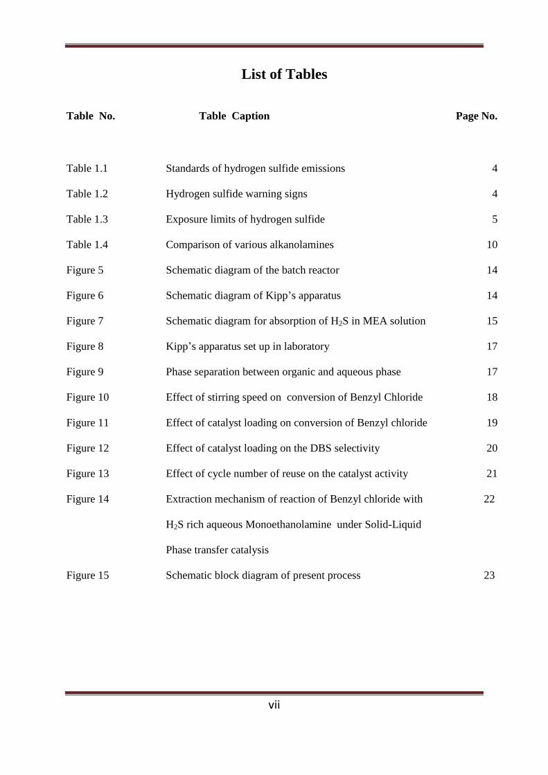
vii
List of Tables
Table No. Table Caption Page No.
Table 1.1 Standards of hydrogen sulfide emissions 4
Table 1.2 Hydrogen sulfide warning signs 4
Table 1.3 Exposure limits of hydrogen sulfide 5
Table 1.4 Comparison of various alkanolamines 10
Figure 5 Schematic diagram of the batch reactor 14
Figure 6 Schematic diagram of Kipp’s apparatus 14
Figure 7 Schematic diagram for absorption of H2S in MEA solution 15
Figure 8 Kipp’s apparatus set up in laboratory 17
Figure 9 Phase separation between organic and aqueous phase 17
Figure 10 Effect of stirring speed on conversion of Benzyl Chloride 18
Figure 11 Effect of catalyst loading on conversion of Benzyl chloride 19
Figure 12 Effect of catalyst loading on the DBS selectivity 20
Figure 13 Effect of cycle number of reuse on the catalyst activity 21
Figure 14 Extraction mechanism of reaction of Benzyl chloride with 22
H2S rich aqueous Monoethanolamine under Solid-Liquid
Phase transfer catalysis
Figure 15 Schematic block diagram of present process 23

viii
List of Abbreviations
BC Benzyl Chloride
BM Benzyl Mercaptan
DBS Dibenzyl Sulfide
DEA Diethanolamine
DIPA Diisopropanoloamine
GLC Gas Liquid Chromatography
MDEA Methyldiethanolamine
MEA Monoethanolamine
OVAT One variable at a time
ppm Parts per million
ppmv Parts per million by volume
PTC Phase Transfer Catalysis
TEA Triethanolamine
TPC Tri Phase Catalyst

Abstract
ix
Abstract
Hydrogen sulfide (H2S) is often found in the by-product gas-streams of many
petroleum and natural gas processing industries. Conventionally it is being used for the
production of elemental sulfur by Claus Process which is further utilized in the production of
sulfuric acid or rubber industries. But Claus process is an energy-expensive process as it
requires a high amount of energy and process control over oxygen and H2S ratio. H2S-laden
gas can be utilized well by absorbing into aqueous alkanolamine and then use this reagent as
a sulfiding agent to produce organo-sulfur compounds like thioether, mercaptans, disulfides
etc., which have higher usability and better market value. These organo-sulfide such as
Dibenzyl sulfide (DBS) find their application in pesticide, polymer, pharma and drug
industries. Since the alkanolamine and benzyl chloride are two different phases and to carry
out this triphasic reaction, phase-transfer-catalyst (PTC) has been used and often the
application of PTC gives enhancement in reaction rate, more conversion for reactants and
better selectivity of desired products.
This work was undertaken to study the synthesis of Dibenzyl Sulphide (DBS) and
Benzyl Mercaptan (BM) using H2S-rich monoethanolamine (MEA) and benzyl chloride (BC)
under Liquid-Liquid-Solid phase transfer catalysis with a tri-phase catalyst.Owing to its solid
state, availability, cost and reusability, Amberlite IR 400 is selected as a PTC. A parametric
study was carried out which emphasized upon the impact of catalyst loading as one of the
process variables on the conversion of benzyl chloride and selectivity of DBS and parametric
study with these substances revealed more that 90% selectivity for desired product at ambient
condition. The effects are utilized to establish a suitable mechanism of the reaction to explain
the course of the reaction.
The overall objective of this study is to maximize conversion of reactant BC,
maximize selectivity of desired product DBS. Reaction time, temperature, catalyst loading,
stirring speed, reactants concentration and solvent concentration were chosen as parameters.
These techniques can be used as an alternative to Claus process and also can act as a green
route for synthesizing value-added fine chemicals like DBS, Benzyl mercaptan (BM) etc.
Keywords: Hydrogen Sulfide; Alkanolamines; Dibenzyl sulfide; Benzyl mercaptan; Liquid-
Liquid-Solid Phase Transfer Catalysis; Mechanism; Selectivity; Conversion.

x
Contents
Title Page i
Certificate by the Supervisor ii
Acknowledgement iii
Declaration iv
List of Figures v
List of Tables vii
List of Abbreviations viii
Abstract ix
Contents x
Chapter 1 Introduction 1-26
1.1 Anthropogenic Routes to Hydrogen Sulfide 2
1.2 Requirement for Treating of H2S-laden gas 3
1.3 Industrial Processes for the Removal and
Reclamation of H2S
5
1.3.1 Ammonia-Based Processes 6
1.3.2 Alkanolamine-Based Process 8
1.4 Methods of Sulfur Retrieval of H2S 13
1.4.1 Claus process 13
1.4.2 CrystaSulf 17
1.4.3 Wet-Oxidation LO-CAT Process 17
1.5 Present work 18
1.6 Phase Transfer Catalysis 18
1.6.1 Interfacial Mechanism of PTC 21
1.6.2 Liquid-Liquid-Solid PTC 25
1.6.3 Mechanism of LLSPTC 26
Chapter 2 Literature Survey 27-33
2.1 Use of Aqueous Alkanolamines for the Removal
of H2S
28
2.2 Preparation of Benzyl Mercaptan 29
2.3 Preparation of Dibenzyl Sulfide 30
2.4 Use of Tri Phase Catalyst 32
2.5 Conclusion 33

xi
Chapter 3 Experimental 34-40
3.1 Chemicals and Catalyst 35
3.2 Preparation of H2S-Rich Aqueous alkanolamines 35
3.3 Apparatus and Equipment Setup 37
3.4 Reaction Procedure 38
3.5 Method of Analysis 38
3.5.1 Determination of Sulfide Concentration 38
3.5.2 Analysis of Organic Phase 40
Chapter 4 Reaction Of Benzyl Chloride with H2S-rich
Aqueous Monoethanolamine Under Liquid-Liquid-
Solid Phase Transfer Catalysis
41-62
4.1 Introduction 42
4.2 Results and Discussion 43
4.2.1 Parametric Study 43
4.2.1.1 Effect of Speed of Agitation 43
4.2.1.2 Effect of Temperature 45
4.2.1.3 Effect of Catalyst Quantity 49
4.2.1.4 Effect of initial MEA: Sulfide
mole ratio
51
4.2.1.5 Effect of concentration of BC 55
4.2.2 Mechanistic Investigation 58
4.2.3 Recycle and Reusability of Catalyst 61
Chapter 5 Summary and Conclusions 63-66
Chapter 6 Scope for further work 67-69
6.1 Investigation of Mechanistic Pathways 67
6.2 Finding out effect of other parameters 67
6.3 Use of Other Aqueous Phase 67
6.4 Exploring the possibilities of other value-added
products
69
6.7 Large-scale applications of the Present Process 70
References 70-78

CHAPTER 1
INTRODUCTION
Chapter 1: Introduction
2
Chapter 1
Introduction
Abstract
This chapter involves a broad overview of the present research work and its vitality. It
includes introduction to the sources of hydrogen sulfide, need to polish it off and retrieval.It
also envisages upon the conventional process used in the industries, the objectives of this
study and a note on the structure and organization of the thesis.
1.1. Anthropogenic Routes to Hydrogen Sulfide
About 10-12% of the total global discharges of the Hydrogen Sulfide (H2S) were
attributed by human deeds. H2S is found both naturally and from human-made industrial
processes. It is in the form of gases from volcanoes, sulfur springs, undersea vent, salt
marshes, swamps, and stagnant bodies of water and in the crude petroleum and natural gas.
The gas occurs naturally in coal pits, sulfur springs, gas wells, and as a product of decaying
sulfur-containing organic matter, particularly under low oxygen conditions. And is also
commonly come across in places such as municipal sewers, sewage treatment plants (H2S is
often called sewer gas), swine containment, manure stockpiles, manure-handling operations,
mines, hot springs, and the holds of fishing ships.
H2S may account for up to 1 % by volume of landfill gas emissions, although
typically the percentage is much less. The formation of hydrogen sulfide within a landfill
depends on certain conditions including moisture content, temperature, and pH; anaerobic
conditions (lacking oxygen); and a sulfate source.
Industrial sources of H2S comprise petroleum refineries, natural gas extraction plants,
petrochemical plants, coke oven plants, chemical manufacturing and waste disposal, pulp and
paper manufacturing (Kraft paper mills using the sulfate method), food processing plants,
rayon textile production, wastewater treatment plants and leather tanneries.
During the course of abundant processes in the petroleum, coal, and natural gas
processing industries, one or more gaseous by-products containing hydrogen sulfide H2S are
rather commonly produced. In industries, Hydrodesulfurization stands widely established

Chapter 1: Introduction
3
process used to remove sulfur (S) from natural gas and from refined petroleum products such
as gasoline or petrol, jet fuel, kerosene, diesel fuel, and fuel oils. By far the largest industrial
pavements to H2S occur in petroleum refineries. The supply of light and easy-to-process
crude oils are slowly deteriorating and the refiners throughout the world are forced to process
heavy crude containing high amount of sulfur and nitrogen. With strict environmental
guidelines and concerns, refiners are also forced to hydrotreat such crude to bring down the
sulfur and nitrogen concentrations to the agreed levels. During hydrotreatment of heavy and
sour crude, large amounts of H2S is formed. In addition, during the sequence of several
processes in the coal processing industries, one or more gaseous by-products containing H2S
is quite normally produced. The coal gas contains near about 0.3-3% H2S as the main non-
hydrocarbon impurities. Moreover, in the natural gas industry, the H2S content of certain gas
streams recovered from natural gas deposits in many areas of the world is often too high for
viable acceptance. The composition of raw natural gas diverges widely from field to field.
The H2S content may vary from 0.1 ppm to 150,000 ppm. Other anthropogenic sources of
hydrogen sulfide include coke ovens, paper mills (Kraft technique – using the sulfate
method), and tanneries.
Bacteria found in our mouth and gastrointestinal tract produce H2S during the
digestion of food containing vegetable or animal proteins.
1.2. Requirement for Treating of H2S-laden Gas
With an increase in the global environmental awareness, chemical industries are
facing severe complications with the dumping of environmentally hazardous materials like
H2Sin atolerable manner.The removal of H2S from gas and fluid streams is anticipated for a
variety of reasons, such as:
Hydrogen sulfide is a highly toxic and combustible gas with explosion limits ranging
from 4.3 - 46 %. Being heavier than air, it tends to agglomerate at the bottom of ill
ventilated places. Although very pungent at first, it quickly reduces the sense of smell, so
potential victims may be unconscious of its existence until it is too late. For safe
management procedures, a hydrogen sulfide material safety data sheet (MSDS) should be
consulted. Different standards of H2S emissions and its warning signs were shown in
Table 1.1. and Table 1.2. respectively

Chapter 1: Introduction
4
Table 1.1. Standards of H2S emissions
Occupational Exposure Limit (8 h time weighted average) 10 ppm
Public Exposure Limit (for the general population) 0.03-0.006 ppm
Maximum Emissions Limit from Sulfur Recovery Units
• 1500 ppmv of sulfur compounds calculated as SO2
• 10 ppmv of H2S.
• 200 pounds per hour of sulfur compounds calculated as SO2
Table 1.2: H2S Warning Signs
Concentration in parts per million
(ppm)
Observations and health effects
Less than 1 Most people smell “rotten eggs.”
3-5 Odor is strong.
20-150 Nose and throat feel dry and irritated. Eyes
sting, itch, or water; and “gas eye” symptoms may occur
150-200 Sense of smell is blocked (olfactory fatigue).
200-250 Major irritation of the nose, throat, and lungs occurs,
along with headache, nausea, vomiting, and dizziness.
Prolonged exposure can cause fluid buildup in the lungs
(pulmonary edema), which can be fatal.
300-500 Symptoms are the same as above, but more severe. Death
can occur within 1 to 4 hours of exposure. Above 500
Immediate loss of consciousness. Death is likely to be
immediate

Chapter 1: Introduction
5
The removal of H2S from fluid streams can be desirable for a variety of reasons, such as:
H2S is odiferous in nature, corrosive in the presence of water and poisonous in
very small concentrations. Therefore, it must almost completely be removed from the gas
streams before use and preferably before transport. As a result, many pipeline
specifications limit the amount of H2S to less than 0.25 g/100 ft3 of gas (Thomas, 1990).
The presence of H2S in the refinery gas streams can cause a number of detrimental
problems in subsequent processing steps such as corrosion of process equipment,
deterioration and deactivation of the catalysts, undesired side reactions, increase in the
process pressure requirements, increase in the gas compressor capacity, etc. (Hamblin,
1973).
Table 1.3 Exposure Limits of H2S (US Department of Labor)
Occupational Health and Safety Administration (OSHA) Permissible
Exposure limit (PEL) for general industry
10 ppm
American Conference of Governmental Industrial Hygienists (ACGIH)
Threshold Limit Value (TLV)
10 ppm
National Institute for Occupational Safety and Health (NIOSH)
Recommended Exposure Limit (REL)
10 ppm
NIOSH Immediately Dangerous To Life or Health Concentration (IDLH) 100ppm
1.3. Industrial Processes for the Removal and Reclamation of H2S
Industries have to decrease the H2S fillings of the byproduct gas streams beneath the
safe limit in order to safeguard environmental safety and health safety for their worker. In
industries, multiple processes have been established for the elimination and retrieval of H2S
from gas streams. Since H2S is acidic (weak acid) in nature, its removal can be done by using
an alkaline solution. A strong alkaline solution like sodium hydroxide, however, forms
irreversible chemical reaction products with H2S and thus can‟t be employed for the removal
of H2S from gas streams particularly if the gas contains both H2S and CO2 where the

Chapter 1: Introduction
6
concentration of CO2 is more than 4% (Robin, 1999). This leads to the use of a weak alkaline
solution like ammonia and alkanolamines for the removal and retrieval of H2S.
1.3.1. Ammonia-based Processes
Usage of aqueous ammonia in the elimination of H2S from gas streams had been well
practiced (Hamblin, 1973 and Harvey and Makrides, 1980).Gas streams comprising both H2S
and NH3 pass through a H2S scrubber and an NH3 scrubber in sequence as shown in Fig.1.2.
Stripped water is fed to the top of the NH3 scrubber where it absorbs NH3 from the gas. The
resulting NH3 solution is then used as absorbent for H2S in the H2S scrubber. The rich
solution, from this unit comprising ammonium sulfide in solution, is fed to a deacidifier,
which decomposes the ammonium sulfide to yield the H2S rich vapor and NH3 rich liquor.
The usage of ammonia to remove H2S and CO2 from gas streams has deprived of in
recent years; however, the process is still used to desulfurize coke-oven gas in a number of
installations. The NH3-based H2S removal processes are offered by the Krupp Wilputte
Corporation (1988), Davy-still Otto (1992), and Mitsubishi Kakoki Kaisha Ltd. (1986) (Kohl
and Nielsen, 1997). Although, these processes vary in the particulars of heat exchange,
recycle streams, wash steps, hardware design, and process conditions, the chemical reactions
and the basic operation are basically the same as specified earlier. The reactions happening in
the system comprised of ammonia, hydrogen sulfide, and water can be represented by the
following equations (Scheme 1.1).
2
Scheme 1.1
Some of the notable advantages with the NH3-based process over amine-based
process (Kohl and Nielsen, 1997):
The NH3-based process is appropriate for gas streams comprising both H2S and NH3,
as simultaneous removal of NH3 is obvious in this process. Besides, for the gas
streams containing both H2S and NH3, the removal of both impurities might be
Chapter 1: Introduction
7
completed in a solitary step in the ammonia-based process instead of two steps as in
the situation of alkanolamine-based process.
The rate of absorption of H2S into aqueous NH3 solution is fast and reliant upon the
concentration of NH3. Therefore, with acceptable NH3 concentration at the interface,
it is possible that the gas film resistance governs the rate of absorption of H2S. On the
other hand, absorption of CO2 in weak alkaline solution like aqueous NH3 is
considered typical of a liquid film controlled system. The consequence is that when
gases containing both H2S and CO2 are contacted with aqueous NH3 solution, the H2S
is absorbed much more rapidly than the CO2. Yet another aspect is that once in
solution, the CO2 is stronger acid than H2S and under equilibrium conditions, process
would essentially be expected to be selective for CO2. Therefore, by using aqueous
NH3, the selective absorption of H2S or CO2 is possible from the gases containing
both H2S and CO2. By the practice of spray column in combination with short contact
time can lead to the selective absorption of H2S from the gas mixture containing both
CO2 and H2S.
NH3 has the advantage for such applications being essentially unaffected by the
presence of carbonyl sulfide (COS), carbon disulfide (CS2) and hydrogen cyanide
(HCN).
Regardless of these advantages, the use of ammonical scrubbing has not been globally
accepted in the gas treating art as the preferred method for removing H2S from a gas stream.
This is primarily because of a number of operational problems associated with its
implementation (Hamblin, 1973), such as:
High partial pressure of NH3 forces the scrubbing step be conducted with relatively
dilute NH3 solutions or at relatively high pressures or a separate water wash step after
the NH3 scrubbing step in order to remove NH3 from the treated gas stream. In
addition, the use of dilute scrubbing solutions typically increases substantially the
regeneration costs where the regeneration step is conducted at a considerably higher
temperature than the scrubbing step.
Another trouble is associated with the renewal of the rich absorbent solution
withdrawn from the scrubbing step. Several regeneration procedures have been
projected but they typically have involved the use of soluble catalysts such as

Chapter 1: Introduction
8
hydroquinone and have had difficulties such as contamination of the sulfur product
with the catalyst, excessive formation of side products such as ammonium sulfate and
thiosulfate and loss of scrubbing solution and catalyst during the periodic purges that
are generally required to remove side products from the system. Other difficulties
have been associated with the recovery of the elemental sulfur from the regeneration
step where it has been usual to form a froth of sulfur, which then must be skimmed off
and filtered.
1.3.2 Alkanolamine-based Process
Although both ammonia- and alkanolamine-based processes are in usage for the
elimination of acid gas constituents (H2S and CO2) from gas streams, alkanolamine-based
process got wide commercial acceptance as the gas treating art because of its advantages of
low vapor pressure (high boiling point) and ease of reclamation. The low vapor pressures of
alkanolamines lead the operation extra flexible in terms of operating pressure, temperature,
and concentration of alkanolamine in addition to the insignificant vaporization losses.
Triethanolamine (TEA), which wasthe first alkanolamine to become commercially
available, was used in the early gas-treating plants (R. R. Bottoms, 1930). The amines that
have proved to be of principal commercial interest for gas purification are monoethanolamine
(MEA), diethanolamine (DEA) and methyldiethanolamine (MDEA). Triethanolamine has
been displaced largely because of its low capacity (resulting from higher equivalent weight),
its low reactivity (as a tertiary amine), and its relatively poor stability. However, frequently
used alkanolamines, such as MEA and DEA, are not selective to H2S in their reaction. The
alkanolamines absorb the total acid gas components present in the gas streams, e.g., CO2, as
well as H2S. Such non-selectivity is not required in the present application.
Diisopropanolamine (DIPA) (Bally, 1961; Klein, 1970) is being used to some extent
in the Adip process and in the Sulfinol process as well as in the SCOT process for Claus plant
tail gas purification. However, methyldiethanolamine (MDEA) is slowly displacing DIPA in
these applications. Although MDEA was described by Kohland coworkers at Fluor Daniel
(Frazier and Kohl, 1950; Kohl, 1951; Miller and Kohl, 1953) as a selective absorbent for
H2Sin the presence of CO2 as early as 1950, its use in industrial processes has only become
important in recent years. A somewhat different type of alkanolamine, 2-(2-aminoethoxy)
ethanol, commercially known as Diglycolamine (DGA), was first proposed by Blohm and
Riesenfeld (1955). This compound couples the stability and reactivity of monoethanolamine

Chapter 1: Introduction
9
with the low vapor pressure and hypscopicity of diethylene glycol and, therefore, can be used
in more concentrated solutions than monoethanolamine.
In addition to simple aqueous solutions of the previously mentioned alkanolamines,
proprietary formulations comprising mixtures of the amines with various additives are widely
used. Formulated solvents are offered by Dow Chemical Company (GAS/SPEC), UOP (and
or Union Carbide Corp.) (Amine Guard and UCARSOL), Huntsman Corporation (formerly
Texaco Chemical Company) (TEXTREAT), and BASF Aktiengesellschaft (Activated
MDEA). Some of Dow‟s GAYSPEC and UOP‟s Amine Guard formulations are basically
corrosion inhibited MEA and DEA solutions. However: the most significant development in
formulated solvents is the advent of tailored amine mixtures. These are usually based on
MDEA, but contain other amines as well as corrosion inhibitors, foam depressants, buffers,
and promoters blended for specific applications. They can be designed to provide selective
H2S removal, partial or complete CO2 removal, high acid gas loading, COS removal and
other special feature (Manning and Thompson, 1991; Pearce and Wolcott, 1986; Thomas,
1988: Meissner and Wagner. 1983; Meissner, 1983; Niswander et al., 1992).
A different class of acid gas absorbents, the sterically hindered amines, has recently
been disclosed by EXXON Research and Engineering Company (Anon., 1981; Goldstein,
1983; Sartoriand Savage, 1983). These absorbents, some of which are not alkanolamines, use
steric hinderancetocontrol the CO2/amine reaction. Several different solutions are offered
under the general name of Flexsorb solvents.
Table 1.4 presents the advantages and disadvantages of different alkanolamines
commonly employed for the removal of acid gas constituents from gas streams.

Chapter 1: Introduction
10
Table 1.4 Comparisons of various alkanolamines
Monoethanolamine (MEA)
Advantages
At moderate concentrations (on weight basis) the low molecular weight of MEA
results in high solution capacity.
High alkalinity
Comparative ease with which it can be reclaimed from the polluted solution
Disadvantages
Selective absorption of H2S from gas streams comprising both H2S and CO2 is not
possible.
The formation of irreversible reaction products with COS and CS2 causes excessive
chemical losses if the gas contains significant amounts of these compounds.
The MEA solution is more corrosive than solution of most other amines, particularly
if the amine concentration exceeds 20% and the solution are highly loaded with acid
gas.
High heat of reaction with H2S and CO2 (about 30% higher than DEA for both acid
gases) leads to higher energy requirements for stripping.

Chapter 1: Introduction
11
Diethanolamine (DEA)
Advantages
Secondary amine like DEA are much less reactive with COS and CS2 than primary
amines. Therefore, it is the better choice for treating gas streams containing
appreciable amounts of COS and CS2.
The low vapor pressure of DEA makes it suitable for low-pressure operations as
vaporization loses are quite negligible.
DEA solutions are less corrosive than MEA solution.
Disadvantages
The reclaiming of contaminated DEA solution may require vacuum distillation.
DEA undergoes numerous irreversible reactions with CO2 forming corrosive
degradation products, and for that reason, it may not be the optimum choice for
treating gases with a high CO2 content.
Methyldiethanolamine (MDEA)
Advantages
Selectively absorb H2S from gas streams containing both H2S and CO2.
Energy saving because of lower desorption temperature and lower heat of reaction
compared to MEA and DEA.
Less corrosive than MEA and DEA
Because of low vapor pressure, MDEA can be used in concentration up to 60 wt% in
aqueous solutions without appreciable amount of evaporation loses.
Disadvantages
The cost of MDEA, which is higher than the other amines, has prevented its use.

Chapter 1: Introduction
12
Structural formulas for the alkanolamines formerly stated are presented in Fig. 1.1.
Each has at least one hydroxyl group and one amino group. In general, it can be considered
that the hydroxyl group helps to reduce the vapor pressure and increase the water
solubility.While the aminogroup offers the essential alkalinity in water solutions to root
theabsorption of acidic gases.
Monoethanolamine (MEA) Diethanolamine (DEA) 2-(2-aminoethoxy) Ethanol
Diisopropanolamine (DIPA) Methayldiethanolamine (MDEA) Triethanolamine (TEA)
Figure 1.1 Structural Formulas of Different Alkanolamines
The basic chemical reactions involved in this process are depicted below using a
primary amine, RNH2 (Scheme 1.2).
Reactions with H2S:
Sulfide formation:
Hydrosulfide formation:
Reactions with CO2:
Carbonate formation:
Bicarbonate formation:
Carbamate formation:
Scheme 1.2

Chapter 1: Introduction
13
The basic flow diagram of amine-based acid gas removal process is shown in Fig. 1.2.
Treatment with alkanolamines includes circulating gas stream upward through the absorber,
countercurrent to the stream of aqueous alkanolamine solution. The rich solution from the
bottom most of the absorber is heated by heat exchange with thin solution from bottom of the
stripping column and is then fed to the stripping column where the absorbed gases are
stripped off from the alkanolamine solution. The renewed alkanolamine is then recycled to
the absorber. The concentrated hydrogen sulfide off gas obtained from the top of the stripping
column is then subjected to retrieval or dumping.
Figure 1.2 Process Flow Diagram of typical Amine-treating process used in industrial plant
1.4 Methods of Sulfur Retrieval of H2S
1.4.1 Claus Process
H2S should be altered into non-poisonous and better utility sulfur because of its
obnoxious nature at most of the locations. The choice of process is the Claus Sulfur Recovery
process. The Claus process was first patented in 1883 by the scientist Carl Friedrich Claus,
the Claus process has become the industry standard. The multi-step Claus process recovers

Chapter 1: Introduction
14
sulfur from the gaseous hydrogen sulfide found in raw natural gas and from the byproduct
gases containing hydrogen sulfide derived from refining crude oil and other industrial
processes. The byproduct gases mainly originate from physical and chemical gas treatment
units (Selexol, Rectisol, Purisol and amine scrubbers) in refineries, natural gas processing
plants and gasification or synthesis gas plants. These byproduct gases may also
comprise hydrogen cyanide, hydrocarbons, sulfur dioxide or ammonia.
Explanation of the Claus Sulfur Recovery Process
H2S gas separated from the host gas stream using amine extraction is fed to the Claus
unit (Fig. 1.3), where it is converted in two steps:
1. Thermal Step. The H2S-laden gas reacts in a substoichiometric combustion with air.
This is done in a reaction furnace at high temperatures (1000 - 1400 oC). Claus gases
(acid gas) with no further combustible contents apart from H2S are burned in
burner by the following chemical reaction:
This is a strongly exothermic free-flame total oxidation of H2S producing sulfur
dioxide that reacts away in succeeding reactions. The most important one is the Claus
reaction:
The overall equation is:
Showing that in the thermal step alone two-thirds of the hydrogen sulfide is converted
to sulfur.The air to the acid gas ratio is controlled such that in total 1/3 of all hydrogen sulfide
(H2S) is converted to SO2. This ensures a stoichiometric reaction for the Claus reaction in the
second catalytic step. The sulfur forms in the thermal phase as highly reactive S2 diradicals
which combine exclusively to the S8 allotrope:
Chapter 1: Introduction
15
Side reactions
Other chemical processes taking place in the thermal step of the Claus reaction are:
The formation of hydrogen gas:
(endothermic reaction)
The formation of carbonyl sulfide:
The formation of carbon sulfide:
2. Catalytic Step. The reaction gases leaving the sulfur condenser are reheated to 200 -
350 0C and fed to the series of catalytic converter and sulfur condenser where H2S
react with SO2 to produce elemental sulfur (this sulfur can be S6, S7, S8 or S9) :
2 H2S + SO2 → 3 S + 2 H2O (ΔH = -1165.6 kJ/mol)
Usually, the catalyst used in the catalytic converter is either activated aluminum
(III) or titanium (IV) oxide.
Unavoidably a small amount of H2S remains in the tail gas. This remaining quantity,
together with other trace sulfur compounds, is usually dealt with in a tail gas unit. The latter
can give overall sulfur recoveries of about 99.8%. Sulfur is used for manufacturing sulfuric
acid, medicine, cosmetics, fertilizers and rubber products. Elemental sulfur is used as
fertilizer and pesticide.
Nevertheless, the Claus process has a number of intrinsic disadvantages (Plummer,
1994; Plummer and Beazley, 1986; Plummer and Zimmerman, 1986). For example:
It operates at high temperatures
It necessitates exact process control over the ratio of oxygen to H2S in the feed.
The valuable hydrogen energy is lost in this process.

Chapter 1: Introduction
16
It necessitates expensive pretreatment of the feed gas if CO2 is present in high
concentrations. At least a portion of the CO2 must be removed from the byproduct gas
by pretreatment before oxidizing the H2S to maintain the efficiency of the oxidation
process.
The sulfur content of Claus process tail gas released to the atmosphere is generally too
high to meet stringent environmental regulations. To comply with these regulations, it
is necessary to add more Claus stages and/or employ a separate tail gas cleanup
process at great expense.
Process improvement
Over the years numerousdevelopments have been made to the Claus process. Current
developments include:
Super Claus: A special catalyst in the last reactor oxidizes the H2S selectively to sulfur,
avoiding formation of SO2. Significantly higher conversions are obtained at modest cost.
Oxygen Claus: The combustion air is mixed with pure oxygen. This reduces the amount of
nitrogen passing through the unit, making it possible to increase throughput.
Better Catalysts: Higher activities have been achieved with catalysts that provide higher
surface areas and macroporosity.
Fig 1.3: Process Flow diagram of Sulfur Recovery Process Unit

Chapter 1: Introduction
17
Additional Methods to Process Sour Gas
Some H2S-containing gas is inappropriate for treatment by amine extraction because
of high CO2 levels. These streams frequently lend themselves to processing by so-called
liquid redox processes such as CrystaSulf or SulFerox or ARI-LO-CAT. Instead of air, these
processes use a liquid solution containing oxidized iron.
Several novel processes are being developed to make hydrogen as well as sulfur from
H2S. These are sometimes called H2S Splitting Processes. Hydrogen is a valuable gas that is
needed in oil processing and for the production of ammonia and methanol.
1.4.2. CrystaSulf
CrystaSulf is a chemical process used for removing hydrogen sulfide from natural
gas, synthesis gas and gas streams in refineries and chemical plants (Department of Energy
Report on Hybrid Sulfur Recovery Process for Natural Gas Upgrading, CrystaTech, Inc,
Texas, US). CrystaSulf uses a liquid phase Claus reaction to convert the H2S into elemental
sulfur which is then removed from the process by filtration. This process is used in the energy
industry as a one-step alternative to Amine –Claus process.
In the CrystaSulf process, a heavy hydrocarbon liquid is pumped through
an absorber where the liquid associates the gas stream that contains H2S. The H2S is absorbed
from the gas stream and the clean gas stream then exits the absorber. The H2S remains in the
liquid where it reacts with sulfur dioxide (SO2) to form elemental sulfur and water according
to the following chemical equation.
1.4.3 Wet-oxidation LO-CAT Process
In the LO-CAT process, H2S is converted to elemental sulfur using an ecologically
safe chelated iron catalyst. The iron catalyst is detained in solution by organic chelating
agents that wrap around the iron ions in a claw like fashion, preventing precipitation of either
iron sulfide (FeS) or iron hydroxide (Fe(OH)3). According to this process, H2S absorbed into
the slightly alkaline, aqueous LO-CAT solution (pH 8.0-8.5), is oxidized to elemental sulfur
by reducing the iron ions from the ferric to the ferrous state. The reduced iron ions are then
transferred from the absorber to the oxidizer where the ferrous iron is deoxidized to ferric
iron by atmospheric oxygen, absorbed into the LO-CAT solution, thus renewing the catalyst.

Chapter 1: Introduction
18
1.5 Present Work
The current work was undertaken to develop ansubstitute process (alternative to Claus
or LO-CAT process) for better consumption of H2S present in several gas streams. The
current work deals with the production of value-added chemicals utilizing the H2S present in
various byproduct gas streams obtained from different chemical industries. In accordance
with the present process, value-added chemicals were produced from the H2S-rich aqueous
ammonia or alkanolamine that could be obtained from scrubbing step of the corresponding
ammonia- or alkanolamine-based process. In other word, the removal of H2S was expected to
be done by conventional process. The current investigations are devoted to:
Tri phase synthesis of value-added chemicals like dibenzyl sulfide, benzyl mercaptan,
and aryl amines using the H2S-rich aqueous ammonia and/or alkanolamines under
three phase (liquid-liquid-solid) conditions in the presence of a phase transfer catalyst
(PTC), Amberlite IR 400.
Study the impact of process variables (stirring speed, catalyst loading, concentration
of reactant, and temperature, alkanolamine concentration, elemental sulfur loading) on
the conversions of organic reactants and selectivity of various products.
Reusability of catalyst is also checked, which was the main advantage of using a solid
catalyst over a liquid catalyst.
Formulate an appropriate and a working mechanism or stoichiometry using the effects
of various parameters on the reaction rate and conversion, to explain the course of the
reaction.
1.6 Phase Transfer Catalysis
Phase Transfer Catalysis (PTC) initiates the chemical reaction between mutually
insoluble reactant solutions by the addition of a transfer agent which shuttles reagents across
the liquid-liquid interface. The following are the advantages of PTC:
Its simplicity, low consumption of organic solvent and raw materials
Faster rate under mild conditions
use of inexpensive, recoverable and nontoxic solvents
use of solvent-free reaction condition
use of inexpensive and commercially available catalysts
use of inexpensive inorganic bases for anion generation

Chapter 1: Introduction
19
improvement of yield and enantioselectivity of products
use of continuous operations for large-scale industrial applications
improves yield, cycle time and quality of the desired product
Depending upon the physical states of the phases, PTC systems generally include
liquid/liquid, liquid/solid, liquid/liquid/liquid, and gas/liquid. These systems deal with the
transfer of reactant anions from an aqueous or solid phase into an organic phase. This concept
extends to the transfer of cations, neutral molecules, and freeradicals and includes reactions
occurring exclusively or primarily at the interface. Overall, PTC is an efficient procedure for
the synthesis of a variety of compounds, such as haloalkanes, alkenes, aliphatic nitro
compounds, nitriles, azides, sulfides, organometalliccompounds, pharmaceuticals, amino
acids, epoxides, peptides, pesticides, and polymers. PTCs have extended its applications from
research laboratories to industrial process in numerous ways.
Amongst several varieties of PTCs, many Quaternary Onium salts (quaternary
ammonium, quaternary phosphonium, and quaternary arsonium salts) are used as catalysts for
transferring anions in PTC reactions. Quaternary ammonium salts are generally used due to
their cost and ease of availability. The standards for choosing a quaternary onium salt as a
PTC catalyst comprises of extraction of the catalyst and reaction species into the organic
phase and anion-activating ability, accessibility, and stability of the quaternary salt.Present
study was carried out using Amberlite IR 400 as PTC.
Amberlite IR 400 is a resin-bound phase transfer catalyst and it is also one kind of
Insoluble Catalyst(IC). ICs offer an important advantage of simple catalyst removal by
filtration or centrifugation after the completion of a PTC reaction. Regen demonstrated that
quaternary onium cations chemically bound to insoluble resins could act as PTC catalysts and
suggested the term “tri-phase catalysis” (TP) to describe the related PTC reactions.
Resin-Bound Phase Transfer Catalysts:
Tomoi and Ford suggested the term„„polymer-supported‟‟ PTC to describe the PTC
reactions occurring within the polymer phase. Resin-bound PTC catalysts include polymer-
NR3+, -PPh3
+, -SR2
+, -crown ether, -cryptand, -azacrown, -PEG, etc. In contrast to ordinary
PTC reactions using solublecatalysts, PTC reactions using resin-bound catalysts require that
both reactants diffuse to active PTC sites or the resin surface or to active sites inside the resin

Chapter 1: Introduction
20
bulk phase forthe intrinsic reaction rate limited reactions. These also imply that both reactants
arerequired to diffuse and penetrate the stagnant outer layer of the liquid(s) (i.e., the Nernst
layer) coating the resin particle as demonstrated by Tomoi and Ford (1981), known to have a
slow intrinsic reaction rate, catalyzed by thestyrene–divinylbenzene resin-bound
tributylphosphonium catalyst. The resin-boundPTC catalysts generally consist of three
elements, namely, the insoluble supportingcross-linked resin backbone, a spacer chain
(optional), and the PTC functional group. Taking advantage of the huge amount of available
ion-exchange resins, most publishedstudies on resin-bound PTC reactions use styrene–
divinylbenzene resins and related resins.
1.6.1 Interfacial Mechanism of Phase-Transfer Catalysis
As the chemical reactants resides in immiscible phases, phase transfer catalysts (PTC)
have the ability to carry one of the reactants as a highly active species for penetrating the
interface, into the other phase where the reaction takes place, and to give high conversion and
selectivity for the desired product under mild reaction conditions. This type of reaction was
termed „„phase-transfer catalysis‟‟ (PTC) by Starks in 1971. Since then, numerous efforts
have been devoted to the investigation of the applications, reaction mechanisms, and kinetics
of PTC. Nowadays, PTC becomes an important choice inorganic synthesis and is widely
applied in the manufacturing processes of specialty chemicals, such as pharmaceuticals, dyes,
perfumes, additives for lubricants, pesticides, and monomers for polymer synthesis. The
global usage of PT catalysts was estimated at overone million pounds in 1996, and PTC in
industrial utilization is continuously growing at an annual rate of 10–20% (Starks et al. 1994,
pp 10-18). PTC is a very effective tool in many types of reactions, e.g., alkylation, oxidation,
reduction, addition, hydrolysis, etherification, esterification, carbene, and chiral reactions
(Starks 1997).
Two mechanisms (Scheme 1.3) are proposed for solid-liquid phase transfer catalysis
(Starks and Liotta, 1978; Yadav and Sharma, 1981; Melville and Goddard, 1988; Naik and
Doraiswamy, 1997). One of these mechanisms is applicable for conditions where the
inorganic salt holds substantial solubility in the solvent and the catalyst is incapable to
approach the solid surface closely. The second mechanism operates in cases where the
inorganic salt is insoluble or very slightly soluble in the organic solvent and the quaternary
catalyst can react directly with the solid surface to render the anionic species soluble. These
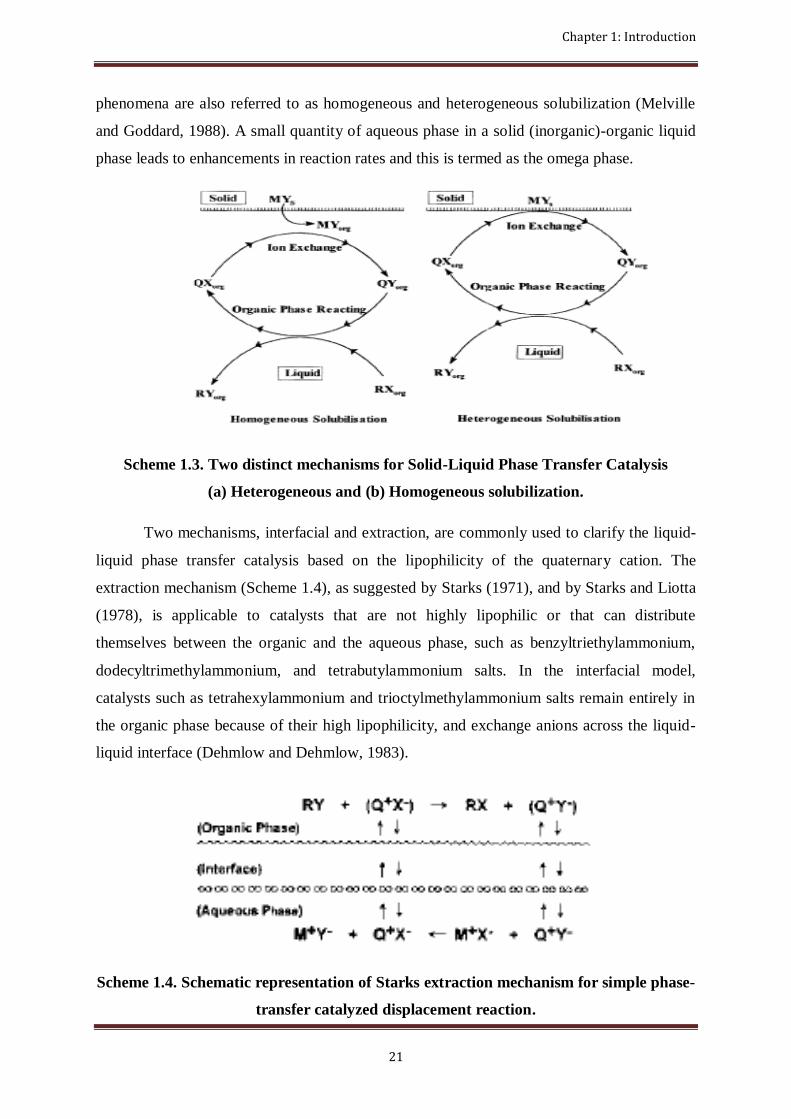
Chapter 1: Introduction
21
phenomena are also referred to as homogeneous and heterogeneous solubilization (Melville
and Goddard, 1988). A small quantity of aqueous phase in a solid (inorganic)-organic liquid
phase leads to enhancements in reaction rates and this is termed as the omega phase.
Scheme 1.3. Two distinct mechanisms for Solid-Liquid Phase Transfer Catalysis
(a) Heterogeneous and (b) Homogeneous solubilization.
Two mechanisms, interfacial and extraction, are commonly used to clarify the liquid-
liquid phase transfer catalysis based on the lipophilicity of the quaternary cation. The
extraction mechanism (Scheme 1.4), as suggested by Starks (1971), and by Starks and Liotta
(1978), is applicable to catalysts that are not highly lipophilic or that can distribute
themselves between the organic and the aqueous phase, such as benzyltriethylammonium,
dodecyltrimethylammonium, and tetrabutylammonium salts. In the interfacial model,
catalysts such as tetrahexylammonium and trioctylmethylammonium salts remain entirely in
the organic phase because of their high lipophilicity, and exchange anions across the liquid-
liquid interface (Dehmlow and Dehmlow, 1983).
Scheme 1.4. Schematic representation of Starks extraction mechanism for simple phase-
transfer catalyzed displacement reaction.
Chapter 1: Introduction
22
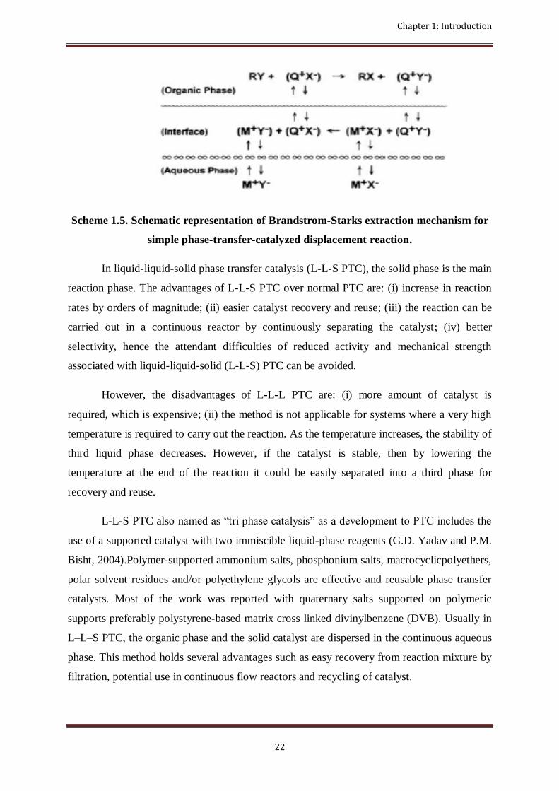
Scheme 1.5. Schematic representation of Brandstrom-Starks extraction mechanism for
simple phase-transfer-catalyzed displacement reaction.
In liquid-liquid-solid phase transfer catalysis (L-L-S PTC), the solid phase is the main
reaction phase. The advantages of L-L-S PTC over normal PTC are: (i) increase in reaction
rates by orders of magnitude; (ii) easier catalyst recovery and reuse; (iii) the reaction can be
carried out in a continuous reactor by continuously separating the catalyst; (iv) better
selectivity, hence the attendant difficulties of reduced activity and mechanical strength
associated with liquid-liquid-solid (L-L-S) PTC can be avoided.
However, the disadvantages of L-L-L PTC are: (i) more amount of catalyst is
required, which is expensive; (ii) the method is not applicable for systems where a very high
temperature is required to carry out the reaction. As the temperature increases, the stability of
third liquid phase decreases. However, if the catalyst is stable, then by lowering the
temperature at the end of the reaction it could be easily separated into a third phase for
recovery and reuse.
L-L-S PTC also named as “tri phase catalysis” as a development to PTC includes the
use of a supported catalyst with two immiscible liquid-phase reagents (G.D. Yadav and P.M.
Bisht, 2004).Polymer-supported ammonium salts, phosphonium salts, macrocyclicpolyethers,
polar solvent residues and/or polyethylene glycols are effective and reusable phase transfer
catalysts. Most of the work was reported with quaternary salts supported on polymeric
supports preferably polystyrene-based matrix cross linked divinylbenzene (DVB). Usually in
L–L–S PTC, the organic phase and the solid catalyst are dispersed in the continuous aqueous
phase. This method holds several advantages such as easy recovery from reaction mixture by
filtration, potential use in continuous flow reactors and recycling of catalyst.

Chapter 1: Introduction
23
The disadvantages of L–L–S PTC are higher initial cost of preparation and lower
catalytic activity due to diffusion limitations. The polymer-supported catalysts are generally
prepared by two methods, namely, chemical modifications of cross-linked polymer supports,
and copolymerization of functional monomers with cross-linkers. The microporous resins
have low specific surface areas and the polymeric chains shrink in a dry state or poor
solvents. Resins swell well in good solvents to extend the polymeric chains. The
macroporous resins have high specific surface areas and hardly swell in any solvent. In order
to overcome the diffusion limitations, spacer chains are provided on the support and this
technique leads to enhanced activity. Therefore, the overall rate in L–L–S PTC is determined
by one or more of the following rate controlling processes (i) mass transfer of reactants
(substrate and reagent), (ii) intra-particle diffusion of reactants, and (iii) the intrinsic rate at
the active site.
The wetting nature of support matters a great deal in L–L–S PTC (G.D. Yadav and
S.S. Naik, 2004). The microporous resins have low specific surface areas and the polymeric
chains shrink in a dry state or poor solvents. A macroporous polymer possessing high
porosity which swells considerably would be a better choice as support for the PTC.
1.6.2 Liquid-Liquid-Solid Phase Transfer Catalysis
Liquid-liquid phase transfer catalysis (LLPTC) is the most widely synthesized method
for solving the problem of the mutual insolubility of nonpolar and ionic compounds
(Dehmlow 1993, Starks et al. 1994, Weber and Gokel 1977, Halpern 1997 and Goldberg
1992). Two compounds in immiscible phases are able to react because of the PT catalyst.
However, processes using a two phase PT-catalytic reaction always encounter the separation
problem of purifying thefinal product from the catalyst. Regen (1975) first used a solid-phase
catalyst (triphasecatalyst (TC) or polymer-support catalyst), in which a tertiary amine was
immobilized on a polymer support, in the reaction of an organic reactant and an aqueous
reactant. From the industrial application point of view, the supported catalyst can be easily
separated from the final product and the unreacted reactants simply by filtration or
centrifugation. In addition, either the plug flow reactor (PFR) or the continuous stirred tank
reactor (CSTR) can be used to carry out the reaction. The most synthetic methods used for
triphase catalysis were studied by Regen and Beese (1975-79) and Tomoi and coworkers

Chapter 1: Introduction
24
(1981-83). Another advantage of triphase catalysis is that it can be easily adapted to
continuous processes was studied by Ragaini et al. (1986-90). Therefore, triphase catalysis
possesses high potential in industrial scale applications for synthesizing organic chemicals
from two immiscible reactants.
Quaternary onium salts, crown ethers, cryptands, and polyethylene glycol have all
been immobilized on various kinds of supports, including polymers (most commonly
methylstyrene-co-styrene resin cross-linked with divinylbenzene), alumina, silica gel, clays,
and zeolites. Because of diffusional limitations and high cost, the industrial applications of
immobilized catalysis (triphase catalysis) are not fully utilized. This unfortunate lack of
technology for industrial scale-up of triphase catalysis is mainly due to a lack of
understanding of the complex interactions between the three phases involved in such a
system. In addition to the support macrostructure, the support microenvironment is also
crucial in triphase catalysis since it determines the interactions of the aqueous and the organic
phases with the PT catalyst immobilized on the support surface studied by Naik and
Doraiswamy (1998). However, to date, few papers have discussed the microenvironment.
The effect of the internal molecularstructure of the polymer support, which plays an
important role in the imbibed composition, on the reaction rate has seldom been discussed. In
addition to the reactivity, for a TC in an organic and aqueous solution the volume swelling,
imbibed different solvent ratio, amount of active site, and mechanical structure of the catalyst
must be considered. Hence, these complex interactions in the microenvironment must be
solved in order to obtain a high reactivity of TC.
1.6.3 Mechanism of LLSPTC
In general, the reaction mechanism of the fluid–solid reactions involves: (1) mass
transfer of reactants from the bulk solution to the surface of the catalyst pellet, (2) diffusion
of reactant to the interior of the catalyst pellet (active site) through pores, and (3)
intrinsicreaction of reactant with active sites. Triphase catalysis is more complicated than
traditional heterogeneous catalysis, because it involves not merely diffusion of a single
gaseousor liquid phase into the solid catalyst. Both organic reactant and aqueous reactant
existwithin the pores of the polymer pellet. For step (3), a substitution reaction in the
organicphase and an ion-exchange reaction in the aqueous phase occurred. Diffusion of both

Chapter 1: Introduction
25
the aqueous and organic phases within the solid support is important and various
mechanismshave been proposed for triphase catalysis. However, each mechanism can only
explain asingle reaction system. Naik and Doraiswamy (1998) discussed these mechanisms in
their review paper.
Tundo and Venturello (1979-82) proposed a mechanism for a TC system using
silicagel as support to account for the active participation of the gel by adsorption of
reagents.Telford et al. (1986) suggested an alternation shell model that requires periodical
changes inthe liquid phase filling the pores of the catalyst. Schlunt and Chau (1986) from the
same research group tried to validate this model using a novel cyclic slurry reactor, and
indicatedthat only the catalyst in a thin shell near the particle surface was utilized. Tomoi and
Ford (1981) and Hradil et al. (1988) reported that a realistic mechanism involves the collision
ofdroplets of the organic phase with solid catalyst particles dispersed in a continuous
aqueousphase. Svec‟s model (1988) for transport of the organic reagent from the bulk phase
throughwater to the catalyst particle has been developed in terms of emulsion polymerization.
Because the triphase reaction involves not merely diffusion of a single phaseinto
thesolid support, the organic reaction take places in the organic phase and the ion-exchange
reaction occurs in the aqueous phase. The catalyst support is usually lipophilic. The organic
phase and aqueous phase fill the catalyst pores to form the continuous phaseand the disperse
phase, respectively. The interaction between quaternary salts as well asthe organic phase and
aqueous phase play a crucial role in promoting the triphase reaction rate.

CHAPTER 2
LITERATURE STUDY

Chapter 2: Literature study
28
Chapter 2
Literature Study
Abstract
This chapter deals with the literature study associated to the use of alkanolamines as H2S gas
absorbent, Different methods of synthesizing Benzyl mercaptan and Dibenzyl sulfide, Use of
various catalyst for the development of valuable products using the H2S present in gases.
2.1 Use of Aqueous Alkanolamines for the Removal of H2S
As discussed in preceding Chapter 1, hydrogen sulfide (H
2S) removal and retrieval from
the gas streams by ammonium hydroxide are well documented by Kohl and Nielsen, 1997. This
process was established by Hamblin, 1973 for removal of H2S from gas streams using
ammonium hydroxide to produce ammonium hydrosulfide, which was further oxidized by an air
stream to get an effluent stream containing ammonium polysulfide and treating the ammonium
polysulfide containing stream to recover elemental sulfur. In recent times, Asai et al. (1989)
studied the rates of simultaneous absorption of H2S and ammonia into water in an agitated vessel
with a flat interface and Rumpf et al. (1999) studied the simultaneous solubility of ammonia and
H2S in water at temperatures from 313 to 393 K and total pressures up to 0.7 MPa.
In contrast, aqueous alkanolamines are now-a-days extensively used in industry for the
removal of H2S from gas streams as deliberated in Chapter 1. Lot of research works is also
dedicated to the study on the equilibrium solubility of pure H2S, mixture of acid gases (H
2S and
CO2), and the mathematical representation of the experimental solubility data for H
2S, CO
2 and
their mixture using various alkanolamines (Lee et al., 1976; Lawson and Garst, 1976; Isaacs et
al., 1980; Austgen et al., 1989; Weiland et al., 1993; Kaewsichan et al., 2001; Al-Baghli et al.,
2001; Sidi-Boumedine et al., 2004; Vallée et al., 1999).

Chapter 2: Literature study
29
2.2 Preparation of Benzyl Mercaptan
Benzyl Mercaptan (BM) is useful as a raw material for the synthesis of herbicides in the
thiocarbamate family (Labat, 1989). It is predominantly used for the synthesis of herbicides like
esprocarb, prosulfocarb, tiocarbazil, etc. Preparation of BM from benzyl chloride using sodium
hydrosulfide and ammonium hydrosulfide reagents is well documented.
As for example, Hoffman and Reid (1923) prepared BM by reacting benzyl chloride with
ethanolic solution of molten sodium sulfide (melted at 90 0
C) saturated with H2S. The mixture
was allowed to stand in the cold, with frequent shaking for 4 days.
Heather (1988) prepared BM by reacting benzyl chloride with sodium hydrosulfide in the
two-phase conditions under H2S atmosphere at a temperature of about 50
0
C until approximately
90% of the starting material was converted to the BM (stirred for about 5 hours), then
temperature was elevated to about 80 0
C for the balance of the reaction (stirred for an additional
1.5 hours).
Bittell and Speier (1978) prepared BM by using a solution of NH
3 and methanol saturated
with H2S at 0
0
C. Benzyl chloride was added to this methanolic ammonium hydrosulfide
(NH4SH) solution at 0
0
C while H2S is slowly bubbled through the solution. The reaction was
completed in 1 hour with BM (92%) and DBS (8%) as the detectable products.
Labat (1989) prepared BM of more than 99% purity by reacting benzyl chloride and
ammonium hydrosulfide in a molar ratio NH4SH/C
6H
5CH
2Cl of at least 1, preferably between
about 1.05 and 1.5 under autogenous pressure in a closed reactor in two steps. The first step
comprised adding benzyl chloride to an aqueous hydrosulfide at a temperature below 800
C. The
second step involved heating the reaction mixture to a temperature in the range of 80-1000
C for
about 2 hours.
Chapter 2: Literature study
30
BM was also prepared from the corresponding thioacetates via Pd-catalyzed methanolysis
with borohydride exchange resin (Choi and Yoon, 1995a) and from the corresponding alkyl
halides and epoxides using hydrosulfide exchange resin in methanol in the presence of equimolar
amounts of triethylammonium chloride (Choi and Yoon, 1995b).
2.3 Preparation of Dibenzyl Sulfide
Dibenzyl sulfide (DBS) is havingmany applications such as additives for extreme
pressure lubricants, anti-wear additives for motor oils, stabilizers for photographic emulsions, in
refining and recovery of precious metals, and in different anticorrosive formulations (Pradhan
and Sharma, 1990). DBS can also be oxidized to prepare some useful synthetic intermediates like
dibenzylsulfoxide and dibenzylsulfone (Varma et al., 1997; Mohammadpoor-Baltork et al.,
2005).
Pradhan and Sharma (1990) synthesized DBS and bis (p-chlorobenzyl) sulfide by
reacting the respective chlorides with sodium sulfide using different phase transfer catalysts
(PTC) under liquid-liquid and solid-liquid mode. Tetrabutylammonium bromide (TBAB) was
found to be the most effective out of the six catalysts they tried under solid-liquid mode of
operation. A detailed study was performed using the best catalyst, TBAB.
Recently, Ido et al. (2000) investigated the property of third phase that affects the
reaction rate of benzyl chloride with sodium sulfide in the presence of tetrahexylammonium
bromide as a PTC.
Pradhan and Sharma (1992b) also studied the kinetics of preparation of DBS and bis (4-
chlorobenzyl) sulfide under solid-liquid modes with solid sodium sulfide using easily separable
unimpregnated inorganic solid catalyst like basic alumina and Amberlyst A27 (Cl−
form) anion
exchange resins.
Preparations of DBS using various types of reagent and starting material are also well
documented. For examples, Bandgar et al. (2000) prepared symmetrical sulfides including DBS
from the corresponding halides using polymer supported sulfide anion. Lakouraj et al. (2002)

Chapter 2: Literature study
31
and Movassagh and Mossadegh (2004a, 2004b) prepared DBS by the reduction of corresponding
disulfide using zinc powder in the presence of AlCl3
in aqueous media. DBS was also prepared
by the deoxygenation of corresponding sulfoxide using various reducing agents like Al-NiCl2-
6H2O (Raju et al., 2005), 1,3-dithiane in the presence of catalytic amounts of N-
bromosuccinimide, 2,4,4,6-tetrabromo-2, 5-cyclohexadienone or Br2
as the source of
electrophilic bromine (Iranpoor et al., 2002), and 2,6-Dihydroxypyridine in refluxing acetonitrile
(Miller et al., 2000). However, the reduction of sulfoxides with these compounds sometimes
suffer from serious disadvantages, such as use of an expensive reagent, difficult workup
procedures, harsh acidic conditions, very high reaction temperatures and long reaction times
(Iranpoor et al., 2002). In addition, the preparation of DBS by the reduction of corresponding
sulfoxide is impractical as sulfoxide itself is usually prepared by the oxidation of the sulfide.
The kinetics of reduction of nitrotoleunes by aqueous ammonium sulfide under LL PTC
with the use of (TBAB) as PTC was also studied (Narayan CPradhan, Anand V Patwardhan,
Sunil K Maity, 2006). The reaction of benzyl chloride with ammonium sulfide under LL PTC
using TBAB as PTC was also studied.
DBS was synthesized by reacting benzyl chloride and aqueous ammonium sulphide using
TBAB as phase transfer catalyst. The parametric study was done on the selectivity of DBS. It
was found that DBS can be selectively prepared by keeping high benzyl chloride concentration,
High NH3/H2S ratio (SujitSen, Patwardhan, S K Maity, N C Pradhan, 2007).
The reaction of BC with H2S rich MEA solution under L-L PTC was studied by SujitSen,
N.C.Pradhan and Patwardhan (2010). It was found that higher ratio of MEA/H2S favored the
formation Dibenzyl sulfide and if the ratio is lower it favors the formation of benzyl mercaptan.
TBAB catalyst was used.
2.4 Use of Tri Phase Catalyst
In the L-L PTC the catalyst was found to be soluble in both the phases and it possesses a
major problem that we do not get product in pure form. For removing the dissolved catalyst it
requires several water washes of the aqueous phase and treatment of the high volume of the

Chapter 2: Literature study
32
effluent. The separation of catalyst from the reaction mixture can be achieved by extraction,
distillation and adsorption and all these are energy intensive.
Pradhan and Sharma (1992), studied the catalytic effect of basic alumina and Amberlyst
A27(Cl-) form, on the reaction of benzyl chloride and parachlorobenzyl chloride with solid
sodium sulphide. The catalyst used in this case is Tri Phase catalyst.
G.D Yadav and N Kirthivasan(1997), studied the use of a novel catalyst based on
heteropolyacid supported on clay, particularlydodecatungstophosphoric acid (DTP) supported on
K-10 clay and they compared it with some other solid catalyst. DTP/K-10 catalyst was found to
be reusable and efficient at high temperatures.
G.D Yadav and S.S Naik (2000), prepared a clay supported phase transfer catalyst and
used it for the preparation of benzoic anhydride from benzoyl chloride and sodium benzoate
using clay-supported quaternary ammonium salts at 30 °C They found that clay supported
catalyst were more active than polymer supported catalyst. They found the selectivity to be
100%.
G.D Yadav and A.V Joshi (2001), used solid acid catalyst to synthesis tert amyl methyl
ether (TAME) by reacting tert amyl alcohol and methanol. A comparison was made among
different solid catalyst and Amberlyst-36 was found to be very effective.
G.D Yadav and O.V Badure (2007) studied the merits of creation of a third phase in
biphasic reaction. They found that use of L-L-L PTC enhances the conversion and increase the
selectivity also. He confirmed it by reacting phenol with benzyl chloride under L-L PTC and L-
L-L PTC separately and comparing the data obtained.
S K Maity, Narayan C Pradhan, A V Patwardhan (2008) studied reduction of p-
nitrotoluene by aqueous ammonium sulfide using serelite SRA400 a triphase catalysis reaction.
The rate of reduction of PNT was established to be proportional to the square of the
concentration of sulfide and to the cube of the concentration of PNT. Enhancement of the rate
was also observed with the once used catalyst due to the presence of elemental sulfur on the
surface of the catalyst.

Chapter 2: Literature study
33
B Gao, Z Wang, L Wang(2010), studied the effect of different type of quaternary salt
type tri phase catalyst on the esterification reaction of benzyl chloride with sodium acetate. They
found that 1) Among quaternary phosphonium and quaternary ammoninum type TPC,
ammonium type have the higher activity than quaternary ammonium-type catalyst, 2) TPC which
is highly lipophilic, substitution takes place at N atom and theyhave higher catalytic activity, 3)
TPC having longer spacer arm that links the quaternary onium salt group to the matrix
microsphere, shows higher catalytic activity, 4)The hydrophilic and hydrophobic property of the
TPC is affected by the bonding density of quaternary onium salt group and hence influences the
catalytic activity.
2.5 Conclusion
The simultaneous absorption of H2S and NH
3 into water (Asai et al., 1989; Rumpf et al.,
1999), and the use of ammonium hydroxide (Hamblin, 1973) and aqueous alkanolamine (Kohl
and Nielsen, 1997) for the removal of H2S from gas streams are well documented. However,
there is no information in the literature on the use of aqueous ammonium sulfide (or H2S-rich
aqueous alkanolamines that can be obtained from the corresponding unit) to produce any value-
added chemicals.
There is no published work on the detailed kinetic study of preparation of BM from
benzyl chloride using H2S-rich aqueous alkanolamine under tri-phase conditions in the presence
of a PTC. Moreover, no attempt has been made in the past to prepare DBS by the tri-phase
reaction of benzyl chloride with H2S-rich aqueous alkanolamine in the presence of anAmberlite
IR 400 as PTC.

CHAPTER 3
EXPERIMENTAL

Chapter 3: Experimental
35
Chapter 3
Experimental
Abstract
This chapter deals with the detailed experimental procedure followed in all cases of
experimental studies. It includes chemicals, equipment details, preparation of several reagents
and experimental procedure.
3.1 Chemicals and Catalyst
Hydrogen sulfide (H2S) prepared in the laboratory using Kipp’s apparatus and its
preparation and estimation of sulfide content in it are discussed in detail in below section. Sulfide
content is estimated by iodometric titration method. Water used here is purified by deionization.
Other reagents, including toluene (≥ 99.5 %) of analytical grade are acquired from Merck (India)
Ltd., Mumbai. Amberlite IR 400 was procured from Merck (India) Ltd., Mumbai.
Monoethanolamine (≥98 %) synthesis grade were procured from Merck (India) Ltd., Mumbai,
India. Iron (II) sulfide (FeS) sticks were obtained from Sigma Aldrich, Mumbai, India. Synthesis
grade benzyl chloride (≥ 99 %) was obtained from Merck (India) Limited, Mumbai, India. Also,
the chemicals used for iodometric titration for the estimation of sulfide content i.e., sodium
thiosulfate, potassium iodate, potassium iodide, starch powder, sulfuric acid (98 % pure) and
sodium hydroxide pellets of analytical grade were procured from Merck (India) Ltd., Mumbai.
3.2Preparation of H2S-Rich Aqueous Alkanolamines
Initially, for the preparation of H
2S-rich aqueous monoethanolamine (MEA) around 30-
35 wt% aqueous alkanolamine solution was prepared first by adding a suitable quantity of
desired alkanolamine in distilled water. Then H2S gas produced in the Kipp’s apparatus as shown
in below fig. 3.1., was bubbled through this aqueous alkanolamines in a 250 mL. standard gas
bubbler. H2S gas was prepared in laboratory scale in Kipp’s apparatus by reacting FeS sticks
with H2SO4. The concentration of H2SO4 was taken as 1 molar and the reaction carried out in
Kipp’s apparatus is as follows:

Chapter 3: Experimental
36
𝑭𝒆𝑺 + 𝑯𝟐𝑺𝑶𝟒
𝒆𝒙𝒐𝒕𝒉𝒆𝒓𝒎𝒊𝒄 𝒓𝒆𝒂𝒄𝒕𝒊𝒐𝒏 𝑯𝟐𝑺 𝒈 + 𝑭𝒆𝑺𝑶𝟒
Fig. 3.1.Schematic diagram for the absorption of H2S in MEA solution
Since the reaction of H2S with alkanolamines is exothermic (Kohl and Nielsen, 1997), the
gas bubbler containing aqueous alkanolamine was kept engrossed in an ice water bath in order to
prevent the oxidation of sulfide and consequently to prevent the formation of disulfide. The
unabsorbed H2S gas from the first bubbler was sent to another bubbler containing ∼ 1M MEA
solution whose outlet was open to the atmosphere. Liquid samples were withdrawn from time to
time after the gas bubbling was stopped and the samples were analyzed for sulfide content (Scott,
1966). The gas bubbling was continued until the desired sulfide concentration was obtained in
the aqueous alkanolamines.

Chapter 3: Experimental
37
3.3 Apparatus and Equipment Setup
In typical experiment, all the reactions were carried out into a thermostated (± 0.5 0C)
three-necked 250-ml (6.5 cm I.D.)in a batch mode equipped in a fully baffled mechanically
agitated glass reactor. Borosilicate glass beaker was used as the contactor and three-necked flask,
a dropping funnel serving the purposes of agitating the solution, inserting the thermometer,
taking samples, and feeding the feed. A 2.0 cm-diameter six-bladed glass disk turbine impeller
with the facility of speed regulation, located at a height of 1.5 cm from the bottom, was used for
stirring the reaction mixture. This arrangement ensured excellent solid-liquid mixing for high
mass transfer rate. The reactor assembly was kept in a constant temperature water bath whose
temperature could be controlled within ± 0.5 0C and mechanically stirred at a known speed with
an electric motor. The schematic diagram of the experimental setup is as shown in Fig. 3.2.
Fig. 3.2.Schematic diagram of the batch reactor assembly

Chapter 3: Experimental
38
3.4 Reaction Procedure
In a typical experimental run, known quantities of 50 mL of aqueous phase containing a
known concentration of sulfide was charged into the three neck batch reactor and kept well
agitated until the steady state temperature was reached. 50 mL of the organic phase containing
measured amount of organic reactant (benzyl chloride), and phase-transfer catalyst (Amberlite IR
400) arecharged into the reactor and then dissolved in organic solvent (toluene) to form an
organic solution. To start the reaction, the aqueous and organic solutions are mixed in a 250-mL
flask immersed in an isothermal water bath. The reaction mixture was then agitated at a constant
stirring speed. The organic phase sample about 0.1mL, of the organic layer was withdrawn at a
regular time interval of 60-480 min., after stopping the agitation and allowing the phases to
separate, was put into the test tubes. The sample (0.1 mL) was withdrawn periodically from the
reactor and put into the glass vials.
3.5 Method of Analysis
3.5.1 Determination of Sulfide Concentration
Initial sulfide concentrations were determined by standard iodometric titration method (Scott,
1966) as given below.
Preparation of standard (0.025 M) KIO3
solution: 4.28 gm of KIO3
was weighed accurately
and dissolved in distilled water and was made up to 1 L in a graduated volumetric flask.
Preparation of standard (0.1 M) sodium thiosulfate solution: 25 gm of Na
2S
2O
3.5H
2O
crystals was weighed and dissolved in distilled water and made up to 1 L in a graduated
volumetric flask with distilled water. About 0.1 g of sodium carbonate or three drops of
chloroform was added to this solution to keep the solution for more than a few days.
Standardization of sodium thiosulfate solution by standard potassium iodate solution: 25
mL of 0.025M KIO3
solution was taken and 1 gm (excess) of potassium iodide (KI) was added to
it followed by 3 mL of 1 M sulfuric acid. The liberated iodine (I2) was titrated with thiosulfate

Chapter 3: Experimental
39
solution. When the color of the solution became a pale yellow, it was diluted to ca. 200 mL with
distilled water. 2 mL of starch solution was added, and the titration was continued until the color
changed from blue to colorless. The chemical reaction involved in this titration is given below.
𝑲𝑰𝑶𝟑 + 𝟓𝑲𝑰 + 𝟑𝑯𝟐𝑺𝑶𝟒 ⇌ 𝟑𝑰𝟐 + 𝟑𝑯𝟐𝑶 + 𝟑𝑲𝟐𝑺𝑶𝟒
𝟐𝑵𝒂𝟐𝑺𝟐𝑶𝟑 + 𝑰𝟐 ⇌ 𝑵𝒂𝟐𝑺𝟒𝑶𝟔 + 𝟐𝑵𝒂𝑰
Therefore, 1 mole of KIO
3 ≡ 3×2 mole of Na
2S
2O
3.
∴ 𝑆𝑡𝑟𝑒𝑛𝑔𝑡 𝑜𝑓 𝑡𝑖𝑜𝑠𝑢𝑙𝑓𝑎𝑡𝑒 𝑠𝑜𝑙𝑢𝑡𝑜𝑛 = 6 ∗ 𝑠𝑡𝑟𝑒𝑛𝑔𝑡 𝑜𝑓 𝐾𝐼𝑂3 ∗ 𝑣𝑜𝑙𝑢𝑚𝑒 𝑜𝑓 𝐾𝐼𝑂3
𝑣𝑜𝑙𝑢𝑚𝑒 𝑜𝑓 𝑡𝑖𝑜𝑠𝑢𝑙𝑓𝑎𝑡𝑒 𝑐𝑜𝑛𝑠𝑚𝑒𝑑
Estimation of sulfide concentration: Hydrogen sulfide and soluble sulfides can be determined
by oxidation with potassium iodate in an alkaline medium. 15 mL of standard (0.025M)
potassium iodate solution was taken in a conical flask. 10 mL of sulfide solution containing
about 2.5 mg of sulfide was then added to it followed by the addition 10 mL of 10M sodium
hydroxide solution. The mixture was boiled gently for about 10 minutes, cooled, and 5 mL of KI
solution and 20 mL of 4M sulfuric acid solution were added to it. The liberated iodine was
titrated, which was equivalent to the unused potassium iodate, with a standard 0.1M sodium
thiosulfate in the usual manner. The potassium iodate in the alkaline medium oxidizes the sulfide
to sulfate as given by the following reaction. For sulfide solution having sufficiently high sulfide
concentration, suitable dilution was made before the estimation of sulfide by above mentioned
procedure.
𝟒𝑰𝑶𝟑− + 𝟔𝑶𝑯− + 𝟑𝑺𝟐− = 𝟑𝑺𝑶𝟒
𝟐− + 𝟒𝑰− + 𝟔𝑯𝟐𝑶
4 mole of IO3-≡ 3 mole of S
2-
𝑯𝟐𝑺 𝒄𝒐𝒏𝒄𝒆𝒏𝒕𝒓𝒂𝒕𝒊𝒐𝒏 = 𝟏𝟓 ∗ 𝑺𝒊𝒐𝒅𝒂𝒕𝒆 − 𝑽𝒕𝒉𝒊𝒐𝒔𝒖𝒍𝒇𝒂𝒕𝒆 ∗ 𝑺𝒕𝒉𝒊𝒐𝒔𝒖𝒍𝒇𝒂𝒕𝒆
𝟔 ∗
𝟑
𝟒∗𝑵𝒅
𝟏𝟎
Where Siodate= Strength of KIO
3
Vthiosulfate = Volume of thiosulfate
Sthiosulfate= Strength of thiosulfate
Nd= Number of times of dilution

Chapter 3: Experimental
40
3.5.2 Analysis of Organic Phase
All samples and the contents of Dibenzyl sulfide, Benzyl mercaptan and dissolvent from
the organic phase were analyzed by gas liquid chromatography (GLC). A Chemito Model 8610
GC interfaced with Shimadzu C-R6A Chromatopac Data Processor was used for the
analysis.The analyzing conditions are as follows: a gas chromatography (GC-8610) with a
detector, Flame Ionization Detector (FID). The column used is a 2 m × 3 mm stainless steel
column packed with Chromosorb WHP (80-100 mesh), which were impregnated with 10% SE-
30 was used for analysis in conjunction with a FID. Synthetic mixtures of the reactant and
internal standard were used to calibrate the chromatograms and quantify the data. The optimum
operation conditions of GC are the following: injection temperature, 150 0C; column
temperature, 145 0C; FID temperature, 145
0C; carrier gas, nitrogen gas with a flow rate of 30
mL.min-1
; and sample volume, 0.5 µL during the analysis. The products formed were analyzed
by comparison of their retention times with authentic samples. Yields were determined from
standard curve and using acetone as internal standard. In L-L-SPTC, the sole products, Dibenzyl
sulfide and Benzyl mercaptan, were confirmed by GC analysis.
CHAPTER 4
REACTION OF BENZYL CHLORIDE WITH
H2S-RICH AQUEOUS
MONOETHANOLAMINE UNDER
LIQUID−LIQUID-SOLID PHASE TRANSFER
CATALYSIS

Chapter 4: Reaction of Benzyl Chloride with H2S-Rich Aqueous Monoethanolamine under Liquid-Liquid-Solid Phase Transfer Catalysis
42
Chapter 4
Reaction of Benzyl Chloride with H2S-Rich Aqueous Monoethanolamine
under Liquid-Liquid-Solid Phase Transfer Catalysis
Abstract
This chapter describes a detailed study for the synthesis of Dibenzyl sulfide selectively from
reaction of benzyl chloride (BC) with H2S-rich aqueous monoethanolamine under liquid-liquid-
solid phase transfer catalysis (LLS-PTC).It includes parametric studies following mechanistic
investigation of the process parameters to maximize BC conversion and DBS selectivity. In
parametric studies, effects of temperature, catalyst concentration, BC concentration, initial
sulfide concentration and MEA concentration on BC conversion and DBS selectivity were
examined.
4.1 Introduction
In the present work, the reaction of benzyl chloride (BC) with H2S-rich aqueous
monoethanolamine (MEA) can give both Dibenzyl sulfide (DBS) and Benzyl mercaptan (BM) as
products as per the below scheme. The commercial importance of these compounds has been
mentioned in Chapter 2. In the present study, the reaction was carried out in batch mode under
tri-phase conditions (liquid-liquid-solid) both in the absence and in the presence of phase transfer
catalyst (PTC), namely, Amberlite IR 400. Dibenzyl sulfide (DBS) and benzyl mercaptan (BM)
were detected as the products from the reaction mixture by gas liquid chromatography (GLC).
Although there is a possibility of formation of benzyl alcohol by alkaline hydrolysis of benzyl
chloride, it was not detected in the reaction mixture even after a batch time of 10 hrs.
Accordingly, the reaction system may be represented by Scheme 4.1.
The term ‘selectivity’ of the two products, DBS and BM, used in this study is defined as
the fraction of benzyl chloride converted to a particular product divided by the total fractional
conversion of benzyl chloride. The selectivity of DBS (or BM) was maximized by changing
various parameters such as stirring speed, temperature, aqueous sulfide concentration, MEA

Chapter 4: Reaction of Benzyl Chloride with H2S-Rich Aqueous Monoethanolamine under Liquid-Liquid-Solid Phase Transfer Catalysis
43
concentration, catalyst loading and concentration of benzyl chlorideas discussed below in the
respective sections. From the detailed study of effects of various parameters on the reaction, a
suitable mechanism was established which could explain the course of the reaction.
Scheme 4.1
Parametric studies have been performed following one-variable-at-a-time (OVAT)
approach to see the effect of various parameters such as speed of agitation, temperature, aqueous
sulfide concentration, MEA concentration, catalyst loading and BC concentration on BC
conversion and DBS selectivity.
4.2 Results and Discussion
4.2.1 Parametric Study
4.2.1.1 Effect of Speed of Agitation
The mass transfer as well as the chemical reaction is important in influencing the
conversion on rate of the three-phase reaction. In this study, to ascertain the influence of mass
transfer resistance of the reactants to the reaction phase, effect of the agitation speed on the
conversion of benzyl chloride was varied in the range 1000-2500 rpm under otherwise identical
experimental conditions in the presence of PTC (Amberlite IR 400), as shown in Fig. 4.1. For
agitation speed over 1000 rpm, the conversion of benzyl chloride is insensitive to the agitation
speed. This result is different from that of other reaction systems that require a high agitation
speed to reach a constant value of conversion.

Chapter 4: Reaction of Benzyl Chloride with H2S-Rich Aqueous Monoethanolamine under Liquid-Liquid-Solid Phase Transfer Catalysis
44
The main reason is that other reactions systems need a relatively larger interfacial area to
increase the mass transfer rate. However, the active intermediate of the catalyst (Q2S), which is
hydrophobic, likes to stay in the organic phase, in which the interfacial area is not so important.
As it is evident from the figure, the variation of conversion of benzyl chloride with stirring speed
is so small that the mass transfer factors become unimportant and the reaction rate is controlled
purely by the kinetics. Therefore, all other experiments were performed at a stirring speed of
1500 rpm in order to ensure the absence of mass transfer resistance.
0 60 120 180 240 300 360 420 480
0
10
20
30
40
50
60
70
80
90
100
Stirring Speed
1000 RPM
1500 RPM
2000 RPM
% C
on
ve
rs
ion
of
Be
nzy
l C
hlo
rid
e
Reaction Time (min)
Fig. 4.1: Effect of speed of agitation on the conversion of BC.
Operating Condition: Volume of organic phase =50 ml; concentration of BC = 2.6 M org. phase;
concentration of toluene = 6.6 M org. phase; volume of aqueous phase = 50 ml, concentration of
catalyst = 0.1 M org. phase; concentration of sulfide = 2 M, MEA/H2S mole ratio = 1.74;
temperature = 45 0C.

Chapter 4: Reaction of Benzyl Chloride with H2S-Rich Aqueous Monoethanolamine under Liquid-Liquid-Solid Phase Transfer Catalysis
45
500 1000 1500 2000 2500 3000
20
30
40
50
60
70
In absence of catalyst
In presence of catalyst%
C
on
versi
on
of
Ben
zy
l ch
lorid
e
Stirring Speed (RPM)
Effect of stirring speed on conversion in presence and absence of catalyst
Fig. 4.2: Effect of speed of agitation onconversion of BC in presence & absence of catalyst.
4.2.1.2 Effect of Temperature
The present work investigates the reaction of BC with Toluene catalyzed by a new resin
catalyst Amberlite IR 400 in the presence of H2S-rich aqueous monoethanolamine under various
reaction temperatures was studied under otherwise similar reaction conditions at six different
temperatures in the range 30 – 55 0C. Fig. 4.3 shows the effect of temperature on conversion of
benzyl chloride. As expected, the rates of most organic reactions increase with the increase in
temperature from the transition-state theory. For this reason, it is considered that increasing
temperature is likely to promote slow organic phase reactions in PTC system. It is obvious that
the reactivity (conversion) of BC is increased with an increase in the temperature. The reason is
that the number of reactant molecules, which possess larger activated energy at a higher
temperature. Thus the conversion of BC is increased. The other point is that the collision of the
. .% 100%
.
% 100%
initialconc finalconcConversionofBC
initialconc
molesofDBSformedSelectivityofDBS
molesofBCconverted

Chapter 4: Reaction of Benzyl Chloride with H2S-Rich Aqueous Monoethanolamine under Liquid-Liquid-Solid Phase Transfer Catalysis
46
reactants at higher temperature is also increased. Hence, the reaction rate increases with
increasing temperature.
0 60 120 180 240 300 360 420 480
0
10
20
30
40
50
60
70
80
90
100
Temperature
30 0C
35 0C
40 0C
45 0C
50 0C
55 0C
C
on
ve
rsio
n o
f B
en
zy
l c
hlo
rid
e (
%)
Time (min)
Fig. 4.3: Effect of temperature on BC conversion
Operating Condition: Volume of organic phase – 50ml, Volume of Aqueous Phase – 50ml,
Concentration of benzyl chloride – 2.8M, Concentration of toluene = 6.6M org. phase; volume of aqueous
phase = 50ml; Concentration of catalyst = 0.1M org. phase; Concentration of sulfide = 2.3M, MEA/H2S
ratio – 2.1; Stirring speed – 1500 rpm.
The effect of temperature on the selectivity of DBS is shown in Fig. 4.4. As observed
from the table, the selectivity of DBS is almost unaffected by the temperature for a given
conversion of benzyl chloride. Therefore, with an increase in temperature, the reaction rate
increases without significantly affecting the selectivity of the products.

Chapter 4: Reaction of Benzyl Chloride with H2S-Rich Aqueous Monoethanolamine under Liquid-Liquid-Solid Phase Transfer Catalysis
47
0 60 120 180 240 300 360 420 480
0
10
20
30
40
50
60
70
80
90
100
% S
ele
cti
vit
y o
f D
ibe
nzy
l s
ulf
ide
(%
)
Time (min)
Temperature
30 0C
35 0C
40 0C
45 0C
50 0C
55 0C
Fig. 4.4: Effect of temperature on DBS selectivity
Operating Condition: Volume of organic phase – 50ml, Volume of Aqueous Phase – 50ml,
Concentration of benzyl chloride – 2.8M, Concentration of toluene = 6.6M org. phase; volume of aqueous
phase = 50ml; Concentration of catalyst = 0.1M org. phase; Concentration of sulfide = 2.3M, MEA/H2S
ratio – 2.1; Stirring speed – 1500 rpm.
Initial rate of reaction of benzyl chloride was calculated at different temperatures and an
Arrhenius plot of –ln (initial rate) versus 1/T was made as shown in Fig. 4.5 and Fig. 4.6. The
apparent activation energy for the reaction of benzyl chloride was calculated from the slope of
the straight line as 40.7 KJ mol-1
. The observed high apparent activation energy again confirms
the fact that the reaction is kinetically controlled.

Chapter 4: Reaction of Benzyl Chloride with H2S-Rich Aqueous Monoethanolamine under Liquid-Liquid-Solid Phase Transfer Catalysis
48
0 60 120 180 240 300 360 420 480
0.0
0.1
0.2
0.3
0.4
0.5
0.6
-ln
(1-X
A)
TIME (min)
y=0.0004x
R2=0.98134
y=0.0007x
R2=0.96752
y=0.0011x
R2=0.97346
y=0.0023x
R2=0.97737
y=0.0036x
R2=0.95274
y=0.00386x
R2=0.98352
350C; 40
0C; 45
0C; 50
0C; 55
0C
Kinetic plot for the effect of temperature
Fig. 4.5: Kinetic plot for the effect of temperature
0.00305 0.00310 0.00315 0.00320 0.00325 0.00330
-12
-10
-8
-6
-4
-2
0
ln(i
niti
al r
ate
(K
.mo
l/m3.s
)
1/T (K-1)
Adj. R2
=0.98198
Linear Fit
Arrhenius Plot in presence of PTC (Amberlite IR 400)
Fig. 4.6: Arrhenius plot for activation energy
Operating Condition :Volume of organic phase – 50ml, Volume of Aqueous Phase – 50ml, Concentration of benzyl
chloride – 2.8M, Concentration of toluene = 6.6M org. phase; volume of aqueous phase = 50ml; Concentration of
catalyst = 0.1M org. phase; Concentration of sulfide = 2.3M, MEA/H2S ratio – 2.1; Stirring speed – 1500 rpm.

Chapter 4: Reaction of Benzyl Chloride with H2S-Rich Aqueous Monoethanolamine under Liquid-Liquid-Solid Phase Transfer Catalysis
49
4.2.1.3 Effect of Catalyst (Amberlite IR 400) Quantity
The effect of catalyst (Amberlite IR 400) quantity on the conversion of benzyl chloride
was studied in the concentration range of 0% (w/v) to 15% (w/v) of organic phase, as shown in
Fig. 4.7. With the increase in catalyst quantity, the conversion of benzyl chloride as well as
reaction rate increases.Only by increasing the catalyst concentration, benzyl chloride conversion
of more than 90% was achieved whereas it was about 76% without catalyst even after 480 min of
reaction under otherwise identical conditions. Fig. 4.7 also shows that over certain concentration
of the catalyst, ca. 0.10 M of organic phase, the conversion of BC becomes constant. This could
be attributed to interface saturation, which means that mass transfer of the active species into
organic phase reaches a maximum value. The selectivity of DBS increases with increase in
catalyst concentration as shown in Figure 4.8. Therefore, the selectivity of BM decreases with
catalyst loading.
For liquid-liquid-solid tri-phase reactions, the overall rate of reaction is governed by rate
of transportation of anions from aqueous phase to organic phase. In presence of PTC, the
transportation of anions (in present case S2-
and HS-) is facilitated and the reaction becomes
organic-phase limited. The hydrosulfide (HS-) and sulfide (S
2-) ions present in the aqueous phase
readily form ion pairs [Q+HS
- and Q
+S
2-Q
+], with quaternary cations, [Q
+], and are transferred to
the organic phase and then reacts with benzyl chloride. With increased catalyst concentration,
more amount of [Q+]2S
2− ion pair is formed and transferred to the organic phase and reacts with
benzyl chloride to form DBS. The selectivity of DBS, therefore, increases with increase in
catalyst concentration.

Chapter 4: Reaction of Benzyl Chloride with H2S-Rich Aqueous Monoethanolamine under Liquid-Liquid-Solid Phase Transfer Catalysis
50
0 60 120 180 240 300 360 420 480
0
10
20
30
40
50
60
70
80
90
100
% C
on
ve
rsio
n o
f B
en
zy
l C
hlo
rid
e
Reaction Time (min)
Catalyst loading
0 % (W/V), organic phase
5 % (W/V), organic phase
10 % (W/V), organic phase
15 % (W/V), organic phase
Effect of catalyst loading on the conversion of Benzyl chloride
Fig. 4.7: Effect of the catalyst quantity on BC conversion
Operating Condition :Volume of organic phase – 50ml; Volume of Aqueous Phase – 50ml; Concentration of benzyl
chloride – 2.8M; Sulfide concentration – 2.3M; MEA/H2S mole ratio – 2.1; Temperature – 45 0C; Stirring speed –
1500 rpm.
0 60 120 180 240 300 360 420 480
0
5
10
15
20
25
30
35
40
45
Catalyst loading
0% (W/V), Organic Phase
5% (W/V), Organic Phase
10% (W/V),Organic Phase
15% (W/V),Organic Phase
% S
ele
cti
vit
y o
f D
ibe
nzy
l S
ulf
ide
Reaction Time (min)
Effect of catalyst loading on the Dibenzyl sulfide selectivity
Fig. 4.8: Effect of the catalyst quantity on DBS selectivity
Operating Condition :Volume of organic phase – 50ml; Volume of Aqueous Phase – 50ml; Concentration of benzyl
chloride – 2.8M; Sulfide concentration – 2.3M; MEA/H2S mole ratio – 2.1; Temperature – 45 0C; Stirring speed –
1500 rpm.

Chapter 4: Reaction of Benzyl Chloride with H2S-Rich Aqueous Monoethanolamine under Liquid-Liquid-Solid Phase Transfer Catalysis
51
4.2.1.4 Effect of Initial MEA: Sulfide Mole Ratio
The effect of initial MEA: Sulfide mole ratio on the conversion of benzyl chloride and
the selectivity of various products were studied in two different ways: (1) by varying the initial
concentration of sulfide keeping the initial concentration of MEA in the aqueous phase constant,
and (2) by varying the initial concentration of MEA keeping the initial concentration of sulfide in
the aqueous phase constant.
4.2.1.4.1 Effect of Initial Sulfideconcentration
The effect of MEA: sulfide mole ratio was studied by varying the initial sulfide
concentration in the aqueous phase keeping MEA concentration fixed at 3.5M. For fixed MEA
concentration, with an increase in MEA: sulfide ratio (or with a decrease in initial sulfide
concentration in the aqueous phase), the conversion of BC decreases because of the limited
quantity of sulfide in the aqueous phase as shown in Fig. 4.9. Keeping all other reaction
conditions fixed, a conversion of more than 90% was achieved after 480 min of run.
0 60 120 180 240 300 360 420 480
0
10
20
30
40
50
60
70
80
90
Sulfide concentration
0.6 M
0.8 M
1.1 M
1.6 M
2 M
% C
on
ver
sio
n o
f B
enzy
l ch
lori
de
Reaction Time (min)
Effect of initial sulfide concentration on the conversion of Benzyl chloride
Fig. 4.9: Effect of initial sulfide concentration on BC conversion
Operating Condition: Volume of organic phase – 50ml; Volume of Aqueous Phase – 50ml; Concentration of benzyl
chloride – 2.8M org. phase; Concentration of MEA = 3.5 M;Concentration of catalyst = 0.1M org. phase;
Temperature – 45 0C; Stirring speed – 1500 rpm.

Chapter 4: Reaction of Benzyl Chloride with H2S-Rich Aqueous Monoethanolamine under Liquid-Liquid-Solid Phase Transfer Catalysis
52
However, an opposite trend was observed for the selectivity of DBS. For a fixed
conversion of benzyl chloride, the selectivity of DBS increases with an increase in MEA: sulfide
mole ratio (or decrease in initial sulfide concentration) as shown in Fig. 4.10.Keeping all other
reaction conditions fixed, a conversion of more than 78% was achieved after 480 min of run.
However, an opposite trend was observed (Fig.4.10) for selectivity of DBS.Further increase of
sulfide concentration results in decrease of selectivity of DBS as observed from the figure.
0 60 120 180 240 300 360 420 480
0
20
40
60
80
100
Sulfide concentration
2.0 M
1.6 M
1.1 M
0.8 M
0.6 M
% S
ele
cti
vit
y o
f D
iben
zy
l S
ulf
ide
Reaction Time (min)
Effect of initial sulfide concentration on Dibenzyl sulfide selectivity
Fig. 4.10: Effect of initial sulfide concentration on DBS selectivity
Operating Condition:Volume of organic phase – 50ml; Volume of Aqueous Phase – 50ml; Concentration of benzyl
chloride – 2.8M org. phase; Concentration of MEA = 3.5 M;Concentration of catalyst = 0.1M org. phase;
Temperature – 45 0C; Stirring speed – 1500 rpm.
With increase in sulfide concentration, selectivity of DBS decreases. This can be
explained by considering the fact that although MEA as such does not participate in the reaction
with BC, it does affect the equilibrium among MEA, H2S, and water, which results in two active
anions, sulfide (S2-
) and hydrosulfide (HS-), in the aqueous phase. These two active anions
participate in two different reactions. In the presence of a base (MEA), the dissociation
equilibrium shifts toward more ionization and the concentration of sulfide ions, relative to
hydrosulfide ions in the aqueous phase, increases as the MEA concentration increases.
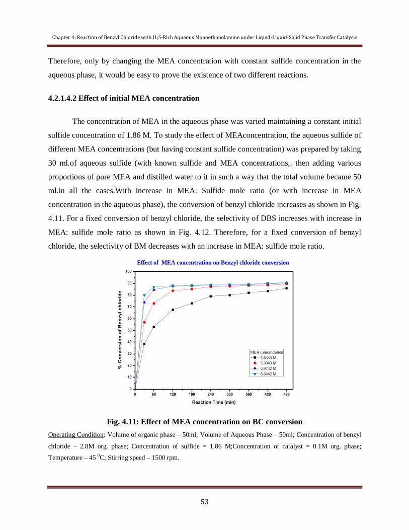
Chapter 4: Reaction of Benzyl Chloride with H2S-Rich Aqueous Monoethanolamine under Liquid-Liquid-Solid Phase Transfer Catalysis
53
Therefore, only by changing the MEA concentration with constant sulfide concentration in the
aqueous phase, it would be easy to prove the existence of two different reactions.
4.2.1.4.2 Effect of initial MEA concentration
The concentration of MEA in the aqueous phase was varied maintaining a constant initial
sulfide concentration of 1.86 M. To study the effect of MEAconcentration, the aqueous sulfide of
different MEA concentrations (but having constant sulfide concentration) was prepared by taking
30 ml.of aqueous sulfide (with known sulfide and MEA concentrations,. then adding various
proportions of pure MEA and distilled water to it in such a way that the total volume became 50
ml.in all the cases.With increase in MEA: Sulfide mole ratio (or with increase in MEA
concentration in the aqueous phase), the conversion of benzyl chloride increases as shown in Fig.
4.11. For a fixed conversion of benzyl chloride, the selectivity of DBS increases with increase in
MEA: sulfide mole ratio as shown in Fig. 4.12. Therefore, for a fixed conversion of benzyl
chloride, the selectivity of BM decreases with an increase in MEA: sulfide mole ratio.
0 60 120 180 240 300 360 420 480
0
10
20
30
40
50
60
70
80
90
100
% C
on
ve
rsio
n o
f B
en
zy
l c
hlo
rid
e
Reaction Time (min)
MEA Concentration
3.6343 M
5.3043 M
6.9742 M
8.6442 M
Effect of MEA concentration on Benzyl chloride conversion
Fig. 4.11: Effect of MEA concentration on BC conversion
Operating Condition: Volume of organic phase – 50ml; Volume of Aqueous Phase – 50ml; Concentration of benzyl
chloride – 2.8M org. phase; Concentration of sulfide = 1.86 M;Concentration of catalyst = 0.1M org. phase;
Temperature – 45 0C; Stirring speed – 1500 rpm.
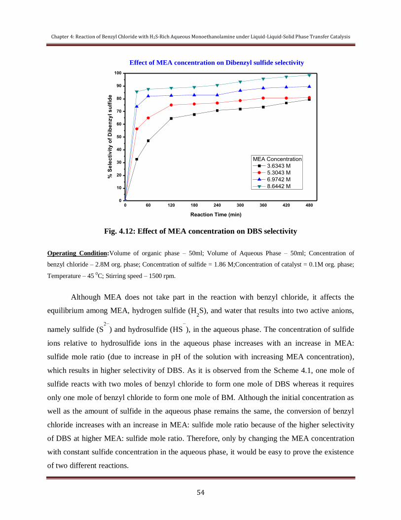
Chapter 4: Reaction of Benzyl Chloride with H2S-Rich Aqueous Monoethanolamine under Liquid-Liquid-Solid Phase Transfer Catalysis
54
0 60 120 180 240 300 360 420 4800
10
20
30
40
50
60
70
80
90
100
% S
ele
cti
vit
y o
f D
ibe
nzy
l s
ulf
ide
Reaction Time (min)
MEA Concentration
3.6343 M
5.3043 M
6.9742 M
8.6442 M
Effect of MEA concentration on Dibenzyl sulfide selectivity
Fig. 4.12: Effect of MEA concentration on DBS selectivity
Operating Condition:Volume of organic phase – 50ml; Volume of Aqueous Phase – 50ml; Concentration of
benzyl chloride – 2.8M org. phase; Concentration of sulfide = 1.86 M;Concentration of catalyst = 0.1M org. phase;
Temperature – 45 0C; Stirring speed – 1500 rpm.
Although MEA does not take part in the reaction with benzyl chloride, it affects the
equilibrium among MEA, hydrogen sulfide (H2S), and water that results into two active anions,
namely sulfide (S2−
) and hydrosulfide (HS−
), in the aqueous phase. The concentration of sulfide
ions relative to hydrosulfide ions in the aqueous phase increases with an increase in MEA:
sulfide mole ratio (due to increase in pH of the solution with increasing MEA concentration),
which results in higher selectivity of DBS. As it is observed from the Scheme 4.1, one mole of
sulfide reacts with two moles of benzyl chloride to form one mole of DBS whereas it requires
only one mole of benzyl chloride to form one mole of BM. Although the initial concentration as
well as the amount of sulfide in the aqueous phase remains the same, the conversion of benzyl
chloride increases with an increase in MEA: sulfide mole ratio because of the higher selectivity
of DBS at higher MEA: sulfide mole ratio. Therefore, only by changing the MEA concentration
with constant sulfide concentration in the aqueous phase, it would be easy to prove the existence
of two different reactions.

Chapter 4: Reaction of Benzyl Chloride with H2S-Rich Aqueous Monoethanolamine under Liquid-Liquid-Solid Phase Transfer Catalysis
55
4.2.1.5 Effect of Concentration of Benzyl Chloride
The effect of benzyl chloride concentration on the conversion of benzyl chloride was
studied at three different concentrations in the range of 1.75 – 4.25M as shown in the Fig. 4.13. It
is seen from this figure that with an increase in the concentration of benzyl chloride, the
conversion of benzyl chloride decreases because of limited quantity of sulfide present in the
aqueous phase. With benzyl chloride concentration of 1.75M, almost 90% conversion of benzyl
chloride was observed whereas the conversion of benzyl chloride was only about 62% with
benzyl chloride concentration of 4.25M even after 480 min of reaction under otherwise identical
experimental conditions as observed from the figure.
0 60 120 180 240 300 360 420 480
0
10
20
30
40
50
60
70
80
90
100
Concentration of Benzyl chloride
1.75M org. phase
3.00M org. phase
4.25M org. phase
% C
on
ve
rsio
n o
f B
en
zy
l C
hlo
rid
e
Reaction Time (min)
Effect of concentration of BC on conversion of BC
Fig. 4.13: Effect of concentration of BC on conversion of BC
Operating Condition:Volume of organic phase – 50ml; Volume of Aqueous Phase – 50ml; Concentration of
benzyl chloride – 2.8M org. phase; Concentration of sulfide = 1.86 M;Concentration of catalyst = 0.1M org. phase;
Temperature – 45 0C; Stirring speed – 1500 rpm.
The selectivity of DBS increases sharply with an increase in the concentration of benzyl
chloride as shown in Fig. 4.14. As observed from the figure, the selectivity of DBS is about 55%
for 4.25M of benzyl chloride concentration, whereas the selectivity of DBS is only about 16%

Chapter 4: Reaction of Benzyl Chloride with H2S-Rich Aqueous Monoethanolamine under Liquid-Liquid-Solid Phase Transfer Catalysis
56
for 1.75M of benzyl chloride concentration even after 480 minutes of reaction under otherwise
identical experimental conditions.
0 60 120 180 240 300 360 420 480 540
0
10
20
30
40
50
Concentration of Benzyl chloride
1.75M
3.00M
4.25M
% S
ele
cti
vit
y o
f D
ibe
nzy
l S
ulf
ide
Reaction Time (min)
Effect of concentration of BC on selectivity of DBS
Fig. 4.14: Effect of concentration of BC on selectivity of DBS
Operating Condition:Volume of organic phase – 50ml; Volume of Aqueous Phase – 50ml; Concentration of
benzyl chloride – 2.8M org. phase; Concentration of sulfide = 1.86 M;Concentration of catalyst = 0.1M org. phase;
Temperature – 45 0C; Stirring speed – 1500 rpm.
From the plot of selectivity of DBS vs conversion of BC (Fig. 4.15), it is seen that there
is a sharp increase of slope of the curve with increase in the concentration of BC. It is also
observed from the figure that the selectivity of BM is higher than that of DBS during the initial
stage of the reaction. Therefore, it can be concluded that the reaction leading to the formation of
BM is very fast as compared to that leading to the formation of DBS. Therefore, at lower benzyl
chloride concentrations, there will be insufficient quantity of benzyl chloride present to produce
DBS, which results in low selectivity of DBS.

Chapter 4: Reaction of Benzyl Chloride with H2S-Rich Aqueous Monoethanolamine under Liquid-Liquid-Solid Phase Transfer Catalysis
57
0 20 40 60 80 100
0
10
20
30
40
50
60
70
80
90
100
Concentration of Benzyl chloride
1.75M org. phase
3.00M org. phase
4.25M org. phase
% S
ele
cti
vit
y o
f D
ibe
nzy
l s
ulf
ide
% Conversion of Benzyl chloride
Relatonship between conversion of BC and selectivity of DBS under BC concentartion
Fig. 4.15: Relationship between conversion of BC and selectivity of DBS under different BC
concentrations
Operating Condition: Volume of organic phase – 50ml; Volume of Aqueous Phase – 50ml; Concentration of
sulfide = 1.86 M;Concentration of MEA = 3.5 M; Concentration of catalyst = 0.1M org. phase; Temperature – 450C;
Stirring speed – 1500 rpm.
With lower benzyl chloride concentrations in the organic phase, almost complete
conversion of benzyl chloride was achieved. This resulted in very low selectivity of DBS, that is,
high selectivity of BM and incomplete sulfide utilization in the aqueous phase. On the other
hand, with an excess of benzyl chloride, higher DBS selectivity was achieved with efficient
utilization of sulfide in the aqueous phase although the benzyl chloride conversion remained low.
Therefore, a question of optimization among the opposing factors (conversion of benzyl chloride,
utilization of sulfide, and selectivity of DBS) arises, and needs to be addressed.

Chapter 4: Reaction of Benzyl Chloride with H2S-Rich Aqueous Monoethanolamine under Liquid-Liquid-Solid Phase Transfer Catalysis
58
4.2.2Mechanistic Investigation
The reaction of benzyl chloride with H2S-rich aqueous MEA was studied in the presence
of tri-phase transfer catalyst Amberlite IR 400, which is not so lipophilic one and, therefore, the
reaction can be represented by extraction mechanism as shown by scheme 4.2. Generally, the
reactions in the aqueous phase are fast compared to the reactions in the organic phase. Therefore,
there exists an ionic equilibrium among MEA, H2S, and water, which results three active anions:
hydroxide (OH-), hydrosulfide (HS
-), and sulfide (S
2-) as represented by the Eqs. (I)- (III) in
Scheme 4.2. These ions are capable of producing ion pairs (QOH, QSH, and QSQ) with
quaternary ammonium cation, Q+
[(C4H
9)4N
+
]. However, no benzyl alcohol, C6H
5CH
2OH or
benzyl amine C6H
5CH
2NH2 (substitution product of QOH), was identified in the GLC analysis of
the two-phase reaction products in the presence of Amberlite IR 400. This is because of the fact
that the active catalyst, QOH, is more hydrophilic in nature and not easily transferred to the
organic phase (Wang and Tseng, 2003), and therefore, the hydrolysis of benzyl chloride under
weak alkaline medium of aqueous ammonium hydroxide is slow (Yadav et al., 2003a). However,
only two species (QSH and QSQ) are generated and transferred to the organic phase where the
reaction takes place.
In some of the research articles, it was reported that the sulfide ions present in the
aqueous phase are first converted to the hydrosulfide (S2−
+ H2O ⇌ HS
−
+ OH−
), which in turn is
transferred to the organic phase and reacts with benzyl chloride to produce DBS via phase
transfer catalysis. This is supported by the fact that the selectivity of DBS increases with an
increase in MEA: sulfide mole ratio as discussed previously (Yadav 2003a). Therefore, it can be
concluded that the active catalysts (Q+S
2-Q
+ and Q
+SH
-) formed from the sulfide ions and
hydrosulfide ions present in the aqueous phase are transferred to the organic phase and react with
benzyl chloride to produce DBS and BM, respectively.
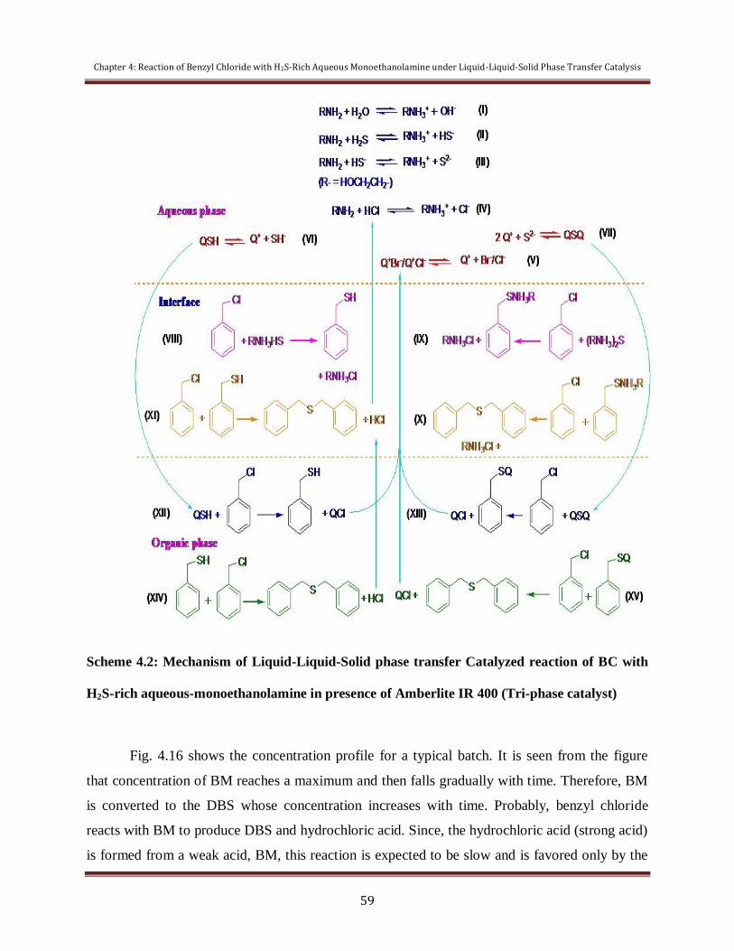
Chapter 4: Reaction of Benzyl Chloride with H2S-Rich Aqueous Monoethanolamine under Liquid-Liquid-Solid Phase Transfer Catalysis
59
Scheme 4.2: Mechanism of Liquid-Liquid-Solid phase transfer Catalyzed reaction of BC with
H2S-rich aqueous-monoethanolamine in presence of Amberlite IR 400 (Tri-phase catalyst)
Fig. 4.16 shows the concentration profile for a typical batch. It is seen from the figure
that concentration of BM reaches a maximum and then falls gradually with time. Therefore, BM
is converted to the DBS whose concentration increases with time. Probably, benzyl chloride
reacts with BM to produce DBS and hydrochloric acid. Since, the hydrochloric acid (strong acid)
is formed from a weak acid, BM, this reaction is expected to be slow and is favored only by the
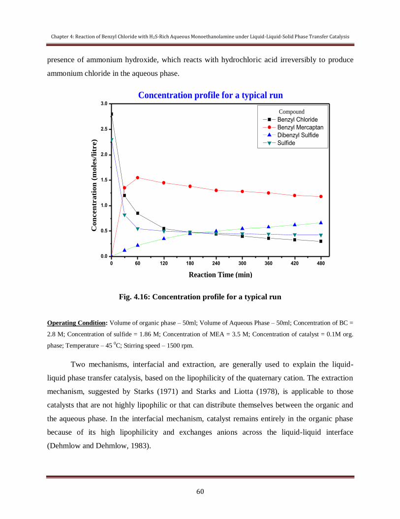
Chapter 4: Reaction of Benzyl Chloride with H2S-Rich Aqueous Monoethanolamine under Liquid-Liquid-Solid Phase Transfer Catalysis
60
presence of ammonium hydroxide, which reacts with hydrochloric acid irreversibly to produce
ammonium chloride in the aqueous phase.
0 60 120 180 240 300 360 420 480
0.0
0.5
1.0
1.5
2.0
2.5
3.0
Compound
Benzyl Chloride
Benzyl Mercaptan
Dibenzyl Sulfide
Sulfide
Co
ncen
tra
tio
n (
mo
les/
litr
e)
Reaction Time (min)
Concentration profile for a typical run
Fig. 4.16: Concentration profile for a typical run
Operating Condition: Volume of organic phase – 50ml; Volume of Aqueous Phase – 50ml; Concentration of BC =
2.8 M; Concentration of sulfide = 1.86 M; Concentration of MEA = 3.5 M; Concentration of catalyst = 0.1M org.
phase; Temperature – 45 0C; Stirring speed – 1500 rpm.
Two mechanisms, interfacial and extraction, are generally used to explain the liquid-
liquid phase transfer catalysis, based on the lipophilicity of the quaternary cation. The extraction
mechanism, suggested by Starks (1971) and Starks and Liotta (1978), is applicable to those
catalysts that are not highly lipophilic or that can distribute themselves between the organic and
the aqueous phase. In the interfacial mechanism, catalyst remains entirely in the organic phase
because of its high lipophilicity and exchanges anions across the liquid-liquid interface
(Dehmlow and Dehmlow, 1983).
Chapter 4: Reaction of Benzyl Chloride with H2S-Rich Aqueous Monoethanolamine under Liquid-Liquid-Solid Phase Transfer Catalysis
61
Ethanolammonium sulfide ((HOCH2CH2NH3)2S) and hydrosulfide (HOCH2CH2NH3SH)
are formed in the aqueous phase. In non-catalyzed reaction, these two species are expected to
react with BC at the aqueous-organic interface (as they are insoluble in organic phase). Based on
the product distribution, the mechanism of the non-catalytic reactions was represented by the
reactions VIII-XI of Scheme 4.2. The Ethanolammonium hydrosulfide and sulfide in the aqueous
phase non-catalytically react with organic phase benzyl chloride (C6H5CH2Cl) at the interface to
yield benzyl mercaptan (C6H5CH2SH) and Dibenzyl sulfide ((C6H5CH2)2S), respectively. The
nucleophilic substitution reactions are in general 2nd
order overall. The direct reaction of BC with
(RNH3)2S (R= HOCH2CH2) was therefore assumed to proceed through an intermediate,
C6H5CH2NH3R, which further reacts with C6H5CH2Cl to produce (C6H5CH2)2S. The
C6H5CH2SHreacts further with C6H5CH2Cl to produce (C6H5CH2)2S (reaction XI of Scheme
4.2). This conclusion was reached from the concentration profile of a typical batch (Fig. 4.14).
The reaction in presence of catalyst is expected to proceed through both catalytic and
non-catalytic pathway as shown in the Scheme 4.2. In the catalytic pathway, phase transfer
cation Q+ exchanges ion with ethanolammonium sulfide ((HOCH2CH2NH3)2S) and hydrosulfide
(HOCH2CH2NH3SH) to form ion-pairs Q+S
2-Q
+ and Q
+SH
- which, being organophilic in nature,
transfer to the organic phase and reactants with BC to form BM and DBS (reactions XII — XV
in Scheme 4.2).
4.3 Recycle and Reusability of Catalyst (Amberlite IR 400)
After the completion of the kinetic run, the agitation was stopped and the phases were
allowed to separate into three layers (L-L-S). When the phases were clearly separated, the
organic phase containing the product was removed. The reusability was found to be good up to
four uses and there was a loss in conversion during the fifth time since the amount of third phase
was less in comparison with the previous runs as shown in Fig.4.17.
After use the catalyst microsphere was filtered from the solution by the use of filter
paper. It was washed with acetone and water and was dried to remove the adsorbed substance.
The catalyst obtained was reused and the data obtained is shown in below figure.

Chapter 4: Reaction of Benzyl Chloride with H2S-Rich Aqueous Monoethanolamine under Liquid-Liquid-Solid Phase Transfer Catalysis
62
Fig. 4.17 shows the conversion of benzyl chloride with the cycle number. It can be seen
that after 4 cycles, the activity of tri phase catalyst Amberlite remains nearly unchanged. This
tells that Amberlite has got excellent reuse property and high stability.
1 2 3 4
0
10
20
30
40
50
60
70
80
90
100
% C
on
ve
rs
ion
of
Be
nzy
l C
hlo
rid
e
Cycle number
% Conversion of Benzyl Chloride
88%
84%
78%
68%
Fig.4.17: Effect of cycle number of reuse on the catalytic activity.
Operating condition:Volume of organic phase – 50ml, Volume of Aqueous Phase – 50ml, Concentration
of benzyl chloride – 2.8M, Sulfide concentration – 2.3M, MEA/H2S ratio–2.1, Temperature – 45 0C,
catalyst loading = 10%(w/v), Stirring speed – 1500 rpm.

CHAPTER 5
SUMMARY AND CONCLUSIONS

Chapter 5: Summary and Conclusions
64
Chapter 5
Summary and Conclusions
Abstract
This chapter summarizes the concluding remarks from the preceding chapter.
The present work carried out in this thesis leadsto the development of a state-of-the-
art process to produce value-added chemicals utilizing the H2S present in various byproduct
gas streams. In accordance with the present process, the H2S present in the gas streams can be
utilized to produce value-added products in two steps: (1) removal of H2S from gas stream by
conventional methods (alkanolamine-based processes), followed by (2) production of value-
added chemicals utilizing H2S-rich solution obtained from the first step of the process. Since
the removal of H2S by alkanolamines are well established and industrially practiced one, the
present work deals with a detailed study on the production of value-added chemicals utilizing
H2S-rich aqueous alkanolamine in the batch mode. The ammonia-based process is suitable
for the gas streams containing both NH3 and H2S because both the impurities can be removed
simultaneously in a single step, where as alkanolamines-based process can be used for gas
streams containing no ammonia because of its other advantages over the ammonia. The
strategy of the present process is schematically represented by Scheme 5.1, 5.2.
Scheme 5.1 Schematic representation of strategy of present process

Chapter 5: Summary and Conclusions
65
Scheme 5.2 Schematic representation of strategy of present process
The value-added chemicals produced in the present study are dibenzyl sulfide (DBS)
and benzyl mercaptan (BM) from benzyl chloride (BC). The reaction of benzyl chloride with
H2S-rich aqueous alkanolamines was conducted batch-wise in presence (Chapter 4) in
presence of an organic solvent (toluene) under Liquid-Liquid-Solid mode with a phase
transfer catalyst (PTC), Amberlite IR 400. The influence of various process variables (stirring
speed, catalyst loading, concentration of reactant, and temperature, alkanolamines
concentration, elemental sulfur loading) on the reaction rate, conversion, and selectivity was
studied. A suitable mechanism was established utilizing the effects of various parameters on
the reaction rate and conversion to explain the course of the reaction.
The reaction of benzyl chloride with H2S-rich aqueous MEA is of great industrial
relevance, which could lead to different products (DBS and BM) of commercial value. This
reaction was investigated in detail under liquid-liquid phase transfer catalysis conditions. One
can selectively prepare either DBS or BM using the same reagents only by selecting

Chapter 5: Summary and Conclusions
66
appropriate experimental conditions. A high MEA: sulfide mole ratio, high benzyl chloride
concentration, low ammonium sulfide volume, and long reaction time lead to the selective
preparation of DBS. On the other hand, opposite trend was observed for BM. With higher
benzyl chloride concentration and lower ammonium sulfide volume, the conversion of benzyl
chloride remains low with efficient sulfide utilization in the aqueous phase, whereas with
lower benzyl chloride concentration and higher ammonium sulfide volume, almost complete
conversion of benzyl chloride was observed although the utilization of sulfide in the aqueous
phase remains low.
The reaction is kinetically controlled with an apparent activation energy value of 40.7
KJ mol-1
. A change in temperature and catalyst concentration changes only the reaction rate
without significantly affecting the selectivity. The process involves a complex mechanism.
The existence of an ionic equilibrium among MEA, H2S, and water, producing sulfide and
hydrosulfide ions in the aqueous phase was established. The two active ion pairs (Q+
S−2
Q+
and Q+
SH−
) formed in the aqueous phase are first transferred to the organic phase and then
react with benzyl chloride to produce DBS and BM, respectively. DBS is also formed by the
reaction of BM and benzyl chloride.
The developed lab-scale process will be helpful in setting up indigenous
manufacturing facilities for organic sulfides, mercaptans and anilines. The present process
could be considered as an alternative to conventional processes (Claus or LO-CAT) because
it is possible to produce commercially important chemicals in a cost-effective way. The work
is also relevant to the global problem of pollution control caused by H2S, SO2 etc. and waste
minimization.
In the reaction of benzyl chloride with H2S-rich aqueous MEA, almost complete
sulfide utilization in the aqueous phase was observed under certain experimental conditions.
Therefore it needs no further treatment (tail gas treatment unit as in the Claus process) before
its reuse for the removal of H2S. Therefore, present process has enormous potential to be
considered as a viable alternative to conventional process (Claus or LO-CAT).

CHAPTER 6
SCOPE FOR FURTHER WORK

Chapter 6: Scope for Further Work
68
Chapter 6
Scope for Further Work
Abstract
This chapter recommends the possibility for future work based on the observations, results
and conclusions drawn from the present study. This chapter has been planned to identify the
areas where improvement can be done on the same systems to get better conversion and
selectivity and to get rid of some problems faced here. Also, how the present procedure can
be used to explore more in the field of phase transfer catalysis has been discussed.
6.1 Investigation of Mechanistic Pathways
As can be seen from chapter4, the mechanistic pathways shown for the reaction
ofbenzyl chloride with H2S-rich alkanolamine (Scheme 4.2) are based partly on some earlier
studies and partly from the data of the present studies. Aqueous phase can be analyzed to
know the presence of several species (Cl-, Br
-, HS
-, S
2-, Q
+ etc.) in it and then to quantify it to
get better insight into the mechanistic pathway in the aqueous phase of the triphasic reaction
system. This study will help to establish the reaction mechanism accurately, and then to
perform kinetic modelling.
6.2 Finding out Effect of other Parameters
The effect of pH of H2S-rich alkanolamine solution needs to beexplored. S2-
/HS- ratio
plays an important role in selectivity of benzyl mercaptan and benzyl sulfide (Schemes 4.2),
which in turn depends on the pH of the alkalinesolution. Effects of other anions as co-catalyst
and addition of alkali that can influence the reaction rate and selectivity of desired products
can also be tried.
6.3 Use of Other Aqueous Phase
The aqueous phase used in the present work is monoethanolamine which can absorb
both CO2 and H2S. Our present work is applicable for the stream containing H2S and CO2,
only if the aqueous phase is H2S selective.

Chapter 6: Scope for Further Work
69
6.4 Exploring the Possibilities of other Value-added Products
Some other industrially important sulfides or mercaptans can be
synthesizedselectively by using H2S-rich amines. H2S can also be converted to soluble
disulfide (S22-
) or bisulfide (HS-)preferentially to produce organic disulfide
(dibenzyldisulfide) or thiols selectively.
6.5 Large-scale Application of the Present Process
The present systems need to be tried out in a scaled-up set-up to check out the
performance of the presence process before applying for large-scale utilization. In ourpresent
study, separation and purification of the products have not been tried out. It canbe tried out
after carrying out reaction in bigger scale, separating the phases by separatingfunnel,
separating the organic liquid component by either distillation or other chemicalmethods
depending on the nature of components. Also identification of the products canbe done by
using different available techniques like NMR, FTIR or MS. Simultaneousidentification and
quantification can also be done in GC-MS.

REFERENCES
References
71
References
Akhnazarova, S.; Kafarov, V. Experiment Optimization in Chemistry and
ChemicalEngineering.Mir Publishers, Moscow, 1982.
Al-Baghli, N. A.; Pruess, S. A.; Yesavage, V. F.; Selim, M. S.A Rate-based Model forthe
Design of Gas Absorbers for the Removal of CO2 and H2S Using AqueousSolutions of
MEA and DEA.Fluid Phase Equilibria2001, 185, 31-43.
Asai, S.; Tajiri, H.; Hikita, H. Simultaneous Absorption of Hydrogen Sulfide andAmmonia
into Water.Gas Separation & Purification 1989, 3, 7-12.
Austgen, D. M.; Rochelle, G. T.; Peng, X.; Chen, C. Model of Vapor-Liquid Equilibriafor
Aqueous Acid Gas-Alkanolamine Systems Using the Electrolyte-
NRTLEquation.Industrial & Engineering Chemistry Research 1989, 28, 1060-1073.
Bally, A. P. Erdol und Kohle, Vol. 14, pp. 921-923, 1961.
Bandgar, B. P.; Sadavarte, V. S.; Pawar, Suchita G.; Kamble, V. T. Clean and
EfficientSynthesis of Thioethers under Mild and Nonaqueous Conditions. Indian
Journalof Heterocyclic Chemistry 2000, 10(2), 159-160.
Beutier, D.; Renon, H. Representation of NH3-H2S-H2O, NH3-CO2-H2O, and NH3-SO2-H2O
Vapor-Liquid Equilibria.Industrial & Engineering Chemistry ProcessDesign and
Development 1978, 17(3), 220-230.
Bhave, R. R.; Sharma, M. M. Kinetics of Two-Phase Reduction of Aromatic
NitroCompounds by Aqueous Solutions of Sodium Sulfides.Journal of
ChemicalTechnology and Biotechnology 1981, 31, 93-102.
Bittell, J. E.; Speier, J. L. Synthesis of Thiols and Polysulfides from Alkyl Halides,Hydrogen
Sulfide, Ammonia, and Sulfur.Journal of Organic Chemistry 1978,43(9), 1687-1689.
Blohm, C. L., and Riesenfeld, F. C.: 1955, US. Patent 2,712,978.
Bottoms, R. R., 1930, U.S. Patent 1,783,901; Re 1933, 18,958.
Box, G.E.P.; Hunter, W. G.; Hunter, J.S. Statistics for Experimenters.John Wiley andSons,
New York, 1978.
Box, G.E.P.; Wilson, K.B.On the experimental attainment of optimum conditions.J.Roy. Stat.
Soc. Ser. B. Method. 13 (1951) 1–45.
Bromley, L.A. Thermodynamic properties of strong electrolytes in aqueous solutionsAIChE
Journal 1973, 19 (2), 313–320.
Choi, J.; Yoon, N. M. Synthesis of Thiols via Palladium CatalyzedMethanolysis
ofThioacetateswithBorohydride Exchange Resin. Synthetic Communications1995a,
25(17), 2655-2663.

References
72
Choi, J.; Yoon, N. M. Direct Synthesis of Thiols from Halides and Epoxides
usingHydrosulfide Exchange Resin in Methanol.Synthesis 1995b, 4, 373-375.
Cline, E. L.; Reid, E. E.Some Derivatives of Ethylbenzene.Journal of AmericanChemical
Society 1927, 49, 3150-3156.
Dauben, W. G. Organic Reactions, John Wiley & Sons, Inc.: New York, 1973, Vol. 20,p455.
Dehmlow, E. V.; Dehmlow, S. S. Phase Transfer Catalysis, 2nd ed.,
VerlagChemieWeinheim, 1983.
Edwards, T.J., Newman, J., Prausnitz, J.M., 1975. Thermodynamics of aqueous
solutionscontaining volatile weak electrolytes.AIChE Journal 1975, 21 (2), 248–259.
Frazier, H. D. and Kohl, A. L. “Selective Absorption of H2S from Gas Streams,” Ind.Eng.
Chem. Vol. 42, 1950, pp. 2282-2292.
Gilman, H. Organic Syntheses. Collective volume 1, John Wiley & Sons, Inc.: NewYork,
1941, p-52.
Hamblin, R. Removal and Recovery of Sulfur from a Gas Stream Containing
HydrogenSulfide. Patent No. US3728441, 1973.
Han, X.; Zhou, R.; Lai, G.; Yue, B.; Zheng, X. Effect of Transition Metal (Cr, Mn, Fe,Co, Ni
and Cu) on the Hydrogenation Properties of Chloronitrobenzene OverPt/TiO2
Catalysts. Journal of Molecular Catalysis A: Chemical 2004, 209, 83-87.
Harvey, W. W.; Makrides, A.C. Process for Removing Hydrogen Sulfide and Ammoniafrom
Gaseous Streams.Patent No. US4192854, 1980.
Heather, J.B. Method for Preparation of Benzyl Mercaptan. U.S. patent No. 4740623,1988.
Hoffman, W. S.; Reid, E. E. Derivatives of Anthraquinone.Reactions of
AnthraquinoneSulfonic Acids with Mercaptans.Journal of American Chemical
Society 1923, 45,1831-1838.
Hojo, M.; Takagi, Y.; Ogata, Y. Kinetics of the Reduction of Nitrobenzene by
SodiumDisulfide. Journal of the American Chemical Society 1960, 82, 2459-2462.
Ido, T.; Susaki, T.; Jin, G.; Goto, S. Characteristics of Third Phase for Reaction of
BenzylChloride with Sodium Sulfide in Phase Transfer Catalytic System.
AppliedCatalysis A: General 2000, 201, 139–143.
Idoux, J. P.; Plain, W. Selective Reduction of Dinitrobenzenes.An Organic
LaboratoryExperiment.Journal of Chemical Education 1972, 49(2), 133.
Iranpoor, N.; Firouzabadi, H.; Shaterian, H. R. A New Approach to the Reduction
ofSulfoxides to Sulfides with 1,3-Dithiane in the Presence of Electrophilic Bromineas
Catalyst. Journal of Organic Chemistry 2002, 67(9), 2826-2830.
References
73
Isaacs, E. E.; Otto, F. D.; Mather, A. E. Solubility of Mixtures of H2S and CO2 in
aMonoethanolamine Solution at Low Partial Pressures. Journal of
ChemicalEngineering Data 1980, 25, 118-120.
Islam, M.A.; Sakkas,V.; Albanis,T.A. Application of statistical design of experimentwith
desirability function for removal of organophosphorus pesticide fromaqueous solution
by low-cost material, J. Hazard. Mater.2009, 170, 230-238.
Jwo, J.J. Phase Transfer Catalysis: Fundamentals and Selected Systems, Catalysis Reviews:
Science and Engineering 2003, vol. 45, Issue 3-4.
Kaewsichan, L.; Al-Bofersen, O.; Yesavage, V. F.; Selim, M. S. Predictions of thesolubility
of acid gases in monoethanolamine (MEA) and methyldiethanolamine(MDEA)
solutions using the electrolyte-UNIQUAC model. Fluid PhaseEquilibria2001, 183–
184, 159-171.
Kirk-OthmerEncyclopedia of Chemical Technology, John Wiley and Sons, New York,Vol-
22, P-267-289, 1983.
Kohl, A. L. “Selective H2S Absorption-A Review of Available PTO Processes,” Petrol.
Kohl, A.L.; Nielsen, R.B. Gas purification, Gulf Publishing Company Houston, Texas,1997.
Labat, Y. Synthesis of Benzyl Mercaptan. European Patent No.EP0337838, 1989.
Lakouraj, M. M.; Movassagh, B.; Fadaei, Z. Synthesis of Organic Sulfides via theZn/Alcl3
System in Aqueous Media.Synthetic Communications 2002, 32(8),1237-1242.
Lauwiner, M.; Rys, P.; Wissmann, J. Reduction of Aromatic Nitro Compounds
withHydrazine Hydrate in the Presence of an Iron Oxide Hydroxide Catalyst. I.
TheReduction of MonosubstitutedNitrobenzenes with Hydrazine Hydrate in the
Presence of Ferrihydrite.Applied Catalysis A: General 1998, 172, 141-148.
Lawson, J. D.; Garst, A. W. Gas Sweetening Data: Equilibrium Solubility of
HydrogenSulfide and Carbon Dioxide in Aqueous Monoethanolamine and
AqueousDiethanolamine Solutions. Journal of Chemical Engineering Data 1976,
21(1),20-30.
Lee, J. II; Otto, F. D.; Mather, A. E. Equilibrium in Hydrogen Sulfide-Monoethanolamine-
Water System.Journal of Chemical Engineering Data 1976,21(2), 207-208.
Lele, S.S., Bhave, R.R., Sharma, M.M. Fast and very low liquid–liquid reaction:
phasetransfer catalysis. Chemical Engineering Science 1983, 22, 765–773.
Maity, S.K.; Pradhan N.C; Patwardhan, A. V. Reaction of benzyl chloride withammonium
sulfide under liquid–liquid phase transfer catalysis: Reactionmechanism and kinetics,
Appl. Catal. A: Gen. 2006a, 250, 114–121.

References
74
Maity, S.K.; Pradhan N.C; Patwardhan, A. V. Kinetics of the reduction of nitrotoluenesby
aqueous ammonium sulfide under liquid–liquid phase transfer catalysis, Appl.Catal.
A: Gen. 2006b, 301, 251–258.
Maity, S.K.; Pradhan N.C; Patwardhan. Kinetics of Reduction of Nitrotoluenes by
H2SRichAqueous Ethanolamine, Ind. Eng. Chem. Res. 2006c, 45, 7767-7774.
Maity, S.K.; Pradhan N.C; Patwardhan. Reduction of o-nitroanisole to o-anisidinebyH2S-rich
aqueous diethanolamine:Anovel process for utilization ofH2S-ladengas streams,
Chem. Eng. Sc. 2007, 62, 805-813.
Manning, F. S., and Thompson, R. E. Oirfield Processing of Petroleum, Vol. one:Natural
Gas, Pennwell Publishing Co., Tulsa, OK, 1991.
Melville, J. B.; Goddard, J. D.A Solid-Liquid Phase-Transfer Catalysis in Rotating-
DiskFlow. Industrial &. Engineering Chemistry Research 1988, 27, 551-555.
Meindl, W. R.; Angerer, E. V.; Schonenberger, H.; Ruckdeschel, G. Benzylamines:Synthesis
and Evaluation of Antimycobacterial Properties. Journal of MedicinalChemistry
1984, 27, 1111-1118.
Meissner. R. E., 1983. “A Low Energy Process for Purifying Natural Gas,” Proceedingsof the
1983 Gas Conditioning Coilfereizce, University of Oklahoma, Norman,OK.
Meissner, R. E. and Wagner, U., 1983, Oil and Gas J., Feb. 7, pp. 55-58.
Miller, S. J.; Collier, T. R.; Wu, W. Efficient Reduction of Sulfoxides with 2,6-
Dihydroxypyridine. Tetrahedron Letters 2000, 41(20), 3781-3783.
Miller, F. E., and Kohl, A. L., “Selective Absorption of Hydrogen Sulfide,‟„Oil and GaJ.,
Vol. 51, April 27, pp. 175-183, 1953.
Mohammadpoor-Baltork, I.; Memarian, H. R.; Bahrami, K. 3-
CarboxypyridiniumChlorochromate-Aluminium Chloride-An efficient and
Inexpensive ReagentSystem for the Selective Oxidation of Sulfides to Sulfoxides and
Sulfones inSolution and Under Microwave Irradiation. Canadian Journal of
Chemistry 2005,83, 115-121.
Montgomery, D.C. Design and Analysis of Experiments, fifth ed., John Wiley and Sons,New
York, USA, 2001.
Movassagh, B.; Mossadegh, A. Reductive Cleavage of S-S Bond by Zn/AlCl3 System:
ANovel Method for the Synthesis of Sulfides from Alkyl Tosylates and
Disulfides.Synthetic Communications 2004a, 34(13), 2337-2343.
Movassagh, B.; Mossadegh, A. Reductive Cleavage of S-S Bond by Zn/Alcl3 System.ANovel
Method for the Synthesis of Sulfides from Alkyl Tosylates and Disulfides.Synthetic
Communications 2004b, 34(9), 1685-1690.

References
75
Murray, M. J.; Waters, D. E. Ammonium Chloride-Sodium Sulfide Solutions for
OrganicNitro Reductions and for Inorganic Qualitative Analysis.Journal of
AmericanChemical Society 1938, 60, 2818-2819.
Myres, R.H.; Montgomery, D.C. Response Surface Methodology: Process and
ProductOptimization Using Designed Experiments, 2nd ed., R.H. Myres,
D.C.Montgomery (Eds.), John Wiley and Sons, New York, 2002.
Naik, S. D.; Doraiswamy, L. K. Mathematical Modeling of Solid-Liquid Phase
TransferCatalysis.Chemical Engineering Science 1997, 52(24), 4533-4546.
Neumann, R.; Sasson, Y. Mechanism of Base-Catalyzed Reactions in Phase-TransferSystems
with Poly (ethy1ene glycols) as Catalysts. The Isomerization ofAllylanisole.The
Journal of Organic Chemistry 1984, 49, 3448-3451.
Niswander, R. H., Edwards, D. J., DuPart, M. S., and Tse, J. P.”A More EnergyEfficient
Product for Carbon Dioxide Separation,” Proceedings of the 42nd
Annual Laurance
Reid Gas Conditioning Conference, University of Oklahoma,Norman, OK, March 21,
1992.
Pearce, R. L., and Wolcott, R. A. “Basic Considerations in Acid Gas Removal,”presented at
the AIChE Annual Meeting, New Orleans, LA, April 6-10, 1986.
Plummer, M.A. Process for Recovering Sulfur and Hydrogen from Hydrogen Sulfide.Patent
No. WO9412431, 1994.
Plummer, M.A.; Beazley, P.M. Conversion of Hydrogen Sulfide to Sulfur and
Hydrogen.Patent Number US4592905, 1986.
Plummer, M.A.; Zimmerman, Jr Carle C. Hydrocarbon Desulfurization
Process.PatentNumber US4581128, 1986.
Pradhan, N. C.; Sharma, M. M. Kinetics of Reactions of Benzyl Chloride/p-
ChlorobenzylChloride with Sodium Sulfide: Phase-Transfer Catalysis and the Role of
theOmega Phase. Industrial & Engineering Chemistry Research 1990, 29, 1103-1108.
Pradhan, N. C.; Sharma, M. M. Solid-Liquid Reactions Catalyzed by Alumina and
IonExchange Resin: Reactions of Benzyl Chloride/ p-Chlorobenzyl Chloride
withSolid Sodium Sulfide. Industrial & Engineering Chemistry Research 1992a,
31,1610-1614.
Robin, P. Method for Removing Hydrogen Sulfide From Natural Gas. Patent
No.WO9964137, 1999.
Rumpf, B.; Kamps, Á. P.; Sing, R.; Maurer, G. Simultaneous Solubility of Ammonia
andHydrogen Sulfide in Water at Temperatures from 313 K to 393 K. Fluid
PhaseEquilibria1999, 158–160, 923–932.
Satrio, J. A. B.; Doraiswamy, L. K. Phase Transfer Catalysis: A New RigorousMechanistic
Model for Liquid-Liquid Systems. Chemical Engineering Science2002, 57, 1355-

References
76
1377.Scott, W. W. Standard Methods of Chemical Analysis, Van Nostrand: New
York, 6th ed.,Vol. IIA, p 2181, 1966.
Sidi-Boumedine, R.; Horstmann, S.; Fischer, K.; Provost, E.; Fürst, W.; Gmehling,
J.Experimental determination of hydrogen sulfide solubility data in
aqueousalkanolamine solutions.Fluid Phase Equilibria2004, 218, 149-155.
Starks, C. M. Phase Transfer Catalysis. I. Heterogeneous Reactions Involving AnionTransfer
by Quaternary Ammonium and Phosphonium Salts. Journal of theAmerican Chemical
Society 1971, 93, 195-199.
Starks, C. M.; Liotta, C. L. Phase-Transfer Catalysis Principles and Techniques,Academic:
New York, 1978.
Starks, C.M., Liotta, C.L., Halpern, M. Phase Transfer Catalysis. Chapman & Hall,
NewYork, USA, 1994.
Thomas, D.E. Composition and Method for Sweetening Hydrocarbons. Patent
No.WO9007467, 1990.
Thomas, J. C. “Improved Selectivity Achieved with UCARSOL Solvent,” Proceedingsof the
Laurance Reid Gas Conditioning Conference, University of Oklahoma,Norman, OK,
March, 1988.
Tu, W.; Liu, H.; Tang, Y. The Metal Complex Effect on the Selective Hydrogenation ofm-
and p-Chloronitrobenzene Over PVP-Stabilized Platinum Colloidal Catalysts.Journal
of Molecular Catalysis A: Chemical 2000, 159, 115-120.
Vallée, G.; Mougin, P.; Jullian, S.; Fürst, W. Representation of CO2 and H2S Absorptionby
Aqueous Solutions of Diethanolamine Using an Electrolyte Equation of
State.Industrial & Engineering Chemistry Research 1999, 38, 3473-3480.
Varma, R. S.; Saini, R. K.; Meshram, H. M. Selective Oxidation of Sulfides to
SulfoxidesandSulfones by Microwave Thermolysis on Wet Silica-Supported
SodiumPeriodate. Tetrahedron Letters 1997, 38 (37), 6525-6528.
Volkov, A.G.; Deamer, D. W. Liquid Liquid Interfaces, CRC Press: New York, 1996.
Volkov, A.G. Interfacial Catalysis, CRC Press: New York, 2002.
Wang, D. H.; Weng, H. S. Preliminary Study on the Role Played by the Third LiquidPhase in
Phase Transfer Catalysis.Chemical Engineering Science 1988, 43, 2019-2024.
Wang, M.L., Chang, S.W. Model of the kinetics of synthesizing formaldehyde acetals
byphase-transfer catalysis. Industrial & Engineering Chemistry Research 1994,
33,1606–1611.
Wang, M.L; Tseng, Y.H. Phase Transfer Catalytic Reaction of n-Bromobutane andSodium
Sulfide in a Two-Phase Solution and its Kinetics. J. Molecular CatalysisA: Chemical
2003, 203, 79–93.

References
77
Wang, M.L., Tseng, Y.H. Phase-transfer catalytic reaction of dibromo-o-xylene and 1-
butanol in two-phase solution.Journal of Molecular Catalysis A: Chemical2002a,
179, 17–26.
Wang, M.L., Tseng, Y.H. Kinetic model for synthesizing 4,4-diethanoxy biphenyl byphase
transfer catalysis. Journal of Molecular Catalysis A: Chemical 2002b, 188,51–61.
Wang, M.L., Wu, H.S. Kinetic and mass transfer studies of a sequential reaction by
phasetransfer catalysis. Chemical Engineering Science 1991, 46 (2), 509–517.
Wang, M.L., Yang, H.M. Dynamics of phase transfer catalyzed reaction for the allylationof
2,4,6-tribromophenol. Chemical Engineering Science 1991a, 46 (2), 619–627.
Wang, M.L., Yang, H.M. Simplified dynamic model for the allylation of 2,4,6-
tribromophenol by phase-transfer catalysis. Industrial & Engineering
ChemistryResearch 1991b, 30, 631–635.
Weber, W. P., Gokel, G. W. Phase Transfer Catalysis in Organic Syntheses.Springer Verlag,
NewYork, 1977.
Weiland, R. H.; Chakravarty, T.; Mather, A. E. Solubility of Carbon Dioxide andHydrogen
Sulfide in Aqueous Alkanolamines.Industrial & EngineeringChemistry Research
1993, 32, 1419-1430.
Wu, H.S., Fang, T.R., Meng, S.S., Hu, K.H. Equilibrium and extraction of quaternary saltin
an organic solvent/alkaline solution: effect of NaOH concentration. Journal
ofMolecular Catalysis A: Chemical 1998, 136, 135–146.
Wu, H.S. Phase-plane modeling of a liquid–liquid phase transfer catalyzed reaction.Industrial
& Engineering Chemistry Research 1993, 32, 1323–1327.
Wu, H.S., 1996. Mathematical modeling for liquid–liquid phase-transfer catalysis.Chemical
Engineering Science 51 (5), 827–830.
Yadav, G. D.; Lande, S. V. Liquid-liquid-liquid phase transfer catalysis: A novel andgreen
concept for selective reduction of substituted nitroaromatics. AdvancedSynthesis &
Catalysis 2005, 347, 1235-1241.
Yadav, G. D.; Lande, S. V. Intensification of Rates and Selectivity Using Tri-liquidversus Bi-
liquid Phase Transfer Catalysis: Insight into Reduction of 4-Nitro-oxylenewith
Sodium Sulfide. Industrial & Engineering Chemistry Research 2007,46, 2951-2961.
Yadav, G. D.; Naik, S. S. Novelties of Liquid-Liquid-Liquid Phase Transfer
Catalysis:Alkoxylation of p-Chloronitrobenzene. Catalysis Today 2001, 66, 345-354.
Yadav, G.D., Jadhav, Y.B., 2003a. Kinetics and modeling of liquid–liquid phase
transfercatalysed synthesis of p-chlorophenyl acetonitrile: role of co-catalyst
inintensification of rates and selectivity. Journal of Molecular Catalysis A:Chemical
2003a, 192, 41–52.

References
78
Yadav, G. D.; Jadhav, Y. B.; Sengupta, S. Novelties of Kinetics and Mechanism ofLiquid–
Liquid Phase Transfer Catalyzed Reduction of p-Nitroanisole to p-Anisidine.
Chemical Engineering Science 2003b, 58, 2681 - 2689.
Yadav, G. D.; Jadhav, Y. B.; Sengupta, S. Selectivity Engineered Phase TransferCatalysis in
the Synthesis of Fine Chemicals: Reactions of p-Chloronitrobenzenewith Sodium
Sulphide. Journal of Molecular Catalysis A: Chemical 2003c, 200,117-129.
Yadav, G. D.; Reddy, C. A. Kinetics of the n-Butoxilation of p-Chloronitrobenzene
underLiquid-Liquid-Liquid Phase Transfer Catalysis. Industrial &
EngineeringChemistry Research 1999, 38 (6), 2245-2253.
Yadav, G. D.; Sharma, M. M. Kinetics of Reactions of Benzyl Chloride with
SodiumAcetate/Benzoate: Phase Transfer Catalysis in Solid-Liquid System. Industrial
&Engineering Chemistry Process Design and Development 1981, 20, 385-390.Yang,
H.M., Lin, C.L. Phase-transfer catalyzedbenzylation of sodium benzoate usingaliquat
336 as catalyst in liquid–liquid system. Journal of Molecular Catalysis A:Chemical
2003, 206, 67–76.
Yuan, X.; Liu, J.; Zeng, G.; Shi, J.; Huang, G. Optimization of conversion of wasterapeseed
oil with high FFA to biodiesel using response surface methodology,Renew. Energy
2008, 33, 1678-1684.