Embed Size (px)
Citation preview

Faculty of Civil Engineering
Reinforced Concrete I. / Beton Armat I.
Dr.ing. Nagy-György T.
Dr. NAGY-GYÖRGY TamásAssociate Professor
E-mail: [email protected]
Tel:+40 256 403 935
Web:http://www.ct.upt.ro/users/TamasNagyGyorgy/index.htm
Office:A219

Faculty of Civil EngineeringDr.ing. Nagy-György T. 2
Reinforced Concrete I. / Beton Armat I.
6.1 DESIGN CHARACTERISTICS OF CONCRETE
6.2 DESIGN CHARACTERISTICS OF STEEL REINFORCEMENT

Faculty of Civil EngineeringDr.ing. Nagy-György T. 3
Reinforced Concrete I. / Beton Armat I.
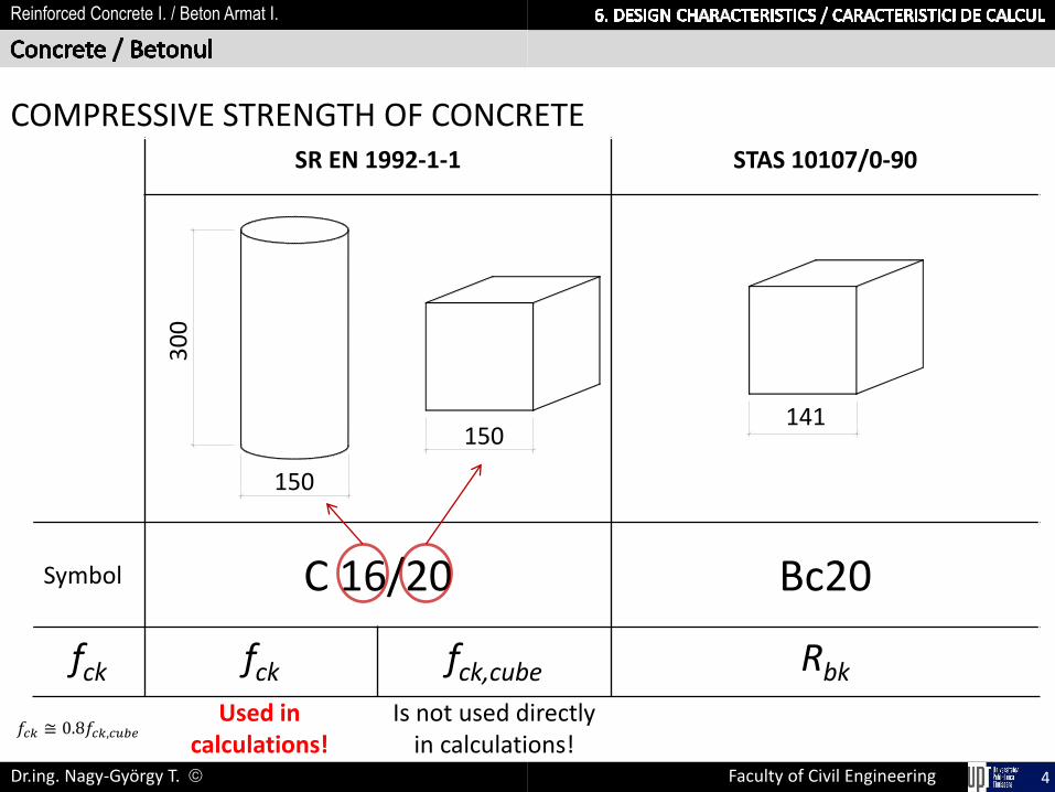
The compressive strength of concrete is denoted by concretestrength classes which relate to the characteristic (5%) cylinderstrength fck , or the cube strength fck,cube , determined at 28 days.
C16/20
freq
uen
cy
𝑓𝑘
p=5%
1.64Normal distribution curve of concrete strength
Strength class of concrete is a characteristicstrength, because represents the value belowwhich 5% of values are expected to fall.
𝑓𝑐𝑦𝑙 = (0.87 − 0.002𝑓𝑐𝑢𝑏)𝑓𝑐𝑢𝑏
𝑓𝑘 = (1 − 𝑡𝑐𝑣)𝑓𝑚𝑒𝑑
𝑐𝑣 = 15%
𝑡 = 1.64 for p=5% and n120
𝑓𝑚𝑒𝑑 𝑓
Faculty of Civil EngineeringDr.ing. Nagy-György T. 4
Reinforced Concrete I. / Beton Armat I.
SR EN 1992-1-1 STAS 10107/0-90
Symbol C 16/20 Bc20
fck fck fck,cube Rbk
150
150141
30
0
Used in calculations!
Is not used directly in calculations!
COMPRESSIVE STRENGTH OF CONCRETE
𝑓𝑐𝑘 ≅ 0.8𝑓𝑐𝑘,𝑐𝑢𝑏𝑒

Faculty of Civil EngineeringDr.ing. Nagy-György T. 5
Reinforced Concrete I. / Beton Armat I.
COMPRESSIVE STRENGTH OF CONCRETE
𝑓𝑐𝑘 = 𝑓𝑐𝑘,𝑐𝑦𝑙
THE MEAN CONCRETE COMPRESSIVE STRENGTH
𝑓𝑐𝑚 = 𝑓𝑐𝑘 + 8(𝑀𝑃𝑎)
150
30
0

Faculty of Civil EngineeringDr.ing. Nagy-György T. 6
Reinforced Concrete I. / Beton Armat I.
COMPRESSIVE STRENGTH OF CONCRETE AT AN AGE t depends on:• type of cement• temperature• curing conditions
𝑓𝑐𝑘 𝑡 = 𝑓𝑐𝑚 𝑡 − 8(𝑀𝑃𝑎) for 3 < t < 28 days
𝑓𝑐𝑘 𝑡 = 𝑓𝑐𝑘 for t ≥ 28 days
𝑓𝑐𝑚 𝑡 = 𝛽𝑐𝑐(𝑡)𝑓𝑐𝑚 with 𝛽𝑐𝑐 𝑡 = 𝑒𝑥𝑝 𝑠 1 −28
𝑡
1/2
where𝑓𝑐𝑚 𝑡 - mean concrete compressive strength at an age of t days𝛽𝑐𝑐(𝑡)- coefficient which depends on the age of the concrete t𝑠 - coefficient which depends on the type of cement

Faculty of Civil EngineeringDr.ing. Nagy-György T. 7
Reinforced Concrete I. / Beton Armat I.
TENSILE STRENGTH OF CONCRETE
The tensile strength of concrete 𝑓𝑐𝑡 refers to the highest stressreached under concentric tensile loading.
The usual test is splitting of acylindrical specimen.
Where the tensile strength is determined as the splitting tensilestrength (𝑓𝑐𝑡,𝑠𝑝) the approximate value of the axial tensile strength
may be taken as:
𝑓𝑐𝑡 = 0.9𝑓𝑐𝑡,𝑠𝑝

Faculty of Civil EngineeringDr.ing. Nagy-György T. 8
Reinforced Concrete I. / Beton Armat I.
TENSILE STRENGTH OF CONCRETE
Average tensile strength is obtained from relation:
𝑓𝑐𝑡𝑚 = 0.3𝑓𝑐𝑘2/3
Other values of the characteristic tensile strength, defined by thefractal of 5% and 95%:
𝑓𝑐𝑡𝑘,0.05 = 0.7𝑓𝑐𝑡𝑚
𝑓𝑐𝑡𝑘,0.95 = 1.3𝑓𝑐𝑡𝑚
5% 95%

Faculty of Civil EngineeringDr.ing. Nagy-György T. 9
Reinforced Concrete I. / Beton Armat I.
TENSILE STRENGTH OF CONCRETE at an age t
is strongly influenced by curing and drying conditions as well as bythe dimensions of the structural members
𝑓𝑐𝑡𝑚 𝑡 = 𝛽𝑐𝑐(𝑡)𝛼 ∙ 𝑓𝑐𝑡𝑚
where𝛼 = 1 for t < 28 days𝛼 = 2/3 for t ≥ 28 days

Faculty of Civil EngineeringDr.ing. Nagy-György T. 10
Reinforced Concrete I. / Beton Armat I.
DESIGN COMPRESSIVE AND TENSILE STRENGTHS
The value of the design compressive strength is defined as
𝑓𝑐𝑑 = 𝛼𝑐𝑐𝑓𝑐𝑘
𝛾𝑐=
𝑓𝑐𝑘
𝛾𝑐 𝑓𝑐𝑑 =
𝑓𝑐𝑘
𝛾𝑐
The value of the design tensile strength is defined as
𝑓𝑐𝑡𝑑 = 𝛼𝑐𝑡𝑓𝑐𝑡𝑘,0.05
𝛾𝑐=
𝑓𝑐𝑡𝑘,0.05
𝛾𝑐 𝑓𝑐𝑡𝑑 =
𝑓𝑐𝑡𝑘,0.05
𝛾𝑐
𝛼𝑐𝑐 , 𝛼𝑐𝑡 - coefficient taking account of long term effects on the compressive/tensile strength and ofunfavourable effects resulting from the way the load is applied. Recommended value is = 1.0.
Faculty of Civil EngineeringDr.ing. Nagy-György T. 11
Reinforced Concrete I. / Beton Armat I.
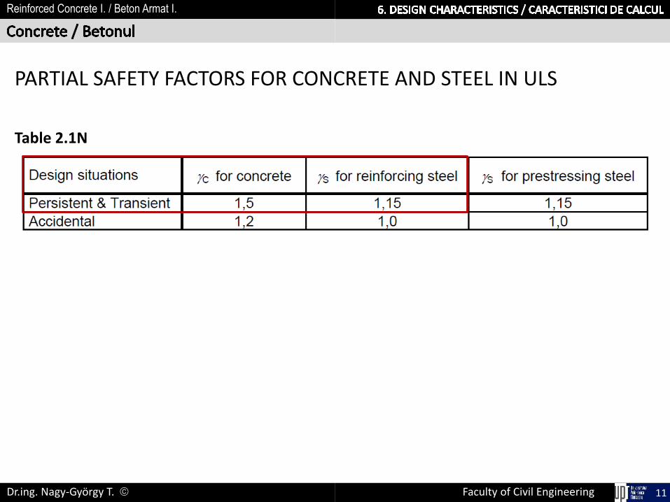
PARTIAL SAFETY FACTORS FOR CONCRETE AND STEEL IN ULS
Table 2.1N

Faculty of Civil EngineeringDr.ing. Nagy-György T. 12
Reinforced Concrete I. / Beton Armat I.
Characteristic compressive cylinder strength of concrete
Characteristic compressive cube strength of concrete
Mean value of concrete cylinder compressive strength
Mean value of axial tensile strength of concrete
Secant modulus of elasticity of concreteCompressive strain in the concrete at the peak stress fc
Ultimate compressive strain in the concrete
Strain at reaching the maximum strength in concrete
Ultimate strain in concrete
Exponent in formula 3.17
Strain at maximum strength in concrete (fig . 3.4)
Ultimate strain in concrete (fig . 3.4)
Characteristic tensile strength of concrete with 5% probabil.
Characteristic tensile strength of concrete with 95% probabil.

Faculty of Civil EngineeringDr.ing. Nagy-György T. 13
Reinforced Concrete I. / Beton Armat I.
The modulus of elasticity of a concrete (𝐸𝑐𝑚)is controlled by the moduli of elasticity of its components. secant value between 𝜎𝑐 = 0 and 0.4𝑓𝑐𝑚
𝐸𝑐𝑚 = 22000(𝑓𝑐𝑚/10)0.3
Variation of the modulus of elasticity with time:
𝐸𝑐𝑚 𝑡 = 𝑓𝑐𝑚(𝑡)/𝑓𝑐𝑚0.3 ∙ 𝐸𝑐𝑚
Valid concretes with quartzite aggregates!For limestone aggregates should be reduced by 10%For sandstone aggregates should be reduced by 30% For basalt aggregates should be increased by 20%.

Faculty of Civil EngineeringDr.ing. Nagy-György T. 14
Reinforced Concrete I. / Beton Armat I.
Poisson’s ratio may be taken equal to
ν = 0,2 for uncracked concreteν = 0 for cracked concrete
The linear coefficient of thermal expansion may be taken equal to10⋅10-6 K-1.

Faculty of Civil EngineeringDr.ing. Nagy-György T. 15
Reinforced Concrete I. / Beton Armat I.
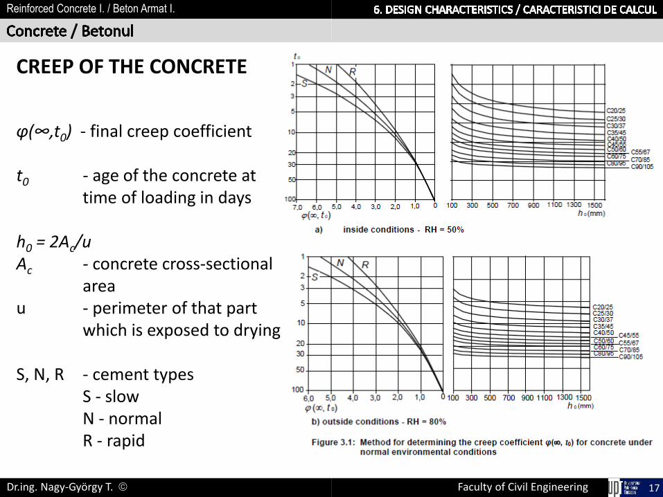
CREEP OF THE CONCRETE
CEMENT HYDRATION CRISTALS (elastic behavior) & GELS (viscous behavior)
P = const.
t = 0
e
P = const.
t = t
creep
e
creep
Creep coefficient

Faculty of Civil EngineeringDr.ing. Nagy-György T. 16
Reinforced Concrete I. / Beton Armat I.
CREEP OF THE CONCRETE
Depends on the:
- Humidity of the environment: RH (%)
- Type of the cement: (curing rate): S ‐ slow; N - normal; R ‐ rapid- Concrete strength: fck
- Age of concrete at the time of loading: t0
- Dimensions of the element: h0 = 2Ac/u - notional size (mm) of the cross-sectionAc – concrete cross-sectional areau - the perimeter of that part which is exposed to drying
Creep is also influenced by the maturity of the concrete when the load is firstapplied and depends on the duration and magnitude of the loading.
Creep coefficient φ(t,t0) is obtained from tables if 𝜎𝑐 ≤ 0.45𝑓𝑐𝑘(𝑡0)
↔ linear creep is expected
Faculty of Civil EngineeringDr.ing. Nagy-György T. 17
Reinforced Concrete I. / Beton Armat I.
φ(∞,t0) - final creep coefficient
t0 - age of the concrete attime of loading in days
h0 = 2Ac/uAc - concrete cross-sectional
areau - perimeter of that part
which is exposed to drying
S, N, R - cement typesS - slowN - normalR - rapid
CREEP OF THE CONCRETE

Faculty of Civil EngineeringDr.ing. Nagy-György T. 18
Reinforced Concrete I. / Beton Armat I.
t 0 (z
ile)
(∞, t0)
- choose of environmental conditions(RH=50% inside; RH=80% outside)- Choose of cement type (N, R, S)
- Choose of concrete class- Calculus of h0
Cf ck
/ f ck
,cu
be
h0=2Ac /u
Creep of concrete depends on humidity of the environment, dimensions of the element and compositionof concrete + age of concrete at the time of loading and duration and magnitude of the loading.
CREEP OF THE CONCRETE - SR EN 1991-1-1

Faculty of Civil EngineeringDr.ing. Nagy-György T. 19
Reinforced Concrete I. / Beton Armat I.
Creep of concrete depends on humidity of the environment, dimensions of the element and compositionof concrete + age of concrete at the time of loading and duration and magnitude of the loading.
CREEP OF THE CONCRETE - SR EN 1991-1-1
t 0 (d
ays
)
(∞, t0)
1. t0 - age of the concrete at time of loading(in days)
2. Secant
3. h0 [mm]
Cf ck
/ f ck
,cu
be
h0=2Ac /u
1
2
3
4
5

Faculty of Civil EngineeringDr.ing. Nagy-György T. 20
Reinforced Concrete I. / Beton Armat I.
The creep deformation of concrete 𝜀𝑐𝑐 ∞, 𝑡0 at time 𝑡 = ∞ for aconstant compressive stress 𝜎𝑐 applied at the concrete age t0 is:
𝜀𝑐𝑐 ∞, 𝑡0 = 𝜑 ∞, 𝑡0 ∙ (𝜎𝑐/𝐸𝑐)
𝐸𝑐 = 1,05𝐸𝑐𝑚
The effective modulus of elasticity of concrete under long term loads:
𝐸𝑐,𝑒𝑓𝑓 =𝐸𝑐𝑚
1 + 𝜑(∞, 𝑡0)
Ec

Faculty of Civil EngineeringDr.ing. Nagy-György T. 21
Reinforced Concrete I. / Beton Armat I.
SHRINKAGE OF THE CONCRETE
The total shrinkage strain 𝜀𝑐𝑠 is composed of two components:
1. the drying shrinkage strain 𝜀𝑐𝑑 - develops slowly, since it is a functionof the migration of the water through the hardened concrete.
2. the autogenous shrinkage strain 𝜀𝑐𝑎 - develops during hardening ofthe concrete: the major part therefore develops in the early days aftercasting. Autogenous shrinkage is a linear function of the concretestrength.
𝜀𝑐𝑠 = 𝜀𝑐𝑑 + 𝜀𝑐𝑎

Faculty of Civil EngineeringDr.ing. Nagy-György T. 22
Reinforced Concrete I. / Beton Armat I.
Drying shrinkage strain at an age t
𝜀𝑐𝑑 𝑡 = 𝛽 𝑡, 𝑡𝑠 ∙ 𝑘ℎ ∙ 𝜀𝑐𝑑,0
kh = coefficient depending on the notional size h0
h0 = 2Ac/u
t - age of the concrete at the moment considered, in daysts - the age of the concrete (days) at the beginning of drying shrinkage (or swelling)

Faculty of Civil EngineeringDr.ing. Nagy-György T. 23
Reinforced Concrete I. / Beton Armat I.
Autogenous shrinkage 𝜀𝑐𝑎
𝜀𝑐𝑎 𝑡 = 𝛽𝑎𝑠 𝑡 ∙ 𝜀𝑐𝑎(∞)
Where
𝜀𝑐𝑎 ∞ = 2.5(𝑓𝑐𝑘 − 10)10−6
𝛽𝑎𝑠 𝑡 = 1 − 𝑒𝑥𝑝(−0.2𝑡0.5)
Faculty of Civil EngineeringDr.ing. Nagy-György T. 24
Reinforced Concrete I. / Beton Armat I.
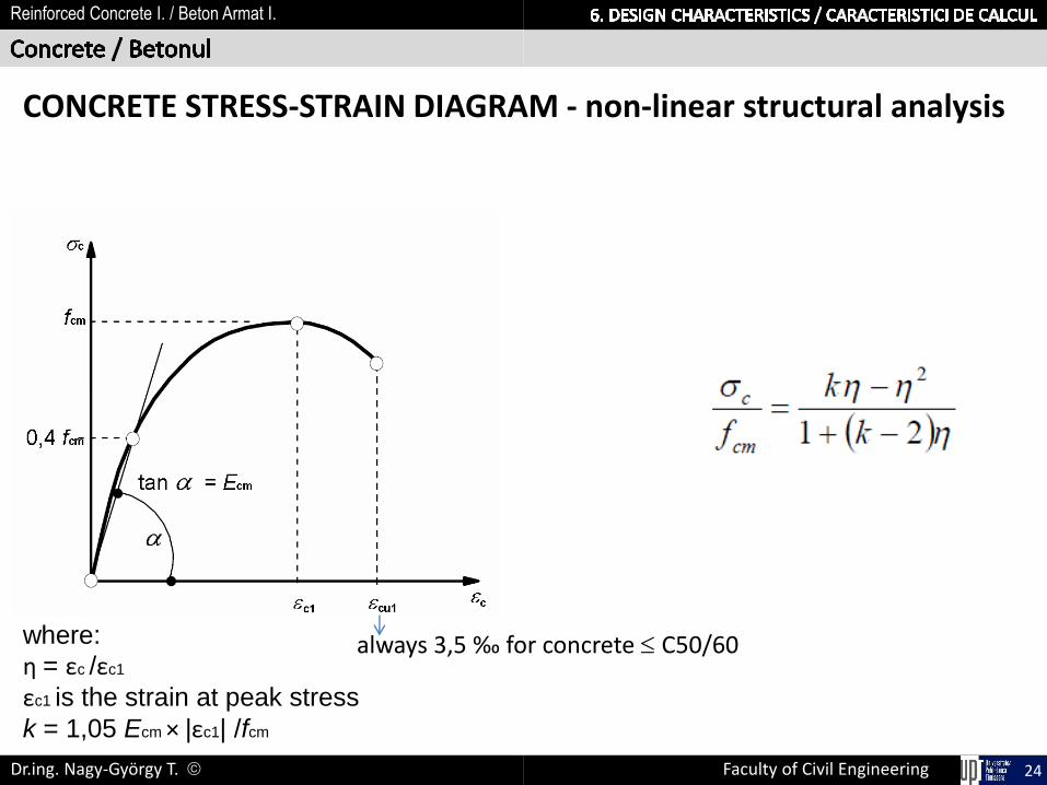
CONCRETE STRESS-STRAIN DIAGRAM - non-linear structural analysis
where:
η = εc /εc1
εc1 is the strain at peak stress
k = 1,05 Ecm × |εc1| /fcm
always 3,5 ‰ for concrete C50/60

Faculty of Civil EngineeringDr.ing. Nagy-György T. 25
Reinforced Concrete I. / Beton Armat I.
CONCRETE STRESS-STRAIN DIAGRAM - design of cross-sections
1. Parabola-rectangle diagram for concrete under compression
2‰ 3.5‰
Valid for ≤ C50/60
εs
εcu2 fcd
n = 2 for C50/60
Fs

Faculty of Civil EngineeringDr.ing. Nagy-György T. 26
Reinforced Concrete I. / Beton Armat I.
CONCRETE STRESS-STRAIN DIAGRAM - design of cross-sections
2. Bi-linear stress-strain relation
εs
εcu3 fcd
1.73‰ 3.5‰
Valid for ≤ C50/60
Fs

Faculty of Civil EngineeringDr.ing. Nagy-György T. 27
Reinforced Concrete I. / Beton Armat I.
CONCRETE STRESS-STRAIN DIAGRAM - design of cross-sections
2. Bi-linear stress-strain relation simplified (rectangular) stressdistribution
Valid for ≤ C50/60
εcu ηfcd
xλx
In usual casesλ = 0,8η = 1,0
Fsεs

Faculty of Civil EngineeringDr.ing. Nagy-György T. 28
Reinforced Concrete I. / Beton Armat I.
CONCRETE STRESS-STRAIN DIAGRAMS
straindiagram
stressdiagram
stress block diagram
simplifiedstress diagram

Faculty of Civil EngineeringDr.ing. Nagy-György T. 29
Reinforced Concrete I. / Beton Armat I.
CONFINED CONCRETE increasing compressive strength of concrete by creating triaxial stress
Confined concreteTUBE
Confined concreteSPIRAL REINFORCEMENT
Internal forces

Faculty of Civil EngineeringDr.ing. Nagy-György T. 30
Reinforced Concrete I. / Beton Armat I.
CONFINED CONCRETE increasing compressive strength of concrete by creating triaxial stress Increasing the characteristic compressive stresses to fck,c and the deformations to εcu2,c
1
1
εc
c
fck
fcd
εcu2εc2

Faculty of Civil EngineeringDr.ing. Nagy-György T. 31
Reinforced Concrete I. / Beton Armat I.
CONFINED CONCRETE increasing compressive strength of concrete by creating triaxial stress Increasing the characteristic compressive stresses to fck,c and the deformations to εcu2,c
1 = fck,c
1 = fck,c
3 = 2
εc
c
fck
fcd
εcu2εc2
2
εc2,c εcu2,c
fck,c
fcd,c
σ2 = σ3 – compressive stresses, perpendicular to element axis

Faculty of Civil EngineeringDr.ing. Nagy-György T. 32
Reinforced Concrete I. / Beton Armat I.
CONFINED CONCRETE increasing compressive strength of concrete by creating triaxial stress Increasing the characteristic compressive stresses to fck,c and the deformations to εcu2,c
1 = fck,c
1 = fck,c
3 = 2
εc
c
fck
fcd
εcu2εc2
2
εc2,c εcu2,c
fck,c
fcd,c
σ2 = σ3 – compressive stresses, perpendicular to element axis

Faculty of Civil EngineeringDr.ing. Nagy-György T. 33
Reinforced Concrete I. / Beton Armat I.
CONFINED CONCRETE increasing compressive strength of concrete by creating triaxial stress Increasing the characteristic compressive stresses to fck,c and the deformations to εcu2,c
1 = fck,c
1 = fck,c
3 = 2
εc
c
fck
fcd
εcu2εc2
2
εc2,c εcu2,c
fck,c
fcd,c
σ2 = σ3 – compressive stresses, perpendicular to element axis

Faculty of Civil EngineeringDr.ing. Nagy-György T. 34
Reinforced Concrete I. / Beton Armat I.
CONFINED CONCRETE increasing compressive strength of concrete by creating triaxial stress Increasing the characteristic compressive stresses to fck,c and the deformations to εcu2,c
εc
c
fck
fcd
εcu2εc2εc2,c εcu2,c
fck,c
fcd,c
σ2 = σ3 – compressive stresses, perpendicular to element axis
50mm
b) a)
250mm
250mm
stirrup
c)
250mm

Faculty of Civil EngineeringDr.ing. Nagy-György T. 35
Reinforced Concrete I. / Beton Armat I.
6.1 DESIGN CHARACTERISTICS OF CONCRETE
6.2 DESIGN CHARACTERISTICS OF STEEL REINFORCEMENT
Faculty of Civil EngineeringDr.ing. Nagy-György T. 36
Reinforced Concrete I. / Beton Armat I.
PERFORMANCE CRITERIA FOR STEEL REINFORCEMENTS
Strength criteria:
- Characteristic yield strength fyk or f0,2k
- Upper limit of the strength fy,max ≤ 1,3 fyk
- Characteristic tensile strength (ftk)
- Fatigue
Faculty of Civil EngineeringDr.ing. Nagy-György T. 37
Reinforced Concrete I. / Beton Armat I.
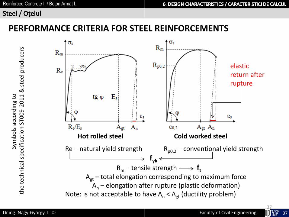
PERFORMANCE CRITERIA FOR STEEL REINFORCEMENTS
37
Hot rolled steel Cold worked steel
Sym
bo
ls a
cco
rdin
g to
th
e te
chn
ical
sp
ecif
icat
ion
ST0
09
-20
11
& s
teel
pro
du
cers
Re – natural yield strength Rp0,2 – conventional yield strength
fyk
Rm – tensile strength ft
Agt – total elongation corresponding to maximum forceAn – elongation after rupture (plastic deformation)
Note: is not acceptable to have An < Agt (ductility problem)
elastic return after rupture

Faculty of Civil EngineeringDr.ing. Nagy-György T. 38
Reinforced Concrete I. / Beton Armat I.
PERFORMANCE CRITERIA FOR STEEL REINFORCEMENTS
Ductility criteria:
- characteristic value of 𝑘 = (𝑓𝑡/𝑓𝑦)𝑘
- characteristic value of εuk
- resistance to bending-unbending and weldability
- rib factor (bond) 𝑓𝑅 = 𝐴𝑅/(𝜋𝑑𝑛𝑜𝑚𝑠)
where s = rib distance
AR = relative rib area
fR ≥ fRmin for high bond strength steel
fR < fRmin for plain bars
φ fRmin
5…6 0.035
6.5…12 0.040
>12 0.056

Faculty of Civil EngineeringDr.ing. Nagy-György T. 39
Reinforced Concrete I. / Beton Armat I.
PERFORMANCE CRITERIA FOR STEEL REINFORCEMENTS
Fatigue
Dynamic cycles leads to decreasing of strength
Dynamic cycles may be characterized by:
- Coefficient of asymmetry 𝜌 =𝜎𝑠𝑚𝑖𝑛
𝜎𝑠𝑚𝑎𝑥
- Amplitude (range of stress) ∆𝜎𝑠= 𝜎𝑠𝑚𝑎𝑥 − 𝜎𝑠𝑚𝑖𝑛
smin
smax
s

Faculty of Civil EngineeringDr.ing. Nagy-György T. 40
Reinforced Concrete I. / Beton Armat I.
PERFORMANCE CRITERIA FOR STEEL REINFORCEMENTS
Fatigue strength depends on:
• range of stress, whatever are smin & smax
• welds• steel quality:
- grade- manner of storage (fatigue strength of reinforcement in real elements is smaller with 40 … 70% than in laboratory testings due to local damages, e.g. corrosion, scratches, etc.)

Faculty of Civil EngineeringDr.ing. Nagy-György T. 41
Reinforced Concrete I. / Beton Armat I.
PERFORMANCE CRITERIA FOR STEEL REINFORCEMENTS
FatigueBehaviour of steel under fatigue load:
Wöhler diagram S-N curve real behaviour in codes
When Δ does not exceed a certain value, called limit amplitude or endurancelimit, the material will resist unlimited in time during the N loading / unloadingcycles.
Endurance limit
N – no. of cycles
S – Amplitude
= a max - a min

Faculty of Civil EngineeringDr.ing. Nagy-György T. 42
Reinforced Concrete I. / Beton Armat I.
PERFORMANCE CRITERIA FOR STEEL REINFORCEMENTS
Fatigue
Condition for bars & de-coiled rods:
∆𝜎𝑠,𝑚𝑎𝑥 ≤ 70 𝑀𝑃𝑎

Faculty of Civil EngineeringDr.ing. Nagy-György T. 43
Reinforced Concrete I. / Beton Armat I.
PERFORMANCE CRITERIA FOR STEEL REINFORCEMENTS
Other criteria:
- Ability to be bent
- Bond characteristics (fR)
- Sectional dimensions and tolerances
- Fatigue strength with upper limit of fyk for N ≥ 2x10⁶ cycles
- Weldability
- Shear strength (at least 0.3 A fyk)
- Weld resistance for welded fabrics and cages

Faculty of Civil EngineeringDr.ing. Nagy-György T. 44
Reinforced Concrete I. / Beton Armat I.

Faculty of Civil EngineeringDr.ing. Nagy-György T. 45
Reinforced Concrete I. / Beton Armat I.
Products used as reinforcement in Romania
low quality steel

Faculty of Civil EngineeringDr.ing. Nagy-György T. 46
Reinforced Concrete I. / Beton Armat I.
Modulus of elasticity
Es = 200000 MPa
Density = 7850 kg/m3
The reference value is characteristic strength steel for strength
fyk = fy - apparent value of the yield limit
fyk = f0,2 - conventional yield strength limit
Design strength of the steel
𝑓𝑦𝑑 =𝑓𝑦𝑘𝛾𝑠

Faculty of Civil EngineeringDr.ing. Nagy-György T. 47
Reinforced Concrete I. / Beton Armat I.
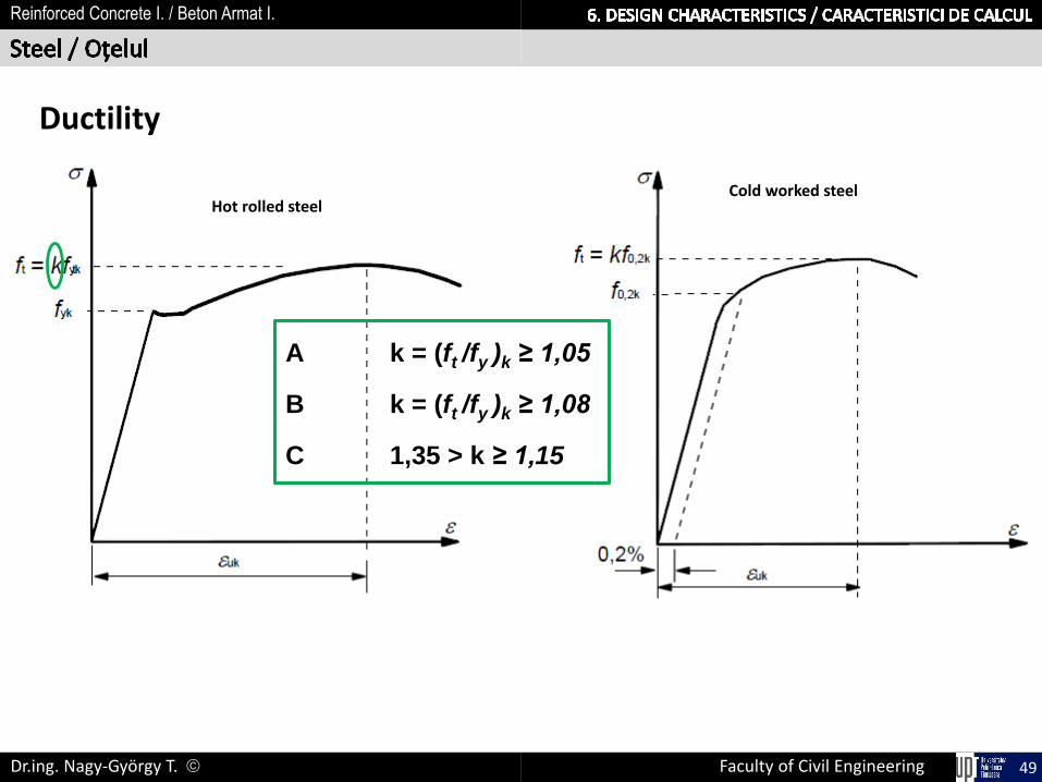
The reinforcement shall have adequate ductility as defined by the ratio of tensile strength to the yield stress, (ft/fy)k and the elongation at maximum force, εuk
Class A – generally low diameters ( 12mm), used in welded fabrics : low ductility
Class B – most commonly used in RC elements: medium ductility (DCL & DCM)
Class C – high ductility, used in earthquake resistance structures (DCH)

Faculty of Civil EngineeringDr.ing. Nagy-György T. 48
Reinforced Concrete I. / Beton Armat I.
Hot rolled steelCold worked steel
Ductility
Faculty of Civil EngineeringDr.ing. Nagy-György T. 49
Reinforced Concrete I. / Beton Armat I.
Hot rolled steelCold worked steel
A k = (ft /fy )k ≥ 1,05
B k = (ft /fy )k ≥ 1,08
C 1,35 > k ≥ 1,15
Ductility

Faculty of Civil EngineeringDr.ing. Nagy-György T. 50
Reinforced Concrete I. / Beton Armat I.
Hot rolled steelCold worked steel
Ductility
A k = (ft /fy )k ≥ 1,05
B k = (ft /fy )k ≥ 1,08
C 1,35 > k ≥ 1,15
Aεck ≥ 25‰
Bεck ≥ 50‰
Cεck ≥ 75‰

Faculty of Civil EngineeringDr.ing. Nagy-György T. 51
Reinforced Concrete I. / Beton Armat I.
DESIGN DATA FOR REINFORCING STEEL
εs
s

Faculty of Civil EngineeringDr.ing. Nagy-György T. 52
Reinforced Concrete I. / Beton Armat I.
DESIGN DATA FOR REINFORCING STEEL
s
εs
s
fyk

Faculty of Civil EngineeringDr.ing. Nagy-György T. 53
Reinforced Concrete I. / Beton Armat I.
DESIGN DATA FOR REINFORCING STEEL
εs
s
fyk
k·fyk

Faculty of Civil EngineeringDr.ing. Nagy-György T. 54
Reinforced Concrete I. / Beton Armat I.
DESIGN DATA FOR REINFORCING STEEL
εs
s
fyk
k·fyk
εuk
k·fyk

Faculty of Civil EngineeringDr.ing. Nagy-György T. 55
Reinforced Concrete I. / Beton Armat I.
DESIGN DATA FOR REINFORCING STEEL
εs
fyk
k·fyk
εuk
Es
k·fyk
s

Faculty of Civil EngineeringDr.ing. Nagy-György T. 56
Reinforced Concrete I. / Beton Armat I.
DESIGN DATA FOR REINFORCING STEEL
εs
s
fyk
k·fyk
εuk
Es
fyd= fyk/s
k·fyk
k·fyk/s

Faculty of Civil EngineeringDr.ing. Nagy-György T. 57
Reinforced Concrete I. / Beton Armat I.
DESIGN DATA FOR REINFORCING STEEL
εs
s
fyk
k·fyk
εuk
Es
fyd= fyk/s
k·fyk
k·fyk/s
fyd /Es

Faculty of Civil EngineeringDr.ing. Nagy-György T. 58
Reinforced Concrete I. / Beton Armat I.
DESIGN DATA FOR REINFORCING STEEL
εs
s
fyk
k·fyk
εuk
Es
fyd= fyk/s
k·fyk
k·fyk/s
fyd /Es

Faculty of Civil EngineeringDr.ing. Nagy-György T. 59
Reinforced Concrete I. / Beton Armat I.
DESIGN DATA FOR REINFORCING STEEL
εs
s
fyk
k·fyk
εuk
Es
fyd= fyk/s
k·fyk
k·fyk/s
fyd /Es

Faculty of Civil EngineeringDr.ing. Nagy-György T. 60
Reinforced Concrete I. / Beton Armat I.
ROMANIAN PRODUCTS
OB37 - plain bar used for stirrups and helix or as secondary reinforcement
PC52 and PC60 ribbed bars, used as principal reinforcement (structural)
Delivery:- Coiled for = 6…12 mm- Strait bars 14 mm; L = 8(10)…18 m

Faculty of Civil EngineeringDr.ing. Nagy-György T. 61
Reinforced Concrete I. / Beton Armat I.
ROMANIAN PRODUCTS
STNB cold drawn wire = 3…10mmplain wire used for welded fabrics (STAS 438/3-89)characteristics - table
- frequency of use: G-high; L-medium; S-low- style: Q – squared grid; R – rectangular grid- dimension: 6,0 x 2,45 m

Faculty of Civil EngineeringDr.ing. Nagy-György T. 62
Reinforced Concrete I. / Beton Armat I.
ROMANIAN PRODUCTS
SPPB indented wire by plastic deformation= 4…8 mmf0,2k = 460 MPaftk = 510 MPaused for welded fabrics; dimensions by the producer

Faculty of Civil EngineeringDr.ing. Nagy-György T. 63
Reinforced Concrete I. / Beton Armat I.
CLASSIFICATION OF THE ROMANIAN PRODUCTS
- Steel PC60 satisfies both criteria of strength and ductility
- Steel OB37 and PC52 don’t satisfy requirements of yielding limit strength
fy,max < 400 MPa
- Ductility is satisfied for all the laminated rebars, the ratio k= ft / fyk = 1,4…1,5
- Elongation at maximum force has higher values than those prescribed
- Delivery:- Coiled for = 6…12 mm- Strait bars 14 mm; L = 8(10)…18 m

Faculty of Civil EngineeringDr.ing. Nagy-György T. 64
Reinforced Concrete I. / Beton Armat I.
TESTS FOR BARS
Alternated bending test
mandrel
bending 90
un-bending 20
mandrel
1st bending 2nd bendingTension test
Bending-unbending test
transversal wire Testing the wire Testing the weld
mandrel
Bending test
bending 180
TESTS FOR FABRICS

Faculty of Civil EngineeringDr.ing. Nagy-György T. 65
Reinforced Concrete I. / Beton Armat I.
Dr. NAGY-GYÖRGY TamásProfessor
E-mail: [email protected]: +40 256 403 935Office: A219Web: http://www.ct.upt.ro/users/TamasNagyGyorgy/index.htm


![ìþ XéÊä ¡ê© ÖòPkc ck · à°È²á¶æÂÖ³ìþ ?±{Àæ íP|c[f / ck}?Ƹ٠¸ Æ^r|VrFX o[ tVóZPkl] ¸Ù ¸ ] ck} Î ÇÔêv?](https://img.dokumen.tips/doc/110x75/5fcdde4602f8447da504aa3e/-x-pkc-ck-pcf-ck.jpg)