Embed Size (px)
Citation preview

DPG 2001Frank Hartmann (IEKP)
P-irradiated-oxygenated Non-irradiated-oxygenatedNon-irradiated-non-oxygenatedP-irradiated-non-oxygenated sensors put in a PSI testbeam
in very short time
A „Cross-Alps“ CMS collaboration of Bari, Karlsruhe, Padova, Perugia and Wien
Silizium-Mikrostreifen-Detektoren
nach 10 Jahren LHC für CMS
Goal:• Test complete CMS like Quality assurance
• Ensure sensor functionality after 10 LHC years
DPG 2001Frank Hartmann (IEKP)
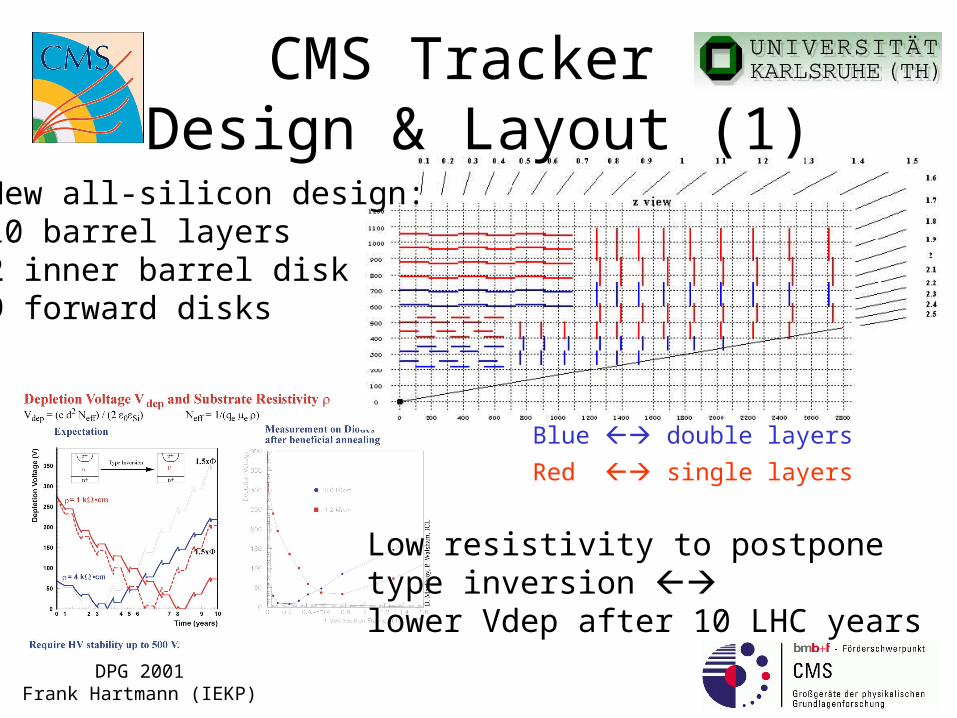
Blue double layers
Red single layers
Low resistivity to postponetype inversion lower Vdep after 10 LHC years
New all-silicon design:10 barrel layers2 inner barrel disk9 forward disks
CMS Tracker Design & Layout (1)
DPG 2001Frank Hartmann (IEKP)
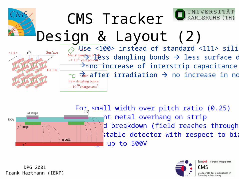
CMS Tracker Design & Layout (2)
Use <100> instead of standard <111> silicon less dangling bonds less surface damage ~no increase of interstrip capacitance after irradiation no increase in noise
For small width over pitch ratio (0.25) implement metal overhang on strip to avoid breakdown (field reaches through SiO2) more stable detector with respect to bias voltage up to 500V

DPG 2001Frank Hartmann (IEKP)
P-Irradiation at Karlsruhe
B eam d iam e te r:
2 - 1 2 m m u s in g a W o p p le r
Ir rad ia te d a re a b y p o s itio n in g :
u p to 4 0 0 * 1 0 0 m m 2
• This time: 34MeV protons. (10 LHC years)
• Sensors cooled down to –10°C during irrad. (CMS like operation)
• Future CMS QA
Karlsruhe KompaktzyklotronP ro to n en e rg ie s :1 7 - 3 5 M e V o r
1 - 1 7 M e V(u s in g a d e g ra d e r- ta rg e t)
P ro to n cu rren t: 1 0 n A - 1 0 0 m A
P ro to n flu x :
1 0 in 7 0 0 s a t 1 0 0 n A1 4 pc m 2

DPG 2001Frank Hartmann (IEKP)
165V
350V
At 21°C
Tests in the lab (1)IV CV

DPG 2001Frank Hartmann (IEKP)
101pF~Same as before
1.7M~Same as before
3.2pF (one neighbour)~Same as before
1 - 2.5nA before at 21°C
Tests in the lab (2)
~450nA

DPG 2001Frank Hartmann (IEKP)
One double-sensor module
1 module with:
2 oxygenated sensors
APV25S1
prototype hybrid
prototype repeater
In the cool-box-frame
DPG 2001Frank Hartmann (IEKP)
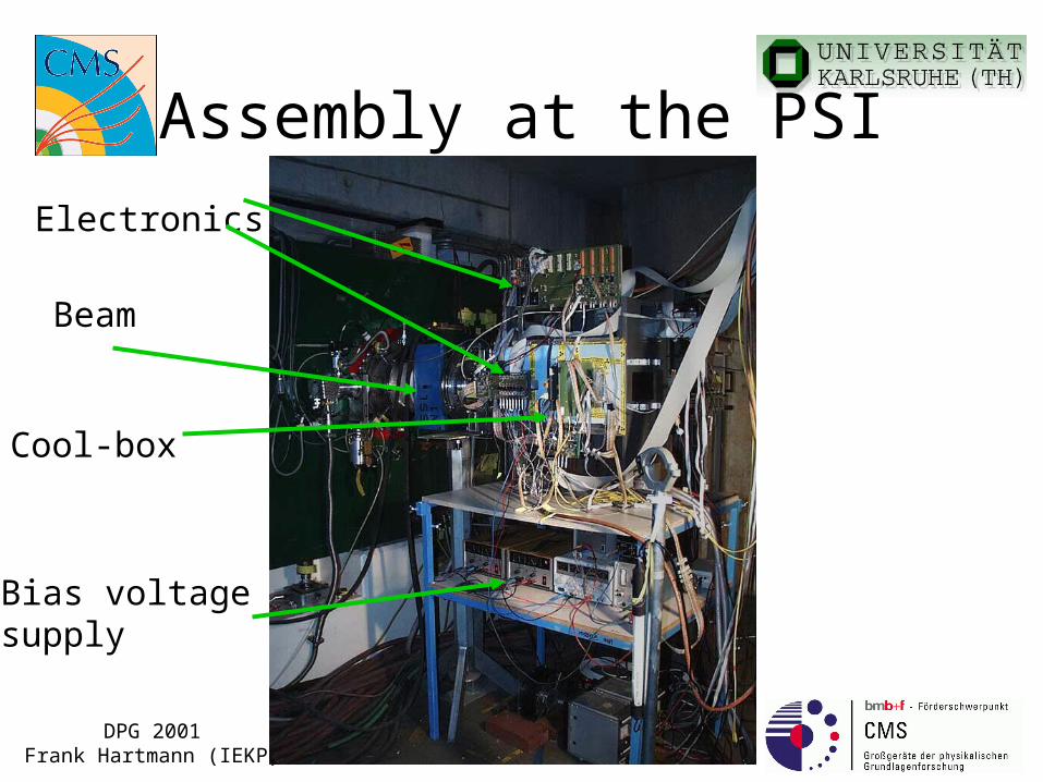
Assembly at the PSI
Beam
Bias voltage supply
Cool-box
Electronics
DPG 2001Frank Hartmann (IEKP)
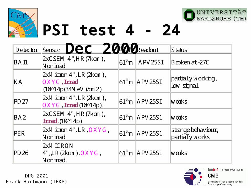
Detector Sensor Pitch Readout Status
BAI1 2xCSEM 4'', HR(7kcm), Nonirrad 61m APV25SI Broken at -27C
KA 2xMicron 4", LR(2kcm), OXYG, Irrad (10^14p(34MeV)/cm2)
61m APV25SI partially working, low signal
PD27 2xMicron 4", LR(2kcm), OXYG, Irrad(10^14p). 61m APV25SI works
BA2 2xCSEM 4", HR(7kcm), Irrad.(10^14p) 61m APV25S1 works
PER 2xMicron 4", LR, OXYG, Nonirrad 61m APV25S1
strange behaviour, partially works
PD26 2xMICRON 4",,LR(2kcm), OXYG, Nonirrad.
61m APV25S1 works
PSI test 4 - 24 Dec 2000
DPG 2001Frank Hartmann (IEKP)
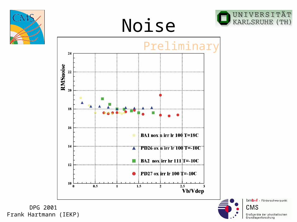
NoisePreliminary

DPG 2001Frank Hartmann (IEKP)
Signal / NoisePreliminary
DPG 2001Frank Hartmann (IEKP)
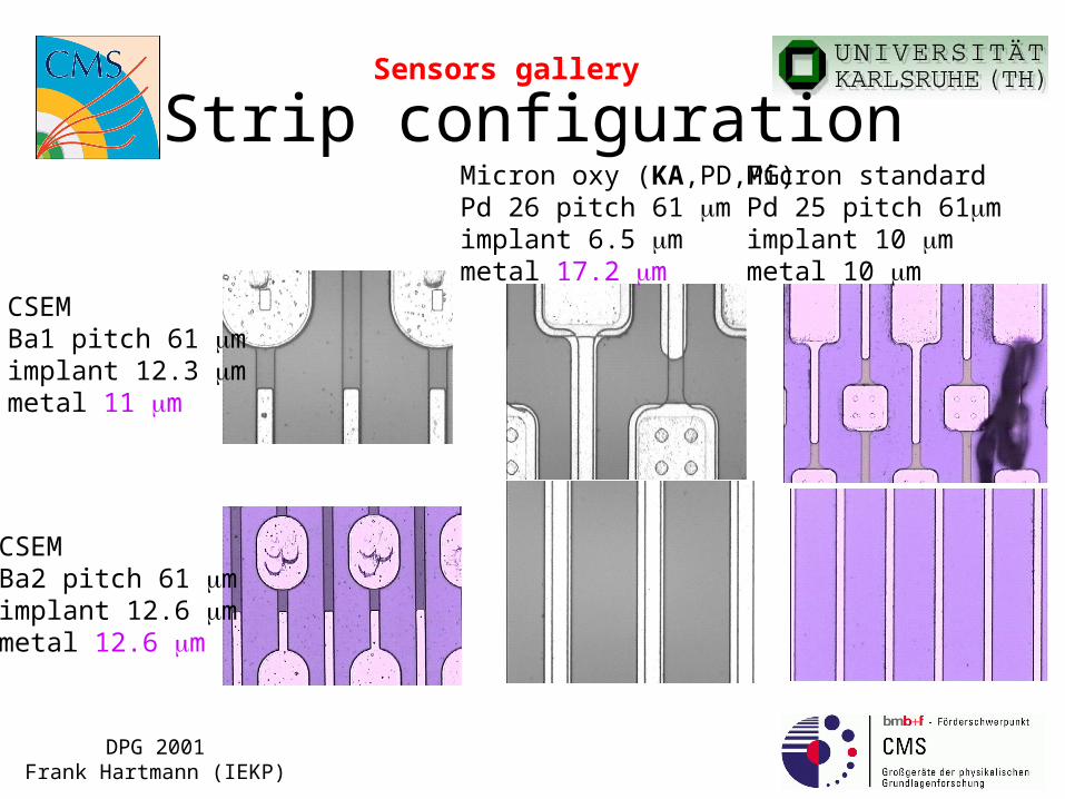
Strip configurationSensors gallery
CSEM Ba1 pitch 61 mimplant 12.3 mmetal 11 m
Micron oxy (KA,PD,PG)Pd 26 pitch 61 mimplant 6.5 mmetal 17.2 m
Micron standard Pd 25 pitch 61mimplant 10 mmetal 10 m
CSEM Ba2 pitch 61 mimplant 12.6 mmetal 12.6 m
DPG 2001Frank Hartmann (IEKP)
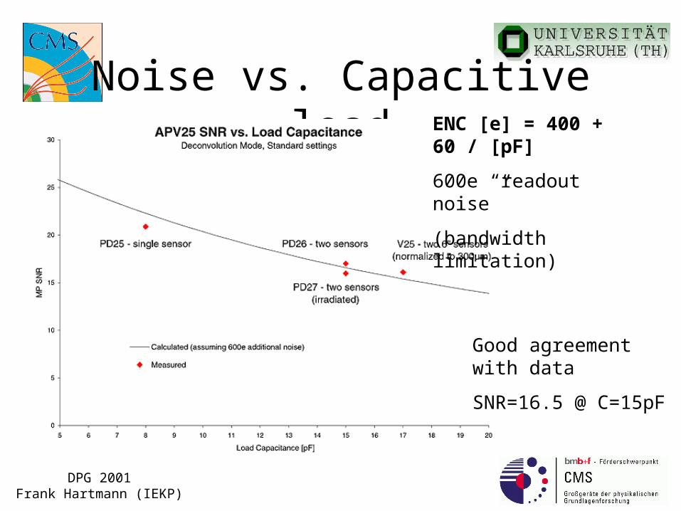
Noise vs. Capacitive loadENC [e] = 400 + 60 / [pF]
600e “readout noise”
(bandwidth limitation)
Good agreement with data
SNR=16.5 @ C=15pF

DPG 2001Frank Hartmann (IEKP)
Conclusion
• S/N of 17-18 with final readout chip and 16 for a full irradiated module looks very promising.
• S/N differences are more related to CC and Cint values depending on strip width rather than from ox or nox.
• Sensor parameters like breakdown voltages, leakage currents and strip parameters after irradiation are well within CMS specification.
CMS specifies sensor behavior (parameters) after irradiation and not the oxygen content!!!

DPG 2001Frank Hartmann (IEKP)
DPG 2001Frank Hartmann (IEKP)
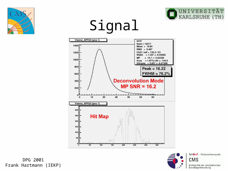
Signal
DPG 2001Frank Hartmann (IEKP)
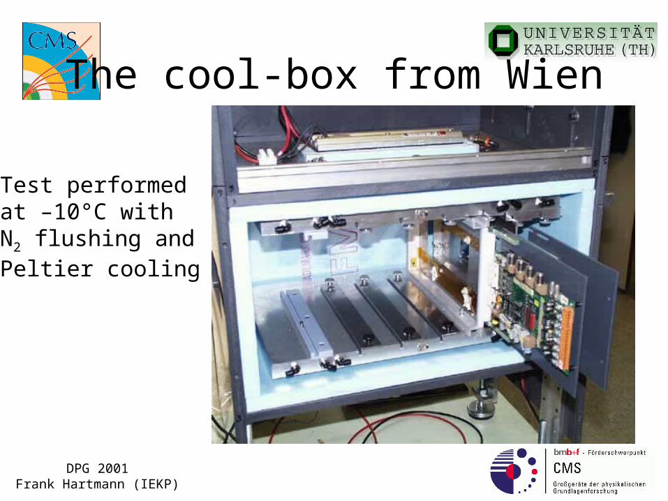
The cool-box from Wien
Test performed at –10°C with N2 flushing andPeltier cooling

DPG 2001Frank Hartmann (IEKP)
The bunker& FAST professional cabeling
DPG 2001Frank Hartmann (IEKP)
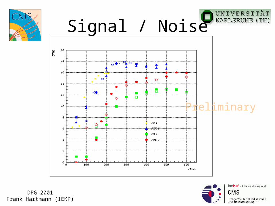
Signal / Noise
Preliminary
DPG 2001Frank Hartmann (IEKP)
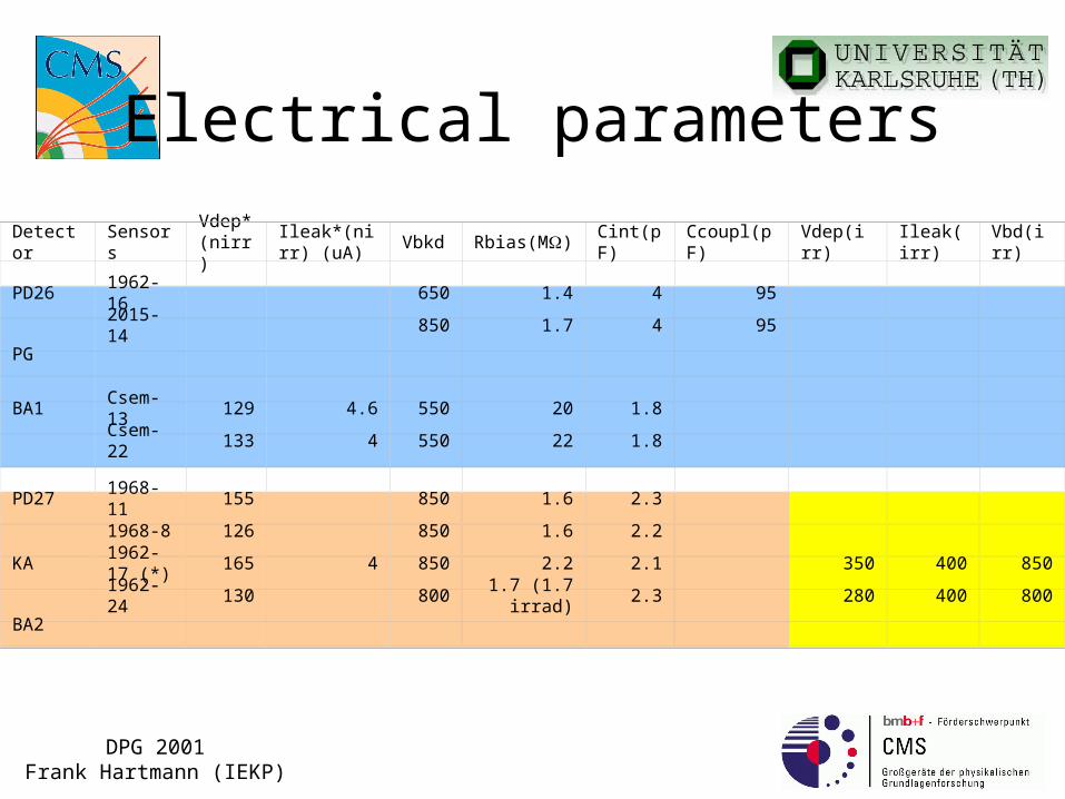
Electrical parameters
Detector SensorsVdep*(nirr)
Ileak*(nirr) (uA)
Vbkd Rbias(M) Cint(pF) Ccoupl(pF) Vdep(irr) Ileak(irr) Vbd(irr)
PD26 1962-16 650 1.4 4 95
2015-14 850 1.7 4 95
PG
BA1 Csem-13 129 4.6 550 20 1.8
Csem-22 133 4 550 22 1.8
PD27 1968-11 155 850 1.6 2.3
1968-8 126 850 1.6 2.2
KA1962-17 (*)
165 4 850 2.2 2.1 350 400 850
1962-24 130 800 1.7 (1.7 irrad) 2.3 280 400 800
BA2