Embed Size (px)
Citation preview

DP OPERATIONS GUIDANCE
Marine Technology Society Dynamic Positioning Committee – DP Operations Guidance Part 2 Appendix 3 Logistics Vessels Ver 2.0 July 31 2012
Page 1 of 70
DP Operations Guidance
Prepared through the Dynamic Positioning Committee of the
Marine Technology Society
to aid in the safe and effective management of
DP Operations
July 2012
Part 2
APPENDIX 3 (DP Logistics Vessels)

DP OPERATIONS GUIDANCE
Marine Technology Society Dynamic Positioning Committee – DP Operations Guidance Part 2 Appendix 3 Logistics Vessels Ver 2.0 July 31 2012
Page 2 of 70
TABLE OF REVISIONS
Section Page
no ORIGINAL TEXT CHANGED TEXT REMARKS
3.1 3 Safest Mode Aligned with CAM and TAM.
3.2 5
Added: In some instances Logistics Vessels are being used as platforms to execute construction type function. Where such use is contemplated, the Capability Plots may need to be regenerated to reflect the requirements of the Industrial Mission
3.2 4 SMO Changed to CAM/TAM.
4.1 10 Introduced IMO MSC 645 as base document.
4.1 10
NOTE 1 - The vessel’s DP system should normally be set up and operated to deliver the intent of the DP class notation. However, on occasion and after a proper assessment of the risks, the vessel may be set up in accordance with the requirements of the Task Appropriate Mode.
NOTE 1 - The vessel’s DP system should be set up and operated in the identified Critical Activity Mode (CAM) configuration. However, on occasion and after a proper assessment of the risks, the vessel may be set up in accordance with the identified. Task Appropriate Mode. (TAM)
To align with TAM and CAM
4.1 10
Added note 2 – The suggested default mode for Logistics vessels, performing its stated industrial mission ( provide logistics support) is to be set up and operated in CAM when within the 500m zone of fixed or floating structures/facilities.
4.1 10
A detailed risk analysis will be required if the vessel is to operate in a task appropriate mode (TAM) that provides less redundancy than that provided by the vessel’s DP equipment class notation. The detailed risk analysis should consider the consequences of loss of position relevant to the activity.
Guidance Notes A detailed risk analysis will be required if the vessel is to operate in a task appropriate mode (TAM).The detailed risk analysis should consider the consequences of loss of position relevant to the activity. Logistics vessels are not expected to operate in TAM when executing its industrial mission within the 500 m zone of a fixed or floating facility
To align with TAM and CAM
4.2 10 Inserted text on FMEA and proving trials covering both CAM and TAM

DP OPERATIONS GUIDANCE
Marine Technology Society Dynamic Positioning Committee – DP Operations Guidance Part 2 Appendix 3 Logistics Vessels Ver 2.0 July 31 2012
Page 3 of 70
Section Page
no ORIGINAL TEXT CHANGED TEXT REMARKS
4.2 Guidance
Note 13
CATEGORIZATION of FMEA FINDINGS (Difference with design philosophy document.)
Category A The failure effects exceed the worst case failure design intent or some aspect of the design is non-compliant with the ….Insert Classification Society… rules for notation …Insert DP Notation… Improvement is recommended. Category B The failure effects equal the worst case failure design intent. The design complies with the ….Insert Classification Society… rules for notation Insert DP notation… but should be reviewed to determine whether a cost effective improvement can be made. Category C Observations, comments and suggestions associated with DP safety and reliability, which …Insert Owner… may consider
Aligned with Design document
4.2 13 SMO CAM/TAM
4.2 14 To be repeated every five years
To be carried out at intervals not exceeding five years
Aligned with IMO MSC 645
4.2 14 These tests should be designed to prove full compliance with the redundancy concept.
New text
4.2 15 Insert MTS DP Vessel Design Philosophy Guidelines Parts 1 and 2 in list of references.
4.4 20
General: reworded section about Inertial navigation in combination with acoustic and Satellite DP reference systems
4.4 21
General: Inserted a section about reflectors for laser based systems should be prism Recommended for Logistics vessel to have redundant relative reference systems
4.4 22
Note 11 – The practice of connecting survey and DP is not recommended. Where it is unavoidable, isolation
Note 11 – The practice of connecting survey and DP is not recommended. Where it is unavoidable, galvanic isolation
Added galvanic
4.4 22
Added: the temptation to use the taut wire system as a winch for alternate purposes should be avoided and discouraged
Field observation on improper practices

DP OPERATIONS GUIDANCE
Marine Technology Society Dynamic Positioning Committee – DP Operations Guidance Part 2 Appendix 3 Logistics Vessels Ver 2.0 July 31 2012
Page 4 of 70
Section Page
no ORIGINAL TEXT CHANGED TEXT REMARKS
4.6 26
ECR Checklists: A series of checks and tests that verify that the vessel’s set up and configuration of systems and equipment meet the requirements of the necessary mode of operation as determined by the Safest Mode of Operation (SMO) and the DP Class or the Task Appropriate Mode (TAM).
ECR Checklists: A series of checks and tests that verify that the vessel’s set up and configuration of systems and equipment meet the requirements of Critical Activity Mode ( CAM) or Task Appropriate Mode ( TAM).
Align with TAM and CAM
4.6 27
The remainder of this subsection on Annual DP Trials is on hold pending formal publication of IMCA guidance on Annual DP Trials which is under development at the time of preparing this MTS document. Guidance will be provided in a subsequent revision of this MTS document.
Deleted as guidance has now been published (IMCA M190)
4.7 30 SMO CAMO/TAMO
4.7 30
General: Station keeping should be identified as a safety critical element and introduced the guidance for each vessel to have a ‘drive-off drift-off’ strategy
4.8 SMO and TAM Rewrite of section providing clarity on CAM and TAM. Introduced Positioning Standby
4.8 32 & 33 Introduced: ‘Positioning Standby’ including guidance
4.8 34 Described guidance for the operational mode of a logistics vessel (CAM / TAM)
4.8 37 Degraded Changed to actionable
4.8 37 ASOG Outline response Deleted
4.10 39
Inserted: Making DP critical equipment unavailable with the 500 m zone in order to carry out preventative maintenance should be avoided
DP OPERATIONS GUIDANCE
Marine Technology Society Dynamic Positioning Committee – DP Operations Guidance Part 2 Appendix 3 Logistics Vessels Ver 2.0 July 31 2012
Page 5 of 70
Section Page
no ORIGINAL TEXT CHANGED TEXT REMARKS
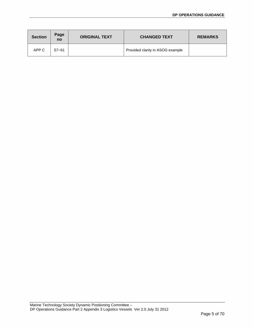
APP C 57~61 Provided clarity in ASOG example

DP OPERATIONS GUIDANCE
Marine Technology Society Dynamic Positioning Committee – DP Operations Guidance Part 2 Appendix 3 Logistics Vessels Ver 2.0 July 31 2012
Page 6 of 70
TABLE OF CONTENTS
2. INTRODUCTION ......................................................................................................... 7
2.1 Scope ............................................................................................................................ 7 2.2 Lay Out ......................................................................................................................... 7
3. DP OPERATIONAL DOCUMENTATION ................................................................... 8
3.1 General ......................................................................................................................... 8 3.2 Recommended Documentation .................................................................................... 8
4. THEMES ................................................................................................................... 14
4.1 DP Class ..................................................................................................................... 14 4.2 DP FMEA .................................................................................................................... 15 4.3 DP Capability Plots ..................................................................................................... 18 4.4 DP Footprint Plots ...................................................................................................... 20 4.5 Position Reference Systems and Sensors ................................................................. 21 4.6 Recommended DP Control Modes for DP Activities .................................................. 28 4.7 Trials and Checklists .................................................................................................. 31 4.8 DP Operations Manuals ............................................................................................. 34 4.9 Activity Operational Planning ..................................................................................... 37 4.10 Communications ......................................................................................................... 42 4.11 DP Planned Maintenance ........................................................................................... 43 4.12 DP Incidents ............................................................................................................... 44 4.13 Reporting and Record Keeping .................................................................................. 46 4.14 Competence ............................................................................................................... 47 4.15 Manning ...................................................................................................................... 49
5. INTERVENTION – ROLE OF THE DPO AND ENGINEER ...................................... 51
APPENDIX A DP FOOTPRINT PLOTS – WORKED EXAMPLES ................................ 55 APPENDIX B ANNUAL DP TRIALS TEST TABLE BLANK – DP LOGISTICS VESSELS58 APPENDIX C EXAMPLE OF CAMO AND ASOG ......................................................... 60

DP OPERATIONS GUIDANCE
Marine Technology Society Dynamic Positioning Committee – DP Operations Guidance Part 2 Appendix 3 Logistics Vessels Ver 2.0 July 31 2012
Page 7 of 70
2. INTRODUCTION
2.1 Scope
Part 2 provides operational guidance on the themes identified in Part 1.
The themes that have been identified and addressed in this document are:
1. DP Class
2. FMEA/ FMECA
3. DP Capability
4. Position Reference Systems And Sensors
5. Required Modes
6. Trials And Checklists
7. Operation Manuals
8. Activity and Operational Planning
9. Communications
10. DP Planned Maintenance
11. DP Incidents
12. Reporting And Record Keeping
13. Competency
14. Manning
15. Operator Intervention – DPOs and Engineers (Part 2 only)
Note Item 15 has been added to the fourteen identified themes and is addressed separately in subsection 5.
2.2 Lay Out
This document consists of two parts. Part 1 contains guidance on the management of DP. Part 2 contains DP operational guidance. Part 2 consists of three Appendices.
o Part 2 Appendix 1 - DP MODUs
o Part 2 Appendix 2 – DP Project/Construction Vessels
o Part 2 Appendix 3 – DP Logistics Vessels
This has been done to facilitate ease of use by these groups taking into account the uniqueness of their particular activity.
Whilst station keeping using DP is the common mode for all three groups the activity that they are undertaking may need varying emphasis on different themes.
This Part 2 contains both the content of Part 1 as well as Part 2. Part 1 content is in regular Arial font size 11, whereas Part 2 content of is in Arial italics font size 10. This clearly identifies the Part 2 content at the same time as putting it into context with Part 1 without having to refer back to a separate Part 1 document.
This is Part 2 Appendix 3 and is applicable for DP Logistics Vessels.

DP OPERATIONS GUIDANCE
Marine Technology Society Dynamic Positioning Committee – DP Operations Guidance Part 2 Appendix 3 Logistics Vessels Ver 2.0 July 31 2012
Page 8 of 70
3. DP OPERATIONAL DOCUMENTATION
3.1 General
It is recommended that DP vessel owners/operators should maintain the documentation listed in the table below and should develop and implement associated processes for the purposes of:
o ensuring the safe and effective management of the vessel in DP
o ensuring the technical suitability of the vessel for each DP activity it is required to carry out
o determining the configuration for the mode of operation ( Critical Activity Mode (CAM) and task appropriate mode (TAM)
o understanding the vessel’s station keeping capabilities following the worst case failure
o ensuring compliance with appropriate standards and guidelines
o providing training and familiarization material to vessel crews
3.2 Recommended Documentation
Table A Recommended Documentation
Current versions of the documents in the list below should be kept on board and, in addition, where feasible, at the shore based centers of technical management. Documents that have been superseded should be clearly marked and kept separate from current versions. Documents may be in electronic or, hard copy format or, both.
Further guidance relating to the documents listed below is given in appropriate sections later in this document.

DP OPERATIONS GUIDANCE
Marine Technology Society Dynamic Positioning Committee – DP Operations Guidance Part 2 Appendix 1 (MODUs) Ver 2.0 April 30 2012
Page 9 of 70
No. Document Management Guidance Operational Guidance
1 DP System FMEA or FMECA
To be kept up to date, incorporating all modifications and additions since original study, if not in the document itself, then by other traceable means. All records to be kept on board.
Modifications and additions should be covered by a MOC process that triggers updating the FMEA.
2 DP FMEA Proving Trials
To be conducted to prove initial DP FMEA and at other times to prove modifications and additions to the DP system. Tests to prove full compliance with the redundancy concept should be carried out at intervals not exceeding five years. Findings and recommendations to be addressed in accordance with their criticality. All records to be kept on board.
Modifications and additions that should be proven by testing include all those that have direct effect or, potential to affect the performance or redundancy of the DP system. This will include protective, detection and monitoring functions.
3 Annual DP Trials
To be conducted annually. Findings and recommendations to be addressed in accordance with their criticality. Previous trials reports and associated close out documentation to be kept on board.
The tests in the Annual DP Trials should be designed to prove system redundancy, as defined in the DP FMEA, system and equipment performance and functionality, to validate repairs and preventive maintenance, to test the operation of protection and detection devices and their response so as to demonstrate that the vessel’s DP system remains fit for purpose.
4 DP Capability Plots
Hard copy DP Capability Plots relevant to the vessel’s areas of operations to be readily accessible to DPOs at the DP control location.
Capability plots to be validated/ recalculated, as required, to ensure that they are suitable for the environmental conditions where the DP operations are to take place, in particular in respect of current speeds. This requirement to validate/ recalculate applies also in cases where DP vessel performance is affected by operational constraints imposed by the activity. In some instances Logistics Vessels are being used as platforms to execute construction type function. Where such use is contemplated, the Capability Plots may need to be regenerated to reflect the requirements of the Industrial Mission,
DP OPERATIONS GUIDANCE
Marine Technology Society Dynamic Positioning Committee – DP Operations Guidance Part 2 Appendix 3 Logistics Vessels Ver 2.0 July 31 2012
Page 10 of 70
No. Document Management Guidance Operational Guidance
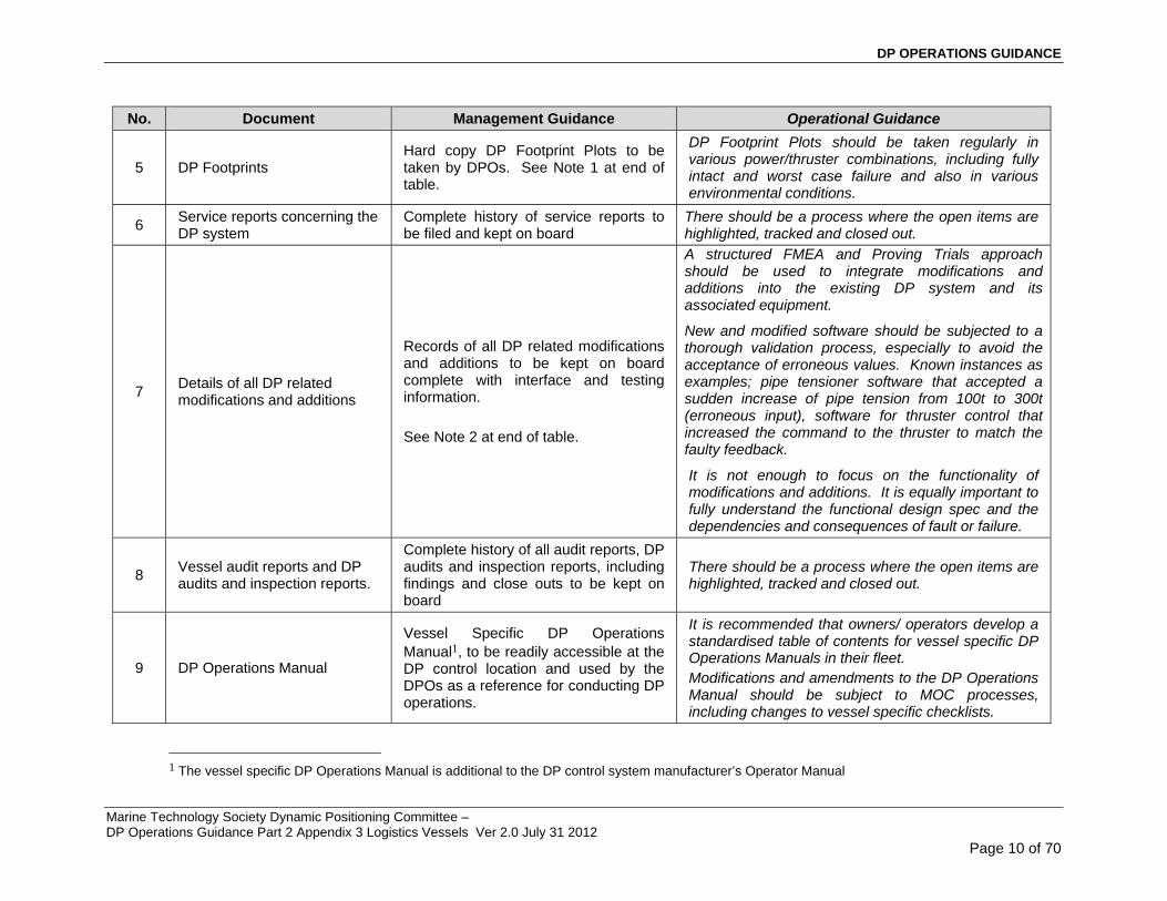
5 DP Footprints Hard copy DP Footprint Plots to be taken by DPOs. See Note 1 at end of table.
DP Footprint Plots should be taken regularly in various power/thruster combinations, including fully intact and worst case failure and also in various environmental conditions.
6 Service reports concerning the DP system
Complete history of service reports to be filed and kept on board
There should be a process where the open items are highlighted, tracked and closed out.
7 Details of all DP related modifications and additions
Records of all DP related modifications and additions to be kept on board complete with interface and testing information. See Note 2 at end of table.
A structured FMEA and Proving Trials approach should be used to integrate modifications and additions into the existing DP system and its associated equipment.
New and modified software should be subjected to a thorough validation process, especially to avoid the acceptance of erroneous values. Known instances as examples; pipe tensioner software that accepted a sudden increase of pipe tension from 100t to 300t (erroneous input), software for thruster control that increased the command to the thruster to match the faulty feedback.
It is not enough to focus on the functionality of modifications and additions. It is equally important to fully understand the functional design spec and the dependencies and consequences of fault or failure.
8 Vessel audit reports and DP audits and inspection reports.
Complete history of all audit reports, DP audits and inspection reports, including findings and close outs to be kept on board
There should be a process where the open items are highlighted, tracked and closed out.
9 DP Operations Manual
Vessel Specific DP Operations Manual1, to be readily accessible at the DP control location and used by the DPOs as a reference for conducting DP operations.
It is recommended that owners/ operators develop a standardised table of contents for vessel specific DP Operations Manuals in their fleet. Modifications and amendments to the DP Operations Manual should be subject to MOC processes, including changes to vessel specific checklists.
1 The vessel specific DP Operations Manual is additional to the DP control system manufacturer’s Operator Manual

DP OPERATIONS GUIDANCE
Marine Technology Society Dynamic Positioning Committee – DP Operations Guidance Part 2 Appendix 3 Logistics Vessels Ver 2.0 July 31 2012
Page 11 of 70
No. Document Management Guidance Operational Guidance
10 DP Incident Reports
Records of all DP station keeping and other DP related incidents to be kept on board, including investigation records and close outs.
All DP incidents should be investigated to an extent that reflects the potential consequences of the incident.
11 DP Mobilization/ DP Field Arrival/ Trials Procedures (Bridge and Engine Room)
Records of DP Mobilization Trials and DP Field Arrival Checklists to be kept on board for the period set by the owner/ operator and, where relating to a DP incident permanently stored in retrievable archives.
DP Trials and Checklists should be vessel specific and be developed from detailed information contained in the DP FMEA. They should confirm vessel performance, particularly following worst case failure, and that the vessel’s DP system is set up properly and provides the required level of redundancy.
12 DP Location and Watchkeeping checklists (Bridge and Engine Room)
Records of all DP Location and Watchkeeping Checklists to be kept on board for the period set by the owner/ operator and, where relating to a DP incident, permanently stored in retrievable archives.
As above
13 DP related drills and emergency response drills
Records of DP related drills and emergency response drills to be kept on board in retrievable archives.
DP drills can be developed from fault and single point failure scenarios addressed in the vessel’s DP FMEA. The drills should also cover extreme events that are outside the scope of the DP FMEA. The outcomes from these drills should be used in the development of DP emergency response procedures and used as training material for DP personnel. These records may be used in a cycle of continuous improvement.
14 DP fault log Records of all faults related to the DP system to be kept on board permanently in retrievable archives.
DP faults should be recorded as soon as possible after they are discovered and action/ investigation taken appropriate to the potential consequences of the fault on the vessel’s station keeping ability.

DP OPERATIONS GUIDANCE
Marine Technology Society Dynamic Positioning Committee – DP Operations Guidance Part 2 Appendix 3 Logistics Vessels Ver 2.0 July 31 2012
Page 12 of 70
No. Document Management Guidance Operational Guidance
15 DP Data Logging
Where the vessel has DP data logging facilities electronic records should be kept on board for the period set by the owner/ operator and, where relating to a DP incident, permanently stored in retrievable archives.
DP data loggers perform an important function in helping to determine root causes of faults or failures.
It is recommended that a DP data logging function is included as part of the DP system design spec.
DP data loggers should be commissioned and operational before DP system Customer Acceptance Trials (CAT) are carried out.
The DP data logger should be incorporated in the CAMO/TAM and running at all times when in DP. If not, this should trigger an Advisory condition, i.e. BLUE.
There should be specific procedures for the operation and analysis of output from the DP data logger. This should include clear instructions on how and where the records are kept. Retention of data logging data should not be limited by time. Note:- It is acknowledged that DP data loggers are not the norm on Logistics vessels. Owners are encouraged to consider the benefits to be derived by installing DP data loggers on their vessels.
16 DP alarm printer readouts
Hard copy records of the DP alarm printer readout to be kept on board for the period set by the owner/ operator and, where relating to a DP incident, permanently stored in retrievable archives.
Owners/ operators frequently require DP alarm printer readouts to be kept for the duration indicated in their Management Systems. Where this is not specified owners are encouraged to specify retention time. Alarm printouts relating to a DP incident or contractual dispute are to be permanently stored in retrievable archives.

DP OPERATIONS GUIDANCE
Marine Technology Society Dynamic Positioning Committee – DP Operations Guidance Part 2 Appendix 3 Logistics Vessels Ver 2.0 July 31 2012
Page 13 of 70
No. Document Management Guidance Operational Guidance
17 DP familiarisation and competency records
All records relating to vessel specific DP familiarisation and competency for DPOs, engineers and electricians to be kept on board permanently in retrievable archives.
Owners/operators should implement an in-house DP competency assurance process for key DP personnel which is structured, systematic and progressive. It should be noted that DPO certification is only one element in the competency assurance process. Owners/operators are recommended to make use of facilities and training programmes available to the DP sector, such as the Powersim program for advanced DPO training of power plant fault conditions, where DPOs are given detailed instruction and training in identifying and responding to power system faults. Examples include DPO intervention averting an underfrequency induced blackout on closed bus system by the DPO taking control of thrusters and biasing to increase load.
18 Résumés and vessel specific work records of all key DP personnel
Résumés of all key DP personnel, copies of certification and qualifications, records of DP watchkeeping hours to be maintained on board. Original DPO certificates and DP Log Books to be held by the DPOs onboard the vessel.
Note 1 It is acknowledged that DP Footprint Plots may be less relevant for DP MODUs than for other DP vessel types. Note 2 Owners/ operators should keep adequate records and documentation relating to modifications and additions that
could have an effect on the DP system, especially interfaces between equipment from different vendors. This is as relevant for equipment whose primary function lies outside the DP system, such as an Emergency Shutdown Systems (ESD), pipe tensioner systems and fire monitor systems as it is for DP equipment, such as propulsion, position references and sensors. All modifications and additions should be subjected to FMEA type analysis and undergo Proving Trials type testing.

DP OPERATIONS GUIDANCE
Marine Technology Society Dynamic Positioning Committee – DP Operations Guidance Part 2 Appendix 1 (MODUs) Ver 2.0 April 30 2012
Page 14 of 70
4. THEMES
4.1 DP Class
IMO MSC 645 “Guidelines for Vessels with Dynamic Positioning Systems is the base or foundation document for DP vessels.
It is recommended that DP vessels with the following DP equipment class notations be used for the following activities.
Application on DP
Minimum Recommended DP Equipment Class
(See Note 1 below)
Remarks
Drilling 2
Diving 2
Pipelay 2
Umbilical Lay 2
Lifting 2
Accommodation 2
Shuttle Offtake 2
ROV Support (Open Water)
1
ROV Support (Close Proximity - Surface/
Subsea) 2
Floating Production 2
Seismic and Survey vessels (Open water- outside 500 m zone)
** Class in accordance with contractual requirements
Well Stim 2*
Vessels of lesser Class may be used with the appropriate structured risk identification and mitigation measures in place.
Logistics Operations 2*
Vessels of lesser Class may be used with the appropriate structured risk identification and mitigation measures in place.
NOTE 1 - The vessel’s DP system should be set up and operated in the identified Critical Activity Mode (CAM) configuration. However, on occasion and after a proper assessment of the risks, the vessel may be set up in accordance with the identified Task Appropriate Mode. (TAM)
NOTE 2 – The suggested default mode for Logistics vessels, performing its stated industrial mission ( provide logistics support) is to be set up and operated in CAM when within the 500m zone of fixed or floating structures/facilities.
Guidance Notes

DP OPERATIONS GUIDANCE
Marine Technology Society Dynamic Positioning Committee – DP Operations Guidance Part 2 Appendix 3 Logistics Vessels Ver 2.0 July 31 2012
Page 15 of 70
A detailed risk analysis will be required if the vessel is to operate in a task appropriate mode (TAM).The detailed risk analysis should consider the consequences of loss of position relevant to the activity.
Logistics Vessels are not expected to operate in TAM when, executing its industrial mission within the 500 m zone of fixed or floating facilities
4.2 DP FMEA
The DP vessel’s DP FMEA is the most important technical document in the list of required documents. The requirement for a DP FMEA has its origins in IMO MSC/Circ 645 (1994) “Guidelines for Vessels with Dynamic Positioning Systems”. These benchmarking guidelines provide the foundation for all subsequent DP rules, regulations and guidance issued by Class and other industry bodies, such as IMCA.
The IMO Guidelines require all DP vessels to be subjected to survey and testing in accordance with IMO’s specified guidelines. This includes initial and periodic complete survey and testing of all systems and components required to keep position after single failures associated with the vessel’s assigned DP equipment class.
The periodic component in the IMO Guidelines requires the complete survey and testing to be repeated carried out at intervals not exceeding five years to ensure full compliance with applicable parts of the guidelines. These tests should be designed to prove full compliance with the redundancy concept. Each classification society has its own rules for five yearly testing.
In addition compliance with IMO Guidelines requires survey and testing after defects are discovered and corrected and, after a DP related accident and, whenever significant repairs or alterations are carried out, so as to demonstrate full compliance with applicable parts of the guidelines.
The IMO Guidelines do not make clear distinction between vessels of different DP equipment class.
This IMO requirement has been interpreted by the DP community such that the survey requirement is met by a DP FMEA (or FMECA2) and the testing requirement by DP FMEA Proving Trials.
Accordingly, all DP vessels of DP Class 2 or 3 are required to have a Class approved and stamped DP FMEA and DP FMEA Proving Trials.
The vessel’s DP FMEA and Proving trials should cover both CAM and TAM configurations. (This may involve the FMEA covering both open and closed bus tie configurations)
Definitions: An FMEA is a systematic analysis of systems and sub-systems to a level of detail that identifies all potential failure modes down to the appropriate sub-system level and their consequences. A FMECA is an extension of an FMEA that adds a risk assessment of each failure mode to determine its criticality.
2 Unless expressly stated in this Guidance document a FMECA is interchangeable with an FMEA.

DP OPERATIONS GUIDANCE
Marine Technology Society Dynamic Positioning Committee – DP Operations Guidance Part 2 Appendix 3 Logistics Vessels Ver 2.0 July 31 2012
Page 16 of 70
In addition to complying with the IMO Guidelines and the relevant DP rules of the vessel’s Classification Society the DP FMEA should achieve the standards of detail and analysis contained in the following industry guidance;
o IMCA M166 “Guidance on Failure Modes and Effects Analysis” o IMCA M178 “FMEA Management Guide” o IMCA M04/04 2004 “Methods of Establishing the Safety and Reliability of DP
Systems” o MTS DP Vessel Design Philosophy Guidelines Parts 1 and 2 Note FMEAs are a requirement to obtain DP Class 2 and 3 notation. Whilst
not stipulated as a class requirement for DP 1 vessels owners/ operators are encouraged to subject their DP 1 vessels to the DP FMEA process.
Note Particular attention should be paid in the DP FMEA to the interfaces between the DP system and other systems that have the potential to affect the DP system, such as where the vessel is fitted with an Emergency Shut Down (ESD) system, pipe tensioner system or fire monitor system.
Key DP personnel, including the vessel Master, DPOs, Engineers and Electricians should have a detailed knowledge of the DP FMEA and should use the information provided to be fully informed about the capabilities and limitations of the vessel’s DP system.
The results from a DP FMEA, in particular issues related to the vessel’s worst case failure and significant single point failures, should be used in the formulation of operational, emergency response and planning decisions.
Guidance Notes
These Guidance Notes on DP FMEAs are intentionally brief. They give a concise overview of the underpinning philosophy, analytical processes and the technical content of a DP FMEA. Relevant IMCA guidance, referred to in this section, should be consulted to gain a more detailed understanding.
A DP FMEA should encompass the following:-
o identify worst case failure design intent (WCFDI) and worse case failure (WCF),
o identify the equipment or subsystem, modes of operation and the equipment,
o Identify all potential failure modes and their causes,
o identify the significant single point failures,
o identify potential hidden failures,
o identify potential configuration errors,
o evaluate the effects on the system of each failure mode,
o Identify measures for eliminating or reducing the risks associated with each failure mode,
o identify trials and testing necessary to prove the conclusions,
o be updated after any major modifications and proving trials have been conducted,
o be subject to review and update as necessary, once every five years. The review should take account of new equipment and hardware/ software updates, new developments in analysis and new knowledge acquired in the intervening period,
o take account of action items from DP FMEA Proving Trials, Annual DP Trials, audits and incidents which have been or, are in the process of being, closed out,

DP OPERATIONS GUIDANCE
Marine Technology Society Dynamic Positioning Committee – DP Operations Guidance Part 2 Appendix 3 Logistics Vessels Ver 2.0 July 31 2012
Page 17 of 70
o take account of non DP systems/ auxiliary/ external systems that have interfaces with, and potential impact on DP and station keeping. These systems should be subjected to the FMEA and Proving Trials approach for software, hardware and interfaces thus ensuring the integrity of the DP system and proper integration with DP,
o take account of common mode failures that are otherwise liable to be overlooked, such as the effects of hydrocarbon gas on engine control and safety systems, which can cause diesel engines to accelerate out of control resulting in catastrophic mechanical failure and potential for black out,
o be presented as a narrative analysis of DP related systems and subsystems covering the above points (i.e. redundancy concept, hidden failures, configuration errors, etc.) and be supported by sketches and drawings,
o for DP Class 3 vessels, should consider the effects of fire and flood, not only from a compartment analysis perspective but also, where significant, at the subsystem level, e.g. the effects of fire and flood on ESD control lines and push buttons.
Note Where the redundancy concept relies on inter-switching mechanisms, the reliability and effectiveness of these mechanisms should be proven and fully documented in the DP FMEA.
Note The DP FMEA should contain an analysis of the DP control system I/Os to verify that it is consistent with the redundancy concept and should be proved at DP FMEA Proving Trials.
Note The DP FMEA should address the ESD function (if applicable), in particular the various issues relating to the status of post activation battery power supplies (UPS). Appropriate guidance is given in section 6.6 of IMCA M196, “Guidance on the Design, Selection, Installation and Use of UPS onboard Vessels”.
Note The findings from a DP FMEA and Proving Trials should be categorised into A, B or C. Categories should be clearly defined. Appropriate definitions are as follows;
Category A The failure effects exceed the worst case failure design intent or some aspect of the design is non-compliant with the ….Insert Classification Society… rules for notation …Insert DP Notation… Improvement is recommended.
Category B The failure effects equal the worst case failure design intent. The design complies with the ….Insert Classification Society… rules for notation Insert DP notation… but should be reviewed to determine whether a cost effective improvement can be made.
Category C Observations, comments and suggestions associated with DP safety and reliability, which …Insert Owner… may consider
A FMECA is an extension of an FMEA that adds a risk assessment of each failure mode to determine its criticality. Criticality is derived from an assessment of the probability that a particular failure will occur combined with the severity of the failure if it does occur.
A DP FMECA should encompass all of the listed points in DP FMEA above and, in addition, include the following steps;
o determine the severity of each failure mode,
o determine the probability of occurrence of each failure mode (using qualitative or reliable MTBF data),
o determine and rank the criticality of the identified failure modes from highest to lowest,

DP OPERATIONS GUIDANCE
Marine Technology Society Dynamic Positioning Committee – DP Operations Guidance Part 2 Appendix 3 Logistics Vessels Ver 2.0 July 31 2012
Page 18 of 70
o determine a strategy for dealing with the ranked criticalities so that remedial measures are directed appropriately in accordance with the criticality ranking.
The Criticality Analysis should be presented in tabulated form making use of risk matrices that comply with recognised international standards such as those given in IMCA M166 or IEC 60812.
Note The closing out of action items should be well documented and auditable.
The following IMCA Guidelines address the above considerations in various levels of detail; M166, M178, M04/04 and Annex.
A DP FMEA should be referred to at the following times;
o conducting task based DP operational risk assessments, where key personnel involved should have detailed knowledge of the DP FMEA,
o determining the DP vessel’s Mode of Operation ( CAM/TAM)), e.g. where the unavailability of equipment may reduce the vessel’s DP station keeping ability,
o determining the DP vessel’s Activity Specific Operating Guidelines (ASOG), e.g. where equipment performance approaches or exceeds predetermined limits,
o determining the vessel’s Task Appropriate Mode, when applicable and warranted by the specific DP operations,
o developing planned maintenance schedules, taking account of the impact of taking systems or equipment out of service,
o developing the vessel’s DP Operations and Emergency Response manuals and procedures,
o developing DP trials programs and checklists, ensuring that the single point failures identified in the DP FMEA are covered in the trials and checklists.
Note to Owners In the case of newbuilds, if DP FMEAs are within the shipyard’s scope of supply, owners are recommended to ensure that there are contractually binding agreements for the FMEA to meet specifications set out in IMCA Guidelines, M166. M178, M04/04 and Annex and preferably be carried out by an independent third party DP FMEA practitioner.
Cautionary Note DP FMEAs that are solely focused on attaining class notation and class approval may not always meet guidance standards stipulated in those IMCA Guidelines.
4.3 DP Capability Plots
DP Capability Plots should be calculated for the vessel. Guidance is provided on DP Capability Plots in IMCA M140 Rev 1, “Specification for DP Capability Plots”.
These theoretical plots are calculated from detailed information of the vessel’s hull and superstructure form and available thruster power. The calculations should use environmental data (seastate, wind and current) appropriate to the area in which the DP vessel is to operate.
These plots should show the limiting wind speed 360 degree envelopes for the scenarios below, where each point on the envelope represents the wind speed at which it is calculated that the vessel will be unable to maintain position in DP.
DP Capability Plots should include the following scenarios at current speeds of 0kts, 1kt and 2kts, or at other current speeds that are representative of the location in which the DP vessel is to operate:

DP OPERATIONS GUIDANCE
Marine Technology Society Dynamic Positioning Committee – DP Operations Guidance Part 2 Appendix 3 Logistics Vessels Ver 2.0 July 31 2012
Page 19 of 70
o Fully intact power generation and thrusters.
o Loss of most effective thruster(s).
o Following the worst case failure.
Note The DP Capability Plots should be provided in a format that is intuitive to the user on board (e.g. Polar Plot).
Guidance Notes
DP Capability Plots that do not cover Worst Case Failure are incomplete. DP Capability Plots that do not take into account thruster interaction, (thruster-thruster, thruster-hull), thruster degradation and thruster barred zones are incomplete.
Owners/ operators should note that it is important to provide a detailed scope of work to whoever is to generate the DP Capability Plots for the vessel. Experience has shown that those who generate the DP Capability Plots, such as the DP system manufacturers, may not include the Worst Case Failure, unless specifically instructed to do so. This is particularly relevant where the DP Capability Plots are included in the shipyard’s scope of supply for newbuilds.
DP Capability Plots may have to be recalculated from time to time during the lifetime of a DP vessel. For example, the installation of new equipment, such as a crane or an accommodation module on deck will alter the vessel’s outline, which, in turn, will alter the wind effect on the vessel. In these circumstances the DP Capability Plots should be re-calculated to take account of the changes.
DP Capability Plots may also have to be recalculated for thruster configurations where, due to unforeseen faults or failures or, due to essential maintenance requirements, one or more thrusters are no longer available. Where not already covered by existing calculations the revised DP Capability Plots should cover the following cases for the new thruster condition, i.e. the new fully intact condition, the new loss of most effective thruster(s) and the new worst case failure condition.
DP Capability Plots should be readily available to the DPOs at the DP control console.
DPOs should consult DP Capability Plots as a matter of course whilst the vessel is conducting DP operations.
DPOs should be fully familiar with the limits given in the DP Capability Plots for the fully intact thruster configuration, for loss of most effective thruster and for worst case failure.
DPOs should be careful when estimating the current force acting on the vessel and relating it to the DP Capability Plots. DPOs should be aware that the current force generated by the DP control system is the residual external force acting on the vessel that cannot be measured. When wind speeds are low the attendant vessel, if available, could be used to estimate current by going into drift mode.
DP Capability Plots should be used by DPOs and other key DP personnel as a reference in the planning phases when determining the vessel’s environmental operational limits for the ASOG. Where the DP Capability Plots show an undue level of heading limitations this may restrict the vessel’s operating range. This is not uncommon on vessels, such as DP tankers, that have good fore and aft thrust capability but limited thwartship capability.
It should be remembered that DP Capability Plots are theoretical calculations and that, wherever possible, opportunities should be taken to validate the DP Capability Plots by taking DP Footprint Plots. See below.

DP OPERATIONS GUIDANCE
Marine Technology Society Dynamic Positioning Committee – DP Operations Guidance Part 2 Appendix 3 Logistics Vessels Ver 2.0 July 31 2012
Page 20 of 70
4.4 DP Footprint Plots
DP Footprint Plots should also be produced on board. DP Footprint Plots are not theoretical. They are actual measurements of the vessel’s DP station keeping performance in the actual environmental conditions and thruster configuration at the time the plot was taken. DP Footprint Plots should be taken whenever opportunities arise, such as during standby periods, weather downtime or on arrival at the field. Plots should be taken for the thruster configurations used in the DP Capability Plots, i.e. fully intact, loss of most effective thruster(s) and after worst case failure.
Some DP systems have a software application that produces DP Footprint Plots electronically. DPOs can also produce DP Footprint Plots by manual methods using a plotting sheet.
DP Footprint Plots serve two main purposes.
o They provide a scatter plot of vessel positions at regular intervals around the required set position (this shows accuracy of station keeping)
o They also provide comparison points on the limiting wind speed envelope given in the theoretical DP Capability Plots (this shows wind speeds at which it was seen that the vessel was unable to maintain position, thus validating or contradicting the theoretical DP Capability Plots for the various thruster configurations.)
DP Footprint Plots serve other purposes, including learning and familiarisation opportunities for DPOs and in providing snapshots of vessel station keeping behaviour for specific locations and activities.
Theoretical DP Capability Plots and DP Footprint Plots combine together to enhance knowledge and understanding of the vessel’s DP station keeping ability.
Note DP Footprint Plots originated in harsh weather regions, such as in the North Sea. The plots are used to gain a better understanding of the vessel’s actual station keeping performance and limitations in intact and, in various degraded thruster configurations, including worst case failure, whilst the vessel is being subjected to real environmental forces.
It is acknowledged that DP Footprint Plots may be of less relevance to DP MODUs.
Guidance Notes
Manual DP Footprint Plots are generated in the following manner.
1. Use a proforma plotting sheet, comprising a 360 degree polar plotting diagram, vessel outline with thrusters indicated and space for vessel specific position reference systems and environmental data. Refer to plotting sheets in Appendix A.
2. The vessel should be in auto DP. Record wind, waves and current on the plotting sheet, drawing appropriate vectors.
3. Record thruster configuration on the plotting sheet.
4. Record the rate of turn and speed of moves. It is suggested that the following values are applied, 10deg/min and 0.3m/sec, respectively, to prevent misleading results.
5. Observe position excursions from the intended position by the most appropriate means, plotting the vessel’s position regularly, e.g. every 30 seconds.

DP OPERATIONS GUIDANCE
Marine Technology Society Dynamic Positioning Committee – DP Operations Guidance Part 2 Appendix 3 Logistics Vessels Ver 2.0 July 31 2012
Page 21 of 70
Appendix A contains two worked examples. Both worked examples are for the same DP semi-submersible drilling rig* and in the same environmental conditions. Wind was 45 to 50kts from 225 degrees with a corresponding wave height of 6m. Current was 1 coincident with wind at 1kt
Example 1 shows a DP Footprint Plot for the rig’s fully intact condition with all eight thrusters operational. The plot shows that the vessel was able to maintain position within +/- 2 meters with the wind and sea on the port quarter.
Example 2 shows a DP Footprint Plot for the rig’s worst case failure condition with four thrusters operational. The plot shows that the rig was unable to maintain position with the wind and sea on the port quarter.
Example 2 - The known circumstances at the time of taking the DP Footprint Plot, of wind, wave height and thruster configuration, in which the rig failed to maintain position, can be compared against the environmental envelope plotted on the theoretical DP Capability Plot for worst case failure. They should be similar in that the DP Capability Plot should also show that the vessel will be unable to maintain position in conditions where a 45 to 50kt wind is on the port quarter. If there is a significant difference between the two, particularly if the DP Capability Plot shows that the vessel can maintain position in the given condition, it may then be necessary to pull in the limiting wind envelope on the DP Capability Plot to the upper wind speed determined by the DP Footprint Plot for these conditions.
Cautionary Note The DP Footprint Plot positions will contain systematic position reference errors.
4.5 Position Reference Systems and Sensors
The DP vessel should be equipped with suitable position reference and sensors in accordance with the vessel’s DP class notation and operational requirements. Position reference systems should be selected with due consideration to operational requirements, both with regard to restrictions caused by the manner of deployment and expected performance in working situations.
Position reference systems comprise absolute and relative systems. An absolute system gives vessel geographical position. A relative system gives vessel position in relation to a non-fixed reference. A relative system can be used as an absolute system if installed on a point that is a fixed geographical position. And, an acoustic absolute system can be used as a relative system if attached to a non-fixed asset.
The following are the most common position reference systems in use.
Absolute DGNSS (DGPS and GLONASS)
Acoustic (USBL, SBL, LBL)
Taut wire
See Note
Relative Artemis
Laser (Fanbeam, Cyscan)
Radar (RADius, RadaScan)
DARPS
Note Class rules give minimum requirements for the number of position references. Where operational uptime is one of the key success factors the benefit gained by consciously exceeding the minimum requirements are to be evaluated. Other benefits of exceeding minimum requirements include greater redundancy and improved station keeping performance.

DP OPERATIONS GUIDANCE
Marine Technology Society Dynamic Positioning Committee – DP Operations Guidance Part 2 Appendix 3 Logistics Vessels Ver 2.0 July 31 2012
Page 22 of 70
Caution Additional position reference systems should be based on different principles. It is generally not recommended to use multiple (>2) satellite based systems in conjunction with other position reference systems as this may result in skewed weighting in favor of multiple satellite systems.
Note It could be debated that Taut Wire and Acoustic Position reference systems are relative position reference systems. For purposes of this document, absolute indicates that this position reference sensor is independent of another fixed or floating offshore structure.
Guidance Notes
Operational guidance on position reference systems and sensors is given in the table below.

DP OPERATIONS GUIDANCE
Marine Technology Society Dynamic Positioning Committee – DP Operations Guidance Part 2 Appendix 3 Logistics Vessels Ver 2.0 July 31 2012
Page 23 of 70
Recommended Absolute Position Reference Systems Recommended Relative Position References Systems if in close proximity to an offshore structure Sensors
Application on DP GPS
DGNSS (DGPS +
GLONASS) (See Note 2 below)
SBL (See
Note 1 below)
USBL/ SSBL (See
Note 1 below)
LBL (See
Note 1 below)
Taut Wire (See Note
12 below)
Min Number
(See Note 3 below)
Artemis Laser Radar Gangway DARPS
Min Fixed
platform (See
Notes 4 5 & 6
below*)
TLP/SPAR/etc. < min
movement (See Notes 4, 5 & 6 below*)
TLP/SPAR/etc. > min
movement (See Notes 4, 5 & 6 below*)
Gyros, VRUs and
Wind Sensors
(See Note 7 below)
Drilling
If in deep open water
Redundant - one dual frequency
<700m <700m >700m <350m 3 Y Y Y N N 3 mixed abs & rel
3 mixed abs & rel 3 relative only 3
Diving N Y <700m <700m >700m <350m 3 Y Y Y N N 3 mixed abs & rel
3 mixed abs & rel 3 relative only 3
Pipelay N Y N N N N 3 Y Y Y N N 3 mixed abs & rel
3 mixed abs & rel 3 relative only 3
Umbilical Lay N Y N N N N 3 Y Y Y N N 3 mixed abs & rel
3 mixed abs & rel 3 relative only 3
Riser Pull in N Y <700m <700m >700m <350m 3 Y Y Y N N
3 mixed abs & rel
3 mixed abs & rel 3 relative only 3
Lifting N Y <700m <700m >700m <350m 3 Y Y Y N N 3 mixed abs & rel
3 mixed abs & rel 3 relative only 3
Accommodation N Y <700m <700m >700m <350m 3 Y Y Y Y N 3 mixed abs & rel
3 mixed abs & rel 3 relative only 3
Shuttle Offtake N Y N N N N 3 Y Y Y N Y 3 mixed abs & rel
3 mixed abs & rel 3 relative only 3
ROV Support N Y <700m <700m >700m <350m 2 N N N N N * * *See Note 8 below 2

DP OPERATIONS GUIDANCE
Marine Technology Society Dynamic Positioning Committee – DP Operations Guidance Part 2 Appendix 3 Logistics Vessels Ver 2.0 July 31 2012
Page 24 of 70
Recommended Absolute Position Reference Systems Recommended Relative Position References Systems if in close proximity to an offshore structure Sensors
Application on DP GPS
DGNSS (DGPS +
GLONASS) (See Note 2 below)
SBL (See
Note 1 below)
USBL/ SSBL (See
Note 1 below)
LBL (See
Note 1 below)
Taut Wire (See Note
12 below)
Min Number
(See Note 3 below)
Artemis Laser Radar Gangway DARPS
Min Fixed
platform (See
Notes 4 5 & 6
below*)
TLP/SPAR/etc. < min
movement (See Notes 4, 5 & 6 below*)
TLP/SPAR/etc. > min
movement (See Notes 4, 5 & 6 below*)
Gyros, VRUs and
Wind Sensors
(See Note 7 below)
Floating Production Unit N Y <700m <700m >700m <350m 3 N N N N N NA NA NA 3
Well Stim
N unless open water
Y <700m <700m >700m <350m 2 Y Y Y Y Y 2 * * 2
OSV Snatch Lifts N Y <700m <700m >700m <350m 2 Y Y Y N N 1 2 mixed abs and rel 2 2
OSV HAZMAT Transfer no quick disconnect
N Y <700m <700m >700m <350m 3 Y Y Y Y N 2 3 mixed abs & rel 3 relative only 3
OSV HAZMAT Transfer with quick disconnect
N Y <700m <700m >700m <350m 2 Y Y Y Y N 2 * * 3
OSV with shaft gens and single stern thruster
N Y <700m <700m >700m <350m 2 Y Y Y Y Y 3 * * 3
Wind Turbine installation N Y NA NA NA NA 2 N N N N N NA NA NA 2
Standby Vessels Y Y <700m <700m >700m <m 1 N N N N N NA NA NA 1 or <

DP OPERATIONS GUIDANCE
Marine Technology Society Dynamic Positioning Committee – DP Operations Guidance Part 2 Appendix 3 Logistics Vessels Ver 2.0 July 31 2012
Page 25 of 70
Note 1 (Acoustics) – The acoustic LUSBL system is not included in the above table since it is a combination of USBL and LBL in one system, where the USBL is typically used to calibrate the LBL system. Standalone USBL systems are not the norm on DP drilling MODUs.
The abbreviations, USBL and SSBL, are referred to in the above table. Although the abbreviations differ they both refer to the same acoustic application although supplied by different vendors.
It is recommended that, wherever possible, multiple acoustic systems are completely separated and independent in all respects. For instance, this would require the use of separate and independent hull transceivers.
Note 2 (Inertial Aided Navigation) Owners/ operators should consider the advantages of acoustic positioning systems that have an inertial navigation System input to create an Inertial Aided Navigation (IAN) reference sensor. IAN input can be implemented in one of the redundant DGNSS systems or in one of the redundant acoustic position reference systems. This technique introduces the attributes of differentiation. Differentiation can reduce the risk of common mode failure.). IAN changes the characteristics of how the reference behaves and minimizes the probability of both (IAN and non-IAN) systems being rejected
Introduction of IAN in DGNSS and Acoustic Systems provides additional robustness to position reference systems and the means to
o overcome the update rate limitations of speed of sound in water,
o overcome the limitations on satellite based position reference systems brought upon by poor satellite geometry
o For GNSS systems this enhancement can fill the “holes” in positioning information in extraordinary and difficult conditions that otherwise might invalidate the satellite based positioning information, such as during times of scintillation and satellite ageing.
o For acoustic systems (USBL and LBL), field tests have proven that the enhancement improves the update rate to 1 hz regardless of waterdepth.
Sub Note:- It is acknowledged that Inertial Aided Navigation is not expected to be the norm on Logistics vessels. It has been included to enhance Owners/Operators awareness and for possible consideration if Logistics Vessels are being contemplated for project/construction type activities.
Note 3 (Satellite Systems) – Satellite based systems that use a combination of signals from DGPS and GLONASS satellites provide enhanced redundancy over systems that use only a single satellite source.
It is recommended that, wherever possible, multiple satellite based systems are completely separated and independent in all respects. For instance, this would require the use of different masts for the satellite antennae, separate cable routeing, different vendors and software. Where there is diversity of vendors and software it is recommended that the acceptance/ rejection logic is verified against the DP system manufacturer’s specifications. There have been incidents in the past where diversity of vendors and software has resulted in loss of position due to the acceptance of erroneous values within the software.
Care should be taken at all times when using satellite based systems close to platforms. Guidance is given in IMCA M141, “Guidelines on the Use of DGPS as a Position Reference in DP Control Systems”, which highlights potential problems when within 150m of a platform, such as the masking of GPS signals, masking of differential signals, radio interference and multipath. Good DGPS close to structures should be considered as a bonus. In these locations DGPS should not be considered as the primary position reference system.
Where multiple DGPS systems are being used, consideration should be given to set each system with a different elevation mask. This is so that any jump in position that may occur

DP OPERATIONS GUIDANCE
Marine Technology Society Dynamic Positioning Committee – DP Operations Guidance Part 2 Appendix 3 Logistics Vessels Ver 2.0 July 31 2012
Page 26 of 70
when a satellite comes into view will hit one DGPS before the next and will give the DPO some time to take action.
Note 4 (Absolute Systems) - Where three absolute systems are used it is recommended that they are based on two different principles. Only where it is impractical to use systems based on different principles should all three be of the same type. This is of particular significance where DGPS is concerned where the satellite constellation provides a source for a common mode failure.
Note 5 (DP at non fixed Assets, e.g. FPSOs/TLPs/ pars/MODUs) – When carrying out DP activities in close proximity to or in conjunction with floating facilities it is strongly recommended that redundant relative position reference systems are used. In these situations a mix of absolute and relative position reference systems for station keeping is to be used only after validating that movement of the floating structure, if any, does not impact station keeping. The DPOs must be extremely vigilant when using a mix of absolute and relative position references and must be fully aware of the potential danger of diverging positioning information from both types of system.
The minimum movement referred to in the table above refers to the actual measured movement of floating facility, e.g. FPSO/TLP/Spar. To measure this movement the DP vessel should use an absolute position reference system, such as DGPS, as the sole source for positioning information and use the relative positioning system, such as RADius, RADASCAN or Fanbeam, sited on the floating facility to measure the fluctuations in its movement.
It should also be noted that there are non-fixed offshore facilities, such as TLPs and Spars where an acoustic system, although normally considered as an absolute system, can be used as a relative system. This can be accomplished by installing the transponder/ beacon onto the submerged part of the TLP or Spar at an appropriate depth. Some TLPs and Spars are fitted with suitable subsea brackets or cradles for transponders/ beacons.
Laser Based Systems- Laser based systems should use prisms as targets. The use of the potential higher reflectivity of prisms over other reflective surfaces provides the ability to address issues experienced with tracking of spurious targets. (By enabling setting of “rejection” thresholds.). Operations manuals should contain guidance on the use of such features in laser based systems.
Sub Note:- Logistics vessels are recommended to have redundant relative position reference systems installed. Redundancy is to be achieved by systems based on different principles (Laser Based Systems (e.g., Fanbeam, Cyscan), Radar Based systems (e.g. RADius, Radascan)
Note 6 (Absolute and Relative Systems) - When using DGPS/GLONASS in a mix of absolute and relative position reference systems, in particular where there are two satellite based systems in a mix of three, users should bear in mind the possibility of the offshore structure blocking the satellite signals and the consequences for station keeping.
Note 7 – Wherever practical and feasible it is recommended that redundancy requirements are met by diversity of suppliers, e.g. satellite based position reference systems from different manufacturers and differential signals from different sources. This applies equally to sensors such as gyro compasses, VRUs and wind sensors.
Note 8 (Sensors) - Given the impact on heading/ position keeping it is recommended that vessels with an equivalent DP 2 class notation are provided with three gyro compasses, irrespective of the requirements of the applicable Classification Society DP rules. It should be noted that some Classification Societies, including ABS and DNV already require three gyro compasses for a DP class 2 notation.
Gyro compasses are normally fitted with a correction facility which inputs the vessel’s latitude and speed. The effects of incorrect latitude or, more importantly, speed could result in a significant error in output heading. It is therefore important to ensure that the latitude and

DP OPERATIONS GUIDANCE
Marine Technology Society Dynamic Positioning Committee – DP Operations Guidance Part 2 Appendix 3 Logistics Vessels Ver 2.0 July 31 2012
Page 27 of 70
speed corrections are applied. Some systems use automatic input from GPS for these corrections. This is not recommended since there are a number of system errors that can result in undesired heading changes. It is therefore recommended to use manual input of latitude and speed.
Wind sensors are known to have suffered common mode failures, such as icing in higher latitudes, lightning, heavy rain and birds. All types of wind sensor are vulnerable, including ultrasonic types. Where ultrasonic type wind sensors are fitted, the consequences for station keeping of common mode failures, that affect these ultrasonic sensors, may be prevented by fitting mechanical wind sensors.
DP vessels are frequently fitted with sensor systems, other than heading, motion and wind, which have a potential to affect the DP system and station keeping should there be an erroneous or invalid input from them. These include draft sensors and pipelay tension sensors, where an erroneous or invalid input could result in extreme values and distortion of external forces and result in large position excursion (drive off) from the desired set point position. There should be means of preventing erroneous values from being accepted by DP. An often practiced procedure which should prevent the above problems is to input these values manually and not to rely on the automatic input function, if fitted. There should also be means of ensuring that erroneous values are prevented from being input manually.
Note 9 - Where it is anticipated that due to operational requirements the DP vessel will require to be positioned in close proximity to the non-fixed facility and where the potential for shadowing of DGPS exists, then redundancy in relative position reference sensors should be considered.
Note 10 – Where, as is normal, multiple position references are in use by DP, the DPOs should monitor the weightings closely so as to ensure that no one system or set of systems is ‘hogging” the weighting. DPOs should recognise the potential dangers of using multiple satellite based systems (>2) in the suite of position reference systems and that this could result in skewed ‘weighting” in favor of satellite systems at the expense of other position references. It is recommended that no more than two satellite based position reference systems be used to provide position solution as inputs into DP.
Note 11 – New or retrofitted position references are sometimes interfaced into DP through inputs designed for other position references because the DP control system has not been designed to accept them. Examples of this are pseudo Artemis or pseudo acoustics. This practice is not recommended unless accompanied by a detailed risk analysis and the residual risk, if any, is deemed acceptable.
Note 12 – The practice of connecting survey and DP is not recommended. Where it is unavoidable, galvanic isolation between the systems is to be provided. DPOs should have ultimate control over the input. All necessary precautions should be taken to ensure that the vessel’s station keeping is not affected and should be addressed in the FMEA.
Note 13 (Taut wires) – Care should be exercised when lowering or repositioning taut wire weights that divers and ROVs are alerted and are a safe distance from the seabed position. Taut wire weights should also be placed clear of pipelines, manifolds or other subsea assets. These subsea assets should be positively identified prior to positioning taut wire weights, e.g. by the ROV. Care should also be taken that the taut wires are not fouled by other subsea lines or obstructions.
It is possible for thruster wash to interact with a taut wire, acting as a strong current and causing position instability. The thruster wash could be from own vessel or from another vessel close by. DPOs should be aware of the potential for this to occur.
DPOs should be alert to the potential for taut wire weights to “skip” along the seabed and provide inaccurate positioning information. This can be avoided by ensuring that the tension control is properly calibrated and operating within specified parameters and that the angle of

DP OPERATIONS GUIDANCE
Marine Technology Society Dynamic Positioning Committee – DP Operations Guidance Part 2 Appendix 3 Logistics Vessels Ver 2.0 July 31 2012
Page 28 of 70
wire inclination is kept as near to vertical as is possible and should not normally exceed 10 degrees.
DPOs should also be aware of the potential for taut wire systems to become a “perfect” reference. This can have different causes, including the taut wire touching the side of own vessel or, otherwise being restricted in its movement, or by a faulty gimbal sensor. Most DP systems will detect this fault. DPOs should ensure that the warning and alarm limits are properly set and operational.
The wires in use in modern taut wire systems are generally 5mm or 6mm in diameter. Weights are in the region of 400kg to 500kg. Taut wires are quite highly stressed for marine wire ropes and are liable to breakage, particularly at points of weakness, such as continuous wear at the spot on the main sheave, continuous wear at any guide blocks and kinks or damage caused by poor spooling or where the wire is attached to the weight. The potential for wire breakage is reduced by regular inspection of the taut wire system and by slipping and cutting (cropping) the taut wire on a regular basis.
Taut wire systems are known to suffer inaccuracies at water depths over 350m, especially in high current areas. This should be taken into consideration when planning DP operations.
The temptation to use the taut wire system as a lifting device for alternate purposes is to be avoided and discouraged.
Note 14 – It is important that software, parameters and values used by position reference systems are compatible with the software and acceptance criteria used by the DP control system and that this is verified by analysis and testing.
Attention is drawn to IMO MSC/Circ 645 where three MRU/VRUs are stipulated when vessel positioning is fully dependent on correct MRU/VRU signals.
4.6 Recommended DP Control Modes for DP Activities
The DP vessel should be equipped with suitable DP modes and features with due consideration to operational requirements, both with regard to restrictions caused by the activity and performance criteria required to execute the activity safely and successfully.
The following selected DP control modes are relevant to specific DP activities.
Target Follow Enables the DP vessel to follow a moving target and is used, for example, to follow an ROV along a pipeline.
Heavy Lift Takes account of the effects of the load transfer on the mass of the vessel and the additional lateral force, normally by reducing gain and relaxing the DP controller.
External Force Compensation
Where the measured external force acting on the vessel, which is separate from the environment, is included in the DP calculation and treated as a force feed forward. This mode is used to account for pipe tensions in a pipe layer and hawser tension in a shuttle tanker.
Fire Monitor Compensation
Used to compensate for the varying forces exerted on vessel from the fire monitors.
DP OPERATIONS GUIDANCE
Marine Technology Society Dynamic Positioning Committee – DP Operations Guidance Part 2 Appendix 3 Logistics Vessels Ver 2.0 July 31 2012
Page 29 of 70
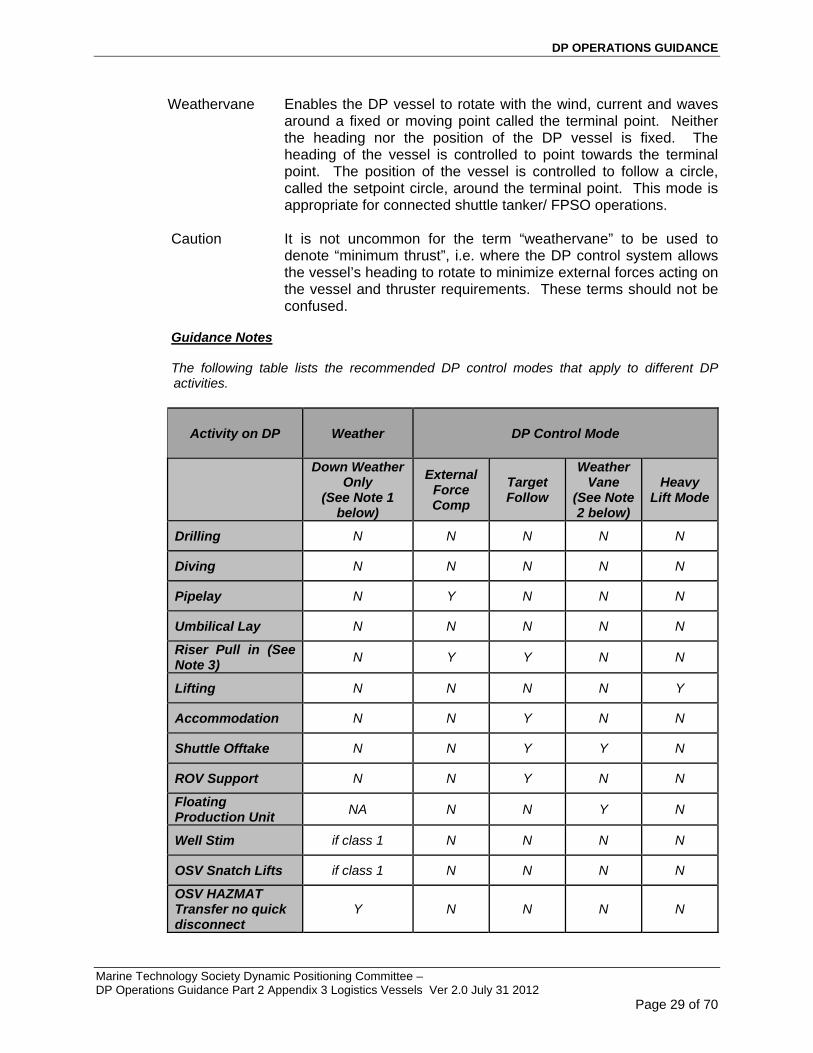
Weathervane Enables the DP vessel to rotate with the wind, current and waves around a fixed or moving point called the terminal point. Neither the heading nor the position of the DP vessel is fixed. The heading of the vessel is controlled to point towards the terminal point. The position of the vessel is controlled to follow a circle, called the setpoint circle, around the terminal point. This mode is appropriate for connected shuttle tanker/ FPSO operations.
Caution It is not uncommon for the term “weathervane” to be used to
denote “minimum thrust”, i.e. where the DP control system allows the vessel’s heading to rotate to minimize external forces acting on the vessel and thruster requirements. These terms should not be confused.
Guidance Notes The following table lists the recommended DP control modes that apply to different DP activities.
Activity on DP Weather DP Control Mode
Down Weather Only
(See Note 1 below)
External Force Comp
Target Follow
Weather Vane
(See Note 2 below)
Heavy Lift Mode
Drilling N N N N N
Diving N N N N N
Pipelay N Y N N N
Umbilical Lay N N N N N
Riser Pull in (See Note 3)
N Y Y N N
Lifting N N N N Y
Accommodation N N Y N N
Shuttle Offtake N N Y Y N
ROV Support N N Y N N
Floating Production Unit
NA N N Y N
Well Stim if class 1 N N N N
OSV Snatch Lifts if class 1 N N N N
OSV HAZMAT Transfer no quick disconnect
Y N N N N

DP OPERATIONS GUIDANCE
Marine Technology Society Dynamic Positioning Committee – DP Operations Guidance Part 2 Appendix 3 Logistics Vessels Ver 2.0 July 31 2012
Page 30 of 70
Activity on DP Weather DP Control Mode
Down Weather Only
(See Note 1 below)
External Force Comp
Target Follow
Weather Vane
(See Note 2 below)
Heavy Lift Mode
OSV HAZMAT Transfer with quick disconnect
N N N N N
OSV with shaft gens and single stern thruster
Needs to head into weather
N N N N
Standby Vessels Y if class 1 N N N N
Note 1 The term “down weather” means that the vessel is on that side of the offshore structure where the environmental forces, acting on their own, would move the vessel away from the structure. An alternative term is that the vessel is on the “force off” side of the structure.
Note 2 The term “weathervane” has a specific meaning in the DP shuttle tanker industry.
Note 3 Heavy lift type issues have been experienced on vessels provided with A frames which have been used in installation type activities. (e.g. - A frame when used off a logistics type vessel on DP where stiffness “created” during set down operations resulted in instability causing buckling of A Frame.) The potential for such instability should be assessed if A Frame is being contemplated for use while vessel is on DP. Note 4 The vessel specific DP Operations Manual should contain sufficient detail of these operating modes and features.
Note 5 The DPOs are to familiarize themselves with operational constraints/ requirements of these modes and features.
Note 6 A detailed and documented risk assessment should be carried out when it is planned to perform any of the above activities without the recommended DP control mode.
Note 7 Where DP vessels, such as DP MODUs carrying out subsea construction activities, are engaged in activities outside their normal scope they should do so using the recommended DP control mode. This may mean that the mode has to be installed in the DP control system.

DP OPERATIONS GUIDANCE
Marine Technology Society Dynamic Positioning Committee – DP Operations Guidance Part 2 Appendix 3 Logistics Vessels Ver 2.0 July 31 2012
Page 31 of 70
4.7 Trials and Checklists
A range of trials and checklists is to be provided for each DP vessel and implemented as a verification that the vessel’s DP system complies with and, is operated in accordance with, applicable standards and guidelines. This verification process should confirm the failure modes and their effects on the systems and equipment analysed in the DP FMEA document (to include the Worst Case Failure) and the vessel’s station keeping ability following its Worst Case Failure. Owners/ operators should refer to the following list of trials and checklists when developing an appropriate regime for their own DP vessels. The list below is a typical list for a DP dive support vessel.
DP FMEA Proving Trials: A series of tests used to prove expected effects of failure modes found in the FMEA desktop analysis. These tests should also include the testing of interfaces between different vendor systems and equipment. These tests should be conducted immediately following launching of a new build vessel and following modifications, additions, and upgrades repairs.
Endurance Trials:- (new build/ system modifications class requirement): To prove the operation of the DP system under load conditions for at least 4 hours without significant alarms of the DP system.
Annual DP Trials:- A series of tests of fault and failure conditions relevant to the DP System. The tests should be designed to prove system redundancy, as defined in the DP FMEA, system performance and equipment functionality, to validate repairs and preventive maintenance, and test the operation of protection and detection devices and responses so as to demonstrate that the vessel’s DP system remains fit for purpose. Annual DP Trials should be performed at a specific occasion once a year and within 3 months of the anniversary of the previous year’s trials. Annual DP Trials also provide the opportunities for training of the vessel’s crew and enhancement of their knowledge of failure modes and their effects.
Note Experience has shown that, owing to heavy operational demands, DP drilling units are not usually able to meet the above criteria for conducting Annual DP Trials at a specific time once a year. This has been recognized by the industry with publication of specific guidance relating to the conduct of Annual DP Trials for DP MODUs. This is given in IMCA M191, “Guidelines for Annual DP Trials for DP Mobile Offshore Drilling Units”. The guidance sets out a regime of annual testing that is conducted on an incremental basis throughout the year as opportunities arise but needs to be completed within a twelve month period.
DP Mobilization Trials: A series of tests to be carried out at the start of a contract, subject to client requirements, to demonstrate redundancy and functional limitations of the DP system.
DP Field Arrival Trials: A series of checks and tests that confirm satisfactory performance of the DP system and verify the set up mode of operation and DP functions.
DP Location Set Up Checklist: A series of checks to demonstrate that the vessel is properly set up for the location, in particular the satisfactory performance of the position reference systems.

DP OPERATIONS GUIDANCE
Marine Technology Society Dynamic Positioning Committee – DP Operations Guidance Part 2 Appendix 3 Logistics Vessels Ver 2.0 July 31 2012
Page 32 of 70
Pre-Dive Checklist: A series of checks performed prior to commencing diving operations. Main and back up communication tests should be included in this process.
ECR Checklists: A series of checks and tests that verify that the vessel’s set up and configuration of systems and equipment meet the requirements of Critical Activity Mode ( CAM) or Task Appropriate Mode ( TAM).
500m Checks: A series of checks and tests performed before entering the 500m zone of an asset in which set up mode and functions are verified and confirmed. Approval is then obtained to operate in close proximity to the asset. Main and back up communication tests should be included in this process.
Watch Status/ 6 Hour Checklist: A series of checks and tests performed by the DPOs to verify and confirm the set up of the DP system prior to taking over the DP watch.
Post DP Incident Trials: Tests performed to ensure that the corrective/ repair measures taken following a DP incident have properly addressed the causes of the incident and that the vessel’s DP system is in a safe and operable condition.
Post DP Modification Trials: A series of checks and tests that are used to determine the effects of modifications and/ or additions on the DP system and the vessel’s subsequent station keeping performance.
Note The nomenclature used for the trials and checklists listed above is based on the guideline document, IMCA M112,:”Guidelines for Auditing Vessels with DP Systems”. It is recognized that these trials and checklists could be given other titles.
Guidance Notes
Annual DP Trials
IMCA M190 provides guidance on Developing and Conducting Annual DP Trials Programme for DP Vessels.
It is to be noted that guidance contained in M182 applies to Supply Vessels carrying out Supply Operations. Owners are encouraged to use the guidance provided in IMCA M190 to develop and conduct Annual DP trials
It is to be noted that M191, which addresses Annual DP Trials is applicable to MODU’s and not to all vessels. Text from M191 is included in this section to draw attention to the purpose of Annual DP Trials.
The following guidelines apply to the development and the conduct of Annual DP Trials for a DP MODU in accordance with guidance contained in IMCA M191. M191 guidance describes a regime of annual testing that is conducted on an incremental basis throughout the year as opportunities arise but needs to be completed within a twelve month period. M191 also recognises the contribution that planned maintenance systems can play in verifying the status and performance of certain DP equipment throughout the year.
M191 gives the purpose of Annual DP Trials as follow;
“...... to improve the DP system safety and performance by testing faults and failure conditions important to DP safety to prove the ability of the vessel to keep position after single point failures associated with the IMO equipment class and to verify the FMEA requirements. When faults identified during the year on similar DP MODUs are determined to be feasible on the vessel then additional tests should be incorporated in the trials program.”

DP OPERATIONS GUIDANCE
Marine Technology Society Dynamic Positioning Committee – DP Operations Guidance Part 2 Appendix 3 Logistics Vessels Ver 2.0 July 31 2012
Page 33 of 70
Using the above quotation as the background, owners/ operators should use the vessel specific DP FMEA and Proving Trials as the principal source for developing the Annual DP Trials program.
DP Mobilization Trials
These trials should be carried out by the vessel’s crew as part of the mobilizing program prior to the start of a new project. The tests carried out at these trials are less than are carried out at Annual DP Trials but more than at DP Field Arrival Checks. The tests should confirm the vessel’s redundancy concept and station keeping performance after worst case failure. They should also provide assurance of the integrity of the vessel’s DP system and the vessel’s operational limitations.
DP Field Arrival Checks
These checks should be carried out on arrival at the field. The purpose of these checks is to ensure satisfactory operation of the DP system and should include a full functional check of the operation of all thrusters and power generating equipment and systems, auto DP and all control modes. The checks should also ensure that the DP system is set up properly.
DP Location Set Up Checklist
These checks should confirm that the vessel is properly set up for the working location and that the performance of the position reference systems is satisfactory for that location. These checks should take account of any limitations of the position reference systems for that location. These checks should be repeated for each change of location.
ECR Checklists
These checks should be carried out by the ER staff and reported to the DPOs prior to start of operations and at fixed periods during DP operations these checks should be developed from the vessel’s DP FMEA and should confirm that the vessel’s systems and equipment are set up and configured for the appropriate operating mode. It is the responsibility of engine room watch personnel to advise the DPOs, at any time, of any abnormalities in relevant systems or equipment that may affect DP operations.
500m Checks
All vessels should undertake 500m checks. Only vessels engaged in support activities to remain within the 500m zone. The 500m zone is not to be used as a standby location unless required to support a specific activity.
Vessel heading to be tested at 500m checks to ensure that thrusters loads are acceptable( i.e. determine whether the thrusters loads are within the load limits for ASOG) It is important that the vessel carries out its checks on the same heading as at the final working location.
Depending on the performance and distance limitations of the position reference system(s) in use (e.g. Fanbeam); the vessel heading checks may have to be repeated at an intermediate step between the 500 m line and the working location at, for example, 10 m from the working location, prior to commencing work activity.
Watch Status/ 6 Hour Checklist
The purpose of these checks is to record the status of the DP system and configuration. The checks should verify that the vessel’s station keeping performance at the working location is satisfactory and, in particular, that the position reference systems are properly set up and operating satisfactorily. No testing is carried out for these checks. DPOs should complete the checklist prior to taking over the watch, not during the first few minutes of the watch.

DP OPERATIONS GUIDANCE
Marine Technology Society Dynamic Positioning Committee – DP Operations Guidance Part 2 Appendix 3 Logistics Vessels Ver 2.0 July 31 2012
Page 34 of 70
Post Modification/ Upgrade DP Trials
It is essential to ensure that any modification, change or upgrade to the DP system is fully tested and that the vessel’s redundancy concept has not been affected. Testing should follow on from a detailed FMEA type analysis of the change which should be fully documented.
The following example shows the inherent dangers of failing to take proper account of change. In this example the installation of a more up to date and faster OS computer resulted in the new computer re-booting too early and failing to “ride through” the brief power interruption that resulted from the activation of a changeover relay. This resulted in the temporary loss of that operator station.
4.8 DP Operations Manuals
A vessel specific DP Operations Manual should be prepared for each DP vessel.
The vessel specific DP Operations Manual is the most important operational document in the list of required documents. The requirement for a manual has its origins in IMO MSC/Circ 645 (1994) “Guidelines for Vessels with Dynamic Positioning Systems”.
The IMO Guidelines require a series of checklists, test procedures and DP operating instructions to be incorporated into one manual.
Each Classification Society has its own specific requirements for a DP Operations Manual, each with different requirements for content.
The recommendations set out below address areas that are not necessarily required by class. They are based on current industry practices.
The manual should contain sufficiently detailed instruction and guidance to enable the vessel to be operated safely in DP and safely execute its intended activities. This will include a clear statement on the DP philosophy for the vessel, the organisation, responsibilities and roles of key DP personnel, training and competency, watchkeeping and manning, vessel technical data and layout, vessel DP capabilities, operating limits, operating modes, the planning and preparation of DP operations, DP operating procedures, emergency procedures, DP incident handling and alert systems and vessel specific trials and checklists that apply uniquely to the vessel.
The manual should specifically address operational interfaces between different vendor systems and equipment to ensure that they are configured and operated properly. This should include interfaces between systems and equipment that are not part of the DP system but which may affect the DP system, such as Emergency Disconnect Systems (EDS) on MODUs, tensioner systems on Pipelay vessels, etc.
The vessel specific manual may also contain generic content, such as company policies, procedures and standing orders.
The manual should represent the way the vessel is operated in DP. For complicated power systems and/ or thruster configurations, it may be useful provide the operator with a thruster and generator operating strategy (TAGOS) to assist in the decision on what generators and thrusters to use for different circumstances and different equipment availabilities.

DP OPERATIONS GUIDANCE
Marine Technology Society Dynamic Positioning Committee – DP Operations Guidance Part 2 Appendix 3 Logistics Vessels Ver 2.0 July 31 2012
Page 35 of 70
Guidance on the contents of vessel specific DP Operations Manuals is provided in the following IMCA guidelines, M103, M109, M117 (contingency training) and in class society DP rules.
Guidance Notes
The provision and development of the manual is the responsibility of the DP vessel owner or manager and should be incorporated in the company’s SMS and, where relevant, developed and managed in accordance with Requirement 7 of the ISM Code, which states, as follows;
“The Company should establish procedures for the preparation of plans and instructions, including checklists as appropriate, for key shipboard operations concerning the safety of the ship and the prevention of pollution. The various tasks involved should be defined and assigned to qualified personnel.”
Development of the DP Operations manual should consider the following
Station Keeping should be identified as a Safety Critical Element.
By recognition as a Safety Critical Element, relevant focus is to be provided by
o Appropriately addressing DP equipment in Inspection Repair and Maintenance requirements
o Level of detail in procedures and Contingency Plans.
o Appropriately addressing training and specifying drills that must be carried out.
The manual should be a standalone document in hard copy. Owners/operators, at their discretion, may provide this in an electronic format
The manual should be readily accessible to all relevant DP personnel, including the master, DPOs, engineers and electricians. At least one controlled copy including any updates and, where necessary, appendices should be kept on the DP navigating bridge.
All relevant DP personnel should be given sufficient opportunity to familiarise themselves fully with the document and should be fully conversant with the sections of the manual that relate to their duties and responsibilities.
The manual should address operating issues relating to equipment and systems that are interfaced to the DP system. This will include ESD systems (if installed), where the consequences of an automatic shutdown triggered by an ESD may result in undesirable consequences. The potential for this adverse situation should be assessed and appropriate preventative measures put in place. Due consideration should be given to initiating disconnect sequence preceding an ESD resulting in a black out. Detailed procedures are to be developed for operating ESD. Procedures should highlight criteria for initiation and consequences.
Owners/operators may wish to refer to the following guidance when developing the vessel/ rig specific DP operations manual;
Section 1 Management of DP Operations (company/vessel specific)
Company/vessel standing operational policies
Basic principles of DP, functional overview of a DP control system
Vessel specific overview of DP system (vessel overview document)
Vessel specific DP philosophy, CAMO/TAMO, ASOG, open/closed bus-tie configurations, worst case failure, environmental envelopes, vessel/rig DP station keeping capabilities

DP OPERATIONS GUIDANCE
Marine Technology Society Dynamic Positioning Committee – DP Operations Guidance Part 2 Appendix 3 Logistics Vessels Ver 2.0 July 31 2012
Page 36 of 70
Vessel specific Drive off to Drift off Strategy. (Drive off to Drift off strategy- The vessel specific philosophy to attempt to address a Drive Off situation with a view to convert it to a drift off event. Detailed procedures to achieve this are to be developed and incorporated into the DP Operations Manual.
Related DP guidance and reference documents
Section 2 DP System Description and Operation (vessel/rig specific)
Power generation, distribution, electrical systems, thrusters and propulsion (thruster and generator operating strategy, TAGOS)
Power management, auxiliary systems, fire and flood
DP control system and automation, DP computers and operator stations and networks, including, operating modes
Position reference systems and sensors; DGNSS/Hydroacoustic/taut wires, gyros, VRUs, wind sensors draft sensors, current sensors, etc.
Communications systems, internal and external, routine and emergency.
If applicable, Disconnect systems; auto/ manual emergency shutdown systems (ESD), emergency disconnect system (EDS [disconnect sequence]), other emergency and alert systems, interfaces with other vendors equipment (e.g. tensioner systems, external force input). (The failure modes of these systems and the potential effects on the vessel’s station keeping ability should be addressed in the DP FMEA).
Section 3 DP Operations Procedures
Procedure for planning DP operations, including environmental criteria, use of DP capability analysis and DP footprints, DP system set up, power and propulsion set up, required levels of redundancy, position reference system planning, integration with activity planning, simultaneous operations, risk assessment.
Development of ASOG (activity specific operating guidelines), requiring input from analysis, simulation study, proven blackout recovery times and EDS times (if applicable) and determination of red and yellow watch circles. Development of activity specific criteria for normal, advisory, actionable and emergency conditions, ASOG communications and response procedures, emergency DP procedures, including drive off, drift off, force off, blowout/ shallow gas, fire and/or explosion, loss of well control, severe weather, loss of DP position references, loss of redundancy, black out, collision, squalls, etc.
Position reference system deployment, operation and recovery, including hydrophones, acoustic arrays, battery procedures, DGPS set up and differential corrections, other PRS procedures
Normal DP marine operations, including voyage, transit and field arrival checklists, Annual DP Trials, mobilization trials, field arrival checklists, location set up checklists, watchhandover checklists, Activity planning and pre-departure checklists, ESD/EDS trials (where appropriate), 500m safety zone operations, optimum position and heading, position and heading changes, standby time, data logging, offset and turn testing, ROV operations, helicopter operations, operations in strong currents, adverse and heavy weather procedures, special operations.

DP OPERATIONS GUIDANCE
Marine Technology Society Dynamic Positioning Committee – DP Operations Guidance Part 2 Appendix 3 Logistics Vessels Ver 2.0 July 31 2012
Page 37 of 70
Communications, including routine internal communications, external locations, emergency procedures, testing, alert systems, typical communications protocols and messages.
DP incident definition, investigation, reporting, close out and record keeping.
Section 4 Organisation and Responsibility
DP organisation, including onboard organisation, key DP personnel, DP technical and operational support onshore and offshore, manning levels
Duties and responsibilities of key personnel involved in DP operations, examples, master, DPOs, chief engineer, engineers, electrical officers, ETOs, construction superintendent, etc.
Onboard watch routines, watchkeeping duties, DP desk procedures, DP handover procedures, DP log keeping and documentation, including weather log, beacon log, DP standing orders, bridge and engine room, drillers shack,
DP training, familiarisation and competency assessment, including onboard programs and experience levels, skills development, emergency training, drills and exercises.
DP reporting and record keeping, including daily reporting, monthly DP status report, tests and trials reporting, DP incidents and equipment failure reports, vendor reports, DP correspondence, reporting matrix, etc.
Operator Intervention Appendix
4.9 Activity Operational Planning
In recognizing that exposure to risks manifests itself during vessel operations it is recommended that activities performed by DP vessels should be subject to planning and preparation. In planning and preparing for the activities the following should be considered and, where appropriate, documented:
o Configuration for the Critical Activity Mode of Operation (CAMO) or, where appropriate, the Task Appropriate Mode (TAM).
o Preparation of the Activity Specific Operating Guidelines (ASOG), including onboard discussion with all relevant stakeholders as part of the pre-project execution/ activity.
o Discussion to be included in pre-project execution readiness checklist.
o Capabilities of the vessel, both intact and residual capability, following Worst Case Failure (WCF).
o Limitations imposed by water depth.
o Consequences of a loss of position and/ or heading.
o Limitations imposed upon operations by residual capability.
o SIMOPS and marine vessel interaction and consequences arising from change of status (Green to Blue, Yellow or Red).
o The activity being performed and the necessary time to terminate to bring vessel to a safe position upon the onset of failure.
o Initiating “Positioning Standby”

DP OPERATIONS GUIDANCE
Marine Technology Society Dynamic Positioning Committee – DP Operations Guidance Part 2 Appendix 3 Logistics Vessels Ver 2.0 July 31 2012
Page 38 of 70
Activities should include day to day operations, any specific operation relevant to the design of the vessel, as well as any unique operations the vessel is called upon to perform.
Appropriate measures should be in place to clearly identify critical tasks/operational phases of the activity and to ensure that the vessel is set up in the agreed to Mode (CAM or TAM). Criteria for Operations undertaken as CAM should be within post WCF capability. Where a decision has been made to operate in a TAM a separate ASOG covering TAM should be produced.
Note The ASOG should be developed by extracting all the relevant information from detailed technical review of the vessel’s DP FMEA, operational manuals and project specific procedures. The ASOG should be validated on board.
On a DP MODU, ASOGs are known as WSOGs. Some owners refer to it as WSOC (Well Specific Operating Criteria).
Guidance Notes
Positioning Standby:
Positioning standby is a condition that is triggered during the execution of the Industrial Mission when warranted. Positioning standby is initiated to bring all station keeping critical elements (Equipment, People, and Processes) to a higher state of readiness, for a defined period, with the objective of preventing a loss of position b:
Ensuring that all needed equipment is available and or running where necessary
People are in position to respond to an event and prevent escalation
Positioning Standby may initiate a:
A change in configuration from TAM to CAM ( Note:- Logistics vessels are expected to be operated in CAM when within the 500 m zone of floating/fixed facilities)
Cessation of non-critical activities, including suspension of routine IRM during the period when positioning standby is in effect. ( personnel in right places)
Examples of positioning standby are:
Heavy Lift Operations
Increase in Time to Terminate (TTT)
Deteriorating weather
Station Keeping Equipment issues
Difficulties being experienced in Industrial mission
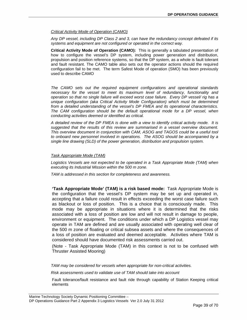
DP OPERATIONS GUIDANCE
Marine Technology Society Dynamic Positioning Committee – DP Operations Guidance Part 2 Appendix 3 Logistics Vessels Ver 2.0 July 31 2012
Page 39 of 70
Critical Activity Mode of Operation (CAMO)
Any DP vessel, including DP Class 2 and 3, can have the redundancy concept defeated if its systems and equipment are not configured or operated in the correct way.
Critical Activity Mode of Operation (CAMO): This is generally a tabulated presentation of how to configure the vessel’s DP system, including power generation and distribution, propulsion and position reference systems, so that the DP system, as a whole is fault tolerant and fault resistant. The CAMO table also sets out the operator actions should the required configuration fail to be met. The term Safest Mode of operation (SMO) has been previously used to describe CAMO
The CAMO sets out the required equipment configurations and operational standards necessary for the vessel to meet its maximum level of redundancy, functionality and operation so that no single failure will exceed worst case failure. Every DP vessel/ rig has a unique configuration (aka Critical Activity Mode Configuration) which must be determined from a detailed understanding of the vessel’s DP FMEA and its operational characteristics. The CAM configuration should be the default operational mode for a DP vessel, when conducting activities deemed or identified as critical.
A detailed review of the DP FMEA is done with a view to identify critical activity mode. It is suggested that the results of this review are summarised in a vessel overview document. This overview document in conjunction with CAM, ASOG and TAGOS could be a useful tool to onboard new personnel involved in operations. The ASOG should be accompanied by a single line drawing (SLD) of the power generation, distribution and propulsion system.
Task Appropriate Mode (TAM)
Logistics Vessels are not expected to be operated in a Task Appropriate Mode (TAM) when executing its Industrial Mission within the 500 m zone.
TAM is addressed in this section for completeness and awareness.
‘Task Appropriate Mode’ (TAM) is a risk based mode: Task Appropriate Mode is the configuration that the vessel’s DP system may be set up and operated in, accepting that a failure could result in effects exceeding the worst case failure such as blackout or loss of position. This is a choice that is consciously made. This mode may be appropriate in situations where it is determined that the risks associated with a loss of position are low and will not result in damage to people, environment or equipment. The conditions under which a DP Logistics vessel may operate in TAM are defined and are usually associated with operating well clear of the 500 m zone of floating or critical subsea assets and where the consequences of a loss of position are evaluated and deemed acceptable. Activities where TAM is considered should have documented risk assessments carried out.
(Note - Task Appropriate Mode (TAM) in this context is not to be confused with Thruster Assisted Mooring)
TAM may be considered for vessels when appropriate for non-critical activities.
Risk assessments used to validate use of TAM should take into account
Fault tolerance/fault resistance and fault ride through capability of Station Keeping critical elements

DP OPERATIONS GUIDANCE
Marine Technology Society Dynamic Positioning Committee – DP Operations Guidance Part 2 Appendix 3 Logistics Vessels Ver 2.0 July 31 2012
Page 40 of 70
The benefits of power plant stability (usually the reason why TAM is considered) vs. the potential for a complete loss of the power plant and the consequences.
(NOTE: CAMO is synonymous with CAM and TAMO is synonymous with TAM)
For diesel electric vessels the TAM may mean operating with closed bus, whereas CAM may require open bus.
Example 1: A DP MODU may operate in this mode (TAM) during times when Time to Terminate is short, and in Critical Activity Mode, when Time to Terminate is long.
Example 2: A DP pipelay vessel may operate in this mode (TAM) when well clear of the 500m zone of a surface or mission critical subsea asset, and in Critical Activity Mode (CAM) when inside 500m.
Activity Specific Operating Guidelines (ASOG)
The ASOG differs from the CAM and TAM in that it relates specifically to a known location and activity and, in the case of a DP drilling vessel/rig, to a specific well operation. The ASOG performs the same function as Well Specific Operating Guidelines (WSOG), which relate to drilling activities. The ASOG differs from the CAM and TAM in that the ASOG sets the operational, environmental and equipment performance limits for the DP vessel in relation to the specific activity that it is undertaking, whereas the CAM and TAM may not be location specific. An ASOG should be developed for every activity and location.
A central component in the ASOG is proven knowledge of black out recovery time. Reference should also be made to relevant studies/ analysis (if applicable) for an activity being undertaken (e.g. analysis related to riser transfer operations, heavy lift operations, permanent mooring connection operations)
Summary A DP vessel should always be set up in accordance with its predetermined CAM or when determined to be appropriate, in TAM. CAM is the default mode for vessel engaged in Logistics Support function. ASOG should always be developed and implemented by a DP vessel for every activity (location specific) that it carries out.
Note The vessel owns the CAM/TAM and ASOG document and the process that is used to develop it, from inception through to implementation.
Refer to Appendix C for an example of a CAMO and ASOG for a DP Logistics / Vessel.
The CAMO/TAM is presented in a tabulated format and shows two conditions (GREEN – NORMAL) and (BLUE – ADVISORY) for each item, as follows;
CRITIAL ACTIVITY MODE (CAM) OF OPERATION – OUTLINE
GREEN BLUE
Definition
Normal operations – all systems and equipment fully operational, DP verification processes completed and DP set up confirmed.
Advisory status – where any of the GREEN conditions are not met.
ResponseFor DP operations to commence and continue the conditions in the GREEN column must be met.
Conduct risk assessment to determine whether to continue, change position or cease operations.
The CAMO/TAM goes beyond equipment set up. It also defines operational standards. Typical items contained in the CAMO/TAMO will include the following;
o Power plant set up, including whether operating open or closed bus

DP OPERATIONS GUIDANCE
Marine Technology Society Dynamic Positioning Committee – DP Operations Guidance Part 2 Appendix 3 Logistics Vessels Ver 2.0 July 31 2012
Page 41 of 70
o Diesel generators, including confirmation of 100% output in DP
o Thrusters, including confirmation of 100% output in DP
o Power management, including configuration, confirmation that auto stop is off, black start enabled
o Uninterruptible power supplies (UPS), including confirmation of power supply, functional testing, no cross connections
o Manual controls and independent joystick, including confirmation of readiness and testing
o DP control system, including consequence analysis, mode availability and selection
o Position reference systems, including availability, testing and selection, absolute and relative systems, placement of targets for DP OSVs
o Set speed of rotation and speed of moves, suggest 10deg/min and 0.3m/sec, respectively
o Sensors, including availability, testing and selection
o Fuel systems, including confirm redundancy, tank levels, standby starts, isolations, crossovers
o Sea water cooling, including confirm redundancy, standby starts, isolations, crossovers
o Fresh water cooling, including confirm redundancy, standby starts, isolations, crossovers
o Compressed air, including confirm redundancy, safest compressor operating mode
o DP and ER manning, including watchkeeping rotas, qualifications and competency of watchkeepers
o Trials and checklists
o ESD status (If applicable)
The ASOG is presented in a tabulated format and shows four conditions (GREEN – NORMAL), (BLUE – ADVISORY), (YELLOW – ACTIONABLE) and (RED – EMERGENCY), as follows;
ACTIVITY SPECIFIC OPERATING GUIDELINES - OUTLINE
GREEN BLUE YELLOW RED
Defin
ition
Normal operations – all systems fully functional and operating within acceptable performance limits.
Advisory status – approaching performance limits or reportable alarm status. Operations may continue whilst risks are being assessed. A failure has occurred that does not affect DP redundancy.
Actionable status -
Pre-defined performance limits reached, component or system failure resulting in loss of redundancy.
The vessel/rig maintains position although the vessel has lost its redundancy.
Emergency status – pre-defined operational or performance limits exceeded, component or system failure resulting in loss of control or position.
An ASOG for a DP Logistics vessel will typically cover the following items;

DP OPERATIONS GUIDANCE
Marine Technology Society Dynamic Positioning Committee – DP Operations Guidance Part 2 Appendix 3 Logistics Vessels Ver 2.0 July 31 2012
Page 42 of 70
o Weather forecast and environmental conditions, including wind speed limits, current speed limits, wave height limits
o Vessel positioning performance (weather related), including position and heading excursions
o Drive off, drift off scenarios
o Diesel generators, including minimum number required for the activity, performance limits and failures (TAGOS)
o Diesel generator loads (TAGOS)
o Thrusters, minimum number required for the activity, performance limits and failures (TAGOS)
o Thruster loads (TAGOS)
o Phase back conditions (including thruster phase back, drilling phase back and DP control system power limiting)
o Battery and UPS systems
o PMS and VMS status and operation
o Auxiliary systems, including fuel, SW and FW cooling, air – performance limits and failures
o Uninterruptible power supplies (UPS), including operation, charger output and supply status, failures
o DP control system, including operation and performance of DP controllers and OS, failures
o DP control system displays, including mimics, performance and failures
o DP networks, including operation and redundancy, failures
o Position reference systems, including number of enabled systems and performance, failures
o Sensors, including number of enabled systems, performance and criticality to activity, failures
o Critical communications, including onboard systems, performance and failures
o Non-essential DP systems, including ventilation and a/c – performance and failures
o Fire, flood, visibility, collision, including threat to safety of the DP operation
o Simultaneous operations, including communications with assets
4.10 Communications
The vessel should be equipped with the appropriate primary and secondary equipment needed to communicate between all parties (stakeholders) whilst carrying out the intended task.
Effective internal and external communications is a key tool to manage risk.
Communications in this context include voice, visual (lights/displays) and audible means (alarms). Means of communication are not limited to the above but include integrated IT systems using wireless network technology that combine communications with other features, including AIS and DGNSS.

DP OPERATIONS GUIDANCE
Marine Technology Society Dynamic Positioning Committee – DP Operations Guidance Part 2 Appendix 3 Logistics Vessels Ver 2.0 July 31 2012
Page 43 of 70
Operational specific visual and voice communications should ensure that the pertinent information flows between the key operating points as well as to and from assets and/ or other vessels that might be affected by the operation being carried out.
These operating points may be onboard the vessel as well as on other facilities involved with the activity. Communication protocols are to be set up to provide pertinent information regarding intent, current status of planned as well as unexpected events during the execution of the activity.
Continuity of communications during foreseeable emergency situations should be taken into account.
Communications should be taken into account when detailing the roles and responsibilities of key personnel during the planning stages for the intended task, ensuring that a common working language and terminology is used at all times.
Guidance on communications is provided in M103, M182 and M205.
Note The importance of communication to be emphasized by incorporating into the ASOG.
Guidance Notes
There should be redundant voice communications systems to all key locations on board the DPO vessel. At least one of the systems should be hands free. The DPO should have a view or CCTV coverage of all important operational areas onboard as well as of important points of interest external to the vessel.
Communications and alarm systems should be protected against power supply failure. Battery/ UPS back up power supplies are recommended.
Some modern communications and alarm systems rely solely on software activated alarms through the network. This sole dependency is not recommended. Manual activation of alarms should never be overlooked in design or in operation.
Communications and alarm systems for all DP related equipment and systems and other equipment and systems not directly related to DP, but which will have an effect on DP, should be located close to the DP control station. This should include fire zone alarms systems.
Simultaneous operations (SIMOPS) depend on effective communications between all vessels and units involved in the operation. It is important that change of status between vessels and units engaged in SIMOPs is communicated speedily and reliably. It should be noted that developments in sensor and communications technologies are underway to relay, among other things, change of vessel or unit CAMO/TAMO or ASOG status. With these systems any change of status from GREEN to BLUE, YELLOW or RED will be instantaneously relayed to all vessels and units engaged in SIMOPs. These technologies are expected to deliver and aid in the management of complex SIMOPS.
4.11 DP Planned Maintenance
DP vessels should have a structured planned maintenance system that specifically addresses maintenance of the vessel’s DP system, equipment and support systems. Relevant guidance is given in IMCA M109.
Planned maintenance should address all equipment that has an impact on the vessel’s station keeping capabilities. This should include indirect components such as generator circuit breakers, bus tie breakers, etc. Maintenance should include regular cleaning, calibration, and testing of equipment as outlined in manufacturer’s recommendations and industry guidelines.

DP OPERATIONS GUIDANCE
Marine Technology Society Dynamic Positioning Committee – DP Operations Guidance Part 2 Appendix 3 Logistics Vessels Ver 2.0 July 31 2012
Page 44 of 70
Records of planned and unplanned maintenance should be kept in an auditable format, either hard copy or appropriate electronic format. These records should include vendor service records as well as maintenance performed by vessel personnel. These records should be kept on board for the period specified by the owner/ operator.
A minimum number of required critical DP spares should be maintained on board. The critical spare inventory should be monitored via a formal inventory program that is closely linked to the planned maintenance system. This should assist in getting back to normal operating condition after equipment failure or DP incident.
Note The client’s due diligence process is usually the main driver in the critical path to return to normal operating condition. Typically, this also involves vendor support as well as the client’s DP consultant.
Note Maintenance on DP related equipment whilst conducting DP operations should be controlled by a documented permit to work system and should always take into consideration the potential alteration of failure modes and increased criticality of failure consequences on DP capabilities and/ or redundancy.
Guidance Notes
It should be recognised that DP Vessels may from time to time require that certain items of equipment are temporarily taken out of service for the purposes of essential planned maintenance. Where thrusters and/or generators are temporarily taken out of service this is likely to have an impact on the vessel’s DP capability and its worst case failure. In preparation for these occasions it is recommended that a thruster and generator operating strategy (TAGOS) is developed to take account of the impact on DP capability and/or worst case failure. If the impact on DP capability and/ or worst case failure is significant, it is suggested that additional DP capability plots correlated to the TAGOS be provided on the vessel.
It is recognised that deferring scheduled planned maintenance due to work activities increases the potential for failures. Vessel operational teams are encouraged to incorporate planned maintenance as a guideword in HIRAs. (Hazard Identification and Risk Assessments)
Making DP Critical Equipment unavailable while within the 500 m zone in order to carry out preventive maintenance should be avoided.
Note The potential for common mode failures increases where same vendor equipment of same type and age are installed and in operation. (Example experienced - simultaneous failure of three wind sensors of similar type and hours of service (“aging”) accompanied by mechanical stressing (gusts experienced during a hurricane event that was in proximity of the rig).
4.12 DP Incidents
DP vessels should be provided with and operate appropriate DP incident reporting, investigation and closing out procedures. This should be in accordance with vessel owner or operators’ and, if applicable, clients’ processes. Documented records should be kept and be capable of auditing.
Where CAM, TAM and ASOG are used as tools to manage DP operations a suggested approach is that, apart from the exceptions in the notes below, any reactive change of DP status from GREEN to YELLOW or RED should be regarded as a DP incident, and should be reported, recorded and investigated.

DP OPERATIONS GUIDANCE
Marine Technology Society Dynamic Positioning Committee – DP Operations Guidance Part 2 Appendix 3 Logistics Vessels Ver 2.0 July 31 2012
Page 45 of 70
Note A change of status triggered by prearranged agreement between the Master, and senior onboard decision makers, allowing the vessel to exceed environmental limits should not be regarded as a DP incident.
Note An operator initiated change of status as a result of a conscious decision based on risk analysis of the circumstances where the trigger points have not been reached should not be regarded as a DP incident.
It is recommended that reactive YELLOW and RED DP incidents are investigated as soon as practicable after the DP incident and, where relevant, trials are carried out as part of the investigation process.
The purpose of the investigation and the trials should be;
o to assist in identifying the root causes of the incident
o to verify and validate that measures to address the root cause are effective
o to validate that effective measures have not introduced any additional potential to cause failures (both hidden and apparent)
In the event of the occurrence of a DP incident relating to the vessel’s configuration as described in the DP FMEA and other documents, it is suggested that the FMEA provider is involved in the incident investigation. This will facilitate lessons learnt to be implemented into the DP FMEA and proving trials program.
Owners/ operators of DP vessels are encouraged to share lessons learned from DP incidents with the wider DP community. DP systems and equipment vendors are also encouraged to do likewise and to share information on unexpected faults, features and failures that are identified in operation. IMCA’s station keeping incident reporting scheme provides a suitable channel for disseminating relevant information throughout the DP sector.
Guidance Notes
The IMCA station keeping incident reporting scheme has been in place for many years and annual reports are published each year which summarise each reported incident as well as providing an overview of all the incidents for the year. These annual reports are available to IMCA members and non-members alike. Owners/operators are recommended to make these reports available to key DP personnel onboard their vessels so that they can learn from the experience of others.
The IMCA station keeping incident reporting scheme or other repositories of DP incidents needs the support of the whole DP community to be an effective learning, sharing and risk mitigating tool. It is acknowledged that there could be a reluctance to participate in sharing of incidents for fear of unwanted disclosure of company identification as the source of the DP incident. Industry bodies that provide repositories for incident reporting are encouraged to provide anonymity and positively communicate this to the DP community. Owners/operators are encouraged to draw upon learnings from incidents experienced and avoid recurrence.
Vessel operational teams are encouraged to systematically evaluate potential for incidents on their own units based on published analysed information. Where additional technical support is required to aid this systematic analysis it should be sought.

DP OPERATIONS GUIDANCE
Marine Technology Society Dynamic Positioning Committee – DP Operations Guidance Part 2 Appendix 3 Logistics Vessels Ver 2.0 July 31 2012
Page 46 of 70
4.13 Reporting and Record Keeping
Owners or operators of DP vessels should have an effective reporting and record keeping system.
There should be a clear line of reporting DP related items onboard the DP vessel and between each department and this should involve key DP personnel. There should also be a clear line of reporting between the DP vessel and the company’s shoreside management. DP related records should be maintained onboard and, where appropriate, at the company’s premises.
The documents and records contained in table A, Section 3.2 should be accessible to key DP personnel and to other interested parties.
DP vessels, on occasion, carry out activities which may be unique to project requirements. Records of these activities including pertinent information from Hazards and Risk Identification (HIRAs) should be made and kept onboard for future reference, both for training and familiarisation processes as well as for reference in case of similar project requirements in the future.
Guidance Notes
The following records should be kept and made accessible to vessel crew and to other interested parties.
o DP FMEA & FMEA Proving Trials reports
o Annual DP Trials
o DP checklists for bridge and engine room
o DP incident investigations & close out reports (see Note 1 below)
o DP system faults, repairs, modifications and upgrades (see Note 2 below)
o Vessel specific familiarisation and training for short service employees involved in DP operations and ongoing training and development programs for experienced DP personnel
o Operational logs & DP alarm print outs
o DP data logging records
o DP system equipment vendor reports
o DP Footprint Plots
o Vessel overview documents, CAM/TAM and ASOGs, TAGOS
DP vessels, on occasion, carry out activities which may be unique to project requirements.
Effective record keeping of such activities has the following benefits,
o assists in identifying best practices
o demonstrates the vessel’s performance
o facilitates knowledge capture and transfer
o assists in identifying or justifying equipment improvements
Guidance on reporting and record keeping is provided in M109, M163
Note 1 Owners/ operators should recognise the benefits that electronic DP data logging systems offer when carrying out DP incident investigations and establishing root cause.
DP OPERATIONS GUIDANCE
Marine Technology Society Dynamic Positioning Committee – DP Operations Guidance Part 2 Appendix 3 Logistics Vessels Ver 2.0 July 31 2012
Page 47 of 70
Note 2 Documentation relating to modifications and upgrades should be kept and available for reference. This will include risk analysis of the interfaces and documentation and records of all commissioning and testing.
4.14 Competence
Definition Competence is the acquisition of knowledge, skills and abilities at a level of expertise sufficient to be able to perform in an appropriate work setting.
DP vessel owners/ operators should operate a structured competence assurance program that is applied to all key DP personnel with special focus on ensuring vessel and task specific competence.
Guidance is provided in M103, M117 (IMO738)
Vessel specific competency should, as a minimum, be demonstrated in the following areas:
o Operational modes
o DP FMEA familiarization
o DP Operations Manual familiarization
o Project/ activity requirements
o Contingency plans, modes and drills
Guidance Notes
Key DP personnel include masters, DPOs, engineers, electricians, electronic technicians and anyone involved in the safe position keeping capabilities of the vessel and includes those involved in the deployment of PRSs. Owners/ operators are encouraged to develop their own competency verification processes for all key DP personnel.
IMCA M117 provides the DP sector with detailed guidance on the training and experience of key DP personnel. M117 has been adopted by the IMO and issued as IMO MSC/Circ 738 (1996). A reference to M117 is also made in the MODU Code.
M117 provides guidance on formal training courses for DPOs and other key DP personnel, including watchkeeping marine engineers and electronic maintenance staff. M117 recognises the formal training and certification scheme for DPOs administered by the Nautical Institute. The Nautical Institute scheme is universally recognised as the industry standard for formal training and certification of DPOs.
The Nautical Institute DPO certificate scheme is made up of a combination of formal DP induction and DP simulator (advanced) and onboard supervised watchkeeping experience. There are two levels of DPO certification;
o Unlimited DPO certificate (minimum requirement for DPO on DP Class 2 or DP Class 3 vessels)
o Limited DPO certificate (minimum requirement for DPO for DP Class 1 vessels)
DPO certification is only one part of the competency assurance process for DPOs. Such certification is not to be construed as validation of competency.
Owners / operators are recommended to refer to further formal training programs described in M117, comprising the following main features for electrical and engineering officers, where appropriate;
o High voltage (HV) training

DP OPERATIONS GUIDANCE
Marine Technology Society Dynamic Positioning Committee – DP Operations Guidance Part 2 Appendix 3 Logistics Vessels Ver 2.0 July 31 2012
Page 48 of 70
o Power management system (PMS) training
o Fire and gas detection and emergency shutdowns (ESD) training
o DP control system manufacturer’s maintenance training
M117 also provides guidance on structured onboard familiarisation programs for key DP personnel, covering the steps to take to achieve, maintain and enhance competency in DP operations.
Owners/operators may consider implementing the IMCA Competence Assurance & Assessment scheme (IMCA C002 Rev 1, 2003) which provides detailed programs for achieving and assessing the competency of key DP personnel, including vessel masters, DPOs, chief engineers and engineers in charge of a watch.
Note Owners/ operators should also be aware of and recognise the benefits of formal training and competency programs that are currently offered by equipment suppliers, vendors and other bodies that are in excess of established industry standards, such as the Kongsberg initiative in POWERSIM training where DPOs are given training, familiarisation and exposure to a variety of power generation related faults and conditions that are known to have occurred on DP diesel electric power generation systems.
Note Customised training programs have been developed by industry in response to clients requests. Owners/ operators are encouraged to seek information and selectively adopt appropriate programs for their training needs.

DP OPERATIONS GUIDANCE
Marine Technology Society Dynamic Positioning Committee – DP Operations Guidance Part 2 Appendix 3 Logistics Vessels Ver 2.0 July 31 2012
Page 49 of 70
4.15 Manning
Vessels should comply with the statutory requirements for safe manning. Additionally, for DP operations, manning should be in accordance with the following:
DP Bridge Crew
Operation Minimum Bridge Crew per
shift Minimum Experience
When undertaking critical activities in proximity to surface or sub surface structures See Note 1 below.
2 unlimited DPOs on the bridge capable of operating the vessel both in DP and manual control. See Note 2 below.
Unlimited DPO with a minimum of 3 years’ experience on a vessel engaged in similar operations, at least 6 months of which should have been on the subject or sister vessel. Experience level should be documented and auditable. See Note 3 below.
Note 1 Critical activities are those activities where the consequences of equipment failure or loss of position are greater than under normal operating circumstances. For example, critical activities on a DP dive support vessel would include those occasions where the Time to Terminate is long, such as when the diver is inside a welding habitat or where the diver’s worksite is inside the conductor tubes at a production facility.
Note 2 The Master should not be considered as one of the required unlimited DPOs for meeting the manning requirements.
Note 3 It is recognized that in practice, given the near term market conditions owners/ operators will be challenged to meet the recommended level of experience for DPOs. Owners/ operators should recognize the associated risk from inexperienced personnel and have plans in place to address them while striving to reach the recommended experience levels.
Engineers
There should be sufficient licensed engineers on board for all expected operations.
At least one licensed engineer should be available at all times, should be on watch during critical activities and should have at least 6 months experience on similar equipment and operations.
The engineer should be fully cognisant of DP operations, familiar with the vessel’s DP FMEA document and the effects of failures of equipment relating to the position keeping of the vessel.
In DP operations, the engineer should be familiar with the general philosophy of redundancy (if applicable) as it relates to split mechanical, electrical and ancillary systems.
Electrician/ Electrical Engineer
If required on board, an electrician should have appropriate high voltage training/ certification, if applicable to the vessel. As with vessel engineers, the electrician/ electrical engineer should have at least 6 months experience on similar equipment and operations.

DP OPERATIONS GUIDANCE
Marine Technology Society Dynamic Positioning Committee – DP Operations Guidance Part 2 Appendix 3 Logistics Vessels Ver 2.0 July 31 2012
Page 50 of 70
The electrician should likewise be fully cognisant of DP operations, familiar with the vessel’s DP FMEA document and the effects of failures of equipment relating to the position keeping of the vessel.
Notes Where the minimum experience requirements cannot be met a risk based approach should be taken to determine the suitability of personnel and any additional support requirements for intended operations.
For low risk operations guidance is provided in IMCA M182. If used, the guidance provided within this document should be validated against the risks.

DP OPERATIONS GUIDANCE
Marine Technology Society Dynamic Positioning Committee – DP Operations Guidance Part 2 Appendix 3 Logistics Vessels Ver 2.0 July 31 2012
Page 51 of 70
5. INTERVENTION – ROLE OF THE DPO AND ENGINEER The notes in this section consider the role of the DPO and watchkeeping engineers, specifically addressing operator intervention in terms of the complexities of the regulatory background (operator intervention specifically addressed in Class rules) as well as operational practicalities.
Note The overriding role of the DPO in emergency situations is to stabilise the situation and to take positive action to prevent escalation.
General
Rules and guidelines on levels of operator intervention in response to a failure in a DP Class 2 or DP Class 3 vessel have changed over the years and different classification societies have chosen to place different levels of emphasis and different interpretations on these rules. The practical effect of this is that vessels of different ages and different class society can vary significantly in terms of the amount of operator intervention expected, allowed or required. Even in the case of DP Class 1 vessels, levels of redundancy and automation are influenced by differences in the main rules for the classification of ships.
Examples of the rules and guidelines that have influenced the design of redundancy concepts are given below:-
IMO MSC 645 Section 3.1.4 states under the heading of Functional Requirements,
General:
“Redundant components and systems should be immediately available and with such capacity that the DP-operation can be continued for such a period that the work in progress can be terminated safely. The transfer to redundant components or systems should be automatic as far as possible and operator intervention should be kept to a minimum. The transfer should be smooth and within acceptable limitations of the operation.”
DNV rules for the classification of Ships Pt6, Ch7, Sec 2 states:-
Redundancy:
“The DP-system shall be designed with redundancy. A position keeping ability shall be maintained without disruption upon any single failure. Full stop of thrusters and subsequent start-up of available thrusters is not considered an acceptable disruption.
Guidance note: Component and system redundancy, in technical design and physical arrangement, should in principle be immediately available with the capacity required for the DP-system to safely terminate the work in progress. The transfer to components or systems designed and arranged to provide redundancy, should be automatic and operator intervention should be avoided.”
“Redundancy shall be based upon running machinery. Automatic or manual intervention arranged to improve the position keeping ability after a failure will be accepted. Automatic start of equipment may be accepted as contributing to redundancy only if their reliability and simplicity of operation is satisfactory so that they can be brought into operation before position and heading keeping performance is degraded.

DP OPERATIONS GUIDANCE
Marine Technology Society Dynamic Positioning Committee – DP Operations Guidance Part 2 Appendix 3 Logistics Vessels Ver 2.0 July 31 2012
Page 52 of 70
Guidance note: The redundancy requirements will not be considered as complied with if based upon start or restart of generators and/ or thrusters.” The distinction between ‘improving station keeping capability after a failure’ and ‘contributing to redundancy’ should be noted. The latter is intended to mean that the contribution of this equipment or feature can be considered when defining the vessel’s post WCF DP capability. The former cannot be considered when defining this capability thus DP Class 2 and DP Class 3 vessels should not operate in conditions where they would depend on this equipment to maintain position. However, the feature can be used to improve capability.
Faults requiring operator intervention
The following list comprises known faults and features in DP systems that have been known to require operator intervention to prevent escalation of the failure effect or loss of position. Prudent watchkeeping practices will detect the listed events that require operator (DPO/Engineer) intervention: 1. A faulty thruster may respond poorly to DP commands giving rise to a speed/torque or
azimuth prediction error. The DPO should assess the performance of the thruster and shut it down using the emergency stop if necessary.
2. Failure of a thruster to full thrust or uncontrolled rotation will require the DPO to shut the thruster down using the emergency stop. The process of identifying the faulty thruster may be made more difficult by the fact that all thrusters may be operating at high thrust to counteract the effect of the faulty one. Prediction errors may indicate which thruster is faulty.
3. A DP operator station may fail. The DPO must take control at another operator station. Note that position and heading should be maintained by the DP controller during this time.
4. Seawater cooling systems operated from a single sea chest may block giving rise to low seawater pressure alarms requiring the engineers to transfer to the other sea chest.
5. Some vessels have no automation for starting redundant pumps and engineers must monitor the condition of the plant and intervene following an unexpected stop.
6. A heat exchanger in a common freshwater cooling system may become fouled requiring the engineers to change over to another cooler. This condition may be indicated by high freshwater temperature alarms.
7. In some diesel electric designs, failures of fuel control systems or generator excitation systems can destabilise the entire plant if the vessel is operated with a common power system (busties closed). In such circumstances the engineers may open the bustie in an attempt to isolate the fault to one side or the other. A load sharing imbalance alarm may assist in identifying the onset of the fault. Note that in some circumstances the fault may escalate at a rate which precludes effective operator intervention and blackout may result.
8. A distribution system supplying a DP UPS may fail. The ‘on-batteries’ alarm will indicate to the DPO that certain important DP control system consumers may be lost. The DPO or ET can review the UPS distribution list against sensors, reference systems and operator stations in use to determine whether any configuration changes should be made, for example selecting the other DP controller or OS before the online controller or OS fails.
9. On some DP vessels with a single stern tunnel thruster and two main propellers which depend on the rudders to provide redundant athwartships thrust it may be necessary to transfer the tunnel thruster to the other power distribution system and restart it in the event that the distribution system supplying one main prop and the stern tunnel thruster fails.
10. On a DP Class 3 vessel, loss of the main DP station will require the DPO to take control at the backup DP station.

DP OPERATIONS GUIDANCE
Marine Technology Society Dynamic Positioning Committee – DP Operations Guidance Part 2 Appendix 3 Logistics Vessels Ver 2.0 July 31 2012
Page 53 of 70
11. On a DP Class 2 vessel loss of both DP control systems will require the DPO to take manual control of the vessel at the independent joystick or manual control levers.
12. On vessels with two wind sensors a difference alarm may require the DPO to make an assessment of which wind sensor to use. In the case that one of the wind sensors has failed to ‘high wind speed’ it may be necessary to rapidly deselect the faulty wind sensor before it initiates a drive off depending on the type of DP control system.
13. On vessels with only two gyro compasses a difference alarm may require the DPO to make an assessment of which gyro to use. A faulty gyro may cause a rapid change of heading if not deselected promptly.
14. On vessels with two MRUs a difference alarm may require the DPO to make an assessment of which MRU to use.
15. DP control systems employ a range of protective functions designed to reject an errant position reference system. Class rules require that three references are in use for DP Class 2 & 3 vessels and two of the three should be based on different principles of measurement. This provides a large degree of protection against a drive off related to a position calculation error but such incidents do occur and DPOs can be expected to determine which reference systems are responsible and deselect them.
16. On vessels with a common fuel supply system, which can be found even on some DP Class 2 vessels, it may be necessary to change over a fuel filter or isolate a leak to prevent all generators being affected.
17. On some vessels with transferable thrusters it may be necessary for the engineers to manually change over auxiliary services for the thruster even if the main supply changes automatically. This changeover, if required, is to prevent the unexpected consequences of failure.
18. DPOs should be aware of the thruster and/ or power configuration that is used to activate the Consequence Analysis alarm. It should not be assumed that it is Worst Case Failure. Where it is established that it is not WCF then steps should be taken to ensure that WCF is used as the trigger for a Consequence Analysis alarm.
19. DPO’s should use the weather radar or standard radar, set up for weather, to augment their watch keeping practices to aid in proactive measures to be taken as necessary.(e.g. Squall line observed on radar- start additional generators/change heading as necessary).This is especially relevant during night time and when inclement weather is being forecast and//or being experienced. Note 1 There have been several DP incidents (Observed or reported) where loss of
position has resulted during reinstatement of equipment, post failure. The triggering event of loss equipment on these vessels did not result in a loss of position demonstrating robustness of the redundancy concept and fault ride through capability. However when equipment was being reinstated, post failure and repair (if applicable), in some instances, this has led to an escalation by subsequent failures leading to loss of position. Vessels should bring themselves to the “ASOG Yellow Status”, safely terminate the operation being undertaken, move vessel outside the 500 m zone prior to reinstating equipment to minimize the potential for undesirable consequences.
Measures to reduce the incidence of faults requiring operator intervention;
The most effective way to avoid the necessity for operators and engineers to intervene in faults is to design the redundancy concept in such a way that the need for operator intervention is minimised or preferably eliminated.
In general terms, this will often mean adding additional equipment, greater levels of redundancy, automation and increased system segregation to minimise the impact of any failure. Features such as a third wind sensor or a third DP controller allow voting or other protective functions to be used.

DP OPERATIONS GUIDANCE
Marine Technology Society Dynamic Positioning Committee – DP Operations Guidance Part 2 Appendix 3 Logistics Vessels Ver 2.0 July 31 2012
Page 54 of 70
However, there may be some aspects of DP system design where operator intervention is preferred to any other form of response. For example, it may not be desirable to automatically transfer control location in response to a fault. It may be better for the operator to decide where control transfers to by taking control at that station.
There is also a risk that poorly designed protective functions will reduce the reliability and availability of essential equipment such as thrusters and generators. This risk should be considered when applying protective functions to deal with very low probability failure modes.
Carefully considering power plant and control system configuration can also reduce the need for operator intervention. DP Class 2 and 3 vessels should always operate in a redundant/ fault tolerant configuration.
Where operator intervention in response to faults is unavoidable then it is extremely important that there are clear and unambiguous alarms and indications to alert the operators to the onset of the fault. It is also of vital importance that the required responses to the fault are documented in well-written procedures and practiced so that all DPOs and engineers are familiar with them and can take action in a confident manner.

DP OPERATIONS GUIDANCE
Marine Technology Society Dynamic Positioning Committee – DP Operations Guidance Part 2 Appendix 3 Logistics Vessels Ver 2.0 July 31 2012
Page 55 of 70
APPENDIX A DP FOOTPRINT PLOTS – WORKED EXAMPLES

Marine Technology Society Dynamic Positioning Committee – DP Operations Guidance Part 2 Appendix 3 Logistics Vessels Ver 2.0 July 31 2012
Page 56 of 70
DP OPERATIONS GUIDANCE

Marine Technology Society Dynamic Positioning Committee – DP Operations Guidance Part 2 Appendix 3 Logistics Vessels Ver 2.0 July 31 2012
Page 57 of 70
DP OPERATIONS GUIDANCE

DP OPERATIONS GUIDANCE
Marine Technology Society Dynamic Positioning Committee – DP Operations Guidance Part 2 Appendix 3 Logistics Vessels Ver 2.0 July 31 2012
Page 58 of 70
APPENDIX B ANNUAL DP TRIALS TEST TABLE BLANK – DP LOGISTICS VESSELS

DP OPERATIONS GUIDANCE
Marine Technology Society Dynamic Positioning Committee – DP Operations Guidance Part 2 Appendix 3 Logistics Vessels Ver 2.0 July 31 2012
Page 59 of 70
Guidance Note
PLEASE REFER TO IMCA M190 and IMCA M182

DP OPERATIONS GUIDANCE
Marine Technology Society Dynamic Positioning Committee – DP Operations Guidance Part 2 Appendix 3 Logistics Vessels Ver 2.0 July 31 2012
Page 60 of 70
APPENDIX C EXAMPLE OF CAMO AND ASOG

DP OPERATIONS GUIDANCE
Marine Technology Society Dynamic Positioning Committee – DP Operations Guidance Part 2 Appendix 3 Logistics Vessels Ver 2.0 July 31 2012
Page 61 of 70
EXAMPLE Critical Activity Mode of Operation - Name of Logistics Vessel
NO TAM OPERATIONS PERMITTED
This setup applies when the vessel is carrying out DP Operations within the 500m zone of an offshore facility - AFI (agreed for implementation)
DateVessel to be set up and stabilized on DP before entering the 500m zone. Exiting the 500m zone may be done on joystick, manual or DP
Condition GREEN ADVISORY Notify Master, Chief
Engineer, Client Rep (if on board) and Rig/Platform
NO YES
Action CONTINUE NORMAL
OPERATIONS
INFORMATIVE / CONSULTATIVE STATUS
(RISK ASSESSMENT)
Switchboard Set Up All bus-ties OPEN Any other configuration
SG1, SG2, AG1 & AG2 (Testing)
Tested at 100% on field arrival or within the last 6 months
Not tested to 100% within 6 months or problems found
SG1, SG2, AG1 & AG2 (Set up) SG1 and SG2 online.
AG1 and AG2 standby. Any other setup, or problems
found
Emergency Generator
Selected to auto start and available for immediate use. Auto start/connect and load
tested prior to arrival on field.
Any other configuration or known deficiencies reducing redundancy
Blackout Drill (Single Fuel System)
Blackout drill conducted for all DPOs and Engineers onboard,
procedures in place
Any DPOs on watch or Engineers not performed blackout recovery
drill in last 6 months

DP OPERATIONS GUIDANCE
Marine Technology Society Dynamic Positioning Committee – DP Operations Guidance Part 2 Appendix 3 Logistics Vessels Ver 2.0 July 31 2012
Page 62 of 70
Condition GREEN ADVISORY Notify Master, Chief
Engineer, Client Rep (if on board) and Rig/Platform
NO YES
Action CONTINUE NORMAL
OPERATIONS
INFORMATIVE / CONSULTATIVE STATUS
(RISK ASSESSMENT)
DP Power Supply
All UPS units fully functional, not operating on bypass and tested on load 24hrs prior to field arrival (NOTE: Batteries must be at optimum charge level before entering 500m).
Any other configuration or known deficiencies reducing redundancy or endurance. Not tested for 30 minute endurance prior to field
arrival
24Vdc Power Systems (Load test )
All fully functional with DC10 & DC20 cross connect breakers open (breaker F3 open in both panels) plus DC30 and DC40 cross connect breakers open
(breaker F3 open in both panels). 30min battery
endurance test carried out on DC10, DC20, DC30, DC40,
DC50 24hrs prior to field arrival (NOTE: Batteries must be at optimum charge level before
entering 500m).
Any other configuration or known deficiencies reducing redundancy or endurance. Not tested for 30 minute endurance prior to field
arrival
24Vdc Power Systems (Battery Chargers )
All on main feed to charger Any other setup, or problems
found
Main Engines (Drive) Operational and tested to
100% at Field Arrival Engine not capable of 100% command or problems found
Propellers and Rudders (Configuration)
One pump running on each (SWC, FWC, Steering Pumps) with standby pumps ready for
operation.
Any other setup or loss of any rudder.
Bow Thrusters 1&2
Thrusters tested to 100% command in both directions on manual (Fwd&Aft) and DP at
Field arrival.
Thrusters not capable of 100% command or problems found
Stern Thrusters 1&2
Thrusters tested to 100% command in both directions on manual (Fwd&Aft) and DP at
Field arrival.
Thrusters not capable of 100% command or problems found

DP OPERATIONS GUIDANCE
Marine Technology Society Dynamic Positioning Committee – DP Operations Guidance Part 2 Appendix 3 Logistics Vessels Ver 2.0 July 31 2012
Page 63 of 70
Condition GREEN ADVISORY Notify Master, Chief
Engineer, Client Rep (if on board) and Rig/Platform
NO YES
Action CONTINUE NORMAL
OPERATIONS
INFORMATIVE / CONSULTATIVE STATUS
(RISK ASSESSMENT)
Thruster/Main Propellers/Rudders manual
levers
Tested and fully operational on Field arrival
Any known deficiencies
Independent Joystick Tested and fully operational on
Field arrival Any known deficiencies or not
tested at Field arrival
Manual Control
Within 24 hours the Captain and each DPO practice holding
vessel on position for 10 minutes.
Not completed
Thrust levels checked to within ASOG level outside the
500m zone at operational heading
Within Operating limits Above operating limits
Emergency Stops Stops tested from the bridge
on Field Arrival Stops not tested or function not
operational
Thrusters, main propellers and rudders
All on line and selected in DP system
Any known deficiencies, problems, or issues
DP Control System Consequence analysis
enabled, no alarms active Any other setup
DP related maintenance Not being carried out Requested by permit to work
DP Reference System Median Check setup and
enabled, with three references online
Less than three references online, position reference deviation >3m
DGPS Both units operational and
available Any other set up
DGPS (Configuration) DGPS 1 on IALA, DGPS 2 on
WAAS Any alarms or other setup
DGPS (Line of sight) Field of operation is clear of
possible obstruction by cranes, superstructure, etc.
Possibility of masking by cranes/structures

DP OPERATIONS GUIDANCE
Marine Technology Society Dynamic Positioning Committee – DP Operations Guidance Part 2 Appendix 3 Logistics Vessels Ver 2.0 July 31 2012
Page 64 of 70
Condition GREEN ADVISORY Notify Master, Chief
Engineer, Client Rep (if on board) and Rig/Platform
NO YES
Action CONTINUE NORMAL
OPERATIONS
INFORMATIVE / CONSULTATIVE STATUS
(RISK ASSESSMENT)
Relative Pos ref (Cyscan) Operational Not operational or faulty NOTE: Only snatch lifts permitted (no hose transfers or heavy lifts).
RIG MOVEMENT (check at 100 m off and during operation)
Footprint or shading not preventing use of DGPS
Movement or Shading of Rig such that DGPS cannot be used in
conjunction with relative systems
Wind Sensors Both Available Any other setup
Gyros
All three units operational and visual heading reference
available. Alignment less than 1degree
Any other setup
Gyros (North Speed Correction)
Auto Speed and Latitude Not enabled
Any other setup
VRUs Both VRUs online, no alarms, alignment less than 1degree
Any other setup
Radar & Traffic Both Radars on & 100%
operational; & no traffic with conflicting CPA
Any other situation
Communications (Internal & External)
All vessels’ hardwired and portable communications equipment operational.
Loss of any principal item of communications equipment
Environment: Current, Wind, Existing Weather & Forecast
Reviewed and found within DP Capability and DP Footprint
plots. Any other condition
Position & Heading Alarms
Tested OK; Heading warning and alarm set at 3 & 5
degrees, respectively; Position warning and alarm set at 3 & 5 meters, (10&15ft) respectively.
Any other condition

DP OPERATIONS GUIDANCE
Marine Technology Society Dynamic Positioning Committee – DP Operations Guidance Part 2 Appendix 3 Logistics Vessels Ver 2.0 July 31 2012
Page 65 of 70
Condition GREEN ADVISORY Notify Master, Chief
Engineer, Client Rep (if on board) and Rig/Platform
NO YES
Action CONTINUE NORMAL
OPERATIONS
INFORMATIVE / CONSULTATIVE STATUS
(RISK ASSESSMENT)
Escape route (in Degrees TRUE)
Escape route identified and agreed with field operations
Escape route compromised or that possibility during time span of
planned operation
Speed of moves inside 500 m zone
From 500 m to 200 m, <= 0.5 m/sec From 200 m to work
location <=0.3m/sec Any other setting
Thrust Values when exiting 500 m zone on
Joystick or manual
200 m < 25% (minimum to safely pull away); 200m - 500m <50 % (minimum to
safely pull away out of 500 m zone)
Approaching 25% or 50% respectively
Ventilation All fans Running in E/R and
Thruster rooms Any Problems found
Air Conditioning Adequate cooling of DP
computer area on Bridge and Switchboard room.
Any known deficiencies
Watertight doors All closed Any open
Engine Room Manning ER Manned ER not Manned
Bow Thruster Room Checked regularly every watch
for machinery function, flooding, etc.
Not checked
Fuel Systems
Supply and return cross connects closed. Both port and starboard supply and
return lines open. Day tanks sludged regularly during watch.
Day tanks filled via purifier prior to entering 500m
Any other set up or level alarm for day tanks. Any sign or potential threat of fuel oil contamination,
blockage or supply failure.
Air System Both air compressors fully
operational, auto start function tested and reservoirs full
Any other setup

DP OPERATIONS GUIDANCE
Marine Technology Society Dynamic Positioning Committee – DP Operations Guidance Part 2 Appendix 3 Logistics Vessels Ver 2.0 July 31 2012
Page 66 of 70
Condition GREEN ADVISORY Notify Master, Chief
Engineer, Client Rep (if on board) and Rig/Platform
NO YES
Action CONTINUE NORMAL
OPERATIONS
INFORMATIVE / CONSULTATIVE STATUS
(RISK ASSESSMENT)
Fresh Water Cooling System All fresh water cooling systems
operational. Standby pump tested prior to arrival on field.
Any other configuration or known deficiencies reducing redundancy
Sea water-cooling system All system 100% Operational. Standby pump tested prior to
arrival on field. Seawater temperature alarm

DP OPERATIONS GUIDANCE
Marine Technology Society Dynamic Positioning Committee – DP Operations Guidance Part 2 Appendix 3 Logistics Vessels Ver 2.0 July 31 2012
Page 67 of 70
Activity Specific Operating Guidelines - Name of Logistics Vessel This setup applies when the vessel is carrying out DP Supply Operations within 500m zone of an offshore facility
Condition GREEN ADVISORY YELLOW RED Notify Master, Chief
Engineer, Client Rep (if on board) and Rig/Platform
NO YES YES YES
Action CONTINUE NORMAL
OPERATIONS
INFORMATIVE / CONSULTATIVE STATUS
(RISK ASSESS)
SAFELY TERMINATE OPERATIONS AND BE READY TO MOVE OFF, Vessel to safe position
and on Joystick or Manual if Applicable.
Orderly removal of the vessel from the 500 m
zone if necessary
CEASE OPERATIONS - LEAVE 500M ZONE
IMMEDIATELY
Weather Forecast Within Operating limits Approaching operating limits Exceeding operational limits Checklists: 6H; Watch; 500m Completed
Not completed or abnormalities noted
DRIVE OFF All systems operating correctly Immediately when recognized by
DPO Unable to bring vessel under control
DRIFT OFF All systems operating correctly Immediately when recognized by
DPO Unable to bring vessel under control
Vessel Footprint/Weather related excursion
On position Position limits reach 3m (10ft) Approaching 5m (15ft)
Heading excursion On heading Heading limit reached 3 degrees Approaching 5 degrees
Heading & position control (Thruster load/DP Feedback)
Heading & position control achieved with <45%
Approaching 50% More than 50%
Shaft Generators SG1-2 SG1 & SG2 online, AG1 and
AG2 standby. No alarms Any other setup or Alarms Any generator failure
Shaft Generator Loads Both Generators <45% Any SG approaching 50% Either > 50%, or failure of a
generator
DP UPSs No UPS in Bypass, no alarm Any UPS in Bypass or alarm Loss of one DP UPS
24Vdc System All 24Vdc active and fully
charged No alarms Any alarms
Loss of a 24Vdc system or charger failure

DP OPERATIONS GUIDANCE
Marine Technology Society Dynamic Positioning Committee – DP Operations Guidance Part 2 Appendix 3 Logistics Vessels Ver 2.0 July 31 2012
Page 68 of 70
Condition GREEN ADVISORY YELLOW RED Notify Master, Chief
Engineer, Client Rep (if on board) and Rig/Platform
NO YES YES YES
Action CONTINUE NORMAL
OPERATIONS
INFORMATIVE / CONSULTATIVE STATUS
(RISK ASSESS)
SAFELY TERMINATE OPERATIONS AND BE READY TO MOVE OFF, Vessel to safe position
and on Joystick or Manual if Applicable.
Orderly removal of the vessel from the 500 m
zone if necessary
CEASE OPERATIONS - LEAVE 500M ZONE
IMMEDIATELY
Main propulsion (drive engines & rudders)
Both enabled, no alarms Any other set up, any alarms or
poor control Loss of either Port or Stbd
Bow Thrusters available Both enabled, no alarms Any other set up, any alarms or
poor control Loss of any bow thruster
Stern Thrusters available Both enabled, no alarms Any other set up, any alarms or
poor control Loss of any stern thruster
Fuel Systems No Alarms
Any sign or potential threat of fuel oil contamination, supply line blockage, or any other supply
failure
Loss of any generator due to fuel oil contamination, line blockage, or
any other supply failure
DP Control System (Power Mimics)
All displays check and up to date
Any incorrect information Incorrect information that affects
DP operation
DP Control System (Controllers/OS)
All Controllers and Operator Stations online
Any alarms or poor performance Loss of one controller or OS
DP Network Both Networks available, no
alarms Any alarms or poor performance Loss of one network Complete loss of networks
Position References
All fully operational and verified there is no conflict
between relative and absolute position reference systems
due to movement of reflector, reflective clothing, etc. on the
platform.
Any alarms or poor performance Only one remaining
Heading Sensors (Gyro) All three Gyros enabled Gyro alarms, loss of one gyro Failure of two Gyros
Wind Sensors Both available Mismatch alarm or loss of either
wind sensor Both wind sensors failed and gusty
conditions

DP OPERATIONS GUIDANCE
Marine Technology Society Dynamic Positioning Committee – DP Operations Guidance Part 2 Appendix 3 Logistics Vessels Ver 2.0 July 31 2012
Page 69 of 70
Condition GREEN ADVISORY YELLOW RED Notify Master, Chief
Engineer, Client Rep (if on board) and Rig/Platform
NO YES YES YES
Action CONTINUE NORMAL
OPERATIONS
INFORMATIVE / CONSULTATIVE STATUS
(RISK ASSESS)
SAFELY TERMINATE OPERATIONS AND BE READY TO MOVE OFF, Vessel to safe position
and on Joystick or Manual if Applicable.
Orderly removal of the vessel from the 500 m
zone if necessary
CEASE OPERATIONS - LEAVE 500M ZONE
IMMEDIATELY
VRUs/MRUs Both units available Mismatch alarm or Loss of one
unit. Loss of two units.
Loss or problem with any essential Communications
(ECR/Deck/Platform) Redundant Communications One system remaining No communications
Machinery ventilation and Air Conditioning
Operational ventilation and Air Conditioning
Any reduced ventilation or Air Condition
Reduced ventilation or Air Conditioning resulting in Power
reduction
Starting Air No Alarm Any alarm
Fire No fire or active alarms Any fire alarm Fire Confirmed
Flood No bilge alarms active, no
flooding Multiple bilge alarms Flood Confirmed
Visibility Daylight with good visibility Any other condition
Collision (errant vessels) No collision imminent /
minimum approach >500m Minimum approach will be < 500m If collision possible Collision Imminent

DP OPERATIONS GUIDANCE
Marine Technology Society Dynamic Positioning Committee – DP Operations Guidance Part 2 Appendix 3 Logistics Vessels Ver 2.0 July 31 2012
Page 70 of 70
SIMOPS - Activity Specific Operating Guidelines - Name of Logistics Vessel
This setup applies when the vessel is undertaking operations in conjunction with an offshore facility
Condition GREEN ADVISORY YELLOW RED Notify Master, Chief
Engineer, Client Rep (if on board) and Rig/Platform
NO YES YES YES
Action CONTINUE NORMAL
OPERATIONS
INFORMATIVE / CONSULTATIVE STATUS
(RISK ASSESS)
SAFELY TERMINATE OPERATIONS AND BE READY TO MOVE OFF, Vessel to safe position
and on Joystick or Manual if Applicable.
Orderly removal of the vessel from the 500 m
zone if necessary
CEASE OPERATIONS - LEAVE 500M ZONE
IMMEDIATELY
Change from Green DP Status of any other vessel in the field
Green Advisory Advisory Advisory
Comms/interaction with other vessels
Vessels operating normally with no known problems
Communications problem or Possible position conflict
No communications or Definite position conflict
Comms with rig Redundant communications Communications problem One communications system
remaining
DPO Name: Signature:
Captain Name: Signature:
Engineer Name: Signature:
Chief Engineer Name: Signature:
Client Name: Signature: