Embed Size (px)
Citation preview
I NOT MEASUREMENT SENSITIVE I
MIL-DTL-2E9 JUNE 95SUPERSEDINGMIL-V-2D
9 September 1970
DETAIL SPECIFICATION
VALVES, CYLINDER, GAS
(FOR COMPRESSED OR LIQUEFIED GASES)
GENERAL SPECIFICATION FOR
This specifmtkm is approved fix use by all Departments and Agencies of the Department of Defense.
1. SCOPE
1.1 scope. Thiss-cation rovers valves for compressed gas cylinders and liquefied gas cylinders.
1.2 ~. The valves are of the following styles, compositions, sizes and pressure reliefdevice requirements. .
All class designations represent maximum pressure at 120°F (48.9”C).
Style I - Compression packed valve.Style II - O-ring seal valve.Style Ill - Pressure seal valve.Styhs!Iv - Diaphragm seal valve.
Class 05 - Maximum service pressure 500 psig (3450 kPa).Class 30 - Maximum service pressure 3000 psig (20680 kPa).Class 40 - Maximum service pressure 4000 psig (27580 kPa).class 55 - Maximum semicw pressure 5500 psig (37900 kPa).class 75 - Maximum senrice pressure 7500 psig (51700 kPa).
Beneficial comments (recommendations, additions, deletions) and any pertinent data which may be ofuse in impmving this document should be addressed tm Code (68) SA-AMXFSP, 1014 8illy MitchellB!vd, Kelly AFB TX 78241-5603, by using the self-addressed Standard.kation Document ImprovementProposal (DD Form 1426) appearing at the end of this dooument or by letter.
AMSC N/A
fXHTVBUTION STATEMENT&
1 of 36 FSC 8120
Approved for public release; distribution is unlimited.
1
Downloaded from http://www.everyspec.com
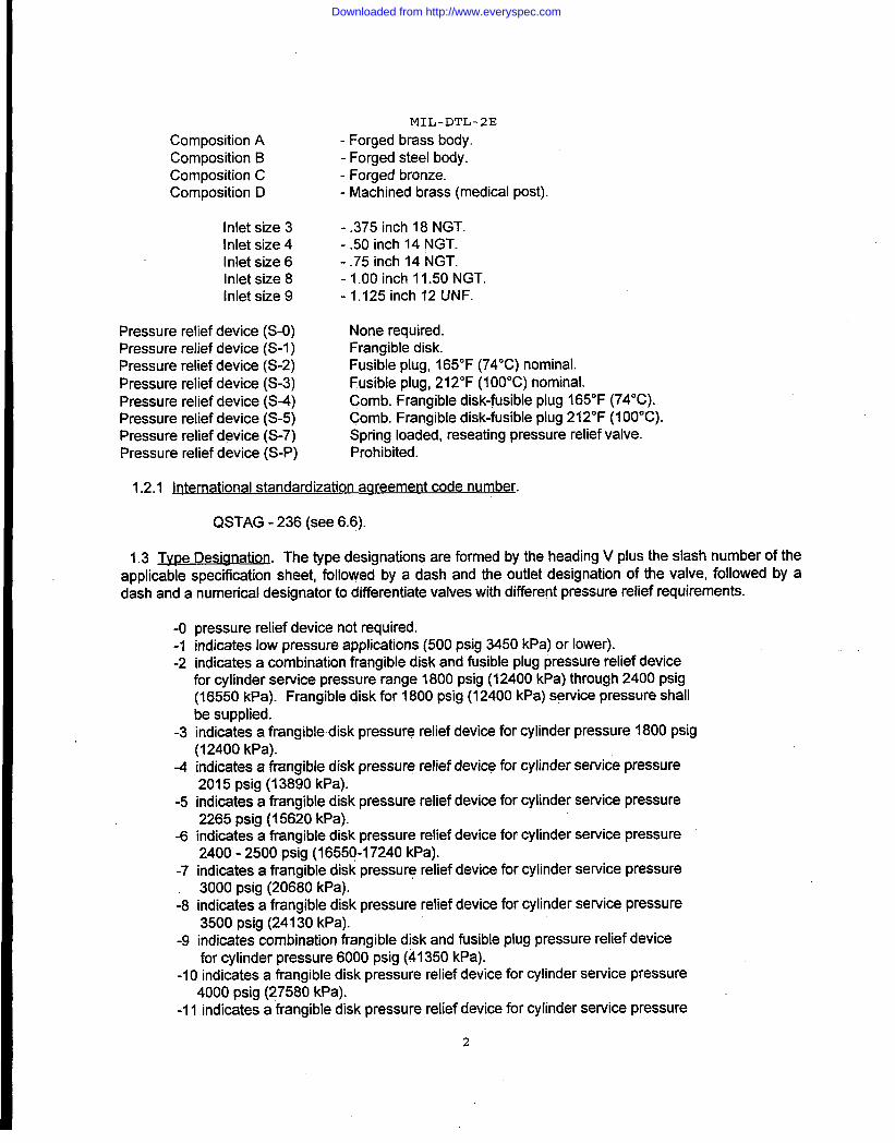
Composition AComposition BComposition CComposition D
Inlet size 3Inlet size 4Inlet size 6Inlet size 8Inlet size 9
MIL-DTL-2E
-Forged brass body.- Forged steel body.- Forged bronze.- Machined brass (medical post).
-.375inch 18 NGT.-.50 inch 14 NGT.-.75 inch 14 NGT.-1.00 inch 11.50 NGT-1.125 inch 12 UNF.
Pressure relief device (S-O) None required.Pressure relief device (S-1) Frangible disk.Pressure relief device (S-2) Fusible plug, 165°F (74°C) nominal.Pressure relief device (S-3) Fusible plug, 212°F (1OO”C)nominal.Pressure relief device (S-4) Comb. Frangible disk-@sible plug 165°F (74°C).Pressure relief device (S-5) Comb. Frangible disk-fusible plug 212°F (1OO”C).Pressure relief device (S-7) Spring loaded, reseating pressure relief valve.Pressure relief device (S-P) Prohibited.
1.2.1 International standardization aareement code number.
QSTAG -236 (see 6.6).
1.3 Tvpe Designation. The type designations are formed by the heading V plus the slash number of theapplicable specification sheet, followed by a dash and the outlet designation of the valve, followed by adash and a numerical designator to differentiate valves with different pressure relief requirements.
-o-1-2
-3
-4
-5
-6
-7
-8
-9
pressure relief device not required.indicates low pressure applications (500 psig 3450 kPa) or lower).indicates a combination frangible disk and fusible plug pressure relief devicefor cylinder service pressure range 1800 psig (12400 kPa) through 2400 psig(16550 kPa). Frangible disk for 1800 psig (12400 kPa) service pressure shallbe supplied.indicates a frangible disk pressure relief device for cylinder pressure 1800 psig(12400 kPa).indicates a frangible disk pressure relief device for cylinder service pressure2015psig(13890 kPa).indicates a frangible disk pressure relief device for cylinder service pressure2265 psig (15620 kPa).indicates a frangible disk pressure relief device for cylinder service pressure2400-2500 psig (16550-17240 kPa).indicates a frangible disk pressure relief device for cylinder service pressure3000 psig (20680 kPa).indicates a frangible disk pressure relief device for cylinder service pressure3500 psig (24430 kPa).indicates combination frangible disk and fusible plug pressure relief devicefor cylinder pressure 6000psig (41350 kPa).
-10 indicates a frangible disk pressure relief device for cylinder service pressure4000 psig (27580 kPa).
-11 indicates a frangible disk pressure relief device for cylinder service pressure
2
Downloaded from http://www.everyspec.com
MIL-DTL-2E
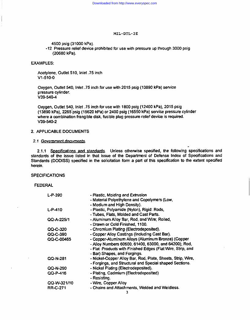
4500psig (31000 kPa).-12 Pressure relief device prohibited for use with pressure up through 3000 psig
(20680 kPa).
EXAMPLES:
Acetylene, Outiet 510, Inlet .75 inchV1-51O-O
Oxygen, Outlet 540, Inlet .75 inch for use with 2015 psig (13890 kPa) servicepressure cylinder.V39-540-4
Oxygen, Outlet 540, Inlet .75 inch for use with 1800 psig (12400 kPa), 2015 psig(13890 kPa), 2265”psig (15620 kPa) or 2400 psig (16550 kPa) service pressure cylinderwhere a combination frangible disk, fusible plug pressure retief device is muired.V39-540-2
2. APPLICABLE DOCUMENTS
2.1 Gove~nt documenfs.
2.1.1 -cations ~. Unless otherwise specified, the following specifications andstandards of the issue listed in that issue of the Department of De&nse Index of Specifications andStandards (DODISS) specified in the solicitation form a part of this specification to the extent specifiedherein.
SPECIFICATIONS
FEDERAL
L-P-390
L-P41 O
QQ-A-225J1
QQ-C-320QQ-C-390QQ-C-00465
QQ-N-281
QQ-N-290QQ-P+16
QQ-W-321I1ORR-C-271
- Plastic, Molding and Extrusion- Material Polyethylene and Copolymers (Low,- Medium and High Density).- Plastic, Polyamide (Nylon), Rigid: Rods,- Tubes, Flats, Molded and Cast Parts.- Aluminum Alloy Bar, Rod, and Wire; Rolled,- Drawn or Cold Finished, 1100.- Chromium Plating (Electrodeposited).- Copper Alloy Castings (lncJuding Cast Bar).- Copper-Aluminum Alloys (Aluminum Bronze) (Copper- AJloy Numbers 60600,61400,63000, and 64200); Rod,- Flat Products with Finished Edges (Flat Wire, Strip, and- Bar) ShaWs, and Forgings.- Nickel-Copper Alloy Bar, Rod, Plate, Sheets, Strip, Wire,- Forgings, and Structural and Special shaped Sections.- Nickel Plating (Electrodeposited).- Plating, Cadmium (Electrodeposited)- Resisting.- Wire, Copper Alloy- Chains and Attachments, Welded and Weldless.
3
Downloaded from http://www.everyspec.com
MIL-DTL-2E
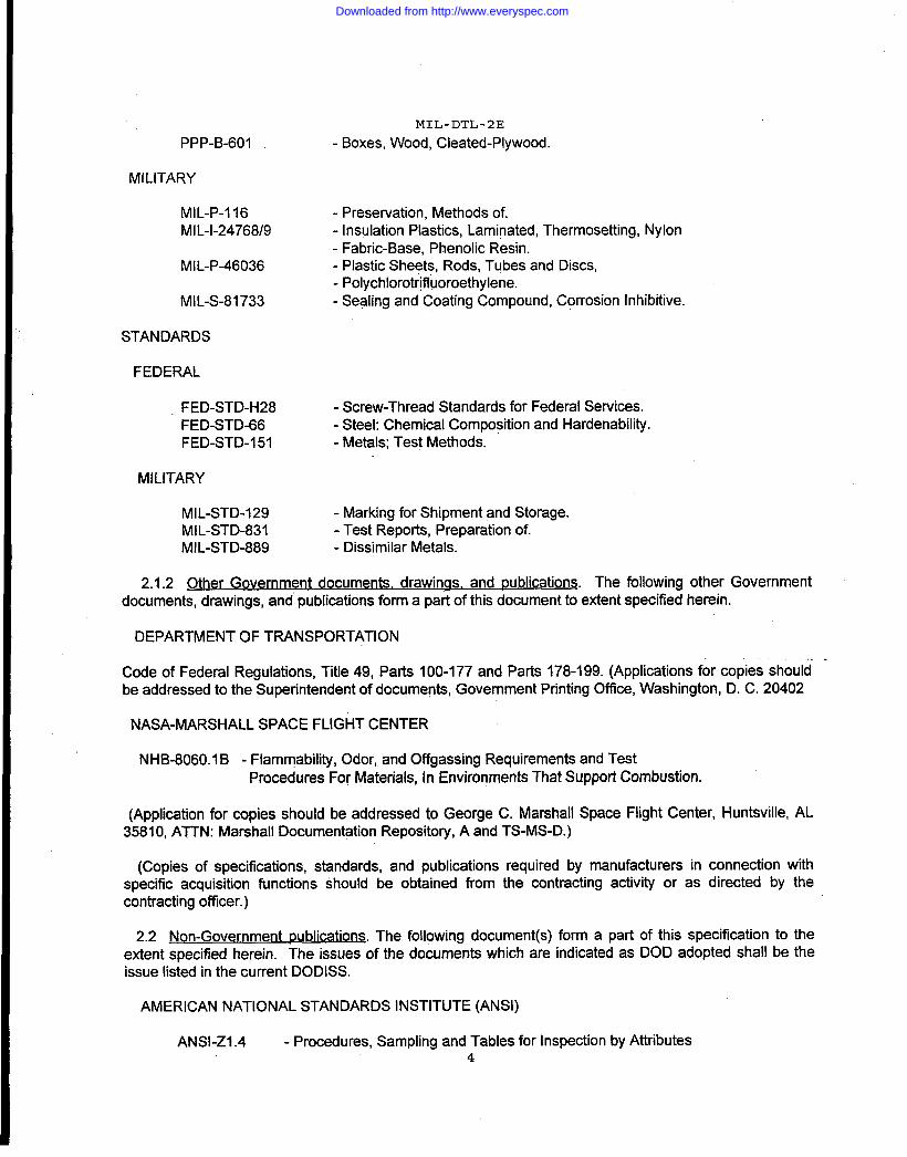
PPP-B-601 -Boxes, Wood, Cleated-Plywood.
MILITARY
MlL-P-l 16 - Presewation, Methods of.MIL-1-24768/9 - Insulation Plastics, Laminated, Thermosetting, Nylon
- Fabric-Base, Phenolic Resin.MIL-P46036 - Plastic Sheets, Rods, Tubes and Discs,
- Polychlorotfifluoroethylene.MIL-S-81733 .-Sealing and Coating Compound, Corrosion inhibitive.
STANDARDS
FEDERAL
FED-STD-H28 - Screw-Thread Standards for Federal Services.FED-STD-66 - Steel: Chemical Composition and Hardenability.FED-STD-151 - Metals; Test Methods.
MILITARY
MIL-STD-129 - Marking for Shipment and Storage.MIL-STD-831 - Test Reports, Preparation of.MIL-STD-889 - Dissimilar Metals.
2.1.2 Other Government documents. drawings, and publications. The following other Governmentdocuments, drawings, and publications form a part of this document to extent specified herein.
DEPARTMENT OF TRANSPORTATION
Code of Federal Regulations, Title 49, Parts 100-177 and Parts 178-199. (Applications for copies should. .
be addressed to the Superintendent of documents, Government Printing Office, Washington, D. C. 20402
NASA-MARSHALL SPACE FLIGHT CENTER
NHB-8060.1 B - Flammability, Odor, and Offgassing Requirements and TestProcedures For Materials, tn Environments That Supporl Combustion.
(Application for copies should be addressed to George C. Marshall Space Flight Center, Huntsville, AL35810, ATTN: MarshalI Documentation Repository, A and TS-MS-D.)
(Copies of specifications, standards, and publications required by manufacturers in connection withspecific acquisition functions should be obtained from the contracting activity or as directed by thecontracting officer.)
2.2 ~ ublications. The following document(s) form a part of this specification to theextent specified herein. The issues of the documents which are indicated as DOD adopted shall be theissue listed in the current DODISS.
AMERICAN NATIONAL STANDARDS INSTITUTE (ANSI)
ANSI-Z1.4 - Procedures, Sampling and Tables for Inspection by Attributes4
Downloaded from http://www.everyspec.com
.
MIL-DTL-2E
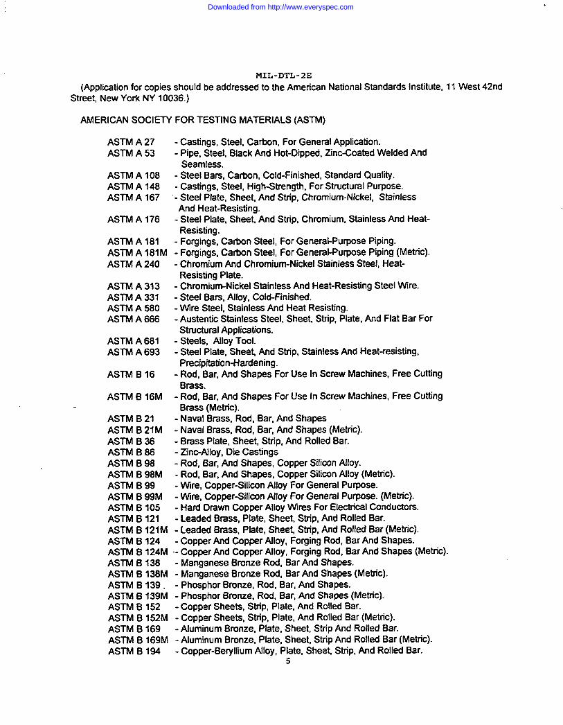
(Application for copies should be addressed to the American National Standards Institute, 11 West 42ndStreet New York NY 10036.)
AMERICAN SOCIEIV FOR TESTING MATERIALS (ASTM)
ASTM A 27 - Castings, Steel, Carbon, For General Application.ASTM A 53 - Pipe, Steel, Black And Hot-Dipped, Zinc-Coated Welded And
Seamless.ASTM A 108 - Steel Bars, Carbon, Cold-Finished, Standard Quality.ASTM A148 - Castings, Steel, High-Strength, For Structural Purpose.ASTM A 167 - Steel Plate, Sheet, And Strip, Chromium-Nickel, Stainless
And Heat-Resisting.ASTM A 176 - Steel Plate, Sheet And Strip, Chromium, Stainless And Heat-
Resisting.ASTM A 181 - Forgings, Carbon Steel, For General-Purpose Piping.ASTM A !81M - Forgings, Carbon Steel, For General-Purpose Piping (Metric).ASTM A 240 - Chromium And Chromium-Nickel Stainless Steel, Heat-
Resisting Plate.ASTM A 313 - Chromium-Nickel Stdnless And Heat-Resisting Steel Wire.ASTM A 331 - Steel Bars, Alloy, Cold-Finished.ASTM A 580 - Wire Steel, Stainless And Heat Resisting.ASTM A 666 - Austentic Stainless Steel, Sheet, Strip, Plate, And Flat Bar For
Structural Applications.ASTM A 681 - Steels, Alloy TOOLASTM A 693 - Steel Plate, Sheet And Strip, Stainless And Heat-resisting,
Precipitation-Hardening.ASTM B 16 - Rod, Bar, And Shapes For Use In Screw Machines, Free Cutting
Brass.ASTM B 16M - Rod, Bar, And Shapes For Use In Screw Machines, Free Cutting
Brass (Metric).ASTM B 21 - Naval Brass, Rod, Bar, And ShapesASTM B 21M - Naval Brass, Rod, Bar, And Shapes (Metric).ASTM B 36 - Brass Plate, Sheet Strip, And Rolled Bar.ASTM B 86 - Zinc-Alloy, Die CastingsASTM B 98 - Rod, Bar, And Shapes, Copper Silicon Alloy.ASTM B 98M - Rod, Bar, And Shapes, Copper Silicon Alloy (Metric).ASTM B 99 - Wire, Copper-Silicon Alloy For General Purpose.ASTM B 99M - W@ Copper-Silicon Alloy For General Purpose. (Metric).ASTM B 105 - Hard Drawn Copper Alloy Wires For Electrical Conductors.ASTM B 121 - Leaded Brass, Plate, Sheet Strip, And Rolled Bar.ASTM B 121M - Leaded Brass, Plate, Sheet Strip, And Rolled Bar (Metric).ASTM B 124 - Copper And Copper Alloy, Forging Rod, Bar And Shapes.ASTM B 124M - Copper And Copper Alloy, Forging Rod, Bar And Shapes (Metric).ASTM B 138 - Manganese Bronze Rod, Bar And Shapes.ASTM B 138M - Manganese Bronze Rod, Bar And Shapes (Metric).ASTM B139. - Phosphor Bronze, Rod, Bar, And Shapes.ASTM B 139M - Phosphor Bronze, Rod, Bar, And Shapes (Metric).ASTM B 152 - Copper Sheets, Strip, Plate, And Rolled Bar.ASTM B 152M - Copper Sheets, Strip, Plate, And Rolled Bar (Metric).ASTM B fi69 - Aluminum Btunze, Plate, Sheet, Strip And Rolled Bar.ASTM B 169M - Aluminum Bronze, Plate, Sheet Strip And Rolled Bar (Metric).ASTM B 194 - Copper-Be@ium Alloy, Plate, Sheet Strip, And Rolled Bar.
5
Downloaded from http://www.everyspec.com

ASTM B 283ASTM D 1229ASTM D 1710ASTM D 2000ASTM D 3951ASTM D 4066ASTM E 18ASTM G 37
MIL-DTL-2E
-Copper And Copper-Alloy Die Forgings (Hot-Pressed).- Rubber, Property-Compression Set At Low Temperatures.- TFE-Fluorocarbon Rod.- Rubber Products In Automotive Applications.- Packaging, Commercial.- Nylon Injection And Extrusion Materials.- Rockwell Hardness And Rockwell Superficial Hardness Metallic Materials.- Stress-corrosion cracking
(Application for copies should be addressed to the American Society for Testing and Materials, 1916Race Street, Philadelphia, PA 19103-1187.)
COMPRESSED GAS ASSOCIATION, INC.
Pamphlet S-1.1 - Pressure Relief Device Standards, Part 1- Cylinders ForCompressed Gases.
Pamphlet S-7 - Method For Selecting Pressure Relief Devices For Compressed GasMixtures In Cylinders.
Standard V-1 - ANSUCWVCGA, Compressed Gas Cylinder Valve Outlet And InletConnections.
Standard V-7 - Standard Method Of Determining Cylinder Valve Outlet ConnectionsFor Industrial Gas Mixtures.
THE CHLORINE INSTITUTE, lNC.
Drawing No. 110- Valve For Chlorine Cylinders And Ton Containers Assembly.Drawing No. 112- Valve And Fusible Plug For Chlorine Cylinders And Ton
Containers-Specifications And General Notes.Drawing No. 113- Valve For Chlorine Cylinders And Ton Containers-Parts.
(Non-government standards and other publi@ions are normally available from the organizations thatprepare or distribute the documents. These documents also may be available in or through libraries orother informational sewices.)
2.3 Order of Precedence. In the event of a conflict between the text of this document and the referencescited herein (except for related associated detail specifications, spe&cation sheets, or MS standards), thetext of this document takes precedence. Nothing in this document, however, supersedes applicable lawsand regulations unless a specific exemption has been obtained.
3. REQUIREMENTS
3.1 Specification sheets. The individual item requirements shall be as specified herein and inaccordance with the applicable specification sheet. In the event of any conflict between the requirementsof this specification and the specification sheet, the latter shall govern.
3.2 Qualification. The valves furnished under this specification shall be products which are qualified forlisting on the applicable qualified products list at the time set for opening of bids (see 4.3 and 6.5).
3.3 Reliability. The diaphragm valve shall have a reliability of not less than 2,000 cycles and all othervalves shall have a reliability of not less than 5,000 cycles. After having been opened and closed 2,000times or 5,000 times as applicable, at the maximum service pressure specified herein: The valve shall not
6
Downloaded from http://www.everyspec.com
MIL-DTL-2E
leak shallnot require an opening or closing torque greater than that specified herein; shall show noevidence of cracks, detaching, or failure of the seat disk insert or the stem tang when so equipped; andshall show no evidence of thread failure. The impression packed vatve shall not require tightening of thepacking nut or bonnet at intervals of less than 100 cycles. The diaphragm valve shall not requiretightening of any component at intervals of less than 2,000 cycles. The O-ring valve and the pressuresealed vatve shall not require tightening of any mmponent at less than 5,000 cycles.
3.4 fvlateria. Material shall be as specified herein. Materials not specified shall be selected by theContractor and shall be subject to all provisions of this specifmation.
3.4.1 J&&f@l det~ and w. The valves shall be fabricated from materials compatible withthe gas or product being used. Materials used shall be treated or processed toprovide protection againstthe various forms of corrosion and deterioration that may be enmuntered in any of the applicable storageand operating environment to which the item may be exposed.
3.4.1.1 ~. Dissimilar metals, as defined in MlLSfD889, shall be electrically insulatedfrom one another to minimize or prevent galvanic corrosion. Insulation may be provided by an insulatingbarrier such as a corrosion inhibiting sealant conforming to MIL+1733 or chromate tape conforming toZZ-R-765. Protection against corrosion could also be obtained by excJusion of the electrolyte if feasible.
3.4.~ .2 ~. The mntractor shall iden~ the specific material,material finish or treatment for use with components and sukomponents, and shall make informationavaifable, upon requesti to the contracting officer or designated representative. (see 6.2).
3.4.2 Recovered ~. For the purpose of this requirement recovered materials are thosematerials which have been collected tkom solid waste and reprocessed to become a source of rawmateriafs, as distinguished from virgin raw materials. The components, pieces and parts incorporated inthe valves may be newly fabricated from recovered materials to the maximum extent practicable, providedthe vafves produced meet all other requirements of this specification. Used, rebuilt or remanufacturedmmponents, pieces and pafi shall not be incorporated in the valw?s.
3.4.3 ~.
3.4.3.1 pie cast@s. Aluminum die castings shall conform to Alloy Numbers, 413.0, A413.0, or 360.0.
3.4.3.2 Flat sto&
3.4.5 m.
3.4.5.1 -.C84200 or C84400.
Flat aluminum stock shall conform to QQ-A-225/l, temper optional.
Brass castings shall conform to QQ-C-390, CDA Alloy Numbers C83600, C83800,
3.4.5.2 m. Forging brass shall conform to CDA Alloy Number C37700.
3.4.5.3 Free-c@@ Freeadting brass shall conform to CDA Alloy Number C36000.
3.4.5.4 w. Naval brass shall conform to CDA Alloy Number 48500.
3.4.5.5 miner m. Brass strainer wire shall mnform to QQ-W-321/10, CDA Alloy Number 27400.
3.4.6 j3ronze.
Downloaded from http://www.everyspec.com
MIL-DTL-2E
3.4.6.1 Aluminum. Aluminum bronze shall conform to QQ-C-O0465, CDAAlloy Number C63OOO.
3.4.6.2Aluminum-silicon. alloy B. Aluminum-silicon bronze, alloy B, CDAAlloy Number 64210 shallconform to Chlorine Institute Drawing Number 112.
3.4.6.3C64200.
3.4.6.4
3.4.6.5
Aluminum-silicon. Aluminum-silicon bronze shall conform to QQ-C-00465, CDA Alloy Number
Manaanese. Manganese bronze shall conform to ASTM B138, BI 38M.
Phosphor. flat stock. Phosphor bronze flat stock shall conform to ASTM BI 39, B139Mcomposition A or D, spring or extra spring temper.
3.4.6.6 Phosphor. round wire. Phosphor bronze round wire shall conform to QQ-W-321/l O, CDA AlloyNumber C51000.
3.4.7 Copper. Copper shall conform to ASTM B152, B152M, soil-annealed temper.
3.4.8 Copper alloys.
3,4.8.1 Be@lium. Copper-betyllium alloy shall conform to ASTM B194, CDA Alloy Number C17200.
3.4.8.2 Silicon. Copper-Silicon alloy shall conform to CDA Alloy Numbers C65100, C65500, C69200.
3.4.9 Nickel-copper alloy. Nickel-copper alloy shall conform to QQ-N-281.
3.4.10 Plastics.
3.4.10.1 Polvamide. Polyamide plastic shall conform to L-P41 O or ASTM D4066, compositions asspecified herein.
3.4.10.2
3.4.10.3
3.4.10.4
Polvethvlene. Polyethylene plast!c shall conform to L-P-390, Type 1, Class H, Grade 5.
Polvtetrafluoroethvlene. Polytetrafluoroethylene plastic shall conform to ASTM DI 710.
Phenol ic resins. Phenolic resin laminates shall conform to MIL-1-24768/9.
3.4.10.5 Polvchlorotrifluoroethvlene. Polychlorotrifluoroethy lene plastic shall conform to MIL-P-46036.
3.4.11 Rubber. Rubber shall conform to ASTM D 2000,designation 4BA820A14CI 2F19Z1Z2 with Z, orspecial requirements as follows: Z1-equivalent to suffix D of ASTM D 2000 table IV, with load of 20percent deflection to be 475 +/-100 psig (690 kPa); Z2-compression set after 22 hours at -50° F (45° C)shall be 70 percent (maximum) after 30 minutes recovery at -50° F (45”C) as per ASTM D 1229, withspecimens initially compressed 30 percent.
3.4.12 Steel—.
3.4.12.1
3.4.12.2
Carbon. Carbon steel bar stock shall conform to ASTM Al 08, UNS G10450.
-- Steel castings shall conform to ASTM fQ7i A148, ClaSS70-36.
8
Downloaded from http://www.everyspec.com
MIL-DTL-2E
3.4.12.3 Corrosion-resis@g bar stoc~. Corrosion-resisting steel bar stock shall conform to QQ-S-763,classes as specified herein.
3.4.12.4 Corrosion-reWtina wir?. Corrosion-resisting steel wire shall conform to ASTM A313, A580,compositions as specified herein.
3.4.12.4.1Corroskvwresk@gsheetand* stock.Corrosion-resisting sheet and strip stock shallconform to ASTM A167, Al 76, A240, A666, A693, classes as specified herein.
3.4.~2.5 Foraings. Steel forgings shall conform to ASTM A181, Class 70.
3.4.12.6 SteelW. Sieel alloy barstock shall conform to ASTM A 331, UNS G48200.
3.4.12.7 -Steel pipe shall conform to ASTM A 53, type S, grade ~ schedule number 40.
3.4.12.8 ml valves . The material used in all medical valves shall be in accordance with the latestrevision of NHB-8060.I.
3.4.13 m.
3.4.13.1 ~. Zinc die casting shall conform to ASTM B 86, Alloy optional.
3.5 Rg&@.Q.The valve shall be of a compression packed, an O-ring, pressure seal, or a diaphragm style.The vatve shall consist of a body with inlet and outlet a pressure relief device as required, internal
working parts, valve stem, seat bonnet or packing nut and packing as required. A handwheel or wrenchor key shall be furnished, as specified in the applicable specitlcation sheet An outiet cap or plug, withchain and retaining ring, shall be supplied when specified. A dip tube or eductor tube shall be furnishedinstalled in accordance with 3.6.1.6 when specified.
3.6.1.1 !&.Ne body. The valve body shall be as specified herein for the applicable vatve style, and asfollows.
3.6.1.1.1 M The inlet threads shall conform to FED-STD-H28. The thread symbol shall be asspecified in the applicable specification sheet. All valve bodies constructed from aluminum alloyconforming to QQ-A-225/l shall have straight threads. Valve bodies having a 0.375 inch (9.525 mm) or a0.50 inch (12.70 mm) inlet shall have an inlet channel clear opening, from the inlet to the seat of not lessthan the cross sm-onal area of a 0.125 inch (3.18 mm) diameter circfe. Atl other valve bodies shall havean inlet channel clear opening of not less than the cross sectional area of a 0.25 inch (6.35 mm) diametercircle. Unless otherwise specified in the applicable specification sheet, when the vafve is equipped W-ti adip tube the inlet shall be intemalty threaded to aooept the dip tube.
3.6.1.1.2 _ Unless otherwise specified in the applicable specification sheet the outtet shallconform to FENTD-H28, outlet number as specified in the applicable specification sheet.
3.6.1 .1.3 Pressure relief -ach @anfu?l. When a pressure retief devioe is specified in theapplicable specification sheet the approach channel shall be located between the inlet and valve seat.Valve bodies having a 0.375 inch (9.525 mm) or a 0.50 inch (12.70 mm) inlet shall have an approachchannel clear opening from the inlet channel to the pressure relief device, of not less than the cross
9
Downloaded from http://www.everyspec.com
MIL-DTL-2E
sectionalareaofa 0.125inch (3.18 mm) diameter circle. All other valve bodies shall have an approachchannel clear opening of not less than the cross sectional area of a 0.1875 inch (4.76 mm) diameter circle.In all cases the minimum flow requirements of CGA Pamphlet S-1.1 must be met.
3.6.1 .1.4 Valve seat. The valve seat shall have a clear opening of not less than the cross sectionalarea of a circle having a diameter as follows:
Valves used in liquefied gas service (class 05) 0.25 inch (6.35 mm)Valves having a 0.375 inch or a 0.50 inch inlet 0.0625 inch (1.59 mm)All other valves 0.125 inch (3.18 mm)
3.6.1 .1.5 Wrenchina surfaces. The body shall have two or more wrench flats. The wrench flats shallbe diametrically opposite each other and parallel to a plane determined by the centerlines of the valve inletand valve outlet. When the valve has a pin index outlet, the dimensions of the wrench flats shall conformto the body dimensions specified in FED-STD-H28. When the valve has a threaded outlet, the wrenchflats shall be accessible for the use of conventional cylinder valve wrenches in both manual and powerapplications without damage or deformation to any components of the valve.
3.6.1.2 ~. The stem material shall be as specified herein for the applicable valve style (see 3.9).The stem shall have a shank to fit a handwheel, a wrench or a key as specified herein and in theapplicable specification sheet. When used with a handwheel, the upper end of the stem shall be designedto transmit handle toque through the wrench flats or a spline and be either threaded externally to matewith a nut, or interflally for a machine screw for securing the handwheel. A positive mechanical fastenermay be used in lieu of a threaded fastener. When the stem is supplied with a disk insert, the insert shall fitin a counterbore in the bottom of the stem or in the bottom of the lower spindle of a two-piece stem. Theinseds shall conform to ASTM D4066, type 1 for polyamide plastics or MIL-1-24768/9 for phenolic-resinlaminates. Any lubricant applied to stems shall be compatible with the gas of intended use and shall besubject to approval of the qualification activity.
3.6.1.2.1 Stem hardness. Carbon steel, cast steel or nickel steel alloy stems used in compressionpacked valves shall have a Rockwell C surface hardness of not less than 30, to a depth of not less than0.020 inch (.508 mm) on the portion of @estem in contact with the packing.
3.6.1.3 Bonnet packina nut and packina washer. The bonnet packing nut and packing washer shall be asspecified herein for the applicable valve style. The bonnet packing nut shall be threaded to engage matingthreads on the valve body. Bonnet or packing nut surfaces which seal directly against the sealing materialshall be machined to provide a leak free seal. The bonnet packing nut shall be provided with wrenching flats.
3.6.1.4 Handwheel. The handwheel shall be a circular, oval or crossed spoke fingergrip type. Thehandwheel shall be not less than 2.50 inches (63.5 mm) and not greater than 2.75 inches (69.9 mm) indiameter. When used on a pressure seal valve, the handwheel shall bear against a tliction reducing thrustwasher located between the handwheel and the packing nut or bonnet. The handwheel shall be fabricated ofdie-cast zinc, die-st aluminum, or forged brass. Polyamide plastic handwheels 2.00 inches (50.8 mm) indiameter shall be acceptable for valves operating with opening and closing toque less than 60 inch pounds(6.78 Nm).
3.6.1.5 Strainer. When specified in 6.6, a strainer shall fit over or into a recess in the valve body inlet. Thestrainer shall not intetiere with the inlet threads nor be greater than 60 mesh metal screen. It shall befabricated of brass, nickel copper alloy, or composition 302 or 304 mrrosion-resisting steel wire.
3.6.1.6 Dip tube. The dip tube shall be 0.25 inch (6.35 mm) steel pipe unless otherwise specified. Oneend of the dip tube shall be externally threaded with 0.25-18 NPT threads conforming to FED-STD-H28. The
10
Downloaded from http://www.everyspec.com
MIL-DTL-2E
dip tube inlet shall be cut on a 45” angle. The dip tube shall be of sufficient length and shall be bent on asuitable radius so as to empty a cylinder of the specified length. When specified the dip tube shall befurnished assembled to the valve and secured in the opposite direction from the valve outlet by brazing or bysilver soldering.
3.6.1.7 Press ure refief devim. The pressure relief device shall be provided and installed as a unit by themntractor as required by the Dept of Transportation, Tiie 49, with its reference to CGA Pamphlet S-1.1. Thepressure relief device outlet cross ~“onal area and the cross sectional area of the approach channel in thevalve body shall be as specified in 3.6.1.1.3. The pressure relief device shall be of the type specified in theapplicable specitkation sheet
3.6.1.7.1 e 1. f@@&@&. The frangible disk pressure relief device shall mnsist of a frangibledisk, a sealing washer, and a cap or plug. Type 1 pressure relief devices shall be provided in valves forcyfinders subjected to filling pressures 10 percent above the permanently marked sewice pressure inaccordance with DOT CFR 173.302, (c).
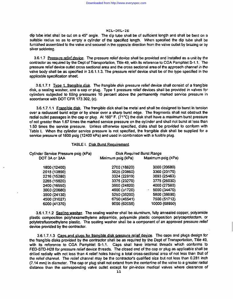
3.6.1 .7.1.1 ~. The frangible disk shall be metal and shall be designed to burst in tensionover a radiussed burst edge or by shear over a sharp burst edge. The fmgments shall not obstruct theradial outiet passages in the cap or plug. At 160° F. (71‘C) the disk shall have a maximum burst pressureof not greater than 1.67 times the marked service pressure on the cylinder and shall not burst at less than1.50 times the service pressure. Unless othetwise specified, disks shall be provided to conform withTable L When the cylinder service pressure is not specified, the frangible disk shall be supplied for asewice pressure of 1800 psig (12400 kPa) and used in combination with a fusible plug.
TABLE L Disk Burst ~.
Cyfinder Service Pressure psig (kPa) Disk Required Burst RangeDOT 3A or 3AA Minimum psig (kPa) Maximum psig (kPa)
1800 (12400)2015 (13890)2216 (15280)2265 (15620)2400 (16550)3000 (20680)3500 (24130)4500 (31027)6000 (41370)
2700 (18620)3025 (20860)3324 (22919)3375 (23270)3600 (24820)4600 (31720) .5250 (36200)6750 (46541 )9000 (62055)
3000 (20680)3360 (23170)3693 (25463)3775 (26030)4000 (27580)5000 (34470)5800 (39990)7500(51712)10000(68950)
3.6.1 .7.1.2 ~. The sealing washer shall be aiuminum, fully annealed copper, polyamideplastic composition polyhexamethylene adipamide, polyamide plastic composition polycaprolactam, orpolytetrafluomethylene plastic. The sealing washer shall be a component of an approved pressure reliefdevice provided by the contractor.
3.6.1.7.1.3 ~. .
The caps and plugs design fix
the frangible disks provided by the contractor shall be as required by the Dept of Transpmtation, Titfe 49,with its reference to CGA Pamphlet S-1.1. Caps shall have internal threads which conforms toFED-STDW28 for pressure relief device threads. The closed end of the cap or plug as applicable shall bedrilled radially with not less than 4 relief holes having a total cross-sectional area of not less than that ofthe relief channel. The relief channel may be the contractors qualified size but not less than 0.281 inch(7.14 mm) in diameter. The cap or plug shall not extend from the centerline of the valve to a greater radialdistance than the corresponding valve outlet except for pin-index medical valves where clearance of
11
Downloaded from http://www.everyspec.com
MIL-DTL-2E
standardyokesshallbethe limitingfactor.Caps andplugsshallredesignedtopreventblockageofreliefholesby fragmentationof frangible disks. Wrenching flats of caps or plugs shall be either 0.8125 or0.9375 inches (20.64 mm or 23.81 mm) diametrically across opposite surfaces.
3.6.1 .7.2 Tvpe 2. fusible plus. 165° F (74° C) nominal vie!d Doint. The type 2, fusible plug shall befabricated with fusible metal having a yield point between 157° F (69° C) and 170° F (77° C), (165° F (74°C) nominal). The plug shall be made of free-cutting brass or carbon steel stock as specified for the valvein the applicable specification sheet. The plug body shall be externally threaded in conformance withFED-STD-H28 for 0.125-27 NGT, 0.25-18 NGT or 0.375-18 NGT threads as specified. The clear throughopening in the plug shall be not less than 0.2187 inch (5.55 mm) in diameter except for medical postvalves when 0.1562 inch (3.97 mm) in diameter shall be acceptable. The external end of the plug shallhave a screwdriver slot, hexagonal wrenching flats or a hexagonal wrenching socket. Open ended plugsshall be either cone-bored, or straight-threaded to anchor the fusible metal for a leak-free metal-to-metaljuncture. Blind plugs with radially venting shall be straight bored with not less than 4 vent holes having atotal cross-sectional area not less than that of the cross-sectional area of the applicable relief channel.
3.6.1 .7.2.1 Fusible metal. (165° F (74° C) or 212° F (100° C) nominal). The fusible metal shallconform to CGA Pamphlet S-1.1 for fuse metal with yield points in the applicable range.
3.6.1 .7.2.2 Valve bodv drilled fusible plug. As specified in the applicable specification sheet apressure relief device, allowing a channel not less than 0.073 inch (1.85 mm) in diameter, shall be drilledand threaded into the valve body and filled with molten fusible metal effecting a leak-free plug.
3.6.1.7.3 Type 3. fusible dua. 212° F (1OO°Clnominal vield point. The type 3, 212° F (I OO”C)nominalyield point fusible plug pressure relief device shall be as specified for type 2, except that the fusible metalshall have a yield or melting point of not less than 208° F (98”C) and not greater than 220° F (104”C),(212° F (1OO”C)nominal)
3.6.1 .7.4 Type 4. combination franaible disk-fusible dua. 165° F [74°C 1nominal vield Doint. The type4, pressure relief device shall be as specified for type 1, except that the cavity beyond the frangible diskshall be filled with fusible metal having a yield or melting point of not less than 157° F (69° C) and notgreater than 170° F (77° C), (165° F (74° C) nominal). At 132° F (55° C) &2° F (1.110 C) the fusible metalcore shall not extrude and shall prevent the disk from bursting at its minimum burst pressure.
3.6.1.7.5 Tvpe 5. combination franaible disk-fusible tdua. 212° F (100° Cl nominal vield r)oint. Thetype 5 pressure relief device shall be as specified for type 4, except that the fusible metal shall have ayield or melting point of not less than 208° F (98° C) and not greater than 220° (104° C), (212° F (100° C)nominal).
3.6.1 .7.6 Type 7. Dressure relief device. The type 7, pressure relief device shall consist of a cap orplug insert, spring, and an insert retainer. Unless otherwise specified, the spring tension shall be adjustedso that the relief device shall start to discharge at not less than 75% and shall reseal at not less than 70%of the designated cylindets minimum test pressure. The device shall reach full flow position at not greaterthan 100% of the cylinder’s minimum test pressure. The flow capacity of the pressure relief device shallconform to Pressure Relief Device Standards Pamphlet S-1.1, of the Compressed Gas Association for thewater capacity of the cylinder of intended use. The pressure relief device shall not bind or seize whileopening and closing. When installed on the valve, the pressure relief device cap or plug shall be soldered,crimped, or otherwise mechanically locked to prevent tampering with the spring tension adjustment.
3.6.1 .7.6.1 Pressure relief device. cap or plug. The pressure relief device cap or plug shall befabricated from free-cutting brass. The exterior suiface of the cap shall be cylindrical. The cap or plug
12
Downloaded from http://www.everyspec.com

MIL-DTL-2E
shall provide a means for securing the cap or plug to the valve body and for adjusting the spring tension.The threads shall be right hand, UNS mnforming to FED-STD-H28.
3.6.1 .7.6.2 Pressure ~elief device SRI@. The pressure relief device spring shall be helical and shallbe fabricated of corrosion-resisting steel wire, conforming to ASTM A313, A580, compositions 302 or 304,condition B.
3.6.1 .7.6.3 ~~. The retainer shall have a shroud or guide surface to align the spring and aoounterbore to retain the insert.
3.6.1 .7.6.4 Pressure rel@f dev~. .
The pressure relief device insert seal shall be polyamideplastic, phenolic resin laminate or rubber meeting the stability provisions specified herein.
3.6.1.8 ~. When specified, valves with threaded outlets shall have a permanentmetal mating plug or cap in accordance with figures 1 and 2. The metal plug or cap shall be supplied withretaining chain and clip to secure the plug or cap to the valve. The metal plug or cap shall effectively sealthe vafve against leakage when tested as specified herein.
3.6.1.8.1 ~ua retai. .~. The vatve outlet cap or plug retaining chain shall consist
of two bronze wire rings connected by a brass safety chain. The ends of the wire forming the rings shaIlbe formed into eyes without twisting and shall be brazed or clipped together after the chain has beeninsetied in the eye. One ring shall fit with a sliding % in the ring groove of the outlet cap or plug. Theother ring shall fit loosely around the valve body immediately above the inlet connection threads inaccordance with figures 1 and 2. The retaining chain shall be of such length that it does not interfere withthe cylinder flange threads when the cap or plug is installed on the vatve outlet but shall be of sufficientlength to permit the cap or plug to hang over the cylinder flange threads when removed. VVhenspecified,a disposable dust cap or plug shall be furnished without retaining chain.
3.7 ~.. .
. . -.
3.7.1 Pressm. The vatve shall not leak and shall not deform at the pressures specitled in Table Il.When the valve is fully open, and hatf open, there shall be no leakage around the stem, between thepacking nut or bonnet and the body, at the inlet connection, at the outtet connection, nor at the pressurerefief device connection. There shalt be no leakage at the seat when the valve is closed at the specilkdtorque. The valve shall show no evidence of leakage, titlure or permanent deformation when subjected tospecified pressures.
3.7.fl.1 ~ssur~ Service pressure shall be as specified for a specillc cylinder application.Maximum service pressure shall be as specified for the applicable clasa (see Table 11).
TABLE IL ~.
Maximum service pressure Hydrostatic proof pressureVaive class psig kPa psig kPa
05 500 3447 833 574330 3000 20680 5000 3447040 4000 27580 6666 4596255 5500 37922 9166 6320075 7500 51712 12500 86187
13
Downloaded from http://www.everyspec.com
MIL-DTL-2E
I *Note: Fortesting purposes class 05valves with type Vll pressure relief devices shall have the safetycapped or plugged when the maximum service pressures are applied.
I 3.7.1.2Proof pressure. The proof pressure shall be applied hydrostatically. The proof pressure shallnot be less than 1.67 times the maximum se~ice pressure specified herein for the applicable class (see
I Table 11).
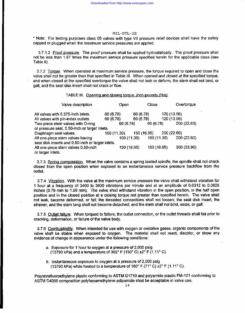
I3.7.2 Torque. When operated at maximum service pressure, the torque required to open and close the
valve shall not be greater than that specified in Table Ill. When opened and closed at the specified torque,and when closed at the specified overtorque the valve shall not leak or deform, the stem shall not bind, orgall, and the seat disk insert shall not crack or flow.
I TABLE Ill. en-n~).
I Valve description Open Close Overtorque
All valves with 0.375-inch inlets, 60 (6.78) 60 (6.78) 120 (13.56) “All valves with pin-index outlets. 60 (6.78) 60 (6.78) 120 (13.56)Two-piece stem valves with O-ring 60 (6.78) 60 (6.78) 200 (22.60)or pressure seal, 0.50-inch or larger inlets.Diaphragm seal valves. 100 (11.30) 150 (16.95) 200 (22.60)All one-piece stem valves having 100(11.30) 100 (11.30) 200 (22.60)seat disk inserts and 0.50-inch or larger inlets.All one-piece stem valves 0.50-inch 150 (16.95) 150 (16.95) 300 (33.90)or larger inlets.
3.7.3 Sprina commession. When the valve mntains a spring loaded spindle, the spindle shall not checkclosed from the open position when exposed to an instantaneous service pressure backflow from theoutlet.
3.7.4 Vibration. With the valve at the maximum service pressure the valve shall withstand vibration for1 hour at a frequency of 3400 to 3600 vibrations per minute and at an amplitude of 0.0312 to 0.0625inches (0.79 mm to 1.59 mm). The valve shall withstand vibration in the open position, in the half openposition and in the closed position at a closing torque not greater than specified herein. The valve shallnot leak, become deformed, or @Ii; the threaded connections shall not loosen; the seat disk insert, thestrainer, and the stem tang shall not become detached; and the stem shall not bind, seize, or gall.
I 3.7.5 Outlet failure. When torqued to failure, the outlet connection, or the outlet threads shall fail prior tocracking, deformation, or failure of the valve body.
I 3.7.6 ~. When intended for use with oxygen or oxidative gases, organic components of thevalve shall be stable when exposed to oxygen. The material shall not react, discolor, or show anyevidence of change in appearance under the following conditions:
I a. Exposure for 1 hour to oxygen at a pressure of 2,000 psig(13790 kPa) and a temperature of 302° F (150° C) *2° F (1.11° C).
I b. Instantaneous exposure to oxygen at a pressure of 2,000 psig(13790 kPa) while heated to a temperature of 160° F (710C) &2° F (1.1 10C).
I Polytetrafluoroethylene plastic conforming to ASTM D1710 and polyamide plastic FM-1OI conforming toASTM D4066 composition polyhexamethylene adipamide shall be acceptable in valve use.
14
Downloaded from http://www.everyspec.com
MIL-DTL-2E
3.8 ~1 reoumm~ . ~evalve shall wnfomto the following environmen~l requirements.
3.8.1 ~.
3.8.1.1 Qoeraw. The valve shall operate at the maximum service pressure specified for type andclass, and at an ambient temperature of -50° F (+5° C) @“ F (1.11“ C) without leaking or requiring anopening or closing toque greater than that specified in Table Ill and without damage or permanentdeformation of any component
3.8.1.2 a. The valve shall withstand storage at the maximum service pressure specified herein,for 8 hours at a temperature of 450° F (-51” C) &?” F (1.11° C) without leaking, when closed at a cfosingtorque not greater than that specfied in Table Ill and without damage or permanent deformation of anycomponents.
3.8.2 ~.
3.8.2.1 ~. The valve shall operate at the maximum service pressure specilied herein and atan ambient temperature of 120” F (49° C) W“ F (1.11” C), the vatve shall not leak, require an opening orcfosing toque greater than that specilled in Table Ill nor show any evidence of leakage, failure orpermanent deformation of any component
3.8.2.2 -. The valve shall withstand storage at a pressure of not less than the maximum sewicepressure specified herein, tir 8 hours at a temperature of 155° F (68.8” C) HO F (1.110 C) withoutleaking, when closed at a cJosing toque not greater than that specified in Table Ill and Whout failure orpermanent deformation to any mmponent
3.9 m ~. The valve styles and compositions shall be as follows.
3.9.1 style I valve. - Style I valve shall have a compression packed seal and shall be used for servicepressures not greater than 500 psig (3450 kPa), class 05, and compositions A, B, or C as specified in theapplicable specification sheet.
3.9.1.1 Unless otherwise specified in the applicable specification sheetthe impression packed vatve shall have a vertical stem and an outlet centerline at 90 degrees to thestem centerline. When specified in the applicable specification sheet the stem and outiet shall be suitablyangled. The compression packed valve shall have a on&piece stem except for medical post application.The stem or upper stem shall backseat in the fully open position. Sealing shall be by mmpressedpacking. The packing shall be mmpressed by tightening a threaded packing nut or bonnet The packingshall be mmpressed inside the valve body. The packing shall effect a seal against the chumferentialsurface of the stem and against the interior wall of the vatve body. The surfaces exerting compress.weforce against the packing may be angled so that the height of the packing bore is greater than the heightat the periphery of the packing. The bottom of the packing shall be seated against a shoulder in the valvebody oragainst a washer. The top of the packing shall be seated against a packing washer or against theend of the packing n@ except that a packing washer shall be used when the packing does not have an
“inherently low coefficient of friction. When specified in the applicable specification sheet the compressionpacked valve shall confbrm to Chlorine Institute Drawings No. 110, 112, and 113 except the outlet capshall be supplied with a retaining chain and ring as specified in 3.6.1.8.
3.9.1 .1.1 Style I - co~ A valve. Style I-A valve bodies shall be made of forging brass asspecified herein, with an integral seat to mate with a one-piece stem for a leak-free seal. In the fully openposition the stem shall backseat against the packing to inswe a leak-free seal at the packing-stem
1s
Downloaded from http://www.everyspec.com
MIL-DTL-2E
junction. Thestem shall bemadeof corrosion-resisting steel, class 302, 303, 304,416, or 420; carbonsteel, nickel-steel alloy, nickel-copper alloy, free-cutting brass or aluminum bronze; as specified herein.Carbon steel and nickel alloy steel stems shall be chromium plated (as per QQ-C-320class 1)or cadmiumplated (as per QQ-P-416 class I type Ii) to reduce friction and corrosion. The plating of the stem may beeliminated when either polyethylene, polyamide, or polytetrafluoroethy lene plastic is used as a packingmaterial, The packing shall be polyethylene plastic, polyamide plastic, or polytetrafluoroethy lene plastic asspecified herein for stable control of the gas as specified in the applicable specification sheet. Thepacking nut or bonnet, packing washer, pressure relief device and outlet cap or plug shall be made fromforging or free-cutting brass.
3.9.1 .1.2 Stvle I - comp osition B valve. Style I-B valve bodies shall be made of cast steel or forgedsteel as specified herein. The stem shall be one piece, machined to mate with valve seat to effect aleak-free seal. When specified in the applicable specification sheet the valve seat shall be an insert of99.5 percent pure tin firmly anchored to the valve body. When fully open the stem shall backseat againstthe packing effecting a leak-free seal at the stem-packing junction. The stem shall be made of carbonsteel or mrrosion-resisting steel, as specified herein. The class of corrosion-resisting steel shall be class302, 303, 304, 416, or 420. Packing shall be of materials listed for style I-A valve selected for stablecontrol of the gas setvice as specified in the applicable specification sheet. The packing nut or bonnet,packing washer pressure relief device and outlet cap or plug shall be made from carbon steel, castingsteel or forging steel.
3.9.1 .1.3 sty Ie I - compo sition C valve. Style I-C valve bodies shall be made of aluminum-siliconbronze, as specified herein. For chlorine service the valve body and components shall conform to drawingNos. 110, 112, and 113 by the Chlorine Institute for chlorine valves. For applications other than chlorineservice, aluminum-silicon bronze shall be as specified in 3.4.6.3, except iron, nickel, manganese, tin, zinc,and tellurium shall not be required. The body shall have an integral seat to mate with a one-piece stem.The stem shall be made of nickel-copper alloy or aluminum bronze. The packing shall be of materialslisted for style I-A valve selected for stable control of the gas service as specified in the applicablespecification sheet. The packing nut or bonnet, packing washer, pressure relief device and outlet cap orplug shall conform to the Chlorine Institute drawings above.
3.9. 1.f.4 Stvle I - composition D valve. Style I-D valve shall be for medical post (pin-index)applications and shall have a machined brass body. The.valve shall have a two-piece stem coupled by atang and slot or a stud and socket. The lower stem shall be made of freecutting brass or naval brass andfitted with an polyhexamethylene adipamide plastic seat insert, which shall mate with a machined. seat inthe valve body. The lower stem shall be threaded to mate threads in the valve body and when turnedclockwise, shall close the valve for a leak-free seal. The upper stem shall be made of free-cutting brass,naval brass or corrosion-resisting steel as specified herein and packed with a polytetrafluoroethy leneplastic and compressed with a brass packing nut&o effect a leak-free packing to stem junction. The upperstem may be spring loaded against the pacl@g to effect the seal. The packing nut or bonnet, packingwasher, and pressure relief device shall be made from free-cutting brass or forging brass.
3.9.2StvleIIvalve.StyleIIvalve shall be of the O-ring seal design and shall be used for sewicepressures not greater than 500 psig (3447 kPa).
3.9.2.1 O-rina valve. The O-ring valve shall have a one-piece or a two-piece stem. The stem shallhave a groove to retain the O-ring. The groove shall be designed so that the O-ring rolls between thestem’ and the body as the stem is raised or lowered. The O-ring shall effect a seal against a finishedsurface inside the valve body or the bonnet. The lower end of the bonnet shall seal against a shoulderinside the valve body by means of a metal-to-metal seal or a sealing washer. The stem shall backseatagainst the bonnet when in the fully open position.
16
Downloaded from http://www.everyspec.com

MIL-DTL-2E
3.9.2.1.1 Style II - composition A valve. Style II-A valve bodies shall be made of forging brass. Thebody shall have an integral seat to mate with the disk insert in the lower end of the stem. The o-ring sealshall be of sufficient thickness to create a compressive sealing pressure between the bottom of the stemgroove and the interior wall of the valve body or bonnet The compressive pressure shall cause the O-ringto roll on itseff when the stem is raised or towered in the valve body. The O-ting shall be rubber. Theone-piece, O-ring sealed stem shalt be threaded to close when turned clockwise. The stem shall have asurface for backseating in the fully open position. The stem shall have a groove to retain the O-ring. l%egroove shall be designed to permit the O-ring to roll on itself. The stem shall be fabricated ofcorrosion-resisting steel, nickel-copper alloy, fre=utting brass, or aluminum bronze. Corrosion-resistingsteel shall be class 302, 303, 304, 416, or 420. The upper stem of the two-piece, O-ring sealed stem shallbe threaded to close the valve when turned chckwise. The upper stem shall backseat against the bonnetwhen in the fully open position. The upper stem shall be counterbored, internally grooved, and gated toaccommodate a mating ftanged stub on the lower stem or spindle. Opening and closing action shall betransmitted to the spindle through the flanged stub. The spindle shall not rotate while being opened orclosed. The lower stem shall have a groove to retain the 0-ring. The groove shall be designed to permitthe O-ring to roll on itself in the groove. The spindle shall have a disk insert. The upper stem and thespindle shall be fabricated of cmrosion-resisting steel, free-cutting brass, nickel-copper alloy, or aluminumbronze. Corrosion-resisting steel shall be class 302, 303, 304, 416, or 420. The packing nut or bonnetpacking washer, pressure relief device, and outlet cap or plug shall be made from forging or ftee-cuttingbrass.
3.9.3styleIllvalve.StyleIllvafves shall be of the pressure seal design and shall be used inapplications not greater than 7500 psig (51712 kPa).
3.9.3.1 Pressure sea&j valve. The pressure sealed valve shall have a two-piece stem. The upperstem shall be spring loaded .s0 that an integral seating surface on the stem is backseated constantlyagainst the packing. The packing shall be seated against a countert)ore or a finished surke in tiepacking nut or bonnet and against a shoulder in the valve body. The upper stem and the packing shall bedesigned so that spring-pressure backseating of the upper stem is aided by internal gas pressure whenthe valve is in service. Style 111,class 05, shall further resist leakage when used in low pressure service.The lower stem or spindle shall be threaded to mate with threads in the valve body. The lower stem shallbe driven by a tang and slot connection or by a socket and shank connection.
3.9.3.1.1 Ill - ~. .
Style III-A valve bodies shall be fabricated of forging brass asspecified herein. The body shall have an integral seat to mate with the stem disk insert The upper stemand the seat plug shall be fabricated of corrosion-resisting steel, aluminum bronze, manganese bronze,copper-silicon alloy, naval brass, or fre~utting brass, as specified herein. Comosion-resisting steel shallbe class 302, 303, or 304. The upper stem spring shall be phosphor bronze wire or corrosion-resistingsteel w“re. Corrosion-resisting steel wire shall be composition 302 or 304, condition 6. The seal shall fit ina counterbore in the bonnet or packing nut. The packing shall seal against a shoulder in the vatve andagainst a mating surface in the bonnet or packing nut. The packing shall be polyamide plastic,composition polyhexamethylene adipamide, or shall be polytetrafluoroethylene plastic. The valve shallhave a tw~iece, pressure sealed stem. The upper stem shall have a backseating surface which shallseal against the packing. The backseated seal shall be maintained by spring pressure and shall besupplemented by gas pressure when the vatve is in service. Spring pressure shall be maintained by ashrouded spring fitted in a counterbore in the top of the handwheel, or by a spring inside the valve body.The upper stem shall drive the lower stem or plug by a slot and tang connection, or by a socket and shankconnection. The tang may be integral to a corrosion-resisting steel or naval brass stem or shall be madeof corrosion-resisting steel, class 302, 303, or 304. When not integral to the stem, the tang shall beattached to the upper stem. The socket and shank connection shall consist of a square or a prismaticsocket in the upper or the lower stem, and a mating shank on the other stem. The lower Stem or plugshall be threaded to close when turned clockwise. The lower stem shall have a disk insert. The packing
17
Downloaded from http://www.everyspec.com
MIL-DTL-2Enut or bonnet, packing washer, pressure relief device, and outlet cap or plug shall be made form free-cutting brass or forging brass.
3.9.4StyleIVvalve.StyleIVvalvesshall be of the diaphragm seal design. The diaphragm shall beused for applications up to 3000psig (20680kPa)service pressure.
3.9.4.1Dia~hraamvalve. The diaphragm valve shall have a threaded upper stem which, when turnedclockwise, shall depress a lower stem or spindle onto a valve seat. Action shall be transferred through asealed diaphragm located between the upper stem and the spindle. When the upper stem is turnedcounter-clockwise, the spindle shall be raised from the seat by a spindle spring. The diaphragm shall beimpression sealed between a lip or shoulder in the body and a mating surface in the bonnet.
3.9.4.1.1StyleIV-composition A. Style IV-A valve bodies shall be fabricated of forging brass. Thebody shall have an integral seat to mate with the stem disk insert. During opening and closing of thevalve, the spindle spring shall not inhibit the spindle movement and shall not bind in the valve body. Thespring shall be retained in position by machined seats, by a bushing, by a spindle guide, or by acombination of these. The spindle shall have a disk insert. The upper stem and the spindle of thediaphragm sealed valve shall be fabricated of corrosion-resisting steel, aluminum bronze,aluminum-silicon bronze composition 1, manganese bronze, copper-silicon alloy, free-cutting brass ornaval brass. Corrosion-resisting steel shall be class 302, 303, or 304. The bushing and the spindle guidewhen applicable shall be fabricated of free-cutting brass, naval brass, or corrosion-resisting steel.Corrosion-resisting steel shall be class 302, 303, or 304. The spindle spring shall be phosphor bronzewire or corrosion-resisting steel wire. Corrosion-resisting steel wire shall be composition 302 or 304,condition B. The diaphragm shall be impervious to gas from inlet service pressure and from outlet backpressure in the fully open position, the half open position, and the closed position. The diaphragm shallconsist of one or more plastic, rubber, or metallic elements. Metallic elements shall be corrosion-resistingsteel flat wire, phosphor bronze flat stock, copper-be~llium alloy, or nickel silver alloy. Corrosion-resistingsteel shall be composition 302, 303, or 304. For valves in class 30 and higher, only metallic diaphragmsshall be allowed. The bonnet or packing nut, packing washer, pressure relief device and outlet cap or plugshall be made from free-cutting brass or forging brass.
3.9.4.2 Style IV - comp osition D. Style IV-D valve bodies shall be fabricated of free-cutting brass. Thebody shall have an integral seat to mate with the stem disk insert of polyamide plastic for medical postapplication. The stem, bushing and spring of the style IV-D valve shall be as specified for the style IV-Avalve. The bonnet or packing nut, packing washer. pressure relief device and outlet cap or plug shall bemade from free-cutting brass or forging brass. The diaphragm seal shall be as specified for the style IV-Avalve, except only metal diaphragms shall be allowed.
3.10 Dimensions. Unless otherwise specified, the overall length of the valve shall not be greater than 5inches (127 mm). When equipped with a dip tube, the dip tube shall not be included as part of the overalllength. When the valve has a pin<ndex outlet, the maximum projection of the valve from the centerline ofits inlet connection shall not be greater than 0.9375 inches (23.81 mm). The maximum projection of athreaded outlet valve, including the outlet cap or plug, from the centerline of the inlet connection shall notbe greater than 1.625 inches (41.28”mm) and the maximum overall width of the valve shall not be greaterthan 3.0625 inches (77.79 mm).
3.11 Weight. When the valve has a pin-index outlet, the weight of the valve shall not be greater than 16ounces (453.6grams). When the valve has a threaded outlet the weight of the valve including the outletcap or plug shall not be greater than 40 ounces (1134 grams).
3.12 Finish. All valve bodies shall be finished in the base metal of fabrication except that unlessotherwise specified, valves for medical use shall be chromium over nickel plated. Chromium plating shall
18
Downloaded from http://www.everyspec.com
MIL-DTL-2E
conform to QQ-C-320, class 1, type I and thickness shall be 0.00001 inch (0.00025 mm) minimum.Chromium plating shall be applied over intermediate nickel coatings. Intermediate nickel coating shallmnform to QQ-N-290, class 1, grade G for brass and steel valve bodies. When subjected to a salt spraytest for 72 hours, the chromium plated valves shall show no evidence of corrosion, pitting or flaking. Thebottom of the valve inlet connection including five to eight threads shall be left unplated.
3.13 &lad@g. The valve shall be identified as specified below.
3.13.1 Body markii. The valve shall be permanently marked by etching, stamping or embossing. Theuse of nonmrrosive metal tags or durable plastic tags is not acceptable for valve identification in lieu ofmarking. Marking in the metal shall not be less than 0.0156 inch (0.396 mm) nor greater than 0.0312 inch(0.792 mm) in depth. Markings shall not be less than 0.0937 inch (2.38 mm) high except on valves with0.375 inch (9.52 mm) inlet when 0.0625 inch (1.59 mm) high lettering will be acceptable. Markings in themetal shall be on a plane parallel to a plane determined by the centerlines of the valve inlet and the valveoutlet Markings sha!l include the following:
a. The manufacturer’s identification.
b. Valves required for use with a specific gas shall be markedwith the name of the gas on at least one side of the vatvebody as specitled in the applicable specification sheet
c. Unless otherwise specified, valves required for use with a gaswithin one of the following groups of mmpatible gases (LPG,REFRIGERANT AND INERT) shall be marked with the group nameinstead of the name of the specific gas.
3.13.3.1 ml vafv~ Ail medical valves shall be ma~ed permanently by stamping or embossingthe metal surface. Each vatve shall cany the till name of the gas of intended use. Each valve shall bemarked “MED” not less than 0.125 inch (3.18 mm) high. If there is insufficient area to mark the full nameof the gas, the valve shall be stamped or embossed with the CGA mnnection number.
3.13.2 ~. The direction of rotation for opening the valve shall be marked on the handwheel byembossing or by stamping.
3.13.3 ~. When the vatve contains a pressure relief device with a frangible dislc themaximum burst pressure shall be stamped on the face of the cap of the pressure relief device.
3.f13.4 ~. When the valve contains a pressure relief device with fusible metal, thenominal yield temperature of the fi,rsible metal shall be stamped on a face of the device except for medicalpost (pin-index) valves, or when the fusible metal is poured into place in the vatve body in accordance w“tithe applicable specification sheet
3.13.5 ~ When the valve contains a spring-loaded pressure relief device, the start tod~charge pressure and the flow capacity in cubic feet per minute or a representative code shall bestamped on the device.
3.14 ~. All parts, components, and assemblies of the valve including castings, forgings,molded parts, stampings, seals, and machined surfaces shall be clean and free from sand, dirt, fins, pits,sprues, scale, and other harmful extraneous material. All edges shall be rounded or chamfered.
19
Downloaded from http://www.everyspec.com
MIL-DTL-2E
4. QUALITY ASSURANCE PROVISIONS
4.1 ~. Unless otherwise specified in the contract or purchase order, thecontractor is responsible for the performance of all inspection requirements as specified herein. Except asotherwise specified in the contract or purchase order, the contractor may use his own or any facilitiessuitable for the performance of the inspection requirements specified herein, unless disapproved by theGovernment. The Government reserves the right to perform any of the inspections set forth in thespecification where such inspections are deemed necessary to assure supplies and setvices conform toprescribed requirements.
4.1.1 Comoonent and material inspection. The contractor is responsible for insuring that componentsand materials used are manufactured, examined, and tested in accordance with referenced specificationsand standards.
4.2 Classification of inspection. The inspection requirements specified herein are classified as follows:
‘. a. Qualification inspection (see 4.3 and 6.3).b. Quality conformance inspection (see 4.4).c. Inspection of packaging (see 4.6).
4.3Q~. Five valves of each style and composition as applicable shall be submittedfor qualification inspection (see 6.3). When different forgings are utilized to accommodate various outletconnections, valves shall be submitted for each forging. Identical valves with varying outlets shall bequalified without need of individual testing. Each valve outlet shall be identified by two scale drawingssubmitted by the contractor in the Qualification Test RepoR (see 4,3.3). When the intended use of thevalve dictates that it be equipped with a pressure relief device, each valve shall be complete with apressure relief device. For valve styles Ill and IV where more than one type of pressure relief device isrequired to meet all intended uses of the basic valve, two of the additional pressure relief devices shall besubmitted. When frangible disks are required for different service pressures, two disks for each of theservice pressuresshall be submitted for testing in accordance with 3.6.1.7.1.1, as specified in 4.5.2.3. .
4.3.1 &@.mT@D. Each valve shall be examined as specified in 4.5.1. Presence of one or moredefects shall be cause for rejection.
4.3.2 Tests. Four valves of each classification shall be tested as specified in 4.5.2.1 through 4.5.2.19as applicable for the style, class and composition. The fifth valve shall be used as a test control. Failureof any test shall be cause for rejection.
4.3.3 Test report. After mmpleting the qualification tests, a test report shall be prepared in accordancewith MIL-STD-631 and three copies furnished to the qualification activity.
4.4Q~ r nce inspection.
4.4.1 Examination. Individual valves shall be examined for defects as specified in 4.5.1. Presence ofany defect shall be cause for rejection of the valve.
4.4.2 -. Samples for inspection and acceptance shall be in accordance with ANSI-ZI .4. Anydeparture from a specified requirement shall be classified as a defect. Any defect shall be cause forrejection of the entire lot.
4.5 Inspection procedures.
20
Downloaded from http://www.everyspec.com
MIL-DTL-2E
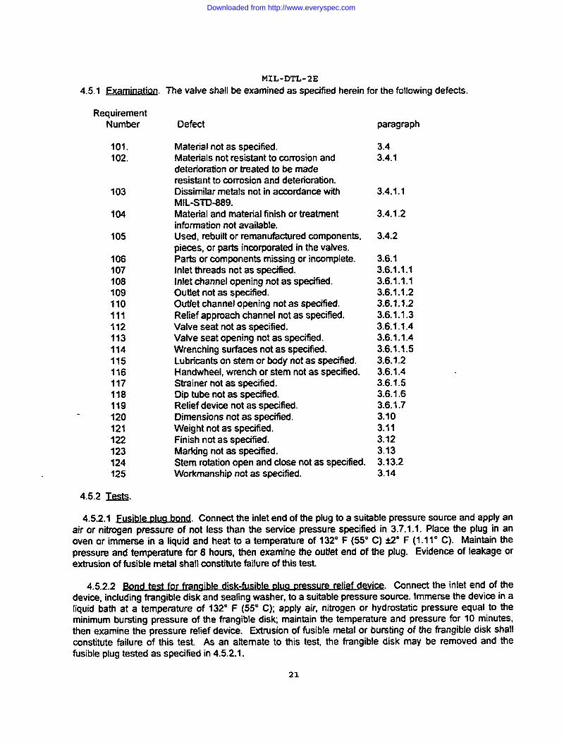
4.5.1 ~. The valve shall be examined as specified herein for the following defects.
RequirementNumber
101.102.
103
104
105
106107108109110111112113114115116117118119120121122123124125
4.5.2 m.
Defect
Material not as specified.Materials not resistant to corrosion anddeterioration or treated to be maderesistant to corrosion and deterioration.Dissimilar metals not in accordance withMIL-STD-889.Material and material finish or treatmentinformation not availab!e.Used, rebuilt or remanufactured components,pieces, or parts incaporated in the valves.Parts or components missing or incomplete.Inlet threads not as specitled.Inlet channel opening not as specified.Outfet not as specified.OutJet channel opening not as specified.Relief approach channel not as specified.Valve seat not as specified.Valve seat opening not as specified.Wrenching surfaces not as specified.Lubricants on stem or body not as specified.Handwheel, wrench or stem not as specified.Strainer not as specified.Dip tube not as specilied.Relief device not as specified.lXmensions not as specified.Weight not as specified.Finish not as specified.Marking not as specified.Stem rotation open and close not as specified.Workmanship not as specified.
paragraph
3.43.4.1
3.4._l.l
3.4.1.2
3.4.2
3.6.13.6.1.1.13.6.1.1.13.6.1.1.23.6.~.l.23.6.1 .1.33.6.1.1.43.6.1.1.43.6.1.1.53.6.’1.23.6.1.43.6.1.53.6.1.63.6.1.73.103.113.123.133.13.23.14
4.5.2.1~. Connect the inlet end of the plug to a suitable pressure source and apply anair or nitrogen pressure of not less than the service pressure speoified in 3.7.1.1, Place the plug in anoven or immerse in a liquid and heat to a temperature of 132° F (55° C) i2° F (1.11° C). Maintain thepressure and temperature fix 8 hours, then examine the outlet end of the plug. Evidence of leakage orextrusion of fusible metal shall constitute fdlure of this test.
4.5.2.2 st for ~ure relkMW@. Connect the inlet end of thedevice, including frangible disk and sealing washer, to a su-tible pressure source. Immerse the devioe in aliquid bath at a temperature of 132° F (55° C); apply air, nitrogen or hydrostatic pressure equal to theminimum bursting pressure of the frangible dislq maintain the temperature and pressure for 10 minutes,then examine the pressure retief device. Extrusion of fusible metal or bursting of the tlangible disk shallconstitute failure of this test As an alternate to this test, the frangible disk may be removed and thefusible plug tested as specified in 4.5.2.1.
21
Downloaded from http://www.everyspec.com

MIL-DTL-2E4.5.2.3Franaibledisk. This test shall be performed with no fusible metal backing the frangible disk.
Close the valve and plug or cap the outlet. Maintain a constant temperature of 160° F (710 C) at the valve.Subject the valve to an internal gas pressure, equal to the applicable service pressure of the valve, for 30
seconds. Raise the internal pressure at a rate of 50 psig (345 kPa) every 30 seconds until the frangibledisk bursts. Note the pressure at which the disk fails. Examine the cap or plug for obstruction of the outletpassages. Nonconformance to 3.6.1,7.1.1 shall constitute failure of this test. Test may be performed atroom temperature, provided that the relation of bursting pressure at room temperature to the burstingpressure at 160° F (710 C) has been established by previous tests. Ai7terhaving successfully tested twofrangible disk holders (cap or plug) of like design and dimension, any required additional tests of frangibledisks may be performed in a hardened steel fixture having a pressure opening identical in dimensions andconfiguration to that of the frangible disk holder in which the disk is to be used.
4.5.2.4Yieldtem~eraturetestfor fusible metal before DOurina into twessure relief device. Prepare twosticks from each batch of fusible metal. Each stick shall be 8 inches (203.2 mm) long. Cut 2-inch (50.8mm) specimens from the sticks and suspend two specimens on knife-edge supports. The supports shallbe l-inch (25.4 mm) apart. The specimens shall overhang the supports by 0.50 inch (12.7 mm). Thespecimens and supports shall be immersed in a glycerin Or oil bath. There shall be clearance of not lessthan 0.25 inch (6.35 mm) between the specimens and the bottom of the bath. The bath shall besuspended in and the temperature controlled by an outer glycerin or oil bath. A thermometer shall besuspended midway between the two specimens and shall not touch the bottom or the bath. Thetemperature of the bath shall start at 5° F (-15° C) below the lower rating of the fusible metal yield pointrange. From this temperature, raise the temperature of the bath at a rate of 10F (.56° C) every 3 minutes.The yield temperature shall be taken as that temperature at which the second of the four ends of the
specimens loses its rigidity and drops. A yield temperature that does not fall within the rated range of thefusible metal as specified @3.6.1.7.2.1, 3.6.1 .7.4 or 3.6.1 .7.5 as applicable, shall constitute failure of thistest.
4.5.2.5 Y~ ressure relie devices. Remove the frangible disk, if oneis present, from the pressure relief device. Suspend the device, with the centerline of the fusible metalvertically in an oil or glycqin bath. The bath shall be equipped with a mechanical stiner and not less thantwo thermometers of the bulb-immersion type. At any given time, the temperature of the bath shall beuniform. At the time of immersion, the temperature of the bath shall be 5° F (-15° C) below the lowerrating of the fusible metal yield range. Increase the temperature at the rate of 10 F (.56° C) evefy 3minutes. At every increase in temperature, pass the bulb of a thermometer across the surface of thefusible metal. Note the temperature when the bulb dips into the fusible metal. At this temperature, thefusible metal has become fluid. A temperature reading (at which the fusible metal becomes fluid) thatdoes not fall within the yield range specified in 3.6.1.7.2.1, 3.6.1.7.3, 3.6.1.7.4, or 3.6.1 .7.5 as applicableshall constitute failure of this test. Where the fusible metal is part of a nonremovable pressure reliefdevice, the test specified in 4.5.2.4 shall be used.
4.5.2.6 Sprina-loaded pressure relief device. Cap or plug the valve outlet. Open the valve. Connect thevalve inlet to an air source having a thermometer, a pressure gage, and provisions for metering the airflow. Immerse the valve in water, apply 300 psig (2070 kPa) of air at 70° F (210 C) and examine the reliefdevice for leaks. Increase the air pressure on the valve until the pressure relief device opens. Determinethe air pressure at which the relief device opens.” Determine the flow rate of air in cubic feet per minutethat escapes through the relief device after the valve internal pressure has been increased to 100% of thedesignated cylinder’s minimum test pressure at ambient temperature of 70° F (210 C). Decrease theinternal pressure until the relief device has resealed. Determine the internal pressure at which the reliefdevice resealed. Nonconformance to 3.6.1.7.6 shall constitute failure of this test.
22
Downloaded from http://www.everyspec.com
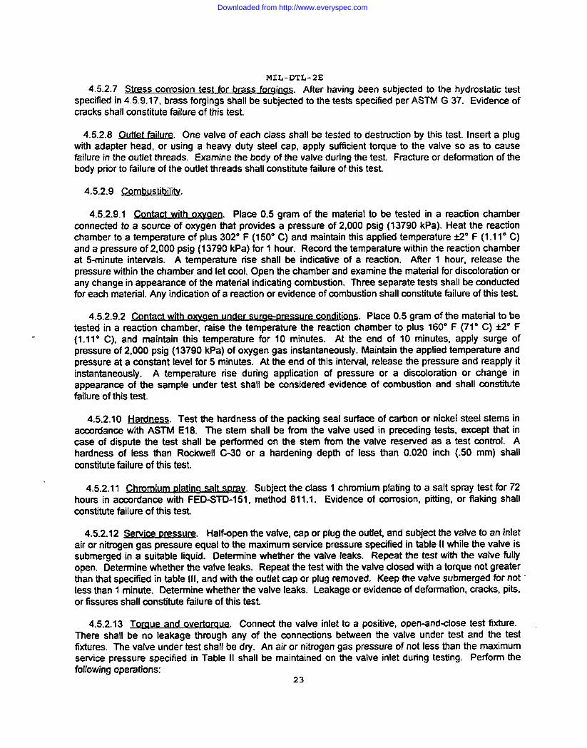
MIL-DTL-2E4.5.2.7 Stress corrosjjgm test for b~. After having been subjected to the hydrostatic test
specified in 4.5.9.17, brass forgings shall be subjected to the tests specified per ASTM G 37. Evidence ofcracks shall constitute failure of this test.
4.5.2.8Outfetfailure. One valve of each class shall be tested to desbwtion by this test Insert a plugwith adapter head, or using a heavy duty steel cap, apply sufficient torque to the valve so as to causefailure in the outlet threads. Examine the body of the valve during the test Fmture or deformation of thebody prior to failure of the outlet threads shall constitute failure of this test
4.5.2.9 Cornbustib~.
4.5.2.9.1 Place 0.5 gram of the material to be tested in a reaction chamberconnected to a source of oxygen that provides a pressure of 2,000 psig (13790 kPa). Heat the reactionchamber to a temperature of plus 302° F (150° C) and maintain this applied temperature ti” F (1.11° C)and a pressure of 2,000 psig (13790 kPa) for 1 hour. Record the temperature within the reaction chamberat 5-minute intewals. A temperature rise shall be indicative of a reaction. After 1 hour, release thepressure within the chamber and let cool. Open the chamber and examine the material for dismloration orany change in appearance of the material indicating combustion. Three separate tests shall be conductedfor each material, Any indication of a reaction or evidence of combustion shall constitute failure of this test.
4.5.2.9.2~ure @X@l@DS..
Place 0.5 gram of the material to betested in a reaction chamber, raise the temperature the reaction chamber to plus 160° F (71° C) i2° F(1.1 1° C), and maintain this tempemture for 10 minutes. At the end of 10 minutes, apply surge ofpressure of 2,000 psig (13790 kPa) of oxygen gas instantaneousty. Maintain the applied tempemture andpressure at a mnstant level for 5 minutes. At the end of this intewal, release the pressure and reapply itinstantaneously. A temperature rise during application of pressure or a dismloration or change inappearance of the sample under test shall be considered evidence of combustion and shall constitutetiilure of this test
4.5.2.10 ~. Test the hardness of the packing seal surface of carbon or nickel steel stems inaccordance with ASTM El 8. The stem shall be from the valve used in precxding tests, except that incase of dispute the test shall be performed on the stem from the valve reserved as a test control. Ahardness of less than Rockwell C-30 or a hardening depth of less than 0.020 inch (.50 mm) shallconstitute failure of this test.
4.5.2.11 ~ salt_ Subject the ctass 1 chromium plating to a salt spray test for 72hours in accordance with FED-STD-1 51, method 811.1. Evidence of mrrosion, pitting, or flaking shallconstitute faiIure of this test.
4.5.2.12 sewice Dressw. Half-open the vafve, cap or plug the outlet and subject the vafve to an inletair or n.~en gas pressure equal to the maximum setvice pressure specified in table II while the valve issubme~ed in a su.tible liquid. Determine whether the valve leaks. Repeat the test with the valve liJllyopen. Determine whether the valve leaks. Repeat the test with the valve closed with a torque not greaterthan that specitled in table Ill, and with the outtet cap or plug removed. Keep the vafve submerged for not”less than 1 minute. Determine whether the valve leaks. Leakage or evidence of deformation, cracks, pits,or fissures shall constitute failure of this test
4.5.2.13 verta. Connect the valve inlet to a positive, open-and+ose test fixture.There shall be no leakage through any of the connections between the valve under test and the testfixtures. The valve under test shall be dry. An air or nitrogen gas pressure of not less than the maximumsetvice pressure specified in Table II shall be maintained on the valve inlet during testing. Perform thefollowing operations:
23
Downloaded from http://www.everyspec.com

a.
b.
c.
d.
MIL-DTL-2E
Open theoutletofthevalveinthetestfixture.Determinethe torque required to open and close the valve during theopening and closing cycles.
Close the outlet of the valve in the test fixture. Cyclethe valve twice at the torque determined in (a). Determinewhether the valve closes at this torque. If the valve doesnot close at the torque determined in (a), redetermine thetorque required to open and close the valve. Check for leakagearound the valve stem and the packing nut or bonnet threads.
Subject the valve to the overtorque specified in Table Ill.Check the stem for binding or seizure. Examine the visiblecomponents of the valve for permanent deformation or failure.Open the valve and check for leakage around the valve stemand the packing nut or bonnet threads.
Close the valve, open the outlet of the test fi~ure, andcheck for leakage through the valve seat.
Nonconformance to 3.7.2 shall constitute failure of this test.
4.5.2.14 Spindle spring compre ssion. Open the valve fully. With zero psig at the valve inlet, apply aninstantaneous gas pressure surge to the valve outlet equal to the maximum service pressure specified inTable Il. Determine whether flow is interrupted by the spring allowing the spindle to check closed.Interruption of gas flow shall constitute failure of this test.
4.5.2.15 Vibration.
4.5.2 .15.1 Vibration test with valve closed. Remove the valve outlet cap or plug. Close the valve witha torque not greater than the closing torque specified in Table Ill. Maintain an air or nitrogen inlet pressureat not less than the maximum service pressure specified in Table Il. Vibrate the valve at an amplitude of0.0312 to 0.0625 inch (.792 to 1.59 “mm) with a frequency of 3,400’ to 3,600 vibrations per minute, for 1hour. At the end of the hour examine the valve. Evidence of leakage, deformation, failure, loosenedthreaded connections, detached components, wheeling open of the valve; or binding or seizure of thestem shall constitute failure of this test.
4.5.2.15.2 V .on s wi h valve o.~bratl te t t Den for other than ~in-index connection valves. Repeat testspecified in 4.5.2 .15.1 except that
a. An outlet cap or plug shall be screwed in tightly.
b. The valve shall be fully open.
Leakage, deformation, loosened threaded connections, detached components, wheeling close of thevalve, or binding or seizure of the stem shall constitute failure of this test.
4.5.2 .15.3 Vibration test with valve half open. Repeat the test specified in 4.5.2,15.2 except that thevalve shall be half open. Leakage, deformation, loosened connections, detached components, or bindingor seizure of the stem shall constitute failure of this test.
24
Downloaded from http://www.everyspec.com
MIL-DTL-2E
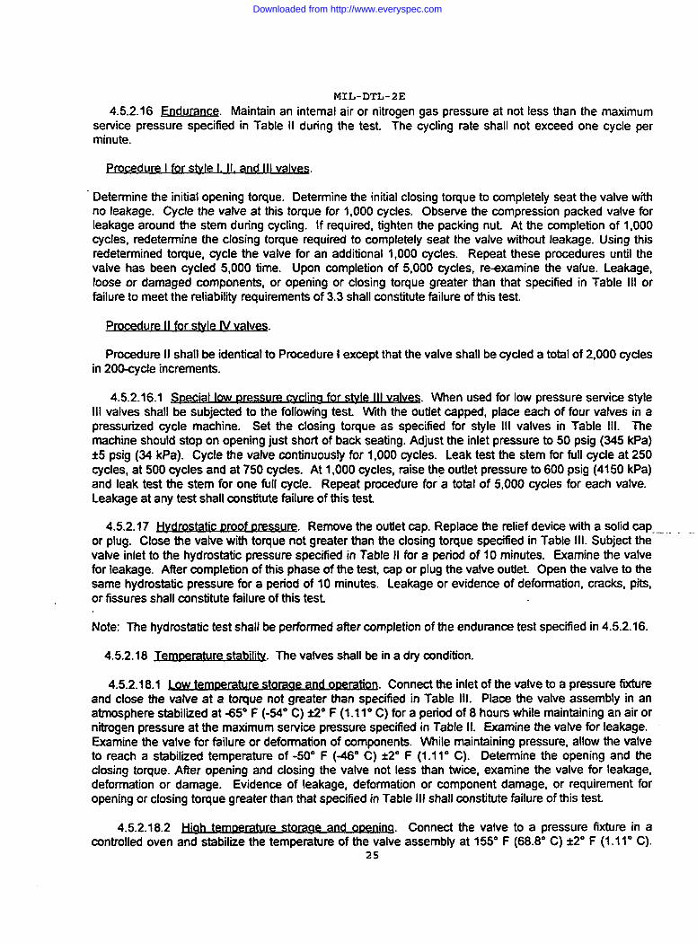
4.5.2.16 Endurance, Maintain an internal air or nitrogen gas pressure at not less than the maximumservice pressure specified in Table II during the test. The cycling rate shall not exceed one cycle perminute.
P- re I for stylu e 1.Il. and IIt valves.
Determine the initial opening torque. Oetermine the initial closing torque to completely seat the valve withno leakage. Cycle the valve at this toque for 1,000 cycles. Obsewe the impression packed valve forleakage around the stem during cycling. If required, tighten the packing nut. At the mmpletion of 1,000cycles, redetermine the closing toque required to completely seat the valve without leakage. Using thisredetermined torque, cycle the valve for an additional 1,000 cycles. Repeat these procedures until thevatve has been cycled 5,000 time. Upon completion of 5,000 cycles, r~xamine the value. Leakage,loose or damaged components, or opening or closing toque greater than that specified in Table Ill orfailure to meet the reliability requirements of 3.3 shall constitute tiilure of this test.
Procedure II shall be identical to Procedure I except that the valve shall be cycled a total of 2,000 cyclesin 200-cycle increments.
4.5.2.16.1 ~pecial @yypressure cycling for style Ill valves. When used for low pressure service styleIll valves shall be subjected to the following test. With the outiet capped, place each of four valves in apressurized cycte machine. Set the closing torque as specified for style Ill valves in Table Ill. Themachine should stop on opening just short of back seating. Adjust the inlet pressure to 50 psig (345 kPa)*5 psig (34 kPa). Cycle the valve continuously for 1,000 cycles. Leak test the stem for full cycle at 250cycles, at 500 cycles and at 750 cycles. At 1,000 cycles, raise th~ outlet pressure to 600 psig (4150 kPa)and leak test the stem for one full cycle. Repeat procedut??for a total of 5,000 cycles for each valve.Leakage at any test shall constitute failure of this test.
4.5.2.17~. Remove the outiet cap. Replace the relief device with a solid capor plug. Close the valve with torque not greater than the closing torque specified in Table Ill. Subject the
. . .. .
valve inlet to the hydrostatic pressure specified in Table II for a period of 10 minutes. Examine the valvefor leakage. After completion of this phase of the test cap or plug the vatve outiet Open the valve to thesame hydrostatic pressure for a period of 10 minutes. Leakage or evidence of deformation, cracks, pits,or fssures shall constitute fdlure of this test.
Note: The hydrostatic test shall be performed after completion of the endurance test specified in 4.5.2.16.
4.5.2.18 ~.. .
The valves shall be in a dfy condition.
4.5.2.18.1 ~. Connect the inlet of the valve to a pressure fixtureand close the valve at a torque not greater than specified in Table Ill. Place the vatve assembly in anatmosphere stabilized at A5° F (-=0 C) i2° F (1.11” C) for a period of 8 hours while maintaining an air ornitrogen pressure at the maximum service prassure specified in Table Il. Examine the valve for leakage.Examine the valve for failure or deformation of components. While maintaining pressure, allow the valveto reach a stabilized temperature of -50° F (46° C) i2° F (1.110 C). Determine the opening and theclosing torque. After opening and closing the vatve not less than twice, examine the valve for leakage,deformation or damage. Evidence of leakage, deformation or component damage, or requirement foropening or closing toque greater than that specitled in Table [11shall constitute failure of this test.
4.5.2.18.2 ~ Connect the vatve to a pressure fixture in amntrolled oven and stabitiie the temperature of the valve assembty at 155° F (68.8° C) t2° F (1.11° C).
25
Downloaded from http://www.everyspec.com

MIL-DTL-2E
Close the valve at a closing torque not greater than specified in Table Ill and pressurize the inlet with air ornitrogen pressure at the maximum service pressure as specified in Table II. Maintain the temperature for8 hours. Examine the valve for leakage, failure or deformation. Allow the valve to cool to temperature of120° F (49° C) &2° F (1.110 C) while maintaining the pressure. Examine the valve for leakage. Open andclose the valve not less than twice and determine the opening and closing torque for the valve. Evidenceof leakage, damage or any component or deformation of the valve, or an opening or closing torque greaterthan specified in Table Ill shall constitute failure of this test.
4.5.2.19 Disassemble inspection. After completion of the tests specified in 4.5.2.12 through 4.5.2.18,disassemble the valve and examine for failures developed during the tests, as specified below.Nonconformance to the applicable requirements paragraph shall constitute failure of this inspection.
Eaw2
Deformation of internal componentsCracked disk insertThread failure or excessive wearDetached componentsCracks, pits, or fissuresGalling of the stemO-ring worn flat, indicating lack of rollingSpindle spring worn flat, indicating slidingagainst body or spindle
RequirementsP=9=P.h3.7.1, 3.7.2,3.7.4, 3.83.3, 3.7.23.33.3,3.7.43.7.13.7.43.9.23.9.4
4.6 lns~ection of gacking.
4.6.1 “Quality conformance inspection of t)ack.
4.6.1.1 Unit of product. For the purpose of inspection, a complete pack prepared for shipment shall beconsidered a unit of product.
4.6.1.2 Sampling. Sampling for inspection and acceptance shall be in accordance with ANSI-21.4.Any departure from a specified requirement shall be classified as a defect. Any defect shall be cause forrejection of the entire lot.
4.6.1.3 Examination. Samples selected in accordance with 4.6.1.2 shall be examined for the followingdefects.
126 Materials, methods and containers not as specified for level A or B. Eachincorrect material, method or container shall constitute one defect.
127 Preservation not as specified for level A.128. Containers not as specified for level A or B.129 Strapping not zinc coated as specified for level A.130 Reinforcing tape and closure not as specified for level B.131 Marking illegible, incorrect, incomplete, or missing.
5. PACKING
5.1 Preservation. Preservation shall be level A or commercial, as specified (see 6.2).
5.1.1 Level A. Each valve shall be presetved in accordance with MlL-P-l 16, method IC-I. Multiplequantities of valves shall be further packed in multiples of 10 or 12 in fiberboard boxes conforming to
26
Downloaded from http://www.everyspec.com

MIL-DTL-2EPPP-B-636, W5cor W6c. The boxes shall beprovid4witi fibetioard dividem toprevent tievalvesfiomcontacting each other.
5.1.2 ~. Commercial preservation shall be in accordance with ASTM D 3951.
5.2 Packing. Packing shall be level A, level B, or commercial, as specified (see 6.2).
5.2.1 Level A. Valves of like description, preserved as specified in 5.1, shall be packed in close-fittingboxes conforming to PPP-B-601, overseas type, style I or J. The boxes shall be closed and strapped inaccordance with the appendix to the box specification.
5.2.2 @vel El. Valves of like description, presetved as specified in 5.1, shall be packed in close-fittingboxes conforming to PPP-B-636, V3C. The boxes shall be ctosed and reinforced as specified in theappendix to the box specification.
5.2.3 ~. Commercial packing shall be in accordance with ASTM D 3951.
5.3 I&@@. In addition to any special marking required by the mntract or purchase order, marking formiliiry levels of protection shall be in accordance with MlL-STD-l 29. Commercial marking shall be inaccordance with ASTM D 3951.
6. NOTES
6.1 Mded usg. The valves covered by this specification in conjunction with applicable detailspecification sheets are intended for installation on compressed or liquefied gas cylinders.
6.2 @iering@ja. Acquisition documents should specify the following:
a.
b.
c.
d.
Titie, number, and date of this specification.
Ttie, number, and date of applicable specification sheet.
Valve type designation (see 1.3).
When a metal outlet cap or plug with chain and retaining ring is requireor when a plastic dust cap is acceptable (see 3.5 and 3.6.1.8).
e. Service pressure required (see 3.7.1.1), (3.6.1.7.6).
f. Cytinder diameter when a dip tube is specified on applicablespecifmation sheet (see 3.6.1.6).
g. When a dip tube assembled to the valve and secured as speciliedis required (see 3.6.1.6).
h. When overall length of vatve other than as specified is acceptable(see 3.10).
i. When marking of vatves other than as specified is required (see3.13.1(C)).
j. When chromium over nickel plated valves are not required formedical application (see 3.12).
27
Downloaded from http://www.everyspec.com
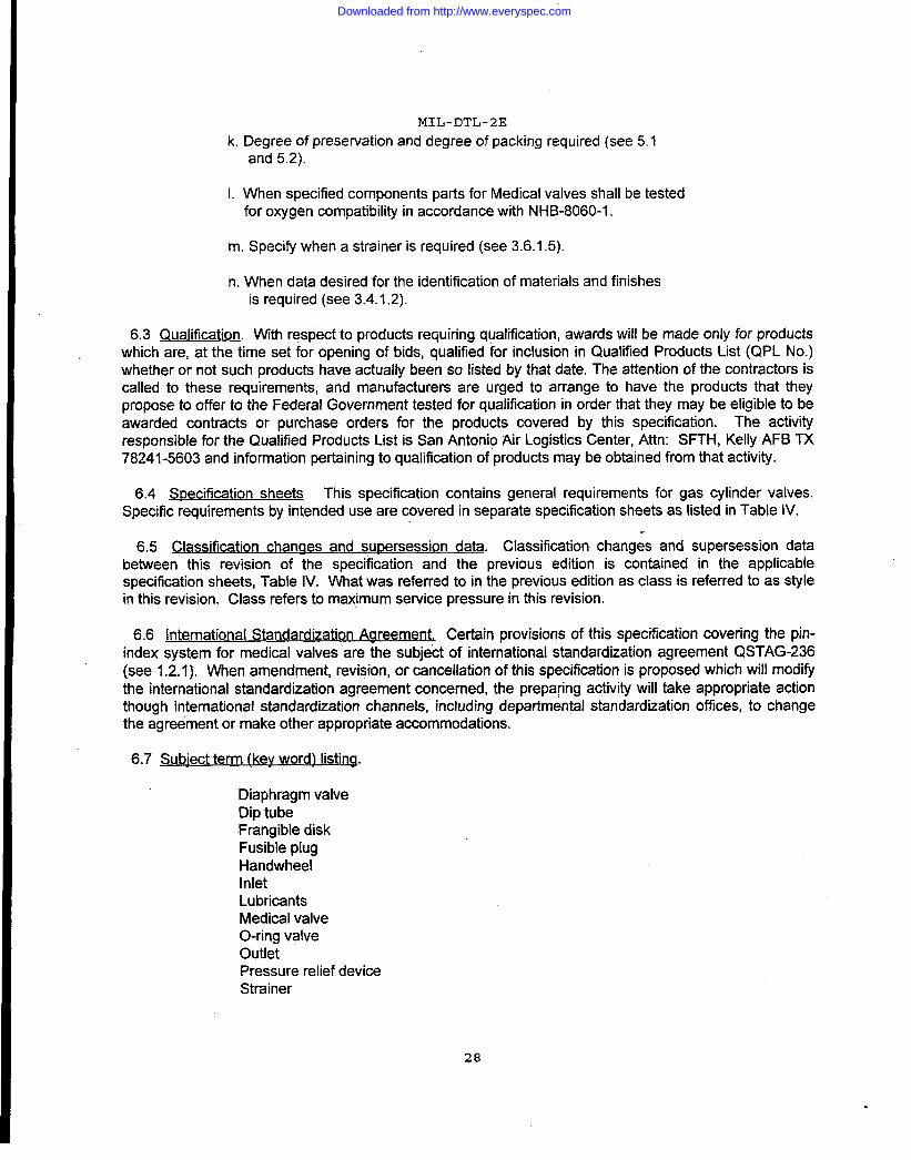
MIL-DTL-2E
k. Degree of preservation and degree of packing required (see 5.1and 5.2).
I 1. When specified components parts for Medical valves shall be testedfor oxygen compatibility in accordance with NHB-8060-1.
I m. Specify when a strainer is required (see 3.6.1.5).
I n. When data desired for the identification of materials and finishesis required (see 3.4.1.2).
6.3 Qualification. With respect to products requiring qualification, awards will be made only for productswhich are, at the time set for opening of bids, qualified for inclusion in Qualified Products List (QPL No.)whether or not such products have actually been so listed by that date. The attention of the contractors iscalled to these requirements, and manufacturers are urged to arrange to have the products that theypropose to offer to the Federal Government tested for qualification in order that they may be eligible to beawarded contracts or purchase orders for the products covered by this specification. The activityresponsible for the Qualified Products List is San Antonio Alr Logistics Center, Attn: SFTH, Kelly AFB TX78241-5603 and information pertaining to qualification of products maybe obtained from that activity.
6.4 Specification sheets This specification contains general requirements for gas cylinder valves.Specific requirements by intended use are covered in separate specification sheets as listed in Table IV.
6.5 Classifi cation chanaes and su~ersession data. Classification changes and supersession databetween this revision of the specification and the previous edition is contained in the applicablespecification sheets, Table IV. What was referred to in the previous edition as class is referred to as stylein this revision. Class refers to maximum service pressure in this revision.
1’6.6 International Standardization Agreement. Certain provisions of this specification covering the pin-
index system for medical valves are the subject of international standardization agreement QSTAG-236(see 1.2.1). When amendment, revision, or cancellation of this specification is proposed which will modifythe international standardization agreement concerned, the prepa@g activity will take appropriate actionthough international standardization channels, including departmental standardization offices, to changethe agreement or make other appropriate accommodations.
I 6.7 Subiect term {kev word) listing.
Diaphragm valveDip tubeFrangible diskFusible plugHandwheelInletLubricantsMedical valveO-ring valveOutletPressure relief deviceStrainer
28
Downloaded from http://www.everyspec.com
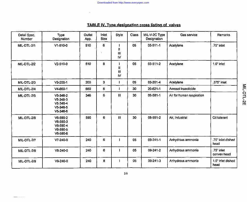
Detail Spec. Type Outlet Inlet Style Class fvllL-V-2C Type Gas service RemarksNumber Designation App, Size Designation
MiL-DTL-2/l V1-510-O 510 6 i 05 03-511-1 Aoetylene .75” inletIiIllIv
MIL-oTL-2/2 V2-51O-O 510 8 I 05 03-511-2 Acetylene 1.0inletIIIllIv
rvllL-DTL-2/3 V3-200-I 200 3 I 05 03-201-4 Acetylene .375” inlet
MIL-oTL-2/4 V4-660-I 660 6’ I 30 20421-1 Aerosol insecticide
MiL-oTL-2/5 W-346-2 346 6 111 30 06-581-1 Air for human respirationV5-346-3W-346-4W-346-5V5-346-6
MIL-DTL-2/6 V6-590-2 590 6 Ill 30 06-591-2 Air, industrial Oil tolerantV6-590-3v&5904V6-590-5V6-590-6
MIL-DTL-217 V7-240-O 240 6 I 05 09-241-1 Anhydrous ammonia ,75” inlet dishedhead
MIL-DTL-2/8 V8-240-O 240 6 I 05 09-241-2 Anhydrous ammonia .75” inletconvex head
MiL-DTL-2/9 V9-240-O 240 8 I 05 09-241-3 Anhydrous ammonia 1.0’ inlet dishedhead
29
Downloaded from http://www.everyspec.com

MIL-DTL-2/l o VI 0-240-0 240 8 I 05 09-2414 Anhydrous ammonia 1.0’ inletconvex head
MIL-DTL-2/l 1 W 1-580-2 580 6 Ill 30 14-581-1 Argon, helium, nitrogen, Inert-oil freeVI 1-580-3 07-581-1 neon, or xenonVI1-5804 05-581-1VI I-580-5 05-581-2VI 1-580-6
MIL-DTL-2/12 superseded
MIL-DTL-2/l 3 superseded
MIL-DTL-2/14 V14-510-1 510 6 II 05 10-511-1 Butane, propane,Iv 08-511-1 butane/propane mixture or
MAPP Gas
MIL-DTL-2/l 5 VI 5-320-3 320 6 Ill 30 02-321-1 Carbon dioxide
VI 5-320-4
MIL-DTL-2/16 V16-320-4 320 6 Ill 30 02-321-2 Carbon dioxide MedicalIv
MIL-DTL-2/17 v-l 7-9404 940 4 1 30 02-941-3 Carbon dioxide Medical/(Pin-”index)
MIL-DTL-2/l 8 VI 8-350-2 350 6 Ill 30 25-351-1 Carbon monoxide
MIL-DTLv-2/l 9 VI 9-350-3 350 6 Ill 30 21-351-1 Ethylene oxide/carbonV19-350-4 dioxide mixtureV19-350-5
MIL-DTL-2/20 V20-820-I 820 6 I 05 13-661-2 Chlorine
MIL-DTL-2/21 V21-820-1 820 6 I 05 13-661+ Chlorine
30
Downloaded from http://www.everyspec.com
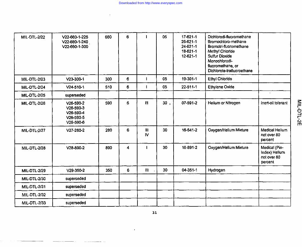
fvllL-DTL-2/22 V22-660-1-225 660 6 I 05 17-621-1 Dichlorodi-fiuoromethaneV22-660-1”240 , 26-621-1 t3romochloro-methaneV224360-I-300 244$21-1 Bromotrt-fluoromethane
18-621-1 Methyl Chloride12%21-1 Sulfur Dioxide
Monochlorodi-fluoromethane, orDichlorote-trafluoroethane
lvllL-DTL-2/23 V23-300-I 300 6 1 05 19-301-1 Ethyl Chloride
MIL-DTLW24 V24-510-1 510 6 I 05 22-511-1 Ethylene Oxide
MIL-DTL4V25 superseded
MIL-DTL-2L26 V26-590-2 590 6 Ill 30 , 07-591-2 Helium or Nitrogen Inert-oil tolerantV26-590-3V26-590-4V26-590-5V26-590~
MIL-DTL-.U7 V27-280-2 280 6 Ill 30 16-541-2 Oxygen/Helium Mixture Medical HeliumIv not over 80
percent
MIL-DTL-2/28 V28-890-2 890 4 I 30 16-891-2 Oxygen/Helium Mixture Medical (Pin-Index) Heliumnot over 80percent
MIL”DTL-m9 V29-350-2 350 6 Ill . 30 04-351-1 Hydrogen
MIL-DTL-2/30 superseded
MIL-DTL”Z31 superseded
MIL-DTL-2/32 superseded
MIL-DTL-2/33 superseded
31
Downloaded from http://www.everyspec.com
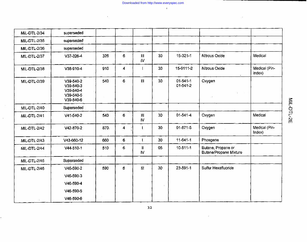
!
MIL-DTL-2/34 superseded
MIL-DTL-2/35 superseded
MIL-DTL-2/36 superseded
MIL-DTL-2/37 V37-326-4 326 6 Ill 30 15-321-1 Nitrous Oxide MedicalIv
MiL-DTL-2/38 V38-910-4 910 4 I 30 15-9111-2 Nitrous Oxide Medical (Pin-index)
MIL-DTL-2/39 V39-540-2 540 6 Ill 30 01-541-1 OxygenV39-540-3 01-541-2V39-5404V39-540-5V39-540-6
MIL-DTL-2/40 Superseded
MIL-DTL-2141 V41-540-2 540 6 Ill 30 01-541-4 Oxygen MedicalIv
MIL-DTL-2/42 V42-870-2 870. 4: I 30 01-871-5 Oxygen Medical(Pin-Index)
MIL-DTL-2/43 V43-660-12 660 6 I 30 11-641-1 Phosgene
MIL-DTL-2/44 V44-510-I 510 6 II 05 10-511-1 Butane, Propane orIv Butane/PropaneMixture
MIL-DTL-2/45 Superseded
MIL-DTL-2/46 V46-590-2 590 6 Ill 30 23-591-1 Sulfur Hexafluoride
V46-590-3
V46-5904
V46-590-5
V46-590-6
32
Downloaded from http://www.everyspec.com

MIL-DTL-2/47 “V47-950-2 950 4 I 30 Air for Human Respiration Medical (Pin-Index)
MIL-DTL-2/48 V48-346-2 346 6 Ill 30 Air for Human Respiration MedicalIv
fwL-DTL-2/49 V49-9204 920 4 I 30 Cyclopropane Medical (Pin-Index)
MIL-oTL”2/50 V50-330-O 330 6 Iv 05 Methyl Bromide .50’ NPT Outlet
MIL-DTL-2/51 V51-677-9 677 6 Ill 75 Argon, Helium, Nitrogen, Inert-oil freeNeon, Xenon or Krypton
MIL-DTL-2/52 V52-660-I-240 660 6 I 05 HaIonV524360-I-300
V52-660-1400
MIL-DTL-2/53 V53-660-3 660 6 Ill 30 HexafluoroethaneV53-6604
V53-660-5
MIL-DTL-2154 V544360-I-225 660 6 I 05 Sulfur DioxideV54-660-I-240V54-660-I-300
MIL-DTL-2/55 V55-540-2 540 4 Ill 30 OxygenV55-540-3V55-540-4V55-540-5 -V55-5404
t
33
Downloaded from http://www.everyspec.com

MIL-DTL-2/56
MIL-DTL-2/57
V56-680-8V56680-10V56-680-11
V57-621-8V57-62I-1OV57-621-I 1
680
621
I MIL-DTL-2/58 V58-677-9 677
=4-==MIL-DTL-2/62 V62-350-2
MIL-DTL-2/63 V63-350-2
MIL-DTL-2/64 V64-330-2
MIL-DTL-2/65 V65-330-2
MIL-DTL-2/66 V66-590-2V66-590-3V66-5904V66-590-5V66-590-6
347
500
930
350
350
330
330
590
6 Ill 55. Argon, Helium, Neon,Nitrogen, Xenon, or Krypton
6 Ill 55 Helium and Nitrogen
8 111 75 Argon, Helium, Neon,Nitrogen, Xenon or Krypton
6 I Ill I 55I
Air for Human Respiration
6 Ill 30 Oxygen/Helium MixtureIv
4 I 30 Oxygen/Helium Mixture
(
6 Ill 30 Methane
6 Ill 30 Natural Gas
6 Ill 30 Hydrogen Chloride
6 Ill 30 Hydrogen Sulfide
6 Ill 30 Mildly oxidizing mixtures
Inefl-oil free
Inert-oil tolerant
Inert-oil free
Medical,Heliumover 80 percent
Medical (Pin-index), Heliumnot over 80percent
5 to 23 percentoxygen
34
Downloaded from http://www.everyspec.com
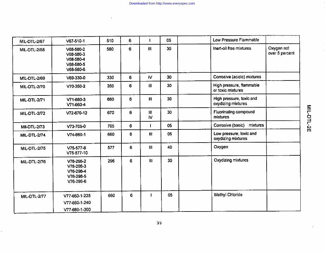
t9
0mCD
omm
MIL-D
TL-2E
omou)
w
om=>
.—
(Dou)U)
0mu)mPJ
In0co0aw
Int-l
Downloaded from http://www.everyspec.com
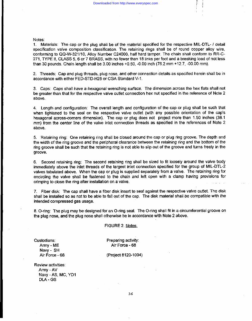
Notes:1. Materials: The cap or the plug shall be of the material specified for the respective MIL-DTL- / detailspecification valve composition classification. The retaining rings shall be of round copper alloy wire,conforming to QQ-W-321 /1O, Alloy Number C24000i half hard temper. The chain shall conform to RR-C-271, TYPE 11,CLASS 5, 6 or 7 BRASS, with no fewer than 18 links per foot and a breaking load of not lessthan 30 pounds. Chain length shall be 3.00 inches +0.50, -0.00 inch (76.2 mm +12.7, -00.00 mm).
2. Threads: Cap and plug threads, plug nose, and other connection details as specified herein shall be inaccordance with either FED-STD-H28 or CGA Standard V-1.
3. Caps: Caps shall have a hexagonal wrenching surface. The dimension across the hex flats shall notbe greater than that for the respective valve outlet connection hex nut specified in the reference of Note 2above.
4. Length and configuration: The overall length and configuration of the cap or plug shall be such thatwhen tightened to the seal on the respective valve outlet (with any possible orientation of the cap’shexagonal across-comers dimension). The cap or plug does not project more than 1.50 inches (38.1mm) from the center line of the valve inlet connection threads as specified in the references of Note 2above.
5. Retainingring:One retaining ring shall be closed around the cap or plug ring groove. The depth andthe width of the ring groove and the peripheral clearance between the retaining ring and the bottom of thering groove shall be such that the retaining ring is not able to slip out of the groove and turns freely in thegroove.
6. Second retaining ring: The second retaining ring shall be sized to fit loosely around the valve bodyimmediately above the inlet threads of the largest inlet connection specified for the group of MIL-DTL-2valves tabulated above. When the cap or plug is supplied separately from a valve. The retaining ring forencircling the valve shall be fastened to the chain and left open with a clamp having provisions forcrimping to close the ring after installation on a valve.
7. Fiber disk The cap shall have a fiber disk insert to seal against the respective valve outlet. The diskshall be installed so as not to be able to fall out of the cap. The disk material shall be compatible with theintended compressed gas usage.
8. O-ring: The plug may be designed for an O-ring seal. The O-ring shall fit in a circumferential groove onthe plug nose, and the plug nose shall othetwise be in accordance with Note 2 above.
FIGURE 2. t40tes.
Custodians:Army - MENavy - SHAir Force -68
Preparing activity:Air Force -68
(Project 8120-1004)
Review activities:Army - AVNavy - AS, MC, YDIDLA - GS
36
Downloaded from http://www.everyspec.com