Embed Size (px)
Citation preview

Juniper Secure Analytics 5800 Hardware Guide
Modified: 2018-01-12
Copyright © 2018, Juniper Networks, Inc.

Juniper Networks, Inc.1133 InnovationWaySunnyvale, California 94089USA408-745-2000www.juniper.net
Juniper Networks, the Juniper Networks logo, Juniper, and Junos are registered trademarks of Juniper Networks, Inc. and/or its affiliates inthe United States and other countries. All other trademarks may be property of their respective owners.
Juniper Networks assumes no responsibility for any inaccuracies in this document. Juniper Networks reserves the right to change, modify,transfer, or otherwise revise this publication without notice.
Juniper Secure Analytics 5800 Hardware GuideCopyright © 2018 Juniper Networks, Inc. All rights reserved.
The information in this document is current as of the date on the title page.
YEAR 2000 NOTICE
Juniper Networks hardware and software products are Year 2000 compliant. Junos OS has no known time-related limitations through theyear 2038. However, the NTP application is known to have some difficulty in the year 2036.
ENDUSER LICENSE AGREEMENT
The Juniper Networks product that is the subject of this technical documentation consists of (or is intended for use with) Juniper Networkssoftware. Use of such software is subject to the terms and conditions of the End User License Agreement (“EULA”) posted athttp://www.juniper.net/support/eula/. By downloading, installing or using such software, you agree to the terms and conditions of thatEULA.
Copyright © 2018, Juniper Networks, Inc.ii

Table of Contents
About the Documentation . . . . . . . . . . . . . . . . . . . . . . . . . . . . . . . . . . . . . . . . . . . . xi
Documentation and Release Notes . . . . . . . . . . . . . . . . . . . . . . . . . . . . . . . . . . xi
Documentation Conventions . . . . . . . . . . . . . . . . . . . . . . . . . . . . . . . . . . . . . . . xi
Documentation Feedback . . . . . . . . . . . . . . . . . . . . . . . . . . . . . . . . . . . . . . . . xiii
Requesting Technical Support . . . . . . . . . . . . . . . . . . . . . . . . . . . . . . . . . . . . . xiv
Self-Help Online Tools and Resources . . . . . . . . . . . . . . . . . . . . . . . . . . . xiv
Opening a Case with JTAC . . . . . . . . . . . . . . . . . . . . . . . . . . . . . . . . . . . . . xiv
Chapter 1 Overview . . . . . . . . . . . . . . . . . . . . . . . . . . . . . . . . . . . . . . . . . . . . . . . . . . . . . . . . . 17
JSA5800 System Overview . . . . . . . . . . . . . . . . . . . . . . . . . . . . . . . . . . . . . . . . . . . 17
JSA5800 Appliance Description . . . . . . . . . . . . . . . . . . . . . . . . . . . . . . . . . . . . 17
JSA5800 Appliance Transceiver Interface . . . . . . . . . . . . . . . . . . . . . . . . . . . . 18
Field-Replaceable Units on the JSA5800 Appliance . . . . . . . . . . . . . . . . . . . . 18
JSA5800 Chassis . . . . . . . . . . . . . . . . . . . . . . . . . . . . . . . . . . . . . . . . . . . . . . . . . . . 19
JSA5800 Appliance Front Panel Description . . . . . . . . . . . . . . . . . . . . . . . . . . 19
JSA5800 Appliance Back Panel Description . . . . . . . . . . . . . . . . . . . . . . . . . . 21
Chapter 2 Site Planning, Preparation, and Specifications . . . . . . . . . . . . . . . . . . . . . . . . 25
JSA5800 Site Guidelines and Requirements . . . . . . . . . . . . . . . . . . . . . . . . . . . . . 25
General Site Installation Guidelines for the JSA5800 Appliance . . . . . . . . . . 25
JSA5800 Appliance Physical Specifications . . . . . . . . . . . . . . . . . . . . . . . . . . 26
JSA5800 Appliance Rack Requirements . . . . . . . . . . . . . . . . . . . . . . . . . . . . . 27
Additional Hardware Requirements . . . . . . . . . . . . . . . . . . . . . . . . . . . . . . . . . 28
Chapter 3 Initial Installation and Configuration . . . . . . . . . . . . . . . . . . . . . . . . . . . . . . . . . 31
JSA5800 Installation Overview . . . . . . . . . . . . . . . . . . . . . . . . . . . . . . . . . . . . . . . . 31
Overview of Installing the JSA5800 Appliance in a Rack . . . . . . . . . . . . . . . . 31
Tools and Parts Required for Installing the JSA5800 Appliance . . . . . . . . . . . 31
Installing the JSA5800 in a Rack . . . . . . . . . . . . . . . . . . . . . . . . . . . . . . . . . . . . . . . 32
Installing the JSA5800 Appliance . . . . . . . . . . . . . . . . . . . . . . . . . . . . . . . . . . 32
Installing the JSA5800 Appliance Using Front-and-Rear-Mounting Flush
to a Rack . . . . . . . . . . . . . . . . . . . . . . . . . . . . . . . . . . . . . . . . . . . . . . . . . . 34
Connecting the JSA5800 to Power . . . . . . . . . . . . . . . . . . . . . . . . . . . . . . . . . . . . . 39
Connecting the JSA5800 Appliance to Ground . . . . . . . . . . . . . . . . . . . . . . . 39
Connecting the JSA5800 Appliance to a DC Power Source . . . . . . . . . . . . . . 39
Connecting the JSA5800 Appliance to a Management Device . . . . . . . . . . . . . . . 40
Configuring the JSA5800 . . . . . . . . . . . . . . . . . . . . . . . . . . . . . . . . . . . . . . . . . . . . . 42
Configuring Basic Settings on the JSA5800 Appliance . . . . . . . . . . . . . . . . . . 42
Accessing the JSA Interface . . . . . . . . . . . . . . . . . . . . . . . . . . . . . . . . . . . . . . . 44
iiiCopyright © 2018, Juniper Networks, Inc.

Chapter 4 Maintaining Components . . . . . . . . . . . . . . . . . . . . . . . . . . . . . . . . . . . . . . . . . . 47
Maintaining the JSA5800 RAID Array . . . . . . . . . . . . . . . . . . . . . . . . . . . . . . . . . . . 47
Maintaining JSA5800 Power System . . . . . . . . . . . . . . . . . . . . . . . . . . . . . . . . . . . 48
Maintaining the JSA5800 Power Supply . . . . . . . . . . . . . . . . . . . . . . . . . . . . . 48
Replacing an AC Power Supply on the JSA5800 Appliance . . . . . . . . . . . . . . 49
Replacing AC Power Supply Cables on the JSA5800 Appliance . . . . . . . . . . 49
Replacing a DC Power Supply on the JSA5800 Appliance . . . . . . . . . . . . . . . 50
Replacing DC Power Supply Cables on the JSA5800 Appliance . . . . . . . . . . . 51
Chapter 5 Troubleshooting Hardware . . . . . . . . . . . . . . . . . . . . . . . . . . . . . . . . . . . . . . . . . 53
Contacting Juniper Networks Technical Assistance Center . . . . . . . . . . . . . . . . . . 53
Chapter 6 Safety and Compliance Information . . . . . . . . . . . . . . . . . . . . . . . . . . . . . . . . . 55
Definitions of Safety Warning Levels . . . . . . . . . . . . . . . . . . . . . . . . . . . . . . . . . . . . 56
General Safety Guidelines and Warnings . . . . . . . . . . . . . . . . . . . . . . . . . . . . . . . . 57
Restricted Access Warning . . . . . . . . . . . . . . . . . . . . . . . . . . . . . . . . . . . . . . . . . . . 58
Qualified Personnel Warning . . . . . . . . . . . . . . . . . . . . . . . . . . . . . . . . . . . . . . . . . 60
Prevention of Electrostatic Discharge Damage . . . . . . . . . . . . . . . . . . . . . . . . . . . . 61
Warning Statement for Norway and Sweden . . . . . . . . . . . . . . . . . . . . . . . . . . . . . 62
Fire Safety Requirements . . . . . . . . . . . . . . . . . . . . . . . . . . . . . . . . . . . . . . . . . . . . . 62
Fire Suppression . . . . . . . . . . . . . . . . . . . . . . . . . . . . . . . . . . . . . . . . . . . . . . . . 63
Fire Suppression Equipment . . . . . . . . . . . . . . . . . . . . . . . . . . . . . . . . . . . . . . 63
Installation Instructions Warning . . . . . . . . . . . . . . . . . . . . . . . . . . . . . . . . . . . . . . 63
Chassis Lifting Guidelines for the JSA5800 Appliance . . . . . . . . . . . . . . . . . . . . . 64
Ramp Warning . . . . . . . . . . . . . . . . . . . . . . . . . . . . . . . . . . . . . . . . . . . . . . . . . . . . . 65
Rack-Mounting and Cabinet-Mounting Warnings . . . . . . . . . . . . . . . . . . . . . . . . . 65
Grounded Equipment Warning . . . . . . . . . . . . . . . . . . . . . . . . . . . . . . . . . . . . . . . . 69
Laser and LED Safety Guidelines and Warnings . . . . . . . . . . . . . . . . . . . . . . . . . . . 70
General Laser Safety Guidelines . . . . . . . . . . . . . . . . . . . . . . . . . . . . . . . . . . . 70
Class 1 Laser Product Warning . . . . . . . . . . . . . . . . . . . . . . . . . . . . . . . . . . . . . 70
Class 1 LED Product Warning . . . . . . . . . . . . . . . . . . . . . . . . . . . . . . . . . . . . . . . 71
Laser Beam Warning . . . . . . . . . . . . . . . . . . . . . . . . . . . . . . . . . . . . . . . . . . . . . 71
Radiation from Open Port Apertures Warning . . . . . . . . . . . . . . . . . . . . . . . . . . . . 72
Maintenance and Operational Safety Guidelines and Warnings . . . . . . . . . . . . . . 73
Battery Handling Warning . . . . . . . . . . . . . . . . . . . . . . . . . . . . . . . . . . . . . . . . . 73
Jewelry Removal Warning . . . . . . . . . . . . . . . . . . . . . . . . . . . . . . . . . . . . . . . . . 74
Lightning Activity Warning . . . . . . . . . . . . . . . . . . . . . . . . . . . . . . . . . . . . . . . . 76
Operating Temperature Warning . . . . . . . . . . . . . . . . . . . . . . . . . . . . . . . . . . . 76
Product Disposal Warning . . . . . . . . . . . . . . . . . . . . . . . . . . . . . . . . . . . . . . . . 78
Action to Take After an Electrical Accident . . . . . . . . . . . . . . . . . . . . . . . . . . . . . . . 79
General Electrical Safety Guidelines and Warnings . . . . . . . . . . . . . . . . . . . . . . . . 79
AC Power Electrical Safety Guidelines . . . . . . . . . . . . . . . . . . . . . . . . . . . . . . . . . . 80
AC Power Disconnection Warning . . . . . . . . . . . . . . . . . . . . . . . . . . . . . . . . . . . . . . 81
DC Power Electrical Safety Guidelines . . . . . . . . . . . . . . . . . . . . . . . . . . . . . . . . . . 83
DC Power Disconnection Warning . . . . . . . . . . . . . . . . . . . . . . . . . . . . . . . . . . . . . 84
DC Power Grounding Requirements and Warning . . . . . . . . . . . . . . . . . . . . . . . . . 85
DC Power Wiring Sequence Warning . . . . . . . . . . . . . . . . . . . . . . . . . . . . . . . . . . . 86
Multiple Power Supplies Disconnection Warning . . . . . . . . . . . . . . . . . . . . . . . . . . 88
Copyright © 2018, Juniper Networks, Inc.iv
Juniper Secure Analytics 5800 Hardware Guide

TN Power Warning . . . . . . . . . . . . . . . . . . . . . . . . . . . . . . . . . . . . . . . . . . . . . . . . . . 89
Agency Approvals for the JSA5800 Appliance . . . . . . . . . . . . . . . . . . . . . . . . . . . 89
Compliance Statements for EMC Requirements for the JSA5800 Appliance . . . 90
Canada . . . . . . . . . . . . . . . . . . . . . . . . . . . . . . . . . . . . . . . . . . . . . . . . . . . . . . . 90
European Community . . . . . . . . . . . . . . . . . . . . . . . . . . . . . . . . . . . . . . . . . . . . 91
Japan . . . . . . . . . . . . . . . . . . . . . . . . . . . . . . . . . . . . . . . . . . . . . . . . . . . . . . . . . 91
Korea . . . . . . . . . . . . . . . . . . . . . . . . . . . . . . . . . . . . . . . . . . . . . . . . . . . . . . . . . 92
United States . . . . . . . . . . . . . . . . . . . . . . . . . . . . . . . . . . . . . . . . . . . . . . . . . . 92
FCC Part 15 Statement . . . . . . . . . . . . . . . . . . . . . . . . . . . . . . . . . . . . . . . . . . . 92
Compliance Statements for Acoustic Noise for the JSA5800 Appliance . . . . . . . 93
vCopyright © 2018, Juniper Networks, Inc.
Table of Contents

Copyright © 2018, Juniper Networks, Inc.vi
Juniper Secure Analytics 5800 Hardware Guide

List of Figures
Chapter 1 Overview . . . . . . . . . . . . . . . . . . . . . . . . . . . . . . . . . . . . . . . . . . . . . . . . . . . . . . . . . 17
Figure 1: JSA5800 Front Panel . . . . . . . . . . . . . . . . . . . . . . . . . . . . . . . . . . . . . . . . . 19
Figure 2: JSA5800 Front Panel LEDs . . . . . . . . . . . . . . . . . . . . . . . . . . . . . . . . . . . . 20
Figure 3: JSA5800 Back Panel . . . . . . . . . . . . . . . . . . . . . . . . . . . . . . . . . . . . . . . . . 21
Figure 4: JSA5800 Ethernet Port LEDs . . . . . . . . . . . . . . . . . . . . . . . . . . . . . . . . . . 22
Chapter 3 Initial Installation and Configuration . . . . . . . . . . . . . . . . . . . . . . . . . . . . . . . . . 31
Figure 5: Connecting the AC Power Cord . . . . . . . . . . . . . . . . . . . . . . . . . . . . . . . . . 33
Figure 6: LEDs on the JSA5800 . . . . . . . . . . . . . . . . . . . . . . . . . . . . . . . . . . . . . . . . 33
Figure 7: Identifying the Inner, Middle, and Outer Rails . . . . . . . . . . . . . . . . . . . . . . 35
Figure 8: Sliding and Detaching the Inner Rails . . . . . . . . . . . . . . . . . . . . . . . . . . . . 36
Figure 9: Installing the Inner Rails . . . . . . . . . . . . . . . . . . . . . . . . . . . . . . . . . . . . . . 36
Figure 10: Inserting the Front Mounting Rails . . . . . . . . . . . . . . . . . . . . . . . . . . . . . . 37
Figure 11: Inserting the Front and Rear Mounting Rails . . . . . . . . . . . . . . . . . . . . . . 37
Figure 12: Aligning the Chassis Rails with the Ball-Bearing Shuttle . . . . . . . . . . . . 38
Figure 13: Installing the Chassis in a Four-Post Rack . . . . . . . . . . . . . . . . . . . . . . . 38
Figure 14: Connecting the Management Device . . . . . . . . . . . . . . . . . . . . . . . . . . . . 41
Chapter 6 Safety and Compliance Information . . . . . . . . . . . . . . . . . . . . . . . . . . . . . . . . . 55
Figure 15: Placing a Component into an Antistatic Bag . . . . . . . . . . . . . . . . . . . . . 62
viiCopyright © 2018, Juniper Networks, Inc.

Copyright © 2018, Juniper Networks, Inc.viii
Juniper Secure Analytics 5800 Hardware Guide

List of Tables
About the Documentation . . . . . . . . . . . . . . . . . . . . . . . . . . . . . . . . . . . . . . . . . . xi
Table 1: Notice Icons . . . . . . . . . . . . . . . . . . . . . . . . . . . . . . . . . . . . . . . . . . . . . . . . . xii
Table 2: Text and Syntax Conventions . . . . . . . . . . . . . . . . . . . . . . . . . . . . . . . . . . . xii
Chapter 1 Overview . . . . . . . . . . . . . . . . . . . . . . . . . . . . . . . . . . . . . . . . . . . . . . . . . . . . . . . . . 17
Table 3: JSA5800 Appliance Transceiver Interface Types . . . . . . . . . . . . . . . . . . . 18
Table 4: JSA5800 Front Panel Components . . . . . . . . . . . . . . . . . . . . . . . . . . . . . . 19
Table 5: JSA5800 Front Panel LEDs . . . . . . . . . . . . . . . . . . . . . . . . . . . . . . . . . . . . 20
Table 6: JSA5800 Back Panel Components . . . . . . . . . . . . . . . . . . . . . . . . . . . . . . 22
Table 7: JSA5800 Ethernet Port LEDs . . . . . . . . . . . . . . . . . . . . . . . . . . . . . . . . . . . 23
Chapter 2 Site Planning, Preparation, and Specifications . . . . . . . . . . . . . . . . . . . . . . . . 25
Table 8: JSA5800 Appliance Physical Specifications . . . . . . . . . . . . . . . . . . . . . . 26
Table 9: Rack Requirements for the JSA5800 Appliance . . . . . . . . . . . . . . . . . . . . 27
Table 10: Required JSA Ports . . . . . . . . . . . . . . . . . . . . . . . . . . . . . . . . . . . . . . . . . . 28
Chapter 3 Initial Installation and Configuration . . . . . . . . . . . . . . . . . . . . . . . . . . . . . . . . . 31
Table 11: Required Tools and Parts for Installing the JSA5800 Appliance . . . . . . . 31
Table 12: DB-9 Console Connector Pinouts for the JSA5800 Appliance . . . . . . . . 34
ixCopyright © 2018, Juniper Networks, Inc.
Copyright © 2018, Juniper Networks, Inc.x
Juniper Secure Analytics 5800 Hardware Guide
About the Documentation
• Documentation and Release Notes on page xi
• Documentation Conventions on page xi
• Documentation Feedback on page xiii
• Requesting Technical Support on page xiv
Documentation and Release Notes
To obtain the most current version of all Juniper Networks®technical documentation,
see the product documentation page on the Juniper Networks website at
http://www.juniper.net/techpubs/.
If the information in the latest release notes differs from the information in the
documentation, follow the product Release Notes.
Juniper Networks Books publishes books by Juniper Networks engineers and subject
matter experts. These books go beyond the technical documentation to explore the
nuances of network architecture, deployment, and administration. The current list can
be viewed at http://www.juniper.net/books.
Documentation Conventions
Table 1 on page xii defines notice icons used in this guide.
xiCopyright © 2018, Juniper Networks, Inc.

Table 1: Notice Icons
DescriptionMeaningIcon
Indicates important features or instructions.Informational note
Indicates a situation that might result in loss of data or hardware damage.Caution
Alerts you to the risk of personal injury or death.Warning
Alerts you to the risk of personal injury from a laser.Laser warning
Indicates helpful information.Tip
Alerts you to a recommended use or implementation.Best practice
Table 2 on page xii defines the text and syntax conventions used in this guide.
Table 2: Text and Syntax Conventions
ExamplesDescriptionConvention
To enter configuration mode, type theconfigure command:
user@host> configure
Represents text that you type.Bold text like this
user@host> show chassis alarms
No alarms currently active
Represents output that appears on theterminal screen.
Fixed-width text like this
• A policy term is a named structurethat defines match conditions andactions.
• Junos OS CLI User Guide
• RFC 1997,BGPCommunities Attribute
• Introduces or emphasizes importantnew terms.
• Identifies guide names.
• Identifies RFC and Internet draft titles.
Italic text like this
Configure themachine’s domain name:
[edit]root@# set system domain-namedomain-name
Represents variables (options for whichyou substitute a value) in commands orconfiguration statements.
Italic text like this
Copyright © 2018, Juniper Networks, Inc.xii
Juniper Secure Analytics 5800 Hardware Guide

Table 2: Text and Syntax Conventions (continued)
ExamplesDescriptionConvention
• To configure a stub area, include thestub statement at the [edit protocolsospf area area-id] hierarchy level.
• Theconsoleport is labeledCONSOLE.
Represents names of configurationstatements, commands, files, anddirectories; configurationhierarchy levels;or labels on routing platformcomponents.
Text like this
stub <default-metricmetric>;Encloses optional keywords or variables.< > (angle brackets)
broadcast | multicast
(string1 | string2 | string3)
Indicates a choice between themutuallyexclusive keywords or variables on eitherside of the symbol. The set of choices isoften enclosed in parentheses for clarity.
| (pipe symbol)
rsvp { # Required for dynamicMPLS onlyIndicates a comment specified on thesame lineas theconfiguration statementto which it applies.
# (pound sign)
community namemembers [community-ids ]
Encloses a variable for which you cansubstitute one or more values.
[ ] (square brackets)
[edit]routing-options {static {route default {nexthop address;retain;
}}
}
Identifies a level in the configurationhierarchy.
Indention and braces ( { } )
Identifies a leaf statement at aconfiguration hierarchy level.
; (semicolon)
GUI Conventions
• In the Logical Interfaces box, selectAll Interfaces.
• To cancel the configuration, clickCancel.
Representsgraphicaluser interface(GUI)items you click or select.
Bold text like this
In the configuration editor hierarchy,select Protocols>Ospf.
Separates levels in a hierarchy of menuselections.
> (bold right angle bracket)
Documentation Feedback
We encourage you to provide feedback, comments, and suggestions so that we can
improve the documentation. You can provide feedback by using either of the following
methods:
• Online feedback rating system—On any page of the Juniper Networks TechLibrary site
athttp://www.juniper.net/techpubs/index.html, simply click the stars to rate thecontent,
and use the pop-up form to provide us with information about your experience.
Alternately, you can use the online feedback form at
http://www.juniper.net/techpubs/feedback/.
xiiiCopyright © 2018, Juniper Networks, Inc.
About the Documentation

• E-mail—Sendyourcommentsto [email protected]. Includethedocument
or topic name, URL or page number, and software version (if applicable).
Requesting Technical Support
Technical product support is available through the JuniperNetworksTechnicalAssistance
Center (JTAC). If you are a customer with an active J-Care or Partner Support Service
support contract, or are covered under warranty, and need post-sales technical support,
you can access our tools and resources online or open a case with JTAC.
• JTAC policies—For a complete understanding of our JTAC procedures and policies,
review the JTAC User Guide located at
http://www.juniper.net/us/en/local/pdf/resource-guides/7100059-en.pdf.
• Product warranties—For product warranty information, visit
http://www.juniper.net/support/warranty/.
• JTAC hours of operation—The JTAC centers have resources available 24 hours a day,
7 days a week, 365 days a year.
Self-Help Online Tools and Resources
For quick and easy problem resolution, Juniper Networks has designed an online
self-service portal called the Customer Support Center (CSC) that provides youwith the
following features:
• Find CSC offerings: http://www.juniper.net/customers/support/
• Search for known bugs: https://prsearch.juniper.net/
• Find product documentation: http://www.juniper.net/documentation/
• Find solutions and answer questions using our Knowledge Base: http://kb.juniper.net/
• Download the latest versions of software and review release notes:
http://www.juniper.net/customers/csc/software/
• Search technical bulletins for relevant hardware and software notifications:
http://kb.juniper.net/InfoCenter/
• Join and participate in the Juniper Networks Community Forum:
http://www.juniper.net/company/communities/
• Open a case online in the CSC Case Management tool: http://www.juniper.net/cm/
Toverify serviceentitlementbyproduct serial number, useourSerialNumberEntitlement
(SNE) Tool: https://entitlementsearch.juniper.net/entitlementsearch/
Opening a Casewith JTAC
You can open a case with JTAC on theWeb or by telephone.
• Use the Case Management tool in the CSC at http://www.juniper.net/cm/.
• Call 1-888-314-JTAC (1-888-314-5822 toll-free in the USA, Canada, and Mexico).
Copyright © 2018, Juniper Networks, Inc.xiv
Juniper Secure Analytics 5800 Hardware Guide

For international or direct-dial options in countries without toll-free numbers, see
http://www.juniper.net/support/requesting-support.html.
xvCopyright © 2018, Juniper Networks, Inc.
About the Documentation
Copyright © 2018, Juniper Networks, Inc.xvi
Juniper Secure Analytics 5800 Hardware Guide

CHAPTER 1
Overview
• JSA5800 SystemOverview on page 17
• JSA5800 Chassis on page 19
JSA5800 SystemOverview
• JSA5800 Appliance Description on page 17
• JSA5800 Appliance Transceiver Interface on page 18
• Field-Replaceable Units on the JSA5800 Appliance on page 18
JSA5800 Appliance Description
The JuniperSecureAnalytics5800(JSA5800) isanenterpriseandcarrier-classappliance
that provides a scalable network security management solution for medium-sized
companies up to large global organizations.
The JSA5800 appliance is a 2-U, rack-mountable chassis with AC power supplies (or
optional DC power supplies), eight hot-swappable hard drives, 128GBmemory, and two
10 Gigabit and four Gigabit Ethernet interfaces.
The JSA5800 appliance:
• Responds to the right threats at the right time through effective analysis of networks,
events, and audit log files.
• Identifies environmental anomalies in the network, an attack path, and the source of
a threat.
• Provides network remediation for threat responses across all security products.
The JSA5800 appliance provides the following features:
• Monitor utility for power supply unit (PSU) and fans
• Add setup logs automatically
• Support high availability (HA)
• Hot-swappable hard disk supporting RAID
17Copyright © 2018, Juniper Networks, Inc.

• Automatic RAID rebuild on HDD swap
• Supporthot-swappabledual-AC(oroptionaldual-DCpowersupplies)witha redundant
configuration in the chassis
The JSA5800 appliances use the following drivers for security analysis of external and
internal threats:
• Security InformationManagement (SIM)—SIMprovides reporting and analysis of data
from host systems, applications, and security devices to support security policy
compliancemanagement, internal threat management, and regulatory compliance
initiatives.
• Security Event Management (SEM)—SEM improves security incident response
capabilities by processing data from security devices and network devices. It helps
network administrators to provide effective responses to external and internal threats.
See Also General Site Installation Guidelines for the JSA5800 Appliance on page 25•
• JSA5800 Installation Overview on page 31
JSA5800 Appliance Transceiver Interface
Table 3 on page 18 lists the different types of transceiver interfaces available on the
JSA5800 appliance.
Table 3: JSA5800 Appliance Transceiver Interface Types
DescriptionCard ModelTransceiver Type
Dual Rate 10GBASE-LR/1000BASE-LXUNIV-SFPP-DUAL-SRSFP+
Dual Rate 10GBASE-SR/1000BASE-SXUNIV-SFPP-DUAL-LR
See Also JSA5800 Appliance Description on page 17•
• JSA5800 Appliance Physical Specifications on page 26
• JSA5800 Appliance Back Panel Description on page 21
Field-Replaceable Units on the JSA5800 Appliance
Field-replaceable units (FRUs) are hardware components that can be replaced at the
customersite.Hot-swappableFRUsare thecomponents that youcan removeand replace
without powering off the device or disrupting the functions of the device.
FRUs supported by the JSA5800 appliance includes the power supply and RAID array.
See Also Replacing AC Power Supply Cables on the JSA5800 Appliance on page 49•
• Replacing an AC Power Supply on the JSA5800 Appliance on page 49
Copyright © 2018, Juniper Networks, Inc.18
Juniper Secure Analytics 5800 Hardware Guide

• Replacing a DC Power Supply on the JSA5800 Appliance on page 50
• Replacing DC Power Supply Cables on the JSA5800 Appliance on page 51
RelatedDocumentation
JSA5800 Chassis on page 19•
• JSA5800 Site Guidelines and Requirements on page 25
• JSA5800 Installation Overview on page 31
• Configuring the JSA5800 on page 42
JSA5800 Chassis
• JSA5800 Appliance Front Panel Description on page 19
• JSA5800 Appliance Back Panel Description on page 21
JSA5800 Appliance Front Panel Description
Figure 1 on page 19 shows the front panel components of the JSA5800 appliance.
Figure 1: JSA5800 Front Panel
Table 4 on page 19 lists the front panel components of the JSA5800 appliance.
Table 4: JSA5800 Front Panel Components
DescriptionComponentCallout
Protects the appliance.Front Bezel1
Locks the appliance.Lock2
19Copyright © 2018, Juniper Networks, Inc.
Chapter 1: Overview

Table 4: JSA5800 Front Panel Components (continued)
DescriptionComponentCallout
Powers on or powers off theappliance.
Power button3
Eight 900 GB hard disk drives(Drive0 - Drive7).
Hard drive4
Empty slots (Drive8 - Drive15).Hard drive5
Reboots the appliance.RESET button6
Provides thecolorsandstates, andthe status they indicate.
Chassis LEDs7
Figure 2 on page 20 shows the front panel LEDs of the JSA5800 appliance.
Figure 2: JSA5800 Front Panel LEDsg000632
1
2
3
4
5
6
Table 5 on page 20 lists the front panel LEDs of the JSA5800 appliance.
Table 5: JSA5800 Front Panel LEDs
DescriptionLEDsCallout
Solid green—Indicates that theappliance is receiving power.
Power1
When blinking, it indicatesDataShare interface activity.
LAN22
Red—Indicates a power supplyfailure.
Amber—Indicates that theappliance is operating normally.The LEDmight glow amber if arescueconfiguration isnot set. Thisis not a panic condition.
Alert/Power fail3
Copyright © 2018, Juniper Networks, Inc.20
Juniper Secure Analytics 5800 Hardware Guide

Table 5: JSA5800 Front Panel LEDs (continued)
DescriptionLEDsCallout
Unused.Hard drive4
When blinking, it indicatesManagement interface activity.
LAN15
• Red (blinking)—Indicates a fanfailure.
• Solid red—Indicatesanoverheatcondition, which might becaused by cables obstructingthe airflow in the system or theambient room temperaturebeing too warm.
You can perform the followingchecks:
• Check the routing of thecables and ensure that allfans are present andoperating normally.
• Ensure that the chassiscovers are installed.
• Verify that the heatsinks areinstalled properly.
• Red(slowlyblinking)—Indicatesa power failure.
• Solid blue —Indicates UIDfunction is activated.
Information6
See Also JSA5800 Appliance Description on page 17•
• JSA5800 Appliance Back Panel Description on page 21
JSA5800 Appliance Back Panel Description
Figure 3 on page 21 shows the back panel components of the JSA5800 appliance.
Figure 3: JSA5800 Back Panel
21Copyright © 2018, Juniper Networks, Inc.
Chapter 1: Overview

Table 6 on page 22 lists the back panel components of the JSA5800 appliance.
Table 6: JSA5800 Back Panel Components
DescriptionComponentsCallout
Provides power to all components.Power supply1
1 RJ-45 dedicated IPMI LAN port.Dedicated IPMI LAN port2
4RJ-45Gigabit Ethernet LANports.
Top left: eth4; top right: eth5
Bottom left: eth2; bottomright: eth3
NOTE: You can choose any GBports as the management port.
GB ports3
2 SFP+ 10GbE LAN ports. The topport is eth0 and the bottom port iseth1.
10 GB+SFP ports4
1 VGA port.
NOTE: This port is not supported.
VGA port5
4 USB ports.
Top left: port 1; top right: port 3
Bottom left: port 0; bottom right:port 2
USB ports6
1 DB-9 COM port.COM port7
Figure 4 on page 22 shows the back panel Ethernet port LEDs of the JSA5800appliance.
Figure 4: JSA5800 Ethernet Port LEDs
Table 7 on page 23 lists the JSA5800 Ethernet port LEDs.
Copyright © 2018, Juniper Networks, Inc.22
Juniper Secure Analytics 5800 Hardware Guide

Table 7: JSA5800 Ethernet Port LEDs
DescriptionLEDsCallout
• Off—Indicates no connection or thespeed of the connection is 10 Mbps.
• Green—Indicates that the speed ofthe connection is 100 Mbps.
• Amber—Indicates that the speed ofthe connection is 1 Gbps.
Link1
Indicates link activity.Activity2
See Also JSA5800 Appliance Description on page 17•
• JSA5800 Appliance Front Panel Description on page 19
RelatedDocumentation
• JSA5800 Installation Overview on page 31
• JSA5800 SystemOverview on page 17
23Copyright © 2018, Juniper Networks, Inc.
Chapter 1: Overview

Copyright © 2018, Juniper Networks, Inc.24
Juniper Secure Analytics 5800 Hardware Guide

CHAPTER 2
Site Planning, Preparation, andSpecifications
• JSA5800 Site Guidelines and Requirements on page 25
JSA5800 Site Guidelines and Requirements
• General Site Installation Guidelines for the JSA5800 Appliance on page 25
• JSA5800 Appliance Physical Specifications on page 26
• JSA5800 Appliance Rack Requirements on page 27
• Additional Hardware Requirements on page 28
General Site Installation Guidelines for the JSA5800 Appliance
The following precautions can help you plan an acceptable operating environment for
your JSA5800 appliance and avoid environmentally caused equipment failures:
• For the cooling system to function properly, the airflow around the chassis must be
unrestricted. Allow sufficient clearance between the front and back of the chassis and
adjacentequipment. Ensure that there isadequatecirculation in the installation location.
• Followtheelectrostaticdischarge (ESD)procedures toavoiddamaging theequipment.
Static discharge can cause components to fail, either completely or intermittently over
time.
NOTE: Install the appliance only in restricted areas, such as dedicatedequipment roomsandequipmentclosets, inaccordancewithArticles 110–16,110–17, and 110–18 of the National Electrical Code, ANSI/NFPA 70.
See Also Additional Hardware Requirements on page 28•
• JSA5800 Appliance Rack Requirements on page 27
• JSA5800 Appliance Physical Specifications on page 26
25Copyright © 2018, Juniper Networks, Inc.

JSA5800 Appliance Physical Specifications
Table 8 on page 26 lists the hardware specifications for the JSA5800 appliance.
Table 8: JSA5800 Appliance Physical Specifications
JSA5800Specification
630mm x 437mm x 89mm (24.8 in. x 17.2 in. x 3.5 in.)Dimensions (D xW x H)
41.9 lbWeight
1 year HW, 90 days SWWarranty
3 x 8 cm 9.5K RPM, 4-pin PWM fansFans
LEDs: Power, Hard Drive Activity, Network Activity, SystemOverheat, and Power fail
Panel Display
Front-and-rearRack mountable
• 2 SFP+ 10GbE LAN ports
• 4 RJ-45 Gigabit Ethernet LAN ports
• 1 RJ-45 Dedicated IPMI LAN port
• 4 USB 2.0 ports total(4 rear)
• 1 VGA port
NOTE: This port is not supported.
• 1 DB-9 COM port
Ports
920W high-efficiency (94%+) AC-DC power supply
• AC Input: 100 - 240 V, 50 - 60 Hz, 11 - 4.5 A
• DCOutput: 4 A@ +5V standby; 75 A@ +12 V
850W/1010W high-efficiency redundant DC -DC power supply
• DC Input: -40 VDC to -72 VDC, 40 A (Max)
• DCOutput: 4 A@ +5 V standby70 A@+12 V (-36 to -42 VDC input)83 A@+12 V (-43 to -76 VDC input)
Power
Environmental specifications
RoHS CompliantRoHS
32° F (0° C) to 104° F (40° C)Temperature operating
-40° F (-40° C) to 158° F (70° C)Temperature storage
5% - 90% noncondensingHumidity operating
5% - 95% noncondensingHumidity storage
Copyright © 2018, Juniper Networks, Inc.26
Juniper Secure Analytics 5800 Hardware Guide

Table 8: JSA5800 Appliance Physical Specifications (continued)
JSA5800Specification
10,000 ft max.Altitude operating
35,000 ft max.Altitude storage
1535 BTU/hourMaximum thermal output
See Also JSA5800 Appliance Description on page 17•
• Additional Hardware Requirements on page 28
JSA5800 Appliance Rack Requirements
The JSA5800 appliance is installed in a four-post rack.
Table 9 on page 27 provides the details of requirements for rack size, clearance, airflow,
spacing ofmounting brackets and flange holes, and connecting to the building structure.
Table 9: Rack Requirements for the JSA5800 Appliance
SpecificationsRack Requirement
A 19-in. (48.3 cm) rack as defined in Cabinets, Racks, Panels, andAssociated Equipment (document number EIA-310-D) published by theElectronics Industry Association (http://www.eia.org).
Size
• The outer edges of the mounting brackets extend the width of eitherchassis to 19-in. (48.3 cm).
• The front of the chassis extends approximately 1.5-in. (3.8 cm) beyondthemounting ears.
Clearance
• The appliance can bemounted in any rack that provides holes or holepatterns spaced at 2-U [3.5-in. (4.5 cm)] increments.
• Themounting brackets and front-mount flanges used to attach thechassis to a rack are designed to fasten to holes spaced at rackdistances of 2-U (3.5-in.).
• The appliance can bemounted in any rack that provides holes or holepatterns spaced at 1-U [1.75 in. (4.5 cm)] increments.
• Themounting holes in the mounting brackets provided with theapplianceare spaced 1.25-in. (3.2 cm)apart (topandbottommountinghole).
Spacingofmountingbracket and flangeholes
Always secure the rack inwhich you are installing the JSA5800applianceto the structure of the building. If your geographical area is subject toearthquakes, bolt the rack to the floor. Formaximumstability, also securethe rack to ceiling brackets.
Connecting to thebuilding structure
See Also Additional Hardware Requirements on page 28•
• JSA5800 Appliance Physical Specifications on page 26
27Copyright © 2018, Juniper Networks, Inc.
Chapter 2: Site Planning, Preparation, and Specifications
• General Site Installation Guidelines for the JSA5800 Appliance on page 25
• Connecting the JSA5800 Appliance to Ground on page 39
Additional Hardware Requirements
Before installing your JSA5800 appliance, ensure that you have access to the following
additional hardware components:
• A serial console.
• Tomake sure that your JSA data is preserved during a power failure, we recommend
thatall JSAappliancesor systems running JSAsoftwarestoringdata (suchasconsoles,
Event Processors, or Flow Processors) be equipped with an uninterruptible power
supply (UPS).
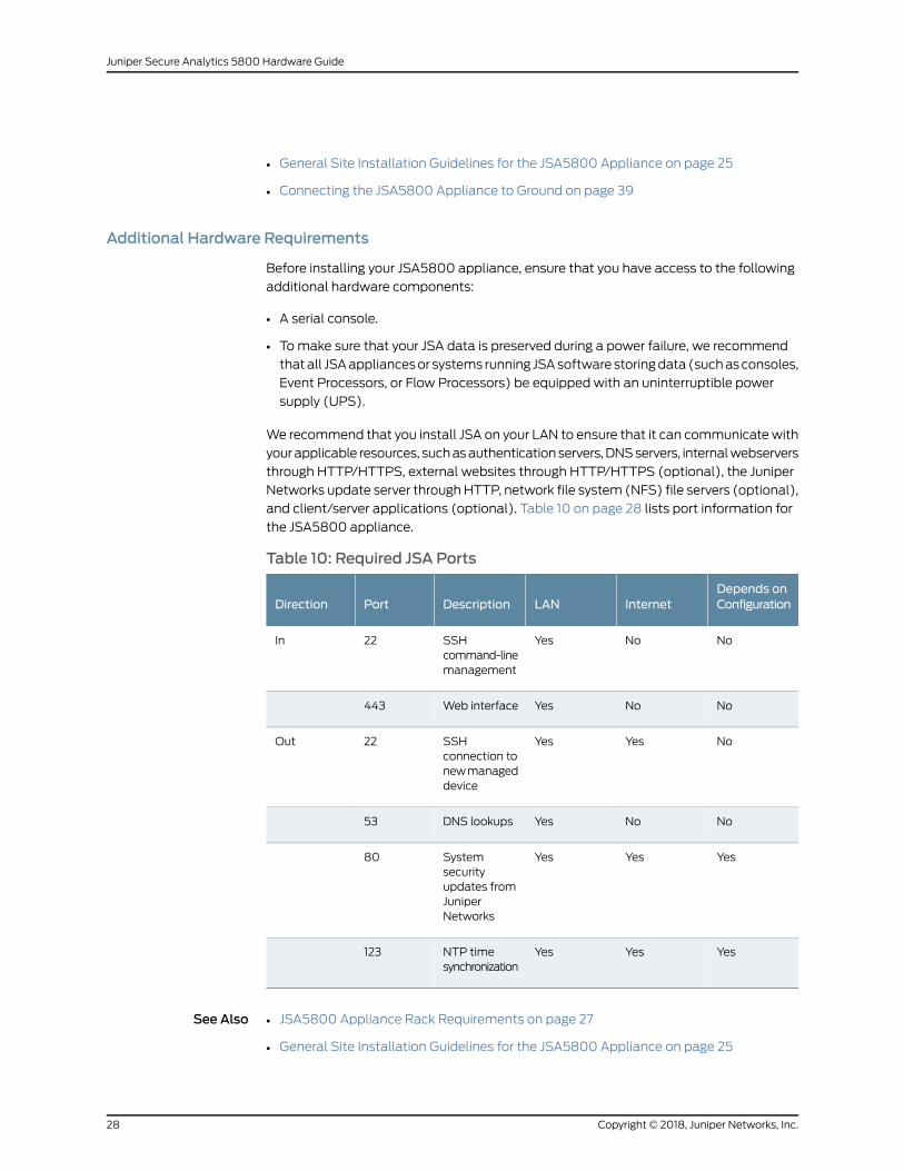
We recommend that you install JSA on your LAN to ensure that it can communicatewith
yourapplicable resources, suchasauthenticationservers,DNSservers, internalwebservers
through HTTP/HTTPS, external websites through HTTP/HTTPS (optional), the Juniper
Networks update server throughHTTP, network file system (NFS) file servers (optional),
and client/server applications (optional). Table 10 on page 28 lists port information for
the JSA5800 appliance.
Table 10: Required JSA Ports
Depends onConfigurationInternetLANDescriptionPortDirection
NoNoYesSSHcommand-linemanagement
22In
NoNoYesWeb interface443
NoYesYesSSHconnection tonewmanageddevice
22Out
NoNoYesDNS lookups53
YesYesYesSystemsecurityupdates fromJuniperNetworks
80
YesYesYesNTP timesynchronization
123
See Also JSA5800 Appliance Rack Requirements on page 27•
• General Site Installation Guidelines for the JSA5800 Appliance on page 25
Copyright © 2018, Juniper Networks, Inc.28
Juniper Secure Analytics 5800 Hardware Guide

RelatedDocumentation
• JSA5800 SystemOverview on page 17
• JSA5800 Chassis on page 19
• JSA5800 Installation Overview on page 31
29Copyright © 2018, Juniper Networks, Inc.
Chapter 2: Site Planning, Preparation, and Specifications

Copyright © 2018, Juniper Networks, Inc.30
Juniper Secure Analytics 5800 Hardware Guide

CHAPTER 3
Initial Installation and Configuration
• JSA5800 Installation Overview on page 31
• Installing the JSA5800 in a Rack on page 32
• Connecting the JSA5800 to Power on page 39
• Connecting the JSA5800 Appliance to a Management Device on page 40
• Configuring the JSA5800 on page 42
JSA5800 Installation Overview
• Overview of Installing the JSA5800 Appliance in a Rack on page 31
• Tools and Parts Required for Installing the JSA5800 Appliance on page 31
Overview of Installing the JSA5800 Appliance in a Rack
The JSA5800appliancecanbe installed ina 19-in. four-post rackasdescribed in “Installing
the JSA5800 Appliance Using Front-and-Rear-Mounting Flush to a Rack” on page 34.
See Also Installing the JSA5800 Appliance Using Front-and-Rear-Mounting Flush to a Rack on
page 34
•
• Tools and Parts Required for Installing the JSA5800 Appliance on page 31
• Installing the JSA5800 Appliance on page 32
Tools and Parts Required for Installing the JSA5800 Appliance
Table 11 on page 31 lists the tools and equipment required for installing andmaintaining
the JSA5800 appliance.
Table 11: Required Tools and Parts for Installing the JSA5800 Appliance
Tools and PartsTask
• Phillips (+) screwdriver, number 1
• Phillips (+) screwdriver, number 3
• Tie wrap
Installing the JSA5800 Appliance
ESD grounding wrist strapConnecting the JSA5800 Appliance
31Copyright © 2018, Juniper Networks, Inc.

Table 11: Required Tools and Parts for Installing the JSA5800Appliance (continued)
Tools and PartsTask
Phillips (+) screwdriver, number 1Grounding the JSA5800 Appliance
• Electrostatic bag or antistatic mat for eachcomponent
• ESD grounding wrist strap
Packing the JSA5800 Appliance
See Also Overview of Installing the JSA5800 Appliance in a Rack on page 31•
• Installing the JSA5800 Appliance Using Front-and-Rear-Mounting Flush to a Rack on
page 34
• Installing the JSA5800 Appliance on page 32
RelatedDocumentation
JSA5800 Site Guidelines and Requirements on page 25•
• Installing the JSA5800 in a Rack on page 32
• Configuring the JSA5800 on page 42
Installing the JSA5800 in a Rack
• Installing the JSA5800 Appliance on page 32
• Installing the JSA5800 Appliance Using Front-and-Rear-Mounting Flush to a
Rack on page 34
Installing the JSA5800 Appliance
Place the shipping container on a flat surface and carefully remove the hardware
components.
To install the JSA5800 appliance:
1. Mount the JSA appliance in your server rack using the attachedmounting brackets.
See “Installing the JSA5800 Appliance Using Front-and-Rear-Mounting Flush to a
Rack” on page 34.
2. Plug the power cords into each of the AC receptacle on the rear panel. See
Figure 5 on page 33.
Copyright © 2018, Juniper Networks, Inc.32
Juniper Secure Analytics 5800 Hardware Guide

Figure 5: Connecting the AC Power Cord
3. Plug the other end of the power cords into the wall socket.
Plug eachpower cord intoa separatepower circuit to ensure that thedevice continues
to receive power if one of the power circuits fails.
4. Plug the Ethernet cable into the Ethernet port on the back panel.
When you turn on the power, the internal port uses two LEDs to indicate the LAN
connection status, as shown in Figure 6 on page 33.
Figure 6: LEDs on the JSA5800
g000632
1
2
3
4
5
6
4—1— Hard Drive LEDPower LED
5—2— LAN1 LEDLAN2 LED
6—3— Information LEDAlert/Power fail LED
5. Plug a RS-232 (DB-9 F/F) cable into the console port. This cable is a console cable
and DB-9 connector with 1-8 pinouts. The connector is shipped with your JSA5800
appliance.
Table 12onpage34describes thedetails ofDB-9consoleportpinouts for the JSA5800
appliance.
33Copyright © 2018, Juniper Networks, Inc.
Chapter 3: Initial Installation and Configuration

Table 12: DB-9 Console Connector Pinouts for the JSA5800 Appliance
DescriptionSignalPin
Data Carrier DetectDCD1
Receive DataRxD2
Transmit DataTxD Output3
Data Terminal ReadyDTR Output4
Chassis GroundGND5
Data Set ReadyDSR Input6
Request to SendRTS Output7
Clear to SendCTS Input8
Ring IndicatorRI9
Not ConnectedNC10
6. Push the power button on the front panel.
The power LED below the power button turns on.
See Also Connecting the JSA5800 Appliance to a Management Device on page 40•
• Connecting the JSA5800 Appliance to Ground on page 39
• Connecting the JSA5800 to Power on page 39
Installing the JSA5800 Appliance Using Front-and-Rear-Mounting Flush to a Rack
Thechassis package includesapair of rack rail assembliesandmounting screws required
to install the chassis in a rack. Each rail assembly consists of an inner, a middle, and an
outer rail, as shown in Figure 7 on page 35.
Copyright © 2018, Juniper Networks, Inc.34
Juniper Secure Analytics 5800 Hardware Guide

Figure 7: Identifying the Inner, Middle, and Outer Rails
4—1— Outer railInner rail
5—2— Locking tabLocking tab
3—Middle rail
35Copyright © 2018, Juniper Networks, Inc.
Chapter 3: Initial Installation and Configuration

Tomount the JSA5800 appliance in a four-post rack:
1. Install the inner rail extensions.
a. Pull the inner rail out of the outer rail until it is fully extended as illustrated. Press
the locking tabdown to release the inner rail, as shown in Figure8onpage36. Each
inner rail has a locking tab that secures the chassis when completely extended
from the rack.
Figure 8: Sliding and Detaching the Inner Rails
b. Place the inner rails against the sides of the chassis, aligning the chassis hooks
with the holes in the inner rails, as shown in Figure 9 on page 36.
c. Slide the inner rail toward the front of the chassis until the inner rail clicks into the
locked position.
d. Secure the inner rails to the chassis with the screws provided.
Figure 9: Installing the Inner Rails
2
NOTE: Each inner rail of the JSA5800 appliance has a locking tab. Thelocking tabs secure the chassis when it is either installed or completelyextended from the rack.
2. Install the outer rails:
a. Press the locking tabs upward at the rear of the middle rails, and slide the middle
rails into the outer rails.
b. Insert the front hooks of the outer rails into the front slots of the rack, and use the
M5 screws to secure the front of the outer rails to the rack, as shown in
Figure 10 on page 37 and Figure 11 on page 37.
Copyright © 2018, Juniper Networks, Inc.36
Juniper Secure Analytics 5800 Hardware Guide

Figure 10: Inserting the Front Mounting Rails
c. Extend the outer rails, and adjust the length to fit within the posts of the rack.
d. Insert the rear hooks of the outer rails into the rear slots of the rack, and use the
screws to secure the rear of the outer rails to the rack, as shown in
Figure 11 on page 37.
Figure 11: Inserting the Front and Rear Mounting Rails
3. Slide the middle rails away from the rear of the outer rails.
4. Position the ball-bearing shuttle at the front of the middle rails.
5. Align the chassis inner rails with the ball-bearing shuttle, as shown in
Figure 12 on page 38.
37Copyright © 2018, Juniper Networks, Inc.
Chapter 3: Initial Installation and Configuration
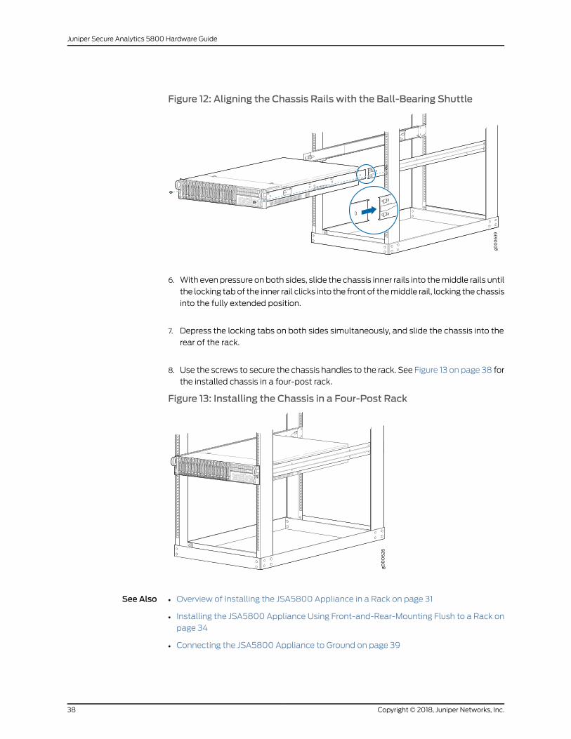
Figure 12: Aligning the Chassis Rails with the Ball-Bearing Shuttle
2
6. With evenpressure onboth sides, slide the chassis inner rails into themiddle rails until
the locking tabof the inner rail clicks into the front of themiddle rail, locking the chassis
into the fully extended position.
7. Depress the locking tabs on both sides simultaneously, and slide the chassis into the
rear of the rack.
8. Use the screws to secure the chassis handles to the rack. See Figure 13 on page 38 for
the installed chassis in a four-post rack.
Figure 13: Installing the Chassis in a Four-Post Rack
2
See Also Overview of Installing the JSA5800 Appliance in a Rack on page 31•
• Installing the JSA5800 Appliance Using Front-and-Rear-Mounting Flush to a Rack on
page 34
• Connecting the JSA5800 Appliance to Ground on page 39
Copyright © 2018, Juniper Networks, Inc.38
Juniper Secure Analytics 5800 Hardware Guide

RelatedDocumentation
JSA5800 Site Guidelines and Requirements on page 25•
• JSA5800 Installation Overview on page 31
• Configuring the JSA5800 on page 42
Connecting the JSA5800 to Power
• Connecting the JSA5800 Appliance to Ground on page 39
• Connecting the JSA5800 Appliance to a DC Power Source on page 39
Connecting the JSA5800 Appliance to Ground
Tomeet safety and electromagnetic interference (EMI) requirements and to ensure
properoperation, youmustadequately ground the JSA5800appliancebefore connecting
it to the power source.
Grounding for the JSA5800 appliance is provided through the power supply ground.
Ensure that you connect the AC power supplymodule in the appliance to a grounded AC
power outlet by using an AC power cord (with the grounding pin) appropriate for your
geographical location.
See Also Installing the JSA5800 Appliance on page 32•
• JSA5800 Appliance Back Panel Description on page 21
Connecting the JSA5800 Appliance to a DC Power Source
Before connecting your JSA5800 appliance to a DC power source:
• Ensure that you have taken the necessary precautions to prevent ESD damage.
• Ensure that you have connected the JSA5800 appliance chassis to earth ground.
Required tools and parts:
• DCpower sourcecables (12-14AWG)withendsof thewire stripped~12mmand twisted
• Phillips (+) screwdriver, number 1
CAUTION: Before you connect power to the JSA5800 appliance, attach theground wire in one of the below configurations tomeet the safetyrequirements and to ensure proper operation:
• Both power supply ground terminals
• One or both of the chassis ground terminal(s) located to the left of thepower supply modules
• Both power supply ground terminals and one or both chassis groundterminals
39Copyright © 2018, Juniper Networks, Inc.
Chapter 3: Initial Installation and Configuration
You connect a DC power source to the JSA5800 appliance by attaching power cables
from the external DC power sources to the terminal studs on the DC power feed
faceplates.
WARNING: DC-powered JSA appliances are intended for installation only inrestricted access locations.
WARNING: Before you perform the following procedure, ensure that poweris removed from the DC circuit. To ensure that all power is off, locate thecircuit breaker on the panel board that services the DC circuit, switch thecircuit breaker to the OFF position, and tape the switch handle of the circuitbreaker in the OFF position.
To connect the DC source power to the JSA5800 appliance:
1. Ensure that the input circuit breaker is open so that the voltage across the DC power
source cable leads is 0 V, and so that the cable leads will not become active while
you are connecting DC power.
2. Connect the black wire to the -48 V terminal block and red wire to the RTN terminal
block on the back panel of the JSA5800 appliance.
3. Use the terminal screws to secure the power source cables to the power feed on the
JSA5800 appliance.
4. Attach the plastic safety cover.
See Also Connecting the JSA5800 Appliance to a Management Device on page 40•
• Installing the JSA5800 Appliance on page 32
RelatedDocumentation
JSA5800 Installation Overview on page 31•
• Installing the JSA5800 in a Rack on page 32
• Configuring the JSA5800 on page 42
Connecting the JSA5800 Appliance to aManagement Device
You can control the JSA5800appliance through a connectedmanagement device (such
asa laptop).Use theconsoleport toconnect your laptopasshown inFigure 14onpage41.
Copyright © 2018, Juniper Networks, Inc.40
Juniper Secure Analytics 5800 Hardware Guide

Figure 14: Connecting theManagement Device
Refer to the JSA5800 Back Panel Components table for the location of the ports in
“JSA5800 Appliance Back Panel Description” on page 21.
NOTE: You can choose any GB ports as themanagement port.
To connect a management device with the JSA5800 appliance:
1. Connect external devices using the ports on the back panel of the appliance.
2. If you use a laptop, connect the laptop to the DB-9 serial console port on the back
panel.
3. Plug an Ethernet cable into the network port on the back panel.
4. Plug a RS-232 (DB-9 F/F) cable into the console port.
NOTE: When using a laptop to connect to the appliance, youmust use aterminal program, such as HyperTerminal, to connect to the appliance.
5. Select the appropriate COM port to use.
6. Configure the following port settings:
• Bits per second = 9600
• Stop bits = 1
41Copyright © 2018, Juniper Networks, Inc.
Chapter 3: Initial Installation and Configuration

• Data bits = 8
• Parity = None
RelatedDocumentation
Connecting the JSA5800 to Power on page 39•
• Installing the JSA5800 Appliance on page 32
Configuring the JSA5800
• Configuring Basic Settings on the JSA5800 Appliance on page 42
• Accessing the JSA Interface on page 44
Configuring Basic Settings on the JSA5800 Appliance
To configure the basic setting using the JSA interface:
NOTE: When using a laptop to connect to the appliance, youmust use aterminal program, such as HyperTerminal, to connect to the appliance.
1. At the console prompt, log in as root (default username). No password is required
when you log in for the first time.
NOTE: The username is case sensitive.
2. Press Enter. The End User License Agreement (EULA) appears.
3. Read the information and press the Spacebar to advance eachwindowuntil you have
reached the end of the agreement.
4. Type YES to accept the agreement, then press Enter. The Appliance ID selectionwindow appears.
NOTE: Although your current position is not highlighted, use the up ordown arrow keys and Spacebar to select an option. Use the left or rightarrow keys to select Next.
5. Select the appliance ID and then press Enter to select Next.
6. Select normal from the following types of setup:
• normal—Default setup
Copyright © 2018, Juniper Networks, Inc.42
Juniper Secure Analytics 5800 Hardware Guide
• recovery—HA recovery setup
7. Select Next. The Tuning Template window appears.
8. Select Enterprise and then select Next. The Date and Time window appears.
9. Select the method you want to use to set the date and time:
• Manual–Allows you to manually input the date and time. Select Next.
• Server–Allows you to specify your time server. Select Next.
10. Select your time zone continent or area, and then select Next.
11. Select your time zone region, and then select Next. The options appearing in this
window are regions associated with the continent or area previously selected.
12. Select one of the following Internet protocols, IPv6 or IPv4.
13. Select Next. The Management Interface window appears.
14. Select the interface you want to specify as the management interface and select
Next.
15. To configure the JSA network settings, enter the values for the following parameters.
Use the up or down arrow keys to navigate the fields:
• Hostname—Type a fully qualified domain name (FQDN) as the system hostname.
• IP Address—Specify the IP address of the system.
• Netmask—Specify the network mask address for the system.
• Gateway—Specify the default gateway for the system.
• Primary DNS—Specify the primary DNS server.
• Secondary DNS—(Optional) Specify the secondary DNS server.
• Public IP—(Optional) Specify the public IP address of the server. The server uses
this IP address to communicate with another server that belongs to a different
network using Network Address Translation (NAT). NAT translates an IP address
in one network to a different IP address in another network.
• Email Server—Specify the e-mail server. If you do not have an e-mail server, specify
the local host in this field.
16. Use Tab to select Next. Press Enter. The New Root Password window appears.
17. To configure the JSA root password:
a. Type a new password.
43Copyright © 2018, Juniper Networks, Inc.
Chapter 3: Initial Installation and Configuration

b. Select Next and then press Enter. The Confirm New Root Password window
appears.
c. Reenter your new password to confirm, and select Finish.
A series of messages appears as JSA continues with the installation; this process
takes from three to five minutes. When the JSA installation process is complete,
the message window appears.
18. Press Enter and selectOK to complete the installation.
You are now ready to access JSA. For more information, see “Accessing the JSA
Interface” on page 44.
19. Type exit and press Enter.
See Also Accessing the JSA Interface on page 44•
• JSA5800 Appliance Physical Specifications on page 26
• Connecting the JSA5800 Appliance to a Management Device on page 40
Accessing the JSA Interface
Purpose To access a Juniper Secure Analytics (JSA) interface:
Action Open yourWeb browser.1.
NOTE: JSA supports the following browsers:
• 32-bit Microsoft Internet Explorer, with documentmode and browsermode enabled - 8.0 and 9.0
• Mozilla Firefox - 17.0 ESR and 24.0 ESR
NOTE: Because of Mozilla’s short release cycle, we cannotcommit to testing on the latest versions of theMozilla FirefoxWeb browser. However, we are fully committed toinvestigating any issues that are reported.
• Google Chrome - Latest version
2. Log in to JSA:
https://<IP Address>
<IP Address> is the IP address of the JSA system.
The default values are:
Username: admin
Copyright © 2018, Juniper Networks, Inc.44
Juniper Secure Analytics 5800 Hardware Guide

Password: <root password>
<root password> is the new root password you set during the installation process.
3. Click Login To JSA.
The JSA interface appears. You are now ready to start tuning JSA and high availability
(HA) settings. For more information, see the Juniper Secure Analytics Administration
Guide.
NOTE: Youwill need a permanent license for the JSA appliance to upgradeto a higher version. If you have a temporary license, the upgrade will fail; runthe installer again to upgrade to a higher version.
See Also Configuring Basic Settings on the JSA5800 Appliance on page 42•
• Connecting the JSA5800 Appliance to a Management Device on page 40
RelatedDocumentation
• JSA5800 Installation Overview on page 31
• Installing the JSA5800 in a Rack on page 32
• Connecting the JSA5800 to Power on page 39
45Copyright © 2018, Juniper Networks, Inc.
Chapter 3: Initial Installation and Configuration

Copyright © 2018, Juniper Networks, Inc.46
Juniper Secure Analytics 5800 Hardware Guide

CHAPTER 4
Maintaining Components
• Maintaining the JSA5800 RAID Array on page 47
• Maintaining JSA5800 Power System on page 48
Maintaining the JSA5800 RAID Array
Redundant array of independent disk (RAID) is amethod of usingmultiple disks to store
the samedata indifferent locations to increase fault toleranceand improveperformance.
A RAID array is used in the servers for data storage and to replicate data amongmultiple
hard disk drives. There are different RAID levels designed to increase data reliability and
I/O performance.
The key concepts in RAID are:
• Mirroring—Copy data to more than one disk
• Striping—Split data across more than one disk
• Error correction—Redundant data storage to detect and resolve problems
The JSA5800 appliance uses the RAID10 configuration. In RAID10, drives are duplicated
for fault tolerance.
Tomonitor the JSA5800 RAID array, use the following commands:
• For the RAID status, use /opt/MegaRAID/MegaCli/MegaCli64 -LDinfo -Lall -a 0
• For the driver status, use /opt/MegaRAID/MegaCli/MegaCli64 -PDList -a 0 |more
• For the RAID consistency check, schedule through cron or use
/opt/MegaRAID/MegaCli/MegaCli64 -LDCC -Start -Lall -a 0
RelatedDocumentation
JSA5800 Appliance Physical Specifications on page 26•
• JSA5800 Appliance Front Panel Description on page 19
• JSA5800 Appliance Back Panel Description on page 21
47Copyright © 2018, Juniper Networks, Inc.

Maintaining JSA5800 Power System
• Maintaining the JSA5800 Power Supply on page 48
• Replacing an AC Power Supply on the JSA5800 Appliance on page 49
• Replacing AC Power Supply Cables on the JSA5800 Appliance on page 49
• Replacing a DC Power Supply on the JSA5800 Appliance on page 50
• Replacing DC Power Supply Cables on the JSA5800 Appliance on page 51
Maintaining the JSA5800 Power Supply
The JSA5800 appliances ship with redundant AC power supply modules. If one power
supply fails, the second power supply takes over for the entire power load.
NOTE: The JSA5800also supports optionalDCpower supplymodules if youneed DC power.
Tomaintain the power supplies, follow these guidelines:
• Ensure that the power and grounding cables are arranged so that they do not obstruct
access to other components.
• Routinely check the power LED on the power supplymodule. If the LED status is green,
the power supply is functioning normally.
• Periodically inspect the site to ensure that the grounding and power cables connected
to the JSA5800 appliance are securely in place and that there nomoisture is
accumulating near the appliance.
Tomonitor the power supply modules, execute the following commands:
• To enable IPMI and boot, use # chkconfig ipmi on
• To start IPMI service, use service ipmi start
• To load IPMI driver, usemodprobe ipmi_devintf
For example, the following load driver is displayed:
[root@hw-jsa5800 ~]# lsmod |grep ipmi
ipmi_devintf 7729 Ø
• For the IPMI hardware status, use # ipmitool sdr
See Also JSA5800 Appliance Physical Specifications on page 26•
• JSA5800 Appliance Front Panel Description on page 19
• JSA5800 Appliance Back Panel Description on page 21
Copyright © 2018, Juniper Networks, Inc.48
Juniper Secure Analytics 5800 Hardware Guide

Replacing an AC Power Supply on the JSA5800 Appliance
To replace an AC power supply:
1. Attach an ESD grounding strap to your bare wrist and connect the strap to one of the
ESD points on the chassis.
2. Remove the power cord from the power supply.
3. Push the tab on the left edge of the power supply to the right.
4. Pull the power supply straight out of the chassis using the provided handle. Use one
hand to support underneath the supply as you remove it.
5. Orient the replacement power supply so that the tab is on the left side.
6. Using both hands, slide the replacement power supply straight into the chassis until
the power supply is fully seated in the chassis slot. Make sure the tab on the left edge
of the power supply clicks into place.
7. Attach the power cord to the power supply. If the power supply is correctly installed
and functioning normally, the power supply powers up immediately.
See Also Field-Replaceable Units on the JSA5800 Appliance on page 18•
• Replacing AC Power Supply Cables on the JSA5800 Appliance on page 49
• Contacting Juniper Networks Technical Assistance Center on page 53
Replacing AC Power Supply Cables on the JSA5800 Appliance
To replace an AC power supply cord:
1. Unplug the power cord from the power source receptacle.
2. Attach an ESD grounding strap to your bare wrist and connect the strap to one of the
ESD points on the chassis.
3. Unplug the power cord from the appliance inlet on the power supply.
4. Locate a replacement power cord with the type of plug appropriate for your
geographical location.
5. Insert the power cord plug into an external AC power source receptacle.
49Copyright © 2018, Juniper Networks, Inc.
Chapter 4: Maintaining Components

6. Connect the power cord to the power supply.
7. Verify that the power cord does not block the air exhaust and access to device
components, or drape where people could trip on it.
8. If the power supply is correctly installed and functioning normally, the supply
automatically powers up.
See Also Field-Replaceable Units on the JSA5800 Appliance on page 18•
• Contacting Juniper Networks Technical Assistance Center on page 53
• Replacing an AC Power Supply on the JSA5800 Appliance on page 49
Replacing a DC Power Supply on the JSA5800 Appliance
To replace a DC power supply:
1. Switch off the dedicated facility circuit breaker for the power supply being removed.
2. Make sure that the voltage across the DC power source cable leads is 0 V and that
there is no chance that the cables might become active during the removal process.
3. Attach an ESD grounding strap to your bare wrist and connect the strap to one of the
ESD points on the chassis.
4. Remove the clear plastic cover protecting the terminal studs on the faceplate.
5. Remove the screws from the terminals. Use a number-2 Phillips screwdriver to loosen
and remove the screws.
6. Remove the cable lugs from the terminals.
7. Carefully move the power cables out of the way.
8. Push the tab on the left edge of the power supply to the left.
9. Pull the power supply straight out of the chassis.
10. Using both hands, slide the replacement power supply straight into the chassis until
the power supply is fully seated in the chassis slot. Make sure the tab on the left edge
of the power supply clicks into place.
11. To connect the DC source power to the JSA5800 appliance, see “Connecting the
JSA5800 to Power” on page 39.
Copyright © 2018, Juniper Networks, Inc.50
Juniper Secure Analytics 5800 Hardware Guide

See Also Field-Replaceable Units on the JSA5800 Appliance on page 18•
• Contacting Juniper Networks Technical Assistance Center on page 53
• Replacing DC Power Supply Cables on the JSA5800 Appliance on page 51
Replacing DC Power Supply Cables on the JSA5800 Appliance
To replace a DC power supply cable connected to a JSA5800 appliance:
1. Attach an ESD grounding strap to your bare wrist and connect the strap to one of the
ESD points on the chassis.
2. Switch off the external circuit breakers for all the cables attached to thepower supply.
Make sure that the voltage across the DC power source cable leads is 0 V and that
there is no chance that the cables might become active during the removal process.
3. Remove the clear plastic cover over the terminal studs on the faceplate.
4. Remove the power cable from the DC power source.
NOTE: Ensure the cable is not touching or in theway of any components,and that it does not drape where people could trip on it.
5. Attach thepower cable to theDCpower source. Formore information, see “Connecting
the JSA5800 to Power” on page 39.
6. Replace the clear plastic cover over the terminal studs on the faceplate.
7. If the power supply is correctly installed and functioning normally, the supply
automatically powers up.
See Also Field-Replaceable Units on the JSA5800 Appliance on page 18•
• Contacting Juniper Networks Technical Assistance Center on page 53
• Replacing a DC Power Supply on the JSA5800 Appliance on page 50
RelatedDocumentation
• Connecting the JSA5800 to Power on page 39
• JSA5800 Chassis on page 19
51Copyright © 2018, Juniper Networks, Inc.
Chapter 4: Maintaining Components

Copyright © 2018, Juniper Networks, Inc.52
Juniper Secure Analytics 5800 Hardware Guide

CHAPTER 5
Troubleshooting Hardware
• Contacting Juniper Networks Technical Assistance Center on page 53
Contacting Juniper Networks Technical Assistance Center
You can contact Juniper Networks Technical Assistance Center (JTAC) 24 hours a day,
7 days a week in one of the following ways:
• On theWeb, using the Case Manager link at: https://www.juniper.net/support/
• By telephone:
• From the US and Canada: 1-888-314-JTAC
• From all other locations: 1-408-745-9500
If contacting JTAC by phone, enter your 12-digit case number followed by the # key if
this is an existing case, or press the * key to be routed to the next available support
engineer.
When requesting support from JTAC by telephone, be prepared to provide the following
information:
• Your existing case number, if you have one
• Details of the failure or problem
• Type of activity being performed on the platformwhen the problem occurred
• Configuration data using one or more of the show commands
RelatedDocumentation
• Maintaining the JSA5800 RAID Array on page 47
• Maintaining the JSA5800 Power Supply on page 48
• Field-Replaceable Units on the JSA5800 Appliance on page 18
• Knowledge Base
53Copyright © 2018, Juniper Networks, Inc.

Copyright © 2018, Juniper Networks, Inc.54
Juniper Secure Analytics 5800 Hardware Guide

CHAPTER 6
Safety and Compliance Information
• Definitions of SafetyWarning Levels on page 56
• General Safety Guidelines andWarnings on page 57
• Restricted AccessWarning on page 58
• Qualified Personnel Warning on page 60
• Prevention of Electrostatic Discharge Damage on page 61
• Warning Statement for Norway and Sweden on page 62
• Fire Safety Requirements on page 62
• Installation InstructionsWarning on page 63
• Chassis Lifting Guidelines for the JSA5800 Appliance on page 64
• RampWarning on page 65
• Rack-Mounting and Cabinet-MountingWarnings on page 65
• Grounded EquipmentWarning on page 69
• Laser and LED Safety Guidelines andWarnings on page 70
• Radiation fromOpen Port AperturesWarning on page 72
• Maintenance and Operational Safety Guidelines andWarnings on page 73
• Action to Take After an Electrical Accident on page 79
• General Electrical Safety Guidelines andWarnings on page 79
• AC Power Electrical Safety Guidelines on page 80
• AC Power DisconnectionWarning on page 81
• DC Power Electrical Safety Guidelines on page 83
• DC Power DisconnectionWarning on page 84
• DC Power Grounding Requirements andWarning on page 85
• DC PowerWiring SequenceWarning on page 86
• Multiple Power Supplies DisconnectionWarning on page 88
• TN PowerWarning on page 89
• Agency Approvals for the JSA5800 Appliance on page 89
• ComplianceStatements forEMCRequirements for the JSA5800Applianceonpage90
• Compliance Statements for Acoustic Noise for the JSA5800 Appliance on page 93
55Copyright © 2018, Juniper Networks, Inc.

Definitions of SafetyWarning Levels
The documentation uses the following levels of safety warnings (there are twoWarning
formats):
NOTE: Youmight find this information helpful in a particular situation, or youmight overlook this important information if it was not highlighted in a Note.
CAUTION: You need to observe the specified guidelines to prevent minorinjury or discomfort to you or severe damage to the device.
WARNING: This symbol alerts you to the risk of personal injury from a laser.
WARNING: This symbolmeansdanger.Youare inasituation thatcouldcausebodily injury. Before you work on any equipment, be aware of the hazardsinvolved with electrical circuitry and be familiar with standard practices forpreventing accidents.
Waarschuwing Dit waarschuwingssymbool betekent gevaar. U verkeert ineen situatie die lichamelijk letsel kan veroorzaken. Voordat u aan enigeapparatuur gaat werken, dient u zich bewust te zijn van de bij elektrischeschakelingen betrokken risico's en dient u opde hoogte te zijn van standaardmaatregelen om ongelukken te voorkomen.
Varoitus Tämä varoitusmerkki merkitsee vaaraa. Olet tilanteessa, joka voijohtaa ruumiinvammaan.Ennenkuin työskenteletminkään laitteistonparissa,ota selvää sähkökytkentöihin liittyvistä vaaroista ja tavanomaisistaonnettomuuksien ehkäisykeinoista.
AttentionCe symbole d'avertissement indique un danger. Vous vous trouvezdansunesituationpouvantcauserdesblessuresoudesdommagescorporels.Avant de travailler sur un équipement, soyez conscient des dangers poséspar les circuits électriques et familiarisez-vous avec les procédurescouramment utilisées pour éviter les accidents.
Warnung DiesesWarnsymbol bedeutet Gefahr. Sie befinden sich in einerSituation, die zu einer Körperverletzung führen könnte. Bevor Sie mit derArbeit an irgendeinemGerät beginnen, seien Sie sich der mit elektrischenStromkreisen verbundenen Gefahren und der Standardpraktiken zurVermeidung von Unfällen bewußt.
AvvertenzaQuesto simbolo di avvertenza indica un pericolo. La situazionepotrebbe causare infortuni alle persone. Prima di lavorare su qualsiasi
Copyright © 2018, Juniper Networks, Inc.56
Juniper Secure Analytics 5800 Hardware Guide

apparecchiatura, occorre conoscere i pericoli relativi ai circuiti elettrici edessere al corrente delle pratiche standard per la prevenzione di incidenti.
AdvarselDette varselsymbolet betyr fare. Du befinner deg i en situasjon somkan føre til personskade. Før du utfører arbeid på utstyr, må du vareoppmerksom på de faremomentene som elektriske kretser innebærer, samtgjøre deg kjent med vanlig praksis når det gjelder å unngå ulykker.
Aviso Este símbolo de aviso indica perigo. Encontra-se numa situação quelhepoderá causar danos físicos. Antes de começar a trabalhar comqualquerequipamento, familiarize-se com os perigos relacionados com circuitoseléctricos, e com quaisquer práticas comuns que possam prevenir possíveisacidentes.
¡Atención! Este símbolo de aviso significa peligro. Existe riesgo para suintegridad física. Antes demanipular cualquier equipo, considerar los riesgosque entraña la corriente eléctrica y familiarizarse con los procedimientosestándar de prevención de accidentes.
Varning!Denna varningssymbol signalerar fara. Du befinner dig i en situationsom kan leda till personskada. Innan du utför arbete på någon utrustningmåste du varamedveten om farornamed elkretsar och känna till vanligtförfarande för att förebygga skador.
RelatedDocumentation
General Safety Guidelines andWarnings on page 57•
• Installation InstructionsWarning on page 63
• Maintenance and Operational Safety Guidelines andWarnings on page 73
• Grounded EquipmentWarning on page 69
• Laser and LED Safety Guidelines andWarnings on page 70
• Laser and LED Safety Guidelines andWarnings for the ACX5000 Router
• Warning Statement for Norway and Sweden on page 62
General Safety Guidelines andWarnings
The following guidelines help ensure your safety and protect the device from damage.
The list of guidelinesmightnotaddressall potentially hazardoussituations in yourworking
environment, so be alert and exercise good judgment at all times.
• Perform only the procedures explicitly described in the hardware documentation for
this device. Make sure that only authorized service personnel perform other system
services.
• Keep the area around the device clear and free from dust before, during, and after
installation.
• Keep tools away from areas where people could trip over themwhile walking.
57Copyright © 2018, Juniper Networks, Inc.
Chapter 6: Safety and Compliance Information

• Do not wear loose clothing or jewelry, such as rings, bracelets, or chains, which could
become caught in the device.
• Wear safety glasses if you are working under any conditions that could be hazardous
to your eyes.
• Do not perform any actions that create a potential hazard to people or make the
equipment unsafe.
• Never attempt to lift an object that is too heavy for one person to handle.
• Never install or manipulate wiring during electrical storms.
• Never install electrical jacks in wet locations unless the jacks are specifically designed
for wet environments.
• Operate the device only when it is properly grounded.
• Ensure that the separate protective earthing terminal provided on this device is
permanently connected to earth.
• Replace fuses only with fuses of the same type and rating.
• Do not open or remove chassis covers or sheet-metal parts unless instructions are
provided in the hardware documentation for this device. Such an action could cause
severe electrical shock.
• Do not push or force any objects through any opening in the chassis frame. Such an
action could result in electrical shock or fire.
• Avoid spilling liquid onto the chassis or onto any device component. Such an action
could cause electrical shock or damage the device.
• Avoid touching uninsulated electrical wires or terminals that have not been
disconnected from their power source. Such an action could cause electrical shock.
• Always ensure that all modules, power supplies, and cover panels are fully inserted
and that the installation screws are fully tightened.
RelatedDocumentation
AC Power Electrical Safety Guidelines on page 80•
• General Electrical Safety Guidelines andWarnings on page 79
• Maintenance and Operational Safety Guidelines andWarnings on page 73
• Installation InstructionsWarning on page 63
• Grounded EquipmentWarning on page 69
Restricted AccessWarning
WARNING: This unit is intended for installation in restricted access areas. Arestrictedaccessarea isanarea towhichaccesscanbegainedonlybyservicepersonnel through the use of a special tool, lock and key, or other means ofsecurity, andwhich is controlled by the authority responsible for the location.
Copyright © 2018, Juniper Networks, Inc.58
Juniper Secure Analytics 5800 Hardware Guide

WaarschuwingDit toestel isbedoeldvoor installatieopplaatsenmetbeperktetoegang.Eenplaatsmetbeperkte toegang iseenplaatswaar toegangslechtsdoor servicepersoneel verkregen kan worden door middel van een speciaalinstrument, een slot en sleutel, of een ander veiligheidsmiddel, en welkebeheerd wordt door de overheidsinstantie die verantwoordelijk is voor delocatie.
Varoitus Tämä laite on tarkoitettu asennettavaksi paikkaan, johon pääsy onrajoitettua. Paikka, johon pääsy on rajoitettua, tarkoittaa paikkaa, johon vainhuoltohenkilöstö pääsee jonkin erikoistyökalun, lukkoon sopivan avaimentai jonkin muun turvalaitteen avulla ja joka on paikasta vastuussa olevientoimivaltaisten henkilöiden valvoma.
Attention Cet appareil est à installer dans des zones d'accès réservé. Cesdernières sontdeszonesauxquelles seul lepersonneldeservicepeutaccéderen utilisant un outil spécial, unmécanisme de verrouillage et une clé, ou toutautre moyen de sécurité. L'accès aux zones de sécurité est sous le contrôlede l'autorité responsable de l'emplacement.
Warnung Diese Einheit ist zur Installation in Bereichenmit beschränktemZutritt vorgesehen. Ein Bereichmit beschränktem Zutritt ist ein Bereich, zudem nurWartungspersonal mit einem Spezialwerkzeugs, Schloß undSchlüssel oder anderer Sicherheitsvorkehrungen Zugang hat, und der vondem für die Anlage zuständigen Gremium kontrolliert wird.
AvvertenzaQuestaunitàdeveessere installata inun'areaadaccesso limitato.Un'area ad accesso limitato è un'area accessibile solo a personale diassistenza tramite un'attrezzo speciale, lucchetto, o altri dispositivi disicurezza, ed è controllata dall'autorità responsabile della zona.
Advarsel Denne enheten er laget for installasjon i områder med begrensetadgang.Etområdemedbegrensetadganggir kunadgangtil servicepersonalesom bruker et spesielt verktøy, lås og nøkkel, eller en annensikkerhetsanordning, og det kontrolleres av den autoriteten som er ansvarligfor området.
AvisoEstaunidade foi concebidapara instalaçãoemáreasdeacesso restrito.Uma área de acesso restrito é uma área à qual apenas temacesso o pessoalde serviço autorizado, que possua uma ferramenta, chave e fechaduraespecial, ou qualquer outra forma de segurança. Esta área é controlada pelaautoridade responsável pelo local.
¡Atención! Esta unidad ha sido diseñada para instalarse en áreas de accesorestringido. Área de acceso restringido significa un área a la que solamentetieneaccesoelpersonaldeserviciomediante lautilizacióndeunaherramientaespecial, cerradura con llave, o algún otromedio de seguridad, y que estábajo el control de la autoridad responsable del local.
Varning! Denna enhet är avsedd för installation i områdenmed begränsattillträde. Ett områdemed begränsat tillträde får endast tillträdas av
59Copyright © 2018, Juniper Networks, Inc.
Chapter 6: Safety and Compliance Information

servicepersonal med ett speciellt verktyg, lås och nyckel, eller annansäkerhetsanordning, och kontrolleras av den auktoritet som ansvarar förområdet.
RelatedDocumentation
General Safety Guidelines andWarnings on page 57•
• General Electrical Safety Guidelines andWarnings on page 79
• Installation InstructionsWarning on page 63
• Grounded EquipmentWarning on page 69
Qualified PersonnelWarning
WARNING: Only trainedandqualified personnel should install or replace thedevice.
Waarschuwing Installatie en reparaties mogen uitsluitend door getraind enbevoegd personeel uitgevoerd worden.
VaroitusAinoastaankoulutettu japätevähenkilökuntasaaasentaatai vaihtaatämän laitteen.
Attention Tout installation ou remplacement de l'appareil doit être réalisépar du personnel qualifié et compétent.
WarnungGerät nur vongeschultem, qualifiziertemPersonal installierenoderauswechseln lassen.
Avvertenza Solo personale addestrato e qualificato deve essere autorizzatoad installare o sostituire questo apparecchio.
Advarsel Kun kvalifisert personell med riktig opplæring bør montere ellerbytte ut dette utstyret.
Aviso Este equipamento deverá ser instalado ou substituído apenas porpessoal devidamente treinado e qualificado.
¡Atención! Estos equipos deben ser instalados y reemplazadosexclusivamenteporpersonal técnicoadecuadamentepreparadoycapacitado.
Varning! Denna utrustning ska endast installeras och bytas ut av utbildadoch kvalificerad personal.
RelatedDocumentation
General Safety Guidelines andWarnings on page 57•
• General Electrical Safety Guidelines andWarnings on page 79
• AC Power Electrical Safety Guidelines on page 80
Copyright © 2018, Juniper Networks, Inc.60
Juniper Secure Analytics 5800 Hardware Guide

• DC Power Electrical Safety Guidelines for Switches
Prevention of Electrostatic Discharge Damage
Device components that are shipped in antistatic bags are sensitive to damage from
static electricity. Some components can be impaired by voltages as low as 30 V. You
can easily generate potentially damaging static voltages whenever you handle plastic
or foam packing material or if youmove components across plastic or carpets. Observe
the following guidelines to minimize the potential for electrostatic discharge (ESD)
damage, which can cause intermittent or complete component failures:
• AlwaysuseanESDgroundingstrapwhenyouarehandlingcomponents thatare subject
to ESD damage, andmake sure that it is in direct contact with your skin.
If a grounding strap is not available, hold the component in its antistatic bag (see
Figure 15 on page 62) in one hand and touch the exposed, bare metal of the device
with the other hand immediately before inserting the component into the device.
WARNING: For safety, periodically check the resistance value of the ESDgrounding strap. Themeasurementmust be in the range 1 through10Mohms.
• When handling any component that is subject to ESD damage and that is removed
from thedevice,make sure the equipment endof your ESDgrounding strap is attached
to the ESD point on the chassis.
If nogrounding strap is available, touch theexposed, baremetal of thedevice toground
yourself before handling the component.
• Avoidcontactbetween thecomponent that is subject toESDdamageandyourclothing.
ESD voltages emitted from clothing can damage components.
• When removing or installing a component that is subject to ESDdamage, always place
it component-side up on an antistatic surface, in an antistatic card rack, or in an
antistatic bag (see Figure 15 on page 62). If you are returning a component, place it in
an antistatic bag before packing it.
61Copyright © 2018, Juniper Networks, Inc.
Chapter 6: Safety and Compliance Information

Figure 15: Placing a Component into an Antistatic Bag
6xGE
SFP
0
1
2
3
4
5
CAUTIONELECTROSTATIC
SENSITIVEDEVICES
DO NOT OPEN OR HANDLEEXCEPT AT A
STATIC-FREE WORKSTATION
CAUTION: ANSI/TIA/EIA-568 cables such as Category 5e and Category 6can get electrostatically charged. To dissipate this charge, always groundthe cables to a suitable and safe earth groundbefore connecting them to thesystem.
RelatedDocumentation
General Safety Guidelines andWarnings on page 57•
Warning Statement for Norway and Sweden
WARNING: The equipmentmust be connected to an earthedmainssocket-outlet.
Advarsel Apparatet skal kobles til en jordet stikkontakt.
Varning! Apparaten skall anslutas till jordat nätuttag.
RelatedDocumentation
General Safety Guidelines andWarnings on page 57•
Fire Safety Requirements
In the event of a fire emergency, the safety of people is the primary concern. You should
establishprocedures for protectingpeople in theeventof a fire emergency, provide safety
training, and properly provision fire-control equipment and fire extinguishers.
In addition, you should establish procedures to protect your equipment in the event of a
fire emergency. JuniperNetworksproducts shouldbe installed inanenvironment suitable
for electronic equipment. We recommend that fire suppression equipment be available
Copyright © 2018, Juniper Networks, Inc.62
Juniper Secure Analytics 5800 Hardware Guide
in the event of a fire in the vicinity of the equipment and that all local fire, safety, and
electrical codesandordinancesbeobservedwhenyou install andoperateyourequipment.
Fire Suppression
In the event of an electrical hazard or an electrical fire, you should first turn power off to
theequipmentat the source. ThenuseaTypeC fire extinguisher,whichusesnoncorrosive
fire retardants, to extinguish the fire.
Fire Suppression Equipment
Type C fire extinguishers, which use noncorrosive fire retardants such as carbon dioxide
andHalotron™,aremosteffective for suppressingelectrical fires. TypeC fire extinguishers
displace oxygen from the point of combustion to eliminate the fire. For extinguishing fire
on or around equipment that draws air from the environment for cooling, you should use
this type of inert oxygen displacement extinguisher instead of an extinguisher that leaves
residues on equipment.
Do not use multipurpose Type ABC chemical fire extinguishers (dry chemical fire
extinguishers). The primary ingredient in these fire extinguishers is monoammonium
phosphate,which is very sticky anddifficult to clean. In addition, in thepresenceofminute
amounts of moisture, monoammonium phosphate can become highly corrosive and
corrodes most metals.
Any equipment in a room in which a chemical fire extinguisher has been discharged is
subject to premature failure and unreliable operation. The equipment is considered to
be irreparably damaged.
NOTE: Tokeepwarrantieseffective,donotuseadrychemical fireextinguisherto control a fire at or near a Juniper Networks device. If a dry chemical fireextinguisher is used, the unit is no longer eligible for coverage under a serviceagreement.
We recommend that you dispose of any irreparably damaged equipment in an
environmentally responsible manner.
RelatedDocumentation
General Safety Guidelines andWarnings on page 57•
• General Electrical Safety Guidelines andWarnings on page 79
• Action to Take After an Electrical Accident on page 79
Installation InstructionsWarning
WARNING: Read the installation instructions before you connect the deviceto a power source.
63Copyright © 2018, Juniper Networks, Inc.
Chapter 6: Safety and Compliance Information

WaarschuwingRaadpleegde installatie-aanwijzingenvoordatuhetsysteemmet de voeding verbindt.
VaroitusLueasennusohjeetennen järjestelmänyhdistämistävirtalähteeseen.
AttentionAvantdebrancher lesystèmesur lasourced'alimentation,consulterles directives d'installation.
Warnung Lesen Sie die Installationsanweisungen, bevor Sie das System andie Stromquelle anschließen.
AvvertenzaConsultare le istruzionidi installazioneprimadicollegare il sistemaall'alimentatore.
Advarsel Les installasjonsinstruksjonene før systemet kobles til strømkilden.
Aviso Leia as instruções de instalação antes de ligar o sistema à sua fontede energia.
¡Atención! Ver las instrucciones de instalación antes de conectar el sistemaa la red de alimentación.
Varning! Läs installationsanvisningarna innan du kopplar systemet till dessströmförsörjningsenhet.
RelatedDocumentation
General Safety Guidelines andWarnings on page 57•
• Laser and LED Safety Guidelines andWarnings on page 70
• Laser and LED Safety Guidelines andWarnings for the ACX5000 Router
• Grounded EquipmentWarning on page 69
Chassis Lifting Guidelines for the JSA5800 Appliance
Theweightof a fully loaded JSA5800appliance is approximately50 lb (22.7 kg).Observe
the following guidelines for lifting andmoving a JSA5800 appliance:
• Before installing the appliance, read the guidelines in “General Safety Guidelines and
Warnings” on page 57.
• Before lifting or moving the JSA appliance, disconnect all external cables.
• Aswhen lifting any heavy object, lift most of theweight with your legs rather than your
back. Keep your knees bent and your back relatively straight and avoid twisting your
body as you lift. Balance the load evenly and be sure that your footing is solid.
RelatedDocumentation
RampWarning on page 65•
• Installation InstructionsWarning on page 63
Copyright © 2018, Juniper Networks, Inc.64
Juniper Secure Analytics 5800 Hardware Guide

• Rack-Mounting and Cabinet-MountingWarnings on page 65
• Grounded EquipmentWarning on page 69
• Maintenance and Operational Safety Guidelines andWarnings on page 73
RampWarning
WARNING: When installing the device, do not use a ramp inclined at morethan 10 degrees.
WaarschuwingGebruik een oprijplaat niet onder een hoek vanmeer dan 10graden.
VaroitusÄläkäytäsellaistakaltevaapintaa, jonkakaltevuusylittää 10astetta.
AttentionNe pas utiliser une rampe dont l'inclinaison est supérieure à 10degrés.
WarnungKeine Rampenmit einer Neigung vonmehr als 10 Grad verwenden.
AvvertenzaNon usare una rampa con pendenza superiore a 10 gradi.
Advarsel Bruk aldri en rampe som heller mer enn 10 grader.
AvisoNão utilize uma rampa com uma inclinação superior a 10 graus.
¡Atención!No usar una rampa inclinadamás de 10 grados
Varning! Använd inte rampmed en lutning påmer än 10 grader.
RelatedDocumentation
General Safety Guidelines andWarnings on page 57•
• Installation InstructionsWarning on page 63
• Grounded EquipmentWarning on page 69
Rack-Mounting and Cabinet-MountingWarnings
Ensure that the rack or cabinet in which the device is installed is evenly and securely
supported. Unevenmechanical loading could lead to a hazardous condition.
WARNING: To prevent bodily injury whenmounting or servicing the devicein a rack, take the following precautions to ensure that the system remainsstable. The following directives helpmaintain your safety:
65Copyright © 2018, Juniper Networks, Inc.
Chapter 6: Safety and Compliance Information

• The devicemust be installed in a rack that is secured to the buildingstructure.
• Thedevice should bemountedat thebottomof the rack if it is the only unitin the rack.
• Whenmounting the device on a partially filled rack, load the rack from thebottom to the topwith the heaviest component at the bottom of the rack.
• If the rack is provided with stabilizing equipment, install the stabilizersbeforemounting or servicing the device in the rack.
WaarschuwingOm lichamelijk letsel te voorkomenwanneer u dit toestel ineen rekmonteert of het daar een servicebeurt geeft, moet u specialevoorzorgsmaatregelen nemen om ervoor te zorgen dat het toestel stabielblijft. De onderstaande richtlijnen worden verstrekt om uw veiligheid teverzekeren:
• De Juniper Networks switchmoet in een stellage worden geïnstalleerd dieaan een bouwsel is verankerd.
• Dit toestel dient onderaan in het rek gemonteerd teworden als het toestelhet enige in het rek is.
• Wanneer u dit toestel in een gedeeltelijk gevuld rekmonteert, dient u hetrekvanonderennaarboven te ladenmethet zwaarsteonderdeelonderaanin het rek.
• Als het rek voorzien is van stabiliseringshulpmiddelen, dient u destabilisatoren temonteren voordat u het toestel in het rekmonteert of hetdaar een servicebeurt geeft.
VaroitusKun laiteasetetaan telineeseen taihuolletaansenollessa telineessä,onnoudatettavaerityisiävarotoimia järjestelmänvakavuudensäilyttämiseksi,jotta vältytään loukkaantumiselta. Noudata seuraavia turvallisuusohjeita:
• Juniper Networks switch on asennettava telineeseen, joka on kiinnitettyrakennukseen.
• Jos telineessä ei ole muita laitteita, aseta laite telineen alaosaan.
• Jos laite asetetaan osaksi täytettyyn telineeseen, aloita kuormittaminensen alaosasta kaikkein raskaimmalla esineellä ja siirry sitten sen yläosaan.
• Jos telinettä varten on vakaimet, asenna ne ennen laitteen asettamistatelineeseen tai sen huoltamista siinä.
Attention Pour éviter toute blessure corporelle pendant les opérations demontage ou de réparation de cette unité en casier, il convient de prendre desprécautions spécialesafindemaintenir la stabilité du système. Lesdirectivesci-dessous sont destinées à assurer la protection du personnel:
Copyright © 2018, Juniper Networks, Inc.66
Juniper Secure Analytics 5800 Hardware Guide

• Le rack sur lequel est monté le Juniper Networks switch doit être fixé à lastructure du bâtiment.
• Si cette unité constitue la seule unitémontéeencasier, elle doit êtreplacéedans le bas.
• Si cette unité est montée dans un casier partiellement rempli, charger lecasier de bas en haut en plaçant l'élément le plus lourd dans le bas.
• Si lecasier estéquipédedispositifs stabilisateurs, installer les stabilisateursavant demonter ou de réparer l'unité en casier.
WarnungZurVermeidungvonKörperverletzungbeimAnbringenoderWartendieser Einheit in einemGestell müssen Sie besondere Vorkehrungen treffen,um sicherzustellen, daß das System stabil bleibt. Die folgenden Richtliniensollen zur Gewährleistung Ihrer Sicherheit dienen:
• Der Juniper Networks switchmuß in einemGestell installiert werden, dasin der Gebäudestruktur verankert ist.
• Wenn diese Einheit die einzige im Gestell ist, sollte sie unten im Gestellangebracht werden.
• Bei Anbringung dieser Einheit in einem zum Teil gefüllten Gestell ist dasGestell von unten nach oben zu laden, wobei das schwerste Bauteil untenim Gestell anzubringen ist.
• Wird das Gestell mit Stabilisierungszubehör geliefert, sind zuerst dieStabilisatoren zu installieren, bevor Sie die Einheit im Gestell anbringenoder sie warten.
AvvertenzaPerevitare infortuni fisici durante ilmontaggioo lamanutenzionedi questa unità in un supporto, occorre osservare speciali precauzioni pergarantire che il sistema rimanga stabile. Le seguenti direttive vengono forniteper garantire la sicurezza personale:
• Il Juniper Networks switch deve essere installato in un telaio, il quale deveessere fissato alla struttura dell'edificio.
• Questa unità deve venire montata sul fondo del supporto, se si trattadell'unica unità damontare nel supporto.
• Quando questa unità vienemontata in un supporto parzialmente pieno,caricare il supporto dal basso all'alto, con il componente più pesantesistemato sul fondo del supporto.
• Se il supporto è dotato di dispositivi stabilizzanti, installare tali dispositiviprimadimontareodiprocedereallamanutenzionedell'unitànel supporto.
AdvarselUnngå fysiske skader under montering eller reparasjonsarbeid pådenne enheten når den befinner seg i et kabinett. Vær nøyemed at systemeter stabilt. Følgende retningslinjer er gitt for å verne om sikkerheten:
67Copyright © 2018, Juniper Networks, Inc.
Chapter 6: Safety and Compliance Information

• Juniper Networks switchmå installeres i et stativ som er forankret tilbygningsstrukturen.
• Denne enheten børmonteres nederst i kabinettet hvis dette er den enesteenheten i kabinettet.
• Vedmontering av denne enheten i et kabinett som er delvis fylt, skalkabinettet lastes frabunnenogoppmeddentyngstekomponentennedersti kabinettet.
• Hvis kabinettet er utstyrt med stabiliseringsutstyr, skal stabilisatoreneinstalleres før montering eller utføring av reparasjonsarbeid på enheten ikabinettet.
Aviso Para se prevenir contra danos corporais aomontar ou reparar estaunidade numaestante, deverá tomar precauções especiais para se certificarde que o sistema possui um suporte estável. As seguintes directrizesajudá-lo-ão a efectuar o seu trabalho com segurança:
• O Juniper Networks switch deverá ser instalado numa prateleira fixa àestrutura do edificio.
• Esta unidade deverá ser montada na parte inferior da estante, caso sejaesta a única unidade a ser montada.
• Aomontar esta unidade numa estante parcialmente ocupada, coloque ositensmais pesados na parte inferior da estante, arrumando-os de baixopara cima.
• Se a estante possuir um dispositivo de estabilização, instale-o antes demontar ou reparar a unidade.
¡Atención! Para evitar lesiones durante el montaje de este equipo sobre unbastidor, o posteriormente durante sumantenimiento, se debeponermuchocuidado en que el sistema quede bien estable. Para garantizar su seguridad,proceda según las siguientes instrucciones:
• El Juniper Networks switch debe instalarse en un bastidor fijado a laestructura del edificio.
• Colocar el equipo en la parte inferior del bastidor, cuando sea la únicaunidad en el mismo.
• Cuandoesteequiposevayaa instalarenunbastidorparcialmenteocupado,comenzar la instalación desde la parte inferior hacia la superior colocandoel equipomás pesado en la parte inferior.
• Si el bastidor dispone de dispositivos estabilizadores, instalar éstos antesdemontaroprocederalmantenimientodel equipo instaladoenelbastidor.
Varning! För att undvika kroppsskada när du installerar eller utförunderhållsarbete på denna enhet på en ställningmåste du vidta särskilda
Copyright © 2018, Juniper Networks, Inc.68
Juniper Secure Analytics 5800 Hardware Guide

försiktighetsåtgärder föratt försäkradigomattsystemetstår stadigt. Följanderiktlinjer ges för att trygga din säkerhet:
• Juniper Networks switchmåste installeras i en ställning som är förankradi byggnadens struktur.
• Omdenna enhet är den enda enheten på ställningen skall den installeraslängst ned på ställningen.
• Omdenna enhet installeras på en delvis fylld ställning skall ställningenfyllasnedifrånochupp,meddetyngstaenheterna längstnedpåställningen.
• Omställningenär förseddmedstabiliseringsdonskalldessamonteras fastinnan enheten installeras eller underhålls på ställningen.
RelatedDocumentation
General Safety Guidelines andWarnings on page 57•
• Installation InstructionsWarning on page 63
• Grounded EquipmentWarning on page 69
Grounded EquipmentWarning
WARNING: Thedevice is intended tobegrounded.Duringnormaluse, ensurethat you have connected earth ground to the chassis.
Waarschuwing Deze apparatuur hoort geaard te worden Zorg dat dehost-computer tijdens normaal gebruik met aarde is verbonden.
Varoitus Tämä laitteisto on tarkoitettumaadoitettavaksi. Varmista, ettäisäntälaite on yhdistetty maahan normaalikäytön aikana.
Attention Cet équipement doit être relié à la terre. S'assurer que l'appareilhôte est relié à la terre lors de l'utilisation normale.
Warnung Dieses Gerät muß geerdet werden. Stellen Sie sicher, daß dasHost-Gerät während des normalen Betriebs an Erde gelegt ist.
AvvertenzaQuestaapparecchiaturadeveesserecollegataamassa.Accertarsiche il dispositivo host sia collegato alla massa di terra durante il normaleutilizzo.
AdvarselDette utstyret skal jordes. Forviss deg om vertsterminalen er jordetved normalt bruk.
Aviso Este equipamento deverá estar ligado à terra. Certifique-se que o hostse encontra ligado à terra durante a sua utilização normal.
¡Atención!Esteequipodebeconectarsea tierra.Asegurarsedequeel equipoprincipal esté conectado a tierra durante el uso normal.
69Copyright © 2018, Juniper Networks, Inc.
Chapter 6: Safety and Compliance Information

Varning! Denna utrustning är avsedd att jordas. Se till att värdenheten ärjordad vid normal användning.
RelatedDocumentation
General Safety Guidelines andWarnings on page 57•
• AC Power Electrical Safety Guidelines on page 80
• DC Power Electrical Safety Guidelines for Switches
Laser and LED Safety Guidelines andWarnings
Juniper Networks devices are equipped with laser transmitters, which are considered a
Class 1 Laser Product by the U.S. Food and Drug Administration and are evaluated as a
Class 1 Laser Product per EN 60825-1 requirements.
Observe the following guidelines and warnings:
• General Laser Safety Guidelines on page 70
• Class 1 Laser ProductWarning on page 70
• Class 1 LED ProductWarning on page 71
• Laser BeamWarning on page 71
General Laser Safety Guidelines
When working around ports that support optical transceivers, observe the following
safety guidelines to prevent eye injury:
• Do not look into unterminated ports or at fibers that connect to unknown sources.
• Do not examine unterminated optical ports with optical instruments.
• Avoid direct exposure to the beam.
WARNING: Unterminated optical connectors can emit invisible laserradiation. The lens in the human eye focuses all the laser power on theretina, so focusing the eye directly on a laser source—even a low-powerlaser—could permanently damage the eye.
Class 1 Laser ProductWarning
WARNING: Class 1 laser product.
Waarschuwing Klasse-1 laser produkt.
Varoitus Luokan 1 lasertuote.
Copyright © 2018, Juniper Networks, Inc.70
Juniper Secure Analytics 5800 Hardware Guide

Attention Produit laser de classe I.
Warnung Laserprodukt der Klasse 1.
Avvertenza Prodotto laser di Classe 1.
Advarsel Laserprodukt av klasse 1.
Aviso Produto laser de classe 1.
¡Atención! Producto láser Clase I.
Varning! Laserprodukt av klass 1.
Class 1 LED ProductWarning
WARNING: Class 1 LED product.
Waarschuwing Klasse 1 LED-product.
Varoitus Luokan 1 valodiodituote.
Attention Alarme de produit LED Class I.
Warnung Class 1 LED-Produktwarnung.
Avvertenza Avvertenza prodotto LED di Classe 1.
Advarsel LED-produkt i klasse 1.
Aviso Produto de classe 1 com LED.
¡Atención! Aviso sobre producto LED de Clase 1.
Varning! Lysdiodprodukt av klass 1.
Laser BeamWarning
WARNING: Do not stare into the laser beam or view it directly with opticalinstruments.
WaarschuwingNiet in de straal staren of hem rechtstreeks bekijkenmetoptische instrumenten.
Varoitus Älä katso säteeseen äläkä tarkastele sitä suoraan optisen laitteenavulla.
AttentionNe pas fixer le faisceau des yeux, ni l'observer directement à l'aided'instruments optiques.
71Copyright © 2018, Juniper Networks, Inc.
Chapter 6: Safety and Compliance Information

WarnungNicht direkt in den Strahl blicken und ihn nicht direktmit optischenGeräten prüfen.
AvvertenzaNon fissare il raggio con gli occhi né usare strumenti ottici perosservarlo direttamente.
Advarsel Stirr eller se ikke direkte p strlenmed optiske instrumenter.
AvisoNão olhe fixamente para o raio, nem olhe para ele directamente cominstrumentos ópticos.
¡Atención!Nomirar fijamente el haz ni observarlo directamente coninstrumentos ópticos.
Varning! Rikta inte blicken in mot strålen och titta inte direkt på den genomoptiska instrument.
RelatedDocumentation
General Safety Guidelines andWarnings on page 57•
• Radiation fromOpen Port AperturesWarning on page 72
• Installation InstructionsWarning on page 63
• Grounded EquipmentWarning on page 69
Radiation fromOpen Port AperturesWarning
WARNING: Because invisible radiationmight be emitted from the apertureof the portwhen no fiber cable is connected, avoid exposure to radiation anddo not stare into open apertures.
Waarschuwing Aangezien onzichtbare straling vanuit de opening van depoort kan komen als er geen fiberkabel aangesloten is, dient blootstellingaan straling en het kijken in open openingen vermeden te worden.
Varoitus Koska portin aukosta voi emittoitua näkymätöntä säteilyä, kunkuitukaapelia ei ole kytkettynä, vältä säteilylle altistumista äläkä katsoavoimiin aukkoihin.
Attention Des radiations invisibles à l'il nu pouvant traverser l'ouverture duport lorsqu'aucun câble en fibre optique n'y est connecté, il est recommandéde ne pas regarder fixement l'intérieur de ces ouvertures.
Warnung Aus der Port-Öffnung können unsichtbare Strahlen emittieren,wenn kein Glasfaserkabel angeschlossen ist. Vermeiden Sie es, sich denStrahlungen auszusetzen, und starren Sie nicht in die Öffnungen!
Copyright © 2018, Juniper Networks, Inc.72
Juniper Secure Analytics 5800 Hardware Guide

AvvertenzaQuando i cavi in fibranonsono inseriti, radiazioni invisibili possonoessere emesse attraverso l'apertura della porta. Evitate di esporvi alleradiazioni e non guardate direttamente nelle aperture.
AdvarselUnngåutsettelse for stråling, ogstirr ikke inn i åpninger someråpne,fordi usynlig stråling kan emiteres fra portens åpning når det ikke er tilkobleten fiberkabel.
AvisoDadaapossibilidadedeemissãode radiação invisível atravésdoorifícioda via de acesso, quando esta não tiver nenhum cabo de fibra conectado,deverá evitar a exposição à radiação e não deverá olhar fixamente paraorifícios que se encontrarem a descoberto.
¡Atención!Debidoaque laaperturadelpuertopuedeemitir radiación invisiblecuando no existe un cable de fibra conectado, evitemirar directamente a lasaperturas para no exponerse a la radiación.
Varning!Osynlig strålning kan avges från en portöppning utan anslutenfiberkabel ochdubör därför undvika att bli utsatt för strålning genomatt intestirra in i oskyddade öppningar.
RelatedDocumentation
General Safety Guidelines andWarnings on page 57•
• Laser and LED Safety Guidelines andWarnings on page 70
• Laser and LED Safety Guidelines andWarnings for the ACX5000 Router
• Installation InstructionsWarning on page 63
• Grounded EquipmentWarning on page 69
Maintenance and Operational Safety Guidelines andWarnings
Whileperforming themaintenanceactivities fordevices, observe the followingguidelines
and warnings:
• Battery HandlingWarning on page 73
• Jewelry Removal Warning on page 74
• Lightning Activity Warning on page 76
• Operating TemperatureWarning on page 76
• Product Disposal Warning on page 78
Battery HandlingWarning
WARNING: Replacing a battery incorrectly might result in an explosion.Replace a battery only with the same or equivalent type recommended by
73Copyright © 2018, Juniper Networks, Inc.
Chapter 6: Safety and Compliance Information

themanufacturer. Disposeof usedbatteries according to themanufacturer'sinstructions.
Waarschuwing Er is ontploffingsgevaar als de batterij verkeerd vervangenwordt. Vervang de batterij slechts met hetzelfde of een equivalent type datdoor de fabrikant aanbevolen is. Gebruikte batterijendienenovereenkomstigfabrieksvoorschriften weggeworpen te worden.
Varoitus Räjähdyksen vaara, jos akku on vaihdettu väärään akkuun. Käytävaihtamiseen ainoastaan saman- tai vastaavantyyppistä akkua, joka onvalmistajansuosittelema.Hävitäkäytetytakutvalmistajanohjeidenmukaan.
Attention Danger d'explosion si la pile n'est pas remplacée correctement.Ne la remplacer que par une pile de type semblable ou équivalent,recommandée par le fabricant. Jeter les piles usagées conformément auxinstructions du fabricant.
Warnung Bei Einsetzen einer falschen Batterie besteht Explosionsgefahr.Ersetzen Sie die Batterie nur durch den gleichen oder vomHerstellerempfohlenen Batterietyp. Entsorgen Sie die benutzten Batterien nach denAnweisungen des Herstellers.
Advarsel Det kan være fare for eksplosjon hvis batteriet skiftes på feil måte.Skift kunmed sammeeller tilsvarende type somer anbefalt av produsenten.Kasser brukte batterier i henhold til produsentens instruksjoner.
Avvertenza Pericolo di esplosione se la batteria non è installatacorrettamente.Sostituiresoloconunadi tipougualeoequivalente, consigliatadalproduttore. Eliminare lebatterieusatesecondo le istruzionidelproduttore.
AvisoExiste perigo de explosão se a bateria for substituída incorrectamente.Substitua a bateria por uma bateria igual ou de um tipo equivalenterecomendado pelo fabricante. Destrua as baterias usadas conforme asinstruções do fabricante.
¡Atención! Existe peligro de explosión si la batería se reemplaza demaneraincorrecta. Reemplazar la batería exclusivamente con el mismo tipo o elequivalente recomendado por el fabricante. Desechar las baterías gastadassegún las instrucciones del fabricante.
Varning!Explosionsfara vid felaktigt batteribyte. Ersätt endast batterietmedsamma batterityp som rekommenderas av tillverkaren eller motsvarande.Följ tillverkarens anvisningar vid kassering av använda batterier.
Jewelry RemovalWarning
WARNING: Before working on equipment that is connected to power lines,remove jewelry, including rings, necklaces, and watches. Metal objects heat
Copyright © 2018, Juniper Networks, Inc.74
Juniper Secure Analytics 5800 Hardware Guide

upwhen connected to power and ground and can cause serious burns or canbe welded to the terminals.
Waarschuwing Alvorens aan apparatuur te werken die met elektrischeleidingen is verbonden, sieraden (inclusief ringen, kettingen en horloges)verwijderen. Metalen voorwerpen worden warmwanneer zemet stroom enaarde zijn verbonden, en kunnen ernstige brandwonden veroorzaken of hetmetalen voorwerp aan de aansluitklemmen lassen.
Varoitus Ennen kuin työskentelet voimavirtajohtoihin kytkettyjen laitteidenparissa, otapois kaikki korut (sormukset, kaulakorut ja kellotmukaan lukien).Metalliesineet kuumenevat, kun ne ovat yhteydessä sähkövirran ja maankanssa, janevoivataiheuttaavakaviapalovammoja tai hitsatametalliesineetkiinni liitäntänapoihin.
AttentionAvantd'accéderàcetéquipementconnectéaux lignesélectriques,ôter toutbijou(anneaux,colliersetmontrescompris). Lorsqu'ilssontbranchésà l'alimentation et reliés à la terre, les objets métalliques chauffent, ce quipeutprovoquerdesblessuresgravesousouder l'objetmétalliqueauxbornes.
Warnung Vor der Arbeit an Geräten, die an das Netz angeschlossen sind,jeglichen Schmuck (einschließlich Ringe, Ketten und Uhren) abnehmen.Metallgegenstände erhitzen sich, wenn sie an das Netz und die Erdeangeschlossen werden, und können schwere Verbrennungen verursachenoder an die Anschlußklemmen angeschweißt werden.
Avvertenza Prima di intervenire su apparecchiature collegate alle linee dialimentazione, togliersi qualsiasi monile (inclusi anelli, collane, braccialettied orologi). Gli oggetti metallici si riscaldano quando sono collegati tra puntidi alimentazione emassa: possono causare ustioni gravi oppure il metallopuò saldarsi ai terminali.
Advarsel Fjern alle smykker (inkludert ringer, halskjeder og klokker) før duskal arbeidepåutstyr somer koblet til kraftledninger.Metallgjenstander somer koblet til kraftledninger og jord blir svært varme og kan forårsake alvorligebrannskader eller smelte fast til polene.
Aviso Antes de trabalhar em equipamento que esteja ligado a linhas decorrente, retire todas as jóias que estiver a usar (incluindo anéis, fios erelógios). Os objectosmetálicos aquecerão em contacto com a corrente eem contacto com a ligação à terra, podendo causar queimaduras graves ouficarem soldados aos terminais.
¡Atención! Antes de operar sobre equipos conectados a líneas dealimentación, quitarse las joyas (incluidos anillos, collares y relojes). Losobjetosdemetal secalientancuandoseconectana laalimentaciónyatierra,lo que puede ocasionar quemaduras graves o que los objetosmetálicosqueden soldados a los bornes.
75Copyright © 2018, Juniper Networks, Inc.
Chapter 6: Safety and Compliance Information

Varning! Tag av alla smycken (inklusive ringar, halsband och armbandsur)innanduarbetarpåutrustningsomärkopplad till kraftledningar.Metallobjekthettas upp när de kopplas ihopmed ström och jord och kan förorsakaallvarliga brännskador; metallobjekt kan också sammansvetsasmedkontakterna.
Lightning ActivityWarning
WARNING: Donotworkon thesystemorconnectordisconnectcablesduringperiods of lightning activity.
Waarschuwing Tijdens onweer dat gepaard gaat met bliksem, dient u nietaan het systeem te werken of kabels aan te sluiten of te ontkoppelen.
Varoitus Älä työskentele järjestelmän parissa äläkä yhdistä tai irrotakaapeleita ukkosilmalla.
AttentionNe pas travailler sur le système ni brancher ou débrancher lescâbles pendant un orage.
Warnung Arbeiten Sie nicht am System und schließen Sie keine Kabel anbzw. trennen Sie keine ab, wenn es gewittert.
AvvertenzaNon lavorare sul sistema o collegare oppure scollegare i cavidurante un temporale con fulmini.
AdvarselUtfør aldri arbeidpåsystemet, eller koble kabler til eller fra systemetnår det tordner eller lyner.
AvisoNão trabalhe no sistema ou ligue e desligue cabos durante períodosdemau tempo (trovoada).
¡Atención!No operar el sistema ni conectar o desconectar cables durante eltranscurso de descargas eléctricas en la atmósfera.
Varning!Vid åska skall du aldrig utföra arbete på systemet eller ansluta ellerkoppla loss kablar.
Operating TemperatureWarning
WARNING: To prevent the device from overheating, do not operate it in anarea that exceeds themaximum recommended ambient temperature. Toprevent airflow restriction, allow at least 6 in. (15.2 cm) of clearance aroundthe ventilation openings.
WaarschuwingOm te voorkomen dat welke switch van de Juniper Networksrouter dan ook oververhit raakt, dient u deze niet te bedienen op een plaats
Copyright © 2018, Juniper Networks, Inc.76
Juniper Secure Analytics 5800 Hardware Guide

waar demaximale aanbevolen omgevingstemperatuur van 40° Cwordtoverschreden. Om te voorkomen dat de luchtstroomwordt beperkt, dient erminstens 15,2 cm speling rond de ventilatie-openingen te zijn.
Varoitus Ettei Juniper Networks switch-sarjan reititin ylikuumentuisi, sitä eisaa käyttää tilassa, jonka lämpötila ylittää korkeimman suositellunympäristölämpötilan 40° C. Ettei ilmanvaihto estyisi, tuuletusaukkojenympärille on jätettävä ainakin 15,2 cm tilaa.
Attention Pour éviter toute surchauffe des routeurs de la gamme JuniperNetworks switch, ne l'utilisez pas dans une zoneoù la température ambianteest supérieure à 40° C. Pour permettre un flot d'air constant, dégagez unespace d'aumoins 15,2 cm autour des ouvertures de ventilations.
WarnungUmeinenRouterder switchvorÜberhitzungzuschützen,darfdiesernicht in einer Gegend betrieben werden, in der die Umgebungstemperaturdas empfohlene Maximum von 40° C überschreitet. Um Lüftungsverschlußzu verhindern, achten Sie darauf, daßmindestens 15,2 cm lichter Raum umdie Lüftungsöffnungen herum frei bleibt.
Avvertenza Per evitare il surriscaldamento dei switch, non adoperateli in unlocale che ecceda la temperatura ambientale massima di 40° C. Per evitareche lacircolazionedell'aria sia impedita, lasciateunospaziodialmeno 15.2cmdi fronte alle aperture delle ventole.
AdvarselUnngåoveropphetingaveventuelle rutere i JuniperNetworksswitchDisse skal ikke brukes på steder der den anbefalte maksimaleomgivelsestemperaturen overstiger 40° C (104° F). Sørg for at klaringenrundt lufteåpningene er minst 15,2 cm (6 tommer) for å forhindre nedsattluftsirkulasjon.
Aviso Para evitar o sobreaquecimento do encaminhador Juniper Networksswitch, não utilize este equipamento numa área que exceda a temperaturamáxima recomendada de 40° C. Para evitar a restrição à circulação de ar,deixe pelomenos um espaço de 15,2 cm à volta das aberturas de ventilação.
¡Atención! Para impedir que un encaminador de la serie Juniper Networksswitch se recaliente, no lo haga funcionar en un área en la que se supere latemperatura ambientemáxima recomendada de 40° C. Para impedir larestricciónde laentradadeaire, dejeunespaciomínimode 15,2 cmalrededorde las aperturas para ventilación.
Varning! Förhindra att en Juniper Networks switch överhettas genomatt inteanvända den i ett område där denmaximalt rekommenderadeomgivningstemperaturenpå40°Cöverskrids. Förhindraatt luftcirkulationeninskränksgenomattse till attdet finns fritt utrymmepåminst 15,2cmomkringventilationsöppningarna.
77Copyright © 2018, Juniper Networks, Inc.
Chapter 6: Safety and Compliance Information

Product DisposalWarning
WARNING: Disposal of this devicemust be handled according to all nationallaws and regulations.
Waarschuwing Dit produkt dient volgens alle landelijke wetten envoorschriften te worden afgedankt.
VaroitusTämän tuotteen lopullisesta hävittämisestä tulee huolehtia kaikkiavaltakunnallisia lakeja ja säännöksiä noudattaen.
Attention Lamise au rebut définitive de ce produit doit être effectuéeconformément à toutes les lois et réglementations en vigueur.
Warnung Dieses Produkt muß den geltenden Gesetzen und Vorschriftenentsprechend entsorgt werden.
Avvertenza L'eliminazione finale di questo prodotto deve essere eseguitaosservando le normative italiane vigenti in materia
AdvarselEndeligdisponeringavdetteproduktetmåskje ihenholdtil nasjonalelover og forskrifter.
Aviso A descartagem final deste produto deverá ser efectuada de acordocom os regulamentos e a legislação nacional.
¡Atención! El desecho final de este producto debe realizarse según todas lasleyes y regulaciones nacionales
Varning!Slutlig kasseringavdennaproduktbör skötas i enlighetmed landetsalla lagar och föreskrifter.
RelatedDocumentation
General Safety Guidelines andWarnings on page 57•
• General Electrical Safety Guidelines andWarnings on page 79
• AC Power Electrical Safety Guidelines on page 80
• DC Power Electrical Safety Guidelines for Switches
• Laser and LED Safety Guidelines andWarnings on page 70
• Laser and LED Safety Guidelines andWarnings for the ACX5000 Router
• Installation InstructionsWarning on page 63
• Grounded EquipmentWarning on page 69
Copyright © 2018, Juniper Networks, Inc.78
Juniper Secure Analytics 5800 Hardware Guide

Action to Take After an Electrical Accident
If an electrical accident results in an injury, take the following actions in this order:
1. Use caution. Be aware of potentially hazardous conditions that could cause further
injury.
2. Disconnect power from the device.
3. If possible, send another person to get medical aid. Otherwise, assess the condition
of the victim, then call for help.
RelatedDocumentation
General Safety Guidelines andWarnings on page 57•
• General Electrical Safety Guidelines andWarnings on page 79
• AC Power Electrical Safety Guidelines on page 80
• DC Power Electrical Safety Guidelines for Switches
General Electrical Safety Guidelines andWarnings
WARNING: Certain ports on the device are designed for use as intrabuilding(within-the-building) interfaces only (Type 2 or Type 4 ports as described inGR-1089-CORE) and require isolation from the exposedoutside plant (OSP)cabling. To comply with NEBS requirements and protect against lightningsurges and commercial power disturbances, the intrabuilding portsmust notbemetallically connected to interfaces that connect to theOSP or its wiring.The intrabuilding ports on the device are suitable for connection tointrabuilding or unexposed wiring or cabling only. The addition of primaryprotectors is not sufficient protection for connecting these interfacesmetallically to OSPwiring.
CAUTION: Before removing or installing components of a device, attach anelectrostatic discharge (ESD) grounding strap to an ESD point and place theother endof thestraparoundyourbarewrist. Failure touseanESDgroundingstrap could result in damage to the device.
• Install the device in compliance with the following local, national, and international
electrical codes:
79Copyright © 2018, Juniper Networks, Inc.
Chapter 6: Safety and Compliance Information

• United States—National Fire Protection Association (NFPA 70), United States
National Electrical Code.
• Other countries—International Electromechanical Commission (IEC) 60364, Part 1
through Part 7.
• Evaluated to the TN power system.
• Canada—Canadian Electrical Code, Part 1, CSA C22.1.
• Locate the emergency power-off switch for the room in which you are working so that
if an electrical accident occurs, you can quickly turn off the power.
• Make sure that grounding surfaces are cleaned and brought to a bright finish before
grounding connections are made.
• Donotworkalone if potentially hazardousconditionsexist anywhere in yourworkspace.
• Never assume thatpower is disconnected fromacircuit. Always check thecircuit before
starting to work.
• Carefully look for possible hazards in your work area, such asmoist floors, ungrounded
power extension cords, andmissing safety grounds.
• Operate the device within marked electrical ratings and product usage instructions.
• To ensure that the device and peripheral equipment function safely and correctly, use
the cables and connectors specified for the attached peripheral equipment, andmake
certain they are in good condition.
You can remove and replace many device components without powering off or
disconnectingpower to thedevice, asdetailedelsewhere in thehardwaredocumentation
for this device. Never install equipment that appears to be damaged.
RelatedDocumentation
General Safety Guidelines andWarnings on page 57•
• AC Power Electrical Safety Guidelines on page 80
• DC Power Electrical Safety Guidelines for Switches
AC Power Electrical Safety Guidelines
CAUTION: For devices with AC power supplies, an external surge protectivedevice (SPD)must be used at the AC power source.
Copyright © 2018, Juniper Networks, Inc.80
Juniper Secure Analytics 5800 Hardware Guide

The following electrical safety guidelines apply to AC-powered devices:
• Note the following warnings printed on the device:
“CAUTION: THIS UNIT HASMORE THANONE POWER SUPPLY CORD. DISCONNECT
ALL POWER SUPPLY CORDS BEFORE SERVICING TO AVOID ELECTRIC SHOCK.”
“ATTENTION: CET APPAREIL COMPORTE PLUS D'UN CORDON D'ALIMENTATION.AFIN DE PRÉVENIR LES CHOCS ÉLECTRIQUES, DÉBRANCHER TOUT CORDON
D'ALIMENTATION AVANT DE FAIRE LE DÉPANNAGE.”
• AC-powereddevicesare shippedwitha three-wireelectrical cordwithagrounding-type
plug that fits only a grounding-typepower outlet. Donot circumvent this safety feature.
Equipment grounding must comply with local and national electrical codes.
• Youmust provide an external certified circuit breaker (for two-pole or four-pole based
on your requirement) ratedminimum 20 A in the building installation.
• The power cord serves as the main disconnecting device for the AC-powered device.
The socket outlet must be near the AC-powered device and be easily accessible.
• For devices that havemore than one power supply connection, youmust ensure that
all power connections are fully disconnected so that power to the device is completely
removed to prevent electric shock. To disconnect power, unplug all power cords (one
for each power supply).
Power CableWarning (Japanese)
WARNING: The attached power cable is only for this product. Do not use the cable for another product.
RelatedDocumentation
General Safety Guidelines andWarnings on page 57•
• General Electrical Safety Guidelines andWarnings on page 79
• Multiple Power Supplies DisconnectionWarning on page 88
AC Power DisconnectionWarning
WARNING: Before working on the device or near power supplies, unplug allthe power cords from an AC-powered device.
81Copyright © 2018, Juniper Networks, Inc.
Chapter 6: Safety and Compliance Information

Waarschuwing Voordat u aan een frame of in de nabijheid van voedingenwerkt, dient u bij wisselstroom toestellen de stekker van het netsnoer uit hetstopcontact te halen.
Varoitus Kytke irti vaihtovirtalaitteiden virtajohto, ennen kuin teet mitäänasennuspohjalle tai työskentelet virtalähteiden läheisyydessä.
AttentionAvantde travailler surunchâssisouàproximitéd'unealimentationélectrique, débrancher le cordon d'alimentation des unités en courantalternatif.
Warnung Bevor Sie an einem Chassis oder in der Nähe von Netzgerätenarbeiten, ziehen Sie bei Wechselstromeinheiten das Netzkabel ab bzw.
AvvertenzaPrimadi lavorare suun telaioo intornoadalimentatori, scollegareil cavo di alimentazione sulle unità CA.
Advarsel Før det utføres arbeid på kabinettet eller det arbeides i nærhetenav strømforsyningsenheter, skal strømledningen trekkes ut påvekselstrømsenheter.
AvisoAntesdetrabalharnumchassis,ouantesdetrabalharpertodeunidadesde fornecimento de energia, desligue o cabo de alimentação nas unidadesde corrente alternada.
¡Atención!Antes demanipular el chasis de un equipoo trabajar cerca deunafuentedealimentación, desenchufar el cabledealimentaciónen losequiposde corriente alterna (CA).
Varning! Innanduarbetarmedett chassi eller nära strömförsörjningsenheterskall du för växelströmsenheter dra ur nätsladden.
RelatedDocumentation
General Safety Guidelines andWarnings on page 57•
• General Electrical Safety Guidelines andWarnings on page 79
• AC Power Electrical Safety Guidelines on page 80
Copyright © 2018, Juniper Networks, Inc.82
Juniper Secure Analytics 5800 Hardware Guide

DC Power Electrical Safety Guidelines
• A DC-powered device is equipped with a DC terminal block that is rated for the power
requirements of a maximally configured device.
NOTE: Tosupplysufficientpower, terminate theDC inputwiringona facilityDC source that is capable of supplying:
• Minimum of 60 A at –38 VDC
Incorporate an easily accessible disconnect device into the facility wiring. Be sure to
connect the ground wire or conduit to a solid office earth ground. A closed loop ring is
recommended for terminating the ground conductor at the ground stud.
• Run two wires from the circuit breaker box to a source of 38 VDC.
• A DC-powered device that is equipped with a DC terminal block is intended only for
installation in a restricted access location. In the United States, a restricted access
area isone inaccordancewithArticles 110-16, 110-17, and 110-18of theNational Electrical
Code ANSI/NFPA 70.
NOTE: Primary overcurrent protection is provided by the building circuitbreaker. This breaker must protect against excess currents, short circuits,and earth grounding faults in accordance with NEC ANSI/NFPA 70.
• Ensure that the polarity of the DC input wiring is correct. Under certain conditions,
connections with reversed polarity might trip the primary circuit breaker or damage
the equipment.
• For personal safety, connect the green and yellowwire to safety (earth) ground at both
the device and the supply side of the DC wiring.
• Themarked input voltage of –38 VDC for a DC-powered device is the nominal voltage
associated with the battery circuit, and any higher voltages are only to be associated
with float voltages for the charging function.
• Because the device is a positive ground system, youmust connect the positive lead to
the terminal labeled RTN, the negative lead to the terminal labeled –38 VDC, and the
earth ground to the device grounding points.
RelatedDocumentation
General Safety Guidelines andWarnings on page 57•
• Prevention of Electrostatic Discharge Damage on page 61
• AC Power Electrical Safety Guidelines on page 80
• DC Power DisconnectionWarning on page 84
• DC Power Grounding Requirements andWarning on page 85
83Copyright © 2018, Juniper Networks, Inc.
Chapter 6: Safety and Compliance Information

DC Power DisconnectionWarning
WARNING: Before performing any of the DC power procedures, ensure thatpower is removed from the DC circuit. To ensure that all power is off, locatethe circuit breaker on the panel board that services the DC circuit, switch thecircuit breaker to the OFF position, and tape the device handle of the circuitbreaker in the OFF position.
Waarschuwing Voordat u een van de onderstaande procedures uitvoert,dientu tecontrolerenofdestroomnaarhetgelijkstroomcircuit uitgeschakeldis. Om u ervan te verzekeren dat alle stroomUIT is geschakeld, kiest u op hetschakelbord de stroomverbreker die het gelijkstroom circuit bedient, draaitde stroomverbreker naar de UIT positie en plakt de schakelaarhendel van destroomverbreker met plakband in de UIT positie vast.
Varoitus Varmista, että tasavirtapiirissä ei ole virtaa ennen seuraavientoimenpiteiden suorittamista. Varmistaaksesi, että virta on KATKAISTUtäysin,paikannatasavirrastahuolehtivassakojetaulussasijaitsevasuojakytkin,käännä suojakytkin KATKAISTU-asentoon ja teippaa suojakytkimen varsiniin, että se pysyy KATKAISTU-asennossa.
Attention Avant de pratiquer l'une quelconque des procédures ci-dessous,vérifier que le circuit en courant continu n'est plus sous tension. Pour en êtresûr, localiser ledisjoncteur situésur lepanneaudeserviceducircuit encourantcontinu, placer le disjoncteur enposition fermée (OFF) et, à l'aide d'un rubanadhésif, bloquer la poignée du disjoncteur en position OFF.
Warnung Vor Ausführung der folgenden Vorgänge ist sicherzustellen, daßdie Gleichstromschaltung keinen Strom erhält. Um sicherzustellen, daßsämtlicher Strom abgestellt ist, machen Sie auf der Schalttafel denUnterbrecher für die Gleichstromschaltung ausfindig, stellen Sie denUnterbrecher auf AUS, und kleben Sie den Schaltergriff des Unterbrechersmit Klebeband in der AUS-Stellung fest.
AvvertenzaPrimadi svolgereunaqualsiasidelleprocedureseguenti, verificareche il circuito CC non sia alimentato. Per verificare che tutta l'alimentazionesia scollegata (OFF), individuare l'interruttore automatico sul quadrostrumenti che alimenta il circuito CC, mettere l'interruttore in posizione OFFe fissarlo con nastro adesivo in tale posizione.
Advarsel Før noen av disse prosedyrene utføres, kontroller at strømmen erfrakoblet likestrømkretsen. Sørg for at all strøm er slått AV. Dette gjøres vedå lokalisere strømbryteren på brytertavlen som betjener likestrømkretsen,slå strømbryterenAVog teipebryterhåndtaketpåstrømbryteren iAV-stilling.
AvisoAntes de executar umdos seguintes procedimentos, certifique-se quedesligou a fonte de alimentação de energia do circuito de corrente contínua.Para se assegurar que toda a corrente foi DESLIGADA, localize o disjuntor no
Copyright © 2018, Juniper Networks, Inc.84
Juniper Secure Analytics 5800 Hardware Guide

painel que serve o circuito de corrente contínua e coloque-o na posição OFF(Desligado), segurandonessaposiçãoamanivelado interruptor dodisjuntorcom fita isoladora.
¡Atención! Antes de proceder con los siguientes pasos, comprobar que laalimentacióndelcircuitodecorrientecontinua(CC)estécortada(OFF).Paraasegurarse de que toda la alimentación esté cortada (OFF), localizar elinterruptor automático en el panel que alimenta al circuito de corrientecontinua, cambiar el interruptor automático a la posicióndeApagado (OFF),y sujetar con cinta la palanca del interruptor automático en posición deApagado (OFF).
Varning! Innan du utför någon av följande procedurer måste du kontrolleraatt strömförsörjningen till likströmskretsen är bruten. Kontrollera att allströmförsörjning är BRUTEN genomatt slå AV det överspänningsskydd somskyddar likströmskretsen och tejpa fast överspänningsskyddets omkopplarei FRÅN-läget.
RelatedDocumentation
General Electrical Safety Guidelines andWarnings on page 79•
• Prevention of Electrostatic Discharge Damage on page 61
• AC Power Electrical Safety Guidelines on page 80
• DC Power Electrical Safety Guidelines on page 83
• DC Power Grounding Requirements andWarning on page 85
• DC PowerWiring SequenceWarning on page 86
DC Power Grounding Requirements andWarning
An insulatedgroundingconductor that is identical in size to thegroundedandungrounded
branchcircuit supply conductorsbut is identifiablebygreenandyellowstripes is installed
as part of the branch circuit that supplies the device. The grounding conductor is a
separately derived system at the supply transformer or motor generator set.
WARNING: When you install the device, the ground connectionmust alwaysbemade first and disconnected last.
WaarschuwingBij de installatie vanhet toestelmoetdeaardverbindingaltijdhet eerste worden gemaakt en het laatste worden losgemaakt.
Varoitus Laitetta asennettaessa onmaahan yhdistäminen aina tehtäväensiksi ja maadoituksen irti kytkeminen viimeiseksi.
Attention Lors de l'installation de l'appareil, la mise à la terre doit toujoursêtre connectée en premier et déconnectée en dernier.
85Copyright © 2018, Juniper Networks, Inc.
Chapter 6: Safety and Compliance Information

Warnung Der Erdanschlußmuß bei der Installation der Einheit immer zuersthergestellt und zuletzt abgetrennt werden.
Avvertenza In fase di installazione dell'unità, eseguire sempre per primo ilcollegamento amassa e disconnetterlo per ultimo.
AdvarselNår enheten installeres, må jordledningen alltid tilkobles først ogfrakobles sist.
Aviso Ao instalar a unidade, a ligação à terra deverá ser sempre a primeira aser ligada, e a última a ser desligada.
¡Atención!Al instalar el equipo, conectar la tierra la primera y desconectarlala última.
Varning!Vid installationavenhetenmåste jordledningenalltid anslutas förstoch kopplas bort sist.
RelatedDocumentation
General Electrical Safety Guidelines andWarnings on page 79•
• Prevention of Electrostatic Discharge Damage on page 61
• AC Power Electrical Safety Guidelines on page 80
• AC Power DisconnectionWarning on page 81
• DC Power Electrical Safety Guidelines on page 83
• DC Power DisconnectionWarning on page 84
DC PowerWiring SequenceWarning
WARNING: Wire the DC power supply using the appropriate lugs. Whenconnecting power, the proper wiring sequence is ground to ground, +RTN to+RTN, then –40 V to –60 V.When disconnecting power, the proper wiringsequence is –40 V to –60 V, +RTN to +RTN, then ground to ground. Notethat the ground wire must always be connected first and disconnected last.
WaarschuwingDe juiste bedradingsvolgorde verbonden is aarde naar aarde,+RTN naar +RTN, en –40 V naar – 60 V. De juiste bedradingsvolgordelosgemaakt is en –40 naar –60 V, +RTN naar +RTN, aarde naar aarde.
VaroitusOikea yhdistettava kytkentajarjestys onmaajohtomaajohtoon,+RTN varten +RTN, –40 V varten –60 V. Oikea irrotettava kytkentajarjestyson –40 V varten –60 V, +RTN varten +RTN, maajohtomaajohtoon.
Attention Câblez l'approvisionnement d'alimentation CC En utilisant lescrochets appropriés à l'extrémité de câblage. En reliant la puissance, l'ordreapproprié de câblage est rectifié pour rectifier, +RTN à +RTN, puis –40 V à
Copyright © 2018, Juniper Networks, Inc.86
Juniper Secure Analytics 5800 Hardware Guide

–60 V. En débranchant la puissance, l'ordre approprié de câblage est –40 Và–60V, +RTNà+RTN, a alors rectifié pour rectifier. Notez que le fil demassedevrait toujours être relié d'abord et débranché pour la dernière fois. Notezque le fil demasse devrait toujours être relié d'abord et débranché pour ladernière fois.
WarnungDieStromzufuhr ist nurmit geeignetenRingösenandasDCNetzteilanzuschliessen. Die richtige Anschlusssequenz ist: Erdanschluss zuErdanschluss, +RTN zu +RTN und dann -40 V zu -60V. Die richtige Sequenzzum Abtrennen der Stromversorgung ist -40 V zu -60 V, +RTN zu +RTN unddannErdanschlusszuErdanschluss.Es ist zubeachtendassderErdanschlussimmer zuerst angeschlossen und als letztes abgetrennt wird.
AvvertenzaMostra lamorsettieradellalimentatoreCC.Cablare l'alimentatoreCC usando i connettori adatti all'estremità del cablaggio, come illustrato. Lacorretta sequenza di cablaggio è damassa amassa, da positivo a positivo(da linea ad L) e da negativo a negativo (da neutro aN). Tenere presente cheil filodimassadevesemprevenire collegatoperprimoescollegatoperultimo.
Advarsel Riktig tilkoples tilkoplingssekvens er jord til jord, +RTN til +RTN,–40 V til –60 V. Riktig frakoples tilkoplingssekvens er –40 V til –60 V, +RTNtil +RTN, jord til jord.
Aviso Ate con alambre la fuente de potencia cc Usando los terminalesapropiados en el extremo del cableado. Al conectar potencia, la secuenciaapropiada del cableado semuele paramoler, +RTNa+RTN, entonces–40Va –60 V. Al desconectar potencia, la secuencia apropiada del cableado es–40 V a –60 V, +RTN a +RTN, entoncesmolió paramoler. Observe que elalambrede tierra sedebeconectar siempreprimeroydesconectarporúltimo.Observe que el alambre de tierra se debe conectar siempre primero ydesconectar por último.
¡Atención!Wire a fonte de alimentaçãodeDCUsandoos talões apropriadosna extremidade da fiação. Ao conectar a potência, a seqüência apropriadada fiação émoída paramoer, +RTN a +RTN, então –40 V a –60 V. Aodesconectar a potência, a seqüência apropriada da fiação é –40 V a –60 V,+RTN a +RTN, moeu então paramoer. Anote que o fio à terra deve sempreser conectado primeiramente e desconectado por último. Anote que o fio àterra deve sempre ser conectado primeiramente e desconectado por último.
Varning! Korrekt kopplingssekvens ar jord till jord, +RTN till +RTN, –40 V till–60V. Korrekt kopplas kopplingssekvens ar –40V till –60V, +RTN till +RTN,jord till jord.
RelatedDocumentation
General Electrical Safety Guidelines andWarnings on page 79•
• AC Power Electrical Safety Guidelines on page 80
• DC Power Electrical Safety Guidelines on page 83
87Copyright © 2018, Juniper Networks, Inc.
Chapter 6: Safety and Compliance Information

• DC Power DisconnectionWarning on page 84
• DC Power Grounding Requirements andWarning on page 85
Multiple Power Supplies DisconnectionWarning
WARNING: Thenetworkdevicehasmore thanonepower supply connection.All connectionsmust be removed completely to remove power from the unitcompletely.
WaarschuwingDeze eenheid heeft meer dan één stroomtoevoerverbinding;alle verbindingenmoetenvolledigwordenverwijderdomdestroomvandezeeenheid volledig te verwijderen.
VaroitusTässä laitteessaonuseampiavirtalähdekytkentöjä.Kaikki kytkennäton irrotettava kokonaan, jotta virta poistettaisiin täysin laitteesta.
AttentionCetteunitéestéquipéedeplusieurs raccordementsd'alimentation.Pour supprimer tout courant électrique de l'unité, tous les cordonsd'alimentation doivent être débranchés.
WarnungDieseEinheit verfügtübermehralseinenStromanschluß;umStromgänzlichvonderEinheit fernzuhalten,müssenalleStromzufuhrenabgetrenntsein.
AvvertenzaQuestaunitàhapiùdiunaconnessioneperalimentatoreelettrico;tutte le connessioni devono essere completamente rimosse per toglierel'elettricità dall'unità.
AdvarselDenne enheten harmer enn én strømtilkobling. Alle tilkoblingermåkobles helt fra for å eliminere strøm fra enheten.
Aviso Este dispositivo possui mais do que uma conexão de fonte dealimentação de energia; para poder remover a fonte de alimentação deenergia, deverão ser desconectadas todas as conexões existentes.
¡Atención! Esta unidad tienemás de una conexión de suministros dealimentación; para eliminar la alimentación por completo, debendesconectarse completamente todas las conexiones.
Varning! Denna enhet har mer än en strömförsörjningsanslutning; allaanslutningar måste vara helt avlägsnade innan strömtillförseln till enhetenär fullständigt bruten.
RelatedDocumentation
General Safety Guidelines andWarnings on page 57•
• General Electrical Safety Guidelines andWarnings on page 79
• AC Power Electrical Safety Guidelines on page 80
Copyright © 2018, Juniper Networks, Inc.88
Juniper Secure Analytics 5800 Hardware Guide

• DC Power Electrical Safety Guidelines for Switches
TN PowerWarning
WARNING: The device is designed to work with a TN power system.
WaarschuwingHet apparaat is ontworpen om te functionerenmet TNenergiesystemen.
Varoitus Koje on suunniteltu toimimaan TN-sähkövoimajärjestelmienyhteydessä.
Attention Ce dispositif a été conçu pour fonctionner avec des systèmesd'alimentation TN.
WarnungDasGerät ist fürdieVerwendungmitTN-Stromsystemenausgelegt.
Avvertenza Il dispositivo è stato progettato per l'uso con sistemi dialimentazione TN.
AdvarselUtstyret er utfomet til brukmed TN-strømsystemer.
AvisoO dispositivo foi criado para operar com sistemas de corrente TN.
¡Atención! El equipo está diseñado para trabajar con sistemas dealimentación tipo TN.
Varning! Enheten är konstruerad för användning tillsammansmedelkraftssystem av TN-typ.
RelatedDocumentation
General Safety Guidelines andWarnings on page 57•
• General Electrical Safety Guidelines andWarnings on page 79
• Grounded EquipmentWarning on page 69
• Multiple Power Supplies DisconnectionWarning on page 88
Agency Approvals for the JSA5800 Appliance
JSA5800 comply with the following standards:
• Safety
• CAN/CSA-C22.2 No. 60950-1 (2007) Information Technology Equipment - Safety
• UL 60950-1 (2nd Ed.) Information Technology Equipment - Safety
• EN60950-1 (2006+A1:2009+A12:2010) InformationTechnologyEquipment -Safety
89Copyright © 2018, Juniper Networks, Inc.
Chapter 6: Safety and Compliance Information
• IEC 60950-1 (2005+A1:2009) Information Technology Equipment - Safety (All
country deviations)
• EN 60825-1 (2007) Safety of Laser Products - Part 1: Equipment classification and
requirements
• EMC
• FCC 47CFR , Part 15 Class A (2009) USA Radiated Emissions
• EN 55022 2006+A1:2007 European Radiated Emissions
• ICES-003 Issue 4, Feb 2004 Canada Radiated Emissions
• VCCI-V-3/2013.04 and V-4/2012.04 Japanese Radiated Emissions
• AS/NZS CISPR22:2009
• CISPR 24:1997/A1:2001/A2:2002 IT Equipment Immunity Characteristics
• EN 55024:1998/A1:2001/A2:2003 Information Technology Equipment Immunity
Characteristics
• EN 300 386 V1.6.1 TelecomNetwork Equipment - EMC requirements
• BSMI CNS 13438 and NCC C6357 Taiwan Radiated Emissions
• Environmental
• Reduction of Hazardous Substances (ROHS) 6
RelatedDocumentation
Compliance Statements for Acoustic Noise for the JSA5800 Appliance on page 93•
• ComplianceStatements forEMCRequirements for the JSA5800Applianceonpage90
• Installation InstructionsWarning on page 63
Compliance Statements for EMC Requirements for the JSA5800 Appliance
This topic describes the EMC requirements for the Juniper Secure Analytics (JSA) 5800
appliance:
• Canada on page 90
• European Community on page 91
• Japan on page 91
• Korea on page 92
• United States on page 92
• FCC Part 15 Statement on page 92
Canada
This Class A digital apparatus complies with Canadian ICES-003.
Cet appareil numérique de la classe A est conforme à la norme NMB-003 du Canada.
Copyright © 2018, Juniper Networks, Inc.90
Juniper Secure Analytics 5800 Hardware Guide
The Industry Canada label identifies certified equipment. This certification means that
the equipment meets certain telecommunications network protective, operational, and
safety requirements. Industry Canada does not guarantee the equipment will operate to
the users’ satisfaction.
Before installing this equipment, users should ensure that it is permissible to connect the
equipment to the facilities of the local telecommunications company. The equipment
must also be installed using an acceptable method of connection. In some cases, the
inside wiring associated with a single line individual service can be extended bymeans
of a certified connector assembly. The customer should be aware that compliance with
the above conditions might not prevent degradation of service in some situations.
Repairs to certified equipment should bemade by an authorized Canadianmaintenance
facility designated by the supplier. Any repairs or alterations made by the user to this
equipment, or equipment malfunctions, might give the telecommunications company
cause to request the user to disconnect the equipment.
CAUTION: Users should not attempt tomake electrical ground connectionsby themselves, but should contact the appropriate inspection authority oran electrician, as appropriate.
Users should ensure for their own protection that the electrical ground connections of
the power utility, telephone lines, and internal metallic water pipe system, if present, are
connected together. This precaution might be particularly important in rural areas.
European Community
This is a Class A device. In a domestic environment this device might cause radio
interference, in which case the user needs to take adequate measures.
Japan
The preceding translates as follows:
This is a Class A device. In a domestic environment this device might cause radio
interference, in which case the user needs to take adequate measures.
VCCI-A
91Copyright © 2018, Juniper Networks, Inc.
Chapter 6: Safety and Compliance Information

Korea
Korean Class A Warning g040
913
The preceding translates as follows:
This equipment is Industrial (Class A) electromagnetic wave suitability equipment and
seller or user should takenoticeof it, and this equipment is tobeused in theplacesexcept
for home
United States
The device has been tested and found to comply with the limits for a Class A digital
device, pursuant to Part 15 of the FCC Rules. These limits are designed to provide
reasonable protection against harmful interference when the equipment is operated in
a commercial environment. This equipment generates, uses, and can radiate radio
frequencyenergyand, if not installedandused inaccordancewith the instructionmanual,
might cause harmful interference to radio communications. Operation of this equipment
in a residential area is likely to cause harmful interference, in which case users need to
correct the interference at their own expense.
FCC Part 15 Statement
This equipment has been tested and found to comply with the limits for a Class A digital
device pursuant to Part 15 of the FCC Rules. These limits are designed to provide
reasonable protection against harmful interference in a residential installation. This
equipment generates, uses, and can radiate radio frequency energy and, if not installed
and used in accordance with the instructions, might cause harmful interference to radio
communications. However, there is no guarantee that interference will not occur in a
particular installation.
If this equipment does cause harmful interference to radio or television reception, which
can be determined by turning the equipment off and on, the user is encouraged to try
and correct the interference by one or more of the following measures:
• Reorient or relocate the receiving antenna.
• Increase the separation between the equipment and the receiver.
• Connect the equipment into an outlet on a circuit different from that to which the
receiver is connected.
• Consult the dealer or an experienced radio or TV technician for help.
Copyright © 2018, Juniper Networks, Inc.92
Juniper Secure Analytics 5800 Hardware Guide

RelatedDocumentation
Agency Approvals for the JSA5800 Appliance on page 89•
• Compliance Statements for Acoustic Noise for the JSA5800 Appliance on page 93
• Installation InstructionsWarning on page 63
Compliance Statements for Acoustic Noise for the JSA5800 Appliance
Maschinenlärminformations-Verordnung - 3. GPSGV, der höchste Schalldruckpegel
beträgt 70 dB(A) oder weniger gemäss EN ISO 7779
Translation:
The emitted sound pressure is below 70 dB(A) per EN ISO 7779.
RelatedDocumentation
• ComplianceStatements forEMCRequirements for the JSA5800Applianceonpage90
• Agency Approvals for the JSA5800 Appliance on page 89
• Installation InstructionsWarning on page 63
93Copyright © 2018, Juniper Networks, Inc.
Chapter 6: Safety and Compliance Information

Copyright © 2018, Juniper Networks, Inc.94
Juniper Secure Analytics 5800 Hardware Guide