Embed Size (px)
Citation preview

Catalog No. E15014(2)
Portable Surface Roughness Tester
SURFTEST SJ-410 Series
Portable surface roughness tester evolutionRich choice of options provide easier, smoother and more accurate measurements
Form Measurement

2
Portable surface roughness tester evolves!The large touch-screen, color-graphic LCD ensures both intuitive control and advanced operability
Color-graphic LCD The color-graphic LCD with excellent visibility displays calculated results and assessed profiles even clearer. This is really useful for checking results without printing them out.
The display interface supports 16 languages.
Touch screen for easier operationsThe screen display can be switched between icon display and text display. Successfully realizes operability with utility and usability.
Backlight providedA backlight improves usability in dim testing environments.
Easy to use and highly functionalThis portable surface roughness tester is equipped with analysis functionality rivaling that of benchtop surface roughness testers.
Complies with many industry standards The Surftest SJ-410 complies with the following standards: JIS (JIS-B0601-2001, JIS-B0601-1994, JIS B0601-1982), VDA, ISO-1997, and ANSI.
Applicable standardsEnhanced power for making measurements on site
Multilingual support
Icon display
Data compensation
Simple contour analysis function
Text display
A wide range, high-resolution detectorMeasuring range/ resolution 800µm/0.01µm80µm/0.001µm8µm/0.0001µm
High straightness drive unitStraightness/ traverse length0.3µm/25mm (SJ-411)0.5µm/50mm (SJ-412)
High accuracy measuring
SJ-412
SJ-411

3
Memory card (optional) is supportedThe measurement conditions and data can be stored in a memory card (optional) and recalled as required. This enables batch analysis and printout of data after on-site measurement.
•Measurement conditionInternal memory: 10 setsMemory card: 500 sets
•Measurement resultMemory card: 1000 sets
A variety of interfaces supplied as standard The external device interfaces that come as standard include USB, RS-232C, SPC output and footswitch I/F.
Access to functions can be restricted by a passwordA pre-registered password can limit use of measurement conditions and other settings to the tester’s administrator.
The unit is easily transported in a dedicated carrying case which includes holders for the accessories as well as the tester itself. (Standard accessory.)
Interfaces Data storage
Password protection
Carrying case
→
High-speed printer prints out measurement results on siteA high-quality, high-speed thermal printer prints out measurement results.It can also print a BAC curve or an ADC curve as well as calculated results and assessed profiles. These results and profiles are printed out in landscape format, just as they appear on the color-graphic LCD.
Printer
Single button measurements A sturdy sheet-button panel with superior durability in any envi-ronment is provided. For repeat measurement of the same work, simply pressing the start switch can complete measurement, analysis and printout.
Sheet buttons
Surftest SJ-410
Enhanced measuring functions
4
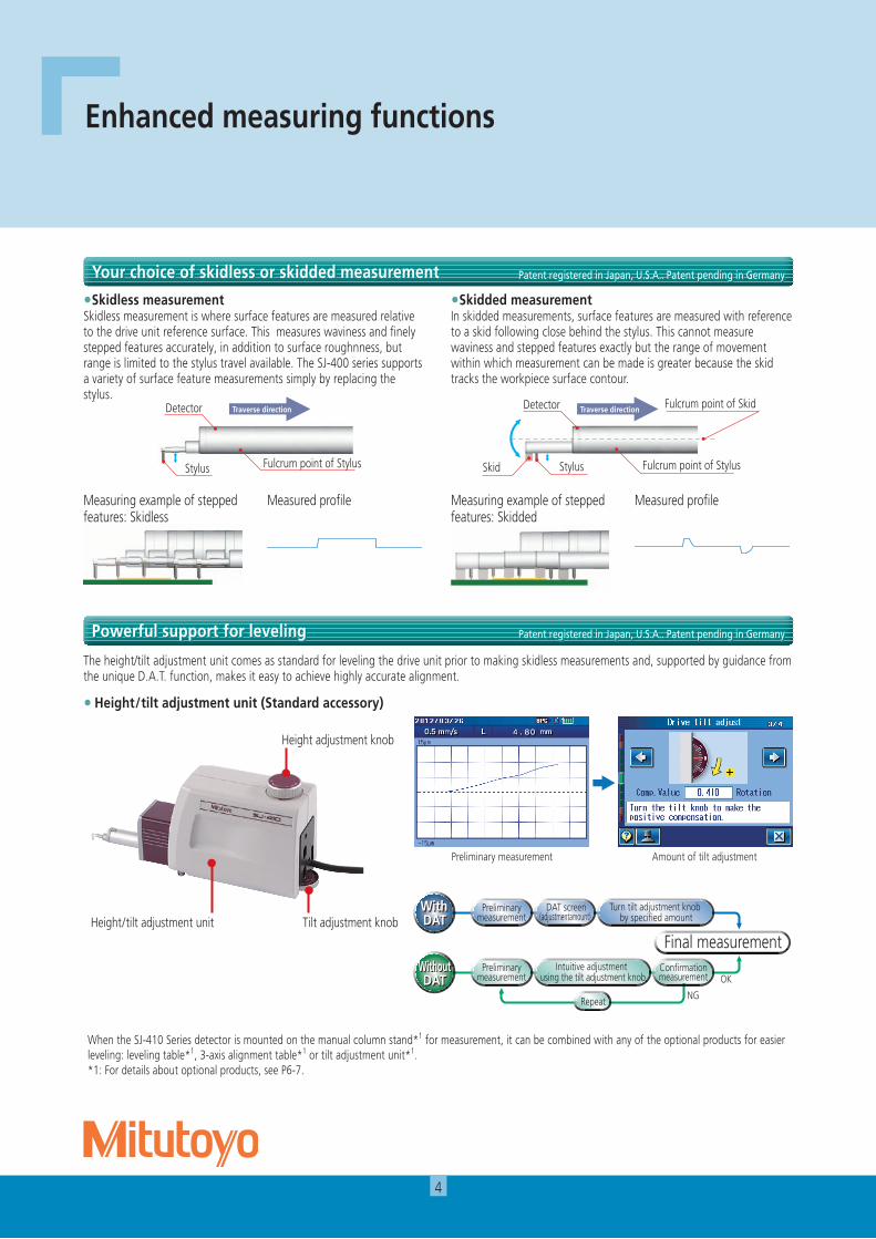
• Height/tilt adjustment unit (Standard accessory)
The height/tilt adjustment unit comes as standard for leveling the drive unit prior to making skidless measurements and, supported by guidance from the unique D.A.T. function, makes it easy to achieve highly accurate alignment.
When the SJ-410 Series detector is mounted on the manual column stand*1 for measurement, it can be combined with any of the optional products for easier leveling: leveling table*1, 3-axis alignment table*1 or tilt adjustment unit*1. *1: For details about optional products, see P6-7.
Preliminary measurement Amount of tilt adjustment
Powerful support for leveling Patent registered in Japan, U.S.A.. Patent pending in Germany
Your choice of skidless or skidded measurement Patent registered in Japan, U.S.A.. Patent pending in Germany
Tilt adjustment knobHeight/tilt adjustment unit
Height adjustment knob
With DAT
With DAT
Preliminarymeasurement
DAT screen(adjustmentamount)
OK
NG
Final measurementPreliminary
measurementIntuitive adjustment
using the tilt adjustment knobWithoutDAT
WithoutDAT
Repeat
Measuring example of stepped features: Skidded
測 定
測定データ
Measured profileMeasured profile
•Skidded measurementIn skidded measurements, surface features are measured with reference to a skid following close behind the stylus. This cannot measure waviness and stepped features exactly but the range of movement within which measurement can be made is greater because the skid tracks the workpiece surface contour.
•Skidless measurementSkidless measurement is where surface features are measured relative to the drive unit reference surface. This measures waviness and finely stepped features accurately, in addition to surface roughnness, but range is limited to the stylus travel available. The SJ-400 series supports a variety of surface feature measurements simply by replacing the stylus.
Fulcrum point of StylusStylus
DetectorTraverse direction
測 定
Fulcrum point of StylusStylusSkid
Detector Fulcrum point of SkidTraverse direction
測 定
Traverse direction
測 定
Traverse direction
測 定
Traverse direction
測 定
Measuring example of stepped features: Skidless

5
Usually, a spherical or cylindrical surface (R-surface) cannot be evaluated, but, by removing the radius with a filter, R-surface data is processed as if taken from a flat surface.
Step
Dimensions
Step volume
Coordinate difference
More measuring functions than expected from a compact tester
R-Surfacecompensation
R-Surfacecompensation
Previously measured data can be recalculated for use in other evaluations by changing the current standard, assessed profile and roughness parameters.
A single measurement enables simultaneous analysis under two different evaluation conditions. A single measurement allows calculation of parameters and analysis of assessed profiles without the need for recalculation after saving data, contributing to higher work efficiency.
Point group data collected for surface roughness evaluation is used to perform simplified contour analysis (step, step height, area and coordinate variation). It assesses minute forms that cannot be assessed by a contour measurer.
This function allows a sampling length to be arbitrarily set in 0.01mm increments (SJ-411: 0.1mm to 25mm, SJ-412: 0.1mm to 50mm). It also allows the SJ-410 series to make both narrow and wide range measurements.
The “OK” symbol means the measurement is within the limits set; “NG” means it is not, in which case an arrow points to either the upper or lower limit in the printout.
An “OK/NG” judgment symbol is displayed when limits are set for the roughness parameter. In case of “NG,” the calculated result is highlighted. The calculated result can also be printed out.
Surface roughness measurement requires a run-up distance before starting the measurement (or retrieving data). When the SJ-410 Series measures, its run-up distance is normally set to 0.5mm. This distance, however, can be shortened to 0.15mm using the narrow part measurement function (starting from the origin point of the drive unit). The function extends the possibility of measurement of narrow locations such as grooves in piston ring / O-ring mounts.
This function samples stylus displacement for a specified time without engaging detector traverse, which enables use as a simplified vibration meter or displacement gage incorporated in another system.
Recalculating Assessing a single measurement result under two different evaluation conditions
Simple contour analysis function
Arbitrary sampling length setting
GO/NG judgement function
Narrow space measuring function Patent pending in Japan
Real sampling
3.5
0.5
0.5 2.5
0.1
Example: surface roughness measuring of piston-ring groove
Example: surface roughness measuring of mounting groove for O-ring
Overruns surface using 0.5mm run-up
Run-up of 0.5mm is not enough for performing the measurement
Evaluation lengthλc=2.5mm1 sampling length
Evaluation lengthλc=0.8mm1 sampling length
2.5
ø1.2
1.3Stylus
Workpiece
Normal run up: 0.5mm
Run up for narrow parts : 0.15mm 1.
8
The run-up distance can be shortened to 0.15mm by measuring from the origin point.
•Narrow space measuring Typical applications
6
Optional Accessories
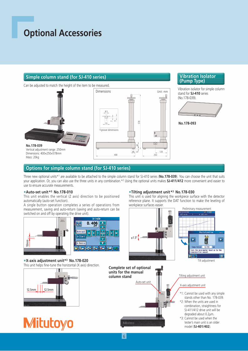
Three new optional units*1 are available to be attached to the simple column stand for SJ-410 series (No.178-039). You can choose the unit that suits your application. Or, you can also use the three units in any combination.*2 Using the optional units makes SJ-411/412 more convenient and easier to use to ensure accurate measurements.
Can be adjusted to match the height of the item to be measured.
Options for simple column stand (for SJ-410 series)
Simple column stand (for SJ-410 series)
12 12040
6057
8
250400
15
8.5
7 11
No.178-039Vertical adjustment range: 250mmDimensions: 400×250×578mmMass: 20kg
*1: Cannot be used with any simple stands other than No. 178-039.
*2: When the units are used in combination, straightness for SJ-411/412 drive unit will be degraded about 0.2µm.
*3: Cannot be used when the tester’s main unit is an older model (SJ-401/402).
•Auto-set unit*3 No.178-010This unit enables the vertical (Z axis) direction to be positioned automatically (auto-set function).A single button operation completes a series of operations from measurement, saving and auto-return (saving and auto-return can be switched on and off by operating the drive unit).
•Tilting adjustment unit*3 No.178-030This unit is used for aligning the workpiece surface with the detector reference plane. It supports the DAT function to make the leveling of workpiece surfaces easier.
•X-axis adjustment unit*3 No.178-020This unit helps fine-tune the horizontal (X axis) direction.
Preliminary measurement
Tilt adjustment
Complete set of optional units for the manual column stand Tilting adjustment unit
X-axis adjustment unitAuto-set unit
10m
m
12.5mm 12.5mm
±1.5°
Dimensions Unit: mm
12 12040
6057
8
250400
15
8.57 11
T-groove dimensions
Vibration isolator for simple column stand for SJ-410 series (No.178-039).
No.178-093
Vibration Isolator (Pump Type)
7
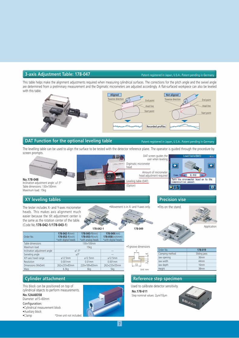
The tester includes X- and Y-axes micrometer heads. This makes axis alignment much easier because the tilt adjustment center is the same as the rotation center of the table.(Code No.178-042-1/178-043-1)
This table helps make the alignment adjustments required when measuring cylindrical surfaces. The corrections for the pitch angle and the swivel angle are determined from a preliminary measurement and the Digimatic micrometers are adjusted accordingly. A flat-surfaced workpiece can also be leveled with this table.
The levelling table can be used to align the surface to be tested with the detector reference plane. The operator is guided through the procedure by screen prompts.
XY leveling tables Precision vise
Cylinder attachment Reference step specimen
3-axis Adjustment Table: 178-047 Patent registered in Japan, U.S.A.. Patent pending in Germany
DAT Function for the optional leveling table Patent registered in Japan, U.S.A.. Patent pending in Germany
Aligned Not aligned
Axial line
End point
Axial line
End point
Start pointStart point
Recorded profiles
Traverse directionTraverse direction
DAT screen guides the user when leveling
Digimatic micrometer head
Amount of micrometer head adjustment required
Leveling table (DAT)(Option)
No.178-048Inclination adjustment angle: ±1.5°Table dimensions: 130×100mmMaximum load: 15kg
7
43
13
•Fits on the stand.
This block can be positioned on top of cylindrical objects to perform measurements.No.12AAB358Diameter: ø15~60mmConfiguration:•Cylindrical measurement block•Auxiliary block•Clamp
Used to calibrate detector sensitivity. No.178-611 Step nominal values: 2µm/10µm
•T-groove dimensions
•Movement is in X- and Y-axes only.
Order No. 178-042-1(mm) 178-052-1(inch)*with digital heads
178-043-1(mm) 178-053-1(inch)*with analog heads
178-049(mm) 178-058(inch/mm)*with digital heads
Table dimensions 130×100mmMaximum load 15kgInclination adjustment angle ±1.5° —Swiveling angle ±3° —X/Y-axis travel range ±12.5mm ±12.5mm ±12.5mmResolution 0.001mm 0.01mm 0.001mmDimensions (WxDxH) 262×233×83mm 220×189×83mm 262×233×55mmMass 6.3kg 6kg 5kg
Order No. 178-019Clamping method Sliding jawsJaw opening 36mmJaw width 44mmJaw depth 16mmHeight 38mm
Application178-042-1 178-049
Unit: mm
*Drive unit not included.

8
Optional Accessories: Detectors / Styli
Standard stylus 12AAE882(1μm)*1
12AAE924(1μm)12AAC731(2μm)*1
12AAB403(5μm)12AAB415(10μm)12AAE883(250μm)*4
( ): Tip radius
Double-length for deep hole *2
12AAE898(2μm)*1
12AAE914(5μm)( ): Tip radius
For small hole12AAC732(2μm)*1
12AAB404(5μm)12AAB416(10μm)( ): Tip radius
For small hole / Double-length for deep hole *2
12AAE892(2μm)*1
12AAE908(5μm)( ): Tip radius
For extra-small hole12AAC733(2μm)*1
12AAB405(5μm)12AAB417(10μm)( ): Tip radius
For small hole *2 *4
12AAE884(φ1.6mm)( ): Tip radius
For ultra-small hole12AAC734(2μm)*1
12AAB406(5μm)12AAB418(10μm)( ): Tip radius
For ultra-small hole *4
12AAJ662(φ0.5mm)( ): Tip radius
For deep hole (double-length and triple-length) *2 For small slotted hole *2
12AAE938(2μm)*1
12AAE940(5μm)( ): Tip radius
2X stylus12AAC740(2μm)*1
12AAB413(5μm)12AAB425(10μm)( ): Tip radius
3X stylus12AAC741(2μm)*1
12AAB414(5μm)12AAB426(10μm)( ): Tip radius
*1: Tip angle 60° *2: For downward-facing measurement only.
小穴用
Colorcoding*3
Detail-A
0.6
0.4
1.6 φ0.6
90°
(S=5/1)
φ2.
415
φ1.
2
3.4
2.4
1.6
0.6 37.744.4
A
極細穴用
Colorcoding*3
Detail-A
0.4
1.2
φ0.3
90°
(S=5/1)
φ2.
48.9
φ0.
6
2.5
37.7
1.2
44.2
A
超小穴用
Colorcoding*3
Detail-A
φ0.3
90°
0.8
0.4
(S=5/1)
φ2.
4
37.7
2.5
φ0.
6
8.9
44.2
0.8
A
深穴用
Colorcoding*3
Colorcoding*3
Detail-A Detail-A
φ2.
4
87.70.9
φ1.290°
94.7
7.6
5.2
A
φ2.
4
137.70.9
7.6
144.7
φ1.290°
5.2
A
深穴2倍用
31.
80.
6
φ2.
4
94.787.70.9
小穴用・深穴2倍
φ1.
2
1.6
3.4
2.4
φ2.
4
94.487.70.6
30
A
0.6
φ0.6
Detail-A
細穴形状用
φ1.
2
φ2.
4
Ball φ1.6
4187.7
93.8
極細穴形状用
φ2.
4φ0.
3
A
7
37.743.8
7
Ball φ0.5
Detail-A
φ2.
4
43.837.7
8.5
3.1
A
φ0.
3Ball φ0.5
Detail-A
細長穴用
φ0.
3
0.4
1.6
φ1.
2
φ2.
4
94.487.70.6
45
A
φ0.6
0.6
Detail-A
*3 : Tip radius 1μm 2μm 5μm 10μm 250μmColor coding White Black No color Yellow No notch or color
*4 : Used for calibration, a standard step gauge (No.178-611, option) is also required
標準スタイラス
90°
0.9 37.7
7.6
44.7
φ2.
4
φ1.2
5.2
A
Colorcoding*3
Detail-A
Detectors Unit: mm Extension rods
Styli Unit: mm
1460
φ8
φ14
Detector
φ14
φ7
1011.53.1
3.6
1.3
Skidless nosepiece(12AAB355)
4
Order No. Measuring force178-396-2 0.75mN ’97ISO and ’01JIS compliant detectors
178-397-2 4mN Detectors that comply with previous standards, for general use, etc.
• 12AAG202 Extension rod 50mm
• 12AAG203 Extension rod 100mm
* No more than one extension rod can be connected.
9
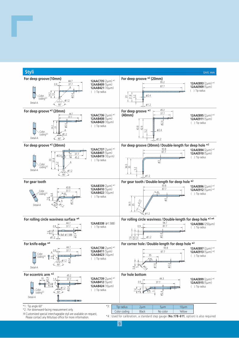
For deep groove (10mm)12AAC735(2μm)*1
12AAB409(5μm)12AAB421(10μm)( ): Tip radius
For deep groove *2 (20mm)12AAE893(2μm)*1
12AAE909(5μm)( ): Tip radius
For deep groove *2 (20mm) 12AAC736(2μm)*1
12AAB408(5μm)12AAB420(10μm)( ): Tip radius
For deep groove *2
(40mm) 12AAE895(2μm)*1
12AAE911(5μm)( ): Tip radius
For deep groove *2 (30mm) 12AAC737(2μm)*1
12AAB407(5μm)12AAB419(10μm)( ): Tip radius
For deep groove (30mm) / Double-length for deep hole *2
12AAE894(2μm)*1
12AAE910(5μm)( ): Tip radius
For gear tooth12AAB339(2μm)*1
12AAB410(5μm)12AAB422(10μm)( ): Tip radius
For gear tooth / Double-length for deep hole *2
12AAE896(2μm)*1
12AAE912(5μm)*1
( ): Tip radius
For rolling circle waviness surface *4
12AAB338(φ1.588)( ): Tip radius
For rolling circle waviness / Double-length for deep hole *2 *4
12AAE886(250μm)( ): Tip radius
For knife-edge *4 12AAC738(2μm)*1
12AAB411(5μm)12AAB423(10μm)( ): Tip radius
For corner hole / Double-length for deep hole *2
12AAE897(2μm)*1
12AAE913(5μm)*2
( ): Tip radius
For eccentric arm *2
12AAC739(2μm)*1
12AAB412(5μm)12AAB424(10μm)( ): Tip radius
For hole bottom12AAE899(2μm)*1
12AAE915(5μm)( ): Tip radius
*1: Tip angle 60° *2: For downward-facing measurement only.※Customized special interchageable styli are available on request, Please contact any Mitutoyo office for more information.
90°
13
φ2.
4
0.9
φ1.2
14.2
37.744.7
A
Colorcoding*3
Detail-A
深溝用(10mm)
23
0.9
φ2.
4
24.2
φ1.2
90°
37.744.7
A識別色
A部詳細
Colorcoding*3
Detail-A 90°
23 φ2.
4
φ1.2
24.2
37.744.7
A
深溝用(20mm)
33 31.8
5.2
φ1.2
A
φ2.4
φ2.
4
90°
37.745.2
Colorcoding*3
Detail-A
深溝用(30mm)
60°
60°
7.6
6.4
37.743.8
φ1.2 φ2.
4A
Colorcoding*3
Detail-A
歯面用
7.6
φ2.
4
φ1.2
0.9 37.744.7
Ball φ1.588
5.2
転がり円うねり用
7.6
φ2.
4φ1.290°
37.70.944.7
AColorcoding*3
Detail-A
ナイフエッジ用
A37.70.9
90°φ1.2
45.2
7.6
10
φ2.
4
φ2.
4
識別色
A部詳細
Colorcoding*3
Detail-A
心違い用
90° φ2.
4φ1.2
45.21.4 37.7
7.6φ
2.410
A
*3 : Tip radius 2μm 5μm 10μmColor coding Black No color Yellow
*4 : Used for calibration, a standard step gauge (No.178-611, option) is also required
23 21.8 5.2
95.2
87.7
φ2.4
φ1.2
深溝用2倍(20mm)
43.8
42.6
5.2
φ2.
4
45.237.7
φ2.4
φ1.2
深溝用(40mm)
36.5
35
5.2
φ3
93.887.7
φ1.2
深溝用(30mm)深穴2倍
36.5
35
φ3
93.8
6.77
87.7
φ1.2
60°
歯面用深穴2倍
94.70.9 87.7
φ1.2 φ2.
4
5.2
6.4
7.6
転がり円うねり・深穴2倍
93.887.7
35
φ0.8
45°
5.8 5 φ1.
6
φ2.
4
穴測定コーナー用・深穴2倍
穴底用
7.4 φ
1
0.5
56.2
φ2.
4
44.337.7
Styli Unit: mm
10
Optional Accessories: For External Output
FORMTRACEPAK-APSJ-410
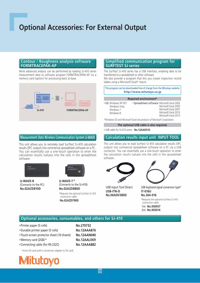
• OS: Windows XP-SP3 Windows Vista Windows 7 Windows 8
• Spreadsheet software: Microsoft Excel 2002 Microsoft Excel 2003 Microsoft Excel 2007 Microsoft Excel 2010 Microsoft Excel 2013
Required environment*
This program can be downloaded free of charge from the Mitutoyo website.http://www.mitutoyo.co.jp
The optional USB cable is also required.
• USB cable for SJ-410 series No.12AAD510
*Windows OS and Microsoft Excel are products of Microsoft Corporation.
• Printer paper (5 rolls) No.270732• Durable printer paper (5 rolls) No.12AAA876• Touch-screen protector sheet (10 sheets) No.12AAN040• Memory card (2GB) * No.12AAL069• Connecting cable (for RS-232C) No.12AAA882
* micro SD card (with a conversion adapter to SD card)
Contour / Roughness analysis software FORMTRACEPAK-AP
Simplified communication program for SURFTEST SJ series
More advanced analysis can be performed by loading SJ-410 series measurement data to software program FORMTRACEPAK-AP via a memory card (option) for processing back at base.
The Surftest SJ-410 series has a USB interface, enabling data to be transferred to a spreadsheet or other software. We also provide a program that lets you create inspection record tables using a Microsoft Excel* macro.
This unit allows you to load Surftest SJ-410 calculation results (SPC output) into commercial spreadsheet software on a PC via a USB connector. You can essentially use a one-touch operation to enter the calculation results (values) into the cells in the spreadsheet software.
USB keyboard signal conversion type*IT-016U No.264-016* Requires the optional Surftest SJ-410
connection cable.
1m: No.936937 2m: No.965014
USB Input Tool DirectUSB-ITN-D No.06ADV380D
Calculation results input unit INPUT TOOL
This unit allows you to remotely load Surftest SJ-410 calculation results (SPC output) into commercial spreadsheet software on a PC.You can essentially use a one-touch operation to enter the calculation results (values) into the cells in the spreadsheet software.
Measurement Data Wireless Communication System U-WAVE
U-WAVE-T *(Connects to the SJ-410)No.02AZD880D * Requires the optional Surftest SJ-410
connection cable.
No.02AZD790D
U-WAVE-R (Connects to the PC)No.02AZD810D
Optional accessories, consumables, and others for SJ-410

11
Specifications
Model No. SJ-411 SJ-412
Order No. mm 178-580-01 178-580-02 178-582-01 178-582-02inch/mm 178-581-01 178-581-02 178-583-01 178-583-02
Measuringrange
X axis 25mm (1inch) 50mm (2inch)
Z1 axis (detector unit) 800µm, 80µm, 8µm*Up to 2,400µm with an optional stylus
Detector
Measuring principle Differential inductance
Resolution 0.01µm (800µm range) / 0.001µm (80µm range) / 0.0001µm (8µm range) 0.4µinch (32000µinch) / 0.04µinch (3200µinch) / 0.004µinch (320µinch)
Stylus tip 60°/2µm (80µinch) 90°/5µm (200µinch) 60°/2µm (80µinch) 90°/5µm (200µinch)Measuring force 0.75mN 4mN 0.75mN 4mNRadius of skid curvature R40 mm (R1.57")Measuring method Skidded measurement / skidless measurement
Drive unit: X-axisMeasuring speed 0.05 , 0.1 , 0.2 , 0.5 , 1.0mm/s (0.002, 0.004, 0.02, 0.04 inch/s)Drive speed 0.5 , 1, 2, 5mm/s (0.02, 0.04, 0.08, 0.2 inch/s)Straightness 0.3µm / 25mm (12µinch/ 1inch) 0.5µm / 50mm (20µinch/ 2inch)
Height-tilt adjustment unit
Height adjustment 10mm (0.39inch)Tilt adjustment ±1.5°
Standards JIS1982 / JIS1994 / JIS2001 / ISO1997 / ANSI / VDA
Parameters Ra, Rq, Rz, Ry, Rp, Rv, Rt, R3z, Rsk, Rku, Rc, RPc, RSm, Rmax*1, Rz1max*2, S, HSC, RzJIS*3, Rppi, RΔa, RΔq, Rlr, Rmr, Rmr(c), Rσc, Rk, Rpk, Rvk, Mr1, Mr2, A1, A2, Vo, λa, λq, Lo, Rpm, tp*4, Htp*4, R, Rx, AR, W, AW, Wx, Wte, Possible Customize
Measured profiles Primary, Roughness, DF, Filtered waviness curve, R-Motif, W-MotifGraph analysis BAC and ADC curvesData compensation Parabola/ Hyperbola/ Ellipse/ Circle/ Conic/ Tilting, Compensation offFilter 2CR, PC75, Gaussian filter
Cut-off lengthλc 0.08 , 0.25 , 0.8 , 2.5 , 8.0mmλs *5 2.5, 8.0, 25mm (100, 320, 1000µinch)
Sample length 0.08 , 0.25 , 0.8 , 2.5 , 8.0 , 25.0mmNumber of sampling lengths ×1, ×2, ×3, ×4, ×5, ×6, ×7, ×8, ×9, ×10, ×11, ×12, ×13, ×14, ×15, ×16, ×17, ×18, ×19, ×20Arbitrary length 0.1~25mm 0.1~50mm
Functions
Customization Desired parameters can be selected for calculation and displaySimple contour analysis function Step, Step volume, Dimensions, Coordinate differenceDAT function Helps to adjust leveling during skidless measurementReal sampling function Samples stylus displacement for a specified time without engaging detector traverse.
Statistical processing Static measurement (max. 3 parameters) is possible. Static processing for MAX, MIN, AVERAGE, standard deviation, histogram and pass rate is possible
GO/ NG judgement*6 Max rule / 16% rule / Average rule / Standard deviation (1σ, 2σ, 3σ)Storage functions 10 measuring conditions can be stored in internal memory
Printing function Measurement conditions / Calculation results / GO / NG judgement result / Calculation results for each sampling length / Measurement curve / BAC / ADC / Environmental setting information
Display languages Japanese, English, German, French, Italian, Spanish, Portuguese, Korean, Traditional Chinese, Simplified Chinese, Czech, Polish, Hungarian Turkish, Swedish, Dutch
Storage Internal memory: Measurement condition (10 sets)
Memory card (option): 500 measurement condition, 10000 measuring data, 10000 text data, 500 statistic data, 1 backup of machine setting, the last ten traces (Trace 10)
External I/O USB I/F, Digimatic output, RS-232C I/F, External SW I/F
Power supply BatteryTwo-way power supply: battery (rechargeable Ni-MH battery) and AC adapter
*Charging time: about 4 hours (may vary due to ambient temperature) *Endurance: about 1500 measurements (differs slightly due to use conditions / environment)
Power consumption 50W
Size(W×D×H)
Display unit 275×198×109mm (10.83×4.29×7.80inch)Height adjustment unit 130.9×63×99mm (5.16×2.48×3.90 inch)Drive unit 128×35.8×46.6mm (5.04×1.41×1.83 inch) 154.5×35.8×46.6mm (6.08×1.41×1.83inch)
MassDisplay unit 1.7kgHeight adjustment unit 0.4kgDrive unit 0.6kg 0.64kg
Standard accessories
*1: Only for VDA/ANSI/JIS'82 standards. *2: Only for JIS'97 standard. *3: Only for JIS'01 standard. *4: Only for ANSI standard. *5: λs may not be switchable depending on standard selected. *6: Standard deviation only can be selected in ANSI.16% rule cannot be selected in VDA.*7: Either No.178-396 or No.178-397 is supplied as a standard accessory depending on the Order No. of the main unit for SJ-410 Series.*8: The standard stylus (No.12AAC731 or No.12AAB403), which is compatible with the detector supplied, is a standard accessory. To denote your AC line voltage add the following suffixes (e.g. 178-570-01A). A for 120V, C for 100V, D for 230V, E for 230V (for UK), DC for 220V (for China), K for 220V (for Korea)
Detector*7, Stylus*8
178-601 Roughness specimen (Ra3µm)270732 Printing paper12BAL402 Touch-screen protection sheet
12BAG834 Touch pen12AAN041 Carrying case
AC adapter, Philips screwdriver, Strap for stylus pen, Operation manual, Quick reference manual, Warranty
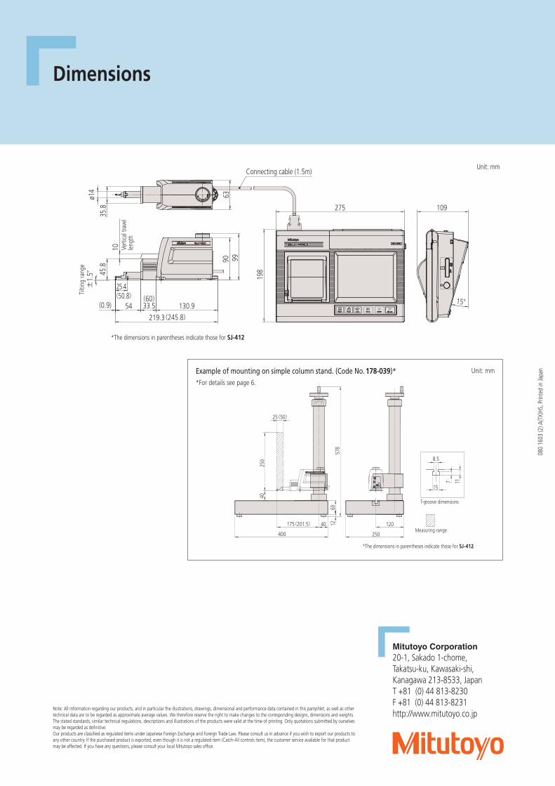
Dimensions±
1.5°
130.9
45.8
90
ø14
35.8
6399
219.3
33.5(0.9)
25.4
54
10
Connecting cable (1.5m)
(50.8) (60)
(245.8)
Tilti
ng ra
nge
Verti
cal t
rave
l len
gth
*The dimensions in parentheses indicate those for SJ-412
15°
198
109275
Example of mounting on simple column stand. (Code No. 178-039)**For details see page 6.
12
250
25(50)
12040
6057
8
175(201.5)
40
250400
Code No.178-039 簡易スタ ンド外観寸法図
*The dimensions in parentheses indicate those for SJ-412
Measuring range
15
8.5
7 11
T-groove dimensions
Unit: mm
Unit: mm
080
1603
(2) A
(TX)
HS, P
rinte
d in
Japa
n
Mitutoyo Corporation20-1, Sakado 1-chome,Takatsu-ku, Kawasaki-shi,Kanagawa 213-8533, JapanT +81 (0) 44 813-8230F +81 (0) 44 813-8231http://www.mitutoyo.co.jp
Note: All information regarding our products, and in particular the illustrations, drawings, dimensional and performance data contained in this pamphlet, as well as other technical data are to be regarded as approximate average values. We therefore reserve the right to make changes to the corresponding designs, dimensions and weights. The stated standards, similar technical regulations, descriptions and illustrations of the products were valid at the time of printing. Only quotations submitted by ourselves may be regarded as definitive.Our products are classified as regulated items under Japanese Foreign Exchange and Foreign Trade Law. Please consult us in advance if you wish to export our products to any other country. If the purchased product is exported, even though it is not a regulated item (Catch-All controls item), the customer service available for that product may be affected. If you have any questions, please consult your local Mitutoyo sales office.
Export permission by the Japanese government may be required for exporting our products according to the Foreign Exchange and Foreign Trade Law. Please consult our sales office near you before you export our products or you offer technical information to a nonresident.