Embed Size (px)
Citation preview

1
“BIG BEN”
The Design and Construction of the
Great Clock of the Palace of Westminster
by
M S Loveday B.Sc., C.Eng., MIM, M.Inst P.
C G McKay B.Sc., C.Eng., MIEE

2
Introduction
This paper was initially presented at the conference “Big Ben- Its Engineering Past and Future” organised in 1980 by the Institution of Mechanical Engineers and subsequently published in a book of the same name in 1981. The article was to acquaint the reader with the historical background to the design and building of the Great Clock of the Palace of Westminster so that the detailed scientific investigation into the cause of failure, in August 1976, of the quarter chiming mechanism subsequently discussed, may be more readily understood and appreciated.
Standing as a paper in its own right, it now serves to inform those interested in the history of the Great Clock.
Some alterations have been made to improve on the initial editorial method and constraints in the availability of illustrations.
Remastered by Chris McKay October [email protected]
Copyright © 1980 C.G. McKay & M.S. Loveday

3
“BIG BEN”
The Design and Construction of the
Great Clock of the Palace of Westminster
by
M S Loveday B.Sc., C.Eng., MIM, M.Inst P.
C G McKay B.Sc., C.Eng., MIEE

4
Figure 1. Charles Barry’s design for the Clock Tower for the New Palace of Westminster.

5
Historical Background
On the night of October 16th, 1834, Mr Charles Barry, the architect of St Peters Church, Brighton, was returning from that seaside resort when a red glare on the London side of the horizon showed that a great fire had begun. Eager questions elicited the news that the Houses of Parliament had caught fire and all attempts to stop the conflagration were unavailing. No sooner had the coach reached London than Barry hurried to the spot and remained there all night, along with seemingly the rest of the population of the metropolis, all absorbed in the grandeur and terror of the sight.
The fire was started because un-required wooden tallies, which were used as Treasury receipts prior to 1812 were being burned in the central boiler instead of the usual coke. The stokers over-stocked their boiler and left their duty early hoping that their fire would last the night! It was unfortunate that an overheated flue set fire to the whole building.
Following the conflagration, Sir R. Smirke was directed to prepare designs for a replacement building. However, the Government of the day was called upon in a published letter from Sir E. Cust and Sir R. Peel to open a competition for the design and to appoint a Royal Commission to award the prizes. A committee of the House of Lords in June 1835 subsequently recommended the terms of the competition. The style of the building was to be “Gothic or Elizabethan” and the result of the competition to be announced before the 20th January 1836. Four prizes were promised, each of £500, it being understood that the winner of the first prize should carry out the rebuilding work, unless some grave course to the contrary be discovered, in which case the winner was to receive an additional prize of £1000. Charles Barry submitted his design for a building in the gothic style during December 1835, and was one of 97 competitors. It was announced on February 19th 1836 that Barry had won the competition.
In his design Barry had planned an imposing clock tower and the then Chief Lord of the Woods and Forests promised “A noble clock, indeed a King of Clocks, the biggest the world has ever seen, within sight and sound of the throbbing ear of London”; Figure 1.
This clock would not be the first public clock to adorn the Palace of Westminster, since as early as 1290 King Edward I directed that a tower be erected containing a clock and a bell on which the hour could be struck, the bell being known as “Great Tom of Westminster”.
In 1699, William III gave “Great Tom” to the new cathedral of St Pauls, however the bell was broken during transportation and was recast several times by various founders until Richard Phelps of the Whitechapel foundry finally cast a satisfactory bell in 1716.
The Westminster Clock Tower became unsafe and in 1707, Queen Anne decreed that it should be demolished and the proceeds from the sale of the materials should be given to the poor of the parish of St Margarets, Westminster.
The first vote of public money for the new building was made on 3rd July, 1837 and work on the coffer dam for the river wall embankment started soon after and was completed in 1839. The first stones of the building itself were laid privately by Charles Barry’s wife, Sarah on 27th April 1840.
The supervision of the building was not left entirely in the hands of the architect, but were under the control of a Commission appointed by Parliament. Other architects felt that such an arrangement would undermine the professional status of architects as a body, and thus censured Barry for not protesting and agreeing to work under such a committee. Likewise certain technical matters connected with the building such as the heating and ventilating system and the design of the clock and bells were also not entirely in Barry’s hands. Although Barry’s original design for the building included a clock tower, it was also to serve the

6
Figu
re 2
. Fr
ont e
leva
tion
of th
e G
reat
Clo
ck d
ated
Jan
uary
185
2.N
ote
flys
behi
nd th
e cl
ock.

7
dual purpose, along with the other towers, of providing a ventilating shaft for the heating system. Thus the interior of the clock tower was not completely under the control of Barry and against the architect’s wishes part of the clock tower was used as a smoke flue, with the outlets being just below the clock dials, thus restricting the open shaft for the clock weights to a width of 2.6M (8’ 6”). It is perhaps surprising to note that it was originally intended that approximately one third of the entire new building was to be used solely for the purpose of heating and ventilating.
Charles Barry knew little of clocks and bells and was thus going to rely on the Queen’s Clockmaker, Benjamin Lewis Vulliamy for the design of the clock. Thus in March 1844, with the agreement of the Board of Works, Barry wrote to Vulliamy and asked him to prepare plans and a specification for a clock to show the time on four dials, each 30 feet in diameter, and to strike the hour on a bell weighing 8-10 tons and, if practical, to chime the quarters on eight bells. Vulliamy replied in April 1844 and agreed to furnish suitable plans for the sum of 100 guineas if he were chosen to manufacture the clock, and a further 100 guineas if some other maker were chosen. Figure 3. B.L. Vulliamy was rather slow to act at his appointed task and by July 1846 Her Majesty’s Commissioners of Woods and Forests had clearly had second thoughts of the wisdom of entrusting the task of the design of the clock to a single maker, particularly since they had been pressed by another maker E.J. Dent, for the privilege of constructing the clock. Dent had written to the Commissioners in November 1845, seeking to be included amongst the manufacturers who would be asked to tender for the clock, but further expressed the opinion in December 1845 that he would not wish to manufacture a clock designed by another maker but would be quite happy to construct a timepiece to meet the specification drawn up by the Astronomer Royal, Sir G. B. Airy.
Figure 3. Benjamin Lewis Vulliamy’s design for the Great Clock for the New Palace of Westminster.
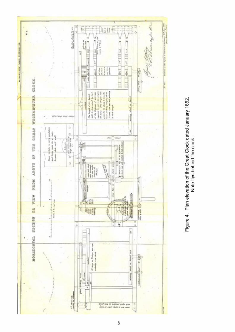
8
Figu
re 4
. P
lan
elev
atio
n of
the
Gre
at C
lock
dat
ed J
anua
ry 1
852.
Not
e fly
s be
hind
the
cloc
k.

9
Thus Airy was approached by the Commissioners and duly produced a specification for the clock dated 22nd June 1846 and three makers, Vulliamy, Dent and Whitehurst were each invited to submit details of a suitable clock to meet the new specifications and to give an estimate of the cost of constructing such a clock. Sir G. B. Airy’s original specification may be seen in the accompanying inset.
The Specification
CONDITIONS TO BE OBSERVED IN REGARD TO THE CONSTRUCTION OF THE CLOCK THE NEW PALACE OF WESTMINSTER
I. Relating to the Workmanlike Construction of the Clock.1 The clock-frame is to be of cast-iron, and of ample strength. Its parts are to be firmly bolted together. Where there are broad bearing surfaces, these surfaces are to be planed.
2. The wheels are to be of hard bell metal, with steel spindles working in bell-metal bearings, and proper holes for oiling the bearings. The teeth of the wheels are to be cut to form on the epicycloidal principle.
3. The wheels are to be so arranged that any one can be taken out without disturbing the others.
4. The pendulum pallets are to be jewelled. II. Relating to the accurate going of the Clock.5. The escapement is to be dead-beat, or something equally accurate, the recoil escapement being expressly excluded.
6. The pendulum is to be compensated.
7. The train of wheels is to have a remontoir action, so constructed as. not to interfere with the dead-beat principle of the escapement.
8. The clock is to have a going fusee.
9. It will be considered an advantage if the external minute hand has a discernible motion at certain definite seconds of time.
10. A Spring apparatus is to be attached for accelerating the pendulum at pleasure during a few vibrations.
11. The striking machinery is to be so arranged that the first blow for each hour shall be accurate to a second of time. III. Relating to the possible Galvanic Connexion with Greenwich.12. The striking detent is to have such parts that, whenever need shall arise, one of the two following plans may be adopted, (as, after consultation with Mr. Wheatstone or other competent authorities, shall be judged best;) either that the warning movement may make contact, and the striking movement break contact, for a battery, or that the striking movement may produce a magneto-electric current.
13. Apparatus shall be provided which will enable the attendant to shift the connection by means of the clock action, successively to different wires of different hours, in case it should hereafter be thought desirable to convey the indications of the clock to several different places.

10
Figu
re 5
. Fr
ont e
leva
tion
of th
e G
reat
Clo
ck d
ated
Mar
ch 1
852.
Not
e th
e fly
s ar
e no
w v
ertic
al d
riven
by
beve
l gea
rs..

11
IV. General Reference to the Astronomer Royal.14. The plans, before commencing the work when completed, are to be subjected to the approval of the Astronomer Royal.
15. In regard to the Articles 5 to 11, the maker is recommended to study the construction of the Royal Exchange clock.
(signed) G.B. Airy 22 June 1846.
The choice of three makers to submit quotations for manufacture of the clock would seem to be a traditional civil service procedure which in general is still followed today; the names of suitable makers being suggested by Sir G.B. Airy.
Airy clearly favoured E. J. Dent, with whom he had worked with before on building a clock for the Royal Exchange in 1843 - 1844. Airy expressed the view that if Dent’s price for the Westminster Clock should not be excessive then the Commissioners should employ Dent without inquiry of other workers. However, if it appeared objectionable then Vulliamy and Whitehurst should also be approached. Airy regarded Vulliamy as “A maker of some celebrity, but said to be unmanageable in temper and very expensive in prices”, whilst Whitehurst was regarded as “A man of reputation in the North of England, and known as the inventor of the Watchman’s Clock”.
Charles Barry presumably favoured B. L. Vulliamy since he knew the Queen’s Clockmaker both by reputation as the leading clockmaker in the country, and personally he had manufactured clocks for a number of churches and houses of which Barry was the architect.
B. L. Vulliamy refused to submit an estimate for a clock to be manufactured under the immediate and sole direction of Airy, on the grounds that there were other individuals certainly as well, if not better qualified to offer opinions on the subject who could act as referees conjointly with the Astronomer Royal, and secondly because Airy had clearly shown himself to be strongly prejudiced in favour of E.J. Dent. Nevertheless, in August 1846, B.L. Vulliamy supplied the specification and plans for a clock as originally requested in 1844. In addition Vulliamy also forwarded his comments on Airy’s specification for the clock which clearly showed that Airy’s grasp of the design and construction of turret clocks was rather limited and thus Vulliamy’s objection to Airy as the sole referee was fully justified. Indeed when Airy’s specification for the clock became public knowledge many manufacturers expressed the view that no such clock could be manufactured, and in particular the requirement that the first blow struck on the hour bell should be correct to within one second was an impossibility.
Airy’s comments dated 18th May 1847 on Vulliamy’s plans for the clock also suggest that satisfactory working relationship would never have been established between the two parties; “I have very carefully examined Mr. Vulliamy’s beautiful plans. In regard to the provisions for strength, solidity, power and general largeness of dimensions, they are excellent. In regard to delicacy they fail; and they fail so much, that I think myself justified in saying that such a clock would be a village clock of very superior character, but would not have the accuracy of an astronomical clock”.
On 15th March 1847 John Whitehurst and Edward J. Dent duly submitted estimates of £3,523 and £1,600 respectively, prices which also covered the electro-mechanical mechanism for transmitting a time pulse to Greenwich.
In commenting on the tenders, Airy states: “If it were necessary to entrust the making of the clock, without any control, to one or other of these two makers, I should prefer Mr Dent; because I think it easier for Mr
12
Dent to acquire Mr Whitehurst’s solidity, than for Mr Whitehurst to acquire Mr Dent’s accuracy. But under the most trifling control either of these makers will certainly construct the clock in a perfectly satisfactory way”. On the question of the significant different in the price quoted by the two makers, Airy observed “Mr Whitehurst has made his estimate at what may be called a ‘paying price’ while Mr Dent, who is one of the most enterprising of London tradesmen, has not improbably been willing to construct the clock at an actual loss to himself, for the sake of the reputation which he hopes thereby to acquire”.
Although Vulliamy formally refused to quote a price for the construction of the clock, six years later he gave an indication of the price that he would have charged in a letter to the Office of Works. “I will take this opportunity to express an opinion on the subject of the cost of the proposed clock; I have no hesitation in saying that the cost of this clock ought to be the secondary consideration only, and its excellence the primary; and that whether it cost £1,000 more of less is perfectly immaterial, provided the money is properly spent. It is barely within the range of probability that such a clock will ever again be required; it is a first and last expense, and consequently a very different case from one of frequent recurrence. At the time Mr Whitehurst and Mr Dent furnished their estimates, I for my own satisfaction made out a general statement of the probable expense of making and fixing the clock, which I calculated would amount to about £3,500”. Obviously Vulliamy could not have foreseen that 123 years later an accident occurred which would necessitate rebuilding a major part of the clock.
For some unknown reason the Commissioners procrastinated and no decision was made to award the contract to either Dent or Whitehurst for the manufacture of their proposed clock, and virtually five years elapsed before a contract was finally placed, with E.J. Dent. In the meantime, the tower which was started in 1843 had reached a height of 46 M (150 feet) above ground by about l851.
The name of the accredited designer of the present clock, E.B. Denison, first appears in the parliamentary papers relating to the clock in 1849. E.B. Denison, as an amateur horologist was rapidly becoming recognised as an authority on clocks and bells, and the first edition of his Treatise on the subject was published in London by Virtues in 1850. In 1851, Lord Seymour, then First Commissioner of Works, invited Mr Denison to act with the Astronomer Royal in advising the course of action to be taken concerning the new clock for the Houses of Parliament, and the matter once again started to make progress.
It is clear right from the outset that Denison was in agreement with Airy that Dent was the only manufacturer capable of making the clock. In January 1852 Airy and Denison wrote to Lord Seymour enclosing a revised specification for the clock together with two drawings showing a plan and side elevation of the movement, drawn by Denison which are now held in an Archive of the Royal Observatory, Hurstmonceaux Castle, Figures 4, 5.
This time only Dent was invited to revise his previous quotation in accordance with the revised specification and he was subsequently instructed on 25th February 1852 to manufacture the clock within two years for the agreed sum of £1,800. It should be noted that the two drawings, shown in Figures 2 and 4, together with the new short specification which included the requirement for the wheels to be made of cast iron, now superseded the original specification drawn up by Airy six years earlier.
Following the placing of the contract with E.J. Dent, Denison and Airy visited the clock tower with Barry on 22 March 1852 to discover that the building was in such an advanced stage of construction that it was going to be impossible for the clock to occupy the position they had originally contemplated, and on which the contract with Dent had been agreed; at least without incurring enormous expense of pulling down and re-building the internal walls. In defence of Airy and Denison it should be noted that when they drafted their specification for the clock they had been furnished with plans of the building and sections of the tower as it was proposed to build, but they had been given to understand that the internal parts of the building were in such a state that there was to be the opportunity of altering the arrangements so as to suit the clock. It thus became necessary for Airy and Denison to modify their design for the clock to suit the internal walls,

13
and it was subsequently agreed that Dent should be paid a further £100 to accommodate the revisions to the original plan. A sketch of the revised design of the clock from Denison’s notebook dated 31 March 1852, is shown in Figure 5. A crucial alteration in the design pertinent to the subsequent paper relating to failure of the quarter chiming mechanism is that the fly-vanes were placed in vertical arbors above the clock movement instead of being mounted on horizontal arbors immediately behind the clock as originally shown on the plans dated 29 January 1852.
E.J. Dent made good progress with the construction with the movement and before the end of 1852 the going train had been assembled and the pendulum connected and being maintained.
Unfortunately E.J. Dent was not to see the completion of his masterpiece since he died on 8 March 1853. The clock was subsequently completed by E.J. Dent’s stepson, Fredrick William Rippon who changed his name to F.W. Dent on the death of his stepfather. The clock movement was ostensibly completed by 1854 and remained running in Dent’s workshop for five years before being installed in the clock tower.
During the major period of construction of the movement, Airy was abroad and hence the majority of the supervision was solely under Denison’s eye.
Figure 6. The Great Clock on test in Dent’s workshops.

14
SPECIFICATION, with two Drawings of the Great Westminster Clock.
In the accompanying drawings many of the details are omitted. Mr. Dent will understand that some of them are necessarily involved in the construction shown in the drawings. Some other will be determined on further consideration, and on the result of experiments now making by Mr. Dent, especially with regard to the escapement. Mr. Dent must therefore provide in his estimate for having to execute all the details of the clock not shown in these drawings, as well as the whole of the work, according to the requisition of the present Astronomer Royal and Mr. E.B. Denison.
The provisions for electrical apparatus need not be. included in the present estimate; but it is desired that Mr. Dent will include in his present tender the following things, some of which were excluded from his former one:- All the cast iron beams and other iron-work necessary for the clock; weights, dial-work and hammers, assuming the hour bell to weigh 14 tons, and the four quarter bells to correspond, according to the notes required for the Cambridge chimes.
The masons’ work, including any stone corbels to support the clock and works, and the dials themselves, and windows in them, and a passage through the air shaft to allow a man to get to all the dials from the inside, and also to light the clock room, will be provided as part of the building.
The hands are to be of iron, timmed, zinced, and gilt, with external counterpoises (for wind as well as weight) to be painted the colour of the dial, as in Mr. Dent’s exhibition clock; the hands will have to be suitable for four dials of 20 feet in diameter.
All the wheels to be of cast iron, except those in the escapement; the material of the pinions and of the different arbors will be as may be afterwards determined.
Mr. Dent will be alowed, during the construction of the clock, to to use the ground floor of the tower, or the floor next above it, in order to avoid the ascending 165 feet many times a day, or the taking of premises large enough to contain and arrange the works of such a clock.
The pendulum is to bc entirely in the clock-room; and consequently the clock must be about 13 feet from the floor, and a stage or platform must be erected for winding the clock and examining it on bothh sides. The escapement will be enclosed in glass, and the tender must include such boxing of the pendulum and weights in the clock room, or trap-doors for them, as Mr. Airy and Mr. Denison may require.
Having regard to the increase of size over the clock formerly proposed by Mr. Dent, and the other alterations in the plan, and on the other hand, the greater cheapness of cast iron over that of gun metal for the wheels, and some other arrangements; less expensive than those formerly proposed, the Board of Works now desires to know for what increase (if any) upon his former tender, Mr. Dent will now undertake to construct the clock, and within what time; payment not to be required (as before) until the clock has been going for a year, and Mr. Airy and Mr. Denison have certified that the work is properly completed.
We approve of this specification, subject to the adoption by the Board of such provisions as it is herein assumed, will be made by them.
(Signed) G.B. AiryE.B. Denison 29 January 1852.
15
Whitehurst’s Design Details of the clock designed by John Whitehurst of Derby, to meet the specification produced by G. B. Airy in 1846, are given in a letter submitted to the commissioners in September 1846. From Airy’s comments it would appear that Whitehurst’s drawings were not fully detailed plans, and even these had disappeared from the office of works by 1851 [Denison, Rudimentary Treatise p 266].
Whitehurst’s clock was designed to strike the hours upon a bell of 14 tons and to strike three quarters only, and not the forth quarter at the hour. The quarters were to be struck on 5 bells and would thus be distinct from other public clocks in London. The clock was to show the hours and minutes upon four dials, 6.7 m (22 feet) in diameter with copper hands to each dial. Whitehurst is generally credited with the reinvention of the pin wheel dead beat escapement which he proposed for the Westminster clock, with a pendulum compensated with mercury “or any other substance the Astronomer Royal may think fit”. The wheels and bushes were to be made of hard red brass, and the pinions and pellets to be hard, the work to be fitted into a strong iron frame. The great wheels of the striking and quarter trains were to be 0.91 m (3 feet) in diameter, whilst the great wheel of the going train was to be 0.45m (18 inches) in diameter. The striking and quarter parts of the clock were to run four days before re-winding, whilst the going train was to last eight days. Clearly it is impossible to reconstruct Whitehurst’s design from such a description with absolute certainty, however, it is possible that the clock would have been an extended barrel clock similar to that in Bray Church, Berkshire, which was constructed by Whitehurst in 1840. It is also not clear how the clock would have satisfied the criteria that any of the wheels could have been removed without disturbing the others. Whitehurst in returning his tender stated that he had designed his clock without having had the opportunity to study the construction of the Royal Exchange clock despite Airy’s recommendation.
The Failure and Reconstruction It is unnecessary here to give a description of the failure of the quarter chiming train which occurred in August 1976 since the topic is fully covered in the paper that followed this one. See figure 8. However, from the horological view point is it worth briefly to consider certain aspects of the design of the clock which may have affected the failure sequence. It will be shown in the paper by Owen et al that failure was caused by a fatigue fracture at the fly arbor. Denison was well aware of the importance of the fly and of the possible consequence of a failure of the fly. He insisted that considerable care was taken to ensure that the fly ratchet was keyed on to its arbor by machined octagonal flats rather than merely being pinned together. Fly failures on turret clocks are not unknown and are often attributed to the breaking of the click spring which engages the pawl in the fly ratchet. On the Westminster clock Denison incorporated two diametrically opposed clicks on each fly arbor.
Once the fly became disconnected the train would have started to run faster than usual, and the quarter chime bell crank levers which normally operate slowly due to the momentum of the bell hammers, would
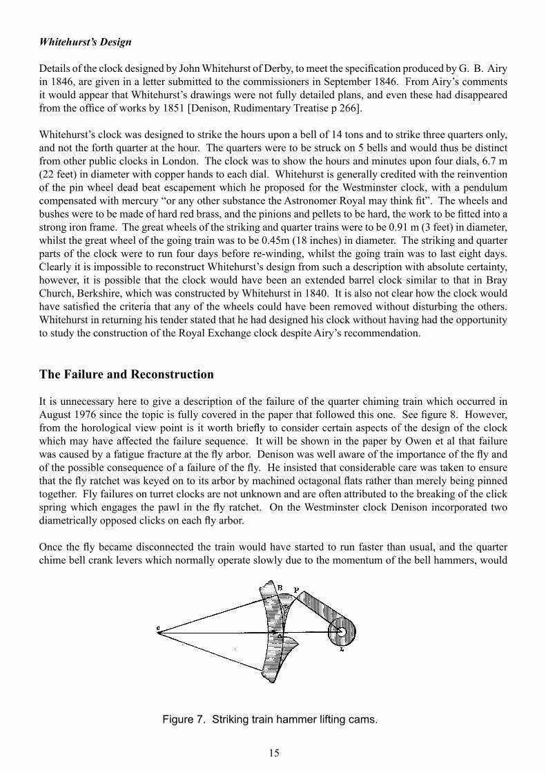
Figure 7. Striking train hammer lifting cams.

16
have started to strike against the rising cams on the drum, rather than falling into “dead space” as carefully allowed in Denison’s design, as shown in Figure 7.
The five levers would have thus imposed severe dynamic impact loading on the frame and mechanism causing three of the levers to snap off. Denison knew of the damage which could be caused by such a sequence of events and noted in his treatise on clocks, page 287, that it was necessary “to prevent the lever dropping on to the cam itself, which shakes the clock most injuriously”.
The likelihood of any other turret clock failing in precisely the same manner as ‘Big Ben’ is very remote, mainly because most other clocks have well supported horizontally mounted fly vanes on solid arbors, nevertheless the importance of regular inspection of critical components, such as click springs, is clearly vital.
The horological fraternity is clearly in debt to all those persons concerned with the restoration of the clock following the accident. That the major undertaking was completed within the relatively short space of time of nine months demonstrates that the British Engineering Profession still maintains the high standards of skill and enterprise set by its Victorian forefathers. The clock was fully restored and the chiming train was set in operation on 4th May 1977 to coincide with the visit of Queen Elizabeth II to the Palace of Westminster as part of the Silver Jubilee celebrations. The credit for the speedy restoration of the clock was largely due to the then Resident Engineer of the Palace of Westminster, John Darwin, knowing how to oil the bureaucratic machinery in order to make the rapid decision to fully restore the clock rather than merely replacing it with a modern synchronous electric motor, and to John Vernon of Thwaites and Reed Ltd who, with his colleagues managed in a very short space of time, to produce drawings of the clock, arrange for patterns to be made, components to be cast and machined and to marry the new quarter chiming mechanism to the existing clock frame such that the join can hardly be seen.
Figure 9. The Great Clock after the disaster..

17
Edmund Beckett Denison, who later became Lord Grimthorpe in 1886, would have been proud to think that his master piece was still held in such high esteem in the heart of the nation that its full restoration was considered of paramount importance.
Acknowledgements and Further Reading Much has been written on the subject of the Great Clock, of its hour bell “Big Ben” and of the principal characters involved in their construction as may be seen in the accompanying bibliography. Students of the subject are fortunate in respect that all of the original correspondence with the Office of Works have been printed as parliamentary papers.
The biographies of Sir Charles Barry by the Rev. A Barry, and of Lord Grimthorpe by F.J. Britten and P. Ferriday all provide useful background information.
Denison’s own account of the clock in his book “A Rudiememtary Treatise on Clocks, Watches and Bells” makes interesting reading, as is one of the most recent and excellent accounts by Dr. Vaudrey Mercer in “Edward John Dent and his Successors”.
Figure 10. The Great Clock after reconstruction..

18
Description of the Movement and Bells
The clock movement itself is housed in a room approximately 55 metres (180 feet) above ground level, behind the four dials. The bells are mounted on an open frame further up the tower, with the 13,700 Kg (13.12 tons) hour bell being in the centre of the four quarter chime bells. Strictly speaking, it is the largest bell which is named ‘Big Ben’; however, the wider use of the title to refer to the clock or the tower is now commonly accepted.
Access to the clock is only gained by ascending the 292 steps of the square spiral staircase, since no provision for a lift was made by the architect.
The clock mechanism is mounted on a frame made of two massive cast iron members some 4.7 metres long by 0.5 metres deep which are held 1.4 metres apart by cross members, the whole frame being rigidly bolted to pillars forming the backbone of the tower which reach right down to ground level.
The movement is a three train flat bed turret clock with the centre going train regulated by Denison’s double three legged gravity escapement connected to a 4.12 metre pendulum. The hour striking train is mounted on the left hand end of the frame, and the Westminster quarter chiming train on the right hand end of the frame, as viewed from the interior of the clock room facing west. The clock frame is not in the centre of the chamber but approximately 0.6 metres away from the west wall, with the pendulum being supported from a rigid bracket mounted in the wall. The movement is driven by three weights which descend the shaft underneath the clock, being 254 Kg on the going train and 1180 Kg on both the chiming and striking trains. It should be noted that all the weights are supported on a loop pulley system and thus the weight actually providing the driving force to each train respectively is only half the values quoted.
A photograph of the clock movement is shown in figure 9. For a fuller account of the precise action of the strike and chime lifting off mechanisms the reader is referred to the books by Denison, Britten or Mercer.
A third shorter girder, parallel to the two main frame members, mounted on cross members supports the front bearings of the going train and so enables the arbors to be shorter than the full frame width, hence allowing the weights of the arbors to be reduced and their rigidity increased. Virtually all the arbors run in plain bearings mounted in plumber blocks bolted to the main frames, thus allowing parts of the movement to be de-mounted with the minimum of trouble.
The leading off work to the dials is mounted above the movement on girders which also support Denison’s ‘double-barrelled crab’, which was purpose built to winch the dismantled clock up the tower. The movement is connected by bevel gears to the leading off work via an angled shaft.
The c1ock was originally wound by hand, some three times a week, taking thirty man hours; however the striking and chiming trains are now electrically wound using the mechanism installed by Dent in 1913.
A distinctive feature of the movement is the two large vertically mounted fly vanes which are connected to the movement by bevel gears at the bottom ends of their supporting arbors, with their upper ends constrained in bearings mounted in the ceiling of the clock room.
The clock we see today evolved over an eight-year period between 1852 and 1860. The design of the movement changed throughout the construction period and major modifications were accommodated. Thus many holes drilled in the cast iron frame were subsequently superfluous and were merely filled with lead and painted over as was the common practice of the day. This flexible design and construct process may partially account for the lack of accurate working drawings of the clock plus the fact that Denison did not seem to hold much favour with mechanical drawing, a view that he later publicly expressed in 1879 on the occasion of the opening of the new building of the Horological Institute of which organisation Denison

19
Figure 10. The Great Clock’s first escapement. A dead beat acting directly on the pendulum.
Figure 11. The four-legged gravity escapement.
Figure 12. Denison’s double three-legged gravity escapement...

20
was President. On that occasion he declared that “mechanical drawing was to be of little or no value to horologists” (Britten, 1905).
The going train of the clock was the subject of most of the design modification; it is known that at least three different types of escapement being employed to maintain the pendulum for varying periods of time, and it has been suggested that a further three types were also considered for use with the clock (Mercer 1977). The first escapement used was a three-legged dead beat type, shown in Figure 10 which was probably used in conjunction with a spring remontoire thus detaching the pendulum from the varying wind forces on the hands.
The second escapement was a four-legged gravity escapement invented by Denison, Figure, of the type used in good quality regular clocks; Figure 11. This in turn was superseded in about 1860 when the clock was installed in the tower, by the most famous of Denison’s inventions, a double three-legged gravity escapement, Figure 12.
Figure 13. The Great Clock from the frontispiece of a Rudimentary Treatise on Clocks Watches & Bells by Edmund Beckett Denison.

21
References
1 Rev. A. Barry, 1867, “Life and works of Sir Charles Barry” Pub. John Murray, London2 Parliamentary Papers No. 500, 18523 Parliamentary Papers No. 436, 18554 Parliamentary Papers No. 553, 18605 E.B. Denison, 1866, “A lecture on large clocks”, Horological Journal, IX? 61-676 E.B. Denison, 1873, “Visit to the Westminster Clock.” Horological Journal, XVI 947 Anonymous. 1875, “Time Map for the Westminster Clock.” Horological Journal, XVIII, 488 E.B. Denison, 1875. “Visit to the Westminster Clock”. Horological Journal, XVIII, 49-559 E.T. Loseby, 1859, “The Westminster Clock”, Mechanics Magazine. 12 August, 10310 ibid 21 October, 26311 F.J. Britten, 1905. “Lord Grimthorpe, Obitbary”. Horological Journal. 47, 142-15012 E.B. Denison, 1903. “A Rudimentary Treatise on Clocks, Watches and Bells for Public Purposes” 8th Edition. Reprinted 1974, E P Publishing Ltd.13 D. de Carle. 1947, “British Time”. 54-79, Pub. Crosby Lockwood & Son. London14 A. Gillgrass, 1946. “The Book of Big Ben”. Pub. Herbert Joseph Ltd. London.15 F.J. Britten, 1920. “The Westminster Clock”. Watch & Clock Makers Handbook (13th Edition). 420-425.16 P. Ferriday, 1957, “Lord Grimthorpe”, Pub. John Murray. London.17 A.W. Hattersley. 1957. “History of Great Clock & Bells,” - Unpublished monograph.18 T.R. Robinson. 1957. “Big Ben and Great Tom” - _ Horological Journal 99 Feb. 82-85 & 108, and March. 152-15519 T.R. Robinson. 1959. “Centenary of the Great Clock of Westminster.” Horological Journal, 101 May. 280-284, June 352-354, July 416-420.20 Alan Phillips. 1959. “The Story of Big Ben.”, HMS021 M.S. Loveday. 1976, “Big Ben”. Antiquarian Horology, 10, (1). 85-8622 D.A. Bateman and K. James, 1979. “The Pendulum of Big Ben”. Horological Journal. Feb. 3- 923 J. Wilding, 1977. “The Westminster Tower Clock”. Horological Journal. June. 53-5524 Dr. Vaudrey Mercer. 1978. “Edward John Dent and his successors,” Antiquarian Horological Society Monograph No. 1325 Alun C. Davies, 1979. “The Adoption of Standard time”. Antiquarian Horology. 1 1, ( 3) 284- 28926 M. Ball, 1979. “Denisons Model of a Gravity Escapement?”. Antiquarian Horology. 11 (5). 512-51427 Henry Wallman, 1979. “The Fly in the Grimthorpe Gravity Escapement”. Antiquarian Horology. 11 ( 6) 629-631.

22


![Illustrations of PLUMBING[PW] Plumbing, Water Systems and Drainage in the Palace of Westminster, J F B Darwin, Plumbing , Autumn 1981, pp. 21-24. [PW1] The Palace of Westminster ,](https://img.dokumen.tips/doc/110x75/5f3b7c8abe07ed6bc33f05d4/illustrations-of-pw-plumbing-water-systems-and-drainage-in-the-palace-of-westminster.jpg)


![Hystorical Landmark [Palace of Westminster].pptx](https://img.dokumen.tips/doc/110x75/577cc3ec1a28aba711979516/hystorical-landmark-palace-of-westminsterpptx.jpg)
