Embed Size (px)
Citation preview
http://www.iaeme.com/IJCIET/index.asp 536 [email protected]
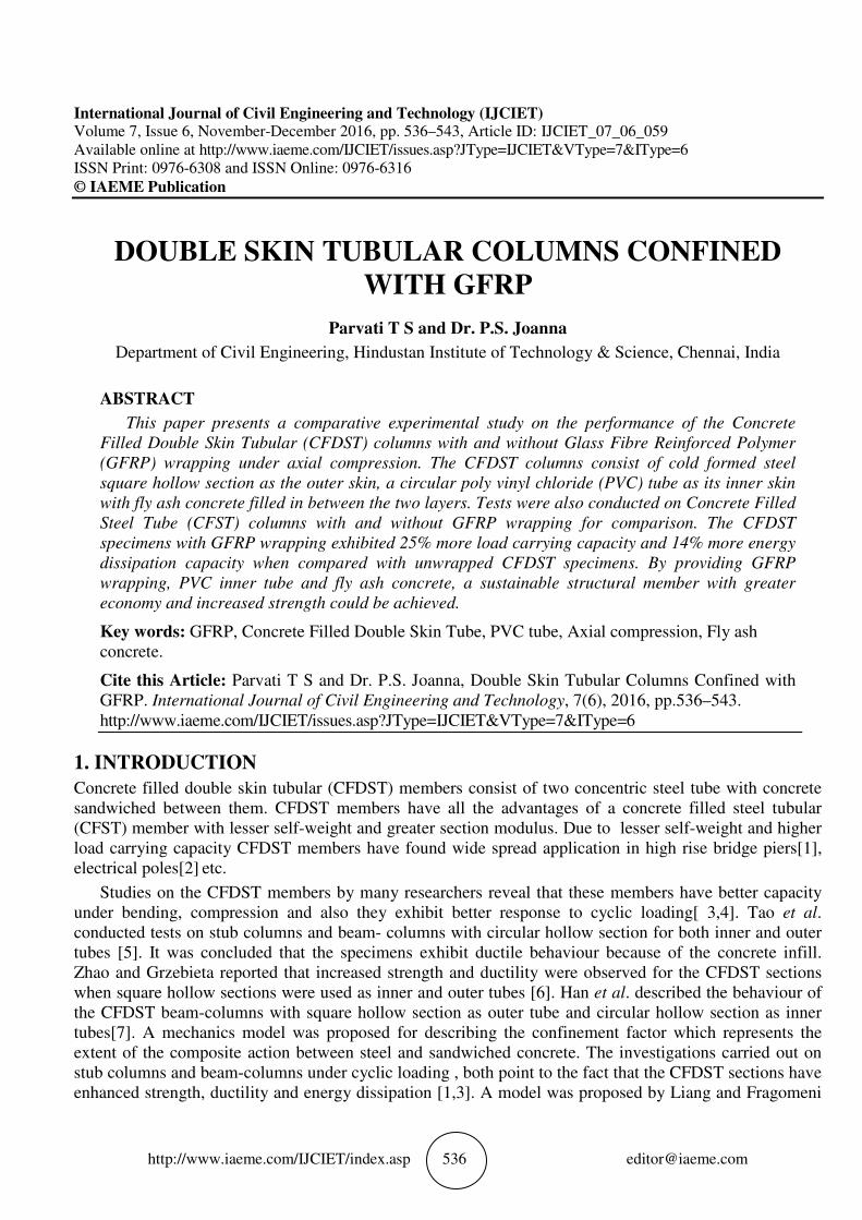
International Journal of Civil Engineering and Technology (IJCIET) Volume 7, Issue 6, November-December 2016, pp. 536–543, Article ID: IJCIET_07_06_059
Available online at http://www.iaeme.com/IJCIET/issues.asp?JType=IJCIET&VType=7&IType=6
ISSN Print: 0976-6308 and ISSN Online: 0976-6316
© IAEME Publication
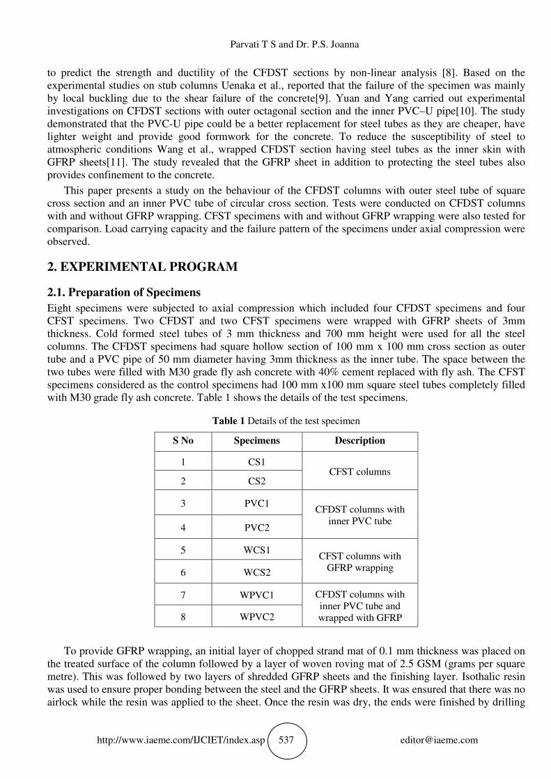
DOUBLE SKIN TUBULAR COLUMNS CONFINED
WITH GFRP
Parvati T S and Dr. P.S. Joanna
Department of Civil Engineering, Hindustan Institute of Technology & Science, Chennai, India
ABSTRACT
This paper presents a comparative experimental study on the performance of the Concrete
Filled Double Skin Tubular (CFDST) columns with and without Glass Fibre Reinforced Polymer
(GFRP) wrapping under axial compression. The CFDST columns consist of cold formed steel
square hollow section as the outer skin, a circular poly vinyl chloride (PVC) tube as its inner skin
with fly ash concrete filled in between the two layers. Tests were also conducted on Concrete Filled
Steel Tube (CFST) columns with and without GFRP wrapping for comparison. The CFDST
specimens with GFRP wrapping exhibited 25% more load carrying capacity and 14% more energy
dissipation capacity when compared with unwrapped CFDST specimens. By providing GFRP
wrapping, PVC inner tube and fly ash concrete, a sustainable structural member with greater
economy and increased strength could be achieved.
Key words: GFRP, Concrete Filled Double Skin Tube, PVC tube, Axial compression, Fly ash
concrete.
Cite this Article: Parvati T S and Dr. P.S. Joanna, Double Skin Tubular Columns Confined with
GFRP. International Journal of Civil Engineering and Technology, 7(6), 2016, pp.536–543.
http://www.iaeme.com/IJCIET/issues.asp?JType=IJCIET&VType=7&IType=6
1. INTRODUCTION
Concrete filled double skin tubular (CFDST) members consist of two concentric steel tube with concrete
sandwiched between them. CFDST members have all the advantages of a concrete filled steel tubular
(CFST) member with lesser self-weight and greater section modulus. Due to lesser self-weight and higher
load carrying capacity CFDST members have found wide spread application in high rise bridge piers[1],
electrical poles[2] etc.
Studies on the CFDST members by many researchers reveal that these members have better capacity
under bending, compression and also they exhibit better response to cyclic loading[ 3,4]. Tao et al.
conducted tests on stub columns and beam- columns with circular hollow section for both inner and outer
tubes [5]. It was concluded that the specimens exhibit ductile behaviour because of the concrete infill.
Zhao and Grzebieta reported that increased strength and ductility were observed for the CFDST sections
when square hollow sections were used as inner and outer tubes [6]. Han et al. described the behaviour of
the CFDST beam-columns with square hollow section as outer tube and circular hollow section as inner
tubes[7]. A mechanics model was proposed for describing the confinement factor which represents the
extent of the composite action between steel and sandwiched concrete. The investigations carried out on
stub columns and beam-columns under cyclic loading , both point to the fact that the CFDST sections have
enhanced strength, ductility and energy dissipation [1,3]. A model was proposed by Liang and Fragomeni
Parvati T S and Dr. P.S. Joanna
http://www.iaeme.com/IJCIET/index.asp 537 [email protected]
to predict the strength and ductility of the CFDST sections by non-linear analysis [8]. Based on the
experimental studies on stub columns Uenaka et al., reported that the failure of the specimen was mainly
by local buckling due to the shear failure of the concrete[9]. Yuan and Yang carried out experimental
investigations on CFDST sections with outer octagonal section and the inner PVC–U pipe[10]. The study
demonstrated that the PVC-U pipe could be a better replacement for steel tubes as they are cheaper, have
lighter weight and provide good formwork for the concrete. To reduce the susceptibility of steel to
atmospheric conditions Wang et al., wrapped CFDST section having steel tubes as the inner skin with
GFRP sheets[11]. The study revealed that the GFRP sheet in addition to protecting the steel tubes also
provides confinement to the concrete.
This paper presents a study on the behaviour of the CFDST columns with outer steel tube of square
cross section and an inner PVC tube of circular cross section. Tests were conducted on CFDST columns
with and without GFRP wrapping. CFST specimens with and without GFRP wrapping were also tested for
comparison. Load carrying capacity and the failure pattern of the specimens under axial compression were
observed.
2. EXPERIMENTAL PROGRAM
2.1. Preparation of Specimens
Eight specimens were subjected to axial compression which included four CFDST specimens and four
CFST specimens. Two CFDST and two CFST specimens were wrapped with GFRP sheets of 3mm
thickness. Cold formed steel tubes of 3 mm thickness and 700 mm height were used for all the steel
columns. The CFDST specimens had square hollow section of 100 mm x 100 mm cross section as outer
tube and a PVC pipe of 50 mm diameter having 3mm thickness as the inner tube. The space between the
two tubes were filled with M30 grade fly ash concrete with 40% cement replaced with fly ash. The CFST
specimens considered as the control specimens had 100 mm x100 mm square steel tubes completely filled
with M30 grade fly ash concrete. Table 1 shows the details of the test specimens.
Table 1 Details of the test specimen
S No Specimens Description
1 CS1 CFST columns
2 CS2
3 PVC1 CFDST columns with
inner PVC tube 4 PVC2
5 WCS1 CFST columns with
GFRP wrapping 6 WCS2
7 WPVC1 CFDST columns with
inner PVC tube and
wrapped with GFRP 8 WPVC2
To provide GFRP wrapping, an initial layer of chopped strand mat of 0.1 mm thickness was placed on
the treated surface of the column followed by a layer of woven roving mat of 2.5 GSM (grams per square
metre). This was followed by two layers of shredded GFRP sheets and the finishing layer. Isothalic resin
was used to ensure proper bonding between the steel and the GFRP sheets. It was ensured that there was no
airlock while the resin was applied to the sheet. Once the resin was dry, the ends were finished by drilling

Double Skin Tubular Columns Confined with GFRP
http://www.iaeme.com/IJCIET/index.asp 538 [email protected]
of the excess length. The PVC tubes were placed at the centre of the square hollow sections and held in
position by small steel pieces attached to the inner side of the outer tube. Concrete was then filled in
between the two layers by providing proper compaction.
2.2. Material Properties
The material properties of the GFRP sheets were studied by carrying out coupon tests on three flat
specimens. The GFRP specimens exhibited a yield stress of 66.69 N/mm2. The material properties of the
cold formed steel tubes were also gathered by conducting coupon tests on the samples cut from the square
hollow steel tubes. The steel tubes exhibited yield strength of 479 N/mm2. The concrete filled in the
specimens were M30 grade fly ash concrete with 40% cement replacement by fly ash. The concrete used in
the specimens were mixed with a ratio of cement, sand, aggregate as 1: 1.86:2.9 and a water- cement ratio
of 0.45. Glenium super plasticizer was added to increase the workability. Self-curing compound was added
to aid curing of the concrete. Three cubes were cast and cured under similar conditions. The average cube
compressive strength at 56 days was 30.8 N/mm2. Figure 1 shows the fabricated specimen. Figure 2 and
Figure 3 shows the concrete filled CFDST and CFST column specimen respectively.
a) CFST b) CFDST
Figure 1 Fabricated Specimens
Figure 2 Concrete filled CFDST specimens Figure 3 Concrete filled CFST specimen with inner
PVC tube

http://www.iaeme.com/IJCIET/index.asp
2.3. Test Set-up
Tests were performed in a 1000 kN capacity Universal Testing
data logger. The short column specimens were placed on the testing machine and the axial load was
applied on the specimen directly as the loading ram was a solid steel plate. The load was applied at the rate
of 0.8kN/sec and the test was stopped when the load was found to reduce with increase in axial
displacement. Figure 4 shows the test set up.
3. RESULT AND DISCUSSIO
3.1. Failure Modes
Figure 5 shows the load-deformation curves of the
exhibited an elastic response indicated by the linear portion of the load deflection graph. On further
loading, there was a gradual increase of load till the peak value. Beyond peak load, different spec
exhibited different load-deformation patterns. Control specimens CS1 and CS2 exhibited a round bend in
the load deflection graph indicating non
observed in the specimens CS1 and CS2 at th
an inclined fold at one-third height indicating shear failure in the specimen.
The CFDST specimens with inner PVC tubes also exhibited the non
round bend in the graph. ‘Elephant foot’ formation was observed at the top of the
and PVC2.
GFRP wrapped CFST specimens WCS1 and WCS2 also exhibited a gradually increasing load but with
a sharp yield point followed by a plastic zone. Bulge formation was o
de-bonding of the GFRP laminate from the steel tube in WCS1. WCS2 exhibited bulge formation at mid
height of the column with the rupture of GFRP laminate.
Figure 5 Load-Deformation Curve
Parvati T S and Dr. P.S. Joanna
http://www.iaeme.com/IJCIET/index.asp 539
Tests were performed in a 1000 kN capacity Universal Testing Machine and the data were collected by a
data logger. The short column specimens were placed on the testing machine and the axial load was
applied on the specimen directly as the loading ram was a solid steel plate. The load was applied at the rate
N/sec and the test was stopped when the load was found to reduce with increase in axial
displacement. Figure 4 shows the test set up.
Figure 4 Test Set up
RESULT AND DISCUSSION
deformation curves of the eight specimens.On application of load, the specimens
exhibited an elastic response indicated by the linear portion of the load deflection graph. On further
loading, there was a gradual increase of load till the peak value. Beyond peak load, different spec
deformation patterns. Control specimens CS1 and CS2 exhibited a round bend in
the load deflection graph indicating non-linear response of both steel and concrete. Local buckling was
and CS2 at the lower end of the column. The specimen CS2 also developed
third height indicating shear failure in the specimen.
The CFDST specimens with inner PVC tubes also exhibited the non-linear response validated by the
lephant foot’ formation was observed at the top of the
GFRP wrapped CFST specimens WCS1 and WCS2 also exhibited a gradually increasing load but with
a sharp yield point followed by a plastic zone. Bulge formation was observed at the top of the column with
bonding of the GFRP laminate from the steel tube in WCS1. WCS2 exhibited bulge formation at mid
th the rupture of GFRP laminate.
Deformation Curve Figure 6 Inward folding of inner PVC tube
Machine and the data were collected by a
data logger. The short column specimens were placed on the testing machine and the axial load was
applied on the specimen directly as the loading ram was a solid steel plate. The load was applied at the rate
N/sec and the test was stopped when the load was found to reduce with increase in axial
On application of load, the specimens
exhibited an elastic response indicated by the linear portion of the load deflection graph. On further
loading, there was a gradual increase of load till the peak value. Beyond peak load, different specimens
deformation patterns. Control specimens CS1 and CS2 exhibited a round bend in
linear response of both steel and concrete. Local buckling was
e lower end of the column. The specimen CS2 also developed
linear response validated by the
lephant foot’ formation was observed at the top of the column specimens PVC1
GFRP wrapped CFST specimens WCS1 and WCS2 also exhibited a gradually increasing load but with
bserved at the top of the column with
bonding of the GFRP laminate from the steel tube in WCS1. WCS2 exhibited bulge formation at mid
Inward folding of inner PVC tube

Double Skin Tubular Columns Confined with GFRP
http://www.iaeme.com/IJCIET/index.asp
Wrapped CFDST specimens WPVC1 and WPVC2 exhibited a slightly varied load
The load-deflection curve of the WPVC2 specimen was similar to WCS1 and WCS2 w
point and a plastic zone. Whereas, WPVC1 exhibited a rounded peak followed by plastic zone and when
loaded further the specimen exhibited an increased peak load. This increase in load capacity may be
attributed to the strain hardening eff
The wrapped CFDST specimens failed with multiple folds and subsequent rupture of the GFRP
lamination. The PVC inner tubes
inward folding at the end of testing
Figure 7 shows the load deformation curve of WPVC1 indicating the number of peaks developed in the
specimen. Figure 5 shows the load
deflection of 15mm.
Figure 7
3.2. Load Carrying Capacity
Test results of the column sections are given in Table 2.
average peak load of 895.02kN and the CFDST specimens (PVC1 and PVC2) was able
average peak load of 713.2kN.The GFRP wrapped CFST specimens failed at an average load of 910.9
and the wrapped CFDST specimens exhibited an average maximum load of 894.
S No Specimens
1
2
3
4
5
6
7
8
Double Skin Tubular Columns Confined with GFRP
http://www.iaeme.com/IJCIET/index.asp 540
Wrapped CFDST specimens WPVC1 and WPVC2 exhibited a slightly varied load
deflection curve of the WPVC2 specimen was similar to WCS1 and WCS2 w
point and a plastic zone. Whereas, WPVC1 exhibited a rounded peak followed by plastic zone and when
loaded further the specimen exhibited an increased peak load. This increase in load capacity may be
attributed to the strain hardening effect.
The wrapped CFDST specimens failed with multiple folds and subsequent rupture of the GFRP
PVC inner tubes of all CFDST specimens (both wrapped and unwrapped) exhibited
at the end of testing (Figure 6) indicating the loss of confinement
Figure 7 shows the load deformation curve of WPVC1 indicating the number of peaks developed in the
specimen. Figure 5 shows the load-deflection curves with single peak as the curves are plotted to a
Figure 7 Load-deformation curve for WPVC1
Test results of the column sections are given in Table 2. CFST specimens (CS1 and CS2
kN and the CFDST specimens (PVC1 and PVC2) was able
average peak load of 713.2kN.The GFRP wrapped CFST specimens failed at an average load of 910.9
and the wrapped CFDST specimens exhibited an average maximum load of 894.
Table 2 Test results of column sections
Specimens Peak Load (kN) Average Peak
Load (kN)
CS1 891.97 895.02
CS2 898.08
PVC1 671.22 713.2
PVC2 756.02
WCS1 910.89 910.91
WCS2 910.94
WPVC1 877.9 894.33
WPVC2 910.75
Double Skin Tubular Columns Confined with GFRP
Wrapped CFDST specimens WPVC1 and WPVC2 exhibited a slightly varied load-deflection pattern.
deflection curve of the WPVC2 specimen was similar to WCS1 and WCS2 with a sharp yield
point and a plastic zone. Whereas, WPVC1 exhibited a rounded peak followed by plastic zone and when
loaded further the specimen exhibited an increased peak load. This increase in load capacity may be
The wrapped CFDST specimens failed with multiple folds and subsequent rupture of the GFRP
(both wrapped and unwrapped) exhibited
s of confinement (Elchalakani et al., 2002).
Figure 7 shows the load deformation curve of WPVC1 indicating the number of peaks developed in the
deflection curves with single peak as the curves are plotted to a
CFST specimens (CS1 and CS2) exhibited
kN and the CFDST specimens (PVC1 and PVC2) was able to sustain an
average peak load of 713.2kN.The GFRP wrapped CFST specimens failed at an average load of 910.91 kN
and the wrapped CFDST specimens exhibited an average maximum load of 894.33 kN .
Average Peak
Load (kN)
895.02
713.2
910.91
894.33

Parvati T S and Dr. P.S. Joanna
http://www.iaeme.com/IJCIET/index.asp 541 [email protected]
0
100
200
300
400
500
600
700
800
900
1000
CS PVC WCS WPVC
Pe
ak
Lo
ad
(kN
)
Specimen
The CFST columns (both wrapped and without wrapping) exhibit higher load carrying capacity than
the CFDST specimens. But when wrapped, the CFDST specimens failed at a load equivalent to the CFST
specimens. Also, the wrapped CFDST specimens exhibited 25% more load carrying capacity than the
unwrapped specimens. This increase in the load capacity compared to unwrapped specimens may be
attributed to the confinement effect offered by GFRP laminates to the CFDST section. Figure 7 shows the
strength variation in the specimens. The failure pattern of the wrapped CFDST specimen is shown in
Figure 8. Figure 9 and Figure 10 shows the failure pattern in all the CFST and CFDST specimens
respectively.
Figure 7 Strength variation of the specimens Figure 8 Failure pattern of WPVC specimen
Figure 9 Failure pattern of CFDST specimens Figure10 Failure pattern of the CFST specimens
3.3. Energy Absorption or Energy Dissipation
The energy absorption is measured by the area under the load-deformation diagram. The energy absorbed
up to 20mm deformation was calculated. The energy absorption capacity of the various column specimens
are given in Table 3.
WPVC specimens have nearly 14% more absorption capacity than the PVC specimens. Thus by
providing GFRP wrapping the energy absorption capacity is greatly increased indicating adequate
confinement provided by the wrapping.
Bulge
fo
r
m
ati
on

Double Skin Tubular Columns Confined with GFRP
http://www.iaeme.com/IJCIET/index.asp 542 [email protected]
Table 3 Energy Absorption capacity
SNo Specimens Energy
Absorption (kN-
mm)
Average Energy
Absorption (kN-
mm)
1 CS1 9682.76 9611.24
2 CS2 9539.72
3 PVC1 6847.27 7542.21
4 PVC2 8237.16
5 WCS1 9578.94 9887.16
6 WCS2 10195.39
7 WPVC1 7839.44
8580.29 8 WPVC2 9321.15
4. CONCLUSION
Axial compression tests were conducted on four CFDST and four CFST specimens and the following
conclusions were drawn
• The wrapped CFDST specimens with inner PVC pipe exhibited 25% more load carrying capacity than the
unwrapped CFDST specimen.
• The energy absorption capacity of the wrapped CFDST specimen with inner PVC pipe is 14% more than the
CFDST specimen without wrapping.
• The wrapped CFDST columns exhibit nearly the same load carrying capacity as the wrapped CFST
specimens.
• The GFRP wrapping protects the steel tube from atmospheric effects and adoption of fly ash concrete
ensures the column to be a sustainable member with lesser self weight and greater economy.
Due to the high load carrying capacity, lesser weight and better energy absorption capacity, GFRP
wrapped CFDST columns could be used in regions of high seismic activity.
REFERENCE
[1] Elchalakani, M., Zhao, X.-L. & Grzebieta, R. Tests on concrete filled double-skin (CHS outer and SHS
inner) composite short columns under axial compression. Thin-Walled Structures 40, 2002,pp.415–441.
[2] Li, W., Han, L.-H. & Chan, T.-M. Tensile behaviour of concrete-filled double-skin steel tubular
members. Journal of Constructional Steel Research 99, 2014,pp.35–46.
[3] Han, L.-H., Huang, H., Tao, Z. & Zhao, X.-L. Concrete-filled double skin steel tubular (CFDST) beam–
columns subjected to cyclic bending. Engineering Structures 28, 2006,pp.1698–1714 .
[4] Tao, Z. & Han, L.-H. Behaviour of concrete-filled double skin rectangular steel tubular beam–columns.
Journal of Constructional Steel Research 62, 2006, pp. 631–646 .
[5] Tao, Z., Han, L.-H. & Zhao, X.-L. Behaviour of concrete-filled double skin (CHS inner and CHS outer)
steel tubular stub columns and beam-columns. Journal of Constructional Steel Research 60, 2004,
pp.1129–1158.
[6] Zhao, X.-L. & Grzebieta, R. Strength and ductility of concrete filled double skin (SHS inner and SHS
outer) tubes. Thin-Walled Structures 40, 2002 , pp.199–213 .
[7] Han, L.-H., Tao, Z., Huang, H. & Zhao, X.-L. Concrete-filled double skin (SHS outer and CHS inner)
steel tubular beam-columns. Thin-Walled Structures 42, 2004 , pp.1329–1355 .

Parvati T S and Dr. P.S. Joanna
http://www.iaeme.com/IJCIET/index.asp 543 [email protected]
[8] Liang, Q. Q. & Fragomeni, S. Nonlinear analysis of circular concrete-filled steel tubular short columns
under axial loading. Journal of Constructional Steel Research 65, 2009, pp.2186–2196 .
[9] Uenaka, K., Kitoh, H. & Sonoda, K. Concrete filled double skin circular stub columns under
compression. Thin-Walled Structures 48, 2010, pp.19–24 .
[10] Yuan, W. & Yang, J. Experimental and numerical studies of short concrete-filled double skin composite
tube columns under axially compressive loads. Journal of Constructional Steel Research 80, 2013,
pp.23–31.
[11] Wang, J., Liu, W., Zhou, D., Zhu, L. & Fang, H. Mechanical behaviour of concrete filled double skin
steel tubular stub columns confined by FRP under axial compression. Steel and Composite Structures
17, 2014, pp.431–452.
[12] Ali S. Shanour, Ahmed A. Mahmoud, Maher A. Adam And Mohamed Said, Experimental Investigation
of Concrete Beams Reinforced With GFRP Bars. International Journal of Civil Engineering and
Technology 9IJCIET), 5(11), 2014, pp.154–164.
[13] Pradeepa. S, Gokul Raj. D and Divya M.R, A Review on Cost Assessment of Conventional Steel
Structure and Square Tubular Sections Using Force Co-Efficient Method. International Journal of Civil
Engineering and Technology (IJCIET), 7(4), 2016, pp.242–245.