Embed Size (px)
Citation preview

Double Block andBleed FlangedProductsCatalog 4190-FPNovember 2005

Parker Hannifin Corporation
Flanged Products
2
ContentsPage 2 Introduction.
Page 3 Application illustrations.
Page 4 Ball valve specification.
Page 5Outside screw and yoke (O.S.&Y.) valve specification.
Page 6 Globe style needle valve specification.
Page 7 Bolted bonnet.
Page 8/11 Monoflange (MF) manifolds.
Page 12/15 Pro-Bloc® (PB) manifolds.
Page 16 Other flange detail options.
Page 17 Pro-Bloc® (SPB) for sampling applications.
Page 18 Pro-Bloc® (JPB) for injection applications.
Stainless steel Std
S
Monel
M
Duplex
D1
Super Duplex
D2
Hasteloy
HC
Steel
C6MO
T25
Material
for sele
material in
part number
IntroductionParker Hannifin’s response to the demand for reduction in leakage paths has been the combination of primary andsecondary valves into one compact unit. The combining of piping and instrument valves into a single unit hasbenefitted various markets.Parker Hannifin can offer the unique combination of double block and bleed valve systems together with integralfittings, both being designed and produced by one company. Selection of this combination results in theelimination of taper thread connections and the need for thread sealant. For more information on leak pathreductions and how to combine connections and valves into one unit, please contact us.
Parker Hannifin Corporation
Flanged Products
3
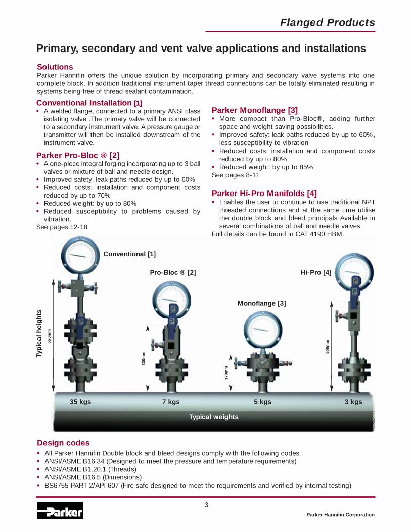
Primary, secondary and vent valve applications and installations
Design codes• All Parker Hannifin Double block and bleed designs comply with the following codes.• ANSI/ASME B16.34 (Designed to meet the pressure and temperature requirements)• ANSI/ASME B1.20.1 (Threads)• ANSI/ASME B16.5 (Dimensions)• BS6755 PART 2/API 607 (Fire safe designed to meet the requirements and verified by internal testing)
SolutionsParker Hannifin offers the unique solution by incorporating primary and secondary valve systems into onecomplete block. In addition traditional instrument taper thread connections can be totally eliminated resulting insystems being free of thread sealant contamination.
650m
m
330m
m
170m
m
500m
m
Typ
ical
hei
ght
s
Typical weights
35 kgs 7 kgs 5 kgs 3 kgs
Conventional Installation [[11]]• A welded flange, connected to a primary ANSI class
isolating valve .The primary valve will be connectedto a secondary instrument valve. A pressure gauge ortransmitter will then be installed downstream of theinstrument valve.
Parker Pro-Bloc ® [2]• A one-piece integral forging incorporating up to 3 ball
valves or mixture of ball and needle design.• Improved safety: leak paths reduced by up to 60%• Reduced costs: installation and component costs
reduced by up to 70%• Reduced weight: by up to 80%• Reduced susceptibility to problems caused by
vibration.See pages 12-18
Parker Monoflange [3]• More compact than Pro-Bloc®, adding further
space and weight saving possibilities.• Improved safety: leak paths reduced by up to 60%,
less susceptibility to vibration• Reduced costs: installation and component costs
reduced by up to 80%• Reduced weight: by up to 85%See pages 8-11
Parker Hi-Pro Manifolds [4]• Enables the user to continue to use traditional NPT
threaded connections and at the same time utilisethe double block and bleed principals Available inseveral combinations of ball and needle valves.
Full details can be found in CAT 4190 HBM.
Pro-Bloc ® [2]
Conventional [1]
Hi-Pro [4]
Monoflange [3]

Performance Data Pressure vs temperature
Flanged Products
Parker Hannifin Corporation
4
Spanner actuation
IItteemm DDeessccrriippttiioonn
1 End Connector
2 E-seal™
3 Sealing washer
4 Seats
5 Body
6 Ball
7 Anti blowout stem
8 Thrust Seal
9 Gland packing
10 Upper gland packing
11 Thrust bush
12 Stop pin
13 Thrust bush
14 Lock nut
15 Locking dome nut
16 Handle
17 Handle grip
Part description
Specifications• 316 Stainless steel construction.
• Maximum cold working pressure rating 6,000 psig (414 barg) with P.T.F.E. seats.*
• Temperature rating PTFE seats-54˚C to +204˚C (-65˚F to +400˚F).*
• Maximum cold working pressure rating 10,000 psig (689 barg) with PEEK seats.*
• Temperature rating PEEK seats-54˚C to +232˚C (-65˚F to +450˚F).*
*always refer to P/T graph
Features• Two piece body design - minimal leakage
paths.• 4:1 Pressure boundary designed safety factor.• Designed to comply with requirements of
ANSI/ASME B16.34 where applicable.• Bi-directional.• PEEK and PTFE standard ball seat materials.• PTFE and Graphoil gland packings.• Bubble tight shutoff.• Floating ball principal with dynamic response
seats featuring inherent self relief.• Anti blowout stem.• Integral compression ends available eliminating
taper threads and thread sealants.• Low torque operation.• Quarter turn positive stop handle with
ergonomically designed protective sleeve.• Full hydrostatic and low pressure air tested.• Connector thread environmentally sealed.• Anti static.• Firesafe designed to meet BS6755 Part 2/
API 607, (optional).
Optional bolted endconnector
Handle locking
Ball valve specification
* See catalogue 4190-HBV Hi-Pro Ball Valve for High PerformanceProcess Isolation.
Parker Hannifin Corporation
Flanged Products
5
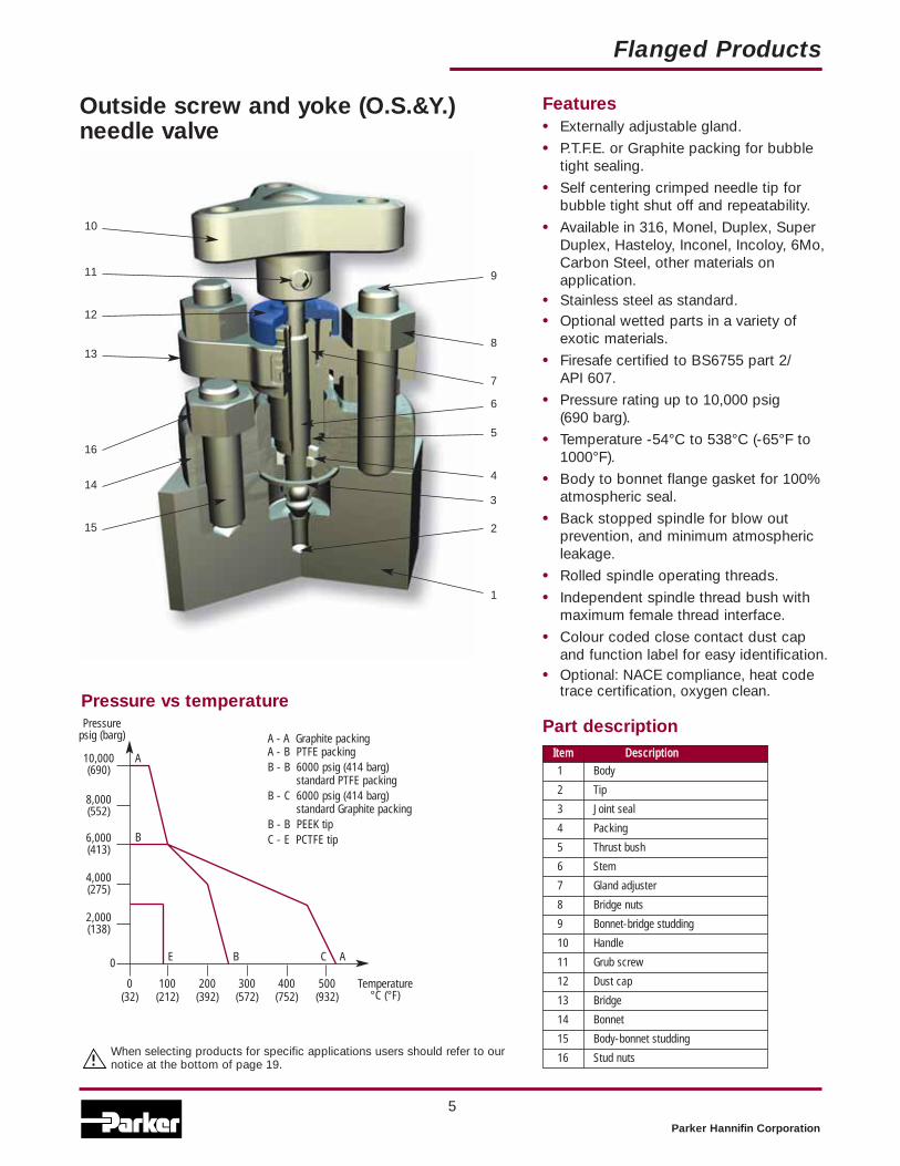
Outside screw and yoke (O.S.&Y.)needle valve
Features• Externally adjustable gland.
• P.T.F.E. or Graphite packing for bubbletight sealing.
• Self centering crimped needle tip forbubble tight shut off and repeatability.
• Available in 316, Monel, Duplex, SuperDuplex, Hasteloy, Inconel, Incoloy, 6Mo,Carbon Steel, other materials onapplication.
• Stainless steel as standard.• Optional wetted parts in a variety of
exotic materials.
• Firesafe certified to BS6755 part 2/ API 607.
• Pressure rating up to 10,000 psig (690 barg).
• Temperature -54°C to 538°C (-65°F to1000°F).
• Body to bonnet flange gasket for 100%atmospheric seal.
• Back stopped spindle for blow outprevention, and minimum atmosphericleakage.
• Rolled spindle operating threads.
• Independent spindle thread bush withmaximum female thread interface.
• Colour coded close contact dust capand function label for easy identification.
• Optional: NACE compliance, heat codetrace certification, oxygen clean.
IItteemm DDeessccrriippttiioonn
1 Body
2 Tip
3 Joint seal
4 Packing
5 Thrust bush
6 Stem
7 Gland adjuster
8 Bridge nuts
9 Bonnet-bridge studding
10 Handle
11 Grub screw
12 Dust cap
13 Bridge
14 Bonnet
15 Body-bonnet studding
16 Stud nuts
Part descriptionPressure vs temperature
0 100 200 300 400 500(32) (212) (392) (572) (752) (932)
10,000(690)
8,000(552)
6,000(413)
4,000(275)
2,000(138)
0
Pressurepsig (barg) A - A Graphite packing
A - B PTFE packingB - B 6000 psig (414 barg)
standard PTFE packingB - C 6000 psig (414 barg)
standard Graphite packingB - B PEEK tipC - E PCTFE tip
Temperature°C (°F)
A
B
E B C A
1
2
3
4
5
6
7
8
9
10
11
12
13
16
14
15
When selecting products for specific applications users should refer to ournotice at the bottom of page 19.

Parker Hannifin Corporation
6
Flanged Products
IItteemm DDeessccrriippttiioonn
1 Positive handle retention
2 “T” bar
3 Dust Cap
4 Gland packing adjuster
5 Gland adjuster lock nut
6 Valve Bonnet
7 Anti blowout spindle
8 Thrust Bush
9 Gland packing (adjustable)
10 Bonnet/body washer
11 Spindle tip
Part description
Pressure vs temperature
0 100 200 300 400 500(32) (212) (392) (572) (752) (932)
10,000(690)
8,000(552)
6,000(413)
4,000(275)
2,000(138)
0
Pressurepsig (barg) A - A Graphoil packing
A - B PTFE packingB - B 6000 psig (414 barg)
standard PTFE packingB - C 6000 psig (414 barg)
standard Graphoil packingA - D PEEK tipC - E PCTFE tip
Temp°C (°F)
A
B
C
E D B C A
“H” Series globe style needle valve
For safe, reliable and repeatableperformance
1
3
5
7
9
11
2
4
6
8
10
Features• Rolled spindle operating threads for low
torque operation.
• Gland packing in PTFE or Graphite forbubble tight sealing.
• Colour coded close contact dust cap andfunction label for easy identification.
• Available in 316L, Monel, Duplex, SuperDuplex, Hasteloy, Inconel, Incoloy, 6Mo,Titanium, other materials on application.
• T-bar operating handle for low torquefunction.
• Self centering crimped needle tip for bubbletight seat sealing.
• Close contact dust cap for operating threadprotection.
• Back seated spindle for blow out preventionand minimum atmospheric leakage.
• Adjustable gland with easy access.
• Gland lock nut for vibration protection.
• Pressure rating up to 10,000 psig (690 barg).
• Temperature rating -54°C to -538°C (-65°F to 1000°F)
• Optional bolted bonnet design available,firesafe certified.
• Optional: NACE compliance, heat code tracecertification, oxygen clean.
When selecting products for specific applications users should refer toour notice at the bottom of page 19.

Flanged Products
Parker Hannifin Corporation
7
Bolted bonnet
Anti tamper spindle
For key only - part no. ATHKEY/1
Retro-fit kit part numberKITAT without keyKITATK with key
Retro-fit kit part number KITTHL
IItteemm DDeessccrriippttiioonn
1 Body
2 Tip
3 Joint seal
4 Packing
5 Thrust bush
6 Stem
7 Nut
8 Gland adjuster
9 Handle
10 Grub screw
11 Dust cap
12 Bonnet
13 Body-bonnet studding
14 Stud nuts
Part description
1
2
3
4
5
6
7
9
10
11
8
13
14
12
T bar handle locking

Parker Hannifin Corporation
Flanged Products
8
Monoflange (MF) manifolds
PurposeThis manifold range is designed to replace conventional multiple-valve installations currently in use for interfacewith pressure measuring systems. By combining customer specified valves into a single manifold, the number ofleak paths is considerably reduced and the mass of the system is lowered reducing the stresses from loading andvibration. The result of which substantially improves installation and operational safety factors. Reduction inleakage path connections together with a one-piece solution also provides positive installation cost savings.
Instrument outlet connectionsOne of the unique features Parker can offer users which can further enhance safety factors is the incorporationof single or twin ferrule compression fittings as an integral part of the outlet connection.Installation of the instrument which require remote positioning will be interconnected using conventional tube andfittings, whilst NPT taper threads are accepted as a standard their use involves some form of thread sealant whichadds to the complication of instrument performance through contamination within the system.Avoiding these taper thread connections wherever possible reduces this contaminant risk and Parker, being aleading manufacturer of compression type of fittings (which requires no sealant mediums), can incorporate themin the outlet connection, totally eliminating the contamination risk.
Key advantages of Parker Monoflanges• Strong construction produced from one piece grain flow
controlled forged body.
• Various flow and valve configurations available allowing trueflexibility to meet all customer requirements.
• Variety of flange sizes and outlet connections.
• Standard materials of Carbon Steel A105,Low Temperature Carbon Steel A350 LF2,Stainless Steel A182-F316 andDuplex Stainless Steel A182-F51.
• Optional materials include Super Duplex, Monel, Hastelloy, 6Mo,Incoloy 625.
• Incorporation of standard “H” series needle valve technologyand state of the art O.S.&Y. design.
• 4mm Needle valve orifice.
• Ergonomically designed operating handles with low torquefunction.
• Full range of customer retro fit handle options.
• User friendly part number and specification construction system.
• Customised designs welcome.
Process
Process
Instrument outlets
Vertical Horizontal
Blanked outlets

Parker Hannifin Corporation
Flanged Products
9
Monoflange features• 1/2” to 2” N.B. Flanges (15 to 50 DN).
• ANSI B16.5 150 to 2500 flange class and API10,000.
• 1/2-14 NPT (female) standard outlet.
• 1/4-18 NPT (female) standard vent.
• Variety of optional end connection sizes andthread forms including tube connections1/2”/12mm diameter.
• Standard materials of construction: Stainlesssteel ASTM A182 F316/F316L, Carbon steelASTM A350 LF2/A105, Duplex ASTM A182 F51.
• Optional materials include Super Duplex, Monel,Hastelloy, 6Mo, Incoloy.
• Combined needle and O.S.&Y. valves available.
• Instrument connections A-LOK® invertedavailable.
• Raised face and ring type joint flange facestyles.
• One-piece forged construction flange asstandard.
• H needle design with retro fit handle options.
• Optional fire safe designed (and tested) to meetBS6755 part 2/API 607.
• Pressure boundary designs calculated to ASMEVIII Div. 1 and verified by testing.
• 4:1 Factor of Safety.
• Heat code traceable material to EN10204.3.1.
• Bubble tight shut off valve seats 17-4 PH tipsstandard.
• Optional PEEK tips available.
• Colour coded functional valves.
• Optional locking and anti tamper devices for allvalve types available.
• NACE MR 0175/ISO 15156 compliant materialavailable on request.
• Permanent marked body with full order andspecification details.
MFY100MFY110
MFY140
MFH100MFH110
Standard specification:Outlet - 1/2” FNPT Vent - plugged 1/4” FNPT Seat - metal/metal St. St. Packing - PTFE

Parker Hannifin Corporation
Flanged Products
10
Monoflange (MF) manifold selection and part number construction - made easySelect the style of Monoflange from the choice of arrangements below noting the complete MF reference.If the style or arrangement is not shown below please provide full description and specification.
MFH100
MFH110
MFH120
MFH130
MFH140
MFH150
MFY100
MFY110
MFY120
MFY130
MFY140
MFY150
Block bleed block1st Isolate: Needle2nd Isolate: NeedleVent: Needle
Block bleed block1st Isolate: O.S.&Y.2nd Isolate: NeedleVent: Needle
Block block bleed1st Isolate: O.S.&Y.2nd Isolate: NeedleVent: Needle
Block & bleed1st Isolate: O.S.&Y.Vent: Needle
Block & bleed1st Isolate: O.S.&Y.Vent: Needle
Double block1st Isolate: O.S.&Y.2nd Isolate: Needle.
Single block1st Isolate: O.S.&Y.
Block block bleed1st Isolate: Needle2nd Isolate: NeedleVent: Needle
Block & bleed1st Isolate: NeedleVent: Needle
Block & bleed1st Isolate: NeedleVent: Needle
Double block1st Isolate: Needle2nd Isolate: Needle
Single block1st Isolate: Needle
**
▲ For dual outlets specify MFH105, MFH115, MFY105, MFY115Other flow path options: MF*160 Bleed only, MF*200 Flange to flange design,MFY102 O.S.&Y. Primary and secondary isolate, MFY117 O.S.&Y. All round and dual outlet. Please note vent valve is notanti-tamper as std.
▲
▲
▲
▲

5. Plugged vent (1/4”5. FNPT is standard5. NO part designator5. needed)
SizeV6 = 3/8” FNPTV8 = 1/2” FNPT
Parker Hannifin Corporation
Flanged Products
11
Example MFY100 B 32T2500 8F V6F A3 F
3. Flange detailsFlange Flange Face Style Flange Class
Size80 = 1/2” F = Raised Face Spiral 1500 = 15012 = 3/4” T = Ring Type Joint 3000 = 30016 = 1” 6000 = 60024 = 1 1/2” 9000 = 90032 = 2” 1500 = 1500API specify separately 2500 = 2500DIN see page 16 1360 = 150/300/*1/2” flange size only 1360 = 600
4. Outlet style (1/2” FNPT is standard4. NO part designator needed)
Size Connection Style40M = 1/4” F = Female NPT Thread60M = 3/8” M = Male NPT Thread80M = 1/2” A = A-LOK® (invertedM60 = 6mm A = only)M10 = 10mm G = Swivel gaugeM12 = 12mm G = adaptor 1/2”
G = NPTF (fitted)
IMPORTANT NOTES
All non wetted parts will be supplied in standard stainless steel for exotic materials. For carbon steel construction trim materials will besupplied in stainless steel.Ring type joints (T) CANNOT be supplied for 1/2” & 3/4” class 150 flanges.St. St. grades 302 and 304 are NOT used in the construction of any of these products.For customer specific options not covered here engineering will allocate a part number at quotation stage.Certification requirements and customer specifications MUST be provided at enquiry and order stage.For API flange requirements full details must be specified separately.Part number example MFY100B32T2500A3F Monoflange - Double Block and Bleed - Block (O.S.&Y.) Bleed (Needle) Block (Needle)(MFY100) - 316 St. St. construction (B) - 2” Pipe flange, Ring type joint, class 2500 (32T2500) - 1/2” female NPT outlet - 1/4” Female NPTvent - Anti-tamper vent (A3) - Firesafe design and certified (F), valves fitted with PTFE packing, metal seated 17-4PH st.st. tips.
1. Monoflange part number1. Insert from page 10
2. MaterialA Carbon Steel ASTM A105B Stainless Steel ASTM A182-F316D Monel M400E Duplex ASTM A182-F51F Super Duplex ASTM A182-F53G Hastelloy C-276H Low Temp. C. St. ASTM A350 LF2K 6MoM Inconel 625
6. Valve packing and seat materials* PTFE Packing* Needle tip 17-4PH St. St.3 Graphoil (fitted as standard
when fire safe design is specified)PN PEEK Needle tip all valves (non
fire safe only)* fitted as standard no part NOdesignator required.
7. Valve handle operating optionsA* Anti tamperL* Padlock handle lockingR* Regulating tip (“H” series
needle valve only)* Insert valve number 1 = primary,2 = secondary, 3 = vent, 4 = all.Padlocks not supplied
8. Certification & conditionF Firesafe design and certified
(primary only - O.S.&Y.needle valve)
H Heat code certificates toEN10204.3.1.B
N NACECombine designators asrequired
*}
When selecting products for specific applications usersshould refer to our notice at the bottom of page 19.

Parker Hannifin Corporation
Flanged Products
12
Pro-Bloc® (PB) Manifolds
PurposeThis manifold range is designed to replace conventional multiple-valve installations currently in use for interfacewith pressure measuring systems. By combining customer specified valves into a single manifold, the number ofleak paths is considerably reduced and the mass of the system is lowered reducing the stresses from loading andvibration. The result of which substantially improves installation and operational safety factors. Reduction inleakage path connections together with a one-piece solution also provides positive installation cost savings.
Instrument outlet connectionsOne of the unique features Parker can offer users which can further enhance safety factors is the incorporationof single or twin ferrule compression fittings as an integral part of the outlet connection.Installation of the instrument which require remote positioning will be interconnected using conventional tube andcompression fittings, whilst NPT taper threads are accepted as a standard their use involves some form of threadsealant which adds to the complication of instrument performance through contamination within the system.Avoiding these taper thread connections wherever possible reduces this contaminant risk and Parker, being aleading manufacturer of compression type of fittings (which requires no sealant mediums), can incorporate themin the outlet connection, totally eliminating the contamination risk.
Key advantages of Parker Pro-Bloc®
• Strong construction produced from one piece grain flowcontrolled forged body.
• Various flow and valve configurations available allowing trueflexibility to meet all customer requirements.
• Single flange, double flange or triple flange configurationsavailable.
• Standard materials of Carbon Steel A105,Low Temperature Carbon Steel A350 LF2,Stainless Steel A182-F316 andDuplex Stainless Steel A182-F51.
• Optional materials include Super Duplex, Monel, Hastelloy, 6Mo,Incoloy 625.
• Incorporation of standard Hi-Pro ball valve and “H” series needlevalve technology.
• 10mm/15mm/20mm/25mm full bore valve design.
• Ergonomically designed operating handles with low torquefunction.
• User friendly part number and specification construction system.
• Optional integral A-LOK®/CPI™ outlet connection.
• Parker Tru-loc™ (patent pending) safety system.
Tru-Lock (pp) Mechanical Sealed End ConnectionDesigned specifically for Pro-Bloc endconnection security. Extensive tests haveproved that end connections locked with theTru-Loc (PP) end connector lockingmechanism give 100% security and preventend connector movement when disconnectinginstruments or connectors. This ensures thatthe Ball Seat is securely positioned at all times.

Parker Hannifin Corporation
Flanged Products
13
PB*220
Pro-Bloc® features• 1/2” to 3” N.B. Flanges (15 to 50 DN).
• ANSI B16.5 150 to 2500 flange class and API10,000.
• 10mm/15mm/20mm/25mm full bore valve design.
• 1/2”-14 to 1”-11.5 NPT (female) standard outlet(depending on bore size).
• 1/2” NPT (female) standard vent.
• Variety of optional end connection sizes andthread forms including tube connections up to1”/25mm diameter (depending on bore size).
• Standard materials of construction: Stainless steelASTM A182 F316/F316L, Carbon steel ASTMA350 LF2/A105, Duplex ASTM A182 F51.
• Optional materials on request.
• Instrument connections A-LOK®/CPI™ available.
• Raised face and ring type joint flange face styles.
• One-piece forged construction flange as standard.
• Optional fire safe designed (and tested) to meetBS 6755 Part 2/API 607.
• 316 stainless steel handles and trim as standardto reduce the risk of corrosion.
• Designed to meet the pressure and temperaturerequirements of ASME/ANSI B16.34/B16.5.
• Pressure boundary designs calculated to ASMEVIII Div 1 and verified by testing.
• 4:1 Factor of Safety.
• Heat code traceable material to EN10204.3.1.
• Bubble tight shut off.
• Colour coded functional valves.
• Optional locking and anti tamper devices for allvalve types available.
• Positive lever stop.
• NACE MR 0175/ISO 15156 compliance availableon request.
• Large user friendly handles.
• Permanent affixed reference label.
• O.S.&Y. and “H” series needle valves can becombined with ball valves.
Standard specification flange x screw:Outlet - FNPT; Vent - 1/2” FNPT plugged; Ball seats. P.T.F.E.; Needle seats, metal/metal 17-4 PH St. St.; P.T.F.E. packing all valves.
* Select bore sizeY - 10mm, X - 15mm, W - 20mm, V - 25mm
PB*120
PB*160
PB*100

Parker Hannifin Corporation
Flanged Products
14
PB*100 PB*200
PBY210
PB*220
PB*230
PB*240
PBY250
PB*260
PBY110
PB*120
PB*130
PB*140
PBY150
PB*160
Block bleed blockFlange x screw1st Isolate: Ball2nd Isolate: BallVent: Needle
Block bleed blockFlange x screw1st Isolate: Ball2nd Isolate: NeedleVent: Needle
Block bleed blockFlange x screw1st Isolate: Ball2nd Isolate: BallVent: Ball
Block & bleedFlange x screw1st Isolate: BallVent: Needle
Block & bleedFlange x screw1st Isolate: BallVent: Ball
Double blockFlange x screw1st Isolate: Ball2nd Isolate: Needle
Double blockFlange x screw1st Isolate: Ball2nd Isolate: Ball
Block bleed blockFlange x flange1st Isolate: Ball2nd Isolate: BallVent: Needle
Block bleed blockFlange x flange1st Isolate: Ball2nd Isolate: NeedleVent: Needle
Block bleed blockFlange x flange1st Isolate: Ball2nd Isolate: BallVent: Ball
Block & bleedFlange x flange1st Isolate: BallVent: Needle
Block & bleedFlange x flange1st Isolate: BallVent: Ball
Double blockFlange x flange1st Isolate: Ball2nd Isolate: Needle
Double blockFlange x flange1st Isolate: Ball2nd Isolate: Ball
10mm bore single isolate. specify PBY165, PBY265.
*
Pro-Bloc® (PB) manifold selection and part number construction - made easySelect the style of Pro-Bloc from the choice of arrangements below noting the complete PB reference.* Select ball bore size, Y = 10mm, X = 15mm, W = 20mm, V = 25mm. e.g. PWB100 = 20mm ball bore.
● Only available with 10mm bore ball valve.
● ●
●●

Parker Hannifin Corporation
Flanged Products
15
Example PB*100 B 32T2500 8F V6F AT3 F
3. Flange detailsFlange Flange Face Style Flange Class
Size‡80 = 1/2” F = Raised Face Spiral 1500 = 1500‡12 = 3/4” T = Ring Type Joint 3000 = 3000‡16 = 1” 6000 = 6000‡24 = 1 1/2” 9000 = 9000‡32 = 2” 1500 = 1500‡48 = 3” (25mm bore only) 2500 = 2500‡API specify separately‡DIN See page 16
4. Outlet style (each bore size has itsown standard size female NPT outlet -the standard does not require this fieldto be completed)Standard outlets (female NPT)10mm bore = 1/2”15mm bore = 1/2”20mm bore = 3/4”25mm bore = 1”For optional outlets see page 16
5. Plugged vent (1/2”5. NPTF is standard5. NO part designator5. needed)
1. Pro-Bloc part number1. Insert from page 14
2. MaterialA Carbon Steel ASTM A105B Stainless Steel ASTM A182-F316D Monel M400E Duplex ASTM A182-F51F Super Duplex ASTM A182-F53G Hastelloy C-276H Low Temp. C. St. ASTM A350 LF2K 6MoL 825M Inconel 625
6. Packing, seat and construction6. options
* PTFE Packing* PTFE Ball seats* Needle tip 17-4PH St. St.3 Graphoil (fitted as standard
when fire safe design is specified)PK PEEK Ball and needle seatingPB PEEK Ball seatsPN PEEK Needle tip (non firesafe only)BC Bolted construction connection
* fitted as standard no part NOdesignator required.
7. Valve handle operating optionsA* Anti tamper (Needle Valve
only)L* Padlock handle lockingR* Regulating tip (“H” series
Needle Valve only)S* Spanner actuated (Ball Valve
only)Y* O.S.&Y. Needle Valve* Insert valve number 1 = primary,2 = secondary, 3 = vent, 4 = all.Padlocks not supplied
Note: Firesafe needle valve withlocking device NOT available
8. Certification & conditionF Firesafe design and certifiedH Heat code certificates to
EN10204.3.1.BN NACE
Combine designators asrequired
} ‡ Certain flange/bore size combinationsnot available - consult factory
Modular designs are available uponapplication
Flange x screw PB*500 seriesFlange x flange PB*600 series

Parker Hannifin Corporation
Flanged Products
16
Other flange detail options (reference Box 3 flangedetails page 15)
Other outlet options (reference Box 4 outlet style page 15)
3. Flange details API 6A / ISO 10423(Dimensionally compliant only)
Flange FlangeSize Rating
29 = 1 13/16” 12K = 2000 psig033 = 2 1/16” 13K = 3000 psig0
1 41 = 2 9/16” 15K = 5000 psig010K = 10000 psig
3. Flange details DINFlange Flange
Size ClassDN10 PN6DN15 PN10DN20 PN16DN25 PN40DN32 PN100DN40DN50
4. Optional outletsSize Connection Style
14 = 1/4” F = Female NPT16 = 3/8” M = Male NPT18 = 1/2” A = A-LOK®
10 = 5/8” Z = CPI™12 = 3/4” G = Swivel gauge adaptor14 = 7/8” 1/2” Female NPT (fitted)16 = 1”/0
0M6 = 06mmM10 = 10mmM12 = 12mmM14 = 14mmM15 = 15mmM16 = 16mmM18 = 18mmM20 = 20mmM22 = 22mmM25 = 25mm
Note: Contact factory for bore size/outlet connection combinations
IMPORTANT NOTES
All non wetted parts will be supplied in standard stainless steel for exotic materials. For carbon steel construction trim materials will be supplied instainless steel.For flange to flange construction when the required flanges are different sizes then specify both sizes in section 3 example: 1st flange 1” pipe (16), raisedface (F), class 900 (900), 2nd flange 1/2” (8), raised face (F), class 900 (900) insert: 16F9008F900. Consult factory for available combinations.Ring type joints (T) CANNOT be supplied for 1/2” & 3/4” class 150 flanges.St. St. grades 302 and 304 are NOT used in the construction of any of these products.For customer specific options not covered here engineering will allocate a part number at quotation stage.Certification requirements and customer specifications MUST be provided at enquiry and order stage.For API flange requirements full details must be specified separately.Part number example PBY100B32T2500F Pro-Bloc - Flange by screw - Double Block and Bleed - Block (Ball) Bleed (Needle) Block (Ball) (PBY100) - 316St. St. construction (B) - 2” Pipe flange, Ring type joint, class 2500 (32T2500) - 1/2” female NPT outlet - 1/2” Female NPT vent - Firesafe design andcertified (F), all valves PTFE packed, ball seats PTFE, needle valve metal seated 17-4PH st.st. tips.
When selecting products for specific applications usersshould refer to our notice at the bottom of page 19.
Parker Hannifin Corporation
17
Flanged Products
Parker Hannifin Corporation
Flanged Products
16
Other flange detail options (reference Box 3 flangedetails page 15)
Other outlet options (reference Box 4 outlet style page 15)
3. Flange details API 6A / ISO 10423(Dimensionally compliant only)
Flange FlangeSize Rating
29 = 1 13/16” 12K = 2000 psig033 = 2 1/16” 13K = 3000 psig0
1 41 = 2 9/16” 15K = 5000 psig010K = 10000 psig
3. Flange details DINFlange Flange
Size ClassDN10 PN6DN15 PN10DN20 PN16DN25 PN40DN32 PN100DN40DN50
4. Optional outletsSize Connection Style
14 = 1/4” F = Female NPT16 = 3/8” M = Male NPT18 = 1/2” A = A-LOK®
10 = 5/8” Z = CPI™12 = 3/4” G = Swivel gauge adaptor14 = 7/8” 1/2” Female NPT (fitted)16 = 1”/0
0M6 = 06mmM10 = 10mmM12 = 12mmM14 = 14mmM15 = 15mmM16 = 16mmM18 = 18mmM20 = 20mmM22 = 22mmM25 = 25mm
Note: Contact factory for bore size/outlet connection combinations
Pro-Bloc® (PB) Manifolds
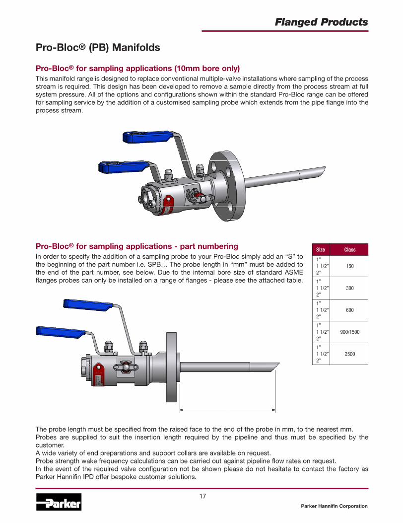
Pro-Bloc® for sampling applications (10mm bore only)This manifold range is designed to replace conventional multiple-valve installations where sampling of the processstream is required. This design has been developed to remove a sample directly from the process stream at fullsystem pressure. All of the options and configurations shown within the standard Pro-Bloc range can be offeredfor sampling service by the addition of a customised sampling probe which extends from the pipe flange into theprocess stream.
Pro-Bloc® for sampling applications - part numberingIn order to specify the addition of a sampling probe to your Pro-Bloc simply add an “S” tothe beginning of the part number i.e. SPB… The probe length in “mm” must be added tothe end of the part number, see below. Due to the internal bore size of standard ASMEflanges probes can only be installed on a range of flanges - please see the attached table.
The probe length must be specified from the raised face to the end of the probe in mm, to the nearest mm.Probes are supplied to suit the insertion length required by the pipeline and thus must be specified by thecustomer.A wide variety of end preparations and support collars are available on request.Probe strength wake frequency calculations can be carried out against pipeline flow rates on request.In the event of the required valve configuration not be shown please do not hesitate to contact the factory asParker Hannifin IPD offer bespoke customer solutions.
SSiizzee CCllaassss
1”1 1/2” 1502”
1”1 1/2” 3002”
1”1 1/2” 6002”
1”1 1/2” 900/15002”
1”1 1/2” 25002”
IMPORTANT NOTES
All non wetted parts will be supplied in standard stainless steel for exotic materials. For carbon steel construction trim materials will be supplied instainless steel.For flange to flange construction when the required flanges are different sizes then specify both sizes in section 3 example: 1st flange 1” pipe (16), raisedface (F), class 900 (900), 2nd flange 1/2” (8), raised face (F), class 900 (900) insert: 16F9008F900. Consult factory for available combinations.Ring type joints (T) CANNOT be supplied for 1/2” & 3/4” class 150 flanges.St. St. grades 302 and 304 are NOT used in the construction of any of these products.For customer specific options not covered here engineering will allocate a part number at quotation stage.Certification requirements and customer specifications MUST be provided at enquiry and order stage.For API flange requirements full details must be specified separately.Part number example PBY100B32T2500F Pro-Bloc - Flange by screw - Double Block and Bleed - Block (Ball) Bleed (Needle) Block (Ball) (PBY100) - 316St. St. construction (B) - 2” Pipe flange, Ring type joint, class 2500 (32T2500) - 1/2” female NPT outlet - 1/2” Female NPT vent - Firesafe design andcertified (F), all valves PTFE packed, ball seats PTFE, needle valve metal seated 17-4PH st.st. tips.
When selecting products for specific applications usersshould refer to our notice at the bottom of page 19.

Pro-Bloc® (PB) Manifolds
Hi-Check non-return valveThis high integrity full bore non-return valve eliminatesthe risk of back flow out of the process stream. Thedesign utilises a spring loaded poppet to ensure leakproof performance. The Hi-Check Non Return Valve isdesigned for higher flow and low pressure drop acrossthe valve - having a larger through bore than mostother manufacturers equivalent product.As standard a viton seal will be supplied with a “crack”pressure of 10 psig. A wide variety of seat materialsand crack pressures are available on request.In the event of the required valve configuration notbeing shown please do not hesitate to contact thefactory as Parker Hannifin IPD offer bespoke customersolutions. See Catalogue 4190-CV for more details.
Pro-Bloc® for injection applications -part numberingIn order to specify the addition of an injection probeand non-return valve to your Pro-Bloc simply add a “J”to the beginning of the part number i.e. JPB… Theprobe length in “mm” must be added to the end of thepart number, see below. Due to the internal bore size ofstandard ASME flanges probes can only be installedon a range of flanges - please see the table in thesampling Pro-Bloc section (previous page).The probe length must be specified from the raisedface to the end of the probe in mm, to the nearest mm.Probes are supplied to suit the insertion lengthrequired by the pipeline and thus must be specified bythe customer.A wide variety of end preparations and support collarsare available on request.Probe strength wake frequency calculations can becarried out against pipeline flow rates on request.
Pro-Bloc® for injection applications (10mm bore only)This manifold range is designed to replace conventional multiple-valve installations where injection into theprocess stream is required. This design has been developed to inject directly into the process stream at fullsystem pressure. All of the options and configurations shown within the standard Pro-Bloc range can be offeredfor injection service by the addition of a customised injection probe which extends from the pipe flange into theprocess stream. Pro-Bloc’s for injection applications include an injection probe which enables the fluid to beinjected directly into the process stream and a high integrity full bore non-return valve to eliminate the risk of backflow out of the process stream.
Parker Hannifin Corporation
18
Flanged Products
Notes
Parker Hannifin Corporation
Flanged Products
19
All dimensions shown in this catalogue are approximate and subject to change.
WARNINGFAILURE, IMPROPER SELECTION OR IMPROPER USE OF THE PRODUCTS AND/OR SYSTEMS DESCRIBED HEREIN OR RELATED ITEMS CAN CAUSE DEATH, PERSONAL INJURYAND PROPERTY DAMAGE.
This document and other information from Parker Hannifin Corporation, its subsidiaries and authorized distributors provide product and/or system options for further investigation byusers having technical expertise. It is important that you analyze all aspects of your application and review the information concerning the product or system in the current productcatalog. Due to the variety of operating conditions and applications for these products or systems, the user, through its own analysis and testing, is solely responsible for making thefinal selection of the products and systems and assuring that all performance, safety and warning requirements of the application are met.
The products described herein, including without limitation, product features, specifications, designs, availability and pricing, are subject to change by Parker Hannifin Corporation andits subsidiaries at any time without notice.
Offer of SaleThe items described in this document are available for sale by Parker Hannifin Corporation, its subsidiaries or its authorized distributors. Any sale contract entered into by Parker willbe governed by the provisions stated in Parker’s standard terms and conditions of sale (copy available upon request).

Parker Hannifin plcInstrumentation Products DivisionRiverside RoadPottington Business ParkBarnstaple, Devon EX31 1NPEnglandTel: +44 (0)1271 313131Fax: +44 (0)1271 373636Email: [email protected]/ipd
Parker Hannifin CorporationInstrumentation Products Division1005 A Cleaner WayHuntsville, AL 35805USATel: (256) 881-2040Fax: (256) 881-5072www.parker.com/ipdus
TTP 11/05