Embed Size (px)
Citation preview

M~C F1 LE CORY
DOTFA/CT8644Digital SystemFAATICHICL EN~nBus Integrity
toDonald EldredgeEllis F. Hitt
00
Columbus Divson505 King AvenueColumbus, Ohio 43201
March 1987
This document is available to the U.S. publicthrough the National Technica InformationService, Springfield, Virginia 22161.
Appiod tot public releGS61 lI
pwitsiution Uuuiited ~~T
88 1

~DOT/FAA/CT- 86/44 1oIRcews ~aa o
Digital System Bus Integrity12-19A
7. Author(s) .Performng Orpnzation Repar Pi.
Donald Eldredge, Ellis F. Hitt DOT/FAA/CT -86/44__________________________________________________ 10. Wart UuWt No.
I fttarm" YW a IUIoI NoYI Mi Ad&=U NAS2-11853Lockheed-Georgia Company 11. cotato kr DMarietta, GA 30063
13. Type 0 Report and Pertod Cboered
S?'-r~1T-n:Or trckafpor tat ion Contractor ReportFederal Aviation Administration Technical Center 14. Swpornq Agmcy CfAtlantic City Airport, New Jersey 08405
I&. SWVi'emunWV NamiPoint of Contact: W. E. Larsen/MS 210-2
Ames Research Center
This rep rt s mma izes andMoffett Field, CA 94035
t _hisreprtsumaries nddescribes the results of a study of current oremerging multiplex data buses as applicable to digital flight systems, -
particularly with regard to civil aircraft. Technology for pre-1995 and post-1995 timeframes has been delineated and critiqued relative to the requirementsthen envisioned. The primary emphasis has been on assured airworthiness of themore prevalent type buses, with attention to attributes such as fault tolerance,environmental susceptibility, and problems under continuing investigation.Additionally, the capacity to certificate systems relying on such buses has beenaddressed.
17 Key WOvdi ISuggnted by A~thiavs)) Is. O'Sulbution stateft..nt
Avionics, Bus Architecture, Bus Topology,Digital Flight Systems, Fault Tolerance, UnlimitedMUTX Buses, Networks, Protocols, Require- Subject Category 38ments, System Integration e, / - ~,~
9 ser 0 ...' Oa .o 00 s 'e Til 20 Stc ? v clats (C#IN Do !1 0 4P 2 -ce
Unclassified IUnciassified%a # -) %a- jpa Tej1.C#1 .-~. c -,' e-d . 21

TABLE OF CONTENTS
Page
1.0 INTRODUCTION 1
1.1 Definition of Integration Requirements 2
2.0 BACKGROUND 4
3.0 OBJECTIVE AND SCOPE 6
3.1 Overall Objective 6
3.2 Scope 6
3.3 Integration Impact 7
4.0 PRELIMINARY ARCHITECTURE CONSIDERATIONS - DATA BUS STRUCTURES 9
5.0 TOPOLOGY ALTERNATIVES 13
6.0 TOPOLOGIES 21
6.1 Review of Protocols 27
6.1.1 Collision Detection 28
6.1.2 Time Slots 31
6.1.3 Token Passing 33
7.0 DATA BUS CHARACTERISTICS 37
8.0 BUS PERFORMANCE CHARACTERISTICS 57
9.0 FAILURE MODES AND EFFECTS (BUS ARCHITECTURES) 63
10.0 FIBER OPTIC DATA BUS FOR AVIONICS INTEGRATION 74
11.0 IMPACT ON CERTIFICATION CRITERIA 85
Accesion ForNTIS CRA&IDTIC TAB 0Una,o' ,id [_]
Just! c.,t O ..... ... .. .
By INSPECT.. .
Di-. t
I I

LIST OF FIGURES
Page
Figure 4-1 Preliminary Architecture Overview 10
Figure 4-2 Sensor, Systems, and Management Bus Interconnections 12
Figure .5-1 Typical Avionic Hierarchical and Parallel 14Architectures
Figure 5-2 Integration Concepts Using Parallel Avionics 15Architecture
Figure 5-3 Integration Concepts to Flight Critical Subsystems 17
Figure 7-1 Waveforms Generated by Five Different Encoding 40Schemes for a Fixed Binary Signal
Figure 7-2 Data Bus Network Topologies 42
Figure 8-1 Data Latency Illustration in Hierarchical 59Architecture -
Figure 9-1 Simple Fault Tree Example 67
Figure 9-2 Single Channel-Dual Output (Buses A and B) Bus 72Control
iii

LIST OF TABLES
Page
Table 1-1 SUMMARY OF BUS CHARACTERISTICS 4
Table 5-1 COMPARISON OF HIERARCHICAL AND PARALLEL AVIONICS BUS 13ARCHITECTURE
Table 5-2 MEASURES-OF-MERIT 19
Table 5-3 ATTRIBUTES 20
Table 6-1 CRITERIA DEFINITIONS 22
Table 6-2 ALTERNATIVE TOPOLOGIES AND PROTOCOLS 26
Table 7-1 DATA BUS CHARACTERISTICS 37
Table 7-2 IMPORTANT PARAMETERS OF ENCODING TECHNIQUES 39
Table 7-3 MIL-STD-1553B DATA BUS CHARACTERISTICS 45
Table 7-4 CHARACTERISTICS OF MIL-STD-1773 DATA BUS 46
Table 7-5 ARINC 429 DATA BUS CHARACTERISTICS 48
Table 7-6 ASCB DATA BUS CHARACTERISTICS 49
Table 7-7 COLLINS SERIAL DIGITAL BUS CHARACTERISTICS 50
Table 7-8 BOEING DATAC BUS CHARACTERISTICS 52
Table 7-9 SAE LINEAR TOKEN BUS CHARACTERISTICS 53
Table 7-10 SAE HIGH SPEED RING BUS CHARACTERISTICS 55
Table 9-1 DIGITAL DATA BUS SYSTEMS FAILURE MODES AND EFFECTS 65
Table 9-2 FAILURE CLASSES 68
Table 9-3 TYPICAL ERROR-CORRECTION TECHNIQUES 69
Table 9-4 POTENTIAL FAILURES RESULTING IN LOSS OF BUS CONTROL 73SINGLE CHANNEL - DUAL OUTPUT (BUSES A AND B)
Table 10-1 OPTICAL BUS TECHNOLOGY LIMITS 76
Table 10-2 CONCERNS AND ISSUES 77
Table 10-3 STAR-COUPLED NETWORK LOSSES 84
v

DIGITAL SYSTEM BUS INTEGRITY
1.0 INTRODUCTION
Digital buses and microprocessors are used extensively in the current
generation of civil aircraft. These buses and processors are used in flight
control and avionics applications to transfer data and to perform complex
calculations. The Federal Aviation Administration (FAA), at the present
time, has no published criteria or procedures for evaluating these complex
systems. Currently, the databases and information necessary to develop the
regulations, criteria, and procedures required to certificate these systems
are not available.
Furthermore, digital systems in the next generations of civil
aircraft will require interconnect using digital bus architectures which will
be required to have revised interface standards, specifications and
architectural considerations in order to provide data to central and remote
processors. These digital buses will interconnect microprocessors, sensors,
and servomechanisms using diverse network topologies in order to increase
their fault tolerant designs and interfaces.
New aircraft incorporating advanced avionic systems/subsystems, will
require new concepts in data transfer to accomplish total system integration.
The next generation transport aircraft will need total airframe/system
integration (on a fulltime/full authority basis) which means new approaches
must be developed for the interconnection of avionic subsystems to ensure the
integrity of the data at all times. The development of a standard,
characterizing a higher order data and information transfer system for
interconnecting avionics system, which meets the above requirements, must
employ an operational protocol which provides high speed interconnect of
subsystems and common sensors, independence, and fault tolerance, as well as
distributed control of the common data bus at both the subsystem black box
level and the aircraft/mission level.

Future advances in aircraft basic flight control and integration of
other avionics subsystems accompanied by a need for total avionics system
integration will demand changes in both intra- and inter-subsystem data
transfers. These changes, which are due to many factors, include:
o Need to eliminate costly hardware/software elements required of
centralized controlled, data transfer systems.
o Dispersion of microprocessors within subsystems necessitating
the interchange of processed data between subsystems.
o Need for the generation of an aircraft database, available to
all subsystems, which includes all airframe/mission parameters.
o Maximizing the use of common sensor data and redundant data
sources.
o Making maximum use of multifunctional Control/Display (C/D)
elements.
o Allowance for further standardization of hardware/software
elements by use of other standards for interchangeability
between the avionic systems and aircraft.
1.1 Definition of Integration Requirements
Present day commercial and transport aircraft employ only single
level centralized controlled, command response type or direct-connect
undirectional, information transfer systems. The next generation aircraft
may have multiple information transfer systems which require interchange of
data and will communicate with one another through global memory storage
interface units. With systems/subsystems integrated in this manner, a"negative" change in one can result in erroneous data and information being
propagated throughout the entire system.
A solution to this potential problem is the development and use of aninformation transfer system which will efficiently interconnect in a
hierarchical order multilevel multiplexed buses and bus architectures. With
such an approach, software intensive fault-tolerant executive/operating
systems can be created which provide the processing of functions required of
multisubsystem inputs within the "local" terminals. Such a high speed
higher-order transfer system will probably employ contention or token-passing
2

(DATAC)ARINC MIL- CSMA TOKEN429 1553B ASCB CD PASSING
Maximum Bit Rate lOOK IM 667K IOM-20M 1OM-20M
Bidirectional No Yes Yes Yes Yes
Bus Controllers No Yes Yes No No
Defined Data Formats Yes No Yes Yes Yes
Low Cost Components No No Yes Yes NoNo
TABLE 1 SUMMARY OF BUS CHARACTERISTICS
In addition to controlling the flight control and avionics functions
of the current and next generation aircraft, the system designers are
beginning to incorporate multiplexed "utilities Systems Management" buses in
the design of the next generation aircraft. These utility buses will be used
to process and send data and information related to Powerlant, Hydraulic,
Fuel, Environmental Control, Secondary Power and Electrical Power functions
within the aircraft interconnected by redundant buses operating in the 1-10
Mhz range. These utility buses will be operated independently of the Flight
Control and Avionics buses; however, they will be controlled by the Master
Executive Software resident in one or more Local Area Networks or Token
Passing Networks.
2.0 BACKGROUND
The current generation of microprocessor based flight control and
avionics systems (as represented by the Boeing 757/767, the Lockheed LI011-
500, and the Airbus A310/A320) use bus architectures based on either the
ARINC 429-5 or the MIL-STD-1553A/B specification and standards. These buses
use shielded-twisted pair wires for the transmission media and interconnect
to microprocessors (which primarily use bit slice processors) which provide
4

protocols which will provide each active unit within the information transfer
system structure with the capability of structuring its own functionally
isolated communications medium whenever data interchange is required.
The extensive use of existing bus structures has proven the concept
of multiplexed data transfer systems to achieve a degree of integration.
Unfortunately, current protocols and architectures do not provide the
characteristics needed to efficiently operate with the next generations of
hierarchical/multilevel networks. The present systems characteristics are
ideally matched to many intra-avionics subsystems data transfer requirements
which necessitate sensor data collection, central processing, then
distribution of results to peripheral areas. There will be and should be
continued use of bus networks for the intra-subsystem data transfer.
In the next decade, we can expect some of the more common subsystems
to be combined in logical units (boxes) and the emergence of new subsystems
or groups of architecturally related functions to be implemented as common
units. Each of the major systems/subsystems will also be integrated with
each having its own unique intra-multiplexed topological (bus) network. Each
of these asynchronous information transfer functions and topological networks
must then be interconnected, using high bandwidth buses to create integrated
data and management bases from which information flow can be directed and
managed.
Such databases, when created, will result in the maximum use of
common data and allow for continuing changes in the subsystems and total
airframe/mission (flight phase) tasks with minimal disturbance (or
perturbation) of the higher-order information transfer functions.
Table 1-1 summarizes the characteristics of the avionics buses in use
today, along with the two ETHERNET-type buses currently in use in the
computer networking industry. While none of the entries have all the
qualities desired for the next generation, the newer network buses offer the
greatest potential in light of where the state-of-the-art will be by the time
that the next generation of "all new" airframes and avionics are available.
At the present time, data and information for avionics systems
integration can be successfully transmitted using these existing or other
proposed bus structures. However, each bus has its own limitations which
must be considered when assessing the airworthiness of the system.
3
the required internal processing speed (7-14 MHz clock rate) and the inherent
reliability and flexibility required for flight essential/flight critical
control systems. In this generation of digital systems, the individual
processors are run in a bit or frame synchronized manner, and the data are
exchanged between redundant computers via dedicated serial buses (either wire
or fiber optic); and internally by high speed dedicated transfer
buses/backplanes.
The next generation of flight control and avionics systems
architectures will change dramatically and will be characterized by multiple
microprocessors in each computing channel with more local processing within a
processor and the transfer of preprocessed data within the bus network. Inaddition, the system architectures will make use of 16/32 bit microprocessors
which will use high speed backplane buses (running at 20-50 MHz) for internal
(processor-to-processor) interfaces and exchange of data and information.
Furthermore, these processors and their fault-tolerant designs will make use
of global memory and functional partitioning of executive and applications
software to dccrease the complexity and increase the reliability of the
system.Furthermore, the transfer mechanism, as represented by the avionics
bus architecture (including the attendant controllers and terminal
interfaces) and its transmission media (wire or fiber optic) will play an
increasingly more important role in the integration and redundancy management
associated with the architecture of the system. The interface circuitry,
whether it is implemented using LSI/VLSI chips, or dedicated modules, will be
controlled by one or more processor modules and will be implemented in
redundant configurations to increase the reliability of the data transfer
system.
It is possible, with the ongoing technology developments, to develop
a single string physical module which has dual, triple and/or quadruplex path
capability and can exist as an integral part of the processor module. This
capability, combined with ongoing microprocessor development and advances in
internal/external fault-tolerant bus architectures provides the basis for the
development of highly integrated, highly redundant, highly survivable
computer network architectures in the framework of the digital "all electric"
aircraft of the 1985-1995 and 1995-2010 time frames.
5

3.0 OBJECTIVE AND SCOPE
3.1 Overall Objective
The overall objective of this effort was to conduct an evaluation
(through literature search and limited case studies) to determine current and
near term Airworthiness/Safety/Structural issues related to the
implementation of Digital Bus Architectures in Commercial, Business and
General Aviation aircraft in the 1986-1995 and 1995-2010 time frames. The
objectives of these evaluations (or case studies) were to provide data and
information on the potential airworthiness/safety/structural issues
associated with the increased utilization of digital buses in flight control,
avionics and utilities architectures in current, retrofit and new design
commercial, business and general aviation aircraft of the 1985-1995 time
frame; and to extend the FAA's knowledge of the potential
airworthiness/safety structural issues associated with the planned
implementation of the more advanced architectures in a later time frame. Of
special interest, in these studies, was an assessment of the impact of the
level of fault-tolerance (including provisions for the effects of electrical
disturbances, upsets and interference mechanisms - conducted or radiated) on
the integrity of the digital data being generated and transmitted for various
bus types and architectures.
3.2 Scope
The emphasis of the study was on the methodologies used to insure the
validity of data on buses which use shielded-twisted pair and/or coaxial
cable as the data transmission media for data transfer. Fiber Optic cable
media is also of interest, especially for the 1995-2010 time frame.
Initially, it was not a major consideration for this study, however, due to
the recent technological advances and developments in this area, the fiber
optic bus/bus characteristics are included in this report.
II

3.3 Integration Impact
Numerous advantages have been postulated relative to the integration
of certain aircraft subsystems (e.g., avionics, flight controls, propulsion,
etc.). Such advantages include reduction in crew workload, enhancement of
aircraft performance and capability, increased hardware efficiencies and
improved flight safety. Examples of integration which provides improved
flight safety and reduced pilot workload are autoland systems, flight
envelope limiters, and multimode controls.
Traditionally, there has been considerable independence in the design
of these subsystems, and components such as sensors were separately provided
for each subsystem. However, advanced aircraft designs often require that
these systems have significant interaction and have a common data source.
The combination of the need to functionally integrate these systems and the
desirability of avoiding unnecessary duplication of hardware provides the
impetus for developing integration techniques and supporting architectures
which both reduce overall costs and increase performance.
Since the avionics and flight and propulsion (as a minimum) are
expected to be implemented digitally in current and future aircraft,integration of these systems will probably use one of the buses and/or bus
structures, identified in the report, to provide inter-system communication.
This method of implementation will allow the necessary sharing of data
between subsystems. The desirability to maximize data availability between
subsystems is, however, in conflict with the need to isolate these systems
from propagation of failures from one system to another. Therefore, the
integration solution must consider the balance between the need for and type
of integration, versus the flight-safety and mission-criticality of each
subsystem as it applies to various architectural implementations within the
different aircraft configurations and applications.
The overall advantage of integrating flight-critical subsystems
(flight and propulsion controls) with other avionics subsystems can be
realized only if efficient, safe and practical methods of subsystems
communication can be implemented. Involved in the considerations are
architecture topology, design of the bus interfaces, interaction with thehost processor (controller) and data bus interface, bus protocol,
7

hardware/software failure modes, fault propagation potential, and protection
mechanisms that prohibit fault introduction or allow detection and management
of faults.
8

4.0 PRELIMINARY ARCHITECTURE CONSIDERATIONS - DATA BUS STRUCTURES
The bus structure for a prototype preliminary architecture (shown in
Figure 4-1) is a multilevel concept composed of four (4) digital information
transfer bus structures (Sensor, Management, Systems, Actuator) and one or
more dedicated analog bus structures. The Sensor bus contains data that are
time critical and necessary for critical system functions and includes:
o Body accelerations and angular rates
o Attitude angle and rates
o Navigation and position (angles and deviations)
o Pilot inputs (column, wheel, throttle, etc.)
o Surface position (deflections and accelerations)
The data handled by the Management bus are, for the most part, non-
time-critical data that provide control information and system configuration
and include:
o Pilot selected parameters and modes
o Initialization data
o Reference angles
The Systems bus transfers time-critical data that are provided (by
the aircraft avionics and flight controls systems) at a constant update rate
to perform mission/flight-phase oriented and automatic functions and include:
o Auto-throttle position and rates
o Autoload (deviations, deflections and commands)
o Attitude reference/control
o Flight management functions
o Pneumatic (status/control)
o Fuel (flow/rate, quantities)
The Actuator bus provides the necessary constant update rate data to
command and feedback control to the surface controllers and tactile attitude
warning devices and includes:
o Deflection Command/Activator Position (aileron, rudder,
elevator, spoiler, stabilizer, etc.)
o Stability Augmentation (gains/deflections)
o Stick Shaker
9

Hot alogSecondaryflighAnalog actuators
Outboard
* InboardFlight aileronVV n p i e n ta - U
Air data grou
BodyprocssorR udder
Sensor Systems 0
seso 01- u Id .1tiIUUUIU Stc
sensorctats 5h ke
00abu A bbssC
MIL 0
-OM Acuao shialkertatrbu 0
Margannts-
En nel Aae m uitio-en oro sta mtus le
Major oto acanels
100
-_ 0

The Analog (hard-wired) interconnections handle the flight essential
functions and include:
o Pitch rate sensors
o Pilot flight controls
o Redundant activators
In general, the prototype multi-level, multi-bus architecture for the
next generation commercial aircraft integrates the system functions by data
information transfer buses, while separating those functions into smaller
functional processing units; and by sharing sensors, decentralization of top-
level functional processing covering several computing elements, and by
separation of functions by criticality, which results in simplification of
system software through greater hardware complexity. Figure 4-2 shows some
of the potential bus interconnections that would be implemented for prototype
SENSOR, MANAGEMENT, and SYSTEMS buses in the next generation commercial
aircraft.
11
" .... .-. ..-. : , '/ "" y "' "~ "" "" N"" .... " 7°

L 0U
ziKL, R NR
0Lfil M t IL
.11,W 'FE LJ
III fil

5.0 TOPOLOGY ALTERNATIVES
In addition to the prototype architectural considerations discussed
above, there exist structural topology alternatives to the implementation of
the information transfer buses. Topologically, these buses can be organized
as an hierarchical architecture or as parallel architecture as shown in
Figure 5-1. In the context of integration with the various avionics and
flight control systems/subsystems, different alternatives are available
within each of the two bus architectures/structures as shown in Figure 5-2.
For example, with the hierarchical avionics bus architecture, the integration
can be performed using either a Local Bus or an Avionics System Bus. The
parallel avionics bus architecture supports integration over a single bus or
multiple buses. Table 5-1 summarizes the advantages/disadvantages of each
approach.
Hierarchical Avionics Bus Parallel Avionics Bus
Architecture Architecture
o Local Bus o Single Bus
o Minimum data latency o Simpler
o Lowest Intersystem o Greater flexibilityimpact
o Greater isolation
o Avionic System Bus o Multiple Buses
o Information required o Higher reliabilityat more than one local levelsbus
o Highest inter-/intra-system impact
o Greater data latencies
Table 5-1 COMPARISON OF HIERARCHICAL AND PARALLEL AVIONICS BUS ARCHITECTURE
13
N

iia. I
4U
Ia
IIS
a.I-J
I Cz
I
1.14
(-)-
-01.14
C-)1.14
U ~I-.1! - C-)-
I4
U S II: Lfl
U 1.14
IC0LA..
U
I
ii II
I31

co"fICAL "sofI an PlTCL eVrf
""A
~~,YV. A.
AVISUC 944"D
40DOM LOCAL k SWARM. SW IA.
cft-G. SIIM' 'G.MWV CONTICA, S,",
C~PUOf a Way
* INlS WTIIAIN DATA an SMAL IN"tOATM"i DATA VA
a am floirau
FIGURE 5-2 INTEGRATION CONCEPTS USING PARALLEL AVIONICSARCHITECTURE
15
3, '

From the control system perspective, three integration alternatives
are possible as shown in Figure 5-3. All three cases make use of various
combinations of data bus structures (Sensor, Systems, Actuator and Analog)
previously referenced, and either use the Flight Control Computers (FCC) as a
buffer between the Avionics and Flight Control Systems or connect directly to
the control system bus(es) with other mission essential computers acting as
the buffer. In either case, the proposed architecture/topology and its
attendant integration must be defined in such a manner that either:
(a) isolation (in terms of fault propagation) is maximized by integration of
functions and sensor signal requirements through the utilization of redundant
avionics buses and dedicated buses to support avionics, flight control and
other mission dependent functions within the same bus structure (this
approach, however, requires higher levels of system/subsystem reliability to
satisfy flight safety requirements); or (b) data latency is minimized. By
use of separated structures in which critical sensor data co-exists with the
flight control and mission dependent computation function on the same bus,
and making optional use of existing sensor redundancy with critical sensor
data being placed (through multi-party techniques) across the information
transfer bus hierarchy, this approach reduces the reliability constraints on
each of the various system functions, however, it can introduce new potential
failure points into the flight control and mission dependent computation
functions due to the increased complexity.
In either case, the selection of a system architecture (including bus
structure, topology and integration concept) is based on the design
requirements and the preference of the system
designer/integrator/implementator. In the concept design phase, a number of
candidate architectural concepts, bus architectures, and topologies are
postulated, all of which are able to satisfy system requirements within the
constraints of the required performance, reliability and safety criteria
levels established by the relevant guidance documents (FAR's, Advisory
Circulars, and other accepted air worthiness practices). The selection of
the final design for the information transfer system will ultimately become a
function of selected system/subsystem components, required interfaces, time-
critical events/data and the various measures-of-merit attributes that drive
the integrator's decisions.
16

U)4
zz
go >-
I"I
IcI
ccJ
It.
w ~1... 0
I.. -
V)-
C) <)
nz
6-00
wU W
0- Z0
U U)

The measures-of-merit and the attributes (as presented in Tables 5-2
and 5-3) are guidelines to be used by the system designer/integrator to
assess the integrity of the proposed information transfer system (its
architecture, structure, protocol and integration complexity) and must be
considered in order to fully understand and assess the ultimate performance,
reliability, safety and air worthiness of the final design.
Table 5-2 presents a summary of the measures of merit and their
associated quantitative measures for evaluating a givenarchitecture/structure; and Table 5-3 presents a list of the desirable
attributes for information transfer system bus protocols which can be used to
quantitatively determine the most advantageous protocol to implement for the
envisaged architecture/structure.
18
I!~~1 % %j 1R

Measures-of-Merit Quantitative Measure
Flight Safety - ability to maintain Probability of loss ofcontrol of aircraft control
Mission/Flight Phase Reliability - Probability of loss ofability to satisfy mission mission/flight phaserequirements capability (i.e., Autoland,
etc.)
Maintainability - time required to Qualitativerepair and frequency of repair
Availability - ability to initiate Qualitativea mission or flight phase activity/function including full-time, full-authority system (i.e., FADEC, PAS,Envelope Limiting)
Flexibility - ability to accommodate Reconfiguration costchanges
Reconfigurability - ability to cuiflpute Dynamic reconfiguration timeor perform mission or flight phase or redundancy default (failfunction in presence of failures safe/fail safe)
Computational Capability - throughput Total instructions executedof system computers per second
Data Transfer Capability - ability Max data latency, % peakto send messages in a timely bus loadingmanner and in presence of failures
Pilot Interface - ability to provide Qualitativecognitive information to pilot
Cost- initial procurement and LifeCycle Cost
Table 5-2 MEASURES-OF-MERIT
19

Attribute Quantitative Measure
Fault Tolerance Probability of error occurring/Recon-figuration time; Probability of pro-pagation
Efficiency Available bandwidth
Simplicity Presence/Absence complexityComplexity metric rating
Data Integrity Probability of connect data transferNumber of retries
Synchronous/Asynchronous Time to respond to emergency messages/interruption
Adaptable to new tech- Qualitativenology
Technology Insertion
Similarity to existing Qualitativebus architectures/structures/protocols
Deterministic Qualitative
Table 5-3 ATTRIBUTES
20

6.0 TOPOLOGIES
In the process of selecting the proper architecture/structure
(whatever the application), the following key technology factors (presented
in Table 6-1) must be evaluated based on the complexity of system/subsystem
being designed/implemented.
o Geographical layout (less tl,an 1,000 meters in range)
o Transmission Topology (linear, ring or other structure)
o Transmission Median (twisted pair wire, coaxial cable (basehand/
broadhand), fiber optic)
o Operator type (asynchronous/synchronous)
o Traffic load utilization (burst/regulated)
o Maximum data rate (bits/second)
o Maximum number of nodes (terminals, interfaces)
o Maximum/minimum node-to-node separation
o Maximum number of data channels
o Transmission - delay restrictions (bounded/unbounded, deterministic/
probabilistic)
o Access - control scheme (token passing on collision - sense multiple
access with either collision avoidance/collision detection)
o Protocols and ISO layers
o Software requirements
o Maintenance, test and error detection/correction
o Safety issues/conditions (EMC/EMI, RFI, shielding and grounding)
o Transaction monitoring, control and testing (single/multiple data-
transmitting and/or data-receiving terminals/stations)
o Data, voice, video and/or inquiry operations
o Interactions with other topologies/networks within the same
architecture/structure
The technical analyses leading to a selection of a topology/protocol
for a given application requires that topologies, protocols, media
components, configurations all be analyzed in terms of the system/subsystem
constraints imposed upon the detailed system design, and the existing state
of technology in each of these areas. In general, a number of topologies and
21
40

Fault Tolerance
The capability to endure errors and/or failures without causing totalsystem failure. An important aspect of fault tolerance is recovery, whichincludes fault detection, fault containment, fault isolation, andreconfiguration. These are defined as follows:
* Fault detection - ability of a system to determine theoccurrence of erroneous operation.
* Fault containment - ability of a system to prohibit errorsand/or failures from propagating from the course throughout thesystem.
* Fault isolation - ability of a system to isolate a failure tothe required level so as to be able to reconfigure.
0 Reconfiguration - ability of a system to rearrange or reconnectthe system elements or functions to provide as near the samesystem level of operation as before a failure.
System Integrity
In essence, the degree to which a system is dependable. Systemintegrity will include the following areas:
" Monitorability - ability of the protocol to be viewed passivelyto allow observation of the dynamics of the protocol in action.
* Testability - addresses how well the protocol supportscompleteness of testing and facilitates repeatable orpredictable results.
Initialization - support initial configuration of a system oninitial powerup.
* Data Link Assurance of Receipt - support assurance of good datathrough the data link level.
Table 6-1 CRITERIA DEFINITIONS(table continues)
22

Throughput/Response
Measure of how well the protocol transfers data from one node's linklevel to another. Included in this criteria are the following:
* Effective Link Level Data Throughput - throughput of data fromdata link level to data link level. It is important todistinguish between actual user data throughput as opposed topercentage utilization or loading of the physical transmissionmedium.
* Data Latency - time delay through transmission node's data linkand physical layers and receiving node's physical and data linklayers.
Message Structure
Addresses issues regarding various capabilities and capacitiesdefined by a protocol relative to the structure of the messages the protocolis designed to handle.
Addressing Capacity - allows system address expansion directlyor indirectly.
* Broadcast Capability - allows messages to be transmitted to allterminals simultaneously.
* Block Transfer - mode to allow transfer of variable length datablocks.
" Content or Labeled Addressing - allow terminals to selectivelyreceive messages based on message labels or message identifiersas opposed to "receive" or "destination" terminal addresses.
Table 6-1 CRITERIA DEFINITIONS(table continues)
23
- ' .I

Flexible Network Control Strategy
Addresses how well the protocol leaves the system designer free toaddress his specific problem (design flexibility).
* Central Control - control from one master, whether stationary ornon-stationary.
* Distributed Control - concurrent control from multiple points inthe data bus -system.
* Support of Synchronous Messages - supports transmission of aseries of messages at a known a priori sequence and time or timeinterval.
* Support of Asynchronous Messages - supports allowing nodes onthe data bus to transmit a message whose time of transmission isnot known a priori. (Also issue of priority messages requiringimmediate access to the bus.)
Cost/Complexity
Takes into consideration nonrecurring and recurring cost areas,availability of hardware, firmware, and software from commercial sources asopposed to new development in each of these areas.
* Non-Recurring Hardware and Software Costs - cost and complexityof the design and development of the hardware and softwarenecessary to support the protocol.
* Recurring Hardware and Software Costs - cost of the elements inproduction needed to implement the bus system.
* Support Costs - cost to support the elements of the bus systemonce they are in the field.
* Support Costs - cost to support the elements of the bus systemonce they are in the field.
* Weight, Size and Power - measure of the costs needed to meet thephysical requirements of the data bus elements.
Table 6-1 CRITERIA DEFINITIONS(table continues)
24
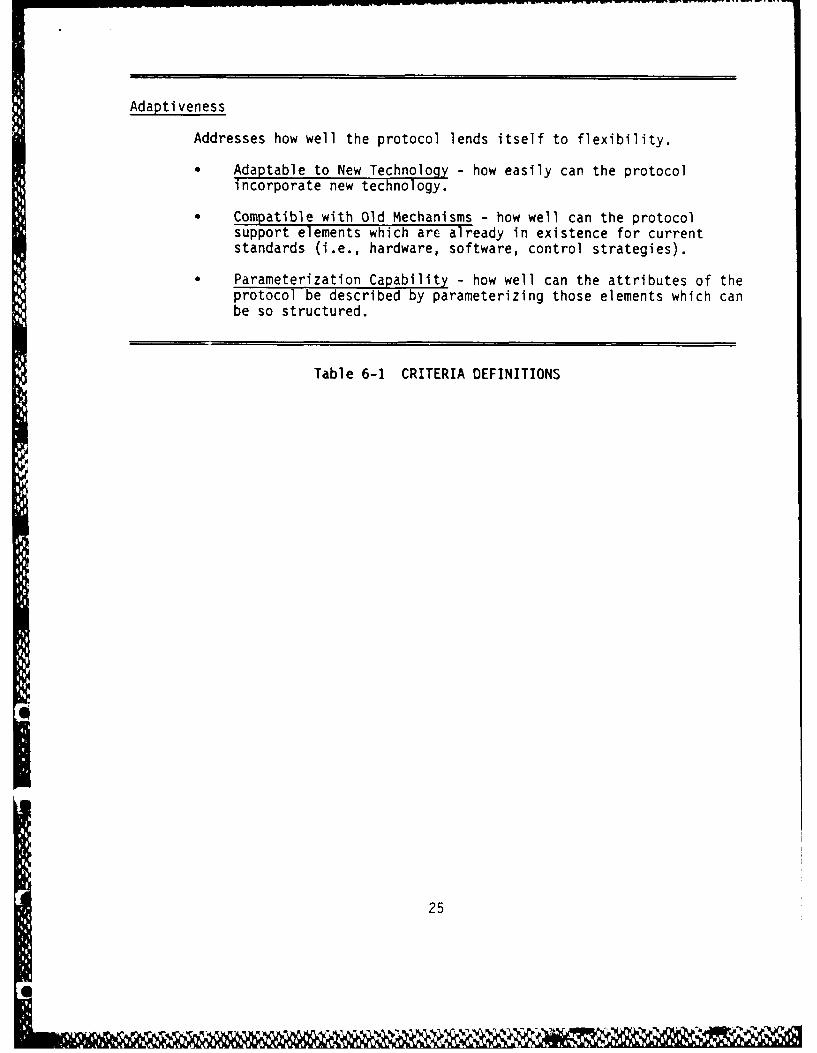
Adaptiveness
Addresses how well the protocol lends itself to flexibility.
" Adaptable to New Technology - how easily can the protocolincorporate new technology.
" Compatible with Old Mechanisms - how well can the protocolsupport elements which are already in existence for currentstandards (i.e., hardware, software, control strategies).
* Parameterization Capability - how well can the attributes of theprotocol be described by parameterizing those elements which canbe so structured.
Table 6-1 CRITERIA DEFINITIONS
25

protocols currently exist, the most common/applicable to commercial transport
implementation are presented in Table 6-2. As can be seen from Table 6-2,
the choices for protocols are highly dependent upon the Topologies.
TOPOLOGI ES PROTOCOLS
COMMAND CSMA/CD TOKEN INSERTION TIME REQUEST STORERESPONSE PASSING ACCESS SLOT &
FORWARD
Linear Bus X X X X
Star X X X X
Fully X X X XConnected
Ring X X X
Swi tched X X
Table 6-2 ALTERNATIVE TOPOLOGIES AND PROTOCOLS
Two of the above Topologies have explicit capabilities which are
reflected in the planning for the next generation commercial transport
information transfer system: The Linear Bus and the Ring Bus
architectures/structures. A third possibility, not included in the above, is
the currently implemented point-to-point instrumentation of the ARINC 429 Bus
structure.
26

period of interference from the second terminal. This brief signal is
attenuated as it returns to the first terminal and there is no clear guarantee
that it remains detectable. It is interesting that only ETHERNET anticipates
this problem and institutes the jamming pulse train to assure collision
detection.
Part of the ETHERNET literature points out another interesting case.
Often the carrier sense function is implemented by detecting the phase shift in
the waveform. But if multiple transmitter attempt to use the bus
simultaneously, it may result in current saturation, holding at a constant
level. A saturated bus then looks like an idle bus, effectively inviting other
terminals to join the traffic jam.
Collision detection in a fiber optics network is possibly an even more
difficult problem. The dynamic range of fiber optic receivers is already an
area of concern. The "listen-while talk" requirement of collision detection
adds the need to be able to handle the signal from the nearby (it's own)
transmitter and yet to be responsive to the distant signal from another unit.
It is also conjectured (in some of the literature) that fiber optic receivers
that are required to be on while the (necessarily close) transmitters are
functioning will have very short lifetimes, significantly impacting maintenance
and life cycle costs. (Note: this is the phenomenon that leads to the
suggestions of transmissive star couplers, a multi-fiber approach that
logically appears to be a bus structure). There exists, therefore, some
genuine doubt that a collision detection protocol can readily be transitioned
to fiber optic technology.
To summarize then, the analysis of collision detection protocols leads
to the conclusions that they require utilization be kept low in order to work
well; they may cause significant testing problems due to undetermined,
unrepeatable message sequences; and they may not be easily upgraded to new
technologies.
6.1.2 Time Slots
A time slot protocol is one in which the use of the transmission medium
is pre-allocated. Each of the terminals in the system knows the time it is
permitted to transmit and it waits for the time, takes control to transmit (or
30

distances. It can range up to many milliseconds in large networks or even
seconds in very complex communications systems.
The improvement obtained by using CSMA/CD is not quite as dramatic as
one might expect. While the potential for interference is reduced to the short
time of the collision window, a secondary effect of carrier sense is a tendency
to synchronize terminals. Since all terminals wait for a quiet network, there
is an increased likelihood they will attempt transmissions within the collision
window. This thinking suggests the next variation in the protocol. A time
interval, called a "mini-slot" is defined to be slightly larger than the
collision window. Based on some priority scheme each terminal waits some
number of mini-slots following the detection of a quiet network before
attempting to transmit. If a higher priority terminal exists in the network
it's transmission will begin in an earlier mini-slot and be sensed by the lower
priority terminal which will not interfere and simply reschedule its own
transmission for a later period of time.
To circumvent these problems, a random selection of mini-slots is used.
If a collision is detected the terminal "backs off" a fixed time interval and
reselects a mini-slot surrounding the targeted transmission time. Since the
terminals operate independently, two terminals which collide once will both
back off, select different mini-slots (with high probability) and be collision
free in their retransmissions. Should a second collision occur, the terminal
doubles its backoff interval and reschedules the message. In general, if n
collisions have occurred, the backoff interval is multiplied by 2n
The important factor to recognize is that the CSMA/CD protocol is
directed at a system of highly autonomous user terminals, a potential drawback
to this bus protocol for Avionics Systems interconnect.
Another characteristic of collision detection protocols is that message
sequences are necessarily uncontrollable, hence unrepeatable and therefore very
difficult to test.
A final consideration relating to collision detection protocols is that
the actual collision detection process itself may not be feasible. It was
indicated two transmitters would detect each others' transmission and both
backoff. But if in fact the signal from the first transmitter is just reaching
the second terminal when it begins to transmit, this terminal may quickly
detect the collision and abort his own. The result could be a very short
29
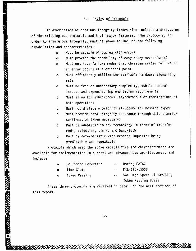
6.1 Review of Protocols
An examination of data bus integrity issues also includes a discussion
of the existing bus protocols and their major features. The protocols, in
order to insure bus integrity, must be shown to include the following
capabilities and characteristics:
0 Must be capable of coping with errors
o Must provide the capability of easy retry mechanism(s)
o Must not have failure modes that threaten system failure if
an error occurs at a critical point
0 Must efficiently utilize the available hardware signalling
rate
o Must be free of unnecessary complexity, subtle control
issues, and expensive implementation requirements
o Must allow for synchronous, asynchronous or combinations of
both operations
o Must not dictate a priority structure for message types
o Must provide data integrity assurance through data transfer
confirmation (when necessary)
0 Must be adaptable to new technology in terms of transfer
media selection, timing and bandwidth
o Must be deterministic with message inquiries being
predictable and repeatable
Protocols which meet the above capabilities and characteristics are
available for implementation in current and advanced bus architectures, and
include:
0 Collision Detection -- Boeing DATAC
o Time Slots -- MIL-STD-1553B
o Token Passing -- SAE High Speed Linear/Ring
a Token Passing BusesThese three protocols are reviewed in detail in the next sections of
this report.
27

6.1.1 Collision Detection
This protocol arises when the transmitting elements of a communications
network operate autonomously. There is a probability two or more will attempt
transmission at the same time, interfering (colliding) with each others' data
transfer.
In its simplest form, this protocol is implemented by letting each
terminal transmit whenever it wished. There are, however, a number of
inefficiencies associated with this approach. For example, if the data from at
least two transmitters is corrupted, it must be repeated in its entirety for
all transmitters. Even if a message is quickly repeated successfully the total
time to accomplish the transmission could easily be many times the original
message length. In addition, there arises the concern for the possibility of
repeated collision for a specific message or sets of messages.
Historically, implementations of this protocol have demonstrated that a
maximum of less than 20% utilization of the network bandwidth may be attempted
before the network stability is threatened. With higher loads, a second
collision for a message has a much higher probability. Once this does occur,
the total traffic from the first collision, plus that from the second is all
thrust down stream in the overall message traffic, increasing the likelihood of
additional collisions. In short, at some point the process begins cascading
until all terminals in the network become involved and no successful
transmissions can be performed.
Refinements of this protocol are numerous. With this protocol, the
situation is improved if the second transmitter is smart enough to detect the
presence of the first message and delay his own attempt. This approach is
known as carrier sense multiple access (CSMA) and when used in conjunction with
* collision detection is referred to as CSMA/CD which is the technique used in
the ETHERNET protocol and is similarly the basis for the DATAC protocol.
With CSMA/CD the occurrence of interfering transmissions is restricted
to that situation in which two terminals begin to transmit "so closely together
in time" that neither has yet sensed the other's signal. This short time
interval at the beginning of a message is referred to as the "collision windov'"
and is simply due to the propagation delay of the network. The collision
window is typically on the order of a microsecond in a wired network over short
28
Ir0I4t Ar ' rP

receive if the protocol permits this) completes its task and then relinquishes
control at the end of its time slot. This protocol approach is also known as
time division multiple access (TDMA), or sometimes as "pure TOMA" since the
time division is the only basis of control transfer identified in the original
statement.
This protocol is strongly synchronous. With a purely synchronous
application, all message sequences can be predefined in some optimum fashion.
Once a system wide time base is established the terminals can take their turns
managing the data flow assigned to them and the control transfer from one
terminal to the next can be as rapid as the clock resolution permits. In
principle, this protocol can approach 100% bus utilization. Time slotting is
highly fault tolerant in the sense that if a potential controller fails, the
system continues to operate with the other terminals performing data transfers
during their assigned slots. In effect the slot for the failed terminal just
goes blank.
The time slot protocol is less fault tolerant when individual message
errors are considered. The baseline definition makes no allowance for message
retry. If slots are fully assigned and tightly packed (i.e., designed for 100 ,
utilization) the protocol must explicitly prohibit message retry; message
errors are basically ignored.
This concern for message retry generates a first variation on the time
slot protocol. The slots are oversized relative to the message traffic
* required in order to reserve a certain fraction of time for message retries.
The penalty of course is reduced efficiency. The system designer can elect to
reserve enough time to allow all messages to be retried once. He does so
however only by driving the efficiency down to a 50% maximum.
In between these two extremes (100% use and 50% use) the system
designer may select whatever value is deemed optimum for his system. But now a
new concern arises. Once message retries are permitted, but time is not
reserved sufficient to retry all, there then exists the possibility of a time
slot overrun. To manage this problem, logic (probably software) must be added
to make determinations about extending the time slot or truncating message
retries in order to stay inside the assign time.
Extending the time slot requires now that the next potential controller
(and therefore all controllers) do something like monitor bus traffic prior to
31

initiating messages. On the other hand, truncating retries in order to
maintain the slots leaves the retry strategy less reliable. In short, there is
a basic message retry versus efficiency tradeoff to be made and system
complexity begins to rise as one moves away from the pure TDMA.
Time slots do not easily accommodate asynchronous message. First,
there is the question of allowing time for them. Like message retries, some
reserve allocation must be made. And again, either this allocation is very
generous (with considerable efficiency impacts) or else the time slot overrun
must be dealt with, introducing attendant complications.
Given the above, the response time when providing for asynchronous
messages is still not very good; that is, the emergency message is not well
handled. It must wait for the next available time slot in order to transmit
the message. This problem can be attacked by giving the source terminal
frequent short time slots. This, however, is just another way of allocating
reserved slot time and it has the same overall system effect.
Another variation on the time slot approach consist of dynamically
assigning the time slots. For example the last terminal in a major frame can
poll other system elements and plan the next set of slot assignments and
broadcast them to other terminals. This approach is much more responsive to a
dynamic environment and gives improved handling of emergency message. There is
more overhead involved and there are some unpleasant fault tolerance
implication. The dynamic slot assignment process becomes a single point of
failure and the message communicating the slot assignment becomes a critical
message; that is a message that must succeed in order for the system to
function correctly.
In summary, the strongly synchronous, very clearly defined time slot
approach offers outstanding performance for a highly synchronous system. As
deviations from that are accommodated by the protocol, efficiency impacts are
accumulated and control complications are introduced fairly rapidly.
6.1.3 Token Passing
This protocol consists of a terminal performing bus control to
accomplish its data flow requirements and at the completion of those
operations, sending a special message that transfers bus control to another
32

terminal in the system. This special message contains a data word called a
token identifying what terminal is to take control of the bus. The offering
terminal at the completion of his operations simply takes the token message as
he received it, adds one to the token value and sends out the message.
This elegantly simple control transfer mechanism accomplishes a number
of things more or less automatically. First, recognize that when the last
terminal to administer control completes its operations a token message is
formulated and sent out with a non-existent token number. No terminal takes
control, so there is a brief lapse in the data flow. That terminal currently
assigned token zero is charged with the responsibility of timing out on this
lack of bus activity and starting its own period of bus control. As noted
above when those messages are completed, control is then passed to token 1.
The protocol automatically restarts itself with token zero regardless of the
number of tokens currently active in the system.
A terminal coming on-line to an already active system simply has to
monitor the system for a few cycles to see what token message ends each cycle.
When no terminal responds to a specific token message, the terminal trying to
enter the network appropriates that token number for his own. On the next
cycle (or as many as needed to establish the correct token number with some
confidence) the terminal responds positively to the token message by initiating
his own set of messages and bus control functions. Since this is done
promptly, the token zero terminal does not restart the cycle until the new
terminal has completed operations, passed on the token, and no other terminal
responds to that.
With these defined mechanisms, consider now what happens when a
terminal suddenly fails. If part way through a cycle, the token is offered to
a terminal that has failed, the token is in effect, "dropped". No terminal
takes control and bus activity ceases. When this occurs, the terminal with
token zero functions as usual, detecting the lack of his activity and
restarting its own period of bus control. The failure of a terminal with a
given token causes all higher numbered tokens to be skipped. Logic in these
terminals is required to recognize and respond to this situation.
Recognition of this situation is a matter of the terminal timing out on
the interval since it last received control. When more than two full cycle
times have passed without the terminal receiving the token offer, it decides
@33
something has failed in the network. The response the terminal makes at this
point is to decrement its token number by one. On the next cycle the terminal"picks up" the "dropped" token and normal operation of this and higher numbered
terminals (which have performed the same process and decremented their own
tokens) may now resume. The network response to the failed terminal situation
is to run a few abbreviated cycles which effectively confirm the failure and
then to close the gap and resume normal operations without the failed unit.
When and if the unit recovers, it may attach itself at the end of the loop as
previously described.
It is to be noted that the above described mechanism works even for the
case of a failure of the token zero terminal. After a period of time, the
token one terminal discovers it is not being serviced, decrements its token to
zero and assumes the function of starting each cycle. This migration of token
number in response to failures implies that all terminals must have the
capabilities defined above for the token zero terminal.
The token passing protocol is designed to be highly fault tolerant of
controller failures and clearly has achieved that objective.
The approach does not, however, easily satisfy the requirements of a
synchronous system. The failure of a terminal in the loop causes the data from
that and all higher numbered tokens to simply stop for a while, and then resume
operation with a portion of the data flow missing. Subsequent recovery of the
terminal may reinstate the missing data but at a different place in the overall
cycle. The synchronous system practice of scheduling data flow and task
execution with a fixed time relationship would not be reliable.
To try to maintain such a relationship it would be necessary to handle
it somewhat like asynchronous tasks. That is, the data arrival could be
treated as an event which in turn could be used as a condition for task
execution. To accomplish this, software inspection of the data received might
be necessary.
Possibly with a careful system design, these problems could be avoided
by structuring a strictly receiver oriented message flow. But even then the
g implication remains that task processing can be reassigned on the time line.
This raises a system level iszue of whether the designed distribution of
processing loads can be maintained.
34
N

Neither does the protocol offer a good environment for managing
asynchronous operations. Basically, regardless of when the requirement for an
asynchronous message may arise, the terminal cannot transmit the message until
the token is passed to it. The response time provided asynchronous messages
will, in general, average half the total cycle time of the system. But since a
terminal can be skipped due to problems with another terminal, not even this
time can be guaranteed. A true emergency message, that is an asynchronous
message with a very short response time requirement cannot be handled by the
protocol. Some add-on such as frequent polling of the source of such messages
might be able to achieve the necessary response. Relatively large overhead
impacts may be expected in such an approach.
Another area of concern is the impact of errors on the token passing
process and vice-versa. It is to be noted that the time out executed by the
token zero terminal should be kept small in the interest of efficiency. This
time out interval, whatever it is defined to be also defines, necessarily, the
maximum time any bus controller may pause during its operations. Should a
controller, due to some special situation such as error analysis take too long
before its next bus operation there is the possibility that the token zero
terminal will interpret this as the end of a cycle and start the next cycle.
When the pausing terminal attempts to resume operations it will now
collide with the traffic from the token zero terminal. The normal result of
colliding terminals is that both believe they have failed. If this occurs the
entire system stops until the other controllers recognize the problem and
adjust their tokens. Even at this point the difficulty hasn't been resolved.
When the two failed terminals attempt to rejoin the network they will likely
collide again. Another possibility, depending on the relative timing in the
various terminals, is that one of these recovering terminals could mistake agap in the network for the end of the cycle. In this case it would appropriate
a token already in use and when it attempted to reenter operation it wouldprecipitate the apparent failure of yet a third terminal.
Another potential outcome of the original pair of colliding terminal is
that they succeed in establishing apparently normal operations but on separate
redundant buses. This eventuality would have less immediate failure impacts
but would lead to protracted erratic system operation with the problems
occurring at the individual message level.
35

. . .. .. . ... = , - ;=7 =- . . .. . . . . - W -; W-- - -a - - -. T ; - 7J - * . -- ; -
These kinds of considerations would probably lead to stretching out the
defined interval for the token zero time out and require some set of rules for
sampling bus activity prior to starting a new cycle. These factors along with
some estimates of overall system load would then need to be input to the
process of defining the time interval that each terminal would use in deciding
when to decrement its token. This would have to be sized for the maximum case
and more than likely this time interval would also have to be exaggerated in
the interest of caution.
A more pragmatic approach might be to rethink the token passing
handshake with a view to making it more ironclad and of detecting a dropped
token more quickly. Perhaps for example the message should be "terminal X
passing the token to terminal Y with terminal Z selected to validate theA-. handover". A procedure could be developed for terminal X and terminal Z to
cooperatively determine when terminal Y had failed. This information could
then be communicated to the rest of the system. In general, the more widely
*distributed the total system state information is, the more reliable the
overall operation.
,I.-
,'
hi

7.0 DATA BUS CHARACTERISTICS
Eight different data buses are either in use or under development for
aircraft. Table 7-1 presents characteristics which describe each of these
buses.
Transmission Media Logical AddressesCharacteristic Impedance Media AccessMain Bus Length Data Link Control ProtocolMedia Connection Error DetectionModulation SynchronizationSignaling Method Word SizeTransmission Direction Data Bits/WordTransmission Method Words/Message (Min.-Max.)Transmission Order Word TypesData Rate Intermessage Gap TimeDate Code Bus Frame LengthBit Error Rate Bus Control Transfer TimeWord Error Rate Terminal Transmit InterfaceTopology Terminal Receive InterfaceNumber of Terminals/Addresses
Table 7-1 DATA BUS CHARACTERISTICS
Transmission media include shielded twisted pair wire, coaxial cable,
and fiber optic cable. The characteristic impedance of the transmission
media is specified by the standard for each data bus. Restrictions on the
main bus length are determined by transmission line losses including those
due to connection of devices to the bus.
Modulation techniques and signaling method are related to the data
code category. Code is broadly categorized as single-density or double-
density. Double-density codes include delay modulation (DM), modified-
frequency modulation (MFM), group-code recording (GCR), zero modulation (ZM),
enhanced nonreturn-to-zero (ENRZ), and randomized nonreturn-to-zero (RNRZ).
Delay modulation, or Miller, coding requires at least one signal
transition for every two bit interval and has no more than one transition per
37

bit, still providing some synchronization capability, at a lower modulation and
bandwidth requirement.The most common single-density codes are non-return to zero (NRZ); NRZ-
inverted (NRZ-I), which is sometimes referred to as NRZ-M; NRZ-dual-level (NRZ-
L) ratio; and biphase. Biphase covers several subcategories: Manchester II,
frequency modulation (FM), and phase encoding (PE). Since these single density
codes are self-clocking, the clock is represented by level transitions, which
take place even if data transitions do not. NRZ, return-to-zero (RZ), and
biphase are categorized by the suffixes L (level), M (mark), and S (space). An
-L suffix indicates that data are represented by different levels; -M and -S
suffixes indicate that date are represented by the presence or absence of
transitions. In codes designated -M, a ONE (defined as a mark) occurs with a
level transition; ZERO is no transition. The converse is true for codes
designated -S.
NRZ codes remain constant throughout a bit interval and either use
absolute values of the signal elements or differential encoding where the
polarity of adjacent elements are compared to determine the bit value. This
method lacks independent synchronization and error-detection capabilities but
provides efficient usage of the bandwidth.
RZ codes return to a binary 0 level at one half the bit interval for
binary 1 signals, requiring a higher bandwidth for an equivalent NRZ data rate.
Biphase codes include the Manchester and Differential Manchester
techniques. At least one signal transitions is required every bit interval,
providing a self-clocking mechanism. The absence of the expected transitions
may also be used for error detection. With two possible transitions per bit
time, there is a corresponding increase in the bandwidth required.
Multilevel binary encoding schemes use more than two signal levels.
One method is bipolar, which has no synchronization capability but does provide
some error detection by requiring successive binary 'Is' to be of opposite
polarity.
Most of the aircraft data buses use biphase codes like Manchester II,
* which is self clocking since the data and clock are included in a single serial
data stream. In clocked systems, the clock defines the size of the data-bit
cell; however, in nonself-clocking systems, speed fluctuations cause the data
track to vary relative to the speed of the clock. Over a period of time, the
38eW-
04
it

clock will appear to speed up or slow down and improperly define a data bit
cell. With self-clocking, everything stays synchronized. The mid-bit
transitions of Manchester code help detect transmission errors.
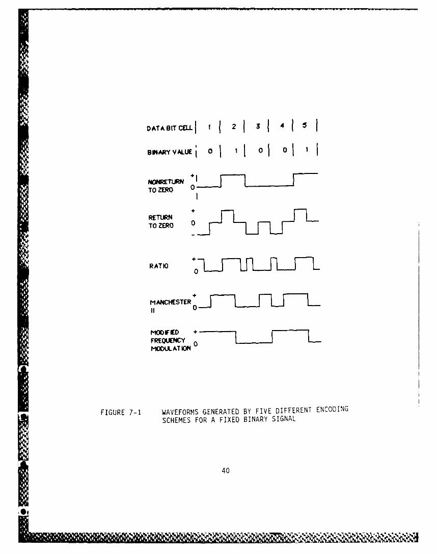
Table 7-2 summarizes the major features for some of the popular single
and double-density codes. The encoded waveforms in Figure 7-1 illustrate
patterns for an identical binary input produced by each form of encoding.
Band PreambleBandwidth Storage Self- DC Speed for
Code fl fh Efficiency Clocking Presence Ratio Synchronization
NRZ 0 O.Sf* 100% No Yes Infinite No
RZ 0.25f 1.Of 50% No Yes 4 Yes
S-NRZ 0 0.5f 80% No No J No
Rat o 0.75f 1.5f 33% Yes No 2 No
Biphase 0.5f 1.Of 100% No Yes 2 Yes
Double- 0.5f 100% No Yes 2 Yesdensity
*Bandwidth in terms of the fundamental frequency of the data rate.
Table 7-2 IMPORTANT PARAMETERS OF ENCODING TECHNIQUES
The transmission direction, method, and order define whether data is
transmitted and received over the same bus, whether the data transmission is
synchronous or asynchronous, and whether the most or least significant bit is
transmitted first.
39
4.. I.
DATA BIT CELLf 2 (3 4 1BINARY VALIUj 0~ 0~ 0~o
NONRETURNTO ZERO 0
RETURNTO ZERO 0
RATIO +0 -
MANCHESTER +
II 0
MODIFIED +FREQUENCY 0MODUL AT ION
FIGURE 7-1 WAVEFORMS GENERATED BY FIVE DIFFERENT ENCODING
SCHEMES FOR A FIXED BINARY SIGNAL
40

The data rate is the number of bits transmitted per second.
The bit error rate and word error rate are specified values which the
bus must meet continuously.
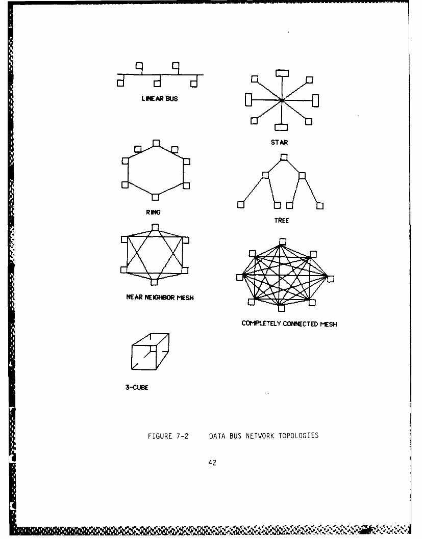
Topology is the architectural configuration of the data bus network.
Candidate topologies include the single linear bus (and additional redundant
buses), star, ring, tree, near neighbor mesh, completely connected, and the
n-cube (n=3) as shown in Figure 7-2.
Additional characteristics include the number of terminals or
physical addresses, the number of logical addresses, the method of media
access, the data link control protocol, error detection techniques used, and
method of synchronization of terminals connected to the physical media.
Two protocols enter into the design of a data bus system. The first
is the protocol associated with gaining access to the bus and control of data
transmission. The second is the data transmission protocol itself. Both
involve certain aspects of fault tolerance including error detection and
correction.
One of the control concepts to be considered is the bus
access/control transfer protocol. The three basic types are:
(1) dedicated access
(2) polling
(3) random access methodologies.
Dedicated access methods (Space Division Multiplexing (SDM),
Frequency Division Multiplexing (FDM), and Time Division Multiplexing (TDM))
permanently allocate each node a portion of the total transmission time.
SDM assumes that a physical line connects each node to a central
processor and is virtually contention free. FDM splits the frequency
spectrum into channels, which may be statically or dynamically allocated
0 among the nodes. TDM assigns each node a specific time slot during which it
has full access to transmit.
The detection of data bus access/control faults is usually embedded
in the bus access/control protocol. Watchdog timers and command/response are
favored design methods for detection of bus access/control faults. In
response to these types of faults, the recovery mechanism usually involves
either retransmitting messages, or switching to an alternate controller or
redundant data bus.
41
-!
L PEAR BUS
ST AR
RM4TREE
NEAR NEM3BOR M-ESH
COMPLETELY CONNECTED MESH
3-CUIBE
FIGURE 7-2 DATA BUS NETWORK TOPOLOGIES
42
Data transmission protocols include:
(1) character oriented - Binary Synchronous Communications
(BISYNC),
(2) character count - Digital Data Communications Message
Protocol (DDCMP), and
(3) bit oriented - Advanced Data Communication Control
Procedures (ADCCP), High Level Data Link Control (HLDLC),
and Synchronous Data Link Control (SDLC) methods.
The character or byte-oriented protocols use a code set which is
shared between both data and control functions; require special escape
functions to obtain data transparency; intermix device, message, and link
control; perform error checking only on text; and are somewhat rigid 'i
structure.
Bit oriented protocols use specific fields for control purposes,
freeing the code set for data (therefore making code naturally transparent);
perform error checking on both text and supervisory data; separate link
control from device and message control; and are quite flexible and modular.
The protocol must perform the functions of:
(1) initialization - sto;+up of idle communication lines,
(2) framing - determination of transmission block beginnings
and endings,
(3) link management control transmission and reception,
(4) sequence control - avoid duplicates, and request
retransmissions for lost or erroneous messages,
(5) flow control - regulate messages transmitted on the media,
(6) transparency - ability to treat all information as pure
data, and
(7) abnormal-condition recovery - to treat any illegal commands
or conditions.
In evaluating data transmission protocols, the error detection and
correction techniques which could be used by the data link layer of the
network include vertical redundancy check (VRC), longitudinal redundancy
check (LRC), and cyclic redundancy check (CRC). VRC appends one additional
overhead bit (a I or a 0) to a data word to implement either odd or even
parity. VRC does not detect double bit errors. LRC views a frame as a block
43

of characters, and appends an additional character consisting of the parity
bit for each bit position in the character. Even when used with VRC, some
patterns of even number errors remain undetected. CRC generates a frame
check sequence for a frame which is exactly divisible by some predetermined
number which may be checked at both ends of the transmission. Only rare
combinations of errors remain undetected with this system.
Forward error correction codes are used when the receiver alone
corrects data errors. The codes are calculated and transmitted along with
the data. For acceptable correction, data rates are reduced by at least 50%.
Backward error correction (retransmission) is used to resend messages
when the receiver signals the transmitter that an error occurred in the
transmi ss ion.
The number of bits in a word, number of words in a message, word
types, and the gap between consecutive messages are important
characteristics. Finally, the characteristics of interfaces to the media for
transmission and receiving of data are presented.
Characteristics of each bus are presented in Tables 7-3 to 7-10.
These characteristics are contained in a single data base which has been
* broken down into the individual buses for the purpose of presentation in this
report.
Table 7-3 presents the characteristics of the MIL-STD-1553 bus.
1 44
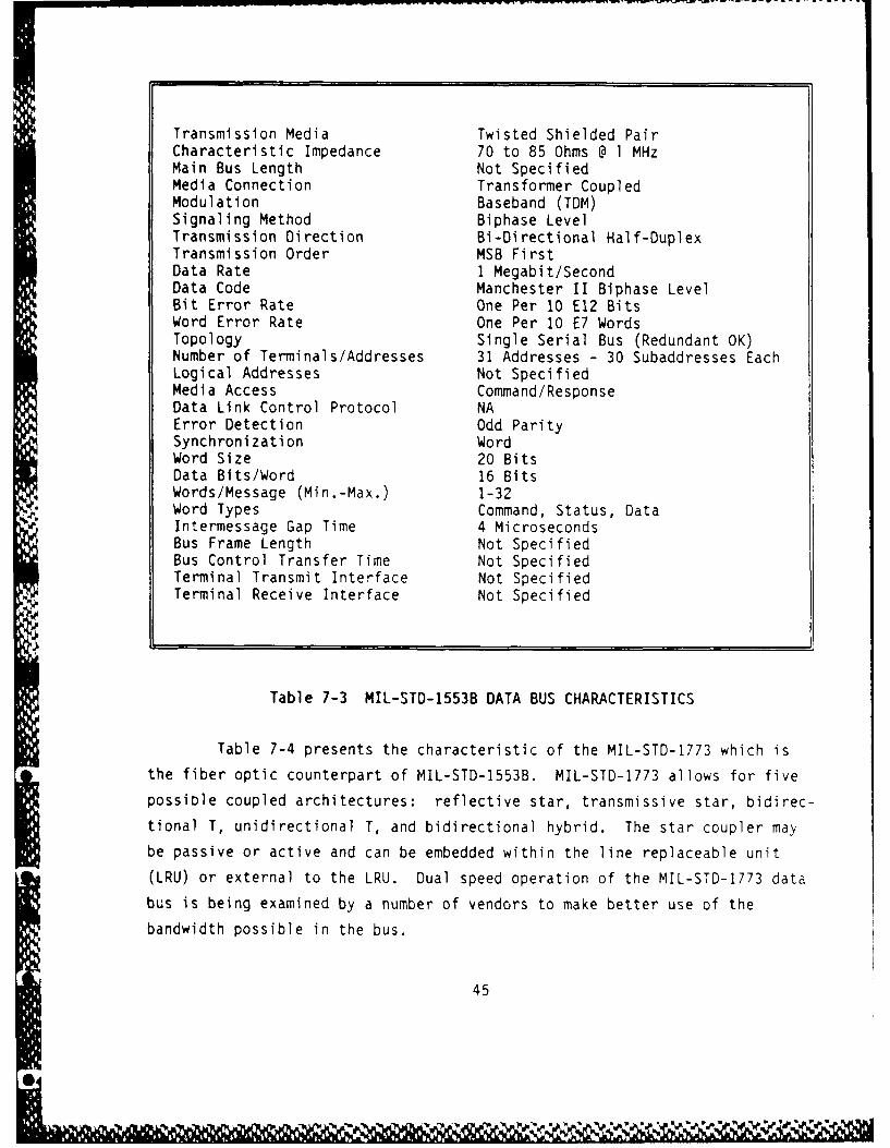
Transmission Media Twisted Shielded PairCharacteristic Impedance 70 to 85 Ohms @ 1 MHzMain Bus Length Not SpecifiedMedia Connection Transformer CoupledModulation Baseband (TDM)Signaling Method Biphase LevelTransmission Direction Bi-Directional Half-DuplexTransmission Order MSB FirstData Rate 1 Megabit/SecondData Code Manchester II Biphase LevelBit Error Rate One Per 10 E12 BitsWord Error Rate One Per 10 E7 WordsTopology Single Serial Bus (Redundant OK)Number of Terminals/Addresses 31 Addresses - 30 Subaddresses EachLogical Addresses Not SpecifiedMedia Access Command/ResponseData Link Control Protocol NAError Detection Odd ParitySynchronization WordWord Size 20 BitsData Bits/Word 16 BitsWords/Message (Min.-Max.) 1-32Word Types Command, Status, DataIntermessage Gap Time 4 MicrosecondsBus Frame Length Not SpecifiedBus Control Transfer Time Not SpecifiedTerminal Transmit Interface Not SpecifiedTerminal Receive Interface Not Specified
Table 7-3 MIL-STD-1553B DATA BUS CHARACTERISTICS
Table 7-4 presents the characteristic of the MIL-STD-1773 which is
the fiber optic counterpart of MIL-STD-1553B. MIL-STD-1773 allows for five
possible coupled architectures: reflective star, transmissive star, bidirec-
tional T, unidirectional T, and bidirectional hybrid. The star coupler may
be passive or active and can be embedded within the line replaceable unit
(LRU) or external to the LRU. Dual speed operation of the MIL-STD-1773 data
bus is being examined by a number of vendors to make better use of the
bandwidth possible in the bus.
45
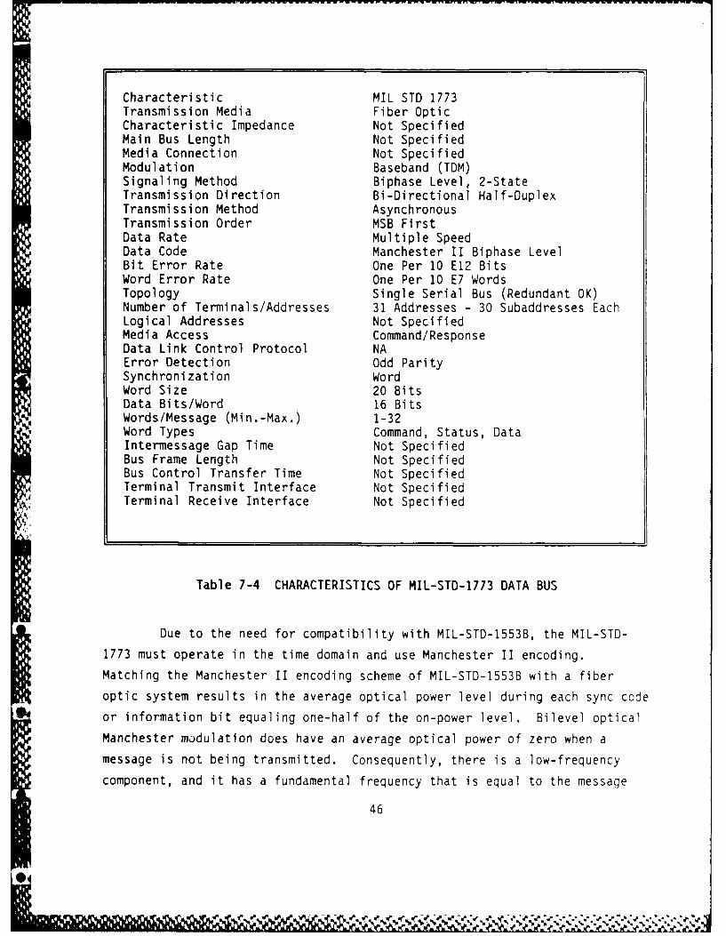
Characteristic MIL STD 1773Transmission Media Fiber OpticCharacteristic Impedance Not SpecifiedMain Bus Length Not SpecifiedMedia Connection Not SpecifiedModulation Baseband (TDM)Signaling Method Biphase Level, 2-StateTransmission Direction Bi-Directional Half-DuplexTransmission Method AsynchronousTransmission Order MSB FirstData Rate Multiple SpeedData Code Manchester II Biphase LevelBit Error Rate One Per 10 E12 BitsWord Error Rate One Per 10 E7 WordsTopology Single Serial Bus (Redundant OK)Number of Terminals/Addresses 31 Addresses - 30 Subaddresses EachLogical Addresses Not SpecifiedMedia Access Command/ResponseData Link Control Protocol NAError Detection Odd ParitySynchronization WordWord Size 20 BitsData Bits/Word 16 BitsWords/Message (Min.-Max.) 1-32Word Types Command, Status, DataIntermessage Gap Time Not SpecifiedBus Frame Length Not SpecifiedBus Control Transfer Time Not SpecifiedTerminal Transmit Interface Not SpecifiedTerminal Receive Interface Not Specified
Table 7-4 CHARACTERISTICS OF MIL-STD-1773 DATA BUS
Due to the need for compatibility with MIL-STD-1553B, the MIL-STD-
1773 must operate in the time domain and use Manchester II encoding.
Matching the Manchester II encoding scheme of MIL-STD-1553B with a fiber
optic system results in the average optical power level during each sync code
or information bit equaling one-half of the on-power level. Bilevel optical
Manchester modulation does have an average optical power of zero when a
message is not being transmitted. Consequently, there is a low-frequency
component, and it has a fundamental frequency that is equal to the message
46

- ~ ~ ~ ~ ~ ~ ~ W we Now~, a' ------ w J S . -
rate, often 10 Hz or less. Fiber optic receivers are usually ac-coupled to
compensate for the photodetector's electrical signal levels, which are not
very large in comparison with the magnitudes of amplified drift and offset
voltages. Because of this, special signal processing is needed to offset the
effect of the low-frequency component.
Several techniques have been developed for dealing with this low
frequency component, but these are susceptible to noise from within the
system. The result is the transmitter sections must be much better decoupled
from sources of noise in their equipment and must be much quieter when they
are not transmitting. In addition, because of the low input power levels to
the fiber-optic receivers, the front-end electrical signal levels are much
lower in MIL-STD-1773 receivers than in those for MIL-STD-1553B. To obtain
satisfactory performance with the greatly reduced signal level, careful
shielding is required, as well as decoupling of electrical interference on
subsystem lines entering the receiver.
Since optical signals cannot assume negative values, the receiver
' outputs, which are complementary and thus never low at the same time, cannot
be used to identify the no-message state in a MIL-STD-1773 system. As a
result, the no-message state and the off state of a two-level Manchester II
biphase bit cannot be distinguished. In MIL-STD-1773, it is considered good
practice to design fiber-optic receivers with three output states, even
though the receivers have only two input states. This is done for com-
patibility with the outputs of wire-based receivers.
Table 7-5 presents the characteristics of the ARINC 429 data bus.
04
I. S47
V W N

Transmission Media Twisted Shielded PairCharacteristic Impedance 75 + 5 OhmsMain Bus Length Not SpecifiedMedia Connection Direct CoupledModulation Baseband (TDM)Signaling Method RZ BipolarTransmission Direction Uni-DirectionalTransmission Method Asynchronous BroadcastTransmission Order LSB FirstData Rate 12-14.5 KHz or 100 KHzData Code RZ BipolarBit Error Rate Not SpecifiedWord Error Rate Not SpecifiedTopology Serial BusNumber of Terminals/Addresses Less Than 20Logical Addresses Not SpecifiedMedia Access Point to PointData Link Control Protocol NAError Detection Odd ParitySynchronization WordWord Size 32 BitsData Bits/Word 19 BitsWords/Message (Min.-Max.) IWord Types Not SpecifiedIntermessage Gap Time 4 Bit TimesBus Frame Length Not SpecifiedBus Control Transfer Time NATerminal Transmit Interface Not SpecifiedTerminal Receive Interface Less Than 20
Table 7-5 ARINC 429 DATA BUS CHARACTERISTICS
48
S
Z N

Table 7-6 presents the characteristics of the General Aviation
Manufacturers' Association (GAMA) Avionics Standard Communication Bus (ASCB).
Transmission Media Twisted Shielded Pair
Characteristic Impedance 125 OhmsMain Bus Length 125 FeetMedia Connection Transformer CoupledModulation Baseband (TDM)Signaling Method Biphase LevelTransmission Direction Bi-Directional Half-DuplexTansmission Method AsynchronousTransmission Order LSB FirstData Rate 2/3 MHz + 0.05%Data Code Manchester II Biphase LevelBit Error Rate One Per 10 E8 BitsWord Error Rate Not SpecifiedTopology Dual Serial BusNumber of Terminals/Addresses 48Logical Addresses Not SpecifiedMedia Access Not SpecifiedData Link Control Protocol HDLC (BOP)Error Detection Cyclic Redundanc) CheckSynchronization FrameWord Size 2 BytesData Bits/Word 16 BitsWords/Message (Min.-Max.) 1-256Word Types Not SpecifiedIntermessage Gap Time 8 Bit Times (Min.)Bus Frame Length 25 msBus Control Transfer Time 50 msTerminal Transmit Interface One Bus OnlyTerminal Receive Interface Both Buses
Table 7-6 ASCB DATA BUS CHARACTERISTICS
.4
% M7

Table 7-7 lists the characteristics of the Collins Serial Digital Bus
(CSDB).
Transmission Media RS-422A Twisted Shielded Pair
Characteristic Impedance Not Specified
Main Bus Length Not SpecifiedMedia Connection Not SpecifiedModulation Not SpecifiedSignaling Method NRZTransmission Direction Bi-Directional Half-DuplexTransmission Method AsynchronousTransmission Order LSB FirstData Rate 12.5 KBits/Sec or 50 KBits/SecData Code Not SpecifiedBit Error Rate Not SpecifiedWord Error Rate Not SpecifiedTopology Not SpecifiedNumber of Terminals/Addresses Not SpecifiedLogical Addresses Not SpecifiedMedia Access Not SpecifiedData Link Control Protocol Not SpecifiedError Detection Not SpecifiedSynchronization Not SpecifiedWord Size Not SpecifiedData Bits/Word 8 BitsWords/Message (Min.-Max.) Not SpecifiedWord Types Not SpecifiedIntermessage Gap Time Not SpecifiedBus Frame Length 50 msBus Control Transfer Time Not SpecifiedTerminal Transmit Interface Not SpecifiedTerminal Receive Interface Not Specified
Table 7-7 COLLINS SERIAL DIGITAL BUS CHARACTERISTICS
50
%~ % 1.% _~~"% Zta V

Table 7-8 presents characteristics of the Boeing DATAC bus. This bus
uses carrier sense multiple access with collision avoidance. It provides a
complete communication channel from the transmitting system's memory to the
receiving systems' memory. Once a terminal has transmitted, it must satisfy
three requirements before it can transmit again:
(1) a frame time, common to all terminals on the bus, must have
elapsed
(2) a sync gap, common for all terminals, must have existed on
the bus
(3) a terminal gap, common for all terminals, must also have
existed on the bus.
The receiver of the terminal transmitting monitors the transmission
and checks that each label transmitted has been authorized, contains the
correct channel information, and the number of words allowed in that stringhas not been exceeded, and the number of wordstrings in a message has not
been exceeded. Any fault causes the transmitter to be inhibited for the
remainder of that message. It is allowed to try again on the next frame
time. This continues until a certain number of successive tries are
unsuccessful, at which time the terminal is permanently disabled. It is not
clear how a receiver monitoring fault is handled based on information
available at this time.
51

Transmission Media Twisted Pair (Non-Shielded, Insulated)Characteristic Impedance Not SpecifiedMain Bus Length 93 MetersMedia Connection Transformer Coupled (Current Mode)Modulation Baseband (TDM)Signaling Method Biphase LevelTransmission Direction Bi-Directional Half-DuplexTransmission Method Asynchronous BroadcastTransmission Order LSB FirstData Rate 1 Megabit/SecondData Code Manchester II Biphase LevelBit Error Rate One Per 10 E12 BitsWord Error Rate Not SpecifiedTopology Single Serial Bus (Redundant OK)Number of Terminals/Addresses 128 PhysicalLogical Addresses Not SpecifiedMedia Access ContentionData Link Control Protocol CSMA/Collision AvoidanceError Detection Odd ParitySynchronization FrameWord Size 32 BitsData Bits/Word 16 BitsWords/Message (Min.-Max.) 1-4096 (256 Words/String, 32 Str/Msg)Word Types Not SpecifiedIntermessage Gap Time 14 Bit Time Min. (Terminal Dependent)Bus Frame Length 50 msBus Control Transfer Time Not SpecifiedTerminal Transmit Interface Not SpecifiedTerminal Receive Interface Not Specified
Table 7-8 BOEING DATAC BUS CHARACTERISTICS
52
'N

Table 7-9 presents the characteristics of the SAE AE-9B Linear Token
Bus.
Transmission Media Fiber Optic or ElectricalCharacteristic Impedance 50 ohms electricalMain Bus Length 300 m required, 1000 m desiredMedia Connection Optical or Transformer CouplingModulation NRZSignaling Metlod Biphase LevelTransmission Direction Bi-Directional Half-DuplexTransmission Method Asynchronous Broadcast or MulticastTransmission Order LSB FirstData Rate 25, 50, or 100 MBPS (Preset)Data Code ManchesterBit Error Rate One Per 10 E12 BitsWord Error Rate < I Every 4 Hours at BIR*Topology 1 to 4 Serial Linear BusesNumber of Terminals/Addresses 128 Physical - 512 Subaddresses EachLogical Addresses 2 E15Media Access Token PassData Link Control Protocol Token or Message FrameError Detection CCITT-CRC-16Synchronization FrameWord Size 16 BitsData Bits/Word 16 BitsWords/Message (Min.-Max.) 1-256 Required, 4K DesiredWord Types Not SpecifiedIntermessage Gap Time 10 Bit TimesBus Frame Length Not SpecifiedBus Control Transfer Time Not SpecifiedTerminal Transmit Interface 4 BusesTerminal Receive Interface 4 Buses
*BIR : Benchmark Information Rate
Table 7-9 SAE LINEAR TOKEN BUS CHARACTERISTICS
S., 53
or

The AE-9B proposed token passing linear bus protocol involves four
simple states:
a) Bus Initialization
b) Normal Token Passing
c) Station Insertion
d) Station Management.
The token is passed from lowest physical address to highest physical
address and then back to the lowest.
The worst case delay in the AE-9B linear bus is directly dependent on
the maximum allowable message length. Message latency can be easily handled
by implementation of system level message priorities.
Table 7-10 gives characteristics of the SAE High Speed Ring Bus
(HSRB).
0. 5
@44

Transmission Media 50 Mbps Coax, 100 Mbps Fiber OpticCharacteristic Impedance 75 ohm TriaxMain Bus Length 2 km Ring LengthMedia Connection Optical or Transformer CouplingModulation NRZISignaling Method Biphase LevelTransmission Direction Uni-DirectionalTransmission Method Asynchronous BroadcastTransmission Order LSB FirstData Rate 10-1000 MBPSData CodeBit Error Rate One Per 10 E12 BitsWord Error Rate Not SpecifiedTopology Ring - 2 to 128 StationsNumber of Terminals/Addresses 128 Physical - 512 Subaddresses EachLogical Addresses 2 E15 - Broadcast and MulticastMedia Access Token PassData Link Control Protocol Token or Message FrameError Detection CCITT-CRC-16Synchronization FrameWord Size 16 BitsData Bits/Word 16 BitsWords/Message (Min.-Max.) 1-4096Word Types Not SpecifiedIntermessage Gap Time Not SpecifiedBus Frame Length 80K BitsBus Control Transfer Time 10 Million Data BitsTerminal Transmit Interface 4 BusesTerminal Receive Interface 4 Buses
Table 7-10 SAE HIGH SPEED RING BUS CHARACTERISTICS
The ring bus offers superior throughput capability when compared with
the linear bus due to short point-to-point media links between nodes. In the
area of fault recovery and reliability, the ring is less attractive due to
the need for failed node bypassing using either mechanical relays or fiberoptic switches. Ring reconfiguration may take up to 25 msec when bypasses
are activated. In addition, a limit must be placed on the number of
consecutive nodes which may be bypassed, due to a lower power budget in the
55

short point-to-point links and the relatively high losses inherent in the
bypass devices (both wire and fiber optic).
0
* 56
0M

8.0 BUS PERFORMANCE CHARACTERISTICS
The performance characteristics of a bus, in a given architecture,
are affected primarily by Data Latency and System Delays.
Data Latency
Data latency is the delay from the time when a piece of information
becomes available at a source terminal to the time it is received at the
destination. The degree of latency is affected mainly by the architecture
and the protocol of the message transmission. Hierarchical architectures, as
previously defined in Figure 5-1, are inherently subject to longer delays
than are parallel architectures, due to the number of nodes (common exchange
points) through which a message must pass. When an hierarchical interface is
used, and time sensitive information is transmitted between levels of the
hierarchy, time tagging of the data messages may be necessary. The time tag
(if implemented) would become part of the message and would be used at the
destination to determine the "freshness" and/or urgency of the message/data.
In the case of an hierarchical architecture, such as that in Figure 5-1, node
information is made available at different times at various levels of the
architecture, dependent on the number of nodes through which it must pass.
For example, if the flight control computers control the initial transfer of
the node data/status, and depending upon the protocol, the node data/status
information can then be made available to mission oriented computers and/or
other FCC's with minimum delay. The next level transfer is controlled by the
mission oriented computers, and again depending upon the protocol, the
data/information will eventually (after incurring routine delays) arrive at
the destination terminal/computer, and eventually the end destination (in
this example, the video display or graphics generator computer). During this
same period, the applications computer (avionics, navigation, etc.) can be
providing information to other computers, within the hierarchical
architecture, based upon the node data/status information it currently has
available. If however, the node data/status information had been changed
during an activity controlled by the other applications computers, there is a
potential for error introduction due to one or more of the flight control
computers being in a node status different than the other avionics or flight
57
0% NNNN-
-- ~~ - w- WW IF Wv-wnu -W -P - -.. i rv - rri ;r--w . _. -_ -
control computer currently performing the activity. In order to minimize the
potential for error due to latency, the node data/status message could
include a time tag generated when it is/was sent frum the node select
computer. When each successively higher level within the architectural
hierarchy generates a message/command, it would automatically pass along the
time tag of the node data/status message. When the message arrived at the
various destinations, within the hierarchy, a comparison would be made of the
current and new node data/status values and the time tag to ascertain the
validity of the command. In general, the actual latency of a message within
a given architecture is determined by the rate at which the bus structure(either autonomously or centrally controlled) allows a "sending" terminal the
opportunity to "latch-on" to the bus in order to transmit its message/data.
For a centrally controlled bus, to obtain the least possible (i.e., minimum)
N latency, the bus controlled would be configured to (a) continually poll the
terminals within the bus structure, (b) sense (respond to) the service* request bit in the terminal status word, and (c) initiate the terminal-to-
terminal (or terminal-controller) message transfer.
With an increase in the distribution of processing tasks to more
specialized computers and away from a central general purpose computer
concept, an event based scheduling scheme may become a good alternative for
some applications. When task scheduling is based upon events rather than
time, the latency of a message becomes more critical and the continuous
polling technique is an effective way to reduce the message latency. For an
illustration of the event based scheduling, refer to the local display bus of
Figure 8-1. The display computer is normally operating in response to-? messages from the mission computer, and its BCIU which controls the local
display bus is continuously polling for keypad entry. When the keypad ispressed a message is sent back to the display computer, signaling an event towhich the display computer must respond. The display computer will break out
of its normal cycle, process the keypad message, and upon completion of this
processing will have available keypad information that can be sent to other
devices on the mission computer bus.
In this application two advantages are obtained from the event based
scheduling and continuous polling. The latency of the message as it passesfrom a local bus to a higher level bus is minimized, and component faults in
58
%,
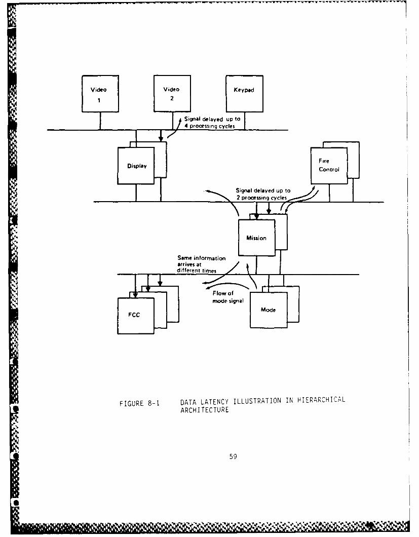
Video Video Keypad
1 2
Signal delayed up to
I)4 processing cycles
F ireDisplayCotl
Mission
Same informationarrives atdifferent timnes
Flow ofmode signal
ModeFCC
FIGURE 8-1 DATA LATENCY ILLUSTRATION IN HIERARCHICALARCHITECTURE
59

the communication system are identified early to provide time for management
of the failure. For example, a simple management scheme would be to
retransmit if the status response were not returned with the message error
bits clear. On the negative side, the checkout is more difficult due to the
inability to repeat a particular condition. When all scheduling is time
based, then a repeatable test scenario can be generated and system response
evaluated deterministically. When operation is based on asynchronous events,
only a statistical comparison of results from multiple tests is valid.
On a single hierarchical level there are several protocols than can
be used within the bus architecture framework, and this protocol choice
affects message latency. The use of a stationary master that polls all
terminals on a regular basis provides minimum latency for a small number of
terminals on the bus. A second approach where bus control is exchanged among
a limited set of master computers introduces potentially greater latency,
depending upon the message table orientation of each master computer. If bus
control capability exists in every terminal that may have a time critical
message, the message latency will be in the range of several (2-4)
• ~ milliseconds. If continuous polling is done between every message
transmission, latency improves; however, a large bandwidth penalty is paid.
Continuous polling can only be used on buses with low activity levels.
System Delays
Average transfer delay is defined as the sum of delays resulting from
queueing delay, access delay, and transport delay.
Queueing Delay. Queueing delay is characterized by message arrivals
and arrival rate and represented (characterized) as a Poisson Distribution.
The mean queueing delay consists of the average delay incurred due to a
message waiting for a previous message within the BIU to be serviced. The
BIU's are effectively a single server queue, and therefore the queueing dela,
is a delay imposed on the user due to the BIU transmit buffer being full.
This delay neglects the user/BIU interface message processing rate
limitations and is dependent only on the message interarrival time as
determined from the offered load.
Access Delay. In the case of the CSMA/CP protocol, the mean access
delay is determined by considering the two inherent access modes. The delay
due to the random mode and the delay due to the ordered access mode are
K60
0.
factored with the probabilities of being in their respective states and
combined to equal the mean access delay.
For the random access delay there are two components of delay:
1) delay due to the bus being busy, and 2) delay due to a collision. For the
bus to appear busy, at least one other message must arrive before the message
that encounters the media active state. Therefore, the probability of the
bus being busy is the probability of two or more arrivals within the same
time window.
The probability of a collision can be described by the probability of
two arrivals in time and the probability of three or more arrivals in time.
The delay due to a collision is determined by the time required to recognize
a contention, issue the jamming signal (approximately 1 microsecond), wait
for the appropriate gap time, and then the wait until the appropriate time
slot. Because the load distribution is assumed to be equal among the networkI BIUs, the average delay for the time slot count to reach the assigned time isone-half the total scan time for the time slot sequence as determined by the
loading conditions.
Looking at the access delay encountered by a message arrival during
the ordered access mode, two conditions are possible: 1) message ready
before the time slot arrives, or 2) message ready after the appropriate time
slot has passed. For an equal load distribution, the probability of each
case is 0.5.Transport Delay. The transport service time is determined by the
transmission rate, the message length, and the overhead required for each
transmitted packet. The overhead includes the following:* Tga between messages
" Turn on time (power strobed BIUs)
" Packet encapsulation
* Propagation delay of 50 meters
* Acknowledge turn on plus
" Propagation delay
* Acknowledge message
System level fault management is further facilitated by the
monitoring of network statistics at each node. During operation, the BIUs
collect the following statistics:
61
V.WIAx -N6%Nk

* Number of collisions
• Number of collisions during own transmission
* Number of packet rejects due to decoder buffer full
* Number of successful transmissions
* Number of unsuccessful transmissions
• Number of data transmissions received
* Number of status responses received
* Number of commands received
62

9.0 FAILURE MODES AND EFFECTS (BUS ARCHITECTURES)
Operation of the current and next generation digital aircraft
requires the proper function of a number of interrelated/interconnected
systems/subsystems/components within the framework of an integrated bus
hierarchy/structure. Intermittent or erratic behavior or total failure of
one or more modules/components can impact the ability of the aircraft to
perform its intended function. In some cases, the impact will be transparent
as the fault/error/mistake is automatically detected, the failed
module/component identified and a redundant "like element" (similar or
dissimilar) activated or "switched-to" automatically. Continued successive
failures (or in the worst case, multiple simultaneous failures) could result
in increased pilot workload, loss of function, or in the most severe case,
the total loss of aircraft.
Because of the nature of the interactive relationships of
systems/subsystems in these aircraft, failed modules/components may affect
not only the subsystem in which they are embedded, but the failure's effects
may propagate into other subsystems. This failure propagation potential
between multiple systems/subsystems is greatly magnified by the differing
levels of "functional integration" where data and information are exchanged
between and among systems/subsystems (using bus architectures and structures)
as a requirement for normal operation.
Failures that could cause loss of essential mission capability or
loss of aircraft must be protected against by using equipment redundancy,
analytical redundancy, or "functional redundancy" to provide for continued
operation after one or more failures. The redundancy may be applied at the
system level (multiple buses or flight control computers), at the sensor
level (redundant INS, AHRS, DADC, etc.), or at the module/component level
(multiple similar or dissimilar microprocessors located in multiple processor
subsystems). Failures that result only in some loss of function, restricted
operation, or increased pilot workload, may or may not require redundancy,
depending on the exact nature of the loss and the probability that such a
loss will impact aircraft performance capability (i.e., navigation or
position location) or aircraft flight safety (i.e., CAT II or CAT III
landing). Failures that reduce the level of hardwiare redundancy or
63
NN

analytical redundancy, without loss of functional capability, may be able to
be tolerated without performance degradation.
Failures can also result from external disturbances or internal
malfunction and can be either transient or permanent. Transient faults can
often be ignored if the system is designed to tolerate such faults. In other
cases, a transient fault can cause a more serious failure, such as the
interruption of an instruction sequence in a computer, which in turn could
cause a time-out or retry sequence, resulting in the completion of the
computation using "stale" data. Permanent failures, on the other hand, must
be recognized as such, and action taken to reconfigure around the failure.
Environmental effects can often be the cause of the failure. In the
case of wire buses, heat, power supply surges (spikes), or low voltage levels
could cause permanent or intermittent operation of an electronics unit or
* . corruption of the bus data, which in turn would cause incorrect data and/or
information to be passed to another unit in the hierarchy. Loss of
* electrical integrity (due to faulty shielding, grounding, or loss of cable
integrity) could result in susceptibility to electromagnetic radiation, thus
causing erroneous or erratic behavior.
In general, failures may exist in any one of the five functional
elements relating to the integration of two or more subsystems. These
functional elements include:
-<(a) computers which process the data that are exchanged between
subsystems;
(b the data bus interfaces;
(c) the data bus(es) themselves;
*(d) the input/output devices that govern the transmit/receive
functions; and
*(e) the system errors.
Table 9-1 summarizes the potential faults which can cause
intermittent or erratic behavior or even total failure of the networked
architecture to communicate data and information to the various
systems/subsystems within the structure.
64
0%

tn 00m.
V) o E
-5 s
C3 CC 04
0 W .'4m0CD u a
Z in Eu 0 .
C- V) E .0 4.! U- > C3
"M4-00 C -a to-
- n 1- 4
0.. 0 0 0 0 o.0~~ U1- .-
4)C.) 0 .
0n C. U m C 0 mn*~I 6n w ) ) 4 ~ E n ~ 42i CL Eu C Eu 0. - r E 4cm - 4)
aZ v IN)~- i 0 s3 -.
0n 0 u- -o .1 D 4aa4 2 - - I-
0. 0 -0m 0
U? 0 n
00
- Q C . CU 400 0 0 C0- 0
0 0m 0 0 04 4) 4 0 )44 ~ ~ ~ ~ ~ ~ : CL C - 4 . -4) , 4 .
4/ o C 4 4) co m.- - 4 - 4 4 ) .Eu~~~~~C (n) 4 -- - . - - - 4. -4 44- C ~ . .0 E . u 4. 4 u 4 4 40 4- ~~~ ~ ~~4 0 - 4 - 4. 3 - 4 0 - 4 )
444~~~~t -. U. 0- U ' ' - 0- - l '- l 4~. 4)4 .4 -l 044 . 4
S 0. - a V uu -KA~ c 04 a4 -4) E nEn- ** -C E.uCL s
-~~~ ~ .4 - 4 - -CV00 0 In 1 04 0 00 40
0 -m 04 0404
'D CC
0uC
CL 4 L.4 5 4 Eu 0m4 CL 13 x -
- 0 Eu 44 4.4 En00.
.4 C4 4.. C)44 4-
The following consideratior1s must be made concerning the possible failures of digital data buses: (1) transmission failures that may occur; (2) the effect on subsystems that are connected to the data bus by a bus controller or remote terminal failure: and (3) the effect of multiplex hardware failure. The navigation system must be self-contained and the aircraft must not become "lost" because of any type of transient. These safety requirements lead to subsystem requirements to store critical data in multiple locations and to recover rapidly from failures and upsets.
The three failure modes are: (1) no transmission; (2) incorrect transmission; and (3) failure to relinquish control. A fault with these failure modes and some of the related causes is shown in Figure 9-1. These failure modes are discussed in further detail in this paper •
. Transmission Error
If the multiplex terminal hardware detects either an invalid word or a transmission discontinuity, the word and message are to be considered inv~lid. This m~ssage invalidation requirement may cause some systems (i.e., electrical multiplex (EMUX)) a problem. Since the EMUX systems usually have bit-oriented data rather than word or multiple words (message) oriented data, errors in a word following the reception of good data will inval !date good data. Message completion failures should always be detected in a mtlltiplex system and are detected by the bus controller by either the suppression of the status word or the setting of th~ message error flag in the status word. The message error flag removes ambiguity ~s to whether the error occurred before the message was validated by the remote terminal or in the response to the message. Data transmission errors ar~ handled by special error-handling interrupt software. The software will indicate whether (1) the command is to be retried, (2) the bus is to be used for the retry, ~nd (3) whcthe1· the tr~nsmttted data (1f any) should be 1nva11dated. Tables 9-2 and 9-3 show the error identificatfon types and the e9rresponding failure classes and error correction techniques.
66

CU
V)-
>. 0 V) I-
A-C
.- ') CS00.)
CZ.- w.
QLA-
C.CL
C LLJ
u V)
Ln u
VC.
ev /C.-
LC CE
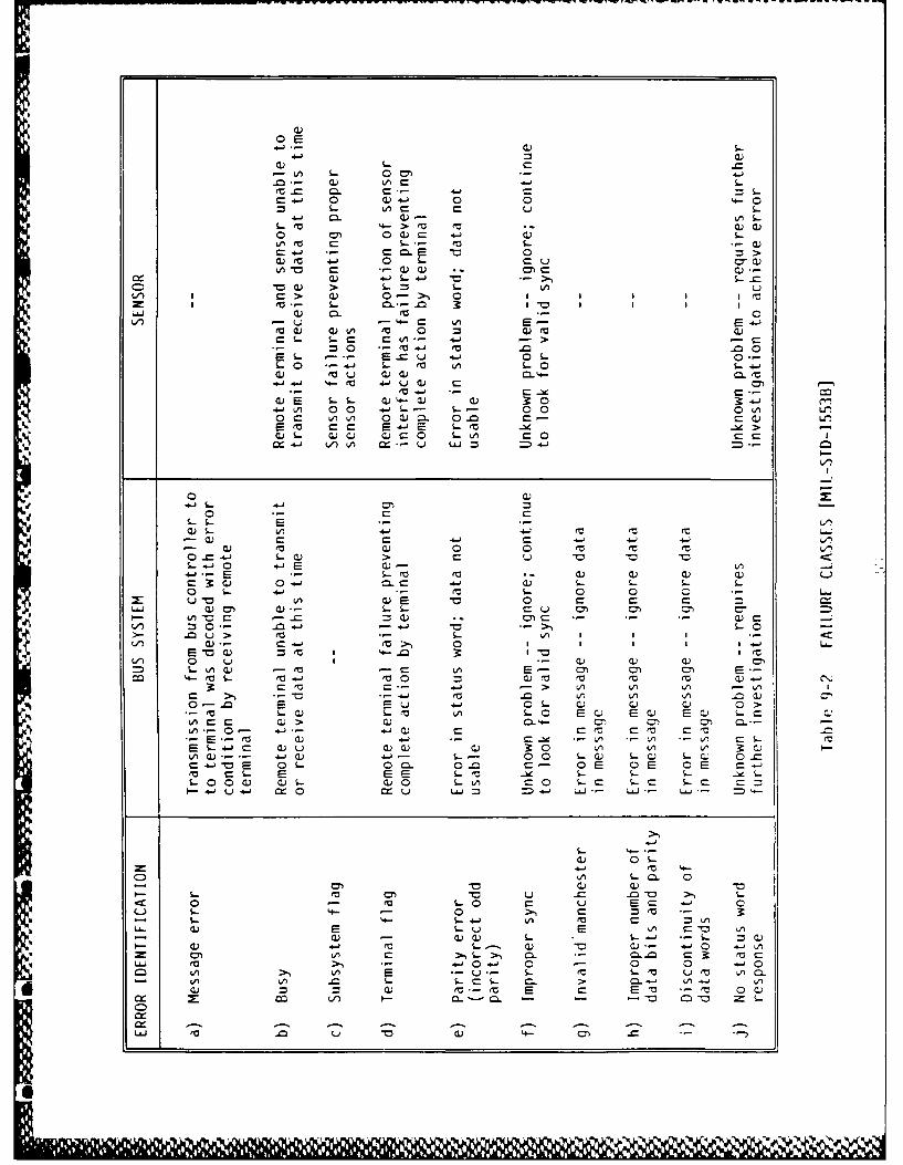
0 L)
C L C Z
a.- 0 a)- 0 0
c o.E -t: 0
W= W-L- uvi aO > ~ L
I~~~ C CL 0- ~ 0ILJJ 0)0U
S- o ~ , e 0 S.. 0' 4-
4-1 LC Ccc u ~ -> -C
EL - ECU4- a 0- 3L 0-1 VW- L VU o W. - . 0 0 ( L
o n 1) 0 ) - 0 C. C- a
E' ac E -E S.L' 1 _l ~>-WL- WWl WCOC L'..O )
r_ C C14-
c- Wa) 0 0 ev (V 'LW1 > C 0
L4-0 4-E CE' s - 0) ecc ) Wu w
CDW 04- C.c 4-) 1.-L L L6 L0 L- +j 0 0 0
W~ c E 0 c C: cLL- 0" V)_ICU 0'_
...- u L> m
C)c..-a ' >% 0 I III..
0~ uV'-.
-C 0 V E-1
Cu I, *n 'V =0 Q CSWO-. EU- C-' QL0) C.) 0 >
LCU L'V L E C E a EW LC)LA C W)> a) CL 4-- 0) =1 ..Ln 0 4-' 4-1W C- C(V Ca fu c r
0)- 4-Jr C.1 *- ) *- n/ LA CEL.- C WU) c)0 W)u 30 LA V) C)
Lna).--- 4 ) .-- L- 00 Lw LW LW cC4-'aE oL 00 00 C- E 0 E OE C.ea CL E E E S- L le
4-j'rCD L
V)Voo EO 0
0 4- 'VL0 C Ue Cvb - L'4- L.-J ( C
c >W -- 00 L C..~ -M c9-. Wa 4-1 0 W 0) 00.-
LA UA C S-,>- 0.. 0.0 C3 (VCvi cA. SV> 4 .- 0- > 0M 0 LA -0
ea>, A E- L V L 'a U m I0 w- AICo CL 0 V).- IA-M4 0 W'V-"V 5 EV *rC00
Z -oco - - o: ~0L ac
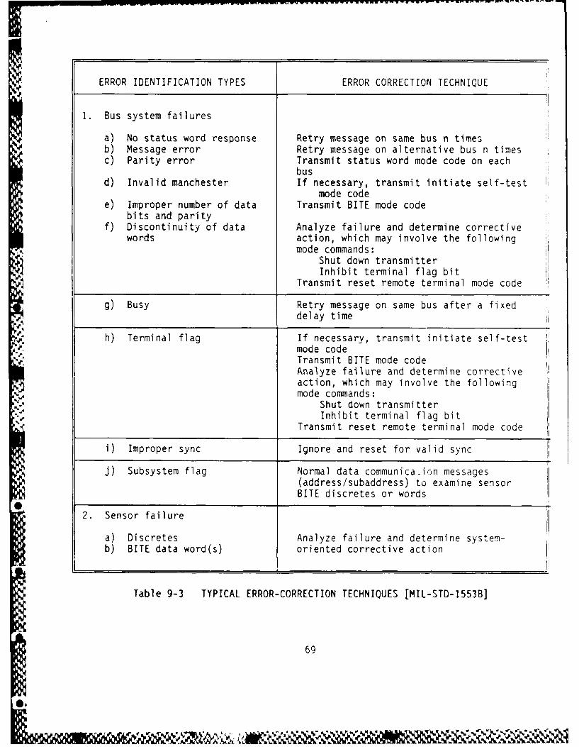
ERROR IDENTIFICATION TYPES ERROR CORRECTION TECHNIQUE
1. Bus system failures
a) No status word response Retry message on same bus n timesb) Message error Retry message on alternative bus n timesc) Parity error Transmit status word mode code on each
busd) Invalid manchester If necessary, transmit initiate self-test
mode codee) Improper number of data Transmit BITE mode code
bits and parityf) Discontinuity of data Analyze failure and determine corrective
words action, which may involve the followingmode commands:
Shut down transmitterInhibit terminal flag bit
Transmit reset remote terminal mode code
g) Busy Retry message on same bus after a fixeddelay time
h) Terminal flag If necessary, transmit initiate self-testmode codeTransmit BITE mode codeAnalyze failure and determine correctiveaction, which may involve the followingmode commands:
Shut down transmitterInhibit terminal flag bit
Transmit reset remote terminal mode code
i) Improper sync Ignore and reset for valid sync
j) Subsystem flag Normal data communica-ion messages(address/subaddress) to examine sensorBITE discretes or words0
2. Sensor failure
a) Discretes Analyze failure and determine system-b) BITE data word(s) oriented corrective action
Table 9-3 TYPICAL ERROR-CORRECTION TECHNIQUES [MIL-STD-1553B]
69

No Transmission
The user should listen to the bus it transmits on for its request
address. If no bus controller activity is detected, the user should transfer
listening to the other bus for its request address. If no activity is
detected on the other bus, the user should continue toggling between the
buses in search of bus controller activity.
Incorrect Transmission
The most serious failure for the bus controller is erroneous
transmission. An independent frequency source should be used by the bus
controller to provide monitoring and detection of transmission frequency
faults. The two common types of transmissions are broadcast (which is sent
on all of the channels) and command response (which is sent to a specific
address). An error in a broadcast transmission has the potential for system
failure if it is incorrectly validated at each of the addresses. An error in
a command response has a more limited effect since it only involves one
address. Each receiver should incorporate isolation provisions to ensure
that the occurrence of any reasonably probable internal line replaceable unit
(LRU) or bus receiver failure does not cause any input bus to operate outside
of its specification limits (both undervoltage or overvoltage).
Failure to Relinquish Control
Subsystem or terminal failures may be detected using built-in test
(BIT) circuitry. These failures are reported by the setting of the subsystem
flag bit or the terminal flag bit in the status word. In aircraft, dual-
redundant buses are used, so a terminal failure may be isolated to one bus.
Depending on the capability of the remote terminal hardware, the transmit BIT
word mode code can be a powerful diagnostic aid. For each fault, the action
to be taken must be determined, designed for, and implemented by the system.
Subsystem or terminal failures can also be detected without the use
of the optional terminal or subsystem flags. Bad data or non-varying data
from a subsystem may be interpreted as a subsystem failure. Repeated message
completion failures to a remote terminal via all possible data paths could be
considered as a loss of the terminal functions. The system software should
be used to detect these failures.
Bus controller operation in the event of failure is important to an
integrated data bus system. The primary bus controller should relinquish busAo.
70
-m _ M

control whenever it suffers a power interruption of a power supply which
might cause erroneous outputs. The primary bus controller should detect its
own bus control processing faults and remove itself as controller in a fail-
passive manner. Similarly, the backup bus controller should recognize
invalid control messages or the absence of valid control messages and revert
to active bus controller status. Monitoring techniques should provide
coverage for both hardware faults and software errors. Any undetected fault
in the primary bus controller which results in continuous erroneous
transmission will make all standby controllers ineffective. The bus
controller is structured such that two independent faults must occur in order
to cause erroneous transmissions.
Reliability for Flight Safety
Flight safety requirements allow no more than one unrecoverable9failure in the flight control subsystem per 10 flights. This failure rate
is consistent with AC-25-13091 and is appropriate for integrated systems.
The failure rate must encompass the entire flight control system including
the necessary supportive electrical power, hydraulics, and any other
subsystem used in the flight-critical capacity. When applied over the twoand three hour mission duration of the aircraft, a maximum failure rate of
- -6
3.3 x 10⁶ failures per flight hour (for a three hour mission) can be
.v. allowed.
Figure 9-2 gives an example for the determination of the loss of bus
control. The potential failures for the bus control example are given in
Table 9-4. The total failure rate must be equal to or less than the total
allowable defined above. In the example, the loss of bus control, DI, is
D, =(El +E 2 +E 3)(E 4 +E 5 +E 6 ) +E 7 +E 8 +E + E1 0 -5
By substituting in the values from Table 9-4, we obtain D 3.1012321 x 10
Therefore, in this example the data bus would fail to meet the reliability
requirements for flight safety.
71
%1 40
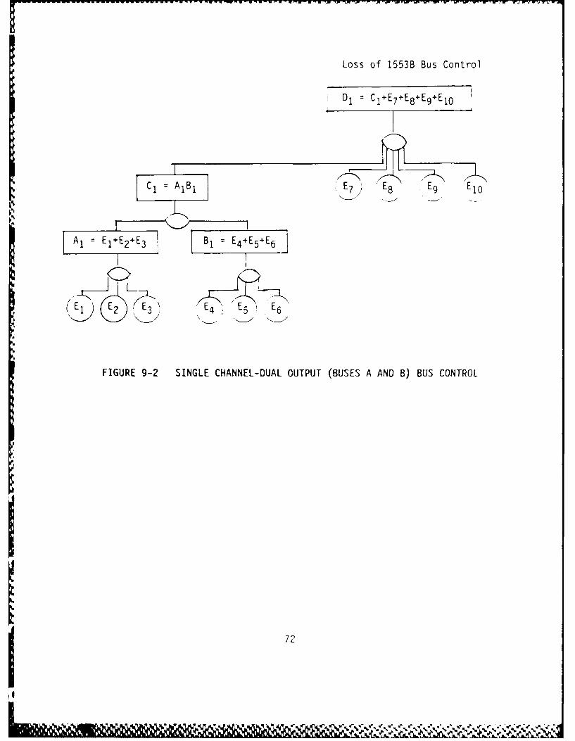
Loss of 1553B Bus Control
1 D, C1+E7+E8+E9+El0
Al El+ 2 E Bi E4+E5+E6
(E1 E2 E3 E, E5 'E
FIGURE 9-2 SINGLE CHANNEL-DUAL OUTPUT (BUSES A AND B) BUS CONTROL
1 72
4 ~ ~~ % % 5''~

ERROR ERROR SOURCE FAILURE RATE ( )
E* Bus A - Transformer Failure 10 6
E2 Bus A - Transceiver Failure 10 4
E3 Bus A - Decoder Failure 10-5
E4 Bus B - Transformer Failure 10-6
E5 Bus B - Transceiver Failure 10- 4
E6 Bus B - Decoder Failure 10-5
E Single Encoder Failure 10-5
E8 Internal Control Logic Failure 10-
E9 Interface Unit Failure 10
E Microprocessor System Failure 10-6
Table 9-4 POTENTIAL FAILURES RESULTING IN LOSS OF BUS CONTROLSINGLE CHANNEL - DUAL OUTPUT (BUSES A AND B)
I1 73

10.0 FIBER OPTIC DATA BUS FOR AVIONICS INTEGRATION
As stated in previous sections, the bus topology is the physical arrangement and interconnection of the various terminals. In a fiber optic bus, the elements utilized are: optical couplers: fiber cable: connectors: and splices. The design of these elements not only relates to system performance but also to system installation and maintenance. Because optical· power losses occur whenever any of these components or functions are inserted in the optical path, performance is affected. Table 10-1 presents the components and factors which influence the limits of optical bus technology as it applies to optical buses used for avionics integration. Optical Path
Basically, the optical path is the fiber optic cable. In designing the proposed avionics architecture, the fiber cable must be selected for minimal loss (across the bus) and wide bandwidth. In addition, the fiber cable must be constructed for strength and endurance during the life of the bus architecture; ease of installation; and long term environmental performance. Splices and Connectors
Interconnections between the fiber cable elrments (controllers, remote terminals, junctions, etc.) can be made with either splices or connectors. Splices in the fiber cable are easier to incorporate and provide lower losses than connectors; however, splices are permanent. Connectors, on the other hand can be mated/unmated hundreds of times with virtually no degradation in performance. Therefore, in the development (and design) of a fiber optic based avionics architecture optical couplers (connectors) should. be utili zed for bus interface connections to the physical _Q_us to minimize downtime due to repair and/or changes to the architecture structure or implementation induced by adding or deleting remote terminals or at the avionics boxes to the physical bus.
In the case of aircraft having pressurized bulkheads, several
penetrations through these bulkheads may need to be made. At these penetrations, the fiber optic cable can either be run "straight-through" the bulkhead or an optical connector (coupler) can be used on each side of the bulkhead. The tradeoff, in this case, is between the ease of installation
74

and rework using a connector (coupler) system or the lower loss and absenceof reflections using a spliced or through cable.
Table 10-2 deals with the concerns and issues associated with theimplementation of a high integrity fiber optic cable based avionicsarchi tecture.
175
-r o

COMPONENT FACTORS
o Couplers LossesNumber of Taps
o Fiber Fiber TypeModal NoiseConnectorsSplicingReflectionsCabling
o Optical Source PowerSpeed
o Optical Receiver Sensitivity-U Intermessage Dynamic Range
Intermessage Response TimeClock Recovery
- o Processing/Interface SpeedLogic Power Consumption
VHSIC/VLSI & GaAs
o Topologies PerformanceReliabilityFlexibilityInstallation and Maintenance
o All Cost
Table 10-1 OPTICAL BUS TECHNOLOGY LIMITS
O.
*% 0= 1

OPTICAL CULR
The two basic types of optical coupling techniques which are
considered for an optical data bus are star couplers and taps or tees.
A. In a transmissive star, N ports are designated as input ports, and NIA ports as output ports. The optical energy on any input port is split
more or less equally between all output ports, with a splitting lossof 10 log N. Star couplers also have an insertion loss and a port-port variation of 1-3 dB each depending on the number of ports.
r .f~.Stars in excess of 100 ports have been fabricated; however, forminimal cost and port-port variations, the practical limits ofcurrent technology is 64 ports.
B. Directional couplers for tapping a transmitter and receiver onto afiber optic bus are basically like a 4 port star transmissive starwith an excess loss of 0.5-1 dB. Typically a tap into the receivercan be accomplished with a 90/10 or 95/5 split providing 0.5-2.0 dBlink throughput loss, respectively, and a 10 dB to 13 dB tap-off orreduction of the link power into the bus receiver. For tapping thetransmitter into the bus, the throughput loss as well as the coupledtransmitter power reduction is 3 dB in commercially availablecouplers.
OPTICAL CABLES
Considerations involved in evaluating optical cables for a fiberoptic data bus include fiber design (including modal noise and reflection
F effects) and cable type and construction.
Size
Of the available fiber options, the 100/140 micron or the85 125 micron graded index fiber operating at 0.05 -m is optimum because:
-\(a) Their large core, high NA, and operation wavelength will support manymore modes, thus minimizing the modal noise limitation.
(b) Their large core enables greater LED coupled power, thus extendingthe application of LEDs.
(c) Their core-clad geometry makes it easier to make low excess loss starcouplers.
Table 10-2 CONCERNS AND ISSUESt~ecnnti rues)
7-

Reflections
Another consideration in the media analysis is reflections.Reflections result from an index of refraction discontinuity at connectors,poor splices, or mismatched fiber types. For example, with a star coupler,the main signal passes through the link; however, part of the signal is firstreflected at the star coupler dry connector (8%) and then again at thetransmitter dry connector (8%). The resulting reflected signal is down 22 dBwith respect to the main signal and delayed by 1 microsecond (1 nsec/meter).This reflected signal becomes a problem if it overlaps the next bustransmission and shows up as noise superimposed on this data. Therefore,
* consideration must be given to minimize reflections.
Connectors
Optical connectors which are suitable for use in a data bus are lowcost, easily installed, and typically low loss. The connector loss dependson the fiber size as well as the quality of the connector. For 100/140 mfiber, losses vary from 0.5 to 1.5 dB depending on connector quality.Available multi-way connectors have the advantage of simplifying a bulkheadpenetration and provide quicker connect/disconnect of a multi-fiber cable.Although there is no fundamental reason for higher loss in a multi-wayconnector, the losses in currently available connectors average approximately0.5-1 dB more than the loss in a single fiber connector.
Splicing
For field installation, maintenance, and repair the elastomericsplicing system has been identified as the best currently available splicingtechnique.
TECHNOLOGY - OPTICAL BUS TRANSMITTERS AND RECEIVERS
Fiber optic bus T/R design is driver by the goal of maximizing busp efficiency. This is necessary to fully utilize the benefits of the bus,
minimizing "dead" time, and allowing transfer of significant quantities ofdata.
An efficient bus transmitter and receiver are relatively easy to* design. However, providing ye-v quick transmitter power output stabilization
and very short receiver settling time at the start of a message significantly* increases the difficulty and complexity of the transmitter and receiver
design. A fast response clock recovery scheme is also critical to minimizing
Table 10-2 CONCERNS AND ISSUES(table continues)
78

the amount of time used for non-date. In summary, the more time used toperform overhead functions, the less time there is to transmit data, and theless the efficiency of the bus.
Maximizing Bus Efficiency
One of the principal considerations in maximizing bus efficiencyrevolves around the unique aspects of an optical transmission. Intensitymodulation of an optical carrier provides a unipolar transmission channel,unlike electrical current transmission over wire which may be bipolar.Unipolar signaling causes a DC shift between signal-on, and signal-offstates, which will disturb the operation of conventional receiver amplifiershaving AC coupling until the interstage coupling capacitances have had timeto accommodate the shift. A similar DC shift occurs between small and largesignals.
Thus to avoid a long settling time at the start of messages,receivers designed for data bus application either have a short AC couplingtime constant to minimize the disturbance time, or DC coupling is employed,in which case more complex circuitry is required for setting the datadecision threshold for the received waveform. The shift in average powerbetween signal and no-signal states also complicates laser optical sourcepower stabilization, which is normally accomplished using average powerfeedback control.
Transmission Losses
Optical bus configurations have considerable, and somewhat undefinedtransmission losses between source and detector, resulting from thecoupler(s) and connectors. When combined with source power and detectorsensitivity variations, this gives rise to an uncertain received power level.A high gain wide dynamic range receiver is required and again since time is apremium, long term averaging of undesirable. Alternative methods for rapidlyaccommodating the dynamic range are required, and this is a major concern ofoptical data bus receiver design.
Receiver Losses
Three receiver types are known which provide simple, instantaneousadjustment to message levels. In the symmetrical clamp receiver all signalsare bit-by-bit clamped to the same low level and after amplification, datadecisions are made with a fixed threshold. Good dynamic range can beachieved and no start-of-message time constant delays are experienced, unlikeconventional linear or limiting receivers. The technique operates well up to
Table 10-2 CONCERNS AND ISSUES(table continues)
79

i . . .. . .. , ,- 7 r T - ".k, :: - - " -, ,-- F - W; V_ 1. VW 1. -
bit rates around 50 Mb/s, above which implementation problems arise (theupper bit rate limit may be extended using lower capacitance hybridconstruction). This technique is a leading candidate for receivers operatingat lower data rates.
A second fast response scheme uses a DC coupled receiver (to avoid ACcoupling time constants) and a bit-by-bit adaptive threshold decision. Thetechnique is ideally suited to very high data rate reception but dynamicrange is limited by amplified design. Optimum performance is limited by DCoffset in the amplifier, which may be a limitation for wide temperature rangeoperation.
High bit rate reception may also be handled efficiently with a highpass filtering receiver when the signal is any biphase code, or other reducedlow frequency content code because required coupling capacity time constantsbecome small compared to the fixed bus inter-message dead time resulting frompropagation delays. Appropriate filters have been designed with a linearphase response in the stop band, providing an intermessage response time aslow as 6 bit times for Manchester coded data.
Conventional point-to-point system optical receivers have welldefined sensitivity limits which may be calculated from thermal and shotnoise of the devices. For data bus receivers, a number of compromises indesign are necessary to achieve fast response to messages, and thesegenerally result in less sensitivity. Similarly, wider dynamic range maygenerally be achieved in a receiver which has a long period to adjust tochanges in signal level than in a data bus receiver which is required toadjust almost instantaneously.
The receiver sensitivity is affected largely by the type ofphotodetector and preamplifier design. A silicon avalanche photodetectoroffers greatest sensitivity (at 0.85 micron) and preamplifier design is lesscritical. At 0.85 micron, a silicon PIN diode with a sensitive preamplifierhas approximately 10 dB less sensitivity.
Transmitter Losses
For relatively low rate transmission, i.e., <10-50 Mb/s, littledifficulty exists in designing a transmitter circuit using LEDs. Datamodulation may be DC coupled through to the LED and any data format ormessage length may be accommodated. Very high data rate transmissionrequires the use of a semiconductor laser diode to achieve the requiredmodulation rate and sufficient launched optical power to provide reliable
Table 10-2 CONCERNS AND ISSUES(table continues)
80
09 A I
reception after the transmission losses. Lasers require a more complexdriver circuit to ensure that the drive current is compensated fortemperature and aging of the source, and is correctly prebiased duringtransmission to avoid data distortion resulting from lasing turn-on delay.Effective compensation of the drive current requires feedback control of thelaunched signal, which commonly operates by stabilizing the averagetransmitted power in continuous transmission point-to-point systems. Withthe burst nature of transmission in a bus system, averaging is not asconvenient, and requires a long preamble for the laser power to initiallystabilize.
Any data bus transmitter design must include an override control,which provides a positive curtailment of transmission in the event of alatch-on fault. An external timeout circuit or protocol function controlsthis override function.
OPTICAL TRANSMITTER/RECEIVER POWER MARGIN
A key element in the design and optimization of any fiber optic linkincluding a data bus is the system power budget analysis. Such an analysisis important not only to ensure that there is adequate optical power at anygiver receiver under all conditions, but to also ensure, particularly in adata bus, that there is not too much optical power at any given receiver.
There are three basic elements to a power budget analysis: systemlosses, optical source output power, and optical receiver sensitivity. Thelatter two elements were discussed above. The system losses for varioustopologies will be presented in the following section. The maximum allowablesystem loss can be derived for a transmitter combined with a realizablereceiver. Output powers of -6 dBm can be achieved with high radiance LEDscoupled to 100 m core fiber with an NA of 0.3.
TOPOLOGY ANALYSIS
Using the practical technology/implementation limits as discussed inthe previous sections, an analysis of various fiber optic data bus topologiesor configurations was performed to evaluate the number of terminals possibleat various data rates.
Table 10-2 CONCERNS AND ISSUES(table continues)
81

The topologies examined included:
(a) LinearInbound-outbound (loop or ring)Bidirectional (open-ended)Active
(b) StarTransmissiveReflectiveStar-starActive star-star
(c) HybridsStar-loopLoop-star
Since active stars and active rings are essentially point-pointlinks, bus losses are not the limiting factor on the number of terminals, noris dynamic range a factor in receiver design.
For this initial, first order analysis, the best case performance forsplices, connectors, and couplers was assumed. This approach "brackets" theproblem by defining the best possible performance of a particular topologyimplemented with currently available/near term technology.
A passive transmissive star bus is the most efficient topologybecause the power from any transmitter is distributed evenly between allreceivers. In addition, there is only one coupler insertion loss in betweenany given transmitter and receiver.
The principal disadvantage of a bus with a single star is that thecables from all T/R modules must be run to the star. In an aircraft, thisincreases the initial installation cost due to the increased number ofbulkhead penetrations required. In addition, there is little flexibility foradding new terminals at arbitrary locations. One solution to this is toprovide a distributed bus topology such as a star-star or a star-lineartopology. The performance of the star-star topology can be easily improvedby adding a single repeater (or two for redundancy) at the central star.
Two hybrid topologies combining stars with a linear bus concept wereinvestigated because they provided four separate nodes with the potential ofimproved performance over a simple linear bus. The first is a star-loop, thesecond a loop-star.
Table 10-2 CONCERNS AND ISSUES(table continues)
82

Initial analysis of these revealed very little reduction in bus lossover a simple linear loop and therefore a detailed analysis was notperformed. The loop-star or distributed star topology can be effective,however, with active repeaters between the stars.
The only viable passive topology for 128 terminals is a star;however, an active linear bus, active star, or active star-star are viableimplementations for 128 terminals at 300 Mb/s. The latter, the active star-star, appears optimal because it:
(a) Minimizes cabling/bulkhead penetrations with 4 (or more) nodesfor concentrated locations of terminals which also enhancesflexibility.
(b) Minimizes number of repeaters and therefore cost/maintenance.
(c) No single point failure will disable the entire bus.
(d) Allows use of star couplers with 6-32 ports, thus reducing thecost and increasing the performance/reliability of the couplers.
Table 10-2 CONCERNS AND ISSUES
83
a

Fiber Optic Network Based Losses
A typical set of requirements for an avionics multiplexed bus of a
commercial transport could include anywhere from 32 to 128 terminals, and
data rates could be in the 10-100 MHz (or million bits per seconds) range.
The bus probably would be bi-directional, using a broadcast type mode in
which any terminal might transmit data to any other terminal in the network.
Various topologies for such a bus have been discussed earlier; however, the
most probably topology for such an architecture would be a star-coupled
topology due to the fact that it can be implemented without the use of active
repeaters which would result in higher reliability, lower maintenance, and
reduced losses in the optical path.
Table 10-3 presents a typical loss budget calculated for an
approximately 60 terminal star-coupled transmission network. From this
table, it can be seen that the bus network will require high optical output
from the transmitter and high receiver sensitivity to assure that the
integrity of the data is maximized. In order to insure the high integrity,
the bus optical components will have to be selected to be consistent with
simple straightforward system design at both the transmitter and receiver
ends.
MINIMUM MINIMUMCOMPONENT LOSS LOSS COMMENT
!Fiber 0.0 dB 1.0 dB 50 m. terminal to starmaximum, 5 dB/km
Connectors 0.4 dB 8.0 dB .1 dB to 1.0 dB each,, 4 to 8 total terminal to
term i na
SStar Coupler 17.1 dB 21.1 dB Typical
STOTAL 17.5 dB 30.1 dB
Optical Dynamic Range: 12.6 dB
Table 10-3 STAR-COUPLED NETWORK LOSSES
84

11.0 IMPACT ON CERTIFICATION CRITERIA
Rapid advanced in microelectronics, digital data bus technologies,
and software will provide more fault-tolerant digital data bus architectures
which operate at higher speeds with greater bandwidth. These advances will
impact the information needs of the FAA for the purpose of certifying the
safety of systems utilizing these technologies. This section discusses
issues which should be considered in modifying certification criteria and
regulations relevant to the safe operation of aircraft.
Transmitted Data Necessary to Assure System Safety
Safety requirements as specified in AC 25.1309-1 dictate the
reliability and fault tolerance of a system design providing or involved in
flight critical functions (functions which would prevent the continued safe
flight and landing of the aircraft if not properly accomplished). This means
that any data transmitted over a digital data bus must meet these
requirements. All components, both hardware and software, required for
provision of a flight critical function must be considered in any analysis.
Any failure which results in a loss of a flight critical function must be
shown to be extremely improbably (less than 10-9 probability of the event
occurring per flight hour). In order to achieve this low value, the flight
critical functions must, as a minimum, be shown to fail operationally. A
single point failure cannot be permitted to occur if it cannot be shown that
such a failure will have no impact on safety. This means that faults which
can impact safety must be detected and recovered from within the control
system sampling time subject to the constraints imposed by the system time
constant. A rule of thumb for selecting sample rates is that a rate of at
least five times per time constant is a good choice.
Architectural Variations Impact on Safety/Reliability
The reliability and safety are a directional function of the
architecture of the data bus network. As previously shown, different levels
of redundancy are required using the same bus system components in order to
achieve required levels of reliability. Of course, a point of diminishing
return can be reached until the overall system reliability actually decreases
as additional redundant components are added. Another factor which must be
kept in mind in selecting an architecture is the amount of time to detect and
85
S,

I.
recover from a fault. Recall that the time to switch out a faulty node in a
token passing ring is significantly greater than that needed for a linear
token passing bus.
Assurance Assessment Methodologies to be Conducted/Completed to Assure Svste7
Safety
At a minimum, the equipment involved in flight critical functions
should be subjected to the environmental test procedures and test conditions
contained in Radio Technical Commission for Aeronautics Document DO-160A, as
noted in AC21-16. Equipment failing these tests should not be approved.
Note that these tests are only designed to determine the performance and not
the service life or mean-time-between-failure (MTBF) or failure rate.
Equipment manufacturers should be required to provide proof of
failure rate data for each component, including the method utilized to
estimate the failure rate. A fault tree should be derived for each function
whose performance impacts flight safety. The failure rates used in these
fault trees should be the same as that provided by the manufacturer. A
mission scenario should be used to derive the mission timeline for all flight
critical functions and hence the determination of the exposure time to be
used in the fault tree calculations.
A similar process should be followed for the software involved in the
flight critical functions. The problem that surfaces here is that no widely
accepted method exists to estimate the failure rate of a software module,
since there are many factors that impact faults due to software, including
the incorrect or incomplete statement of the software requirements which
could result in a required function not even being designed or implemented.
The use of real-time simulation with actual hardware and software in
the loop should be required with automatic injection of probable faults
(permanent or transient) by a test control program using as inputs test
vectors automatically generated by validated and approved support software.
This should be followed by the mandatory flight test of the system to
demonstrate its ability to detect and recover from faults which may only
occur in the airborne environment and cannot be duplicated on the ground or
in the laboratory.
86

Fault Insertion Levels for Detection and Recovery from Immediate and Latert
Faults in Bus ArchitecturesAs previously described, there are many faults in a bus architecture
which must be detected in order to achieve the level of fault tolerance
required for systems performing flight critical functions. No matter what
the architecture, the need exists to verify that the bus cannot be jammed by
a malfunctioning node, nor can required transmission cease to occur due to a
malfunction of a hardware or software component. This dictates being able to
insert a simulator for a node which can either function as a bus controller
for buses having a centralized control, or as a remote terminal which inserts
faults data, fails to relinquish control, or fails to transmit in its time
slot.
The simulator should be capable of simulating both hard and transient
faults under control of software independent of the information being
transmitted over the data bus. Stuck at faults, shorted, and open devices
should be capable of being simulated.
In addition, the performance of actual devices used on the bus should
be determined while they are subjected to environmental disturbances, such as
input power fluctuations.
Acceptable Data Package for Certification of a Specific Architecture
The data package for certification of a specific architecture must
contain, at a minimum, the following:
a) System/Segment Specification
b) Software Requirements Specification
c) Interface Requirements Specification
d) Software Standards and Procedures Manual
e) Software Development Plan
f) Software Configuration Management Plan
g) Software Quality Evaluation Plan
h) Software Top Level Design Document
i) Software Detailed Design Document
j) Interface Design Document
k) Software Test Plan
1) Software Test Description
m) Software Test Procedure
87

n) Software Test Report
o) Environmental Test Plan
p) Environmental Test Result Report
Some of these data items could be combined, resulting in fewer numbers.
Regardless of the form, all of the information should be provided for the
purpose of certification.
High Speed (10 MHz - 100 MHz) Data Bus Impact on Certification Criteria
The introduction of high speed data buses will not impact
certification criteria. No matter what the speed, or architecture, the
manufacturer must satisfactorily prove that the bus will not impact the
safety of the aircraft flight critical functions.
Coaxial and Triaxial Cable Transmission Media Impact on Existing
Certification Criteria
The type of transmission media impacts the instrumentation needed to
measure signals being transmitted over the media. Electromagnetic
compatibility (EMC) must be demonstrated through the tests prescribed in DO-
160A. Tests in DO-160A include magnetic effect, power input, voltage spike
conducted, audio frequency conducted susceptibility, induced signal
susceptibility, radio frequency susceptibility (radiated and conducted), and
emission of radio frequency energy. Computer-aided EMC analysis can also be
useful to analyze intrasystem EMC prior to the system being fully integrated.
Changing the transmission media from twisted pair to coax or triax does not
impact existing certification criteria. The introduction of fiber optic
cable should not change the criteria but will create the need for devel-Iment
of tests designed to determine the performance and reliability of the fiber
optic cable in these applications.
Certification Issues
The primary impact of new technology will be the need to rely more on
formal specifications and simulation than has been necessary in the past.
Due to the inability to inject every possible fault and demonstrate recovery
from all single faults, let alone concurrent faults, simulation will be
needed to verify the systems fault tolerance. The development of expert
systems will pose an interesting certification issue, particularly if they
are providing advice to the pilot, which is based upon inferences drawn from
knowledge bases using rules developed by non-experts. Even if experts are
88

used, the challenge of certifying an expert system should not beunderestimated.
89

BIBLIOGRAPHY
1. Chow, K.K., W.B. Leonard, and T.C. Yang. A wavelength divisionmultiplex (WDM) optical data base for future military applications.Proceedings of the 6th AIAA'IEEE Digital Avionics Systems Conference,1984.
2. Stanislaw, David L. (Cessna Aircraft Co.). General aviation gets a databus update. Proceedings of the 6th AIAA/IEEE Digital Avionics SystemsConference, 1984.
3. Penn, D., S. Levy, and E. Loker. A standard computer bus for MIL-STD-1750A avionics computers. Proceedings of the 6th AIAA/IEEE DigitalAvionics Systems Conference, 1984.
4. Spieth, J.E. (WPAFB, Ohio). Data bus interface MIL-STD-1553B/ARINC 561.Proceedings of the 6th AIAA/IEEE Digital Avionics Systems Conference,1984.
5. Yount, L.J. (Sperry Corp.). Architectural solutions to safety problemsof digital flight-critical systems for commercial transports.Proceedings of the 6th AIAA/IEEE Digital Avionics Systems Conference,1984.
6. Lala, J.H. (Charles Stark Draper Labs). Advanced informationprocessing system. Proceedings of the 6th AIAA/IEEE Digital AvionicsSystems Conference, 1984.
7. McNamara, Brian J. (ARINC Research Corp.). AI concepts in MUX buscontrol: Layered reservation access. Proceedings of the 6th AIAA/IEEEDigital Avionics Systems Conference, 1984.
8. Mehl, Byron, and Gary Pierle (Sunstrand Aviation). A minimuminterruption AC electrical power generating system for avionics.Proceedings of the 6th AIAA/IEEE Digital Avionics Systems Conference,1984.
9. An overview of the digital avionics assessment activities beingconducted by the Federal Aviation Administration at NASA-Ames ResearchCenter. Proceedings of the 6th AIAA/IEEE Digital Avionics SystemsConference, 1984.
10. Doleler, Quentin (Johns Hopkins University). High speed bus structuresfor multiprocessing. Proceedings of the 6th AIA/IEEE Digital AvionicsSystems Conference, 1984.
11. Thomas, Ronald E. (Sperry Flight Systems). A standardized digital busfor business aviation. Proceedings of the 5th AIAA/IEEE DigitalAvionics Systems Conference, 1983.
90
NIo ro
12. Lancaster, Phil (Smiths Ind-.), and Brian Mi ddl eton-(D&O Engineering). Multiplexing utilities in general aviation aircraft. Proceedings of the 5th AIAA/IEEE Digital Avionics Systems Conference, 1983.
13. Card, M. Ace (Bendix). Evolution of the digital avionics bus. Proceedings of the 5th AIAA/IEEE Digital Avionics Systems Conference. 1983.
14. Martin, George (Beech Aircraft). Making the digital cockpit operational in general aviation aircraft. Proceedings of the 5th AIAA/IEEE Digital Avionics Systems Conference, 1983.
15. Bondy, John, and Richard Weaver (G.E. Space Div.). Bus schedule change issues in the On-Board Dis:ributed Data System (ODDS). Proceedings of the 5th AIAA/IEEE Digital Avionics Systems Conference, 1983.
16. Bennett, Donald (Sperry Corp.) The V Bus Family: Candidate for common use with VLSI technology. Proceedings of the 5th AIAA/IEEE Digital Avionics Systems Conference, 1983.
17. Husbands, C.R. (Mitre Corp.), and R. Katz (Naval Avionics). The application of multiple speed data rate transmission on a MIL-STD-1773 data bus structure. Proceedings of t_he 5th AlAA/ IEEE Di oita 1 A vi ~:;i .-·:_ Svstems Conrerence, 1983.
18. Leonard, William, and Kungta Chow (Lockheed Palo Alto). A new bus architecture for distributed avionic systems. Proceedings of the 5th AIAA/IEEE Digital Avionics Systems Conference, 1983.
19. Wilent, C.E. (TRW Military Electronics Division). Directions in avionic data distribution systems. Proceedings of the 5th AIAA/IEEE Digital Avionics Systems Conference, 1983.
20. Ferrell, P.J., a~d M.D. McFarland (Boeing Military Airplane). Computerin-control selection logic for a triplex digital flight control system. Proceedings of the 4th AIAA/IEEE Digital Avionics Systems Conference, 1981.
21. Chun, Randall (Boeing Aerospace). ARINC 429 digital data communications on the Boeing 757 and 767 commercial airliners. Proceedings of the 4th AIAA/IEEE Digital Avionics Systems Conference, 1981.
22. Lindsay, T.A. (Boeing Aerospace). A fiber optic interconnection of two MIL-STD-15538 data buses. Proceedings of the 4th AIAA/IEEE Digital Avionics Systems Conference, 1981.
23. Wilson, D.H. (Vought Corp.). A polled contention multiplex system using MIL-STD-1553 protocol. Proceedings of the 4th AIAA/IEEE Digital Avionics Svstems Conference, 1981.
91
-
l

24. McCuen, James (Hughes Aircraft). Higher order information transfersystems are coming. Proceedings of the 4th AIAA/IEEE Digital AvionicsSystems Conference, 1981.
25. Kincaid, B.E. (Lockheed Palo Alto). Advanced fiber optic systems foravionics applications. Proceedings of the 4th AIAA/IEEE DigitalAvionics Systems Conference, 1981.
26. Lavin, H.P., and G.B. Harrold (General Electric). Light-guidedinformation distribution systems. Proceedings of the 4th AIAA/IEEEDigital Avionics Systems Conference, 1981.
27. Brock, L.D., A.L. Hopkins, and J.L. Spencer. On-board communication foractive-control transport aircraft. Proceedings of the 4th AIAA/IEEEDigital Avionics Systems Conference, 1981.
28. Zaman, M.K. (Lockheed-California). Fiber-optic immunity to EMI/EMP formilitary aircraft. Proceedings of the 4th AIAA/IEEE Digital AvionicsSystems Conference, 1981.
29. Brumback, B.D. (General Electric). Time-referencing of data in anasynchronous environment. Proceedings of the 4th AIAA/IEEE DigitalAvionics Systems Conference, 1981.
30. Thullen, M.J. (WPAFB, Ohio). Advanced weapon systems-integrationtechnology. Proceedings of the 4th AIAA/IEEE Digital Avionics SystemsConference, 1981.
31. Moning, Russ, and G. Hill (Boeing Military Airplane Co.). Fiber optichigh speed data bus. NAECON Proceedings, Vol. 1 (2), Vol. 2 (2), 1985.
32. Folmar, R.J. (Harris Gov. Aerospace System Div.). Distributed memorynetwork: An 8 gigabit fiber optic tightly coupled system. NAECONProceedings, Vol. 1 (2), Vol. 2 (2), 1985.
33. Uhlhorn (Harris Corp). Imaging connector interconnect system for aparallel fiber optic data bus. NAECON Proceedings, Vol. 1 (2), Vol. 2(2), 1985.
34. Varga, Michael P. (Sperry Aerospace). A robust 100 MBPS network foravionics applications. NAECON Proceedings, Vol. 1 (2), Vol. 2 (2),1985.
35. Couch, P.R., and K.D. Ferris (Fibercom, Inc.). High speed fiber opticdata bus for avionics integration. NAECON Proceedings, Vol. 1 (2), Vol.2 (2), 1985.
36. Ludvigson, M.T., and K.L. Milton (Rockwell Intl. Corp.). High speed busfor pave piller applications. NAECON Proceedings, Vol. 1 (2), Vol. 2(2), 1985.
92

37. Alber, H.J., and W.A. Thomas (WPAFB, Ohio). A dual channel high speedfiber optics multiplex data bus system. NAECON Proceedings, Vol. 1 (2),Vol. 2 (2), 1985.
38. Freidman, Steven N. (ILC Data Device Corp.). MIL-STD-1553 programmabledual redundant remote terminal, bus controller, bus monitor, unit.NAECON Proceedings, Vol. 1 (2), Vol. 2 (2), 1985.
39. Nagaki, Junior A. (Boeing Aerospace Co.). Development of a multilevelsecure local area network. NAECON Proceedings, Vol. 1 (2), Vol. 2 (2),1985.
40. Subramanyam, V.R., L.R. Stine, and V.W. Nicklow (TRW MilitaryElectronics). High speed bus for CNI/EW applications. NAECONProceedings, Vol. 2 (2), 1984.
41. Buckwalter, Len. General aviation gets a data bus. Avionics,April 1985.
42. Wood, T.G. (Lockheed-Georgia Co.) The high technology test bed (HTTB)program system description for the Digital Flight Control System (DFCS).
43. Mason, R.C., and L.D. Parriott (TRW). Standardization in militaryavionics systems architecture. Proceedings of the IEEE/AES-SConference, 1979.
44. Cromer, Oscar M. (Westinghouse). The challenge for avionics systemsdesign of the 80's - Control of the digital processing architectureexplosion.
45. Moran, John F. (General Electric Co.). Integrated displays andcontrols for military aircraft. Proceedings of the 3rd Digital AvionicsSystems Conferences, 1979.
46. Methods for verification and validation of digital flight controlsystems. December 10, 1984.
47. Candidate system development - Digital Autonomous Terminal Access
Communication (DATAC), The Boeing Company (Proprietary), 1979.
48. DATAC draft. The Boeing Company, November 1, 1982.
49. Bannister, J.A., K. Trivedi, and V. Adlakha (NASA-Langley). Problemsrelated to the interration of fault-tolerant aircraft electronicsystems. NASA Report 165926, June 1982.
50. Avionics Standard Communication Bus (ASCB), The Sperry Corp.
51. Multibus avionic architecture design study (MAADS). TRW Defense/SpaceSystems for WPAFB, October 1983.
93
52. Mark 33 Digital Information Transfer System (DITS). ARINC Document -Aeronautical Radio, Inc., April 1981.
53. Ciasulli, Louis (Aydin Vector). A tutorial on MUX bus monitoring.October 1984.
54. Erwood, R.G., R.D. McCorkle, et al. (Boeing Aerospace). Digital flightcontrol redundancy management system development program. May 1979.
94