Embed Size (px)
Citation preview
Dosimetric and Quality Assurance Studies in High Dose
Diagnostic Imaging Modalities to Establish National
Radiation Protection Programme
By
Arti Kulkarni
HLTH 09 2012 04001
Tata Memorial Hospital, Parel, Mumbai
A thesis submitted to the
Board of Studies in Medical & Health Sciences
In partial fulfillment of requirements
for the Degree of
DOCTOR OF PHILOSOPHY
of
HOMI BHABHA NATIONAL INSTITUTE
August, 2019


SUMMARY
In Interventional Radiology, the patients are at relatively higher risk of developing malignancy
than other radiology based procedures and in certain complex procedures there is even a
probability of skin reactions. There is also a concern of developing cataract for the medical
professionals performing IR procedure. This research work is focused on overall radiation safety
aspects in the field of Interventional Radiology.
The entire work concludes with the salient features of proposed national radiation protection
program, which is an essential part of the quality management for the catheterization laboratory.
The important outcomes of the work are summarized here, this derives methodology for skin dose
measurements in the complex IR procedures, formation of local Diagnostic Reference Levels
(DRLs)for common cardiac procedures, assessment of operator doses in the cardiac catheterization
laboratory, quality assurance audit of interventional radiology facilities and proposal to regulatory
body for implementation of National Radiation Protection Programme in the country for
interventional radiology practice. Implementation of the proposed program requires coordinated
and collaborative effort involving physicians, staff, medical physicists, and hospital
administration.
Interventional cardiologists are an essential part of this process and need to ensure the best possible
outcomes for radiation safety of operators and for patients. The skill of the medical practitioner,
knowledge about the equipment and inclination towards radiation safety are the key parameters
for minimizing radiation exposure to the patient and the operators. It suggests about the future
scope of large-scale studies for establishment of national DRLs involving good representation of
number of facilities all over the country for data collection for different types of procedures and a
national dose registry can be generated.

CONTENTS Page No.
Synopsis xxiii
List of Figures xxvi
List of Tables xxviii
Chapter 1 Introduction and objective 1-25
1.1 Medical imaging 1
1.2 Diagnostic radiology 1
1.2.1 Radiography 2
1.2.2 Mammography 5
1.2.3 Computed tomography 6
1.2.4 Fluoroscopy 8
1.2.5 Dental imaging 9
1.3 Quantities and units used for radiation dose measurements 11
1.3.1 Energy 12
1.3.2 Exposure 12
1.3.3 Air kerma 13
1.3.4 Absorbed dose 13
1.3.5 Equivalent dose 15
1.3.6 Effective dose 16
1.3.7 Surface integral exposure 18
1.3.8 Dose area product 18

1.3.9 Computed tomography dose index 19
1.3.10 Mammography- mean glandular dose 20
1.3.11 Integral dose 20
1.3.12 Computed tomography dose length product (CT-DLP) 21
1.3.13 Cumulative air kerma and reference point (Ka) 21
1.4 Interventional radiology 21
1.5 Interventional radiology practice in India 24
Chapter 2 Diagnostic reference level (DRL) – concept and practice 26-38
2.1 Introduction 26
2.2 Need for establishment of DRL 27
2.3 Process for establishment of DRL 28
2.3.1 Selection of methodology for studies 28
2.3.2 Selection procedure 28
2.3.3 Patient selection, data survey and analysis 29
2.3.4 Responsibility for generation and establishing DRL 30
2.3.5 Performance evaluation of x-ray systems used for DRL studies 30
2.3.6 Dosimetry of patients for evaluation of tissue reaction probability 31
2.3.7 Implementation of DRL in the interventional radiology facility 31
2.3.8 Periodic review of DRLs 32
2.4 Status of establishment of DRLS in various countries 32
Chapter 3 Quality assurance of interventional radiology equipment 39-57
3.1 Introduction 39
3.2 Objective of quality assurance and responsibility 41
3.3 Materials and methods 42
3.4 Performance verification parameters 43
3.5 Results and discussion 51
3.6 Conclusions 57
Chapter 4
Patient dosimetry in interventional radiology- skin dose
measurements using Gafchromic XR RV3 film
58-70
4.1 Introduction 58
4.2 XR-RV3 dosimetry film 59
4.3 Materials and methods 60
4.3.1 Film calibration 60
4.3.2 Performance verification of interventional radiology equipment 61
4.3.3 Peak skin entrance dose (PSED) measurements 62
4.4 Results 63
4.5 Discussion 67
4.6 Conclusions 71
Chapter 5 Establishment of diagnostic reference levels 72-85
5.1 Introduction 71
5.2 Materials and methods 73
5.3 Selection of procedures 74
5.3.1 Coronary angiography/ arteriography (CA) 74
5.3.2 Percutaneous transluminal coronary angioplasty (PTCA) 75

5.3.3 Percutaneous cardiovascular intervention (PCI) 76
5.3.4 Performance evaluation of interventional radiology equipment 76
5.3.5 Complexity index 77
5.3.6 Effect of patient weight on the results 77
5.3.7 Patient data and local DRL 78
5.4 Results 79
5.5 Discussion 82
5.6 Conclusions 83
Chapter 6 Investigation of skin reactions in complex interventional radiology
procedures
86-96
6.1 Introduction 85
6.2 Materials and methods 87
6.2.1 Patient case studies 87
6.2.2 Estimation of peak skin dose 88
6.2.3 Experimental set up 89
6.3 Results 89
6.4 Discussion 92
6.5 Conclusion 95
Chapter 7 Estimation of occupational doses in Interventional radiology practice 97-109
7.1 Introduction 96
7.2 Material and methods 99
7.3 Results and discussion 101
7.3.1 Protective accessories transmission 106

7.4 Conclusions 108
Chapter 8 Establishment of national radiation protection programme 110-122
8.1 Introduction 109
8.2 Regulations in India for interventional radiology practice 110
8.3 Management responsibilities 111
8.4 Probable radiation effects to the medical professionals 112
8.5 Probability of skin injury 113
8.6 Monitoring of radiation exposure 113
8.7 Notification and reference levels 114
8.8 Minimizing x-ray exposure 115
8.8.1 Precautions to minimize exposure to patient and operator 115
8.8.2 Precautions to specifically minimize exposure to operator 116
8.8.3 Precautions to specifically minimize exposure to patient 117
8.9 Outcomes of the study 117
8.10 Conclusion 120
Chapter 9 Summary and conclusion 123-130
9.1 Summary 123
9.2 Conclusion 127
9.3 Scope for future work 128
Bibliography 131-137
*****


1
Chapter 1
Introduction and objectives
1.1 Introduction
Medical imaging uses the electromagnetic radiation and certain other technologies to produce
images of internal structures of the body for the purpose of diagnosis. Diagnostic radiology is
the branch of medicine that uses radiation to diagnose and treat diseases. Magnetic Resonance
Imaging uses magnetic field and RF power, ultrasound employs sound waves to visualize
tissues, and endoscopy uses a flexible optical instrument equipped with a camera for imaging.
Medical imaging has come a long way in the past 100 years. The improvements have reflected
developments in the modern technology. This has brought faster imaging times, improved
anatomical detail and recently, molecular imaging. As a result, medical imaging is an
important and integral part of modern medical practice. Future developments promise to build
on these capabilities and support to provide insight into the cause of disease, improved
diagnosis, early detection, and targeted treatment protocols. Availability of such multifarious
modalities for the unique set of problems, makes it difficult to decide the best suited modality
for a given situation. However, the in depth knowledge of the different imaging modalities and
their relative costs and benefits is vital for proper management of patients.
1.2 Diagnostic radiology
X-rays, used since 1895, were the first type of radiation to provide images of the interior of the
body. X-rays pass through body tissues and also have the property of darkening photographic

2
film when they strike it. As they penetrate tissues, the x-rays are absorbed differentially and
produce varying density patterns carrying anatomical information. Thus, bones show up as
lighter areas and soft tissues show up as darker ones on the exposed film.
Subsequently other imaging techniques have been developed using x-rays. In computed
tomography (CT) cross sectional images of body parts are obtained by rotating the x-ray beam
around the patient and collecting the transmitted beam through multi array detectors. Although
these studies have proven to be a useful tool for clinical diagnosis, most imaging studies are
associated with radiation risks to the patients. Inappropriate study may lead to no diagnosis or
wrong diagnosis and unnecessary dose to the patient. As, x-rays are the ionizing radiation that
can cause tissue reactions, it is important to minimize any associated risk to the patient. This is
done by limiting the radiation exposure to the minimum required to create the clinical images
with requisite information. The various x-ray based diagnostic modalities are described in this
chapter.
1.2.1 Radiography
The images in radiography are created by passing an x-ray beam through some section of a
patient’s body. They are recorded either on film or some form of digital media. Generally, the
images recorded on film are viewed on a lighted view-box and the digital images are viewed
on computerized display systems. Recently, radiography is in a transition from film-based to
computed radiography (CR) and CR to digital radiography. Digital radiography (DR) offers
definite advantages of image quality and reducing retakes however it has more risk of over
sighting under or over exposure as it doesn’t reflect in the printed film.

3
Fig. 1.1 X-ray radiography equipment (Ref: siemens-healthineers.com)
Fig. 1.2 X-ray film screen cassette
(Ref: asomerville.ltd.uk)
Computed radiography (CR) is the technique that uses photo-stimulable phosphor plates to
obtain the digital images. The CR can be used with any existing x-ray systems just by changing
the cassettes. DR requires the use of newer x-ray systems with an integrated digital detector.
Fig. 1.3 Computed radiography (CR) cassettes(Ref: spectrumxray.com)
Digital radiology represents the greatest technological advancement in medical imaging in the
last decade. Images can be immediately acquired, deleted, modified, and subsequently sent to a
network of computers. The digital radiography facility is filmless and eliminates chemical
processing of films. The images can be seen simultaneously by many physicians located apart.

4
Patient can also have the x-ray images on a compact disk to take to another physician or
hospital.
Although the doses in digital imaging could be potentially reduced, the experience shows that
many facilities impart more doses to patients. The wide dynamic range of digital detectors and
the automatic post-processing create difficulty in recognizing over exposures. The primary
reason is that over exposure goes undetected, unlike with film where the image turns dark or
black. However, in digital imaging the image becomes better when there is over exposure.
Further, there is a tendency to take more images than necessary or larger coverage of area to be
radiographed than necessary.
Fig. 1.4 Digital radiography (DR) detector
The rating of radiography equipment is around 150 kVp and 500 mA. The patient radiation
doses ranges from 0.2 mGy for chest radiography to about 7 to 10 mGy for lumbar spine or
Lumbo-Sacral Joint. This modality is used for radiography of almost all parts of the human
body other than dental and breast for which specialized equipment are available.

5
1.2.2 Mammography
Mammography is an imaging modality specifically used for breast imaging. Here the focus of
imaging is on two factors, patient dose management and risk reduction. This is because breast
tissue has a relatively high sensitivity to the adverse effects of radiation and also
mammography requires a higher exposure than other radiographic procedures to produce the
required image quality. The higher exposure, compared to other radiographic procedures, is
because the breast is composed of soft tissue (no bones or air) and has very low subject
contrast. Relatively higher radiation exposure is required to produce visible images of both
normal breast anatomy and signs of disease. In mammography, the objective is to produce
images that provide maximum visualization of breast anatomy and the signs of disease without
subjecting the patient to unnecessary radiation.
Fig. 1.6 Mammography images (Ref: densebreast.info.org)
Fig. 1.5Mammography equipment (Ref: itnonline.com)

6
1.2.3 Computed tomography (CT)
Computed Tomography is a method that extends the clinical capabilities of x-ray imaging.
Its high contrast sensitivity visualizes soft tissues and produces tomographic (cross sectional)
and three-dimensional (3D) volumetric images. CT can be used for a wide range of clinical
applications including several procedures for evaluating heart disease. With the help of CT, it
is possible to optimize images for a wide range of anatomical sites and visualization of
pathologic conditions.
With all these advantages CT scanning delivers quite high dose to the patient than the
radiography technique. As the imaging techniques are different than radiography, special
radiation dose quantities are used for monitoring of patient doses.
Fig. 1.7 Computed tomography (CT) equipment (Ref: philips.co.in)

7
Fig. 1.8 Computed tomography images (Ref: en.wikipedia.org)
CT Angiography
CT has been utilized for i) coronary angiography (coronary CTA) and ii) coronary calcium
scoring. The coronary arteries had conventionally been visualized using invasive coronary
angiography that requires inserting a very small tube called catheter into a blood vessel in the
groin or arm and injecting a contrast agent when the catheter tip is at a desired location. The
images are taken under the x-ray guidance. CT scan is also used for visualizing the coronary
arteries as an alternate modality. This is usually done with multi-detector CT (MDCT) but was
earlier also done with electron beam CT (EBCT).
Multi-detector Computed Tomography
Multi-detector computed tomography (MDCT) is a form of CT technology used for diagnostic
imaging. In MDCT, a two-dimensional (2D) array of detector elements is used in place of the
linear array of detector elements, which is used in the conventional helical CT scanners.

8
Hencethe development of MDCT has resulted in the development of high-resolution CT
applications such as CT angiography and CT colonoscopy.
1.2.4 Fluoroscopy
Fig. 1.9Interventional radiology equipment (Ref: indiamart.com)
Fig. 1.10 Fluoroscopy equipment
(Ref: chop.edu)
Fluoroscopy is a method that provides real-time x-ray imaging. This is especially useful for
guiding a variety of diagnostic and interventional procedures. The ability of fluoroscopy to
display motion is provided by a continuous series of images produced at a rate of 25-30 images
per second.
While the x-ray exposure needed to produce one fluoroscopic image is low (compared to
radiography), high exposures to patients can result from the large series of images that possible
in fluoroscopic procedures. Therefore, the total fluoroscopic time is one of the major factors
that determines the exposure to the patient from fluoroscopy.

9
Because the x-ray beam is usually moved over different areas of the body during a procedure,
there are two different aspects to consider with respect to radiation dose to the patient. One is
the area most exposed by the beam, which results in the highest absorbed dose to that specific
part of the skin and to specific organs. Another is the total radiation energy imparted to the
patient’s body, which is related to the Kerma Area Product (KAP), a quantity that is easily
measurable.
The absorbed dose to a specific part of the skin and other tissues is of concern in fluoroscopy.
The need for minimizing the dose to sensitive organs, such as the gonads and breast, by careful
positioning of the x-ray beam and using shielding when appropriate. There is also a possibility
of radiation injuries in cases of very high exposure incident on the same area. On the other
hand, the total radiation energy imparted to the patient’s body during a procedure is closely
related to the effective dose and to the risk of radiation induced cancer.
1.2.5 Dental imaging
Dental examinations are the frequent type of radiological procedure. X-ray examinations help
dentists to diagnose, plan and monitor treatments. There are four types of dental radiological
procedure - intraoral (bitewing, periapical and occlusal) radiography, panoramic radiography,
cephalometric radiography, and cone-beam CT (CBCT). Individual doses are small but
collective doses cannot be ignored due to the high volume of procedures. The most effective
way to reduce dose in dental radiography is to avoid unnecessary x-ray examinations by
justification. Routine dental x-ray examination for all patients is not justified. It is also
important that the equipment is subject to acceptance testing, routine quality control, undergoes
proper maintenance, and has all the standard dose reduction features.

10
Fig. 1.11 Dentalx-ray equipment (IOPA, OPG and CBCT) (Ref: IOPA- indiamart.com, OPG - indiamart.com, CBCT- stanleyinstitute.com)
The most common factor among all the above discussed diagnostic modalities is that all are
associated with radiation risk smaller or higher. Radiation dose is a measure of energy
absorbed when a person is exposed to x-rays. It may cause health effects to a person in
complex procedures. Different quantities are used to express the radiation dose received by
patient and operators. These quantities and units are discussed in the later section of this
chapter.Typical radiation doses to patients in various x-ray examinations are given in Table
1.1.

11
Table 1.1 Typical radiation doses to patients in various x-ray examinations
X-ray modality Type of procedures
Dose quantity used for patient dosimetry
Radiation doses to patients
Effective doses
Dental x-ray practice
Intra oral radiography
Entrance surface Kerma
0.65 to 3.7 mGy 1–8 μSv
kerma-area product
26 to 87 mGy.cm2
panoramic radiography
Entrance surface Kerma
3.3 to 4.2 mGy 4-30 μSv;
kerma-area product
84 to 120 mGy.cm2
cephalometric radiography
kerma-area product (Adult)
41 to 146 mGy.cm2
2-3 μSv
kerma-area product (Children)
25 to 121 mGy.cm2
CBCT kerma-area product
50 μSv-100 μSv
Mammography Screening MGD ~ 2-3 mGy 0.4 mSv Radiography Entrance surface
Air Kerma 0.2 mGy-7 mGy
Computed Tomography
CTDI 7-15 mSv DLP
Interventional Radiology
KAP 8-70 mSv Cumulative Air Kerma
1.3 Quantities and units used for radiation dose measurements
The amount of radiation dose delivered to patient for any of the imaging modality depends on
several factors contributing to the complexity. Determining and expressing the radiation to the
staff and other persons in an imaging facility is also somewhat complex and depends on
various factors. To express and monitor the radiation doses received by the patient and the
operator/medical practitioner the various quantities used are discussed below:

12
Radiation quantities
There are different physical quantities used to express the amount of radiation delivered to a
person. There are two types of radiation quantities used to measure dose(i) to specific tissue or
organ, and (ii)to the total radiation delivered to a person (whole body radiation). The
concentration quantities integrated over the area or mass of the human body exposed or by
applying weighting factors gives total radiation [www.sprawls.org].
The radiation quantities and their associated units are described below
1.3.1 Energy
The radiation deposits energy in the patient's body. This happens when the radiation interacts
with and is absorbed by the tissues. This is the concentration of energy absorbed in tissue and
is called as the quantity, Absorbed Dose, and the total energy absorbed in a body is the Integral
Dose.
1.3.2 Exposure
The exposure, X, is the quotient of dq by dm, where dq is the absolute value of the mean total
charge of the ions of one sign produced when all the electrons and positrons liberated or
created by photons incident on mass dm of dry air are completely stopped in dry air, and is
given by
푋 = (1.1)

13
[ICRU Report No. 85, 2011]. There are two units used for expressing Exposure. The
conventional unit is the roentgen (R) and the SI unit is the coulomb/kg of air (C/kg of air), the
roentgen, is officially defined in terms of the amount of ionization produced in a specific
quantity of air. The quantity can be used to compare different imaging techniques with respect
to radiation delivered to patients, especially for the same anatomical coverage and to calculate
the absorbed dose to underlying tissues and organs.
1.3.3 Air kerma
Air kerma is another radiation quantity that is sometimes used to express the radiation
delivered to a point, such as the entrance surface of a patient's body. The quantity, kerma,
originated from the acronym, KERMA, for Kinetic Energy Released per unit MAss (of air). It
is a measure of the amount of radiation energy, in the unit of Joules (J), actually deposited in or
absorbed in a unit mass (kg) of air. Therefore, the quantity, kerma, is expressed in the units of
J/kg the special name of the unit, isGray (Gy).
The quantity, air kerma started to replace the quantity, exposure, for expressing the amount of
radiation delivered to a point, like the entrance surface to a human body.
1.3.4 Absorbed Dose
Absorbed Dose is the radiation quantity used to express the amount of radiation energy
actually absorbed in a specific tissue. This quantity is directly related to biological effects. It
is measured in the traditional unit of the rad or the special unit of the Gy. The rad is equivalent
to 100 ergs of energy absorbed in a gram of tissue and the Gray is one joule of energy absorbed

14
per kilogram of tissue. It is defined as ‘Absorbed dose, D, is the quotient of dE by dm, where
dE is the mean energy imparted by ionizing radiation to matter of mass dm, thus
퐷 = (1.2)
The quantities relating to radiation outside of a human body, such as exposure, air kermaand
dose area product (DAP), are relatively easy to measure because a measuring device, ionization
chamber or DAP meter, can be placed at the location of interest. However, absorbed dose in
tissue cannot be measured directly by any practical methods. Dose measuring devices,
dosimeters, can be placed on the surface, but it is generally not reasonable to insert them into
most internal tissues or organs. Hence, the absorbed dose in most body tissues is usually
determined by indirect means.
It can be estimated by two methods (i) measuring entrance surface exposure, or air kerma, over
the tissue or organ of interest and then use published conversion factors to calculate the dose in
a specific tissue location (ii) actually measuring the dose in a "phantom". Tissue equivalent
phantoms of approximately the same size and shape as the body organ are used. A dosimeter
is inserted into the phantom and it is then exposed to radiation using known exposure
factors. Applying appropriate correction factors for different exposure conditions patient doses
can be estimated [www.sprawls.org].
It is difficult to determine the absorbed dose to a specific tissue location in a patient
undergoing an imaging procedure. There are several complicating factors, including variations
in organ size and location, variations in body size and composition, and the non-uniformity of

15
the radiation distribution within the body. To overcome some of these difficulties several
special radiation dose quantities have been developed for specific imaging procedures, such as
CT and mammography. These special quantities make it possible to determine a dose value
that is a reasonable estimate of the "true dose" that is actually delivered to the tissue. This
makes it possible to compare dose values for different imaging techniques, among institutions,
and from country to country.
1.3.5 Equivalent Dose
All of the above quantities discussed are physical quantities. That can be measured and
expressed in terms of fundamental physical quantities like energy. However, a major reason
for determining the amount of radiation delivered to a body is to relate it to biological effects
on the body. The various types of radiation do not produce the same biological impact, even
when the dose or energy delivered to the tissue is the same. Hence, Equivalent dose is a
quantity that expresses the relative biological impact of the radiation by including a radiation
weighting factor (WR).
Equivalent dose is a dose quantity H representing the stochastic health effects of low levels of
ionizing radiation on the human body which represents the probability of radiation-induced
cancer and genetic damage. It is derived from the physical quantity absorbed dose, but also
takes into account the biological effectiveness of the radiation, which is dependent on the
radiation type and energy. In the SI system of units, the unit of measure is the Sievert (Sv).
The radiation weighting factor represents the relative biological effectiveness of the radiation
and modifies the absorbed dose to take account of the different biological effects of various

16
types and energies of radiation. The ICRP has assigned radiation weighting factors to specified
radiation types dependent on their relative biological effectiveness.
Calculating equivalent dose from absorbed dose;
Equivalent Dose (Sv) = Absorbed Dose (Gy) x WR,
HT= ∑ WR .DT,R (1.3)
Where,
HT is the equivalent dose in Sieverts (Sv) absorbed by tissue T
DT,R is the absorbed dose in Gray (Gy) in tissue T by radiation type R
WR is the radiation weighting factor defined by regulation
The value of the radiation weighting factor (WR) is a characteristic of each specific type of
radiation. The x-ray, gamma, beta, positron all have radiation weighting factor (WR) values of
one (1). Therefore, for x-rays, Equivalent Dose (Sv) = Absorbed Dose (Gy)
This quantity is often used in expressing the radiation received by personnel working in
radiation environments, etc. For example, the values measured with personnel monitoring
devices (TLD badges) are usually reported in Sieverts.
1.3.6 Effective Dose
Effective dose is used for expressing relative radiation risk to humans, both patients and other
personnel. It takes into account the radiation sensitivity of specific organs and areas of the

17
body that are exposed. For the purpose of determining effective dose, the different organs have
been assigned tissue weighting factor (WT) values. For a specific organ or body area the
effective dose is:
Effective Dose (Gy) = Equivalent Dose (Sv) x WT (1.4)
If more than one area has been exposed, then the total body effective dose is just the sum of the
effective doses for each exposed area. By using effective dose, it is possible to put the
radiation received from diagnostic procedures into perspective with other exposures, especially
natural background radiation.
Effective dose is the tissue-weighted sum of the equivalent doses in all specified tissues and
organs of the human body and represents the stochastic health risk to the whole body, which is
the probability of cancer induction and genetic effects, of low levels of ionizing radiation. It
takes into account the type of radiation and the nature of each organ or tissue being irradiated,
and enables summation of organ doses due to varying levels and types of radiation, both
internal and external, to produce an overall calculated effective dose.
The SI unit for effective dose is the sievert (Sv). The effective dose is not intended as a
measure of deterministic health effects, which is the severity of acute tissue damage that is
certain to happen, that is measured by the quantity absorbed dose.
퐸 = ∑ 푊 .퐻 = ∑ 푊 .∑ 푊 .퐷 , (1.5)
Where:
HT is the equivalent dose in Sieverts (Sv) absorbed by tissue T

18
DT,R is the absorbed dose in Grays (Gy) in tissue T by radiation type R
WR is the radiation weighting factor
WT is the tissue weighting factor
E is the effective dose in Sieverts (Sv)
1.3.7 Surface integral exposure
The quantities exposure and air kerma have useful applications in the dosimetry field, however
they are limited in that they do not give information on the total radiation delivered to a
body. For that several other quantities are defined. The first is the Surface Integral Exposure
(SIE). It is just the product of the exposure value (mR) and the size of the exposed area
(cm2). The unit for SIE is the R-cm2. An alternate name that is sometimes used for this
quantity is Exposure Area Product. The quantity is indicative of stochastic risk to the patient
but it has very poor correlation with the entrance skin doses as the large dose received in small
area and small dose spread over the large area of the skin will show the similar results. The risk
of skin injury is more related to exposure than SIE.
1.3.8 Dose area product
Dose Area Product (DAP) is similar in concept to surface integral exposure and exposure area
product in that they all express total radiation delivered to a patient. The principle difference is
in the units used. DAP is in dose units, such as Gy-cm2. For a uniformly exposed area, the
DAP is just the product of the air kerma, in Gy or mGy, and the exposed area in cm2. DAP

19
provides a good estimation of the total radiation energy delivered to a patient during a
procedure.
Both radiographic and fluoroscopic machines can be equipped with devices (DAP meters) or
computer programs that measure or calculate the DAP for each procedure. It is the most
practical quantity for monitoring the radiation delivered to patients. The Dose Area Product is
also known as Kerma-Area product (KAP).
1.3.9 Computed tomography dose index
The Computed Tomography Dose Index, CTDI, is the special dose quantity that is used
extensively to express absorbed dose in CT. In CT scanner the x-ray beam is rotated around the
patient and passes through from all sides. This gives a relatively uniform distribution of
absorbed dose within each slice. Values for the CTDI are determined by a measuring protocol
that makes a reasonable estimate of the dose contribution from scatter.
Fig. 1.12 Set up of CTDI measurement (Ref: researchgate.net)
퐶푇퐷퐼 = ∫ 퐷 (푧)푑푧 (1.6)

20
퐶푇퐷퐼 = .퐶푇퐷퐼 + .퐶푇퐷퐼 (1.7)
1.3.10 Mammography mean glandular dose
The Mean Glandular Dose (MGD) is the special dose quantity used in mammography. It is
defined as the mean dose to the glandular tissue within the breast. The assumption is that the
glandular tissue, and not the fat, is the tissue at risk from radiation exposure. The MGD is
based on some standard breast parameters. For comparison of imaging techniques, evaluation
of equipment performance, general dose management, and regulatory and accreditation
purposes, the MGD to a "standard" breast is used. The standard is a 4.2cm thick compressed
breast consisting of 50% glandular tissue and 50% fat. This corresponds to the standard
phantom that is used for image quality evaluation and comparative dose determinations. MGD
can be calculated from a measured incident air kerma at the top of the breast, K as follows,
D = K.g.c.s (1.8)
g - Converts from incident air kerma to MGD, with a glandularity of 50%, based on breast
thickness and HVL.
c- corrects for glandularity other than 50%, depending on the breast thickness and HVL, with
two versions for ages 50–64 and 40-49
s- corrects for the x-ray spectra in use with a table of target/filter combinations
1.3.11 Integral Dose
Absorbed dose, including the special dose quantities CTDI and MGD describe the amount of
radiation energy absorbed per unit mass of a tissue, however it does not tell about how much

21
total radiation energy is deposited in a body. Integral dose is the radiation quantity that is
equal to the total energy absorbed by the body. The SI unit for integral dose is the joule (the
standard unit of energy), and the conventional unit is the gram-rad. It is generally assumed that
the risk of cancer induction is related to the integral dose because it takes into account the
amount of tissue exposed.
1.3.12 Computed tomography dose length product (CT-DLP)
CTDI is the practical quantity for specifying dose in CT procedures. The associated quantity
for specifying the "total radiation" to a patient is the dose length product (DLP). It is the
product of the CTDI value and the length of the body area scanned. It has the units of either
rad-cm or Gy-cm. It is a useful and practical quantity for comparing the total radiation
to patients for various CT procedures.
1.3.13 Cumulative air kerma at reference point (Ka)
In the interventional radiology, a quantity used to indicate the total dose received in a
procedure, Cumulative Air Kerma at reference point. The reference point is the Interventional
reference point (IRP).The International Electrotechnical Commission (IEC) defines Ka as the
air kerma accumulated at patient entrance reference point which lies on the central axis of the
beam, 15 cm on the x-ray tube side of isocentre for isocentric IR equipment [IEC, 2010; Miller
et al., 2010].
1.4 Interventional radiology
Reviewing the range of doses associated with all the radiology practices discussed above,
interventional radiology is the only practice that can lead to tissue reactions such as epilation,

22
skin injuries and cataract to the patient as well to the operators owing to the procedure
requirements. In the present study measurements and experiments were carried out in the
interventional radiology practice to identify the causes and improve the radiation safety status
of the patient and operators.
In the past two decades the use of fluoroscopically guided interventional procedures (IR) has
been increasing around the world. These minimally invasive procedures are used as an
alternative to conventional surgery, resulting in reduced patient morbidity and mortality.
However, radiation doses to patients from fluoroscopically guided interventional procedures
may be high enough to cause skin injuries and increased probability of developing cancer/heart
diseases in future years. There is also a risk to staff members of deterministic effects such as
cataract formation. Hence the practice demands attention towards optimization of radiation
doses to both patient as well as operator. Establishment of Diagnostic Reference Levels
(DRLs) is one the important dose optimization tool for improving radiation safety of the
patient. In European countries, there are many studies performed in this area for establishment
of DRLs for various IR procedures. International Atomic Energy Agency (IAEA) and
International Commission on Radiological Protection (ICRP) has many publications to provide
the guidance on methodology, requirement and international data in this regard. In India,
although some studies have been performed in the field of radiography and computed
tomography, the field of interventional radiology is largely unexplored and there is a wide
scope for improvement in the radiation safety status. Some work has been carried out in the
southern and northern part of the country for establishment of local DRLs but that was limited
to the individual institution. Hence this is a major gap area in the perspective of growing
practice and implementing the requirements for improving safety. Establishment of DRL

23
ensures harmonization in similar procedures by comparative analysis of radiation doses. The
present work is targeted to fill the gap and open-up opportunity to improve radiation safety in
the field of interventional radiology.
Thus, primary objectives of the work undertaken in this thesis were:
(i) Dosimetric studies in interventional radiology practice for selected procedures to
propose diagnostic reference levels.
(ii) Quality assurance studies of IR equipment to verify the compliance with regulatory
limits and suggest improvements.
(iii) Estimation of occupational doses for verifying the adequacy of existing protective
accessories.
(iv) To establish a national radiation protection programme for interventional radiology
practice in India.
The interventional radiology procedures are broadly categorized in the two types i.e. Vascular
and non-vascular procedures and are performed for peripheral, coronary and neurology parts of
the body. There is large difference in the complexity of the procedure for all the types, and risk
associated also increases proportionate to the complexity as it needs longer time and
subsequently higher radiation doses to the patient.
Procedures such as endovascular aneurysm repair (EVAR), renal angioplasty, iliac angioplasty,
kidney stent placement, therapeutic endoscopic retrograde cholangial-pancreatography (ERCP)
and bile duct stenting and drainage have the potential to impart high radiation doses to patients,
as much as procedures in interventional radiology and interventional cardiology, with a
possibility of the skin dose exceeding one Gy.

24
Any fluoroscopic procedure when prolonged may impart high radiation dose. Many of these
procedures might be conducted outside the radiology department. Without appropriate staff
training and implementation of radiation protection measures, dose to patients and risks may be
high. These procedures require a higher level of optimization.
1.5 Interventional radiology practice in India
The practice of interventional radiology in India began in the early 1970s. It has grown from 19
interventional radiology specialists in nine institutions performing around 2,000 procedures in
1999, to 363 members of the Indian Society of Vascular and Interventional Radiology (ISVIR)
from 56 institutions reporting over 50,000 procedures last year (2017). Apart from this, there is
a Cardiology Society of India, started on 4th April, 1948 at Calcutta, which is another large
group of specialists in the field of interventional radiology. Over the years, there has been a
gradual and steady growth in this exciting radiology subspecialty in India. In the seventies and
eighties, IR practice was limited to hospitals in New Delhi, Mumbai, Trivandrum, and
Lucknow, but over the years there has been an expansion in the practice of IR in India as a
whole.
The increasing number of these procedures is due to a combination of factors, which include
increasing demands from referring physicians, the widespread availability of imaging
equipment for guided procedures, IR's potential to serve as a convenient alternative to open
surgical procedures and reduce recovery time, and the tremendous advances in IR hardware.
Today, IR is an integral part of various clinical procedures, finding a role in vascular diseases,
oncology, stroke management, women's health, paediatrics, and back pain. Comparing the
Indian practice with other countries, it is observed that, the devices have similar approval

25
states, such as FDA and CE marks. The interventional radiology specialists practicing in India
are often trained with similar backgrounds and share similar levels of expertise in handling
devices and techniques. The specialists are well trained in research methods and in the
designing and implementation of clinical and experimental projects and trials
[www.isvirindia.org]. However, the important gap area observed was, there are no
considerable studies on patient dose management and optimization has been carried out in
India compared to European countries. There is no system for comparison of procedures and
analysis among the IR field to establish the national diagnostic reference levels.

26
Chapter 2
Diagnostic reference levels (DRLs)-concept and practice
2.1 Introduction
The International Commission on Radiological Protection (ICRP) first introduced the term
‘diagnostic reference level’ (DRL) in 1996 [ICRP PUB 73, 1996]. The concept was
subsequently developed further, and practical guidance was provided in its supporting
guidance 2 [ICRP Annual Report, 2001] and publication 103 [ICRP PUB 103, 2007]. In
practice, the values are selected on the basis of a percentile point on the observed distribution
of doses to patients. Diagnostic reference levels are values which should be easy to measure
and have a direct link with patient doses. They are established for efficient radiation dose
management of patients. If such doses are found to exceed the corresponding reference dose,
possible causes should be investigated and corrective action should be taken accordingly,
unless the unusually high doses could be clinically justified.
The ICRP publications recommended that the DRL values should be selected by professional
medical bodies in conjunction with national health and radiological protection authorities and
reviewed at intervals that represent a compromise between the necessary stability and the long-
term changes in the observed dose distributions. The concept of diagnostic reference level is
started to be a well-defined tool in many countries and is used to reduce patient dose during
medical interventions and examinations.

27
2.2 Need for establishment of DRL
The optimization of patient protection in diagnostic radiology and image guided interventional
procedures requires the application of examination-specific protocols tailored to patient size,
region of imaging and clinical indication. This ensures that the patient doses are optimum for
the required image quality to achieve clinical purpose of the examination. Surveys of dose
estimates from different imaging modalities highlight the substantial variations in dose
between some of the healthcare facilities for same examination and similar patient group
(adults or children of defined sizes). Such observations indicate the need for standardization of
dose and reduction in variation in dose without compromising the clinical purpose of each
examination.
In establishing values for the DRLs, typical (Mean or Median) doses for patients are obtained
from a representative sample of facilities where these procedures are being performed. In this
way, a sample value of DRL of current practice in the state or region is obtained, reflecting
both good and poor practices, for that particular imaging procedure.
The value of the DRL for a specific procedure is typically the rounded 75th percentile of the
distribution of typical doses for that facility as per recommendations of ICRP publication 135,
2017. In establishing DRLs, it is important to include only radiological procedures whose
image quality is adequate for the medical purpose. After establishing DRL, interventional
radiology facilities should compare their typical doses with the relevant DRL. The use of the
median value rather than the mean value of the distribution of data collected from a
representative sample should be preferred for comparison with DRLs, as the average value

28
could be substantially lower. Optimization of protection for a particular radiological procedure
should be reviewed if the comparison shows that the facility’s typical dose exceeds the DRL,
or that the facility’s typical dose is substantially below the DRL and it is evident that the
exposures are not producing images of diagnostic usefulness.
2.3 Process for establishment of DRL
The process of DRL establishment involves many systematic steps and methodology. The
various parameters to be considered in the process are discussed in this section.
2.3.1 Selection of methodology for studies
There are several steps for establishment of DRL. It can be actual patient data collection or by
simulation experiments with phantoms to represent a ‘standard patient’ for each procedure. As
far as possible, DRLs should be established on the basis of surveys of procedures of
appropriate sample of patients. The use of phantom avoids most of the issues with variations in
patient size indices however, it does not truly represent clinical practice and clinical images
and considered to be less appropriate for use in establishing DRLs. Nevertheless, a phantom
based approach, in the absence of adequate patient data, can be used first to establish DRLs
and further strengthened by actual patient examination data analysis.
2.3.2 Selection of procedures
It is essential that, health authority and professional bodies adopt a common terminology for
procedures. The selection of imaging procedures for which DRLs are to be established depends
on their relative frequencies and magnitude of the doses incurred. A graded approach should be
used for selection of procedures for which DRLs are to be established, the more frequent and
higher dose procedures should have a higher priority.

29
2.3.3 Patient selection, data survey and analysis
A representative widespread survey should be conducted considering types
(government/private) and sizes (patient foot fall) of facility, the type of equipment and the
geographical locations. A larger sample size reduces the statistical uncertainties. Considering
the variation in patient age and size, a window should be selected for range of age, weight and
height for the sample selected for analysis, for example 75± 15 kg. Normally data should be
collected for all adults in the initial sample but should be excluded extreme outliers in terms of
patient size indices. The dose quantities used to represent the dose to the patient should be
easily measurable and should be in accordance with the recommendations of the ICRU, as
established in para. 1.46 of GSR Part 3 [General Safety Requirements Part 3, IAEA, 2014]. For
Fluoroscopy and interventional radiology procedures air kerma-area product (Pka) is the
recommended primary DRL quantity. Air kerma at patient entrance reference point (Ka,r),
fluoroscopy time and number of images are recommended as useful additional DRL quantities.
Before collecting the dose data, the adequacy of the image quality needs to be confirmed for
the clinical purpose. The data to be collected in the initial survey can employ a paper-based
approach/ web based or electronic submission approach. Standard format should be used for
data collection. It should be ensured by training that all the relevant members involved in the
process of data collection (technologist, medical physicist and medical practitioners) are aware
about the purpose and significance of the survey, standard terminology of the procedures,
assessment of clinical complexity of the procedures, patient classification (age, weight) and
review & verification of data collected. The data collection to be carried out for a definite time
frame. The facility should submit its data to a centralised database.

30
At the end of collection of sufficient data, an analysis of the submitted facility typical doses
will be carried out for generating value of the DRL. With the increased digital connectivity
data collection and analysis will be easy in future.
The process towards establishing DRLs, as described above, involve many parties, including
the imaging facilities, the health authority, professional bodies and the regulatory body.
2.3.4 Responsibility of generation and establishing DRL
International Atomic Energy Agency recommends that, the collaborative work from all the
above agencies would provide the expected results in the formation of DRL[IAEA SRS-59].
There should be collective decision on, which procedures and age groups will be considered,
data collection methodology, data management, and when the DRLs should be reviewed and
updated. A national governmental body may administer the national patient dose database that
underpins the establishing of DRLs or this role may also be taken by the regulatory body or a
professional body. There is no preferred ownership, the important is that a patient dose
database for DRLs is established and maintained, DRL values are set and then promulgated
through the regulatory processes, and a process for periodic review is established. It may be
appropriate to take a regional rather than a national approach to DRLs. With which close
conformance would be possible.
2.3.5 Performance evaluation of x-ray system used for DRL formation studies
The accuracy of the reported dose quantities should have been verified in acceptance testing by
means of quality assurance procedures. This approach is applicable to all digital modalities of
dose display quantities. For verification of accuracy of such quantities, direct dose
measurements for selected organs, such as the skin for interventional procedures may be used.
This can be carried out using thermo- luminescent dosimeters, optically stimulated luminescent

31
dosimeters, radiochromic films or silver halide films. All these dosimeters are required to be
calibrated for all the parameters used during procedures such as various kV stations of the IR
equipment and expected dose range.
In addition, accuracy of exposure parameters and image quality evaluation is also important.
2.3.6 Dosimetry of patients for evaluation of tissue reaction probability
In interventional radiology procedures, cumulative dose to the area of skin exposed is also
required to be monitored to assess the potential for reaching the threshold for tissue reactions in
complicated cases. The determination of the peak skin dose to the most exposed area of skin is
not straightforward, since exposure parameters and projection angles change during the
procedure and the most exposed area cannot always be anticipated. This makes knowledge of
the dose mapping over the skin necessary.
Dose mapping can be carried out using low sensitivity x-ray films and radiochromic films.
Films are positioned below the expected peak dose area of the skin during the procedure.
Exposed films then scanned to provide the estimate of peak skin dose. Cumulative reference air
kerma at the patient entrance reference point, defined as the kerma in air at 15 cm from the
isocentre in the direction of the x-ray tube, these values are displayed during the procedure and
can be used as a conservative estimate for peak skin dose. The degree of overestimation
depends mainly on the change of beam projections.
2.3.7 Implementation of DRL in the interventional radiology facility
For each IR system, typical level of dose in respective quantities(Pka, Ka, Fluoroscopy time) for
each type of examination should be determined as the median values observed for
representative samples of patients of a particular group (adults and children of defined

32
sizes). These median doses should be compared with the relevant DRL. Clinical protocols for
performing a particular examination should be reviewed for observing any over exposures or
substantially lower dose values of DRLs. In case of lower values, there is a probability that the
exposures are not producing images of diagnostic usefulness or not yielding the expected
medical benefit to the patient. Appropriate corrective measures should be implemented as
deemed necessary for improving patient safety. In the individual optimization process, the
DRL can be used as a starting point and as a benchmark to compare the individual applied dose
to the reference dose values. The dose indicators such as alarms at some pre-set values or
automatic dose tracking tools help in the optimization process.
2.3.8 Periodic review of DRL
At some definite interval, at least once in five years, The DRLs should be reviewed. Frequent
surveys may be required when substantial changes in technology, new imaging protocols or
image post-processing become available. After initial evaluations, it is likely that the new
values of the DRLs will be lower than the previous values. This cycle of establishment of
national or regional DRLs, their use by imaging facilities, corrective actions by imaging
facilities, and periodic review of national or regional DRLs brings about a steady improvement
in the practice.
2.4 Status of establishment of DRLS in various countries
As discussed above the use of DRLs is an important tool for improving radiation safety in
interventional radiology practice. International Atomic Energy Agency has provided guidance
for establishment of DRLs in the IAEA safety series 59. Many countries are working towards
establishment of DRLs in this field for different procedures. The initial work in US is
published by Miller et al. [Miller et al., 2009], they have carried out survey for 21 IR

33
procedures and analysis has been compared with published Europeanreference levels for
similar procedures. They have collected data of KAP, reference dose, fluoroscopy time and
number of images. The DRLs were proposed in terms of KAP (Gy.cm2) values recorded by the
system. Work in France has been published for fifteen interventional procedures in
neuroradiology, vascular radiology and osteoarticular procedures by analysing the KAP,
fluoroscopy time (FT), reference air kerma and number of images recorded for 10–30 patients
for every procedure, total 4500 procedures from 36 departments were observed [Greffier et al,
2017]. Similar studies in the field of cardiology were performed in Torbica, Italy, Spain,
Luxembourg, Leuven Belgium, Turkey, Poland, Austria, Estonia, Ireland, Romania, Athens,
Greece, Slovakia, Bulgaria, Newcastle, UK to establish the European reference levels for
cardiac interventional procedures [Padovani et al., 2005]. In Australia, local DRLs were
published for angiography and fluoroscopy procedures at the Alfred Hospital in Melbourne,
Australia.They have categorized 38 type of procedures and good sample data was collected for
the period of 2.5 years. The DRLs were published in terms of quantity KAP (Gy.cm2). 75th
percentile of the data was used as DRL values for all types of procedures [Brendan et al, 2014].
In many countries there is a regulatory initiative towards establishing DRLs in various
diagnostic procedures.
State and territory regulatory bodies require implementation of the Australian Radiation
Protection and Nuclear Safety Agency (ARPANSA) Code of Practice (RPS 14), which requires
the development and application of diagnostic reference levels. The ARPANSA Code of
Practice (RPS 14), states that “the Responsible Person” mustestablish a program to ensure that
radiation doses administered to a patient for diagnostic purposes should be: i) Periodically
compared with DRLs for diagnostic procedures for which DRLs have been established in

34
Australia; and ii) If DRLs are consistently exceeded, the practice should be reviewed to
determine whether radiation has been optimized.”
Diagnostic reference levels for adult x-ray examinations have been established in 72 % of the
36 European countries and in 81 % of European Union (EU) and European free trade
association (EFTA) countries i.e. Iceland, Norway and Switzerland [RADIATION
PROTECTION N° 180, 2014]. The report publishes DRLs for all the interventional procedures
in the various European countries. Summary of the DRL formation and establishment process
in European countries is described below:
In Greece, the requirement for the establishment and application of diagnostic reference levels
is imposed by the Greek Radiation Protection Regulations. The Greek Atomic Energy
Commission (GAEC) as the national authority for radiation protection, is responsible for the
establishment and enforcement of the national DRLs. The DRLs are published for radiography
and computed tomography examinations. The determination of DRLs is based on the data
collected during the on-site inspections performed by GAEC in radiology and nuclear medicine
laboratories. The on-site inspections are carried out as a part of the licensing procedure of the
laboratories periodically (5 years for radiology laboratories). As it concerns the radiological
examinations, adequate dosimetric measurements are performed for the different types of
examinations. The DRL for each examination is determined as the rounded third quartile value
of the distribution of the corresponding dosimetric values registered. The Greek radiation
protection regulations require that the medical physicists employed as radiation protection
experts (RPE) in radiology and nuclear medicine departments are responsible for organizing
and running adequate programs for the determination of local reference levels. GAEC, as the
competent authority on radiation protection issues, organizes special courses on the

35
establishment and the implementation of DRLs for personnel in radiology and nuclear
medicine departments. Moreover, the RPEs in large hospitals are responsible for providing the
required training on the use of DRLs to the medical staff. In Netherlands,the Decree on
radiation protection of 2001 stipulates that the Minister of Health, Welfare and Sport shall
promote the establishment and use of DRLs.
In United Kingdom, a Department of Health has set a DRL Working Party in the UK to
formally adopt national DRLs in compliance with the requirements of the Ionising Radiation
(Medical Exposure) Regulations 2000. The Working Party will consider proposals for DRLs
from relevant professional groups and organisations (primarily National Radiological
Protection Board/Health Physics Association and Administration of Radioactive Substances
Advisory Committee ARSAC)based on published patient dose data from UK national surveys.
Medical applications for which DRLs had been proposed by 2005 include radiography
procedures, fluoroscopy examination, CT scan examinations, fluoroscopically-guided
interventional procedure and nuclear medicine procedures. The Ionising Radiation (Medical
Exposure) Regulations 2000 require all hospitals, that carry out medical exposures should
develop written procedures for the establishment, use and adherence to DRLs. Further
guidance on how to do this is provided by Institute of Physics and Engineering in Medicine
(IPEM) Report 88, 2004.
In France, the methodology followed for establishing DRLs is described here. The first step
consisted of making a list of the most common radiological procedures and in writing down the
corresponding standardized protocols with the French Society of Radiology (SFR), the Institute
of radiation protection and nuclear safety (IRSN). On the basis of protocols and data sheets
established with the French Society of Medical Physics (SFPM). TLD measurements (entrance

36
dose) and examinations data (quantities used for DRLs) were measured, recorded and
analysed. Data has been collected from the volunteer institutions. Mean dose values and third
quartile values were determined for collected data. Studies were initially carried out for
conventional radiography and computed tomography examinations, later continued for other
practices including interventional radiology procedures.
Enforcement of DRL requirement in France: The DRLs were set in the ministerial order in
2004 as a part of the transposition into French regulation of the European directive
97/43/Euratom. According to this order, each radiologist or nuclear medicine practitioner must
evaluate every year for 20 standard patients (or on an anthropomorphic phantom) and for 2
types of procedures defined in the order, the parameter chosen for quantifying DRLs (Entrance
skin dose, dose length product or activity). The procedures must be different every year and the
data must be sent to IRSN, who is in charge of data collection and analysis and determine the
possible need to change DRLs.
In Germany, the initial values of the DRLs in diagnostic radiology were proposed by an expert
group of physicians and medical physicists chaired by the Federal office for Radiation
Protection, including representatives of the professional medical societies. For radiography of
adult patients, the European DRLs were adopted. For fluoroscopy examinations, a restricted
survey of current practices in university hospitals, and for CT examinations, a national survey
of CT practice performed were used to derive the DRLs. The proposal was finally discussed
with members of the German Radiation Protection Commission.

37
In Italy, the values of the DRLs were established on the basis of a survey of data reported in
the literature, with particular regard to Guidelines published by the European Commission. For
all examinations for which a DRL exists, hospitals have to determine the dose for a standard
sized patient, whose values are compared with the corresponding DRL. If the level is exceeded
actions have to be taken in order to reduce the dose. The DRLs were set in the Legislative
Decree n., 187 in2000 that implemented in the Italian law ‘the European Directive
97/43/Euratom’. According to this Decree, each radiological or nuclear medicine department
must set up a suitable quality control programme, aimed at the optimisation of the procedures.
Moreover, the doses delivered to patients in each procedure must be evaluated every two years,
checking their compliance with the DRL. All the personnel engaged in the use of ionising
radiation for medical purposes must participate every five years to a refresher course on
radiation protection, with special regard to the exposure of the patient.
In Sweden, diagnostic reference levels were implemented into the national regulations in 2002.
The determination of standard doses and administered activities is mandatory according to
these regulations and have to be determined for the first round within two years. The national
authority requires the reporting of the determined standard doses at any time. Normally the
determination of standard doses is also checked in connection with inspections.
In Switzerland, the method adopted to determine the diagnostic reference levels varied
according to the modality. In 2002, Switzerland took part in a Europe-wide survey on
computed tomography. In this case, data from Swiss hospitals was used to establish the DRLs
in the CT examinations. In the following years 2003 and 2004 the Institute of Applied Radio
physics (IRA) was commissioned by the Swiss Federal Office of Public Health (SFOPH) to
study high-dose applications in interventional radiology and cardiology. For conventional

38
radiography, the SFOPH adopted the values recommended by the European commission. A
programme was designed to provide a broader basis for the DRLs in interventional radiology
and cardiology. The DRL system was incorporated in the legislation. The applicable DRLs
were published in the Directives of the Swiss Federal Office of Public Health.
Several other countries have also shown progress in establishing DRLs in the various
diagnostic procedures including interventional radiology examinations. Certain work has also
been carried out in India regarding establishing local DRLs in common procedures, which is
described in further chapters of this thesis.

39
Chapter 3
Quality assurance of interventional radiology equipment
3.1 Introduction
Interventional radiology and computed tomography are increasingly important areas of
radiology because of the multifarious applications and concerns regarding higher patient doses
per examination. Quality control (QC) of such equipment is of particular importance to avoid
unnecessary higher doses to the patient without compromising the required image quality. As
per Rule 3 of Atomic Energy (Radiation Protection) Rules-2004, all the medical diagnostic x-
ray facilities are required to obtain the License for Operation for equipment and the facility.
One of the licensing conditions is that the x-ray equipment shall undergo periodic quality
assurance (QA) checks once in two years and after any major repair of the equipment. The
facilities are required to maintain such records and the same are verified by AERB during
regulatory inspections.
Interventional radiology has multidimensional aspects that are unique in the radiology
specialty. To ensure patient safety and quality of services, it is of paramount importance to
establish an accurate verification system that should be in compliance with the standards in
practice of the country. Establishing a program that includes continuous assessment of clinical
outcomes, identification of problems in the process and required actions to eliminate the
discrepancies is desirable to minimize the risks. In spite of the variation and heterogeneity of
procedures performed in IR, there are several safety practices that can substantially reduce
errors, medical complications and provide an optimal standard of patient care. This review of

40
the process of quality assurance in IR focuses on identification of misbehaviour of equipment
leading unnecessary exposures to patients and establishing process of preventive and corrective
actions periodically to ensure reliable performance. Such records should be maintained by the
facility.
For radiation safety of patient and medical personnel working in the IR facility, AERB has
developed specific guidelines on operational safety aspects. However, with respect to clinical
guidelines professional associations should bring out practice specific guidelines for improving
the safety culture at all the facilities and to share their experiences. These guidelines should
include labelling medications, preventing wrong site, wrong procedure, and wrong person’s
surgery in the preoperative verification process. Further availability of required resources and
materials should be verified before the procedure. Moreover, ongoing evaluation of the
performance of medical devices used for a given procedures is necessary for safe patient care
and for establishing a regular program of equipment maintenance.
Quality assurance evaluation should be performed systematically with following goals in mind:
(i) identification of problem, (ii) application of corrective measures, and (iii) improvement of
clinical guidelines. Therefore, incorporation of continuous data collection, assessment of
potential risk and complications, and the use of external and internal benchmarks are essential
to achieve a high level of care in interventional radiology suite.
To verify the performance status of interventional radiology equipment and to review its
adequacy in the light of increased radiation safety concerns in this field, a technical survey has
been carried out. In the present study 39 interventional radiology equipment of different makes
and models available in Mumbai, Pune and Coimbatore at various institutions were tested as

41
per established AERB quality assurance protocol for fluoroscopy x-ray equipment. Additional
tests for accuracy and consistency of KAP meters were also performed. The existing protocol
for quality assurance tests has been revised by incorporating the additional tests for improving
the patient and operator safety. Revised QA protocol includes test for various parts of the
imaging chain, i.e. x-ray tube and generator, radiation dose display parameters, image quality,
patient dose and shielding adequacy of protective accessories and devices.
3.2 Objective of quality assurance and responsibility
World Health Organization (WHO) defines QA as “systematic actions necessary to provide
adequate confidence to the end-user(s) that a medical diagnostic x-ray equipment will perform
satisfactorily in compliance with safety standards specified by the Competent Authority”.
Quality assurance consists of structured procedures and actions aimed at maintaining a high
level of quality diagnosis or treatment of patients. Increasing complexity of medical technology
requires specialized and systematic verifications to ensure quality and effectiveness. The
periodic quality assurance program enables the facility to recognize when parameters are out of
limits, which will result in poor quality images and can cause unnecessary radiation exposure
to patients. Simply performing the quality control tests is not sufficient, when quality control
test result exceeds the established tolerance, appropriate corrective action must be taken
immediately and should be documented for future reference.
The responsibility of conducting the quality control tests lies with radiological safety officer
(RSO). The RSO should plan the QA program in co-ordination with associated physician,
medical physicist, and quality control personnel. The team working together is the key for
providing optimum quality of fluoroscopic images with minimum possible dose to the patient.
A periodic training is necessary for all the above personnel to assess the image quality and to

42
understand the associated radiation doses to the patient and workers in routine operation. In
India, there are approved agencies having qualified and trained personnel for providing QA
services in Diagnostic Radiology (DR) facilities. The agencies have appropriate QA
tools/instruments for carrying out performance verification tests of DR equipment.
3.3 Materials and methods
A quality assurance test tool kit comprising of following was used for measurements:
Table 3.1 List of quality assurance tools and instruments used
Sr. No. Tools Make
1 kVp meter Raysafe AB, Sweden
2 Dose meter Raysafe AB, Sweden
3 Survey meter Raysafe AB, Sweden
4 PMMA phantom (30 x 30 x 30) cm
5 Gafchromic film International Specialty Products
(ISP), Wayne, NJ, USA
6 Low contrast resolution test
tool
Circular depressions (holes) of
various diameters in an aluminium
disk.
7 High contrast resolution test
tool
Image quality test tool containing a
series of cooper mesh patterns, line
pairs
The various tools and instruments of quality assurance kit are shown in Fig. 3.1.

43
Fig. 3.1 Quality assurance tool kit
3.4 Performance verification parameters
The quality assurance tests carried out on interventional radiology equipment are described
below:
The tests are broadly divided in to three parts:
Performance of exposure parameters (Accuracy/consistency)
o Operating potential
o Operating current
o Exposure time
Image quality parameters
o Low contrast resolution
o High contrast resolution
o Effective focal spot size
Radiation safety, dose monitoring and display verification
o Kerma-area-product meter display accuracy
o Table-top dose rate

44
Built-in safety features
o Total filtration
o Leakage from x-ray tube
Operating potential (kVp)
Operating potential affects overall output of the x-ray equipment and beam quality. Also, high
kVp images produce lesser contrast however benefits in the patient dose reduction. Low kVp
technique provides good contrast resolution but increases the patient dose. Accuracy of the
operating potential is verified at all the available mA stations using calibrated kVp meter. The
tolerance of kVp accuracy is ± 5 kVp.
Operating current
Operating current and time product (mAs) decide the intensity of the x-ray beam. X-ray beam
output varies linearly with the mAs. Linearity of the mA, linearity of timer or linearity of mAs
is verified using calibrated dosimeter in the useful range of available mA or mAsstations. The
coefficient of linearity (CoL) is calculated by using the formula
𝐶𝑜𝐿 =𝑥𝑚𝑎𝑥 +𝑥𝑚𝑖𝑛
𝑥𝑚𝑎𝑥 −𝑥𝑚𝑖𝑛 (3.1)
The tolerance for Coefficient of linearity is (CoL) ≤ 0.1.
Exposure time
Output of x-ray beam is directly proportional to time. Time accuracy is verified using timer
(inbuilt with the dose meter) and % error is calculated. The tolerance for accuracy of timer is ±
10 %.

45
Effective focal spot size
Focal spot size is an important component of image formation, as it affects the resolution of the
image. This is verified using high contrast resolution test tool using appropriate magnification
geometry. This can be calculated using following formula
𝑆 =𝑀
(𝑀−1)(𝑙𝑝/𝑚𝑚 ) (3.2)
Where:
S = Focal spot size, mm
M= Magnification =sourcetoimagedistance
sourcetoobjectdistance
lp/mm = number of line pairs per mm resolved
Output consistency
Output consistency measures the overall performance of the equipment. The combination of all
exposure parameters and set up conditions are reproduced a number of times say 5-10 and
standard deviation in the form of Coefficient of Variation (CoV) is calculated using the
following formula. The measurement was repeated for commonly used range of kVp and mAs
values. The tolerance is CoV ≤ 0.05
𝐶𝑜𝑉 =𝜎
𝑥 =
𝑥𝑖−𝑥 2𝑁𝑖=1
𝑁−1
(3.3)
A photograph of dosimeter used for output consistency measurement is shown in Fig. 3.2.

46
Fig. 3.2Photograph of dosimeter (Ref: teambest.in)
Total filtration
Filtration impacts on patient dose. Nominal filtration of 2.5 mm of Al is mandatory for x-ray
equipment having more than 100 kV, which removes low energy components preventing
unnecessary skin dose to the patient. Further higher filter thicknessesincrease tube loading but
useful in the patient dose reduction. This is measured using Al filters and calculating
percentage transmission. Now a days the multi-o-meter has provision of direct display of total
filtration.
Leakage from tube housing
Leakage from x-ray tube shall not be more than 115mR in one hour. Measurements are carried
out with highest loading of x-ray tube from all the sides at the level of focal spot and
collimator. A photograph of survey meter is shown in Fig. 3.3.
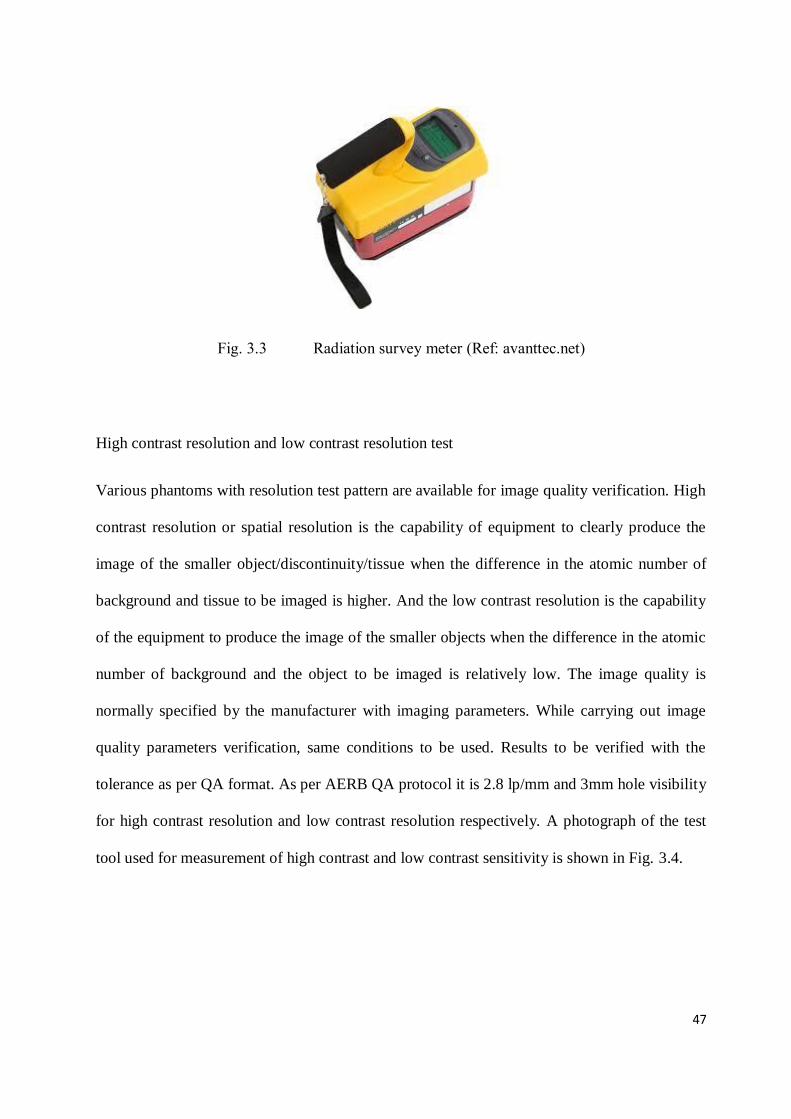
47
Fig. 3.3 Radiation survey meter (Ref: avanttec.net)
High contrast resolution and low contrast resolution test
Various phantoms with resolution test pattern are available for image quality verification. High
contrast resolution or spatial resolution is the capability of equipment to clearly produce the
image of the smaller object/discontinuity/tissue when the difference in the atomic number of
background and tissue to be imaged is higher. And the low contrast resolution is the capability
of the equipment to produce the image of the smaller objects when the difference in the atomic
number of background and the object to be imaged is relatively low. The image quality is
normally specified by the manufacturer with imaging parameters. While carrying out image
quality parameters verification, same conditions to be used. Results to be verified with the
tolerance as per QA format. As per AERB QA protocol it is 2.8 lp/mm and 3mm hole visibility
for high contrast resolution and low contrast resolution respectively. A photograph of the test
tool used for measurement of high contrast and low contrast sensitivity is shown in Fig. 3.4.
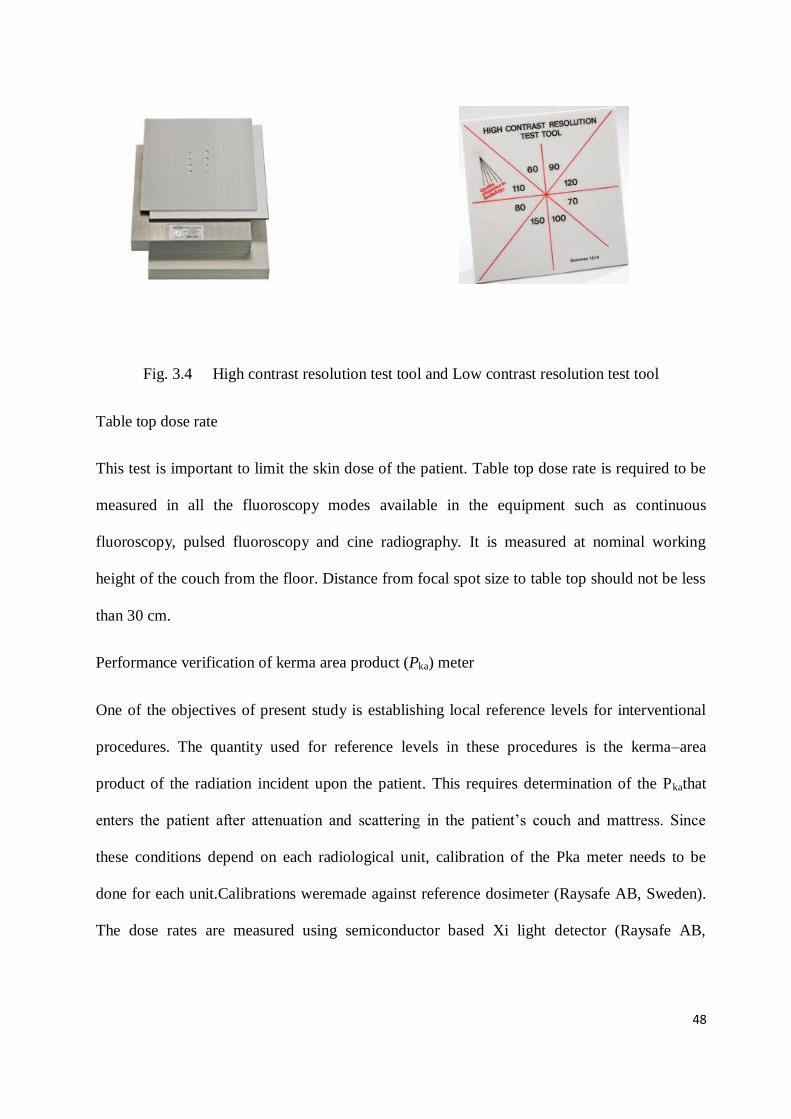
48
Fig. 3.4 High contrast resolution test tool and Low contrast resolution test tool
Table top dose rate
This test is important to limit the skin dose of the patient. Table top dose rate is required to be
measured in all the fluoroscopy modes available in the equipment such as continuous
fluoroscopy, pulsed fluoroscopy and cine radiography. It is measured at nominal working
height of the couch from the floor. Distance from focal spot size to table top should not be less
than 30 cm.
Performance verification of kerma area product (Pka) meter
One of the objectives of present study is establishing local reference levels for interventional
procedures. The quantity used for reference levels in these procedures is the kerma–area
product of the radiation incident upon the patient. This requires determination of the Pkathat
enters the patient after attenuation and scattering in the patient’s couch and mattress. Since
these conditions depend on each radiological unit, calibration of the Pka meter needs to be
done for each unit.Calibrations weremade against reference dosimeter (Raysafe AB, Sweden).
The dose rates are measured using semiconductor based Xi light detector (Raysafe AB,

49
Sweden) dosimeter. Unfors Light detector calibration is traceable to PhysikalischTechnische
Bundesanstalt (PTB), Germany, with calibration uncertainty of 2%.
The calibration has to account for the differences between the Pkadisplayed by the transmission
chamber placed on the collimator and the Pkaof the radiation incident on the patient. These
differences are due tothe attenuation and scattering in the patient’s couch and mattress, Energy
dependence of the transmission chamber (which usually contains metal electrodes),
inhomogeneity of the beam throughout the cross-section. Extra focal radiation and radiation
scattered in the collimator and filters, which may cross the Pka meter but not reach the patient.
[IAEA SRS 59]
The calibration factor is the ratio between the air kerma–area product for the radiation that
actually incidents on the patient and the value displayed by thePka meter. The beam has been
attenuated in the couch and mattress and there is some scatter radiation produced in the couch
and mattress, but there should not be backscatter radiation from the patient or phantom.
𝐾 = 𝐾ref .A
𝑃ka (3.4)
Where:
- k is the calibration factor to be applied to the transmission chamber to obtain the
patient’s Pka;
- Kref is the air kerma value measured by the reference chamber on the top of the patient’s
couch and mattress;
- A is the area that can be determined by exposing a film placed on the table top.
The distance from the tube to the table top should be similar to the one used in practice for an
average patient. The distance of the imagereceptor (flat panel detector) to the reference

50
chamber should be sufficient to minimize the backscatter radiation from the copper absorber
reaching the referencechamber.The values of the measurements were recorded.
Everymeasurement was performed three times and the averagewas taken for calculation
purpose.
Fig. 3.5 Measurement set-up of kerma area product (KAP) (Ref: slideshare.net)
Fig. 3.6 Exposed film for area measurement in the measurement of KAP
Area (A) of exposure was determined by placing a film on the table top. The collimation of
about 100 cm2
at the level of the film was selected. Exposures were made and respective
readings of auto selected kVp, reference dosimeter reading (mGy), displayed values of
KAP(µGy.cm2) and area of the exposed films (cm
2) are noted. The films were scanned and the
field sizes were evaluated.

51
Shielding adequacy of protective accessories
Lead Aprons, Gloves, Gonad and Thyroid shields were tested in the fluoroscopy mode using
survey meter. Sufficient number of measurement points was used for verification of any
defects such as breaks, cracks, porous or discontinuities. All the protective accessories shall be
checked periodically at least annually for its uniform shielding adequacy. Precaution should be
taken in the storage of protective accessories so that it should not get folded during storage.
Cracks in the lead lining can develop at the fold, reducing the useful life of the apron. It should
not assume that brand new aprons, gloves, etc. contain no defects. Visual examination is not
sufficient to ensure integrity of shielding. New aprons, gloves, etc. should also be examined
under x-ray immediately upon arrival and returned to supplier if defects are found.
Fig. 3.7 Protective eye wear and protective aprons
(Ref: goggles-medicalexpo.com, apron- xenashield.com )
3.5 Results and discussion
Licensed interventional radiology facilities were selected for studying the status of quality
assurance and review the stability of various exposure parameters and equipment components.

52
The list of facilities and details of equipment tested are given in Table 3.2. Before every
planned QA, equipment warm-up was done by giving few exposures to the phantom with
dosimeter. After stabilizing the output and exposure parameters QA was carried out. The QA
results of 39IR facilities are analysed and summary is provided in Table 3.3.
Table 3.2List of interventional radiology equipment models for which performance verification
was carried out
Sr.No. Equipment model Maximum
kVp
Maximum
(mA)
Manufacturer No. of
units
1 Artis Zee FMSC 125 800 Siemens 11
2 Innova 2100 IQ 125 1000 Wipro GE 2
3 Allura clarity family 125 750 Philips 3
4 Innova IGS 520 125 1000 Wipro GE 4
5 Allura Xper FD 10/20 125 1250 Philips 7
6 Artis Q 125 1000 Siemens 4
7 Intuis 125 1000 Philips 2
8 Axiom Artis Zee Biplane 125 800 Siemens 1
9 Axiom Artis Zeego 125 800 Siemens 1
10 Azurion 7 M20 125 813 Philips 1
11 Allura Centron 125 813 Philips 1
12 Innova-2000 125 1250 Wipro GE 1

53
13 Allengers Life FP 150 800 Allengers 1
Table 3.3 Summary of quality assurance tests results
Sr.
No
Test parameter Tolerance Compliance Range of observed
values
Remarks
1 Accuracy of operating
potential (kVp)
± 5 88 % 78 – 87 (80 kVp)
96 - 106 (100
kVp)
---
2 X-ray tube current
(mA) linearity
CoL ≤ 0.1 94 % 0.01 – 0.14 ---
3 Accuracy of timer ± 10 % 100 % 430 ms to 510 ms
( 500ms)
---
4 Output consistency CoV ≤ 0.05 92 % 0.003 – 0.06 ---
5 High contrast
resolution
2.8 lp/mm
should be
visible
100 % 4 lp/mm to 6
lp/mm
---
6 Low contrast
resolution
3mm hole
should be
visible
95 % 2mm to 5mm ---
7 Table top dose rate
(continuous
fluoroscopy)
≤ 5 cGy/min 97 % 3.5 cGy/min to 5.7
cGy/min
---
8 Table top dose rate
( AEC/pulsed
fluoroscopy)
≤ 10 cGy/min 91 % 7.8 cGy/min to
14.5 cGy/min
---
9 Table top dose rate
(for cine radiography)
≤ 20 cGy/min
46 % 16 cGy/min to
38cGy/min
It is
recommen
datory
10 X-ray tube leakage ≤ 115 mR in
one hour
100 % 22 mR to 38 mR in
one hour
---
11 KAP meter
performance
± 20 % ± 52 % --- Recomme
ndatory
10 Protective apron
shielding adequacy
--- --- --- satisfactor
y
11 *Compliance to
operational safety
requirements
--- 70 % --- ---
12 Status of Patient dose
monitoring and
recording
--- 20 % --- Poor
complianc
e
13 Patient specific
checklist
--- 40 % ---

54
*Compliance was verified against a checklist of five parameters (use of protective
accessories, use of TLD, patient specific checklist, periodic QA status, involvement of
RSO)
Conventionally, measurement of accuracy of exposure parameters such as operating potential,
operating current and exposure time were considered as important parameters in the quality
assurance. All of these parameters were found to be in good compliance with the regulatory
limits. Although in the era of digital imaging, equipment selects the exposure parameters with
a check exposure considering the attenuation of the patient. It uses different kV and mAs for
various angulations based on antero-posterior and lateral orientation of the patient and entrance
beam. Hence a small deviation in the displayed parameters than selected does not impact the
image quality and radiation safety of the patient. Measurements have been carried out for a
range of kVp values frequently used in the IR procedures i.e. 70, 80, 90, 100,110 and 120. It
was observed that up to 100 kVp the performance of almost all equipment (about 88% ) were
within prescribed tolerance however some deviations observed for higher kVp stations.
Linearity of mA station was measured in the range of 150 mA to 700 mA which was noted for
most of the procedures recorded. Linearity of current was found to be in compliance (94%)
compared with accuracy of kVp. Timer accuracy was measured in the range of 100 ms to 2000
ms. Accuracy of exposure time measurement was found to be in compliance with the
regulatory limits of ± 10 % for all the equipment.
Output consistency in terms of coefficient of variation was measured at 80, 100 and 120 kVp at
different mAs values and found to be within the tolerance for 92 % of the facilities. This is one
of the important parameters to verify reliability of the equipment performance because it can
be affected by deviation in any of the exposure parameters.

55
Image quality tests for high contrast resolution and low contrast resolution were carried out
using line pair phantom and low contrast resolution phantom made up of small air holes in the
aluminium plates of 2 cm above and below. Tests were performed using perspex phantom for
patient simulation. The results of high contrast resolution were found to be in close compliance
than low contrast resolution which is in line with the practice requirement.
Table top dose rate was measured for two different modes provided in the system. i.e.
fluoroscopy mode and cine radiography mode. Table top dose rate gives idea about exposure
time in which skin reactions will be probable using threshold values of skin reactions. The
table top dose rate for pulsed fluoroscopy mode was found to be within the tolerance for 91 %
of equipment and the range was from 7.8 cGy/min to 14.5 cGy/min. For cine fluorography
mode, mAs goes to very high values in addition to higher frame rates of 12 -15 frames/sec.
Hence most of the equipment were shown much higher values of dose rate than the
recommended tolerance. For obtaining good quality images of the moving organ like heart the
dose rates are normally observed to be very high however cineradiographic mode is used for
smaller time compared to fluoroscopy mode hence in normal cases patient does not show any
skin reactions.
X-ray tube leakage was measured as a built-in safety feature of the equipment and found to be
well within the tolerance for all IR equipment.All the above tests were part of the standard QA
protocol prescribed by AERB. These tests seem to be adequate to provide confidence that the
equipment performance is reliable and satisfactory to provide clinically acceptable image
quality with optimum dose to the patient. However, considering the high hazard potential of
interventional radiology practice, another important parameter required to be included in the

56
test protocol is performance of KAP meter in terms of dose parameters displayed on the
monitor.
During the work for establishment of Diagnostic reference levels in the selected cardiology
procedures it was required to collect and analyse the system displayed data given by KAP
meters. Hence a method has been established and followed to verify KAP accuracy and
consistency. For this purpose, a piece of Gafchromic XR-RV3 film (15 cm X 15 cm ) and Xi
dosimeter was placed at 60 cm from focal spot. Irradiated portion of film exposure provided
the area (cm2) and dosimeter provided the dose reading. Using the measured values of Kerma
and area, KAP is calculated and compared with system displayed KAP values. The
recommended performance was ± 20 %. It was noted that 40 % of the facilities were showing
its performance within ± 35 %. All these facilities were advised to calibrate their KAP meter. It
was observed that all these equipment were procured about 3-4 years back, however all the
recent installations where the KAP meter was procured about a year back were in good
compliance with recommended values.
The important outcomes of the technical survey of IR equipment for improving radiation safety
culture in the interventional radiology practice were:
i. Inclusion of KAP performance verification test in the periodic QA protocol.
ii. Specifying the frequency for calibration of KAP meter
iii. Need for patient dose audits at a specified frequency
iv. Mandatory training requirement for the IR staff regarding QA and dose display
parameters

57
The recommendations with supportive data will be provided to national regulatory authority
AERB for consideration in revising regulation in the IR practice.
3.6 Conclusions
The QA test results for all the facilities were found to be satisfactory and implies the adequacy
of QA frequency of once in two years. It is recommended that IR facility should develop a self-
assessment checklist and verify its own performance against standard operating procedures via
internal audit. The team for this purpose should consist of service personnel, medical physicist,
technologist and medical professional (doctor) for effective optimization of protocols.
For implementation of patient dose monitoring and recording, the revision of established QA
protocol is necessary and the same has been proposed here specifically by incorporating
verification of KAP meter performance.
The technical audit of interventional radiology facilities is an important tool to verify the
various safety aspects of the interventional radiology suit. This includes overall safety aspects
such as built in safety design requirements, performance of the equipment, compliance to the
operational safety requirements, patient dose data monitoring system, awareness of the medical
professionals associated with these procedures, patient follow up, record keeping, self-
assessment and compliance to the local regulations. The quality assurance studies and technical
survey of 39 IR facilities shows that, there is lot of scope for improvement in the radiation
safety status of the facility for patient, medical professionals and confidence to the regulatory
body regarding its operation.
*****

58
Chapter 4
Patient dosimetry in interventional radiology-Skin dose measurements using Gafchromic XR RV3 film
4.1 Introduction
Fluoroscopically guided interventional procedures have become a vital tool in the diagnosis
and treatment of vascular and non-vascular diseases. However, the clinical complexity leads to
the higher procedure time and subsequently increases the risk of serious skin injury. Various
methods have been developed to estimate or measure the skin dose received by patients during
such procedures. These methods include the use of thermoluminescent dosimeters (TLDs),
radiochromic film, metal-oxide semiconductor field-effect transistors (MOSFETs), kerma-
area-product (KAP) meters and software-based dose calculators. Use of TLDs is a laborious
methods, positioning of dosimeter is difficult and there is a probability of missing some of the
high dose points, if not appropriately placed. Also, many of the TLDs are not tissue equivalent
and may need various correction factors. There are many limitations for using KAP values for
skin dose estimation as it is highly area dependent. Amongst all, radiochromic film offers high
spatial resolution, large surface area (e.g., 14 in.×17 in.), and is easy to place under the patient,
making it well-suited to measure skin dose during fluoroscopy. In addition, radiochromic film
is self-developing and insensitive to visible light, making it easy to work with during analysis,
and has been shown to have acceptable precision and accuracy for clinical measurements of
skin dose.

59
In the present study the skin entrance dose measurements were carried out in 39 procedures of
coronary angiography (CA) and 25 procedures of percutaneous transluminal coronary
angioplasty (PTCA) using XR RV3 films.
4.2 XR-RV3 dosimetry film
XR-RV3 film is a reflective-type film consisting of five layers, including an opaque white
backing. The five layers are composed primarily of carbon, hydrogen, and oxygen. The active
layer contains small quantities (less than 2% by mass) of lithium, nitrogen, and chlorine, while
the opaque white polyester layer contains quantities of sulphur (less than 4% by mass) and
barium (less than 16% by mass). The active layer thickness was reported to vary by less than
5% and the thicknesses of other layers were estimated to vary by less than ±20%. The
elemental composition was reported to vary slightly between batches. The effective Z of all the
layers of the XR-RV3 film combined is approximately 7.3.
Fig. 4.1 Structure of XR-RV3 dosimetry film (Ref: efie.gr)
The large photoelectric cross-section of barium in the kilovoltage x-ray energy range used
during fluoroscopy results in a high yield of anisotropically ejected, long-range secondary
electrons. Because of the high probability of photoelectrons generated in the barium-containing
white layer of the film with ranges sufficient to reach the active layer, the orientation of the
film in relation to the incident x-ray beam may affect the dose deposited in the active layer.

60
Manufacturer of the film, International Specialty Products (ISP), Wayne, NJ, USA suggests
that XR-RV3 reflective films to be used with the white side of the film facing the x-ray source.
4.3 Materials and methods
4.3.1 Film calibration
GafChromic XR-RV3 dosimetry films from ISP, Wayne, NJ, USA were used for patient peak
skin dose measurements. The film was calibrated [McCabe et al., 2011] with a type approved
fluoroscopy machine (Polydoros, Siemens: 125 kV, 800 mA) at the beam energy normally
used during the procedure i.e. 80 kV and filtration of 3.5 mm of Al. The equipment
performance was verified using calibrated dosimeter and kV meter. A phantom of PMMA
(25x25x20) cm was used to simulate the patient. The dose rates were measured using
semiconductor based Xi light detector (Raysafe AB, Sweden) dosimeter. Unfors Xi Light
detector calibration is traceable to international standards PhysikalischTechnische
Bundesanstalt (PTB), Germany, with calibration uncertainty of 2%. To increase the dose rates,
focal spot to film distance of 50 cm was used. Sufficient time gaps were given between the
successive exposures to allow cooling of x-ray tube. Six air kerma values (150 , 500, 1000,
3000, 4000, 5000 mGy) and one unexposed background value were used to create the
calibration curve for 80 kVp beam quality “Free-in-air” indicates that the calibration films
were exposed to the primary x-ray beam with minimal x-ray scatter. The film was cut in to
pieces of 6cm X 6 cm prior to experiment, with extra care to protect it from any physical
damage. The films were placed at the centre of the phantom for simulating the actual exposure
conditions with patient. Field size of 10 cm X 10 cm is used for exposure. The films were
scanned using Epson Expression 1000XL scanner in reflection mode. 1000XL is white light
scanner having spatial resolution better than 50 microns. The film reflective density to air

61
kerma calibration curves was constructed. The response of Gafchromic film to exposure
depends on film orientation and delay between irradiation and readout time and x-ray energy.
The film calibration curve is shown in Fig 4.2.
Fig. 4.2 Doseresponse calibration curve of GafChromic XR‑ RV3 film for 80 kV x-ray
4.3.2 Performance verification of interventional radiology equipment
The equipment performances were verified before starting these studies. The important
parameters of performance i.e. operating potential accuracy (± 5 kV), output consistency
(Coefficient of variation ≤ 0.05), contrast resolution (2.8 lp/mm), table top dose rate (≤ 10
cGy/min) and accuracy of KAP (within 20%) was verified using calibrated kVp meter and
dosimeter . The numbers in the parenthesis are tolerance values of the parameters above as per
AERB QA protocol for x-ray equipment. All the parameters were found within the permissible

62
limits. The periodic performance report (quality assurance report) was satisfactory at both the
catheterization laboratories.
4.3.3 Peak skin entrance dose (PSED) measurements
The calibrated films were used for measurement of peak skin dose in the CA and PTCA
procedures. Film was positioned on the patient table under the patient, in a position to intercept
all the x-ray beams entering the patient with postero-anterior (PA) and oblique projections. The
contribution from lateral field was not covered with this set up but this projection is rarely used
in cardiac procedures. Film darkening includes back scatter, beam orientations and field non-
uniformities. The only correction factor necessary is the conversion from entrance surface air
kerma (Ke) to absorbed dose in the skin. As an approximation, recorded values are to be
multiplied by 1.06 to find absorbed dose to skin [IAEA-SRS No.59]. Skin dose measurements
were carried out for 39 cases of CA and 25 cases of PTCA at two hospitals in Mumbai. Study
included both male and female patients. In this study, the complexity index and variation of
dose with the weight of the patients or body mass index (BMI) were not considered as most of
the selected procedures were standard (simple to normal) procedures and patient weights were
within the range of 65-85 kgs. The interventional radiology equipment used for these
procedures was Artis Zee and Axiom Artis both Siemens make. The equipment are type
approved performances were found to be within the AERB tolerance limits. The performance
of KAP meter was compared with the dosimeter and found to be within ± 20 % [James et al.,
2014]. The films were cut as per the size of the patient and placed below the patient in the way
similar to that of calibration set up (white color facing the source). The films of sufficiently
larger size were used to cover the overlapping of AP-PA and oblique orientations.

63
A unique film number was allotted for every individual patient for their identification. The
details of patient and procedure such as patient age, gender, average kVp, fluoroscopy time (FT
in mins), frame rate, Pka (µGy-m2), Ka (mGy) and no. of acquisitions were recorded with their
respective film numbers. The exposed films with variations in the density are shown in the fig.
4.3. The films were then scanned after 24 hours as per calibration conditions. The reflective
density of the film was recorded using Epson Expression 1000XL scanner. The density
distribution shown in figure 4.3 represents the distribution of dose in the field. Respective
values of air kerma (mGy) were noted from the calibration curve generated earlier.
Figure 4.3 (a) Figure 4.3 (b)
Fig. 4.3 Sample of the film exposed for skin dose measurement during (a) coronary
angiography and (b) percutaneous coronary intervention procedures
4.4 Results
Patient and procedure parameters were recorded along with peak skin doses. The age range of
the patients on which measurements were carried out was 28 years to 86 years. The kVp values
recorded were within 76 to 92 kVp. Frame rate of 15 frames/second was used. The recorded
values of Pka, Ka and measured peak skin dose in CA and PTCA procedures are given in Table
4.1a and Table 4.1b. The range of recorded Pka values for CA and PTCA is 5.17 to 84.69
Gy.cm2 and 15.65 to 172.25 Gy.cm
2 respectively. The range of Ka values for CA and PTCA is

64
83.5 to 1127 mGy and 212 to 3242 mGy respectively. The peak skin dose measured for CA
and PTCA using gafchromic XR-RV3 films ranges from 48.2 to 740 mGy and 84 to 1242 mGy
respectively. The correlation of various exposure parameters with measured peak skin dose
was seen.
It is observed that the PSED is least correlated with FT. The correlation between Ka and
measured peak skin dose is shown in Fig 4.4a and Fig 4.4b for CA and PTCA respectively and
the co-relation of Pka with PSED is shown in Fig 4a and 4b for CA and PTCA procedures
respectively.
Table 4.1a. Summary statistics for coronary angiography (CA) procedure
N Mean Median SD Range 75%
Age (Years) 39 55.4 52 8 38-86 55
Fluoroscopy Time (Mins) 39 4.41 3.3 3.27 0.6-15.5 6.5
Cumulative Air Kerma (mGy) 39 485 430 254 83.5-1127 658
DAP PkA(Gy.cm2) 39 21.26 14.16 17.82 5.17-84.69 27
Peak Skin Dose (mGy) 39 210.39 130.3 181 48.2-740 320
Table 4.1b. Summary statistics for percutaneous transluminal coronary angioplasty
(CA+ PTCA) procedures

65
N Mean Median SD Range 75%
Age (Years) 25 54.6 52 12.75 28-80 64.5
Fluoroscopy Time (Mins) 25 10.48 8.1 8.55 0.9-35.6 13.55
Cumulative Air Kerma
(mGy)
25 1294.79 994.8 932.34 212-3242 1949.5
DAP PkA(Gy.cm2) 25 70.28 78.9 52.16 15.65-172.25 110.54
Peak Skin Dose (mGy) 25 490.68 319.81 368.28 84-1242 801.47
Fig. 4.4a Correlation between Cumulative air kerma (Ka) and measured peak skinentrance dose
(PSED) using XR-RV3 film for CA procedures.
PSED = 41.265e0.0027 Ka
R² = 0.836
0
100
200
300
400
500
600
700
800
900
1000
0 200 400 600 800 1000 1200
Pea
k Sk
in E
ntr
ance
Do
se, m
Gy
Cumulative Air Kerma, mGy

66
Fig. 4.4b Correlation between Cumulative air kerma (Ka) and measured peak skin entrance
dose (PSED) using XR-RV3 film for PTCA procedure
Fig. 4.5aCorrelation between KAP (Pka) and measured peak skin entrance dose (PSED) using
XR-RV3 film for CA procedure.
PSED = 0.3607 Ka + 23.676
R² = 0.833
0
200
400
600
800
1000
1200
1400
0 500 1000 1500 2000 2500 3000 3500
Pea
k sk
in e
ntr
ance
do
se, m
Gy
Cummulative Air Kerma, mGy
y = 7.962 Pka + 41.054R² = 0.608PSED
0
100
200
300
400
500
600
700
800
0 10 20 30 40 50 60 70 80 90
Pea
k sk
in e
ntr
ance
do
se ,
mG
y
KAP, Gy-cm2

67
Fig. 4.5bCorrelation between KAP (Pka) and measured peak skin entrance dose (PSED) using
XR-RV3 film for PTCA procedure.
4.5 Discussion
The overall radiation risk to the patient in interventional cardiology procedures is attributed by
stochastic risk of developing malignancy and deterministic risk of skin injury to the patient.
The risk of cancer induction from medical imaging procedures is largely unknown but it is
related to the cumulative effective dose received from imaging procedures. The effective doses
can be estimated using the tissue weighting factors with the cumulative dose or Pka values. The
conversion factors are already published in the literature. However, the risk associated with
coronary heart disease itself and the procedure of coronary angiography are relatively high
compared to the hypothetical additional lifetime risk of malignancy in patients undergoing
different radiological cardiac diagnostic procedures.
KAP values are the indicative of stochastic risk to the patient but it has very poor correlation
with the peak skin dose as the large dose received in small area and small dose spread over the
PSED = 6.0813 Pka + 63.261
R² = 0.742
0
200
400
600
800
1000
1200
1400
0 50 100 150 200
Pea
k sk
in e
ntr
ance
do
se, m
Gy
KAP, Gy-cm2

68
large area of the skin will show the similar values. However, skin reactions will be highly
dependent on the spread of the dose in the skin area. The KAP values can be used to estimate
the effective dose for Adult patients using conversion factor as1 Gy.cm2 (PkA) yields 0.18 mSv
effective dose [ IAEA Safety Reports Series No.59].
Another quantity displayed on the system during and after the IR procedure is Cumulative Air
Kerma at interventional reference point (IRP).
Fig. 4.6 Schematic of Interventional Reference point
Here the reference point may lie inside the patient, outside the patient or nearly on the skin of
the patient depending on the site of procedure and thickness of the patient. This point dose
calculation does not take into account the angulations used during the procedure. However, in
the absence of any direct method for skin dose measurement the quantity cumulative dose is
used as surrogate for estimation of skin entrance dose.

69
In addition to PKA measurements, radiochromic films can be used on few patients submitted to
cardiac procedures to determine the skin absorbed dose distribution. Film has the advantage
that the readout is directly related to the radiation that enters locally on the skin, includes
backscatter and is practically independent of the beam projection angle. The only correction
factor necessary is the conversion from entrance surface air kerma (Ke) to absorbed dose in the
skin. As an approximation, multiplying the recorded entrance surface air kerma (Ke) by 1.06
renders the estimated absorbed skin dose[IAEA Safety Reports Series No.59]. In the present
study, as the films were calibrated with phantom, correction factor was not used with the dose
recorded by the films.
Influence of operator on patient dose
Operator can influence Pka in mainly three ways. Optimizing beam on time, careful collimation
of the beam to the region of interest and minimizing source to image distance (SID). The
degree of beam collimation can be estimated by the ratio of Ka and Pka. The ratio can be used to
study the impact of collimation. Increasing SID simultaneously increases Ka and Pka. However
lowering the couch height by reducing the SID causes the higher dose rates at the skin
entrance. Hence it should be selected judiciously. Increased Pka usually result in increased
operator exposure.
It appears that although CA and PTCA are the most common procedures all over the world, the
procedures are standardized and not expected to result in the deterministic skin injury.
However, for optimization of the radiation dose incurred, every institution needs to establish
the local DRLs for common procedures and review the radiation dose by comparing among
various practitioners for improving safety culture.

70
4.6 Conclusions
Radiochromic XR-RV3 films were used for PSED measurements. Sample study of the PSED
measurements shows that the maximum localized skin dose received in CA and PTCA
procedures are 740 mGy and 1242 mGy respectively which are well within the threshold of
skin injury and also within the internationally published values in most of the developed
countries. The measured PSED shows very poor correlation with FT. As seen in Fig. 4.4a and
4.4b. Cumulative air kerma can be used as close surrogate of skin entrance dose and are
required to be monitored for avoiding probable skin injuries in the complex IR procedures.
Such measurements are necessary, prior to establishing any DRLs to evaluate the common
procedures for its optimization.
*****

71
Chapter 5
Establishment of diagnostic reference levels
5.1 Introduction
We have seen from the international practice that, many developed countries have established
and implemented the Diagnostic Reference Levels (DRLs) for various x-ray radiographic
procedures, computed tomography procedures and interventional radiology procedures. In
interventional radiology till now entire proceduresare not covered, owing to the variations in
the complexity and vast scope of applications in the field of peripheral, cardiac and neuro-
interventional radiology. However, several papers have been published on such studies for
common interventional procedures as referred in the earlier chapter.
In India, some studies have been conducted for proposing local DRLs in the field of diagnostic
radiology for adult and paediatric patients [Sonawane et al., 2009, Sarvanakumar et.al, 2014].
Sonawane et al. has estimated Skin entrance doses (SEDs) by carrying out measurements of air
kerma from 101 X-ray machines installed in 45 major and selected hospitals in the country by
using a silicon detector-based dose Test-O-Meter. 1209 number of air kerma measurements of
diagnostic projections for adults have been analysed for seven types of common diagnostic
examinations, the proposed DRLs were compared with guidance levels published by the
IAEA-BSS-Safety Series No. 115, 1996; HPA (NRPB) (2000 and 2005), UK; CRCPD/CDRH
(USA), European Commission and other national values and found comparable. Although
there was some work carried out in the interventional cardiology field also, the data covered
was limited to individual institutions only [Uniyal et al, 2017]. It is required to cover a greater
72
number of institutions for representative reference levels in the interventional radiology
practice.
An IR procedure often involves high dose and high dose rates. Hence, there is an increased
potential to cause skin reactions to the patients in complex procedure. As per International
Commission on Radiological Protection (ICRP), DRLs help in optimizing radiological
protection in imaging procedures [ICRP-135, 2017]. It offers a method of discriminating
unusually high or low patient dose for a particular procedure. Several investigators have
reported the use of KAP (Pka) and cumulative air kerma (Ka) values for interventional
radiology procedures for establishment of DRLs and estimation of skin doses [Bogaert et al.,
2009, Maghbool et. al., 2018, Van de Putte et.al, 2000, Kwon et. al., 2011] in complex
procedures.
A wide variety of fluoroscopically guided procedures are performed using different types of
equipment and clinical techniques, in different institutions. A comprehensive survey of the
entire field is a long-term work and will require many professional associations to be involved
with the regulatory body. Hence for developing the methodology of comprehensive patient
dose surveys a sample study was taken up. As nationwide survey needs a longer duration and
large number of data which was not possible owing to limited resources and lack of awareness
of the professionals in the field, few multispecialty hospitals in Mumbai were contacted for
collaboration and sharing of patient data. Based on the response received five hospitals were
involved in the present work.
The aim of the present study was to analyse the system displayed dose quantities Pka and
cumulative air kerma at interventional reference point (Ka) to establish local DRLs for the
selected interventional procedures.

73
As a step towards establishment of DRLs for interventional radiology practice in India, Atomic
Energy Regulatory Board (AERB) has made mandatory that kerma area product (KAP) meters
shall be available with every IR equipment for monitoring and recording of patient doses
during the procedure(AERB safety code SC/MED-2). However, DRLs are not yet mandatory
for IR facilities in India.
In this work, a sample study was performed for selected procedures in cardiology. A
systematic plan was prepared for data collection and analysis. The interventional radiology
staff at all the five institutions was not aware aboutradiation safety and patient dose data
monitoring & recording requirements.
5.2 Materials and methods
The sample study was carried out involving five hospitals in Mumbai. Hospital representatives
were trained for further communications in this work. Following are the steps involved in the
process.
Selection of hospitals
The selection of hospital was based on the availability of radiological safety officer (RSO) and
interventional radiology equipment with flat panel detector to maintain uniformity of data. In
these hospitals no such type of projects was carried out earlier. All the five hospitals have more
than 3-4 consultant cardiologists. The facilities and equipment selected for proposed study are
as given in Table 5.1.

74
Table 5.1List of interventional radiology systems included in this study
Facility id Equipment Make
H-1 Artis Zee FMSIR Siemens Ltd., Germany
H-2 Artis Zee Siemens Ltd., Germany
H-3 Innova 2000 Wipro GE Medical Systems, Bangalore
H-4 Artis Zee Siemens Ltd., Germany
H-5 Intus Philips Healthcare, Netherlands
5.3 Selection of procedures
Initially data has been collected for various procedures in cardiology, peripheral interventions
and neuro interventions. Later, based on the observed frequency, procedures performed on
coronary arteries were emphasized. Therefore, two representative procedures were selected:
Coronary Angiography (CA) - a diagnostic procedure, and percutaneous cardiovascular
intervention (PCI) - a therapeutic procedure. These are also the most prevalent categories of
fluoroscopically guided invasive procedures around the world.
5.3.1 Coronary angiography/ arteriography (CA)
Coronary angiography is an invasive procedure that is carried out by puncturing a peripheral
artery. A catheter is advanced through the arterial branches to the heart. By injecting an
iodinated contrast material, it is possible to selectively identify the lumen of each coronary
artery. In order to obtain optimal images of the arterial segments, different projections are done
from the left- and right-hand sides of the patient, with cranial or caudal angulations as a means
to obtain a diagnostic view of the coronary artery. Usually, series of six to eight

75
cinefluorographic runs are acquired for the left coronary artery, and two to four
cinefluorographic runs are acquired for the right coronary artery. Any bypass grafts are also
imaged. In most cases, the procedure is completed by imaging the left ventricle in the right
oblique projection and in the left oblique view when required by the clinical condition of the
patient [IAEA SRS 59].
5.3.2 Percutaneous transluminal coronary angioplasty (PTCA)
In this procedure, coronary artery stenosis and occlusions are treated using angioplasty
(balloon) catheters. A percutaneous approach is used, with puncture of a peripheral artery. The
ostium of the coronary artery of interest is catheterized selectively using a guiding catheter.
Through the guiding catheter, a guide wire with a very flexible distal tip, designed to be
manipulated easily and safely in diseased vessels, is advanced through the area of stenosis. In
some cases, is not easy to cross the stenosis or even to achieve a stable position in the coronary
ostium as a consequence of anatomical variations among patients. An angioplasty catheter with
a balloon diameter proportional to the size of the normal artery is placed in the stenotic
segment over the guide wire and through the guiding catheter. The balloon is inflated with a
contrast material solution to reach a pressure level at which the stenosis disappears. The
procedure is complemented by insertion of a metallic prosthesis (stent), which is introduced to
the area of the lesion in a very similar manner to that of the balloon catheter. There are clinical
circumstances in which the stent is placed in a stenotic coronary artery without pre-dilation of
the lesion. Depending on the particular circumstances, two or more arteries, each with two or
more lesions, may be treated in the same session.
Patients may be scheduled for a combined CA and PTCA procedure. This generally occurs
when the patient’s history of non-invasive cardiac testing indicates a significant possibility of

76
coronary artery disease or if previous CA images are inadequate. A single combined procedure
is planned and the patient is prepared to have an immediate PTCA procedure if indicated by
the results of the CA procedure. In case CA result is negative, no further procedure is carried
out [IAEA SRS 59].
5.3.3 Percutaneous cardiovascular intervention (PCI)
PCI is defined as any type of interventional procedure performed on the coronary arteries.
These procedures may or may not include a partial or complete CA procedure performed in the
same setting. Fluoroscopy is used to place the catheters and to monitor the procedure. There
are regional, institutional and individual variations on the definition of what views comprise a
standard study. Additional views are often required if the standard study provides insufficient
information to reach a clinical decision. Thus, there is a range of variability in the images
collected during the performance of this procedure. PCI procedures are highly tailored to the
clinical condition of the individual patient. Within this category one finds procedures ranging
from the simple treatment of a single discrete lesion to a complete endovascular reconstruction
of the entire coronary artery system. If the diagnostic angiogram is positive, the PTCA is
usually performed immediately. Such combined procedures require more exposure than a
simple diagnostic study or a separate simple PTCA, but usually require less radiation than that
needed to perform two independent simple procedures [IAEA SRS 59].
5.3.4 Performance evaluation of interventional radiology equipment
The variation of patient exposure and clinical image quality is a result of combination of
performance of the imaging equipment, selection of its modes of operation, and the complexity
of the procedure. PMMA (poly-methyl-meth-acrylate) phantom of thicknesses 30cm x 30cm
x20 cm was used for performance evaluation of the IR system. The key dosimetric parameters

77
are patient entrance surface air kerma (Ke), related image quality parameters i.e. high contrast
detectability, spatial resolution, low contrast detectability and automatic exposure control
(AEC) system. Automatic dose rate control systems are designed to image tissue and materials
such as stents and iodinated contrast media in specific clinical contexts. Air kerma rates are
best measured by placing only the air kerma meter and an appropriate thickness of PMMA in
the beam. Equipment performance evaluation included calibration of all available dosimetric
displays (e.g. Ka, Pka) and the accuracy of operational displays (e.g. kV, mA, time). The
performance of the equipment was found to be well within the tolerance limits as per AERB
quality assurance protocol.
5.3.5 Complexity index
With increasing awareness about the use of DRLs in the field, many studies are undertaken in
various countries. Considering the challenges faced in classification of procedures, wide range
of observed dose parameters and difficulty in arriving at some reference values for common
interventional procedures, there implies a need to take into account another important factor of
complexity index, which is measure of clinical complexity involved in the procedure.
However, as the present study has been performed on a small scale and without much support
of physicians to understand the clinical aspects of the individual procedure the complexity
index was not considered in this study.
5.3.6 Effect of patient weight on the results
Entrance surface air kerma, Ke, depends on the patient thickness. This is particularly true when
automatic exposure control (AEC) is used to keep the dose to the image receptor constant,
which requires compensation for the larger attenuation of heavier patients. Fluoroscopic and
cinefluorographic patient entrance air kerma rates are decided by automatic control devices,

78
which manage beam parameters such as kVp, mA, pulse width and added beam filtration. In
this study standard sized patients were selected for data collection and weight dependent
variation in the Pka values has not been considered. Studies shows that more than 50 % patient
normally lies within the normal range of weight. Pka values vary to almost more than double as
weight increases from 50 kg to greater than 100 kg [IAEA SRS 59].
5.3.7 Patient data and local DRL
The details of patient (age, gender), procedure (CA/PCI), exposure parameters [average kVp,
fluoroscopy time (mins), frame rate (frames/sec), number of acquisitions], and system
displayed dose quantities [Pka (µGy-m2) and Ka (mGy)] were recorded. The data of 572 patients
(374 CA and 198 PCI) was recorded and analysed to calculate 75th
percentile values of Pka and
Ka. Both male and female patients were included in this study. The complexity index and
variation of dose with the weight of the patients were not considered as most of the selected
procedures are standard and patient weights were within the range of 65 to 85 Kg.
Usually, 75th
percentile of dose quantities is designated as DRL. Recently there are studies and
discussion regarding use of 50th
and 90th
percentile for establishing DRLs. However, in the
present study conventional value of 75th
percentile is used. The criteria for selection of the
percentile is decided on the basis of stage of DRL implementation. For the institutions first
time using DRLs, if 50th
percentile is established as DRL, it is likely that most of the
procedures or IR facilities may not comply and optimization will be difficult. Contrarily, if 90th
percentile is established as DRL, almost all the facilities will be complying with the established
values and identifying bad practices will be difficult and purpose of DRL establishment will be
defeated. Compared to both of the above choices, 75th
percentile is found to have a balanced

79
approach, where the facilities/procedures exceeding the value should review for possible
reduction of doses. Hence in this study 75th
percentile is usedfor establishing DRL.
5.4 Results
The kVp values recorded were within 76 to 92 kVp. Frame rate of 15 frames/second was used.
The statistics of recorded data of CA and PCI are given in Table 5.2 and Table 5.3
respectively. Data of 374 patients undergoing CA procedures were recorded from selected
hospitals and mean, median, standard deviation and 75th
percentile were evaluated.
Table 5.2Statistics of data for coronary angiography (CA) procedures
Parameters Number of
patient (N) Mean Median
Standard
deviation
(SD)
Range 75
th
percentile
Age (Years) 374 56.44 56 12.6 28 - 91 ---
Fluoroscopy
Time (Mins)
374 5.67 3.5 6.2 0.6- 31.4 ---
Cumulative
Air Kerma
Ka(mGy)
374 500.11 425.85 314.27 35.2 - 1954 590
DAP
Pka(Gy.cm2)
374 25.70 21.05 21.85 4.86 - 106.36 34.1

80
Table 5.3Statistics of data for percutaneous coronary interventions (PCI)
Parameters Number of
patient (N) Mean Median
Standard
deviation
(SD)
Range 75
th
percentile
Age (Years) 198 58.01 58 12.04 28 - 91 ----
Fluoroscopy
Time (Mins)
198 17.42 14.9 11.25 2.13 - 66.8 ----
Cumulative Air
Kerma (mGy)
198 1654.14 1454 860.85 294 - 5162 1930
DAP
Pka(Gy.cm2)
198 114.93 111.47 75.71 10.56 - 423.65 134
Table 5.4 presents the local diagnostic reference levels for coronary angiography and
percutaneous coronary intervention procedures in terms of KAP and cumulative air kerma. As
indicated earlier the DRL is 75th
percentile of the data recorded for a given procedure.
Table 5.4 Local diagnostic reference levels for coronary angiography and percutaneous
coronary intervention procedures
Procedure Coronary Angiography Percutaneous Coronary Intervention
Pka(Gy.cm2) 34 134
Ka(mGy) 590 1930
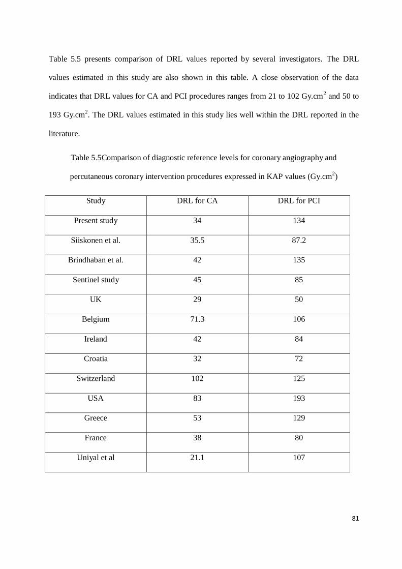
81
Table 5.5 presents comparison of DRL values reported by several investigators. The DRL
values estimated in this study are also shown in this table. A close observation of the data
indicates that DRL values for CA and PCI procedures ranges from 21 to 102 Gy.cm2 and 50 to
193 Gy.cm2. The DRL values estimated in this study lies well within the DRL reported in the
literature.
Table 5.5Comparison of diagnostic reference levels for coronary angiography and
percutaneous coronary intervention procedures expressed in KAP values (Gy.cm2)
Study DRL for CA DRL for PCI
Present study 34 134
Siiskonen et al. 35.5 87.2
Brindhaban et al. 42 135
Sentinel study 45 85
UK 29 50
Belgium 71.3 106
Ireland 42 84
Croatia 32 72
Switzerland 102 125
USA 83 193
Greece 53 129
France 38 80
Uniyal et al 21.1 107

82
5.5 Discussion
The variations in the radiation doses incurred during PCI are observed to be larger than the
variation of doses incurred in the CA procedures. The reason for variation in the doses are due
to clinical complexity involved in the procedure, number of stents implanted and skill of the
medical practitioner. The data presented in this study were collected from a few hospitals in
Mumbai. The present data can be considered as a representation of Mumbai region and the
local DRLs presented in this work can be implemented in the city. However, median of these
data may not be the representative of the practices in the country. There is a need of conducting
country wide survey for establishing national DRLs.
During course of present study, it was noted that the important parameters affecting patient
dose readings used for establishment of DRLs are, lacking of proper nomenclature and
categorization of procedure, identifying clinical complexity of procedure, grouping the data
based on Body mass index or patient weight, accuracy and consistency of dose display
quantities and importantly skill of medical practitioner. The entire cardiology team need to be
involved in generation of data, analysis, review and possible improvements in the procedure.
The uncertainty because of KAP meter performance can be reduced by periodic calibration. In
the present study, the observed variation was 20%. When setting local DRLs, each institute
should reduce this uncertainty by correcting the values with appropriate calibration coefficient.
The DRL derived in this study for coronary angiography is comparable to the values reported
by the earlier study in India and other countries, however the DRLs derived in this study for
PCI appears to be higher than the values reported from the other countries. This may be
because, the patient doses in interventional radiology procedures have not been studied
comprehensively and guidance for clinical practitioner is not available. CA being simpler

83
procedure and standardized, patient doses are more or less optimized and hence DRLs are
comparable with reported values. Introduction of flat panel technology and dose reduction
features in the recent years also have affected the patient doses [Pantos et al.,
2009].Pkavaluescan be used to estimate the effective dose for adult patients using conversion
factor as 1 Gy.cm2 (Pka) yields 0.18 mSv effective dose [IAEA SRS 59].
It appears that although these arevery common procedures all over the world many of the
procedures are not expected to result in the skin injury. Further for optimization of the
radiation dose, every institute need to establish the local DRLs for common procedures and
review the radiation dose by comparing among various practitioners for improving safety
culture. For interventional procedures it is important to understand that the reference levels are
never meant for individual patients and are to be applied with flexibility to allow higher
exposures if these are indicated by clinical judgment.
The reference levels suggested in this study as 75th percentile of Pka values can be used by the
institute for initial comparison of patient dose for optimization and can review the same after
analysis of sufficient number of procedures. It is seen that the median values of Pka i.e. 21 Gy-
cm2 for CA and 111 Gy-cm
2 for PCI are below the respective reference levels. Which implies
the acceptability of the procedures in the selected institutions.
5.6 Conclusions
The results of the present study provided useful statistical data for CA and PCI procedures.
However, the boundary between pure interventions and interventions involving some
diagnostic runs is not easy to define in clinical practice. The 75th
percentile of the dose
distributions reported here provides a reasonable set of initial values. Table 5.4 presents
suggested reference levels.

84
Individual facility should compare their mean values against these reference levels for standard
procedures only. Investigation will be required if the facility’s values are too high or too low
compromising intension of the procedure. Reference levels are expected to change over time.
They may decrease if equipment becomes more dose rate efficient or if clinical devices and
techniques become more proficient. However, guidance levels may increase if the average
clinical complexity of procedures increases. Very low patient exposure is not desirable if the
clinical purpose of the procedure is compromised. For CA and PCI, too low a dose may
indicate an incomplete procedure, inadequate image quality, low complexity or excellent
technical settings.
Based on the data analysis, an initial PCI reference level of 135 Gy·cm2 and CA reference level
of 34 Gy·cm2
is proposed. Action levels also should be established for Centres with mean
values of procedures below the action levels should investigate the quality of their procedures
and above the action levels procedures should be investigated for optimization. Till date there
are no DRLs established for these procedures in India and this study could be used as an
interim yardstick for other cardiac interventional labs in India until a large national study could
be performed.
*****

85
Chapter 6
Investigation of skin reactions in complex interventional radiology procedures
6.1 Introduction
The use of fluoroscopically guided interventional radiology (IR) procedures are rapidly
increasing as it helps in avoiding complicated invasive surgery and reduce hospitalization time
[Pantos et al., 2009]. Nevertheless, as the complexity of the interventional radiology
procedures increases, so do procedure time and concomitant cumulative skin dose, and
therefore, the risk of skin injury [McCabe et al., 2011]. Radiation-induced skin damage has
been recognized as a rare complication of fluoroscopically guided interventional procedures
[Valentin et al., 2000]. The radiation doses in the complex procedures often exceed the
threshold values for skin reactions in single or multiple procedures. Single procedure peak skin
doses of the order of several tens of Gy have also occurred during IR procedure as reported
earlier [Koenig, et al., 2001, Balter et al., 2014]. Manifestations of radiation injury to the skin
range from mild erythema at low doses to dermal necrosis or chronic ulceration at very high
doses [Koenig,et al., 2001]. Radiation skin reactions are not ‘burns’; but they occur as a result
of damage to the basal cell layer of the skin and the resultant imbalance between the normal
production of cells in this layer and the destruction of cells at the skin surface [Khanna et al.,
2013]. Erythema occurs as a result of capillary dilatation and resultant increased vascularity in
the dermis [Khanna et al., 2013]. The exposure of the subdermal lymphatics as a result of loss
of the superficial epithelium leads to moist desquamation, or after higher doses, skin necrosis

86
[Khanna et al., 2013]. It is essential that any damage is minimized, as far as possible, by
ensuring that interventions are based upon best practice and supported by evidence based
guidelines [Porock et al., 2001].
During any interventional procedure, the dose delivered to the patient is distributed over
different areas of the skin based on beam directions used in the procedure and hence skin
reactions are not observed in general. However, complex IR procedures may deliver doses
which exceed the tissue reaction threshold to some areas of skin, causing skin injuries.
Therefore, monitoring of patient doses in real-time would be helpful in predicting the
occurrence of any tissue reactions. Thresholds for the nature and severity of radiation injury
and period of its manifestation vary from patient to patient [Balter and Miller, 2014]. Patient
related factors that increase susceptibility to radiation injury include auto immune and
connective tissue disorders, hyperthyroidism, diabetes mellitus and compromised skin integrity
among others [Miller et al., 2010]. National Council on Radiation Protection and
Measurements (NCRP) recommends follow-up of patients who undergo IR procedures in
which cumulative air kerma at reference point (Kref) exceeds 5Gy in order to detect clinically
relevant skin reactions (NCRP Report, 2010). The International Electrotechnical Commission
(IEC) defines Krefas the air kerma accumulated at patient entrance reference point which lies on
the central axis of the beam, 15cm on the x-ray tube side of isocenter for isocentric IR
equipment [IEC, 2010; Miller et al., 2010]. In this study, a comparative analysis was carried
out for 6 patients who underwent complex IR procedures where Krefexceeded 5Gy, to monitor
the occurrence of skin reactions, if any. To the best of our knowledge, follow up studies of
patients who received doses with potential to cause skin reactions in interventional radiology
procedures are scarce. The objective of this study was to (i) compare the radiation induced skin

87
reactions, if any on 6 patients who underwent complex IR procedures and received Krefabove
5Gy, and (ii) experimentally validate the onset of skin reaction in one case and estimate
probable causes of such reactions.
6.2 Materials and methods
6.2.1 Patient case studies
In the present study, comparative analysis of onset of skin injury was carried out for 6 patients
(hereafter referred to as Patients #1 to #6) who underwent complex IR procedures. The
complexity of procedures is considered based on time of exposure (fluoroscopy/ cine
acquisition) and resultant radiation dose delivered. Out of six, five IR procedures were carried
out by the same interventional radiologist. Two patients (#1 and #2) reported with suspected
radiation-induced skin injury. Patient#1 developed skin reactions on the right mid forearm and
gluteal region one month after embolization procedure for treatment of pelvic arteriovenous
malformation (AVM). Dose records of patient #1 were not available in the system. The total
fluoroscopy time for this patient was 90 minutes; and total skin dose was estimated to be
approximately 8 Gy. The skin reactions were reported by the patient after a month of the
procedure. Skin biopsy test and successive investigations carried out by the hospital showed
that the patient has developed chronic radiation dermatitis (RD). Patient #2 reported skin
reddening and desquamation within 24 hours of the ventricular pacemaker implantation
procedure. The total procedure time was 101 minutes and the cumulative air kerma recorded in
the IR system was5.7 Gy. This dose was delivered from three different angulations of the C-
Arm, namely postero-anterior (PA), 300
left anterior oblique (LAO) and 200
right anterior
oblique (RAO). In this case, skin reactions were visible in the various areas of the patient skin,
not consistent with the irradiated area. Patient #3 to Patient #6 who underwent complex IR

88
procedures and received Krefexceeding 5 Gy were followed up for a period of 2 years after the
procedure to check for occurrence of skin reactions.
6.2.2 Estimation of peak skin dose
Anthropomorphic phantom and radiochromic film
The skin reactions in case of patient #2 were not concurring with the skin areas subjected to
radiation exposure. Anthropomorphic phantom based experimental simulation was performed
to estimate the peak skin dose and identify the skin areas which might have received dose
above the skin reaction threshold. The dosimetric measurements were carried out on C-arm
mount monoplane digital angiography unit (Artis Zee, Siemens, Germany) which was used for
conducting the clinical procedure on patient #2. An anthropomorphic thorax phantom
(Alderson Lung/Chest Phantom RS-320, Radiology Support Devices, USA) which extends
from the neck to below the diaphragm was used. The phantom is moulded about a male
skeleton, corresponding to the external body size of a patient, 5 feet and 9 inches (175 cm) tall
and weighing 162 lbs (73.5 kg). The materials in the phantom cavity are equivalent to natural
bone and soft tissues. Lungs are fixed in the inflated state and are moulded to conform to the
pleural cavities of the phantom. The pulmonary arteries are injected with a blood equivalent
plastic to simulate patient anatomy.
Gafchromic XR-RV3 dosimetry film (Ashland Inc. Covington, Kentucky, USA) was used to
record and measure patient skin dose during interventional procedure. The film was calibrated
in terms of air kerma in the range of 15 to1000 cGy using 80 kV x-ray beam with 3mm Al
filtration. During calibration film samples were placed on 20 cm X 20 cm X 30 cm Perspex

89
phantom to simulate patient-equivalent backscattering conditions [McCabe et al., 2011]. The
irradiated film samples were scanned using Epson Expression 10000 XL flatbed scanner.
6.2.3 Experimental set up
The performance of the IR equipment was tested using a calibrated multi-O-meter
(UnforsRaySafe AB, Sweden) before conducting the experiment. The table top dose rate of the
IR equipment was measured and verified with system displayed data. Based on the dose report
of patient#2 stored in the IR system and inputs of the interventional cardiologist who
performed the procedure, phantom exposures were carried out. The phantom was placed on the
patient table reproducing the patient position for IR procedure. Gafchromic XR-RV3films are
available in standard size of 14”x17”. A single sheet of film was cut into two sections, each of
size 7”x 8.5” for better conformity to the phantom contours and was placed adjacent to each
other on the anterior side of the chest. Film sections of size 7” x 8.5” were placed on lateral
sides of the phantom and a single film sheet of size 14”x17” was placed on the posterior side.
The phantom was irradiated using same angulations as in the case of patient #2and cumulative
air kerma values delivered in each angulation was matched as closely as possible to the values
recorded in the patient dose report. The irradiated films were scanned after 48 hours and peak
skin doses were determined using the calibration curve.
6.3 Results
Table 6.1 shows the patient age, type of interventional procedure, total fluoroscopy time and
cumulative air kerma at reference point of the 6 patients included in the present study. Patient
#1 developed radiation dermatitis which initially presented as mild form of skin damage and

90
eventually became ulcer within a period of four months after the embolization procedure (Fig.
6.1).
Figure 6.1 Skin reactions in patient #1 who underwent embolization procedure for pelvic
AVM. (A) Skin reaction on right arm after a month of the IR procedure (B) Skin reaction in the
right arm progresses (C) Skin reactions in the posterior and right lateral gluteal region (D) Skin
reactions in the right gluteal region progresses to a non-healing ulcer
Exposure parameters of experimental simulation performed to estimate the peak skin dose and
identify the skin areas which received maximum skin dose in case of patient #2 are presented
A B
D C

91
in Table 6.2. The analysis of exposed Gafchromic films showed that the lower right area of the
back where radiation fields from all the three angles overlapped received maximum dose.The
value of peak skin dose measured by Gafchromic film was 5.8 Gy. Even though this dose is
higher than the threshold dose for skin reactions, no specific injuries were observed in the area
of skin which received maximum dose. Reddening and peeling of skin of patient #2 were not
specific to the area of radiation exposure but were noticed in other parts of the body. Patient
#2also had predisposed skin condition. Patient #3 to patient #6 did not report any skin reactions
after the procedure (followed up for 2 years).
Table 6.1Details of patients and interventional radiology procedures
Patient Age Procedure Total
fluoroscopy
time
(Minutes)
No. of
cine
acquisitions
Total
cumulative
air kerma
(Gy)
Patient 1 55 Pelvic arterial
embolization 90 -- *8
Patient 2 72 Ventricular Pacemaker
Implantation 100.8 18 5.7
Patient 3 24 Uterine artery
embolisation 36.6
38
5.2
Patient 4 58 Left Colic artery
embolisation 36.7 27 7.1
Patient 5 52 Endovascular
embolization 34.3 24 5.4
Patient 6 65
Fenestrated Endovascular
Aortic Repair
322.9 60 19.9
* Estimated skin exposure
Table 6.2Operating parameters and recorded cumulative air kerma in anthropomorphic
phantom study performed to determine peak skin dose in case of patient #2

92
Projection
Fluoroscopy Cine acquisition Cumulative air
kerma
(mGy)
kV mA kV mA
PA 65 4 81 178 3990
LAO 68 3.8 85 130 684
RAO 70 3.6 87 116 1026
6.4 Discussion
Fluoroscopically guided interventional procedures are associated with a risk of radiation injury
to the skin. Many a times, complex procedures require long fluoroscopy times which may
cause significant increase inpatient skin dose. The skin dose in such cases might exceed the
threshold limits for skin reactions. The threshold dose for transient skin erythema is 2
Gy[Miller et al., 2003]. In the present study, 6 patients who received dose exceeding this
threshold limit were followed up for a period of 2 years after the completion of IR procedure.
These cases were selected to compare the radiation induced skin reactions, if any, in these
patients. Out of six, only two patients reported suspected radiation induced skin injury. The
skin injury of patient #1 was diagnosed as chronic RD through biopsy test. The initial symptom
of skin injury in the case of patient #1waserythema in the upper mid line and right lateral
gluteal region. The right arm of patient #1 was also exposed during the procedure to radiation
and skin reactions were observed on the arm as well (Fig. 6.1). The radiation induced erythema
in the right gluteal region progressed to a non-healing ulcer and hence skin grafting had to be
performed. The initial skin grafting was unsuccessful and hence the patient underwent repeated

93
skin grafting. The skin reaction on patient arm could have been avoided, if it was placed out of
the primary beam.
Patient #2 reported with reddening and peeling off skin in areas exposed to radiation as well as
unexposed areas within 24 hours of the IR procedure. An anthropomorphic phantom based
study was performed to simulate the exposures performed in the case of patient #2.The results
of the experimental study using phantom and XR-RV3 Gafchromic films enabled to identify
the area exposed to maximum radiation dose due to overlapping fields. Reported skin condition
of patient #2 was not consistent with areas exposed to radiation during the procedure. The
dermatological tests confirmed that the patient has epidermal necrolysis. Hence in the case of
patient #2 it was concluded that the skin reactions were not radiation induced. Patient #3 to
patient #6 received entrance skin dose in the range of 5.2 Gy to 19.9 Gy and there was no
reportable radiation induced skin reaction. In the case of patient #6, cumulative air kerma value
was much higher compared to other patients included in the study. However, no skin reactions
were observed in this patient. This may be attributed to the distribution of radiation dose in
different areas of the body without overlapping the separate radiation fields, thus reducing peak
skin dose [Balteret al., 2014].
The comparative analysis of 6 patients proves that the effect of radiation on patients
undergoing complex fluoroscopically guided interventional radiology procedures delivering
doses exceeding the threshold values for skin reactions is widely varying. The follow up study
in patients who received doses exceeding the threshold for skin reactions indicates that factors
other than radiation dose play a significant role in manifestation of radiation induced injuries.
Obesity, diabetes, nicotine abuse, compromised skin integrity, skin type,
autoimmune/connective tissue disease, hyperthyroidism and certain drugs are among many
factors which affect the expression and severity of the radiation injuries [Jaschkeet al., 2017].

94
Individual differences in radiosensitivity exist in human populations, which could be caused by
nucleotide variants of DNA repair genes [Matsuuraet al., 2016]. As radiation produces DNA
damage, patients with impaired cellular DNA repair capabilities are at increased risk. Patients
suffering from ataxia teleangiectasia, a rare autosomal-recessive disorder resulting from
mutations in both copies of ATM(ataxia teleangiectasia mutated) gene, are predisposed to
develop severe cutaneous complications after radiation exposure. It has been suggested that
many patients with serious and unanticipated radiation injuries may be heterozygous for the
ATM gene or possess some other ATM abnormality [Balter et al., 2010]. ATM heterozygocity
occurs in approximately 1% of the general population [Balter et al., 2010; Hymes et al., 2006].
The present study had a few limitations. In the absence of dose records for patient #1, estimate
of entrance skin dose was made from system technique factors, exposure rate during
fluoroscopy and total fluoroscopy time. Cumulative air kerma values were used as surrogate
for patient entrance surface dose for all the other cases. Since cumulative air kerma does not
include corrections for scatter contribution, C-arm angulations, rotation or table movements, it
may overestimate the skin dose. The exact cause of radiation injury induction in one patient out
of 6 patients who received similar values of radiation dose could not be verified.
6.5 Conclusion
The present study of comparison of onset of skin reactions if any, of 6 patients who underwent
complex IR procedures, concludes that individual-specific factors play a significant role in the
onset/occurrence of skin reactions. Therefore an intensive assessment and analysis of intrinsic
and extrinsic factors related to radiation sensitivity of patients prior to complex IR procedures

95
may help in preventing radiation induced skin injuries. The study also emphasize the
significance of patient positioning during IR procedures so that extraneous body parts like arms
would not be exposed in primary x-ray beam. Method of in-phantom dose measurement
simulating the clinical conditions may be used in investigation of skin injury cases reported
after complex interventional radiology procedure to identify the skin areas exposed and
determine the dose delivered.
*****

96
Chapter 7
Estimation of occupational doses in interventional radiology practice
7.1 Introduction
Monitoring of occupational doses in the radiology facilities has become important after the
introduction of fluoroscopy. The advancement in the technology has brought the better-quality
images and invention of cinefluorography made it possible to use the x-ray equipment for
guiding the catheter in the vascular and non-vascular interventional procedures. The medical
professionals performing the IR procedures and assisting staff are required to be in the close
vicinity of the patient (source of scattered radiation) during the procedure. Increasing clinical
complexity of procedures may require longer fluoroscopic duration, leading to increased
exposure to the patient as well as to the medical professionals associated with the procedure.
Health benefits of these procedures to patients are extensive and undisputable; however,
recurrent exposure to significantly high radiation doses of associated medical professionals is a
matter of concern. The knowledge about various dose reduction features and radiation levels at
various locations around the equipment in the different modes of equipment operation and
beam angulations is necessary to reduce the occupational doses. Radiation protection measures
are therefore necessary for all individuals who work in the interventional fluoroscopy suite.
This includes interventional radiologist, technologists, nurses, and anaesthesiologists (who may
be in the radiation environment only occasionally). All of these individuals may be considered
as radiation workers, depending on their level of exposure likely to be incurred and regulatory

97
requirements. Monitoring of radiation doses to radiation workers is necessary and they should
also be advised to use protection tools and accessories.
Fluoroscopically guided interventional procedures are performed in large numbers in India.
There are around 1700 licensed IR facilities performing about 50,000 procedures annually as
per data of the year 2017 taken from website of ‘The Indian Society of Vascular &
Interventional Radiology (ISVIR)’ i.e. www.isvir.org. The radiation dose received by
interventional radiologists may vary by a large magnitude for the same type of clinical case
with different patients. Recently, there has been particular concern regarding occupational dose
to the lens of the eye for interventional radiologists [Addendum to ICRP 103].
There are various methods of monitoring or estimating the radiation doses to occupational
workers. Use of personnel monitoring devices is the most common technique. However,
systematic and regular use of personnel monitoring badges is necessary otherwise estimation of
the actual dose received will be difficult. Also, many of the physicians are associated as
consultants to more than one institute and adding up of doses from all the institutions is
difficult unless the physicians themselves inform it to regulatory body or use the same
personnel monitoring badge all the time.
In the present work, for studying the trend of occupational doses to the personnel working in
the IR facility Thermo-Luminescent Dosimetry (TLD) badges were distributed in the five
institutions. It was requested to radiation professionals in the department to use TLD badges
regularly and record the respective workload in terms of patient procedure details for a period
of four months. However, due to lack of awareness and training of professionals, data collected
was not of the appropriate scientific significance. Hence the TLD doses could not be
correlated with the workload and respective personnel dose could not be estimated.

98
Later, an alternate method was used to estimate the radiation doses to the personnel working in
IR, using radiation protection survey data and workload (number of patients and KAP
values/procedure) of the particular medical professional in terms of procedures conducted. An
examination protocol is generated in the IR equipment after every procedure which gives the
details of operating potential, fluoroscopy time, number of cine runs, cumulative air kerma and
KAP delivered from various angles during the procedure. Every angulation leads to different
dose levels at medical professional’s position in the IR room. The dose delivered from a
particular angle decides weightage of that dose in the total dose received during the selected
procedure. For estimating the dose per procedure, the survey readings of simulation and KAP
delivered in various angulations from the exam protocol generated by the system was used.
This method can also be used for the investigation of excessive exposures received by the
radiation workers (for verification of personnel monitoring badge reading) retrospectively.
There are many uncertainties involved in the estimation of personnel doses in this method as
practically there may be different positions of the personnel (compared to the positions used
during radiation survey) , period of presence (full time or partial) and use of protective
accessories are the variables compared to direct personnel dosimetry using individual
monitoring badges. Similarly, NCRP Report 122 discuss about the uncertainties in the effective
dose estimation using personnel monitoring badges owing to use of various formulas and its
inaccuracies in the standardization. In this method the badges are calibrated with standard sized
phantom which also needs correction while applying for individuals considering the variations
in the weight, height etc. However, considering all the above practical limitations, there has to
be some method to be used for estimation of occupational doses for improving the safety and
ensuring the compliance to regulatory limits. In this study, an attempt was made to provide the
gross idea about the order of doses received by the individuals working in the IR facilities.

99
The objectives of this work were (i) Estimation of doses for all in-room personnel using
radiation levels and Optically Stimulated Luminescent dosimeters (OSLDs), (ii) Comparison of
occupational doses measured by OSLDs and simulation experiment and (iii) Investigation of
the contribution of fluoroscopy and cine radiographic mode of exposure using irradiation time
and dose rates.
Luminescence is a phenomenon of emission of light by certain class of materials. Among the
various categories of luminescence, thermo luminescence (TL) and optically stimulated
luminescence (OSL) are the ones in which emission of light takes place during stimulation of
an irradiated material through thermal and optical means respectively. OSL is relatively new
technique for radiation dosimetry that was originally developed for geological / archaeological
dating [Huntley et al. 1985]. Over several decades TL is being practiced as an established
method for radiation dosimetry. However, of late, in the international scenario OSL based
dosimety is being increasingly adopted in various branches of radiation dosimetry which
includes personnel and environmental monitoring, medical dosimetry etc. The reason for this
being several advantageous features of OSL over TL technique like fast and multiple readouts,
absence (no) of thermal quenching, high sensitivity and dose re-estimation in a simple manner.
OSL dosimetry thus is a viable alternative to the existing TL dosimetry program. [BARC
Newsletter BARC newsletter founder’s day special issue 2015].
7.2 Material and methods
The x-ray systems used in the study are given in Table 7.1.

100
Table 7.1 Details of interventional radiology equipment used for survey measurements
Sr. No. Model
Hospital -1 Artis Zee FMSIR, Siemens Ltd., Germany
Hospital -2 Intus, Philips Healthcare, Netherlands
Hospital -3 Artis Zee, Siemens Ltd., Germany
Performance verification of interventional radiology equipment was carried out using standard
protocols prior to conducting an extensive radiation survey of the IR facility. A tissue
equivalent phantom was used to simulate the patient. A stand with lead apron was placed at the
primary operator’s (medical practitioner) location. Two pairs of OSLDs were fixed inside and
above the apron at the chest level as shown in Fig. 7.1. Typical examination protocols of
coronary angiography (CA) and percutaneous transluminal coronary angioplasty (PTCA) were
analysed from all the three hospitals and various beam angles used in these procedures were
noted. The primary operator (cardiologist), assisting physician, technologists and
anaesthesiologists’ positions were decided with the guidance of IR staff and setting of IR
facility. Distance to all these locations was measured and noted. Radiation levels at above
positions were measured from the phantom (source of scattered radiation) for fluoroscopy and
cineradiography mode at all the locations using Xi survey meter (Raysafe AB, Sweden). The
built-in protective accessories of the IR equipment i.e. couch hanging lead rubber flaps and
ceiling suspended lead glass was in place during the radiation level measurements. Personnel
protective accessories i.e. lead apron and thyroid collar were used for primary operators’
position. At all other locations, survey meter readings were recorded without protective

101
accessories. These readings were corrected using apron transmission factor. The OSLD
measured dose values and personnel doses estimated by radiation survey at primary operators’
position were compared.
Fig 7.1 Positioning of lead apron with
stand for estimation of dose to medical
practitioner.
Fig. 7.2 Simulation experiment with phantom for
radiation survey
7.3 Results and discussion
The average radiation levels at various locations in the IR facility in fluoroscopy mode and
cineradiography mode are given in Table 7.2 and Table 7.3 respectively. It is observed from
the data in these tables that the radiation levels in fluoroscopy mode are considerably lower
than the radiation levels during cineradiography mode. Hence, small reduction in number of
cine images/time can make the considerable difference in the doses incurred compared to
curtailing of fluoroscopy time. Thus, the same should be used to extract as much information
as possible.

102
Table7.2 Radiation levels at various locations for different C-Arm angulations in
fluoroscopy mode
Radiation level in mSv/hr (fluoroscopy mode)
Angulations used during
procedures
Primary
operator (50-
70 cm from
phantom)
Assistant
physician
(1.3 m
from
phantom)
Technologist
(2m from
phantom
Anaesthesiologists
(3 m from
phantom)
AP 00,
Cranial 30 0.6 0.112 0.010 0.240
LAO 50, Cranial 25 0.7 0.28 0.021 0.7
LAO 40, Caudal 40 1.2 0.32 0.042 0.68
RAO 30, Cranial 30 0.62 0.3 0.23 0.45
RAO 30, Caudal 30 0.85 0.32 0.049 0.56
LAO 30, Cranial 30 0.9 0.39 0.035 0.6
RAO 30, Cranial 0 0.340 0.178 0.011 0.200
Lateral 90 (Right) 0.9 0.75 0.157 --
Lateral 90 (Left) 3.5 2.0 0.25 --
Average dose rate 1.06 0.51 0.089 0.49

103
Table 7.3 Radiation levels at various locations for different C-Arm angulations in cine
radiography mode
Radiation level in mSv/hr (Cine radiography mode)
Angulations used
during procedures
Primary
operator (50-
70 cm from
phantom)
Assistant
physician
(1.2 m from
phantom)
Technologist
(2m from
phantom
Anaesthesiologis
ts
(1.5 m from
phantom)
AP 00,
Cranial 30 1.39 0.380 0.032 0.7
LAO 50, Cranial 25 2.6 1.15 0.068 2.6
LAO 40, Caudal 40 3.2 1.41 0.120 2.2
RAO 30, Cranial 30 1.6 0.95 0.074 1.65
RAO 30, Caudal 30 1.73 1.4 0.122 1.75
LAO 30, Cranial 30 2.5 1.64 0.100 2.2
RAO 30, Cranial 0 0.75 0.55 0.036 0.56
Lateral 90 (Right) 3.1 2.0 0.5 3.0
Lateral 90 (Left) 11 5.8 0.590 6.0
Average 3.09 1.69 0.18 2.29

104
By knowing the information about fluoroscopic time, fluoroscopic KAP, cine radiographic
time and cineradiographic KAP, the average dose per procedure can be calculated using
instantaneous dose rates. A typical analysis of CA and PTCA protocols is given in Table 7.4.
Table 7.4Kerma area product distribution in fluoroscopy and cine radiography mode for CA
and PTCA procedures
Fluoroscopy mode Cine radiography
mode
Total KAP
Coronary angiography 1243 (3.2 min) 3264 (0.65 min) 4507 (3.85 min)
percutaneous
transluminal coronary
angioplasty
4262 (20.4 min) 2800 (1.2 min) 7062 (21.6 min)
These values along with radiation survey data (radiation levels) given in Table 7.2 and Table
7.3 are used for dose estimation, an example of the same is given below:
(Measured dose rate-fluoro) x (Fluoroscopy time) + (Measured dose rate-Cine) x (Cine time)
[1.06mSv/hr x 0.053 hr] + [3.09 mSv/hr x 0.010 hr] = 0.05618 + 0.0309 = 0.087
mSv/procedure
The estimated effective doses /procedure for typical procedure protocols of CA and PTCA are
given in Table 7.5.

105
Table 7.5 The effective doses /procedure for typical procedure protocols of CA and PTCA
Personnel CA PTCA
Cardiologist 20 µSv/procedure 32 µSv/procedure
Assisting physician 16 22
Technologist 8 10
Anaesthesiologist -- --
Table 7.5 shows that the estimated mean effective dose per procedure to the primary operator
is 20 µSv (ranges from 8 to 40 µSv) for CA procedure and 32 µSv (ranges from 14 to 54 µSv)
for PTCA procedure (calculated using sample of 12 procedures each).
The personnel radiation doses using OSLDs was measured and found to be 6.8 mSv/year for
interventional cardiologist. The estimated personnel dose by radiation survey-based assessment
was found to be 7.5 mSv. The OSLD readings were extrapolated for the similar workload that
was used for dose estimation by radiation survey method. The results by both the methods
were in close compliance; this indicates the reliability of dose estimation by radiation survey-
based assessment in the absence of direct personnel dosimetry.
The studies performed in the field of invasive cardiovascular procedures over the past 2
decades have revealed that there is an increased exposure to both patients and to medical
personnel. Between 1987 and 2006, exposure to medical radiation increased from 0.6 mSv per
year to 4 mSv per year [National Council on Radiation Protection and
Measurements, 2009]. Patient exposure during an interventional cardiology procedure averages
8 to 10 mSv, with some complex procedures using substantially greater doses. Interventional

106
operators receive an average effective dose of 1.2 μSv per procedure for femoral access and 2.3
μSv for radial access. Consequently, a busy interventional cardiologist performing 300
procedures a year with 80% radial access may accumulate 0.6 mSv occupational exposure in a
year. Over a 30-year career, an operator would incur an exposure of 18 mSv [Taisei et at.
2017].
The results for this study were found to be on higher side of the published values. The eye lens
doses measured for primary operator without lead glasses was found to be 16 µSv per
procedure in the present study. The estimated annual effective dose for a busy interventional
cardiologist was found to be considerably lower than the recommended occupational dose limit
of 20 mSv/year, averaged over 5 consecutive years and 30 mSv in any single year as prescribed
by the AERB.
7.3.1 Protective accessories transmission
Protective apron of 0.5 mm Pb equivalence attenuates almost 90-95 % of scattered radiation for
80 – 100 kVp x-rays. Leaded glass (eye wear) attenuates the dose to the operator’s eye by
approximately 80-90%. Combining various types of shielding (i.e., couch-suspended drapes,
ceiling-suspended screens, aprons, leaded glasses, and thyroid collar) results in a dramatic dose
reduction for the operator.
Murphy et al. [1993] found a transmission factor of 3% for lead aprons of 0.3 mm in the
primary beam of 80 kVp. Vano et al. [2006] found a fraction transmitted through 0.25 mm
lead aprons between 3.3% at 70 kVp and 5.7% at 80 kVp. Christodoulou et al. [2003] reported
about transmission fraction ranged from 4.3% up to 10% through lead aprons of 0.25 mm at a
tube potential of 70 kVp.

107
The minimum thickness recommended by the IAEA [IAEA-PRTM-5, 2004] for lead aprons of
radiologists performing interventional procedures is 0.35 mm. In the present study the doses
were measured with 0.5 mm Pb equivalent apron with transmission factor of 10 %.
Niklason et al. [1994] measured doses under lead aprons of 0.25 and 0.5 mm. The average
annual dose under the lead apron reported by Niklason et al. was 0.88 mSv, while in the
present study the average annual dose was 10 mSv for primary operator (medical practitioner).
Results reported by Williams et al. [1997], the differences in doses were probably caused by
the variation in thickness of the lead aprons worn by the radiologists and relative positions
inside the IR room.
Efstathios et al. [2003] published the values of fluoroscopy and cine contributions to the
radiation doses of the patient and operator and found to be 66% of total KAP during CA
procedures is attributable to digital cine that contributes only 23% of the total exposure time.
Regarding PTCA, the contribution of digital cine is 43% to KAP and 9% to total irradiation
time, respectively. Thus, minor changes in digital cine time may result in substantial reduction
of the radiation received by the patient as well as operator.
7.4 Conclusions
The study of estimation of occupational doses by means of radiation survey and using OSLDs
has similar results. The annual doses estimated for primary operator (medical professional) and
other staffs of IR facility are well within the annual dose limit for occupational workers as
prescribed by AERB. The positions in which interventional operators stand relative to the x-ray
beam are largely determined by the procedures performed. Cardiologists carrying out CA and
PTCA procedures need to stand closer to the area being imaged when introducing catheters via
the radial artery route than when they use a femoral access route. As a result, operators will

108
tend to receive higher doses for radial access procedures. However, the radial route may have
advantages for patient management that outweigh the higher dose to the operator. In
interventional radiology, femoral access is used for the majority of procedures, but for
percutaneous procedures such as biliary stent or drainage, the operator will need to stand closer
to the region being imaged, so the scatter dose will be proportionately higher than that for other
procedures. All these factors contribute to the variations in dose between different studies.
[Martin et al., 2011]
Regular monitoring of organ doses is generally impractical; hence protection can be provided
more readily, use of built is safety accessories would help to maintain the doses as low as
reasonably practicable (ALARP) is a better option. Regarding radiation exposure, coronary
intervention is considered a quite safe procedure for both patients and personnel working in IR
facility while ensuring the use of appropriate protective accessories and training of the
operators.
*****

109
Chapter 8
Establishment of national radiation protection programme
8.1 Introduction
Radiation safety is the concern of all health care providers who particularly works in the field
of interventional radiology, whether for diagnostic purposes or therapeutic procedures. In
recent years there is an increasing awareness in the public for limiting patient radiation in such
procedures. Likewise, medical professionals involved in the procedure are at risk for radiation
compounded by long procedures and multiyear careers using radiation procedures as part of
occupational exposure [Gautam et al., 2016].
Over the years, there have been various equipment modifications. The initial focus was to
improve image quality by increasing radiation intensity however, now a greater focus is on
limiting patient exposure in theprolonged procedures. The modern fluoroscopic x-ray
equipment are able to provide excellent image quality with lower x-ray exposure. However,
despite these improvements, radiation remains a risk for associated medical personnel and
patient. By understanding the probable effects of radiation in this practice, a comprehensive
radiation protection programme is required to be implemented in the country. The studies
undertaken in the present thesis were targeted to identify the gap areas of regulations in the IR
practice to improve the radiation safety status of patient as well as associated medical
professionals.

110
8.2 Regulations in India for interventional radiology practice
In India there is a regulatory framework for ensuring overall radiation safety in the field of
diagnostic radiology. The practice specific requirements are given in AERB safety code on
‘Radiation Safety in the manufacture, supply and use of medical diagnostic x-ray equipment’.
The license for operation is issued based on verification of compliance with the safety
requirements. The overall radiation safety in the field comprises of (i) built in safety of
equipment and (ii) operational safety requirements to be followed while operating the
equipment. The regulations are focused to ensure built-in safety in the use of IR equipment.
However operational safety is the responsibility of the employer and associated medical
personnel in the IR facility. The mandatory requirements that are verified prior to issuance of
License are, design approval of IR equipment (type approval), layout approval ofIR facility,
satisfactory acceptance test reports, availability of radiological safety officer (RSO), qualified
operator, medical professional and personnel monitoring service (TLD badges) to all the
radiation professionals. Additionally, there is a requirement of conducting periodic quality
assurance and submitting safety status report to AERB annually. The facilities are also
subjected to regulatory inspections for verification of compliance to regulations. Further for
introducing the specific patient safety requirements by means of optimization of procedures,
AERB has made it mandatory to provide kerma area product (KAP) meter and protective
accessories during supply and installation of the IR equipment. Presently there are around 1700
IR equipment licensed by AERB.
As per present regulatory framework, there is no direct concern for the patient radiation doses
being the part of medical exposure. This is the responsibility of the Licensee to ensure all the
planned procedures are justified and optimized for individual patient doses. However, in most

111
of the facilities, licensee is not aware about this requirement and there is no confidence that the
operational safety requirements are followed even in the Licensed IR facilities.
During the studies for patient dose monitoring (system displayed KAP and cumulative dose),
skin dose measurements, quality assurance, incidence analysis and occupational dose
estimation, certain important observations are noted. These observations are consolidated and
revisions are proposed in the existing regulatory requirements for improvement in the radiation
safety culturein the IR practice. The following sections enumerate the specific operator and
personnel approaches to minimize overall radiation risk. A review of these preventive
strategies is important to re-emphasize the personnel responsibilities for radiation protection.
8.3 Management responsibilities
Management is responsible for providing an appropriate level of resources, such as staff,
facilities, and equipment, to ensure that radiation dose is adequately controlled. Facilities and
equipment includes shielding, radiation monitoring instruments, protective clothing etc.
Quality assurance is an essential component of any monitoring program, management should
ensure provision and facility for the same. Occupational doses should be analysed by each
department; high doses and outliers should be investigated for corrective and preventive
measures. Protective aprons should be examined fluoroscopically every year and inspected
visually on a daily or weekly basis for damage and defects. Standardized methods for
acceptance testing of protective aprons should be followed as there is wide variation in actual
attenuation values of aprons. Local safety committee should be responsible for above
responsibilities. A radiation protection program should be prepared and implemented in all the
IR facilities.

112
8.4 Probable radiation effects to the medical professionals
Interventional cardiologists/radiologist and cardiac catheterization laboratory personnel are
repeatedly exposed to ionizing radiation in the course of their duties. In addition to
cardiologists, in today’s practice many other medical professionals such as echo-
cardiographers, cardiac surgeons, and anaesthesiologists are frequently close to the x-ray field.
Therefore, minimizing radiation exposure is of utmost importance.
Significant radiation exposure has the potential to impact the health and well-being of the
medical professionals associated in the IR facility.Thebiological effects of radiation exposure
are described in terms of stochastic and deterministic effects.
The stochastic effect is the non-threshold biological effect of radiation that is possible at any
lowest doses and even due to natural background to a population of persons. The probability of
occurrence is proportional to the dose and its severity is independent of the dose. Developing
malignancy due to radiation exposure is a stochastic risk.
The deterministic effect is a dose-dependent direct health effect of radiation for which a
threshold exists. The threshold values of various deterministic effects depend on tissue
sensitivity. Developing a skin burn as a result of a prolonged case is a deterministic effect.
Typically, in the occupational workers (primary operator) the data published for evidences of
brain tumors, cataracts (specifically posterior sub capsular), thyroid disorders,
cardiovasculareffects, and reproductive system effects[Gautam et. al, 2016].
Patients undergoing IR procedures are at higher risk for all the above effects. Radiation-
induced hair loss and injuries of the skin and subcutaneous tissues are collectively termed

113
"tissue reactions" (deterministic effects) and are rare complications of prolonged fluoroscopic
procedures. Tissue reactions may be graded based on its severity and complications. The most
probable tissue reactions are the skin reactions in the region of higher exposures in the complex
and prolonged procedures.
8.5 Probability of skin injury
The highest radiation dose to the skin occurs at the point of entry of the x-ray beam and that
becomes the likely area for skin injury. If the beam is entering through the posterior surface
(back of the patient), the entry port on the back will become the most likely area for radiation
injury when the radiation dose to skin exceeds the dose threshold for skin injury. The radiation
intensity is typically 2 to 3 times higher for lateral and oblique views as compared to
anteroposterior (AP) and posteroanterior (PA) views. Breast tissue in the beam will increase
the thickness of the imaged part of the patient’s body and will lead to an increase in exposure
parameters (kV, mA) and beam intensity. Thus, one should avoid breast as the point of entry
for the x-ray beam. On the other hand, the intensity of the exit beam is only about 1% of the
intensity of the entrance beam. Directing the beam from the posterior surface rather than the
anterior, whenever feasible and if it does not interfere with clinical purposes, will reduce the
chances of breast skin injury during interventions in the chest region.
8.6 Monitoring radiation exposure
Radiation dose or exposure to the patient is usually described in terms of the following
parameters:

114
1. Fluoroscopic time (min): This is the time during a procedure that fluoroscopy is used
but does not include cine acquisition imaging. Therefore, considered alone, it
underestimates the total radiation dose received.
2. Cumulative air kerma (Gy): The cumulative air kerma is a measure of radiation dose
delivered to air at the interventional reference point (15 cm from the isocenter in the
direction of the focal spot). This measurement has been closely associated with
deterministic skin effects.
3. Dose-area product (Gy.cm2): This is the cumulative sum of the instantaneous air
kerma and the x-ray field area. This monitors the patient dose burden and is a good
indicator of stochastic effects.
8.7 Notification and reference levels
Notification levels are intended to make the operator aware, during the procedure, of the
cumulative radiation used. This is proposed at cumulative dose of 3 Gy. The substantial
radiation dose level is a trigger level for certain processes and follow-up measures and happens
at 5 Gy. It is not an indicator of a tissue reaction or a predictor of the risk of a stochastic effect
but is intended to alert providers to the possibility of a tissue reaction.
In case a patient receives radiation substantially higher that the notification level, same should
be documented in the respective clinical case file. Patient and relatives should be counselled
for probable radiation effects and follow up should be carried out based on expected tissue
reactions. If a tissue reaction is identified, the patient should be referred to an appropriate
doctor for management.

115
Every IR facility should establish local DRLs for commonly performed procedures. These
DRLs should be periodically reviewed and compared with regional or national DRLs for
possible improvements and minimizing patient doses, Periodic workshops, seminars and
training programs should be organized by professional associations for mutual communications
and betterment of the practice.
8.8 Minimizing x-ray exposure
For every justified IR examination, radiation doses to patient as well as operators should be "as
low as reasonably achievable". The level of protection should be the best under the prevailing
circumstances, maximizing the margin of benefit over harm. Imaging requirements depend on
the specific patient and the specific procedure. Moreover, all the modern imaging equipment
are capable of producing much better image quality than adequate image quality at the cost of
additional radiation dose without additional clinical benefit. Lowering of doses significantly
may lead to loss of clinical information expected in the procedure. Hence the presence of
medical professional (Doctor) is very much important for optimization of patient doses by
defining the adequate image quality. The common dose reduction strategies to minimize the
radiation exposure are discussed in this chapter.
8.8.1 Precautions to minimize exposure to patient and operator
Utilize radiation only when imaging is necessary. Avoid allowing the "heavy foot," to
step on the fluoroscopy pedal while not looking at the image.
Minimize use of cine radiography. "Fluoro-save" has a <10% radiation exposure of
cineangiography.

116
Minimize use of steep angles of x-ray beam. The left anterior oblique (LAO) cranial
angulation has the highest degree of scatter exposure to the operator.
Minimize use of magnification modes. Most modern systems have software
magnification algorithms that allow for magnification without additional radiation. In
modern machines, there is a "Live Zoom" feature without significant degradation of the
image.
Minimize frame rate of fluoroscopy and cine. Ensure that complex/long cases are
performed on the 7.5 frames/sec fluoroscopy setting. A reduction of the fluoroscopic
pulse rate from 15 frames/sec to 7.5 frames/sec with a fluoroscopic mode to low dose
reduces the radiation exposure by 67%.
Keep the image detector close to the patient (low subject-image distance).
Utilize collimation to the fullest extent possible. In a room with a peripheral-compatible
large flat panel detector, ensure that this is collimated to the field of view adequate for
coronary procedures. Modern system has feature of virtual collimation that suggests the
possible collimation of the area based on intensity pattern.
Monitor radiation dose in real time to assess the patient's risk/benefit ratio during the
procedure.
8.8.2 Precautions to Specifically Minimize Exposure to Operator
Use and maintain appropriate protective lead garments. Consideration should be given
to ceiling suspension or floor-mounted personal radiation shielding for enhancing
radiation protection.

117
Maximize distance of operator from x-ray source and patient.
Keep above-table (hanging) and below-table shields in optimal position at all times. A
larger ceiling-mounted shield with attached lamellae, used in combination with a drape,
decreased exposure to the operator by half.
Keep all body parts out of the field of view at all times.
Use personnel monitoring device (TLD badges) regularly. If possible, use eye dose
monitors.
8.8.3 Precautions to specifically minimize exposure to patient
Keep table height as high as comfortably possible for the operator.
Every 30 minutes, vary the imaging beam angle to minimize exposure to any specific
skin area
Minimizing steep LAO and anteroposterior cranial angles
Keep the patient's extremities out of the beam.
8.9 Outcomes of the study
During the course of studies, there were two cases reported for excessive exposures to the
patient leading to severe skin reactions. Investigation of the same and follow up of patients
revealed that there is a pressing need for patient dose monitoring and follow up of patients
exceeding the threshold values. It was evident that, neither patient nor medical professionals
are aware about the probable effects of radiation. There may be a greater number of un-
reported injuries in the field which are not addressed appropriately. While investigating these
cases it was noted that the patient dose monitoring and recording system was not enabled in the
IR equipment, although that was one of the renowned institutes in the country. Similar
observation was repeated while carrying out the study for DRL establishment. This reveals that

118
verification of implementation status of the patient dose data recording requirements is
necessary, the same has been recommended to be added in the inspection checklist of IR
facilities. Sample audits also can be conducted periodically in different regions of the country.
During the course of data collection and analysis, it was observed that the range of Pka (KAP)
values of similar procedures is very high. There are many parameters responsible for this
observed variation: The higher values were due to clinical complexity or untrained (fresher)
medical professionals performing the procedure (lack of experience). It was also observed that
even a small guidance of experienced professionals could simplify the procedure and reduce
the overall fluoroscopy ON time. Hence it is suggested that the presence of at least one
experienced medical professional is desirable when new entrants in the field are carrying out
the procedures.
Contrarily, very small procedures were the result of improper accessories, rescheduling of
patient due to lack of clinical management (routine medication was not ensured), un
availability of required accessories(appropriate size of stents, catheters, balloons etc.), which
lead to abrupt end of the procedures without desired clinical output. Patient needs to be
rescheduled for the same procedure and the incomplete procedure results in total unnecessary
radiation dose to the patient and operator. It is recommended to follow a pre-procedural
checklist to ensure the correctness of the procedure for every patient.
It was observed that, the similar procedures carried out in the same institute, with the same
equipment and similar clinical complexity also leads to a considerable variation in the radiation
doses owing to different medical professionals with varying expertise and protocols followed.
The establishment of DRLs may help in comparing and optimizing such procedures.

119
The patient registry maintained in the IR facility is not the part of clinical case file of the
patient. The patient data recorded by technologists is not verified by the concerned medical
professional. There observed a large variation in the recording of procedure details. This makes
the authentication of data further more difficult to group and analyse. It is recommended to
prepare a standard list of procedures and should be made available in the dropdown for
selection. Similarly the radiation dose quantities displayed on the monitor should be
practitioner friendly i.e easy to understand. On the live screen during procedure only relevant
information for knowing the doses should be displayed.
Estimation of occupational doses was a useful exercise and found to be beneficial for
investigation of excessive exposure cases in the IR practice. Although the use of personnel
monitoring badges was not sincerely followed at many institutions and actual dose
measurement was not possible in the absence of factual data, study provided adequate
confidence that the annual occupational doses in this field are within the regulatory limits with
the assumption that all the required protective accessories are available and used.
Practically, there exist a gap between the technical knowledge required for optimization of IR
procedures considering QA, radiation safety and technological aspects and the available IR
team of medical professional, IR technologist and nursing staff. Hence it is recommended that
a medical physicist should be available in the IR department.
8.10 Conclusion
A national radiation protection program is an essential part of the quality management for the
catheterization laboratory. This requires coordinated and collaborative effort involving
physicians, staff, medical physicists, and hospital administration. Interventional cardiologists

120
are an essential part of this process and need to ensure the best possible outcomes for
themselves and for the patients. The national radiation protection program identifies the
responsibilities of the stakeholders of the practice i.e IR facility, supplier and regulatory body.
The programme should comprise the following:
Licensing of IR equipment and facility – IR management and Regulatory body
Radiation safety training based certification to be mandatory for every personnel to
work in IR facility - IR management and Regulatory body
Improved wall hanging or floor-mounted personal shielding and robotic cardiac
catheterization laboratories need to become a standard of care –Supplier and IR
management
Acceptance testing and patient specific tailoring of protocols – Supplier, medical
physicist and medical professionals.
Ensuring periodic quality assurance and patient dose monitoring – Medical physicist
Counselling of patient undergoing complex IR procedure for post procedure care –
Medical professionals and patient relatives.
Establishing and periodic review of Diagnostic Reference Levels (DRLs) –
Associations, medical physicist, medical professionals and regulatory body.
Periodic audits for ensuring implementation of DRLs – Regulatory body and
associations.
The collaborative efforts of all the above professionals are necessary for success of radiation
protection program in the country. Further, skill of the medical practitioner, knowledge about

121
the equipment and inclination towards radiation safety are the key parameters for minimizing
radiation exposure to the patient and the operators.
Further, this study clearly indicates that there is a need to establish national DRL in IR where
AERB can play an important role by encouraging the interest groups to take up the assignment
and come forward with recommendations for common IR procedures. In addition, AERB may
also insist the institutions to implement the recommendations of the interest groups which is
the favour of patient as well as occupational workers.
*****

122
Chapter 9
Summary and Conclusion
9.1 Introduction
This chapter summarizes the work undertaken in this thesis. This includes the aim and
objectives of the present work, an overview of international scenario in this field and various
methodology and experiments performed towards achieving desired results. The discussion on
the results and observations brings out the comparison among the procedures and practices
followed. The practice of interventional radiology has increasedmulti-fold in numbers and its
applications during last few decades. The exponential growth in the number of procedures also
brought the radiation safety concerns for the healthcare professional associated with the use of
such equipment. The patients are also at relatively higher risk of developing malignancy and in
certain complex procedures there is a probability of skin reactions. There is a concern of
developing cataract for the medical professionals with heavy workload of performing IR
procedure. Studies are also being performed to analyse any such effects due to use of radiation.
Organ dose measurement for radiation professionals and patients is currently being undertaken
in this field.
Obviously known reasons for such higher doses are (i) clinical complexity (ii) longer
procedure and x-ray beam on time, and (iii) medical professionals are required to stand near
the patient and to the source of radiation. Lack of awareness about radiation safety measures is
also an important parameter for the reported higher doses in these procedures. Moreover, many
professionals other than interventional radiologists such as cardiologists and neurologists, who
do not have adequate knowledge about radiation safety, are also involved in the use of these

123
equipment. Hence, the radiation safety measures for patients as well as medical professionals
are not followed in many of the facilities. In India, as on date, there are limited studies
conducted in this area, however many people are now showing interest to initiate such studies
for improving radiation safety of patients.
The aim of the study was to carry out a comprehensive assessment of the practice to
understand the various factors (technological, technical, administrative and operational) that
contributes to the higher doses and possible measures for reduction of patient and professionals
doses. The actual study of the practice needs a large sample size considering geographical
distribution of facilities, number of facilities, type of IR equipment (make, model, and
technology), number of patient’s data collection, operational safety status in practice,
administrative measures in place and importantly compliance to the local regulations. This
need involvement of many professionals and longer time to verify the compliance, analysis of
data and generating the results, this was not possible with the limitations of time, manpower
and access to various facilities. Hence, a small-scale study was designed and performed to
cover all the aspects with sample of representative number of facilities.
Literature survey helped to understand the current practice of imaging modalities, relative
concern of radiation doses and various dose measurement quantities used in different
modalities. There are number of quantities defined for this purpose such as absorbed dose,
equivalent dose, effective dose and patient specific doses are expressed using special quantities
such as skin entrance dose, mean glandular dose, dose length product, computed tomography
dose index and dose area product depending on dose delivering technique, tissue involved and

124
other parameters. Further the quantities used for establishing DRLs and their units for
measurements are described.
As pre-requisite to carry out any studies, performance verification of IR equipment is
necessary. Studies were carried out to verify the performance status of IR equipment and to
review their adequacy in the light of increased radiation safety concerns. The performance
status of 39 IR equipment of different make and model in Mumbai, Pune and Coimbatore from
24 institutions were verified as per established QA protocol, the same protocol is followed by
Atomic Energy Regulatory Board (AERB), Mumbai for verifying type approval testing of
interventional radiology equipment. Additional tests for accuracy and consistency of KAP
meters were also performed. On the basis of the data acquired in this study, the QA protocol
has been revised by incorporating the additional tests for improving the patient and operator
safety. The recommendations for additional requirements with supportive data will be provided
to national regulatory authority for consideration in revising regulation in the IR practice.
Skin dose measurements were carried out using Gafchromic XR-RV3 film. Films were
calibrated and used for peak skin dose measurements in the coronary angiography and
percutaneous coronary intervention. Sixty-four interventional cardiology procedures were
evaluated for skin dose measurements. The details of patient and procedure were recorded with
film number including Kerma Area Product (Pka) and Cumulative air kerma (Ka). The peak
skin dose measured for CA and PCI ranges from 48.2 to 740 mGy and 84 to 1242 mGy
respectively, which are significantly below the threshold for skin injury and within the
internationally published values. It was observed that the peak skin entrance dose (PSED) is
least correlated with fluoroscopy time (FT). The correlation of PSED with Ka and Pka shows

125
that either of these quantities can be used for proposing DRLs for interventional cardiology
procedures.
As an important tool of patient dose optimization, the need for establishment of DRLs
especially for IR practice was reviewed. The requirement for DRL was emerged based on the
surveys of dose estimates from different studies, which showed the substantial variations in the
doses between some of the healthcare facilities for same examination and similar patient group
which indicate the need for standardization of dose and reduction in the dose variations without
compromising the clinical purpose of each examination. In this work the major part of the
study was to establish local DRLs for coronary angiography and percutaneous coronary
intervention. The details of patient, procedure, exposure parameters and system displayed dose
quantities were recorded. The data (age, sex, fluoroscopy time, KAP, cumulative doses) of 572
patients (374 CA and 198 PCI) were recorded, analysed and 75th
percentile [0.75 (n-1)]th
values
of Pka and Ka were suggested as local DRLs. The median values of Pka and Ka for CA
procedure were 14 Gy.cm2
and 430 mGy respectively. The median values of Pka and Ka for PCI
procedure were 79 Gy.cm2 and 994 mGy .respectively. Proposed DRL values are given in the
table below
Procedure Pka (Gy.cm2) Ka(mGy)
Coronary angiography 34 590
Percutaneous coronary intervention 134 1900
There were two cases of skin injury reported to AERB during the course of the study. These
cases were investigated for confirming the cause of injuries. Further, a study was conducted to

126
compare the radiation induced skin reactions on patients who underwent complex
interventional radiology procedures and received cumulative air kerma (Ka) above 5 Gy. Six
patients who underwent complex IR procedures and received Ka exceeding 5 Gy were
followed up for a period of two years after the procedure to check for occurrence of skin
reactions. Out of six patients, one patient reported with severe skin injury after a period of one
month of IR procedure while another patient reported skin injury within 24 hours after the IR
procedure. The remaining four patients did not show any visible skin injury/reactions followed
up for a period of two years after IR procedure. Reddening and peeling of patient skin reported
within 24 hours of the IR procedure were not concurring with exposed skin areas and this was
validated by the in-phantom dosimetry studies.
This study indicates that individual-specific factors play a significant role in the
onset/occurrence of skin reactions. Therefore, an intensive assessment and analysis of intrinsic
and extrinsic factors related to radiation sensitivity of patients prior to complex IR procedures
may help in preventing radiation induced skin injuries.
Although patient dose is a part of medical exposure and there is no regulatory limit, patient
dosimetry is carried out owing to higher potential of deterministic effects in these procedures.
However, assessment of occupational doses to radiation workers is necessary particularly in
this practice, as this is the only diagnostic imaging modality that can cause deterministic effects
like cataract to the radiation workers. The study has been carried out for estimation of
occupational doses received during the interventional radiology procedures. This study was
aimed at (i) Estimation of doses for all in-room personnel using radiation levels and OSL
dosimeters, (ii) Comparison of occupational doses measured by OSLDs and simulation
experiment for estimation of doses, and (iii) Investigation of the contribution of fluoroscopy

127
and cine radiographic mode using irradiation time and dose rates. Radiation levels were
measured for fluoroscopy and cineradiography mode at all the indicated locations. The
readings were corrected for apron attenuation factor. The mean estimated effective dose per
procedure to the primary operator is 20 µSv (ranges from 8 to 40 µSv) for CA procedure and
32 µSv (ranges from 14 to 54 µSv) for PCI procedure. The estimated annual effective dose for
a busy interventional cardiologist from this study is found to be considerably lower than the
recommended occupational dose limit of 20 mSv/year, averaged over 5 consecutive years and
30 mSv in any single year given by the AERB.
The findings of all the above work were consolidated and reproduced to propose a
comprehensive national radiation protection program. The existing regulatory framework for
interventional radiology practice in the country was reviewed in the light of outcomes of the
above described studies. The recommendations are proposed to fill regulatory gaps and to
establish an effective radiation protection program. Responsibilities of all the stakeholders are
identified and enlisted in the proposed radiation protection program.
9.2 Conclusions
The thesis concludes with the salient features of proposed national radiation protection
program, which is an essential part of the quality management for the catheterization
laboratory. The effective implementation of the national radiation protection program requires
coordinated and collaborative effort involving physicians, staff of interventional radiology
department, medical physicists, hospital administration and regulatory body. Interventional
medical professional (cardiologist/radiologist/neurologist) are an essential part of this process
and need to ensure the best possible outcomes for operators and patients.
128
Organizing country wide training programs on radiation safety is essential on priority for the
medical practitioners working in the field of interventional radiology. Understanding the
quantities and units for patient and professional dosimetry is important for radiation protection
to interpret the dose information displayed on the IR equipment control console.
In India, interventional radiologists are normally associated with more than one IR facility as
consultant, personnel doses should be properly monitored to review the total doses received by
them in respective monitoring periods for any excessive exposure. Eye dosimetry should be
carried out proactively by interventional physicians as sample study to provide basis for
making regulations for implementation of latest ICRP recommendation regarding revised dose
limits for eye.
Patient dose optimization tool, i.e. establishment and implementation of local DRLs as first
step, should be initiated by every interventional radiology facility. Such data should be verified
during periodic regulatory inspections. Taking in to account all the discussed measures for
improving radiation safety in the practice, the skill of the medical practitioner, knowledge
about the equipment and inclination towards radiation safety are the key parameters for
minimizing radiation exposure to the patient and the operators.
9.3 Future scope of work
The present study was a sample consisting of all the stages required to enhance overall
radiation safety status of patient and staff of interventional radiology facility. However, the
data collection, analysis and results were limited to smaller number of facilities compared to
the actual data required for representation of a country. The effective study of the practice
needs a large sample size considering geographical distribution of facilities, number of

129
facilities, type of IR equipment (make, model, technology), number of patient’s data collection,
operational safety status, administrative measures in place and importantly compliance to the
local regulations. This need involvement of many professionals and longer time to verify the
compliance, analysis of data and generating the results, this was not possible with the
limitations of time, manpower and access to various facilities. Hence, there is a scope of large-
scale studies for establishment of national DRLs involving good representation of number of
facilities all over the country for different types of procedures. This data can be generated in
the form of national dose registry of IR patients.
Organ dose measurements for patient as well as operators is one of the important area of
studies. But such studies are limited to a few countries in the world and is required to be taken
up in India to understand the specific risk to the organs receiving higher radiation during the
procedure. There are already some studies published on eye lens, hands, feet and finger
dosimetry.
Further, work on standardization of clinical examination protocols by developing the data bank
on common procedures is required to be developed. That will help the new practitioners to
follow standard protocols for ensuring optimized procedures and expected to reduce the overall
fluoroscopy time and number of cine runs.
Another area of research in this field is development of user-friendly protective accessories and
dosimeters for various applications. This would help the interventional radiology staff to
comply with the safety requirements such as lead free aprons and flexible shields.
*****

Summary and Conclusion
9.1 Introduction
This chapter summarizes the work undertaken in this thesis. This includes the aim and objectives
of the present work, an overview of international scenario in this field and various methodology
and experiments performed towards achieving desired results. The discussion on the results and
observations brings out the comparison among the procedures and practices followed. The practice
of interventional radiology has increased multi-fold in numbers and its applications during last few
decades. The exponential growth in the number of procedures also brought the radiation safety
concerns for the healthcare professional associated with the use of such equipment. The patients
are also at relatively higher risk of developing malignancy and in certain complex procedures there
is a probability of skin reactions. There is a concern of developing cataract for the medical
professionals with heavy workload of performing IR procedure. Studies are also being performed
to analyse any such effects due to use of radiation. Organ dose measurement for radiation
professionals and patients is currently being undertaken in this field.
Obviously known reasons for such higher doses are (i) clinical complexity (ii) longer procedure
and x-ray beam on time, and (iii) medical professionals are required to stand near the patient and
to the source of radiation. Lack of awareness about radiation safety measures is also an important
parameter for the reported higher doses in these procedures. Moreover, many professionals other
than interventional radiologists such as cardiologists and neurologists, who do not have adequate
knowledge about radiation safety, are also involved in the use of these equipment. Hence, the
radiation safety measures for patients as well as medical professionals are not followed in many

of the facilities. In India, as on date, there are limited studies conducted in this area, however many
people are now showing interest to initiate such studies for improving radiation safety of patients.
The aim of the study was to carry out a comprehensive assessment of the practice to understand
the various factors (technological, technical, administrative and operational) that contributes to the
higher doses and possible measures for reduction of patient and professionals doses. The actual
study of the practice needs a large sample size considering geographical distribution of facilities,
number of facilities, type of IR equipment (make, model, and technology), number of patient’s
data collection, operational safety status in practice, administrative measures in place and
importantly compliance to the local regulations. This need involvement of many professionals and
longer time to verify the compliance, analysis of data and generating the results, this was not
possible with the limitations of time, manpower and access to various facilities. Hence, a small-
scale study was designed and performed to cover all the aspects with sample of representative
number of facilities.
Literature survey helped to understand the current practice of imaging modalities, relative concern
of radiation doses and various dose measurement quantities used in different modalities. There are
number of quantities defined for this purpose such as absorbed dose, equivalent dose, effective
dose and patient specific doses are expressed using special quantities such as skin entrance dose,
mean glandular dose, dose length product, computed tomography dose index and dose area product
depending on dose delivering technique, tissue involved and other parameters. Further the
quantities used for establishing DRLs and their units for measurements are described.
As pre-requisite to carry out any studies, performance verification of IR equipment is necessary.
Studies were carried out to verify the performance status of IR equipment and to review their
adequacy in the light of increased radiation safety concerns. The performance status of 39 IR
equipment of different make and model in Mumbai, Pune and Coimbatore from 24 institutions
were verified as per established QA protocol, the same protocol is followed by Atomic Energy
Regulatory Board (AERB), Mumbai for verifying type approval testing of interventional radiology
equipment. Additional tests for accuracy and consistency of KAP meters were also performed. On
the basis of the data acquired in this study, the QA protocol has been revised by incorporating the
additional tests for improving the patient and operator safety. The recommendations for additional
requirements with supportive data will be provided to national regulatory authority for
consideration in revising regulation in the IR practice.
Skin dose measurements were carried out using Gafchromic XR-RV3 film. Films were calibrated
and used for peak skin dose measurements in the coronary angiography and percutaneous coronary
intervention. Sixty-four interventional cardiology procedures were evaluated for skin dose
measurements. The details of patient and procedure were recorded with film number including
Kerma Area Product (Pka) and Cumulative air kerma (Ka). The peak skin dose measured for CA
and PCI ranges from 48.2 to 740 mGy and 84 to 1242 mGy respectively, which are significantly
below the threshold for skin injury and within the internationally published values. It was observed
that the peak skin entrance dose (PSED) is least correlated with fluoroscopy time (FT). The
correlation of PSED with Ka and Pka shows that either of these quantities can be used for proposing
DRLs for interventional cardiology procedures.

As an important tool of patient dose optimization, the need for establishment of DRLs especially
for IR practice was reviewed. The requirement for DRL was emerged based on the surveys of dose
estimates from different studies, which showed the substantial variations in the doses between
some of the healthcare facilities for same examination and similar patient group which indicate the
need for standardization of dose and reduction in the dose variations without compromising the
clinical purpose of each examination. In this work the major part of the study was to establish local
DRLs for coronary angiography and percutaneous coronary intervention. The details of patient,
procedure, exposure parameters and system displayed dose quantities were recorded. The data
(age, sex, fluoroscopy time, KAP, cumulative doses) of 572 patients (374 CA and 198 PCI) were
recorded, analysed and 75th percentile [0.75 (n-1)]th values of Pka and Ka were suggested as local
DRLs. The median values of Pka and Ka for CA procedure were 14 Gy.cm2 and 430 mGy
respectively. The median values of Pka and Ka for PCI procedure were 79 Gy.cm2 and 994 mGy
.respectively. Proposed DRL values are given in the table below
Procedure Pka (Gy.cm2) Ka(mGy)
Coronary angiography 34 590
Percutaneous coronary intervention 134 1900
There were two cases of skin injury reported to AERB during the course of the study. These cases
were investigated for confirming the cause of injuries. Further, a study was conducted to compare
the radiation induced skin reactions on patients who underwent complex interventional radiology
procedures and received cumulative air kerma (Ka) above 5 Gy. Six patients who underwent
complex IR procedures and received Ka exceeding 5 Gy were followed up for a period of two years
after the procedure to check for occurrence of skin reactions. Out of six patients, one patient

reported with severe skin injury after a period of one month of IR procedure while another patient
reported skin injury within 24 hours after the IR procedure. The remaining four patients did not
show any visible skin injury/reactions followed up for a period of two years after IR procedure.
Reddening and peeling of patient skin reported within 24 hours of the IR procedure were not
concurring with exposed skin areas and this was validated by the in-phantom dosimetry studies.
This study indicates that individual-specific factors play a significant role in the onset/occurrence
of skin reactions. Therefore, an intensive assessment and analysis of intrinsic and extrinsic factors
related to radiation sensitivity of patients prior to complex IR procedures may help in preventing
radiation induced skin injuries.
Although patient dose is a part of medical exposure and there is no regulatory limit, patient
dosimetry is carried out owing to higher potential of deterministic effects in these procedures.
However, assessment of occupational doses to radiation workers is necessary particularly in this
practice, as this is the only diagnostic imaging modality that can cause deterministic effects like
cataract to the radiation workers. The study has been carried out for estimation of occupational
doses received during the interventional radiology procedures. This study was aimed at (i)
Estimation of doses for all in-room personnel using radiation levels and OSL dosimeters, (ii)
Comparison of occupational doses measured by OSLDs and simulation experiment for estimation
of doses, and (iii) Investigation of the contribution of fluoroscopy and cine radiographic mode
using irradiation time and dose rates. Radiation levels were measured for fluoroscopy and
cineradiography mode at all the indicated locations. The readings were corrected for apron
attenuation factor. The mean estimated effective dose per procedure to the primary operator is 20
µSv (ranges from 8 to 40 µSv) for CA procedure and 32 µSv (ranges from 14 to 54 µSv) for PCI

procedure. The estimated annual effective dose for a busy interventional cardiologist from this
study is found to be considerably lower than the recommended occupational dose limit of 20
mSv/year, averaged over 5 consecutive years and 30 mSv in any single year given by the AERB.
The findings of all the above work were consolidated and reproduced to propose a comprehensive
national radiation protection program. The existing regulatory framework for interventional
radiology practice in the country was reviewed in the light of outcomes of the above described
studies. The recommendations are proposed to fill regulatory gaps and to establish an effective
radiation protection program. Responsibilities of all the stakeholders are identified and enlisted in
the proposed radiation protection program.
9.2 Conclusions
The thesis concludes with the salient features of proposed national radiation protection program,
which is an essential part of the quality management for the catheterization laboratory. The
effective implementation of the national radiation protection program requires coordinated and
collaborative effort involving physicians, staff of interventional radiology department, medical
physicists, hospital administration and regulatory body. Interventional medical professional
(cardiologist/radiologist/neurologist) are an essential part of this process and need to ensure the
best possible outcomes for operators and patients.
Organizing country wide training programs on radiation safety is essential on priority for the
medical practitioners working in the field of interventional radiology. Understanding the quantities
and units for patient and professional dosimetry is important for radiation protection to interpret
the dose information displayed on the IR equipment control console.

In India, interventional radiologists are normally associated with more than one IR facility as
consultant, personnel doses should be properly monitored to review the total doses received by
them in respective monitoring periods for any excessive exposure. Eye dosimetry should be
carried out proactively by interventional physicians as sample study to provide basis for making
regulations for implementation of latest ICRP recommendation regarding revised dose limits for
eye.
Patient dose optimization tool, i.e. establishment and implementation of local DRLs as first step,
should be initiated by every interventional radiology facility. Such data should be verified during
periodic regulatory inspections. Taking in to account all the discussed measures for improving
radiation safety in the practice, the skill of the medical practitioner, knowledge about the
equipment and inclination towards radiation safety are the key parameters for minimizing radiation
exposure to the patient and the operators.
9.3 Future scope of work
The present study was a sample consisting of all the stages required to enhance overall radiation
safety status of patient and staff of interventional radiology facility. However, the data collection,
analysis and results were limited to smaller number of facilities compared to the actual data
required for representation of a country. The effective study of the practice needs a large sample
size considering geographical distribution of facilities, number of facilities, type of IR equipment
(make, model, technology), number of patient’s data collection, operational safety status,
administrative measures in place and importantly compliance to the local regulations. This need
involvement of many professionals and longer time to verify the compliance, analysis of data and
generating the results, this was not possible with the limitations of time, manpower and access to

various facilities. Hence, there is a scope of large-scale studies for establishment of national DRLs
involving good representation of number of facilities all over the country for different types of
procedures. This data can be generated in the form of national dose registry of IR patients.
Organ dose measurements for patient as well as operators is one of the important area of studies.
But such studies are limited to a few countries in the world and is required to be taken up in India
to understand the specific risk to the organs receiving higher radiation during the procedure. There
are already some studies published on eye lens, hands, feet and finger dosimetry.
Further, work on standardization of clinical examination protocols by developing the data bank on
common procedures is required to be developed. That will help the new practitioners to follow
standard protocols for ensuring optimized procedures and expected to reduce the overall
fluoroscopy time and number of cine runs.
Another area of research in this field is development of user-friendly protective accessories and
dosimeters for various applications. This would help the interventional radiology staff to comply
with the safety requirements such as lead free aprons and flexible shields.
*****

i
LIST OF FIGURES
Figure No. Title Page No.
1.1 X-ray radiography equipment 3
1.2 X-ray film screen cassette 3
1.3 Computed radiography (CR) cassettes 3
1.4 Digital radiography (DR) detector 4
1.5 Mammography equipment 5
1.6 Mammography images 5
1.7 Computed tomography equipment 6
1.8 Computed tomography images 7
1.9 Intreventional radiology equipment 8
1.10 Fluoroscopy equipment 8
1.11 Dental x-ray equipment (IOPA, OPG and CBCT) 10
1.12 Set up of CTDI measurement 19
3.1 Quality assurance tool kit 43
3.2 Photograph of dosimeter 46
3.3 Radiation survey meter 47
3.4 High contrast resolution test tool and low contrast resolution test tool 48
3.5 Measurement of kerma area product (KAP) 50
3.6 Exposed film for area measurement in the measurement of KAP 50
3.7 Protective eye wear and protective aprons 51
4.1 Structure of XR-RV3 dosimetry film 59
4.2 Dose response calibration curve of Gafchromic XR‑RV3 film for 80
kV x-ray
61

ii
4.3 Sample of the film exposed for skin dose measurement during (a)
coronary angiography and (b) percutaneous coronary intervention
procedures
63
4.4 a. Correlation between cumulative air kerma (Ka) and measured peak
skin entrance dose (PSED) using XR-RV3 film for CA procedures
b. Correlation between cumulative air kerma (Ka) and measured peak
skin entrance dose (PSED) using XR-RV3 film for PTCA procedure
65 & 66
4.5 a. Correlation between KAP (Pka) and measured peak skin entrance dose
(PSED) using XR-RV3 film for CA procedure.
b. Correlation between KAP (Pka) and measured peak skin entrance dose
(PSED) using XR-RV3 film for PTCA procedure.
66 & 67
4.6 Schematic of Interventional Reference point 68
6.1 a. Skin reaction on right arm after a month of the IR procedure
b. Skin reaction in the right arm progresses
c. Skin reactions in the posterior and right lateral gluteal region
d. Skin reactions in the right gluteal region progresses to a non-healing
ulcer
90
7.1 Positioning of lead apron with stand for estimation of dose to medical
practitioner
101
7.2 Simulation experiment with phantom for radiation survey
101
*****

iii
LIST OF TABLES
Table No. Title Page No.
1.1 Typical radiation doses to patients in various x-ray examinations 11
3.1 List of quality assurance tools and instruments used 42
3.2 List of interventional radiology equipment models for which performance
verification was carried out
52
3.3 Summary of quality assurance tests results 53
4.1 a. Summary of statistics for coronary angiography (CA) procedure
b. Summary of statistics for percutaneous transluminal coronary
angioplasty (CA+ PTCA) procedures
64 & 65
5.1 List of interventional radiology systems included in this study 74
5.2 Statistics of data for coronary angiography procedures 79
5.3 Statistics of data for percutaneous coronary interventions 80
5.4 Local diagnostic reference levels for coronary angiography and
percutaneous coronary intervention procedures
80
5.5 Comparison of diagnostic reference levels for coronary angiography and
percutaneous coronary intervention procedures expressed in KAP values
(Gy.cm2)
81
6.1 Details of patients and interventional radiology procedures 91
6.2 Operating parameters and recorded cumulative air kerma in
anthropomorphic phantom study performed to determine peak skin dose in
case of patient #2
92
7.1 Details of interventional radiology equipment used for survey
measurements
100

iv
7.2 Radiation levels at various locations for different C-Arm angulations in
fluoroscopy mode
102
7.3 Radiation levels at various locations for different C-Arm angulations in
cine radiography mode
103
7.4 Kerma area product distribution in fluoroscopy and cine radiography mode
for CA and PTCA procedures
104
7.5 The effective doses /procedure for typical procedure protocols of CA and
PTCA
104
*****

Thesis Highlight
Name of the Student: Mrs. Arti Kulkarni Name of the CI: Tata Memorial Centre, Mumbai Enrolment No.: HLTH 09 2012 04001 Thesis Title: Dosimetric and Quality Assurance Studies in High Dose Diagnostic Imaging Modalities to Establish National Radiation Protection Programme Discipline: Medical and Health Sciences
Sub-Area of Discipline: IR - QA and dosimetry
Date of viva voce: 27th August 2020 Interventional Radiology is one of the advanced modality used for fluoroscopically guided interventional procedures. Thesis comprises of the dosimetric and quality assurance studies carried out on interventional radiology system which has direct impact in optimizing the radiation dose to patients as well as associated medical professionals. These minimally invasive procedures are used as an alternative to conventional surgery, resulting in reduced patient morbidity and mortality. However, radiation doses to patients from fluoroscopically guided interventional procedures may be high enough to cause skin injuries and increased probability of developing cancer/heart diseases in future years. There is also a risk to staff members of deterministic effects such as cataract formation. Hence the practice demands attention towards optimization of radiation doses to both patient as well as operator. Under this thesis work, dosimetric studies of the patient were carried out for two common cardiology procedures (i) Coronary angiography (CA), and (ii) the percutaneous transluminal coronary angioplasty (PTCA). Gafchromic XRRV-3 film was used to measure peak skin doses. Film was calibrated with semiconductor based dosimeter on an X-ray equipment. Additionally, patient doses displayed on the system in terms of Dose Area Product (DAP) and Air Kerma values are recorded and analyzed to propose local DRLs for above selected procedures. Results were compared with internationally published values. Occupational doses for the medical professionals. Who
are required to be in close association with patient
during procedure were estimated using radiation
protection survey and protocols used for CA and PTCA
procedures. The study of estimation of occupational
doses by means of radiation survey and using OSLDs
has similar results. The annual doses estimated for
primary and other staffs of IR facility are well within
the annual dose limit for occupational workers as
prescribed by AERB. A comprehensive QA of IR facility
reveled the need of revising protocols for inclusion of
verification of patient dose monitoring and recording
system. Based on all the above studies a
comprehensive National Radiation Protection Program
is proposed to be implemented by the regulatory body
in our country for improving the radiation safety in the
field of interventional radiology.
PSED = 41.265e0.0027 Ka
0
200
400
600
800
1000
0 200 400 600 800 1000 1200
Pe
ak S
kin
En
tran
ce
Do
se, m
Gy
Cumulative Air Kerma, mGy
Figure 1: Correlation between Cumulative air kerma (Ka)
and measured peak skin entrance dose (PSED) using XR-RV3
film for CA procedures.
Figure 2: Simulation experiment with phantom for radiation
survey


![Dosimetric Concepts and Calibration of Instruments · [6, 7]. The present definitions are given in ICRU Report 51 [5]. The operational quantities for radiation protection are dose](https://img.dokumen.tips/doc/110x75/60970de8dc836e0b4a29f63b/dosimetric-concepts-and-calibration-of-instruments-6-7-the-present-definitions.jpg)


![Planning and Dosimetric Comparisons of IMRT …which has provided dose volume objectives or equivalent uniform dose (EUD) based optimization process [13,14], the graphical display](https://img.dokumen.tips/doc/110x75/5e8fdc3629a3185a402f287a/planning-and-dosimetric-comparisons-of-imrt-which-has-provided-dose-volume-objectives.jpg)