Embed Size (px)
Citation preview

© 2011 Macmillan Publishers Limited. All rights reserved.
S1
Supplementary Information
Co3O4 Nanocrystals on Graphene as a Synergistic Catalyst for
Oxygen Reduction Reaction
Yongye Liang§,1 Yanguang Li§,1 Hailiang Wang§,1 Jigang Zhou,2 Jian Wang,2 Tom
Regier2 and Hongjie Dai*1.
1Department of Chemistry, Stanford University, Stanford, CA 94305, USA and 2Canadian Light Source Inc., Saskatoon, SK, Canada.
Synthesis of Mildly Oxidized Graphene Oxide (mGO)
mGO was made by a modified Hummers method using a lower concentration of
oxidizing agent. Graphite flakes (1 g, Superior Graphite Co.) were grounded with
NaCl (20 g) for 10-15 minutes. Afterwards, the NaCl was washed away by repeatedly
rinsing with water in a vacuum filtration apparatus. The remaining graphite was dried
in an oven at 70°C for 30 minutes. The dried solid was transferred to a 250 ml round
bottom flask. 23 ml of concentrated sulfuric acid was added and the mixture was
stirred at room temperature for 24 hours. Next, the flask was heated in an oil bath at
40°C. 100 mg of NaNO3 was added to the suspension and allowed to dissolve in 5
minutes. This step was followed by the slow addition of 500 mg of KMnO4 (3 g for
Hummers’ GO), keeping the reaction temperature below 45°C. The solution was
allowed to stir for 30 minutes. Afterwards, 3 ml of water was added to the flask,
followed by another 3 ml after 5 minutes. After another 5 minutes, 40 ml of water was
added. 15 minutes later, the flask was removed from the oil bath and 140 ml of water
SUPPLEMENTARY INFORMATIONDOI: 10.1038/NMAT3087
NATURE MATERIALS | www.nature.com/naturematerials 1

© 2011 Macmillan Publishers Limited. All rights reserved.
S2
and 10 ml of 30% H2O2 were added to end the reaction. This suspension was stirred at
room temperature for 5 minutes. It was then repeatedly centrifuged and washed with 5%
HCl solution twice, followed by copious amounts of water. The final precipitate was
dispersed in 100 ml of water and bath sonicated for 30 min. Any indispensable solid
was crushed down by a centrifugation at 5000 rpm 5 minutes, and a brown
homogeneous supernatant was collected.
Synthesis of Co3O4/rmGO, Co3O4/N-rmGO Hybrids, rmGO, N-rmGO and free
Co3O4 nanoparticles.
mGO was collected from the aqueous solution by centrifugation and redispersed
in anhydrous ethanol (EtOH). The concentration of the final mGO EtOH suspension
was ~0.33 mg/ml (concentration of our mGO stock suspension was determined by
measuring the mass of the mGO lyophilized from a certain volume of the suspension).
For the first step synthesis of hybrid without NH4OH, 1.2 ml of 0.2 M Co(Ac)2
aqueous solution was added to 24 ml of mGO EtOH suspension, followed by the
addition of 1.2 ml of water at RT. The reaction was kept at 80 oC with stirring for 10 h.
After that, the reaction mixture from the first step was transferred to a 40 mL
autoclave for hydrothermal reaction at 150oC for 3 h. This hydrothermal step also
reduced mGO to rmGO. The resulted product was collected by centrifugation and
washed with ethanol and water. The resulting Co3O4/rmGO hybrid was ~20 mg after
lyophilization.
To prepare Co3O4/N-rmGO hybrid with the addition of NH4OH, the first step
S3
reaction mixture was prepared by adding 1.2 ml of 0.2 M Co(Ac)2 aqueous solution to
24 ml of mGO EtOH suspension, followed by the addition of 0.50 ml of NH4OH (30%
solution) and 0.70 ml of water at RT. The following steps were the same as above.
The resulting Co3O4/N-rmGO hybrid was ~20 mg after lyophilization.
The mass ratio of graphene in the hybrid was determined by thermal-gravimetric
analysis, in which the hybrid material was heated in air at 500℃ for 2 hours and a
weight loss of ~30 % was measured. This corresponded to the removal of graphene
from the hybrid by oxidation. Co3O4 was about 70% by mass (~20% by atom) in our
hybrid.
rmGO was made through the same steps as making Co3O4/rmGO without adding
any Co salt in the first step. N-rmGO was made through the same steps as making
Co3O4/N-rmGO without adding any Co salt in the first step. This produced N-doped
reduced GO with N clearly resolved in the GO sample by XPS (Fig.S2b). Free Co3O4
nanoparticle was made through the same steps as making Co3O4/N-rmGO without
adding any mGO in the first step.
Sample preparation for SEM, TEM and XRD
SEM samples were prepared by drop-drying the samples from their aqueous
suspensions onto silicon substrates. TEM samples were prepared by drop-drying the
samples from their diluted aqueous suspensions onto copper grids. XRD samples were
prepared by drop-drying the samples from their aqueous suspensions onto glass
substrates.
2 NATURE MATERIALS | www.nature.com/naturematerials
SUPPLEMENTARY INFORMATION DOI: 10.1038/NMAT3087

© 2011 Macmillan Publishers Limited. All rights reserved.
S2
and 10 ml of 30% H2O2 were added to end the reaction. This suspension was stirred at
room temperature for 5 minutes. It was then repeatedly centrifuged and washed with 5%
HCl solution twice, followed by copious amounts of water. The final precipitate was
dispersed in 100 ml of water and bath sonicated for 30 min. Any indispensable solid
was crushed down by a centrifugation at 5000 rpm 5 minutes, and a brown
homogeneous supernatant was collected.
Synthesis of Co3O4/rmGO, Co3O4/N-rmGO Hybrids, rmGO, N-rmGO and free
Co3O4 nanoparticles.
mGO was collected from the aqueous solution by centrifugation and redispersed
in anhydrous ethanol (EtOH). The concentration of the final mGO EtOH suspension
was ~0.33 mg/ml (concentration of our mGO stock suspension was determined by
measuring the mass of the mGO lyophilized from a certain volume of the suspension).
For the first step synthesis of hybrid without NH4OH, 1.2 ml of 0.2 M Co(Ac)2
aqueous solution was added to 24 ml of mGO EtOH suspension, followed by the
addition of 1.2 ml of water at RT. The reaction was kept at 80 oC with stirring for 10 h.
After that, the reaction mixture from the first step was transferred to a 40 mL
autoclave for hydrothermal reaction at 150oC for 3 h. This hydrothermal step also
reduced mGO to rmGO. The resulted product was collected by centrifugation and
washed with ethanol and water. The resulting Co3O4/rmGO hybrid was ~20 mg after
lyophilization.
To prepare Co3O4/N-rmGO hybrid with the addition of NH4OH, the first step
S3
reaction mixture was prepared by adding 1.2 ml of 0.2 M Co(Ac)2 aqueous solution to
24 ml of mGO EtOH suspension, followed by the addition of 0.50 ml of NH4OH (30%
solution) and 0.70 ml of water at RT. The following steps were the same as above.
The resulting Co3O4/N-rmGO hybrid was ~20 mg after lyophilization.
The mass ratio of graphene in the hybrid was determined by thermal-gravimetric
analysis, in which the hybrid material was heated in air at 500℃ for 2 hours and a
weight loss of ~30 % was measured. This corresponded to the removal of graphene
from the hybrid by oxidation. Co3O4 was about 70% by mass (~20% by atom) in our
hybrid.
rmGO was made through the same steps as making Co3O4/rmGO without adding
any Co salt in the first step. N-rmGO was made through the same steps as making
Co3O4/N-rmGO without adding any Co salt in the first step. This produced N-doped
reduced GO with N clearly resolved in the GO sample by XPS (Fig.S2b). Free Co3O4
nanoparticle was made through the same steps as making Co3O4/N-rmGO without
adding any mGO in the first step.
Sample preparation for SEM, TEM and XRD
SEM samples were prepared by drop-drying the samples from their aqueous
suspensions onto silicon substrates. TEM samples were prepared by drop-drying the
samples from their diluted aqueous suspensions onto copper grids. XRD samples were
prepared by drop-drying the samples from their aqueous suspensions onto glass
substrates.
NATURE MATERIALS | www.nature.com/naturematerials 3
SUPPLEMENTARY INFORMATIONDOI: 10.1038/NMAT3087

© 2011 Macmillan Publishers Limited. All rights reserved.
S4
XANES Measurements
XANES were recorded in the surface sensitive total electron yield (TEY) with
use of specimen current. Data were first normalized to the incident photon flux I0
measured with a refreshed gold mesh at SGM prior to the measurement. After
background correction, the XANES are then normalized to the edge jump, the
difference in absorption coefficient just below and at a flat region above the edge (300,
565 and 800 eV for C, O and Co respectively).
Electrochemical Measurements
1. Cyclic voltammetry (CV). 5 mg of catalyst and 16-106 µl (16 µl for hybrids or
Pt/C, 15% of Nafion to catalyst ratio; 106 µl for N-rmGO or rmGO, 100% of Nafion
to catalyst ratio) of 5 wt% Nafion solution were dispersed in 1 ml of 3:1 v/v
water/isopropanol mixed solvent by at least 30 min sonication to form a homogeneous
ink. Then 2.4 μl of the catalyst ink (containing 12 μg of catalyst) was loaded onto a
glassy carbon electrode of 3 mm in diameter (loading ~ 0.17 mg/cm2). Cyclic
voltammetry (using the pontentiostat from CH Instruments) was conducted in a
home-made electrochemical cell using saturated calomel electrode as the reference
electrode, a graphite rod as the counter electrode and the sample modified glassy
carbon electrode as the working electrode. Electrolyte was saturated with oxygen by
bubbling O2 prior to the start of each experiment. A flow of O2 was maintained over
the electrolyte during the recording of CVs in order to ensure its continued O2
S5
saturation. The working electrode was cycled at least 5 times before data were
recorded at a scan rate of 5mVs−1. In control experiments, CV measurements were
also performed in Ar by switching to Ar flow through the electrochemical cell.
2. Rotating disk electrode (RDE) measurement. For the RDE measurements,
catalyst inks were prepared by the same method as CV’s. 4 μl ink (containing 20 mg
catalyst) was loaded on a glassy carbon rotating disk electrode of 5 mm in diameter
(Pine Instruments) giving a loading of 0.1 mg/cm2.The working electrode was
scanned cathodically at a rate of 5 mVs−1 with varying rotating speed from 400 rpm to
2025 rpm. Koutecky–Levich plots (J-1 vs. ω-1/2) in the insets of Figure 2 of the main
text were analyzed at various electrode potentials. The slopes of their best linear fit
lines were used to calculate the number of electrons transferred (n) on the basis of the
Koutecky-Levich equation1:
where J is the measured current density, JK and JL are the kinetic- and diffusion-
limiting current densities, ω is the angular velocity, n is transferred electron number, F
is the Faraday constant, Co is the bulk concentration of O2, v is the kinematic viscosity
of the electrolyte, and k is the electron-transfer rate constant. For the Tafel plot, the
kinetic current was calculated from the mass-transport correction of RDE by:
1/2
1 1 1 1 1
L K KJ J J B Jω= + = +
2/3 1/60.62 ( )o oB nFC D ν −= K oJ nFkC=
( )L
KL
J JJJ J
×=−
4 NATURE MATERIALS | www.nature.com/naturematerials
SUPPLEMENTARY INFORMATION DOI: 10.1038/NMAT3087

© 2011 Macmillan Publishers Limited. All rights reserved.
S4
XANES Measurements
XANES were recorded in the surface sensitive total electron yield (TEY) with
use of specimen current. Data were first normalized to the incident photon flux I0
measured with a refreshed gold mesh at SGM prior to the measurement. After
background correction, the XANES are then normalized to the edge jump, the
difference in absorption coefficient just below and at a flat region above the edge (300,
565 and 800 eV for C, O and Co respectively).
Electrochemical Measurements
1. Cyclic voltammetry (CV). 5 mg of catalyst and 16-106 µl (16 µl for hybrids or
Pt/C, 15% of Nafion to catalyst ratio; 106 µl for N-rmGO or rmGO, 100% of Nafion
to catalyst ratio) of 5 wt% Nafion solution were dispersed in 1 ml of 3:1 v/v
water/isopropanol mixed solvent by at least 30 min sonication to form a homogeneous
ink. Then 2.4 μl of the catalyst ink (containing 12 μg of catalyst) was loaded onto a
glassy carbon electrode of 3 mm in diameter (loading ~ 0.17 mg/cm2). Cyclic
voltammetry (using the pontentiostat from CH Instruments) was conducted in a
home-made electrochemical cell using saturated calomel electrode as the reference
electrode, a graphite rod as the counter electrode and the sample modified glassy
carbon electrode as the working electrode. Electrolyte was saturated with oxygen by
bubbling O2 prior to the start of each experiment. A flow of O2 was maintained over
the electrolyte during the recording of CVs in order to ensure its continued O2
S5
saturation. The working electrode was cycled at least 5 times before data were
recorded at a scan rate of 5mVs−1. In control experiments, CV measurements were
also performed in Ar by switching to Ar flow through the electrochemical cell.
2. Rotating disk electrode (RDE) measurement. For the RDE measurements,
catalyst inks were prepared by the same method as CV’s. 4 μl ink (containing 20 mg
catalyst) was loaded on a glassy carbon rotating disk electrode of 5 mm in diameter
(Pine Instruments) giving a loading of 0.1 mg/cm2.The working electrode was
scanned cathodically at a rate of 5 mVs−1 with varying rotating speed from 400 rpm to
2025 rpm. Koutecky–Levich plots (J-1 vs. ω-1/2) in the insets of Figure 2 of the main
text were analyzed at various electrode potentials. The slopes of their best linear fit
lines were used to calculate the number of electrons transferred (n) on the basis of the
Koutecky-Levich equation1:
where J is the measured current density, JK and JL are the kinetic- and diffusion-
limiting current densities, ω is the angular velocity, n is transferred electron number, F
is the Faraday constant, Co is the bulk concentration of O2, v is the kinematic viscosity
of the electrolyte, and k is the electron-transfer rate constant. For the Tafel plot, the
kinetic current was calculated from the mass-transport correction of RDE by:
1/2
1 1 1 1 1
L K KJ J J B Jω= + = +
2/3 1/60.62 ( )o oB nFC D ν −= K oJ nFkC=
( )L
KL
J JJJ J
×=−
NATURE MATERIALS | www.nature.com/naturematerials 5
SUPPLEMENTARY INFORMATIONDOI: 10.1038/NMAT3087

© 2011 Macmillan Publishers Limited. All rights reserved.
S6
3. Rotating ring-disk electrode (RRDE) measurement. For the RRDE measurements, catalyst inks and electrodes were prepared by the same method as RDE’s. The ink was dried slowly in air and the drying condition was adjusted by trial and error until a uniform catalyst distribution across the electrode surface was obtained. The disk electrode was scanned cathodically at a rate of 5 mVs−1 and the ring potential was constant at 1.5 V vs RHE. The % HO2
- and the electron transfer number (n) were determined by the followed equations2:
% HO2- = 200 ×
I�/NI���I�/N
n = 4 × I�
I���I�/N
where Id is disk current, Ir is ring current and N is current collection efficiency (N) of the Pt ring. N was determined to be 0.40 from the reduction of K3Fe[CN]6.
4. Oxygen electrode activities on carbon fiber paper. For measurements on carbon
fiber paper, the working electrode was prepared by loading ~0.24 mg of catalyst (for
hybrid catalysts and Pt/C) on 1 cm2 carbon fiber paper (purchased from Fuel Cell
Store) from its 1 mg/ml ethanol dispersion with a 1:10 Nafion-to-catalyst ratio. It was
cycled at least 20 times between 0 and -0.4 V vs SCE before data were recorded at a
scan rate of 5mVs−1 for ORR measurement. To obtain both ORR and OER activities
in 0.1 M KOH, the working electrode was scanned from -0.3 V to 0.7 V vs SCE after
ORR measurement. Multiple cycles were recorded for each sample. The initial anodic
sweep was showed in Figure 4a. All the data from carbon fiber paper were
iR-compensated.
5. RHE calibration We used saturated calomel electrode (SCE) as the reference
electrode in all measurements. It was calibrated with respect to reversible hydrogen
electrode (RHE). The calibration was performed in the high purity hydrogen saturated
electrolyte with a Pt wire as the working electrode. CVs were run at a scan rate of 1
S7
mV s−1, and the average of the two potentials at which the current crossed zero was
taken to be the thermodynamic potential for the hydrogen electrode reactions.
a) 0.1 M KOH
So in 0.1 M KOH, E (RHE) = E (SCE) + 0.990 V.
b) 1 M KOH
So the 1 M KOH, E (RHE) = E (SCE) + 1.051 V.
c) 6 M KOH
6 NATURE MATERIALS | www.nature.com/naturematerials
SUPPLEMENTARY INFORMATION DOI: 10.1038/NMAT3087

© 2011 Macmillan Publishers Limited. All rights reserved.
S6
3. Rotating ring-disk electrode (RRDE) measurement. For the RRDE measurements, catalyst inks and electrodes were prepared by the same method as RDE’s. The ink was dried slowly in air and the drying condition was adjusted by trial and error until a uniform catalyst distribution across the electrode surface was obtained. The disk electrode was scanned cathodically at a rate of 5 mVs−1 and the ring potential was constant at 1.5 V vs RHE. The % HO2
- and the electron transfer number (n) were determined by the followed equations2:
% HO2- = 200 ×
I�/NI���I�/N
n = 4 × I�
I���I�/N
where Id is disk current, Ir is ring current and N is current collection efficiency (N) of the Pt ring. N was determined to be 0.40 from the reduction of K3Fe[CN]6.
4. Oxygen electrode activities on carbon fiber paper. For measurements on carbon
fiber paper, the working electrode was prepared by loading ~0.24 mg of catalyst (for
hybrid catalysts and Pt/C) on 1 cm2 carbon fiber paper (purchased from Fuel Cell
Store) from its 1 mg/ml ethanol dispersion with a 1:10 Nafion-to-catalyst ratio. It was
cycled at least 20 times between 0 and -0.4 V vs SCE before data were recorded at a
scan rate of 5mVs−1 for ORR measurement. To obtain both ORR and OER activities
in 0.1 M KOH, the working electrode was scanned from -0.3 V to 0.7 V vs SCE after
ORR measurement. Multiple cycles were recorded for each sample. The initial anodic
sweep was showed in Figure 4a. All the data from carbon fiber paper were
iR-compensated.
5. RHE calibration We used saturated calomel electrode (SCE) as the reference
electrode in all measurements. It was calibrated with respect to reversible hydrogen
electrode (RHE). The calibration was performed in the high purity hydrogen saturated
electrolyte with a Pt wire as the working electrode. CVs were run at a scan rate of 1
S7
mV s−1, and the average of the two potentials at which the current crossed zero was
taken to be the thermodynamic potential for the hydrogen electrode reactions.
a) 0.1 M KOH
So in 0.1 M KOH, E (RHE) = E (SCE) + 0.990 V.
b) 1 M KOH
So the 1 M KOH, E (RHE) = E (SCE) + 1.051 V.
c) 6 M KOH
NATURE MATERIALS | www.nature.com/naturematerials 7
SUPPLEMENTARY INFORMATIONDOI: 10.1038/NMAT3087

© 2011 Macmillan Publishers Limited. All rights reserved.
S8
So in 6 M KOH, E (RHE) = E (SCE) + 1.098 V.
S9
Supplementary Figures
Fig. S1. Co3O4/rmGO hybrid prepared by the two step reaction. (a) SEM image of
Co3O4/rmGO hybrid deposited on silicon substrate from a suspension in solution. (b)
Low magnification and (c) high magnification TEM images of Co3O4/rmGO hybrid.
(d) XRD spectrum of Co3O4/rmGO hybrid film. Transmission electron microscopy
(TEM) revealed smaller particles in Co3O4/N-rmGO (~4-8 nm in size, Fig. 1b) than
Co3O4/rmGO (~12-25 nm in size) shown here in (b) and (c).
200 nm(a) (b)
10 nm
(c)
20 30 40 50 60
Inte
nsity
(a. u
.)
2θ (degree)
440
511400
311
220
(d)
graphene
Co3O4
8 NATURE MATERIALS | www.nature.com/naturematerials
SUPPLEMENTARY INFORMATION DOI: 10.1038/NMAT3087

© 2011 Macmillan Publishers Limited. All rights reserved.
S8
So in 6 M KOH, E (RHE) = E (SCE) + 1.098 V.
S9
Supplementary Figures
Fig. S1. Co3O4/rmGO hybrid prepared by the two step reaction. (a) SEM image of
Co3O4/rmGO hybrid deposited on silicon substrate from a suspension in solution. (b)
Low magnification and (c) high magnification TEM images of Co3O4/rmGO hybrid.
(d) XRD spectrum of Co3O4/rmGO hybrid film. Transmission electron microscopy
(TEM) revealed smaller particles in Co3O4/N-rmGO (~4-8 nm in size, Fig. 1b) than
Co3O4/rmGO (~12-25 nm in size) shown here in (b) and (c).
200 nm(a) (b)
10 nm
(c)
20 30 40 50 60
Inte
nsity
(a. u
.)
2θ (degree)
440
511400
311
220
(d)
graphene
Co3O4
NATURE MATERIALS | www.nature.com/naturematerials 9
SUPPLEMENTARY INFORMATIONDOI: 10.1038/NMAT3087

© 2011 Macmillan Publishers Limited. All rights reserved.
S10
Fig. S2. XPS spectra of (a) Co3O4/rmGO hybrid and (b) Co3O4 nanocrystal and
N-rmGO. N-rmGO was made through the same steps as making Co3O4/N-rmGO
without adding any Co salt in the first step. This produced N-doped reduced GO with
N clearly resolved in the GO sample by XPS. (c) High resolution N 1s spectra of
Co3O4/N-rmGO hybrid and N-rmGO. (d) High resolution Co 2p spectra of
Co3O4/N-rmGO hybrid and Co3O4 nanocrystal. The XPS spectra confirmed that
N-dopants were on reduced GO sheets and not in Co3O4 nanocrystals. High resolution
XPS spectra of the N peak revealed pyridinic and pyrrolic nitrogen species in
Co3O4/N-rmGO and in N-rmGO shown here in (c).
406 404 402 400 398 396 394
N 1s spectrum
Binding Energy (eV)
Co3O4/N-rmGO N-rmGO
1000 800 600 400 200 0
O
Co
CoCo
Co
Co
Binding Energy (eV)
Co3O4/rmGO
O C
Co
1000 800 600 400 200 0
CoCo
O
Co
Co
Binding Energy (eV)
N-rmGO Co3O4
O N
C
OCo
810 805 800 795 790 785 780 775 770
Co3O4/N-rmGO Co3O4
2P1/2
Binding Energy (eV)
2P3/2
Co 2p spectrum
a b
c d
S11
Fig. S3. CVs of Co3O4 nanocrystal, rmGO, N-rmGO, Co3O4/rmGO and
Co3O4/N-rmGO (all loaded on glassy carbon electrodes with the same mass loading)
in oxygen (solid) or argon (dash) saturated 0.1 M KOH. Free Co3O4 nanocrystals,
rmGO or N-rmGO alone exhibited very poor ORR activity. In contrast, Co3O4/rmGO
and Co3O4/N-rmGO hybrids showed much more positive ORR onset potentials and
higher cathodic currents, suggesting synergistic ORR activity of the hybrid.
0.3 0.6 0.9
Co3O4/N-rmGO
Potential vs RHE (V)
50 μA
Co3O4
N-rmGO
rmGO
Co3O4/rmGO
10 NATURE MATERIALS | www.nature.com/naturematerials
SUPPLEMENTARY INFORMATION DOI: 10.1038/NMAT3087

© 2011 Macmillan Publishers Limited. All rights reserved.
S10
Fig. S2. XPS spectra of (a) Co3O4/rmGO hybrid and (b) Co3O4 nanocrystal and
N-rmGO. N-rmGO was made through the same steps as making Co3O4/N-rmGO
without adding any Co salt in the first step. This produced N-doped reduced GO with
N clearly resolved in the GO sample by XPS. (c) High resolution N 1s spectra of
Co3O4/N-rmGO hybrid and N-rmGO. (d) High resolution Co 2p spectra of
Co3O4/N-rmGO hybrid and Co3O4 nanocrystal. The XPS spectra confirmed that
N-dopants were on reduced GO sheets and not in Co3O4 nanocrystals. High resolution
XPS spectra of the N peak revealed pyridinic and pyrrolic nitrogen species in
Co3O4/N-rmGO and in N-rmGO shown here in (c).
406 404 402 400 398 396 394
N 1s spectrum
Binding Energy (eV)
Co3O4/N-rmGO N-rmGO
1000 800 600 400 200 0
O
Co
CoCo
Co
Co
Binding Energy (eV)
Co3O4/rmGO
O C
Co
1000 800 600 400 200 0
CoCo
O
Co
Co
Binding Energy (eV)
N-rmGO Co3O4
O N
C
OCo
810 805 800 795 790 785 780 775 770
Co3O4/N-rmGO Co3O4
2P1/2
Binding Energy (eV)
2P3/2
Co 2p spectrum
a b
c d
S11
Fig. S3. CVs of Co3O4 nanocrystal, rmGO, N-rmGO, Co3O4/rmGO and
Co3O4/N-rmGO (all loaded on glassy carbon electrodes with the same mass loading)
in oxygen (solid) or argon (dash) saturated 0.1 M KOH. Free Co3O4 nanocrystals,
rmGO or N-rmGO alone exhibited very poor ORR activity. In contrast, Co3O4/rmGO
and Co3O4/N-rmGO hybrids showed much more positive ORR onset potentials and
higher cathodic currents, suggesting synergistic ORR activity of the hybrid.
0.3 0.6 0.9
Co3O4/N-rmGO
Potential vs RHE (V)
50 μA
Co3O4
N-rmGO
rmGO
Co3O4/rmGO
NATURE MATERIALS | www.nature.com/naturematerials 11
SUPPLEMENTARY INFORMATIONDOI: 10.1038/NMAT3087

© 2011 Macmillan Publishers Limited. All rights reserved.
S12
Fig. S4. . (a) Rotating-disk voltammogram of Pt/C in O2-saturated 0.1 M KOH at a
sweep rate of 5 mV/s and different rotation rates. The catalyst loading was 0.1 mg/cm2.
(b) Corresponding Koutecky–Levich plot (J−1 versus ω−0.5) at different potentials.
0.06 0.08 0.10 0.12 0.14 0.160.01
0.02
0.03
0.04
0.75V 0.7V 0.65V 0.6V
J -1(m
2 /A)
ω-1/2 (s1/2/rad1/2)
n = 4.0
0.2 0.3 0.4 0.5 0.6 0.7 0.8 0.9 1.0-7
-6
-5
-4
-3
-2
-1
0
1
Cur
rent
Den
sity
(mA
/cm
2 )
Potential vs RHE (V)
400 rpm 625 rpm 900 rpm 1225 rpm 1600 rpm 2025 rpm
a b
S13
Fig. S5. (a) Rotating-disk voltammogram of N-rmGO (loading 0.1 mg/cm2) in
O2-saturated 0.1 M KOH at a sweep rate of 5 mV/s and different rotation rates. (b)
Corresponding Koutecky–Levich lot (J−1 vs. ω−0.5) at different potentials.
0.2 0.3 0.4 0.5 0.6 0.7 0.8 0.9 1.0-5
-4
-3
-2
-1
0
Cur
rent
Den
sity
(mA
/cm
2 )
Potential (V vs RHE)
400 rpm 625 rpm 900 rpm 1225 rpm 1600 rpm 2025 rpm
a
0.06 0.08 0.10 0.12 0.14 0.160.02
0.03
0.04
0.05
0.06
0.07
ω-1/2 (s1/2/rad1/2)
J-1 (
m2 /A
)
0.65V, n = 2.64 0.6V, n = 2.67 0.55V, n = 2.76 0.5V, n =2.86
b
12 NATURE MATERIALS | www.nature.com/naturematerials
SUPPLEMENTARY INFORMATION DOI: 10.1038/NMAT3087

© 2011 Macmillan Publishers Limited. All rights reserved.
S12
Fig. S4. . (a) Rotating-disk voltammogram of Pt/C in O2-saturated 0.1 M KOH at a
sweep rate of 5 mV/s and different rotation rates. The catalyst loading was 0.1 mg/cm2.
(b) Corresponding Koutecky–Levich plot (J−1 versus ω−0.5) at different potentials.
0.06 0.08 0.10 0.12 0.14 0.160.01
0.02
0.03
0.04
0.75V 0.7V 0.65V 0.6V
J -1(m
2 /A)
ω-1/2 (s1/2/rad1/2)
n = 4.0
0.2 0.3 0.4 0.5 0.6 0.7 0.8 0.9 1.0-7
-6
-5
-4
-3
-2
-1
0
1
Cur
rent
Den
sity
(mA
/cm
2 )
Potential vs RHE (V)
400 rpm 625 rpm 900 rpm 1225 rpm 1600 rpm 2025 rpm
a b
S13
Fig. S5. (a) Rotating-disk voltammogram of N-rmGO (loading 0.1 mg/cm2) in
O2-saturated 0.1 M KOH at a sweep rate of 5 mV/s and different rotation rates. (b)
Corresponding Koutecky–Levich lot (J−1 vs. ω−0.5) at different potentials.
0.2 0.3 0.4 0.5 0.6 0.7 0.8 0.9 1.0-5
-4
-3
-2
-1
0
Cur
rent
Den
sity
(mA
/cm
2 )
Potential (V vs RHE)
400 rpm 625 rpm 900 rpm 1225 rpm 1600 rpm 2025 rpm
a
0.06 0.08 0.10 0.12 0.14 0.160.02
0.03
0.04
0.05
0.06
0.07
ω-1/2 (s1/2/rad1/2)
J-1 (
m2 /A
)
0.65V, n = 2.64 0.6V, n = 2.67 0.55V, n = 2.76 0.5V, n =2.86
b
NATURE MATERIALS | www.nature.com/naturematerials 13
SUPPLEMENTARY INFORMATIONDOI: 10.1038/NMAT3087
© 2011 Macmillan Publishers Limited. All rights reserved.
S14
0.7 0.8 0.9 1.0-5
-4
-3
-2
-1
0
Cur
rent
den
sity
(mA
/cm
2 )
Potential vs RHE (V)
Co3O4 rmGO N-rmGO
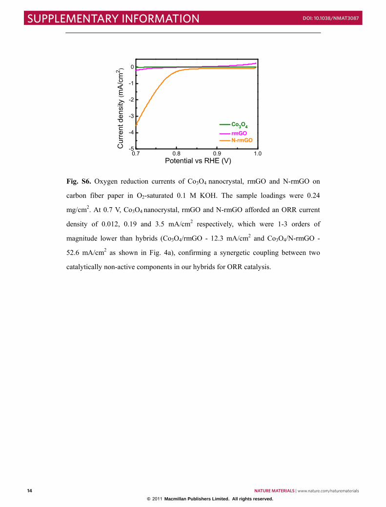
Fig. S6. Oxygen reduction currents of Co3O4 nanocrystal, rmGO and N-rmGO on
carbon fiber paper in O2-saturated 0.1 M KOH. The sample loadings were 0.24
mg/cm2. At 0.7 V, Co3O4 nanocrystal, rmGO and N-rmGO afforded an ORR current
density of 0.012, 0.19 and 3.5 mA/cm2 respectively, which were 1-3 orders of
magnitude lower than hybrids (Co3O4/rmGO - 12.3 mA/cm2 and Co3O4/N-rmGO -
52.6 mA/cm2 as shown in Fig. 4a), confirming a synergetic coupling between two
catalytically non-active components in our hybrids for ORR catalysis.
S15
Fig. S7. (a) Rotating-disk voltammograms of Co3O4/rmGO hybrid and
Co3O4/N-rmGO hybrid (loading 0.1 mg/cm2) in O2-saturated 1�M KOH with a
sweep rate of 5 mV/s and rotation rate of 1600 rpm. (b) Tafel plots of Co3O4/rmGO
and Co3O4/N-rmGO hybrids derived by the mass-transport correction of
corresponding RDE data.
0.4 0.5 0.6 0.7 0.8 0.9 1.0-4
-3
-2
-1
0
Cur
rent
den
sity
(mA
/cm
2 )
Potential (V vs RHE)
Co3O4/N-rmGO Co3O4/rmGO
a b
0.75
0.80
0.85
0.90
0.95
0.1 1 10
b = 40 mV/dec
b = 37 mV/dec
Co3O4/N-rmGO Co3O4/rmGO
Current (mA/cm2)
Pot
entia
l (V
vs
RH
E)
14 NATURE MATERIALS | www.nature.com/naturematerials
SUPPLEMENTARY INFORMATION DOI: 10.1038/NMAT3087

© 2011 Macmillan Publishers Limited. All rights reserved.
S14
0.7 0.8 0.9 1.0-5
-4
-3
-2
-1
0
Cur
rent
den
sity
(mA
/cm
2 )
Potential vs RHE (V)
Co3O4 rmGO N-rmGO
Fig. S6. Oxygen reduction currents of Co3O4 nanocrystal, rmGO and N-rmGO on
carbon fiber paper in O2-saturated 0.1 M KOH. The sample loadings were 0.24
mg/cm2. At 0.7 V, Co3O4 nanocrystal, rmGO and N-rmGO afforded an ORR current
density of 0.012, 0.19 and 3.5 mA/cm2 respectively, which were 1-3 orders of
magnitude lower than hybrids (Co3O4/rmGO - 12.3 mA/cm2 and Co3O4/N-rmGO -
52.6 mA/cm2 as shown in Fig. 4a), confirming a synergetic coupling between two
catalytically non-active components in our hybrids for ORR catalysis.
S15
Fig. S7. (a) Rotating-disk voltammograms of Co3O4/rmGO hybrid and
Co3O4/N-rmGO hybrid (loading 0.1 mg/cm2) in O2-saturated 1�M KOH with a
sweep rate of 5 mV/s and rotation rate of 1600 rpm. (b) Tafel plots of Co3O4/rmGO
and Co3O4/N-rmGO hybrids derived by the mass-transport correction of
corresponding RDE data.
0.4 0.5 0.6 0.7 0.8 0.9 1.0-4
-3
-2
-1
0
Cur
rent
den
sity
(mA
/cm
2 )
Potential (V vs RHE)
Co3O4/N-rmGO Co3O4/rmGO
a b
0.75
0.80
0.85
0.90
0.95
0.1 1 10
b = 40 mV/dec
b = 37 mV/dec
Co3O4/N-rmGO Co3O4/rmGO
Current (mA/cm2)
Pot
entia
l (V
vs
RH
E)
NATURE MATERIALS | www.nature.com/naturematerials 15
SUPPLEMENTARY INFORMATIONDOI: 10.1038/NMAT3087

© 2011 Macmillan Publishers Limited. All rights reserved.
S16
Fig. S8. ORR performance and stability of catalysts. (a) Oxygen reduction
polarization curves of Co3O4/N-rmGO, Pt/C-20% (20 wt% Pt on Vulcan XC-72, Fuel
Cell Store), Pt/C-50% (50 wt% Pt on Vulcan XC-72, Fuel Cell Store), Fe-N/C
(Prepared followed Ref. [3] method) and Pd/C-10% (Palladium, 10% on activated
carbon powder, Alfa Aesar) catalysts (catalyst loading ~0.24 mg/cm2 for all samples)
dispersed on carbon fiber paper (CFP) in O2-saturated 1 M KOH electrolyte. (b)
Chronoamperometric responses (percentage of current retained vs. operation time) of
Co3O4/N-rmGO, Pt/C-20%, Pt/C-50%, Fe-N/C and Pd/C-10% on carbon fiber paper
electrodes kept at 0.70 V vs. RHE in O2-saturated 1M KOH electrolytes respectively.
Co3O4/N-rmGO hybrid showed comparable ORR catalytic activity to Pt/C and
superior stability in alkaline solutions.
0.7 0.8 0.9 1.0
-120
-100
-80
-60
-40
-20
0
Cur
rent
den
sity
(mA
/cm
2 )
Potential (V vs RHE)
Co3O4/N-rmGO Pt/C - 20% Pt/C - 50% Fe-N/C Pd/C - 10%
a b
0 5000 100000
20
40
60
80
100
Co3O4/N-rmGO Pt/C - 20% Pt/C - 50% Fe-N/C Pd/C - 10%N
orm
aliz
ed C
urre
nt (%
)
Time (s)
S17
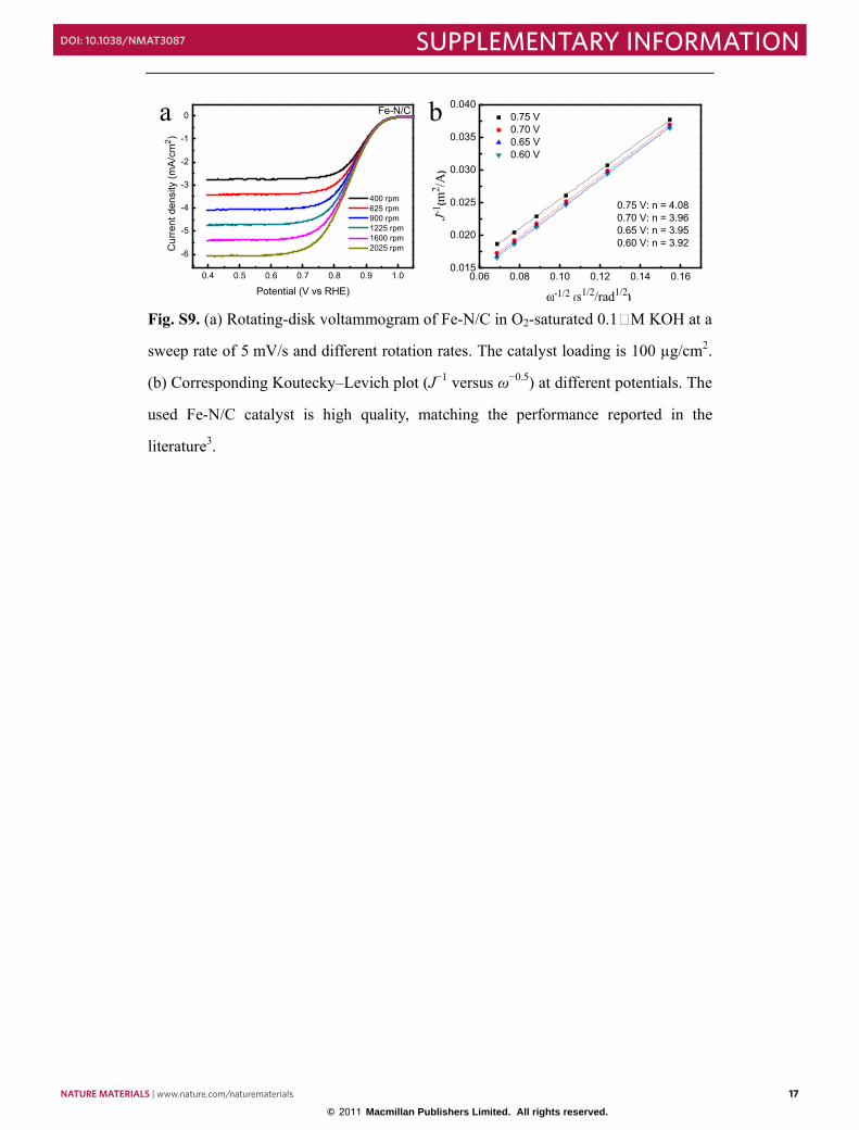
Fig. S9. (a) Rotating-disk voltammogram of Fe-N/C in O2-saturated 0.1�M KOH at a
sweep rate of 5 mV/s and different rotation rates. The catalyst loading is 100 µg/cm2.
(b) Corresponding Koutecky–Levich plot (J−1 versus ω−0.5) at different potentials. The
used Fe-N/C catalyst is high quality, matching the performance reported in the
literature3.
0.06 0.08 0.10 0.12 0.14 0.160.015
0.020
0.025
0.030
0.035
0.040
0.75 V: n = 4.080.70 V: n = 3.960.65 V: n = 3.950.60 V: n = 3.92
0.75 V 0.70 V 0.65 V 0.60 V
J-1(m
2 /A)
ω-1/2 (s1/2/rad1/2) 0.4 0.5 0.6 0.7 0.8 0.9 1.0
-6
-5
-4
-3
-2
-1
0 Fe-N/C
Cur
rent
den
sity
(mA/
cm2 )
Potential (V vs RHE)
400 rpm 625 rpm 900 rpm 1225 rpm 1600 rpm 2025 rpm
a b
16 NATURE MATERIALS | www.nature.com/naturematerials
SUPPLEMENTARY INFORMATION DOI: 10.1038/NMAT3087
© 2011 Macmillan Publishers Limited. All rights reserved.
S16
Fig. S8. ORR performance and stability of catalysts. (a) Oxygen reduction
polarization curves of Co3O4/N-rmGO, Pt/C-20% (20 wt% Pt on Vulcan XC-72, Fuel
Cell Store), Pt/C-50% (50 wt% Pt on Vulcan XC-72, Fuel Cell Store), Fe-N/C
(Prepared followed Ref. [3] method) and Pd/C-10% (Palladium, 10% on activated
carbon powder, Alfa Aesar) catalysts (catalyst loading ~0.24 mg/cm2 for all samples)
dispersed on carbon fiber paper (CFP) in O2-saturated 1 M KOH electrolyte. (b)
Chronoamperometric responses (percentage of current retained vs. operation time) of
Co3O4/N-rmGO, Pt/C-20%, Pt/C-50%, Fe-N/C and Pd/C-10% on carbon fiber paper
electrodes kept at 0.70 V vs. RHE in O2-saturated 1M KOH electrolytes respectively.
Co3O4/N-rmGO hybrid showed comparable ORR catalytic activity to Pt/C and
superior stability in alkaline solutions.
0.7 0.8 0.9 1.0
-120
-100
-80
-60
-40
-20
0
Cur
rent
den
sity
(mA
/cm
2 )
Potential (V vs RHE)
Co3O4/N-rmGO Pt/C - 20% Pt/C - 50% Fe-N/C Pd/C - 10%
a b
0 5000 100000
20
40
60
80
100
Co3O4/N-rmGO Pt/C - 20% Pt/C - 50% Fe-N/C Pd/C - 10%N
orm
aliz
ed C
urre
nt (%
)
Time (s)
S17
Fig. S9. (a) Rotating-disk voltammogram of Fe-N/C in O2-saturated 0.1�M KOH at a
sweep rate of 5 mV/s and different rotation rates. The catalyst loading is 100 µg/cm2.
(b) Corresponding Koutecky–Levich plot (J−1 versus ω−0.5) at different potentials. The
used Fe-N/C catalyst is high quality, matching the performance reported in the
literature3.
0.06 0.08 0.10 0.12 0.14 0.160.015
0.020
0.025
0.030
0.035
0.040
0.75 V: n = 4.080.70 V: n = 3.960.65 V: n = 3.950.60 V: n = 3.92
0.75 V 0.70 V 0.65 V 0.60 V
J-1(m
2 /A)
ω-1/2 (s1/2/rad1/2) 0.4 0.5 0.6 0.7 0.8 0.9 1.0
-6
-5
-4
-3
-2
-1
0 Fe-N/C
Cur
rent
den
sity
(mA/
cm2 )
Potential (V vs RHE)
400 rpm 625 rpm 900 rpm 1225 rpm 1600 rpm 2025 rpm
a b
NATURE MATERIALS | www.nature.com/naturematerials 17
SUPPLEMENTARY INFORMATIONDOI: 10.1038/NMAT3087

© 2011 Macmillan Publishers Limited. All rights reserved.
S18
775 780 785 790 795 800
Abs
orpt
ion
(a.u
.)
Co3O4/N-rmGO
Co3O4
Photon Energy (eV)
Co L-edge
Fig. S10. Co L-edge XANES of Co3O4 nanocrystal and Co3O4/N-rmGO hybrid. The
increase in the normalized peak area in hybrid compared to Co3O4 nanocrystal
indicates increase of unoccupied Co 3d projected state in hybrid, suggesting lower
electron density of Co site in hybrid.
S19
0.6 0.7 0.8 0.9 1.0-120
-100
-80
-60
-40
-20
0
Cur
rent
den
sity
(mA
/cm
2 )
Potential vs RHE (V)
20 at% Co 10 at% Co 3 at% Co
Fig. S11. Oxygen reduction currents of Co3O4/N-rmGO hybrids with various Co
contents dispersed on carbon fiber paper in O2-saturated 0.1 M KOH. The sample
loading was 0.24 mg/cm2. Lowering Co loading from 20 at% to 3-10 at% led to
systematic reduction in ORR activity, suggesting that the active reaction sites in
hybrid materials could be Co oxide species interfaced with GO.
18 NATURE MATERIALS | www.nature.com/naturematerials
SUPPLEMENTARY INFORMATION DOI: 10.1038/NMAT3087

© 2011 Macmillan Publishers Limited. All rights reserved.
S18
775 780 785 790 795 800
Abs
orpt
ion
(a.u
.)
Co3O4/N-rmGO
Co3O4
Photon Energy (eV)
Co L-edge
Fig. S10. Co L-edge XANES of Co3O4 nanocrystal and Co3O4/N-rmGO hybrid. The
increase in the normalized peak area in hybrid compared to Co3O4 nanocrystal
indicates increase of unoccupied Co 3d projected state in hybrid, suggesting lower
electron density of Co site in hybrid.
S19
0.6 0.7 0.8 0.9 1.0-120
-100
-80
-60
-40
-20
0
Cur
rent
den
sity
(mA
/cm
2 )
Potential vs RHE (V)
20 at% Co 10 at% Co 3 at% Co
Fig. S11. Oxygen reduction currents of Co3O4/N-rmGO hybrids with various Co
contents dispersed on carbon fiber paper in O2-saturated 0.1 M KOH. The sample
loading was 0.24 mg/cm2. Lowering Co loading from 20 at% to 3-10 at% led to
systematic reduction in ORR activity, suggesting that the active reaction sites in
hybrid materials could be Co oxide species interfaced with GO.
NATURE MATERIALS | www.nature.com/naturematerials 19
SUPPLEMENTARY INFORMATIONDOI: 10.1038/NMAT3087

© 2011 Macmillan Publishers Limited. All rights reserved.
S20
Fig. S12. Oxygen reduction currents of hybrids versus mixtures dispersed on carbon
fiber paper in O2-saturated 0.1 M KOH. The sample loading was 0.24 mg/cm2. Both
rmGO and N-rmGO hybrids showed much high activity compared to corresponding
physical mixtures, confirming the importance of intimate interaction in the hybrid
materials for ORR performance.
0.7 0.8 0.9 1.0-60
-40
-20
0
Cur
rent
Den
sity
(mA
/cm
2 )
Potential (V vs RHE)
Co3O4/N-rmGO Co3O4 + N-rmGO mixture
0.7 0.8 0.9 1.0
-12
-8
-4
0
Cur
rent
Den
sity
(mA
/cm
2 )
Potential (V vs RHE)
Co3O4/rmGO Co3O4 + rmGO mixture
a b
S21
Fig. S13. ORR performance of Co3O4 hybrid catalysts with different carbon materials
dispersed on carbon fiber paper in O2-saturated 0.1 M KOH electrolyte (catalyst
loading ~0.24 mg/cm2 for all samples). The nitrogen doped hybrid prepared from
Hummer’s GO (GOH) showed lower activity than Co3O4/N-rmGO hybrid, which
could be due to the lower conductivity of GOH. Carbon black hybrid (composite) also
showed much lower activity, likely due to the lack of functional groups in carbon
black as anchored sites of the nanoparticles. These results indicated the high
conductivity and surface area, as well as suitable anchoring sites of mGO are
important for the high activity of the synthesized hybrid materials.
0.7 0.8 0.9 1.0-60
-40
-20
0
Cur
rent
Den
sity
(mA
/cm
2 )
Potential (V vs RHE)
Co3O4/N-rmGO Co3O4/carbon black Co3O4/GOH
20 NATURE MATERIALS | www.nature.com/naturematerials
SUPPLEMENTARY INFORMATION DOI: 10.1038/NMAT3087

© 2011 Macmillan Publishers Limited. All rights reserved.
S20
Fig. S12. Oxygen reduction currents of hybrids versus mixtures dispersed on carbon
fiber paper in O2-saturated 0.1 M KOH. The sample loading was 0.24 mg/cm2. Both
rmGO and N-rmGO hybrids showed much high activity compared to corresponding
physical mixtures, confirming the importance of intimate interaction in the hybrid
materials for ORR performance.
0.7 0.8 0.9 1.0-60
-40
-20
0
Cur
rent
Den
sity
(mA
/cm
2 )
Potential (V vs RHE)
Co3O4/N-rmGO Co3O4 + N-rmGO mixture
0.7 0.8 0.9 1.0
-12
-8
-4
0
Cur
rent
Den
sity
(mA
/cm
2 )
Potential (V vs RHE)
Co3O4/rmGO Co3O4 + rmGO mixture
a b
S21
Fig. S13. ORR performance of Co3O4 hybrid catalysts with different carbon materials
dispersed on carbon fiber paper in O2-saturated 0.1 M KOH electrolyte (catalyst
loading ~0.24 mg/cm2 for all samples). The nitrogen doped hybrid prepared from
Hummer’s GO (GOH) showed lower activity than Co3O4/N-rmGO hybrid, which
could be due to the lower conductivity of GOH. Carbon black hybrid (composite) also
showed much lower activity, likely due to the lack of functional groups in carbon
black as anchored sites of the nanoparticles. These results indicated the high
conductivity and surface area, as well as suitable anchoring sites of mGO are
important for the high activity of the synthesized hybrid materials.
0.7 0.8 0.9 1.0-60
-40
-20
0
Cur
rent
Den
sity
(mA
/cm
2 )
Potential (V vs RHE)
Co3O4/N-rmGO Co3O4/carbon black Co3O4/GOH
NATURE MATERIALS | www.nature.com/naturematerials 21
SUPPLEMENTARY INFORMATIONDOI: 10.1038/NMAT3087

© 2011 Macmillan Publishers Limited. All rights reserved.
S22
Fig. S14. OER stability test of Co3O4/N-rmGO, Co3O4/rmGO and Co3O4 catalysts
dispersed on glassy carbon electrode (with 15% of Nafion as binder) in 1M KOH
electrolyte (catalyst loading 0.10 mg/cm2 for all samples). Cycles were swept between
1.25 V and 1.65 V at 0.2 V/s. The anodic sweeps showed in the figures were measured
from 1.25 V to 1.65 V at 0.005 V/s with IR compensation. All three catalysts suffered
certain current decrease in the beginning cycles (about 20-30% at 1.65 V), which is
mainly due to the blockage of some active sites by the gradual accumulation of
evolved O2 bubbles. The OER current did not decrease significantly after 1000 cycles
in all three catalysts, suggesting the Co3O4/N-rmGO and Co3O4/rmGO hybrid
catalysts are inherently stable for OER.
1.3 1.4 1.5 1.6 1.70
10
20
30
40
50Co3O4/N-rmGO
Cur
rent
den
sity
(mA
/cm
2 )
Potential (V vs RHE)
initial 500 cycle 1000 cycle 1500 cycle
1.3 1.4 1.5 1.6 1.7
0
10
20
30
40Co3O4/rmGO
Cur
rent
den
sity
(mA
/cm
2 )
Potential (V vs RHE)
initial 500 cycle 1000 cycle 1500 cycle
1.3 1.4 1.5 1.6 1.70
10
20
Cur
rent
den
sity
(mA
/cm
2 )
Potential (V vs RHE)
initial 500 cycle 1000 cycle 1500 cycle
Co3O4
a b
c
S23
References
1. Bard, A. J. & Faulkner, L. R. Electrochemical Methods: Fundamentals and
Aplications. (Wiley, 2001).
2. Paulus, U. A., Schmidt, T. J., Gasteiger, H. A. & Behm, R. J. Oxygen reduction on a
high-surface area Pt/Vulcan carbon catalyst: a thin-film rotating ring-disk electrode
study. J. Electroanal. Chem. 495, 134-145 (2001).
3. Meng, H., Jaouen, F., Proietti, E., Lefevre, M. & Dodelet, J. P. pH-effect on oxygen
reduction activity of Fe-based electro-catalysts. Electrochem. Commun. 11,
1986-1989 (2009).
22 NATURE MATERIALS | www.nature.com/naturematerials
SUPPLEMENTARY INFORMATION DOI: 10.1038/NMAT3087

© 2011 Macmillan Publishers Limited. All rights reserved.
S22
Fig. S14. OER stability test of Co3O4/N-rmGO, Co3O4/rmGO and Co3O4 catalysts
dispersed on glassy carbon electrode (with 15% of Nafion as binder) in 1M KOH
electrolyte (catalyst loading 0.10 mg/cm2 for all samples). Cycles were swept between
1.25 V and 1.65 V at 0.2 V/s. The anodic sweeps showed in the figures were measured
from 1.25 V to 1.65 V at 0.005 V/s with IR compensation. All three catalysts suffered
certain current decrease in the beginning cycles (about 20-30% at 1.65 V), which is
mainly due to the blockage of some active sites by the gradual accumulation of
evolved O2 bubbles. The OER current did not decrease significantly after 1000 cycles
in all three catalysts, suggesting the Co3O4/N-rmGO and Co3O4/rmGO hybrid
catalysts are inherently stable for OER.
1.3 1.4 1.5 1.6 1.70
10
20
30
40
50Co3O4/N-rmGO
Cur
rent
den
sity
(mA
/cm
2 )
Potential (V vs RHE)
initial 500 cycle 1000 cycle 1500 cycle
1.3 1.4 1.5 1.6 1.7
0
10
20
30
40Co3O4/rmGO
Cur
rent
den
sity
(mA
/cm
2 )
Potential (V vs RHE)
initial 500 cycle 1000 cycle 1500 cycle
1.3 1.4 1.5 1.6 1.70
10
20
Cur
rent
den
sity
(mA
/cm
2 )
Potential (V vs RHE)
initial 500 cycle 1000 cycle 1500 cycle
Co3O4
a b
c
S23
References
1. Bard, A. J. & Faulkner, L. R. Electrochemical Methods: Fundamentals and
Aplications. (Wiley, 2001).
2. Paulus, U. A., Schmidt, T. J., Gasteiger, H. A. & Behm, R. J. Oxygen reduction on a
high-surface area Pt/Vulcan carbon catalyst: a thin-film rotating ring-disk electrode
study. J. Electroanal. Chem. 495, 134-145 (2001).
3. Meng, H., Jaouen, F., Proietti, E., Lefevre, M. & Dodelet, J. P. pH-effect on oxygen
reduction activity of Fe-based electro-catalysts. Electrochem. Commun. 11,
1986-1989 (2009).
NATURE MATERIALS | www.nature.com/naturematerials 23
SUPPLEMENTARY INFORMATIONDOI: 10.1038/NMAT3087