Embed Size (px)
Citation preview

DocuPrint CM205b / CP205w / CP205 / CP105b
Service Manual 1st Edition
Draft


• This service manual covers the following models FUJI XEROX Co. Ltd. Color Laser PrinterDocuPrint CM205b / CP205w / CP205 / CP 105b
• Related MaterialsNo other related materials issued other than this service manual.
• Confidentiality• This service manual is issued intending use by
maintenance service personnel authorized by FUJI XEROX Co. Ltd. Copying, transferring or leasing this manual without prior consent by FUJI XEROX Co. Ltd. is prohibited.
• When a page becomes irrelavant (e.g. superceded by a replacement page)
• Handle with care to avoid loss or damage of the manual.
• Revision and Modification InformationWhen design changes or revisions relating to this service manual occur, the overseas technical information or overseas service bulletin may be issued as supplementary information until such changes are accomodated in the updated version of this service manual.
CAUTION Important changes including revisions of spare part numbers and adjustment specifications must immediately be reflected on the respective pages of this service manual upon reception of such information.
Edited by: Fuji Xerox Co., Ltd. CS/TSMinatoMirai Center Bldg. 7F3-6-1 Minatomirai Nishi-ku, Yokohama, Kanagawa 220-0012, JAPANTEL: 045-414-5725
[XEROX] is registered trademark.
PRINTED IN JAPAN
DocuPrint CM205 b / CP205w / CP205 / CP 105bService Manual 1st Edition Issued: February 2011

Company Name
Department Name
Telephone No.
Full Name Employee No.

PrefaceGetting to know the Service ManualHow to use the Service ManualTerms and SymbolsAbbreviations
Chapter 1 Service Call Procedure (Not yet issued)
Chapter 2 Troubleshooting
Chapter 3 Image Quality Troubleshooting (Not yet issued)
Chapter 4 Disassembly / Assembly and Adjustments
Chapter 5 Parts List
Chapter 6 General (Not yet issued)
Chapter 7 Wiring Data (Not yet issued)
Chapter 8 Accessories (Not yet issued)
Chapter 9 Installation (Not yet issued)
Chapter 10 Machine Overview


Preface

PrefaceTable of Contents
Table of Contents1 Getting to know the Service Manual .............................................................. Preface-12 How to use the Service Manual ..................................................................... Preface-1
2.1 Contents of Manual ......................................................................................................Preface-12.2 Information on Updating ...............................................................................................Preface-2
3 Terms and Symbols ....................................................................................... Preface-34 Abbreviations ................................................................................................. Preface-4

Introduction1. Getting to know the Service Manual
Preface-1
1. Getting to know the Service ManualThis manual is used as the standard service manual for the DocuPrint CM205b / CP205w / CP205 /CP105b.
• Publication Comment SheetEnter any comments and/or corrections regarding the DocuPrint CM205b / CP205w / CP205 / CP105b service manual into the Publication Comment Sheet, and send it to FX/TS/OSG through the OpCo TS or CS department.
2. How to use the Service ManualThis manual describes the standard procedures for the servicing of the DocuPrint CM205b / CP205w / CP205 / CP105b.
2.1 Contents of Manual• Hardware
This manual summarizes all technical information on the DocuPrint CM205b / CP205w / CP205 /CP105b.
• ChaptersThis manual is divided into ten chapters as described below.
Chapter 1 Service Call ProcedureNot yet issued.
Chapter 2 TroubleshootingThis chapter describes the troubleshooting procedures other than image quality troubleshooting of the DocuPrint CM205b / CP205w / CP205 / CP105b. It also describes how to use the diagnostics and some programs.
Chapter 3 Image Quality TroubleshootingNot yet issued.
Chapter 4 Disassembly / Assembly and AdjustmentsThis chapter describes the disassembly, assembly, adjustment and replacement procedures for components of the DocuPrint CM205b / CP205w / CP205 / CP105b.
Chapter 5 Parts ListThis chapter contains spare parts list for DocuPrint CM205b / CP205w / CP205 / CP105b.
Chapter 6 General
Not yet issued.
Chapter 7 Wiring DataNot yet issued.
Chapter 8 AccessoriesNot yet issued.
Chapter 9 InstallationNot yet issued.
Chapter 10 Machine OverviewThis chapter gives an overview of the functions of the main components of DocuPrintCM205b / CP205w / CP205 / CP105b.
Introduction2. How to use the Service Manual
Preface-2
2.2 Information on UpdatingThis manual will be revised and sent to each customer engineer as specified below. Revisions must be incorporated correctly to keep the manual up-to-date.
Updating Procedure• When the entire manual is revised, "1st Edition" on the front cover will be renewed to 1st Edition,
2nd Edition, 3rd Edition and so on.• When this manual is partially revised, revisions will be sequentially indicated as Revision A,
Revision B, Revision C, etc. All revised pages will be marked accordingly with "Revision A", "Revision B", "Revision C" and so on.
Revision Sidebar When any paragraph, table or figure has been added or amended, a revision sidebar will be added to indicate where the revision was made.
If the same page is changed again due to a subsequent revision, revision sidebars associated with the previous revision(s) will be deleted.
(Example)

Introduction3. Terms and Symbols
Preface-3
3. Terms and SymbolsSpecific terms and symbols used in any particular chapter are described in the Preface for thatsection. The terms and symbols described here are used throughout this manual.
• The terms and symbols used at the beginning of a text are defined as follows:
DANGER Indicates an imminently hazardous situation, such as death or serious injury if operators do not handle the machine correctly by disregarding the statement.
WARNING Indicates a potentially hazardous situation, such as death or serious injury if operators do not handle the machine correctly by disregarding the statement.
CAUTION Indicates a potentially hazardous situation, such as injury or property damage if operators do not handle the machine correctly by disregarding the statement.
INSTRUCTION Indicates that the printer or its components may be damaged if the instructed procedure is not strictly observed.
NOTE Used to emphasize the procedure, servicing, and regulation.
REFERENCE Used to describe the technical terminology and supplementary explanations.
OBJECTIVE Used to explain purpose of adjustment.• REP : Indicates the disassembly/assembly procedure for reference.• ADJ : Indicates the adjustment procedure for reference.• PL : Indicates the parts list for reference.• ASSY : Means Assembly.
Safety Critical Components (SCC)Control of the safety of components that are designated Safety Critical Components shall conform to Fuji Xerox Co. Ltd-stipulated rules and regulations on Safety Critical Components.As to replacement of any component designated SCC, the complete component unit must be replaced. It must never be disassembled or no individual internal parts of it must be replaced.Installation of any part other than the ones designated by Fuji Xerox Co. Ltd. shall be strictly prohibited because it cannot be guaranteed in quality and safety.
Important Information Stored Component (ISC)Important Information Stored Components store customers’ important information they have entered after machine installation. When replacing Important Information Stored Components, you must replace and discard them, following the procedure described in Chapter 4 Adjustments. Take care never to let customer information leak out.

Introduction4. Abbreviations
Preface-4
4. AbbreviationsAbbreviationsThis manual contains abbreviations that are specific to this manual, as well as general abbreviations, which include:
ADC Automatic Density ControlAG Analog GroundAPS Auto Paper SelectARC Auto Registration ControlASSY AssemblyATS Auto Tray SwitchingB BlackBCR Bias Charge RollBk BlackBLK BlackBLU BlueBRN BrownBTR Bias Transfer RollC CyanCLN CleanerCRU Customer Replaceable UnitCRUM CRU MonitorCTRG CartridgeDET Detoner RollDEVE. DeveloperDIAG. DiagnosticDISP Dispensedpi dots per inchDTS Detack SawDUP DuplexESB Electro Static BrushESS Electric SubsystemF FrontFEED, FDR FeederFIP Fault Isolation ProcedureGND GroundGRN GreenGRY GrayHT Half ToneHUM HumidityHVPS High Voltage Power SupplyICDC Image Count Dispense Control ID Image Density, or
IdentificationIBT Intermediate Belt TransferINTL, INLK InterlockIOT Image Output TerminalK BlackL LeftL/H Left HandLD Laser diodeLDD Lightly Doped DrainLED Light-emitting diodeLEF Long Edge FeedLH Left HandLV Low VoltageLVPS Low Voltage Power SupplyM Magenta
MAG Mag. RollMCU Machine Control UnitMOB Marks On BeltMOT MotorMSI Multi Sheet InserterN/P No PaperNVM Non Volatile MemoryOEM Original Equipment
ManufacuringOHP Overhead ProjectOP OperationOPC Organic Photo ConductorORN ORANGEPC Personal ComputerPCDC Pixel Count Dispense ControlPH Paper HandlingPHD Printer HeadPNK PinkPOP Paper On PhotoreceptorPPM Prints Per MinutePR,P/R ProcessPV Print VolumePWB(A) Printed Wiring Boad
(Assembly)R RightR RearR/H Right HandREF RefresherREGI. RegistrationRH Right HandROS Raster Output ScannerROT RotaryRTC Rubber Tube ChargerRTN ReturnSEF Short Edge FeedSG Signal GroundSMH Special Material HandlerSNR SensorSOL. SolenoidSOS Start Of ScanSTM Single Tray ModuleSW SwitchTEMP. TemperatureTM Tray ModuleTNER, TNR TonerTP ThermopileTR TransferVIO VioletWHT WhiteXERO XerographicY YellowYEL Yellow

Chapter 2 Troubleshooting


Contents
2.1 Status Codes [DocuPrint CM205b]............................................................................2-12.1.1 Controller ........................................................................................................................................ 2-1
2.1.2 IOT .................................................................................................................................................. 2-2
2.1.3 Scanner........................................................................................................................................... 2-5
2.2 Status Codes
[DocuPrint CP205w/CP205/CP105b] ..............................................................................2-12


Chapter 2 Troubleshooting2.1 Status Codes [DocuPrint CM205b]
2.1 Status Codes [DocuPrint CM205b]
2.1.1 Controller
Status Code
Error Summary/Description Solution
016-315 Quick DRAM check failure Replace ESS PWB. (REP8)
016-317 CODEROM content invalid Replace ESS PWB. (REP8)
016-501 Can not update application code in FLASH Replace ESS PWB. (REP8)
016-502 Can not update parameters correctly in FLASH Replace ESS PWB. (REP8)
016-718Out of MemoryMemory is insufficient.
Wait until the other job releases memory and the system becomes idle, and then retry.
016-719 Decode error No action required.
016-720PDL ErrorAn invalid command/data has been detected.
No action required.
016-744Firmware Download Format ErrorAn invalid code has been downloaded.
Download the correct firmware.
016-745Firmware Download Format ErrorAn invalid data has been downloaded.
Download the correct firmware.
016-749PJL ErrorA PJL format error has been detected.
No action required.
016-791 USB Memory was removed Insert the USB memory.
016-795File Format ErrorA JPEG/TIFF/PDF header check error has occurred.
Select a supported file.
016-797 File Read ErrorSelect a file that can be read successfully.
016-920 AP detecting fail while WPS setup. Replace ESS PWB. (REP8)
018-338 Configuration to WIFI dongle is failed. Replace ESS PWB. (REP8)
024-360 MCU firmware AP code is failed. Replace IOT ASSY.
024-371 Controller board failed to communicate with IOT engine Replace IOT ASSY.
024-958The selected paper size is not available in the printerThe actual paper size in tray is different from the specified paper size.
Replace IOT ASSY.
024-963Paper is not loaded in the selected tray.The specified paper size is not available on the actual machine. (or MPF [PSI] is empty)
Replace IOT ASSY.
027-446IPV6 address duplicateAt startup, duplicated IPv6 addresses were detected on the network.
Replace ESS PWB. (REP8)
027-452IPV4 address duplicateAt startup, duplicated IPv4 addresses were detected on the network.
Replace ESS PWB. (REP8)
062-360 Obama chip initialization failed Replace ESS PWB. (REP8)
2-1

Chapter 2 Troubleshooting2.1 Status Codes [DocuPrint CM205b]
2.1.2 IOT
075-921Press the Set buttonThe printer is waiting for the <OK> button to be pressed after Side 2 for manual duplex print was set.
Press the <OK> button.
116-210 USBH port failed Replace ESS PWB. (REP8)
116-314Cannot get MAC address / WIFI MAC address when initialization
Replace ESS PWB. (REP8)
116-323NVRAM R/W Check FailAn error has been detected in the NVRAM Read/Write check.
Replace ESS PWB. (REP8)
116-325NVRAM R/W Check FailAn error has been detected in the NVRAM Read/Write check.
Replace ESS PWB. (REP8)
116-326NVRAM R/W Check FailAn error has been detected in the NVRAM Read/Write check.
Replace ESS PWB. (REP8)
116-335 Check sum is not right when NVRAM initialization Replace ESS PWB. (REP8)
116-355Network Fatal ErrorA fatal error has occurred in the network application.
Replace ESS PWB. (REP8)
116-395 USBD port failed Replace ESS PWB. (REP8)
117-331 ESS related error Replace ESS PWB. (REP8)
117-332 ESS related error Replace ESS PWB. (REP8)
117-333 ESS related error Replace ESS PWB. (REP8)
117-334 ESS related error Replace ESS PWB. (REP8)
117-349 ESS related error Replace ESS PWB. (REP8)
117-350 ESS related error Replace ESS PWB. (REP8)
117-351 ESS related error Replace ESS PWB. (REP8)
117-366 ESS related error Replace ESS PWB. (REP8)
134-211 Controller board failed to communicate with FAX module Replace ESS PWB. (REP8)
Status Code
Description Solution
009 950<Y Toner Comm Fail>A communication error regarding Toner CRUM (Y) has been detected.
Replace IOT ASSY.
009 951<M Toner Comm Fail>A communication error regarding Toner CRUM (M) has been detected.
Replace IOT ASSY.
009 952<C Toner Comm Fail>A communication error regarding Toner CRUM (C) has been detected.
Replace IOT ASSY.
Status Code
Error Summary/Description Solution
2-2

Chapter 2 Troubleshooting2.1 Status Codes [DocuPrint CM205b]
009 953<K Toner Comm Fail>A communication error regarding Toner CRUM (K) has been detected.
Replace IOT ASSY.
010 397<Fuser Failure>An operation error of the fusing unit (abnormal temperature, etc.) has occurred.
Replace IOT ASSY.
024 340<Firmware Error>An MCU firmware error has been detected.
Replace IOT ASSY.
041 340<NVRAM Error>An NVRAM error has been detected.
Replace IOT ASSY.
042 325<Motor Failure>A Main Motor failure has been detected.
Replace IOT ASSY.
042 358<Fan Motor Failure>A Fan Motor Error has been detected.
Replace IOT ASSY.
042 372<Deve Mode Change Failure>A Deve Mode Change failure has been detected.
Replace IOT ASSY.
061 370<LPH Failure>An LPH failure has been detected.
Replace IOT ASSY.
075 100<Misfeed Jam> (DocuPrint CP205/CP205w)A miss feed jam has been detected on MPF (PSI).
Replace IOT ASSY.
077 100<Paper Remain at Regi (MPF/PSI)>A Reg On early JAM has been detected.A sheet is remaining at the registration section.
Replace IOT ASSY.
077 104
<Reg OFF Jam>A Reg OFF Jam has been detected.The sheet did not pass through the Regi Sensor within the specified time.
Replace IOT ASSY.
077 106
<Exit On JAM>An Exit On JAM has been detected.The sheet did not reach the Exit Sensor within the specified time.
Replace IOT ASSY.
077 108
<Exit Off early JAM>An Exit Off early JAM has been detected.The sheet passed through the Exit Sensor before the specified time elapsed.
Replace IOT ASSY.
077 109
<Exit Off JAM>An Exit Off JAM has been detected.The sheet did not pass through the Exit Sensor before the specified time elapsed.
Replace IOT ASSY.
077 304<Rear Cover Open>The Rear Cover is open.
Replace IOT ASSY.
Status Code
Description Solution
2-3

Chapter 2 Troubleshooting2.1 Status Codes [DocuPrint CM205b]
077 900<Paper Remain at Exit>A jam has been detected at the Exit section.
Replace IOT ASSY.
077 901<Paper Remain at Regi>A jam has been detected at the registration section.
Replace IOT ASSY.
091 402<Xero Near Life>A XERO Life Warning has been detected.
Replace IOT ASSY.
092 310<CTD Sensor Contamination>Contamination of CTD Sensor has been detected.
Replace IOT ASSY.
092 651<CTD sensor error>An IOT CTD Sensor Error has been detected.
Replace IOT ASSY.
092 661<Environment Sensor Error>An Environment Sensor (temperature/humidity sensor) Error has been detected.
Replace IOT ASSY.
092 910<CTD Sensor Contamination Warning>A CTD Sensor Contamination Warning has been detected.
Replace IOT ASSY.
093 423<Toner Cartridge (Y) Near Life>The Toner Cartridge (Y) needs to be replaced soon.
Replace IOT ASSY.
093 424<Toner Cartridge (M) Near Life>The Toner Cartridge (M) needs to be replaced soon.
Replace IOT ASSY.
093 425<Toner Cartridge (C) Near Life>The Toner Cartridge (C) needs to be replaced soon.
Replace IOT ASSY.
093 426<Toner Cartridge (K) Near Life>The Toner Cartridge (K) needs to be replaced soon.
Replace IOT ASSY.
093 919<Y Toner Low Density>Low density has been detected for the yellow toner.
Replace IOT ASSY.
093 920<M Toner Low Density>Low density has been detected for the magenta toner.
Replace IOT ASSY.
093 921<C Toner Low Density>Low density has been detected for the cyan toner.
Replace IOT ASSY.
093 922<K Toner Low Density>Low density has been detected for the black toner.
Replace IOT ASSY.
093 926<K CRUM ID Error>An ID error has been detected on the Toner CRUM (K).
Replace IOT ASSY.
093 930<Toner Cartridge (Y) Life Over>The Toner Cartridge (Y) has reached the replacement time.
Replace IOT ASSY.
Status Code
Description Solution
2-4

Chapter 2 Troubleshooting2.1 Status Codes [DocuPrint CM205b]
2.1.3 Scanner
093 931<Toner Cartridge (M) Life Over>The Toner Cartridge (M) has reached the replacement time.
Replace IOT ASSY.
093 932<Toner Cartridge (C) Life Over>The Toner Cartridge (C) has reached the replacement time.
Replace IOT ASSY.
093 933<Toner Cartridge (K) Life Over>The Toner Cartridge (K) has reached the replacement time.
Replace IOT ASSY.
093 960<Y CRUM ID Error>An ID error has been detected on the Toner CRUM (Y).
Replace IOT ASSY.
093 961<M CRUM ID Error>An ID error has been detected on the Toner CRUM (M).
Replace IOT ASSY.
093 962<C CRUM ID Error>An ID error has been detected on the Toner CRUM (C).
Replace IOT ASSY.
093 970<Toner Cartridge (Y) Detached>The Toner Cartridge (Y) is not fully seated.
Replace IOT ASSY.
093 971<Toner Cartridge (M) Detached>The Toner Cartridge (M) is not fully seated.
Replace IOT ASSY.
093 972<Toner Cartridge (C) Detached>The Toner Cartridge (C) is not fully seated.
Replace IOT ASSY.
093 973<Toner Cartridge (K) Detached>The Toner Cartridge (K) is not fully seated.
Replace IOT ASSY.
124 333<ASIC Failure>An ASIC failure has been detected.
Replace IOT ASSY.
191 310<XERO Life Over>The device (XERO DEVE LPH BELT ASSY) has reached its end of life.
Replace IOT ASSY.
193 700<Custom Toner Mode>The device is in the Custom Toner Mode.
Replace IOT ASSY.
Status Code
Description Solution
005-121ADF JamA jam has occurred on the ADF.
Replace ADF ASSY.
Status Code
Description Solution
2-5

Chapter 2 Troubleshooting2.1 Status Codes [DocuPrint CM205b]
005-301ADF Cover OpenThe ADF Top Cover is open.
Replace ADF ASSY.
016-372 DRAM memory allocation Fail. Replace ESS PWB. (REP8)
016-503 Email Send Sever Name Error1. Check with the system administrator whether the server settings are correct.2. Retry the scan job.
016-504 Email Send POP Authentication Error1. Check with the system administrator whether the authentication settings are correct.2. Retry the scan job.
016-506
Email Send Error because some fields are blank.The server IP address or e-mail recipient address is not specified.
1. Check whether the e-mail server IP address or the e-mail recipient address is correct.2. Retry the scan job.
016-507 Email Send SMTP Authentication Error1. Check with the system administrator whether the authentication settings are correct.2. Retry the scan job.
016-720 PDL Error -
016-749 PJL Error -
016-764Email Send Connect FailedConnection to the mail server cannot be established when e-mail is sent.
1. Check whether the network cables are correctly connected.2. Retry the scan job.
016-766 Email Send Error1. Send a ping to the remote mail sever to check whether it is available.2. Retry the scan job.
016-767 Email Send Invalid Recipient Address1. Check whether the e-mail server is correctly configured.2. Retry the scan job.
016-791USB Memory was removedIt has been detected that the USB memory is not inserted.
1. Check whether the USB memory is correctly inserted.2. Retry the scan job.
016-930 The device is not supported1. Remove any unsupported device.2. Check the content of the message.
016-931 The USB hub is not supported1. Remove any unsupported device.2. Check the content of the message.
016-981 Collate full Load fewer original documents.
016-985 Email Send File Size Limit Error1. Check the scan default settings for e-mail size. Enlarge it to a larger value according to the image size.2. Retry the scan job.
017-970 Out of Memory1. Check the scan default settings for e-mail size. Enlarge it to a larger value according to the image size.2. Retry the scan job.
017-980 Report Error -
017-981 Report Error -
017-988 Scan Timeout Error1. Check whether the USB cable is correctly connected.2. Check whether the host computer is available.
Status Code
Description Solution
2-6

Chapter 2 Troubleshooting2.1 Status Codes [DocuPrint CM205b]
017-990 Can not find Reference mark well Replace IIT ASSY (REP8.2/REP9.2
024-963
Paper is not loaded in the selected tray.The specified paper size is not available on the actual machine. (Only A4 and Letter are supported.)
Load print media of the correct size.
026-720 USB Memory Full1. Check whether the USB memory is filled to capacity.2. Retry the scan job.
026-721 USB Memory Send File Write Error1. Check whether the USB memory is write-protected or has a disk error.2. Retry the scan job.
026-721 USB Memory Send File Write Error1. Check whether the USB memory is write-protected or has a disk error.2. Retry the scan job.
026-722 USB Memory Write Protect1. Check whether the USB memory is write-protected or has a disk error.2. Retry the scan job.
026-723 USB Memory Send File Path Limit1. Check whether the path name/file name is not too long.2. Set a shorter path, and then retry the scan job.
026-750Scan ErrorAn unknown command or protocol has been detected via USB or network.
1. Check whether the USB cable or the network cable is correctly connected.2. On the host computer, exit the scan application and then restart it.3. Retry the scan job.
026-751Scan ErrorDuring data transmission, the connection via USB or network was cut off.
1. Check whether the USB cable or the network cable is correctly connected.2. Retry the scan job.
026-752Scan Connect FailedAn interrupt request cannot be sent to the USB.
1. Check whether the USB cable is correctly connected.
031-521 SMB Login Failed
1. Check with the system administrator whether the access settings to the SMB server are correct.2. Resolve the server problem, and then retry the scan job.
031-526 SMB Name Resolve Error1. Check whether the domain name for the SMB server is correct.2. Retry the scan job.
031-529SMB Send Login FailedA folder ID error has occurred or the password is wrong.
1. Check whether the network connection is established.2. Check whether the password settings for the SMB server are correct.3. Retry the scan job.
031-530 SMB Send Error
1. Check whether the working path settings to the SMB server are correct.2. Resolve the server problem, and then retry the scan job.
Status Code
Description Solution
2-7

Chapter 2 Troubleshooting2.1 Status Codes [DocuPrint CM205b]
031-533SMB Send ErrorFile names cannot be created.
1. Check whether the SMB server has not encountered a problem of file name conflict, write-protection, or disk error.2. Resolve the server problem, and then retry the scan job.
031-534SMB Send ErrorDirectories cannot be created for SMB.
1. Check whether the SMB server has not encountered a problem of write protection or disk error.2. Retry the scan job.
031-535 SMB Send Error
1. Check whether the SMB server has not encountered a problem of write protection or disk error.2. Resolve the server problem, and then retry the scan job.
031-536 SMB Send Error
1. Check whether the SMB server has not encountered a problem of write protection or disk error.2. Resolve the server problem, and then retry the scan job.
031-537SMB Send ErrorThe SMB server is filled to capacity.
1. Check whether the disk of the SMB server is filled to capacity.2. Resolve the server problem, and then retry the scan job.
031-555 SMB Send Connect Failed1. Check whether the network connection is established.2. Retry the scan job.
031-556SMB Send ErrorData cannot be written to SMB.
1. Check whether the SMB server has not encountered a problem of write protection or disk error.2. Resolve the server problem, and then retry the scan job.
031-557 SMB Send Error
1. Check whether the SMB server has not encountered a problem of file name conflict.2. Resolve the server problem, and then retry the scan job.
031-558 SMB Connect Failed
1. Check with the system administrator whether the access settings to the SMB server are correct.2. Resolve the server problem, and then retry the scan job.
031-571 FTP Send Connect Failed1. Check whether the network connection is established.2. Retry the scan job.
031-574 FTP Send Name Resolve Error1. Check whether the domain name for the FTP server is correct.2. Retry the scan job.
031-575 FTP Send Error
1. Check whether the host name settings for the FTP sever is correct.2. Resolve the server problem, and then retry the scan job.
031-576FTP Send Server not FoundThe FTP server cannot be accessed.
1. The FTP server has not encountered a problem of write protection or disk error.2. Retry the scan job.
Status Code
Description Solution
2-8

Chapter 2 Troubleshooting2.1 Status Codes [DocuPrint CM205b]
031-578FTP Send Login FailedAn FTP ID error has occurred or the password is wrong.
1. Check whether the network connection is established.2. Check whether the password settings for the FTP server are correct.3. Retry the scan job.
031-579 FTP Send Error
1. Check whether the working path settings for the FTP server are correct.2. Resolve the server problem, and then retry the scan job.
031-582FTP Send ErrorFile names cannot be created.
1. The FTP server has not encountered a problem of write protection or disk error.2. Resolve the server problem, and then retry the scan job.
031-584FTP Send ErrorDirectories cannot be created for FTP.
1. The FTP server has not encountered a problem of file name conflict, write protection or disk error.2. Resolve the server problem, and then retry the scan job.
031-585 FTP Send Error
1. The FTP server has not encountered a problem of delete/write protection or disk error.2. Resolve the server problem, and then retry the scan job.
031-587 FTP Send Error
1. The FTP server has not encountered a problem of delete/write protection or disk error.2. Resolve the server problem, and then retry the scan job.
031-588FTP Send ErrorData cannot be written to FTP.
1. The FTP server has not encountered a problem of write protection or disk error.2. Resolve the server problem, and then retry the scan job.
031-589FTP Send ErrorThe FTP server is filled to capacity.
1. Check whether the disk of the FTP server is filled to capacity.2. Resolve the server problem, and then retry the scan job.
031-594 FTP Send Error
1. Check with the system administrator whether the settings for the scanned file being transferred to the FTP server are correct.2. Resolve the server problem, and then retry the scan job.
031-598 FTP Send Error
1. The FTP server has not encountered a problem of write protection or disk error.2. Resolve the server problem, and then retry the scan job.
033-503 Fax Memory Full1. Retry the job.2. Check the report.
033-513 Fax Memory Full1. Retry the job.2. Check the report.
033-517 Fax Send Error Retry the job.
033-518 Fax Send Error Retry the job.
033-519 Fax Send Error Retry the job.
Status Code
Description Solution
2-9
Chapter 2 Troubleshooting2.1 Status Codes [DocuPrint CM205b]
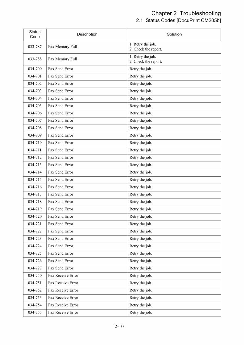
033-787 Fax Memory Full1. Retry the job.2. Check the report.
033-788 Fax Memory Full1. Retry the job.2. Check the report.
034-700 Fax Send Error Retry the job.
034-701 Fax Send Error Retry the job.
034-702 Fax Send Error Retry the job.
034-703 Fax Send Error Retry the job.
034-704 Fax Send Error Retry the job.
034-705 Fax Send Error Retry the job.
034-706 Fax Send Error Retry the job.
034-707 Fax Send Error Retry the job.
034-708 Fax Send Error Retry the job.
034-709 Fax Send Error Retry the job.
034-710 Fax Send Error Retry the job.
034-711 Fax Send Error Retry the job.
034-712 Fax Send Error Retry the job.
034-713 Fax Send Error Retry the job.
034-714 Fax Send Error Retry the job.
034-715 Fax Send Error Retry the job.
034-716 Fax Send Error Retry the job.
034-717 Fax Send Error Retry the job.
034-718 Fax Send Error Retry the job.
034-719 Fax Send Error Retry the job.
034-720 Fax Send Error Retry the job.
034-721 Fax Send Error Retry the job.
034-722 Fax Send Error Retry the job.
034-723 Fax Send Error Retry the job.
034-724 Fax Send Error Retry the job.
034-725 Fax Send Error Retry the job.
034-726 Fax Send Error Retry the job.
034-727 Fax Send Error Retry the job.
034-750 Fax Receive Error Retry the job.
034-751 Fax Receive Error Retry the job.
034-752 Fax Receive Error Retry the job.
034-753 Fax Receive Error Retry the job.
034-754 Fax Receive Error Retry the job.
034-755 Fax Receive Error Retry the job.
Status Code
Description Solution
2-10

Chapter 2 Troubleshooting2.1 Status Codes [DocuPrint CM205b]
034-756 Fax Receive Error Retry the job.
034-757 Fax Receive Error Retry the job.
034-758 Fax Receive Error Retry the job.
034-759 Fax Receive Error Retry the job.
034-760 Fax Receive Error Retry the job.
034-761 Fax Receive Error Retry the job.
034-762 Fax Receive Error Retry the job.
034-763 Fax Receive Error Retry the job.
034-764 Fax Receive Error Retry the job.
034-765 Fax Receive Error Retry the job.
034-766 Fax Receive Error Retry the job.
034-767 Fax Receive Error Retry the job.
034-768 Fax Receive Error Retry the job.
062-321 Carriage Motor Error Replace IIT ASSY (REP4)
062-322Can not get valid calibration result by default algorithm.
Replace IIT ASSY (REP4)
062-790 Scan Error Replace IIT ASSY (REP4)
117-340 SIA encounter DSP emergency error. Replace ESS PWB. (REP8)
117-342 SIA detects CODEC service error Replace ESS PWB. (REP8)
117-343 ESS related error Replace ESS PWB. (REP8)
117-344 ESS related error Replace ESS PWB. (REP8)
117-346 ESS related error Replace ESS PWB. (REP8)
117-348 ESS related error Replace ESS PWB. (REP8)
Status Code
Description Solution
2-11

Chapter 2 Troubleshooting2.2 Status Codes [DocuPrint CP205w/CP205/CP105b]
2.2 Status Codes
[DocuPrint CP205w/CP205/CP105b]
NOTE
DocuPrint CP105b is not equipped with an LCD panel. To check the status, read the LED illumination
pattern on the operation panel or display the status via the servicing software.
Status Code
Description Solution
010 397<Fuser Failure>An operation error of the fusing unit (abnormal temperature, etc.) has occurred.
Replace IOT ASSY.
016 500<Download Delete Error>An error occurred while the flash memory was deleted at download.
Replace ESS PWB (REP7)
016 501<Download Write Error>An error has occurred while the flash memory was written to at download.
Replace ESS PWB (REP7)
016 502<Download Verify Error>An error has occurred while the flash memory was verified at download.
Replace ESS PWB (REP7)
016 718<Memory Over flow>Memory is insufficient.
Replace ESS PWB (REP7)
016 720<PDL Error>An error occurred within the decomposer.
Replace ESS PWB (REP7)
016 737<Download Format Error>The format of the downloaded file is invalid.
Replace ESS PWB (REP7)
016 741<Download Protect Error>An error has occurred when an attempt was made to write to the BOOT area at download.
Replace ESS PWB (REP7)
016 742<Download ID Error>The file ID of the downloaded file is invalid.
Replace ESS PWB (REP7)
016 743<Download Range Error>The write destination address at download is invalid. A range check error has occurred.
Replace ESS PWB (REP7)
016 744<Download Check Sum Error>The checksum of the downloaded file is invalid.
Replace ESS PWB (REP7)
016 745<Download header Error>The header information of the downloaded file is invalid.
Replace ESS PWB (REP7)
016 799<Job Environment Violation>The configuration of the printer on the printer driver does not conform to the printer.
Replace ESS PWB (REP7)
2-12
Chapter 2 Troubleshooting2.2 Status Codes [DocuPrint CP205w/CP205/CP105b]
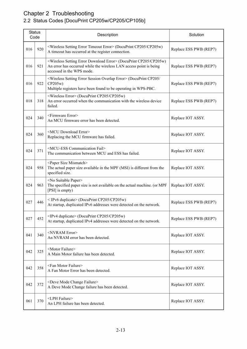
016 920<Wireless Setting Error Timeout Error> (DocuPrint CP205/CP205w)A timeout has occurred at the register connection.
Replace ESS PWB (REP7)
016 921<Wireless Setting Error Download Error> (DocuPrint CP205/CP205w)An error has occurred while the wireless LAN access point is being accessed in the WPS mode.
Replace ESS PWB (REP7)
016 922<Wireless Setting Error Session Overlap Error> (DocuPrint CP205/CP205w)Multiple registers have been found to be operating in WPS-PBC.
Replace ESS PWB (REP7)
018 318<Wireless Error> (DocuPrint CP205/CP205w)An error occurred when the communication with the wireless device failed.
Replace ESS PWB (REP7)
024 340<Firmware Error>An MCU firmware error has been detected.
Replace IOT ASSY.
024 360<MCU Download Error>Replacing the MCU firmware has failed.
Replace IOT ASSY.
024 371<MCU-ESS Communication Fail>The communication between MCU and ESS has failed.
Replace IOT ASSY.
024 958<Paper Size Mismatch>The actual paper size available in the MPF (MSI) is different from the specified size.
Replace IOT ASSY.
024 963<No Suitable Paper>The specified paper size is not available on the actual machine. (or MPF [PSI] is empty)
Replace IOT ASSY.
027 446< IPv6 duplicate> (DocuPrint CP205/CP205w)At startup, duplicated IPv6 addresses were detected on the network.
Replace ESS PWB (REP7)
027 452<IPv4 duplicate> (DocuPrint CP205/CP205w)At startup, duplicated IPv4 addresses were detected on the network.
Replace ESS PWB (REP7)
041 340<NVRAM Error>An NVRAM error has been detected.
Replace IOT ASSY.
042 325<Motor Failure>A Main Motor failure has been detected.
Replace IOT ASSY.
042 358<Fan Motor Failure>A Fan Motor Error has been detected.
Replace IOT ASSY.
042 372<Deve Mode Change Failure>A Deve Mode Change failure has been detected.
Replace IOT ASSY.
061 370<LPH Failure>An LPH failure has been detected.
Replace IOT ASSY.
Status Code
Description Solution
2-13

Chapter 2 Troubleshooting2.2 Status Codes [DocuPrint CP205w/CP205/CP105b]
075 100<Misfeed Jam> (DocuPrint CP205/CP205w)A miss feed jam has been detected on MPF (PSI).
Replace IOT ASSY.
075 921
<Waiting for "Continue" key to be pressed after reloading paper to the MPF (PSI)>The printer is waiting for the <OK> button to be pressed after Side 2 for manual duplex print was set.
Replace IOT ASSY.
077 100<Paper Remain at Regi (MPF/PSI)>A Reg On early JAM has been detected.A sheet is remaining at the registration section.
Replace IOT ASSY.
077 104<Reg OFF Jam>A Reg OFF Jam has been detected.The sheet did not pass through the Regi Sensor within the specified time.
Replace IOT ASSY.
077 106<Exit On JAM>An Exit On JAM has been detected.The sheet did not reach the Exit Sensor within the specified time.
Replace IOT ASSY.
077 108
<Exit Off early JAM>An Exit Off early JAM has been detected.The sheet passed through the Exit Sensor before the specified time elapsed.
Replace IOT ASSY.
077 109
<Exit Off JAM>An Exit Off JAM has been detected.The sheet did not pass through the Exit Sensor before the specified time elapsed.
Replace IOT ASSY.
077 304<Rear Cover Open>The Rear Cover is open.
Replace IOT ASSY.
077 900<Paper Remain at Exit>A jam has been detected at the Exit section.
Replace IOT ASSY.
077 901<Paper Remain at Regi>A jam has been detected at the registration section.
Replace IOT ASSY.
091 402<Xero Near Life>A XERO Life Warning has been detected.
Replace IOT ASSY.
092 310<CTD Sensor Contamination>Contamination of CTD Sensor has been detected.
Replace IOT ASSY.
092 651<CTD sensor error>An IOT CTD Sensor Error has been detected.
Replace IOT ASSY.
092 661<Environment Sensor Error>An Environment Sensor (temperature/humidity sensor) Error has been detected.
Replace IOT ASSY.
092 910<CTD Sensor Contamination Warning>A CTD Sensor Contamination Warning has been detected.
Replace IOT ASSY.
Status Code
Description Solution
2-14

Chapter 2 Troubleshooting2.2 Status Codes [DocuPrint CP205w/CP205/CP105b]
093 423<Toner Cartridge (Y) Near Life>The Toner Cartridge (Y) needs to be replaced soon.
Replace IOT ASSY.
093 424<Toner Cartridge (M) Near Life>The Toner Cartridge (M) needs to be replaced soon.
Replace IOT ASSY.
093 425<Toner Cartridge (C) Near Life>The Toner Cartridge (C) needs to be replaced soon.
Replace IOT ASSY.
093 426<Toner Cartridge (K) Near Life>The Toner Cartridge (K) needs to be replaced soon.
Replace IOT ASSY.
093 919<Y Toner Low Density>Low density has been detected for the yellow toner.
Replace IOT ASSY.
093 920<M Toner Low Density>Low density has been detected for the magenta toner.
Replace IOT ASSY.
093 921<C Toner Low Density>Low density has been detected for the cyan toner.
Replace IOT ASSY.
093 922<K Toner Low Density>Low density has been detected for the black toner.
Replace IOT ASSY.
093 925<K Toner Comm Fail>A communication error regarding Toner CRUM (K) has been detected.
Replace IOT ASSY.
093 926<K CRUM ID Error>An ID error has been detected on the Toner CRUM (K).
Replace IOT ASSY.
093 930<Toner Cartridge (Y) Life Over>The Toner Cartridge (Y) has reached the replacement time.
Replace IOT ASSY.
093 931<Toner Cartridge (M) Life Over>The Toner Cartridge (M) has reached the replacement time.
Replace IOT ASSY.
093 932<Toner Cartridge (C) Life Over>The Toner Cartridge (C) has reached the replacement time.
Replace IOT ASSY.
093 933<Toner Cartridge (K) Life Over>The Toner Cartridge (K) has reached the replacement time.
Replace IOT ASSY.
093 950<Y Toner Comm Fail>A communication error regarding Toner CRUM (Y) has been detected.
Replace IOT ASSY.
093 951<M Toner Comm Fail>A communication error regarding Toner CRUM (M) has been detected.
Replace IOT ASSY.
093 952<C Toner Comm Fail>A communication error regarding Toner CRUM (C) has been detected.
Replace IOT ASSY.
Status Code
Description Solution
2-15
Chapter 2 Troubleshooting2.2 Status Codes [DocuPrint CP205w/CP205/CP105b]
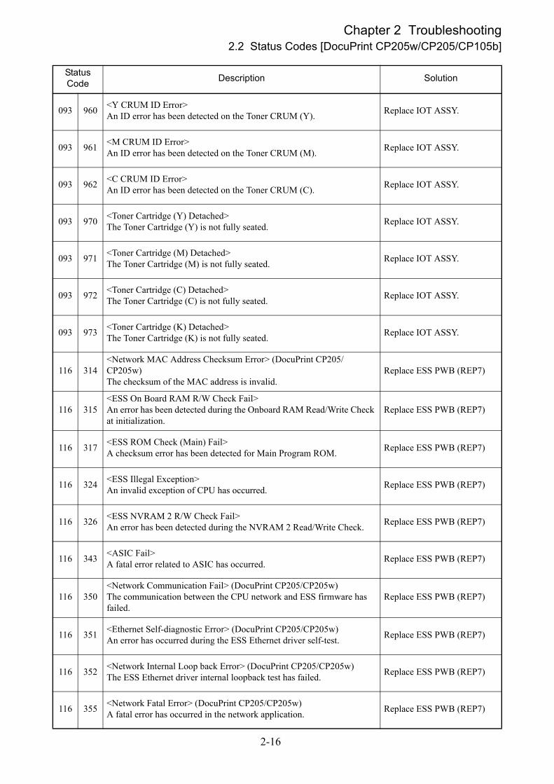
093 960<Y CRUM ID Error>An ID error has been detected on the Toner CRUM (Y).
Replace IOT ASSY.
093 961<M CRUM ID Error>An ID error has been detected on the Toner CRUM (M).
Replace IOT ASSY.
093 962<C CRUM ID Error>An ID error has been detected on the Toner CRUM (C).
Replace IOT ASSY.
093 970<Toner Cartridge (Y) Detached>The Toner Cartridge (Y) is not fully seated.
Replace IOT ASSY.
093 971<Toner Cartridge (M) Detached>The Toner Cartridge (M) is not fully seated.
Replace IOT ASSY.
093 972<Toner Cartridge (C) Detached>The Toner Cartridge (C) is not fully seated.
Replace IOT ASSY.
093 973<Toner Cartridge (K) Detached>The Toner Cartridge (K) is not fully seated.
Replace IOT ASSY.
116 314<Network MAC Address Checksum Error> (DocuPrint CP205/CP205w)The checksum of the MAC address is invalid.
Replace ESS PWB (REP7)
116 315<ESS On Board RAM R/W Check Fail>An error has been detected during the Onboard RAM Read/Write Check at initialization.
Replace ESS PWB (REP7)
116 317<ESS ROM Check (Main) Fail>A checksum error has been detected for Main Program ROM.
Replace ESS PWB (REP7)
116 324<ESS Illegal Exception>An invalid exception of CPU has occurred.
Replace ESS PWB (REP7)
116 326<ESS NVRAM 2 R/W Check Fail>An error has been detected during the NVRAM 2 Read/Write Check.
Replace ESS PWB (REP7)
116 343<ASIC Fail>A fatal error related to ASIC has occurred.
Replace ESS PWB (REP7)
116 350<Network Communication Fail> (DocuPrint CP205/CP205w)The communication between the CPU network and ESS firmware has failed.
Replace ESS PWB (REP7)
116 351<Ethernet Self-diagnostic Error> (DocuPrint CP205/CP205w)An error has occurred during the ESS Ethernet driver self-test.
Replace ESS PWB (REP7)
116 352<Network Internal Loop back Error> (DocuPrint CP205/CP205w)The ESS Ethernet driver internal loopback test has failed.
Replace ESS PWB (REP7)
116 355<Network Fatal Error> (DocuPrint CP205/CP205w)A fatal error has occurred in the network application.
Replace ESS PWB (REP7)
Status Code
Description Solution
2-16

Chapter 2 Troubleshooting2.2 Status Codes [DocuPrint CP205w/CP205/CP105b]
124 333<ASIC Failure>An ASIC failure has been detected.
Replace IOT ASSY.
191 310<XERO Life Over>The device (XERO DEVE LPH BELT ASSY) has reached its end of life.
Replace IOT ASSY.
193 700<Custom Toner Mode>The device is in the Custom Toner Mode.
Replace IOT ASSY.
Status Code
Description Solution
2-17

Chapter 4 Disassembly / Assembly


Contents
4.1 Preface .......................................................................................................................4-14.1.1 Before starting service work............................................................................................................ 4-1
4.2 Disassembly / Assembly.............................................................................................4-2PL1 DocuPrint CM205b ........................................................................................................................... 4-2
REP1 Kit Cover MSI ........................................................................................................................... 4-2
REP2 Kit Cover Front ......................................................................................................................... 4-3
REP3 Cover Side L............................................................................................................................. 4-5
REP4 IIT Assy..................................................................................................................................... 4-6
REP5 Cover Assy Top...................................................................................................................... 4-10
REP6 Kit Cover Assy Rear ............................................................................................................... 4-12
REP7 Kit Cover Rear Inner............................................................................................................... 4-13
REP8 ESS PWB ............................................................................................................................... 4-17
PL1 DocuPrint CP205w / CP205 / CP105b ........................................................................................... 4-19
REP1 Kit Cover MSI ......................................................................................................................... 4-19
REP2 Kit Cover Front ....................................................................................................................... 4-20
REP3 Cover Side L........................................................................................................................... 4-22
REP4 Cover Assy Top...................................................................................................................... 4-24
REP5 Kit Cover Rear Inner............................................................................................................... 4-26
REP6 Kit Cover Assy Rear ............................................................................................................... 4-29
REP7 ESS PWB ............................................................................................................................... 4-30
REP99.1 Safety Critical Components (SCC) .................................................................................... 4-32


Chapter 4 Disassembly / Assembly4.1 Preface
4.1 Preface
NOTE
When working on an item which is controlled as a spare part but the procedure therefore is not described,
observe carefully how the part is attached before removing the item.
NOTE
As a general rule, optional items are assumed to be removed from the equipment. However, you may work
with optional items attached if it does not disturb your work.
Safety Critical Component (SCC)
Control of the safety of components that are designated Safety Critical Components shall conform to Fuji Xerox Co. Ltd-
stipulated rules and regulations on Safety Critical Components.
As to replacement of any component designated SCC, the complete component unit must be replaced. It must never be
disassembled or no individual internal parts of it must be replaced.
Installation of any part other than the ones designated by Fuji Xerox Co. Ltd. shall be strictly prohibited because it can-
not be guaranteed in quality and safety.
Important Information Stored Component (ISC)
Important Information Stored Components store customers' important information they have entered after machine
installation. When replacing Important Information Stored Components, you must replace and discard them, following
the procedure described in Chapter 4 Adjustments.
Take care never to let customer information leak out.
4.1.1 Before starting service work
Start the procedure after turning off the power and removing the power cord from the outlet.
When performing the service operation around the FUSING UNIT, ensure that FUSING UNIT and its sur-
rounding area have cooled down sufficiently.
Pay sufficient attention to the parts during the procedure because they may be broken or may not perform their
functions properly if unreasonable force is applied.
Since various types of screws are used, ensure that the right screws are used in their right positions.
Use special caution not to confuse the screws for plastic and the ones for sheet metal, because using the wrong
type of screw may result in damage to the screw threads or other troubles.
Wear a wristband or the like as far as possible to remove static electricity of the human body.
4-1

Chapter 4 Disassembly / Assembly4.2 Disassembly / Assembly
4.2 Disassembly / Assembly
PL1 DocuPrint CM205b
REP1 Kit Cover MSI
[Removal]
1 Turn off the power switch, and then unplug the power cord from the power outlet.
2 Remove the Kit Cover MSI. (Fig.4-1)
①Release the tab from the hole by depressing the Kit Cover MSI toward the arrow direction,
and then remove the Kit Cover MSI.
Fig.4-1 Kit Cover MSI
[Replacement]
1 To install, carry out the removal steps in reverse order.
4-2

Chapter 4 Disassembly / Assembly4.2 Disassembly / Assembly
REP2 Kit Cover Front
[Removal]
1 Turn off the power switch, and then unplug the power cord from the power outlet.
2 Remove the Kit Cover MSI. (REP1)
3 Open the Kit Cover TNR.
4 Remove the Screw-Tapping(2) that fix the Kit Cover Front. (Fig.4-2)
①Remove the Screw-Tapping(2).
Fig.4-2 Kit Cover Front
4-3

Chapter 4 Disassembly / Assembly4.2 Disassembly / Assembly
5 Remove the Kit Cover Front. (Fig.4-3)
NOTE
Take care not to damage the Cover when releasing the Hook.
①Open the IIT Assy.
②Remove the Extension Tray.
③Release the right side of the Hook(3).
④Move the Kit Cover Front toward the arrow direction to remove it.
Fig.4-3 Kit Cover Front
[Replacement]
1 To install, carry out the removal steps in reverse order.
4-4
Chapter 4 Disassembly / Assembly4.2 Disassembly / Assembly
REP3 Cover Side L
[Removal]
1 Turn off the power switch, and then unplug the power cord from the power outlet.
2 Remove the Kit Cover MSI. (REP1)
3 Remove the Kit Cover Front. (REP2)
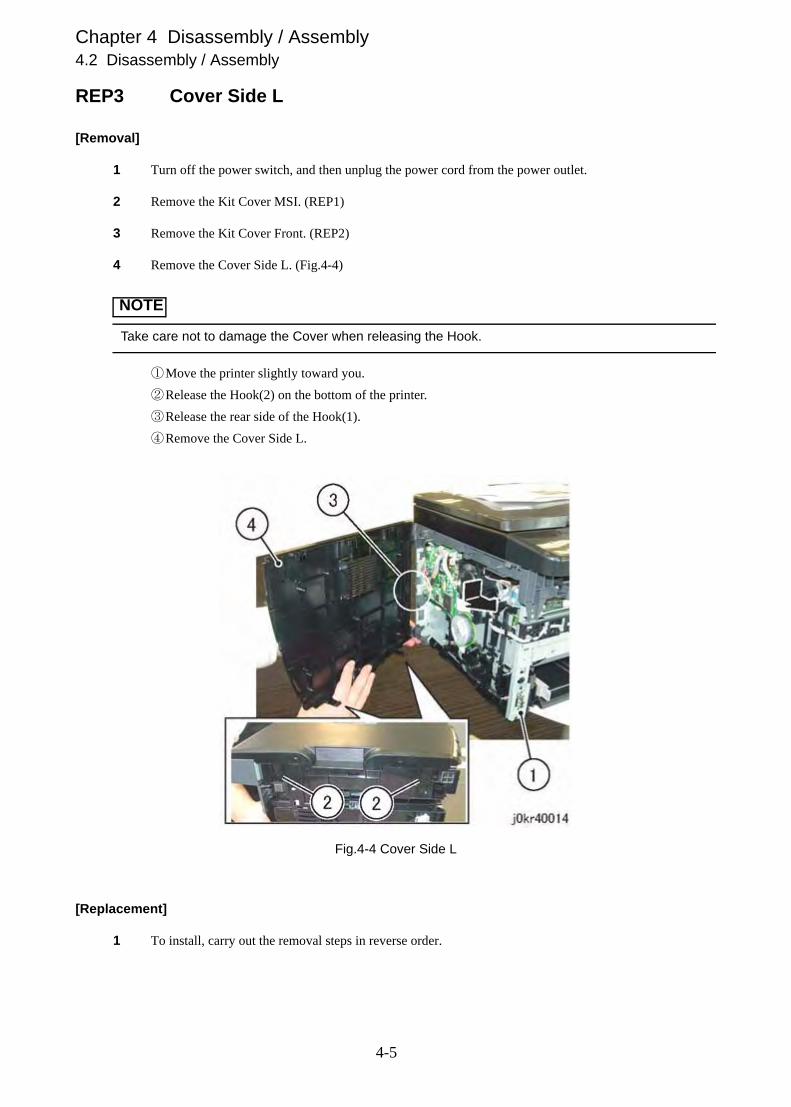
4 Remove the Cover Side L. (Fig.4-4)
NOTE
Take care not to damage the Cover when releasing the Hook.
①Move the printer slightly toward you.
②Release the Hook(2) on the bottom of the printer.
③Release the rear side of the Hook(1).
④Remove the Cover Side L.
Fig.4-4 Cover Side L
[Replacement]
1 To install, carry out the removal steps in reverse order.
4-5

Chapter 4 Disassembly / Assembly4.2 Disassembly / Assembly
REP4 IIT Assy
[Removal]
1 Turn off the power switch, and then unplug the power cord from the power outlet.
2 Remove the Kit Cover MSI. (REP1)
3 Remove the Kit Cover Front. (REP2)
4 Remove the Cover Side L. (REP3)
5 Disconnect the Connector(1) and Flat Cable(2). (Fig.4-5)
①Disconnect the Connector(1).
②Disconnect the Flat Cable(2).
Fig.4-5 IIT Assy
4-6

Chapter 4 Disassembly / Assembly4.2 Disassembly / Assembly
6 Remove the Screw(2) that fix the Holder Assy, ARM L and Holder Assy, ARM R of the IIT Assy.
(Fig.4-6)
①Open the IIT Assy.
②Remove the Screw(2).
③Pull the “Holder Assy, ARM L” and “Holder Assy, ARM R” toward you.
Fig.4-6 IIT Assy
4-7

Chapter 4 Disassembly / Assembly4.2 Disassembly / Assembly
7 Remove the Holder Assy, ARM L and Holder Assy, ARM R. (Fig.4-7)
①Raise the IIT Assy.
②Remove the Holder Assy, ARM L and Holder Assy, ARM R.
Fig.4-7 IIT Assy
4-8

Chapter 4 Disassembly / Assembly4.2 Disassembly / Assembly
8 Remove the IIT Assy. (Fig.4-8)
①Swing up the IIT Assy to the vertical position, and then pull it out upward in the arrow direction.
Fig.4-8 IIT Assy
[Replacement]
1 To install, carry out the removal steps in reverse order.
4-9

Chapter 4 Disassembly / Assembly4.2 Disassembly / Assembly
REP5 Cover Assy Top
[Removal]
1 Turn off the power switch, and then unplug the power cord from the power outlet.
2 Remove the Kit Cover MSI. (REP1)
3 Remove the Kit Cover Front. (REP2)
4 Remove the Cover Side L. (REP3)
5 Remove the IIT Assy. (REP4)
6 Remove the Screw(6) that fix the Cover Assy Top. (Fig.4-9)
①Remove the Screw(6).
Fig.4-9 Cover Assy Top
4-10

Chapter 4 Disassembly / Assembly4.2 Disassembly / Assembly
7 Remove the Cover Assy Top. (Fig.4-10)
NOTE
Take care not to damage the Cover when releasing the Hook.
①With the front end of the Cover Assy Top slightly lifted, unlock the Hook(3).
②Move the Cover Assy Top toward the arrow direction to remove it.
Fig.4-10 Cover Assy Top
[Replacement]
1 To install, carry out the removal steps in reverse order.
4-11

Chapter 4 Disassembly / Assembly4.2 Disassembly / Assembly
REP6 Kit Cover Assy Rear
[Removal]
1 Turn off the power switch, and then unplug the power cord from the power outlet.
2 Remove the Kit Cover Assy Rear. (Fig.4-11)
①Move the printer slightly toward you.
②Release the tab from the hole by depressing the Kit Cover Assy Rear toward the arrow direction,
and then remove the Kit Cover Assy Rear.
Fig.4-11 Kit Cover Assy Rear
[Replacement]
1 To install, carry out the removal steps in reverse order.
4-12

Chapter 4 Disassembly / Assembly4.2 Disassembly / Assembly
REP7 Kit Cover Rear Inner
[Removal]
1 Turn off the power switch, and then unplug the power cord from the power outlet.
2 Remove the Kit Cover MSI. (REP1)
3 Remove the Kit Cover Front. (REP2)
4 Remove the Cover Side L. (REP3)
5 Remove the IIT Assy. (REP4)
6 Remove the Cover Assy Top. (REP5)
7 Remove the Kit Cover Assy Rear. (REP6)
8 Open the Kit Cover TNR.
9 Remove the Screw-Tapping(4) that fix the Kit Cover Rear Inner. (Fig.4-12)
①Remove the Screw-Tapping(4).
Fig.4-12 Kit Cover Rear Inner
4-13
Chapter 4 Disassembly / Assembly4.2 Disassembly / Assembly
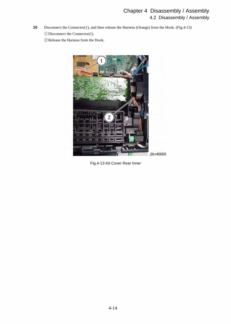
10 Disconnect the Connector(1), and then release the Harness (Orange) from the Hook. (Fig.4-13)
①Disconnect the Connector(1).
②Release the Harness from the Hook.
Fig.4-13 Kit Cover Rear Inner
4-14

Chapter 4 Disassembly / Assembly4.2 Disassembly / Assembly
11 Remove the Kit Cover Rear Inner. (Fig.4-14)
NOTE
Take care not to damage the Cover when releasing the Hook.
①Pull up the Lever(2).
②Release the left side Hook(2).
③Remove the Kit Cover Rear Inner.
Fig.4-14 Kit Cover Rear Inner
4-15

Chapter 4 Disassembly / Assembly4.2 Disassembly / Assembly
[Replacement]
1 To install, carry out the removal steps in reverse order.
NOTE
Make sure that the tab on the Kit Cover Rear Inner fits the hole on the Kit Cover TNR. (Fig.4-15)
Fig.4-15 Kit Cover Rear Inner
4-16

Chapter 4 Disassembly / Assembly4.2 Disassembly / Assembly
REP8 ESS PWB
[Removal]
Static electricity may damage electrical parts. Always wear a wrist band during servicing. If a wrist band is
not available, touch some metallic parts before servicing to discharge the static electricity.
1 Turn off the power switch, and then unplug the power cord from the power outlet.
2 Remove the Kit Cover MSI. (REP1)
3 Remove the Kit Cover Front. (REP2)
4 Remove the Cover Side L. (REP3)
5 Remove the IIT Assy. (REP4)
6 Remove the Cover Assy Top. (REP5)
7 Remove the Kit Cover Assy Rear. (REP6)
8 Remove the Kit Cover Rear Inner. (REP7)
4-17

Chapter 4 Disassembly / Assembly4.2 Disassembly / Assembly
9 Remove the ESS PWB. (Fig.4-16)
①Disconnect the Connector(2).
②Disconnect the Flat Cable(2).
③Remove the Screw(4).
④Remove the ESS PWB.
Fig.4-16 ESS PWB
[Replacement]
1 To install, carry out the removal steps in reverse order.
4-18

Chapter 4 Disassembly / Assembly4.2 Disassembly / Assembly
PL1 DocuPrint CP205w / CP205 / CP105b
REP1 Kit Cover MSI
[Removal]
1 Turn off the power switch, and then unplug the power cord from the power outlet.
2 Remove the Kit Cover MSI. (Fig.4-17)
①Release the tab from the hole by depressing the Kit Cover MSI toward the arrow direction,
and then remove the Kit Cover MSI.
Fig.4-17 Kit Cover MSI
[Replacement]
1 To install, carry out the removal steps in reverse order.
4-19
Chapter 4 Disassembly / Assembly4.2 Disassembly / Assembly
REP2 Kit Cover Front
[Removal]
1 Turn off the power switch, and then unplug the power cord from the power outlet.
2 Remove the Kit Cover MSI. (REP1)
3 Open the Kit Cover TNR.
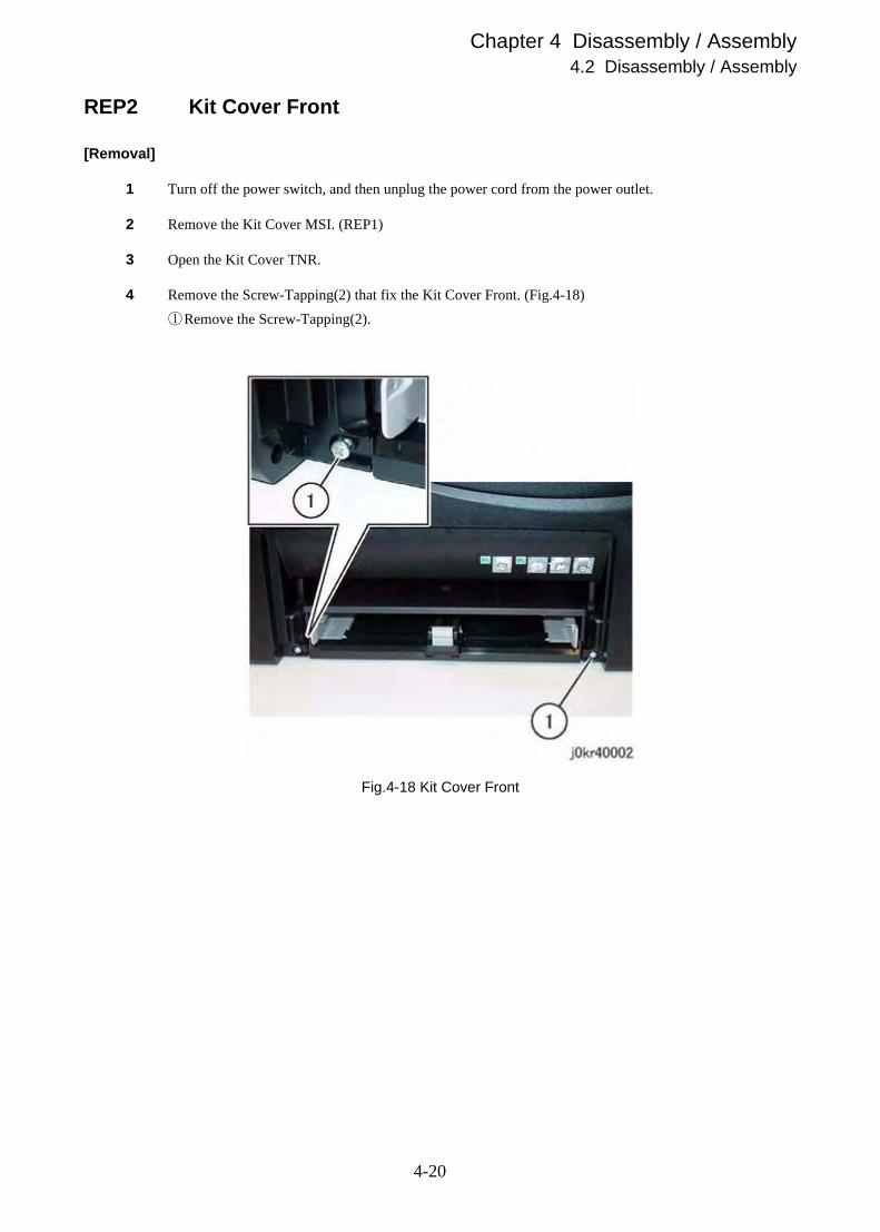
4 Remove the Screw-Tapping(2) that fix the Kit Cover Front. (Fig.4-18)
①Remove the Screw-Tapping(2).
Fig.4-18 Kit Cover Front
4-20
Chapter 4 Disassembly / Assembly4.2 Disassembly / Assembly
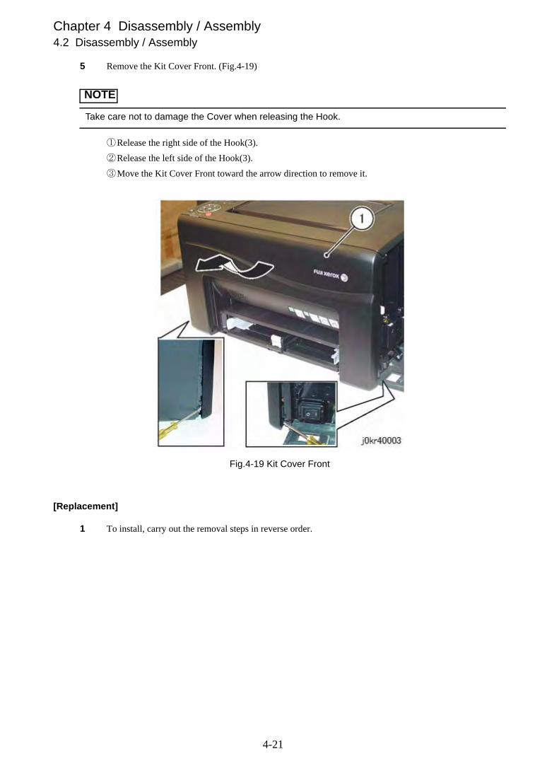
5 Remove the Kit Cover Front. (Fig.4-19)
NOTE
Take care not to damage the Cover when releasing the Hook.
①Release the right side of the Hook(3).
②Release the left side of the Hook(3).
③Move the Kit Cover Front toward the arrow direction to remove it.
Fig.4-19 Kit Cover Front
[Replacement]
1 To install, carry out the removal steps in reverse order.
4-21

Chapter 4 Disassembly / Assembly4.2 Disassembly / Assembly
REP3 Cover Side L
[Removal]
1 Turn off the power switch, and then unplug the power cord from the power outlet.
2 Remove the Kit Cover MSI. (REP1)
3 Remove the Kit Cover Front. (REP2)
4 Remove the Cover Side L. (Fig.4-20)
NOTE
Take care not to damage the Cover when releasing the Hook.
①Move the printer slightly toward you.
②Release the Hook(2) on the bottom of the printer.
③Release the rear side of the Hook(1).
④Move the Cover Side L toward arrow direction to remove it.
Fig.4-20 Cover Side L
4-22

Chapter 4 Disassembly / Assembly4.2 Disassembly / Assembly
[Replacement]
1 To install, carry out the removal steps in reverse order.
NOTE
When attaching the Cover Side L, make sure that the rear side of the Tab(2) were attached to the
inside of the Cover Assy Rear. (Fig.4-21)
Fig.4-21 Cover Side L
4-23

Chapter 4 Disassembly / Assembly4.2 Disassembly / Assembly
REP4 Cover Assy Top
[Removal]
1 Turn off the power switch, and then unplug the power cord from the power outlet.
2 Remove the Kit Cover MSI. (REP1)
3 Remove the Kit Cover Front. (REP2)
4 Remove the Cover Side L. (REP3)
5 Remove the Screw(2) and disconnect the Connector(1) that fix the Cover Assy Top. (Fig.4-22)
①Disconnect the Connector(1).
②Remove the Screw(2).
Fig.4-22 Cover Assy Top
4-24

Chapter 4 Disassembly / Assembly4.2 Disassembly / Assembly
6 Remove the Cover Assy Top. (Fig.4-23)
NOTE
Take care not to damage the Cover when releasing the Hook.
①Release the right side of the Hook(2).
②Move the Cover Assy Top toward the arrow direction to remove it.
Fig.4-23 Cover Assy Top
[Replacement]
1 To install, carry out the removal steps in reverse order.
4-25

Chapter 4 Disassembly / Assembly4.2 Disassembly / Assembly
REP5 Kit Cover Rear Inner
[Removal]
1 Turn off the power switch, and then unplug the power cord from the power outlet.
2 Remove the Kit Cover MSI. (REP1)
3 Remove the Kit Cover Front. (REP2)
4 Remove the Cover Side L. (REP3)
5 Remove the Cover Assy Top. (REP4)
6 Open the Kit Cover Assy Rear.
7 Open the Kit Cover TNR.
8 Remove the Screw-Tapping(4) that fix the Kit Cover Rear Inner. (Fig.4-24)
①Remove the Screw-Tapping(4).
Fig.4-24 Kit Cover Rear Inner
4-26

Chapter 4 Disassembly / Assembly4.2 Disassembly / Assembly
9 Disconnect the Connector(1), and then release the Harness (Orange) from the Hook. (Fig.4-25)
①Disconnect the Connector(1).
②Release the Harness from the Hook.
Fig.4-25 Kit Cover Rear Inner
4-27

Chapter 4 Disassembly / Assembly4.2 Disassembly / Assembly
10 Remove the Kit Cover Rear Inner. (Fig.4-26)
NOTE
Take care not to damage the Cover when releasing the Hook.
①Pull up the Lever(2).
②Release the left side Hook(2).
③Remove the Kit Cover Rear Inner.
Fig.4-26 Kit Cover Rear Inner
[Replacement]
1 To install, carry out the removal steps in reverse order.
4-28

Chapter 4 Disassembly / Assembly4.2 Disassembly / Assembly
REP6 Kit Cover Assy Rear
[Removal]
1 Turn off the power switch, and then unplug the power cord from the power outlet.
2 Remove the Kit Cover Assy Rear. (Fig.4-27)
①Move the printer slightly toward you.
②Release the tab from the hole by depressing the Kit Cover Assy Rear toward the arrow direction,
and then remove the Kit Cover Assy Rear.
Fig.4-27 Kit Cover Assy Rear
[Replacement]
1 To install, carry out the removal steps in reverse order.
4-29

Chapter 4 Disassembly / Assembly4.2 Disassembly / Assembly
REP7 ESS PWB
[Removal]
Static electricity may damage electrical parts. Always wear a wrist band during servicing. If a wrist band is
not available, touch some metallic parts before servicing to discharge the static electricity.
1 Turn off the power switch, and then unplug the power cord from the power outlet.
2 Remove the Kit Cover MSI. (REP1)
3 Remove the Kit Cover Front. (REP2)
4 Remove the Cover Side L. (REP3)
5 Remove the ESS PWB. (Fig.4-28)
①Disconnect the Connector(2).
②Disconnect the Flat Cable(2).
③Loosen the Screw(1).
④Remove the Screw(4).
⑤Remove the ESS PWB.
Fig.4-28 ESS PWB
4-30

Chapter 4 Disassembly / Assembly4.2 Disassembly / Assembly
[Replacement]
1 To install, carry out the removal steps in reverse order.
4-31

Chapter 4 Disassembly / Assembly4.2 Disassembly / Assembly
REP99.1 Safety Critical Components (SCC)
Any part marked with SCC is a Safety Critical Component. As to replacement of any SCC, the complete
component unit must be replaced. It must never be disassembled or no individual internal parts of it must
be replaced. Further, when a spare part is provided with the instructions, the CEs are required to follow
them.
Installation of any part other than the ones designated by Fuji Xerox Co., Ltd. shall be strictly prohibited
because it cannot be guaranteed in quality and safety.
4-32

Chapter 10 Machine Overview


Contents
10.1 Printing Process .....................................................................................................10-110.1.1 Summary of Printing Process ..................................................................................................... 10-1
10.1.2 Schematic Diagram of Printing Process ..................................................................................... 10-2
10.2 Paper Path..............................................................................................................10-310.2.1 Paper Path .................................................................................................................................. 10-3
10.2.2 Layout of Paper Path .................................................................................................................. 10-4
10.2.3 Feeding from Multipurpose feeder (MPF) ................................................................................... 10-5
10.2.3.1 Multiple Sheet Feed Prevention.......................................................................................... 10-6
10.2.4 Feeding from Priority Sheet Inserter (PSI).................................................................................. 10-7
10.2.5 Feeding in Registration Section .................................................................................................. 10-8
10.2.5.1 Lead-edge Registration....................................................................................................... 10-9
10.2.6 Transfer/Fusing/Exit.................................................................................................................. 10-10
10.3 Data Flow .............................................................................................................10-11
10.4 Operation Modes..................................................................................................10-1210.4.1 Operation Modes ...................................................................................................................... 10-12
10.5 Control ..................................................................................................................10-1310.5.1 Process Control ........................................................................................................................ 10-13
10.5.1.1 Potential Control ............................................................................................................... 10-13
10.5.1.2 Toner Density Control ....................................................................................................... 10-14
10.5.1.3 High Area Coverage Mode ............................................................................................... 10-14
10.5.1.4 Admix Mode...................................................................................................................... 10-14
10.5.1.5 ADC Sensor Adjustment ................................................................................................... 10-14
10.5.2 Color Registration Control......................................................................................................... 10-15
10.5.3 Fusing Unit Control ................................................................................................................... 10-16
10.5.3.1 Fusing Unit temperature control........................................................................................ 10-16
10.5.3.2 Cooling down .................................................................................................................... 10-16
10.6 Drive Transmission Route ....................................................................................10-1710.6.1 DRIVE ASSY MOT ................................................................................................................... 10-17
10.7 Functions of SCANNER ASSY [DocuPrint CM205b] ...........................................10-1910.7.1 Document Scanning.................................................................................................................. 10-19
10.7.2 Document Scanning at Platen (IIT)........................................................................................... 10-20
10.7.3 Document Scanning at Auto Document Feeder (ADF)............................................................. 10-21
10.7.4 Paper Path of ADF.................................................................................................................... 10-22


Chapter 10 Machine Overview10.1 Printing Process
10.1 Printing Process
10.1.1 Summary of Printing Process
This device is an LED-based full-color xerographic printer operating on a tandem printing system that has four color-
specific drum/developer sets for yellow, magenta, cyan, and black (YMCK).
The four color-separated images of the original document are created with toner on the drums and then transferred in reg-
istration onto the IBT Belt (IBT = Intermediate Belt Transfer) to reproduce a full color image. The completed toner
image is transferred and fixed on the print medium, and then output as a print.
The printing process of this printer is composed of the following basic steps:
(1) Charging:.......................The drum surface is electrically charged.
(2) Exposure:.......................The image is formed on the drum surface by the light from the LEDs
(Light Emitting Diodes).
(3) Development: ................The image is developed with toner.
(4) Primary Transfer: ..........The four color separation images on the drums are transferred onto the IBT Belt.
(5) Cleaning: .......................The drums are electrically neutralized and the toner remaining on the drums and
BCRs is removed.
(6) Secondary Transfer: ......The toner image on the IBT Belt is transferred onto the medium.
(7) Neutralization:...............Electric charge of the paper is eliminated.
(8) Cleaning: .......................The toner remaining on the IBT Belt and 2nd BTR is removed.
(9) Fusing:...........................The toner is fixed to the print medium by heat and pressure.
�������� ��� ��
���� ���� ���� � �
����������������� ��!��
"�!�#�
� ��!��"�!�#�
� ��!��"�!�#�
� ��!��"�!�#�
��"���$ ����%&�����'� ������(��)� �*��%'��
�+� �����"�!
�,� -'%"�!
�.� /�'����"0����"��
����������������
��"���$ ����%&�����'� ������(��)� �*��%'��
�+� �����"�!
����������������
��"���$ ����%&�����'� ������(��)� �*��%'��
�+� �����"�!
����������������
��"���$ ����%&�����'� ������(��)� �*��%'��
�+� �����"�!
��1��2��$ ����%&������� ������
�3�
�4� �����"�!
5��6366#5�
���� ���� ���� �7�
���� ���� ���� ���
���� ���� ���� �5�
10-1

Chapter 10 Machine Overview10.1 Printing Process
10.1.2 Schematic Diagram of Printing Process
The outline of the printing process is shown in the figure below.
Y M C K
: 用紙搬送
Eliminator[(7) 除電]
Cleaning Blade[(8) 清掃]
FUSING ASSY[(9) 定着]
2nd BTR[(6) 二次転写]
: LED点灯
LPH[(2) 露光]
Magnet Roll[(3) 現像]
1st BTR[(4) 一次転写]
Cleaning Blade[(5) 清掃]
Cleaning Roll[(5) 清掃]
ドラム
ベルト
BCR[(1) 帯電]
Transfer Belt
KaS10002AA
LED Lights
Paper transfer
[(9) Fusing]
[(8) Cleaning]
[(7) Neutralization]
[(6) Secondary transfer]
[(4) Primary transfer]
Belt
[(5) Cleaning]
[(1) Charging]
[(3) Development]
[(2) Exposure] [(5) Cleaning]
Drum
10-2

Chapter 10 Machine Overview10.2 Paper Path
10.2 Paper Path
10.2.1 Paper Path
重送防止重送防止
Registration
Transfer Belt
Fusing
Exit Roll in the Fusing Assy
Top Cover
PSI
Motor drive / Solenoid /Feed Roll
MPF
Motor drive / Solenoid /Feed Roll
Motor drive / Clutch /Regi Roll
Motor drive / Belt /2nd BTR
Motor drive / Heat Roll /Pressure Belt
KaS10016AA
リードエッジレジストレーション
Multiple Sheet feed
Prevention
.Lead edge
registration
Multiple Sheet feed
Prevention
10-3

Chapter 10 Machine Overview10.2 Paper Path
10.2.2 Layout of Paper Path
Y M C K
: 用紙搬送
: 用紙に関するセンサー
Exit Roll [Fusing]
Heat Roll [Fusing]
Pressure Belt[Fusing]
Exit Sensor [Fusing]
2nd BTR
Regi Roll (rubber)[Registration]
Regi Roll (pinch)[Registration]
Regi Sensor[Registration]
Transfer Belt
Separator Roll [PSI & MPF]
No Paper Sensor [PSI & MPF]
Feed Roll [PSI & MPF]KaS10017AA
Paper transfer
Paper sensors
10-4

Chapter 10 Machine Overview10.2 Paper Path
10.2.3 Feeding from Multipurpose feeder (MPF)
When sheet feeding from the Multipurpose feeder (MPF) starts, the Feed Roll rotates, driven by the DRIVE ASSY MOT
and controlled by the SOLENOID FEED MSI, to feed the sheet to the position where it is nipped between the Feed Roll
and the Retard Roll.
As the Feed Roll rotates, the CAM MSI L and CAM MSI R also rotate to lift the PLATE ASSY BOTTOM via the ARM
MSI L and ARM MSI R to the position for sheet feeding.
KaS10018AA
Feed Roll
Retard Roll
PLATE ASSY BOTTOM
ARM MSI L
ARM MSI RCAM MSI L
CAM MSI R
SOLENOID FEED MSIPLATE ASSY BOTTOM Multipurpose feeder
10-5

Chapter 10 Machine Overview10.2 Paper Path
10.2.3.1 Multiple Sheet Feed Prevention
The sheets set in a tray or cassette is occasionally stuck together along the edges. The stuck sheets cause a multiple sheet
feed or a jam. The sheets are fed by the Feed Roll to a position between the Feed Roll and the Retard Roll. Normally,
when only one sheet passes through this position, both the Feed Roll and Retard Roll rotate to allow the sheet to pass.
However, when two sheets, stuck together, attempt to pass through this position, only the Feed Roll rotates and the
Retard Roll is locked, allowing only the upper sheet to pass by separating itself from the lower sheet that is stopped by
the friction with the Retard Roll at rest.
The Retard Roll is being pushed toward the Feed Roll by spring pressure, and controlled by the torque limiter (Clutch
Assy Friction) with which it is coupled.
KaS06019AA
Feed Roll
Retard Roll
Retard Roll
PLATE ASSY BOTTOM
CLUTCH ASSY FRICTION
10-6

Chapter 10 Machine Overview10.2 Paper Path
10.2.4 Feeding from Priority Sheet Inserter (PSI)
When feeding from the Priority Sheet Inserter (PSI) starts, the Feed Roll rotates, driven by the DRIVE ASSY MOT and
controlled by the SOLENOID FEED MSI, to feed the sheet to the position where it is nipped between the Feed Roll and
the Retard Roll.
Since the paper path from the MPF and the paper path from the PSI are the same, the sheets loaded in the PSI positioned
nearer to the Feed Roll are given the higher priority in feeding, if both the MPF and the PSI are loaded.
SOLENOID FEED MSI
Priority Sheet Inserter KaS10020AA
Feed Roll
Paper (PSI)
PLATE ASSY BOTTOMRetard Roll
Paper (MPF)
10-7

Chapter 10 Machine Overview10.2 Paper Path
10.2.5 Feeding in Registration Section
The sheet fed out of the MPF or PSI is forwarded to the registration section, driven by the DRIVE ASSY MOT and con-
trolled by the CLUTCH REGI.
When the sheet reaches the registration section, its lead-edge position is adjusted (Refer to "10.2.5.1 Lead-edge Registra-
tion"), and then the sheet is forwarded to the toner transfer section (2nd BTR).
Regi Roll
CLUTCH REGI
Paper
Regi Roll
KaS10021AA
10-8
Chapter 10 Machine Overview10.2 Paper Path
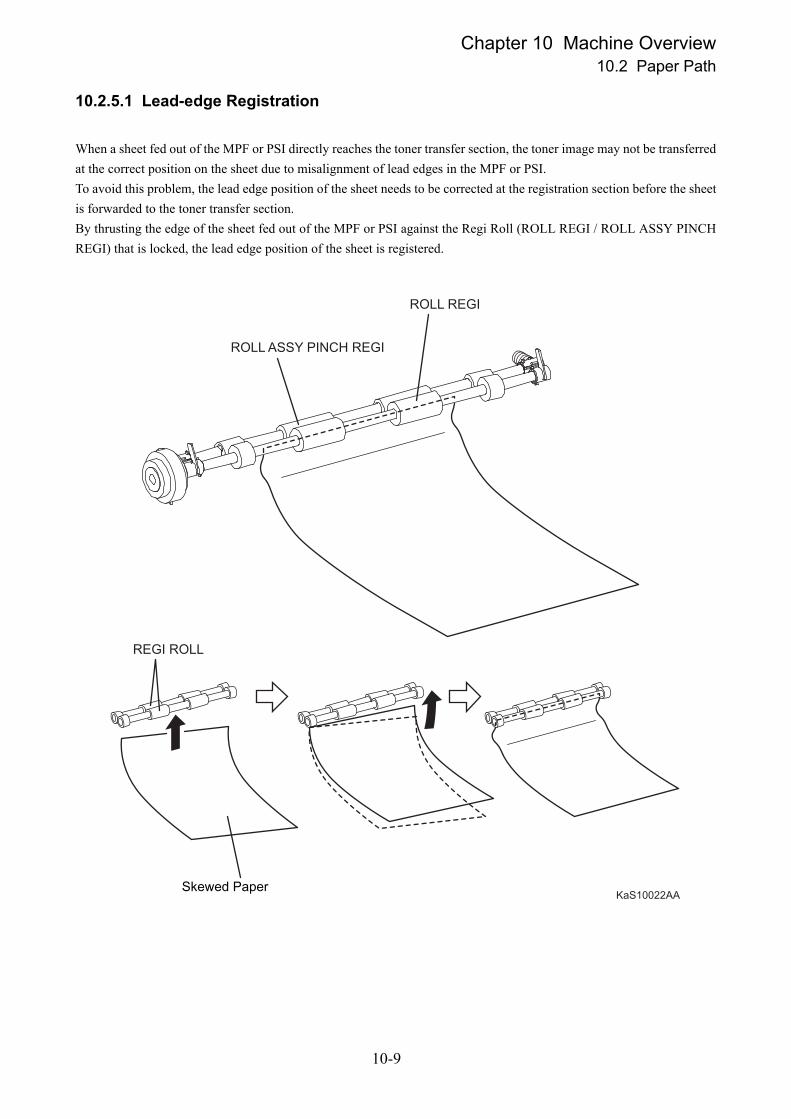
10.2.5.1 Lead-edge Registration
When a sheet fed out of the MPF or PSI directly reaches the toner transfer section, the toner image may not be transferred
at the correct position on the sheet due to misalignment of lead edges in the MPF or PSI.
To avoid this problem, the lead edge position of the sheet needs to be corrected at the registration section before the sheet
is forwarded to the toner transfer section.
By thrusting the edge of the sheet fed out of the MPF or PSI against the Regi Roll (ROLL REGI / ROLL ASSY PINCH
REGI) that is locked, the lead edge position of the sheet is registered.
KaS10022AA
ROLL REGI
ROLL ASSY PINCH REGI
REGI ROLL
斜めに搬送された用紙Skewed Paper
10-9

Chapter 10 Machine Overview10.2 Paper Path
10.2.6 Transfer/Fusing/Exit
While the sheet that passed the registration section passes through the toner transfer position where it is nipped between
the IBT Belt and the 2nd BTR that rotate driven by the DRIVE ASSY MOT, the toner image on the IBT Belt is trans-
ferred onto the sheet. As the sheet is forwarded to the exit section, the toner image is fused onto the sheet surface by the
Heat Roll that rotates driven by the DRIVE ASSY MOT.
At the exit section, the sheet is ejected by the Exit Roll that rotates in the exit direction driven by the DRIVE ASSY
MOT.
Belt KaS10023AA
2nd BTR
Heat Roll
Exit Roll
Pressure Belt
10-10

Chapter 10 Machine Overview10.3 Data Flow
10.3 Data Flow
The print data (electric signal) from the printer controller flows as shown below before it is turned into a print.
����������
10-11
Chapter 10 Machine Overview10.4 Operation Modes
10.4 Operation Modes
10.4.1 Operation Modes
The printer can be operated in the following four modes:
Printing Mode
The printer is under printing.
Ready Mode
The printer is ready for printing.
Low Power Mode
The printer is under power saving.
When the predetermined time elapses in the Ready Mode, the device goes into the Low Power Mode to reduce
standby power consumption.
Sleep Mode
The printer is under power saving.
When the predetermined time elapses in the Low Power Mode, the device goes into the Sleep Mode to reduce
standby power consumption.
10-12

Chapter 10 Machine Overview10.5 Control
10.5 Control
10.5.1 Process Control
The parameters related to image formation must be corrected to stabilize printing. The control of the entire printing pro-
cess including the parameter correction control is called "process control".
The process control is performed by the following two methods after every 30 cumulative prints upon termination of a
print run or during a continuous run:
Potential Control
Toner Density Control
To supplement these two controls, the following controls are provided:
High Area Coverage Mode
Admix Mode
10.5.1.1 Potential Control
To stabilize the print image density, the drum charging voltage, the developing DC voltage, and the LED light amount of
the LPH are adjusted according to the ever-changing developing capability of each color developer. The adjusted drum
charging voltage, the developing DC voltage, and the LED light amount of the LPH are fed back to keep the print image
density constant.
The outline of control is as follows:
1) The HUMIDITY SENSOR (temperature and humidity sensor) detects the temperature and humidity.
2) The patches of respective colors (yellow, magenta, cyan, and black) for the potential control are generated
and transferred onto the Belt.
3) The ADC Sensor (density sensor) detects the density of the patches on the Belt.
4) The drum charging voltage, the developing DC voltage, and the LED light amount of the LPH are adjusted
for each color according to the detected patch density.
10-13

Chapter 10 Machine Overview10.5 Control
10.5.1.2 Toner Density Control
The toner density must be kept constant to stabilize the print image quality. The control system for this purpose is called
toner density control.
1) ICDC (Image Count Dispense Control)
The quantity of the toner to be consumed in the developing process is calculated in terms of toner dispensing
time based on the quantity of the video signals that have been input to the LPH. The amount of the toner to
be fed to the developer section is controlled by turning on the Toner Motor for the toner-dispensing time thus
calculated.
2) ADC (Auto Density Control)
The patches of respective colors (yellow, magenta, cyan, and black) for the toner density control are gener-
ated under the specified potential condition, and then transferred onto the Belt. The ADC Sensor measures
the densities of these patches and compares them with the reference value. If the toner density is lower than
the reference value, the toner dispense quantity is increased at the next printing. If the toner density is higher
than the reference value, the toner dispense quantity is reduced at the next printing. The toner dispense quan-
tity is calculated in terms of the toner dispensing time on a color-by-color basis.
10.5.1.3 High Area Coverage Mode
A continuous printing of a high area coverage data that exceeds the extra toner dispense capability causes the toner den-
sity in the developer to be lowered.
The High Area Coverage Mode postpones the next page feed and dispenses the toner during this time if the toner dis-
pense time has reached the specified value during a continuous printing.
10.5.1.4 Admix Mode
This mode executes extra toner dispensation to prevent the toner density from being lowered whenever the value of the
toner density control patch measured by the ADC Sensor falls far below the reference value. If the toner density level
cannot be recovered even after this operation, it is determined that the toner has run out.
10.5.1.5 ADC Sensor Adjustment
The ADC Sensor is a reflection type sensor that irradiates the light from its LED onto the target and detects the reflected
light at its photoreceptor and outputs electric signals responsive to the amount of the detected light. To ensure an accurate
patch density measurement, the surfaces of the ADC Sensor is cleaned to remove soil due to toner, etc., and the light
quantity adjustment is made so that the reflected light quantity satisfies the predetermined value when the patch for
potential control and toner density control are created.
10-14

Chapter 10 Machine Overview10.5 Control
10.5.2 Color Registration Control
The printer uses a tandem system where the drums and developers are arranged respectively for each of yellow, magenta,
cyan, and black colors. Since the four color-separated images are overlaid one another onto the print medium, a color
shift may occur. The color registration control calculates how much the registration is shifted, and adjusts the LPH write
timing.
Color registration control is performed based on the change in the internal temperature of the device.
The control is outlined below:
1) With no toner on the Belt, the output value of the Sensor is measured to determine the threshold value.
2) The patch for color registration control is generated on the Belt.
For Type A, one patch is created on the AntiDrive (AD) side. For Type B, two patches are created, one for
each on the AD side and on the Drive side.
3) The density of the patch is measured by the Sensor.
4) The shift correction amount is calculated from the threshold value determined in 1) and the patch density
measured in 3).
5) The LPH write timing is changed according to the shift correction amount.
10-15

Chapter 10 Machine Overview10.5 Control
10.5.3 Fusing Unit Control
10.5.3.1 Fusing Unit temperature control
To control the Fusing Unit temperature, the target temperature is set, and then the Heater Lamp is turned on/off so that
the surface temperature of the Heat Roll satisfies the target value.
The surface temperature of the Heat Roll is detected by the Temp. Sensor (STS: Soft Touch Sensor) in the middle of the
Heat Roll and the Temp. Sensors at the end sections. When the temperature detected is higher than the target value, the
Heater Lamp will be turned OFF. When the temperature detected is below the target value, the Heater Lamp will be
turned ON.
However, the STS may detect a temperature lower than the actual value when an error occurs during the temperature
detection. To prevent, in such a case, the Heater Lamp from activating for too long a duration until it melts or burns the
Fusing Unit Assy, the Heater Lamp is turned off unless Warm-up is completed within the specified time.
The target temperature varies depending on the printer status such as Standby, Printing, or Process Control, and is
calibrated according to the temperature difference between the middle section and the end section of the Heat Roll, the
printing mode, and the input power supply voltage.
10.5.3.2 Cooling down
As the printing continues, the temperature of the Heat Roll becomes nonuniform between the area that contacts the sheet
and the area that does not. In such a case, the paper feeding is suspended for a certain duration to compensate for the tem-
perature nonuniformity of the Heat Roll. This is called "Cooling Down".
When the temperature of the Heat Roll end is high, cooling down is performed to lower the temperature to the target
value.
10-16

Chapter 10 Machine Overview10.6 Drive Transmission Route
10.6 Drive Transmission Route
10.6.1 DRIVE ASSY MOT
The torque of the DRIVE ASSY MOT is transmitted through the route shown below.
DRIVE ASSY MOT
MOTOR ASSY MAIN
GEAR PF1
GEAR PF2
[ 駆動部品 ][ PAPER FEED DRIVE ]
GEAR HR
GEAR IDLER HR
[ HEAT ROLL ]
CLUTCH REGI
GEAR PH6 GEAR PH4
SOLENOID FEED MSI
GEAR PH5
[ EXIT ROLL ]FUSING ASSY
GEAR IDLER EXIT
GEAR EXIT
[ FEED ROLL ] [ REGI ROLL ]REGI ASSYMPF & PSI
GEAR FEED
GEAR PH3 GEAR F3
GEAR F4
DRIVE ASSY PH
KaS10042AA
[Name of moving parts]
10-17

Chapter 10 Machine Overview10.6 Drive Transmission Route
KaS10043AA
FRONT
: 駆動伝達経路
[ 駆動部品 ][ PAPER FEED DRIVE ]
DRIVE ASSY MOT
MOTOR ASSYMAIN
GEAR PF1
GEAR PF2
GEAR HR
GEAR IDLER HR
[ HEAT ROLL ]
CLUTCH REGIGEAR PH6
SOLENOID FEED MSI
GEAR PH5
[ EXIT ROLL ]
GEAR IDLER EXITGEAR EXIT
[ FEED ROLL ]
[ REGI ROLL ]
GEAR FEED
GEAR PH3
GEAR F4
DRIVE ASSY PHGEAR PH4
GEAR F3
FUSING ASSY
[Name of moving parts]
Indicates
the engagement
gears.
10-18

Chapter 10 Machine Overview10.7 Functions of SCANNER ASSY [DocuPrint CM205b]
10.7 Functions of SCANNER ASSY [DocuPrint CM205b]
10.7.1 Document Scanning
The SCANNER ASSY consists of the Image Input Terminal (IIT) and the Auto Document Feeder (ADF).
Document scanning is performed by the Carriage Assy in the Image Input Terminal.
The Carriage Assy consists of components such as the CMOS Image Sensor for converting image to data, the LED Array
for illuminating the original, and the Rod Scope for converting the original image to a full-size erect image.
KaA10009AA
ADF
IIT
Carriage Assy
原稿
LEDアレイロッドレンズアレイ
CMOSイメージセンサー
Document
Rod Scope
CMOS Image Sensor
LED Array
10-19

Chapter 10 Machine Overview10.7 Functions of SCANNER ASSY [DocuPrint CM205b]
10.7.2 Document Scanning at Platen (IIT)
While the Carriage Assy in the IIT moves at the speed corresponding to the set magnification, the LED Array illuminates
the document, allowing the reflected image to be read by the CMOS Image Sensor through the Rod Scope.
KaA10010AA
ADF
IIT
原稿
Carriage AssyCarriage Assy
原稿
LED アレイロッドレンズアレイ
CMOSイメージセンサー
Document
Rod Scope
CMOS Image Sensor
LED Array
Document
10-20

Chapter 10 Machine Overview10.7 Functions of SCANNER ASSY [DocuPrint CM205b]
10.7.3 Document Scanning at Auto Document Feeder (ADF)
When the document being fed by the torque from the ADF Motor at the speed corresponding to the set magnification
passes the Scanner Home Position (CVT: Constant Velocity Transport) of the Carriage Assy in the IIT, the LED Array
illuminates the document, allowing the reflected image to be read by the CMOS Image Sensor through the Rod Scope.
KaA10011AA
CVT Position
ADF
IIT
原稿
Carriage Assy
原稿
LEDアレイロッドレンズアレイ
CMOSイメージセンサー
Document
Rod Scope
CMOS Image Sensor
LED Array
Document
10-21

Chapter 10 Machine Overview10.7 Functions of SCANNER ASSY [DocuPrint CM205b]
10.7.4 Paper Path of ADF
When the sheet feeding from the Document Feeder Tray of the ADF starts, the Nudger Roll and the Feed Roll that rotate
driven by the torque from the ADF Motor. The sheet is nipped between the Feed Roll and the ADF Separator Pad while
being fed into the ADF.
Inside the ADF, the sheet is fed by the Takeaway Roll that rotates by the torque from the ADF Motor to the Scanner
Home (CVT: Constant Velocity Transport) Position in the Carriage Assy, and is scanned.
After being scanned, the sheet is ejected to the Document Output Tray of the ADF by the Exit Roll that rotates by the
torque from the ADF Motor.
Exit Roll
Home Position (CVT Position)
Takeaway Roll
Nudger RollFeed Roll
Feed Sensor Document Sensor
RETARD PAD ADF
: 用紙搬送
: 用紙に関するセンサー
KaA10012AA
Paper transfer
Paper sensors
10-22
FX CS / TS
Name : Date : Publication No. :
Job Title : Employee No. : Title of Publication :
Date and Revision of Publication :
OpCo (Country) :
Mailing Address :
Page No. - Figure No. Description of Error or Deficiency (please be specific).
Please check if answer is requested. No→□ Yes→□
If yes, be sure to fill in Name, Job Title, Employee No., OpCo name and Mailing Address
Type or print using black pencil or ink:
Mail to your Technical Support Department and they will pass to us. (Customer Engineer / Dealer Engineer→OpCo Technical Support Department→FX CS / TS
PUBLICATION COMMENT SHEET
Use this feedback sheet to make us aware of the strengths and weaknesses of the material you have received. Please comment on adequacy, quality, usability, format, parts of manual not used, etc. Specific errors or deficiencies should be referenced by page and / or page number.

IRST FOLD F
Place
Postage Stamp Here
CLEAR TAPE Before sealing, please be sure that all information is completed on reverse side. CLEAR TAPE
FUJI XEROX Co., Ltd. Attn : CS / TS MinatoMirai Center Bldg. 7F 3-6-1 Minatomirai Nishi-ku, Yokohama,Kanagawa 220-0012, JAPAN
SECOND

Regarding DocuPrint CM205b / CP205w /CP205b / CP105b Service Manual 1st Edition (PDF) README.TXT 【February.2011】
==================================================== ----------------------------------------------------------------------------------------------------------------------- 1. This consists of the PDF files for the following service manual.
・DocuPrint CM205b / CP205w /CP205b / CP105b Service Manual 2. To use this service manual, prepare Adobe Acrobat Reader 6.0 or later.
For information on how to operate Adobe Acrobat Reader, see the Help in Adobe Acrobat Reader.
3. This service manual has links set up on the bookmarks and the table of contents.
Clicking a link allows the user to jump to its linked page. 4. The text for this service manual is prepared using A4 and portrait.
When wanting to use a hard copy of this service manual, print it onto A4 paper, using Duplex Mode and 2-up. The finished copy is almost the same as a hard copy version of the service manual.
5. The display magnification to be applied when this service manual is opened is set for
“Default.” Users (Acrobat Reader) can decide a specific display magnification that should be applied when any PDF file is opened.
Users can change the default display magnification to Fit in Window or any option under Preferences in Adobe Acrobat Reader.
6. If Adobe Acrobat Reader 6.0 is in use, enabling Acrobat Reader “Smoothing” may help improve the quality of screen-displayed images.
----------------------------------------------------------------------------------------------------------------------- FX / CS / TS