Embed Size (px)
Citation preview

R-410AZF SERIES
10 - 12-1/2 Ton
50 Hertz
5326602-XIM-B-1019
TABLE OF CONTENTSGeneral . . . . . . . . . . . . . . . . . . . . . . . . . . . . . . . . . . . . . . . . . . . . . 2Installation . . . . . . . . . . . . . . . . . . . . . . . . . . . . . . . . . . . . . . . . . . . 5
Preceding Installation . . . . . . . . . . . . . . . . . . . . . . . . . . . . . . . . 5Limitations. . . . . . . . . . . . . . . . . . . . . . . . . . . . . . . . . . . . . . . . 6
Location . . . . . . . . . . . . . . . . . . . . . . . . . . . . . . . . . . . . . . . . . . . 7Rigging And Handling . . . . . . . . . . . . . . . . . . . . . . . . . . . . . . . . 7Ductwork . . . . . . . . . . . . . . . . . . . . . . . . . . . . . . . . . . . . . . . . . 15Side Panels . . . . . . . . . . . . . . . . . . . . . . . . . . . . . . . . . . . . . . . 16Condensate Drain . . . . . . . . . . . . . . . . . . . . . . . . . . . . . . . . . . 16Compressors . . . . . . . . . . . . . . . . . . . . . . . . . . . . . . . . . . . . . . 17Filters . . . . . . . . . . . . . . . . . . . . . . . . . . . . . . . . . . . . . . . . . . . . 17Power And Control Wiring . . . . . . . . . . . . . . . . . . . . . . . . . . . . 17Optional Electric Heat . . . . . . . . . . . . . . . . . . . . . . . . . . . . . . . 24Optional Gas Heat . . . . . . . . . . . . . . . . . . . . . . . . . . . . . . . . . . 25Gas Connection . . . . . . . . . . . . . . . . . . . . . . . . . . . . . . . . . . . . 26Options/Accessories . . . . . . . . . . . . . . . . . . . . . . . . . . . . . . . . 27Optional Hot Gas Bypass (HGBP) . . . . . . . . . . . . . . . . . . . . . . 28Economizer Sequences. . . . . . . . . . . . . . . . . . . . . . . . . . . . . . 28Dry Bulb Changeover . . . . . . . . . . . . . . . . . . . . . . . . . . . . . . . 28Single Enthalpy Changeover . . . . . . . . . . . . . . . . . . . . . . . . . . 28
Dual Enthalpy Changeover . . . . . . . . . . . . . . . . . . . . . . . . . . . 28Auto . . . . . . . . . . . . . . . . . . . . . . . . . . . . . . . . . . . . . . . . . . . . . 28Free Cooling Operation . . . . . . . . . . . . . . . . . . . . . . . . . . . . . . 29Power Exhaust . . . . . . . . . . . . . . . . . . . . . . . . . . . . . . . . . . . . 29Air Balance . . . . . . . . . . . . . . . . . . . . . . . . . . . . . . . . . . . . . . . 41Checking Air Quantity . . . . . . . . . . . . . . . . . . . . . . . . . . . . . . . 41
Sequence Of Operation . . . . . . . . . . . . . . . . . . . . . . . . . . . . . . . . 45Cooling Sequence Of Operation . . . . . . . . . . . . . . . . . . . . . . . 45
No Outdoor Air Options . . . . . . . . . . . . . . . . . . . . . . . . . . . . 45Cooling Operation Errors . . . . . . . . . . . . . . . . . . . . . . . . . . . 46
Electric Heating Sequence Of Operations. . . . . . . . . . . . . . . . 48Electric Heat Operation Errors . . . . . . . . . . . . . . . . . . . . . . . 48
Gas Heating Sequence Of Operations . . . . . . . . . . . . . . . . . . 48Ignition Control Board. . . . . . . . . . . . . . . . . . . . . . . . . . . . . . 48Gas Heating Operation Errors . . . . . . . . . . . . . . . . . . . . . . . 49
Start-Up (Cooling) . . . . . . . . . . . . . . . . . . . . . . . . . . . . . . . . . . . . 51Start-Up (Gas Heat) . . . . . . . . . . . . . . . . . . . . . . . . . . . . . . . . . . . 51Checking Gas Heat Input . . . . . . . . . . . . . . . . . . . . . . . . . . . . . . . 51Charging The Unit . . . . . . . . . . . . . . . . . . . . . . . . . . . . . . . . . . . . 54
Start-Up Sheet . . . . . . . . . . . . . . . . . . . . . . . . . . . . . . . . . . . . . 60
LIST OF TABLES1 ZF120-150 Unit Limitations . . . . . . . . . . . . . . . . . . . . . . . . . . . 72 Weights and Dimensions Imperial . . . . . . . . . . . . . . . . . . . . . . 83 Weights and Dimensions Metric . . . . . . . . . . . . . . . . . . . . . . . 84 ZF120-150 Unit Accessory Weights Imperial . . . . . . . . . . . . . 95 ZF120-150 Unit Accessory Weights Metric . . . . . . . . . . . . . . . 96 ZF120-150 Unit Physical Dimensions Imperial . . . . . . . . . . . 107 ZF120-150 Unit Physical Dimensions Metric . . . . . . . . . . . . 108 ZF120-150 Unit Clearances Imperial . . . . . . . . . . . . . . . . . . . 119 ZF120-150 Unit Clearances Metric . . . . . . . . . . . . . . . . . . . . 11
10 ZF Side Duct Dimensions Imperial . . . . . . . . . . . . . . . . . . . . 1411 ZF Side Duct Dimensions Metric . . . . . . . . . . . . . . . . . . . . . . 1412 Control Wire Sizes . . . . . . . . . . . . . . . . . . . . . . . . . . . . . . . . . 2013 Electrical Data . . . . . . . . . . . . . . . . . . . . . . . . . . . . . . . . . . . . 2114 ZF120-150 Physical Data . . . . . . . . . . . . . . . . . . . . . . . . . . . 2215 Electric Heat Minimum Supply Air Imperial . . . . . . . . . . . . . . 2416 Electric Heat Minimum Supply Air Metric . . . . . . . . . . . . . . . 2417 Gas Heat Minimum Supply Air Imperial . . . . . . . . . . . . . . . . . 2518 Gas Heat Minimum Supply Air Metric . . . . . . . . . . . . . . . . . . 25
19 Gas Pipe Sizing - Capacity of Pipe . . . . . . . . . . . . . . . . . . . . 2620 Smart Equipment™ Economizer Board Details . . . . . . . . . . 3021 Supply Air Limitations . . . . . . . . . . . . . . . . . . . . . . . . . . . . . . 3322 Airflow Performance - Side Duct Application . . . . . . . . . . . . 3523 Airflow Performance - Bottom Duct Application . . . . . . . . . . 3824 Indoor Blower Specifications . . . . . . . . . . . . . . . . . . . . . . . . . 4125 Power Exhaust Specifications . . . . . . . . . . . . . . . . . . . . . . . . 4126 Motor Sheave Datum . . . . . . . . . . . . . . . . . . . . . . . . . . . . . . 4327 Additional Static Resistance ZF120/150 Cabinet (Imperial) . 4428 Additional Static Resistance ZF120/150 Cabinet (Metric) . . 4529 Electric Heat Limit Setting . . . . . . . . . . . . . . . . . . . . . . . . . . . 4830 Electric Heat Anticipator Setpoints . . . . . . . . . . . . . . . . . . . . 4831 Gas Heat Limit Settings . . . . . . . . . . . . . . . . . . . . . . . . . . . . 5032 Gas Heat Anticipator Setpoints . . . . . . . . . . . . . . . . . . . . . . . 5033 Gas Rate Cubic Feet Per Hour . . . . . . . . . . . . . . . . . . . . . . . 5234 Gas Heat Stages . . . . . . . . . . . . . . . . . . . . . . . . . . . . . . . . . . 5335 Ignition Control Flash Codes . . . . . . . . . . . . . . . . . . . . . . . . . 5436 Smart Equipment™ UCB Details . . . . . . . . . . . . . . . . . . . . . 55
LIST OF FIGURES1 Unit Shipping Bracket . . . . . . . . . . . . . . . . . . . . . . . . . . . . . . . 52 Condenser Covering . . . . . . . . . . . . . . . . . . . . . . . . . . . . . . . . 53 Compressor Section . . . . . . . . . . . . . . . . . . . . . . . . . . . . . . . . 54 Component Location (ZF120 Shown) . . . . . . . . . . . . . . . . . . . 65 Unit 4 Point Load Weight . . . . . . . . . . . . . . . . . . . . . . . . . . . . 86 Unit 6 Point Load Weight . . . . . . . . . . . . . . . . . . . . . . . . . . . . 87 Center of Gravity . . . . . . . . . . . . . . . . . . . . . . . . . . . . . . . . . . 88 ZF120 Unit Dimensions . . . . . . . . . . . . . . . . . . . . . . . . . . . . . 99 ZF150 Unit Dimensions . . . . . . . . . . . . . . . . . . . . . . . . . . . . 10
10 ZF120-150 Unit Bottom Duct Openings . . . . . . . . . . . . . . . . 1211 ZF120-150 Unit Electrical Entry . . . . . . . . . . . . . . . . . . . . . . 1312 ZF120 Unit Side Duct Openings . . . . . . . . . . . . . . . . . . . . . . 1313 ZF150 Unit Side Duct Openings . . . . . . . . . . . . . . . . . . . . . . 1414 ZF120 - 150 Unit Left Duct Opening . . . . . . . . . . . . . . . . . . . 1415 ZF120-150 Roof Curb . . . . . . . . . . . . . . . . . . . . . . . . . . . . . . 1516 ZF120-150 Transition Roof Curb . . . . . . . . . . . . . . . . . . . . . 1517 Side Panels With Hole Plugs . . . . . . . . . . . . . . . . . . . . . . . . 16
18 Return Downflow Plenum With Panel . . . . . . . . . . . . . . . . . 1619 Discharge Panel In Place . . . . . . . . . . . . . . . . . . . . . . . . . . . 1620 Save Side Panels For Economizer Hood Tops . . . . . . . . . . 1621 Condensate Drain . . . . . . . . . . . . . . . . . . . . . . . . . . . . . . . . 1722 Field Wiring Disconnect - Cooling Unit With/Without Electric
Heat 1823 Field Wiring Disconnect - Cooling Unit With Gas Heat . . . . 1924 Typical Electronic Thermostat Field Wiring . . . . . . . . . . . . . 2025 Side Entry Gas Piping . . . . . . . . . . . . . . . . . . . . . . . . . . . . . 2526 Bottom Entry Gas Piping . . . . . . . . . . . . . . . . . . . . . . . . . . . 2527 SE-ECO1001-0 Economizer Controller . . . . . . . . . . . . . . . . 3028 Belt Adjustment . . . . . . . . . . . . . . . . . . . . . . . . . . . . . . . . . . 3429 Dry Coil Delta P 50” Cabinet . . . . . . . . . . . . . . . . . . . . . . . . 4230 Typical Flame . . . . . . . . . . . . . . . . . . . . . . . . . . . . . . . . . . . . 5331 Typical Gas Valve . . . . . . . . . . . . . . . . . . . . . . . . . . . . . . . . 5332 Unit Control Board . . . . . . . . . . . . . . . . . . . . . . . . . . . . . . . . 54

5326602-XIM-B-1019
2 Johnson Controls Ducted Systems
General
York® ZF120-150 units are single package air conditioners with optional gas heating designed for outdoor installation on a rooftop or slab and for non-residential use. These units can be equipped with factory or field installed electric heaters for heating applications.
These units are completely assembled on rigid, permanently attached base rails. All piping, refrigerant charge, and electrical wiring is factory installed and tested. The units require electric power, gas supply (where applicable), and duct connections. The electric heaters have nickel-chrome elements and utilize single-point power connection.
Safety Considerations
This is a safety alert symbol. When you see this symbol on labels or in manuals, be alert to the potential for personal injury.
This is a safety alert symbol. When you see this symbol on labels or in manuals, be alert to the potential for personal injury.
Understand and pay particular attention the signal words DANGER, WARNING or CAUTION.
DANGER indicates an imminently hazardous situation, which, if not avoided, will result in death or serious injury.
WARNING indicates a potentially hazardous situation, which, if not avoided, could result in death or serious injury.
CAUTION indicates a potentially hazardous situation, which, if not avoided may result in minor or moderate injury. It is also used to alert against unsafe practices and hazards involving only property damage.
Due to system pressure, moving parts, and electrical components, installation and servicing of air conditioning equipment can be hazardous. Only qualified, trained service personnel should install, repair, or service this equipment. Untrained personnel can perform basic maintenance functions of cleaning coils and filters and replacing filters.
Observe all precautions in the literature, labels, and tags accompanying the equipment whenever working on air conditioning equipment. Be sure to follow all other applicable safety precautions and codes including ANSI Z223.1 or CSA-B149.1- latest edition.
Improper installation may create a condition where the operation of the product could cause personal injury or property damage. Improper installation, adjustment, alteration, service or maintenance can cause injury or property damage. Refer to this manual for assistance or for additional information, consult a qualified contractor, installer or service agency.
This product must be installed in strict compliance with the installation instructions and any applicable local, state and national codes including, but not limited to building, electrical, and mechanical codes.
Before performing service or maintenance operations on unit, turn off main power switch to unit. Electrical shock could cause personal injury. Improper installation, adjustment, alteration, service or maintenance can cause injury or property damage. Refer to this manual. For assistance or additional information consult a qualified installer, service agency or the gas supplier.
This system uses R-410A Refrigerant which operates at higher pressures than R-22. No other refrigerant may be used in this system. Gage sets, hoses, refrigerant containers and recovery systems must be designed to handle R-410A. If you are unsure, consult the equipment manufacturer. Failure to use R-410A compatible servicing equipment may result in property damage or injury.
If the information in this manual is not followed exactly, a fire or explosion may result causing property damage, personal injury or loss of life.
Do not store or use gasoline or other flammable vapors and liquids in the vicinity of this or any other appliance.
WHAT TO DO IF YOU SMELL GAS:
a. Do not try to light any appliance.
b. Do not touch any electrical switch; do not use any phone in your building.
c. Immediately call your gas supplier from a neighbor’s phone. Follow the gas supplier’s instructions.
d. If you cannot reach your gas supplier, call the fire department.
Installation and service must be performed by a qualified installer, service agency or the gas supplier.

5326602-XIM-B-1019
Johnson Controls Ducted Systems 3
Wear safety glasses and work gloves. Use quenching cloth and have a fire extinguisher available during brazing operations.
Inspection
As soon as a unit is received, it should be inspected for possible damage during transit. If damage is evident, the extent of the damage should be noted on the carrier’s freight bill. A separate request for inspection by the carrier’s agent should be made in writing.
Reference
Additional information is available in the following reference forms:
• Technical Guide - ZF120-150, 5167827
• General Installation - ZF120-150, 5167549
• Pre-start & Post-start Check List
• Economizer Accessory -Downflow Factory InstalledDownflow Field InstalledHorizontal Field Installed
• Motorized Outdoor Air Damper
• Manual Outdoor Air Damper (0-100%)
• Manual Outdoor Air Damper (0-35%)
• Gas Heat Propane Conversion Kit
• Gas Heat High Altitude Kit (Natural Gas)
• Gas Heat High Altitude Kit (Propane)
• Electric Heater Accessory 50” cabinet
Renewal Parts
Contact your local York® parts distribution center for authorized replacement parts.
Approvals
Design certified by CSA as follows:
1. For use as a cooling only unit, cooling unit with supplemental electric heat or a forced air furnace.
2. For outdoor installation only.
3. For installation on combustible material and may be installed directly on combustible flooring or, in the U.S., on wood flooring or Class A, Class B or Class C roof covering materials.
4. For use with natural gas (convertible to LP with kit).
This product must be installed in strict compliance with the enclosed installation instructions and any applicable local, state and national codes including, but not limited to, building, electrical, and mechanical codes.
The furnace and its individual shut-off valve must be disconnected from the gas supply piping system during any pressure testing at pressures in excess of 1/2 PSIG.
Pressures greater than 1/2 PSIG will cause gas valve damage resulting in a hazardous condition. If it is subjected to a pressure greater than 1/2 PSIG, the gas valve must be replaced.
The furnace must be isolated from the gas supply piping system by closing its individual manual shut-off valve during any pressure testing of the gas supply piping system at test pressures equal to or less than 1/2 PSIG
This product must be installed in strict compliance with the enclosed installation instructions and any applicable local, state, and national codes including, but not limited to, building, electrical, and mechanical codes.
Improper installation may create a condition where the operation of the product could cause personal injury or property damage.
This system uses R-410A Refrigerant which operates at higher pressures than R-22. No other refrigerant may be used in this system.
5326602-XIM-B-1019
4 Johnson Controls Ducted Systems
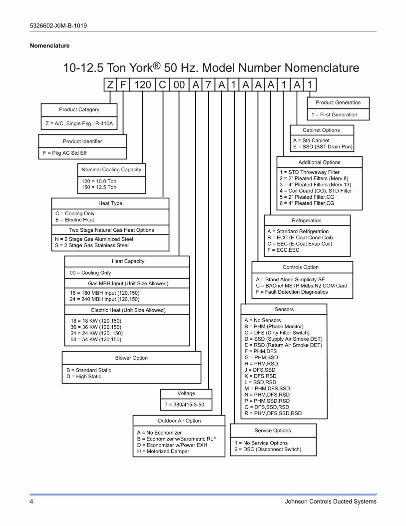
Nomenclature
Z F 120 C A 7 A 1 A 1A A 1
Product Category
Z = A/C, Single Pkg., R-410A
B = Standard StaticD = High Static
Blower Option
Product Generation
1 = First Generation
C = Cooling OnlyE = Electric Heat
Heat Type
18 = 18 KW (120,150)36 = 36 KW (120,150)24 = 24 KW (120, 150)54 = 54 KW (120,150)
18 = 180 MBH Input (120,150)24 = 240 MBH Input (120,150)
Heat Capacity
Nominal Cooling Capacity
120 = 10.0 Ton150 = 12.5 Ton
Product Identifier
F = Pkg AC Std Eff
Voltage
7 = 380/415-3-50
Additional Options
1 = STD Throwaway Filter2 = 2" Pleated Filters (Merv 8)3 = 4" Pleated Filters (Merv 13)4 = Coil Guard (CG), STD Filter5 = 2" Pleated Filter,CG6 = 4" Pleated Filter,CG
A = Std CabinetE = SSD (SST Drain Pan)
A = No EconomizerB = Economizer w/Barometric RLFD = Economizer w/Power EXHH = Motorized Damper
Outdoor Air Option
1 = No Service Options2 = DSC (Disconnect Switch)
A = No SensorsB = PHM (Phase Monitor)C = DFS (Dirty Filter Switch)D = SSD (Supply Air Smoke DET)E = RSD (Return Air Smoke DET)F = PHM,DFSG = PHM,SSDH = PHM,RSDJ = DFS,SSDK = DFS,RSDL = SSD,RSDM = PHM,DFS,SSDN = PHM,DFS,RSDP = PHM,SSD,RSDQ = DFS,SSD,RSDR = PHM,DFS,SSD,RSD
Refrigeration
A = Standard RefrigerationB = ECC (E-Coat Cond Coil)C = EEC (E-Coat Evap Coil)F = ECC,EEC
Service Options
A = Stand Alone Simplicity SEC = BACnet MSTP,Mdbs,N2 COM CardF = Fault Detection Diagnostics
Controls Option
10-12.5 Ton York® 50 Hz. Model Number Nomenclature
Two Stage Natural Gas Heat Options
N = 2 Stage Gas Aluminized SteelS = 2 Stage Gas Stainless Steel
00
00 = Cooling Only
Gas MBH Input (Unit Size Allowed)
Electric Heat (Unit Size Allowed) Sensors
A
Cabinet Options
5326602-XIM-B-1019
Johnson Controls Ducted Systems 5
Installation
Installation Safety Information
Read these instructions before continuing this appliance installation. This is an outdoor combination heating and cooling unit. The installer must assure that these instructions are made available to the consumer and with instructions to retain them for future reference.
1. Refer to the unit rating plate for the approved type of gas for this product.
2. Install this unit only in a location and position as specified on Page 7 of these instructions.
3. Never test for gas leaks with an open flame. Use commercially available soap solution made specifically for the detection of leaks when checking all connections, as specified on Pages 5, 26, 27 and 51 of these instructions.
4. Always install furnace to operate within the furnace's intended temperature-rise range with the duct system and within the allowable external static pressure range, as specified on the unit name/rating plate, specified on Page 53 of these instructions.
5. This equipment is not to be used for temporary heating of buildings or structures under construction.
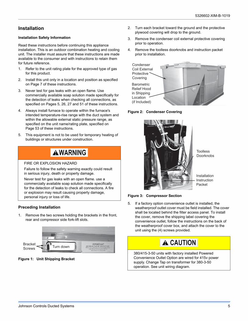
Preceding Installation
1. Remove the two screws holding the brackets in the front, rear and compressor side fork-lift slots.
Figure 1: Unit Shipping Bracket
2. Turn each bracket toward the ground and the protective plywood covering will drop to the ground.
3. Remove the condenser coil external protective covering prior to operation.
4. Remove the toolless doorknobs and instruction packet prior to installation.
Figure 2: Condenser Covering
Figure 3: Compressor Section
5. If a factory option convenience outlet is installed, the weatherproof outlet cover must be field installed. The cover shall be located behind the filter access panel. To install the cover, remove the shipping label covering the convenience outlet, follow the instructions on the back of the weatherproof cover box, and attach the cover to the unit using the (4) screws provided.
FIRE OR EXPLOSION HAZARD
Failure to follow the safety warning exactly could result in serious injury, death or property damage.
Never test for gas leaks with an open flame. use a commercially available soap solution made specifically for the detection of leaks to check all connections. A fire or explosion may result causing property damage, personal injury or loss of life.
BracketScrews Turn down
380/415-3-50 units with factory installed Powered Convenience Outlet Option are wired for 415v power supply. Change Tap on transformer for 380-3-50 operation. See unit wiring diagram.
Condenser Coil External Protective Covering
Barometric Relief Hood in Shipping Location(if Included)
Toolless Doorknobs
Installation Instruction Packet

5326602-XIM-B-1019
6 Johnson Controls Ducted Systems
Limitations
These units must be installed in accordance with all national and local safety codes. If no local codes apply, installation must conform with the appropriate national codes. Units are designed to meet National Safety Codes Standards. If components are to be added to a unit to meet local codes, they are to be installed at the dealer’s and/or the customer’s expense. See Table 1 for application limitations.
After installation, gas fired units must be adjusted to obtain a temperature rise within the range specified on the unit rating plate.
Figure 4: Component Location (ZF120 Shown)
The Smart Equipment™ control board used in this product will effectively operate the cooling system down to 0°F when this product is applied in a comfort cooling application for people. An economizer is typically included in this type of application. When applying this product for process cooling applications (computer rooms, switchgear, etc.), please reference applications bulletin AE-011-07 or call the applications department for Unitary Products @ 1-877-UPG-SERV for guidance. Additional accessories may be needed for stable operation at temperatures below 30° F.
Roof curbs in eight- and fourteen-inch heights. Roof curbs for transitioning from York Sunline™ footprint to the ZF Series footprints are also available (field installed accessory)
Base rails w/forklift slots (three sides) and lifting holes
Compressor #2 access (high- efficiency compressor)
Dual stage cooling for maximum comfort
Second model nameplate inside hinged access panel
Terminal block for hi-voltage connection
Smart Equipment™ control board w/screw connector for T-stat wiring and network connections
Disconnect location (optional disconnect switch)
Filter Access(2” or 4” filter options) Filter drier
(solid core)
Slide-out motor and blower assembly for easy adjustment and service
Belt-drive blower motor
Power ventor motor20-gauge alumi-nized steel tubularheat exchanger forlong life (stainlesssteel option)
Two-stage gas heating to maintain warm, comfortable temperature
Ignition control board for safe and efficient operation
Compressor #1 access (high-efficiency compressor) Toolless
door latch
Side entry power and control wiring knockouts
Slide-out drain panwith 3/4” NPT,female connection
ZF Series utilize Micro-ChannelAluminum Tube/Aluminum FinCondenser

5326602-XIM-B-1019
Johnson Controls Ducted Systems 7
Location
Use the following guidelines to select a suitable location for these units:
1. Unit is designed for outdoor installation only.
2. Condenser coils must have an unlimited supply of air. Where a choice of location is possible, position the unit on either north or east side of building.
3. Suitable for mounting on roof curb.
4. For ground level installation, use a level concrete slab with a minimum thickness of 4 inches. The length and width should be at least 6 inches greater than the unit base rails. Do not tie slab to the building foundation.
5. Roof structures must be able to support the weight of the unit and its options/accessories. Unit must be installed on a solid, level roof curb or appropriate angle iron frame.
6. Maintain level tolerance to 1/2” across the entire width and length of unit.
Clearances
All units require particular clearances for proper operation and service. Installer must make provisions for adequate combustion and ventilation air in accordance with section 5.3 of Air for Combustion and Ventilation of the National Fuel Gas Code, ANSI Z223.1 – Latest Edition (in U.S.A.), or Sections 7.2, 7.3, or 7.4 of Gas Installation Codes, CSA-B149.1 (in Canada) - Latest Edition, and/or applicable provisions of the local building
codes. Refer to Table 8 for clearances required for combustible construction, servicing, and proper unit operation.
Rigging And Handling
Exercise care when moving the unit. Do not remove any packaging until the unit is near the place of installation. Rig the unit by attaching chain or cable slings to the lifting holes provided in the base rails. Spreader bars, whose length exceeds the largest dimension across the unit, MUST be used across the top of the unit.
Units may be moved or lifted with a forklift. Slotted openings in the base rails are provided for this purpose.
LENGTH OF FORKS MUST BE A MINIMUM OF 60 INCHES.
Table 1: ZF120-150 Unit Limitations
Size(Tons/KW)
Model Unit Voltage
Unit Limitations
Applied Voltage Outdoor DB Temp
Min Max Max (°F/°C)
120(10/35)
ZF 380/415-3-50 342 457 125/52
150(12.5/44)
ZF 380/415-3-50 342 457 125/52
Excessive exposure of this furnace to contaminated combustion air may result in equipment damage or personal injury. Typical contaminates include: permanent wave solution, chlorinated waxes and cleaners, chlorine based swimming pool chemicals, water softening chemicals, carbon tetrachloride, Halogen type refrigerants, cleaning solvents (e.g. perchloroethylene), printing inks, paint removers, varnishes, hydrochloric acid, cements and glues, antistatic fabric softeners for clothes dryers, masonry acid washing materials.
Do not permit overhanging structures or shrubs to obstruct condenser air discharge outlet, combustion air inlet or vent outlets.
If a unit is to be installed on a roof curb other than a York® roof curb, gasketing must be applied to all surfaces that come in contact with the unit underside.
Before lifting, make sure the unit weight is distributed equally on the rigging cables so it will lift evenly.
All panels must be secured in place when the unit is lifted.
The condenser coils should be protected from rigging cable damage with plywood or other suitable material.

5326602-XIM-B-1019
8 Johnson Controls Ducted Systems
Figure 5: Unit 4 Point Load WeightFigure 6: Unit 6 Point Load Weight
Figure 7: Center of Gravity
D
A
CBLEFTFRONT
D
A
C
BE
F
LEFTFRONT
X Y
LEFTFRONT
Table 2: Weights and Dimensions Imperial
Size (Tons)
ModelWeight (lbs.)
Center of Gravity (in.)
4 Point Load Location (lbs.) 6 Point Load Location (lbs.)
Shipping Operating X Y A B C D A B C D E F
120(10)
ZF 1065 1060 38 24 247 184 268 360 173 141 117 171 206 253
150(12.5)
ZF 1258 1253 47 25 251 280 381 341 164 176 190 259 240 223
Table 3: Weights and Dimensions Metric
Size(KW)
ModelWeight (kg.)
Center of Gravity (mm)
4 Point Load Location (kg.) 6 Point Load Location (kg.)
Shipping Operating X Y A B C D A B C D E F
120(35)
ZF 483 480 965.2 609.7 112 83.5 121.6 163.3 78.5 64 53.1 77.6 93.4 114.8
150(44)
ZF 571 568 1193.8 635 113.9 127 172.8 154.7 74.4 79.8 86.2 117.5 108.9 101.2

5326602-XIM-B-1019
Johnson Controls Ducted Systems 9
Figure 8: ZF120 Unit Dimensions
Table 4: ZF120-150 Unit Accessory Weights Imperial
Unit AccessoryWeight (lbs.)
Shipping OperatingEconomizer 90 85
Power Exhaust 40 35Electric Heat1
1. Weight given is for the maximum heater size available (54KW).
49 49Gas Heat2
2. Weight given is for the maximum number of tube heat exchangers available (8 tube).
110 110
Table 5: ZF120-150 Unit Accessory Weights Metric
Unit AccessoryWeight (kg.)
Shipping OperatingEconomizer 40.8 38.6
Power Exhaust 18.1 15.9Electric Heat1
1. Weight given is for the maximum heater size available (54KW).
22.2 22.2Gas Heat2
2. Weight given is for the maximum number of tube heat exchangers available (8 tube).
49.9 49.9
LEFT
A
59.00
CD
E
F
4.19
27.31
89.00
21.19
11.38
15.38
59.00
15.38
29.69
15.25
FRONT
SEE DETAIL BFOR DRAIN LOCATION
SEE DETAIL A FOR GAS INLET
B
2X Ø 24.38(619)
(754)
(387)
(391)
(1499)
(391)
(1499)(538)
(2261)
(106)
(694)
(289)
NOTE: (XXX) Indicates Millimeters

5326602-XIM-B-1019
10 Johnson Controls Ducted Systems
Figure 9: ZF150 Unit Dimensions
LEFT
59.00
A
CD
E
F
4.19
27.31
89.00
21.19
FRONT
SEE DETAIL BFOR DRAIN LOCATION
11.38
SEE DETAIL A FOR GAS INLET
B
29.95 30.11
14.92
59.00
14.92
14.92
45.64
4X Ø 24.38
NOTE: (XXX) Indicates Millimeters
(619)
(1159)
(379)
(379)
(1499)
(379)
(765)(761)
(1499)
(106)
(694) (538)
(2261)
(289)
Table 6: ZF120-150 Unit Physical Dimensions Imperial
Unit Model NumberDimension (in.)
A B C D E F120 50 3/4 89 30 3/16 24 3/16 17 3/16 6 3/16150 50 3/4 119 1/2 30 3/16 24 3/16 17 3/16 6 3/16
Table 7: ZF120-150 Unit Physical Dimensions Metric
Unit Model NumberDimension (mm)
A B C D E F120 1289 2261 767 614 437 157 150 1289 3035 767 614 437 157

5326602-XIM-B-1019
Johnson Controls Ducted Systems 11
Detail A
Detail B
Table 8: ZF120-150 Unit Clearances Imperial
Direction Distance (in.) Direction Distance (in.)Top1
1. Units must be installed outdoors. Over hanging structure or shrubs should not obscure condenser air discharge outlet.
72 Right 12Front 36 Left 36Rear 36 Bottom2
2. Units may be installed on combustible floors made from wood or class A, B or C roof covering materials.
0
Table 9: ZF120-150 Unit Clearances Metric
Direction Distance (mm) Direction Distance (mm)Top1
1. Units must be installed outdoors. Over hanging structure or shrubs should not obscure condenser air discharge outlet.
1829 Right 305Front 914 Left 914Rear 914 Bottom2
2. Units may be installed on combustible floors made from wood or class A, B or C roof covering materials.
0
42”/1067mm CABINET
Ø 3.126
Ø 2.000
3.184
4.727
7.705
14.594
Gas Pipe Inlet
Gas Exhaust Vent
50 3/4”/1289mm CABINET
Ø 3.126
Ø 2.000
3.184
4.737
7.715
17.541
Gas Pipe Inlet
Gas Exhaust Vent
(81)
(51)
(587)
(120)
(371)
(196)
NOTE: (XXX) Indicates Millimeters
5-3/8
3/4” FPT
(137)
(19.05)
NOTE: (XXX) Indicates Millimeters

5326602-XIM-B-1019
12 Johnson Controls Ducted Systems
TOP VIEW
Figure 10: ZF120-150 Unit Bottom Duct Openings
Bottom condensate drain
Bottom gassupply entry
FRONT
RETURNAIR
SUPPLYAIR
RIGHTLEFT
20 1/8 19 1/8 17 1/8
6 13/16
6 13/16
32 11/16
14 1/2
16 3/8
18 1/16
25 9/16
12 5/16
27 1/2 24
2118
89(2261)
(830)
(173)
(173)
(690)
(457)
(610)
(533)
(511) (486) (435)
(368)
(416)
(459)
(649)
(313)
NOTE: (XXX) Indicates Millimeters
Ø 2.469
3X Ø 0.875
Bottom power, controland convenience outlet
wiring entry
(22)
(63)

5326602-XIM-B-1019
Johnson Controls Ducted Systems 13
Figure 11: ZF120-150 Unit Electrical Entry
Figure 12: ZF120 Unit Side Duct Openings
Disconnect Swith Cover
Power Entry Ø 2-1/2
Control Entry Ø 7/8
Power Entry Ø 2-1/2
Convenience Outlet Cover
Convenience Outlet Power Entry Ø 7/8 FRONT
(64)
(22)
(64)
(22)
D o t P l u g s
5 - 5 /3 2
3 1 - 1 1 /1 6
2 - 3 1 /3 2
1 8 - 1 /4
ReturnAir
Supply Air
A
B
C
D
(464)
(75)
(805)
(131)
NOTE: (XXX) Indicates Millimeters

5326602-XIM-B-1019
14 Johnson Controls Ducted Systems
Figure 13: ZF150 Unit Side Duct Openings
Figure 14: ZF120 - 150 Unit Left Duct Opening
Dot Plugs
2-7/85-5/32
D
C31-5/8
18-1/4
B
A
(464)
(75)
(805)
(131)
NOTE: (XXX) Indicates Millimeters
Table 10: ZF Side Duct Dimensions Imperial
Unit Model NumberDimension (in.)
A B C D
120 28 1/4 18 1/16 28 1/4 18 1/4
150 28 1/4 18 1/16 28 1/4 18 1/4
Table 11: ZF Side Duct Dimensions Metric
Unit Model NumberDimension (mm)
A B C D
120 718 459 718 464
150 718 459 718 464

5326602-XIM-B-1019
Johnson Controls Ducted Systems 15
Figure 15: ZF120-150 Roof Curb
Figure 16: ZF120-150 Transition Roof Curb
Ductwork
Ductwork should be designed and sized according to the methods in Manual D of the Air Conditioning Contractors of America (ACCA) or as recommended by any other recognized authority such as ASHRAE or SMACNA.
A closed return duct system should be used. This will not preclude use of economizers or outdoor fresh air intake. The supply and return air duct connections at the unit should be made with flexible joints to minimize noise.
The supply and return air duct systems should be designed for the CFM and static pressure requirements of the job. They
� � � � � �� � � �
� �� � �
� �� � � �
� � � � � � � � �
� � � �
� � � � � �� � �
� � � � � � � � � � � � � � � � � � � �� � � � � � � � � � � � � � � � � �
� � � � � � � � � � � � � � � � � � � �� � � � � � � � � � � � � � � � �
� � � �
� � ! " �
� � � � � �
� � � � � �
� �� � � �
� � � � # � $ $ $ � � � � � � � � � �� � � � � � � � � � � � �� � � � � � � � � � �
� %� � � �
� � � �
� �
� � � � � � & % �
& %� � � & �
� � � � � �� � � �
� � � � � �� � � �
% � � � %� � � �
� & � � � %� � � � �
� �� � � �
� �� � �
%� � � � �
� � � � � � � � � � �
� � � � �� � �
� � � �
� � ! " �
� � � � � �
� � � � � �

5326602-XIM-B-1019
16 Johnson Controls Ducted Systems
should NOT be sized to match the dimensions of the duct connections on the unit.
Refer to Figure 10 for bottom air duct openings. Refer to Figures 12, 13 and Table 10 for side air duct openings.
Duct Covers
Units are shipped with the side duct openings covered and a covering over the bottom of the unit. For bottom duct application, no duct cover changes are necessary. For side duct application, remove the side duct covers and install over the bottom duct openings. The panels removed from the side duct connections are designed to be reused by securing each panel to its respective downflow opening. But keep in mind that the supply panel is installed with the painted surface UP, facing the heat exchanger, while the return panel is installed with the painted surface DOWN, facing the downflow duct opening. The supply panel is secured with the bracket (already in place from the factory) and two screws. It’s a snug fit for the panel when sliding it between the heat exchanger and unit bottom, but there is room. The return panel is secured with four screws.
Figure 17: Side Panels With Hole Plugs
NOTE: Orientation. Panel is “insulation” side up.
Figure 18: Return Downflow Plenum With Panel
Figure 19: Discharge Panel In Place
Side Panels
Units are shipped with side panels to cover the area where an economizer or motorized damper may be installed. These panels must be saved and used as tops for the Economizer rain hoods (See Figure 19)
Figure 20: Save Side Panels For Economizer Hood Tops
Condensate Drain
The side condensate drain is reversible and maybe re-oriented to the rear of the cabinet to facilitate condensate piping. A condensate drain connection is available through the base pan for piping inside the roof curb. Trap the connection per Figure 21. The trap and drain lines should be protected from freezing.
Plumbing must conform to local codes. Use a sealing compound on male pipe threads. Install condensate drain line from the 3/4 inch NPT female connection on the unit to an open drain.
When fastening ductwork to side duct flanges on unit, insert screws through duct flanges only. DO NOT insert screws through casing. Outdoor ductwork must be insulated and water-proofed.

5326602-XIM-B-1019
Johnson Controls Ducted Systems 17
Figure 21: Condensate Drain
Compressors
The scroll compressor used in this product is specifically designed to operate with R-410A Refrigerant and cannot be interchanged.
The compressor also uses a polyolester (POE oil), Mobil 3MA POE. This oil is extremely hygroscopic, meaning it absorbs water readily. POE oil can absorb 15 times as much water as other oils designed for HCFC and CFC refrigerants. Take all necessary precautions to avoid exposure of the oil to the atmosphere.
POE (polyolester) compressor lubricants are known to cause long term damage to some synthetic roofing materials.
Procedures which risk oil leakage include, but are not limited to, compressor replacement, repairing refrigerant leaks, replacing
refrigerant components such as filter drier, pressure switch, metering device or coil.
Units are shipped with compressor mountings which are factory-adjusted and ready for operation.
Filters
Two-inch filters are supplied with each unit. One-inch filters may be used with no modification to the filter racks. Filters must always be installed ahead of evaporator coil and must be kept clean or replaced with same size and type. Dirty filters reduce the capacity of the unit and result in frosted coils or safety shutdown. Refer to physical data tables, for the number and size of filters needed for the unit. The unit should not be operated without filters properly installed.
Power And Control Wiring
Field wiring to the unit, fuses, and disconnects must conform to provisions of National Electrical Code (NEC), ANSI/NFPA No. 70 – Latest Edition (in U.S.A.), current Canadian Electrical Code C221, and/or local ordinances. The unit must be electrically grounded in accordance with NEC and CEC as specified above and/or local codes.
Voltage tolerances which must be maintained at the compressor terminals during starting and running conditions are indicated on the unit Rating Plate and Table 1.
The internal wiring harnesses furnished with this unit are an integral part of the design certified unit. Field alteration to comply with electrical codes should not be required. If any of the wire supplied with the unit must be replaced, replacement wire must be of the type shown on the wiring diagram and the same minimum gauge as the replaced wire.
A disconnect must be utilized for these units. Factory installed disconnects are available. If installing a disconnect (field
This system uses R-410A Refrigerant which operates at higher pressures than R-22. No other refrigerant may be used in this system.
Do not leave the system open to the atmosphere. Unit damage could occur due to moisture being absorbed by the POE oil in the system. This type of oil is highly susceptible to moisture absorption
Exposure, even if immediately cleaned up, may cause embrittlement (leading to cracking) to occur in one year or more. When performing any service that may risk exposure of compressor oil to the roof, take precautions to protect roofing.
3" Minimum
Do not loosen compressor mounting bolts.
Make sure that panel latches are properly positioned on the unit to maintain an airtight seal.
380/415-3-50 units control transformers are factory wired for 415v power supply respectively. Change tap on transformer for 380-3-50 operation. See unit wiring diagram.

5326602-XIM-B-1019
18 Johnson Controls Ducted Systems
supplied or York International® supplied accessory), refer to Figure 4 for the recommended mounting location.
NOTE: Since not all local codes allow the mounting of a disconnect on the unit, please confirm compliance with local code before mounting a disconnect on the unit.
Electrical line must be sized properly to carry the load. USE COPPER CONDUCTORS ONLY. Each unit must be wired with a separate branch circuit fed directly from the meter panel and properly fused.
Refer to Figures 23, 24 and 24 for typical field wiring and to the appropriate unit wiring diagram mounted inside control doors for control circuit and power wiring information.
Power Wiring Detail
Units are factory wired for the voltage shown on the unit nameplate. Refer to Electrical Data Table 13 to size power wiring, fuses, and disconnect switch.
Power wiring is brought into the unit through the side of the unit or the basepan inside the curb.
Figure 22: Field Wiring Disconnect - Cooling Unit With/Without Electric Heat
Avoid damage to internal components if drilling holes for disconnect mounting.
When connecting electrical power and control wiring to the unit, water-proof connectors must be used so that water or moisture cannot be drawn into the unit during normal operation. The above water-proofing conditions will also apply when installing a field supplied disconnect switch.
THREEPHASE POWER SUPPLY
FACTORY OR FIELD SUPPLIED DISCONNECT
GROUND LUG
TERMINAL BLOCK TB1

5326602-XIM-B-1019
Johnson Controls Ducted Systems 19
Figure 23: Field Wiring Disconnect - Cooling Unit With Gas Heat
L1
T1
L2
T2 T3
L3
THREEPHASE POWER SUPPLY
FACTORY OR FIELD SUPPLIED DISCONNECT
GROUND LUG
CONTACTOR 1M

5326602-XIM-B-1019
20 Johnson Controls Ducted Systems
Thermostat Wiring
The thermostat should be located on an inside wall approximately 56 inch above the floor where it will not be subject to drafts, sun exposure or heat from electrical fixtures or appliances. Follow the manufacturer's instructions enclosed with thermostat for general installation procedure. Seven (7) color-coded, insulated wires should be used to connect the
thermostat to the unit. Refer to Table 12 for control wire sizing and maximum length.
Figure 24: Typical Electronic Thermostat Field Wiring
Table 12: Control Wire Sizes
Wire Size Maximum Length1
1. From the unit to the thermostat and back to the unit.
18 AWG 150 Feet
380/415-3-50 units control transformers are factory wired for415v power supply respectively. Change tap on transformer for 380-3-50 operation. See unit wiring diagram.
OCC
C
RC
G
Y2
Y1
W2
W1
X
R
THERMOSTATTERMINALS
CONTROL TERMINAL
BLOCK
TERMINALS ON A LIMITED NUMBER OF THERMOSTATS
1
4
3
1
2
4
Second stage ot required on single stage he g units.
Jumper is required if there is no Smoke Detector circuit.
Jumper is required for any co of R, RC, or RH.
5
5
OCC is an output from the thermostat to indicate the Occupied on.
X is an input to the thermostat to display Error Status condi ons.
3
W2Y1G
OCC
Y2
XR
SD-24C
W1
2
24V
C
24 VACClass 2
SD-24 Jumper Located on Harness
SmokeDetector
SD-R
24V Output
R
(If No Smoke Detector) (If Smoke Detector Is Used)
R~Occ Jumper:Smart Equipment Control boards come from thefactory with a jumper wire between R and OCCterminals on the thermostat terminal strip. Failureto remove this jumper will place the unit into the Occupied mode no matter what the occupancydemand is from the thermostat or EMS system.To allow Thermostat or EMS control of the Occupied mode for the unit, this jumper must be removed during commissioning.

5326602-XIM-B-1019
Johnson Controls Ducted Systems 21
Table 13: Electrical Data
ZF120 Standard Motor
Size(Tons)
Volt
Compressors (each) OD Fan Motors (each)
Supply Blower Motor
Pwr Exh
Motor Electric Heat Option
MCA1 (Amps)
MCA1 w/ Pwr Exh (Amps)
Max Fuse2/ Breaker3
Size (Amps)
Max Fuse2/ Breaker3
Size w/ Pwr Exh (Amps)RLA LRA MCC FLA FLA FLA Model KW Stages Amps
ZF120
380 8.0 67.1 12.5 1.6 4.3 2.2
None - - - 25.5 27.7 30 35
2TP04521850 11.3 2 17.2 26.8 29.6 30 35
2TP04522450 15.0 2 22.8 33.9 36.6 35 40
2TP04523650 21.3 2 32.4 45.8 48.6 50 50
2TP04525450 33.8 2 51.4 69.6 72.3 70 80
415 8.0 67.1 12.5 1.6 4.3 2.2
None - - - 25.5 27.7 30 35
2TP04521850 13.5 2 18.8 28.9 31.6 30 35
2TP04522450 17.9 2 24.9 36.5 39.3 40 40
2TP04523650 25.4 2 35.3 49.5 52.3 50 60
2TP04525450 40.4 2 56.2 75.6 78.4 80 80
1. Minimum Circuit Ampacity.2. Maximum Over current Protection per Standard UL 1995.3. Fuse or HACR circuit breaker size installed at factory or field installed.
ZF120-150 Hi Static Motor
Size(Tons)
Volt
Compressors (each) OD Fan Motors (each)
Supply Blower Motor
Pwr Exh Motor
Electric Heat OptionMCA1
(Amps)
1. Minimum Circuit Ampacity.
MCA1 w/ Pwr Exh (Amps)
Max Fuse2/
Breaker3 Size
(Amps)
2. Maximum Over current Protection per Standard UL 1995.3. Fuse or HACR circuit breaker size installed at factory or field installed.
Max Fuse2/ Breaker3 Size
w/ Pwr Exh (Amps)RLA LRA MCC FLA FLA FLA Model KW Stages Amps
ZF120
380 8.0 67.1 12.5 1.6 6.4 2.2
None - - - 27.6 29.8 35 35
2TP04521850 11.3 2 17.2 29.5 32.2 35 35
2TP04522450 15.0 2 22.8 36.5 39.2 40 40
2TP04523650 21.3 2 32.4 48.5 51.2 50 60
2TP04525450 33.8 2 51.4 72.2 74.9 80 80
415 8.0 67.1 12.5 1.6 6.4 2.2
None - - - 27.6 29.8 35 35
2TP04521850 13.5 2 18.8 31.5 34.2 35 35
2TP04522450 17.9 2 24.9 39.1 41.9 40 45
2TP04523650 25.4 2 35.3 52.2 54.9 60 60
2TP04525450 40.4 2 56.2 78.3 81.0 80 90
ZF150
380 11.2 75.0 17.5 1.6 6.4 2.2
None - - - 38.0 40.2 45 50
2TP04521850 11.3 2 17.2 38.0 40.2 45 50
2TP04522450 15.0 2 22.8 38.0 40.2 45 50
2TP04523650 21.3 2 32.4 48.5 51.2 50 60
2TP04525450 33.8 2 51.4 72.2 74.9 80 80
415 11.2 75.0 17.5 1.6 6.4 2.2
None - - - 38.0 40.2 45 50
2TP04521850 13.5 2 18.8 38.0 40.2 45 50
2TP04522450 17.9 2 24.9 39.1 41.9 45 50
2TP04523650 25.4 2 35.3 52.2 54.9 60 60
2TP04525450 40.4 2 56.2 78.3 81.0 80 90

5326602-XIM-B-1019
22 Johnson Controls Ducted Systems
Table 14: ZF120-150 Physical Data
ComponentModels
ZF120 ZF150
Nominal Tonnage 10 12.5
Brand YORK YORK
Country of Origin Made in USA Made in USA
Rated Voltage Range 380-415 Volts 380-415 Volts
Rated Frequency 50Hz 50Hz
Nominal CFM 4000 5000
Rated Cooling Capacity (T1) - BTUH 115322 151527
Rated Power Input (T1) - KW 10.05 12.72
Energy Efficiency Ratio (EER) (T1) - BTUH/W 11.48 11.91
Rated Cooling Capacity (T3) - BTUH 107070 130963
Rated Power Input (T3) - KW 12.44 15.61
Rated Current (T3) - AMPS 22.1 27.5
Energy Efficiency Ratio (EER) (T3) - BTUH/W 8.61 8.39
Refrigerant used R-410A R-410A
Refrigerant charge (lb-oz)
System 1 7-12 8-3
System 2 7-8 8-10
AHRI HEATING PERFORMANCE
Heating model N18 N24 N18 N24
Heat input (K Btu) 180 240 180 240
Heat output (K Btu) 144 192 144 192
AFUE % - - - -
Steady state efficiency (%) 80 80 80 80
No. burners 6 8 6 8
No. stages 21 21 21 21
Temperature Rise Range (ºF) 20-50 35-65 10-40 25-55
Gas Limit Setting (ºF) 195 160 195 160
Gas piping connection (in.) 3/4 3/4 3/4 3/4
DIMENSIONS (inches)
Length 89 119-1/2
Width 59 59
Height 50-3/4 50-3/4
OPERATING WT. (lbs.) 1060 1253
COMPRESSORS
Type Scroll Scroll
Quantity 2 2
Unit Capacity Steps (%) 50 / 100 50 / 100
CONDENSER COIL DATA
Face area (Sq. Ft.) 29.0 29.0
Rows 1 1
Fins per inch 23 23
Tube diameter (in.)/mm 1/25 1/25
Circuitry Type 2-pass Microchannel 2-pass Microchannel
EVAPORATOR COIL DATA
Face area (Sq. Ft.) 13.2 13.2

5326602-XIM-B-1019
Johnson Controls Ducted Systems 23
Rows 4 4
Fins per inch 15 15
Tube diameter 0.375 0.375
Circuitry Type Intertwined Intertwined
Refrigerant control TXV TXV
CONDENSER FAN DATA
Quantity of Fans 2 4
Fan diameter (Inch) 24 24
Type Prop Prop
Drive type Direct Direct
Quantity of motors 2 4
Motor HP each @ 50 Hz. 3/4 3/4
No. speeds 1 1
RPM @ 50 Hz. 9402 9402
Nominal total CFM 9500 13900
BELT DRIVE EVAP FAN DATA
Quantity 1 1
Fan Size (Inch) 15 x 15 15 x 15
Type Centrifugal Centrifugal
Motor Sheave 1VM50 1VP56 1VP56
Blower Sheave AK74 AK66 BK72
Belt A54 A56 BX56
Motor HP each @ 50 Hz. 2 4 4
RPM @ 50 Hz. 14253 14553 14553
Frame size 56 184T 184T
FILTERS
Quantity - Size4 - (24 x 20 x 2)4, 5 4 - (24 x 20 x 2)4, 5
4 - (24 x 20 x 4)6 4 - (24 x 20 x 4)6
1. 1ST Stage 60% of 2nd Stage2. 1110 RPM 60 Hz.3. 1725 RPM 60 Hz.4. 2 In. Throwaway, Standard, MERV (Minimum Efficiency Reporting Value) 35. 2 In. Pleated, Optional, MERV 86. 4 In. Pleated, Optional, MERV 13
Table 14: ZF120-150 Physical Data (Continued)
ComponentModels
ZF120 ZF150
Nominal Tonnage 10 12.5

5326602-XIM-B-1019
24 Johnson Controls Ducted Systems
Optional Electric Heat
The factory-installed heaters are wired for single point power supply. Power supply need only be brought into the single point terminal block.
These CSA approved heaters are located within the central compartment of the unit with the heater elements extending in to the supply air chamber.
Fuses are supplied, where required, by the factory. Some kW sizes require fuses and others do not. refer to Tables 15 and 16 for minimum CFM limitations and to Table 13 for electrical data.
Table 15: Electric Heat Minimum Supply Air Imperial
Size(Tons)
Model Voltage
Minimum Supply Air (CFM)
Heater kW
18 24 36 54
120(10)
ZF 380/415-3-50 3000 3000 3000 3500
150(12.5)
ZF 380/415-3-50 3750 3750 3750 3750
Table 16: Electric Heat Minimum Supply Air Metric
Size(KW)
Model Voltage
Minimum Supply Air (C3S)
Heater kW
18 24 36 54
120(35)
ZF 380/415-3-50 1.42 1.42 1.42 1.42
150(44)
ZF 380/415-3-50 1.76 1.76 1.76 1.76

5326602-XIM-B-1019
Johnson Controls Ducted Systems 25
Optional Gas Heat
These gas-fired heaters have aluminized-steel or optional stainless steel, tubular heat exchangers with spark ignition.
Gas Piping
Proper sizing of gas piping depends on the cubic feet per hour of gas flow required, specific gravity of the gas and the length of run. "National Fuel Gas Code" Z223.1 (in U.S.A.) or the current Gas Installation Codes CSA-B149.1 (in Canada) should be followed in all cases unless superseded by local codes or gas utility requirements. Refer to the Pipe Sizing Table 20. The heating value of the gas may differ with locality. The value should be checked with the local gas utility.
Figure 25: Side Entry Gas Piping
Figure 26: Bottom Entry Gas Piping
NOTE: Maximum capacity of pipe in cubic feet of gas per hour
based upon a pressure drop of 0.3 inch W.C. and 0.6 specific gravity gas.
OPTIONAL COIL GUARDSHOWN
OPTIONALCOIL GUARDSHOWN
Table 17: Gas Heat Minimum Supply Air Imperial
Size(Ton)
ModelHeatSize
Supply Air (CFM)
Cooling Heating
Min Max Min Max
120(10)
ZFN18 3000 5000 3000 5000
N24 3000 5000 3000 5000
150 (12.5)
ZFN18 3750 6250 3750 6250
N24 3750 6250 3750 6250
Table 18: Gas Heat Minimum Supply Air Metric
Size(KW)
ModelHeatSize
Supply Air (M3S)
Cooling Heating
Min Max Min Max
120(35)
ZFN18 1.42 2.36 1.42 2.36
N24 1.42 2.36 1.42 2.36
150(44)
ZFN18 1.76 2.95 1.76 2.95
N24 1.76 2.95 1.76 2.95

5326602-XIM-B-1019
26 Johnson Controls Ducted Systems
NOTE: There may be a local gas utility requirement specifying a minimum diameter for gas piping. All units require a 3/4 inch pipe connection at the entrance fitting. Line should not be sized smaller than the entrance fitting size.
Gas Connection
The gas supply line can be routed within the space and roof curb, exiting through the unit’s basepan. Refer to Figures 8 and 9 for the gas piping inlet location. Typical supply piping arrangements are shown in Figures 25 and 26. All pipe nipples, fittings, and the gas cock are field supplied or may be purchased in UP accessory kit #1GP0405.
Gas piping recommendations:
1. A drip leg and a ground joint union must be installed in the gas piping.
2. Where required by local codes, a manual shut-off valve must be installed outside of the unit.
3. Use wrought iron or steel pipe for all gas lines. Pipe dope should be applied sparingly to male threads only.
4. All piping should be cleaned of dirt and scale by hammering on the outside of the pipe and blowing out loose particles. Before initial start-up, be sure that all gas lines external to the unit have been purged of air.
5. The gas supply should be a separate line and installed in accordance with all safety codes as prescribed under “Limitations”.
6. A 1/8-inch NPT plugged tapping, accessible for test gage connection, must be installed immediately upstream of the gas supply connection to the unit.
7. After the gas connections have been completed, open the main shut-off valve admitting normal gas pressure to the mains. Check all joints for leaks with soap solution or other material suitable for the purpose. NEVER USE A FLAME.
LP Units, Tanks And Piping
All gas heat units are shipped from the factory equipped for natural gas use only. The unit may be converted in the field for use with LP gas with accessory kit model number 1NP0442.
All LP gas equipment must conform to the safety standards of the National Fire Protection Association.
Table 19: Gas Pipe Sizing - Capacity of Pipe
Length of Pipe ft. (m)
Nominal Iron Pipe Size
3/4 in. 1 in. 1-1/4 in.
10 (3) 278 (7.8) 520 (14.7) 1050 (29.7)
20 (6) 190 (5.3) 350 (9.9) 730 (20.6)
30 (9.1) 152 (4.3) 285 (8) 590 (16.7)
40 (12.1) 130 (3.6) 245 (6.9) 500 (14.1)
50 (15.2) 115 (3.2) 215 (6) 440 (12.4)
60 (18.2) 105 (2.9) 195 (5.5) 400 (12.4)
70 (21.3) 96 (2.7) 180 (5) 370 (10.4)
80 (24.3) 90 (2.5) 170 (4.8) 350 (9.9)
90 (27.4) 84 (2.3) 160 (4.5) 320 (9)
100 (30.4) 79 (2.2) 150 (4.2) 305 (8.6)
Natural gas may contain some propane. Propane is an excellent solvent and will quickly dissolve white lead and most standard commercial compounds. A special pipe dope must be used when assembling wrought iron or steel pipe. Shellac based compounds such as Gaskolac or Stalastic, and compounds such as Rectorseal #5, Clydes’s or John Crane may be used.
FIRE OR EXPLOSION HAZARD
Failure to follow the safety warning exactly could result in serious injury, death or property damage.
Never test for gas leaks with an open flame. use a commercially available soap solution made specifically for the detection of leaks to check all connections. A fire or explosion may result causing property damage, personal injury or loss of life.
The furnace and its individual shut-off valve must be disconnected from the gas supply piping system during any pressure testing at pressures in excess of 1/2 PSIG.
Pressures greater than 1/2 PSIG will cause gas valve damage resulting in a hazardous condition. If it is subjected to a pressure greater than 1/2 PSIG, the gas valve must be replaced.
The furnace must be isolated from the gas supply piping system by closing its individual manual shut-off valve during any pressure testing of the gas supply piping system at test pressures equal to or less than 1/2 PSIG.
Threaded joints should be coated with a sealing compound that is resistant to the action of liquefied petroleum gases. Do not use Teflon tape.

5326602-XIM-B-1019
Johnson Controls Ducted Systems 27
For satisfactory operation, LP gas pressure must be 10.5 inch W.C. at the unit under full load. Maintaining proper gas pressure depends on three main factors:
1. The vaporization rate which depends on the temperature of the liquid and the “wetted surface” area of the container(s).
2. The proper pressure regulation. (Two-stage regulation is recommended).
3. The pressure drop in the lines between regulators and between the second stage regulator and the appliance. Pipe size required will depend on the length of the pipe run and the total load of all appliances.
Complete information regarding tank sizing for vaporization, recommended regulator settings, and pipe sizing is available from most regulator manufacturers and LP gas suppliers.
Check all connections for leaks when piping is completed using a soap solution. NEVER USE A FLAME.
Vent And Combustion Air
Venting slots in the heating compartment access panel remove the need for a combustion air hood. The gas heat flue exhaust is routed through factory installed exhaust piping with screen. If necessary, a flue exhaust extension may be installed at the point of installation.
Options/Accessories
Electric Heat
Electric heaters are available as factory-installed options or field-installed accessories. Refer to electric heat instructions for installation. These heaters mount in the heat compartment with the heating elements extending into the supply air chamber. All
electric heaters are fused and intended for use with single point power supply.
Smoke Detectors
The factory-installed smoke detector will shut down operation of the unit by interrupting power to the UCB when smoke is detected within its mounting compartment. The smoke detector option is available for both supply and/or return air configura-tions. Be aware that the supply air configuration has the sensor component mounted in the blower section, with its control mod-ule mounted in the return air compartment.
The detector must be tested and maintained on a regular basis according to NFPA 72 requirements and cleaned at least once a year. For specific troubleshooting and maintenance procedures, please refer to the smoke detector's installation instructions which accompanies the unit.
Motorized Outdoor Damper
The Motorized Outdoor Damper can be a factory installed option or a field installed accessory. If factory installed, refer to the instructions included with the outdoor air hood to complete
LP gas is an excellent solvent and will quickly dissolve white lead and most standard commercial compounds. A special pipe dope must be used when assembling wrought iron or steel pipe for LP. Shellac base compounds such as Gaskolac or Stalastic, and compounds such as Rectorseal #5, Clyde’s, or John Crane may be used.
FIRE OR EXPLOSION HAZARD
Failure to follow the safety warning exactly could result in serious injury, death or property damage.
Never test for gas leaks with an open flame. use a commercially available soap solution made specifically for the detection of leaks to check all connections. A fire or explosion may result causing property damage, personal injury or loss of life.
The use of duct smoke detectors have specific limitations as established by the National Fire Protection Association. Duct smoke detectors are; NOT a substitute for an open area smoke detector, NOT a substitute for early warning detection, and NOT a replacement for a building's regular fire detection system. Refer to NFPA Code 72 and Standard 90A for additional information.
Factory-installed smoke detectors may be subjected to extreme temperatures during "off" times due to outside air infiltration. These smoke detectors have an operational limit of -4°F to 158°F. Smoke detectors installed in areas that could be outside this range will have to be relocated to prevent false alarms.
To assure adequate airflow reaches the smoke detector's sensor, make sure that the holes of the sampling tube face into the air stream, and that the far-end of the sampling tube is sealed with the plastic end cap.
In addition, the unit's supply airflow must be adjusted to provide a pressure differential across the smoke detector's sampling and exhaust ports of at least 0.01 inches of water and no more than 1.11 inches of water, as measured by a manometer.
5326602-XIM-B-1019
28 Johnson Controls Ducted Systems
the assembly. Field installed Motorized Outdoor Damper accessories include complete instructions for installation.
Economizer
The Economizer can be a factory installed option or a field installed accessory. If factory installed, refer to the instructions included with the outdoor air hood to complete the assembly. Field installed Economizer accessories include complete instructions for installation.
There are two Economizer options:
1. Down Flow, End Return Horizontal applications which include Fresh Air Hood, Exhaust Hood with Barometric Relief.
2. Horizontal Flow application (Field Installed Kit Only) that requires the purchase of a barometric relief hood.
NOTE: With the Down Flow, End Return Horizontal application it is required to save the two Side Panels for the economizer hood tops (See Figure 20).
Power Exhaust
The Power Exhaust can be a factory installed option or a field installed accessory. If factory installed, refer to the instructions included with the outdoor air hood to complete the assembly. Field installed Power Exhaust accessories include complete instructions for installation.
The Power Exhaust factory installed option is for Down Flow application only.
There are two field installed Power Exhaust accessories:
1. Down Flow application.
2. Horizontal Flow application that requires the purchase of a barometric relief hood.
Rain Hood
All of the hood components, including the filters, the gasketing and the hardware for assembling, are packaged and located between the condenser coil section and the main unit cabinet, if the unit has factory installed options. If field installed accessories are being installed all parts necessary for the installation comes in the accessory.
Optional Hot Gas Bypass (HGBP)
To allow for low cooling load operation, a direct-acting, pressure-modulating bypass control valve installed on the system #1 discharge line is used to divert high temperature, high pressure refrigerant around the TXV in order to maintain a desired minimum evaporator pressure.
The opening pressure of the bypass valve is adjustable between 95 and 115 psig with a factory-setting of 105 psig. HGBP is optional with CV units.
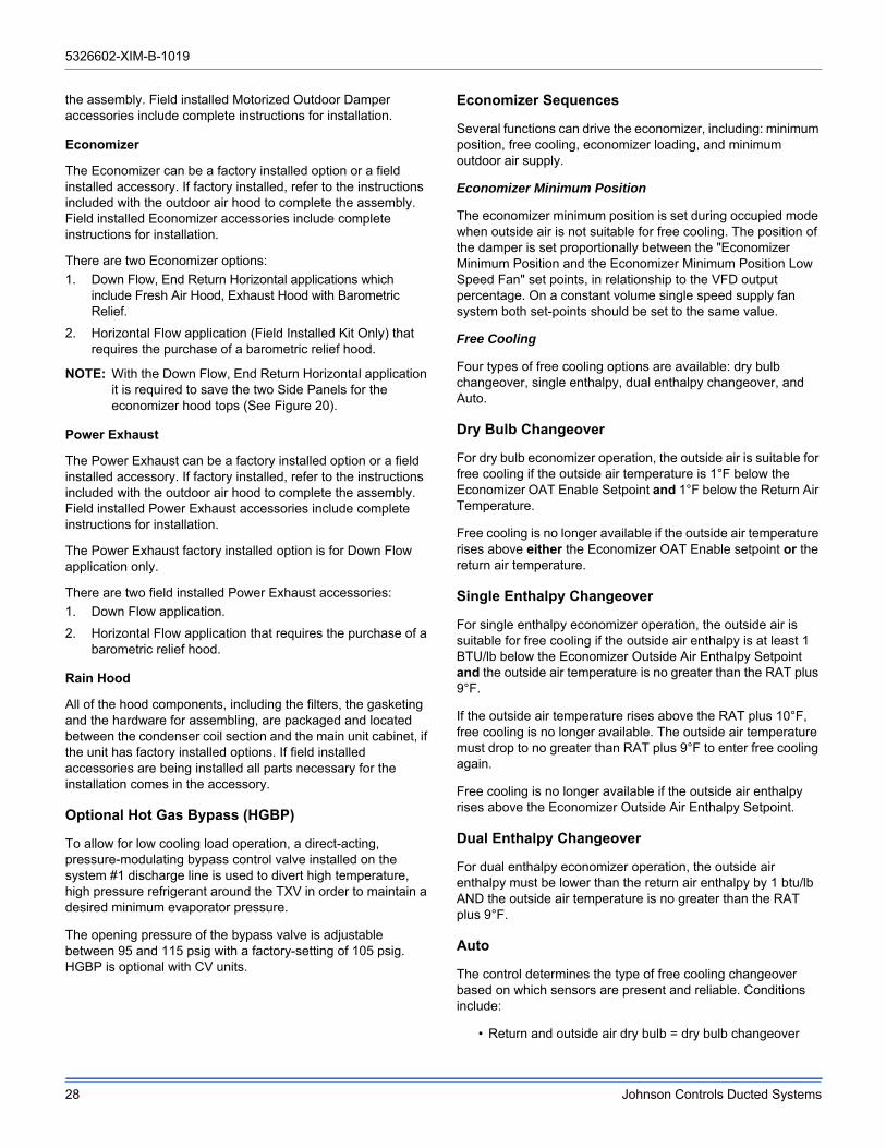
Economizer Sequences
Several functions can drive the economizer, including: minimum position, free cooling, economizer loading, and minimum outdoor air supply.
Economizer Minimum Position
The economizer minimum position is set during occupied mode when outside air is not suitable for free cooling. The position of the damper is set proportionally between the "Economizer Minimum Position and the Economizer Minimum Position Low Speed Fan" set points, in relationship to the VFD output percentage. On a constant volume single speed supply fan system both set-points should be set to the same value.
Free Cooling
Four types of free cooling options are available: dry bulb changeover, single enthalpy, dual enthalpy changeover, and Auto.
Dry Bulb Changeover
For dry bulb economizer operation, the outside air is suitable for free cooling if the outside air temperature is 1°F below the Economizer OAT Enable Setpoint and 1°F below the Return Air Temperature.
Free cooling is no longer available if the outside air temperature rises above either the Economizer OAT Enable setpoint or the return air temperature.
Single Enthalpy Changeover
For single enthalpy economizer operation, the outside air is suitable for free cooling if the outside air enthalpy is at least 1 BTU/lb below the Economizer Outside Air Enthalpy Setpoint and the outside air temperature is no greater than the RAT plus 9°F.
If the outside air temperature rises above the RAT plus 10°F, free cooling is no longer available. The outside air temperature must drop to no greater than RAT plus 9°F to enter free cooling again.
Free cooling is no longer available if the outside air enthalpy rises above the Economizer Outside Air Enthalpy Setpoint.
Dual Enthalpy Changeover
For dual enthalpy economizer operation, the outside air enthalpy must be lower than the return air enthalpy by 1 btu/lb AND the outside air temperature is no greater than the RAT plus 9°F.
Auto
The control determines the type of free cooling changeover based on which sensors are present and reliable. Conditions include:
• Return and outside air dry bulb = dry bulb changeover

5326602-XIM-B-1019
Johnson Controls Ducted Systems 29
• Return and outside air dry bulb and outside air humidity = single enthalpy
• Return and outside air dry bulb and return and outside air humidity = dual enthalpy
• If either the return or outside air dry bulb sensors are unreliable, free cooling is not available
Free Cooling Operation
When the control determines that the outside air is suitable, the first stage of cooling will always be free cooling.
Thermostat
In free cooling, with a thermostat input to Y1, the dampers modulate to control the supply air temperature to the Economizer Setpoint +/- 1°F (default 55°F).
If the thermostat provides an input to Y2 and the parameter Compressors Off in Free Cooling is turned OFF a compressor output energizes. The economizer dampers continue to modulate to control the supply air temperature to the Economizer Setpoint.
If the supply air temperature cannot be maintained within 5°F of the economizer setpoint, the first stage compressor (C1) will be turned on. Second stage compressor (C2) will be added as needed to keep the supply air temperature within the 5°F of the economizer setpoint.
Sensor
In free cooling, with a demand from the zone/return sensor for the first stage of cooling, the dampers modulate to control the supply air temperature to the Economizer Setpoint +/- 1°F.
If the economizer output is at 100% and the SAT is greater than the Economizer setpoint + 1°F, the control starts a 12-minute timer to energize a compressor output.
If at any time the economizer output drops below 100% the timer stops and resets when the economizer output returns to 100%.
Once a compressor output is turned ON, the economizer dampers continue to modulate to control the supply air temperature to the Economizer Setpoint.
At no time will a compressor output be turned ON if the economizer output is less than 100%, even if the differential between zone (or return) temperature and the current cooling setpoint is great enough to demand more than one stage of cooling.
If the economizer output goes to minimum position and the SAT is less than Economizer Setpoint -1°F, the control starts a 12-minute timer to de-energize a compressor output.
If at any time the economizer output goes above the minimum position the timer stops and resets when the economizer output returns to minimum position.
If the demand for cooling from the space/return is satisfied, the economizer output will modulate to minimum position and the compressor outputs will be de-energized as long as their minimum run timers have expired.
Power Exhaust
Setpoints
a. Economizer Enable ON
b. Power Exhaust Enable ON
c. Modulating Power Exhaust OFF
d. Exhaust VFD Installed OFF
e. Building Pressure Sensor Enabled OFF
f. Econo Damper Position For Exh Fan ON Percent
g. Econo Damper Position For Exh Fan OFF Percent
Inputs
No inputs are present for non-modulating power exhaust.
Outputs
a. 2-10 VDC from ECON on Economizer Expansion module
b. 24 VAC from EX-FAN to energize exhaust fan on Economizer Expansion module
Operation
Operation details include:
a. Compares economizer output to the Economizer Damper Position For Exhaust Fan On and OFF.
b. Energizes exhaust fan when economizer output is above Economizer Damper Position For Exhaust Fan On.
c. De-energizes exhaust fan when economizer output is below the Economizer Damper Position for Exhaust Fan OFF

5326602-XIM-B-1019
30 Johnson Controls Ducted Systems
Figure 27: SE-ECO1001-0 Economizer Controller
Table 20: Smart Equipment™ Economizer Board Details
BoardLabel
Cover Label
Description Function & Comments
Directional orientation: viewed with the center text of the cover label upright
ANALOG INPUTS Terminal at left on upper edge of economizer board
C COM24 VAC common/0-10 VDC negative for economizer actuator position feedback
Connects through circuit trace to 24V~ IN pin COM
IN2 ECOFB0-10 VDC positive input from Economizer actuator position Feedback
EconDampPos parameter reports input status (0-100%). Used to meet Cali. Title 24 requirements for economizer actuator position feedback
R 24V~24 VAC hot supplied for economizer actuator position feedback
Connects through circuit trace to 24V~ IN pin HOT
C COM Mixed Air Temperature sensor input from 10KΩ @ 77°F, Type III negative temperature coefficient thermistor
MAT parameter reports input status (°F/°C), 3.65 VDC reading MAT (+) to COM (−) with open circuit. Read-only use in current control revision.
IN1 MAT
LEDs at left on upper edge of economizer board
POWER POWER Green UCB power indicator Lit indicates 24 VAC is present at 24V~ IN COM and HOT pins
FAULT FAULTRed networking error and firmware error indicator
1/10th second on/off flashing indicates a networking error (polarity, addressing, etc.) or a firmware error (likely correctable with re-loading from USB flash drive)
SA BUS SA BUSGreen UCB SA bus communication transmission indicator
Lit/flickering indicates UCB-to-economizer board SA bus communication is currently active, off indicates the economizer board is awaiting SA bus communication

5326602-XIM-B-1019
Johnson Controls Ducted Systems 31
SA BUS Pin connections at left on upper edge of economizer board
C COMCommon for SA BUS power and communication circuits
EconCtrlr parameter reports UCB-to-economizer board SA bus communication status. Negative of the SA BUS communication circuit to the UCB. Through the unit wiring harness, may continue on to the 4-stage board and/or fault detection & diagnostics board
– – Communication for SA BUS devices
EconCtrlr parameter reports UCB-to-economizer board SA BUS communication status. Positive of the VDC (typically, a fluctuating 1.5 to 3.5 volts reading to C; at least 0.25 volts lower than +) SA BUS communication circuit to the UCB. Through the unit wiring harness, may continue on to the 4-stage board and/or fault detection & diagnostics board
+ + Communication for SA BUS devices
EconCtrlr parameter reports UCB-to-economizer board SA BUS communication status. Positive of the VDC (typically, a fluctuating 1.5 to 3.5 volts reading to C; at least 0.25 volts higher than –) SA BUS communication circuit to the UCB. Through the unit wiring harness, may continue on to the 4-stage board and/or fault detection & diagnostics board
ANALOG OUTPUTS Pin at center on upper edge of economizer board
J4
EX VFD
2-10 VDC positive output for the modulating power Exhaust fan Variable Frequency Drive/discharge damper modulating power exhaust actuator
ExFanVFD parameter reports output status (0-100%) when ExFType selection is Variable Frequency Fan; EAD-O parameter reports output status (0-100%) when ExFType selection is Modulating Damper. Used to ramp the power exhaust fan VFD/position the discharge damper actuator.
COM
24 VAC common/0-10 VDC negative for the power exhaust variable frequency drive/discharge damper modulating power exhaust actuator
Connects through circuit trace to 24V~ IN pin COM
24V~24 VAC hot supplied for the discharge damper modulating power exhaust actuator and economizer actuator
Connects through circuit trace to 24V~ IN pin HOT
ECON 2-10 VDC output for the Economizer actuator
Econ parameter reports output status (0-100%). Used to position the economizer actuator for minimum position, free cooling, demand ventilation, cooling economizer loading and purge functions
COM24 VAC common/0-10 VDC negative for economizer actuator
Connects through circuit trace to 24V~ IN pin COM
BINARY OUTPUTS Pin at right on upper edge of economizer board
J3
24V~24 VAC hot supplied for an incremental (floating control) economizer actuator
Connects through circuit trace to 24V~ IN pin HOT
ACT-A24 VAC hot outputs to position an incremental (floating control) economizer actuator
Unused in current control revision
ACT-B 24 VAC return Unused in current control revision
COM24 VAC common for an incremental (floating control) economizer actuator
Connects through circuit trace to 24V~ IN pin COM
EX-FAN24 VAC hot output to energize power exhaust fan contactor coil/VFD enable relay coil
ExFan parameter reports output status (Off-On) when ExFType selection is Non-Modulating, Modulating Damper or Variable Frequency Fan. Used to turn on/enable the power exhaust fan motor.
COM24 VAC common/0-10 VDC negative for economizer actuator
Connects through circuit trace to 24V~ IN pin COM
Table 20: Smart Equipment™ Economizer Board Details (Continued)
BoardLabel
Cover Label
Description Function & Comments

5326602-XIM-B-1019
32 Johnson Controls Ducted Systems
24V~ IN Pin connections at right on upper edge of economizer board
C COM24 VAC transformer Common referenced to cabinet ground
24 VAC common connection to power the economizer board. Connects through circuit traces to C/COM terminals and pins distributed on the economizer board.
R HOT 24 VAC transformer HOT24 VAC hot connection to power the economizer board. Connects through circuit traces to R/24V~ terminals and pins distributed on the economizer board.
ANALOG INPUTS Terminal on lower edge of economizer board
R 24V~24 VAC hot supplied for the outdoor air humidity sensor
Connects through circuit trace to 24V~ IN pin HOT
IN3 OAH0-10 VDC positive input from the Outdoor Air Humidity sensor
OAH parameter reports input status (0-100%H). Used in outdoor air enthalpy calculation for dual enthalpy economizer free cooling changeover.
C COM24 VAC common/0-10 VDC negative for the outdoor air humidity sensor
Connects through circuit trace to 24V~ IN pin COM
R 24V~24 VAC hot supplied for the supply air humidity sensor
Connects through circuit trace to 24V~ IN pin HOT
IN4 SAH0-10 VDC positive input from the Supply Air Humidity sensor
SAH parameter reports input status (0-100%H). Unused in current control revision.
C COM24 VAC common/0-10 VDC negative for the supply air humidity sensor
Connects through circuit trace to 24V~ IN pin COM
R 24V~24 VAC hot supplied for the indoor air quality sensor
Connects through circuit trace to 24V~ IN pin HOT
IN5 IAQ0-10 VDC positive input from the Indoor Air Quality sensor
IAQRange parameter sets the CO2 parts per million measured by the indoor air quality sensor when it outputs 10 VDC; IAQ parameter reports input status (0-5000ppm). Used for demand ventilation functions if the NetIAQ parameter indicates ?Unrel.
C COM24 VAC common/0-10 VDC negative for the indoor air quality sensor
Connects through circuit trace to 24V~ IN pin COM
R 24V~24 VAC hot supplied for the outdoor air quality sensor
Connects through circuit trace to 24V~ IN pin HOT
IN6 OAQ0-10 VDC positive input from the Outdoor Air Quality sensor
OAQRange parameter sets the CO2 parts per million measured by the outdoor air quality sensor when it outputs 10 VDC; OAQ parameter reports input status (0-5000ppm). Used for demand ventilation function when DVent-Mode selection is Diff between IAQ and OAQ and the NetOAQ parameter indicates ?Unrel.
C COM24 VAC common/0-10 VDC negative for the outdoor air quality sensor
Connects through circuit trace to 24V~ IN pin COM
R 24V~24 VAC hot supplied for the air monitoring station sensor
Connects through circuit trace to 24V~ IN pin HOT
IN7 FR AIR0-10 VDC positive input from the air monitoring station sensor
MOA-Range parameter sets the cubic feet per minute/liters per second measured by the air monitoring station sensor when it outputs 10 VDC; Fr Air parameter reports input status (0-50000CFM/23595lps). Used for economizer minimum position reset in speed-controlled indoor blower applications.
C COM24 VAC common/0-10 VDC negative for the air monitoring station sensor
Connects through circuit trace to 24V~ IN pin COM
Table 20: Smart Equipment™ Economizer Board Details (Continued)
BoardLabel
Cover Label
Description Function & Comments

5326602-XIM-B-1019
Johnson Controls Ducted Systems 33
Indoor Air Quality AQ
Indoor Air Quality (indoor sensor input): Terminal AQ accepts a +2 to +10 VDC signal with respect to the (AQ1) terminal. When the signal is below it's set point, the actuator is allowed to modulate normally in accordance with the enthalpy and mixed air sensor inputs. When the AQ signal exceeds it's set point setting and there is no call for free cooling, the actuator is proportionately modulated from the 2 to 10 VDC signal, with 2 VDC corresponding to full closed and 10 VDC corresponding to full open. When there is no call for free cooling, the damper position is limited by the IAQ Max damper position setting. When the signal exceeds it's set point (Demand Control Ventilation Set Point) setting and there is a call for free cooling, the actuator modulates from the minimum position to the full open position based on the highest call from either the mixed air sensor input or the AQ voltage input.
• Optional CO2 Space Sensor Kit Part # 2AQ04700524
• Optional CO2 Sensor Kit Part # 2AQ04700624
Replace the top rear access panel on the unit.
Phasing
ZF120-150 units are properly phased at the factory. Check for proper compressor rotation. If the blower or compressors rotate in the wrong direction at start-up, the electrical connection to the unit is misphased. Change the phasing of the Field Line Connection at the factory or field supplied disconnect to obtain proper rotation. (Scroll compressors operate in only one direction. If the scroll is drawing low amperage, has similar
suction and discharge pressures, or producing a high noise level, the scroll is misphased.)
Blower Rotation
Check for proper supply air blower rotation. If the blower is rotating backwards, the line voltage at the unit point of power connection is misphased (See ‘PHASING’).
Belt Tension
The tension on the belt should be adjusted as shown in Figure 28.
R 24V~24 VAC hot supplied for the building pressure sensor
Connects through circuit trace to 24V~ IN pin HOT
IN8 BLDGPRES
0-5 VDC positive input from the Building Pressure sensor
BldgPres parameter reports input status (-.250-.250”/w/-.062-.062kPa). Used for modulating power exhaust functions when ExFType selection is Modulating Damper or Variable Frequency Fan.
C COM24 VAC common/0-5 VDC negative for the building pressure sensor
Connects through circuit trace to 24V~ IN pin COM
BINARY INPUTS at right on lower edge of economizer board
IN9PURGE 24 VAC hot input from the PURGE dry contact
Purge parameter reports input status (False with 0 VAC input-True with 24 VAC input). When Purge status is True, heating and cooling operation is prevented, the indoor blower and power exhaust fan operate, the economizer actuator is positioned to 100%.
24V~ 24 VAC hot supplied for the purge dry contact Connects through circuit trace to 24V~ IN pin HOT
IN10
EX VFD FLT
24 VAC hot input from the power Exhaust Variable Frequency Drive Fault contact
ExFanVFDFlt parameter reports input status (Normal with 0 VAC input-Alarm with 24 VAC input) when ExFType selection is Variable Frequency Fan. When ExFanVFDFlt status is Alarm, EX-FAN fan output is prevented.
24V~24 VAC hot supplied for the power exhaust variable frequency drive fault contact
Connects through circuit trace to 24V~ IN pin HOT
Table 20: Smart Equipment™ Economizer Board Details (Continued)
BoardLabel
Cover Label
Description Function & Comments
Scroll compressors require proper rotation to operate correctly. Units are properly phased at the factory. Do not change the internal wiring to make the blower condenser fans, or compressor rotate correctly.
Table 21: Supply Air Limitations
Unit SizeMinimum
CFM (m3/sec)
Maximum
CFM (m3/sec)
120 3000 (1.4) 5000 (2.3)
150 3750 (1.7) 6250 (2.9)

5326602-XIM-B-1019
34 Johnson Controls Ducted Systems
Figure 28: Belt Adjustment
CFM Static Pressure and Power-Altitude and Temperature Corrections
The information below should be used to assist in application of product when being applied at altitudes at or exceeding 1000 feet above sea level.
The air flow rates listed in the standard blower performance tables are based on standard air at sea level. As the altitude or temperature increases, the density of air decreases. In order to use the indoor blower tables for high altitude applications, certain corrections are necessary.
A centrifugal fan is a "constant volume" device. This means that, if the rpm remains constant, the CFM delivered is the same regardless of the density of the air. However, since the air at high altitude is less dense, less static pressure will be generated and less power will be required than a similar application at sea level. Air density correction factors are shown in Table 22 and Figure 30.
A
A
A
B
SPAN LENGTH
DEFL. FORCE
C** NEVER LOOSEN
Procedure for adjusting belt tension:1. Loosen six nuts (top and bottom) A.2. Adjust by turning (B).3. Never loosen nuts (C).4. Use belt tension checker to apply a perpendicular
force to one belt at the midpoint of the span as shown. Deflection distance of 4mm (5/32”) is obtained.
To determine the deflection distance from normal position, use a straight edge from sheave to sheave as reference line. The recommended deflection force is as follows:Tension new belts at the max. deflection force recommended for the belt section. Check the belt tension at least two times during the first 24 hours of operation. Any retensioning should fall between the min. and max. deflection force values.5. After adjusting re-tighten nuts (A).

ESP(iwg)
Turns Open
0 1 2 3 4 5
CFM Watts BHP CFM Watts BHP CFM Watts BHP CFM Watts BHP CFM Watts BHP CFM Watts BHP
0.35 4820 2675 2.87 4582 2362 2.53 4319 2080 2.23 4086 1842 1.98 3863 1648 1.77 3590 1430 1.53
0.6 4522 2496 2.68 4307 2215 2.38 4025 1941 2.08 3713 1678 1.80 3464 1499 1.61 3149 1291 1.38
0.8 4223 2332 2.50 3973 2062 2.21 3656 1783 1.91 3363 1550 1.66 3026 1350 1.45 - - -
1.0 3913 2174 2.33 3679 1923 2.06 3262 1619 1.74 2721 1330 1.43 - - - - - -
1.2 3521 1978 2.12 3104 1693 1.82 - - - - - - - - - - - -
1.4 2790 1660 1.78 - - - - - - - - - - - - - - -
ESP(Pa)
Turns Open
0 1 2 3 4 5
m3/sIn
(kW)Out(kW) m3/s
In(kW)
Out(kW) m3/s
In(kW)
Out(kW) m3/s
In(kW)
Out(kW) m3/s
In(kW)
Out(kW) m3/s
In(kW)
Out(kW)
87 2.27 2.68 2.14 2.16 2.36 1.89 2.04 2.08 1.66 1.93 1.84 1.47 1.82 1.65 1.32 1.69 1.43 1.14
149 2.13 2.50 2.00 2.03 2.22 1.77 1.90 1.94 1.55 1.75 1.68 1.34 1.63 1.50 1.20 1.49 1.29 1.03
199 1.99 2.33 1.87 1.88 2.06 1.65 1.73 1.78 1.43 1.59 1.55 1.24 1.43 1.35 1.08 - - -
249 1.85 2.17 1.74 1.74 1.92 1.54 1.54 1.62 1.30 1.28 1.33 1.06 - - - - - -
299 1.66 1.98 1.58 1.46 1.69 1.35 - - - - - - - - - - - -
349 1.32 1.66 1.33 - - - - - - - - - - - - - - -
ESP(iwg)
Turns Open
0 1 2 3 4 5
CFM Watts BHP CFM Watts BHP CFM Watts BHP CFM Watts BHP CFM Watts BHP CFM Watts BHP
0.35 - - - - - - - - - - - - - - - 5100 2495 2.68
0.6 - - - - - - - - - - - - 5091 2745 2.94 4646 2314 2.48
0.8 - - - - - - - - - 5078 2937 3.15 4839 2584 2.77 4347 2153 2.31
1.0 - - - - - - 5075 3117 3.34 4767 2730 2.93 4487 2377 2.55 3946 1942 2.08
1.2 - - - 5068 3308 3.55 4742 2881 3.09 4427 2513 2.69 4108 2159 2.32 3501 1723 1.85
1.4 5079 3595 3.86 4787 3105 3.33 4452 2713 2.91 4012 2259 2.42 3665 1926 2.07 - - -
1.6 4739 3316 3.56 4482 2892 3.10 4098 2474 2.65 3543 2006 2.15 3057 1642 1.76 - - -
1.8 4461 3111 3.34 4070 2621 2.81 3552 2160 2.32 - - - - - - - - -
2.0 3997 2782 2.98 3400 2219 2.38 - - - - - - - - - - - -
2.2 3496 2480 2.66 - - - - - - - - - - - - - - -
5326602-XIM-B-1019
Johnson Controls Ducted Systems 35
Table 22: Airflow Performance - Side Duct Application
ZF120 (10 Ton) Standard Motor Side Duct Imperial
ZF120 (35 kW) Standard Motor Side Duct Metric
ZF120 (10 Ton) Optional Motor Side Duct Imperial

ESP(Pa)
Turns Open
0 1 2 3 4 5
m3/sIn
(kW)Out(kW) m3/s
In(kW)
Out(kW) m3/s
In(kW)
Out(kW) m3/s
In(kW)
Out(kW) m3/s
In(kW)
Out(kW) m3/s
In(kW)
Out(kW)
87 - - - - - - - - - - - - - - - 2.4 2.50 2.00
149 - - - - - - - - - - - - 2.40 2.75 2.20 2.19 2.31 1.85
199 - - - - - - - - - 2.40 2.94 2.35 2.28 2.58 2.07 2.05 2.15 1.72
249 - - - - - - 2.40 3.12 2.49 2.25 2.73 2.18 2.12 2.38 1.90 1.86 1.94 1.55
299 - - - 2.39 3.31 2.65 2.24 2.88 2.30 2.09 2.51 2.01 1.94 2.16 1.73 1.65 1.72 1.38
349 2.40 3.60 2.88 2.26 3.11 2.48 2.10 2.71 2.17 1.89 2.26 1.81 1.73 1.93 1.54 - - -
399 2.24 3.32 2.65 2.12 2.89 2.31 1.93 2.47 1.98 1.67 2.01 1.60 1.44 1.64 1.31 - - -
448 2.11 3.11 2.49 1.92 2.62 2.10 1.68 2.16 1.73 - - - - - - - - -
498 1.89 2.78 2.23 1.60 2.22 1.78 - - - - - - - - - - - -
548 1.65 2.48 1.98 - - - - - - - - - - - - - - -
ESP(iwg)
Turns Open
0 1 2 3 4 5
CFM Watts BHP CFM Watts BHP CFM Watts BHP CFM Watts BHP CFM Watts BHP CFM Watts BHP
0.35 - - - 6150 4171 4.47 5915 3774 4.05 5610 3309 3.55 5396 2948 3.16 4960 2495 2.68
0.6 - - - 5850 3932 4.22 5648 3565 3.82 5363 3136 3.36 5091 2745 2.94 4646 2314 2.48
0.8 5870 4273 4.58 5567 3715 3.98 5406 3380 3.62 5078 2937 3.15 4839 2584 2.77 4347 2153 2.31
1.0 5652 4087 4.38 5327 3518 3.77 5075 3117 3.34 4767 2730 2.93 4487 2377 2.55 3946 1942 2.08
1.2 5350 3820 4.10 5068 3308 3.55 4742 2881 3.09 4427 2513 2.69 4108 2159 2.32 - - -
1.4 5079 3595 3.86 4787 3105 3.33 4452 2713 2.91 4012 2259 2.42 3665 1926 2.07 - - -
1.6 4739 3316 3.56 4482 2892 3.10 4098 2474 2.65 - - - - - - - - -
1.8 4461 3111 3.34 4070 2621 2.81 - - - - - - - - - - - -
2.0 3997 2782 2.98 - - - - - - - - - - - - - - -
5326602-XIM-B-1019
36 Johnson Controls Ducted Systems
ZF120 (35 kW) Optional Motor Side Duct Metric
ZF150 (12.5 Ton) Side Duct Imperial

ESP(Pa)
Turns Open
0 1 2 3 4 5
m3/sIn
(kW)Out(kW) m3/s
In(kW)
Out(kW) m3/s
In(kW)
Out(kW) m3/s
In(kW)
Out(kW) m3/s
In(kW)
Out(kW) m3/s
In(kW)
Out(kW)
87 - - - 2.90 4.17 3.34 2.79 3.77 3.02 2.65 3.31 2.65 2.55 2.95 2.36 2.34 2.50 2.00
149 - - - 2.76 3.93 3.15 2.67 3.57 2.85 2.53 3.14 2.51 2.40 2.75 2.20 2.19 2.31 1.85
199 2.77 4.27 3.42 2.63 3.72 2.97 2.55 3.38 2.70 2.40 2.94 2.35 2.28 2.58 2.07 2.05 2.15 1.72
249 2.67 4.09 3.27 2.51 3.52 2.81 2.40 3.12 2.49 2.25 2.73 2.18 2.12 2.38 1.90 1.86 1.94 1.55
299 2.52 3.82 3.06 2.39 3.31 2.65 2.24 2.88 2.30 2.09 2.51 2.01 1.94 2.16 1.73 - - -
349 2.40 3.60 2.88 2.26 3.11 2.48 2.10 2.71 2.17 1.89 2.26 1.81 1.73 1.93 1.54 - - -
399 2.24 3.32 2.65 2.12 2.89 2.31 1.93 2.47 1.98 - - - - - - - - -
448 2.11 3.11 2.49 1.92 2.62 2.10 - - - - - - - - - - -
498 1.89 2.78 2.23 - - - - - - - - - - - - - - -
5326602-XIM-B-1019
Johnson Controls Ducted Systems 37
ZF150 (44 kW) Side Duct Metric

5326602-XIM-B-1019
38 Johnson Controls Ducted Systems
Table 23: Airflow Performance - Bottom Duct Application
ESP(iwg)
Turns Open
0 1 2 3 4 5
CFM Watts BHP CFM Watts BHP CFM Watts BHP CFM Watts BHP CFM Watts BHP CFM Watts BHP
0.2 4543 2511 2.69 4362 2250 2.41 4139 1996 2.14 3911 1766 1.89 3719 1594 1.71 3518 1407 1.51
0.4 4311 2381 2.55 4115 2127 2.28 3862 1871 2.01 3611 1644 1.76 3386 1471 1.58 3153 1293 1.39
0.6 4032 2232 2.39 3804 1982 2.13 3508 1720 1.84 3246 1506 1.61 2971 1332 1.43 - - -
0.8 3706 2068 2.22 3428 1818 1.95 3078 1548 1.66 - - - - - - - - -
1.0 3333 1892 2.03 2989 1644 1.76 - - - - - - - - - - - -
1.2 2914 1711 1.83 - - - - - - - - - - - - - - -
ESP(Pa)
Turns Open
0 1 2 3 4 5
m3/sIn
(kW)Out(kW) m3/s
In(kW)
Out(kW) m3/s
In(kW)
Out(kW) m3/s
In(kW)
Out(kW) m3/s
In(kW)
Out(kW) m3/s
In(kW)
Out(kW)
50 2.14 2.51 2.01 2.06 2.25 1.80 1.95 2.00 1.60 1.85 1.77 1.41 1.75 1.59 1.27 1.66 1.41 1.13
100 2.03 2.38 1.91 1.94 2.13 1.70 1.82 1.87 1.50 1.70 1.64 1.31 1.60 1.47 1.18 1.49 1.29 1.03
149 1.90 2.23 1.79 1.80 1.98 1.59 1.66 1.72 1.38 1.53 1.51 1.20 1.40 1.33 1.07 - - -
199 1.75 2.07 1.65 1.62 1.82 1.45 1.45 1.55 1.24 - - - - - - - - -
249 1.57 1.89 1.51 1.41 1.64 1.32 - - - - - - - - - - - -
299 1.38 1.71 1.37 - - - - - - - - - - - - - -
ESP(iwg)
Turns Open
0 1 2 3 4 5
CFM Watts BHP CFM Watts BHP CFM Watts BHP CFM Watts BHP CFM Watts BHP CFM Watts BHP
0.2 - - - - - - - - - - - - 4966 2666 2.86 4605 2290 2.46
0.4 - - - - - - - - - 4919 2473 2.65 4721 2515 2.70 4344 2145 2.30
0.6 - - - - - - 4929 3022 3.24 4665 2324 2.49 4450 2353 2.52 4048 1991 2.13
0.8 - - - 4908 3197 3.43 4668 2841 3.05 4391 2171 2.33 4151 2183 2.34 3717 1829 1.96
1.0 4915 3456 3.71 4651 3013 3.23 4388 2656 2.85 4096 2015 2.16 3825 2008 2.15 3352 1664 1.78
1.2 4653 3253 3.49 4377 2823 3.03 4089 2467 2.65 3779 1858 1.99 3471 1830 1.96 2951 1499 1.61
1.4 4372 3046 3.27 4087 2631 2.82 3771 2277 2.44 3442 1703 1.83 3090 1652 1.77 - - -
1.6 4070 2837 3.04 3780 2437 2.61 3434 2089 2.24 3084 1552 1.66 - - - - - -
1.8 3748 2629 2.82 3455 2243 2.41 3078 1904 2.04 - - - - - - - - -
2.0 3406 2425 2.60 3114 2051 2.20 - - - - - - - - - - - -
2.2 3044 2228 2.39 - - - - - - - - - - - - - - -
ZF120 (10 Ton) Standard Motor Bottom Duct Imperial
ZF120 (35 kW) Standard Motor Bottom Duct Metric
ZF120 (10 Ton) Optional Motor Bottom Duct Imperial

ESP(Pa)
Turns Open
0 1 2 3 4 5
m3/sIn
(kW)Out(kW) m3/s
In(kW)
Out(kW) m3/s
In(kW)
Out(kW) m3/s
In(kW)
Out(kW) m3/s
In(kW)
Out(kW) m3/s
In(kW)
Out(kW)
50 - - - - - - - - - - - - 2.34 2.67 2.13 2.17 2.29 1.83
100 - - - - - - - - - 2.32 2.47 1.98 2.23 2.51 2.01 2.05 2.15 1.72
149 - - - - - - 2.33 3.02 2.42 2.20 2.32 1.86 2.10 2.35 1.88 1.91 1.99 1.59
199 - - - 2.32 3.20 2.56 2.20 2.84 2.27 2.07 2.17 1.74 1.96 2.18 1.75 1.75 1.83 1.46
249 2.32 3.46 2.76 2.20 3.01 2.41 2.07 2.66 2.12 1.93 2.01 1.61 1.81 2.01 1.61 1.58 1.66 1.33
299 2.20 3.25 2.60 2.07 2.82 2.26 1.93 2.47 1.97 1.78 1.86 1.49 1.64 1.83 1.46 1.39 1.50 1.20
349 2.06 3.05 2.44 1.93 2.63 2.10 1.78 2.28 1.82 1.62 1.70 1.36 1.46 1.65 1.32 - - -
399 1.92 2.84 2.27 1.78 2.44 1.95 1.62 2.09 1.67 1.46 1.55 1.24 - - - - - -
448 1.77 2.63 2.10 1.63 2.24 1.79 1.45 1.90 1.52 - - - - - - - - -
498 1.61 2.43 1.94 1.47 2.05 1.64 - - - - - - - - - - - -
548 1.44 2.23 1.78 - - - - - - - - - - - - - - -
ESP(iwg)
Turns Open
0 1 2 3 4 5
CFM Watts BHP CFM Watts BHP CFM Watts BHP CFM Watts BHP CFM Watts BHP CFM Watts BHP
0.35 5576 4015 4.32 5370 3547 3.80 5171 3197 3.43 5007 2884 3.09 4721 2515 2.70 4344 2145 2.30
0.6 5376 3839 4.12 5147 3376 3.62 4929 3022 3.24 4735 2704 2.90 4450 2353 2.52 4048 1991 2.13
0.8 5155 3652 3.92 4908 3197 3.43 4668 2841 3.05 4411 2501 2.68 4151 2183 2.34 3717 1829 1.96
1.0 4915 3456 3.71 4651 3013 3.23 4388 2656 2.85 4035 2281 2.45 3825 2008 2.15 - - -
1.2 4653 3253 3.49 4377 2823 3.03 4089 2467 2.65 3608 2051 2.20 - - - - - -
1.4 4372 3046 3.27 4087 3621 2.82 3771 2277 2.44 - - - - - - - - -
1.6 4070 2837 3.04 3780 2437 2.61 - - - - - - - - - - - -
1.8 3748 2629 2.82 - - - - - - - - - - - - - - -
5326602-XIM-B-1019
Johnson Controls Ducted Systems 39
ZF120 (35 kW) Optional Motor Bottom Duct Metric
ZF150 (12.5 Ton) Bottom Duct Imperial

5326602-XIM-B-1019
40 Johnson Controls Ducted Systems
ESP(Pa)
Turns Open
0 1 2 3 4 5
m3/sIn
(kW)Out(kW) m3/s
In(kW)
Out(kW) m3/s
In(kW)
Out(kW) m3/s
In(kW)
Out(kW) m3/s
In(kW)
Out(kW) m3/s
In(kW)
Out(kW)
87 2.63 4.01 3.21 2.53 3.55 2.84 2.44 3.20 2.56 2.36 2.88 2.31 2.23 2.51 2.01 2.05 2.15 1.72
149 2.54 3.84 3.07 2.43 3.38 2.70 2.33 3.02 2.42 2.23 2.70 2.16 2.10 2.35 1.88 1.91 1.99 1.59
199 2.43 3.65 2.92 2.32 3.20 2.56 2.20 2.84 2.27 2.08 2.50 2.00 1.96 2.18 1.75 1.75 1.83 1.46
249 2.32 3.46 2.76 2.20 3.01 2.41 2.07 2.66 2.12 1.90 2.28 1.83 1.81 2.01 1.61 - - -
299 2.20 3.25 2.60 2.07 2.82 2.26 1.93 2.47 1.97 1.70 2.05 1.64 - - - - - -
349 2.06 3.05 2.44 1.93 2.63 2.10 1.78 2.28 1.82 - - - - - - - - -
399 1.92 2.84 2.27 1.78 2.44 1.95 - - - - - - - - - - - -
448 1.77 2.63 2.10 - - - - - - - - - - - - - - -
NOTES FOR TABLES ON PAGES 31 THROUGH 38:
• “Turns Open” refers to the setting of the variable pitch motor sheave, where “0 Turns Open” is fully closed.
• Blower performance includes dry coil and 2” (51mm) throw-away filters.
• Blower performance for gas heat includes the maximum number of heat tubes available for each tonnage.
• ESP (External Static Pressure) given is that available for the supply and return air duct system. All internal resis-tances have been deducted from the total static pressure of the blower.
ZF150 (44 kW) Bottom Duct Metric

5326602-XIM-B-1019
Johnson Controls Ducted Systems 41
Air Balance
Start the supply air blower motor. Adjust the resistances in both the supply and the return air duct systems to balance the air distribution throughout the conditioned space. The job specifications may require that this balancing be done by someone other than the equipment installer.
Checking Air Quantity
Method One
1. Remove the dot plugs from the duct panel (for location of the dot plugs see Figures 12 and 13).
2. Insert eight-inches of 1/4 inch metal tubing into the airflow on both sides of the indoor coil.
NOTE: The tubes must be inserted and held in a position perpendicular to the air flow so that velocity pressure will not affect the static pressure readings.
3. Use an Inclined Manometer or Magnehelic to determine the pressure drop across a dry evaporator coil. Since the moisture on an evaporator coil can vary greatly, measuring the pressure drop across a wet coil under field conditions could be inaccurate. To assure a dry coil, the compressors should be de-activated while the test is being run.
NOTE: De-energize the compressors before taking any test measurements to assure a dry evaporator coil.
4. The CFM through the unit can be determined from the pressure drop indicated by the manometer by referring to Figure 29. In order to obtain an accurate measurement, be certain that the air filters are clean.
5. To adjust Measured CFM to Required CFM, see SUPPLY AIR DRIVE ADJUSTMENT.
6. After readings have been obtained, remove the tubes and replace the dot plugs.
7. Tighten blower pulley and motor sheave set screws after any adjustments. Re-check set screws after 10-12 hrs. run time is recommended.
Method Two
1. Drill two 5/16 inch holes, one in the return air duct as close to the inlet of the unit as possible, and another in the supply air duct as close to the outlet of the unit as possible.
2. Using the whole drilled in step 1, insert eight inches of 1/4 inch metal tubing into the airflow of the return and supply air ducts of the unit.
NOTE: The tubes must be inserted and held in position perpendicular to the airflow so that velocity pressure will not affect the static pressure readings.
3. Use an Inclined Manometer or Magnehelic to determine the pressure drop across the unit. This is the External Static Pressure (ESP). In order to obtain an accurate measurement, be certain that the air filters are clean.
4. Determine the number of turns the variable motor sheave is open.
Table 24: Indoor Blower Specifications
Size (Tons)
ModelMotor Motor Sheave Blower Sheave
BeltHP RPM1
1. 1725 RPM at 60 Hz.
Eff. SF FrameDatum Dia.
(In.)Bore (In.) Model
Datum Dia.(In.)
Bore (In.) Model
120(10)
ZF2 1425 0.8 1.15 56 3.4 - 4.4 7/8 1VM50 7 1 AK74 A54
4 1455 0.87 1.15 184T 4.0 - 5.0 1-1/8 1VP56 6.2 1 AK66 A56150
(12.5)ZF 4 1455 0.87 1.15 184T 4.3 - 5.3 1-1/8 1VP56 6.6 1 BK72 BX56
Table 25: Power Exhaust Specifications
Model VoltageMotor Motor
Fuse SizeCFM @0.1 ESPHP RPM1
1. Motors are multi-tapped and factory wired for high speed, suitable for 50 HZ power supply
QTY LRA FLA MCA2PE04703246 460-1-60 3/4 1075 1 3.4 2.2 2.8 5 3800
Belt drive blower systems MUST be adjusted to the specific static and CFM requirements for the application. The Belt drive blowers are NOT set at the factory for any specific static or CFM. Adjustments of the blower speed and belt tension are REQUIRED. Verify proper sheave alignment; tighten blower pulley and motor sheave set screws after these adjustments. Re-checking set screws after 10-12 hrs. run time is recommended.
Failure to properly adjust the total system air quantity can result in extensive blower damage.

5326602-XIM-B-1019
42 Johnson Controls Ducted Systems
5. Select the correct blower performance table for the unit from Tables 22 and 23. Tables are presented for side and down flow configuration.
6. Determine the unit Measured CFM from the Blower Performance Table, External Static Pressure and the number of turns the variable motor sheave is open.
7. To adjust Measured CFM to Required CFM, see SUPPLY AIR DRIVE ADJUSTMENT.
8. After reading has been obtained, remove the tubes and seal holes.
9. Tighten blower pulley and motor sheave set screws after any adjustments. Re-check set screws after 10-12 hrs. run time is recommended.
NOTE: With the addition of field installed accessories repeat this procedure.
Figure 29: Dry Coil Delta P 50” Cabinet
Failure to properly adjust the total system air quantity can result in extensive blower damage.
ZF 150
ZF 120
Airflow (CFM)
Dry
Coil
Delta
P (I
WG
)
ZF120-150 50” CABINET, 50 HZ UNITSINDOOR COIL PRESSURE DROP VS AIRFLOW
15000
0.1
0.2
0.3
0.4
0.5
0.6
0.7
0.8
0.9
2000 2500 3000 3500 4000 4500 5000 5500 6000 6500 7000

5326602-XIM-B-1019
Johnson Controls Ducted Systems 43
Supply Air Drive Adjustment
At unit start-up, the measured CFM may be higher or lower than the required CFM. To achieve the required CFM, the speed of the drive may have adjusted by changing the datum diameter (DD) of the variable pitch motor sheave as described below:
Use the following tables and the DD calculated per the above equation to adjust the motor variable pitch sheave.
EXAMPLE
A 12.5 ton unit was selected to deliver 4,000 CFM with a 3 HP motor, but the unit is delivering 3,800 CFM. The variable pitch motor sheave is set at 2 turns open.
Use the equation to determine the required DD for the new motor sheave,
Use Table 27 to locate the DD nearest to 4.21 in. Close the sheave to 1 turn open.
New BHP
= (Speed increase)3 • BHP at 3,800 CFM
= (Speed increase)3 • Original BHP
= New BHP
New motor Amps
= (Speed increase)3 • Amps at 3,800 CFM
= (Speed increase)3 • Original Amps
= New Amps
Before making any blower speed changes review the installation for any installation errors, leaks or undesirable systems effects that can result in loss of airflow.
Even small changes in blower speed can result in substantial changes in static pressure and BHP. BHP and AMP draw of the blower motor will increase by the cube of the blower speed. Static pressure will increase by the square of the blower speed. Only qualified personnel should make blower speed changes, strictly adhering to the fan laws.
Table 26: Motor Sheave Datum 1VM50x7/8
(1-1/2, 2 & 3 HP Motor)1VP56x1-1/8(5 HP Motor)
Turns Open Datum Dia. in.(mm.) Turns Open Datum Dia. in.(mm.)
0 4.4 (111.7) 1 5.3 (134.6)
1/2 4.3 (109.2) 1-1/2 5.2 (132)
1 4.2 (106.6) 2 5.1 (129.5)
1-1/2 4.1 (104.1) 2-1/2 5.0 (127)
2 4.0 (101.6) 3 4.9 (124.4)
2-1/2 3.9 (99) 3-1/2 4.8 (121.9)
3 3.8 (96.5) 4 4.7 (119.3)
3-1/2 3.7 (94) 4-1/2 4.6 (116.8)
4 3.6 (91.4) 5 4.5 (114.3)
4-1/2 3.5 (88.9) 5-1/2 4.4 (111.7)
5 3.4 (86.3) 6 4.3 (109.2)
Belt drive blower systems MUST be adjusted to the specific static and CFM requirements for the application. The Belt drive blowers are NOT set at the factory for any specific static or CFM. Adjustments of the blower speed and belt tension are REQUIRED. Verify proper sheave alignment; tighten blower pulley and motor sheave set screws after these adjustments. Re-checking set screws after 10-12 hrs. run time is recommended.

5326602-XIM-B-1019
44 Johnson Controls Ducted Systems
Table 27: Additional Static Resistance ZF120/150 Cabinet (Imperial)
CFM Cooling Only1
1. Add these resistance values to the available static resistance in the respective Blower Performance Tables.
Economizer2 3
2. Deduct these resistance values from the available external static pressure shown in the respective Blower Perfor-mance Table.
3. The pressure drop through the economizer is greater for 100% outdoor air than for 100% return air. If the resistance of the return air duct system is less than 0.25 IWG, the unit will deliver less CFM during full economizer operation.
Electric Heat KW2
18 24 36 54
2300 0.08 0.02 0.08 0.09 0.10 0.13
2500 0.09 0.02 0.09 0.10 0.11 0.14
2700 0.11 0.03 0.10 0.12 0.13 0.16
2900 0.12 0.03 0.11 0.13 0.14 0.18
3100 0.14 0.03 0.13 0.15 0.16 0.20
3300 0.16 0.03 0.14 0.17 0.18 0.22
3500 0.18 0.04 0.16 0.19 0.20 0.24
3700 0.20 0.04 0.18 0.21 0.22 0.26
3900 0.23 0.04 0.20 0.23 0.24 0.28
4100 0.25 0.04 0.22 0.25 0.26 0.31
4300 0.28 0.05 0.24 0.28 0.29 0.34
4500 0.30 0.05 0.26 0.30 0.31 0.37
4700 0.33 0.05 0.29 0.33 0.34 0.40
4900 0.36 0.05 0.31 0.35 0.37 0.43
5100 0.39 0.06 0.34 0.38 0.40 0.46
5300 0.42 0.06 0.37 0.41 0.43 0.49
5500 0.45 0.06 0.40 0.44 0.46 0.53
5700 0.48 0.06 0.43 0.47 0.49 0.56
5900 0.52 0.07 0.46 0.50 0.53 0.59
6100 0.56 0.07 0.49 0.53 0.56 0.62
6300 0.60 0.07 0.53 0.56 0.59 0.65

5326602-XIM-B-1019
Johnson Controls Ducted Systems 45
Sequence Of Operation
Cooling Sequence Of Operation
NOTE: For more in-depth sequence of operation of the Smart Equipment™ control please refer to LIT-12011950 on www.upgnet.com under Product Center \ Equipment Catalog \ Commercial Products \ Zoning Systems and Controls.
For ZF units, a "Y1" call for the first stage of cooling is passed to the Unit Control Board (UCB) which then determines whether the requested operation is available and if so, which components to energize. With a "Y1" call for first stage cooling the UCB will determine if a first stage cooling output is valid as long as all safeties and time-delays allow a C1 output for cooling. The C1 relay on the UCB will close and send 24 volts to the M1 relay starting the first stage compressor and also energizing M4 relay starting the associated condenser fans. During any call for fan or cooling the FAN output on the UCB will energize the M3 relay starting the supply fan.
If a Y2 call is present it is passed to the Unit Control Board (UCB) which then determines whether the requested operation is available and if so, which components to energize. With a "Y2" call for first stage cooling the UCB will determine if a
second stage cooling output is valid as long as all safeties and time-delays allow a C2 output for cooling. The C2 relay on the UCB will close and send 24v to the M2 relay starting the second stage compressor. During any call for fan or cooling the FAN output on the UCB will energize the M3 relay starting the supply fan.
Continuous Blower
By setting the room thermostat fan switch to "ON," the supply air blower will operate continuously.
Intermittent Blower
With the room thermostat fan switch set to "AUTO" and the system switch set to either the "AUTO" or "HEAT" settings, the blower is energized whenever a cooling or heating operation is requested. The blower is energized after any specified delay associated with the operation.
When energized, the indoor blower has a minimum run time of 30 seconds. Additionally, the indoor blower has a delay of 10 seconds between operations.
No Outdoor Air Options
When the thermostat calls for the first stage of cooling, the low-voltage control circuit from “R” to “Y1” and “G” is completed.
Table 28: Additional Static Resistance ZF120/150 Cabinet (Metric)
M3S Cooling Only1
1. Add these resistance values to the available static resistance in the respective Blower Performance Tables.
Economizer2 3
2. Deduct these resistance values from the available external static pressure shown in the respective Blower Perfor-mance Table.
3. The pressure drop through the economizer is greater for 100% outdoor air than for 100% return air. If the resistance of the return air duct system is less than 62.1 Pa, the unit will deliver less M3S during full economizer operation.
Electric Heat kW2
18 24 36 54
1.08 19.9 5.0 19.9 22.4 24.8 32.3
1.18 22.4 5.0 22.4 24.8 27.3 34.8
1.27 27.3 7.5 24.8 29.8 32.3 39.7
1.36 29.8 7.5 27.3 32.3 34.8 44.7
1.46 34.8 7.5 32.3 37.3 39.7 49.7
1.55 39.7 7.5 34.8 42.2 44.7 54.6
1.65 44.7 9.9 39.7 47.2 49.7 59.6
1.74 49.7 9.9 44.7 52.2 49.7 64.6
1.83 57.1 9.9 49.7 57.1 59.6 69.5
1.93 62.1 9.9 54.6 62.1 64.6 77.0
1.02 69.5 12.4 59.6 69.5 72.0 84.4
2.12 74.5 12.4 64.6 74.5 77.0 91.9
2.21 82.0 12.4 72.0 82.0 84.4 99.3
2.30 89.4 12.4 77.0 86.9 91.9 106.8
2.40 96.9 14.9 84.4 94.4 99.3 114.2
2.49 104.3 14.9 91.9 101.8 106.8 121.7
2.59 111.8 14.9 99.3 109.3 114.2 131.6
2.68 119.2 14.9 106.8 116.7 121.7 139.1
2.77 129.1 17.4 114.2 124.2 131.6 146.5
2.87 139.1 17.4 121.7 131.6 139.1 154.0
2.96 149.0 17.4 131.6 139.1 146.5 161.4

5326602-XIM-B-1019
46 Johnson Controls Ducted Systems
The UCB energizes the economizer (if installed and free cooling is available) or the first available compressor* and the condenser fans. For first stage cooling, compressor #1 is energized. If compressor #1 is unavailable, compressor #2 is energized. After completing the specified fan on delay for cooling, the UCB will energize the blower motor.
When the thermostat calls for the second stage of cooling, the low-voltage control circuit from “R” to “Y2” is completed. The control board energizes the first available compressor. If free cooling is being used for the first stage of cooling, compressor #1 is energized. If compressor #1 is active for first stage cooling or the first compressor is locked-out, compressor #2 is energized. In free-cooling mode, if the call for the second stage of cooling continues for 20 minutes, compressor #2 is energized, provided it has not been locked-out.
If there is an initial call for both stages of cooling, the UCB will delay energizing compressor #2 by 30 seconds in order to avoid a power rush.
Once the thermostat has been satisfied, it will de-energize Y1 and Y2. If the compressors have satisfied their minimum run times, the compressors and condenser fans are de-energized. Otherwise, the unit operates each cooling system until the minimum run times for the compressors have been completed. Upon the final compressor de-energizing, the blower is stopped following the elapse of the fan off delay for cooling.
* To be available, a compressor must not be locked-out due to a high or low-pressure switch or freezestat trip and the Anti-Short Cycle Delay (ASCD) must have elapsed.
Economizer With Single Enthalpy Sensor
When the room thermostat calls for "first-stage" cooling, the low voltage control circuit from "R" to "G" and "Y1" is completed. The UCB energizes the blower motor (if the fan switch on the room thermostat is set in the "AUTO" position) and drives the economizer dampers from fully closed to their minimum position. If the enthalpy of the outdoor air is below the set point of the enthalpy controller (previously determined), "Y1" energizes the economizer. The dampers will modulate to maintain a constant supply air temperature as monitored by the discharge air sensor. If the outdoor air enthalpy is above the set point, "Y1" energizes compressor #1.
When the thermostat calls for "second-stage" cooling, the low voltage control circuit from "R" to "Y2" is completed. The UCB energizes the first available compressor. If the enthalpy of the outdoor air is below the set point of the enthalpy controller (i.e. first stage has energized the economizer), "Y2" will energize compressor #1. If the outdoor air is above the set point, "Y2" will energize compressor #2.
Once the thermostat has been satisfied, it will de-energize “Y1” and “Y2”. If the compressors have satisfied their minimum run times, the compressors and condenser fans are de-energized. Otherwise, the unit operates each cooling system until the minimum run times for the compressors have been completed.
Upon the final compressor de-energizing, the blower is stopped following the elapse of the fan off delay for cooling, and the economizer damper goes to the closed position. If the unit is in continuous fan operation, the economizer damper goes to the minimum position.
Economizer With Dual Enthalpy Sensors
The operation with the dual enthalpy sensors is identical to the single sensor except that a second enthalpy sensor is mounted in the return air. This return air sensor allows the economizer to choose between outdoor air and return air, whichever has the lowest enthalpy value, to provide maximum operating efficiency.
Economizer With Power Exhaust
A unit equipped with an economizer (single or dual enthalpy) and a power exhaust operates as specified above with one addition. The power exhaust motor is energized 45 seconds after the actuator position exceeds the exhaust fan set point on the economizer control. As always, the "R" to "G" connection provides minimum position but does not provide power exhaust operation.
The power exhaust motor is energized via the controller's EXH~ terminal and the M5 contactor, based on the position of the economizer damper parameter setting. Minimum run time is 10 seconds; minimum off time is 60 seconds. The outlet pressure of the power exhaust fan forces the barometric relief dampers open; gravity closes the dampers when the exhaust fan is off.
Motorized Outdoor Air Dampers
This system operation is the same as the units with no outdoor air options with one exception. When the "R" to "G" circuit is complete, the motorized damper drives open to a position set by the thumbwheel on the damper motor. When the "R" to "G" circuit is opened, the damper spring returns fully closed.
The following components are needed to access the control points in the Smart Equipment™ control. Installation and operation guides are located on www.upgnet.com under Product Center \ Equipment Catalog \ Commercial Products \ Zoning Systems and Controls.
1. Local LCD on Unit Control Board.
OR
2. Mobile Access Portal (MAP) Gateway (Portable).
• Source 1 P/N S1-JC-MAP1810-OP
3. MAP Gateway Quick Start Guide P/N 24-10737-16
MAP Gateway Instruction P/N 24-10737-8
Cooling Operation Errors
Each cooling system is monitored for operation outside of the intended parameters. Errors are handled as described below. All system errors override minimum run times for compressors.

5326602-XIM-B-1019
Johnson Controls Ducted Systems 47
High-Pressure Limit Switch
During cooling operation, if a high-pressure limit switch opens, the UCB will de-energize the associated compressor, initiate the ASCD (Anti-short cycle delay), and, if the other compressor is idle, stop the condenser fans. If the call for cooling is still present at the conclusion of the ASCD, the UCB will re-energize the halted compressor.
Should a high-pressure switch open three times within two hours of operation, the UCB will lock-out the associated compressor. If the other compressor is inactive, the condenser fans will be de-energized.
Low-Pressure Limit Switch
The low-pressure limit switch is not monitored during the initial 30 seconds of a cooling system's operation. For the following 30 seconds, the UCB will monitor the low-pressure switch to ensure it closes. If the low-pressure switch fails to close after the 30-second monitoring phase, the UCB will de-energize the associated compressor, initiate the ASCD, and, if the other compressor is idle, stop the condenser fans.
Once the low-pressure switch has been proven (closed during the 30-second monitor period described above), the UCB will monitor the low-pressure limit switch for any openings. If the low-pressure switch opens for greater than 5 seconds, the UCB will de-energize the associated compressor, initiate the ASCD, and, if the other compressor is idle, stop the condenser fans.
If the call for cooling is still present at the conclusion of the ASCD, the UCB will re-energize the halted compressor.
Should a low-pressure switch open three times within one hour of operation, the UCB will lock-out the associated compressor. If the other compressor is inactive, the condenser fans will be de-energized.
Evaporator Low Limit
During cooling operation, if the Evaporator Low Limit Sensor (EC1, 2) (Located on the Suction Line at the Evaporator Coil.) detects a temperature below 26 Deg. F (default), the UCB will de-energize the associated compressor, initiate the ASCD, and, if the other compressor is idle, stop the condenser fans. If the call for cooling is still present at the conclusion of the ASCD, the UCB will re-energize the halted compressor. Should the UCB detect the evaporator low limit sensor (EC1, 2) falling below 26 Deg. F (default) three times within two hours of operation, the UCB will lock-out the associated compressor. If the other compressor is inactive, the condenser fans will be de-energized.
Low Ambient Cooling
To determine when to operate in low ambient mode, the UCB has an Outdoor Air Temperature Sensor (OAT) with a low ambient setpoint at 45ºF (default). When the OAT Sensor senses a temperature below the low ambient setpoint and the thermostat is calling for cooling, the UCB will operate in the low ambient mode.
Low ambient mode operates the compressors in this manner: 10 minutes on, 5 minutes off. The indoor blower is operated throughout the cycle. The 5-minute off period is necessary to defrost the indoor coil.
Low ambient mode always begins with compressor operation. Compressor minimum run time may extend the minutes of compressor operation. The off cycle will begin immediately following the elapse of the minimum run time.
When operating in low ambient mode, an evaporator low limit sensor (EC1, 2) temperature below 26ºF will de-energize the associated compressor. If the call for cooling is still present at the end of the ASCD and the and the evaporator temperature sensor (EC1, 2) temperature is above 26°F, the unit will resume operation.
Safety Controls
The unit control board monitors the following inputs for each cooling system:
1. An evaporator low limit sensor (EC1, 2) (Located on the Suction Line at the Evaporator Coil.) to protect against low evaporator temperatures due to a low airflow or a low return air temperature, set at 26°F.
2. A high-pressure switch to protect against excessive discharge pressures due to a blocked condenser coil or a condenser motor failure, (opens at 625 ± 25 psig).
3. A low-pressure switch to protect against loss of refrigerant charge, (opens at 50 ± 5 psig).
The above pressure switches are hard-soldered to the unit. The refrigeration systems are independently monitored and controlled. On any fault, only the associated system will be affected by any safety/preventive action. The other refrigerant system will continue in operation unless it is affected by the fault as well.
The unit control board monitors the temperature limit switch of electric heat units and the temperature limit switch and the gas valve of gas furnace units.
Compressor Protection
In addition to the external pressure switches, the compressors also have inherent (internal) protection. If there is an abnormal temperature rise in a compressor, the protector will open to shut down the compressor. The UCB incorporates features to minimize compressor wear and damage. An Anti-Short Cycle Delay (ASCD) is utilized to prevent operation of a compressor too soon after its previous run. Additionally, a minimum run time is imposed any time a compressor is energized.
The ASCD is initiated on unit start-up and on any compressor reset or lock-out.
Reset
Remove the call for cooling, by raising thermostat setting higher than the conditioned space temperature.

5326602-XIM-B-1019
48 Johnson Controls Ducted Systems
Electric Heating Sequence Of Operations
The following sequence describes the operation of the electric heat section.
Two-stage heating:
a. Upon a call for first stage heat by the thermostat, the heater relay (RW1) will be energized. After completing the specified fan on delay for heating, the UCB will energize the blower motor. If the second stage of heat is required, heater relay (RW2) will be energized. After completing the specified fan on delay for heating, the UCB will energize the blower motor.
b The thermostat will cycle the electric heat to satisfy the heating requirements of the conditioned space.
Electric Heat Operation Errors
Temperature Limit
If the UCB senses zero volts from the high temperature limit, the indoor blower motor is immediately energized.
This limit is monitored regardless of unit operation status, i.e. the limit is monitored at all times.
If the temperature limit opens three times within one hour, it will lock-on the indoor blower motor.
Safety Controls
The UCB monitors the temperature limit switch of electric heat units.
The control circuit includes the following safety controls:
Limit Switch (Ls)
This control is located inside the heater compartment and is set to open at the temperature indicated in the Electric Heat Limit Setting Table 32. It resets automatically. The limit switch operates when a high temperature condition, caused by inadequate supply air flow occurs, thus shutting down the heater and energizing the blower.
Reset
Remove the call for heating by lowering the thermostat setting lower than the conditioned space temperature.
Electric Heat Anticipator Setpoints
It is important that the anticipator setpoint be correct. Too high of a setting will result in longer heat cycles and a greater temperature swing in the conditioned space. Reducing the value below the correct setpoint will give shorter “ON” cycles and may result in the lowering of the temperature within the conditioned space. Refer to Table 30 for the required electric heat anticipator setting.
Gas Heating Sequence Of Operations
When the thermostat calls for the first stage of heating, the low-voltage control circuit from “R” to “W1” is completed. A call for heat passes through the UCB to the Ignition Control Board (ICB). The UCB monitors the “W1” call and acts upon any call for heat by monitoring the Gas Valve (GV). Once voltage has been sensed at the GV, the UCB will initiate the fan on delay for heating, energizing the indoor blower the specified delay has elapsed.
When the thermostat has been satisfied, heating calls are ceased. The GV is immediately closed. The blower is de-energized after the fan off delay for heating has elapsed. The draft motor performs a 30-second post purge.
Ignition Control Board
First Stage Of Heating
When the ICB receives a call for first stage of heating, “W1,” the draft motor is energized. Once the draft motor has been proven, a 30-second purge is initiated. At the end of the purge, the GV is opened, and the spark igniter is energized for 10 seconds. The ICB then checks for the presence of flame. If flame is detected, the ICB enters a flame stabilization period. If flame was not detected, the GV closes, and a retry operation begins.
During the flame stabilization period, a loss of the flame for 2 seconds will cause the GV to close and the retry operation to begin. After the flame stabilization period, a loss of flame for 3/4 second will cause the GV to close and the retry operation to begin.
At the conclusion of the flame stabilization period, the ICB will operate the gas heat in high fire for an additional 60 seconds (for a total for 120 seconds of high fire operation). After this 60 seconds, the ICB will then use the call for the second stage of heat to control second stage operation of the GV.
When “W1” is satisfied, both valves are closed.
Second Stage Of Heating
When the ICB receives a call for the second stage of heating, “W2,” the ICB conducts a complete first stage ignition
Table 29: Electric Heat Limit Setting
UNIT (TONS) VOLTAGEHEATER
kWLIMIT SWITCH
OPENS °F
10, 12.5
380/415
18 150
10, 12.5 24 150
10, 12.5 34 150
10, 12.5 54 130
Table 30: Electric Heat Anticipator Setpoints
SETTING, AMPS
W1 W2
0.13 0.1

5326602-XIM-B-1019
Johnson Controls Ducted Systems 49
sequence. If this sequence is satisfied, the second main valve of the GV is opened.
When “W2” is satisfied, the second main valve is closed.
Retry Operation
When a flame is lost or is not detected during an attempt to achieve ignition, a retry operation occurs. A 30-second purge is performed between ignition attempts.
If the unit fails after three ignition attempts, the furnace is locked-out for one hour. The furnace is monitored during this one-hour period for unsafe conditions.
Recycle Operation
When a flame is lost after the flame stabilization period, a recy-cle operation occurs. If the unit fails after five recycle attempts, the furnace is locked-out for one hour.
Gas Heating Operation Errors
Lock-Out
A one-hour lockout occurs following three retries or five recycles. During the one-hour lockout, flame detection, limit conditions, and main valves are tested. Any improper results will cause the appropriate action to occur. Recycling the low voltage power cancels the lock-out.
Temperature Limit
If the UCB senses zero volts from the high temperature limit, the indoor blower motor is immediately energized. When the UCB again senses 24 volts from the temperature limit, the draft motor will perform a 15-second post-purge and the indoor blower will be de-energized following the elapse of the fan off delay for heating.
This limit is monitored regardless of unit operation status, i.e. this limit is monitored at all times.
If the temperature limit opens three times within one hour, it will lock-on the indoor blower motor.
Flame Sense
Flame sensing occurs at all times. If “W1” is not present and a flame is sensed for 2 seconds, the draft motor is energized and the GV is kept off. The ICB halts any operation until a flame is not detected. Once the flame detection is lost, the ICB performs a post-purge. Normal operation is allowed concurrently with the purge (i.e. this purge can be considered the purge associated with a call for “W1”).
If “W1” is present, a flame is sensed, but the GV is not energized, the draft motor is energized until the flame detection is lost. Normal operation is now allowed.
The flame detection circuitry continually tests itself. If the ICB finds the flame detection circuitry to be faulty, the ICB will not
permit an ignition sequence and the draft motor is energized. If this failure should occur during an ignition cycle the failure is counted as a recycle.
Gas Valve
The UCB and ICB continuously monitor the GV.
If the ICB senses voltage at the GV when not requested, the ICB will energize the draft motor. The ICB will not operate the furnace until voltage is no longer sensed at the GV. The draft motor is stopped when voltage is not sensed at the GV.
Any time the UCB senses voltage at the GV without a call for heat for a continuous five-minute period, the UCB will lock-on the indoor blower. When voltage is no longer sensed at the GV, the UCB will de-energize the indoor blower following the elapse
of the fan off delay for heating.
If voltage has been sensed at the GV for at least 15 seconds during the fan on delay for heating and GV voltage or “W1” is lost, the indoor blower is forced on for the length of the fan off delay for heating.
During a call for heat, if the UCB does not sense voltage at the GV for a continuous five-minute period the UCB will initiate a error message. The indoor blower motor will not be locked-on while there is no GV voltage.
Safety Controls
The UCB monitors the temperature limit switch of gas heat units.
The control circuit includes the following safety controls:
Limit Switch (LS)
This control is located inside the gas heat compartment and is set to open at the temperature indicated in the Gas Heat Limit Control Settings Table 34. It resets automatically. The limit switch operates when a high temperature condition, caused by inadequate supply air flow occurs, thus shutting down the heater and energizing the blower.
Auxiliary Limit Switch (ALS)
This control is located inside the supply air compartment and is set to open at the temperature indicated in the Gas Heat Limit Control Settings Table 34. It resets manually. The limit switch operates when a high temperature condition, caused by inadequate supply air flow occurs, thus shutting down the heater and energizing the blower.
The auxiliary limit switch is wired in series with the limit switch. As such, the UCB cannot distinguish the auxiliary limit and the gas heat limit switch operation except the auxiliary is manual reset. Consequently, the control will respond in the same manner as outlined above under “Limit Switch”.

5326602-XIM-B-1019
50 Johnson Controls Ducted Systems
The ICB monitors the Pressure and Rollout switches of gas heat units.
The control circuit includes the following safety controls:
Pressure Switch (PS)
Once the draft motor has reached full speed and closes the pressure switch during a normal ignition sequence, if the pressure switch opens for 2 seconds, the GV will be de-energized, the ignition cycle is aborted, and the ICB flashes the appropriate code. See Table 38 Ignition Control Flash Codes. The draft motor is energized until the pressure switch closes or “W1” is lost.
Rollout Switch (ROS)
The rollout switch is wired in series with the pressure switch. As such, the ICB cannot distinguish the rollout switch operation from that of the pressure switch.
Consequently, the control will only respond in the same manner as outlined above under “Pressure Switch”. An open rollout will inhibit the gas valve from actuating.
Internal Microprocessor Failure
If the ICB detects an internal failure, it will cease all outputs, ignore inputs, and display the proper flash code for control replacement. The ICB remains in this condition until replaced.
Flash Codes
The ICB will initiate a flash code associated with errors within the system. Refer to IGNITION CONTROL FLASH CODES Table 38.
Resets
Remove the call for heating by lowering the thermostat setting lower than the conditioned space temperature. This resets any flash codes.
Gas Heat Anticipator Setpoints
It is important that the anticipator setpoint be correct. Too high of a setting will result in longer heat cycles and a greater temperature swing in the conditioned space. Reducing the value below the correct setpoint will give shorter “ON cycles and may result in the lowering of the temperature within the conditioned space. Refer to Table 32 for the required gas heat anticipator setting.
Table 31: Gas Heat Limit Settings1
1.Rollout = 300°F (148.9°C), Auxiliary Limit = 200°F (93.3°C)
Unit Main Limit Setting
Size Opt. Natural Gas LPG
ZF120N18 195°F (90.5°C) 195°F (90.5°C)
N24 150°F (65.6°C) 150°F (65.6°C)
ZF150 N18 195°F (90.5°C) 195°F (90.5°C)
N24 160°F (71.1°C) 160°F (71.1°C)
Table 32: Gas Heat Anticipator Setpoints
SETTING, AMPS
W1 W2
0.65 0.1

5326602-XIM-B-1019
Johnson Controls Ducted Systems 51
Start-Up (Cooling)
Prestart Check List
After installation has been completed:
1. Check the electrical supply voltage being supplied. Be sure that it is the same as listed on the unit nameplate.
2. Set the room thermostat to the off position.
3. Turn unit electrical power on.
4. Set the room thermostat fan switch to on.
5. Check indoor blower rotation.
• If blower rotation is in the wrong direction. Refer to Phasing Section in general information section.
Check blower drive belt tension.
6. Check the unit supply air (CFM).
7. Measure evaporator fan motor's amp draw.
8. Set the room thermostat fan switch to off.
9. Turn unit electrical power off.
Operating Instructions
1. Turn unit electrical power on.
NOTE: Prior to each cooling season, the crankcase heaters must be energized at least 10 hours before the system is put into operation.
2. Set the room thermostat setting to lower than the room temperature.
3. First stage compressors will energize after the built-in time delay (five minutes).
4. The second stage of the thermostat will energize second stage compressor if needed.
Post Start Check List
1. Verify proper system pressures for both circuits.
2. Measure the temperature drop across the evaporator coil.
Start-Up (Gas Heat)
Pre-Start Check List
Complete the following checks before starting the unit.
1. Check the type of gas being supplied. Be sure that it is the same as listed on the unit nameplate.
2. Make sure that the vent outlet and combustion air inlet are free of any debris or obstruction.
Operating Instructions
Lighting The Main Burners
1. Turn “OFF” electric power to unit.
2. Turn room thermostat to lowest setting.
3. Turn gas valve counter-clockwise to “ON” position (See Figure 31).
4. Turn “ON” electric power to unit.
5. If thermostat set temperature is above room temperature, the main burners will ignite. If a second stage of heat is called for, the main burners for second stage heat will ignite for the second stage heat.
Post Start Checklist
After the entire control circuit has been energized and the heating section is operating, make the following checks:
1. Check for gas leaks in the unit piping as well as the supply piping.
2. Check for correct manifold gas pressures. (See CHECKING GAS INPUT.)
3. Check the supply gas pressure. It must be within the limits shown on the rating nameplate. Supply pressure should be checked with all gas appliances in the building at full fire. At no time should the standby gas pressure exceed 10.5 in. or the operating pressure drop below 4.5 in for natural gas units. If gas pressure is outside these limits, contact the local gas utility or propane supplier for corrective action.
Shut Down
1. Set the thermostat to the lowest temperature setting.
2. Turn “OFF” all electric power to unit.
3. Open gas heat access panel.
4. Turn gas valve clockwise to “OFF” position (See Figure 31).
Checking Gas Heat Input
This unit has two stages of gas heat. The first stage is 60% of the full fire input and is considered the minimum input for the furnace. The intended input for each furnace is shown in Table 36. To determine the rate of gas flow (Second Stage).
1. Turn off all other gas appliances connected to the gas meter.This furnace is equipped with an automatic re-ignition
system. DO NOT attempt to manually light the pilot.
FIRE OR EXPLOSION HAZARD
Failure to follow the safety warning exactly could result in serious injury, death or property damage.
Never test for gas leaks with an open flame. use a commercially available soap solution made specifically for the detection of leaks to check all connections. A fire or explosion may result causing property damage, personal injury or loss of life.
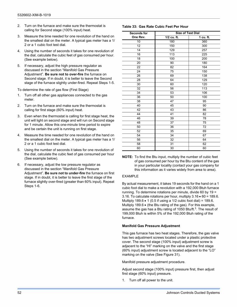
5326602-XIM-B-1019
52 Johnson Controls Ducted Systems
2. Turn on the furnace and make sure the thermostat is calling for Second stage (100% input) heat.
3. Measure the time needed for one revolution of the hand on the smallest dial on the meter. A typical gas meter has a 1/2 or a 1 cubic foot test dial.
4. Using the number of seconds it takes for one revolution of the dial, calculate the cubic feet of gas consumed per hour. (See example below).
5. If necessary, adjust the high pressure regulator as discussed in the section “Manifold Gas Pressure Adjustment”. Be sure not to over-fire the furnace on Second stage. If in doubt, it is better to leave the Second stage of the furnace slightly under-fired. Repeat Steps 1-5.
To determine the rate of gas flow (First Stage)
1. Turn off all other gas appliances connected to the gas meter.
2. Turn on the furnace and make sure the thermostat is calling for first stage (60% input) heat.
3. Even when the thermostat is calling for first stage heat, the unit will light on second stage and will run on Second stage for 1 minute. Allow this one-minute time period to expire and be certain the unit is running on first stage.
4. Measure the time needed for one revolution of the hand on the smallest dial on the meter. A typical gas meter has a 1/2 or a 1 cubic foot test dial.
5. Using the number of seconds it takes for one revolution of the dial, calculate the cubic feet of gas consumed per hour (See example below).
6. If necessary, adjust the low pressure regulator as discussed in the section “Manifold Gas Pressure Adjustment”. Be sure not to under-fire the furnace on first stage. If in doubt, it is better to leave the first stage of the furnace slightly over-fired (greater than 60% input). Repeat Steps 1-6.
NOTE: To find the Btu input, multiply the number of cubic feet of gas consumed per hour by the Btu content of the gas in your particular locality (contact your gas company for this information as it varies widely from area to area).
EXAMPLE
By actual measurement, it takes 19 seconds for the hand on a 1 cubic foot dial to make a revolution with a 192,000 Btuh furnace running. To determine rotations per minute, divide 60 by 19 = 3.16. To calculate rotations per hour, multiply 3.16 60 = 189.6. Multiply 189.6 1 (0.5 if using a 1/2 cubic foot dial) = 189.6. Multiply 189.6 (the Btu rating of the gas). For this example, assume the gas has a Btu rating of 1050 Btu/ft.3. The result of 199,000 Btuh is within 5% of the 192,000 Btuh rating of the furnace.
Manifold Gas Pressure Adjustment
This gas furnace has two heat stages. Therefore, the gas valve has two adjustment screws located under a plastic protective cover. The second stage (100% input) adjustment screw is adjacent to the “HI” marking on the valve and the first stage (60% input) adjustment screw is located adjacent to the “LO” marking on the valve (See Figure 31).
Manifold pressure adjustment procedure.
Adjust second stage (100% input) pressure first, then adjust first stage (60% input) pressure.
1. Turn off all power to the unit.
Table 33: Gas Rate Cubic Feet Per Hour
Seconds forOne Rev.
Size of Test Dial1/2 cu. ft. 1 cu. ft.
10 180 36012 150 30014 129 25716 113 22518 100 20020 90 18022 82 16424 75 15026 69 13828 64 12930 60 12032 56 11334 53 10636 50 10038 47 9540 45 9042 43 8644 41 8246 39 7848 37 7550 36 7252 35 6954 34 6756 32 6458 31 6260 30 60

5326602-XIM-B-1019
Johnson Controls Ducted Systems 53
2. Using the outlet pressure port on the gas valve, connect a manometer to monitor the manifold pressure.
3. Remove plastic cap covering HI and LO pressure adjustment screws.
4. Turn on power to the unit.
5. Set thermostat to call for second stage heat and start furnace.
6. If necessary, using a screwdriver, turn the second stage adjustment screw (adjacent to the “HI” marking on the valve) clockwise to increase manifold pressure or counterclockwise to decrease manifold pressure. Be sure not to over-fire the unit on second stage.
7. After the high manifold pressure has been checked, adjust the thermostat to call for first stage heat.
8. If necessary, using a screwdriver, turn the first stage adjustment screw (adjacent to the “LO” marking on the valve) clockwise to increase manifold pressure or counterclockwise to decrease manifold pressure. Be sure not to under-fire the unit on first stage.
9. Once pressure has been checked, replace the plastic cap covering the HI and LO pressure adjustment screws.
NOTE: When using natural gas, the manifold pressure for second stage (100% input) should be 3.5 IWG ± 0.3. The manifold pressure for first stage (60% input) when using natural gas should be 1.5 IWG ± 0.3.
Adjustment Of Temperature Rise
The temperature rise (the difference of temperature between the return air and the heated air from the furnace) must lie within the range shown on the CSA rating plate and the data in Table 14.
After the temperature rise has been determined, the CFM can be calculated as follows:
After about 20 minutes of operation, determine the furnace temperature rise. Take readings of both the return air and the heated air in the ducts (about 6 feet from the furnace) where they will not be affected by radiant heat. Increase the blower CFM to decrease the temperature rise; decrease the blower CFM to increase the rise (See SUPPLY AIR DRIVE ADJUSTMENT).
NOTE: Each gas heat exchanger size has a minimum allowable CFM. Below this CFM, the limit will open.
Burners/Orifices Inspection/Servicing
Before checking or changing burners, pilot or orifices, CLOSE MAIN MANUAL SHUT-OFF VALVE AND SHUT OFF ALL POWER TO THE UNIT.
1. Open the union fitting just upstream of the unit gas valve and downstream from the main manual shut-off valve in the gas supply line.
2. Remove the screws holding each end of the manifold to the manifold supports.
3. Disconnect wiring to the gas valves and spark igniter(s). Remove the manifold & gas valve assembly. Orifices can now be inspected and/or replaced.
To service burners, complete step 4.
4. Remove the heat shield on top of the manifold supports. Burners are now accessible for inspection and/or replacement.
NOTE: Reverse the above procedure to replace the assemblies.
Make sure that burners are level and seat at the rear of the gas orifice.
Figure 30: Typical Flame
Figure 31: Typical Gas Valve
Table 34: Gas Heat Stages
# of Burner Tubes2nd Stage
Input (100%Btuh)
1st StageInput (60%)
Btuh
6 175,000 105,000
8 240,000 144,000
HEAT EXCHANGER TUBE
BURNER FLAME(BLUE ONLY)
IGNITORBURNER BRACKET
BURNER
GASSUPPLY
PIPE
INLETPRESSURE
TAP
HIGH & LOW GAS ADJUSTMENT
OUTLETPRESSURE
TAP
HILO
ON
OFF
MATE-N-LOCKCONNECTORS
MV
C
HI
REGULATOR COVER SCREWS (REG. ADJ. BENEATH THESE SCREWS)
TERMINAL – HI (2ND STAGE)
ON/OFF SWITCH
C MP
OUTLET PRESSURE TAPINLET PRESSURE TAP
OR
TERMINAL – MP (1ST STAGE) TERMINAL – C (COMMON)

5326602-XIM-B-1019
54 Johnson Controls Ducted Systems
Charging The Unit
All ZF units use Thermal Expansion Devices. Charge the unit to nameplate charge or 10° subcooling.
Figure 32: Unit Control Board
Table 35: Ignition Control Flash Codes
Flashes Fault Conditions Check
STEADY ON Control Failure Control
HEARTBEAT Normal Operation
1 Not Applicable
2Pressure SwitchStuck Closed
Pressure Switch
3Pressure Switch FailedTo Close
Venter Pressure SwitchVent Blocked
4 Limit Switch OpenMain LimitAUX Limit
5
Flame Present With GasOff First Stage Gas ValveEnergized With W1 OffSecond Stage Gas ValveEnergized With First StageGas Valve Off
Gas Valve
6 Ignition Lockout
Gas FlowGas PressureGas ValveFlame Sensor
STEADY OFFNo Power Or Control Failure
24VAC or Control
W1W2Y1GY2
OCC
CSD-24
THERMOSTATWIRED HERE{ R
X

5326602-XIM-B-1019
Johnson Controls Ducted Systems 55
Table 36: Smart Equipment™ UCB Details
Description Function & Comments
Terminal Directional orientation: viewed with silkscreen labels upright
Limit, 24 VAC power and shutdown connections from unit wiring harness at left on upper edge of UCB
LIMIT Monitored 24 VAC input through heat section limit switch(es)
If voltage is absent, indicating the heat section is over-temperature, the UCB will bring on the indoor blower
C 24 VAC, 75 VA transformer Common referenced to cabinet ground
Connects through circuit traces to thermostat connection strip C and indoor blower VFD pin C
24V 24 VAC, 75 VA transformer hotPowers the UCB microprocessor, connects through circuit trace to the SD 24 terminal
SD 2424 VAC hot out for factory accessory smoke detector, condensate overflow and/or user shutdown relay switching in series
Connects through circuit trace to thermostat connection strip SD-24. A wiring harness jumper plug connecting SD 24 to SD R is in place if factory accessories for unit shutdown are not used - this jumper plug must be removed if the switching of field-added external accessories for unit shutdown are wired between thermostat connection strip SD-24 and R
SD R24 VAC hot return from factory accessory smoke detector, condensate overflow and user shutdown relay switching in series
Connects through circuit trace to the R terminal on the upper left of the board
R 24 VAC hot for switched inputs to the UCBConnects through circuit trace to the thermostat connection strip R terminal, right FAN OVR pin, right HPS1 pin, right HPS2 pin, lower DFS pin and lower APS pin
Terminal Thermostat connection strip on left edge of UCB
W1 1st stage heating request, 24 VAC input switched from R
Not effective for cooling-only units
W2 2nd stage heating request, 24 VAC input switched from R
Not effective for cooling-only units or units with single-stage heat sections
Y1 1st stage cooling request, 24 VAC input switched from R
Y2 2nd stage cooling request, 24 VAC input switched from R
Visible in the display menu when the #ClgStgs parameter is set for 2 or more, also effective for economizer free cooling supply air temperature reset when the #ClgStgs parameter is set for 1 or more
G Continuous indoor blower request, 24 VAC input switched from R
OCC Occupancy request, 24 VAC input switched from R
Must have the OccMode parameter set for External to be effective
X Hard lockout indicator, 24 volt output to a light thermostat LED
R 24 VAC hot for thermostat switching and powerIf field-added external accessories for unit shutdown are used, 24 VAC hot return from smoke detector, condensate overflow and/or user shutdown relay switching in series
SD-24
If field-added external accessories for unit shutdown are used, 24 VAC hot out for smoke detector, condensate over- flow and/or user shutdown relay switching in series
Unit wiring harness jumper plug for factory shutdown accessories must be removed if the switching of field-added external accessories for unit shutdown are wired between thermo- stat connection strip SD-24 and R
C 24 VAC common for thermostat power
LEDs on left edge of UCB
POWER Green UCB power indicator Lit indicates 24 VAC is present at C and 24V terminals

5326602-XIM-B-1019
56 Johnson Controls Ducted Systems
FAULT Red hard lockout, networking error and firmware error indicator
1/2 second on/off flashing indicates one or more alarm is currently active, 1/10th second on/off flashing indicates a networking error (polarity, addressing, etc.) or a firmware error (likely correctable with re-loading from USB flash drive)
SA BUS Green UCB SA bus communication transmission indicator
Lit/flickering indicates UCB SA bus communication is currently active, off indicates the UCB is awaiting SA bus communication
Terminal Space temperature sensor connections at center on upper edge of UCB
STSpace Temperature sensor input from 10KΩ @ 77°F, Type III negative temperature coefficient thermistor
Positive of VDC circuit (3.625 VDC reading to COM with open circuit), effective if “Thermo- stat-only Control” parameter is set OFF, space sensor override momentary shorts ST to COM to initiate/terminate temporary occupancy
COM Common for ST and SSO inputs Negative of VDC circuit for ST and SSO inputs
SSO Space Sensor Offset input from 0 to 20KΩ potentiometer
Positive of VDC circuit (3.625 VDC reading to COM with open circuit), 10KΩ/2.5 VDC is 0°F offset, 0Ω/0 VDC is maximum above offset and 20KΩ/3.4 VDC is maximum below offset from active space temperature setpoint
Pin Temperature sensor connections at right on upper edge of UCB
SAT+Supply Air Temperature sensor input from 10KΩ
@ 77°F, Type III negative temperature coefficient
thermistor
Input required for operation; 3.625 VDC reading SAT+ to SAT–
with open circuit. Used in heat/cool staging cutouts, free cooling operation, demand ventilation operation, comfort ventilation operation, economizer loading operation, VAV cooling operation, hydronic heat operation.
RAT+Return Air Temperature sensor input from 10KΩ @ 77°F, Type III negative temperature coefficient thermistor
Input required for operation; 3.625 VDC reading RAT+ to RAT–
with open circuit. Used in return air enthalpy calculation. Substitutes for space temperature if no other space temperature input is present.
OAT+Outside Air Temperature sensor input from 10KΩ @ 77°F, Type III negative temperature coefficient thermistor
Input required for operation but may be a communicated value;
3.625 VDC reading OAT+ to OAT– with open circuit. Used in
heat/cool cutouts, low ambient cooling determination, dry bulb free cooling changeover, outside air enthalpy calculation, economizer loading operation, heat pump demand defrost calculation.
CC1+#1 refrigerant circuit Condenser Coil temperature sensor input from 10KΩ @ 77°F, Type III negative
temperature coefficient thermistor
Input required for heat pump units, not required for A/C units;
3.625 VDC reading CC1+ to CC1– with open circuit. Used in
heat pump demand defrost calculation.
EC1+#1 refrigerant circuit Evaporator Coil temperature sensor input from 10KΩ @ 77°F, Type III negative
temperature coefficient thermistor
Input required for operation; 3.625 VDC reading EC1+ to EC1–
with open circuit. Used in suction line temperature safety.
CC2+#2 refrigerant circuit Condenser Coil temperature sensor input from 10KΩ @ 77°F, Type III negative
temperature coefficient thermistor
Input required for 2-compressor heat pump units, not required for 2-compressor A/C units, not active for 1-compressor units;
3.625 VDC reading CC2+ to CC2– with open circuit. Used in
heat pump demand defrost calculation.
EC2+#2 refrigerant circuit Evaporator Coil temperature sensor input from 10KΩ @ 77°F, Type III negative
temperature coefficient thermistor
Input required for operation of 2-compressor units, not active for
1-compressor units; 3.625 VDC reading EC2+ to EC2– with
open circuit. Used in suction line temperature safety.
Pinned connections on right edge of UCB
RAH+ Return Air Humidity input from 0-10 VDC @ 0-100% RH sensor
Input required for reheat units, optional in all other units, may be a communicated value. Used in return air enthalpy calculation, temperature/humidity setpoint reset, reheat operation.
DCT PRS+ Supply Duct Pressure input from 0-5 VDC @ 0-5” w.c. sensor
Input required for variable air volume units. Used in VAV indoor blower operation.
Table 36: Smart Equipment™ UCB Details (Continued)
Description Function & Comments

5326602-XIM-B-1019
Johnson Controls Ducted Systems 57
DFS (upper pin) 24 VAC hot return from Dirty Filter SwitchOptional input; switch closure for greater than 15 seconds during indoor blower operation initiates a notification alarm
DFS (lower pin) 24 VAC hot out for Dirty Filter Switch Connects through circuit trace to the R terminal
APS (upper pin) 24 VAC hot return from Air Proving Switch
When this optional input is enabled: the air proving switch must close within 30 secondsof initiation of indoor blower operation and not open for greater than 10 seconds during in- door blower operation to allow heat/cool operation and prevent an “APS open” alarm; the air proving switch must open within 30 seconds of termination of indoor blower operation to prevent an “APS stuck closed” notification alarm
APS (lower pin) 24 VAC hot out for Air Proving Switch Connects through circuit trace to the R terminal
C Common for the VFD output Negative of the VDC circuit for the VFD output
VFD 2-10 VDC (0-100%) output for the indoor blower Variable Frequency Drive
Output is active with indoor blower operation. For CV units: this output provides stepped IntelliSpeed control of the indoor blower VFD based on fan-only, cooling stage and heating stage outputs. For VAV units: this output provides control of the indoor blower VFD based on supply duct static pressure input and setpoint.
VFDFLT 24 VAC hot input from the normally open VFD alarm contact
The VFD alarm contact switches from R within the unit wiring harness. 24 VAC input results in unit shutdown and a “VFD fault” alarm
Terminal at lower right corner of UCB
24V FOR OUTPUTS 24 VAC hot for H1, H2, CN-FAN, AUX HGR, FAN C1 and C2 output relay contact switching
Output relay circuitry is isolated from other UCB components and the 24 VAC hot source may be from a second transformer in the unit
Pin Heat section connections at right on lower edge of UCB
H1 24 VAC hot output for heat section stage 1Not effective for cooling-only units. Output if demand is present and permissions allow one stage or two stages of heat section operation
H2 24 VAC hot output for heat section stage 2Not effective for cooling-only units or units with single-stage heat sections. Output if demand is present and permissions allow two stages of heat section operation
MV 24 VAC hot input confirming heat section operation
Sourced from gas valve in gas heat units or first stage heat contactor in electric heat units. Input within 5 minutes from initiation of H1 output initiates the “Heat On Fan Delay” timer, loss of input following the termination of H1 output initiates the “Heat On Fan Delay” timer, no input within 5 minutes from initiation of H1 output initiates an “Ignition Failure” alarm, input for longer than 5 minutes without H1 output initiates a “Gas Valve Mis-wire” alarm
Pin Cooling and fan output connections at right on lower edge of UCB
CN-FAN 24 VAC hot output for the condenser fan contactor coil
Output with either C1 or C2 output; interrupted during defrost cycle for heat pump units
AUX HGR 24 VAC hot output for hot gas reheat components Effective only for reheat units, output with reheat operation
FAN 24 VAC hot output for indoor blower contactor coil/indoor blower VFD enable relay coil
Output with heat/cool operation, G input or schedule demand
C1 24 VAC hot output for compressor 1If demand is present and permissions allow compressor 1 operation; output with compressor cooling, comfort ventilation cooling, reheat or heat pump heating demands
Table 36: Smart Equipment™ UCB Details (Continued)
Description Function & Comments

5326602-XIM-B-1019
58 Johnson Controls Ducted Systems
C2 24 VAC hot output for compressor 2
Not effective for one stage compressor UCBs. If demand is present and permissions allow compressor 2 operation; output with compressor cooling, comfort ventilation cooling or heat pump heating demands
Pin Refrigerant circuit safety switch and indoor blower overload connections at center on lower edge of UCB
HPS1(right pin)
24 VAC hot out for refrigerant circuit 1 High Pressure Switch
Connects through circuit trace to the R terminal
HPS1(left pin)
24 VAC hot return from refrigerant circuit 1 High Pressure Switch
Input is only considered if C1 output is needed; input must be present to allow C1 output. Three HPS1 trips in a two hour period cause a “High Pressure Switch 1 Lockout” and C1 output is then prevented until alarm reset. Connects through circuit trace to the right LPS1 pin.
LPS1(right pin)
24 VAC hot out for refrigerant circuit 1 Low Pressure Switch
Connects through circuit trace to the left HSP1 pin
LPS1(left pin)
24 VAC hot return from refrigerant circuit 1 Low Pressure Switch
Input is only considered after 30 seconds of C1 output; afterwards, input must be present to allow C1 output. Three LPS1 trips in a one hour period cause a “Low Pressure Switch 1 Lockout” and C1 output is then prevented until alarm reset.
HPS2(right pin)
24 VAC hot out for refrigerant circuit 2 High Pressure Switch
Not effective for one stage compressor UCBs. Connects through circuit trace to the R terminal
HPS2(left pin)
24 VAC hot return from refrigerant circuit 2 High Pressure Switch
Not effective for one stage compressor UCBs. Input is only considered if C2 output is needed; input must be present to allow C1 output. Three HPS2 trips in a two hour period cause a “High Pressure Switch 1 Lockout” and C2 output is then prevented until alarm reset. Connects through circuit trace to the right LPS2 pin.
LPS2(right pin)
24 VAC hot out for refrigerant circuit 2 Low Pressure Switch
Not effective for one stage compressor UCBs. Connects through circuit trace to the left HSP2 pin
LPS2(left pin)
24 VAC hot return from refrigerant circuit 2 Low Pressure Switch
Not effective for one stage compressor UCBs. Input is only considered after 30 seconds of C2 output; afterwards, input must be present to allow C2 output. Three LPS2 trips in a one hour period cause a “Low Pressure Switch 2 Lockout” and C2 output is then prevented until alarm reset.
FAN OVR(right pin)
24 VAC hot out for indoor blower FAN Overload relay contact/motor protector switch
Connects through circuit trace to the R terminal
FAN OVR(left pin)
24 VAC hot return from indoor blower FAN Overload relay contact/motor protector switch
Input is only considered if FAN output is needed; input must be present to allow FAN output and unit operation. One FAN OVR trip lasting longer than 5 minutes or three FAN OVR trips in a two hour period cause a “Fan Overload Lockout” and unit operation is then prevented until alarm reset.
Terminal SA BUS connections on at left on lower edge and center of UCB
PWR Power for SA (“Sensor-Actuator”) BUS devices
Also incorporated in the J8 6-pin phone jack connector at the left-center of the board. Positive of the 15 VDC (reading to C) circuit for powering an optional netstat and/or Multi Touch gateway
C Common for SA BUS power and communication circuits
Also incorporated in the J8 6-pin phone jack connector at the left-center of the board. Negative of the SA BUS circuits
– Communication for SA BUS devices
Also incorporated in the J8 6-pin phone jack connector at the left-center of the board. Positive of the VDC (typically, a fluctuating 1.5 to 3.5 volts reading to C; at least 0.25 volts lower than +) SA BUS communication circuit to optional economizer board, 4-stage board, fault detection & diagnostics board, netstat and/or Multi Touch gateway
Table 36: Smart Equipment™ UCB Details (Continued)
Description Function & Comments

5326602-XIM-B-1019
Johnson Controls Ducted Systems 59
+ Communication for SA BUS devices
Also incorporated in the J8 6-pin phone jack connector at the left-center of the board. Positive of the VDC (typically, a fluctuating 1.5 to 3.5 volts reading to C; at least 0.25 volts
higher than –) SA BUS communication circuit to optional
economizer board, 4-stage board, fault detection & diagnostics board, netstat and/or Multi Touch gateway
J8 6-pin phone jack connectorIncorporates the SA BUS terminals for convenience/alternate connection of SA BUS devices, primarily used for temporary service connection of the Multi Touch gateway
Item Integrated user interface at lower left corner of UCB
Display On-board, 2-line x 8-character back-lit displayOn-board display, buttons and joystick allow access to UCB, economizer, 4-stage and FDD board parameters
ENTER Button for display menu acknowledgment and navigation
CANCEL Button for display menu navigation and zeroing of active compressor ASCD timer
JOY 4-way Joystick for display menu navigation
Item USB connector at right of UCB
J10 Type A female Universal Serial Bus connectorUsed for backup, restoration, & copying of board parameters as well as board software updating through a flash drive
J15 Factory wired SA Bus connector
Optional communication sub-board at center of UCB
Terminal FC BUS connections on left edge of the communication board
FC+ FC (“Field Connected”) BUS BACnet MSTP communication
Positive of the VDC (typically, a fluctuating 1.5 to 3.5 volts
reading to COM; at least 0.25 volts higher than –) FC bus
BACnet MSTP communication circuit
FC– FC (“Field Connected”) BUS BACnet MSTP communication
Positive of the VDC (typically, a fluctuating 1.5 to 3.5 volts reading to COM; at least 0.25 volts lower than +) FC bus BACnet MSTP communication circuit
COM Common for the FC (“Field Connected”) BUS BACnet MSTP communication circuit
Negative of the VDC FC bus BACnet MSTP communication circuit
SHLD Shield for the FC (“Field Connected”) BUS BACnet MSTP communication circuit
Earth ground reference of the cable to prevent interference on the FC bus BACnet MSTP communication circuit
Item Selector in red housing at left on top edge of the communication board
EOLswitch
End Of Line selector switch for the FC BUS BACnet MSTP communication circuit
ON selected only for the UCB that is the terminus of the FC bus BACnet MSTP communication cable to prevent signal “bounce-back”
LEDs on the communication board
EOL Green End Of Line indicator Lit indicates the EOL switch is selected ON
FC BUS Green FC bus communication transmission indicator
Lit/flickering indicates outgoing UCB FC bus communication is currently active, off indicates the UCB is awaiting incoming FC bus communication
ISO PWR Green communication board Isolated Power indicator
Lit indicates the UCB is supplying power to the communication sub-board
Table 36: Smart Equipment™ UCB Details (Continued)
Description Function & Comments

5326602-XIM-B-1019
60 Johnson Controls Ducted Systems
Start-Up Sheet

5326602-XIM-B-1019
Johnson Controls Ducted Systems 61

5326602-XIM-B-1019
62 Johnson Controls Ducted Systems

5326602-XIM-B-1019
Johnson Controls Ducted Systems 63

5326602-XIM-B-1019
64 Johnson Controls Ducted Systems
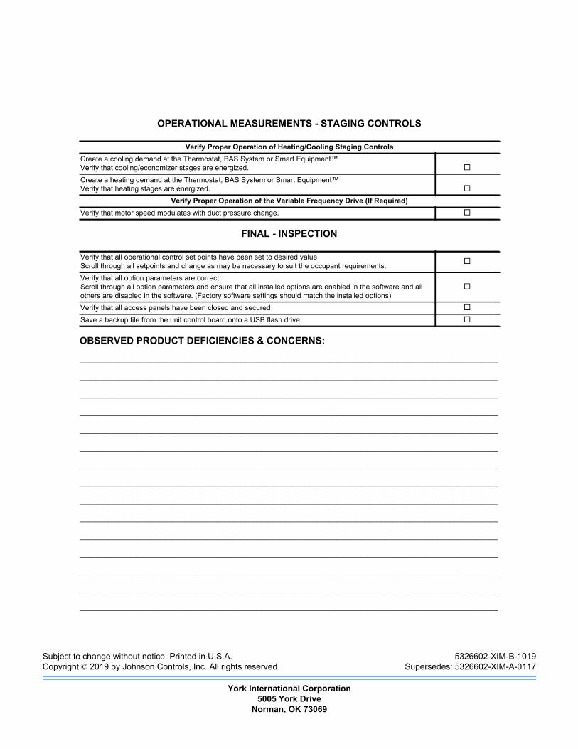
Subject to change without notice. Printed in U.S.A. 5326602-XIM-B-1019Copyright © 2019 by Johnson Controls, Inc. All rights reserved. Supersedes: 5326602-XIM-A-0117
York International Corporation5005 York Drive
Norman, OK 73069