Embed Size (px)
Citation preview

ED 124 384
TITLE
INSTITUTIONSPONS AGENCY
PUB DAV',NOTE
so'
DOCUMENT RESUME4
88 .
.4>
SE 019 607
0Let There Be Light " Minicourse, Career OrientedPre - Technical physieV74Dallas Independent School District, Tex,Bureau a Elemen'tary and Secondary Education'(DHEW/OE),' Washington, D.C.74134p.; Photographs and shaded drawings may notreproduce well; Vox related documents, see SE 018'322-333 and SE, 019 605-616
4
EDRS PRICE MF-$0.83 HC-$7.05 Plus Postage.DESCRIPTORS Instructional Materials; Light; *optibs; Physics;
*Program Guides; *Science Activities; ScienceCareers; Science Education; *Science Materials;Secondary Eddcation; *Secondary School Science;Technical Education
IDENTIFIERS AX Secondary Education Act'Title III; ESEATitle III
ABSTRACTThis instructional guide, intended for student use,
develops the concept of light through a series of,sequential.activities. A technical development of the subject is pursued withexamples stressing practical aspects of the concepts. In-cluded in theminicourse are: (1) the rationale, (2)-terminal behavioralobjectives, (3) enabling behavioral objectives, -(4) activities, (5)
resource packages, and (6) evaluation materials. Along with adefinition of light, the concepts of reflection and refraction andsuch topic as fiber light and the photoelectric effect are.developed. his unit is one of "twelve intended for use in the second .
year of a tw year vocationally oriented physics program. (CP)
o
**************A********************************************************Documents acquired by ERIC include many informal-unpublished
* materials. not available from other sources. ERIC makes every effort ** to obtain the best copy available. Nevertheless,, items of marginal *
* reproducibility are often encountered, and this affects the quality *
* of the microfiche and hardcopy reproductions ERIC makes. available *
* Via the ERIC Document Reproduction Service (EMS). EDRS is not .*
* restionsible for the quality of'the original document. Reproductions *supplied by EDFS are t)6 best that can be made/from the original.
**************************************************************Ic******
CAREER ORIENTED PRE-TECHNICAL PHYSICS
'Let There Be Light"
Minicourse
ESEA Title III Project
1974
le
dabs
inde
penc
ian-
tci
stac
t
US
DE
PA
RT
ME
NT
OF
HE
ALT
HE
DU
CA
TIO
N &
WE
LFA
RE
NA
TIO
NA
L IN
ST
ITU
TE
OF
EC
IIIC
T IO
N
"-B
EE
N R
EP
W:
X4.
-'-44
Rf C
E .E
L cR
C *
tPE
G.',R
.-7,
A. Z
Afr
aN
h:;
. E 1
CR
NC
NS
L'a
N:-
.TE
CE
EP
RE
-E
....1
c;c
a. P
14E
r_f.e
1
0
0
- B
OA
RD
OF
ED
UC
AT
ION
.E
uger
ib S
. Sm
ith. J
r,P
resi
dent
Bill
C. H
unte
r. V
ice-
Pre
side
nt
Em
met
t J. C
onra
d, M
.D'L
awre
nce
Her
kim
er
Jam
es J
enni
ngs
Kat
hlyn
Gill
iam
Nan
cy J
udy.
'S
arah
Has
kins
Rob
ert M
edra
no
a
'A
DM
INIS
TR
IE O
FF
ICE
RS
Nol
an E
tes
Gen
eral
Sup
erin
tend
ent
,H. S
. Grif
finD
eput
y Su
peri
nten
dent
-R
oger
s L.
Bar
ton
Ass
ocia
te S
uper
inte
nden
tD
evel
opm
ent
Fra
nces
Alle
nH
. D. P
ears
onA
ssis
tant
Sup
erin
tend
ent
Ass
ista
nt e
uper
inte
nden
tA
dapt
ive
Edu
catio
nB
usin
ess
Larr
y A
scou
ghA
ssis
tant
Cup
dent
Com
mun
icat
ions
Otto
M. F
ridia
, Jr.
Ass
ista
nt S
uper
inte
nden
tG
eorg
e R
eid
-E
lem
enta
ry O
pera
tions
Ass
ista
nt S
uper
inte
nden
tSe
cond
ary
Ope
ratio
nsR
uben
. Gal
lego
sA
ssis
taiu
Supe
rint
ende
ntPr
ogra
m D
evel
opm
ent
Car
lton
C. M
offe
ttA
ssis
tant
to th
e G
ener
al S
uper
inte
nden
t
-1B
en N
iede
cken
Atto
rney
c
"i Jo
e M
. Pitt
sA
ssis
tant
Sup
erin
tend
ent
Pers
onne
l Dev
elop
men
t
John
J. S
antil
loA
ssis
tant
Sup
erin
tend
ent
Pers
onne
l
11 J
. Sta
mps
Ass
ista
nt S
uper
inte
nden
tse
- Inst
ruct
iona
l Ser
vice
s
Wel
don
Wel
lsA
ssis
tant
Sup
erin
tend
ent
Supp
ort S
ervi
ces

detli
as. i
ndep
ende
nt s
choo
l dis
tric
t
October 8,,1974
Nol
an E
stes
Gen
eral
This Minicourse, is a result of hard work, dedication, and a com-
prehensive program of testing And improvement by members of the
staff, college professors, teachers, and others.
The Minicourse contains clasgroomatti*ties designed for use in
the cegulgr teaching program in the Dallas indepeildent School
District.
Through minicourseiactivities, students work indepen-
dently with close teacher supervision and aid.
This work is a.
fine example of the excellent efforts for which the Dallas
Independent School District is known.
May I commend all'of those.
who had a part in designing, testing, and improving this Minicourse.
I commend it to your use.
NE:mag
Sincerely yours,
C1/1/1/4.0
1441-)'
Genera
Superintendent
'
C)1
CAREER ORIENTED PRE - TECHNICAL PHYSICS
'"LET THERE BE LIGHT"
MINICOURSE
RATIONALE (What this
minicourse is about)
This minicouyse will, introduce you to some
of the techhicai aspects of light.
Light is so much a part
of our environment that many people neverconsciously try to Understand its nature,nordo they learn
to appreciate the vital
roles'it plays.
Two vital rele's'which light plays
in our lives are concerned
with vision and with photosynthesis (the process
whereby green plants use light energy tomanufaoture
plaht products).
However, language pays tribute to
light--we say, "We're in the dark, when wedon't know something; and
we use, the expression,
"throwing some light on the subject,"
when we have overcome a problem.
When,
things are not going well, we say we are
in a "dark" mood.
We also speak of "black" magic
(evil), or
a "br ght day" (when things are going
well); and who has not heard about
(or viewed) the "soap opera"
called The Guiding Tight?
Keep a folder or notebook containing a neat
account of your investigations,
obserirations, and other
written work required/Jot this
minicourse; this account will be used as one
basis for evaluation of
your work,
a
In addition to the Rationale; this minicourse contains the
folloWing
4
1)
TERMERAL. BEHAVIORAL OBJECTIVES (Specific things you are exptcte
learn from he minicourse)
2)
ENABLING BEHAVIORAL OBJECTIVES (Learning "steps" whichWilVenable you to eventually
each
the to m nal behavioral objectives)
3)
ACTIVITIES- (Specific things to do to help you learn)
4)
RESOURdE FACkAGES (Instructions for carrying out the learning Activities, such as procedures,'
references, laboratory materials, etc.
5)
EVALUATION (Tests to help you learn and to determine whether or not yousatisfactorily reach
the terminal behavioral objectives):
.a) Self-test(s) with answers,to help you learn more.
b) Final test, to help measure your overall achievement.
CZ
TERMINAL BEHAVIORAL OBJECTIVES:
When you have completed this minicourse, you will demonstrate anUnderstanding of some o
the basic tech-
nical ideas of light by being able to:
.
1)
trace man's attempts to determine the
Propertie 'and speed of light and to write a simple
description of light.
2)
explain, in terms of a simple model, the release of photoelectrons from
light-sensitive metal
surfaces and to discuss some of the general behavior of photoelectrons.
show familiarity with the laws of reflection of light by a plane mirror
and_the,images formed
by a plane mirror and to construct ray diagrams for the formation of
simple images-in a plane
mirror.
c**
-2-

4)
show familiarity with the properties of light, striking a curved mirror and the images formed
by the curved mirror, to construct ray diagrams for the formation of simple images by a
curved mirror, and to use mirror formulas for` determining the location and,size of images.
5) -show familiarity with the basic concepts of 'the refraCtion of light and to utilize and apply
the laws of refraction to simple cases.
6)
solve simple prbblems in photometry.
7)
identify some optical principles used in fiber optics.
8)
describe a simple model of polarized light and list some technical applications of such light.
9)
describe a simple model of the phenomena of interference and diffraction of light.
ENABLING BEHAVIORAL OBJECTIVE #1:
Roughly describe attempts to
determine the properties and
speed of light, and write an
acceptable description of
light.
ENABLING BEHAVIORAL OBJECTIVE, #2:
Understand the laws of reflec-
,
tion,pf light by'a plane mirror,
understand the images formed by
a plane mirror, and construct
ray diagrams for the formation
of images on a plane mirror.
ACTIVITY 1-1
Read and complete Resource Packages
1-1, 1-2, and 1-3.
ACTIVITY 2-1
Read and complete Resource Packages.
2-1.1 dirobugh 2-1.7.
.
RESOURCE PACKAGE 1-1
"What Is Light?"
RESOURCE PACKAGE 17-.2
"Speed of. Light"
RESOURCE PACKAGE 1-3
"Description of Light"
RESOURCE PACKAGE 2 -1.1.
"Reflection I"
RESOURCE PACKAGE 21.2
"Reflection" II"
RESOURCE PACKAGE 2-,1.3
"Reflection III"

ENABLING BEHAVIORAL OBJECTIVE #2:
(For a statement of this objec-
ve, please see page
3 of this
mlnico
JO
ENABLING BEHAVIORAL OBJECTIVE #3:
Describe the general properties
- of light striking a curved mir-
ror; describe and illustrate
the
images formed by a curved mirror;
use'che mirror formula to
deter-
mine the site-and location of
images.
N
ACTIVITY 2-2
Complete Resource Package 2-2.1
and check your answers using
.
Resource Package 2-2.2.
ACTIVITY 3 -1
Read and complete Resource Packages
3-1.1 through 3-1.6.
al>
-.4-
'"I
RESOURCE PACKAGE 2-1.4
"Reflection IV"
RESOURC)
PACKAGE 2-1.5
"Mirror, Mirror on the
Wall"
RESOURCE PACKAGE 2-1.6
"Image,,problem"
RESOURCE PACKAGE
"Some Applications"
RESOURCE PACKAGE 2-2.1
"Reflection Exercise"
-lam
=CKAGE 2-2.2
"Answers"
RESOURCE PACKAGE 3-1.2
"Curved Mirror Investi-
gation"
RESOURCE PACKAGE 3-1.2
"Curved Mirrors"
RESOURCE PACKAGE 3-1.3
"Ray Construction"

A
,ENABLING BEHAVIORAL
(For a statement
tive, please see
minicourse.)
OBJECTIVE #3:
of this objec-
page 4 of this
ENABLING BEHAVIORAL OBJECTIVE #4:
Describe a simple mddel for
/'
the refraction of light; explain
and apply-the laws of refrac-
tion.
ACTIVITY 3-2
'Complete Resource Package
-2.1
and check youi answers using
Resource Package 3-2.2.
ACTIVITY 4-1
Read and complete Resource Packages
4-1.1 through 4-1.4.
-5:
A
4
RESOURCE PACKAGE 3-1.4
"CustoMer Satisfaction"
4
RESOURCE PACKAGE 3-1.5
"Curved Mirror Usage"
RESOURCE PACKAW 3 -1.6
"The Old Light-Bulb-In-
The-mpty-Socket Trick!.
RESOURCE PACKAGE 3-2.1
"Curved Mirror Exercise"
RESOURCE PACKAGE 3-2.2
"Answers to Exercise"
RESOURCE PACKAGE 4-1.1
"Refraction I"
RESOURCE PACKAGE 4-1.2,,
"Refraction II"
RESOURCE PACKAGE 4-1.3
"Index of Refraction"
RESOURCE PACKAGE 4-1.4
"Atmospheric Refraction"
1

\
ENABLING BEHAVIORAL OBJECTIVE #5:
Develop fundamental skillsre-
lated to solvinglr
iob/ems in
photometry.
ENABLING BEHAVIORAL OBJECTIVE #6:
Identify some optical princi-
ples used in fiber optics.
ENABLING BEHAVIORAL OBJECTIVE #7:
Identify some principles and
j.technical applications of
polarized light.
ENABLING_ BEHAi.TIORAL OBJECTIVE #8:
Describe a simple model for the
phenomena o
interference and
diffraction of light.
"-
,ACITTVITY5-1
Read and complete Resource Package
5-1.1 Ana 5-1.2.
ACTIVITY 6-1
,Read and complete Resource Packages
6.1.1 and 6-1;2.
ACTIVITY 7-1
Read and complete Resource Packages%
-
ACTIVITY 8-1
Read and complete Itesource Packages
8-1.1 and 8-1.2.
ACTIVITY 8-2
:Complete Resource Package 9/2.1
and check
ur answerb using
Resource Pac
ge 9-2.2.
-6-
1:7"--7777.414.
RESOURCE 'PACKAGE 5-1.1
"Illumination"
RESOURCE PACKAGE 5-1.2
-"Photometry"'
RESOURCE PACKAGE 6-1.1
"Refx-active-Fibers"
I
RESOURCE_ PACKAGE 6-1.2
;Tiber Light"
RESOURCE PACKAGE 7-1.1'
"Polarized Light I"
RESOURCE PACKAGE 7-1.2
"Polayd.zed Light II"
RESOURCE PACKAGE a-la
"Interference"
PSOURCE PACKAGE 8-1.2
"Diffraction"
4RESOURCE PACKAGE 8-2.1
"Self-test"
.st
A.
fi
ENABLING BEHAVIORAL OBJECTIVE #8:
'
(For a statement of this objec-
tive, please see page 6 of this
minicourse.),
ENABLING BEHAVIORAL OBJECTIVE #9:
Study the felease of photo-
electrons from light-sensitive
metal surfaces.
_
TERMINAL, EVALUATION
ACTIVITY 9-1
4
and complete Resource Package
'
9-1.1.
ACTIVITY 10 -1
When you feel ready, ask your
instructor for the Final Eval-
uation:
(Good luck!)
RESOURCE_ PACKAGE 8,2.2
"Self-test
wers"
RESOURCE PACKAGE 9-1.1
"Photoelectric Effect"
RESOURCE PAC
10-1.1
"Final
Eitluation"
!...1
t
RESOURCE PACKAGE 1-1
WHAT IS LIGHT?
gh
Historical records tell us thar...-people have long tried to
determine the
properties/Of light.
For some,
"Let there be light, and there was-light," provided a s4iffitient explanation
of light's origincefor
others, this
this explanation was insufficient to satisfy their curiosity
because it did not tell anything'
about light itself.
I
Listed below are a group of men who lived sometime. during the period,,fifth
century B. C. to modern
times, who played important roles in discovering properties
of light.
Write a brief description of each
7A.
,
man's idea(s)regarding the propertied of light and,
whtre appropriate, tell how these properties re--
a
lated to the development of later ideas.
Ask your instructor for suitable references should you not
be
asure where to find
igis,limormation.
1.
Empedocles -(Greek ,philosopher) -
2.
Aristotle (Greek philosopher) -
cr
3.
Rene/Descarte (French mathematician)
4. -Alhazen (Arabian physicist) -
. Francisco Maria
Giimaldi (Italian
;1"--****"
6.
Robert Hooke (Engiish physicist) -
7.
Christian Huygens
°N-
'
1/4$
priest) -
(Dutch physicia0
v.or
*.
1
e
Isaac Newton (English physicist). -.
.Thomas Young (English physicist) -
10:
James Clark Maxwell:(English physicist)
11.
Augustin FresnelFrench physicist)
12.
Max Plank (German physicist) -
13.
Altiert Einstein (German physicist) -
-19-
Ne,
1

st
RESOURCE PACKAGE 1-2
THE SPEED OF.LIGHT
In endeavors to determine the properties
of light, its,speed has been of utmost importance.
A widely
.
`,
.held current belief is that the speed of light in free space
(a vacuum) is the highest possible speed
.
attainable in the universe.
Because this speed (denoted by the symbol, c) is one
of the mpst important
physical constants, its precise determination is an important-achievement,of experimental science.
OListed below are a group of men who contributed to the
determination of the:spged of.light.
Write a
short description of the
process each man used in his
investigation and draw a rough (but neat) sketch
.of the situation or apparatus used.
Your instructor can give you appropriate references..
kplb.
1.
Galileo Galilei -
2.
Olaus Roemer -
3.
.M. LFizeau -
4.
Leon Foucault
5.
Albert Michelson -'
4
Also, search literature for the latest value of the speed of light in free space; in m/sec and in
mi/sec.
Inter these values and their source in your notebook.
RESOURCE PACKAGE 1 -3
DESCRIPTION OF LIGHT
iilow that you have read about
these scienti ts' search for a meaningful'explanationof light and about
A
their efforts to determine the speed cf light,
write your own description of light in your
notebook.
Ask your instructor to check your descriptibn.
*I&
11.
-13-
a

RESOURCE PACKAGE 2-1.1
REFLECTION I
You will need the following:
plane mirror
4
woodet block
wooden drawing board
drawing compass
protractor
-ruler
rubber-bands
Arrange the app'aratus as shown in Fig. 1.
Dfaw a line along the center of your paper and
label it with an "X"-Jat each end.
Fasten your
s mirror to the block of wood and place the mir-
ror on the paper so that the reflecting surface
is aligned with the "X". line (see Fig. 1).
11.
ig.
ANGLES OF INCIDENCE AND REFLECTION
SOL
Place a pin about 5 centimeters in front of the mirror and label this point, "P" (see Fig. 2 on next
page).
Lay a ruler on the paper so that it is to the right'of the pit and in front of the mirror.
-Look
along the edge of the ruler at the image of the-pin in the mirror (see Fig. 1, above).
When the edge of
the ruler is directly in line with the image of the pin, draw a line along the ruler edge (line A,
Fig. 2).
Use the same procedure to locate
.e image on the let side of the pin (line.B, Fig. 2).
A
-15-

r
X
Mirror surface line
,
LOCATING THE IMAGE POINT (I)
Fig. 2
Remove-the mirror and pin.
Draw a line through "P" perpendicular to
dicular a short distance beyond the mirror surface line ("X"
4on the leftland right side of "P" until they intbrsect (behind the
label the-line on the right "IA" and
on the left, "IB:"
Your raving
.0
the "X"
this perpen-
Now ex
dhe lines yoU have drawn
Label this point, "I";
d look like Fig. 2.
I
Now, construct a perpendicularIline, "CD," at the
point where line, "IA" intersects the "X" line (see
Fig. 3 on next page).
. Label this point of intersection
DAOwa,liqe betweenients,"P" and "C."
416
*- -16-
"C."
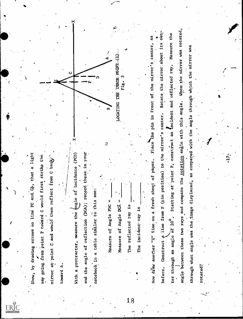
Show, by draWing arrows On
line PC and,C4, that a light
ray going from point P
tocerd C would first Strike the
mirror. at. point C and would then reflect from C bagisr.
toward A.
---, -
With a protractor, measure the
ngle of incidence (PCD)
and the angle of reflection (DCA); record these in your
notebook in a table similar to this one:
Measure of Angle PDC =
Measure of Angle DCA =
The reflected ray is
,1
00
The incident' ray is
-
Now draw another "X" line on a fresh sheet of phper.
Place the pin in front of. the mirror's center, as
-
LOCATING THE TENGEj102.MT__W_______
Fig. 3
t
before.
Construct
line from P (pin position) to the mirror's center.
Rotate the mirror about its cen:
ter through an angle of 20o
Starting at-point P, construct anIncident.andreflected
ray.
Measure the
-.
angle between these two rays and compare the rotation angle with
this angle.
When -,the mirror was rotated,
through what angle was the.lmage displaced, as compared
with the angle through which the mirror was
rotated?
-17:
Is

r
RESOVRCE PACKAGE 2-1.2
REFLECTION?
.Sit in'front of a mirror and attempt to draw the
diagrp.m.below, looking only at the reflection of
the
liagram
(see Figures 1 and 2).
Write in your
notebook a brief explanation of why this drawing is
a difficult task.
DRAWING1ROMA REFLECTION
Fig.
1,
-19-
DIAGRAM
Fig. 2.

1 1
t5D
co
RESOURCE PACKAGE 2-1.3
REFLECTIO
You have seen that light strik*
a plane mirrc1r surfaCe is reflected
(sometimes cal
a Law of Reflection); i.e., the
angle of incidence
(r), or i = r., Now, let's investigate how this law can be
applied to
by a plane mirror.
INVESTIGATINO'TBE LOCATION OF A PLANE MIRROR IMAGE
You will need:
according to a law of reflection,
(i) equals,the angle of reflection
the location of the image produced
same equipment listed in Resource Package
2-1.1 (see'page 15)
Draw the "X" line across a large sheet of paper.
Place-the-mirror on the line as was done in
Resource Package 2-1.1.
Draw an arrow on the
paper about 6 to 7 cm in front of
the mirror.
Make'the arrow about 2 cm longm and slanted so_,
that-the head of-the arrow is closer to the
ror.
Stick a pin Vertically_into --the head of the
arrow and sight along,the
ruler's edge toward the
head of the arrow's image (see Fig, 1).',
L-21-
Fig. 1
LOCATING THE
IMAGE
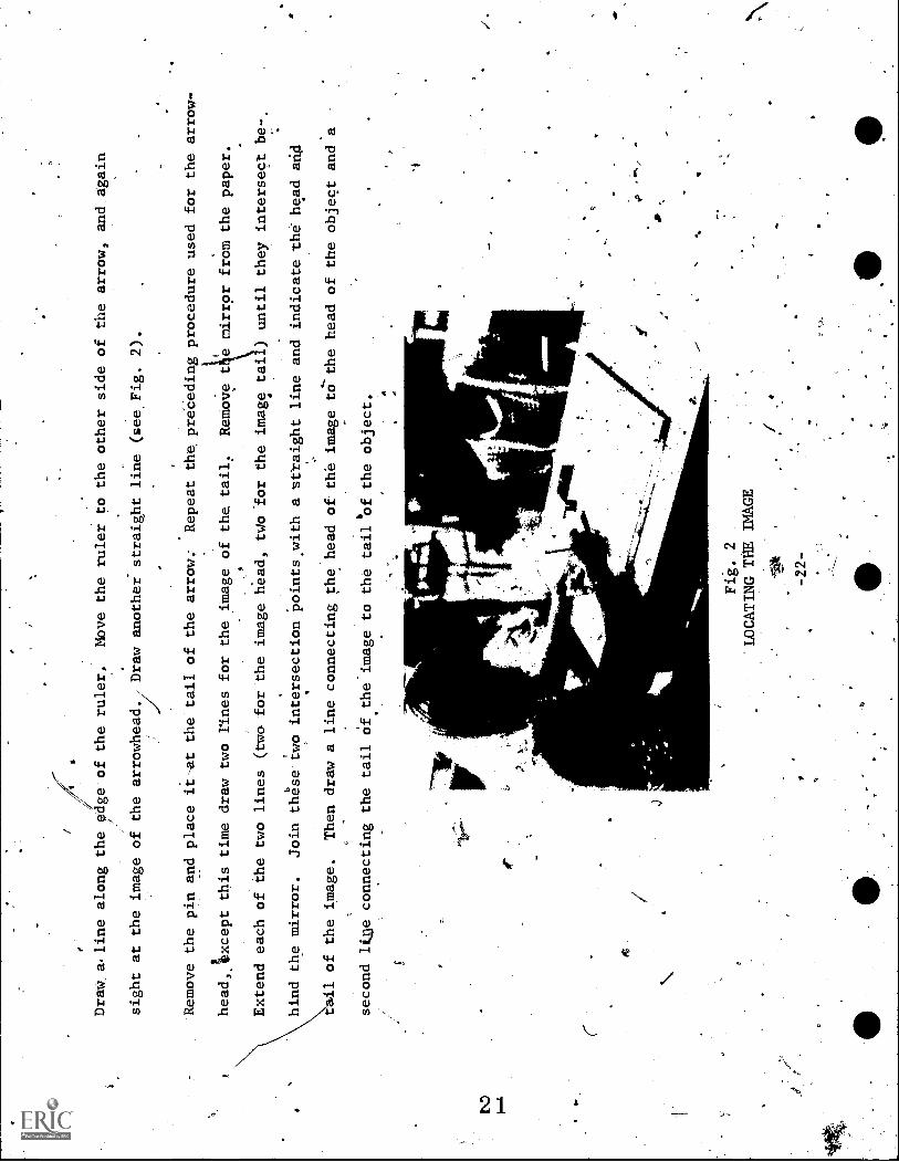
Draw a.line along the edge of the ruler.
Move the ruler to the other side of the arrow, and again
sight at the image of the arrowhead.
Draw another straight line (see, Fig. 2).
Remove the pin and place it-at the tail of the arrow:
Repeat the preCeding procedure used for the arrow-
head,Axcept this time draw two lines for the image of the
tail:
Remove t e mirror from the paper.
\\\\.a.
..
Extend each of the two lines (two for the image head, tWo 'for the
image tai ) until they intersect be-
hind
tt
points
hind the mirror.
Join these
wo intersection
with a straight line and indicate the head mid
.
t it of the image.
Then draw a line connecting the head of the image to` the head of the object and a
4second l &e connecting the tail of the image to the tail of the object.
Fig. 2
LOCATING THE IMAGE
-*t1
-22-
*
4,*
4
9
Dist
e of head of object tb mirror
Distance o
ead of image to mirror
bject to mirror
Distance of tail of
Distance of tail of image to mirror
Length of object =
Lengt
of` image
=
=cur,
cm
CM
CM
cm
Write down a comparison of the siz
of the ima
and of the Obje&t..
Describe the location of-the image.
Record the comparative distance from the,mirrdr to the image and the object.
Describe the type of image
, [NO
(real or virtual; inverted or erect; straight or perverted ).
tO
,se
0
THOUGHT QUESTION
If you stand 10 meters from a mirror,, how far 'are you from your image?.. If you walk toward a mirror at
the rate of 3 meters/sec, how fast do you approach your image?
-23-
,4
Jo/
a
.RESOURCE PACKAGE 2-114
REFLECTION IV
A
Light appears to travel in a straight line.
then, we can 'consider that lig t'travels in
0
For example, we can't see around corners.
For our-purposes,
a straight line, bending only if it travels from one
medium
to another (such as frqm air to water; from glass to plastic; etc.) or when it passes
the sharp edge of
an obstacle.
Later, you will 'Study the bending of light by a medium (refraction) and the
bending of
light, by an obstacle (diffraction).
.Let's conside
medium?"
Well,
the question, "What happe's when light traveling throdgh a-first mediuth strikes a
second
oral things can happen:
1.
some light may be reflected;
2.
some light mnybe,refracted;
3.
some light maY be absorbed;
4. 4:slue light may be transmitted.
0
0
If it-were, not for the reflective properties of objects, oureyei would be of little use, because most
.40
objects we/see are visible because of reflected light.
Just by looking around right now,,you can see
how much vision depends upon light reflection; i.e., eve
ou can see is because of reflected
light except for luminous objects (luminous means light roducing, such as the sun, a:Candle, etc.).
r-
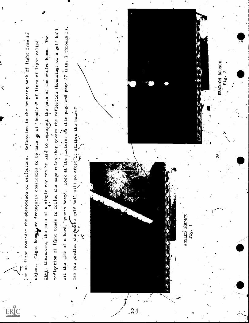
Let us first Consider the Phenomenon of reflection.
Reflection is the bouncing back of light from an
object. :Light bealle re frequently considered to be made
u Ap of "bundles" of lines of light called
rays; therefore, the path of a single ray can be used to sep.ree5t the path of the entire beam.
1 e
is
e
reflIction of light tends to follow the same rulesthatgovern the reflection (bouncing) of a golf ball
off the side of a hard, spooth board.
Look.at the pictu;'es ah this page and page 27 (Fig. 1 through 3).
Can you predict whe 4-*
t e golf ball will go after'it strikes- the board?
.:11s
otsa
. das
el.e
e.OOOOOO
POOOM011611.1011.0.V.I. OOOOO
1,1111110.
%%%%%
tfos.,mat;WPOOlge
.0#111,
71"
anar
%%
%
41.
11
A
ANGLED BOUNCE
Fig. 1
II"
4 ""
4,
%c;
ofg
%to. I
%"Ise Coe le
%%%%% 74.411.02.4i4Zessta,aa.. teas.
st
-26-
HEAD-ON BOUNCE
Fig. 2
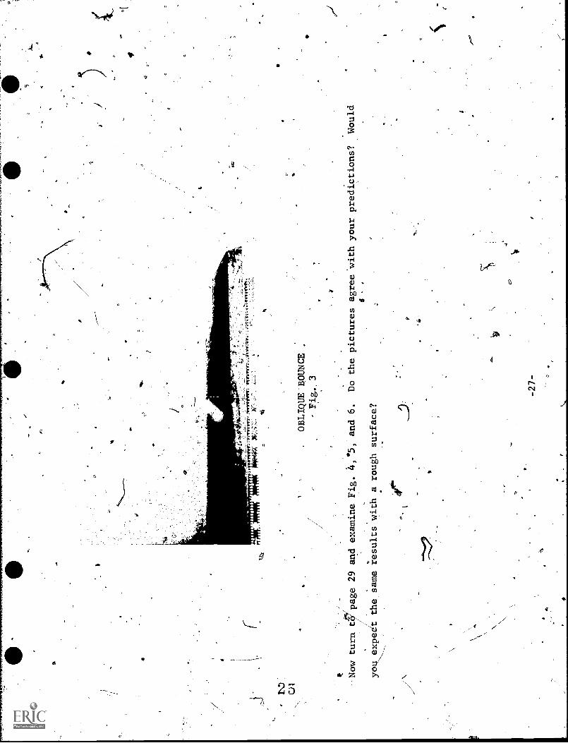
.OBLIQUE 'BOUNCE
- Fig,. 3
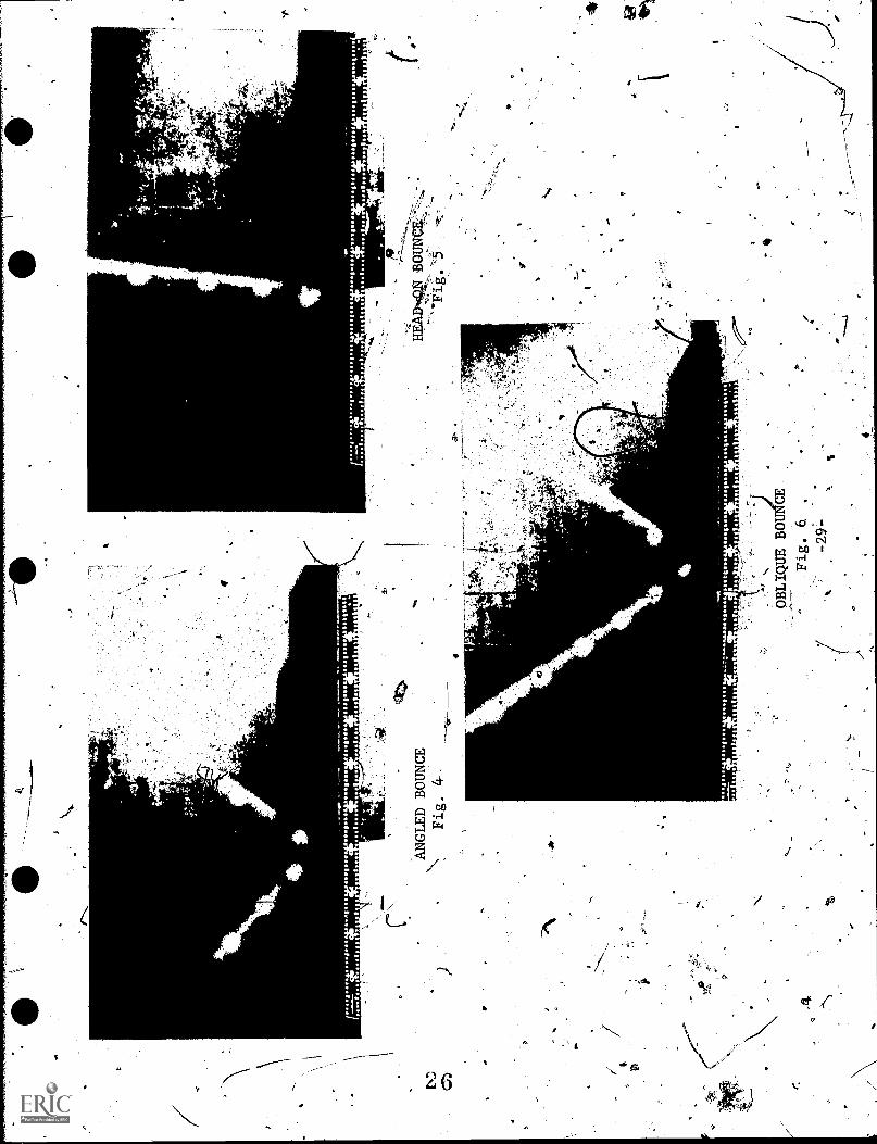
Now turn t
page 29 and examine Fig. 4,.5, and 6.
Do the pictures agree with your predictions?
Would
4.
yob expet the same results with a rough surface?
-27-
4
at
400,0..
0100.1.141,11:004,112.
01061.1
1.1,111101 a ***
* . **
r...SOO
Of
r
II
1
al,
o
010.00tir$0(a60
00.040
41 gto 9,140
111011
Olga
13
11
110
110
gtOOOO gOOSS.662:$102,090:11eSSIOOS
0010 00
0ei
es'a
g .4
4.1.
06.
I
/""
II
osolloo A." O
so Soo
r4.11110.**.

--kNow consider a plane mirror instead of the board.
line drawn perpendicular Co the mirror surface is
called the normal (see Fig. 7 on page 31)." A light
ray moving parallel to the normal strikes thZ re-
.
flecting surface and returns by the same path, just as
a golf, ball does when striking a smooth board
head-on.
VS
tr
However,
a ray strikes a reflecting surfade obliquely (NOT at right angles to; not normal to theTe-
-,
flecting surface), it ne,cessarily strikes at
some angle to the normal and then reflects, returning on
the opposite -side of the normal.
The incident ray (the ray moving toward the surface), the normal, and the reflected
rayall lie In the
EN:
...a
same plane.
The angle between the normal and the incident ray is call,
,the angle of incidence (i);
-\ 0c
the angle of reflection (I) is the angle hetween'thb norm i and the reflected
ray.
Notice that the lace-
/
tion of the normal3is dependent upon where the incident rAy strikes thesurface.,
:,
c.
Experiments show that the angle of incidenCe (i) always equals 'the angle-of reflection (r).
This can
.4
be expressed mathematically sras':
i =r.
For,,bOth rough and smooth surfaces, the angle of incidence equals the angle
of reflection (see Figs. 8
page 32).
, and 9 on
-30-

Object
S I
0. .
..?'
r".00-
o' v
0
e,
yo
o
/
//
//
/
(where object
appears to be)
tiG
4P
Mirror Surface
REFLECTION FROM.A PLANE MIRROR
-Fig. 7
314.,
Eye
7
a
Fig
. 8.
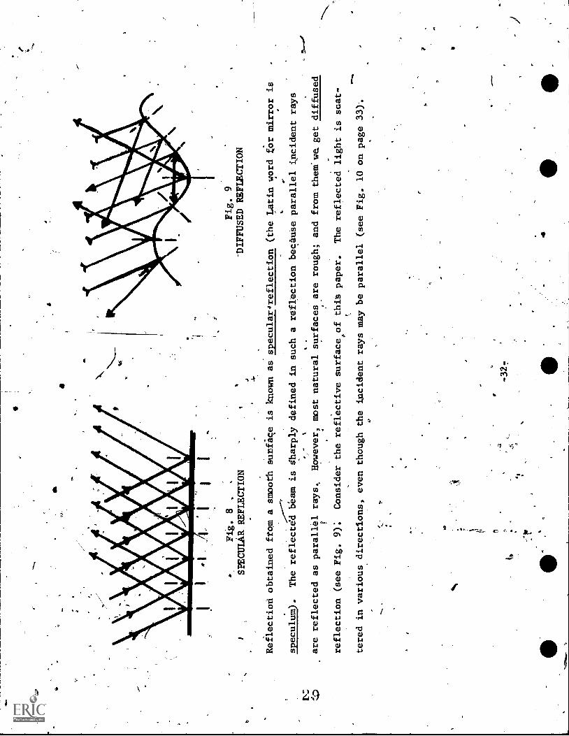
SPECULAR REFLECTION
Fig. 9
-DIFFUSED REFLECTION
Reilection obtained ftom a smooth surface is known as specular4reflection (the Latin word for mirror is
speculum).
The reflectdd beam is sharply defined in such a reflection because parallel incident rays
are reflected as parallel rays.
However, most natural surfaces are rough; and from them we get diffused
reflection (see Fig. 9):
Consider the reflective surface of this paper.
The reflected light is scat-
o.
tered in various directions, even though the incident rays may be parallel (see Fig. 10 on page 33).
f:
-32-
r
4M.

CJ
4-4
You will- need:
..
'I
Fig.-10
LIGHT SCATTERING FROM PAPER SURFACE
.
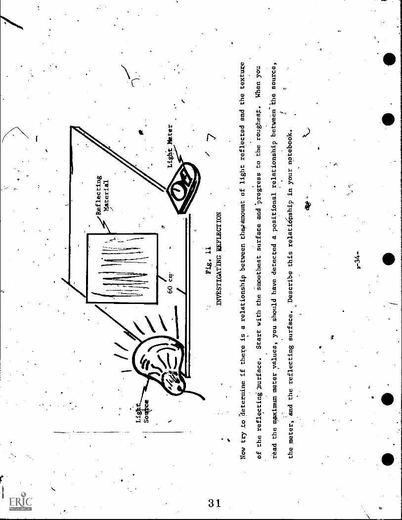
INVESTIGATING L'SPECULAR AND DIFFUSER.REFaCTION
light meter
light source and reflector
.
*
six sheets of white paper of different surface textures
,
Set up the apparatus as shown in. Fig. 11 (see page
34).
Use a darkened room, so that the
light, meter o
receives only light reflected ffom the paper.
Slowly change the reflector angle until
the light meter
value is maximum; this maximum is the value you are to
meter values for each surface in your
notebook.
-33-
iecoEd.
M.eike a data table and record the light
/Reflecting
Material
Ligh
Sotkirce
a
Light Meter
z
Fig. 11
INVESTIGATING. REFLECTION
/
Now try to determine if there is a relationship between the amount of light reflected and the texture
of the reflecting ?surface.
Start with the smoothest surface and 'progress to the roughest.
When you
read the maximum meter values, you should have detected a positional relationship between-ihe source,
the meter, and the reflecting surface.
Describe this relatiOilship in your notebook.
1,-34-
.F.4
,
INVESTIGATING PLANE MIRROR" REFLECTIONS
.YOU will need: plane mirror
ue object
Observe 'the characteristics of the object's image in a plane mirror:
l) The image appears the same size as the object.
Itb
2) Thei image appears erect (upright; not inverted).
3) The image appears as far behind the mirror as the object is in front of the mirror.
4) The image is virtual.
4.virtual image is defined as one formed by rays which donot actually
pass through the, image position. .This, means that if a screen were placed at the position of
the image (behind the wir-for), no image would be seen on the screen, because no light rays
actually get to the image position.
5) The image is reversed right to left(oerverted; this is sometimes termed a mirror image.
Notice that although Orverted, a plane mirror image is not inverted; the mirror does not
reversewr and down. 'This statement, of course, assumes a vertical mirror and the Viewer
jin the/normal uprigh
position.
,
/I
-35L-

RESOURCF\ PACKAGE 2-1.5
MIRROR, MIRROR, ON THE WALL
ARE YOU TOO SHORT?
AREJYOUTOO-TALL?
40"
imagine that you have been promoted to manage the Clothing Department
of Heiman Snarcus.
The department's
only mirror was broken by a bad image last week, and you have the taskof buying"a new mirror.
As a mat-
ter of record, it was probably good that the old mirror was
broken, because many customers complained of
its not being tall enough for them to see
themselves from head to toe.
The old mirror was 5 feet tall.
Consider that fellow stude
in this physics class
represent a cross section of the customers who would
41
,v1iit the Ctothing.Departme
Of-Heiman Snarcus's Store.
Based on such height data, what would be the
smallest mirror you would ha e to buy?
Were the customers'. complaints about the old mirror's being too
short justified?
TO SOLVE
PRBLEM:
'Draw a diagram in your notebook and use ratios, ray diagrams, orwhatever,
.mirrot and the customer's height will not be the same:- A diagram such as
he one o
page
8 migh
elp.
arriVb at a solution.
The
r
-37-

Mirror
i
.
Image plane
of mirror
Needs to see top of
A---head in mirror
I
Height
to
Eye
Needs to bee shoes
in bolrrot
Image
Floor
..
plade'of mirror
tab
Iy t
RESOURCE PACKAGE 2-1.6'
IMAGE PROBLEM
1
Imagine that the Board of Directors of Beiman Snarcuso a small discount store, promote you to work as
manager of the Shoe Department.° Also,- they increase the Department's budget by $167.73--enough to buy
two plane mirrors.
Along with this promotion, you are given the following problem:
to determine tides'
to fit together, at some angle(s), the
images ("n" image", where n
,2, 3,
Ttpartment's 4ni-computer, which will
of the, angle between these two mirrors
two plane mirrors such that they will
show
any desired number of
...) and to derive a formula that can be programmed into the
enable your employees to- determine quickly the proper setting
to produce the desired number of customer images.
If successful,
the customer will bp able to aee.as many images of the-beautiful Heiman Snarcus shoes as
.
-, feels necessary to close a sale.
HOW TO SOLVE THE PROBLEM:
Make a table in'your notebook like the
one shown on the next page.
Determine
your salesman
the angle between the two
mirrors.
Then see if you can derive'a formula stich that knowing the tangle (8), one can obtain the num-
,
tier of images (n).
Then rearrange the f9rmula so that-if one
,the angle for setting the mirror.,
-39-
knows the number of images, one candetermine'
0.
4
fl
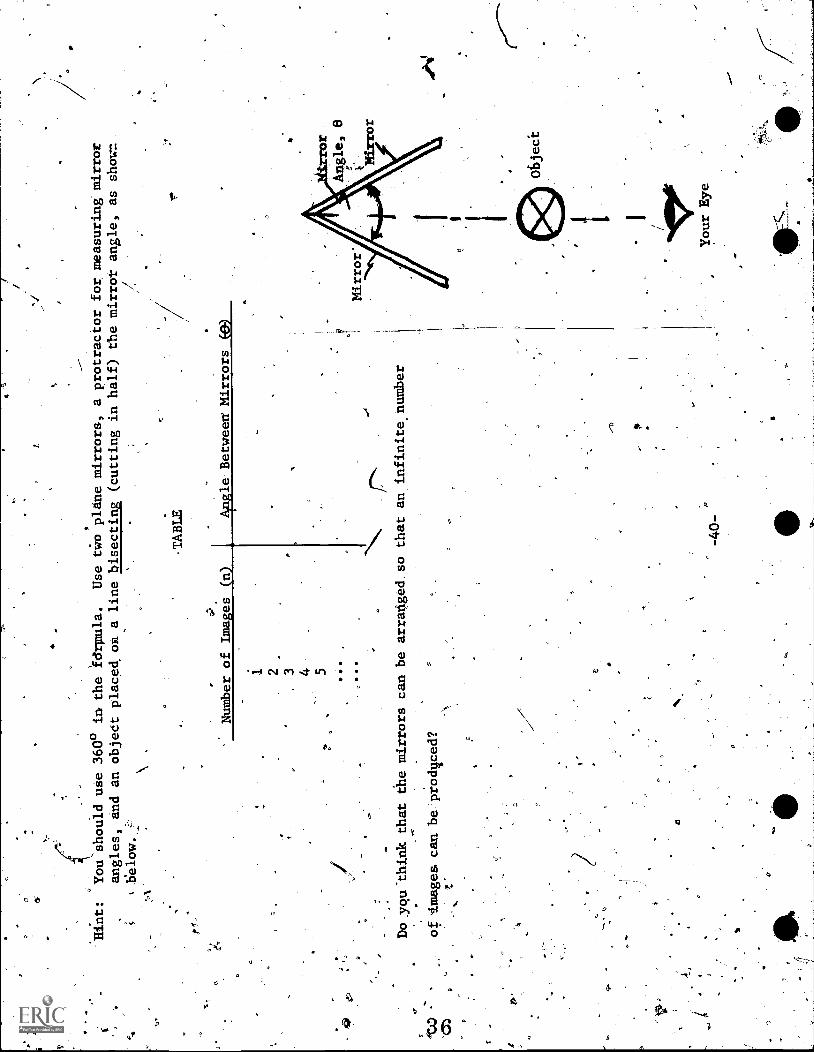
Hint:
You should use 360° in the fdrpula.
Use two pliine mirrors, a protractor for measuring mirror
angles, and an object placed OR a line bisecting (cutting in half) the mirror angle, as show:
*1.
below.-
ta
Number of Images
1 2 3 4 5
-TABLE
e Between Mirrors
Do you -think that the mirrors can be arranged so that an infinite, number
of Images can be.prodiced?
z
-40-
1
1
"1:POIC
Your Eye.
,
06jeci
RESOURCE PACKAGE 2:1.7
SOME APPLICATIONS
---
There are many careers involved in,making designs for wallpaper, fabrics, and rugs.- An instrument often
used to aid in developing these designs is a kaleidoscope.- A kaleidoscope is a mirror device that makes
use of multiple reflectidns.
/(0
A kaleidoscope consists of two plane/reflecting surfaces set at an angle and placed within a tube..
,Pieces of colored glass, or other bits of colored material, are illuminated through a translucent glass
at one end ot tpe tube; and the other end has a peephole.
INVESTIGATING THE KALEIDOSCOPE
mCYou will need the following
terials: r
cardboard tribe, alimut 2,in (5 el) diameter
aluminized film sheets, or small mirrors
clear plastic film
.-0
colored objects
about 12 in (30 cm) long
Cu
the aluminized film into two sections small enough to by taped together at a 60-degree angle andto
fit inside the entire length'of the tube (see Fig, 1 on page 42).
'In your notebook show the falculation
--
for.how many: images you will expect to see (use the formula from Resource Package 2-1.,6).
5
-41-
4

Aluminized
heet or Mirrors
Cardboard
ube
Fig. 1
*BUILDING A KALEIDOSCOPE
Over one ad of thetube,,Plade a cap with a small -hole in'the center '(peephole).
The cap for the
Oth
er.
..
end should cpnpin the colored object
'-sandwiched between an outer layei of translucent film and an
inner liyer of clear film.
The distance
etween the two films should allow thefree movement of the
.
-,--
*-"l
colored objects.
/
-----%
.
/An interesting effect can be produced by placing a lens (a bi- convex or
"burning glass" lens) in place
iN
\A
4.
,1
e
ofi:,the colo* red objects; this method "produces images of the environment.
A magician or stage
ormer
A"-
,'0
Oanloake special use of plane reflecting surfaces to achieve startling effects or to perform feats of
magic.
For exaMple, thejappearance of a ghost on 'a dimly-lit stage can be addomplished,as shown In-
,
Fig. 2 (see page 43).
-42-
/
.1

6
a
Audience L
Stage
Pane of
Glass
- -_
1111
1, 1
1111
1111
Ghost. image is
seen here.,
Opening in
stage floor
rror
F.
2
CATO
G A GHOST
Illuminated
,
Ghost Object
V
The audienbe must be in darkness and the stag! lighting must be dim to conceal the glass pane in order
Jr
for this trick to work properly.
The actors perform behind a large pane of glass, set at anangle of
45 degrees with the vertical.
Another pane of glass or mirror, set at 45 degrees, is concealedbelow
vr.
the stage or in the pit.
The "ghost" stands in front of the concealed glass; the subject isillumi-
ilk
nated and light reflects from her/him ,torathe lower sheet of 'glass, then to
the upper sheet, and then
to the audienc:
,..;
.
I.
If the lower miklectilig surface is a mirr
instead of a sheet of glass, the ghost will appear much
brighter.
The lialting.on
he stage must be
carefullysonEr4led to make the actors visible to
41e
audience ad yet keep the glass invisible.
g
$
4
I

,
4
Another' use of pl
mirrors is to show a head4on a platter.
Two large mirrors, a platter with a hole
large enough for-"Some
's head to fit
rpugh, a three - legged table, and a stage pro erly fitted with
if
drapes are all you need
or this trick.
The two mirrors are, fitted in pla e at
-eAtas are concealed by the legs of-the table.
The drapes .axe kung so tn
they reflect in the mirrors
ap
and "so that they seem to blend in with Similar drapes in the background.
The
an angle so that-
.
looking through the legs of `the table, at tie background drape The subject, moosehead is to be pre-
audience thinks they are
.
,sented to the audience, is concealed behind/the mirrors.
She/h1pus her/his
hea
through the hole
in.
aI
thacplatter before the scene is prese4ed to the audience.
With the
roper effec
a34 acting, the'
results can be gruesome and impreasive,ewhen the
curtains are- drawn
L.
In your notebook sketch the olehead-on=a-platter trick.
Use the old ghostAon-a-stage trick as a guide.
41.
t 44
6
.r

RESOURCE PACKAGE 2-2.1
INFLECTION EXERCISE
Using the figure below, see if you can answerthe fallowing questions. 'Write your answers in your note-
.
book.
1)
The incident ray is line
2)
The normal is line
.
3)
The reflected ray is line
4)
The angle of incidence' is
r.
5)
The angle of reflection is
.6)
List-some propeKties of the image.
-45-
Mirror

4
1)
AB
'
2)
DB
3)
BC
4)
ADD, or-e-
5)
DBC, or
RESOURCE PACKAGE 2-2.2
ANSWERS
6) ,virtual
erect (upright)
perverted (reversed left and right)
same distance behind mirror as subject
is in front
-47-
0

ts
You will need the following:
cylindrical mirror
wooden drawing board
drawing compass
ruler or straight edge
straight pins
RESOURCE-PACKAGE 3-1.1.
,
CURVED MIRROR INVESTIGATION
Place the curved edge of a curved mirror
on a flat sheet of paper, with the curved
surface facing you./ Trace the outline of
CO.
the mirror on the paper and locate the
You Eye
Pin
A/14
Fig. '1
INVESTIGATING A CURVED MIRROR
Curved Mirror
middle of the arc.
Using a compass, locate the center of curvature and mark-it "G."
Draw a line through
C and the middle'of the outline of the mirror.
This line is on what is called the mirror's principal
axis.
Locate the principal focus and label it "F"; this is the point where incident parallel light rays
will focus.
At a point beyond the center of curvature (C), draw a short line perpendicular to tae, prin-
.
cipal axis; plade a pin at-this spot and label the spot "A"(see Fig. 1, above). 43), sighting along the
edge of a ruler, lOcate the image of the'pin (see Fig. 2 on page 50).
Draw a straight line and repeat
the process on the other side of the pin.
Extend the sight line to intersect with the principal Axis;
this is the location of the image.
If intersection does not occur on the axis, repeat your sightings.

You have been workin
with what is called a con-
verging mirror.
What can you say about the
locati
and nature of the image?
Next, draw a horizontal arrow across a folded
Oeet of paper about 2 cm long; place the paper
where the pin was- located, with the arrow facing
the mirror.
OhAteVe the image and compare it
with the object (erects -inverted? -smaller?
same size?
larger?)
Img.
......
Ara
4
INVfsSGATING A CURVED MIRROR
Now
the pin between points C and F.
lake
Fig. 2
sightings.on both sides of the'principal axis and
111
locate the image as before.
Next, place the horizontal arrow at this new point and determine the charac-
.
teristics of the image.
Do the same for a location between the principal fo
s and the mirror.
Record
..
,
your observations in your notebook; make a chart similar to the-ipe on page 51.
/-
O
-50-

CHART
iit
J-
Location of Object
-Baal
or
Virtual
Location
Inverted
or
Erect
Equal Size,
Larger, or
Smaller
Beyond C
Between F and C
Between F and Mirror
..
416
This time turn the mirror around so that it operates as a so-called diverging, virror.
Locate the prin-
cipal axis, the center of curvature, and the principal focus.
Draw an arrow on the principal axis on
the curved side of the mirror.
Place 'a pin at the head of the arrow, and make
sight lines on both sides
9f the principal axis.
Then place the pin on the tail of the arrow and repeat the same procedure for
making sight lines.
After removing the pin and mirror, extend the sight lines for*each pin position until
they'meet.
Draw
the image that represents the arrow through these two points.
In your notebook, describe what you ex-
pect will happen to the genefal characteristics of the image as the distance of
the object is changed?

RESOURCE PACKAGE 3-1.2
T.
CURVED MIRRORS
A reflecting surface need not be flat to exhibit specular reflection.
must be smooth.
mirror can be curved, but it
The law of reflection for a single ray is the same for curved mirrors as it is for plane mirrors.
Pw-
ever, the overall effect of a number of parallel incident rays can be quite different.
Curved mirrors
do not have the same imaging properties as plane mirrors.
Parallel rays reflected from a curved sur-
face are no longer parallel.
If the reflecting surfaces are spherical, the reflected rays of light
either converge to a single point or diverge away from the reflecting surface.
Thus, curved mirrors
are claisified as-either converging or diverging mirrors..
Curved mirrors usually take the -shape of a sphet
pe, a'araboloidan ellipsoid, or a cylinder.
All such
mirrors have Converging_or diverging properties.
-53-
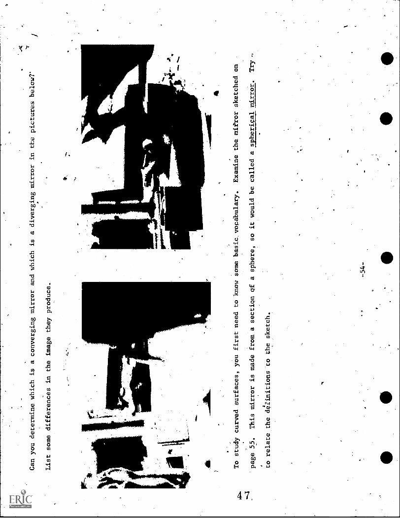
Can you determine which is a converging mirror and which is a diverging mirror in the pictures below?'
List some differences in the image they produce.
0.6.
4114
011.
To study curved surfaces, you first need to know some basic.vocabulary.
Examine the mirror sketched on
page 55.
This mirror is made from a section of a sphere, so it would be called a spherical mirror.
Try -
to relate the definitions to the sketch.
z
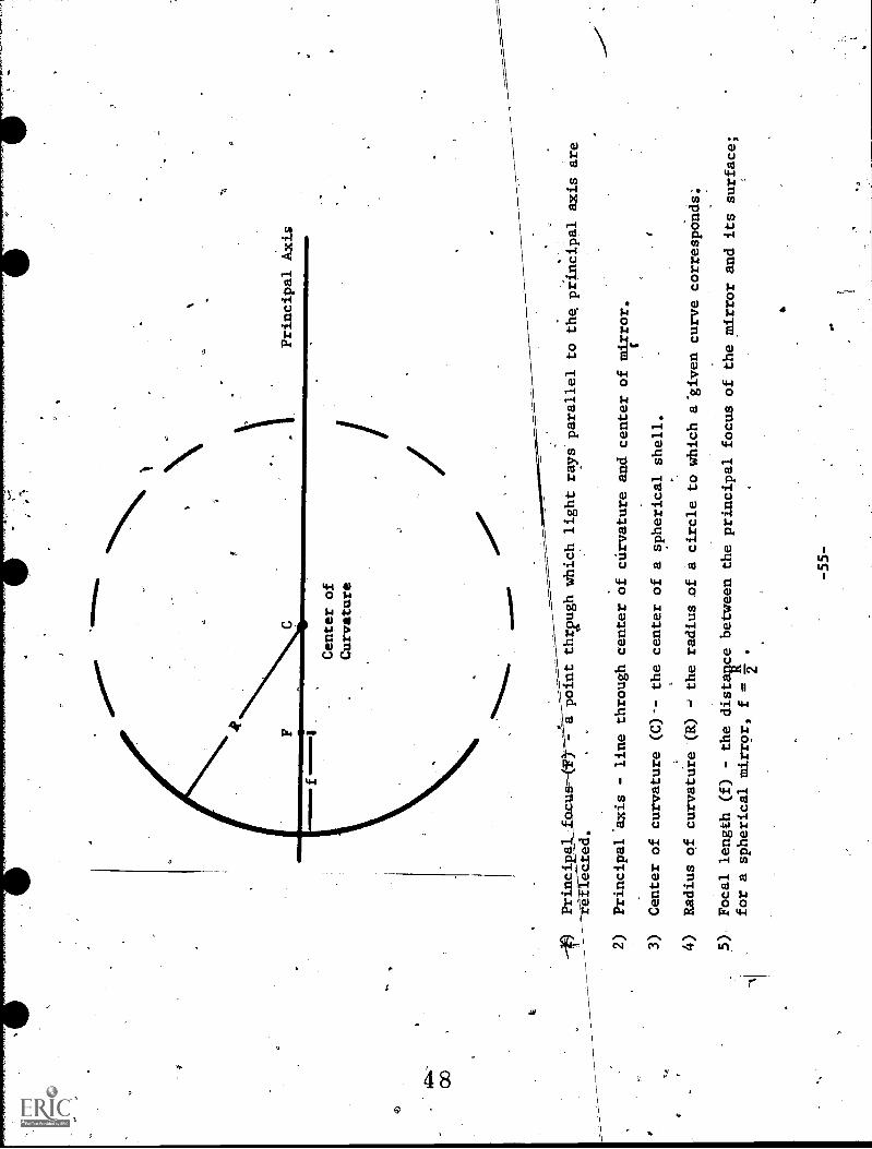
Center of
Curvature
Principal Axis
Principal
a point thr2ugh which light rays parallel to the principal axis
are
eected.
,
2), Principal'axis - line through center of curvature and center of mirror.
3)
Center of curvature (C)*- the center of a spherical shell.
4)
Radius of curvature (R)
the radius of a circle to which a'given curve
corresponds;
5)
Focal length (f) - the distaRce between the
principal focus of the mirror and its surface;
for a spherical mirror, f
.
6)
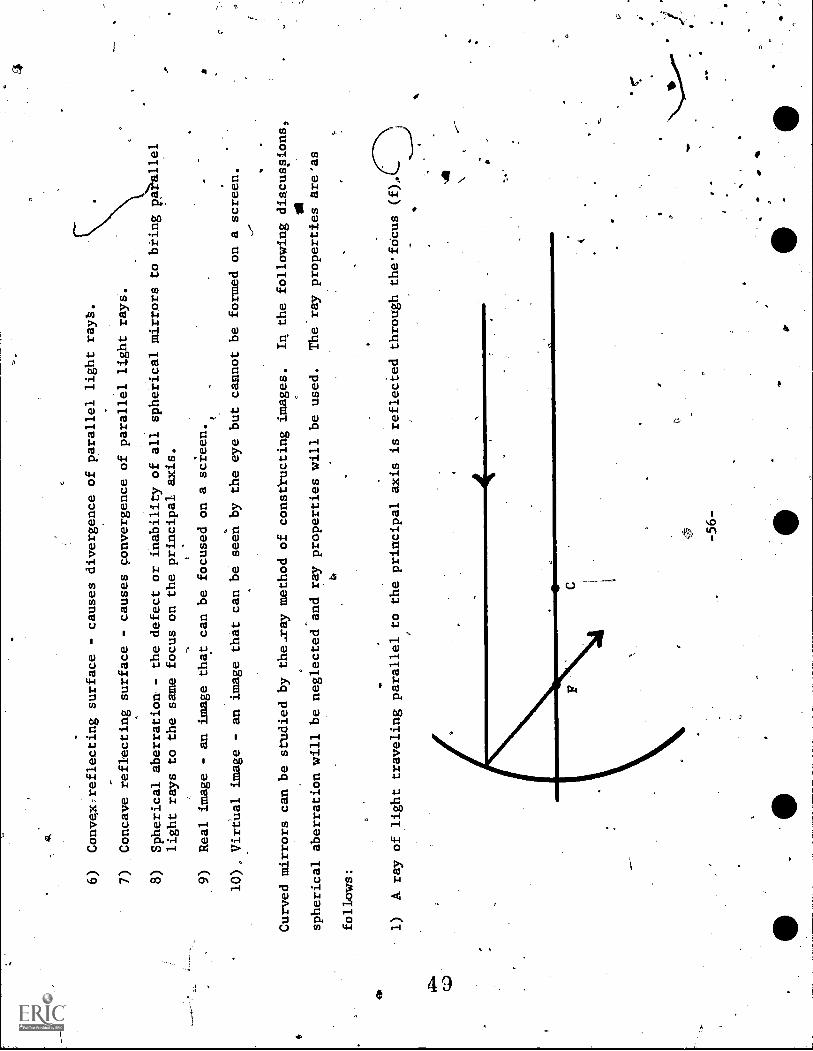
Convex:reflecting surface - causes divergence of parallel light raya.
7)
Concave reflecting surface - causes convergence of parallel light rays.
8)
Spherical aberration - the defect or inability of all spherical mirrors to biing
light rays to the same focus on the principal axis.
9)
Real image - an image that can be focused on a screen.
a
10)., Virtual image - an image that can be seen by the eye but cannot be formed on a screen.
Curved mirrors can be studied by the.ray method of constructing images.
In the following discuspions,
IN
spherical aberration will be neglected and ray properties will be used.
The ray properties areas
follows:
1)
A ray of light traveling parallel to the principal axis is reflected through the'fOcus
-56-
41
C

C.,71
C.)
2)
A ray of light which passes through the center of curvature (C) and Which is incident perpendicular
to the mirror's surface, is reflected back through C.
.4
-57-
II
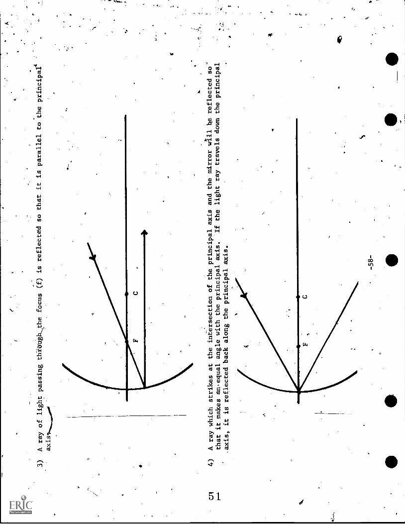
3)
A ray of light passing thibughthe focus (f) is
so that it is parallel to the principal`
axis
(a-
C
4)
A ray which strikes at the intersection of the principal axis and the mirrorwill he reflected so=
that it makes an.equal angle with the principal axis.
If the light ray travels down the principal
,axis, it is reflected back along the principal axis.

The intersection of all (or even of any two) of the reflected rays locates
the image point; see how
these rays can be combined, as in the sketch below:
*
Experiments show that the
distance of the object (dd) and the distance of the image (di) from the mirror,
the size of the object (So) and size of the image.(Si), and focal length
are related as follows:
11
4.
1
do
di
acid
So =do
Si
d- i

These formulas can be arranged to find the following properties, when others are known:
1)
distance of object (do)
do =
di x f
di - f
2)
distanc
of image (di)
A. _
dox f
1do - f
do =
So x di
Si
di _Six
d0
So
A negative (-) di.represents an image on the other side o
the inirror.
3)
foCa1 length (f)
1 . do + di
fdo x di
4)
size of object (S0)
So
dox Si
di
AP
size of image (Si)
d-
SSi _ 1xo
do
-60-
.6

Example Problem 1:
o
A converging mirror whose focal 'length is 20 cm is/placed
30cm from an object which is
4.0 cm high.
Calculate the location of -the image (di) and the height bf the image (Si).
fr 20' cm
do = 30 cm
Sq = 4'.0 cm
di = ?
Si = ?
CR
ddo x f
1do - f
3e&
lax 20 cm
30 em
20 cm
J
=600 cm
xcm
10 cm
di = 60 cm
'_ 240 cm
kcm
20 cm
12 cat
di = 60 cm
20 cm
Object
11{
t4 cm = Image Height
-Image
Thus,,t-he image is 60
CM
from the mirror and is enlarged to a
.height of 12 cm.
(Yetshould always diagram a problemsolution
of this kind, as was done above.)
v
-61-
e
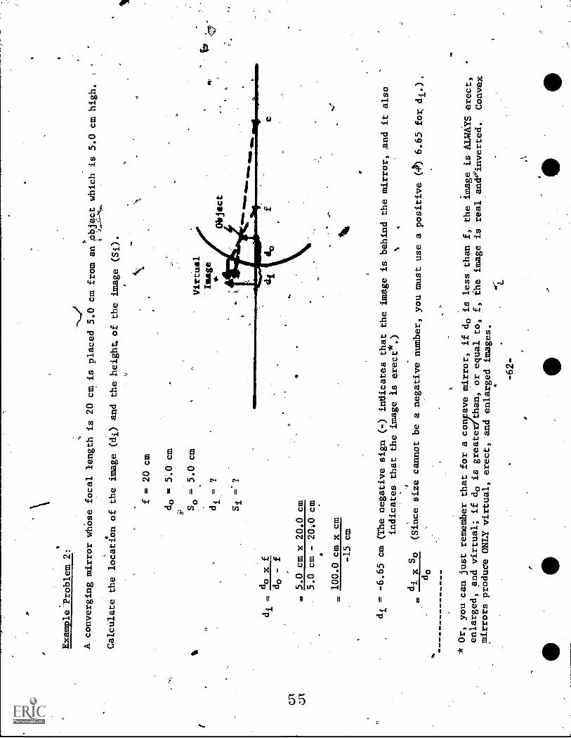
Example Problem 2:
A converging mirror whose focal length is 20cm is placed 5.0 cm from an object which is 5.0 cm high.
Calculate the location of the image (di) and the
height, of the image (Si).
O
f = 20 cm
do = 5".0 cm
So = 5.0 cm
di = ?
si ='?
di . do x f
do - f
= 5.0 cm x 20.0 cm
5.0 cm - 20.0 cm
=100.0 cm x cm
-15 cm
Virtual
t.age
*Object
OP
C
di = -6.65 cm (The negative sign (-) indicates
that the image is behind the mirror, And it also
indicates that the image is erect*.)
di x So
(Since size cannot be .a negative number,
you must use a positive (4) 6.65 for di.),
do
* Or, you can just remember that fora consave mirror, if do is less than f, the image is ALWAYS
erect,
enlarged, and virtual; if do is greaterfthan,
or equal to, f, the image is real aneinverted.
Convex
mirrors produce ONLY virtual, erect, and enlarged
images.
4
-62-
0
.6.65 cm X'5.0 cm
5.0 cm
=33.75 cm x cm
5.0 cm
So = 6.65 cm
Therefore, the image is 6.65 cm behind the mirror and the image is
enlarged to a height of 6.65 cm.
C
4
-63-
aP
RESOURCE PACKAGE 3-1.3
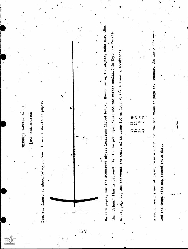
4RAY CONSTRUCTION
Draw the figure as shown below on four different sheets of paper.
-Or
On each paper, use the different object locations listed below.
When drawing the object, make sure that
the "object" line is perpendicular to the principal axis; use the method outlined
in Resource Package
4-1.1, page 47, and construct the image of an arrow 3.0 cm long at
the following locations:
1)
13 cm
2)
11 cm
3)
8 cm
4)
2 cm
Also, on each sheet of paper, make a chart like the one shown on page 66.
Measure the image distance
and the image size and record these data.
-65-
a
a

Data
Measured
'Calculated
Focus
6 cm
Distance of Object
cm
Distance of Image
,cm
Size of Object
-3 cm
Size of Image
cm.
.
Erect or inverted image larger
or smaller than object
.
.
CHART
Then, on each sheet, calculate the image distance and image size.
Record these data.
How well do the
calculated and diagrammed-values compare?
r"r
1
-667
4

RESOURCE PACKAGE 3-1.4
CUSTOMER SATISFACTION.
Imagine that.you have been promoted to Assistant Vice-President in charge of Store Security for Beiman
Snarcus.
Several of the store's prominent custoders have complained that the store security mirrors "bulge out"
at them like eyes.
They are not complaining about the mirrors' presence, but about their shape.
Your
boss, considering the.Beiman Snarcus tradition of "customerskisfaction," is thinking about changing
the shape of the mirrors; but before making a decision,-she has assigned you the task,of writing a re-
.
port on the differences between "bulging out" (convex), "straight" (flat), and "bulging in" (concave)
mirrors and the passible effects upon store security if the "bulging out" mirrors are replaced by dither
ft
-of the other two kinds:
When you have completed this reporti show it to your real boss (your instructor) and await the decision.

RESOURCE PACKAGE 3-1.5
CURVED MIRROR USAGE
A
There are more purposes for which curved mirrors areused than there are for plane mirrors.
List as
many common uses
of curved mirrors as you can think of and record whetherthe mirror is convex-or con-
cave.
Also
make a list of occupations that utilize curved mirrors..
(Should you not know where to
find this information, ask your instructor to help you.
He/she can suggest several references.)
2,
Or
-69-
( 5
RESOURCE PACKAGE 3-1.6
THE OLD LIGHT- BULB -IN- THE - EMPTY - SOCKET TRICK!
Knowing the properties of curved mirrors; you canperfor6aFfollowing tyick.
A concave mirror is
,
used to project a real image of_a light bulb that 'is concealed upside
down in a box (see Fig. 1 on
s
page 72):
The image is forbed over an empty.light socket on top,of the box.
With the room properly darkened,
4o;
the audience sees a real light socket and also the image of the
concealed bulb.
The illusion fools
many into thinking that an actual light bulb is in the
real, but empty, socket.
The performer can
even hit
this _light bulb image w*th >yammer; but, of course, the "bulb" will not shatter.
CD
-
'ft
-71-

V11
.,-,
Image of light and
socket appear right
side up
Concave Mirror
Box with hole
4
-Fig. 1
THE OLD LIGHT-BULB-IN-THE-EMPTY-SOCKETTRICK
Lighted bulb hanging
inside box at center of
curvature of mirror

)
RESOURCE PACKAGE 3-2.1
CURVED MIRROR EXERCISE. I
1.
Look at the diagram above.
In your notebook, write down the identity of thenumbered items in the
diagram.
1)
2)
3)
4) 5)
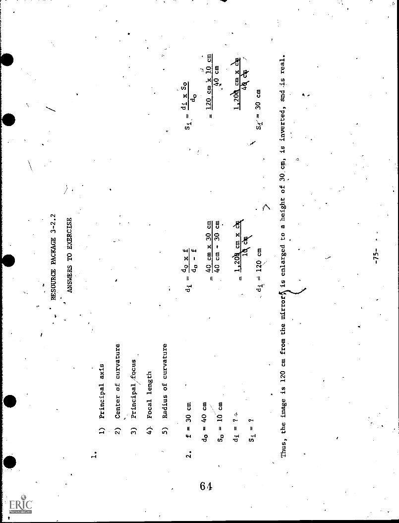
2.
A converging mirror wittYa focal length of 30 cm is placed 40 cmfrom an object which is 10 cm
high.
your notebook, calculate the location of the image
(di), the height of the image (Si),
and fur
r describe the image.
-73-
1)
Principal axis
2)
Center of curvature
3)
Principal
cus
4)-
Focal length
5)
Radius of curvature
2.
f = 30 cm
CD
do = 40 cm
So = 10 cm
di = ?
Si = ?
RESOURCE PACKAGE 3-2.2
ANSWERS TO EXERCISE
dQxf
do - f
=40 cm x 30 cm
40 cm - 30 cm
di x So
do
= 120 cm x 10 cm
40 cm
1 20
4
,di = 10 cm
Sri-= 30 cm
(
Thus, the image is 120 cm from the mirror, 1
is enlarged to a height of 30 cm, is inverted, and.is real.

S
RESOURCE PACKAGE 5-1.1
;REFRACTION I
Look at Figures 1 through 9.
In your notebook, explain simply why the penny appears and
then disappears.
This phenomenon ("happening") is.known as
refraction.
1
As. I
Fig. 2
3-
0101
1111
.1'.'
"""1
1614
4 ft
Fig. 3

kkkk111.1k 4
;
k
1
I
0'

. *
6 -2T3
O
-6L-
we*
=$
O
Z..
Read about refracs, on in a textbook.
Consult your teacher about the recommended sections to read.
(If you have Physics,,A Basic Science, read pages 227-230.)
Also, read abOut refraction in any three
of the references listed below:
0
S. O
O
O
Compton's Encyclopedia
World Book Encyclopedia.
EncyclopediaBritannica
Encyclopedia Americana
Encyclopedia of Science and Technology
-80-
O

RESOURCE PACKAGE 4-1.2
REFRACTION II
From your reading of'Resource Package 4-1.1, you should be able to complete the foll6wing exercises.
If
you should have trouble, review your'readings and/or perhapq consult your instructor.
Write your responses
in your notebook (please, NOT IN THIS BOOK).
1)
The refraction of light is a.(bending, bouncing)
from one medium into another.
t.
of light as it passes
2)
In the figure above, the direction of light is (A to B;o13 to A; impossible to determine from
the data given).
Select one of these as an answer.
.
3)
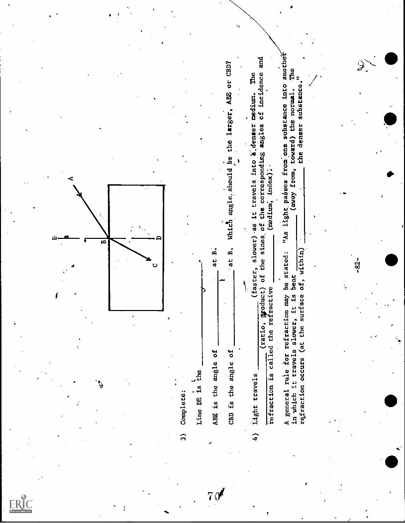
Complete:
Line DE is the
ABE is the angle of
at B.
CBD is the angle of
at B.
Whict angle,should be the larger, ABE or CBD?
4)
Light travels
(faster, slower)-as it travels into a,denser medium.
.The
(ratio, Aroduct) of the sines -of the corresponding angles of incidence and
refraction is called the refractive
(medium*, index):'
A general rule for refraction may be stated:
"As light,,paeses from.one substance into anoth
in which it travels slower, it is bent
(away from, toward) the normal.
The
refraction occurs (at the surface of, within)
the denser substance."
-82-

5).
Ar3Cenge the following in the order in which light travels the fastest:
a)
water
b)
Lucite
c)
diamond
TO
gasoline
e)
vacuup
f)
ice'
g)
curved glass
C
6)
Using atprotractor, measure the angle
incidence and'angle of refraction for-each of the
following drawings.
List your measurements in tabular form in your notebook.
Data
Number of
,Drawing
Angle of Ipciderice
_
.
Angle of Reflection
.
--)
r
N..
-83-

a
- 72
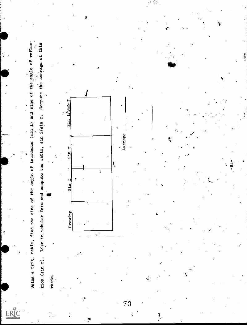
Using a trig, table, find the sine of the angle of incidence (sin i)' and sine of
the angle of reflec- .
.T
tion (sin r).
List in tabular form and compute the ratio, sin i/sin r. -Compute the average
of this
ratio.
Drawing
Sin i
Sin r
Sin i/SluT
,.. -85-
Average
.0*
1
a
)
r.
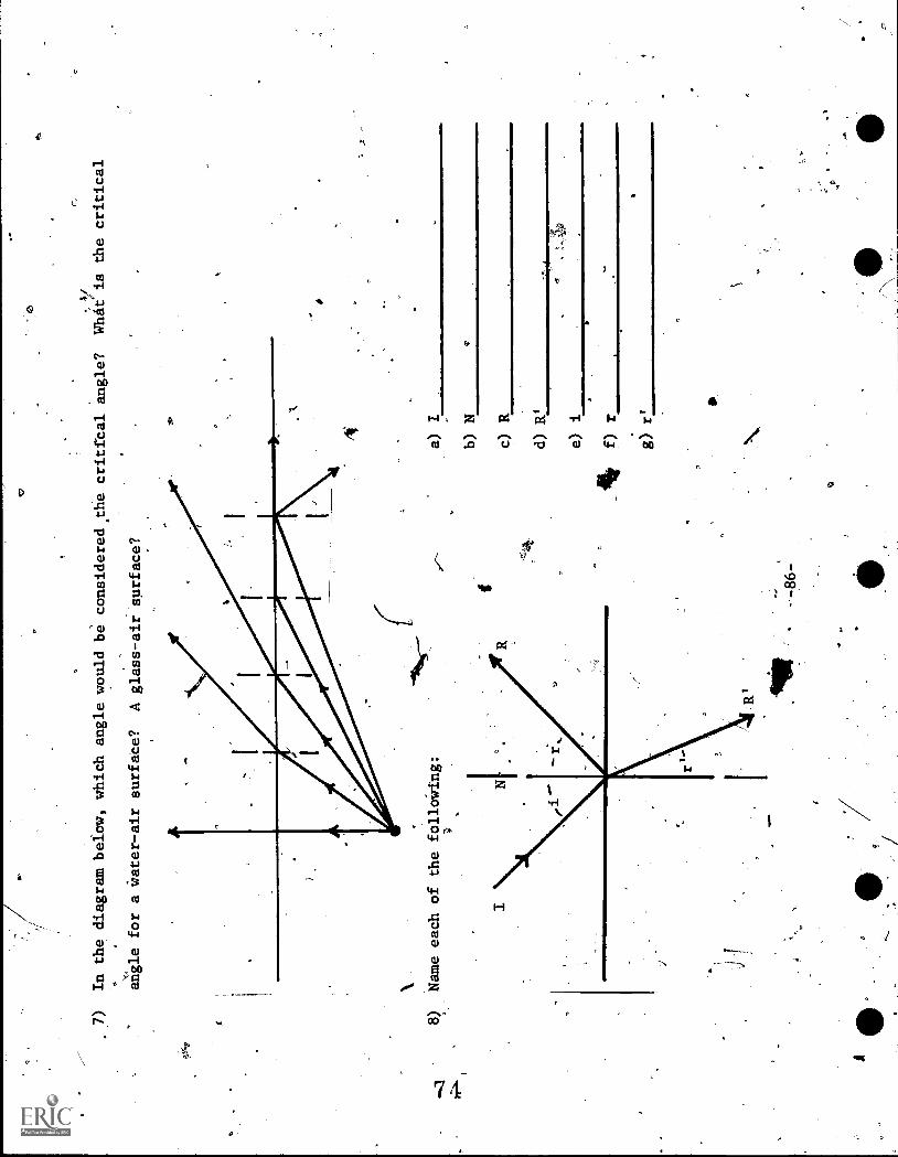
In the diagram below, which angle would be considered the critical angle?
Wluijiis
the critical
angle for a Water-air surface?
A glass-air surface?
Name each of the folloWing:
a) I
b) N
c) R
d) e) i
14f) r
,
girt

A
4
a
9)
Cllhat two people can be credited with discovering the laws of refraction?
10)
Draw your own diagram andlbeinplete the path. of. the ilicident,ray, I, across the various trans-
parent layers shown.
Air
Water (n = 1.33)
Carbon Dioxide (n = 1.0005)
Glass (n = 1.50)
Alcohol (n = 1:36)
11)
Draw your own diagram and complete the path of,the ray of light indicated in the drawing.
The-ray passes into alcohol, is reflected from a plane mirror, and finally emerges into air
again.
O
kg
11,
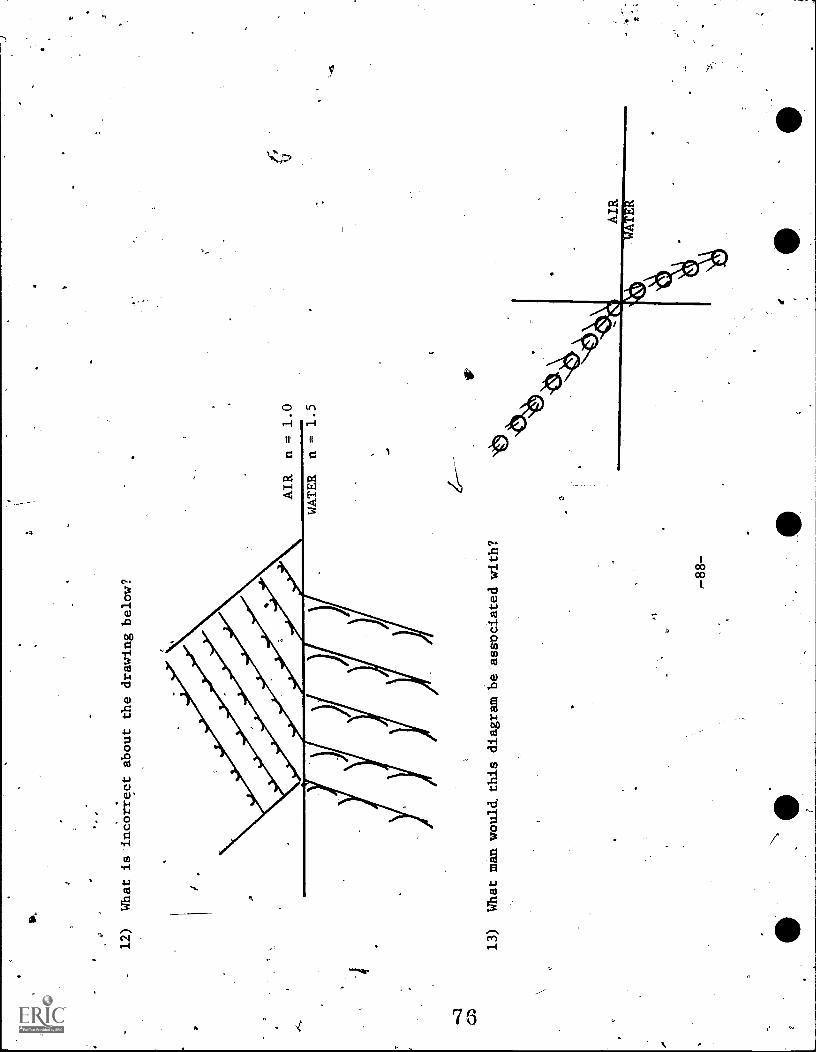
12)
What is incorrect about the drawing below?
13)
What man would. this diagram be associated with?
AIR
n = 1.0
WATER
n = 1.5
4.

14)
What man would this diagram be
associated with?
.01
15)
Complete the path of the rays shown.
Draw and label all normals and rays at each surface._
ti
-89-

16)
Complete the path of the rays shown.' Draw and label all normals and
calculate all angles.
\_--
17)
The
dex of-refraction can be expressed as the ratio of
speed of light in a vacuum (c) and
the speed of light in a medium (v).
The index of refraction of a diamond is 2.42, The
speed
e
,of, light in it ip
m/sec;
0
a
C-90-
a

AN
You will need:
/
Rectangular glass plate/
Wooden drawing board'
Drawing compass
Ruler
Straight
Lige
V
RESOURCE PACKAGE 4-1.3
INDEX OF'REFRACTION
Place jrectangular glass plate on a line drawn on'a sheet of papdr.
Look at the line through the
.0
glass; view the line from-different angles.
Describe the appearance of the line as the view angle is
changed.
Place the glass plate on a different sheet of paper and
draca.Loharp
pencil line around the glass.
Place two pins back of the glass but not in a line perpendicular to the edge of the glass.
With a
.
ruler in front of the glass plate, sight along the edge of the ruler until the edge is.dirdctly in,
e="
line with the two pins.
Draw a pencil line along the edge of the ruler (see picture above).
After
a
-91-
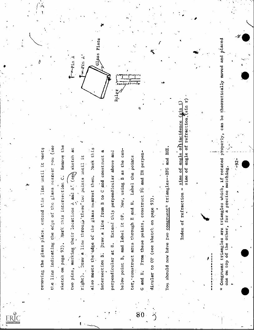
removing the glass plate, extend this line until it meets
the line indicating the ed2e of the glass nearest :You (see
sketch on page 93).
Mark_ this intersection C:
Remove the
two pins, marking their locations A and A' (spe sketch at
1N-Pin
A
right).
Draw a line throuthese two points until it
also meets the'pdge of the glass nearest them.
Mark this
intersection B.
Draw .a line from B to C'and construct a
perpendicular at B.
Extend this perpendicular above and
below point B, and label it OP.
Now, using B as the cen-
ter,.construct arcs through E and H.
Label the points
00
aG and H.
From these points, construct FG and EH perpen-
dicular to OP (see sketch on page 93).
You should now have two congruent* triangles--BFG and BHE.
Rul
Index of refraction
sine of angle a)incidence
i)
sine of angle of refraction,(sin r) -
ti
* Congruent triangles are triangles which, if rotated ftdperly, can be theoretically moved and placed
one on top of the other, for a precise matching.
1.

O
Pin Position A
Point G
Pin Position A
3
Arc
GPoint F
0
Point
erpendicular FG
oint B
Arc H
oint E
erpendicu
er
P
-93-
oint
Lar EH
C
endicular Line OP

Label the angle of inci4ence, "i," and the angle
of refraction,\nr."
Thus, Index of Refraction =
Sin i =
FG
BG
Sin r = EE
BH
FG/BG
EH/BH
FG
EH
Since BG,and BH are equal (hypotenuse of congruent triangles),
the index of refraetpmr=
Now, measure FG and EH Carefully.
FG
EH
(Try to read as close to tenths of a millimeter
as possible).
Record
the data in your notebook ,in a chart similar
to the one on page 95/ Then compute the index of reffac-
tion of the glass and compare it to the &ctual index of
refraction (the agtualindex can be found in
a*
o.
table; crown glass is 1.50; water is 1.33, etc.)
roO
dr
-94-

00 CO
r
Data
Length of FG
Length of EH
-Index of refraction calculated
Actual index of refraction
Last, answer these questions in your notebook:
45
Questions
1) ,HoW many times was the light ray bent as it passed through
the glass?
2)
At what point(s) were the light ray's bent?
43) 'Is there a similarity between the angle'at which
the light enters the glass and the angle at
which.light-leaves.the glass?
4)
Is light'bent toward or away from the perpendicular as
it passes from air into glass?
From
Pglass into air`?
-95-

RESOURCE PACKAGE 4-1.4
ATMOSPHERIC REFRACTION
At sunrise or sunset the position
of the sun's disc_affears-abotrejbiactual location of the sun by
about 0.50
.-The sun's spherical shape also appears
flattened.
From your study of the refraction
of
2
light as it passes through different
media, can you explain the phenomena?
Use diagrams, and answer
in ylur notebook.
An qually interesting study is to
determine whether the moon is
really larger'as it rises on the hori-
zon/(it appears to be larger) than when it is
ditectl
overhead.
Pho
raphs of the moon when it is
overhead show diet the two images have
identical size and shape.
This
henomenon of an enlarged goon
is CoMmonly called the "moon
illusion" and is partially. accounted. for by atmosphericrefraction.
-97-
N.
RESOURCE PACKAGE 5-1.1
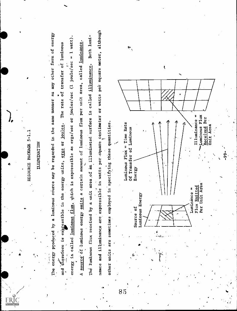
ILLUMINATION
The energy produced by a luminous source may be regarded in the same manner as any other form of energy
and the're'fore is eimessible in the energy units, ergs or
'off ules.
The rate of transfer of luminous
4.
energy, is called luminous flux, which is expressible as ergs/sec or joules/sec (1 joule/sec = 1 watt).
A sourceof uminous energy emits a certain amount of luminous flux per unit area, called luminance.
The luminous flux received by a unit area,of an illuminated surface is called illuminance.
Both lumi-
nance and illuminance are expressible in watts per4quare centimeter or watts pei square meter, although
other units are sometimes employed in specifying these quantities.
CC
-e
Source of
tE
Luminous Energy
Luminous FluX = Time Rate
Of Transfer of Luminous
Energy
Luminance =
Flux Emitted
Per Unit Area
-99--
Illuminance =
Luminous Flux
Received Per
Unit Area

G.
k
.-
-A unit of
id;mfnousflux Is the luben., Let'us first consider luminous intensity, and then return to the
lumen.
For many years.lnminous intensity was the'quantity that served as the basis for all' light mea-
surement.
The standard for intensity was the standard candle. 'The standard candle was a candle of
sperm wax burning at a rdte of 120 grains
hour- We can tHink of the candle as the center of a
,
unit sphere, and the total flux emitted by the standard candle was 12.56 lumen:
-
The standard candle, could not easily be precisely reproduced and was soon replaced by a group of carbon
filament lamps operated at a carefully prescribed voltage.' Such carbon lamps are still maintained at
..
the National Bureau of Standards and constitute,vrimary standards for intensity. -A more modern standard
candle slightly smaller than the old has been adopted for international use.
This new standard candle
is based on the luminous intensity supplied by the surface of a theoretically perfect abSorber and per-
,
OD
fecte ter of radiation at the temperature of freezing platinum (2046° K).
The new international
candle is defined as 1/60 of the luminous intensity of a square centimeter supplied by this perfect
body.
Beat-Use luminous flux is tir time rate af transfer of luminous energy, if you multiply this rate by
the p4iod af time over which it is maintainedr the 'result is the total luminous energy transferred
3
(lumen-seconds).
If the average luminous flux of a lamp is 33 lumen and the Adze forrwhich the light
is turnedanis 30 minutes, then the total energy emitted will be 33 lumen x 30 minutes x 60 sec/min,
or 55,.400 lumen-seconds.
I
-100-
O
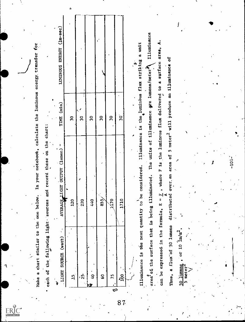
Make a chart similar to the one below.
In your notebook, calculate the luminous energy transfer
for
each of the following light- sources and record these on the
chart:
_LIGHT SOURCE (watt)
AVERAGE .LIGHT
OUTPUT (lumen)
TIME (min)
LUMINOUS ENERGY (1m-sec)
1.5
.
.
'1
r
120
30
2220
30
.,, '`
______
440
.440
30
.
.
60
..
855
30
,.,,.
.-
75
.
.70
.30
.
100
__---
1710
.30'
q'
Illuminance is the next quantity
tolbe considered.
Illuminance is the luminbus flux striking a unit
V-area'of. the surface that is being illuminated.
The units of illuminance ore lumens/meter
Illuminance
can be expresse& in the formula, E = F ,
where F is the luminous flux delivered to a surface area,
A.
AThus, a fluxof 50 lumens
distributed over_an area of 5meter2 will produce an illuminance of
50:lumens
,or 10Im/m2.
5 meters
-101:

V.
Unit Solid Angle
.
, The meaning of illuminance can be seen in the drawing above. A is a point source of light of 1-candle
intensity producing a 11-Ux of. 1 lumen per unit solid angle*.
If a sphere is 1 foot. in radius and is
,
-';drawn with the ` source as the center for a unit solid angle, the area cut out of the spherical surface
ry
will.be 1 ft2. 'likewise, in
a sphere of 1 meter radius drawn about A, a unit solid angle will intercept
..
_-Area of 1 m2
. -The illuminance in the first case, is therefore 1
lmlft2, and in the second, 1 lm /m2.
DoesalIdminfinae vary with the= intensity of the light source?
MAke a chart like the lee below in your
nOtebook.
e the fozimula for illuminance, E =
calculate`
and calcUlat
the E values necessary to complete
the chart.
4o
* It
urns outJirOmisolid (spherical). geometry that there are "411 solid angles" in every spheroid.
.
ff
v
-102-
J3
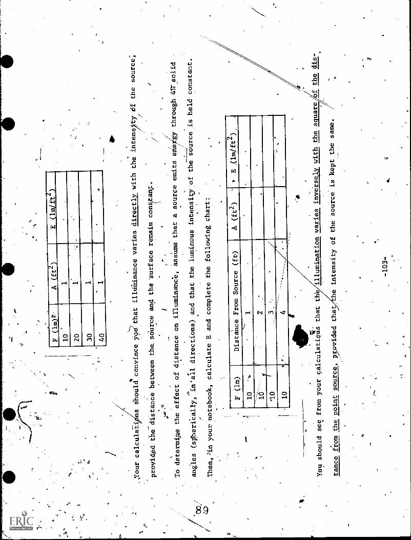
F (1m)9:
A (ft2)
E(lm/ft2.)
10
20
1'
30
1.
40
1
.
Your calculaii ns Should convince yoerthat
illalinance varies directly with the intensity
lel the source,
r
provided the distance between the sOurce and the'surface remain cons(tanp.
i.
t-
/
To determine the effect of distance on
illuminance, assume that a source
through 41r solid
.
..
.
angles (spiherical/y,
,
in'all directions) and that the luminous intensity of the source is held constant.
Then,in your notebook, calculate E andcomplete the following chart:
F (lm)
Distance From Source (ft)
A (ft2)
wE ,(1m/ft2),
10
-%.
,,..
10
2,
.
'10
93
10
4A
.-
111101
-You should see from your calculation s
that th.
illumination varies inversely with the
squareJ,bf the dis
a.
tance from the point source, pvided
tha
the intensity of the source is kept the same.
-103-
Ai
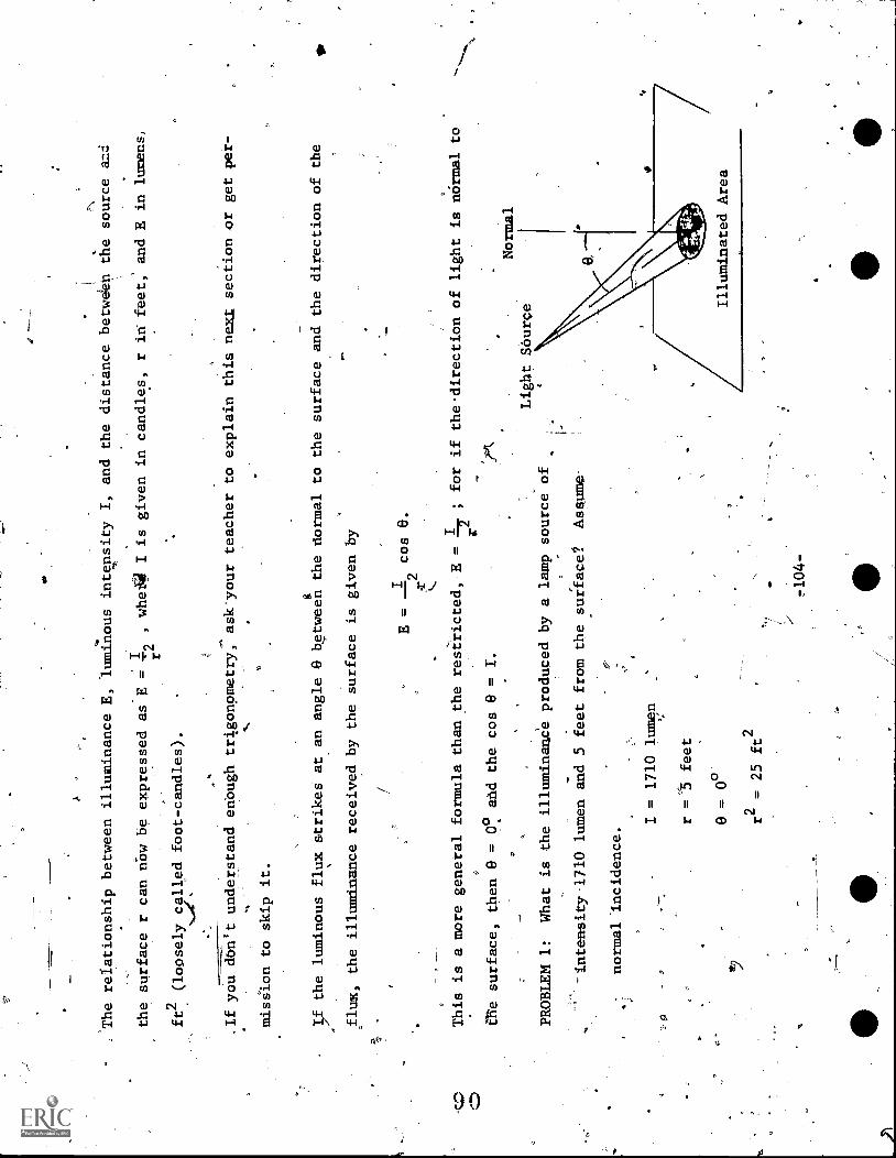
The relationship between illuminance E, 'luminous intensity I, and the distance betweieh the source
the surface r can now be expressed as B = I2
, whe
I is given in candles, r in feet; and E in lumens,
ft2 (loosely called foot-candles).
,If you don't understand enough trigonometry, ask'your teacher to explain this next section or get per-
mission to skip it.
If the luminous flux strikes at an angle 9 between the normal to the surface and the direction of the
flux, the illuminance received by the surface is given by
E = -I -
2cos 9.
This is a more general formula than the restricted, E =
fie surface, then 8 = 0° amid the cos 8 = r.
I.for if the-direction of light is normal to
PROBLEM 1:
What is the illuminance produced by a lamp source o
-intensity 1710 lumen and 5 feet from the surface:,
Assume-
ds
normal -incidence.
OI = 1710 lumen
r = 5 feet
e = o°
r2= 25 ft2
r104-
Normal
Light SOuroe Illuminated Area

r .
CO
Since the angle,i6 zerp, cos 8 =
ad
; therefore, E =
E =
I
I. S TR
-U
r2
E =
1,710 lumen
*25 ft2
$E = 68 lm /ft2
lied by one.
So we can use
h
-PROBLEM 2!
Light-originating from a spotlight of 1b,000 lumen
tensity reaches a stage surface 50 feet
away
at an angle oP:60 with the normal.
What is the illuminance on the stage surface?
'
°
I = 10;000 lumens..
E = -- 2
'.1"
cos 8*a
'
r = 50 feet
_10,000 lumen
0
-8 = 60°
2,500
ft2
cos 6 = 0.5
..= 2
1m/ft2
r2
= 2,500 ft2
-105-
.
0.5
at

0
RESOURCE PACKAGE 5-1.2
PHOTOMETRY
.,A source pf
uri knoWn
intensity can, be calibrated with a source
of known intensity.
This is accomplished
in the Bunsen photometer by viewing
by the two
.ources placed at opposite ends
of the apparatus (set Figure 1).
The position of the
--
photometer head on the meter
stick is adjusted until the oil spot.appears
illuminated on both sides.
simultaneously both'sides of a transparent
"oil spot"illuminated
When'this condition of balance is reached,
the following equation can be used to
dete rmine the intensity
of the unknown source:
CD
,
IV
11
0
-dZ
=
1
w ere d1
and d2 are the distances from I 1 and 1 2
-ti
1The equation may also be stated as
7
o the photo
02
11
d1
O= ;
d22,
-107-
head.
41.
t
BUNSEN PHOTOMETER
.Fig.
1'
7
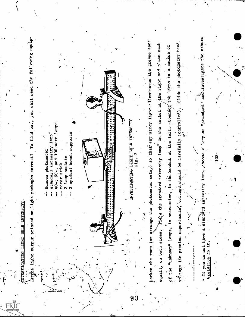
0
a
EVVESTIGATING LIGHT BULB INTENSITY:
4d'light butppt printed on light packages correct?
To find out, you will need the following equip-
memt!
- - Bunsen photometer
- - standard intensity,
lamp*
40-; 60-, and 100-watt lamps
meter stick
-- 2 lamp sockets
- - 2 optical bench supports
.'0
INVESTIGATING LIGHT BULB INTENSITY
Fig. 2
cparken the room.(or arrange the photometer setup) so that'anystray light illuminates-thegrease spot
equally on both sides.
ce the standardintensity
laMp* in the socket at,the right and.place each
of the "unknown" lamps, in succession
in the = socket at the left. -Connec
the laps to a. source of
voltage (in precise experimente;'voltageshould be carefully controlledi.
\
...
i-.,\_,--
%
4
* If you do not have a standard Intensity lamp,.choose a lamp. ,as
"standar- d" and investigate the others
:Slide the phqtogneter head.
1, relative to it.
7108-
4.
4410
o

f
along thepdtei stick until the condition of "balanced" illumination'
'is,obtained.
your notebook record 'all data in a chart such as
thelpne below; also show computations.
Calculate the intensity of the "unknown" with the formula,
Is x rx2
rs2
Table A
-USING
THE\-PHOTOMETER
Fig. 3
Lamp
.
being
0
tested
,
Is
(intensity
of
standard).
.rs
(distance
of standard
from
photometer
rx
(distance
of unknown
from
photometer)
.Ix
(intensity
of
unknown)
Number of
lumens printed
on package
.
Difference
40-watt
.....
60-watt
100 -watt
.1
lm
-lm
,'am
cm
cm
.
,,cm
?
cm
.
.
cm
-
....A cm
lm
\
lm
lm
lm'
lm
lm
,
..... lm
lm
lm
111/1
Iri\technic
pplications, so-called direct systems of illumination employ fixtures which send 90 percent
:of the light output directly downward to the, working area!,
So-called indirect systems -deflect from 90
to 100 percent of their light output upward, to be subsequently refleCted downward onto the work area
(usually reflected downward by the ceiling?which becomes a secondary source of Light). A so-called
-109-
1

;,
1
semi-direct system of illumination is
one in which 60 percent or more of the light is transmitted down-
*
ward,-and the remainder upward as in the indirect
system.
I
INVESTIGATING_J-TaHT DISTRIBUTIONS.
A graph of the intensity with which light,from
a
observations.
You will need:
system is distributed
- - Illumination meter
- - Polar coordinate graph paper
-- Protractor
can easily be made from direct
- - Large sheet of cardboards(about 3 ft x 3 ft)
'Draw a 15-inch radius circle on the cardboard; then draw a 12-inch radius
circle, using the same center.
After youhavemarked, increments of 10°
,
on the band farmed by the twocircle, cut out the inside of the 12-inch
circle.
Support the cardboard tlith VA) ringstands (see Figure 4).
The
light system to be-graphed should be placed at the center of the circles.
Readings
deewith the illumination meter at the different mere -.
"ments.
Readings shoull take place in a darkened room to avoid illumi-
nation -- from -other systems.
Your graph's should indicate where the maximum
intensity of the syst M is located.
You should also find some interest-
ping deigns en your graphs.
In your polar coordinate paper, plot\
intensity vs.- angler, and paste Orc.taPe the graphs into your notepOok.
INVESTIGATING LIGHT
DISTRIBUTION
'
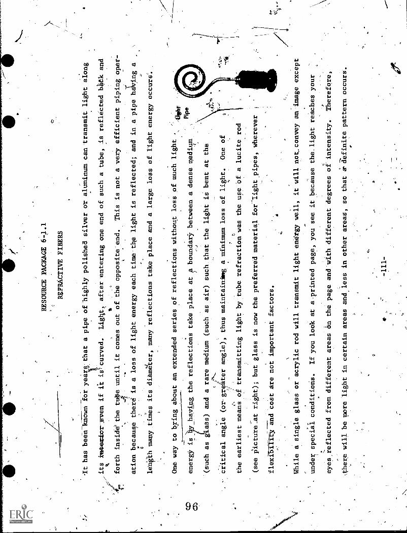
RESOURCE PACKAGE 6-1.1
REFRACTIVE FIBERS
It has been known for year
that a pipe of highly polished silver or aluminum can transmit light along
its kat-ea:tor:even if ft is curved.
Light,_ after entering one end of such a tube, is reflected b4ek and
forth inside' the tube until it comes out of the opposite end.
This is not a very efficient piping °per-
k
ation because there is a loss of light energy each time tile light is reflected; and in ,a pipe ha ing a
length many times its diameter, many reflections take place and a large loss of light energy occurs.
One way to bring about an extended series of reflections without loss of much light
.
energy isy having the reflections take place at ?. boundary between a dense medium
(such as
ass) and a rare medium (such as air) such that the light is bent at the
critical angle (or-greater angle), thus maintaining a minimum loss of light.
One of
the earliest means of transmitting light by tube refraction was the use of a lucite rod
(see picture_at right); but glass is now the preferred material for 'light pipes, wherever
flexibility and cost Are not important factors.
While a single glass or acrylic rod will transmit light energy well, it will not convey an image except
under, special conditions.
If you look at a-printed page, you see it because the light reaches your
eyes,reflected from different areas on the page and with different degrees of intensity.
Therefore,
,there will be more light in certain areas and less in other areas, so that a definite pattern occurs.
a
t
If the light waves from this same printed page were passed through a light pipewith a :ati-inch
eter, they would follow many different paths as they
traveled through the pipe.
Then, as tic rays
from all areas of the page left thp light tube, the image would normallybe so mixed as to
'nizable.
aO
If you decrease the size of the pipes (to something like. a coarse
threltsize) and
group the pipes into
.-
bundles, then the image will be divided into a number
of sma]l areas.
The image of each small area
will be conveyed by a'single fiber to a corresponding point at the other
end of'the bundle.
'.ow we
%ye
the advantage of flexibility, plus the advantage of being able to reproduce an image.
Sand an
arrangement is termed a fiberscope and
is.the basis of the science of fiber optics.
A fiberscope
enables a person to transmit an image around corners; for example, a surgeon can seeinside a person's
heart via the artery.
The idea of an optical pipe has been around for the last --ntury, but manydifficulties prevented its
f.
construction.
One of the, biggest drawbacks was that if simple'fibers were in contact; lightwould
leak from one fiber to another, causing a distortion of the image.' Also, the
surface of the fibers
would become scratched as they touched, causing a loss of light energyat the scratches.
0
problem was solved in the '50!s by creating a fiber
within a fiber, both transparent, The inner
fiberthas a high index of refraction, while the outer one has a low refractive index;
and total
-112-
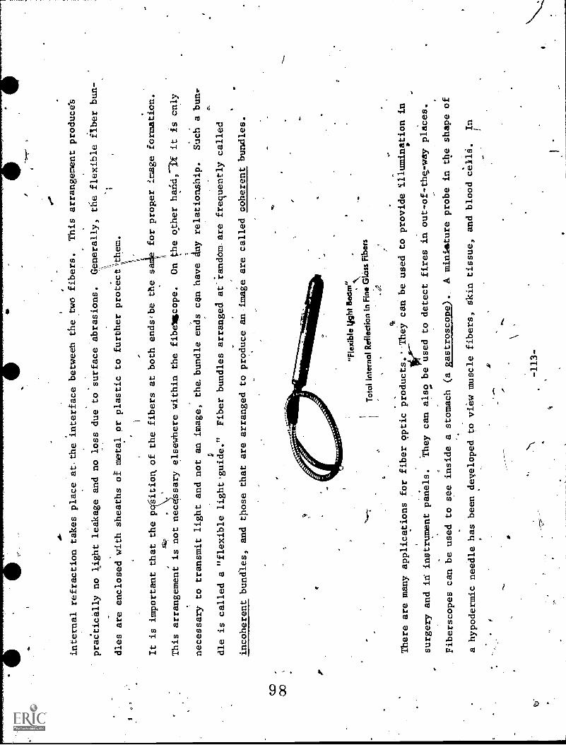
internal refraction takes place at. the interface between the two fibers.
This arrangement produces
praCtically no light leakage and no loss due to surface abrasions.
Generally, the flexible fiber bun-
dles are enclosed with sheaths of metal or plastic to further protectthem.
1
It is important that the p
ition, of the fibers at both ends,be the sa
for proper image formation.
rata
,This arrangement is not nec ssary elsewhere within the fibellicope.
On the other halid,--it it Is only
necessary to transmit light and not an image, the. bundle ends can have
Any relationship.
Such a bun:.
V
dle is called a "flexible light.guide."
Fiber bundles arranged at'iandom are frequently called
incoherent bundles, and those that are arranged to produce an image are called coherent bundles.
"Fle
xibl
e tig
ht B
eam
"
Tot
al In
tern
al R
efle
ctio
n in
Fin
e G
lass
Fib
ers
. 4.
There are many applications for fiber optic products.' They can be used to
provide illumination in
.10r.
surgery and in instrument panels.
They can also be used to detect fires in out-of-the,-way places.
Fiberscopes can be used to see inside a stomach (a
gastroscope).
A miniature probe in the shape of
a hypodermic needle has been developed to
view muscle fibers, skin tissue, and blood cells.
In

sag
Vs
industry, fiberscopes serve as instruments to inspect or-to control operations in hard-to-get-at places.
For example, fiberscopes.4re Used to examine turbine blades, boiler tubes, and various parts cf nuclear
reactors for flaws and cracks.
ofwalE.Irot
ft
,-114-
t
A t
INVESTIGATING FIBER LIGIsl:
You will need:
REWURCE*PACKAGE'6-l.2
FIBER LIGHT
several coherent and non-coherent fiber bundles of
same length and diameter
battery flashlight
high-intengity-lamp
transparent coloi wheel, mounted for hand rotation
ring stand and clamps
double convex lens
rubber bands
Join the light-receiving end of a number of non - coherent fiber bundles into a circle bymeans of a
. rubberband.
Then arrange the light-exiting end to form a pattern such as the letter, "L."
Point the
light-receiliing end towarda high-intensity lamp and check to see if an illuminated letter "L" becomes
visible at the opposite end.
In your notebook, sketch a diagram of the aptical arrangement.
Now, place a colOr wheel between the-source light
aftd the light-receiving.eld.
Rotate the wheel slowly
..,
,.
.
and describe-the images at the other'end.
Redord why it:was not necessary to employ coherent fiber
bundles for this.- Twist a mon-coherent fibef bundle into a wide U-shaped curve.: Hold one end Of the
14"U"
.-----,
close to your eye and direct a beam of light from a flashlight toward the otheretc11--Inyour note-
.
.,
.
4.
..
book, record your observations.
4
7
Use a high - intensity light to. illuminate aprinted page.
By means of a lens, focus the image of the
page on the face of a coherent
fiber.bundle twisted in the form of a semi-circle.
(Be sure to reduce
size of the image to a size small enough to cdver
the face.)
Examine the exit end carefully and
4
see if you can
dearly defined image.
Record whether or not the image is continuous or is
'composed of spots of light.
Make
etch of your image and of tha optical arrangement in
this inVes-
. tigation.
vis

RESOURCE PACKAGE 7-1.1
POLARIZED LIGHT I
Light is considered a transverse wave composed
of electric and magnetic fields oscillating at right
angles to each other and at right angles to their directionof travel (propagation).
Unpolarized light
consists of waves whose electric and magnetic planes are randomly oriented; whereas,
for polarized
light, these planes halve a fixed orientation 1n space.
Plane of Magnetic Field = B
Plane of Electric Field = E
ELECTROMAGNETIC WAVE
Fig. 1
Direction'of
this Wave
Figure 1 shows a polarized light wave
moving to the reader's right.
Thill.E and B
fields are up and down
(electric) and in and out (magnetic), respectively.
Because E and B fields always
oscillate in their
respective planes, this
wave6is polarized.
-117-
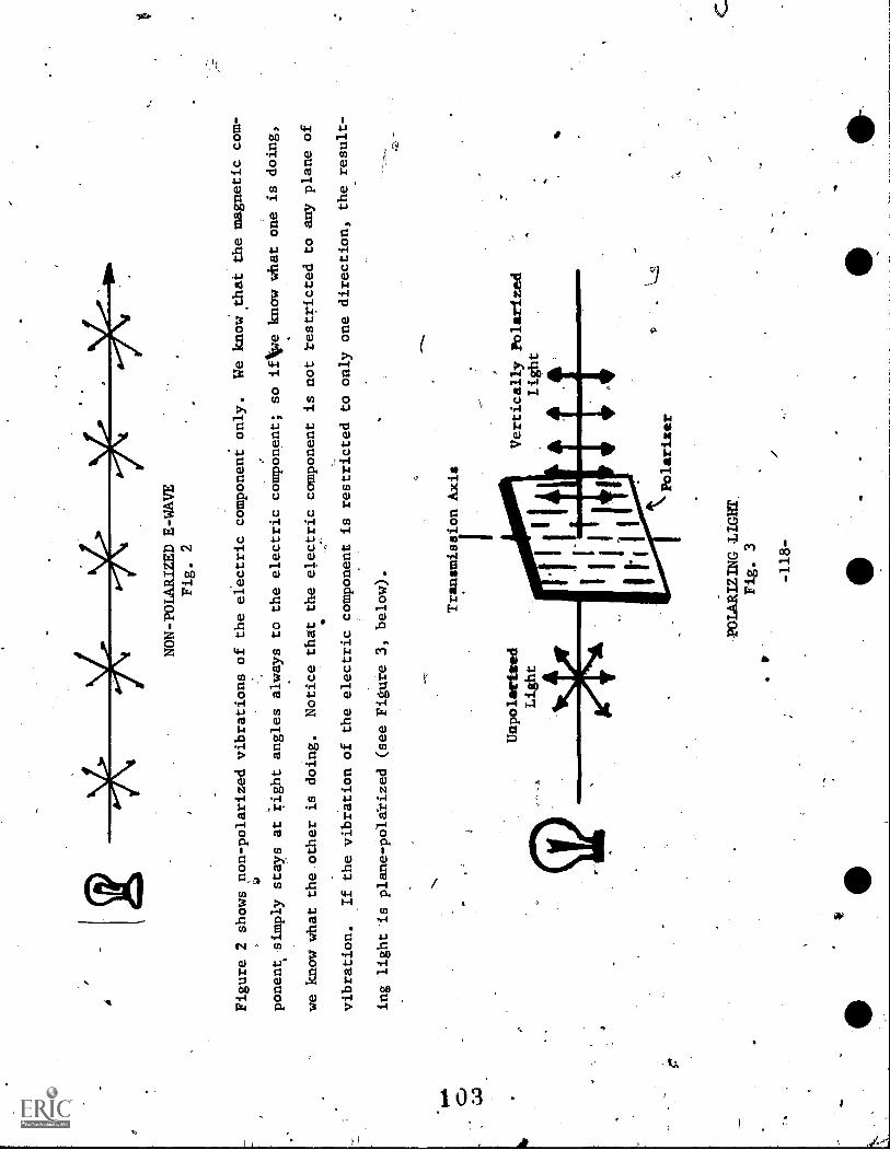
NON-POLARIZED E-WAVE
Fig. 2
Figure 2 shows non-polarized vibrations of the electric component only.
We know that the magnetic com-
si
ponentt simply stays at right angles always to the electric component; soifkie know what one is doing,
we know what the other is doing.
Notice that the electric component is not restricted to any plane of
vibration.
If the vibration of the electric component is restricted to only one direction, the
result-
_
ing light is plane - polarized (see Figure 3, below).
rt
Transmission Axis
Unpolartsed
Light
Vertically Polarited
Light
POLARIZING LIGET
Fig. 3
r
-118-
Polarixer
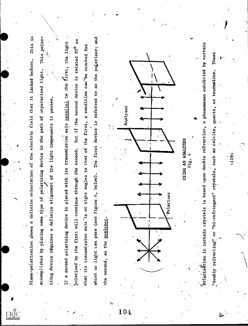
Plane-polarization shows a definite orientation of the electric field that it lacked before.
This is
accomplished by placing some type of polarizing device in the path of unpolarized light.
This ,polar-
dr
izing device requires a definite alignment of the light components it passes.
If a second polarizing device is placed with its transmission axis parallel to the first, the light
-
polarized by the first will continue through the second.
But if the second device is rotated 90° so
'that its transmission axis'is at right angles to that of the first, a condition can'be reached for
which no light can pass (see Figure 4, below).
The first device is referred to as the po4arizer; and
the second, as the analyzer.
Analyzer
Polarizer
USING AN ANALYZER
Fig. 4
POlarizAtion in certain crystals is based upon double refraction, a phenomenon exhibited by certain
"doubly refracting" or "bi-refringent" crystals, such as .calcite, quartz, or tourmaline.
These
qui
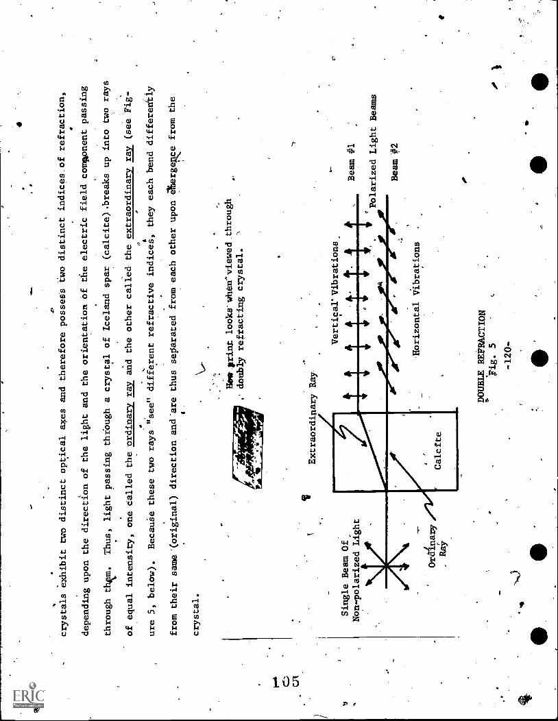
a.
Crystals exhibit two distinct optical axes and therefore possess two distinct indices.of refraction,
depending upon the direction of the light and the orientation of the electric field component passing
through thm.
Thus, light passing thrbugh a crystal of Iceland spar (calcite).breaks up into two rays
of equal intensity, one called the ordinary ray and the other called the extraordinary ray (see Fig -
0,
ure 5, below).
BecauSe these two rays "see" different refractive indices, they each benddifferently
from their same'(original) direction and'are thus separated from each other upon 4tergee from the
crystal.
Single Beam Of
Non-polarized Light
Ordinary
Ray
V
Hogs print looks'when^viewed through
doubly reftacting crystal.
'\
Extraordinary Ray
Calcite
Vertical' Vibrations
1I
:1'
1:
14Bolar:::: :light
Beams
Beam #2
Horizontal Vibrations
DOUBLE REFRACTION
'Fig. 5
.-120-
.
-

Each of the two beams of light are polarized, the ordinary beam consisting of
horizontal vibrations;
and the extraordinary beam, of vertical vibrations.
Something different happens in a crystal-of
tourmaline._ One of the polarized rays will be absorbed, and only one polarized ray
will emerge; and
in a nicol prise`, two crystals are joined together to cause one polarized ray to
be totally internally
reflected-(see Figure 6, below).
The most convenient and least expensive polarizing material is a
2.
__---sheet of polaroid.
This consists of an array of small polarizing crystals
embedded in glass, or in a
stretched plastic.sheet, so as to polarize in a given direction;
The tiny crystals increase the effi-
- -
ciency of the polarizes.
Unpolarized
Light
I
4P
Iceland Spar Crystal
Polarized
Light
Ordinary Rai/4"
Iceland. Spar Crystal
t-Black
Paint
(Absorber)
Canada Balsam
(cement)
CROSS SECTION OF A NICOL PRISM
Fig. 6
Light1nay also he polarized by reflection
In the case of light falling obliquely at an angle on la
.sheet, of glass, some of the light will be reflected and some will be 'transmitted.
Both the reflected
will
a,.
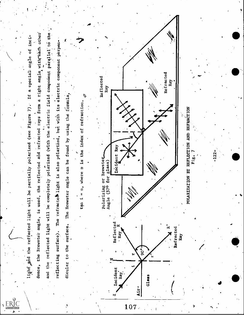
O
li§heAnd the reflected light will_be partially polarized (see Figure 7).
If a-speciaL angle of inci-
dence, the Brewster angle, is used, the reflected and refracted rays form a right angle withreach othei
and the reflected light will be completely polarized (with the electric field component parallelto the,'
reflecting surface).
The refracteAklight is also polariied, but with its electric component perpen--
dicular to the surface.
The Brewster angle can be found by using the formula,
Ray
R
r
tan i = n, where n is the index of refraction.
Polarizing or Brewste
Angle (57° for glass
Reflected
Ray
Refracted
Ray
a
POLARIZATION:BY REFLECTION AND REFLECTION
Fig: 7

111
One important application of polarized light is the deteCtion of strains in tranbpakent.materials.
Glass, celluloid,
or
BakeliteE7t6E-iialrdntrinatily
olarized Tight pas;ing through them.
How-
ever, when Subjected to
(such as. clear plastic)
polaroid will leave its
stress, they become;doubly refracting.
If a stressed, tr:
t material
is p,leted between twol -crossed polaroids,
field planes rotated as it passes
ent colors
rotateilhrough different :angles (by different
emerge through the 'second polaroid with certain colors
,
,7 as the basis
a
' *
for phOtStelastic analysis in the
a.
the 'light passing through
nle
first
As
he stressed material,witAiffer-
amounts).
The light will consequently
removed.
The resul ing stress patterns serve
study of engineering s
Sunglasses containing polarizing lenses maybe used'to control'glare
u,
and other nop7metallic.reflectors.
The light reflecte
from non- metallic
a1.
res.
from water surfacess road'surfaces,
surfaces is partially polar-
.
iied parallel to the reflecting surface (horizontally polarized).
The horizontally polarized,portion ,
is easily reduced4-Intlitsity
by the placemInt of vertically-oriented polaroid sunglasses.
The
unpolarized diffused (scattered) light passe
tlyough to the eye; being slightly modified by khe
.
sun -
Therefore, the useful part Of the
reflectefilight
is retsina (vision) and the objeCtionable
glasses.
'Tart
reduced (glass).
77
*
he
-1237
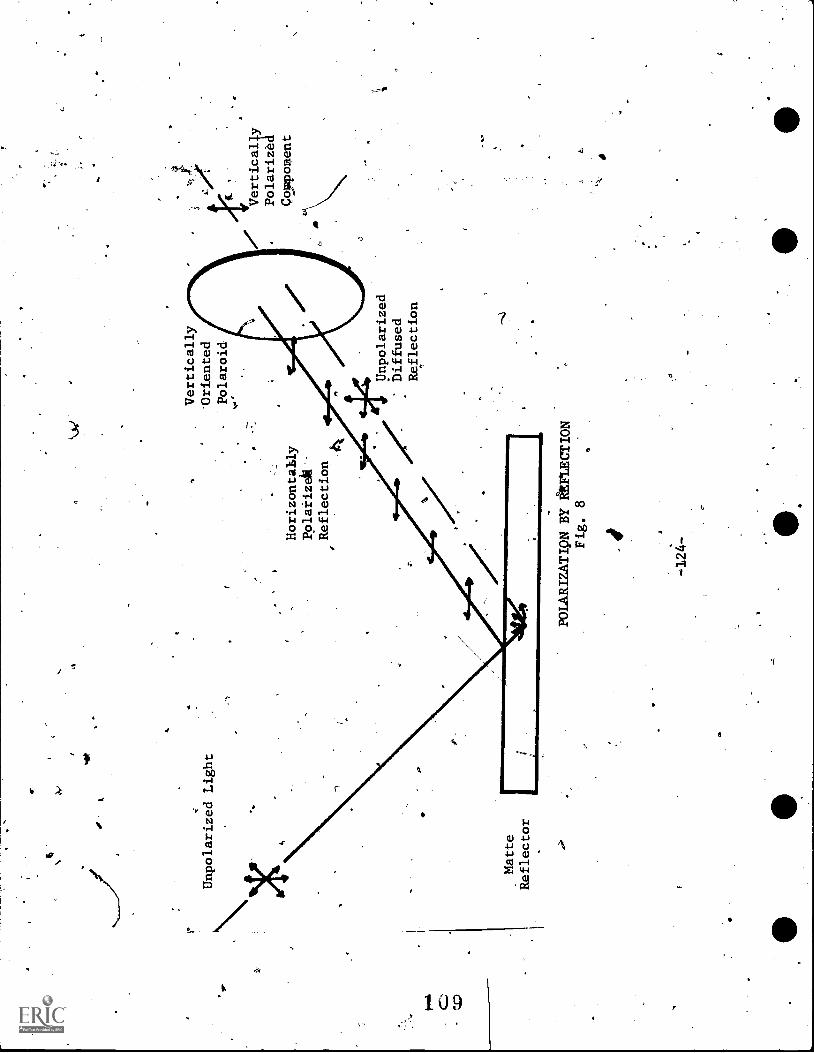
.st
Unpolarized Light
Vertically
'Oriented
-Polaroid
Horizontally
Pplarizelk-
Reflection
Vertically
Polarized
Couponent
Matte
Reflector
POLARIZATIQN BY REFECTION
Fig. 8
1'
-124-
Unpolarized
Diffused
Reflection

.
RESOURCE PACKAGE 7-1.2
POLARIZED LIGHT II
You will need:
- - Crystal of calcite
-- Pan of.polaroid film squares
- - Polaroid filters (discs)
- - Sheet of glass
-- Illuminator with stand and support
()
-
-- Cardboard screen with .3 -cm diametei hole covered with a pieceof
ing paper
- -Sheet of White cardboard
=- Large protractor
-7 V7shaped Bakelite piece
- -.4Clear plastic comb
An'impropAly annealed glass test tube
- shaped Bakelite member with a rivet hole near one corner
Arrange the illuminator and screen so thata.diffused circular source of light is made available.
Examine
.2
the light with each.polaroid film.
What structural change in the light waves is produced
by each polaroid held separately in front of pie light?
_ex
A4t
'-125-
fr

Place one filter over the other and examine the light passing through this combinatiok
(keep the
p-ola9id filters next to the light source).,
Keep one filter in a fixed position and slowly rotate the
-other filter.
Can you determine when transmission axes are parallel?
Perpendicular?
,4
Now place .a clear crystal of calcite over the print on this.page.
Can you account for the appearance
Of the print?
Examine what you see by rotating a single polaroid slowly ina plane parallel to that
of the page,-
Record a description of this in your notebook._
Go"to a wjndow and vieta car windows, cloUds, etc. while slowly rotating polarized materialssuch as
discs, sunglasses, etc.
ePlace a strip of glass on a table and vary the angle of incidence of the light fromthe illuminator
from about 40° to 70° (see diagram below): sLook through
a single polaroid filter at the image of the
Illuminator
Polaroid
I
,%VP Eye
light source refledted from the glass.
Rotate the filter so as to vary the brightness of the image
°
4
from maximum to minimum.
Does there appear to be a particfilar angle of incidence foi which both the
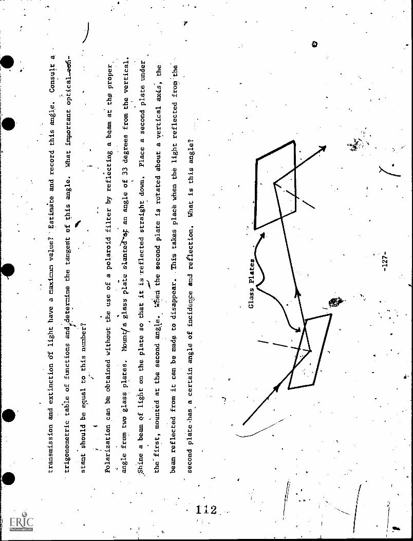
transmission and extinction Of light have a naximum value? -Estimate and
record this angle.
Consult
trigonometric table of functions andedetermine the tangedt of this angle.
What important optical-eofi-
)4kk
stant should be equal to this number?
Polarization can be obtained without the use of a polaroid filter
by reflecting a beam at the
proper,
angle from two glass plates.
Moul4a glass plate s/ante
an angle of 33 degrees from the vertical.
,Shine a beam of light on the plate so that it isareflected straight down.
Place a second plate under
the first, mounted at the secondangle. *en the second plate is rotated about a vertical axis, the
beam reflected from it can be made to disappear.
This takes place when the light reflected from the
second plate.has a certain angle of
incidertce and reflection.
What is this angle?
-127-
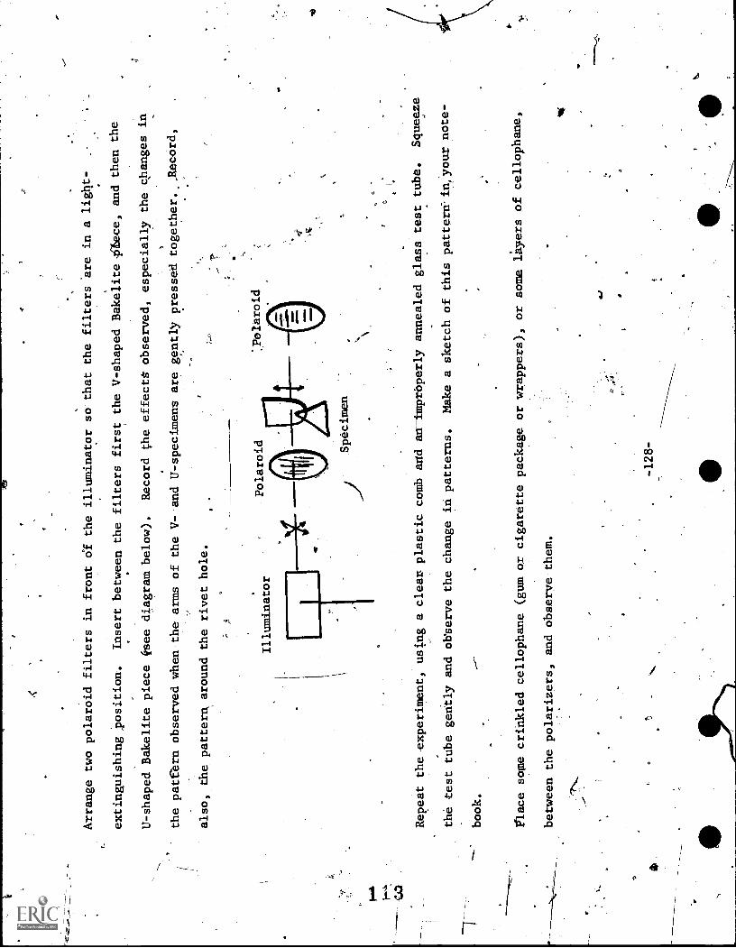
Arrange two polaroid filters in front of the illuminator so that
extinguishing ,position.
Insert between the filters first the V-s
U-shaped Bakelite piece (see diagram below).
the patfern observed when the arms of the V-
also, the pattern around the rivet hole.
;
Illuminator
the filters are in a light-
haped Bakelite iStece, and then the
Record the effects observed, especially the changes in
and U-specimens are gently pressed together._Jtecord,
*.Polaroid
Repeat the experiment, using a clear plastic comb acid an-i-mprOperly annealed glass test tube.
Squeeze
the test tube gently and observe the change in patterns.
Make a sketch of this patternA.n your note-
book.
fflace some crinkled cellophane (gum or cigarette package
between the polarizers, and observe them.
-128-
or wrappers), or some
lityers of cellophane,
4.1

RESOUHCE PACKAGE 8-1.1.
INTERFERENCE'
Interference occurs when two light waves' pass through the same
spacelat tie same time; we say that the
two waves are than superimposed.
The twowaves may reinforce each other (meet crest to crest, for
example), giving constructive tterference; .or-they may cancel each other (meet crest to trough, for
example), giving destructive interfdiencg.
In order to observe interference, one needs two coherent sources, two sources thatproduce light with-a
o
constant relationship; i.e., the waves from each source are in step (crest together and trough together)
1-*1
and are
the, same direction.
Until recently, it has been impossible to get two lndependent.light
sources which were-coherent.
The reason for this is that most sources emit light in short burst of
unpredicted duration, of many different wavelengths, and in various directions." However, if we want
interference of light, we can take light from one sourte,-spilt it, and have it travel -by two different-
paths to the same place, thus assuring coherency of "sources."
colors obsetved on a soap bubble, and on thin films of oil, are due to
interference of light.
Let us assume that we have monochromatic light
(light of just one color) incident on a thin film (the film May be oil, a
soap solution, or even air trapped betpeen two flat glass plates).
Some
4
of the light is reflected at the top of the film (ray 1 iNhe diagram);-
9-129 -,
-A.

CR
most of the light goes.th5ough the film, ands some is reflected. at the bottom surface of the film and
'comes'out again (ray 2 in,the diagram). A-Ifyou look down on the film, rays 1 and 2 will enter'the eye
and be focused on the retina.
Thus, coherent light is coming to the eye from two diffefent paths.
Ray 2 had to go back and forth through the film.
The two rays arriving at the
with each,other.
Ray 2 may be delayed (phase chanted
11 interfere
whole number of wavelengths (not frac-
tions of wavelengths) by this process.
*If so, it will arrive at Vie eye in phase (in "step" with)
ray 1, and the two rays will reinSorce each other (as in a "crest to crest" meeting).
An obserVer
looking at a film from such a position will observe a bright spot; on the other hand, ray 2 may be
-
.delayqd by some odd number of half wavelengths: 'fix, 4, -x, etc.
If so, it will arrive, 180° out of
22
se with ray 1, and the two rays will cancel each other.
An observer looking at the film from such
sdk-
a posit on will see a dark spot.
In general; 'such interference patterns consist of.bright fringes
alterna ing with dark fringes.
In 1801, ThoMlas Young performed a famous experiment which" suggested
1the interference of light.
Its essential features relate to the
interference phenomena just described.
Light from a small source F
illuminates
barrier which has two small narrow slits, S1 and S2,
very cloie'rtogether (see illustration at right).
The light which
gets thro gh these two slits falls on a screen.
Assuming that the light is monochromatic, we will see
a series
f bright lines alternating with-dark regions.
Assume that light spreads out from the source
-130-

/,-
F in we
wfronts.
The two slits are equidistant from the source,_ and each wave front reaches S1 and S2
/
at thp same time
Now, according toe<rgens' Principle, we Can-think of a portion of the wave front
at each slit act
g like an independent source of light, and each slit then producing its own wave
fronts..
These ar
represented as two sets of circles with S2 being the center at the top and Sl the
center at the bottom.
Since the light originally came from a single source F, the waves produced by
S1 and S2are coherent.
The waves overlap when they reach the screen and thus interfere with each
other.
In some places the waves arrive in phase and reinforce each other, giving a bright region or
line.
In other places, the waves arrive out of phase; -a darker region will appear where the waves are
out of phase.
One such bright place is B (see Figure 1, below), which is eqtiidistant from S1 and Si.
Ct
Scree*
Dar
k
Ligh
t
:cn
irsLo
irim
eniu
oifl
Ligh
t
INTERFERENCE
,Fig. 1
-131-

.
At this-place there will beta central maximum,
or a central bright line.
There are other places, on
either side of the central maximum, where
bright lines.-appear; that is, places where thetwo wave
fronts are in phase. At these locatiods,
one wave is a whole number of-wavelengths dut of hase with
:.
the other.(ahead or. behind).
The dark regions', between each light region,
are produced wh re the waves
are out of step by,multiples of
of a wavelength (any odd number of half wavelengths).
To calculate the distance between bright lines, consider the
diagram below.
The first bright line on
'the upper side of the central
maximum is represented by point P.. It is bright because thewave from
.r
._
Barrier
-132-
Screen
P (Ffrst bright line)
SIP
S 2P = X
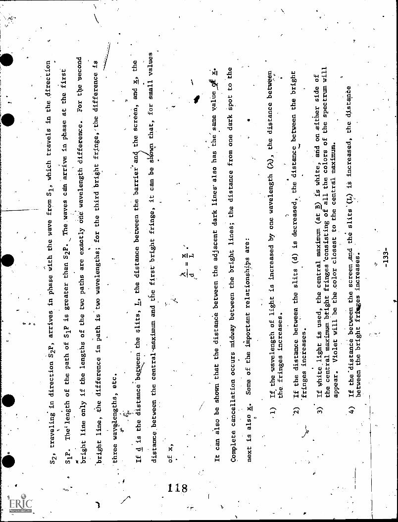
S2, traveling in
S1P.
The1 length
bright line only
bright line, the
direction S2P, arrives in phase with the wave
from S1, which travels in the direction
of the path of S1P is greater than S2P.
The, waves can arrive in phase at the first
if the lengths of the two paths are exactly onewavelength difference.
For the second
difference in path is two wavelengths; for the third
bright fringe, the difference is
three wavelengths, etc.
44-
If d is the distance between the slits, L, the distance
between the barrier an
the screen, and x, the
distance, between the central maximum and
the first bright fringe, it can be s own that, for small values
of x,
It can also be shown that the distance between
the adjacent dark lines also has the samevalue_ot x.
Complete cancellation occurs midway between the
bright lines; the distance from one dark spot to the
next is also x.
Some of the important relationships are:
-1)
If the wavelength of light is increased by onewavelength 00, the distance between
the fringes increases.
`2)
If the distance between the slits (d) is decreased,
the distance between the bright
-fringes increases.
3)
If white.light is used, the central maximum (at B) is
white, and on .either side of
the central maximum btight fringes'consisting
of all the colors of the spectrum will
appear.
Violet will be the color closest to the central maximum.
4)
If the'distance between the screen,and
the slits(L) is increased, the distance
between the bright fringes increases.
-133-
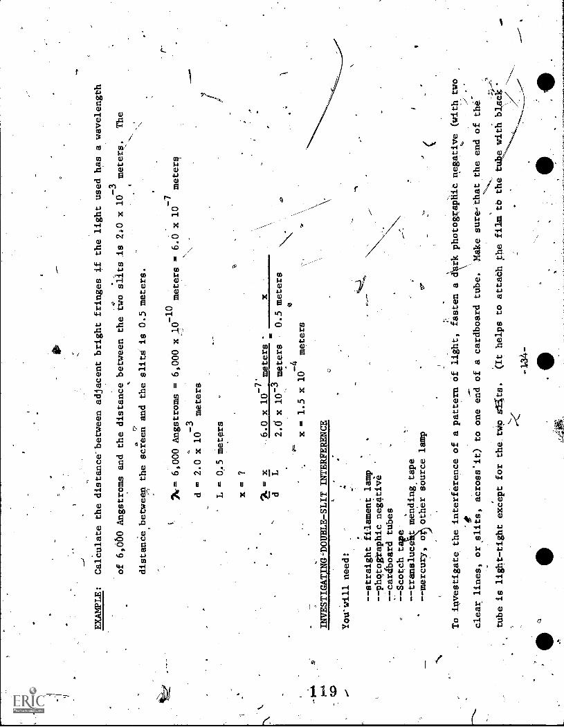
EXAMPLE:
Calculate the distance-between adjacent bright fringes if the light used has a wavelength
of 6,060 Angstroms and the distance
distance between the screen and the
-3
between the two slits is 2i0 x 10
meters.
The
slits is 0.5 meters.
26-= 6,000 Angstroms = 6,000 x
-3
d = 2.0 x 10
meters
L = 0..5 meters
x = ?
= x
d
6.0 x 10⁻⁷
meters '
-10
meters
x
-7
= 6.0 x 10
meters
2.6 x 10⁻³ meters
0.5 meters
x = 1.5 x 10⁻⁴meters
.
INVESTIGATING DOUBLE -SLIT INTERFERENCE
You'Will need:
--straight filament lamp
-- photographic negative
-- cardboard tubes
--Scotch t
--transluce
mending tape
--mercury, o
other source lamp
To .investigate the interference of a pattern
OIP
clear lines, or, slits, across'it) to one end of a cardboard
tube is light-tight except for the_tWp stets.
(It helps to
0 -134-
to'
of light, fasten a drk photog;apiiid negative (with two
r.
tube.
Make sure-that the end of the-
attach the film to the to e with black'
".$
Ale
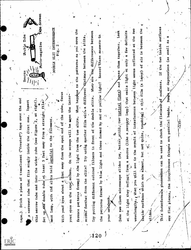
tape.). Stick a piece of translucent ("frosted") tape over the
end
401fa
narrower tube that fits snugly inside the first one.
Illsert
this narrow tube end into-the wider tube (see
Figure_2, at right).
4
Set u
e double tube at least 5 feet away
from a straight
film
r.
,ment lamp, with th6 sl is held parallel to
the
filament.
Iir
With your eyes about a
dot away from the open end of the tube, focus
your eyes on the tapelscreen.
On the screen will be 4,een the inter-
L'N
.D
ference patterns formed bythe light from the two slits.
Source
Dbub e Tube'
Photo-negative
'DOUBLE SLIT INTERFERENCE
Fig. 2
What hapkes to the patterns as you move the
screen farther from the slits?
Try using another filmwith4a different
stance between the slits.
Try putting different colored filters in front of
the double slits.
What:are
the patterns formed by blue, light and those formed by
red or yellow light?
Record-these answers,In
differences between
-----
_Tak
etwo clean microscope slides (or,
bettertil-1, ;two-optical flats) and
ess them together.
Look
at the light they reflect:froma source
(like a ,mercAry lamp) that
emi ts light at only a few definite
wavelengths., What you will see is the result of interferencebetween light waves reflected at the two
side-surfaces which are
lides.
This interferen4phehomenon can be used to check
thelflatries
are flat planes, the interference fringes are.
parallel bawls.
aImost, butnor quite, tophiggl a thin film
J-135-
(a layer) of air is between the
f surfaces.
If the two inside surfaces
or depressions (as small as a
f.
.IL
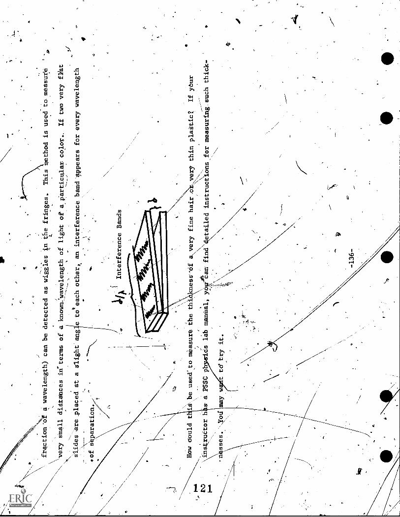
fraction'dt
a wavelength) can be detected as wiggles in the fringes.
This
thod is used to measure
.4
I0
V
every small didtahces in" terms ofa known:wavelength of light of a particular color, If two very fVat
slides are placed at a slight ang e toteach other, an interference bandappears for every wavelength
.
sof
paration.
141
Interference Bands
4,
-\
How dould t is be used' to measure the thi kness of
a, very fine hair .o , very thin plagtic?
If your
,\\
.A
_--
instructor h s a PSSC ph
*cs lab manual,
can fine4etailed instructions for measuring such thick-
P-A
----------
.n sses.
may w
t td try it
------',,,
_____,
o
C;,

\'\
,---;''
'N
know t at waVeg,,
nd aroun
obstacles.
-------.--.
---,,
--,
V:
speak, al
I
ough,
blocked
our view may
block
by..a crow of people-or by'a corueVof a_building.
If we
examine wa
waves, we can se
waves going around a small object; andafter as
t distance, the
___-,-1
look
lag"
ti as though_ the
had been rjgAin
g in
th eir wayJ
..'
RESOURCE PACKAGE 871.2
yr
DIFFRACTION
_
An example of waves bending occurs when
wellear%a person
t\D I
If 'light is
w,why do _oj cts'oast -sha
Why doesn't the light bend arouAd the object
and illuminate
ion behind it?
It can be s
wn that,the smaller thewavelength, the smaller_the
/9
ractian (ben
SinNthe
wav
elen
gth
Oi
light
ssmall colared to 'most objects,
ligl
7ght
ShgdOws
harp
and
-appears to travel in a st
line.
g)
cour
diffract
Niight _wave
.
to see
his bending.
n of 1j ht always occurs;
but becatt,r
-
chromatic light on an opaqu
14,
of
must look Very=catefully
shin - abeam of mono-
o
which has a narrow
rectangular opening cut into ie
s own in Figure
1).
4.,e
tthe light which
4o
t P
rrow slit, as
11 on a scre n held parallel to
e barri
rough the
7137
-
..11-
401;
141,
,
DIFFRACTION
Fig. 1
tit
*01
x fir
Cove, bend
r"..
4af
f
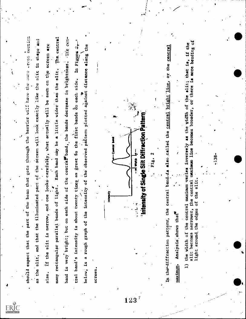
a.
should expect that the part of the beam that gets through the barrier will have the
sa-..?
ect
as the slit, and that the illuminated part of the screen will look exact- ly like the slit in shape and
size.
If the slit is narrow, and one looks,careful4y, what actually will be seen ©n thescreen are
4many rectangular parallel bands of light.
Each band tmy be a little wider than the slit.
The.central
band is very bright; but on each side of the centra ?band, the bands decrease in brightness.
cen-
%
tral band's intensity is about twenty times as great as the first bands on each side,
In Fil542.
below; is a rough graph of the intensity of the'observed pattern plotted against distance aletg\the
screen.
Inte
l Wit
Csa
irol
1.-,
\.In
tens
ity o
f Sin
gle
Slit
Diff
ract
!on
ttern
Fig, 2
In the-diffraction patt?rff, the central band.i.is also called the central bright line,or the central
maximum.
AnalYsia,shows that
1) the width of the central maximum varies inversely as the yidth of the slit; that
is, if the
slit becomes narrower, ghe central maximum line becomes broader, or there is
more bending of
light around, the edges of the slit.
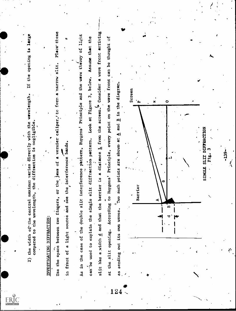
-
2) the width of*the central maximum varies directly with the wavelength.
If the opening is large
compared to the wavelength, the diffraction is negligible.
INVESTIGATING DIFFRACTION:
Use the space between two fingers, or thejaws of a vernier caliper,#to
form. a 'narrow slit.
Place these
re,
..
0
in front of a light source and see the interference bands.
ti
As in the case of the double slit interference phtiern, Huygens' Principleand the, wave theory of light
can-be used to explain the single slit diffraction pattern.
Look at Figure 3, below.
Assume that the
alit Was a,width d and that the, barrier is a distance L from thescreen.
Consider a wave front arriving-
at the slit opening.
According to Huygens' Principle, every point on the wave front canbe thought of
a
as sending out its own waves.
Two such points are shownat A and B in the diagram.
a/W
M=
0 ea
11.
d
Screen
SINGLE SLIT DIFFRACTION
Fig. 3
-139--
1

6Think of the waves A and B going toward P, a point on
.the screen.
If P is to be a dark spot on the
11
41
s
screen, the two waves traveling along' AP and BP must ounce/ each other.
Notice that the light.from.
CJ1
the two points A. and B travels different distances eo the screen.
Path BP is larger than path AP.
If
the difference ih the path length is one-half wavelength:the two waves will cancel each othei.
OPTIONAL:
It can be shown that for a dark point on the screen, sin B =
21.., where d is the distance of the slit,
X is 'the wavelength of the light source, and n = 1, 2,
3,...
.Whenn = 1, P gives us 'the point of
minimum intensity for the central line.
Thus, the distance MI is half of the width of the central band:
By looking at the relationship, sin 8 =
d'
it can be seen that as-the wavelength increases, sin 8
increases; and, therefore, the width of the central band must in;rease.
Aldo, if the width of the slit d
decreases, sin 8 increases; and, therefore, the width of the central band oust
increase.
INVESTIGATING DIFFRACTION PATTERNS OF SLITS AND OF HOLES:
Examine laser light diffracted by a narrow slit.
Then, try a circular hole instead of the slit.
Sketch
both diffraction patterns in your notebook.,
INVESTIGATING DIFFRACTION BY OPAQUE OBJECTS:
Look at the diffraction of light by an obstacle.
For example, use straight wires ofrdifferent sizes
(diameters) pgrallel to a laser light source.
Also, use a circular objact;such as a tiny sphere, the
-140n.
1

head of a pin, etc.
Also stretch a linen or cotton handkerchief or good quality and look through it,at
a distant light source, .4uch as a
street
light about a blobk away.
A piece of window screen will also
work, in place ok t11
handkerchief.
Describe these observations in your notebook.
A
Diffraction-patterns can be photograped.
You must have a dark room or a_large light-tight box.
Expose
a sheet of 3,000-ASA-speedPolaroid film for afew seconds.
As a light source, use the laser.
Rimor
blades, needles, or wire screens make good objects for photographing .v, Arrange
the equipment as shown
ti
below.
ego
-141-
V
O
4

7
RESOURCE PACKAGE 8-2.1
SELF-TEST
Work the following problems and answer the folldwing questions on another
sheet of paper.
1.
Two parallel slits, 0.5 mm apart, are illuminated by light whoselWavelength is 1.5 x 1077 meters.
A viewing screen is 2.0 meters away frond the slits.
What is the distance between two adjacent
bright lines?
2.
A double slit, with a spacing of 0.20 mm, is'illuminated with light whose
wavelength is 5,000,...,7
Angstrom waits.
An interference pattern'appears on a screen 2.5 meters away.
How far from the
ce;tral bright image is the next bright liner
3.
The continuous spectrum seen when looking at an oil film on street pavements is due to
(1) pigment
in the oil
(2) prism effect for the different-Wavelengths
(3) interference
(4) diffraction.
4.
In order to -observe interference of light, the two light sources used must
be (1) independent
(2) coherent
(3) dispersed
(4) polarized.
5.
Ann and John looked at the same white hot wire through a narrow
slit.
Ann's alit is narrower than
John's.
The distance between two adjacent red. lines as seen by Ann as compared
with that seen by
John is (1) greater
(2) the same
(3) smaller.
6.
The pattern when white light is seen through two adjacent isliits is evidence that light
(1) behaves
' like a wave
,(2) behavesiikg a stream of particles
(3)Pcan be polarized
(4).is electromagnetic
in nature.
Newton's ring's are proddced by (1) a pebble thrown obliquely into water
(2) a lighted cigarette
in pure oxygen
(3) diffraction
(4) interference.
8.
Two light waves traveling by different paths reach a point on the screen inphase.
One has an
amplitude a; the other has amplitude b.
The resulting amplitude is ay (a + b)
(2)
{a
b)
(3) %(a + b)
(4) %(a - b).

I
Kof
9.
An interference pattern has a black line.
This results from two waves getting tb the screen. at the
same time which are (1),in phase
(2) one-half wavelength "out of step
(3) one wavelength. out of
step
(4) two wavelengths out of step.
10.
In the,double slit experiment using monochromatic red light, if the distance between'the slits is
halved, the distance between two adjacent red lines in the, interference patterns is (1) halved
(2) dduble
(3) quadrupled.
11.
In the sing
slit diffraction pattern using monochromatic light (red), if the width of the slit is
doubled, the width-of the central maximum (1) decreases
(2) increases
(3) remains the same.
12.
If the distance between the slits and. the screen is doubled, the distance between the bright lines
-
in the interference patterns is (1) halved
(2) doubled
(3) quadrupled
(4) remains the same.
(
0
-144-

N CO
-r
,
RESOURCE PACKAGE 8-
SELF-TEST ANSWERS
1.
2.
6 x 10⁻⁴
meters
.1-
6.25 x 10⁻³ meters
3.
(3)
4.
(2)
5.
(1)
6.(
7.
(4)
8.
(I)
9.
(2)
10.
(2)
11.
-(2)
12.
(2,
rA
lt
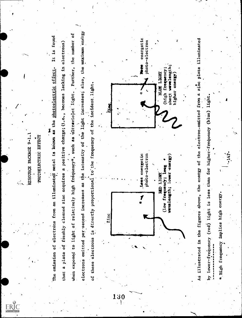
RESOURCE PACKAGE 9-1.1.
-PHOTOELECTRIC EFFECT '
116
The emission of electrons from an illuminated metal is known as the photoelectric effect.
It is found
that a plate of freshly cleaned zinc acquires a positive charge;(i.e.., becomes lacking inelectrons)
when exposed to light of relatively high friquenoy*, such as ultraviolet light.
Further, the number of
electrons emitted per - second increases as the intensity of the light increases; also, the maximum energy
of these electrons is directly proportional to.the frequency of the incident, light.
Zinc
Less energetic
photo-electron
4
141) LIGYT
.
(low frequenc; it:mg
4
wavelength; lower-energy)
Mire
energetic
photo-electron
BLUE LIGHT
(high frequency;.-
short wavelength;'
higher energy)
As illustrated in the figures above, the energy of the electron,emitted from a zinc plate illuminated
by lower-frequency (red) light is less than for higher-frequency (blue) light.
* High frequency implies high energy.
A
-147-

11,
Many attempts were made to explain this effect; butit was Einstein, in 1905, who used the quantum or
photon theory of radiation to explain what was happening.
Einstein's equation for the Photoelectric
effect is:.
= ICY - Co..)
where the terms on tht left-hand side represent the maximum kinetic energy attained by an emitted elect.
tron and wbere'the right-hand symbols are:
h is. Plank's constant,(6.6 x 10⁻³⁴ joule-sec); yis the
o.
frequency.of the incident light; and (A) is the work-function or the energy required to liberate the
electrons from the,surface of the illuminated material.
Strongiytelectropositive metals, such as lithium, sodium, potassium, or cesium emit an easily measurable
supply of electrons when exposed to ultraviolet light and respond, to a.lesser extent, to visible light
<-,as well.
The polished zinc platp discussed earlier` responds only to ultraviolet light, and would become
insensitive if the source of ultraviolet were blocked bya'sheet-of ordinate glass (which absorbs this
ultrav olet light).
Platinum, on the other hand, is comparatively ins
e to light.
It.should be noted that if the incident light is below a certain frequency, no electrons can be emitted
from:any metal, ..regardless of the intensty of the light incideut,upon its surface.
This frequency
boundary is 'known as the photoelectric threshold,,and it is different for different metak.d.
-148
=
INVESTIGATION OF PHOTOELECTRIC EFFECT:
You will need the following:
high-pressure mercury arc lamp ctith quartzwindow and an associated power supply serving
at a choke 4 inductive ballast fgr the lamp
Braun electroscope with damp-proof
insulation
wooden blocks for height adjustment
C
freshly sandpapered zinc plate
sheet'of polished aluminum
square of plexiglasS
ti)
sheet of ordinary glass
glass rod and crinkly wrapping
tissue
(:ilectrification)
polystyrene rod and wool (- electrification)
stop watch (1/5 sec)
sandpaper
protective goggles
BE SURE TO SHIELD YOUR EYES FROM DIRECT EXPOSURE TO
ULTRAVIOLET.
(ULTRAVIOLET LIGHT
CAN CAUSEIINDNESS EVEN THPUGH'IT IS
INVISIBLE-)
Cut and bend small corners.in the zinc plate so thatit may be balanced vertically on the knob of a
Braun electroscope (see Figure 1-on page 150).
Connect the mercury arc lamp, with the quartz window
4

my.
temporarily directed away from the zinc, plate.
Remove all surface film (zinc oxide).from the plate by
,ftubbing with sandpaper, andthen place it in position on the electroscope.
Charge the electroscopeby
adirecting the ultraviolet output directly upon ahe
to the leaves of
electroscope.
fl
Ultraviolet Radiation
MercuicLamp
zinc plate.
In your notebook,cdescribe what happens
Balanced Zinc Plate
Braun Electroscope
-PHOTOELECTRIC EFFECT
Fig. 1
Discharge the elettroscope and repeat the above, with the zinc plate charged negatively.
(Your instructor
can tell you how to do this.)
Measure the time required for the full discharge of the electroscope.;
-150-
5
Record this time. Now, discharge the electroscope and repeat the procedure, with the zinc plate charged'
Apositively.
Try the same procedure with the aluminum plate, charging tie electroscope first negatively
and then positively.
Recordyour observations and desCribe any differences in the effects that you
observed between the two metals, the zinc
aluminum.
Again, charge the zinc plate negatively and. repeat the procedure, but first place a sheet of plexiglass
in the path of the ultraviolet beam. .Next, repeat the procedure using a sheet of glass instead of.plexi-
.
glass.
Describe the results in your notebook.
tom
iBy increasing the distance between the zinc plate.a
Ie mercury aic lamp, see if you'can show that-
C 4;6
the number ofr electrons emitted per second is proportional to the intensity of the incident'light.
A'
factor of 2 inctease in distance (doubling the distance) will result in a decrease in tffe intensity
level by a factof,of 4.
(2?
a
0
What would you
edict as to .the number of electrdhs released per second at
4
the different distances?' To check your prediction, use a stop watch and record the time of complete,dis-
charge for different distances.
Then make a graph, in your-notebdok oftimer. distance.
QUESTIONS
In which industries is the photoelectric effect Ised?
Which metals might be in greatest demand in these
0
industries?
What effect might the energy crisis have on further scientific studies of the photoelectric
effect?
Write a simple response to these inyour notebook; your nstructor can furnish suitable refer-
,
ences for you.
\
-151-