Embed Size (px)
Citation preview

DOCUMENT RESUME
ED 391 908 CE 070 766
TITLE Blueprint Reading for Welders. Training Guide.INSTITUTION Philippine Congress, Manila. Congressional Oversight
Committee on Education.PUB DATE 95NOTE 102p.; For related documents, see CE 070 /58, CE 070
760, CE 070 763, and CE 070 765-768.PUB TYPE Guides Classroom Use Teaching Guides (For
Teacher) (052)
EDRS PRICE MF01/PC05 Plus Postage.DESCRIPTORS Adult Education; *Adult Vocational Education;
Behavioral Objectives; *Blueprints; *Competency BasedEducation; *Engineering Drawing; Learning Activities;*Orthographic Projection; *Welding
ABSTRACTThis training g.ide, developed during a project to
retrain defense industry workers at risk of job loss or dislocationbecause of conversion of the defense industry, is designed for acourse in blueprint reading for welders. The following are among thetopics covered in the course: information on a blueprint;orthographic projection; views in orthographic drawings; representingan object; sketching an isometric drawing; surface identification;basic lines and their identification; local and general notes; titleblocks; dimensions; dilension units; rules for dimensioning;tolerance dimensions; welding symbols; reference lines; basic weldsymbols; types of welds; supplementary symbols; welding symbol andelements; fillet welds and finishes; and groove, plug, slot, spot,seam, and flange welds. IAcluded in the guide are the following:course outline; transparency masters; student handouts; quiz; studentexercises; and reference tables. (MN)
***********************************************************************
Reproductions supplied by EDRS are the best that can be madefrom the original document.
***********************************************************************

ILep "ntRead'g
foelders
TrainingOil of Educannai Roseanin ann
U S DEPARTMENT OF EDUCATION_ Guide "PERMISSION TO REPRODUCE THISED14CATIONAL RESOURCES INFORMATION MATERIAL HAS BEEN GRANTED BYCENTER (ERIC)
This document has been reproduced asreceived from the poison cr organqationOriginating it
0 Minor changes have been made toimpiove reproduction quality
Points of view or opinions stated in thisclocum, do not noroccarily ioprnconl011(h-110ER! po,Ivon of policy
2
J 5--thepsdTO THE EDUCATIONAL RESOURCESINFORMATION CENTER (ERIC)
BEST COPY AVAILABLE

Tao
le o
f C
onte
nts
Page
1
Info
rmat
ion
on a
Blu
epri
nt2
Tea
m Q
uiz
2
Ort
hogr
aphi
c Pr
ojec
tion
3
Vie
ws
in O
rtho
grap
hic
Dra
win
gs4
Rep
rese
ntin
g an
Obj
ect
5
Sket
chin
g an
Iso
met
ric
Dra
win
g6
Surf
ace
Iden
tific
atio
n7
Bas
ic L
ines
8-
10
You
r N
otes
11
Iden
tifyi
ng B
asic
Lin
es12
-13
Loc
al a
nd G
ener
al N
otes
14
Titl
e B
lock
s15
Dim
ensi
ons
16
Dim
ensi
on U
nits
17-1
9
Rul
es f
or D
imen
sion
ing
20
Dim
ensi
onin
g Pr
actic
e21
Tol
eran
ce D
imen
sion
s22
Wel
ding
Sym
bol
23
Ref
eren
ce L
ines
24
Bas
ic W
eld
Sym
bols
25
Typ
es o
f W
elds
26
Supp
lem
enta
ry S
ymbo
ls27
Wel
ding
Sym
bol &
Ele
men
ts28
You
r N
otes
29
Fille
t Wel
ds &
Fin
ishe
s30
-33
Gro
ove
Wel
ds34
-38
Plug
Wel
ds39
-40
Slot
Wel
ds41
-42
Spot
Wel
ds43
-45
You
r N
otes
46
Seam
Wel
ds47
-48
Flan
ge W
elds
49-5
0
Cla
ssif
icat
ion
of C
hara
cter
istic
s51
4

Itif
orm
atio
n-:..
oti.a
Bhi
epri
ntIn
form
atio
n fo
und
on a
blue
prin
t:P
arts
to b
e m
anuf
actu
red
Dim
ensi
ons
Not
es
Mat
eria
l
Titl
e of
the
draw
ing
and
part
Dra
win
g nu
mbe
r
Man
ufac
ture
s na
me
Tol
eran
ces
Sca
le o
f the
dra
win
g
Nam
es o
f the
dra
fter,
engi
neer
, and
chec
kers
Dra
win
g an
d ap
prov
alda
tes
Rev
isio
n in
form
atio
n
Tea
m Q
uiz:
Loo
k at
the
prov
ided
pri
nts
In y
our
fold
er.
Loc
ate
the
requ
este
d In
form
atio
nbe
low
.W
ith y
our
part
ner,
num
ber
the
vari
ous
part
s of
a p
rint
.
1.Lo
cate
the
part
s, a
s sh
own
in li
ne
draw
ings
.
2.P
oint
out
the
dim
ensi
ons.
3.P
oint
out
the
note
s.
4.W
here
is th
e m
ater
ial l
iste
d?
5.W
hat's
the
title
of t
he d
raw
ing
and
the
draw
ing
num
ber?
6.W
here
is th
e O
nan/
Cum
min
s na
me
loca
ted
on th
e pr
int?
7.P
oint
out
the
tole
ranc
es.
8.W
hat i
s th
e sc
ale
of th
is d
raw
ing?
9.W
ho d
rafte
d th
is p
rint?
10.
Who
app
rove
d th
e pr
int?
11.
Whe
n w
as th
e pr
int d
rafte
d?
12.
Poi
nt o
ut th
e re
visi
on in
form
atio
n.
2

Ort
hogr
aphi
c pr
ojec
tion
is a
cpic
sellu
ngth
etr
ue s
hape
of
an o
bjec
t on
a
sing
le p
lane
.
Eve
ry li
ne o
f an
obj
ecti
s
on a
sin
gle
plan
e.
Eve
ry li
ne o
f the
obj
ect
mus
t app
ear
as a
line
or
poin
t on
the
plan
eof
proj
ectio
n.
Lin
es th
at c
an b
e se
enar
e sh
own
asso
lid li
nes.
Lin
es th
at a
re n
otvi
sibl
e, b
ecau
se th
ey a
rehi
dden
by
som
e pa
rt o
fth
e ob
ject
, are
repr
esen
ted
byda
shed
lines
.
Ort
hogr
aphi
c pr
ojec
tion
isdi
vide
d in
to 6
vie
ws:
Fron
t Vie
w:
Top
Vie
w:
Rig
ht s
ide:
Lef
t sid
e:
Bot
tom
vie
w:
Bac
k vi
ew:
mai
n vi
ew o
f th
e pa
rt th
atsh
ows
mos
t det
ail.
proj
ectio
n up
war
dfr
om f
ront
view
.
view
to th
e ri
ght o
f th
e fr
ont.
view
to th
e le
ft o
f th
e fr
ont.
oppo
site
the
top
view
.
oppo
site
the
fron
t vie
w.
Prin
cipl
ePr
ojec
tions
:T
he p
rinc
iple
pro
ject
ions
are
calle
d fr
ont,
top
and
side
vie
ws.
The
pro
cess
of
proj
ectin
gth
e es
sent
ial v
iew
s in
to a
sin
gle
plan
e is
kno
wn
as o
rtho
grap
hic
proj
ectio
n.
TO
P
FR
ON
TR
IGH
T S
IDE
38

7S7:
1e,8
7vs
'.
.h..
Srth
ogra
phiç
Dt.4
* n
s,
PIC
TO
RIA
LR
EP
RE
SE
NT
AT
ION
BA
CK
9
LEF
T S
IDE
BA
CK
1
I
TO
P
4
I
BO
TT
OM
RIG
HT
SID
E
)
BA
CK 10

OB
LIQ
UE
ISO
ME
TR
IC
FR
ON
T
(a)
PIC
TO
RIA
L
RIG
HT
SID
E
TO
P
FR
ON
TR
IGH
T S
IDE
(13)
OR
TH
OG
RA
PH
IC P
RO
JEC
TIO
N (
IN T
HR
EE
VIE
WS
)
Obl
ique
: To
deve
lop
an o
bliq
uedr
awin
g, a
n or
thog
raph
ic v
iew
of
the
obje
ct is
fir
st d
raw
n w
hich
bes
tde
scri
bes
the
shap
e an
d sh
ows
the
mos
t det
ail o
f th
e ob
ject
.
Aft
er th
e or
thog
raph
ic v
iew
isco
mpl
eted
, one
sho
uld
draw
par
alle
lre
cedi
ng li
nes
abou
t 45
degr
ee a
ngle
sfr
om th
e co
rner
s of
the
view
(ei
ther
toth
e ri
ght o
r to
the
left
) to
dev
elop
the
thre
e-di
men
sion
al e
ffec
t. T
he e
xten
tof
the
rece
ding
line
s is
abo
ut o
ne-h
alf
the
leng
th th
at w
ould
be
show
n fo
r an
orth
ogra
phic
dra
win
g.
Isom
etri
c: T
o de
velo
pan
isom
etri
c sk
etch
, iso
met
ric
grap
hpa
per
is p
refe
rabl
e. A
nis
omet
ric
sket
ch h
as a
ll of
its
surf
aces
sho
wn
at30
deg
ree
angl
es. I
n th
e in
itial
prep
arat
ion
of th
e sk
etch
, a v
iew
of
the
obje
ct th
at b
est s
hoes
its
shap
ean
d de
tail
is s
elec
ted
and
sket
ched
at
30 d
egre
es.
Aft
er c
ompl
etio
n of
the
basi
c vi
ew,
para
llel r
eced
ing
l;lin
es a
re s
ketc
hed
at 3
0 de
gree
ang
les
from
eac
h of
the
corn
ers.
Onl
y th
ose
lines
that
repr
esen
t the
vis
ible
par
t of
the
obje
ctar
e sh
own.
The
ske
tch
is c
ompl
eted
by d
raw
ing
the
back
edg
es.
115

Prel
imin
ary
view
for
sket
chin
gis
omet
ric
Lef
tand
righ
t iso
met
ric
sket
ches
of
a
draw
ing
of a
fabr
icat
ed T
-sup
port
.fa
bric
ated
T-s
uppo
rt.
6
BE
ST
CO
PY
AV
AIL
AB
LE1
3
ON
O.'"
:
!:,1
;;r1,
......
,
1 4

15
Ent
er th
e le
tters
from
the
pict
oria
lvi
ew in
to th
e co
rres
pond
ing
ballo
ons
on th
e
orth
ogra
phic
vie
ws.
0 0
7
1C

'44,
01
The
re a
re s
ever
al d
iffe
rent
type
sof
line
s us
ed o
n a
prin
t.
Eac
h lin
e ha
s a
diff
eren
tm
eani
ng.
Th
-. p
urpo
se o
f ea
ch li
nede
als
with
:
1.Sh
ape
of a
n ob
ject
2.D
imen
sion
ing
of a
n ob
ject
Typ
e of
Lin
eO
BJE
CT
LIN
E
HID
DE
N
LIN
E
Des
crip
tion
Purp
ose
Thi
ck s
olid
line
.T
o sh
ow th
e vi
sibl
e sh
ape
of a
part
.
Bro
ken
line
of m
ediu
mT
o sh
ow e
dges
and
out
lines
not
thic
knes
s.vi
sibl
e to
the
eye.
CE
NT
ER
LIN
E
Fin
e, b
roke
n lin
e m
ade
up o
f aT
o sh
ow th
e ce
nter
of c
ircle
s,
serie
s of
sho
rt a
nd lo
ngar
cs a
nd s
ymm
etric
alob
ject
s
dash
es a
ltern
atel
y sp
aced
.an
d to
aid
in d
imen
sion
ing
thes
epa
rts.
EX
TE
NS
ION
EX
TE
NS
ION
LIN
ELI
NE
DIM
EN
SIO
N L
INE
Ext
ensi
on li
nes:
fine
line
s th
atE
xten
sion
line
s: s
how
)
exte
nt fr
om th
e ob
ject
with
adi
men
sion
ing
poin
ts.
light
bre
ak b
etw
een.
Dim
ensi
on li
nes:
touc
h th
e
Dim
ensi
on li
nes:
fine
line
sex
tens
ion
lines
and
sho
w
with
arr
owhe
ads,
unb
roke
ndi
stan
ce g
iven
by
the
exce
pt w
here
the
dim
ensi
on is
dim
ensi
ons.
i 78
IS

Tyt
ie o
f L
ine
Des
crip
tion
LEA
DE
R
Fin
e, s
trai
ght l
ine
with
an
arro
whe
ad o
r ro
und
solid
dot
at o
ne e
nd. I
t is
usua
lly d
raw
nat
an
angl
e.
Poi
nts
dire
ctly
to s
urfa
ce fo
r th
epu
rpos
e of
dim
ensi
onin
g or
addi
ng a
not
e. A
dot
may
be
used
at t
he e
nd o
f the
str
aigh
tlin
e w
here
ref
eren
ce is
mad
e a
surf
ace
area
.
PR
EF
ER
RE
DA
ALT
ER
NA
TE
B.
CU
TT
ING
MIS
PLA
NE
LIN
E
j
A h
eavy
, bro
ken
line
mad
e up
of a
ser
ies
of s
hort
das
hes
Aal
tern
atel
y sp
aced
(or
sol
idhe
avy
lines
or
long
das
hes)
.A
rrow
head
s ar
e pl
aced
at
right
ang
les
to th
e cu
tting
plan
e lin
es.
Indi
cate
whe
re a
n im
agin
ary
cut
is m
ade
thro
ugh
the
obje
ct. T
hear
row
poi
nts
in th
e di
rect
ion
inw
hich
the
sect
ion
shou
ld b
evi
ewed
. Let
ters
nex
t to
the
arro
whe
ads
iden
tify
the
sect
ion
in c
hase
s w
here
mor
e th
an o
nese
ctio
n is
sho
wn
on th
e dr
awin
g.
ST
EE
L
ZIN
C, L
EA
D,
WH
ITE
ME
TA
L,B
AB
BIT
T,
AN
D A
LLO
YS
SE
CT
ION
LIN
ES
/ //
//
//
/C
AS
T IR
ON
,
/M
ALL
EA
BLE
IRO
N,
CO
PP
ER
,B
RA
SS
,B
RO
NZ
E,
AN
DC
OM
PO
SIT
ION
S
GE
NE
RA
L U
SE
FO
RA
LL M
AT
ER
IALS
//f MA
GN
ES
IUM
,A
LUM
INU
M,
AN
D IT
SA
LLO
YS
Ser
ies
of fi
ne li
nes
solid
or
solid
and
bro
ken
arra
nged
insp
ecifi
c pa
ttern
s. T
hey
may
be s
how
n ei
ther
str
aigh
t or
curv
ed. W
hen
show
n st
raig
ht,
they
are
usu
ally
dra
wn
at 4
5de
gree
ang
le.
Indi
cate
the
imag
inar
y cu
tsu
rfac
e re
ferr
ed to
by
the
cutti
ngpl
an li
ne. T
o re
pres
ent v
ario
uski
nds
of m
ater
ials
.
1 9
92
0

CH
AIN
LIN
EH
eavy
, bro
ken
line
mad
e up
of
Indi
cate
s th
e lo
catio
n an
d ex
tent
a se
ries
of lo
ngan
d sh
ort
of a
sur
face
are
a.da
shes
alte
rnat
ely
spac
ed.
SHORT
Hea
vy, i
rreg
ular
line
dra
wn
BREAK LINE
free
hand
.
To
show
a s
hort
bre
ak. T
oco
nser
ve s
pace
on
adr
awin
g.T
o sh
ow a
par
tial s
ectio
n.
Rul
ed, l
ight
line
with
free
hand
To
show
a lo
ng b
reak
. To
LONG
BREAK LI
zigz
ags.
cons
erve
spa
ce o
n a
drawinIg.
111
NE
PHANTOM
LINE
Ligh
t, br
oken
line
mad
e up
of
a se
ries
of o
ne lo
ngan
d tw
osh
ot d
ashe
s.
To
show
alte
rnat
e po
sitio
ns o
f apa
rt. T
o sh
ow r
elat
ions
hip
ofex
istin
g pa
rt to
new
par
t. T
osh
ow m
achi
ned
surf
aces
.
10


25

Ref
er to
the
draw
ing
abov
e to
iden
tify
the
type
san
d lin
esan
d th
eir
func
tions
.
Iden
tify
tofo
llow
ing
type
sof
line
s:G
iven
the
func
tion
orfu
nctio
ns o
f
Ath
e fo
llow
ing
lines
:
A Bon
usQ
uest
ion:
1
Wha
t doe
sQ
hav
ere
fere
nce
to?
1 3
2 L
;

Loca
lG
ener
a N
otes
A n
ote
is le
ttere
din
form
atio
n co
ncer
ning
the
deta
ils o
fcon
stru
ctio
n. T
he n
ote
expl
ains
, spe
cifi
es, o
rre
fers
to th
e m
ater
ial a
nd/o
r pr
oces
ses
need
ed to
mak
e th
e
part
.Not
es h
elp
to c
onse
rve
spac
e on
the
prin
t, an
d to
sav
etim
e in
pre
pari
ng th
e
draw
ing.
It i
sof
ten
show
n as
an
abbr
evia
tion
or s
ymbo
l.
Loc
al N
otes
:W
hen
a no
teap
plie
s to
a p
artic
ular
part
on
anob
ject
, it i
sca
lled
a lo
cal n
ote.
Suc
h
a no
te is
pla
ced
near
cine
of t
he
view
3 re
pres
entin
gth
e pa
rt.
Thi
s su
rfac
e m
ust
be f
lush
and
have
now
eld
spat
ter.
29
Gen
eral
Not
es:
A g
ener
alno
te a
pplie
s to
the
draw
ing
as a
who
le. I
t is
plac
edin
an
open
spac
o aw
ayfr
om th
e vi
ews
soth
at it
can
be
seen
eas
ily.
Exa
mpl
e:A
ll w
elds
mad
eus
ing
GT
AW
.
14

Titl
e bl
ocks
con
sist
of:
A.
Nam
e of
par
t or
proj
ect
B.
Qua
ntity
req
uire
dC
.M
ater
ial d
escr
iptio
nD
.S
cale
siz
e us
edE
.D
raw
n by
F.
Che
cked
by
G.
Dra
win
g N
umbe
rH
.D
ates
I.T
oler
ance
sJ.
Ona
n/C
umm
ins
nam
eK
.D
raw
ing
Pro
ject
ion
3rd
Ang
le v
s. 1
st A
ngle
Pla
ce th
e co
rres
pond
ing
lette
rs in
the
Ona
n/C
umm
ins
title
blo
ck b
elow
:
Illiu
tcot
tas
IA W
V I
lkrt
.31.
4
DO Pm
'
mon
,
.«.
... 2
40 -
206:
;so
t
1411
0111
AP
OU
S. 1
01/4
1110
0.11
1433
i roL
s -
--o
F.G.GUIIERREZ
05-11-12
tt
1t t
fisim
ri---
II
tt
I2Z
4r7i
inirm
alE
DLl
'ivAYHE A.CLEMENS
01-0112
"i rnlitr rriTrinfrtort
rt(A
PIC
-JIA
IUR
lrhO
l.:
V,:
: Z44
:10
.10.
4,
.t..
i.r-
ttiuf
-LN
I.2
01-0
5-12
....1
1fi
Nfa
iGARY J.KREXER
14V
240-
2073
if41
?Rili
tg.I
tali-
rcli
313
2
1 5
BE
ST
CO
PY
AV
AIL
AB
LE

Dim
ensi
ons
serv
e tw
o im
port
antf
unct
ions
on
a pr
int:
1.T
hey
give
the
size
s ne
eded
tofa
bric
ate
a pa
rt.
2.T
hey
indi
cate
the
loca
tion
whe
re c
ompo
nent
sof
the
part
sho
uld
be p
lace
d,
asse
mbl
ed, m
achi
ned
orw
elde
d.
Siz
e an
d lo
catio
nof
dim
ensi
ons:
KE
YL.
. LO
CA
TIO
NS
SIZ
E
.10,
11
0 .5
00 D
RIL
L
ME
I1.
750"
NO
TE
: TH
ES
YM
BO
L ct
,cs
,o"
.S
IGN
IFIE
SD
IAM
ET
ER
.
33
1 6
BE
ST
CO
PY
AV
AIL
AB
LE
34

1.
;.;
Som
e di
men
sion
s ar
e sh
own
infr
actio
n in
ches
. In
the
Frac
tiona
l Inc
hSy
stem
, siz
es
are
expr
esse
din
com
mon
fra
c!' -
)ns,
the
smal
lest
divi
sion
bei
ng 6
4ths
.
Fräc
tionä
iIiic
hExa
inpl
e
3
8119
3264
3518
36

,
In th
e de
cim
alin
ch s
yste
m (
U.S
.C
usto
mar
y), p
arts
are
desi
gned
in b
asic
deci
mal
incr
emen
ts, p
refe
rabl
e.0
2 in
ch a
nd a
reex
pres
sed
as tw
o-pl
ace
deci
mal
num
bers
.
Usi
ng th
e .0
2m
odul
e, th
e se
cond
deci
mal
pla
ce(h
undr
eths
) is
an
even
num
ber
or
zero
.Si
zes
othe
r th
anth
ese,
suc
h as
.25
are
used
whe
n th
ey a
rees
sent
ial t
o m
eet
desi
gn r
equi
rem
ents
.
Dec
inia
lInc
h-E
xam
ple
100
1.38
3 7
17 .

AI&
11:7
Som
e di
men
sion
s ar
e sh
own
in f
ract
ion
inch
es. I
n th
e Fr
actio
nal I
nch
Syst
em,
size
s
are
expr
esse
d in
com
mon
fra
ctio
ns,t
he s
mal
lest
div
isio
n be
ing
64th
s.
'Fra
ctio
nal I
nch
Exa
mpl
e
3 25
1.4_
,
19
3264
3 9
Ona
n-
Frac
tiona
l Inc
h'''
1
3
1/4
1/8
1/16
1/32
4 0
18

Som
e di
men
sion
s ar
e sh
own
in f
ract
ion
inch
es. I
n th
eFr
actio
nal I
nch
Syst
em, s
izes
are
expr
esse
d in
com
mon
fra
ctio
ns,
the
smal
lest
div
isio
n be
ing
64th
s.
grac
tiona
l Inc
h E
xam
ple
PIA
3 25_1
1.4
_19
3264
41
Ona
n -
Frac
tiona
l Inc
h
143
1/4
1/8
1/16
1/32
42
18

Som
e pr
ojec
ts a
re d
imen
sion
ed in
met
ric
or m
illim
eter
s. T
he S
I M
etri
c U
nite
s of
Mea
sure
men
t sho
ws
engi
neer
ing
draw
ings
in: m
illim
eter
s fo
r th
e lin
ear
mea
sure
and
mic
ro m
eter
s fo
r su
rfac
e ro
ughn
ess.
A m
illim
eter
val
ue o
f le
ss th
an o
ne is
show
n w
ith a
zer
o to
the
left
of
the
deci
mal
poi
nt.
For
exam
ple:
0.2
not
.2 o
r .2
00.
26no
t.2
6
Ona
n SI
Met
ric
Uni
ts
42.5
25.8
(063
.871
19

1. P
lace
dim
ensi
ons
betw
een
view
sw
hen
poss
ible
(S
ee A
).
2. P
lace
the
dim
ensi
onlin
e fo
r th
esh
orte
st w
idth
, hei
ght,
and
dept
h,
near
est t
he o
utlin
e of
the
obje
ct
(See
B).
Par
alle
l dim
ensi
on li
nes
are
plac
ed
in o
rder
of t
heir
size
, mak
ing
the
long
est d
imen
sion
line
the
oute
rmos
t lin
e.
3. P
lace
dim
ensi
ons
near
the
view
that
bes
t sho
ws
the
shap
eof
the
obje
ct (
See
C).
I--
I"-1
r"-
"--
r-.4
4
(A)
PLA
CE
DIM
EN
SIO
NS
BE
TW
EE
NV
IEW
S
I.1.
20
.451
-e."
h ."
(0)
PLA
CE
SM
ALL
ES
T D
IME
NS
ION
NE
AR
ES
T
TH
E V
IEW
BE
ING
DIM
EN
SIO
NE
D
LFA
.20
.34
41 '4
13
46
(C)
DIM
EN
SIO
N T
HE
VIE
W T
HA
TB
ES
T S
NO
WS
TH
E S
HA
PE
45
t.I'l
I.
I1.
:t
20 BE
ST
CO
PY
AV
AIL
AB
LE
4C

CLUESTIOtS
1. What is the name of the object?
2. What is the drawing number?3. How many pieces are to be made?
4. Of what material is the part made?
5. What is the overall width?6. What is the overall depth?7. What is the overall height?8. Which line or surface in the side view
represents surface 0 in the top view?9. Which line or surface in the side view
represents surface10. Which iine or surfac
represents surface11. Which line or surfa
represents surface
view?12. What is the vertical height in the side
view from the surface represented by
line° to that represented by line13. What is the height of the step in the si e
view from the bottom of the part to the
surface represented by surface 7
14. Which two dimensions (letters) in the top view
represent distance V in the side view?
in the top view?in the side view
in the top view?in the side view
of the front
15. Which two dimensions (letters) in the top view
represent distance W in the side view?
16. Which line or surface in the side view
represents surface
17. What is the height ofline18. Which line or surface in the
represents the surface
view?19. Which line or surface in the tap view
represents surface 0?20. Which line or surface in the front view
represents surface 0 ?21. Which line or surface in the front view
represents surface 7
22. Which line or surface in the top viewrepresents surface (D ?
23. What type of line is24. What type of line is25. What units of measurement are used on
this drawing?
26. Calculate dimensions B .0 and W .
in the front view?7
ront viewin the side
ANSWERS
1
2
3
4
5
6
7
a
9
13
11
12
13
14
15
16
17
I
19
20
21
22
23
24
25
26 8
QUANTITY
MATERIAL
SCALE FULL SIZE
DRAWN
4 7
2
MS
COUNTER CLAMPBAR
OATE
A S

Tol
eran
ce is
ano
ther
impo
rtan
tele
men
t of
dim
ensi
onin
g. I
t is
afi
gure
giv
en a
plu
s
(+)
or m
inus
(-)
qua
lity.
It s
peci
fies
the
amou
nt o
f er
ror
allo
wed
whe
n m
akin
g a
part
.
Tol
eran
ces
are
used
to e
nsur
e th
e ac
cura
cyan
d pr
oper
fit
of p
arts
. Thi
sal
low
s
asse
mbl
y an
d co
nstr
uctio
n w
ith th
em
inim
um o
f re
wor
k or
adj
ustm
ent.
For
man
y pa
rts,
tole
ranc
es a
rest
anda
rdiz
ed a
nd a
re f
ound
in p
repa
red
tole
ranc
e
tabl
es. Tol
eran
ce T
able
'TO
LE
RA
NC
E U
NL
ESS
OT
HE
RW
ISE
SPE
CIF
IED
''
ND
'In
c 41
xX
iX
i06
.;...
X:
"X
X:
XX
X: -
--0
01-
4 41
015
/104
004-
214
006/
.00
3
w _j5
O I
t tt
129
/-0
1020
1- 4
2100
4/-
404
ox10
00-
11 It
125
/113
Am
743
0111
100
5
II 50
-24
ti10
3411
-111
104-
?II
012/
-00
5
tIqG
TO
L 4
2'O
RM
TO
I /A
1 i"st
iitof
:I
Tol
eran
cepe
cifi
c W
eld
-442
.00
(Vo.
is)
2227
*:05
4 8
22
BE
ST
CO
PY
AV
AIL
AB
LE
4 9

The
sta
ndar
dw
eldi
ng s
ymbo
l con
sist
sof
a r
efer
ence
line
, an
arro
wan
d a
tail.
Ref
eren
ce L
ine:
Use
d to
app
ly w
eld
sym
bols
and
oth
er d
ata
Arr
ow:
Con
nect
s th
e re
fere
nce
line
to th
e jo
in o
r ar
eato
be
wel
ded
Tai
l:U
sed
to in
dica
te a
spec
ific
atio
n pr
oces
s or
othe
r re
fere
nce
To
incl
ude
Tai
l
spec
ifica
tion
proc
ess
or o
ther
ref
eren
ces
Tai
l om
itted
whe
na
refe
renc
eis
not
used
Arr
ow--
*-
5 0
Iden
tify:
1: R
efer
ence
Lin
e2:
Arr
ow3:
Tai
l 2351

t1
The
ref
eren
ce li
ne o
f th
e w
eld
sym
bol i
s al
way
s dr
awn
hori
zont
al to
the
botto
m
of th
e pr
int.
The
low
er s
ide
of th
ere
fere
nce
line
is te
rmed
the
arro
wsi
de a
nd th
e up
per
side
is
term
ed th
e ot
her
side
.T
he te
rms
"arr
ow s
ide"
and
"oth
er s
ide"
app
ly to
the
loca
tion
of th
e w
eld
with
resp
ect t
o th
e jo
int.
Oth
er S
ide
Oth
er S
ide
Arr
ow S
ide
Arr
ow S
ide
Why
are
the
refe
renc
elin
es A
and
B I
ncor
rect
?
24
5 '2
5 3

FIL
LET
PLU
G O
RS
LOT
SP
OT
OR
PR
OJE
CT
ION
ST
UD
.S
EA
MBACK
OR
BACKING
SU
RF
AC
ING
FLANGE
EDGE
CO
RN
ER
Nle
4IC
:71
JL1.
ts,
.-
!:'"
::..
,.,:.:
....;.
..
,.;...
.::'::
=.:4
-.''''
:....'
-'::'
'..;"
;::''';-41;..- "1. GROOVE
''....
...-
I..%
':.
''
'''
:...
.....;
:ti.:1
%-.
..,,,.
'",-.
:J
...,
'
SQUARE
'SCARF
V.
BEVEL
UJ
FLA
RE
-V
FLA
RE
-BEVEL
\\
.
//\/
1/'-i
-).
I-)
.rIC
5425
55

1.
'WE
LD: S
ING
LE
MO
M
.::
., . SQ
UA
RE
E=
3
BE
VE
L-G
RO
OV
E
..4.
::. S
ING
LEY
..:.:;
:::..:
:...
tcf.>
.e.5
:;,,:-
:..:V
...3-
: ., l
b.:.)
,i
.
..,...
' ::-
:-..
.:': i
*.o.
:...
-
...'..
.;D
OU
BLE
..
:::::!
..i:
.
: .:
:V
.:.
WI-WO .1.,
&."4k
ft
witv
t:
..,),
:..G
RO
OV
E!:
4:ifi
:.(:,v
:(,4
,-,r
iv,:'
,. :.-
..;.,A
.,..4
:.
'.:',,t6
.- 1 ,
\...,:.
vi....,:.
:. e -
,.....
s.:.!
..,A
..
.
st
ttgft0
1"."
Arlr
ii,ep
.,
pRoo
v.E
.:.;
121:
::1:;,
-.. p
i:....
.,;,?
!.A
i- t
;.:.''
.:!;"
2Y.
.: ,
i---:
1...-
,.-:...
,i t
", : I
-
1 . :
:' 'I:
'...t.
.
.*:
f: :
ti.:,
:':,' Z
.
GR
OO
VE
. : k,...,,
. ip,L
... ,.
,...% 4
26
5657

C.
. +t
gLia
ilf k
i....
...'
,,..
.L.A
7A
'A
ii 0
U N
6 ''
'''''
.,.,
.."
,.,..
i:
!.A
.-.0
,FiE
t:ri;i
,..''
''''''
1474
;,,.
..":
,...,,
;.:.V
J E
L D
..,,i
.'..-
'-',"
."'!;
,,Ii*
i4.
..
.
'1,,.
.t .
mE
LL
T,,
)"'L
l..r
''''15
.1"k
4,1A
, "1
4lit
ItP,J
4T,!.
:.1;;4
1,X
11:1
r$4;
kto.
t2SA
"61e
.t(
ge:
AT
7.24
41.,,
..av,
..,''''
'4*
..°1
1 'b
r"-i
% "
n-'4
...,
,..,.:
.,,...
......
...%
'm
AT
EFI
*4.1
t.»th
..,,
:,-,,
-; :
:-1
ry:
.,
#061
.:AR
MO
VO
Irit
IrC
ON
SU
MA
B L
I Ej4
4:,
.q
v itl
!...t.
i.:44
v.sa
akit.
.,...s
t4I N
B E
R.T
O`
,c
, .,..
1, .4
,vm
otai
,..,
...
,i t
1,kW
-34.
'44W
"-.4
424.
k..)
:1,
lolti
c,..4
;41#
2:'
dt01
1;41
,..,.'
;'.;
.,,,..
.....
FL
i):
1-(.
i..1.
..-.4
.),.-
4:c
:...,,
,.....
:,,,,,
.,,,,,
,,A
lcoN
vExi
',4,
- -,
,,,,
,,e.
..., ,
.,t.t
-F.,,
coN
.u. A
y p,
,,.,.
7-41
r7B
AC
KIN
G1-
--1
/ \---
--\..
., V-
,eM
PA
CE
R\
V--
Wel
d A
ll A
roun
d:W
elds
ext
ende
d co
ntin
uous
ly a
roun
d th
e jo
int a
rein
dica
ted
by p
lace
d th
e w
eld
all-
arou
nd s
ymbo
l at t
hebr
eak
of th
e re
fere
nce
arro
w.
Mel
t thr
ough
:T
he m
elt-
thro
ugh
sym
bols
is u
sed
only
whe
n co
mpl
ete
root
pen
etra
tion
plus
vis
ible
rein
forc
emen
t is
requ
ired
in w
eld
mad
e fr
om o
ne s
ide.
Bac
king
or
Spac
er M
ater
ial:
Use
d to
indi
zate
bea
d-ty
peba
ck o
r ba
ckin
g w
elds
of
sing
le g
roov
e w
elds
. The
bac
k w
eld
is m
ade
afte
r th
egr
oove
wel
d. T
he b
acki
ngis
mad
e be
fore
the
groo
ve)
Con
tour
:
wel
d.Su
pple
men
tary
con
tour
sym
bols
are
use
d w
ith th
ew
eld
sym
bols
to in
dica
te h
ow th
e fa
ce o
f th
e w
eld
is to
be f
inis
hed:
flu
sh, c
onca
ve o
r co
nvex
.
5827
BE
ST
CO
PY
AV
AIL
AB
LE59

FIN
ISH
SY
MB
OL
RO
OT
OP
EN
ING
; DE
PT
H O
FF
ILLI
NG
FO
R P
LUG
AN
DS
LOT
WE
LDS
DE
PT
H O
F P
RE
PA
RA
TIO
N; S
IZE
OR
ST
RE
NG
TH
FO
R C
ER
TA
INW
ELD
S; H
EIG
HT
OF
WE
LDR
EIN
FO
RC
EM
EN
T; R
AD
II O
FF
LAR
E-B
EV
EL
AN
D F
LAR
E-V
GR
OO
VE
S; A
NG
LE O
F J
OIN
T(F
OR
BR
AZ
ED
WE
LDS
)T
AIL
OM
ITT
ED
WH
EN
RE
FE
RE
NC
EIS
NO
T U
SE
D
SP
EC
IFIC
AT
ION
,P
RO
CE
SS
, OR
OT
HE
R R
EF
ER
EN
CE
GR
OO
VE
WE
LD-S
IZE
(EF
FE
CT
IVE
TH
RO
AT
)
* B
AS
IC W
ELD
SY
MB
OL
OR
DE
TA
ILR
EF
ER
EN
CE
CO
NT
OU
R S
YM
BO
L
GR
OO
VE
AN
GLE
; IN
CLU
DE
D.A
NG
LE O
F C
OU
NT
ER
SIN
KF
OR
PLU
G W
ELD
SLE
NG
TH
OF
WE
LD;
LEN
GT
H O
F O
VE
RLA
P(F
OR
BR
AZ
ED
JO
INT
S)
PIT
CH
(C
EN
TE
R-T
O-C
EN
TE
RA
7.7) O111
CC
FIE
LD W
ELD
SY
MB
OL
1- sQL-
PA
RR
OW
CO
NN
EC
TE
D T
O
SP
AC
ING
) O
F W
ELD
S
(N)
NU
MB
ER
OF
. SP
OT
,S
TU
D O
RP
RO
JEC
TIO
N W
ELD
S
ELE
ME
NT
S IN
TH
ISA
RE
A R
EM
AIN
AS
-s-S
HO
WN
WH
EN
TA
IL-r
.A
ND
AR
RO
W A
RE
RE
VE
RS
ED
RE
FE
RE
NC
E L
INE
WE
LD-A
LL-
AR
OU
ND
SY
MB
OL
RE
FE
RE
NC
E L
INE
NO
TE
TH
E P
OS
ITIO
NIN
GO
F T
HE
TA
IL O
N T
HE
RE
FE
RE
NC
E L
INE
AN
DT
HE
PLA
CE
ME
NT
OF
TH
E R
EF
ER
EN
CE
INF
OR
MA
TIO
N W
ITH
RE
LAT
ION
TO
TH
ET
AIL
.
602
861


1.F
illet
wel
d sy
mbo
ls a
re d
raw
nw
ith th
e5.
The
leng
th o
f a fi
llet w
eld,
whe
nin
dica
ted
on
perp
endi
cuia
r le
g al
way
s to
the
left,
the
wel
ding
sym
bol,
is s
how
n to
the
right
of
/ V--
-Tr-
\th
e w
eld
sym
bol. .25
6.00
41.
.38
r 4.
00
2.D
imen
sion
s of
fille
t wel
ds a
re s
how
n on
the
sam
e si
de o
f the
refe
renc
e lin
e an
d to
the
left
of th
e w
eld
sym
bol.
6.T
he p
itch
(cen
ter
to c
ente
rspa
cing
) of
an
inte
rmitt
ent f
illet
wel
d is
sho
wn
asth
edi
stan
ce b
etw
een
cent
ers
ofin
crem
ents
on
one
side
of t
he jo
int.
Itis
sho
wn
to th
e rig
htof
the
leng
th d
imen
sion
follo
win
g a
hyph
en.
3.T
he d
imen
sion
s of
fille
t wel
ds o
nbo
th s
ides
of a
join
t are
sho
wn
whe
ther
the
dim
ensi
ons
are
iden
tical
or
diffe
rent
.
4.T
he d
imen
sion
doe
s no
t nee
d to
be s
how
nw
hen
a ge
nera
l not
e is
pla
ced
on th
edr
awin
g to
spe
cify
dim
ensi
on o
ffil
let w
elds
.
7.S
tagg
ered
inte
rmitt
ent f
illet
wel
ds a
reill
ustr
ated
by
stag
gerin
g th
e w
eld
sym
bols
.
NO
TE
: SIZ
E O
F F
ILLE
T W
ELD
S .2
5U
NLE
SS
OT
HE
R W
ISE
SP
EC
IFIE
D.

8.F
illet
wel
ds th
at a
re to
be
wel
ding
with
appr
oxim
atel
y fla
t, co
nvex
, or
conc
ave
face
s
with
out p
ostw
eld
finis
hing
are
spe
cifie
d by
addi
ng th
e fla
b, c
onve
x, o
r co
ncav
eco
ntou
r
sym
bols
to th
e w
eld
sym
bol.
K
9.F
illet
wel
ds w
hose
face
s ar
e to
be
finis
hed
appr
oxim
atel
y fla
x, c
onve
x, o
r co
ncav
eby
post
wel
d fin
ishi
ng a
re s
peci
fied
byad
ding
both
the
appr
opria
te c
onto
ur a
nd fi
nish
ing
sym
bol t
o th
e w
eld
sym
bol.
The
follo
win
g fin
ishi
ng s
ymbo
ls m
aybe
use
d to
spec
ify th
e m
etho
d of
fini
shin
g,bu
t not
the
degr
ee
of fi
nish
:C
- C
hipp
ing
G -
Grin
ding
H -
Ham
mer
ing
M -
Mac
hini
ngR
- R
ollin
g
4r:
31
6667

,;:..-:,-..i.:- -:,.:.'se '...:::... ':';:;..:
.., .WELDING SYMBOL
38
.39ET4817-
ARROW SIDE
.38
OTHER SIDE
.
.25.25 AL
BOTH SIDES
i NG .38
i 1
n .NE. T. 38
WELD ALL AROUND FOR PARTS OTHER THAN ROUND
5
7FLATSURFACE
.38 /
CONTOUR SYMBOL
6GROUND TOCONCAVECONTOUR
.25 ra
POST WELD FINISHING
7.25V 3.00-8.00 i;25 1---E-5.00----7-1
1,-4 3.00 1.-- I 3.00
INTERMITTENT WELD ONE SIDE
3.00-8.008 .25 -.00.25 3.00- 8.00 1:25
INTERMITTENT WELD 80TH SIDES
'9 .25 L. 3,00-8.00
INTERMITTENT
1.2525 V 3.00-8.00 L 8.00UMW
H 3.00 1----1 3.00 I---I 3.00
1 124.00.-1WELD STAGGERED ON OTHER SIDE
68REST COPYAVAILABLE

Fin
ish
sym
bols
may
be u
sed
with
con
tour
sym
bols
toin
dica
te th
e m
etho
dto
be u
sed
for
form
ing
the
cont
our
ofth
e w
eld.
Lette
r de
sign
atio
ns a
reus
ed fo
r th
is p
urpo
se:
C is
for
Chi
ppin
gR
is fo
r R
ollin
g
G is
for
Grin
ding
H is
for
Ham
mer
ing
M is
for
Mac
hini
ngU
is fo
r U
nspe
cifie
d
A s
tand
ard
finis
hm
ark
may
be
appl
ied
to th
e co
ntou
r sy
mbo
lwith
a n
umer
ical
,de
gree
of
finis
h sh
own
abov
eth
e fin
ish
mar
k.
FLU
SH
CO
NT
OU
RB
Y G
RIN
DIN
G
FLU
SH
CO
NT
OU
RU
CU
RV
ED
CO
NT
OU
R
R
BY
CH
IPP
ING
/11
FLU
SH
CO
NT
OU
RB
Y R
OLL
ING
-70
FLU
SH
CO
NT
OU
RF
INIS
H M
ET
HO
DU
NS
PE
CIF
IED
33
BY
HA
MM
ER
ING
CU
RV
ED
CO
NT
OU
RB
Y M
AC
HIN
E
70

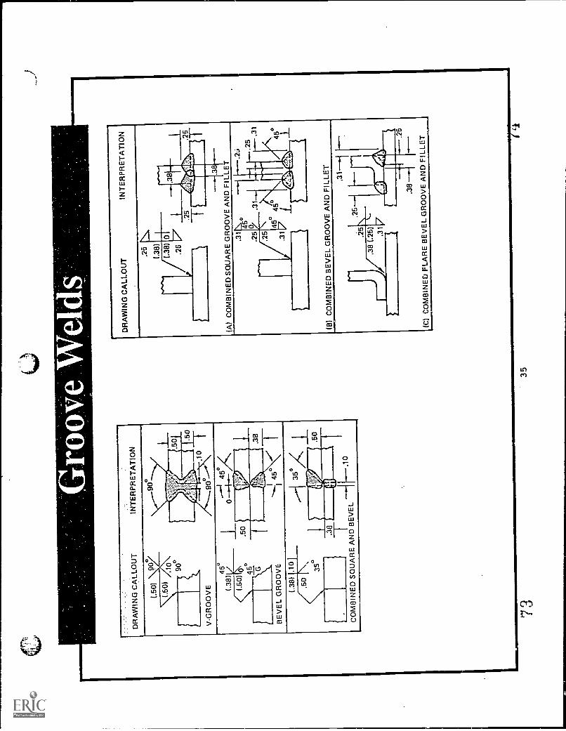
1.B
evel
-gro
ove,
J-g
roov
e, a
nd fl
are
beve
l-gr
oove
wel
d sy
mbo
ls a
real
way
s dr
awn
with
the
perp
endi
cula
r le
g to
the
left.
2.D
imen
sion
s of
sin
gle
groo
ve w
elds
are
show
n on
the
sam
e si
de o
f the
ref
eren
celin
e
as th
e w
eld
sym
bol.
3.E
ach
groo
ve o
f a d
oubl
e-gr
oove
join
t is
dim
ensi
oned
, how
ever
the
root
ope
ning
need
app
ear
only
onc
e.
4.F
or b
evel
-gro
ove
and
J-gr
oove
wel
ds, a
brok
en a
rrow
is u
sed,
whe
n ne
cess
ary,
toid
entif
y th
e m
embe
r to
be
prep
ared
.
DR
AW
ING
CA
LLO
UT
INT
ER
PR
ET
AT
ION
34
Oft
DR
AW
ING
CA
LLO
UT
INT
ER
PR
ET
AT
ION
(.50
)90
°0°
(.50
) /1
0
V-G
RO
OV
E
90°
IIIV
.k:i:
.50
,.5
0
.10
90°
(.50
)0
'45
°°
MM
.M
M.'3
8
......
0
BE
VE
L G
RO
OV
E
(.38
).1
0
350/
.50
35°
......
...1
.50
WU
. 8S
TC
OM
BIN
ED
SQ
UA
RE
AN
D B
EV
EL
-1F_
.,,,,
DR
AW
ING
CA
LLO
UT
INT
ER
PR
ET
AT
ION
.25
(.38
)
fl/L0
l.2
5Ir
l'
5*e
ft.3
8
5
1111
1111
1111
11
(A)
CO
MB
INE
D S
QU
AR
E G
RO
OV
E A
ND
FIL
LET
.31
.25
45-
0.3
1N
O
.25
.31
IJ5 .3
145
°°
45I/
cm..
(B)
CO
MB
INE
D B
EV
EL
GR
OO
VE
AN
DF
ILLE
T
.25
. 5
.31
.38
.31
igt
idilk III
IIa
.38
(C)
CO
MB
INE
D F
LAR
E B
EV
EL
GR
OO
VE
AN
DF
ILLE
T.26
733
5

(.0)
5.W
hen
no d
epth
of g
roov
e pr
epar
atio
n an
d no
groo
ve w
eld
size
are
spe
cifie
d on
the
wel
ding
sym
bol f
or s
ingl
e-gr
oove
and
sym
met
rical
dou
bleg
roov
e w
elds
, com
plet
ejo
int p
repa
ratio
n is
req
uire
d.
DR
AW
ING
.CA
LLO
UT
.-'.:
.':!'i
NT
BR
PR
ET
AT
ION
:..
,-
.06T
-.-1
[.*-
--.0
6.,
MO
AR
RO
W S
IDE
IMU
IllG
RIN
D F
LUS
H
---.
-1 k
--.0
6
40
\.._i
OT
HE
R S
IDE
.12
......
.\\60
°/..
...,.
60°
MI=
V
VG
RO
OV
E--
-.-1
F.-
.12
0 450
45°
all
BE
VE
L-,
--/-
*- 0
7536
1111
1111
1MM
ON
O'
76

6.W
hen
the
groo
ve w
elds
ext
end
only
par
tlyth
roug
h th
e m
embe
r be
ing
join
ed,
the
size
of
the
wel
d is
sho
wn
on th
e w
eld
sym
boi
3 7
,'::.:
T.,
.:',..
..-'.
...:..
.:::::
:'..'.
:.....
.. .
......
......
DR
AW
ING
QA
LLO
Ur
INT
ER
PA
ErA
TIO
N
(.76
).7
5
WIP
sSQUARE GROOVE
60°
060
.50
LI
1111
1110
PA
III
V-GROOVE
0
25°
0
.5
MI.
U-GROOVE
25°
.60
45°
(.50)
.06
45°
BEVEL GROOVE
.1GROOVE(.62)
-11
20 °
-
I
0
:.'
.62 T
11.7
%A
,-..1
20.\-
/) , Pi
0

7.A
dim
ensi
on n
ot in
par
enth
esis
pla
ced
to th
ele
ft of
bev
el, V
-, J
-, o
r U
-gro
ove
wel
dsy
mbo
ls in
dica
te o
nly
the
dept
hof
prep
arat
ion.
8.G
roov
e w
elds
that
are
to b
e w
elde
d w
ithap
prox
imat
ely
flush
or
conv
exfa
ces
with
out
post
-wel
d fin
ishi
ng a
re s
peci
fied
by a
ddin
gth
e flu
sn o
r co
nvex
con
tour
sym
bol t
o th
e
wel
ding
sym
bol.
9.G
roov
e w
elds
who
se fa
ces
are
to b
e fin
ishe
dbl
ush
or c
onve
x by
pos
twel
d fin
ishi
ng a
resp
ecifi
ed b
y ad
ding
bot
h th
e ap
prop
riate
cont
our
and
finis
hing
sym
bol t
o th
e w
eld
sym
bol.
Sta
ndar
d fin
ishi
ng s
ymbo
ls a
re:
C -
Chi
ppin
gG
- G
rindi
ngH
- H
amm
erin
gM
- M
achi
ning
R -
Rol
ling
10.
The
siz
e of
flar
e-gr
oove
wel
ds w
hen
now
eld
size
is g
iven
is c
onsi
dere
d as
ext
endi
ng o
nly
to th
e ta
ngen
t poi
nt in
dica
ted
bydi
men
sion
s
DR
AW
ING
CA
LLO
UT
INT
ER
PR
ET
AT
ION
FLA
RE
-V B
EV
EL
.25
.25
.38
(.50
)
.38
.50
r.5
.38
CO
MB
INE
D F
LAR
E-B
EV
EL
AN
DF
ILLE
T W
ELD
.25
DO
UB
LE F
LAR
E-B
EV
EL
.38
7938
80

8 1
DF
iAW
ING
CA
LLO
UT
..'IN
TE
RP
RE
TA
TIO
N.'
.
1.07
3-
01.0
010
wA \/
OR
Loo
SIZ
E O
F P
LUG
WE
LD
45°
0.50
.50
MN 45
°_
iNir
N.-
--A
NG
LE O
F P
LUG
WE
LD
5 .5
0
. 0-.
.--1
1-*-
0.75
i:P
AM
SI
7\ S
.
DE
PT
H O
F F
ILLI
NG
1.50
3.00
3,00
3.00
MIm
eg
41h,
Inab it!
AN
IFIII
MIN
IV
iP
ITC
H S
PA
CIN
G01
,00
1.00
60°
G
-..-
/.00
-H2,
006.
00-.
---
6 00
41fl
)o°
ti:N
1.00
V.I.
k.11
1111
1111
11.1
1
1.H
oles
in th
e ar
row
-wid
e m
embe
rof
a jo
int f
or
plug
wel
ding
are
spe
cifie
d uy
plac
ing
the
wel
d sy
mbo
l bel
ow th
e re
fere
nce
line.
2.H
oles
in th
e ot
her-
side
mem
ber
of a
join
t for
plug
wel
ding
are
indi
cate
d by
plac
ing
the
wel
d sy
mbo
l abo
ve th
e re
fere
nce
line.
3.T
he s
ize
of a
plu
g w
eld
is s
how
n on
the
sam
e si
de a
nd to
the
left
of th
e w
eld
sym
bol
4.T
he in
clud
ed a
ngle
of c
ount
ersi
nkof
plu
g
wel
ds is
the
user
's s
tand
ard,
unl
ess
othe
rwis
e in
dica
ted.
Incl
uded
ang
le, w
hen
not t
he u
ser's
sta
ndar
d, is
show
n.
0,7
6
1.00
11
45°
39

C
5.T
he d
epth
of f
illin
g of
plu
gw
elds
is c
ompl
ete
unle
ss o
ther
wis
e in
dica
ted.
Whe
nth
e de
pth
of ti
lling
is to
ss th
an c
ompl
ete,
the
dept
h of
fillin
g, in
inch
es o
r m
illim
eter
s, is
show
nin
side
the
wel
d sy
mbo
l.
7.P
lug
wel
ds th
at a
re J
be
wel
ded
with
appr
oxim
atel
y flu
sh o
r co
nvex
face
sw
ithou
t
post
wel
d fin
ishi
ng a
re s
peci
fied
by a
ddin
g
the
fiush
or
conv
ex c
onto
ursy
mbo
l to
the
wel
d sy
mbo
l.0°
.76
11
2.50
/1.00 1
.50
11.
003.
00
45°
0°'f,
1
6.P
itch
(cen
ter-
to-c
ente
r sp
acin
g)of
plu
gw
elds
is s
he n
to th
e rig
ht o
f the
wel
d
sym
bol.
.75
40°
8.P
lug
wel
ds w
hose
face
s ar
eto
be
finis
hed
appr
oxim
atel
y flu
sh o
r co
nvex
by p
ostw
eld
finis
hing
are
spe
cifie
d by
addi
ng b
oth
the
appr
opria
te c
onto
ur a
n fin
ishi
ngsy
mbo
l to
the
wel
ding
sym
bol.
Wel
dsth
at r
equi
re a
flat
but n
ot fl
ush
surf
ace
requ
ire a
nd e
xpla
nato
ry
note
In th
e ta
il of
the
sym
bol.
8340
.60
112
.00
G4
1"`
30°
.75
j2.
50
84

Fs.s
.. 1.
Slo
ts in
the
arro
w-w
ide
mem
ber
of a
join
t for
slot
wel
ding
are
indi
cate
d by
pla
cing
the
wel
d sy
mbo
l bel
ow th
e r
)fer
ence
line
. Slo
tor
ient
atio
n m
ust b
e sh
own
on th
e dr
awin
g.
2.S
lots
in th
e ot
her-
side
mem
ber
of a
join
t for
slot
wel
ding
are
indi
cate
d by
pla
cing
the
wel
d sy
mbo
l abo
ve th
e re
fere
nce
line.
3.D
epth
of f
illin
g sl
ot w
elds
is c
ompl
ete
unle
ssot
herw
ise
indi
cate
d. W
hen
the
dept
h of
filli
ngis
less
than
com
plet
e, th
e de
pth
of fi
lling
, in
inch
es o
r m
illim
eter
s, is
sho
wn
insi
de th
ew
eldi
ng s
ymbo
l.
.50
I TZ
,
DE
TA
IL A
1---
/---
F<
DE
T A
EX
AM
PLE
1S
LOT
S P
ER
PE
ND
ICU
LAR
TO
LIN
E O
F W
ELD
4.00
1-*-
--72
.09
L10
SLO
TS
EO
L S
PO
N 8
.00
CE
NT
ER
S
vt
.50
1,00
50H
DE
TA
IL 9
SLO
TS
PA
RA
LLE
L T
O L
INE
OF
WE
LD
4 1
S 5
8 6

4.Le
ngth
wid
th, s
paci
ng,
incl
uded
ang
le o
f
coun
ters
ink,
orie
ntat
ion,
and
loca
tion
of s
lot
wel
ds c
anno
t be
spec
ified
on
the
wel
ding
sym
bol.
The
se d
ata
are
to b
e sp
ecifi
ed o
n
the
draw
ing
or b
y a
deta
il w
ith .r
efer
ence
toit
on th
e w
eldi
ngsy
mbo
l.
<D
ET
C
5.S
lot w
elds
that
are
to b
ew
elde
d w
ith
apt o
xim
atel
yfin
ish
or c
onve
x fa
ces
with
out
post
wel
d fin
ishi
ng a
resp
ecifi
ed b
y ad
ding
the
finis
h or
con
vex
cont
our
sym
bol t
o th
e
wel
d sy
mbo
l.
6.S
lot w
elds
who
sefa
ces
are
to b
efin
ishe
d
appr
oxim
atel
y flu
sh o
r co
nvex
by p
ostw
eld
finis
hing
are
spe
cifie
dby
add
ing
both
the
appr
opria
te c
onto
uran
d fin
ishi
ng s
ymbo
lto
the
wel
ding
sym
bol.
Wel
ds th
at r
equi
re a
flab
but n
ot fl
ush
surf
ace
requ
ire a
n ex
plan
atio
n
note
in th
e ta
il of
the
sym
bol.
C
4288

DR
AW
ING
CA
LLO
UT
.25
GT
AW
GA
ST
UN
GS
TO
N-A
RC
SP
OT
0.25
1.T
he s
ymbo
lfor
all
spot
or
proj
ectio
n w
elds
is
a ci
rcle
,reg
ardl
ess
ofth
e w
eldi
ngpr
oces
s
used
. The
reis
not
atte
mpt
to p
rovi
de
sym
bols
ford
iffer
ent w
ays
of m
akin
g a
spot
wel
d, s
uch
asre
sist
ance
, arc
,an
d el
ectr
on
beam
wel
ding
.T
he s
ymbo
lfor
a s
pot
wel
d is
a ci
rcle
plac
ed:
Bel
ow th
ere
fere
nce
line,
indi
cate
d ar
row
side Abo
ve th
ere
fere
nce
line,
indi
cate
d ot
her
side On
the
refe
renc
e lin
e,in
dica
ting
that
ther
e is
no a
rrow
or o
ther
side
RE
SIS
TA
NC
E S
PO
T
(NO
AR
RO
W O
RO
TH
ER
SID
ES
IGN
IFIC
AN
CE
)
8943
90

2.D
imen
sion
s of
spo
t wel
ds a
resh
own
on th
e
sam
e si
de o
fthe
ref
eren
ce li
ne a
s th
ew
eld
sym
bol.
or o
n ei
ther
sid
ew
hen
the
sym
bol i
s
loca
ted
astr
ide
the
refe
renc
elin
e an
d ha
s
not a
rrow
-sid
e or
oth
ersi
de s
igni
fican
ce.
The
y ar
e di
men
sion
ed b
yei
ther
the
size
or
the
stre
ngth
. The
sid
e is
desi
gnat
ed a
s th
e
diam
eter
of t
he w
eld
at th
efa
ying
sur
face
san
d is
sho
wn
to th
e le
ft of
the
wel
d sy
mbo
lT
he s
tren
gth
of th
e sp
otw
eld
is d
esig
nate
din
pou
nds
or n
ewto
ns p
er s
pot
and
is s
how
n
to th
e le
ft of
the
wel
dsy
mbo
l.
//71-
27:T
\
SP
EC
IFY
ING
DIA
ME
TE
R O
FS
PO
T
7-T
5-C
Y<
SP
EC
IFY
ING
ST
RE
NG
TH
OF
SP
OT
it; .120 ..1
44
3.T
he p
roce
ss r
efer
ence
is to
be in
dica
ted
in
the
tail
of th
e w
eldi
ngsy
mbo
l.
RS
W
4.W
hen
proj
ectio
n w
eldi
ngis
use
d, th
e sp
otw
eld
sym
bol i
s us
ed a
ndth
e pr
ojec
tion
wel
ding
pro
cess
isre
fere
nced
in th
e ta
il of
the
sym
bol.
The
spo
twel
d sy
mbo
l is
loca
ted
abov
e or
bel
ow (
not o
n)th
e re
fere
nce
line
to
desi
gnat
e on
whi
ch m
embe
rth
eem
boss
men
t is
plac
ed.
5.T
he p
itch
(cen
ter-
to-c
ente
rsp
acin
g) is
show
n to
the
right
of t
hew
eld
sym
bol.
150
0 6.
00
9 ''

6.W
hen
spot
wel
ding
ext
ends
less
than
the
dist
ance
bet
wee
nab
rupt
cha
nges
in th
e
dire
ctio
n of
the
wel
ding
or
less
than
the
full
leng
th o
f the
join
t, th
e ex
tent
is d
imen
sion
ed.
.18
W 2
.00
24.0
02.
50
(A)
DR
AW
ING
CA
LLO
UT
2.50
2 00
2.00
2,00
INT
ER
( R
ET
AT
ION
SS45
Whe
re th
eex
pose
d su
rfac
eof
eith
er
mem
ber
of a
spot
wel
ded
join
t is
to b
e
wel
ded
with
appr
oxim
atel
yflu
sh o
r co
nvex
face
s w
ithou
tpost
wel
d fin
ish,
that
sur
face
is
spec
ified
by
addi
ng th
eflu
sh o
r co
nvex
cont
our
sym
bolt
o th
e w
eld
sym
bol.
8.S
pot w
elds
who
se fa
ces
are
to b
e fin
ishe
d
appr
oxim
atel
yflu
sh, o
r co
nvex
by p
ostw
eld
finis
hing
are
spec
ified
by
addi
ng b
oth
the
appr
opria
te c
onto
uran
d fis
hing
sym
bol t
o
the
wel
ding
sym
bol.
Wel
dsth
at r
equi
res
a
flat b
ut n
otflu
sh s
urfa
cere
quire
and
expl
anat
ory
note
in th
e ta
il of
the
sym
bol.
M\_
_eL
MA
CH
INE
.>F
LAT
0
94

DR
AW
ING
CA
LLO
UT
INT
ER
PR
ET
AT
ION
II.R
SE
W,2
520
0 -
4:00
-.12
,00
2,00
2.00
I-- 5
1 elow
li:M
arvs
s%C
IOnc
ian
I, 41
1111
4111
1111
.111
111
SE
CT
ION
TH
RO
UG
H,..
.,ELD
SIZ
E, L
EN
GT
HA
ND
PIT
CH
SE
AM
WE
LD
4.00
OF
(R
ES
IST
AN
CE
)4.
00
,...
EB
W20
0 m
og
\S
TR
EN
GT
H O
F(E
LEC
TR
ON
BE
AM
)S
EA
M W
ELD
GT
AW
..,.2
5 am
1.61
1161
1111
1.
H6,
00r-
600
SE
CT
ION
TH
RO
UG
H W
ELD
EX
TE
NT
OF
(G
AS
TU
NG
ST
EN
AR
C)
SE
AM
WE
LD
BE
ST
CO
PY
AV
AIL
AB
LE
1.T
he s
ymbo
l for
all s
eam
wel
dsis
a c
ircle
trav
erse
d by
two
horiz
onta
l par
alle
llin
es.
Thi
s sy
mbo
l is
used
of a
ll se
amw
elds
rega
rdle
ss o
f the
way
they
are
mad
e.T
he
seam
wel
dssy
mbo
l is
plac
ed(1
) be
low
the
refe
renc
e lin
e to
indi
cate
arr
oww
ide,
(2)
abov
e th
e re
fere
nce
line
to in
dica
teot
her
side
, and
(3)
on
the
refe
renc
eH
ine
to in
dica
te
that
ther
e is
not
arro
w o
rot
her
side
sign
ifica
nce.
2.D
imen
sion
s of
sea
mw
elds
are
sho
wn
onth
e
sam
e si
deof
the
refe
renc
elin
e as
the
wel
d
sym
bol o
r al
loth
er e
ither
sid
ew
hen
the
sym
bol i
s ce
nter
edon
the
refe
renc
e lin
e.
414
.544
/
SP
EC
IFY
ING
WID
TH
OF
WE
LD
r .
SP
EC
IFY
ING
ST
RE
NG
TH
OF
WE
LD
9'47
96

3.T
he p
roce
ssre
fere
nce
isin
dica
ted
in th
eta
il
of th
ew
eldi
ng s
ymbo
l.
4.T
he le
ngth
of a
sea
mw
eld,
whe
nin
dica
ted
on th
ew
eldi
ng s
ymbo
l,is
sho
wn
toth
e rig
ht
of th
e w
eld
sym
bol.
whe
nse
amw
eldi
ng
exte
nds
for
the
full
dist
ance
betw
een
abru
pt
chan
ges
in th
edi
rect
ion
ofth
e w
eldi
ng,
not
leng
thdi
men
sion
sne
eds
to b
esh
own
on th
e
wel
ding
sym
bol.
Whe
n a
seam
wel
dex
tend
s
less
than
the
full
leng
th o
f the
join
, the
exte
nd o
f the
wel
d sh
ould
be s
how
n.
.25
3gE
8.00
<
1111
1,11
1111
1/11
1111
111M
i-
2.00
.25
12 0
0
5.T
he p
itch
of a
nIn
term
itten
t sea
mw
eld
is
show
n as
the
dist
ance
betw
een
cent
ers
or
the
wel
din
crem
ents
. The
pitc
h is
show
n to
the
right
oft
he le
ngth
dim
ensi
on.
2:0C
-4:
00
6.W
hen
the
expo
sed
surf
ace
of e
ither
mem
ber
of a
seam
wel
ded
join
tis
to b
ew
elde
d w
ith
appr
oxim
atel
yflu
sh o
r co
nvex
face
s w
ithou
t
post
wel
dfin
ishi
ng th
atsu
rfac
e is
spec
ified
by
addi
ng th
eflu
sh o
r co
nvex
cont
our
sym
bolt
o
the
wel
dsy
mbo
l.
<
7.S
eam
wel
dsw
ith fa
ces
tobe
fini
shed
appr
oxim
atel
hflu
sh o
r co
nvex
are
spec
ified
by a
ddin
gbo
th th
eap
prox
imat
eco
ntou
r an
d
finis
h sy
mbo
lto
the
wel
ding
sym
bol.
48
It>
/---
PY
AV
AIL
AB
LE98

':DR
A:I.
1G C
ALL
OU
TIN
TE
RP
RE
TA
TIO
N
a=3
NO
T D
ET
AIL
ED
DE
TA
ILE
D
ED
GE
-F L
AN
GE
NO
T D
ET
AIL
ED
DE
TA
ILE
DC
OR
NE
R-F
LAN
GE
ED
GE
-FLA
NG
E W
ITH
ME
LTT
HR
OU
GH
WE
LD
NO
T D
ET
AIL
ED
DE
TA
ILE
D
LG9N
ER
-F L
AN
GE
WIT
HM
ELT
-TH
RO
UG
H W
ELD
.17
7-72
.T1
.09
.25
The
follo
win
g w
eldi
ng s
ymbo
lsar
e in
tend
ed to
be
used
for
light
-gag
em
etal
join
ts in
volv
ing
the
flarin
g
or fl
angi
ng o
fthe
edg
es to
be
join
ed.
1.E
dge-
flang
e w
elds
are
show
n by
the
edge
-
flang
e-w
eld
sym
bol.
2.C
orne
r-fla
nge
wel
ds o
n jo
ints
deta
iled
on th
e
draw
ing
are
spec
ified
by
the
corn
er-f
lang
ew
eld
sym
bol.,
Wel
d sy
mbo
lsar
e al
way
s
draw
n w
ith th
e pe
rpen
dicu
larl
eg to
the
left.
3.C
orne
r-fla
nge
wel
ds o
n jo
ints
not d
etai
led
on
the
draw
ing
are
spec
ified
by
the
corn
er-
flang
e w
eld
sym
bol.
A b
roke
n ar
row
poi
nts
to
the
mem
ber
bein
g fla
nged
.
NO
T D
ET
AIL
ED
DE
TA
ILE
D
ED
GE
F L
AN
Gt7
. DIM
EN
SIO
NS
It
NO
T D
ET
AIL
ED
DE
TA
ILE
D.0
9
CO
RN
ER
-FLA
NG
E D
IME
NS
ION
S
491.
3ES
T C
OP
Y A
VA
ILA
BLE
0 0

4.E
dge-
flang
e w
elds
req
uirin
gco
mpl
ete
join
t
pene
trat
ion
are
spec
ified
by th
e ed
ge-f
lang
e
wel
d sy
mbo
l with
the
mel
t-th
ough
sym
bol
plac
ed o
n th
e op
posi
te s
ide
of th
e re
fere
nce
line.
The
sam
e w
eldi
ngsy
mbo
l is
used
for
join
ts e
ither
det
aile
d or
not
deta
iled
on th
e
draw
ing.
5.C
orne
r-fla
nge
wel
ds r
equi
ring
com
plet
ejo
int
pene
trat
ion
are
spec
ified
by
the
corn
er-
flang
e w
eld
sym
bol w
ith th
em
elt-
thro
ugh
sym
bol p
lace
d on
the
oppo
site
side
of t
here
fere
nce
line.
A b
roke
n ar
row
poi
nts
toth
em
embe
r to
be
flang
ed w
here
the
join
t is
not
deta
iled.
JOIN
T D
ET
AIL
ED
JOIN
T N
OT
DE
TA
ILE
D
6.D
imen
sion
s of
flan
ge w
elds
are
show
n on
the
sam
e si
de o
f the
refe
renc
e lin
e as
the
wel
d sy
mbo
l The
rad
ius
and
the
heig
ht,
sepa
rate
d by
a p
lus
(+)
are
plac
ed to
the
left
of th
e w
eld
sym
bol.
The
rad
ius
and
the
heig
ht r
ead
in th
at o
rder
from
left
to r
ight
alon
g th
e re
fere
nce
line.
R+
TH
IR
;H
WH
ER
E T
WE
LD T
HIC
KN
ES
SH
. H
EIG
HT
OF
FLA
NG
ER
RA
DIU
S O
F F
LAN
GE
7.T
he s
ize
(Thi
ckne
ss)
offla
nge
wel
ds is
spec
ified
by
a di
men
sion
plac
ed a
bove
or
belo
w th
e fla
nge
dim
ensi
ons.
.09
.12+
.05
I.1
24-.
061
.05
50
102