Embed Size (px)
Citation preview

ED 089 086
TITLE
INSTITUTION
REPORT NOPUB DATENOTE
AVAILABLE FROM
EDRS PRICEDESCRIPTORS
IDENTIFIERS
ABSTRACT
DOCUMENT RESUME
CE 001 141
Ground Instructor Written Test Guide--Basic-Advanced.Revised 1972.Federal Aviation Administration (DOT), Washington,D.C. Flight Standards Service.AC-143-1C7256p.; The aeronautical chart included with thedocument is not available through ERICSuperintendent of Documents, U.S. Government PrintingOffice, Washington, D.C. 20402 (Stock Number5011-00062, $1.25)
MF-$0.75 HC-$3.15 PLUS POSTAGEAviation Technology; Intentional Learning; *NationalCompetency Tests; *Study Guides; TestsAviation; *Ground Instructor Written Test
The test guide was prepared to assist applicants whoare preparing for the Ground Instructor Written Test. It supersedesthe 1967 examination guide. The guide outlines the scope of the basicaeronautical knowledge requirements for a ground instructor;acquaints the applicant with source material that may be used toacquire this basic knowledge; and presents sample test items withanswers, explanations, and illustrations representative of those usedin the current Ground Instructor Written Test. An appendix containsweather information, aircraft description, performance data, theflight planning data, excerpted information from the *Airman'sInformation Manual,* diagrams, charts, and illustrations related tosome of the test questions. (Author/AG)

es,
El Ground InstructorWritten Test Guide
1)
(L) DEPARTMENT OF TRANSPORTATION
Basic Advanced
AC 143-1C
U.S, DEPARTMENT OF HEALTH,EDUCATION t WELFARENATIONAL INSTITUTE OF
EDUCATIONTHIS DOCUMENT HAS BEEN REPRODUCED EXACTLY AS RECEIVED FROMTHE PERSON OR ORGANIZATION ORIGINAT ING IT POINTS OF VIEW OR OPINIONSSTATED DO NOT NECESSARILY REPRESENT OFFICIAL NATIONAL INSTITUTE OFEDUCATION POSITION OR POLICY
It'
FEDERAL AVIATION ADMINISTRATION

- DEPARTMENT OF TRANSPORTATIONFEDERAL AVIATION ADMINISTRATION
FLIGHT STANDARDS SERVICE
Ground Instructor
WRITTEN TEST GUIDE
Basic-Advanced
REVISED
1972
For sale by the Superintendent of Documents, U.S. Government Printing OfficeWashington, D.C. 20402. Price: $1.25, domestic postpaid; $1, GPO Bookstore
Stock No. 5011-00062

Preface
This test guide was prepared by the Federal Aviation Administration as AdvisoryCircular AC 143-1C to assist applicants who are preparing for the Ground InstructorWritten Test. It supersedes the Ground Instructor Examination Guide, AC 143-1B,issued in 1967.
This guide outlines the scope of the basic aeronautical knowledge requirementsfor a ground instructor; acquaints the applicant with source material that may beused to acquire this basic knowledge; presents sample test items with answers andexplanations, and illustrations representative of those used in the current GroundInstructor Written Test.
Comments regarding this publication should be directed to the Department ofTransportation, Federal Aviation Administration, Flight Standards Technical Division,P.O. Box 25082, Oklahoma City, Oklahoma 73125.
iii

ContentsPage
Preface iiiIntroduction 1
Nature of Test 1
Type of Test Questions 1
Taking the Test .. 1
Recommended Study Materials 3
How to Obtain GPO Publications 4
Study OutlineSample Test 15
Answers and Explanations 23
AppendixFigure 1. Station identifiers 29
Figure 2. Letter designators for reports and forecasts 29
Figure 3. Area forecasts 30
Figure 4. Terminal forecasts, winds aloft forecasts, and in-flight weather advisories 31
Figure 5. Pilot report summaries and hourly sequence reports 32
Figure 6a. Daily weather map excerpt 33
Figure 6b. Daily weather map-station weather 34
r igure 7. Standard time zones and conversion to Greenwich (Z) time 35
Figure 8. Aircraft description placard (excerpt from Airplane Flight Manual) ----- 36
Figure 9. Radio equipment and compass correction card 37
Figure 10. Center of gravity envelope and loading graph 37
Figure 11. Weight and balance 38
Figure 12. Takeoff, climb, and landing distance tables 39
Figure 13. Cruise performance chart 40
Figure 14. Airport/facility directory 41
Figure 15. Airport/facility directory 42
Figure 16. Airport/facility directory 43
Figure 17. Airport/facility directory 44
Figure 18. Airport/facility directory 45
Figure 19. Airport directory 46
Figure 20. Notices to Airmen 47
Figure 21. The Airspace (cruising altitudes) 48
Figure 22. Excerpts from Procedural Regulation, Part 430 49
Figure 23. The Lambert conformal chart projection 50
Figure 24. Altimeter readings 50
Figure 25. Radio compass (ADF) 51
Figure 26. Flight instruments 51
Figure 27. Load factor chart 52
Figure 28. ADF indications 53
Figure 29. VOR navigation receiver indications 53
Figure 30. Example of Flight Plan (VFR) 54
Figure 31. Light gun signals used in airport traffic control 54
Figure 32. Airspeed correction table 55
V

GROUND INSTRUCTOR WRITTEN TEST GUIDEFUNDAMENTALS OF INSTRUCTING
BASIC-ADVANCED
IntroductionThis study guide was prepared by the Flight
Standards Service of the Federal Aviation Admin.istration. Its main purpose is to assist applicantswho are preparing for the Basic or AdvancedGround Instructor Written Test. It is not offeredas a quick and easy way to gain the knowledgenecessary for passing the written test. Knowledgeand understanding are seldom gained quickly oreasily. This is particularly true in the diversifiedfield of aviation ground instruction. There can beno substitute for diligent study to attain basicknowledge, unremitting effort to develop compe-tence, and continuous review to remain current inthe many areas where technological change is therule rather than the exception.
Another purpose of this guide is to provideguidance for the serious student by outlining thescope of knowledge required. Thus, the student isbetter able to intelligently direct his study plan.
Nature of the TestMuch of the information and knowledge required
of the instructor in aviation ground subjects isessentially the same today as it was many yearsago, yet there has been a gradual and definitechange in some areas. Technological advancementsand refinements in today's aircraft, plus the increased use made of their capabilities by the generalflying public, have outmoded the practice of testingfor memory alone. Of course, basic knowledge isstill necessary but it must be related to the opera-tionally realistic situation. An aircraft's primarycommercial use is to provide safe, speedy, andefficient transportation and all civilian training,flight or ground, is directed toward this end. Forthis reason, knowledge must be related to skill, andskill is inextricably interwoven with knowledge.Therefore, written tests today require the abilityto use basic knowledge in practical situations aswell as in answering questions based on theoreticalproblems.
For this reason, the guide will deal with ques-tions that test for knowledge alone, as well as
questions that test for the ability to apply and usethis knowledge in a realistic environment. Someof the questions will deal with specific subjects(navigation, radio navigation, meteorology, FederalAviation Regulations, aircraft, and powerplants)and test for basic knowledge and grasp of theoryin regard to fundamentals of instructing. Otherquestions will require the ability to combine andsynthesize knowledge in two or more of the specificsubject areas.
The FAA written tests your students will takeare of similar format and nature with regard torequiring competence at practical application oftheory and knowledge. Knowing this should enable you to organize course material and directclassroom efforts so that your students will be wellprepared for their tests.
Type of Test QuestionsThe test questions are of the objective, multiple.
choice type as illustrated by questions in the sampletest. Each question can be answered on a specialanswer sheet with a pencil mark. To preclude thepossibility of an applicant receiving a failing gradebecause of a mistake in grading, all tests scoredbelow passing are rechecked by trained personnel.
Taking the TestThe equipment that the applicant will need for
taking the test includes a protractor or plotter anda computer. It is also desirable to have a pair ofdividers. The times allowed for completion are:
A. Basic 4 hoursB. Advanced 5 hoursC. Fundamentals of Instructing 2 hours
(It is not necessary to take the Funda-mentals of Instructing on the same day asthe Basic or Advanced test.)'
While it may be possible to complete the test inless time, it would be unwise to plan on this. If itbecomes necessary to hurry, it may increase theprobability of mistakes.
1

Always remember the following facts when youare taking the test:
1. The questions are not trick questions. Eachstatement means exactly what it says. Do not lookfor hidden meanings. The statement does not con-cern exceptions to the rule; it refers to the generalrule.
2. Always read the statement or question firstbefore you look at the answers. Be sure you readthe entire question carefully. Avoid "skimming"and hasty assumptions. This may lead to an er-roneous approach to the problem or failure toconsider vital words.
3. Only one of the alternate answers given iscompletely correct. Other answers may be correctas far as they go, but are not complete or areanswers based on erroneous assumptions, miscon-ceptions, or incorrect procedures and interpreta-tions. Understand the question or statement.Then work out your answer before choosing fromthe list of alternate answers the response which youconsider to be the best.
4. Do not spend too much time on a questionwhich you cannot solve or on one where you havedoubt as to the correct answer. By so doing, youdeprive yourself of the opportunity to mark all
AMP
2
those questions which you can promptly solve oranswer. You may always go back to the questionsyou skipped after you are through with all thosewhich you can readily answer. Many times youcould have answered five or 10 questions duringthe time you work with one that is difficult. Thisprocedure will enable you to make maximum useof the time available. It may mean the differencebetween a passing and a failing score.
5. In solving problems which require compu-tations or use of the plotter and computer, selectthe answer which is closest to the result you get.Due to slight differences in individual computersand small errors you may make in measuringdistances, true courses, etc., it is possible that youwill not get an exact agreement every time. Suf-ficient spread is provided between right and wronganswers, however, so that the selection of the answer closest to your solution will be the right choice,providing you have used correct technique andreasonable care in making your computations.
NOTE: When the test is constructed, various types ofnavigational computers are used to solve problems. Thecorrect answer is an average of these computers; therefore,any one of the several types of computers authorized foruse on FAA written tests should prove satisfactory.

RECOMMENDED STUDY MATERIALSThe prospective Ground Instructor will find the
following list of publications useful in his prepara-tion for the written test. In addition, there aremany other excellent commercially prepared text-books, audiovisual training aids, and other instruc-tional materials which may be helpful.
AERONAUTICAL CHARTS
The National Ocean Survey publishes and dis-tributes aeronautical charts of the United States.Charts for foreign areas are published by the U.S.Air Force Aeronautical Chart and InformationCenter (ACIC) and are sold to civil users by theNational Ocean Survey.
A "Catalog of Aeronautical Charts and RelatedPublications" listing their prices and instructionsfor ordering may be obtained free, on request,from:
Distribution Division, (C-44)National Ocean SurveyWashington, D.C. 20235
Orders for specific charts or publications shouldbe accompanied by check or money order madepayable to "NOS, Department of Commerce".
Airman's Information Manual. This publicationpresents, in four Parts, information necessary forthe planning and conduct of flights in the U.S.national airspace. Besides providing frequentlyupdated airport and NAVAID data, the AIM in-cludes instructional and procedural information andis designed for use in the cockpit.
Each Part is available on a separate annual sub-scription to better serve the needs of the individual Ipilot.
Part 1. Basic Flight Manual and A7'C Procedures (Annual subscription $4, Foreign mailing$1 additional. GPO.) Catalog No. TD 4.12:Pt.1/.Issued quarter'!.
Part 2. Airport Directory (Annual subscription$4, Foreign mailing$1 additional. GPO.) Cata-log No. TD 4.12:pt.2/. Issued semiannually.
Part 3. Operational Data and Notices to Airmen(Annual subscription $20, Foreign mailing$5additional. GPO.) Catalog No. TD 4.12:pt.3/.Issued every 28 days, supplemented by Part 3A(Notices to Airmen) every 28 days between issuesof Part 3.
496 -224 0. 73 . 2
Part 4. Graphic Notices and Supplemental Data(Annual subscription $1.50, Foreign mailing$0.50 additional. GPO.) Catalog No. TD 4.12:pt.4/. Issued semiannually.
HANDBOOKS AND TECHNICAL MANUALS
Pilot's Handbook of Aeronautical Knowledge.AC 61-23A ($4.00GPO.) Catalog No. TD4.408:P ,,64/5. This handbook contains essential,authoritative information used in training and guid-ing pilots. Subject areas in which an applicantmay be tested are covered in the handbook. Ittells how to use the Airman's Information Manualand the data in FAA-approved airplane flightmanilas, as well as basic instruments for airplaneattitude control.
Personal Aircraft Inspection Handbook. AC20-9 ($1.50GPO.) Catalog No. FAA 5.8/2:Ai7/2. This is a general guide for inspection of air-craft; Part I deals with the fundamentals of inspec-tion and Part II covers a typical inspection in detail.As reliable inspection comes only with experience,it is emphasized that the use of this handbook bythe novice does not qualify him to make final de-terminations regarding the airworthiness of the air-craft. This handbook supersedes TM-101 dated1950.
Flight Instructor's Handbook. AC 61-16A($2.00 GPO.) Catalog No. TD 4.408:In 7/3.This revised handbook is one of the primarysources of information and guidance for pilots pre-paring for the flight instructor written test. It isbasically a book which explains accepted theoriesand practices applicable to teaching and the learn-ing process. Therefore, it will also prove mostuseful to those preparing for the Fundamentals ofInstructing section of the Ground Instructor WrittenTest.
Flight Training Handbook. AC 61-21 ($1.25GPO.) Catalog No. FAA 1.8:F 64/4. This textdeals with certain basic flight information such asload factor principles, weight and balance, and re-lated aerodynamic aspects of flight, as well asprinciples of safe flight. This book also providesinformation and direction in the introduction andperformance of training maneuvers. Thus it servesprimarily as a text for student pilots, for pilotsimproving their qualifications or preparing for
3

additional ratings, and for flight instructors; how-ever, it can also be useful to the ground instructor.
NAVIGATION AND WEATHER
Practical Air Navigation. 10th Edition. ($4.00).This publication provides a comprehensive coverage of all subjects and areas dealing with naviga-tion whether it bo pilotage, dead reckoning, orradio and celestial navigation. Students who understand the material available in this highlyrecommended text will have no serious troublewith the navigation problems on their test. Thistext may be obtained from many book dealers orfrom the publisher, Jeppesen & Co., 8025 East 40thAve., Denver, Colorado 80209.
Aviation Weather. AC 00-6 ($4GPO.) Cata-log No. FAA 5.8/2:W 37. Contains informationon weather phenomena for pilots and other flightoperations personnel whose interest in meteorologyis primarily in its application to flying.
Federal Aviation Regulations (FARs). Thesubscription prices listed include automatic revisionservice to all Parts contained in the Volume ordered.The FAR Parts contained in each Volume are listedin the "Advisory Circular Checklist and Status ofFederal Aviation Regulations," obtainable free onrequest from FAA.
Vol. I, Part 1, DefinitionsPrice
Additional ForForeignMailing
and Abbreviations ____ $2.50 $0.50Vol. IX, Part 61, Certifi-
cation: Pilots & FlightInstructors, and Part141, Pilot Schools, andPart 143, Ground In-structors $6.00 $1.50
Vol. VI, Part 91, GeneralOperating and FlightRules $9.00 $2.00
NATIONAL TRANSPORTATION SAFETY BOARD
Procedural Regulation, Part 430. (FREE fromNTSB.) This publication deals with proceduresrequired in dealing with accidents and lost or over-due aircraft in the United States, its territories andpossessions.
TRAINING AIDS
Commercial Pilot Written Test Guide. 1970 AC61-28A ($1.50GPO.) Catalog No. TD 4.408:P64/4. This guide gives detailed information on thescope and depth of knowledge required of thecommercial pilot applicant.
4
VFR and IFR ExamO-Grams. Brief, timely, andgraphic 'articles developed and published on a continuing basis. They are nondirective in nature andare issued as an information service, particularlyto individuals Interested in airman written tests.They relate to concepts, practices, and procedurescritical to aviation safety and assist in givingsafety-oriented information to airman applicantsand practicing airmen. ExamO-Grams are avail-able free of charge, but are limited to single copyper request. Requests for placement on the mailinglist should be addressed to:
Department of TransportationFederal Aviation AdministrationFlig.It Standards Technical DivisionOperations Branch, AAC-240P.O. Box 25082Oklahoma City, Oklahoma 73125
How To OBTAIN GPO PUBLICATIONS
1. Use an order form, not a letter unless abso-lutely necessary. Order forms, which may beduplicated by the user, are included in the catalog"FAA Publications," sent free upon request from:
Distribution Unit, TAD 484.3Department of TransportationWashington, D.C. 20590
2. Send separate orders for a subscription and anonsubscription item.
3. Give the exact name of the publication andthe agency number.
4. Send a check or money order, not cash. Sendthe exact amount.
5. Enclose a self-addressed mailing label if youhave no order blank.
6. Use special delivery when needed.
7. Use GPO bookstores.
Several GPO bookstores have been establishedthroughout the country for sale.of publications. Thepublic is encouraged to avail themselves of themail order service offered by these facilities.
GPO bookstores are located at the followingaddresses:GPO BookstoreRoom 100, Federal Building275 Peachtree Street NEAtlanta, Georgia 30303
GPO BookstoreRoom 102A, 2121 Building2121 Eighth Avenue NorthBirmingham, Alabama 35203
GPO BookstoreRoom G25, John F. Kennedy Federal BuildingSudbury StreetBoston, Massachusetts 02203
GPO BookstoreFederal Office Building201 Cleveland Avenue SWCanton, Ohio 44702
GPO BookstoreRoom 1463-14th FloorEverett McKinley Dirksen Building219 South Dearborn StreetChicago, Illinois 60604
GPO BookstoreRoom 1C46Federal BuildingU.S. Courthouse1100 Commerce StreetDallas, Texas 75202
GPO BookstoreRoom 1421Federal BuildingU.S. Courthouse1961 Stout StreetDenver, Colorado 80202
GPO BookstoreRoom 229, Federal Building231 W. Lafayette Blvd.Detroit, Michigan 48226
GPO BookstoreRoom 135, Federal Office Building601 East 12th StreetKansas City, Missouri 64106
GPO BookstoreRoom 1015, Federal Office Building300 North Los Angeles StreetLos Angeles, California 90012
GPO BookstoreRoom 11026 Federal PlazaNew York, New York 10007
GPO BookstoreU.S. Post Office and CourthouseMain LobbyNinth and Chestnut StreetsPhiladelphia, Pennsylvania 19107
GPO BookstoreRoom 1023, Federal Office Building450 Colden Gate AvenueSan Francisco, California 94102
Mail orders may also be directed to:Superintendent of DocumentsU.S. Government Printing OfficeWashington, D.C. 20402
5/6

STUDY OUTLINE
The study outline which follows is the frameworkfor basic aeronautical knowledge that the prospective ground instructor must know ; every questionon the FAA test can be directly related to one ormore of the topics contained in this outline. Thissubject matter is predicated on both theoreticalquestions in specific areas and on operationallyrealistic airman activity, and encompasses theknowledge requirements specified in Federal Aviation Regulations.
Section 1
Fundamentals of Instructing1. The Ground Instructor-Desirable Qualities.
A. Good attitude toward teaching.1. Desire to do a competent job.2. Ability to develop and improve.3. Sincerity, enthusiasm, and patience.
H. The Pattern for Instruction-How to Guide theLearning Process.
A. Understand the factors, conditions, and prin-ciples which guide the learning process.
1. Establish clear objectives.2. Provide for student participation.3. Develop understanding and insight.4. Develop ability to think and reason through
use of known facts.5. Use of motivation, presentation, trial per.
formance, and evaluation.
III. Planning-Vital to Teaching Success.A. Diagnose present stuic..t ability and ability
desired upon completion of course.B. Arrange teaching sequence to "make sense".
1. Proceed from the known to the unknown.2. Proceed from the easy to the difficult.3. Plan so student will see necessity and logic
of each succeeding step.4. Use a lesson plan-know its advantages.
IV. Presentation-Procedure to Follow.A. Plan.
1. Studentinstructor relations-establish anatmosphere of cooperation.
2. Direct and explain.3. Discuss.
a. Get all students to participate.b. Keep discussion moving toward goal.c. Emphasize important points.d. Keep explanation short, clear, and to the
point.4., Question technique--its use and importance.5. Use analogies as a link between known and
unknown.6. Use instructional aids.
V. Performance, Practice, and Application.A. Steps to follow.
1. Start with the easy and work toward thedifficult.
2. Make performance realistic.3. Guide student's efforts.4. Get each student to participate.5. Relate performance to previous explanations
and directions.6. Provide adequate practice but guard against
blind "trial and error".7. Evaluate student progress.
VI. Motivation-Basic to All Learning.A. Reward-use and limitations.
B. Immediate and long.range goals and theirrelative usefulness.
C. Arousing interest.1. Use of student's background.2. Use of your own experience and back.
ground.3. Use of anecdotes and stories.
D. Conditions detrimental to good motivation.1. Self-consciousness.2. Antagonism.3. Impatience.4. Worry.5. Physical discomfort.6. Boredom.
VII. Teaching Methods and Techniques.A. Telling-sometimes called the "lecture"
method.1. Does not permit student participation.2. Can be combined with other methods to be
more effective.
7

B. Discussions--techniques of.1. Develop cooperative spirit.2. Clarify problems.3. Encourage participation.4. Avoid dominating discussion.5. Summarize frequently.
C. Demonstrations or showing.1. Must be combined with telling.2. Advantages.
a. Makes explanations concrete.b. Aids student understanding.c. Saves learning time.d. Effective with large groups.e. Gives students overall perspective.f. Appeals to several senses.g. Has dramatic appeal.
D. Performing or DoingEssential to the Learn.ing Process.
1. Techniques.a. Plan the performance.b. Prepare the student for performance.c. Guide the performance.d. Give individual attention.e. Evaluate the performance.f. Have the student evaluate the perform.
ance.g. Practice the performance.h. Supervised study--a form of performance.
(1) Surveystudent must get a pictureof the problems.
(2) Assign reading material.(3) Student must practice selfquestion
ing.(4) Recite.(5) Reviewnecessary to develop and
firmly fix learning and improve weaknessrevealed by recitations.
(6) Cliiquean analysis of performance.E. Test Administration ProceduresPreceding,
During, and After Student Participation.1. Preceding.
a. Be on time.b. Check tests for errors.c. Give clear instructions.d. Create relaxed atmosphere.
2. During.a. Avoid distractions.b. Limit student discussions.c. Be alert to student need for permissible
assistance.3. After.
a. Review.b. Permit constructive student criticism
written and oral.
8
F. EvaluationThe measure of Success of Teach.ing Program.
1. What to test.a. Understanding.b. Actual performanceability to apply
knowledge to realistic problems is the onlypositive assurance of mastery of subject.2. Characteristics of Good Evaluation Devices.
a. Validitydoes it measure what it issupposed to measure?
b. Reliabilityare the results consistent?c. Objectivitylimit personal judgments.d. Differentiatetest must measure small
but significant differences in achievement.e. Comprehensiveprovide adequate sam
piing.3. Types of tests.
a. Multiple.choice.b. Matching.c. TrueFalse.d. Completion.e. Essay.
G. Instructional AidsChoose the Aid that Fitsthe Learning Situation.
1. Usual types of aids.a. Films, strips, slides.b. Training graphicsdiagrams, charts, pic
tures, etc.c. The blackboard.d. Training devicesmockups, schematics,
operational, sectionalized, and exploded.e. Training literature.f. Field trips.
2. Caution in the use of instructional aids.a. Contribute little unless they develop stu
dent understanding.b. Don't expect them to do your teaching.
VIII. StudentInstructor Relationship.A. Establish receptive, cooperative working re.
lationship.1. Be natural, enthusiastic, and helpful.2. Realize you are dealing with men, not ma.
chines.3. Be a guide, not a driver.4. Treat students as adultsdo not talk down
to them.5. Be fair, firm, and friendly.
B. Additional suggestions for establishing at.mosphere conducive to learning.
1. Show no partiality or favoritism.2. Never try to bluff.3. Never harshly criticize in front of others.4. Acknowledge your own mistakes.

5. Act decisively.6. Keep student headed toward his objective.7. Be interested in your pupils as individuals.8. Be courteous.9. Recognize and reward excellence.
10. Encourage class participation.11. Encourage initiative and selfreliance.
Section 2
Aeronautical KnowledgeI. PreflightActivities Relating to the ProposedCrossCountry Flight. During the preflight portionof the test you will perform most of the followingactivities which are directly related to the proposedcrosscountry flight:
A. Lay out the proposed route on the aeronauti-cal chart provided.
1. Follow the instructions given in the test anddraw the course lines for the proposed route.
2. Determine the true courses with a pro-tractor. Measure distances, using the mileagescale at the bottom of the chart. For accuratemeasurement, use the center of the airport sym-bols.
3. Study the area along your proposed routeand note the locations of the following:
a. Prominent checkpoints.b. Radio aids to navigation (VOR, non
directional radio beacons, VHF/DF and radaravailability). Be certain to check this dataagainst current information in the Airman'sInformation Manual.
c. High terrain (particular attention shouldbe made to note the elevationsheights abovesea levelof the higher ridges and peaks alongthe routes that traverse rough or mountainouscountry).
d. Obstructions (note the elevations of highobstructions enroute and in the vicinity ofdestination landing fields).
e. Control areas, control zones, and airporttraffic areas.
f. Prohibited, restricted, caution, and warning areas.
B. Check the weather. Consult your local FAAFlight Service Station or Weather Service Officefor flight weather briefings. Be able to read andinterpret the following data:
1. Surface weather map. (Identify fronts andread station model data, using the key furnishedin the test.)
2. Area forecasts.3. Terminal forecasts.4. Winds aloft forecasts.
5. SIGMETS (significant meteorological developments) and AIRMETS (weather phenomenaof less severity than that covered by SIGMETS).
6. Hourly Sequence Reports.
C. Review the data in the flight planning publicationthe Airman's Inlormation Manual. Befamiliar with and able to use the information per.taining to:
1. Communication frequencies: control towers,approach control, primary traffic control, groundcontrol, departure control, Flight Service Stations.
2. Navigation aid frequencies: VOR Stations,nondirectional radio beacons, VHF/DF, Radar.
3. NOTAMS ( Notices to 'Airmen) .4. Special Notices: list of Military Training
Routes, good operating practices, and other help-ful information.
5. Airport data: location, runway information,availability of fuel and service, availability ofUNICOM and weather reporting facilities, etc.,lighting.
6. Review pertinent information on:a. Enroute Cruising Altitudes.b. Airport Traffic Control procedures.c. Light Gun Signals.d. Radiotelephone phraseology and tech.
niques.e. VOR receiver checkpoints.f. Enroute communications.g. U.S. Aircraft Emergency procedures,
search and rescue procedures, emergencySCATANA rules (Security Control of AirTraffic and Air Navigation Aids).
h. U.S. Weather Service Office phone num-bers.
i. FAA Flight Standards District Office tele-phone numbers.
j. Aircraft accident reporting.
D. Check your aircraft equipment and records,and your personal qualifications to see that regula-tions have been met.
1. Check to see that your aircrafta. Has the required documents aboard.b. Has had the necessary inspections within
the required time.c. Is properly equipped for flight (including
operations at night and operations in and outof airports on which United States Govern.ment.operated control towers arc located).
2. Check your pilot qualifications to ascertain:hat
e. You have the proper pilot and medicalcertificates.
9

b. You have complied with recency of ex-perience requirements for carrying passengers(day and night).
E. Select your cruising altitude, taking intoconsideration -
1. Regulations with regard to the hemispheri-cal rule.
2. Enroute terrain and obstruction elevations.3. VFR,cloud separation requirements.4. Winds aloft.5. Prohibited, Restricted, Warning, and Alert
Areas.
F. Review the Airplane Flight Manual andOwner's Handbook.
1. Understand the difference between normaland utility category.
2. Consult the weight and balance data anddetermine that the aircraft is properly loaded.Know how to compute empty weight, useful load,gross weight, and moments.
3. Check on the grade and quantity of fueland oil required.
4. Review flight load factor limitations andairspeed limitations.
5. Check your performance charts as requiredfor
a. Takeoff data (Airplane Flight Manual orOwner's Handbook charts or Dena lt Perform-ance Computer).
b. Climb data.c. Landing distance data.d. Cruise performance data (cruise power
settings, approximate true airspeeds, fuel con-sumption rate).
e. Airspeed calibration table.f. Stall speed vs. angle of bank table.
G. Compute navigation data for the flight basedon selected cruising altitudes, cruise performancedata from the Airplane Flight Manual or Owner'sHandbook, and the winds aloft.
1. Convert the forecast winds aloft which aregiven in knots to miles per hour (also convert,when required, temperatures given in Celsius toFahrenheit or vice versa). Interpolate, if neces-sary, for winds and temperatures at intermediatealtitudes.
2. Compute true headings and convert tomagnetic headings by applying the appropriatemagnetic variation corrections. Convert mag-netic headings to compass headings by applyingcorrection for deviation.
3. Compute estimated groundspeeds and esti-mated times enroute.
10
4. Compute estimated fuel required for flightbased on estimated times enroute and the air-
. craft cruise performance charts.5. Compute normal range and maximum range
based on Cruise Performance Charts. Computerange with reserve allowance.
6. Make a thorough visual inspection. Draina generous amount of fuel from your fuel supply(fuel strainer and wing tank sump drains) andinspect for evidence of water contamination. Ifice, snow, or frost is on the aircraft, removecompletely.
H. Follow the recommended procedures in filingyour VFR flight plan.
NOTE: Except for knowledge and interpretation of in-struments in relation to attitude control of the airplane,the Basic and Advanced Ground Instructor Written Testawill deal only with flight under VFR conditions.
II. PreflightBasic Aeronautical Knowledge Indi-rectly Related to the Proposed Cross-Couqtry Flight.During the preflight portion of the test, you maybe .questioned on additional aeronautical subjects.These subjects may not directly relate to the pro-posed crosscountry flight, but are pertinent to thevarious airman certificates and ratings. Thesesubject areas include:
A. Weather. As a ground instructor, you shoulddemonstrate a broad understanding of weather.You should be familiar with-
1. Basic concepts of the earth's atmosphereand the composition of air.
2. Types of clouds and associated weatherphenomena.
3. General circulation patterns (winds).4. Air masses.5. Low and high pressure centers.6. Frontal weather (weather conditions gener-
ally associated with cold fronts, warm fronts,occluded fronts, etc.).
7. Thunderstorms.8. Ice and turbulence.9. Fog and other visibility obscurations.
10. Meteorological terminology (definitions).
B. Navigation. You should understand the fol-lowing:
1. The earth and its coordinates of latitudeand longitude.
2. Chart projections used for air navigation(with emphasis on the properties of the LambertConformal Conic Projection).
3. Map reading.4. Dead reckoning.
a. Wind triangle (vector) problems.

(1) Determine true course and ground.speed.
(2) Determine true heading and ground-speed.
(3) Determine wind direction and ve-locity.
(4) Determine true heading and true air-speed.
(5) Off-course corrections.b. True course to compass heading.c. Compass heading to true course. (Ap-
plication of wind, variation, and deviationcorrections.)
d. Speedtimedistance problems.e. Knotsm.p.h. conversions.f. Nauticalstatute conversions for both
speed and distance.g. Rates of climb and descent computations.h. Airspeed and altitude corrections.i. CelsiusFahrenheit conversions.j. Estimated time of arrival (ETA), esti-
mated time enroute (ETE), and arrivalscheduling.
k. Cruise control.1. Use of flight log (preflight and in-flight).
5. Radio navigation as it pertains to VFRflight.
6. Navigation terminology (definitions).7. The vital relationship between weather
phenomena and problems of navigation.
C. Aerodynamics and Principles of Flight. Youshould demonstrate a knowledge of-
1. Forces acting on an aircraft.2. Principles of basic maneuvers.3. Aircraft performance and factors affecting
performance (with emphasis on the effect ofdensity altitude on aircraft performance).
4. Static and dynamic stability (longitudinaland lateral).
5. V, and V. speeds.6. Terminology and definitions.
D. Airframe and Powerplant. You should havea knowledge of-
1. Aircraft structures.2. Airframe components and control surfaces.3. Fuel systems.4. Oil systems.5. Electrical system fundamentals.6. Reciprocating engine principles and
ponents.7. Carburetion and fuel injection.8. Ignition.9. Propellers.
10. Engine instruments.
496.224 0 47 7
com-
11. Engine controls (throttle, propeller, mix-ture, carburetor heat, etc.).
12. Relationship between r.p.m. and manifoldpressure.
13. Brake mean effective pressure (BMEP) andits significance.
E. Radio Equipment. You should understandthe basic characteristics, operations, frequencyranges, advantages, and limitations of-
1. VHF Communications Equipment. Under-stand the "line of sight" range of transmissions.Understand that an operative transmitter andreceiver are all that are required to use VHFDirection Finding Service and radar assistancefrom ground stations. (In some instances, as-sistance may be available even when all radiosare out if proper procedures are followed.)
2. VOR Equipment.a. Understand principle of VOR operation.
Be able to recognize a usable signal.b. Know the components of a VOR receiver
and the importance of proper tuning.c. Understand that a radial is a line of
magnetic bearing extending from a VOR.d. Understand how to utilize receiver check-
points to establish receiver accuracy.e. Be able to work a VOR orientation.
Understand how to determine your approxi-mate position relative to the station by inter-preting the setting of the omnibearing selector,the position of the LEFT-RIGHT needle, andthe indication of the TOFROM indicator.Know the importance of correct sensing.
f. Know and understand the procedures forVOR offcourse navigation and for solvingtime and distance problems.3. Nondirectional Radio Beacons and ADF.
a. Understand nondirectional beaconstheiruse, classification, and range.
b. Understand how to interpret bearing in-formation when using your ADF for trackinginbound and outbound and for track inter-ception.
(1) Relative Bearings.(2) Magnetic Bearings.(3) True Bearings.
F. Flight Instruments. Understand the basicprinciples of operation and characteristics of flightinstruments.
1. Know the basic similarity between visualand instrument flying with regard to control ofaircraft attitude.
2. Be able to interpret the pitchand-bank at-titude of your aircraft by reference to the flightinstruments.
11

3. Understand the bowl-type magnetic corn.pass.
a. Know the method of making turns byreferring to the magnetic compass to determinethe lead point at which to begin rolling out.
b. Understand the following errors of thebowl magnetic compass:
(1) Deviation.(2) Oscillation error.(3) Magnetic dip error. Dip error is
responsible for:
(a) Northerly turning error which ismost pronounced on northerly and south-erly headings; and
(b) Acceleration error which is mostpronounced on easterly and westerlyheadings.
4. Thoroughly understand the altimeter (sen-sitive altimeter adjustable for changes in baro-metric pressure).
a. Know the effect of nonstandard tempera.ture and pressure on the indications of thealtimeter.
b. Understand how to apply altimeter set-tings to the altimeter setting window of thealtimeter.
c. Be able to interpret the indications of thealtimeter.
d. Know how to determine pressure altitude.5. The Airspeed Indicator. Know the eight
airspeed ranges and limitations that are reflectedby the standard marking system on the face ofthe airspeed indicator (white, green, and yellowarcs, and the red line).
a. Flap operating range.b. Normal operating range.c. Caution range.d. Power-off stalling speed with the wing
flaps and the landing gear in the landingposition (V.0).
e. Power-off stalling speed "clean"wingflaps up and landing gear retracted (Vey), ifequipped with a retractable landing gear.
f. Maximum flap extended speed (Vie).g. Maximum structural cruising speed (Vn0)h. Never-exceed speed (Vne)
III. Prestarting Inspections.A. Exterior Visual Inspection. Understand the
importance of-1. The use of a checklist in establishing good
habit patterns.2. Allowing sufficient time for a thorough and
comple walk-around inspection as recommendedby the aircraft manufacturer.
12
3. The emphasis placed on checking for, andadequate drainage of, possible fuel contamination.
4. Checking the picot tube and static pressureorifice.
5. Ice, snow, and frost removal from the air.craft.
IV. Starting, Taxiing, and Engine Runup.A. Understand the need for-
1. Following a checklist based on manufacturer's recommendations.
2. Familiarity with emergency procedures withregard to engine or induction system fire.
3. Ground control or tower contacts whereapplicable for taxi clearance.
4. Careful observance of the oil pressure/temperature and magneto checks; where ap-plicable, check on fuel pressure, cylinder headtemperature, r.p.m., manifold pressure, flaps,trim, and full control travel in the proper direc-tion.
5. Courtesy in control of propeller blast intaxiing and runup where proximity of other air-craft, buildings, and personnel are involved.
V. Takeoff.A. Use your checklist.B. Contact tower for takeoff clearance but check
traffic carefully yourself. You are still responsiblefor the safety of your operation.
C. Activate any VFR flight plan by reportingtime off to appropriate facility.
D. Be certain you clearly understand tower in-structions.
E. Follow tower instructions without deviation,except when cleared to do so or in an emergency.
F. Check density altitude/performance.
G. Use takeoff performance charts. (See Fig. 12in the appendix.)
VI. In-Flight.A. Climb to your selected altitude and complete
your level-off procedures. Take necessary precau-tions to ensure accuracy when making readingsfrom the bowl magnetic compass. Reset the gyro.driven heading indicator to the magnetic compassfrequently.
B. Comply with FAR 91, General Operating andFlight Rules, at all times. Maintain a constantvigilance for other traffic.
C. Compute estimated true airspeeds and truealtitudes. Be forever alert to density altitude, etc.

D. Determine time between checkpoints andcompute groundspeed. Compute ETA over variouscheckpoints and destinations. Keep log of timeover various points.
E. Use good fuel management procedures. Keepclose check on fuel consumption rate. Maintainproper fuel/air mixture setting appropriate tocruising altitude through proper use of mixturecontrol.
F. If the winds aloft forecast proves inaccurate,or if you drift off your flightplanned course, com-pute new headings and groundspeeds to destinationfrom your present position.
G. Make periodic VFR position reports to FlightService Stations. Give PIREPS (Pilot Reports)on unusual weather or erratic operation of radionavigation aids. Request weather information ifnecessary.
H. Be able to follow nondirectional radio beaconand VOR radials.
I. Know how to tune in and identify a radiobeacon or VOR station. Understand how to utilizean air navigation radio aid, i.e., VOR radial andADF bearing.
J. Have a working knowledge of the proceduresfor requesting radar vectors, D/F steers, and assn.ciated enroute emergency navigation assistance.
K. Monitor appropriate stations for scheduledweather broadcasts. Maintain a continuous listen-ing watch for possible in-flight weather safety ad-visories (SIGMET or AIRMET).
L. When operating in the vicinity of a large aircraft, be on the alert for wingtip vortices (wakesof extreme turbulence behind aircraft). Takerecommended action if you inadvertently encounterwingtip vortices.
M. Avoid bad weather. Do not get trappedabove an overcast. When necessary, use the 180°turn, but this device is reliable only when you havenot waited too long to make the decision to turn.
N. Avoid turbulent air if possible. If you encounter severe turbulence, slow the aircraft to atleast the recommended maneuvering speed.
0. Monitor all engine instruments. Be able torecognize symptoms of carburetor icing such asloss of power. Remember that, on aircraft equippedwith constant speed propellers, the initial loss ofpower will be reflected by decreased manifold pres-sure, not loss of r.p.m. The r.p.m. will remainconstant due to action of propeller governor.
P. When making in-flight power adjustments, se-quence your throttle and propeller controls in thecorrect order. Remember BMEP tolerances.
Q. Be prepared for in-flight emergenciesequipment failure, loss of orientation, or unex-pected weather. Have alternate plans of action.
R. Before crossing a Military Training Route,be sure to check the current operational status witha Flight Service Station near the route.
S. If you take off or land at an airport locatedwithin an airport traffic area, follow applicableregulations.
T. Know the official sunset time for the areaover which you are flying. Turn your naviga-tional lights on at the required time. Be familiarwith airport lighting, runway lighting, and taxiwaylighting.
U. Prior to starting your letdown, check to seethat fuel selector is on the appropriate tank, andmixture control is in proper position. Take neces-sary precautions to avoid possible carburetor icingduring prolonged letdowns at reduced power settings.
V. When approaching your destination, contactthe tower for landing instructions. Be able tointerpret instructions. (For example, if you areinstructed to land on "RUNWAY 22 RIGHTTRAFFIC", you should understand you are toland on a runway with magnetic direction of 220°,using a right-hand traffic pattern.
W. Use standard practice when entering traffic.Watch for light gun signals from the tower, in theair, or on the ground if your radio receiver be-comes inoperative. Maintain a constant vigilancefor other traffic. Be alert for segmented markersystem or flashing amber light as indications ofnonstandard traffic.
X. Run a complete prelanding check, using yourchecklist.
Y. Understand the purpose and use of the VisualApproach Slope Indicator (VASI).
Z. After landing, do not switch until directed todo so by the controller, (after turning off the activerunway) and exercise caution while taxiing to thetiedown area.
VII. Post-Flight Activities.A. Turn off all switches and secure the controls.
B. Close your flight plan with the appropriatefacility.
C. Refuel to capacity, reducing condensation inthe tanks and possible water contamination of thefuel.
13

D. If applicable, arrange for hangar apace ortiedowns.
E. Understand procedures for notification andreporting of aircraft accidents and overdue aircraftas specified in NTSB Procedural -Regulation, Part430.
14
F. Record your flight time. (Not mandatoryexcept to verify recent experience or to substantiateclaim to experience necessary for grade of certifi-cate or rating sought.)
G. Record airframe and engine time in appro-priate logbooks.

SAMPLE TEST
The following test items are included to familiar-ize you with the type of questions you may expectto find on FAA tests. Keep in mind that thesesample items do not include all of the topics onwhich you will be tested. For this reason youshould concentrate on the section entitled "StudyOutline for the Ground Instructor Written Test."A KNOWLEDGE OF THE TOPICS MENTIONEDIN THIS OUTLINENOT JUST THE MASTERYOF THE SAMPLE ITEMSSHOULD BE USEDAS THE CRITERION FOR DETERMININGTHAT YOU ARE PROPERLY PREPARED TOTAKE THE FAA WRITTEN TEST.
The appendix contains the supplementary ma-terials which will be required from time to timeduring this test. These materials include weatherinformation, aircraft description and performancedata, the flight planning data, excerpted informa-tion frctm the Airman's In/ormation Manual, dia-grams, charts, and illustrations.
This test is divided into two sections. The firstsection tests for basic knowledge in Fundamentals01 Instructing. It is necessary that an applicantfor a Ground Instructor certificate pass a writtentest dealing with the conditions, techniques, and
principles which control the learning process. TheFundamentals of Instructing section is separatefrom, and in addition to, the written tests on sub-jects which pertain to the rating lie seeks (Basic,Advanced, or Instrument). The applicant may, ifhe chooses to do so, take the fundamentals portionon the same- day that he takes the test on the sub-jects covered by the rating sought. He may, how-ever, take it on another date before taking thewritten test on subjects pertaining to the ratingsought. Regardless of his choice, he must passboth sections. It is not necessary, however, to takethe test on Fundamentals of Instructing for eachadditional rating sought. For example, if an ap-plicant for ttie Basic Ground Instructor ratingpasses Fundamentals of Instructing, it is not neces-sary for him to again pass the Fundamentals ofInstructing to obtain either the Advanced GroundInstructor rating or the Instrument Ground In-structor rating.
The second section of this test is based on anoperational realistic cross-country flight wheregeneral knowledge must be applied to practicalsituations. Answers and explanations to the ques-tions which follow start on page 23.
15

SAMPLE TEST
anticipate mistakes, and if possible, correct thembefore they occur.
H. Use a teaching sequence that "makessense" from the learner's point of view.
I. Improve motivation through use of negativeincentives.
J. Use oral questions in the classroom toevaluate progress and level of learning.
K. Use a lesson plan even if it is inadequate.L. Emphasize the lecture method of instruc-
tion.M. Limit class-room practice as much as pos-
sible since it consumes too much time.
1A, C, F, H, J, K.2B, D, E, G, I, L, M.3A, D, E, H, L.4C, F, G, H, K.
5. True comprehension and understanding of asubject is the very essence of any learning. Thebest way to determine if a student really under-stands a subject is to
1accept a high grade average as evidence ofsuch understanding.
2give tests which require high levels of reten-tion in order to make a good grade.
3ascertain that the student can actually applyhis knowledge to all the problems covered in theclassroom program.
4test the student's ability to apply his knowl-edge toward solving new and difficult situations.
Section 1
Fundamentals of Instructing1. Test reliability refers to the
1characteristic of a test which indicates con-sistent results for a test period over a period of time.
2measure of temporary variations influencedby chance errors.
3accurecy with which a test identifies thesuperior students.
4exactness with which a test measures whatit is supposcd to measure.
2. If an instructor wishes to do an effective job ofteaching, the most important requirement is thathe master
1only teaching methods.2only his subject matter.3both teaching methods and subject matter.4public speaking technique.
3. One of the most significant sources of informa-tion for an instructor, with regard to the need todevelop new and better ways of improving histeaching effectiveness, lies in
1noting whether a comparison between hismethods and those used by successful teachers isfavorable or unfavorable.
2the observations and suggestions made bysupervisors and other instructors.
3the observation and evaluation of the diffi-culties which his students are having.
4--listening to student's suggestions.4. Good instruction techniques involve many important elements. Select the answer which includesonly those items important to good instruction.
A. Evaluate the student and recognize hisdifficulties as an individual.
B. Instruct each class in exactly the samemanner so as to assure a constant level of studentproficiency.
C. Set specific goals.D. Avoid setting standards of performance
lest failure to meet them prevents progress.E. Acquaint the student with his progress only
if he seems concerned about the matter.F. Keep student informed of his progress.G. Allow the student to participate in the
class session and demonstrate his ability but
16
Section 2
Aeronautical KnowledgeThis part of the test is based on a flight within
the state of Arizona.Although this is a hypothetical cross-country, the
weather data is authentic. The airplane you areassumed to be flying is a late model, 4-place, single-engine airplane. It is equipped with retractable,tricycle landing gear and a constant speed pro-peller. This airplane is designated as DAEDALIANDART 2468W. It is to be flown in accordancewith FAA approved Airplane Flight Manuals andplacards that appear in the airplane.

PROPOSED CROSS-COUNTRYFLIGHT DATA
You are a professional pilot employed by a min-ing company. You are scheduled for a flightoriginating at Greenlee County Airport, Arizona,and terminating at Williams, Arizona, with inter-mediate stops at Holbrook, Arizona, and Flagstaff,Arizona.
You will carry three executives who are con-ducting a safety survey. You have established yourtentative route on the 6th Edition of the PhoenixSectional Aeronautical Chart as follows:
LEG IGreenlee County Airport, Arizona (see Clifton-Morenci in Airport Directory excerpts) direct toHolbrook Municipal Airport.
LEG IIHolbrook Municipal Airport direct to WinslowVORTAC; thence direct to Flagstaff Pulliam Air-port.
LEG IIIFlagstaff Municipal Airport direct to WilliamsMunicipal Airport.
The coordinates for the above airports are asfollows:
Greenlee County Airport 32°57'N; 109°12'W.Holbrook Municipal Airport 34°56'N; 110 ° -
08'W.flagstaff Pulliam Airport 35°08'N; 111°40'W.Williams Municipal Airport 35°18'N; 112 ° -
12'W.
Your preflight activities include:(1) Necessary review of the Airplane Flight
Manual, Operations Placards, and Owner's Hand-book, with emphasis on operating speeds, powerand mixture settings, weight and balance consid-erations, and emergency procedures.
(2) A study of pertinent information in theAirman's In /ormation Manual.
(3) A review of the map with emphasis on therelationship between your route and airway struc-tures, terrain and obstruction elevations, and air-port facilities available enroute in event of emergency.
(4) A review of radio checkpoints and naviga-tional facilities.
(5) Thorough check of available weather infor-mation.
(6) Filing a flight plan.(7) Preflight check of the airplane.
* * * * * *
1. Federal Aviation Regulations require carefulpreflight planning
1only on flights that are conducted off-airways.
2on all cross-country flights.3only on flights for hire.4only on flights which carry passengers.
2. According to the 1400Z Hourly SequenceReport (see Fig. 5)
1PHX reports a ceiling of 12,000 ft.2PRC reports a pressure of 906.4 millibars.3TUS reports an altimeter setting of 39.83
inches.4GNT reports calm surface winds.
3. The 1500Z Hourly Sequence Report at Phoe-nix Arizona, (see Fig. 5) indicates that
1the ceiling is 10,000 ft.2the ceiling is 1,200 ft.3the ceiling is 12,000 ft.4there is no reported ceiling at Phoenix.
4. You plan to depart at 0830 MST. After astudy of all the Hourly Sequence Reports in Figure5, you conclude that
1you have no weather problem with regardto the flight.
2you can anticipate frontal activity between0700 MST and 0800 MST.
3ceilings will decrease along the route.4you are unable to ascertain what the
weather is likely to do in the next few hours.5. After a study of all the weather information
available to you, before you start the flight (seeFigs. 3, 4, and 5) you determine that
1it is not possible to estimate what theweather is likely to do in the next few hours.
2turbulence and surface winds are likely tobe your principal enroute weather problems.
3scattered thunderstorms will probabaly oc-cur along your route before 1200 MST.
4it would be best to fly as low as terrainand obstruction clearance will permit because ofmore favorable winds.
6. The Phoenix Sectional Aeronautical Chart isbased on the Lambert Conformal Conic PicijectiOn.This type of map is used in aviation because
1scale errors are small, so for all practicalpurposes scale may be considered constant over asingle sheet.
2it affords a simple and satisfactory solutionfor most rhumb line and great circle navigationalproblems.
17

3its directions conform closely to directionson the earth.
4all of the above are true.NOTE: See Figure 23 in the appendix for a diagram
of this projection.
7. Suppose that pressure altitude and indicatedaltitude are approximately the same at 4,000 ft.above the ground over Prescott, Arizona. Indi.cated airspeed is 170 m.p.h. If you use the PRCFD (Winds Aloft Forecast) given in Figure 4 ofthe appendix, you determine that
1TAS is approximately 200 m.p.h.2TAS is approximately 183 m.p.h.3TAS is approximately 190 m.p.h.4there is not enough information available
to find true airspeed.NOTE: Assume Calibrated Airspeed (CAS) to be 'dew
tical to Indicated Airspced (IAS)
8. The statements listed below concerning the7:00 a.m. EST surface weather map may or maynot be correct.
A. Warmer air is south and east of the frontwhile cooler air lies north and west of the front.
B. The front depicted on the weather map isan occluded front.
C. The front depicted on the weather map isa stationary front.
D. The isobar of lowest pressure that can beidentified is the 1004.0millibar line.
E. The distance between the isobars is suchthat the surface winds over the area pictured shouldbe moderately strong (30 to 35 knots).
F. The surface wind at Winslow, Arizona, isfrom the north.
G. The surface temperature is 60° F. anddewpoint is 23° F. at Winslow, Arizona.
In selecting all the correct statements from thepreceding, you would include items
1A, B, E, and G.2A, C, D, and G.3C, D, and G.4.B, E, and F.
9. Your weight 165 lbs.Front seat passenger weight 150 lbs.Rear seat passenger weight 365 lbs.Fuel FullOil FullBaggage 150 lbs.Aircraft empty weight moment 65.9
Using the above information, together with datafrom the Aircraft Description in Figure 8, youdetermine through use of the Loading Graph andCenter of Gravity Envelope Graph (Fig. 10 of theappendix) that
18
1the gross weight and balance requirementsare both within limits.
2the weight is in excess of maximum grosslimit and should be reduced before an attempt ismade to determine the center of gravity condition.
3both weight and balance conditions areoutside of established limits.
4--it is not possible to determine if the weightand balance conditions are within limits on thebasis of information supplied.
10. If you were to drain 21 gals. of fuel fromyour tanks, you will
1be within all placarded limitations.2still exceed placarded baggage limitations.3still exceed gross weight and balance lim-
itations.4still be unable to figure your weight and
balance problems because there is not enough in-formation.
Your flight is comparatively short with two inter-mediate stops, so you decide to drain 21 gals. ofgas and readjust your load in order to provide forbetter aircraft performance as well as allow forother important considerations.
11. You plan to remain VFR at all times and toavoid turbulence as much as possible; you plan tofly more than 3,000 ft. above the ground en-route.Your en-route altitude
1would be indeterminable until you computethe magnetic heading.
2should be odd thousand plus 500 ft. fromGreenlee County Airport to Holbrook, Arizona.
3should be odd thousand plus 500 ft.4should be even thousand plus 500 ft.
12. According to regulations concerning opera-tions in Airport Traffic Areas, which of the fol-lowing statements apply?
A. An Airport Traffic Area is defined as thespace included within a 5.statutemile horizontalradius of the geographical center of an airport andextending up to (but not including) 3,000 ft.above the surface of the airport at which an op-erative traffic control tower is located.
B. Aircraft, when operating to or from anairport having a tower operated by the UnitedStates, shall normally maintain two-way radio com-munication with that tower while in the AirportTraffic Area.
C. The basic VFR minimums when operatingin an Airport Advisory Service Area are 5 milesvisibility and a 1,500-foot ceiling.
D. Unless he receives subsequent instructionsto the contrary, a pilot who has been authorizedby the tower to taxi "TO" a designated runway

may cross any runways that intersect or cross histaxi route.
1A, B, D.2A, B, C, D.3B, C.4A, B, C.
13. Refer to the Airman's Information Manualdata in the appendix and determine which of thefollowing statements are ACCURATE.
A. The Holbrook Municipal Airport, Hol-brook, Arizona, has two runways.
B. The longest runway at Holbrook MunicipalAirport is between 4,970 and 5,245 ft. in length.
C. A Flight Service Station is located on theTucson Municipal Airport, Tucson, Arizona.
D. Neither the Holbrook nor the FlagstaffAirport has UNICOM facilities.
E. Both the Holbrook and the Flagstaff Air-ports have the proper fuel for your airplane.
F. At Prescott, Arizona, Runway 3-21 isclosed for takeoff and landing until further notice.
1A, B, D, E.2C, E.3B, C, E.4B, D, F.
14. Of the airports where you intend to landalong your route of flight, the Winslow and Flag.staff Airports are within control zones. If youwere to land here, the basic VFR weather minimums would
1be the same as for the other airports whereyou intend to land.
2require 5 miles visibility and a ceiling of1,500 ft.
3require 3 miles visibility and a ceiling of1,200 ft.
4require 3 miles visibility and a ceiling ofat least 1,000 ft.
LEG 1
15. From the following conditions, compute theapproximate compass heading and true airspeed.
Indicated airspeed 150 m.p.h.Pressure altitude 10,000 ft.Outside air temperature +10° C.True course 243°Wind direction 230°Wind velocity 25 knotsMagnetic variation 14° E.Compass deviation + 30
1-230° and 180 m.p.h.2-229° and 173 m.p.h.3-251° and 173 m.p.h.4-251° and 179 m.p.h.
496.224 0 - 73 - 4
16. Assuming a gross weight of 2,900 lbs., to-gether with a surface temperature of 80° F. andan 'estimated surface wind of 13 knots, your ap-proximate takeoff distance to clear a 50.foot ob-stacle at Greenlee County Airport is
1-1,156 ft.2-1,188 ft.3-1,078 ft.4-1,006 ft.
NOTE: Refer to the performance charts (Fig. 12 of theappendix).
17. After your takeoff from Greenlee CountyAirport at 0830 MST, you notice as you climb outon course that you are passing through 8,800 ft.Which of the altimeter illustrations in Figure 24of the appendix indicates this altitude?
1A.2B.3C.4D.
18. Assume that you have 33 gallons of usablefuel remaining after you reach 10,500 ft. Approxi-mately how long can you fly with a power settingof 2,200 r.p.m. and 19 inches of manifold pressureif you retain a 30-minute fuel reserve?
1-2 hours and 52 minutes.2-5 hours and 6 minutes.3-3" hours and 21 minutes.4None of the above.
NOTE: Refer to the 10,000.ft. Cruise PerformanceChart in the appendix, Figure 13.
19. While en-route to Holbrook, Arizona, youuse ADF to tune in and properly identify theWinslow Nondirectional Radio Beacon. The propersetting for the function switch when warming upand tuning the ADF is
1loop position.2antenna (receiver) position.3compass position.4aural null position.
20. VORs and VORTACs are classified as H,L, and T. If a VOR of the T classification is usedfor navigation at altitudes above 12,000 ft., unde-pendable navigation signals may be receivedbecause
1transmitter signal strength is less than thatof the H or L ranges.
2course azimuth is not accurate above12,000 ft.
3signals from another range may interfere.4atmospheric conditions affect the signal.
19

LEG II21. If you select 10,500 ft. as your cruising
altitude on the flight from Holbrook, Arizona, toFlagstaff, Arizona, and use an estimated indicatedairspeed of 170 m.p.h., an outside air temperatureof +15° C, and the winds aloft as 230° at 25knots, you compute the estimated average ground.speed for this leg to be approximately
1-187 m.p.h.2-175 m.p.h.3-150 m.p.h.4None of the above.
NOTE: Assume pressure altitude and indicated altitudeto be the same.
22. Assume that on this leg of the flight condi-tions are favorable for carburetor icing. To prop-erly cope with this condition, you should know that
A. in your airplane, the first evidence of car-buretor icing would be a decrease in r.p.m., fol-lowed by engine roughness.
B. the first indication of carburetor icing isengine roughness, followed by loss of engine r.p.m.
C. in your airplane the first evidence of car-buretor icing would most likely be a decrease inmanifold pressure.
D. it is best to use carburetor heat as a pre-ventive measure rather than as a measure to curethe icing condition.
E. it is best to wait until there is some evidence of carburetor icing before application ofcarburetor heat, since application of heat when noice is present will result in a lean mixture andpossible detonation.
In selecting correct statements from the above list,you would include items
1A and D.2B and E.3C and E.4--C and D.
23. As you approach the Winslow, Arizona,VORTAC, you note that your course will cause youto cross approximately 3 miles behind and slightlybelow a fourengine jet. If you are familiar withhazards involving turbulence in the wake of largeaircraft, you would select which of the following ascorrect statements?
A. The main source of the disturbance orturbulence is the "jet wash" or "prop wash".
B. The main source of the disturbance orturbulence is the vortex created by the wingtips.
C. Clean, heavy, slow flying aircraft producethe most violent turbulence or vortices.
D. The violent, compact, tornado-like airmasses associated with this phenomena can causeloss of aircraft control or even structural failure.
20
E. Under the circumstances described, you aretoo far from the jet to be affected by this invisiblehazard.
F. If you encounter this hazard in cruisingflight, you should decrease speed as fast as possible,avoid "fighting the controls", and if possible,change altitude.
G. If taking off or landing behind large air-craft, fly upwind of their track, KEEP PLENTYOF DISTANCE, and request delay from the toweron takeoffs and landings if in doubt about waketurbulence or spacing.
H. Helicopters can create conditions of vortexturbulence similar to that produced by fixedwingaircraft, and you should stay above their flight path.
1B, C, D, F, G, and H.2A, D, E, F, and G.3A, C, D, E, and G.4B, E, F, and H.
24. If, for some reason, you were to lose yourvisual references while taking evasive action withregard to the jet, and a check of your instrumentsshowed the readings pictured in Figure 26 in theappendix, which of the following statements aretrue? You are in a
A. coordinated, descending turn to the rightand should first reduce power and bank to returnto level flight.
B. coordinated, descending turn to the rightand should first add power and increase backpressure to return to level flight.
C. skidding, climbing turn to the left.D. nose-high attitude.E. noselow attitude.F. 20° bank, approximately.G. standard rate turn.1A, D, F, and G.2B, E, F, and G.3A, E, F, and G.4C and D only.
25. Assume that you now find yourself in acoordinated level turn with a 40° bank. Yourpresent gross weight, when in straight and levelflight, is 2,800 lbs. Referring to the illustrationsin Figure 27 in the appendix, which of the following statements are correct?
A. In the situation depicted in illustration A,your approximate effective gross weight is 3,668 lbs.
B. Your rate of turn is the same for situationA, B, and C, but the radius of turn increases asthe speed increases.
C. The radius of turn remains constant forsituations A, B, and C, but the rate of turn willincrease as the speed increases.

D. The radius of turn is less, but the Irate ofturn is greater in situation A than in either B or C.
E. The load factor increases as the speed in-creases.
1B and C.2A, C, and D.3A, B, and D.4A and D.
26. Soon after leveling off oncourse you en-counter moderate turbulence. To remain at orbelow a speed that would decrease the possibilityof structural damage, you should not exceed thespeed indicated by the
1red radial line.2upper limit of the white arc.3upper limit of the green arc.4upper limit of the yellow arc.
27. In the vicinity of Winslow, Arizona, youdecide to combine ADF navigation and pilotage.You tune in and identify the Winslow Nondirec-tional Radio Beacon. You next place the ADFfunction switch on COMP. After the ADF needleholds a steady indication, you check your magneticheading and the ADF readings. Their indicationsare shown in Figure 28 in the appendix. Thismeans you have a
1magnetic bearing of 45° to the station.You are southwest of the station.
2relative bearing of 45°, but your bearingto the station cannot be determined with the infor-mation supplied.
3magnetic bearing of 315° to the station.You are southeast of the station.
4magnetic bearing of 45° to the station.You are southeast of the station.
NOTE: Assume a nonrotatable azimuth dial on the ADF.
28. You are ready to land on Runway 21 atFlagstaff Municipal Airport, after a total flyingtime of 1 hour and 15 minutes since leaving Green-lee County Airport. Fuel consumption has beenat the rate of 10 gallons per hour. Surface windis 20 knots from 210°, and surface temperature is75° F. You will use 40° of flaps for the landing.Referring to the landing table in Figure 12 of theappendix, your landing distance for clearing a50-foot obstacle is approximately
1-834 ft., if the temperature were standardat your altitude.
2-973 ft., regardless of the temperature.3-1,390 ft.4-645 ft.
NOTE: Interpolate weight to the closest 500 lbs., altitudeto the closest 500 ft., and wind to the closest 6 m.p.h.Assume takeoff gross weight was 2,900 lbs.
LEG III
29, It is 1700 MST before your clients are ready,to take off for Williams, Arizona. A check of thelatest area forecast, terminal forecast, and in-flightweather advisories in Figures 3 and 4 of the ap-pendix indicates that there should be
1only scattered clouds at 8,000 ft. above theground, and turbulence should remain about thesame as the evening progresses.
2increasing turbulence and decreasing cloudsas the evening progresses.
3no ceilings below 10,000 ft. MSL, andturbulence should gradually decrease.
4scattered clouds at 8,000 ft., broken clouds12,000 to 15,000 above ground, and graduallydecreasing turbulence.
30. After departing Flagstaff, Arizona, you wishto "dog-leg" your direct route so as to stay awayfrom the Restricted Area (R-2302), 7 miles westof Flagstaff, and yet stay close to the highway andrailroad to Williams. You tune in and identify theWinslow KORTAC with the omnibearing selectorset on 270°. If you did not know your positionand used only your omni, which reads as illustratedin Figure 29 in the appendix, you would know thatyou are
1on the 90° radial and flying toward thestation.
2on the 270° radial and flying away fromthe station.
3unable to determine at the moment whereyou are going, but you are on the 270° radial.
4unable to determine anything about whereyou are or where you are going.
31. Assume that while taxiing to the -flight lineon Williams Municipal Airport your nosewheel col-lapses. The damage is in excess of $300.00. Ifyou were unsure about accident reporting proce-dures, you could find the necessary information in
1Vol. IX, Part 61, Federal Aviation Regula-tions.
2Vol. IX, Part 67, Federal Aviation Regula-tions.
3Vol. I, Part 1, Federal Aviation Regula-tions.
4National Transportation Safety Board, Pro-cedural Regulation, Part 430.
32. Usually the first measure appropriate forcontrol of detonation on takeoff in an aircraft withconstant speed propellers is the
1reduction of manifold pressure.2reduction of r.p.m.3adjustment of mixture to a leaner setting.4application of carburetor heat.
21/4

ANSWERS AND EXPLANATIONS
Section 1
Fundamentals of Instructing1. (1) Alternate #2 is incorrect because it
refers only to one of the factors which affect reliability, not the complete evaluation of reliability.Alternate #3 has nothing to do with reliability ofa test, Alternate #4 is the definition for validity.
2. (3) Alternates #1 and #2 are not complete. Alternate #4, while useful, is not as essential to success in teaching as item #3.
3. (3) All of the other responses are means ofeffecting improvement, not clues to determining theneed for improvement.
4. (1) The statements made in this questioncover a broad range of items; however, the correctresponse may be found in Flight Instructor's hand.book, AC 61-16A. Response #2 is incorrect be.cause every item included in it is incorrect.Response #3 is incorrect because items D, E, andL are incorrect. Response #4 is incorrect becauseit includes item G.
5. (4) All other responses will test for rotememory on ability to deal with familiar problemswhich, in themselves, will not effectively prove thatthe student understands what he knows.
Section 2
Aeronautical Knowledge1. (2) FAR 91.5, Preflight Action, states:
"Each pilot in command shall, before beginning aflight, familiarize himself with all available information concerning that flight. This informationmust include, for a flight under IFR or a flight notin the vicinity of an airport, available weatherrcports and forecasts, fuel requirements, alternatives available if the planned flight cannot be completcd, and any known traffic delays of which hehas been advised by ATC."
2. (4) The 1400Z Sequence Report for GNTshows the numbers "0 0 0 0" in the space forsurface wind and denotes a calm wind condition.
3. (4) The reported layer of thin scatteredclouds at 12,000 feet does not constitute a ceiling.(Reference Aviation Weather, AC 00-6, and Part1 of the Federal Aviation Regulations.)
4. (4) The study of only hourly sequence reports will not furnish sufficient information to makea route forecast. (Reference Aviation Weather,AC 00-6.)
5. (2) The terminal forecasts call for surfacewinds in this area to be 20 to 30 knots. The in-flight advisory calls for light to moderate turbu.lence below 14,000 ft. until at least 1900M. Areaforecasts covering the period between 0600 MSTand 1800 MST call for light to moderate turbulencewith locally severe turbulence in some areas. The1245Z Pilot Report Summary supports the Terminaland Area Forecasts and InFlight Advisory.
6. (4) The first three statements are all true.(Reference p. 16-28, Practical Air Navigation, 10thedition.)
7. (1) Using a pressure altitude of 9,042(4,000 ft. plus ground elevation at PRC) and aforecast temperature of +12° C., your computershould indicate approximately 200 m.p.h. TASopposite a CAS of 170 m.p.h. Normally the indi-cated airspeed should be corrected for instrumentand installation errors to be calibrated airspeed.This can be done through the use of an airspeedcorrection table as shown in Figure 32. Remember,calibrated airspeed (CAS) is the same as trueindicated airspeed (TIAS).
8. (2) The air mass to the south and east ofthe front is composed of warmer air as representedby the station symbols at the 10 o'clock position.The air mass to the northwest of the front is com-posed of cooler air. (Reference Aviation Weather,AC 00-6.) The front is stationary as indicated bya combination of the warm front and cold frontsymbols and their placement (opposing) on thefrontal line.
Isobars are lines connecting points of equalpressure. The isobar curving southward fromCasper, Wyoming, and northward into Nebraska;the isobar surrounding Grand Junction, Colorado;the isobar around the low over Las Vegas, Nevada,represent a pressure of 1004.0 millibars.
The figure "60" at the 10 o'clock position andthe figure "23" at the 8 o'clock position on theWinslow station model represents a temperature of60° F. and a dewpoint of 23° F. respectively.(See the specimen station model in Figure 6.)
23

9. (2) The empty weight, including unusablefuel, is 1,839 lbs. (Figures 8 and 10). The emptyweight moment is approximately 65,000 pound-inches (empty weight X empty C.C.).
LOADING PROBLEM
Weight in
Moment inThousandPound.Inches
Airplane (empty) 1,839 65.9Pilot and Front Seat Passenger 315 11.5Rear Seat Passengers 365 25.4Fuel (55 gal. @ 6 lbs.
per gal., Fig. 11) 330 15.8Oil (3 gal. @ 7.5 lbs.
per gal., Fig. 11) 22.5 .4Baggage 150 14.1*
TOTAL 3,021.5 132.3
Taken from Loading Graph, Figure 10.
Your gross weight is 121.5 lbs. in excess of themaximum allowable gross weight; therefore, youmust reduce the load to 2,900 lbs. or less and com-pute the center of gravity. (Reference Figures 8and 10, and Flight Training Handbook, AC 61-21.)
10. (2) The draining of 21 gallons (126 lbs.)of fuel would reduce the gross weight below themaximum allowable, but the baggage weight stillwould exceed maximum allowable weight of 125lbs. in the baggage compartment. (ReferenceFigure 8.)
11. (4) When an aircraft is operated in levelcruising flight at an altitude of more than 3,000feet above the surface, the following altitudes shallbe observed:
a. Below 18,000 ft. At an altitude appropriateto the magnetic course being flown as follows:
(1) zero degrees to 179° inclusive, at oddthousands plus 500 (3,500; 5,500; etc.).
(2) 180° to 359° inclusive, at even thou-sands plus 500 (4,500; 6,500; etc.). (ReferenceFAR 91.109.)
12. (1) Statements A, B, and D are correct.(Reference FAR 1, Definitions, for Statement A;FAR 91.87, Operation at Airports with OperatingControl Towers, for Statements B and D.)
13. (3) Statements B, C, and E are accurateand may be verified by referring to Figures 17,18, and 19 in the appendix. A careful analysis ofFigures 17, 18, and 19 will reveal that statementsA, D, and F are erroneous.
14. (4) Regulations pertaining to basic VFRminimums state that an aircraft shall not be flownwithin a control zone beneath the ceiling if theceiling is less than 1,000 ft. Neither shall any
24
person operate an aircraft in flight within a controlzone when the flight visibility is less than 3 miles.When ground visibility is less than 3 miles, noperson shall take off or land an aircraft or enterthe traffic pattern of an airport within a controlzone. Study FAR 91.105.
15. (1) Given Indicated Airspeed150 m.p.h.
Given Pressure Altitude10,000 Ft.
Given Outside Air Temperature+10° C.
Computed True Airspeed180 m.p.h.
Plotted True Course243°
Wind230°/25 knots
Computed Wind Correction Angle-- 2°
Computed True Heading241°
Magnetic Variation14° E.
Computed Magnetic Heading227°
Figure Compass Deviation+3°
Computed Compass Heading230°
16. (2) The elevation of Greenlee County Air-port is 3,811 ft. Referring to the takeoff datachart in Figure 12, you will note that interpolationbetween the 2,500foot and 5,000foot column willbe necessary. Enter the chart at the 2,900 lb.gross weight block and read across (right) on the15 m.p.h. (13 knots) line to:
2,500 ft.-950' to clear 50' obstacle5,000 ft.-1,200' to clear 50' obstacleDifference-250'Interpolate for 3,811 feet -52% or 250' plus
950 ft. or 1,080 ft. to clear a 50' obstacle atstandard temperatures
Interpolated standard temperature for 3,811 feetis +55° F. Current temperature of +80° F.will necessitate increasing the takeoff distanceby 10% (current temperature is 25° higherthan standard).
Find Computed Takeoff Distance at GreenleeCounty Airport is 1,188 /t.
17. (2) The altitudes indicated by the fouraltimeters are as follows:
A. 880 ft.B. 8,800 ft.

C. 18,800 ft..D. 7,880 ft.
18. (1) Figure 13 in the appendix shows afuel consumption of 9.8 gal./hr. at 10,000 ft. witha power setting of 2,200 r.p.m. and 19 inches ofmanifold pressure. Suhtracting the 30minute fuelreserve from the total of 33 gals. leaves 28.1 gals.of fuel (33 gals. minus 4.9 gals). Burning 28.1gals. of fuel at the rate of 9.8 gals. per hour wouldpermit 2 hours 52 minutes of flying. Study thecharts until you understand their use.
19. (2) When tuning a radio compass, the setshould be allowed to warm up with the switch inthe "Ant" or "Rec" position.
20. (3) The H, L, and T Classifications havea power output necessary to provide coveragewithin their assigned operational service volume.Since the frequency of an LVOR is not protectedabove 12,000 ft., another VOR on the same fre.quency may be close enough to produce signalinterference through spillover which would resultin undependable or inadequate indication in theaircraft.
21. (1) You must first correct indicated air-speed to true airspeed. An indicated airspeed of170 m.p.h. at 10,500 ft. and +15° C. results in atrue airspeed of 207 m.p.h. To compute the aver-age groundspeed you could either use an averagetrue course and apply the wind to this or applythe wind to each segment of the leg and averagethe resulting groundspeeds. Averaging true coursesis not always absolutely accurate; however, in thiscase the difference in groundspeeds over the twosegments is negligible; therefore, the time differencewould be slight. The winds aloft forecast at 10,000ft. is from 230° true, at approximately 29 m.p.h.Whether you apply this wind to an average truecourse of 279° or to the exact true course for eachsegment and average the resulting groundspeeds,the answer is approximately the same-187 m.p.h.
22. (4) In aircraft with constant speed pro-pellers, loss of power is first reflected in the mani-fold pressure reading since the propeller governorwill maintain the r.p.m. setting made wit'i thepropeller control. Engine roughness generallydoes not develop to a noticeable degree until icinghas progressed beyond the point where it couldhave been recognized by loss of manifold pressure.It is far easier and safer to prevent the formationof carburetor ice than to remove it after it hasformed. Study Chapter 18 of AC 61-23A, Pilot'sHandbook of Aeronautical Knowledge.
23. (1) This problem is covered in detail inAC 90-23C, Wake Turbulence. You should studythis publication.
24. (3) The quality of a turn (slipping, skid.
ding, coordinated) is indicated by the position ofthe ball in the turnandbank indicator. If the ballis in the center between the two reference markers,the turn is coordinated. The aircraft is in a noselow attitude since the attitude indicator (artificialhorizon) shows the nose below the horizon and theother instruments show a descent. Even if the
attitude indicator were malfunctioning, it is scarcelypossible to be in other than a noselow attitude inyour airplane with the airspeed, vertical speed, andaltimeter indicating as illustrated. The attitudeindicator shows a 20° bank to the right (each ofthe small graduations on the scale at the top of theinstrument is for 10°). The turn needle also indi-cates a turn to the right at a standard rate. Reducepower, decrease bank, and then apply back pressureas necessary to recover when the nose is low andthe airspeed is increasing. This is much safer thanadding back pressure first which might well in-crease the load factor beyond safe limits.
25. (4) The load factor for a 40° bank isdetermined by using the graph in Figure 27. Thisgraph gives a load factor of approximately 1.31 fora 40° bank. Multiplying 2,800 by 1.31 results inan effective gross weight of 3,668 lbs. In order tomaintain a given rate of turn, the angle of bankmust be varied with the TAS. If, for example, youwish to hold a standard rate turn of 3° per secondat a true airspeed of 100 m.p.h., your angle ofbank will be 13.5°. The bank required to producethis same rate of turn at 200 m.p.h. TAS is nearlydouble the bank required at 100 m.p.h. It nowbecomes 25.6'; therefore, the rate of turn mustdecrease if the TAS increases while the bank re-mains constant. It then follows that any givenbank at slow speed provides a higher rate of turnand results in a smaller radius of turn than thesame degree of bank at higher speeds.
26. (3) Maximum structural speed (V,,0) isthe maximum speed for normal operation. It islocated at the juncture point of the lower limit ofthe yellow arc (caution) and the upper limit of thegreen arc (normal operating range) on the faceof the airspeed indicator. Study FAR 23.1545.
27. (3) The magnetic bearing to the stationis the magnetic heading ± the relative bearing.270°, the magnetic heading, plus 45°, the relativebearing, is 315°, the magnetic bearing to the station. If the magnetic bearing to the station is315°, then the magnetic hewing from the stationis the reciprocal of this, or 135°. A magneticbearing of 135° from the station places you south-east of the station. Because of meridian converg-ence and possible difference in variation valuesbetween the location of the station and the location
25

of the aircraft, certain errors are inherent to theuse of radio bearings. Therefore, the serious stn.(lent should study chapters 7 and 13 of PracticalAir Navigation (10th Edition).
28. (1) Flying for 1 hour 15 minutes andburning fuel at the rate of 10 gals. per hour wouldmean a gross weight reduction of approximately75 lbs. Interpolating weight to the closest 500 lbs.would mean using a weight of 2,900 lbs. for thefollowing computation:
(a) A 10knot headwind equals 23 m.p.h.(b) 24 m.p.h. means a 40% reduction in
landing distance.(c) Field elevation of Flagstaff is 7,012 ft.;
thus the closest 1,000-ft. value is 7,000 ft.(d) Interpolating on the chart, with a gross
weight of 2,900 lbs. at 7,000 ft. andstandard temperature, the landing dis-tance to clear a 50' obstacle is 1,390 feet.
(e) A 40% reduction of 1,390 ft. is 556 ft.(f) Subtracting 556 ft. from 1,390 ft. equals
834 ft.(g) This figure is valid only if the tempera.
ture is standard at 7,000 ft.
29. (3) The latest weather information inFigures 3 and 4 pertaining to those items men-tioned in the question are:
*FA 1845ZFT 2245Z*WA-A 2320Z
Area forecasts report heights of cloud bases abovemean sea level, not the ground, unless stated to thecontrary. Cloud bases on terminal forecasts arereported in feet above the ground. A check of theterminal and area forecasts reveals that in bothinstances clouds are forecast to be above 10.000 ft.MSL. The 2320Z AIRMET indicates that themoderately turbulent conditions existing below14.000 ft. in northern New Mexico and Arizonashould decrease to light turbulence by 1900 MST.Study Chapter 17, Aviation Weather.
30. (3) With the information supplied youcannot fix your location by use of omni alone, butunder the circumstances given here you can onlydetermine that you are on the 270° radial. Atany given moment, omni alone tells you only whereyou are and not where you are going. Only by
*See Figure 2 for meaning of code.
26
relating the course selector value and the TO-FROM indication to the magnetic compass readingcan you determine whether you are actually goingTO the station or FROM the station on the selectedradial or simply crossing that radial. Even afteryou have determined which radial you are on, youcan determine your position or "fix" along thisradial only by use of geographical landmarks, oran accurate groundspeed estimate, or by a .cross-hearing from another station. For a more detailedexplanation of omni (VOR) and its use, studychapter 33 of AC 61-23A, Pilot's Handbook o/Aeronautical Knowledge, chapter 13 of the 10thedition of Practical Air Navigation, and VFRExam.0-Grams 15 and 16.
31. (4) Figure 22 gives an explanation of howto report an accident and refers to the regulationwhich pertains to this requirement.
32. (1) Horsepower is a function of bothtorque and r.p.m. That is, an engine can deliverthe same brake horsepower (b. hp.) at differentcombinations of crankshaft r.p.m. and crankshafttorque. The pilot, through adjustment of throttleand r.p.m., exercises control over these factors.One of the basic limitations placed on engine op-eration is the amount of pressure developed withina cylinder as controlled by combination of torqueand r.p.m. values. An increase in these values willincrease pressure and pressure will increase power.It will also increase the loads imposed on the engineand, if they are not controlled or kept within limits,it can ultimately result in engine failure. Poweris therefore limited by the pressures developedwithin the cylinders. The most convenient way ofestimating cylinder pressure is through the indexof Brake Mean Effective Pressure (BMEP).
The limits of operation within which the accepteddegree of reliability can be obtained are, knownas engine ratings. Takeoff power generally ap-proaches the limits of these ratings for an engine.If detonation should occur on takeoff, the throttleshould be retarded in order to reduce the cylinderpressure. If the r.p.m. is reduced first it will causean increase in BMEP and only aggravate the con-dition. Adjustments of mixture may produce justthe opposite of results desired if the cause of thedetonation is improperly evaluated. Application ofcarburetor heat with full power setting will tendto cause or increase detonation.

APPENDIX

WEATHER. INFORMATION
ABQ - Albuquerque, New MexicoFMN - Farmington, New MexicoFLG - Flagstaff, ArizonaGNT - Grants, New Mexico!NW - Winslow, ArizonaPHX - Phoenix, ArizonaPRO - Prescott, ArizonaSAF - Santa Fe, New MexicoTUS - Tucson, ArizonaZUN - Zuni, New Mexico
FIGURE 1. Station identifiers.
FT - Terminal ForecastsFA - Area ForecastsFD - Winds Aloft ForecastsWS - SIGMET - Weather significant to safety of all aircraftWA - AIRMET - Weather phenomena of operational interest to
all aircraft, but potentially hazardous to aircraft.of limited capability.
UB - Pilot Report SummarySA - Hourly Sequence ReportWW - Severe Weather ForecastsAC - Severe Weather OutlooksSD - Individual Single Station Radar Report
FIGURE 2. Letter designators for reports and forecasts.
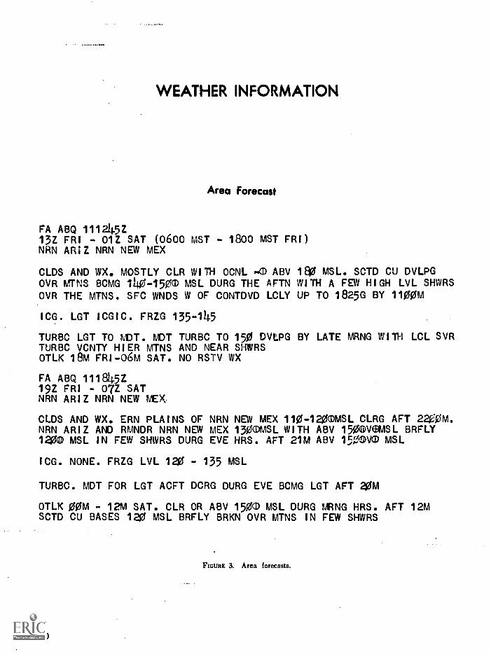
WEATHER INFORMATION
Area Forecast
FA ABQ 111245Z13Z FRI - 01Z SAT (0600 MST - 1800 MST FRI)NAN AR;Z NRN NEW MEX
CLDS AND WX, MOSTLY CLR WITH OCNL ABV 180 MSL, SCTD CU DVLPGOVR MTNS BCMG 140-150T MSL DURG THE AFTN WITH A FEW HIGH LVL SHWRSOVR THE MTNS. SFC WNDS W OF CONTDVD LCLY UP TO 1825G BY 1100M
ICG. LGT ICGIC. FRZG 135-145
TURBO LGT TO MDT. MDT TURBC TO 150 DVLPG BY LATE MRNG WITH LCL SVRTURBC VCNTY HIER MTNS AND NEAR SHWRSOTLK 18M FRI-06M SAT. NO RSTV WX
FA ABQ 111845Z19Z FRI - 07Z SATNRN ARIZ NRN NEW MEX
CLDS AND WX. ERN PLAINS OFNRN ARIZ AND RMNDR NRN NEW1200 MSL IN FEW SHWRS DURG
ICG. NONE. FRZG LVL 120 -
NRN NEW MEX 110-120TMSL CLRG AFT 2200M.MEX 130®MSL WITH ABV 1500VSMSL BRFLYEVE HRS. AFT 21M ABV 1500VIT MSL
135 MSL
TURBC. MDT FOR LGT ACFT DCRG DURG EVE BCMG.LGT AFT aom
OTLK 00M - 12M SAT. CLR OR ABV 1500 MSL DURG MRNG HRS. AFT 12MSCTD CU BASES 120 MSL BRFLY BRKN OVR MTNS IN FEW SHWRS
FIGURE 3. Area forecasts.
30

BEST COPY AVAILABLE
Terminal Forecasts
FT 111045
INW 111123 0. 19Z 90T 2325..PRC 111123 0 2012. 17Z 8001200 2020..FLG 111123 0. 17Z 700)1200 2020..FMN 111123 0. 19Z 90M 2320..ABQ 111123 0. 20Z 100.0 2325..FT 112245
INW 112311 0. 900120T 2525G. 02Z 100T..PRC 112311 0. 800C1200 2320G30. 02Z 01500. 05Z 150-0..FLG 112311 0. 80001200 2020G. 02Z C1200 2325G. 05Z 120-a..FMN 112311 0. C800 2320 OCNLY C7091 BRF RW- VCNTY. 03Z C1000..ABQ 112311 0. 8001200 2020 OCNLY C800 2525G30. 02Z 1000..
FT
ABQFhNPROBLDBCE
3000
1915
10Z -
6000
20201920+1C2715+202816+223018 +24
Winds Aloft Forecasts (FD)
22Z (0300MST - 1500MST)
9000 12000 18000
2325+10 2730+03 2740-102030+10 2040+02 2140-102830+12 2940+05 3040-103032+14 3131+07 3242-123234 +16 3)014+09 31044-1 4
In-Flight Weather Advisories
A kWA -A 111345Z1045M FRIALPHA 1. NRN ARIZ AND W OF CONTDVD IN NWN NEW MEX LGT TOT TURBO BLO 80 MSL WITH STNG DOWNDRAFTS OVER LEE SLPS-A 112320Z= 1900M-FRIALPHA 2. NRN ARIZ NRN NEW MEX MDT TURBC BLO 140 MSL DCRGT BY 1900M
FIGURE 4. Terminal forecasts, winds aloft forecasts, and inflight weather advisories.
31

Pilot Report Summaries
ABQ UB 111245ZGNT - 40 W GNT MDT TURBO 105 BN35. FLG AREA LGT TURBO SEC TO 105PA23. 50 E PRC LGT MDT TURBO 105 PA24. ZUN-INW MDT TURBC 9500 0310ABQ UB 111625ZZUN V-62 SAF MDT TURBO 120 C 182INW - PRC MDT OCNLY SVR TURBO 105 PA22ZUN - GNT MDT TURBO !WIG 9500 C 172
Hourly Sequence Weather Reports07M
SA 111400ZPRC 140-020+0 6115/32/1 810/9 85FLG 120-T15+ 055 55/18/1 812G18/993INW 100060 045/55/26/1810/998ZUN 14020+ 070/,55430/20054995GNT 120-035 gb5/55/31.7000/0 1PHX 9001 20-4:45 075/7 30/270 HK A LQDSTUS E150D300050 060/75/35/1 810/983
Hourly Sequence Weather Reports08M
SA 111500ZPRC 130345 067/68/31/2728/991FLG 120020+ 065/600/20154923INW 100060+ 047/65/31/1 815/909ZUN 1004025 065/60/33/2310/999GNT 1200300-CD35 060465432/1 810G15/000PHX 1000120-035 082/35/33/2705/HK ALQDSTUS E1509300970 075/75/32/2315/985
FIGURE 5. Pilot report summaries and hourly sequence reports.
32

-dr II, 3711,41.-spoihne ankcut 8 i
G % 042ItrjS ea
6Pern l'enci /oft
3ov'er
ize3s2,42.
/... . ......
$0. :8100 441)...z.roes
er4 12*stirtod inne
I Le/reMUCca Silt
ElyA.L....41City
38
Sc40"..
SBois. 53
3tj®1\troca elk,/
43 112
2:11-4°
Lewistown
iscgoi
313
.04341144.6105
Cody
.1\1 4 .....
City
5O%40
................
............al CM
ssmocAbd, Spins.... ........
........
Denve
'as1004
84
if City
56,4043-113
ma
551-r ItieyemL
. Graloft
North-14 WIZ4 4,1
....... .....
4,Goodl d°Stai sr
City
-14 rebel
Bland
6 056love:
................
Winslow
GOE05125
'en""_nwosehoeerix :
2s.<1.1r65i3r4z
Taco _c 35:
I El Paso 2lrteleN0611._ f il,"r31 .1.\
Trinidad015e5r
5/ "43°"olr.........
Gs iloGilbuoueroue
2GfAmarillo .
194-M9
Old.loos
a CityFort
-" ootib4
Abilene
15 :13GS S
land
oft Worthna. *SA
3,C14°-*leo
.4%.
FIGURE 6a. Daily weather map excerpt.
33

IY
SURFACE WEATHER MAPAND STATION WEATHER
AT 7:00 A. M. E. S. T.Wind speed. 121
to 25 miles perhour,)
Direction of wind.(From the north-west.)
Temperature indegrees Fahrenheit.
Thtal amount ofclouds. (Sky coin-plerely covered.)
Visibility. (3/4miles.)
Present weather.Continuous slightsnow in flakes.)
Dewpoint in de-grees Fahrenheit.
Cloud type. (Lowfractostrcitus and /orfractocumulus.)
Height of cloudbase 1300 to 599feet.)
SPECIMENSTATION MODEL
Cloud type(High cirrus)
1'Paz t of sky covered
by lowest cloud.(Seven or eighttenths.)
Abridged from W.M.O. Code
Cloud type. (Mid-.die altocumulus.)
Barometric pres-sure at se4 level. Ini-tial 9 or 10 omitted.(1024.7 millibars.)
Amount of baro-metric change inpast 3 hours. (Intenths of millibars.)
Barometric tend-ency in past 3 hours.(Rising.)
Sign showingwhether pressure ishigher or lower than3 hours ago.
Time precipitationbegan or ended. ( Be-gan 3 to 4 hours ago.)
Weather in past 6hours. (Rain.)
Amount of precipi-tation in last 6 hours.
FIGURE 6b. Daily weather map excerptstation weather.
34

Stan
dard
tim
e zo
neL
ette
rde
sign
ator
Mer
idia
n(d
egre
es)
To
conv
ert
to G
MT
,ad
d(h
ours
)
Atla
ntic
604
Eas
tern
E75
5
Cen
tral
C90
6
Mou
ntai
nM
105
7
Paci
fic
P12
08
Yuk
onY
135
9
Ala
skan
A15
010
Ber
ing
B16
511
I
FIG
UR
E 7
.St
anda
rd ti
me
zone
s an
d co
nver
sion
to G
reen
wic
h (Z
) tim
e.

AIRCRAFT DESCRIPTION
PLACARDS IN THE AIRPLANETHIS AIRPLANE MUST BE OPERATED AS A NORMAL CATE-GORY AIRPLANE. NO ACROBATIC MANEUVERS (INCLUDINGSPINS) APPROVEDIDENTIFICATION: N 2116811.MAXIMUM GEAR OPERATING SPEED: 135 mph, CAS.MANEUVERING SPEED: 130 mph, CAS.MAXIMUM ALLOWABLE WEIGHT IN BAGGAGE COMPART-MENT: 125 lbs.
The following information is excerpted fromthe AIRPLANE FLIGHT MANUAL.
ENGINE OPERATION LIMITATION:Power and Speed 260 bhp at 2625 rpm.
FUEL SYSTEM: The engine is approvedfor 100/130 fuel only. Fuel is suppliedfrom 2 tanks of 32.5 gallons total capacityeach.Separate electric gauges indicate the quan-tity in each tank. The gauges read emptywhen the level is down to 5 gallons sincethe last 5 gallons in each tank are unusable.The airplane is equipped with an elec-trically-driven auxiliary fuel pump forstandby use in the event the engine-drivenpump fails.
OIL: 'rhe, engine uses a wet-sump, full-pressure oil system. The oil capacity is12 quarts.For temperature above 40° F use SAE50; below 40° F use SAE 30.
PROPELLER: The propeller is a single-acting, hydraulic constant-speed type withtwo forged aluminum blades, controlled byan engine-driven governor.
HYDRAULIC SYSTEM: The landinggear and flaps are extended and retractedby hydraulic actuators, powered by an engine-driven hydraulic pump and a pressureaccumulator.
ENGINE INSTRUMENT MARKINGS:Oil Pressure Gauge
Idling 10 psi (red line)Normal Operating Range_ 50-00 pal (green arc)
Maximum PressureManifold Pressure Gauge
Normal Operating Range..
Cylinder Head :TemperatureNormal Operating Range_
Do Not ExceedTachometer
Normal Operating Range_
Maximum (Engine -ratedspeed)
Fuel Quantity IndicatorsLess than one-quarter
tank remaining red arc to red lineEmpty (includes 5 gal-
lons each tank unus-able) E (red line)
EMPTY WEIGHT: 1839 lbs.MAXIMUM GROSS WEIGHT: 2900 lbs.FLIGHT LOAD FACTORS:
Flaps Up +3.8, 1.52Flaps Down +3.5
EMERGENCY PROCEDURES:Emergency Gear Extension Procedure.When the landing gear will not extend
hydraulically, it may be extended Man-ually as follows:(1) Place the gear handle in the full
down position.(2) Pull the auxiliary pump handle
out its full extension.(3) Operate the auxiliary pump handle
up s,nd down until the green gear-down light comes on.
100 psi (red line)
15-24 In, Hg (greenarc)
300-460° F (greenarc)
480° F (red line)
2200-2450 rpm(green arc)
2825 rpm (red line)
FIGURE 8. Aircraft description placard (excerpt fcom Airplane Flight Manual).

1111111 111111111111111111
111911 1111111 :7111111g 111101 1111111 ,..,......
L ...H., mi... :.,.... ,
1111111 ..Ill. rn. ...........,.....: ...Nu 1112111E111111 il DOI '
Plg111 119111111116 -
1 1 .
1 gimmick!. m i: 1
1 1111111111MILIW i '
I - iminamml in - 11"
I - 111111111011111 Ile
1 11111111 :Ilia 1111'' II 111111111111111. 1111:;4
1 11111111 1111111119% 1.A 11111111111111MWe';,
Dila,:
W INN 111 mal LOO NOMMO !
MINIM IMMUNE a4 111111 111
IN % MINIM - I pci
ME& ... if MUN& iims Noss mom. mmi -
I1:
a' . .... ...... w.. I. n INIMMOMI EN 'PR
11.111111111d...11110 IN a 0 , - -
-'11M MM Um m. III *411 - mammon.. - E N - .1s Azpielinnum a - ]
MINI . Nu 7 SWIM IMI NI 01111 - MIME - '411 III 1 wm
um im... .: - um.. . ma 1 ......:1 . um .v. dm 3
p. 10111m001011EN 010ZION11111 a OM
.111 1 3 - ,
MEI IIMEMOMMEEMEMIWZINII E MI MMi10,1 ME MMEM MOMME.
mmomminiminini. 0 smsomm nomid. u u-lit a it u a o sill Iii

WEIGHT AND BALANCE
All airplanes are designed for certain limit loads and balance conditions. These limits foryour aircraft are shown on the graphs for Figure 10.
An individual weight and balance report and equipment list is furnished with each airplane;these documents list the empty weight and empty weight center of gravity of the indi-vidual airplane as equipped when it left the factory. Changes in equipment which affect theempty weight and empty weight center of gravity must be entered in the aircraft mainte-nance records in accordance with Federal Aviation Regulations.
To determine that your gross weight and center of gravity for a given flight are withinlimits, use the following procedure:
(1) From the weight and balance report or the latest entry pertaining to weightand balance in the aircraft maintenance record.
(2) Determine the weights and moments of your disposable load. items, using theloading graph.
(3) Add these items, as shown is the sample problem.
(4) Plot the totals on the center of gravity envelope graph.
EXAMPLE PROBLEM
Example for an airplane with a licensed empty weight of 1839 pounds and a moment of65,873 pound-inches: (Empty weight of-1,839 lbs. multiplied by the number of inches theempty C. G. is from the datumin this airplane 35.82 inches. The figure thus obtained isarbitrarily divided by 1,000, the moment in pound inches.)
We Rh!P01-71I-1A
Moment Ilhsel1000
Empty Weight (licensed) 1839.0 65.9
Oil (12 qts.) 22.5 0.4Pilot and Front Seat Passenger 340.0 12.2
Rear Seat Passengers 340.0 23.8
Full Fuel (55 gal.) 330.0 15.8
Baggage 28.5 2.7
TOTAL 2900.0 120.0
Locate this point (2900 - 120.0) on the center of gravity envelope graph. Since the pointfalls within the envelope the above loading meets all the balance requirements.
FIGURE 11. Weight and balance.
38

1,1111111
14:1
.1,1i .1 14
0141:;
:i"'';'.'.",,il:,.'llit18,ikit,lill,!i11111;11i'i:'il,1111,1'11'"I'illli11'i14:131°:14)1'1'1
11 i .11."..'
.kio,"1, Li ,
..-!:.'01101., .1:11.11,1 ,I,IIv
li, Ill', 1 1
. 11. '1,
1111111,!i11,11,',11;11111'1.111111!!'
I1
111 'ill!I!
IltillitIIIP11,1i1111111,
.1
IIII III11:11 :;1
41LANDING DISTANCE TABLE
GROOSWILL?L.
SSW
1P 11
II
GROUND TO CLEAR GROUND TO CLEAR GROUND TO CLEAR GROUND TO CLEARROLL SR CORTACLI ROLL SO, OBSTACLE ROLL SO' OBSTACLE ROLL SO' OBSTACLE
TS
1190
IWO
1400
NOTE REDUCE LANDING DISTANCES 10% FOR EACH 6 MPH HEADWIND. FLAPS 40 AND POWER OFF.
r ,..trii..:i2L..,..`:,',.:.......,-L..L.,.!.a,..ro ''li
CLIMB DATA ,,,,.,,,i,m;,..r.,r
,,,.
111413111G41015wirosT
Les.
AT IMA LEVEL A WV AT SON FT. II 41.F AT 10000 FT. II AT Iwo rr. a 5 ''I AT 10000 PT. 6 11 F
BESTCLOG
IASMPH
Rasor
CLOGPT/1401
GAL.or
FUEL1.1110
BESTcum
IMIMPH
RATEor
CLIMBPT/1104
FROMR. L.FUELUSED
BUTCLIMB
IASMPH
RATEOF
CLUBFT/M04
mossI. L.FUELUSED
ourCLUB
lasMPH
RATEOF
CLPT/Mo4
FROMS. L.
FUELUSED
BMCLIMB
IMIUPS
RATEOr
mooPT AIM
FROMS. L.
FUELUSED
3300
31100
1100
97
100
104
1770
1010
1300
3.0
3.0
3.0
94
451
101
1415
1100
1010
3.0
3.1
3.3
II
55
WI
MO
VS
720
4.0
4.4
4.6
IM
53
44
715
1110
430
S.1
S.3
6.7
OS
et
54
370
350
140
rS.3
7.11
9.3
LE, 31134:4roprOCAILURI AT RECOMMENDED LEAPING SCHEDULE-FLAPS AND GEAR UP. rum. WED INCLUDESNOTE THROTTLE,
L 1 .,
?
4 7
TAKE-OFF DATA.t
!..:.,..,..,. ...t;
17
OAKS 099 DISIANC1 WITH 20. 11 A55 1ROM IIMIDSUIPACID RUNWAY' 1161,9 OOOOOOOOOOOO W
I'-11
01 41, 1.1,111%14,.,
'lltl 114
1
I
I.I. .. . ,I!, . I It
OOOOOOOA ' 1
' 4
16i
GROSSWEIGHT
LDS.
ISSAT 50 R.
MPH
HEADWINDsum
AT SEA LEVEL ill 511F AT IWO FT. a so. AT 5000 FT. III 41V AT 7500 FT. & ES
GROUNDRUN
TO CLEAR50' OBSTACLE
GROUNDRUN
TO CLEAR50' OBSTACLE
GROUNDRUN
TO CLEAR50' OBSTACLE
GROUNDRUN
TO CLEAR50' OBSTACLE
IR3300
450 3
1530
435265135
695455370
515320170
63524%330
615390315
950650400
,
740460370
i
1145
505.
3500 SS 01530
570350195
455505365
NO435340
1040730445
015530305
1250030.560
. 905. .
655305
ISSIS"1105735 .
2500 6S 01530
740400270
1135710500
600550335
_
A
1355950615
1055705435
1555.1200
715
1365575S40
31551590ION
I1.NOTES INCREASI DISTANCES 10% FOR EACH 35.5' AMYL STANDARD TEMPERATURE FOR PARTICULAR ALTITUDE.
FIGURE 12. Takeoff, climb, and landing distance tables.
39

CRUISE PERFORMANCE 10000
StandardZero Wind
AtmosphereNORMAL
10,000
LEAN MIXTURE
FEET
Gross Weight -55 Gallons
2900 Pounds- No Reserve
RPM MP BHPFuel
Press.MPHTAS
Gal/ 'EnduranceHour Hours
RangeSta. Miles
2450 20 65 7.5 184 12.2 4.5 83019 60 6.8 179 11.4 4.8 86018 58 6.2 174 10.8 5.2 90017 52 5.6 169 9.9 5.6 940
2300 20 59 6.5 177 11.0 5.0 88519 55 6.0 172 10.4 5.3 91018 51 5.5 167 9.7 5.7 95017 47 5.1 162 9.1 6.0 975
2200 20 55 5.9 172 10.3 5.3 91519 51 5.5 168 9.8 5.6 94018 48 5.1 163 9.1 6.0 98517 44 4.8 157 8.6 6.4 1005
2100 20 50 5.3 165 9.5 5.8 95519 47 5.0 161 9.0 6.1 98018 43 4.7 156 8.5 6.5 101017 40 4.4 151 8.0 6.9 103516 37 4.2 145 7.6 7.2 105015 34 4.0 138 7.1 7.8 107014 30 3.8 129 6.6 8.3 1075
FIGURE 13. Cruise performance chart.
40

AIRPORT/FACILITY DIRECTORY
LOCATION
The airport location Is given in nautical miles (to thenearest mile) and direction from center of referencedcity.
ELEVATIONElevation is given In feet above mean sea level and
is based on highest usable portion of the landing area.When elevation is sea level, elevation will be indicatedas "00." When elevation is below sea level, a minussign (-) will precede the figure.
RUNWAYS
The runway surface length, and weight bearing capac-ity are listed for the longest instrument runway orsealane, or the longest active landing Ixtrtion of therunway or strip, given to the nearest hundred feet,using 70 feet as the division point, i.e., 1468 feet wouldbe shown as "14"; 1474 feet would be shown as "15".Runway lengths prefixed by the letter "II" indicatesthat runways are hard surfaced (concrete; asphalt;bitumen, or macadam with a seal coat). If the run-way length is not prefixed, the surface is sod, clay,etc. The total number of runways available is shownin parenthesis. (However, only hard surfaced run-ways are counted at airfields with both hard surfacedand sod runways.)
RUNWAY WEIGHT BEARING CAPACITYRunway strength data shown in this publication is
derived from available information and is a realisticestimate of capability at an average level of activity.It is not intended as a maximum allowable weight or asan operating limitation. Many airport pavements arecapable of supporting limited operations with grossweights of 25-50% in excess of the published figures.Permissible operating weights, insofar as runwaystrengths are concerned, are a matter of agreementbetween the owner' and user. When desiring to operateinto any airport at weights in excess of those publishedin this publication, users should contact the airportmanagement for permission.
Add 000 to figure following S, D, DT and MAX forgross weight capacity, e.g., (S-000).
S-Runway weight bearing capacity for aircraft withsingle-wheel type landing gear. (DC-3), etc.
D-Runway weight bearing capacity for aircraft withtwin-wheel type landing gear. (1)0 -6), etc.
DT-Runway weight bearing capacity for aircraft withtwin-tandem type landing gear. (707), etc.
Quadricycle and twin-tandem are considered virtuallyequal for runway weight bearing considerations, as aresingle-tandem and twin-wheel.
Omission of weight bearing capacity indicates infor-mation unknown. Footnote remarks are used, to indicatea runway with a weight bearing greater than the longestrunway.
LIGHTINGII: Rotating Beacon. Green and white, split-beam and
other types.Field Lighting. An asterisk (0) may precede an ele-
ment to indicate that it operates on prior request only(by phone call).
4Low Intensity Runway5Medium Intensity Runway6High Intensity Runway7--Instrument Approach (neon)7AMedium Intensity Approach Lights (MALS)0High Intensity Instrument Approach (ALS)
10Visual Approach Slope Indicator (VAS')11Runway end identifier lights (threshold
strobe) .(REII.)12Short approach light systems (SALS)13Runway alignment lights (RAIL)14Itunwny centerline15Tonchdown zone
Because the obstructions on virtually nil lighted fieldsare lighted, obstruction lights have not been included Inthe codification.
SERVICING52: Minor airframe repairs.S3: Minor airframe and minor powerplant repairs.54: Major airframe and minor powerplant repairs:S5: Major airframe anti major powerplant repairs.
(Fuel data includes each grade available.)Code GradeF12 80/87F15 91/98F111 100/130F22 115/145F30 Kerosene, freeze point -40°FF34 Kerosene, freeze point -58°FF40 Wide-cut gasoline, freeze point -60°FF45 Wide-cut gasoline without icing inhibitor, freeze
point -60°F
OXYGENOxl High Pressure13x2 Low Pressure0x3 High PressureReplacement Bottles0x4 Low PressureReplacement Bottles
FIGURE 14. Airport/facility directory.
41

OTHERtNOTA111 Service is provided. Applicable only to
airports with established instrument approach pro-cedures, or high volume VFR activity.
a0IAirport of EntryA customs Airport of Entrywhere permission from U.S. Customs is not re-quired, however, at least one hour advance noticeof arrival must be furnished.
F5SThe name of the associated FSS is shown in allinstances. When the FSS Is located on the named air-port, "on lid" is shown following the FSS name.When the FSS can be called through the local tele-phone exchange, (Foreign Exchange) at the cost ofa local call, it is indicated by "(LC)" (local call)with the phone number immediately following thename of the FSS, i.e., "FSS: WICHITA (LC481-5867).." When an Interphone line exists between thefield and the FSS, it Is indicated by "(DL)" (directline) immediately following the name of the PBS,i.e., "FSS: OTTO (DL)."
IFRAirport with approved FAA Standard InstrumentApproach Procedure.
ERALanding Rights AirportApplication for permis-sion to hind must be submitted in advance toU.S. Customs. At least one hour advance noticeof arrival must also be furnished.
TCHThreshold Crossing Height.RRPRunway Reference Point.RvVRunway Visibility Values, applicable runway pro-
vided.RVItRunway Visual Range, applicable runway provided.TraTraffic Pattern Altitude.VASIVisuat Approach Slope Indicator, applicable run-
way provided.
AIRPORT REMARKS"FEE" indicates landing charges for private or non-
revenue producing aircraft. In addition, fees may becharged for planes that remain over a couple of hoursand buy no services, or at major airline terminals forall aircraft.
"kit tic 13-31" indicates right turns should be madeon landings and takeoffs on runways 13 and 31.
Remarks data are confined to operational items affect-ing the status and usability of the airport, trafficpatterns and departure procedures.
Obstructions.Beettuse of space limitations only themore dangerous obstructions are indicated. Naturalobstructions, such as trees, clearly discernible for con-tact operations, are frequently omitted. On the otherhand, all pole lines within at least 15:1 glide angle areindicated.
FLIGHT SERVICE STATIONSFlight Service Station (FSSs) and Combined Station/
Tower (CS/Ts) are listed alphabetically by state Inthe Airport/Facility Directory. At certain locations thepreflight briefing and flight plan processing responsi-bilities of the CS/T have been reassigned to an adjacentFSS. At these locations the adjacent FSS will be listedas the 'Associated FSS,' otnerwise, the CS/T will belisted. Limited Rembte Communications Outlet (LIICO)and Remote Communications Outlet (RCO), where
42
available at the facility, are shown following the threeletter identifier. If located at other than a facility sitethey are listed alphabetically.
FSSs and CS/Ts provide information on airport con-ditions, radio aids and other facilities, and process flightplans. Airport Advisory Service is provided at thepilot's request on 123.6 by FSSs located at non-towerairports or when the tower is not In operation. (SeePart 1, ADVISORIES AT NON TOWER AIRPORTS.)
Aviation weather briefing service is provided by FSSsand CS/Ts; however, CS/T personnel are not certifiedweather briefers and therefore provide only factual datafrom weather reports and forecasts. Flight and weatherbriefing services are also available by calling the tele-phone numbers listed in the chapter entitled 'FSS-CS/TInformation and Weather Service Office Telephone Num-bers,' located in Part 2."
Civil communication frequencies used In the flight service sta-tion air/ground system are now operated simplex on 122.0,122.2, 122.3, 122.6, 123.6 and emergency 121.5 plus 122.1and 123.6 receive only as follows:
a. 122.0 is assigned at selected FSS, as a weather channelfor both general aviation and air carriers.
b. 123.6 is designated as an airport advisory channel at allFSS5 which provide this service at nontower locations. 123.6 isstill in commission at some FSSs collocated with towers fey thepurpose of providing part-time Airport Advisory Service.
c. Some FSS', use 123.65 or certain 50 KHz channels In the122-123 MHz band (such as 122.05). Pilots using the FSSA(G system should Met to this directory or appropriate shortsto determine frequencies available at the FSS or remelted facilitythrough which they wish to communicate.
Part time FSS hours of operation are shown in re-marks under facility name.
COMMUNICATIONSClearance is required prior to taxiing on a runway,
taking off, or landing at a tower controlled airport.When operating at an airport where the control tower
is operated by the U.S. Government, two-way radiocommunication is required unless otherwise authorisedby the tower. (When the tower is operated by someoneother than the U.S. Government, two-way radio com-munication is required if the aircraft has the necessaryequipment. )
Frequencies transmit and receive unless specified as:TTransmit only, RReceive only, XOn request.Primary frequencies are listed first in each frequency grouping,i.e., VHF, LF. Emergency frequency 121.5 is available atall TOWER, APPROACH CONTROL and RADAR fa-cilities, unless indicated as not available in remarks.
Radar available is listed under "RADAR SERVICES"Radar beacons are indicated by "(ECN)" after "RADARSERVICES", when available.
COMMUNICATIONS REMARKSRemarks data are confined to operational items affect-
ing the status and usability of navigational aids, suchas ILS component restrictions, part time hours of op-eration, frequency sectorization, VOT frequencies.
FIGURE 15. Airport/facility directory.

AIRPORT/FACILITY DIRECTORY
VOICE CALLThe voice call for contact with the air traffic control
Identification of VOR/VORTAC/TACAN Stations by Class (Oper-ational Limitations):
SERVICES AVAILABLE
RADIO CLASS DESIGNATIONS
TOWER
Pre-Taxi Clearance ProcedureClearance Delivery (CLRNC DEL).Approach Control (App Con) Radar and Non-Radar.Departure Control (Dep Con) Radar and Non-Radar.NTR Advisory Service (VFR ADV) Service provided
by Non Radar Approach Control.Radar Advisory Service for VFR Acft (Stage I).Radar Advisory and Sequencing Service for VFR
Acft (Stage II).Radar Sequencing and Separation Service for VFR
Acft (TCA).Ground Control (GND CON).VHF Direction Finding (VHF/DF),
RADIO NAVIGATION AIDS
Included In this section is a tabulation of all Air Navi-gation Radio Aids in the National Airspace Systemand those upon which the FAA has approved anInstrument approach. Private or military Naviga-tion Radio Aids not in the National Airspace Systemare not tabulated.
AUTOMATIC TERMINAL INFORMATION SERVICE (ATIS)
ATIS is continuous broadcast of recorded non-controlinformation in selected areas of high activity. SeePart 1.
FLIGHT SERVICE STATION IFSS)
Airport Advisory Service (AAS).Island. Mountain and Lake Reporting Service.Remote Weather Radar Display (WR).VHF Direction Finding (DF).
UNICOM
A private aeronautical advisory communications facil-ity operated for purposes other than air traffic control,transmits and receives on one of the following fre-quencies:
U-1--122.8 MHz for Landing Areas (except heli-ports) w'thout an ATC Tower or FSS;
U-2-123.0 MHz for Landing Areas (except heliportswith an ATC Tower or FSS;
U-3-123.05 MHz for heliports with or without ATCTower or FSS ;
U-4---122.85 MHz for landing areas not open to thepublic;
U-5-122.95 MHz for landing areas not open to thepublic.
NOTE.UNICOM used for communications must be li-censed by the Federal Communication Commission in orderto be listed in this publication.
ClassTLHH
Normal Usable Altitudes and Radius DistancesDistance
Altitudes (miles)
12,000' and below 25Below 18,000' 40Below 18,000' 4014,500' 17,999' 100*18,000' FL 450 130Above FL 450 100
*Applkable only within the contiguous 48 States.H=High L=LoW T=Terminal
Nom: An H facility is capable of providing L and Tservice volume and an L facility additionally provide. T
service volume.
The term VOR is, operationally, a general term cover-ing the VHF omnidirectional bearing type of facilitywithout regard to the fact that the power, the frequency-protected service volume, the equipment configuration,and operational requirements may vary between facilitiesat different locations.
Automatic Weather Broadcast (alsoshown with following frequency).
B Scheduled Broadcast Station (broadcastsweather at 15 minutes after the hour.
UHF standard (TACAN compatible) dis-tance measuring equipment.
H Non-directional radio beacon (homing),power 50 watts to less than 2,000 watts.
HH Non-directional radio beacon (homing),power 2,000 watts or more.
Non-directional radio beacons providingautomatic transcribed weather service.
ILS Instrument Landing System (voice, whereavailable, on localizer channel).
LMM Compass locator station when installed atmiddle marker site.
LOM Compass locator station when installed atouter marker site.
MII Non-directional radio beacon (homing)power less than 50 watts.
SABH Non-directional radio beacon having lim-ited navigational use. Provides auto-matic weather broadcasts.
SDF Simplified Direction FacilityTACAN UHF navigational facilityomnidirection-
al course and distance information.VOR VHF navigational facilityomnidirection-
al, course only.VOR/DME Collocated VOR navigational facility and
UHF standard distance measuringequipment.
VORTAC Collocated VOR and TACAN naviga-tional facilities.
Tp Without voice on radio facility fre-quency.
VHF station location marker at a LFradio facility.
AB
DME
HSAB
FIGURE 16. Airport/facility directory.
43

Longest RunwaySurface and length
NOTAM ServiceProvided
AirportElevation
AIRPORT/FACILITY DIRECTORY
SAMPLE
Location(NM from City)
No. ofRunways
LongestRunwayBearing
Location-r Identifier
IFR Airport
Runway WeightBearing Capacity
Airportof Entry
AssociatedFlight Service Station
Y PlAhl
NAME // Lighting
CIT
STATE
I
Local PhoneNumber
Servicing
Fuel
1 AIRPORT HMI IFR 3.4ENE AOE PSS: NAME (LC 4111 5867)
5331 H55/8-26(31 I5-100, D -200, DT-400) 816,11,10,11) Si F12,18,30 Oxl Runway
gen
uNICOM 15-2 VASI: Rnwy 13 NEIL: Inwy 26 IVV: Visibility ValueIVO: Inwy 36
Runway .,,.....--ensarks: Fee: $1.50 ocft over 4,000 lbs. No turns until reaching Runway End Identifier Lights
Visual Range 6000' MSL. Clsd to fighter type jets excp on prior request.Tower 118.1 122.51 278T Gnd Con 121.9
$Clmc Del 127.7
ATIS: ARR 112.7 DEP 124.2
Radar Services (SCN)App Con 119.5' 125.62
Den Con 126.2Stag* 1 Ctc APP CON 25 mi out on 125.6
VFR Advisory Ctc Ng on 119.1ILS 109.9 I-MGM Apch Brg 093° BC unusable(HI 1VORTAC 115.6/PHP /122.11 122.T 256° 5.3yaggi H-gAg 326' /PH 264° 1.5 NM to Fid.VHF /DP Ctc twr/FSSRemarks: '127 °-307° 23089-126° LOM is H-SAB.
ALL BEARINGS/RADIAL ARE MAGNETIC.
PreTaxi ClearanceProcedure Avail.
Automatic TerminalInformation Service.
Radio Aids
Transcribed WeatherBroadcasts (TWO)
44
LOM 326/PHNM to Rd.
LECO or KOVON
VOT: 108.2.
APPROACH CONTROL SECTORS
FIGURE 17. Airport/facility directory.
Test Signal

AIRPORT/FACILITY DIRECTORY
ARIZONA
BUCKEYE IL/ BVORTAC 110,6/BXK/ 122.1R FM PHOENIX PRESCOTT Fff 121.5 122.1R 122.2 122.6 123.6
CASA GRANDE 111 IVORTAC 114.8 /CZG /122.1R FSS: PHOENIX Remarks: No weo bcst ovbl 2200-0400 Icl lime,
COCHIN IL/ BVORTAC 110.4/CIE/122.1R FSS: DOUGLAS
DOUGLAS FSS 121.5 122.1R 122.3 122.6 125.6
Remarks: No weo bctt ovbl 2200-0500 Id lime,DOUGLAS IL) BVORTAC 108.8/DUG FM: DOUGLAS
FLAGSTAFF IL/ IVOR 108.2/FLG/122.3R FSS: PRESCOTT
GILA BEND MI IVORTAC 116.6/G11N/121.5 122.1R 122.6FSS: PHOENIX
GLOBE LRCO 122.3
GOODYEAR1 PHOENIXLITCHFIELD MUNI IGYR/ 1SW
OF
PRESCOTT (H) BVORTAC 114.1/PRC FM PRESCOTT
RYAN NDB H-SAB 338 /RYN FSS: TUCSON
ST. JOHNS (HI IVORTAC 112.3/SIN/122.1R FSS: ZUNI
SAN SIMON IHI IVORTAC 115.4/SSO/122.1R 'FM DOUGLAS
TUBA CITY (H) IVORTAC 113.5/T8C/122.2R FM PRESCOTT
TUCSON LIMO 122.2 FSS: TUCSONFSS: PHOENIX
TUCSON FSS 121.5 122.1R 122.2. 122.6 123.65
FM PHOENIX(LC 261-4295)
968 H8513-21(11 (5-60, D-80, 01-140) 8L6 S5 F12,18,22,30
RORICIF1111: Rgt tfc rnwy 3. Rnwy 21 thr dsplcd 2000'.Litchfield Tower' 120.1 122.7R
Radar Servkes:App Con 120.7
VFR Advisory Ctc App ConRemarks: 'Open 0600-2200 1cl time. Twowoy rdo required.
GRAND CANYON Ill BVOR 109.0/ GCN/ 122.1 R FSS: PRESCOTT
IMPERIAL LICO 122.0
KINGMAN IL/ IVOR 108.8/IGM/122.2R
MAUI NOB t4W 266/MOI
FSS: IMPERIAL
FSS: PRESCOTT
FSS: PRESCOTT
NOGALES ICO 122.2
PAPAGO NOB H-SAB 326M/POO
FSS: TUCSON
FSS: PHOENIX
PEACH SPRINGS 1141 IVORTAC 112.0/PGS/122.3R FSS: PRESCOTT
PHOENIX FSS 121.5 122.1R 122.3 122.6 122.05 DF
Remarks: No weo bat ovbl 2200-0600 Icl lime,
PHOENIXDEER VALLEY IP09) 17N FSS: PHOENIX
1475 H51/7-25(1) (5-30, D-45, DT-60) 1314 S5 F12,18 UlRemarks: 5150 x 60 extension E end clsd, but ovbl on, prior
request. Glider operns in vicinity of orpt Sot & Sun 1100 -Sunset.
Deer Valley Tower' 118.4 God Con 121.8
Remarks: 'Opera 1000-1800 Icl MonFri, downdusk Sot ondSun. Non.fed ATCT owned ond operd by City of Phoenix.
PHOENIXSKY HARBOR INTL (PHX( IFR 3E LRA FSS: PHOENIX on Fld1128 H103/13R-261(2) (S-100, D-200, DT-350) 815,7A,10,11,13 S5F12,18,22,30 Ox1,2,3,4 U2 VAS!: Rnwy 8R REIL: Rnwy BL, 26RRVV: Rnwy 8R.Remarks: Rgt tfc rnwys 8R, 26R. Rnwy 261 thr:shold disploced
700'. VASI rwy 8R TCH 46', RRP 1010'. Unless odzd by ATColl turbine ocft ond ocft 12,500 lbs ond over remain at orobove 3,000' MSL until estobd on Ono'. Fly bose leg ofleost 5 mi fm arpt.
Phoenix Tower 118.7 (Rnwy 81-26R) 120.9 (Rnwy 8R-26L) 122.5R
* Clmc Del 118.1
ATIS: 125.6Radar Services: (BCN)
Phoenix App Con(270-009°), 115.61
Phoenix Dip Con(270 - 009 °), 115.61
Stage I Ctc App Con beyond 10 milesPhoenix IHI IVORTAC' 115.6/PHX 256° 5.3 NM to fld.Remarks: 'No weo bcst ovbl 2200-0600 Icl time. VOT: 109.0,
Gnd Con 121.9
119.2 (010-1091, 124.1 (110-269°1, 120.7
122.5R
119.2 (010- 109 °), 124.1 (110- 269 °), 120.7
122.5R
CIF
I TUCSON INTL ITUSI IFR 7S AOE FSS: TUCSON on Fld2630 H120112L-301113) (S -120, 0-160, DT-260) BL5,10 SSF12,18,22,30,40 Ox1,2,3,4 U2 VASI: Rwy 301Remarks: 1000' x 150' osph overrun eoch end rnwy 12L-30R.
Lndg fee. Jbor rwy 121 -30R. VASI rwy 30R upper TCH 78',lower TCH 42'; upper RRP 1690', lower RRP 1090
Tucson Tower: 118.3 122.5R Gnd Con 121.9
Radar Services: (BCN)App Con 118.5 125.1 125.9 134.1 117.11Dip Con 125.9Stage II Clc App Con on 124.0 25 NM out
VHF/De Ctc FSS.OD IVORTAC 117.1/TUS 254° 6,1 NM to lid14111110AS: Unusoble beyond 40 NM below 13,500' MSL 345-070°
below 12,500' MSL 070-090°.WINSLOW IHI BVORTAC 112.6/INW/122.1R 122.6
FSS: PRESCOTT
YUMA FSS 121.5 122.1R 122.2 122.6 123.6
Remarks: No sked weo bcst 2200-0500 Icl lime.1 YUMA MCAS/INTI. (YUM1 IFR 45 AOE F55: YUMA on Fld
213 H133/31-21R(4) (S-103, D-200, DT -400) BL6 S5 F12,18,30 U2Remarks: Rnwy 3R-21L GWT (S-162, 1-200, 11-400). 1000 x 200'
overrun eoch end rnwy 31 -21 R. Ageor rnwys 3L-21R ond3R-211 2200-0600 civil rnwy will remain Igtd ond oddnl Igtgovbl thru FSS in emerg.
Marine Yuma Tower' 119.3 126.2 Gnd Con 121.9App Con 120.0VHF /DF CleIHI IVORTAC 116.8/YUM 167° 6.0NM to fld.NDB MHW 344/NYL on fld.Remarks: 'Operotes 0600-2200 Icl time except ovbl for emgcy.
Ctc FSS for oirport odvisory service when tower closed.
FIGURE 18. Airport/facility dircctory.
45

.AIRPORT DIRECTORY
ARIZONA
AN, MUNI (P01) IN 32'27'00" 11212T0" FSS: PHOENIX
1458 1163/12.30 111 LI 112
REMARKS: ARPT UNATTENDED. NTT JET TIC VCNTY ARM, FUEL AVBL EMERG, CALL
SWF, 3874621. LGTS ON CENTER 3950 FT.
ANGEL RO Si. IMF SIAM
ANTELOPE RANCH Si. ROLL
*51 1011 IN 35'13'55" 112'29'10" FSS : PRESCOTT
5169 34/7.25 (3)
REMAINS: ARPT UNATTENDED PLNIE IN ANY 1 VON. VLF( IN RWY 25 APCH.
2NE 3414'45" 113'10'10" FSS; PRESCOTT
4136 113615.23 (I) (S4) BL4
RIMAIKS: ARPT UNATTENDED. UNUSUAL AIR CURRENTS VICINITY ARPT,ESPECIALLY
EAST APCII. NWT LGTS ACTIVATED BY KEYING 122.8 3 TIMES OR BY PRIOR REO OR
CIRCLING TOWN.
SISIEE, MUNI (PO4) 6SE 3111'50" 109'52'51" FSS: DOUGLAS
4780 39/2.20 (3) LI FI2REMARKS: PLINE IN RWY 2 APCH. PLINE IN RWY 8 APON. RIMY LGTS ACTIVATED ON
122.8.
CLIFTINIIIMENCL GREENLEE COUNTY (CFI) 9SE FSS: DOUGLAS
3r57'10" 10r12'35"3111 N49/7.25 (I) 21) 'BLSREMARKS: AIPT UNATTENDED. FOR am' LGTS & ROTC ICN PHONE 864.3080 OR
864.4149.
COMM COUNTY See IPLCII
COLUMN COY, MUNI 451 36'56'58" 1131010" FSS: CEOAR CITY
4640 34/1311 (2) FI2REMARKS ARPT UNATTENDED. FUEL IN EllIERG ONLY.
CISUIME, NUN) 2SW 32'53'00" 11112'45" FSS: PHOENIX
1402 N21/8-26 (I) (54) 112 1LC 723.3392)
111111115: ARPT ATTENDED DAYLIGHT. FUEL IN (VERO ONO.
CUUNE, FLORENCE MUNI (P08) 6SE 32'56'00" FSS: PHOENIX
11115'30"1587 N55/5-23 (4) 1510,0115,011210) SS 112. 18 U.) (LC 123.3392)
REMAILS: RGT TFC MK S. 11. I 1.35. TRAFFIC PATTERN ALTITUDE 1000FT AGL.
PARACHUTE JUMPING SAT & SUN. ALL TFC PENS VARY DORM Pi TRIUNING.
S emus BISBEE, BISBEE DOUGLAS INTERNATIONAL (DUG) FSS: DOUGLAS ON FLO
9NVI 31'28'04" 109°36'11" OR ADE
4158H15/12.30 (4) (S12) BLS SS F12, 18, 22.30REMARKS: RWY 8.26 WI BRG CPTY S85.0.95,0E155. RWY LGTS OPER ON REO THRU
OUG FSS.
DOWNTOWN TUCSON See TUCSON
OVR SOS TACNA
EOS FIELD Si, PICACNO
(LOT, MUNI UST 32°48'25" 111°35'10" 'SS: PHOENIX
15131139/2.20 (1) (5.12.5) BLS SS F:2. 18
ESTRELLA SAILPORT Set NARICIPA
EUREKA RANCH See BONITA
FALCON FLO See MESA
FARM AERO Ste P11111111
S FLAGSTAFF, PULLIAM (FLG) SS 3518'16" 111°40'18" 155: PRESCOTT
IFR
1012N10/3.21 (I) (S65.0.85.0T130) 015 SS F12, 18 (LC 114.04151
1111
REMARKS: ARPT ATTENDED 0700.2000. ARPT ATNOD ON CALL OTHER HRS.
FOREPAWS Si VICKSBURG
FOREST ACRES Set SELIGNIMI
46
GREEN VALLEY Set MINT
GREENLEE COUNTY Si. CLIFT011111011ENCI
HEREFORD Set NICISINUE/NEREFORI/
IMUNINI, MUNI (P14) 3NE 3416'20" 110'08'20" FM ZUNI
52451450/3.21 (1)15.12) BLS 53 112, 18
UNIANKS: P.LNIC NI RWY 29 APCII,
1911111, SIT HANNON INTL (MX) 3E 33°2617" IFSS: PHOEINK ON FLO
112'0013" WI1128 11103/111146L (2) (S100,0400,111150) BLS. 711, 10, 11
55 112, 18, 22, 30 011,2,3,1 U2VAS1: NWT MN NEIL NWT IL, 2611 III: NW IR
REMARIS: (t) NWT 2K THRESHOLD DISPLACED 100'. ROT TIC NWT 26R, OR.
UNLESS ACID BY ATC AU TURBINE AM AND ACTT 12,500 LDS AND OVER REMAIN
AT ON ABOVE 3000 FT MSL UNTIL EMIR ON FINAL. FLY BASE LEG AL LEAST 5 MI
FM ART.PINACCA 4511 3541'00" 110r25.00" FSS: PRESCOTT
5573 38/NESW (2)
REMARKS: ARPT UNATTENDED. RGT TIC NWT NE; SW, NW, SE.
S MEMOIR. NUN (PRO . IN 3419'05" 112.25.15" IFR PRESCOTT ON FLO502 1476/3.21 121 (540,040,01.100) 815 SS F12, 14, 30
U.2
1111111: CTC FSS
RWY 3 THRESHOLD DISPLACED 191',
PUU.LIM LN PLAISTUF
TUCSII, DOWNTOWN TUCSON AD) SE 32'11'10" Fit: TUCSON110°56'55"
2490 43/16.34 (2) SS 112 (LC 7924359)REMARKS: ARPT ATTENDED OAWNOUSK. PINE N NWT II RPM. PINK IN MK 29
APCH. PM( IN RWY 16 APCH.
9 TUCSON, FREEWAY (P12) INN 32°16.40" 11110'30" FSS: TUCSON
2290 1145/12.30 111 IS.6) 8L4 SS F12, 18 UI (LC 192.6359)
REMARKS: NWT 30 THRESHOLD DISPLACED 300'. PINE NI RIVE SO APCII.
TUCSON, RYAN FIELD I2SW 32°08'29" 11110110" FSS: TUCSON
2413 H40/6R24L (I) (S.9) 8L4 55 F12. 18 (LC 7924359)REMARKS: ARPT ATTENDED 0700.1700. ROT TIC NWT 611. 16. RIMY 61/2411
RESTRICTED TO GLIDERS ONLY. 2525 X 25 FT ASV saw SUPERIMPOSED ON DIRT
STRIP 6L/24R BEGINNING 625 FT FROM SOUTH END.
S TUCSON. INTL (TUS) 7S 32°01'OS" 110'56'32" FR FSS: TUCSON ON FLO
AOE
2630 H120/12130R 13) (S120.0.160,011260) BLS. 10 SSF12, 18. 22. 30.40 0XI.2.3.4 U.2
VASI: RWY 30R
WIF/IF: CTC FSSREMARKS: (t) ARRESTING DEVICE RWY 21. 12L. 301. 1000 it ISO ASPII OVERRUN
EACH END RNWY 12L30R.
WILLIAMS, MUNI (P32) IN 35°18'08" 112°12'00"61001139/2.20 (1) (S17) 814 SS F12, 18 UIUNARMS: UPI ATTENDED 0800.1700.
WINDOW ROCK (P34) IS 35°39'20" 109°03'45"61551110 /2.20 (1) (S30.045,0E75) LS F18
'ISAIAS: ARPT ATTENDED 0800.1100.
9 WINSLOW, MUNI IINIT) IW 35°01'20" 110'43'20" FR FU: PRESCOTT4938 N75/11.29 (2) 1S.35,D.55) 815 S3 F12. 18 U.) (OL)
REMARKS: RWY 4.22 WE BRG CPTY S.50,0.70. ARPT ATTENDED 0700.1800.
ATTENDANT ON CALL FOR FUEL AFTER 1800 UNTIL 0700 WITH NO CHARGE.
MINA, MCAS/YUMA INTERNATIONAL (YOM) IS 32°39'21" fSS: YUMA ON FLO114°36'18" IFR AOE
2)3 H133/3121R IS103.0.200.01.400) OLD SS F12,18, 30
CTC IllREMARKS: (t) RWY 3R2IL WT BRG CPTY S162.0.200.0T100 1000 X 200
OVERRUN EACH END RNWY 31.21R. FSS WILL PROVIDE ARPT ADV SVC WHEN EFS
IS CLSO. 22000600 APROP CIVIL RNWY WILL REMAIN LGTO A AOONL LOG AVBLTHRU FSS IN OAERG.
FSS: PRESCOTT
FSS: ZUNI
FIGURE 19. Airport /facility directory.

NOTICES TO AIRMEN
This part is issued every 2B days. It contains appropriate notices from the daily NOTAM Sum-mary, and other items considered essential to flight safety. See Part 3A for additional data.
This section contains Notices to Almon that are expected toremain in effect for at least seven days. Temporary noticeswithout published durat:on dotes are normally carried twice un-less resubmitted.
NOTE: Data preceded -by a theckmark 141 are considered per-manent and will be publishes' one time only In this section.Dale should be noted on charts and records.NOTE: Net:ces are arranged In alphabetical order by State landwithin the State by qty or locality).
NEW OR REVISED DATA: New or revised data are indicated byunderlining the Rnt line of the affected Item. The new IntimationIs net necessarily limited to the underlined portion, which Is usedonly te attract attention te the new Insert.
ALABAMA
ANNISTON, ANNISTON-CALHOUN ARPT: Smallarms firing ranges 6 NM from "ANB" NDB between015-040° up to 2500' MSL, operates continuous. 1094'obatn 1.3 mi SE of arpt unlgtd. Rwy 5 ILS/LOCBC unusable UFN. Rwy lgts first 3500' and thr lgtsrwy 5 OTS UFN. (9-71)
DOTHAN ARPT: Rwy 31 ILS/OM OTS UFN. (10-71)GADSDEN RDO: *OR "GAD" has unusable sectors, for
current information see Substitute Routes.MOBILE, MOBILE AEROSPACE ARPT: Rwy 14-32
apch lgts not operg. (12-71)REDSTONE RDO: TVOR "HUA" OTS UFN. (1-72)TALLASSEE MUM ARPT: A mobile ATCT will
be operd by Alabama ANG from 1000-1500 Id on thefollowing dates: Mar 11, 12, 18, 19; Apr 8, 9, 15, 16;May 13, 14, 20, 21; June 10, 11, 17 and 18. Civil acftctc Tallassee twr freq 126.2 for adzy info prior toentering tic area." (2-72)
TUSCALOOSA, VAN DzGRAAF ARPT: ILS rwy 4ident TCL comsng delayed until aprxly Mar 31, 1972.
ALASKASPECIAL NOTICE: Pilots flying aircraft equipped with
SCR-718 altimeters will assure that the altimeter isturned of within 200 NM of Clear, Alaska and Thule,Greenlat.d.
For complete information on Alaska consult the AlaskaSupplement.
ARIZONACOCHISE RDO: VORTAC "CIE" to be shutdown eff
6 Mar til on or about 10 Mar for freq change from110.4 to 115.8. (2-72)
GRAND CANYON NATIONAL PARK : All pilots arerequested to avoid flying below the canyon rim andto maintain a distance 1500' above and horizontallyfrom all scenic overlooks, parks, trails and GrandCanyon Village.
MARICOPA : CAUTIONDO NOT MISTAKE FORLANDING AREA. Space Surveillance Stu at 1st33°06'31", long 112°01'46" aprxly 4 ml N. 1200' W andparallel to hwy. Site is strip 300' x 1800' with pavedportion lengthwise thru cntr 100' in width and studdedwith 6' steel posts. This permanent hazard lctd 22 nmiS Phoenix-Sky Harbor Intl Arpt.
MT. HOPKINS SPECIAL NOTICE: Controlled firingarea for Laser Operations is established at the Mt.Hopkins Observatory located at 31°40'52"N, 110.52' -41"W. Firing area includes the airspace from 7600'MSL to unlimited altitudes within a circular areawith a one nautical mile radius extending outwardand upward in a conical shape from the radius basedon an angle of 25° above the horizon. All acft shouldavoid this area. Contact Tucson FSS for hours ofoperations.
WILLCOX, COCHISE COUNTY ARPT: Rwy lgts loopand rwy 3-21 clad UFN due resurfacing. (1-72)
YUMA, YUMA MCAS/YUMA INTL ARPT: Rwy 3L-21Rclad UFN. (1-72)
ARKANSASHOT SPRINGS, MEML FLD ARPT: Rnwy 13-31 chid
UFN. (10-71)
CALIFORNIASPECIAL NOTICE: Do not mistake dirt strip on large
island, Lake 13erryessa, lctd lat 38-34 long 122-13 forairport. Strip is unauthorized and unsafe.
ANO NUEVO ISLAND: Avoid low flying in the vicinityand over island. Biological research of wild life inprogress.
BLYTHE ARPT: Intensive airline jet acft training inprogress 24 hrs daily. Inbound acft report 20 milesout on 123.6 and guard 123.6 for arpt advisory service,UFN. Use other frogs for other purposes. Unicorn isnot for arpt advisory use.
BURBANK, HOLLYWOOD-BURBANK ARPT : Highrear mounted engine acft such as B-727, DC-9,shall not apply tkof thrust prior to threshold rwys25 and 33. For these acft the usable length of rwy25 for tkof is 5804'/for rwy 33, 6554'.
CAMBRIA, RANCHO SAN SIMEON ARPT: Clad UFN.(7-71)
CARLSBAD, PALOMAR ARPT: Power lines twr totwr located 2 miles SW and W up to 650' MSL. (8-71)
Rime 20. Notices to Airmen.
47

THE AIRSPACE
VFR ALTITUDES/FLIGHT LEVELSCONTROLLED AND UNCONTROLLED AIRSPACE
UNDER VFR-More than 3,000'COURSES ARE MAGNETICabove the surface.
.E
Below 18,000 feet
0
EVEN
Thousandsplus 300 feet
4,500; 6,500;8,500; etc.)
ODD
Thousandsplus 500 feet(3,500; 5,3007,500; etc.)
.9.
Above 18,000 feet tA51 toFlight Level 290 (inclusive)
EVEN
.1 Flight Levelsplus 500 feet
(1SS, 205.225, etc.)
ODD
Flight Levelsplus 500 fie
(193, 215,235, etc.)
180
IFR ALTITUDES /FLIGHT LEVELSUNCONTROLLED AIRSPACE
A
48
Outside Controlled Airspace.
Below 18,000 feet
0
EVEN
Thousands
s .
COMMIS A= MAGNETICAt or mew 18,000 feet MRbut below Right Level 290
EVEN
Thousands S Flight Levels
2,000; 4,000; 3,000;5,008; i I (180, 200,6,000; etc.) 7,000; etc.) 220, etc.)
90 t s4-
.0. 'gip,
t
Above Flight Level 290
0
4000 footintervals beginning at
Ft 320
(flight Levels320, 360,
, 400, etc.)
FL 300
(flight Levels300, 340,380, Arc.)
At and above Flight Level 290
0'
I4000 footintervals beginning at
FL 310 FL 290
(Flight Levels310, 350,390, etc.)
(Flight Levels290, 330,370. etc)
180°
FIGURE 21. The Airspace (cruising altitudes).
180*

RULES PERTAINING TO AIRCRAFT ACCIDENTS,INCIDENTS, OVERDUE AIRCRAFT, AND
SAFETY INVESTIGATIONS(National Transportation Safety Board, Safety Investi-gation Regulations, Part 430 (In part)).1. IMMEDIATE NOTIFICATION
The operator of an aircraft shall immediately, andby the most expeditious means available, notify thenearest National Transportation Safety Board, Bureauof Aviation Safety Field Office when:
MI An aircraft accident or any of the following listedincidents occur:
111 Flight control system malfunction or failure;131 Inability of any required flight crewmember to
perform his normal flight duties as a result of injuryor illness;
13 Turbine engine rotor failures excluding com-pressor blades and turbine buckets;
141 In-flight fire;III Alreraft.eofilde in flight.
ibl An aircraft is overdue and is believed to have beeninvolved in an accident.
Id The following information is required if available:ID Location;121 Date;131 Time;MI Aircraft make, model, and registration number
and nationality.111 Names of operator and crew:161 Number of persons involved:(71 Injuries of each person;III Weather conditions.
2. MANNER OF NOTIFICATIONThe most expeditious method of notification to the
National Transportation Safety Board by the operatorwill be determined by the circumstances existing at thattime. The National Transportation Safety Board hasadvised that any of the following would be consideredexamples of the type of notification that would be ac-ceptable:
11 Direct telephone notification.MI Telegraphic notification.id Notification to the Federal Aviation Administration
who would in turn notify the NTSB by direct com-munication; i.e., dispatch or telephone.
3. REPORTS
o. The operator shall file a report on NTSB Form6120.1 or 6120.2, available from the National Transpor-tation Safety Board Field Offices, or the National Trans-portation Safety Board, Washington, D.C.:
ID Within ten (10) days after an occurrence forwhich notification is required In 1 (a) and (b) above;
131 When, after seven (7) days, an overdue aircraftis still missing;
131 Upon request of an authorized representativeof the National Transportation Safety Board;
b. Each crew member, if physically able at the timethe report Is submitted, shall attach thereto a statementsetting forth the facts, conditions and circumstances re-lating to the accident or occurrence as they appear tohim to the best of his knowledge and belief. If thecrew member is incapacitated, he shall submit the state-ment as soon as he is physically able.4. WHERE TO FILO THE IMPORTS
a. The operator of an aircraft shall file with the FieldOffice of the National Transportation Safety Boardnearest the accident or incident any report required bythis section.
b. The National Transportation Safety Board fieldoffices are listed under U.S. Government in the telephonedirectories in the following cities: Anchorage, Alaska;Chicago, DI.; Denver, Colo.; Fort Worth, Texas; KansasCity, Mo.; Los Angeles, Calif.; Miami, Fla.; New York,N.Y.; Oakland, Calif.; Seattle, Wash.; Washington, D.C.
FIGURE 22. Excerpts from Procedural Regulation, Part 430.
49

r
4'
z ,r
do

7LOOp BFO
1.14L L,
R
OFFFREQUEN.CY
A ADF \ / ANTD OFF ,LOOP .42 .45
GAIN
40-, 8419-40 84 -1.75
TUNE
Ficune 25. Radio compass (ADF).
FIGURE 26. Flight instruments.
51

52
9
$
7
6
5
4
3
2
LOAD FACTOR CHART
-
0 10 20 30 40 SO 60 70 60 90
A
Bank 40°
TAS 100 mph
BANK ANGLE - IN DEGREES
B
Bank 40°
TAS 150 mph
FIGURE 27. Load factor chart.
C
Bank 40°
TAS 200 mph

210°
FIG
UR
E 2
8. A
DF
indi
catio
ns.
FIG
UR
E 2
9. V
OR
nav
igat
ion
rece
iver
indi
catio
ns.

DEPARTMENT OF TRANSPORTATIONFEDERAL AVIATION ADMINISTRATION
FLIGHT PLANForm Approved
OMB No. 04.R0072
I. TYPE 2. AIRCRAFT 3. AIRCRAFT MUSPECIAL EQUIPMENT
DAE DALMDi VT"
4. TRUEAIRSPEED
ad Krs
S. DEPARTURE POINT
ow:A/244 ea
a r'ffeA1/44/CEAjei
S. DEPARTURE TIME 7. CRUISINGALTITUDE
/2, Sdo
X IDENTIFICATION'OFR
IFR NA/9 a %AiDVFR .1" 7 ° "
PROPOSED 12)
/ 5...50
ACTUAL 121
S. ROUTE OF FLIGHT
DiRic r ma.ReooK pheEcr vtliA/s. 1..60/ i%g1 )b i fiE--: C-7- ,CL 46 Sr: fF ,13 Iwk- c r I1W/.L4,14 5 A/) Au ,
T. DESTINATION (Name ofairport and cllY)
14/111 MA S *Ai/talk4/;Lishifs, 4lizia
10. EST. TIME ENROUTE II. REMARKS
IA/ C ie emed,4 E- e .S to/As Ari1c4 8 610C 4''P gii G s pi ff
HOURS
I .2
MINUTES
3 t.12. FUEL ON WARD IL ALTERNATE AIRPORT IS) 14. PILOT'S NAME, ADDRESS I TELEPHONE NUMBER I AIRCRAFT HOME SASE
A. WAL ICAgn941 5 14/ A5- Srcr K. 0, 6 5. 17.41-, .
IS. NUMBERABOARD
..//
HOURS
3MINUTES
02 014, COLOR OF AIRCRAFT3/4_1/11AcEr) -rX/AIN
,
CLOSE VFR FLIGHT PLAN WITH FSS ON ARRIVAL
FAA Form 7233-1 (5-71)
FIGURE 30. Example of Flight Plan (VFR).
Color and type of signal On the ground In flight
Steady green Cleared for takeoff Cleared to land.
Flashing green Cleared for taxiReturn for landing (to be fol-
lowed by steady green atproper time).
Steady red Stop Give way to other aircraft andand continue circling.
Flashing red Taxi clear of landing area(runway) in use. Airport unsafedo not land.
Flashing white Return to starting point on air-port.
Alternating red and green. General warning signalexercise extreme caution.
FIGURE 31.. Light gun signals used in airport traffic control.
54

CO
RR
EC
TIO
N T
AB
LEA
IRS
PE
ED
FLA
PS 0
°
60 6680 80
100 97
120
117
140
137
160
158
180
178
200
198
IAS
- M
PHT
IAS
- M
PH
FLA
PS 2
0°
40 5950 62
60 6770 73
80 8190
100
9110
111
011
1L
AS
-MPH
TIA
S -M
PH
FLA
PS 4
0°
1
40 5850 62
60 6670 73
80 82I
901
100
192
102
110
112
IAS
- M
PHT
IAS-
MPH
......
...,