Embed Size (px)
Citation preview

Document, IMA CLI Protocol Specification
Page 2 of 52
Document No
135163 Rev B
Command Line Tree Structure:
Legend: Normal End of command Information End of command with “default” Not supported
>
set
interface see page 3
antenna see page 10
satellite see page 11
ship see page 12
system see page 13
satellite_fav see page 19
error see page 19
show
all
interface see page 20
antenna see page 24
satellite see page 25
ship see page 26
system see page 26
satellite_fav see page 31
error see page 31
status see page 32
save dealer_config
restore
dealer_config
factory
help
reboot
test
list
progress
cancel
start
oost
ist
upgrade system
serial reboot
usb reboot
network reboot
version
all
name
number
date
time
quit | exit
ping
mxp
icu
gateway
dns
<Hostname/IP> <retry> <timeout_ms>

Document, IMA CLI Protocol Specification
Page 3 of 52
Document No
135163 Rev B
Set Interface (1 of 7)
set interface
network
ip v4 <value>
netmask v4 <value>
gateway v4 <value>
dns v4 <value>
mac
tcp:0 see page 6
tcp:1 see page 6
tcp:2 see page 7
tcp:3 see page 7
udp see page 8
web see page 8
secure_web see page 8
baudrate
rf_m&c [4800 .. 115200]
passthrough [4800 .. 115200]
mxp
aux232 [4800 .. 115200]
obm_modem [4800 .. 115200]
nmea_0183 [4800 .. 115200]
console [4800 .. 115200]
icu console [4800 .. 115200]

Document, IMA CLI Protocol Specification
Page 4 of 52
Document No
135163 Rev B
Set Interface (2 of 7)
set interface nmea_0183
message
1
off
gga
gll
hdd
hdg
hdm
hdt
rmc
vtg
2
off
gga
gll
hdd
hdg
hdm
hdt
rmc
vtg
3
off
gga
gll
hdd
hdg
hdm
hdt
rmc
vtg
4
off
gga
gll
hdd
hdg
hdm
hdt
rmc
vtg
interval
1 1 - 10
2 1 - 10
3 1 - 10
4 1 - 10

Document, IMA CLI Protocol Specification
Page 5 of 52
Document No
135163 Rev B
Set Interface (3 of 7)
set interface
console
flow_ctrl on
off
mode cli
legacy
usb_port mode legacy
cli
gyro
heading <value>
heading_id
hdd
hdg
hdm
hdt
type
no_gyro
fixed
360:1
90:1
36:1
1:1
sbs
nmea

Document, IMA CLI Protocol Specification
Page 6 of 52
Document No
135163 Rev B
Set Interface (4 of 7)
set interface network tcp:0
port <value>
enable
on
off
secure
on
off
mode
legacy
cli
openamip
set interface network tcp:1
port <value>
enable
on
off
secure
on
off
mode
legacy
cli
openamip

Document, IMA CLI Protocol Specification
Page 7 of 52
Document No
135163 Rev B
Set Interface (5 of 7)
set interface network tcp:2
port <value>
enable
on
off
secure
on
off
mode
legacy
cli
openamip
set interface network tcp:3
port <value>
enable
on
off
secure
on
off
mode
legacy
cli
openamip

Document, IMA CLI Protocol Specification
Page 8 of 52
Document No
135163 Rev B
Set Interface (6 of 7)
set interface network udp
port <value>
enable on
off
set interface network web
port <value>
enable on
off
set interface network secure_web
port <value>
enable
on
off

Document, IMA CLI Protocol Specification
Page 9 of 52
Document No
135163 Rev B
Set Interface (7 of 7)
set interface primary_reflector
modem_io
openamip
tms_1
tms_2
modem_rj45
xmod_lock_in_pol
low_lock
hi_lock
xmod_lock
on
off
blockage_out
low_block
hi_block
set interface secondary_reflector
modem_io
openamip
tms_1
tms_2
modem_rj45
xmod_lock_in_pol
low_lock
hi_lock
xmod_lock
on
off
blockage_out
low_block
hi_block

Document, IMA CLI Protocol Specification
Page 10 of 52
Document No
135163 Rev B
set antenna
name <value>
model <value>
az_target [0.0 .. 359.9]
el_target [0.0 .. 90.0]
cl_target [-30.0 .. 30.0]
linear_pol_target [-92.0 .. 182.0]
circular_pol_target [-92.0 .. 182.0]
tracking
on
off
searching
on
off

Document, IMA CLI Protocol Specification
Page 11 of 52
Document No
135163 Rev B
set satellite
description <value>
lon [0.0 - 360.0] [E/W]
freq <value>
skew <value>
band
1
2
3
4
tx_pol
lhcp
rhcp
h
v
search_pattern
spiral
incline
sky_search
reflector
primary_reflector
secondary_reflector
lnb
xpol
copol
threshold
auto_mode
off
on
auto_offset 0 - 300
value 0 - 3000

Document, IMA CLI Protocol Specification
Page 12 of 52
Document No
135163 Rev B
set ship
name <value>
lat [0.0 - 90.0] [N/S]
lon [0.0 - 360.0] [E/W]
heading <value>

Document, IMA CLI Protocol Specification
Page 13 of 52
Document No
135163 Rev B
Set System (1 of 6)
set system primary_reflector
auto_trim
auto_thresh
trim
el [0.0 .. 90.0]
az [0.0 .. 359.9]
sensitivity
el <value>
az <value>
polang
linear_offset [-45.0 - 45.0]
drive
auto
manual
circular_offset [-45.0 - 45.0]
search
mode
auto
manual
increment <value>
limit <value>
delay <value>
scan_rate <value>
incline_limit <value>

Document, IMA CLI Protocol Specification
Page 14 of 52
Document No
135163 Rev B
Set System (2 of 6)
set system primary_reflector
dishscan
mode
on
off
az_drive [0 - 100]
el_drive [0 - 100]
cl_drive [0 - 100]
phase [-90.0 - 90.0]
lnb lo band [1-4] <value>

Document, IMA CLI Protocol Specification
Page 15 of 52
Document No
135163 Rev B
Set System (3 of 6)
Set System (4 of 6)
set system secondary_reflector
auto_trim
auto_thresh
trim
el [0.0 .. 90.0]
az [0.0 .. 359.9]
sensitivity
el <value>
az <value>
polang
linear_offset [-45.0 - 45.0]
drive
auto
manual
circular_offset [-45.0 - 45.0]
search
mode
auto
manual
increment <value>
limit <value>
delay <value>
scan_rate <value>
incline_limit <value>

Document, IMA CLI Protocol Specification
Page 16 of 52
Document No
135163 Rev B
set system secondary_reflector
dishscan
mode
on
off
az_drive [0 - 100]
el_drive [0 - 100]
cl_drive [0 - 100]
phase [-90.0 - 90.0]
lnb lo band [1-4] <value>

Document, IMA CLI Protocol Specification
Page 17 of 52
Document No
135163 Rev B
Set System (5 of 6)
set system
retarget
homeflag_trim <value>
satref
on
off
blockage_zone zone [1..4]
description <value>
az_start [0.0 .. 360.0]
az_end [0.0 .. 360.0]
el [0.0 .. 90.0]
profile <value>
step_res
0.2
0.1
0.05
ref_limit
az <value>
cl <value>
el <value> balance_mode
tech_contact

Document, IMA CLI Protocol Specification
Page 18 of 52
Document No
135163 Rev B
Set System (6 of 6)
set system
motor_gain
el [0 .. 500]
cl [0 .. 500]
az [0 .. 500]
drive_orientation
el
pos
neg
cl
pos
neg
az
pos
neg
vlim_ratio [1 .. 8]
slow_scan_mode
off
on
slow_scan_vlim <value>
auto_sat_load_search_fail
on
off
auto_sat_load_reset
on
off
num_reflector
1
2
receiver
nbif
dvb
scpc
70MHz

Document, IMA CLI Protocol Specification
Page 19 of 52
Document No
135163 Rev B
set satellite_fav new
set satellite_fav:x
active
clear
set error
messages on
off
error all
[error number]

Document, IMA CLI Protocol Specification
Page 20 of 52
Document No
135163 Rev B
Show Interface (1 of 5)
show interface
network
ip v4
netmask v4
gateway v4
dns v4
tcp:0 see page 20
tcp:1 see page 20
tcp:2 see page 20
tcp:3 see page 21
udp see page 21
web see page 21
secure_web see page 21
mac
baudrate
rf_m&c
passthrough
mxp
aux232
obm_modem
nmea_0183
console
icu console

Document, IMA CLI Protocol Specification
Page 21 of 52
Document No
135163 Rev B
Show Interface (2 of 5)
show interface nmea_0183
message
1
2
3
4
interval
1
2
3
4
show interface
console
flow_ctrl
mode
usb_port mode
gyro
heading
heading_id
type

Document, IMA CLI Protocol Specification
Page 22 of 52
Document No
135163 Rev B
Show Interface (3 of 5)
show interface network tcp:0
port
enable
secure
mode
show interface network tcp:1
port
enable
secure
mode
show interface network tcp:2
port
enable
secure
mode

Document, IMA CLI Protocol Specification
Page 23 of 52
Document No
135163 Rev B
Show Interface (4 of 5)
show interface network tcp:3
port
enable
secure
mode
show interface network udp port
enable
show interface network web port
enable
show interface network secure_web
port
enable

Document, IMA CLI Protocol Specification
Page 24 of 52
Document No
135163 Rev B
Show Interface (5 of 5)
show interface primary_reflector
modem_io
xmod_lock_in_pol
xmod_lock
blockage_out
show interface secondary_reflector
modem_io
xmod_lock_in_pol
xmod_lock
blockage_out
Document, IMA CLI Protocol Specification
Page 25 of 52
Document No
135163 Rev B
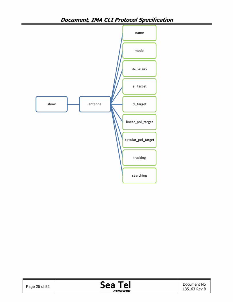
show antenna
name
model
az_target
el_target
cl_target
linear_pol_target
circular_pol_target
tracking
searching

Document, IMA CLI Protocol Specification
Page 26 of 52
Document No
135163 Rev B
show satellite
description
lon
freq
skew
band
tx_pol
search_pattern
reflector
lnb
threshold
auto_mode
auto_offset
value
show ship
name
lat
lon
heading

Document, IMA CLI Protocol Specification
Page 27 of 52
Document No
135163 Rev B
Show System (1 of 4)
show system primary_reflector
trim
el
az
sensitivity
el
az
polang
linear_offset
drive
circular_offset
search
mode
increment
limit
delay
scan_rate
incline_limit
dishscan
mode
az_drive
cl_drive
el_drive
phase
lnb lo band [1-4]

Document, IMA CLI Protocol Specification
Page 28 of 52
Document No
135163 Rev B
Show System (2 of 4)
show system secondary_reflector
trim
el
az
sensitivity
el
az
polang
linear_offset
drive
circular_offset
search
mode
increment
limit
delay
scan_rate
incline_limit
dishscan
mode
az_drive
cl_drive
el_drive
phase
lnb lo band [1-4]

Document, IMA CLI Protocol Specification
Page 29 of 52
Document No
135163 Rev B
Show System (3 of 4)
show system
profile
serial_no
homeflag_trim
satref
blockage_zone zone [1..4]
description
az_start
az_end
el
step_res
ref_limit
az
cl
el balance_mode
tech_contact

Document, IMA CLI Protocol Specification
Page 30 of 52
Document No
135163 Rev B
Show System (4 of 4)
show system
motor_gain
el
cl
az
drive_orientation
el
cl
az vlim_ratio
slow_scan_mode
slow_scan_vlim
auto_sat_load_search_fail
auto_sat_load_reset
num_reflector
receiver

Document, IMA CLI Protocol Specification
Page 31 of 52
Document No
135163 Rev B
show parameter profile
show satellite_fav all
show satellite_fav:x
show error all

Document, IMA CLI Protocol Specification
Page 32 of 52
Document No
135163 Rev B
show status
all
ship
lat
lon
heading
satellite
lon
freq
skew
band
tx_pol
search_pattern
reflector
lnb
agc
threshold
antenna
az
el
cl
pol
rel
agc
initializing
tracking
targeting
searching
system
modem_lock
tx_mute
search_delay_cnt

Document, IMA CLI Protocol Specification
Page 33 of 52
Document No
135163 Rev B
1.0 Command Description:
set Change active settings or parameters.
show Display/query active settings or parameters.
quit Close CLI Ethernet connection.
exit Close CLI Ethernet connection.
save Save parameters or settings to the flash (INI file).
help Display a description for proper command usage.
default all Reset the system to default settings.
reboot Reboot the system.
upgrade Upgrade firmware.
version Display unit name, software date and time of build, and version.
test Run automated tests programmed as part of the system.
2.0 Detailed Command Description: 3. set/show
Set command changes the active settings or parameters. Show command displays the active settings or parameters. 3.1 interface
Stores all interface related settings of the system. 3.1.1 network
Stores all Ethernet related settings, such as IP address, gateway, and port information. 3.1.1.1 mac
Stores the MAC address of the system. Show only. 3.1.1.2 ip_addr
Stores the IP address of the system. 3.1.1.2.1 v4 <default | value>
This set/show the IPv4 address of the system. New IP will take effect after save and reboot. Range: (0-223).(0-255).(0-255).(0-255). Default: 10.1.1.100
3.1.1.3 netmask
Stores the network mask of the system. 3.1.1.3.1 v4 <default | value>
This set/show the IPv4 network mask of the system. New netmask IP will take effect after save and reboot. Range: (0-223).(0-255).(0-255).(0-255). Default: 255.255.255.0
3.1.1.4 gateway
Stores the gateway address of the system. 3.1.1.4.1 v4 <default | value>
This set/show the IPv4 gateway of the system. New gateway IP will take effect after save and reboot. Range: (0-223).(0-255).(0-255).(0-255). Default: 10.1.1.1
3.1.1.5 dns
Stores the DNS (Domain Name System) server address in the network. 3.1.1.5.1 v4 <default | value>
This set/show the IPv4 DNS server in the network. Range: (0-223).(0-255).(0-255).(0-255). Default: 10.1.1.205
3.1.1.6 udp
Stores the UDP port information.

Document, IMA CLI Protocol Specification
Page 34 of 52
Document No
135163 Rev B
3.1.1.6.1 port <default | value>
This set/show the UDP port number. Range: 0-65535. Default: 3000
3.1.1.6.2 enable <default | value>
Enable or disable the port. Value: on, off. Default: on.
3.1.1.7 web
Stores the Web port information. 3.1.1.7.1 port <default | value>
This set/show the Web port number. Range: 0-65535. Default: 80
3.1.1.7.2 enable <default | value>
Enable or disable the port. Value: on, off. Default: on.
3.1.1.8 secure_web
Stores the Secure Web port information. 3.1.1.8.1 port <default | value>
This set/show the Web port number. Range: 0-65535. Default: 443
3.1.1.8.2 enable <default | value>
Enable or disable the port. Value: on, off. Default: on.
3.1.1.9 tcp:0, tcp:1, tcp:2, tcp:3
These groups store the TCP port information. 3.1.1.9.1 port <default | value>
This set/show the port number. Range: 0-65535. Default: tcp:0 = 2000
tcp:1 = 2001 tcp:2 = 2002 tcp:3 = 2003
3.1.1.9.2 enable <default | value>
Enable or disable the port. Value: on, off. Default: on.
3.1.1.9.3 mode <default | value>
This set/show the mode of the port. Value: legacy, openamip, cli. Default:
tcp:0 = legacy tcp:1 = legacy tcp:2 = openamip tcp:3 = cli
3.1.1.9.4 secure <default | value>
This set/show the secure mode of this interface. ON means access to this interface will require proper credential (login). OFF means no credential required. Value: on, off.

Document, IMA CLI Protocol Specification
Page 35 of 52
Document No
135163 Rev B
Default: tcp:0 = off tcp:1 = off tcp:2 = off tcp:3 = on
3.1.2 baudrate
Stores the baud rate for all serial ports. 3.1.2.1 rf_m&c <default | value>
This set/show the baud rate of rf_m&c serial port. Range: 4800 – 115200 (bps). Default: 9600 bps.
3.1.2.2 passthrough <default | value>
This set/show the baud rate of passthrough serial port.
Range: 4800 – 115200 (bps).
Default: 9600 bps.
3.1.2.3 mxp
This set/show the baud rate of MXP’s serial port.
3.1.2.3.1 aux232 <default | value>
This set/show the baud rate of Aux232 serial port.
Range: 4800 – 115200 (bps).
Default: 9600 bps.
3.1.2.3.2 obm_modem <default | value>
This set/show the baud rate of OBM_Modem serial port.
Range: 4800 – 115200 (bps).
Default: 4800 bps.
3.1.2.3.3 nmea_0183 <default | value>
This set/show the baud rate of NMEA 0183 port.
Range: 4800 – 115200 (bps).
Default: 4800 bps.
3.1.2.3.4 console <default | value>
This set/show the baud rate of console port.
Range: 4800 – 115200 (bps).
Default: 115200 bps.
3.1.2.4 icu
This set/show the baud rate of ICU’s serial port.
3.1.2.4.1 console <default | value>
This set/show the baud rate of console serial port.
Range: 4800 – 115200 (bps).
Default: 115200 bps.
3.1.3 nmea_0183
Stores NMEA 0183 settings. 3.1.3.1 message
Stores the GPS message the system sends/streams. Support up to four different settings (defined by the index). 3.1.3.1.1 1, 2, 3, 4 <default | value>
This set/show the GPS message the system sends/streams for particular index. Value: OFF, GGA, GLL, HDD, HDG, HDM, HDT, RMC, VTG. Default: 1 = GLL
2 = GGA 3 = OFF 4 = OFF

Document, IMA CLI Protocol Specification
Page 36 of 52
Document No
135163 Rev B
3.1.3.2 interval
Stores the interval of the GPS message the system sends/streams. Support up to four different settings (defined by the index). 3.1.3.2.1 1, 2, 3, 4 <default | value>
This set/show the interval of the GPS message the system sends/streams for particular index. Range: 1 - 10. Default: 1 = 5
2 = 5 3 = 1 4 = 1
3.1.4 console
Stores console settings. 3.1.4.1 flow_ctrl <default | value>
This set/show the console’s hardware flow control (RTS/CTS). Value: on, off. Default: off.
3.1.4.2 mode <default | value>
This set/show the console’s mode. Value: cli, legacy. Default: cli.
3.1.5 usb_port
Stores USB port settings. 3.1.5.1 mode <default | value>
This set/show the USB port’s mode. In CLI mode it requires credential (login). Value: legacy, cli. Default: cli.
3.1.6 gyro
Stores gyro setting. 3.1.6.1 heading_id <default | value>
This set/show the NMEA 0183 heading ID the system listens to. Value: HDD, HDG, HDM, HDT. Default: HDT.
3.1.6.2 heading <default | value>
This set/show the fixed heading. Value: 0.0 – 360.0 Default: 0.0
3.1.6.3 type <default | value>
This set/show gyro mode. Value: no_gyro, fixed, 360:1, 90:1, 36:1, 1:1, sbs, nmea. Default: fixed.
3.1.7 primary_reflector, secondary_reflector
Stores reflector-specific settings. 3.1.7.1 modem_io <default | value>
This set/show external modem IO type. Value: modem_rj485, tms_1, tms_2, openamip. Default: modem_rj485.
3.1.7.2 xmod_lock_in_pol <default | value>
This set/show external modem lock input polarity for selected modem IO. Determines the polarity (high or low) used by the external modem to indicate lock state. Value: low_lock, hi_lock. Default: low_lock.

Document, IMA CLI Protocol Specification
Page 37 of 52
Document No
135163 Rev B
3.1.7.3 blockage_output <default | value>
This set/show external modem lock input polarity for selected modem IO. Determines the polarity (high or low) used by the external modem to indicate block state. Value: low_block, hi_block. Default: low_block.
3.1.7.4 xmod_lock <default | value>
This set/show external modem lock state. Determines whether the system listen to the lock signal from external modem or not. For Tx/Rx system this option should be on because it is the modem that identifies the satellite. For Rx only system this option should be off since it either uses NID to identify the satellite (via DVB) or the signal-above-threshold. Value: on, off. Default: on.
3.2 antenna
Stores all antenna related settings of the system. 3.2.1 name <default | value>
This set/show antenna name. Support up to 32 characters. Default: [Enter Description]
3.2.2 model <default | value>
This set/show antenna model. Support up to 32 characters. Default: [Enter Model]
3.2.3 az_target <default | value>
This set/show Azimuth target, a position on azimuth axis that the antenna will target. Range: 0.0 – 359.9 (degree) Default: 0.0
3.2.4 el_target <default | value>
This set/show Elevation target, a position on elevation axis that the antenna will target. 0 is the
position when the reflector is facing horizon, parallel to the ground. 90 is the position when the reflector is perpendicular to the ground (high look). Range: 0.0 – 90.0 (degree) Default: 0.0
3.2.5 cl_target <default | value>
This set/show Cross-Level target, a position on cross-level axis that the antenna will target. Range: -30.0 – 30.0 (degree) Default: 0.0
3.2.6 linear_pol_target <default | value>
This set/show linear polarity angle target. Range: -92.0 – 182.0 (degree) Default: 0.0
3.2.7 circular_pol_target <default | value>
This set/show circular polarity angle target. Range: -92.0 – 182.0 (degree) Default: 0.0
3.2.8 tracking <default | value>
This set/show tracking mode state. Value: on, off. Default: on.
3.2.9 searching <default | value>
This set/show searching mode state. Value: on, off. Default: off.

Document, IMA CLI Protocol Specification
Page 38 of 52
Document No
135163 Rev B
3.3 satellite
Stores all antenna related settings of the system. 3.3.1 description <default | value>
This set/show satellite description. Support up to 32 characters. Default: [Enter Description]
3.3.2 lon <default | value>
This set/show satellite longitude. Range: [0.0 - 360.0] [E/W] Default: 101.0 W
3.3.3 freq <default | value>
This set/show satellite frequency. Range: 950.0 – 2150.0 (MHz) Default: 1234.567
3.3.4 skew <default | value>
This set/show satellite skew. Range: -90.0 – 90.0 (degree) Default: 0.0
3.3.5 band <default | value>
This set/show satellite band. Range: 1 - 4 Default: 2
3.3.6 tx_pol <default | value>
This set/show satellite transmit polarity. The possible values cover linear and circular polarization. Value: H, V, L, R. Default: H.
3.3.7 search_pattern <default | value>
This set/show search pattern that is used to search this satellite. Value: spiral, inclined, sky_search. Default: spiral.
3.3.8 reflector <default | value>
This set/show the antenna or reflector that is used for this satellite. Value: primary_reflector, secondary_reflector. Default: primary_reflector.
3.3.9 lnb <default | value>
This set/show the LNB that is used for this satellite. Value: copol, xpol. Default: xpol.
3.3.10 threshold
Stores the threshold settings. The threshold value serves as the main signal threshold to be used for search and dishscan operation. 3.3.10.1 auto_mode <default | value>
This set/show the threshold mode used for this satellite. Value: on, off Default: on.
3.3.10.2 auto_offset <default | value>
This set/show the offset for auto threshold mode. Applicable only when threshold mode is auto. Value: 0 - 300 Default: 100.
3.3.10.3 manual_value <default | value>
This set/show the manual threshold value. Applicable only when threshold mode is auto. Value: 0 - 3000 Default: 100.

Document, IMA CLI Protocol Specification
Page 39 of 52
Document No
135163 Rev B
3.4 ship
Stores ship related settings. 3.4.1 name <default | value>
This set/show the ship name. Support up to 32 characters. Default: [Enter Ship Name]
3.4.2 heading <default | value>
This set/show the ship heading. Range: 0.0 – 360.0 Default: 0.0
3.4.3 lat <default | value>
This set/show the ship latitude. Range: [0.0 - 90.0] [N/S] Default: 0.0 N
3.4.4 lon <default | value>
This set/show the ship longitude. Range: [0.0 - 360.0] [E/W] Default: 0.0 E
3.5 system
Stores system related settings, both reflector-specific and common settings. 3.5.1 primary_reflector, secondary_reflector
Stores reflector-specific settings. 3.5.1.1 auto_thresh
This set will start/initiate calculate Auto Theshold operation. This is an action command. 3.5.1.2 auto_trim
This set will start/initiate calculate Auto Trim operation. This is an action command. 3.5.1.3 trim
Stores trim setting property. Trim is used to apply offset to align the antenna. 3.5.1.3.1 el <default | value>
This set/show trim for elevation axis. Value: -45.0 – 45.0 (degree) Default: 0.0
3.5.1.3.2 az <default | value>
This set/show trim for azimuth axis. Value: -180.0 – 180.0 (degree) Default: 0.0
3.5.1.4 sensitivity
Stores sensitivity settings for elevation and azimuth axes. Sensitivity affects the signal threshold used in dishscan operation. Higher the sensitivity lower the threshold will be. 3.5.1.4.1 el <default | value>
This set/show sensitivity for elevation axis. Range: 10 – 100 (%) Default: 50
3.5.1.4.2 az <default | value>
This set/show sensitivity for elevation axis.
Range: 10 – 100 (%) Default: 50
3.5.1.5 polang
Stores polarity angle of the antenna feed. 3.5.1.5.1 drive <default | value>
This set/show polang drive type. Value: auto, manual. Default: auto

Document, IMA CLI Protocol Specification
Page 40 of 52
Document No
135163 Rev B
3.5.1.5.2 linear_offset <default | value>
This set/show linear polarity angle offset. Applicable only if the type is linear. Range: -45.0 – 45.0 (degree) Default: 0.0
3.5.1.5.3 circular_offset <default | value>
This set/show circular polarity angle offset. Applicable only if the type is circular. Range: -45.0 – 45.0 (degree) Default: 0.0
3.5.1.6 search
Stores search operation settings. Search operation is performed when the antenna is unable to locate a satellite. 3.5.1.6.1 auto <default | value>
This set/show auto search mode. When auto search mode is on (recommended) the antenna will do the search automatically. Value: on, off. Default: on
3.5.1.6.2 increment <default | value>
This set/show search increment value. The increment value determines how big the antenna needs to increment relative to the previous search path/line. Smaller the increment finer the antenna will scan the search area, and it will take longer to reach the search limit. Range: 0.1 – 10.0 (degree) Default: 1.0
3.5.1.6.3 limit <default | value>
This set/show search limit. The limit defines how big the search area. It is measured from the start search position. Range: 1.0 – 20.0 (degree) Default: 20.0
3.5.1.6.4 delay <default | value>
This set/show search delay. This delay determines how long the antenna will wait before initiating the next search when the current search failed. It also determines how long the antenna waits before initiating search operation when the signal dropped below the threshold (lost satellite indication). Range: 0 – 200 (second) Default: 30
3.5.1.6.5 scan_rate <default | value>
This set/show search scan rate. Determines how fast the antenna move during search operation. It is in angular velocity measurement unit. Range: 0.1 – 10.0 (degree/second) Default: 2.0
3.5.1.6.6 incline_limit <default | value>
This set/show incline search limit. Applicable when the search pattern is inclined search. The limit defines how big the search area is. It is measured from the start search position. Range: 2.0 – 40.0 (degree) Default: 16.0
3.5.1.7 dishscan
Stores dishscan operation settings. Dishscan enabled the antenna to keep pointing to a position that give the strongest signal read. During dishscan operation the antenna makes small, circular movement. 3.5.1.7.1 mode <default | value>
This set/show dishscan mode. Enable or disable dishscan. Value: on, off. Default: on.

Document, IMA CLI Protocol Specification
Page 41 of 52
Document No
135163 Rev B
3.5.1.7.2 az_drive <default | value>
This set/show azimuth axis dishscan multiplier value. 0 means no dishscan for azimuth axis. Higher the number bigger the dishscan motion. Range: 0 – 100 Default: 10
3.5.1.7.3 cl_drive <default | value>
This set/show cross-level axis dishscan multiplier value. 0 means no dishscan for cross-level axis. Higher the number bigger the dishscan motion. Range: 0 – 100 Default: 10
3.5.1.7.4 el_drive <default | value>
This set/show elevation axis dishscan multiplier value. 0 means no dishscan for elevation axis. Higher the number bigger the dishscan motion. Range: 0 – 100 Default: 10
3.5.1.7.5 phase <default | value>
This set/show dishscan phase. Dishscan phase is used to control motor output due to movement lagging due to inertia. Large pedestal needs bigger number. Value: -45, 0, 45, 90 Default: 0
3.5.1.8 lnb
Stores LNB related setting. 3.5.1.8.1 lo
Stores Local Oscillator related setting. 3.5.1.8.1.1 band:1, band:2, band:3, band:4 <default | value>
This set/show local oscillator frequency of the LNB. The local oscillator frequency should match the carrier used by the satellite. Range: 1.0 – 200.0 (GHz) Default: band:1 = 10.000
band:2 = 10.700 band:3 = 11.300 band:4 = 9.750
3.5.2 retarget
This set will start/initiate retarget operation. This is an action command. 3.5.3 homeflag_trim <default | value>
This set/show home-flag trim value. Determines the adjustment offset for home-flag sensor. Range: -180.0 – 180.0 (degree) Default: 0.0
3.5.4 satref <default | value>
This set/show satellite reference mode. When Satellite Reference mode is on, the antenna will ignore ship heading and it uses satellite signal to track. Value: on, off. Default: off.
3.5.5 blockage_zone
Stores all blockage-zone configurations. 3.5.5.1 1, 2, 3, 4
Stores blockage-zone configurations based on index. 3.5.5.1.1 description <default | value>
This set/show blockage-zone description. Support up to 32 characters. Default: [Enter Description]
3.5.5.1.2 rel_start <default | value>
This set/show blockage-zone relative start. The relative start for this zone. Range: 0.0 – 360.0 (degree) Default: 0.0

Document, IMA CLI Protocol Specification
Page 42 of 52
Document No
135163 Rev B
3.5.5.1.3 rel_end <default | value>
This set/show blockage-zone relative end. The relative end for this zone. Range: 0.0 – 360.0 (degree) Default: 0.0
3.5.5.1.4 el <default | value>
This set/show blockage-zone elevation. Determines the end of elevation for this zone. The
start of elevation is always at elevation = 0. Range: 0.0 – 90.0 (degree) Default: 90.0
3.5.6 profile <default | value>
This set/show hardware profile ID of the system. Please find the hardware profile ID on the sticker attached to the antenna. Default: 0.
3.5.7 serial_number
Stores serial number. Show only. 3.5.8 auto_sat_load_search_fail <default | value>
This set/show auto satellite load after search failed. When the mode is on, the antenna will load and go to the last known good satellite when the search operation failed. Value: on, off. Default: on.
3.5.9 auto_sat_load_reset <default | value>
This set/show auto satellite load after hot reset or power up. When the mode is on, the antenna will load and go to the last known good satellite upon hot reset or power up. Value: on, off. Default: on.
3.5.10 step_res <default | value>
This set/show step resolution. Step resolution determines the step size for 1 move during search operation. Value: 0.2, 0.1, 0.05 (degree) Default: 0.1
3.5.11 balance_mode <default | value>
This set/show balance mode. When in balance mode the antenna will not moving and allow the technician to balance the antenna. Value: on, off. Default: off
3.5.12 ref_limit
Stores reference limit mode for all axes. When Reference Limit mode is on, the system will clip the
error to 3. This is mainly used in the land, where the abrupt erratic movement of the vehicle introduces abrupt error. 3.5.12.1 az <default | value>
This set/show reference limit mode for azimuth axis. Value: on, off. Default: off.
3.5.12.2 cl <default | value>
This set/show reference limit mode for cross-level axis. Value: on, off. Default: off.
3.5.12.3 el <default | value>
This set/show reference limit mode for elevation axis. Value: on, off. Default: off.
3.5.13 motor_gain
Stores motor gain for all axes. The gain determines the motor torque. Antenna system with large pedestal required higher gain than the one with smaller pedestal.

Document, IMA CLI Protocol Specification
Page 43 of 52
Document No
135163 Rev B
3.5.13.1 az <default | value>
This set/show azimuth motor gain. Range: 0 - 500. Default: 15 (model specific database will override).
3.5.13.2 cl <default | value>
This set/show cross-level motor gain. Range: 0 - 500. Default: 15 (model specific database will override).
3.5.13.3 el <default | value>
This set/show azimuth motor gain. Range: 0 - 500. Default: 15 (model specific database will override).
3.5.14 drive_orientation
Stores motor drive orientation all axes. This setting will determine how the motor installed or mounted on the pedestal (model-specific). E.g. Clockwise move is forward move for Azimuth axis. If the azimuth motor is installed in reverse position, a positive output to the motor will result in the pedestal move counter clockwise on azimuth axis. In this case the drive orientation for azimuth motor will be reverse. 3.5.14.1 az <default | value>
This set/show azimuth motor drive orientation. Value: fwd, rev. Default: fwd (model specific database will override).
3.5.14.2 cl <default | value>
This set/show cross-level motor drive orientation. Value: fwd, rev. Default: fwd (model specific database will override).
3.5.14.3 el <default | value>
This set/show elevation motor drive orientation. Value: fwd, rev. Default: fwd (model specific database will override).
3.5.15 vlim_ratio <default | value>
This set/show velocity limit ratio. Velocity limit ratio is the scale factor that is applied to prevent the overshooting from happening by limiting the velocity of the antenna. Closer the antenna to the target, lower the limit will be. Bigger the pedestal, bigger the ratio will be. Value: 1 - 8. Default: 1 (model specific database will override).
3.5.16 slow_scan_mode <default | value>
This set/show slow scan mode. When the mode is on, the antenna will be in slow scan mode. This is used for testing and diagnostic only. Value: on, off. Default: off.
3.5.17 slow_scan_vlim <default | value>
This set/show slow scan velocity limit. Similar to velocity limit, but this one applies when the antenna is in slow scan mode. Range: 0.1 – 9.9. Default: 2.0.
3.5.18 num_reflector <default | value>
This set/show the number of reflectors the antenna has. When the number of reflector is one, only the primary sections under system will be available. Range: 1 – 2. Default: 1.
3.5.19 receiver <default | value>
This set/show the receiver type. Range: NBIF, SCPC, DVB, 70MHZ. Default: SCPC.

Document, IMA CLI Protocol Specification
Page 44 of 52
Document No
135163 Rev B
3.5.20 tech_contact
This show technical contact information. Show only. Value: Sea Tel Inc., a Cobham company 4030 Nelson Ave. Concord, CA 94520 USA E: [email protected] T: +1 (925) 798-2399
3.6 satellite_fav
3.6.1 new
Add a new favorite satellite. This is interactive mode command. First it will display the index of this new favorite satellite, and then it will prompt to enter each satellite parameters one by one.
3.6.2 0 - 499
Favorite satellite with index. It’s written with colon as separator. Example: satellite_fav:1 3.6.2.1 clear
This deletes the favorite satellite. 3.6.2.2 active
This sets the favorite satellite to be the active satellite. The antenna will target this satellite.
3.7 status
3.7.1 ship
Show ship related settings. 3.7.1.1 heading
This show the ship heading. Range: 0.0 – 360.0 Default: 0.0
3.7.1.2 lat
This show the ship latitude. Range: 90.0 N – 90.0 S Default: 0.0 N
3.7.1.3 lon
This show the ship longitude. Range: [0.0 - 360.0] [E/W] Default: 0.0 E
3.7.2 satellite
Stores all antenna related settings of the system. 3.7.2.1 lon
This show satellite longitude. Range: 180.0 W – 180.0 E Default: 0.0 E
3.7.2.2 freq
This show satellite frequency. Range: 950.0 – 2150.0 (MHz) Default: 1234.567
3.7.2.3 skew
This show satellite skew. Range: -90.0 – 90.0 (degree) Default: 0.0
3.7.2.4 band
This show satellite band. Range: 1 - 4 Default: 1

Document, IMA CLI Protocol Specification
Page 45 of 52
Document No
135163 Rev B
3.7.2.5 tx_pol
This show satellite transmit polarity. Value: H, V, L, R. Default: H.
3.7.2.6 search_pattern
This show search pattern that is used to search this satellite. Value: spiral, inclined, sky_search. Default: spiral.
3.7.2.7 reflector
This show the reflector that is used for this satellite. Value: primary_reflector, secondary_reflector. Default: primary_reflector.
3.7.2.8 lnb
This show the LNB that is used for this satellite. Value: copol, xpol. Default: xpol.
3.7.2.9 agc
This show the AGC value. 3.7.2.10 threshold
This show the actual threshold value being used by the antenna. 3.7.3 antenna
Stores all antenna related settings of the system. 3.7.3.1 az
This show current Azimuth position. Range: 0.0 – 360.0 (degree) Default: 0.0
3.7.3.2 el
This show current Elevation position. Range: 0.0 – 90.0 (degree) Default: 0.0
3.7.3.3 cl
This show current Cross-Level position. Range: -30.0 – 30.0 (degree) Default: 0.0
3.7.3.4 relative
This show current Relative position. Range: 0.0 – 360.0 (degree) Default: 0.0
3.7.3.5 linear_pol
This show current linear polarity angle. Range: -92.0 – 182.0 (degree) Default: 0.0
3.7.3.6 circular_pol
This show current circular polarity angle. Range: -92.0 – 182.0 (degree) Default: 0.0
3.7.3.7 agc
This show AGC value. 3.7.3.8 initializing
This show initializing mode state. Value: on, off.
3.7.3.9 tracking
This show tracking mode state. Value: on, off.

Document, IMA CLI Protocol Specification
Page 46 of 52
Document No
135163 Rev B
3.7.3.10 targeting
This show targeting mode state. Value: on, off.
3.7.3.11 searching
This show searching mode state. Value: on, off.
3.7.4 system
Stores system related settings. 3.7.4.1 modem_lock
This show modem lock status the system got from modem. Value: on, off.
3.7.4.2 tx_mute
This show the cause of transmit mute. Transmit mute can happen because the antenna is in the blockage zone, manually muted, or due to stability. Value: manual, stability, block, and threshold.
3.7.4.3 search_delay_count
This show the search delay count left. It is a countdown.
3.8 error
Clears/acknowledges or shows error(s).
3.8.1 messages
This set enables/disables the critical error messages on Console port. For “off”, it disables temporarily (for 5 minutes). Value: on, off.
3.8.2 clear
This set clears/acknowledges error. Value: all, [error number].
3.8.3 all
This show displayed all errors.
4. save
Save without any parameter will perform system settings save.
4.1.1 dealer_config
This will create a dealer_config file. The dealer will later can restore this config.
5. restore
Restore settings.
5.1.1 dealer_config
This will restore settings from dealer_config file in the system.
5.1.2 factory
Reset all parameters back to factory default. Exception: profile ID and all settings under interface (such as: IP configuration, serial baudrate, gyro, modem settings).
6. Login
There are three usernames with different level of authorization, and they are case-sensitive: Dealer (default password: seatel3), SysAdmin (default password: seatel2), and User (default password: seatel1).

Document, IMA CLI Protocol Specification
Page 47 of 52
Document No
135163 Rev B
7. Control Character
Character Name Hex Value Impact
Carriage Return 0x0D Command Terminator
Line Feed 0x0A Command Terminator
Space 0x20 Command and Argument Delimiter
Backspace 0x08 Delete one character on the left side of the cursor.
Escape 0x1B Abort Current Command
Up Arrow 0x1B 0x5B 0x41 Previous Command History
Down Arrow 0x1B 0x5B 0x42 Next Command History 8. Planned Features
8.1.1 Auto Complete using Tab button. 8.1.2 Machine to Machine IMA CLI Protocol

Document, IMA CLI Protocol Specification
Page 48 of 52
Document No
135163 Rev B
3.0 Legacy M&C and Modem Commands: In order to ensure full backwards compatibility for existing modems and automated user interfaces, the following commands from the DAC commands set (PN: 127060) have been implemented.
Commands Name Notes
esc References
H Relative AZ / Ships Heading
q Tuner Information S Status P Az/El/Cl Position Decimal
p Az/El/Cl Position Hex
u Read Polang, Aux/Ext AGC, Threshold
C Tracking (Step Track / DishScan) ON. D Tracking (Step Track / DishScan) OFF.
W Write parameters to NV RAM. Use ‘\
& Clear current Error Status
V Software Version F↵ Target current Satellite (Find) gets raw coarse PCU GPS position gets raw fine PCU GPS position ?x↵ IVCs
?y↵ TCs
?@ ↵ Qualified GPS query, 1 min resolution
?V gets PCU Version Number Aaaaa↵ Azimuth
Baaaa Set ships heading to ‘aaa.a’ degrees Eaaaa↵ Elevation Oxxxx Set PCU Digital output ports to ‘xxxx’. Tnnnn↵ Satellite longitude baaaa↵ Set ships heading to 'aaa.a' degrees without changing azimuth.
c0028↵ Set ADE Band Aux OFF(Xp) and Reflector B c0029↵ Set ADE Band Aux ON(Cp) and Reflector B c0030↵ Set active Reflector to Reflector A c0031↵ Set active Reflector to Reflector B c0032↵ Set DVB receiver tone OFF maps to c0048
c0033↵ Set DVB receiver tone ON maps to c0049
c0034↵ Set DVB receiver volt = 13 V maps to c0038
c0035↵ Set DVB receiver volt = 18 V maps to c0039
c0036↵ Set ADE Band Aux Off
c0037↵ Set ADE Band Aux On
c0038↵ Set ADE Band Volt = 13
c0039↵ Set ADE Band Volt = 18
c0040↵ Set ADE Band T, Band V, Band Aux (0,0,0)
c0041↵ Set ADE Band T, Band V, Band Aux (0,1,0)
c0042↵ Set ADE Band T, Band V, Band Aux (0,0,1)
c0043↵ Set ADE Band T, Band V, Band Aux (0,1,1)
c0044↵ Set ADE Band T, Band V, Band Aux (1,0,0)
c0045↵ Set ADE Band T, Band V, Band Aux (1,1,0)
c0046↵ Set ADE Band T, Band V, Band Aux (1,0,1) c0047↵ Set ADE Band T, Band V, Band Aux (1,1,1) c0048↵ Set ADE Band Tone Off

Document, IMA CLI Protocol Specification
Page 49 of 52
Document No
135163 Rev B
c0049↵ Set ADE Band Tone On
cnnnn↵ Tuning freq (MHz) or DVB/RF mode Also, c00XX cmds
above
dnnnn↵ Baudrate or KHz gnnn↵ Set 24v polang position to ‘nnn’.
tnnnn↵ Target NID wV*** Read DVB Version Jaaaa Move azimuth to ship relative ‘aaa.a’ degrees nAnnn Set or Read PCU “N” parameter at index ‘A’ with value ‘nnn’ mbnnn Lat mcnnn Lat mdnnn Lat ns m•nnn TDisp• m}nnn↵, m~nnn↵ Saved (Target) NID mAnnn↵ A=138 SatSkew mhnnn↵, minnn↵ Satellite Long mjnnn↵ Satellite E/W mQnnn↵ 24v Polang Offset munnn↵ FEC Tone Volt
mWnnn↵ Polang Tx Type
mEnnn NA mFnnn agc th mGnnn El Step Size mHnnn Az Step Size mInnn Step Integral mNnnn System Type mOnnn Gyro Type mPnnn Polang Type mRnnn 24v Polang Scale mSnnn Az Limit 1 mTnnn Az Limit 1 mUnnn AZ Limit 2 mVnnn AZ Limit 2 mWnnn Polang Tx Type mYnnnmZnnn AZ Limit3 m[nnnm\nnn AZ Limit4 m]nnnm^nnn AZ Limit5 m_nnnm`nnn AZ Limit6 m~nnn Saved (Target) NID munnn FEC Tone Volt mJnnn Search Inc mKnnn Search Limit mLnnn Search Delay mMnnn Scan rate mAnnnmBnnn El Trim mgnnnmhnnn Lon minnn Lon ew
mCnnnmDnnn Az Trim
mhnnnminnn SAT
mjnnn Sat ew monnnmpnnn THRS
mqnnnmrnnn MHZ

Document, IMA CLI Protocol Specification
Page 50 of 52
Document No
135163 Rev B
msnnnmtnnn KHZ
mvnnn POL SEL m{nnnm|nnn Remote POL
m’nnnmƒnnn AZ Limit7 / Pol5 O/S
m†nnn EL Limit12 m‡nnn EL Limit34 mˆnnn EL Limit56
$mmmm↵ NMEA Latitude - Longitude / Heading input (GLL / HDT / HDM format).
\nnnn↵ Send Utility command ‘\nnnn’ to ACU. See section 2.2 for
details(below) \0066↵ Perform Auto Trim and start Auto Threshold calculations.
\0067↵ Complete Auto Threshold calculation
\0080↵ Start ACU FLASH Programming Mode
\0082↵ Reset ACU Parameters to factory defaults
\0087↵ Write ACU Parameters to Non Volatile storage
\0090 Reboot the ACU.
\0091 MXP Bootloader Version \0092 ICU Bootloader version
^nnnn Send Utility command ‘^nnnn’ to PCU. See PCU command summary
[V View CommIF version [0nnnnn Set TCP/IP-0 port number (M&C Port 0, Sea Tel) [1nnnnn Set TCP/IP-1 port number (M&C Port 1, Sea Tel) [2nnnnn Set TCP/IP-2 port number (M&C Port 2, OpenAMIP). [Gnnn.nnn.nnn.nnn Set Gateway address
[Innn.nnn.nnn.nnn Set IP address [Nnnn.nnn.nnn.nnn Set Net mask
[Qnnn or [Q Set the port security mask [S Start serial upload mode (for advanced users only) [Tnnnnn Set HTTP port number (Webserver).
[Unnnnn Set UDP port number (SHD Software Upload) [W Write Comm IF parameters to flash. [Z Soft reboot the Comm IF module. [?x View settings for ‘x’ where ‘x’ is any combination of:
- Null for CommIF settings (legacy default) - A for Antenna Control Unit settings.
- P for Pedestal Control Unit settings - M for Motor Control Unit firmware version
- > for Above Decks Modem firmware version
- < for Below Decks Modem firmware version - R for Receiver firmware version
- C for CommIF settings - Z for a parameter dump of all settings
[Xssssssss Set the access username to "ssssssss". Must be 4-8 characters
long [Yssssssss Set the access password to "ssssssss". Must be 4-8 characters
long [Dxnnnnn or [Dx Set the local oscillator on band 'x' to nnnnn

Document, IMA CLI Protocol Specification
Page 51 of 52
Document No
135163 Rev B
4.0 Profile Number Table: The following table defines which system corresponds to which Profile numbers inside the profile number database: System Name Profile Number Software Version Implemented 4012GX 1 Initial

Document, IMA CLI Protocol Specification
Page 52 of 52
Document No
135163 Rev B
5.0 Error Table:
The following table defines the total number of errors which may be reported by the IMA software:
Error Code Description Type Front Panel LED*
(Un)Latched** Type State Color
1001 Stability Limit Error Error Solid Red Unlatched
1002 Az Reference Error (Encoder Read) Error Error Solid Red Latched
1003 AGC Below Noise Threshold Error Error Solid Red Unlatched
1004 Software Update Did not Load Properly Warning Error Solid Red Latched
1005 Comm Error w/ Motor Driver Error Error Solid Red Latched
1006 Motor Driver Fault Detected Error Error Solid Red Latched
1007 DishScan Disabled Error Error Solid Red Unlatched
1008 AZ Reference Error (Home Flag Read) Error Error Solid Red Latched
1009 Tilt Sensor Error Error Error Solid Red Unlatched
1010 Rate Sensor Error Error Error Solid Red Unlatched
1011 Over Speed Error Error Error Solid Red Latched
1012 POST Failure Debug Error Solid Red Latched
1013 OS Errors Warning Error Solid Red Unlatched
1014 Flash Failure Error Error Solid Red Latched
1015 MXP/ICU Link Error Warning Error Solid Red Unlatched
1016 Az Servo Limit Error Error Flashing Red Latched
1017 LV Servo Limit Error Error Flashing Red Latched
1018 CL Servo Limit Error Error Flashing Red Latched
1019 No GPS String Error Error Flashing Red Unlatched
1020 No Profile Set in PCU Error Error Flashing Red Latched
1021 NMEA HDD Heading Not Received for 10 Seconds Error Error Solid Red Latched
1022 NMEA HDG Heading Not Received for 10 Seconds Error Error Solid Red Latched
1023 NMEA HDM Heading Not Received for 10 Seconds Error Error Solid Red Latched
1024 NMEA HDT Heading Not Received for 10 Seconds Error Error Solid Red Latched
1025 GPS String Invalid Warning Error Flashing Yellow Unlatched
1026 Antenna Not Balanced Warning Error Flashing Red Unlatched
1027 Satellite Out of Range Info Target Solid Red Unlatched
1028 Temp In Radome Above/Below Operating Specs Warning Error Solid Yellow Unlatched
1029 Antenna about to enter a Programmed Block Zone Notice Tracking Flashing Yellow Unlatched
1030 Antenna Within a Programmed Block Zone Notice Tracking Solid Yellow Unlatched
1031 AGC Below Threshold Info Tracking Solid Yellow Unlatched
1032 Latest Parameters Not Saved Notice Error Flashing Yellow Unlatched
1033 Software Update In Progress Info Initializing Flashing Yellow Unlatched
1034 Block Zone Test/Simulation Info Tracking Flashing Yellow Unlatched
1035 MXP-ICU Sync Timeout Info Error Flashing Yellow Unlatched
1036 Parameter Sync Error Warning Error Flashing Red Latched
1037 Time Sync Error Warning Error Flashing Red Latched
1038 System Serial Number Mismatch Error Error Solid Yellow Unlatched
1039 System Serial Number Invalid Error Error Solid Yellow Unlatched
1040 INI Integrity Error Warning Error Flashing Red Latched
1041 NMEA HDD Received with Bad Checksum Notice Error Solid Yellow Latched
1042 NMEA HDG Received with Bad Checksum Notice Error Solid Yellow Latched
1043 NMEA HDM Received with Bad Checksum Notice Error Solid Yellow Latched
1044 NMEA HDT Received with Bad Checksum Notice Error Solid Yellow Latched
1045 Step by Step Gyro Took Invalid Step Size Warning Error Solid Yellow Latched
1046 Step by Step Gyro Not Connected Correctly Error Error Solid Red Latched
1047 Step by Step Gyro Requires Initial Heading Notice Error Solid Red Unlatched
1048 36:1 Synchro Gyro Requires Initial Heading Notice Error Solid Red Unlatched
1049 90:1 Synchro Gyro Requires Initial Heading Notice Error Solid Red Unlatched
1050 360:1 Synchro Gyro Requires Initial Heading Notice Error Solid Red Unlatched
1051 1:1 Synchro Gyro Is Not Properly Connected Error Error Solid Red Latched
1052 36:1 Synchro Gyro Is Not Properly Connected Error Error Solid Red Latched
1053 90:1 Synchro Gyro Is Not Properly Connected Error Error Solid Red Latched
1054 360:1 Synchro Gyro Is Not Properly Connected Error Error Solid Red Latched
1055 Polang skew entry results in target out of range Error Error Flashing Red Latched
1056 Motor failed to reach Target Error Error Solid Red Latched
* Front Panel LEDs have the following priority, from highest to lowest: Solid Red, Flashing Red, Solid Yellow, Flashing Yellow, Solid Green, Flashing Green. ** An unlatched error can automatically clear itself, if the system corrects the condition which caused the error. A latched error can only be cleared explicitly by the user.