Embed Size (px)
Citation preview
SST-PFB-CLX-RLL
User Reference Guide
Document Edition: 1.8
Document #: 715-0022
User Reference Guide SST-PFB-CLX-RLL
ii
©2008 Woodhead Industries Inc. Document Edition: 1.8, Document #: 715-0022, Template Edition: 1.1, Template #: QMS-06-045
Use, duplication or disclosure of this document or any of the information contained herein is subject to the restrictions on page ii of this document.
Document Edition: 1.8
Date: May 5, 2008
This document applies to the SST-PFB-CLX-RLL scanner module.
Copyright ©2008 Woodhead Industries Inc.
This document and its contents are the proprietary and confidential property of Woodhead Industries Inc. and/or its related companies and may not be used or disclosed to others without the express prior written consent of Woodhead Industries Inc. and/or its related companies.
SST is a trademark of Woodhead Industries Inc. All other trademarks belong to their respective companies.
At Woodhead, we strive to ensure accuracy in our documentation. However, due to rapidly evolving products, software or hardware changes occasionally may not be reflected in our documents. If you notice any inaccuracies, please contact us (see Appendix D).
Written and designed at Woodhead Software & Electronics, 50 Northland Road, Waterloo, Ontario, Canada N2V 1N3.
Hardcopies are not controlled.
SST-PFB-CLX-RLL User Reference Guide
Contents iii
©2008 Woodhead Industries Inc. Document Edition: 1.8, Document #: 715-0022, Template Edition: 1.1, Template #: QMS-06-045
Use, duplication or disclosure of this document or any of the information contained herein is subject to the restrictions on page ii of this document.
Contents
Preface ......................................................................................................................... vii Purpose of this Guide ............................................................................................................... viii Special Notation ....................................................................................................................... viii
System Overview .......................................................................................................... 9 1.1 System Overview..................................................................................................................10
1.1.1 Scanner Capabilities.......................................................................................................10 1.1.2 Configuring the Scanner.................................................................................................11 1.1.3 Scanning Network and I/O Status ..................................................................................11 1.1.4 Operating Modes ............................................................................................................12
Hardware Overview..................................................................................................... 13 2.1 Hardware Features................................................................................................................14
2.1.1 Status LEDs....................................................................................................................15 2.1.2 9-Pin PROFIBUS Connector .........................................................................................16 2.1.3 Configuration Port..........................................................................................................16
Quick Start ................................................................................................................... 17 3.1 Purpose .................................................................................................................................18 3.2 Equipment and Tools............................................................................................................18 3.3 Package Contents..................................................................................................................18 3.4 Power Requirements.............................................................................................................19 3.5 Procedures ............................................................................................................................19
3.5.1 Setting up the Scanner....................................................................................................19 3.5.2 Getting the Scanner Running .........................................................................................20
User Reference Guide SST-PFB-CLX-RLL
iv Contents
©2008 Woodhead Industries Inc. Document Edition: 1.8, Document #: 715-0022, Template Edition: 1.1, Template #: QMS-06-045
Use, duplication or disclosure of this document or any of the information contained herein is subject to the restrictions on page ii of this document.
Installing the SST-PFB-CLX-RLL Scanner ................................................................ 234.1 Installing the Scanner Module..............................................................................................24
4.1.1 Installation Procedure.....................................................................................................24 4.1.2 Removal Procedure ........................................................................................................24
4.2 PROFIBUS Wiring...............................................................................................................25 4.2.1 Selecting the Proper Line Type......................................................................................26 4.2.2 PROFIBUS Connector ...................................................................................................27
4.3 PROFIBUS LED and Display States ...................................................................................28 4.3.1 LED and Display Combinations ....................................................................................29 4.3.2 Display Tables................................................................................................................30
Configuring and Programming the DP Master ......................................................... 31 5.1 Configuring the Scanner.......................................................................................................32
5.1.1 Configuring Through RSLogix 5000 .............................................................................32 5.1.2 Configuring Through PlantScape Control Builder.........................................................36
5.2 Creating an I/O Configuration..............................................................................................37 5.2.1 Configuring the SST-PFB-CLX-RLL Card as a DP Master..........................................38 5.2.2 Online Browsing with DP View in the SST PROFIBUS Tool ......................................51
5.3 Downloading to the Scanner.................................................................................................61 5.3.1 Downloading the DP Master Configuration File to the Scanner ...................................61 5.3.2 Downloading to the Scanner via the SST PROFIBUS Configuration Tool ..................62 5.3.3 Monitoring the Scanner via the SST PROFIBUS Configuration Tool ..........................65 5.3.4 Reconnecting to the Scanner when it’s Already Configured and Online ......................67 5.3.5 Diagnosing Slave Errors in the SST PROFIBUS Configuration Tool...........................68
5.4 Troubleshooting....................................................................................................................69 5.5 Importing the DP Master Binary Configuration (.bss) Using the Configuration Tool ........71
5.5.1 Uploading the DP Master Configuration File from the Scanner Using the SST PROFIBUS Configuration Tool..............................................................................................73
5.6 Downloading the I/O Configuration to the Scanner Using HyperTerminal.........................75 5.6.1 Listing Available Commands.........................................................................................77 5.6.2 Exiting Config Mode......................................................................................................78
5.7 Errors ....................................................................................................................................78 5.7.1 Network Parameter Errors..............................................................................................78 5.7.2 Binary File Configuration Errors ...................................................................................79 5.7.3 Flash Programming Errors .............................................................................................79 5.7.4 Fatal Errors.....................................................................................................................80
5.8 Running the Scanner.............................................................................................................80 5.8.1 CLX Modes ....................................................................................................................81 5.8.2 PBIM Modes ..................................................................................................................81
5.9 SST-PFB-CLX-RLL I/O and Status Images ........................................................................82 5.10 Making Changes to the CLX Configuration File While the PROFIBUS Card is Online ..91
SST-PFB-CLX-RLL User Reference Guide
Contents v
©2008 Woodhead Industries Inc. Document Edition: 1.8, Document #: 715-0022, Template Edition: 1.1, Template #: QMS-06-045
Use, duplication or disclosure of this document or any of the information contained herein is subject to the restrictions on page ii of this document.
System Diagnostics .................................................................................................... 93 6.1 PFB Status Register ..............................................................................................................94
6.1.1 Scanner Firmware Version Number...............................................................................95 6.1.2 DP Master Active and Configured Slave Station Bit Tables .........................................96 6.1.3 Reading the Slave Diagnostics.......................................................................................98
6.2 Diagnostic Counters ...........................................................................................................100 6.2.1 General Statistics..........................................................................................................102 6.2.2 DP Master Statistics .....................................................................................................103 6.2.3 ASPC2 PROFIBUS Controller Statistics.....................................................................104
6.3 Summary of Diagnostic Locations .....................................................................................106
DP Master Application Examples............................................................................. 107 7.1 Addressing..........................................................................................................................108
7.1.1 I/O Data Packing Examples .........................................................................................108 7.2 Main CLX Example ...........................................................................................................109 7.3 Reading Slave Diagnostics .................................................................................................111
7.3.1 Example: Using Flex I/O..............................................................................................114
Upgrading the Scanner Firmware............................................................................ 117 8.1 Upgrading the Scanner Firmware.......................................................................................118
Network Parameter Defaults .................................................................................... 121 9.1 Network Parameter Default Values....................................................................................122
Slave Functionality.................................................................................................... 125 10.1 SST-PFB-CLX-RLL DP Slave Features ..........................................................................126 10.2 Register Definitions and Layout.......................................................................................127
10.2.1 DP Slave Status Table Entries....................................................................................127 10.2.2 I/O Table Additions/Modifications ............................................................................129 10.2.3 Config Table Additions..............................................................................................129 10.2.4 LED and LCD Behavior Modifications .....................................................................132
10.3 Slave Configuration and Programming ............................................................................133 10.3.1 Configuring the CLX Slave in RSLogix 5000 ...........................................................134
DPV1 Master Functionality ....................................................................................... 135 11.1 General Features ...............................................................................................................136 11.2 DPV1-Supported Functions..............................................................................................136 11.3 DPV1 Command Description...........................................................................................137
11.3.1 Overview ....................................................................................................................137 11.3.2 DPV1 Init Command..................................................................................................138 11.3.3 DPV1 Exit Command.................................................................................................139
User Reference Guide SST-PFB-CLX-RLL
vi Contents
©2008 Woodhead Industries Inc. Document Edition: 1.8, Document #: 715-0022, Template Edition: 1.1, Template #: QMS-06-045
Use, duplication or disclosure of this document or any of the information contained herein is subject to the restrictions on page ii of this document.
11.3.4 DPV1 Class 1 Read Command ..................................................................................140 11.3.5 DPV1 Class 1 Write Command .................................................................................142 11.3.6 DPV1 Initiate Command............................................................................................143 11.3.7 DPV1 Class 2 Abort Command .................................................................................146 11.3.8 DPV1 Class 2 Read Command ..................................................................................147 11.3.9 DPV1 Class 2 Write Command .................................................................................150 11.3.10 DPV1 Class 2 Idle Command ..................................................................................152 11.3.11 Extended Error Code................................................................................................154
11.4 Creating a CIP Generic Message for Transmitting a DPV1 Command...........................156 11.5 DPV1 Sample Code..........................................................................................................161
11.5.1 DPV1 MC1 Initialization Example ............................................................................161 11.5.2 DPV1 Class 1 Read Example.....................................................................................163 11.5.3 DPV1 MC2 Initialization Example ............................................................................164 11.5.4 DPV1 Class 2 Read Example.....................................................................................167 11.5.5 Copy DPV1 Initiate Parameters .................................................................................169
Using the Configuration Tool through RSLinx ....................................................... 171 12.1 Configuration Tool Overview ..........................................................................................172 12.2 Functions ..........................................................................................................................172 12.3 Configuring the RSLinx Connection................................................................................173 12.4 DPV1 Features..................................................................................................................174
I/O Expansion ............................................................................................................ 175 13.1 I/O Expansion Overview ..................................................................................................176 13.2 Assigning I/O Offsets in Your Configuration ..................................................................177 13.3 I/O Expansion Ladder Samples ........................................................................................179
Setting up the RSLinx Driver.................................................................................... 181 A.1 Installing and Configuring the RSLinx Driver ..................................................................182
Technical Specifications .......................................................................................... 185 B.1 Technical Specifications ....................................................................................................186
CE Compliance.......................................................................................................... 187 C.1 CE Compliance ..................................................................................................................188
Warranty and Support............................................................................................... 189 D.1 Warranty ............................................................................................................................190 D.2 Reference Documents........................................................................................................190 D.3 Technical Support..............................................................................................................191
D.3.1 Getting Help ................................................................................................................192
SST-PFB-CLX-RLL User Reference Guide
Preface vii
©2008 Woodhead Industries Inc. Document Edition: 1.8, Document #: 715-0022, Template Edition: 1.1, Template #: QMS-06-045
Use, duplication or disclosure of this document or any of the information contained herein is subject to the restrictions on page ii of this document.
Preface
Preface Sections:
• Purpose of this Guide
• Special Notation
User Reference Guide SST-PFB-CLX-RLL
Purpose of this Guide This manual is a user's guide for the SST ControlLogix (CLX) PROFIBUS scanner module, commonly known as the SST-PFB-CLX-RLL. Use this guide if you are responsible for installing, programming or troubleshooting control systems that use Allen-Bradley CLX processors or Honeywell PlantScape Control processors and the SST-PFB-CLX-RLL scanner. For more information on Honeywell's PlantScape system, refer to Section D2, Reference Documents. It is assumed that you have a basic understanding of PLCs and are familiar with PROFIBUS modules and the PROFIBUS network.
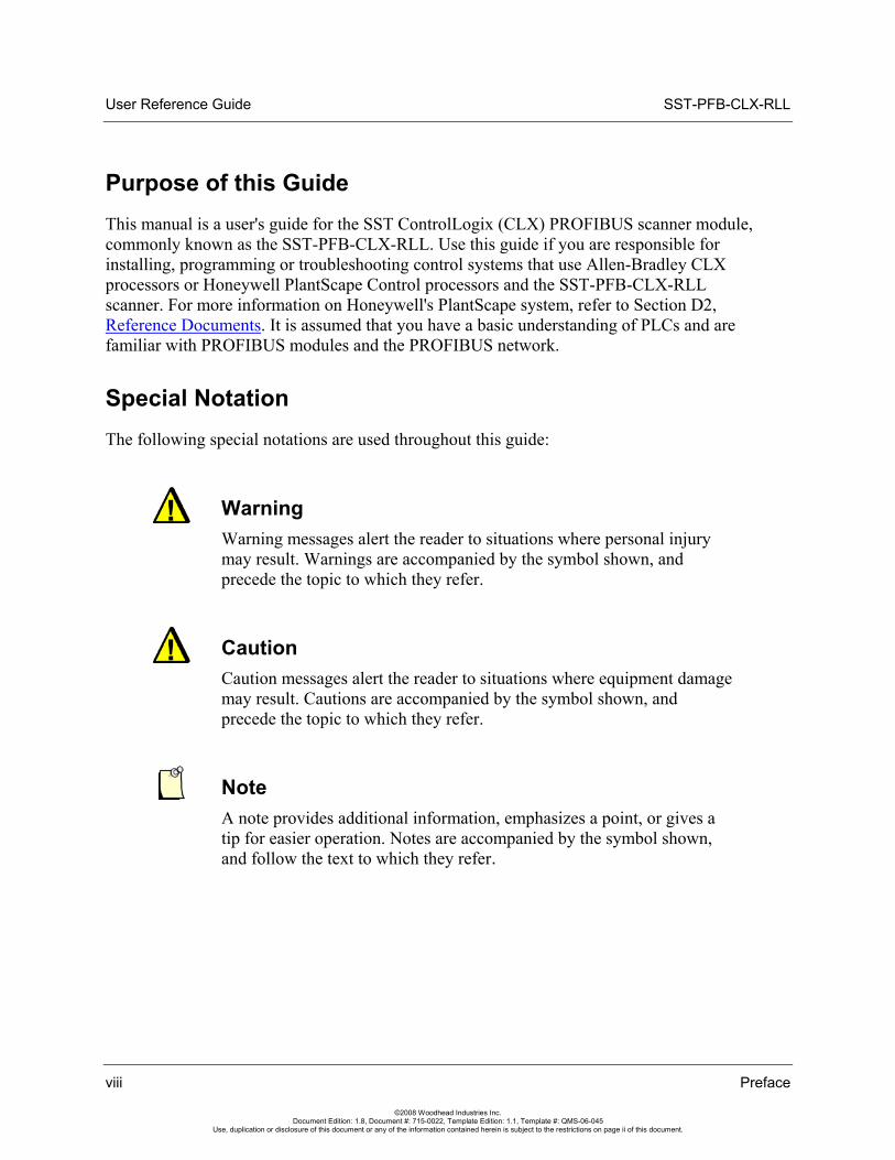
Special Notation The following special notations are used throughout this guide:
Warning Warning messages alert the reader to situations where personal injury may result. Warnings are accompanied by the symbol shown, and precede the topic to which they refer.
Caution Caution messages alert the reader to situations where equipment damage may result. Cautions are accompanied by the symbol shown, and precede the topic to which they refer.
Note A note provides additional information, emphasizes a point, or gives a tip for easier operation. Notes are accompanied by the symbol shown, and follow the text to which they refer.
viii Preface
©2008 Woodhead Industries Inc. Document Edition: 1.8, Document #: 715-0022, Template Edition: 1.1, Template #: QMS-06-045
Use, duplication or disclosure of this document or any of the information contained herein is subject to the restrictions on page ii of this document.
SST-PFB-CLX-RLL User Reference Guide
System Overview 9
©2008 Woodhead Industries Inc. Document Edition: 1.8, Document #: 715-0022, Template Edition: 1.1, Template #: QMS-06-045
Use, duplication or disclosure of this document or any of the information contained herein is subject to the restrictions on page ii of this document.
1 System Overview
Chapter Sections:
• System Overview
User Reference Guide SST-PFB-CLX-RLL
10 System Overview
©2008 Woodhead Industries Inc. Document Edition: 1.8, Document #: 715-0022, Template Edition: 1.1, Template #: QMS-06-045
Use, duplication or disclosure of this document or any of the information contained herein is subject to the restrictions on page ii of this document.
1.1 System Overview
1.1.1 Scanner Capabilities
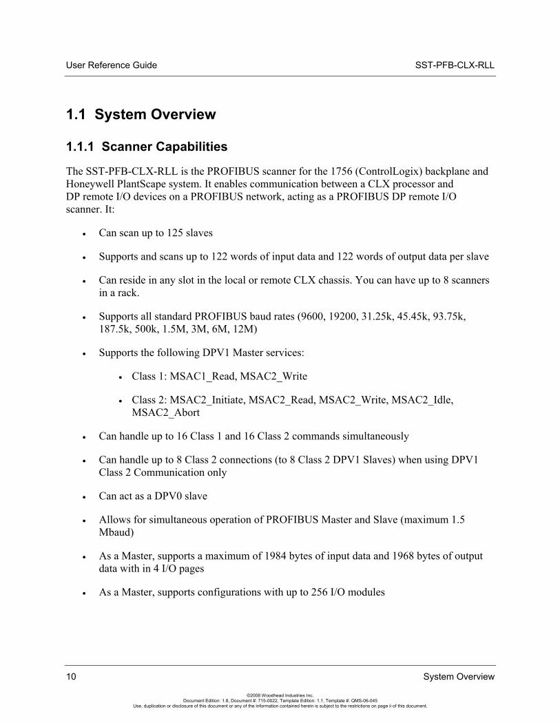
The SST-PFB-CLX-RLL is the PROFIBUS scanner for the 1756 (ControlLogix) backplane and Honeywell PlantScape system. It enables communication between a CLX processor and DP remote I/O devices on a PROFIBUS network, acting as a PROFIBUS DP remote I/O scanner. It:
• Can scan up to 125 slaves
• Supports and scans up to 122 words of input data and 122 words of output data per slave
• Can reside in any slot in the local or remote CLX chassis. You can have up to 8 scanners in a rack.
• Supports all standard PROFIBUS baud rates (9600, 19200, 31.25k, 45.45k, 93.75k, 187.5k, 500k, 1.5M, 3M, 6M, 12M)
• Supports the following DPV1 Master services:
• Class 1: MSAC1_Read, MSAC2_Write
• Class 2: MSAC2_Initiate, MSAC2_Read, MSAC2_Write, MSAC2_Idle, MSAC2_Abort
• Can handle up to 16 Class 1 and 16 Class 2 commands simultaneously
• Can handle up to 8 Class 2 connections (to 8 Class 2 DPV1 Slaves) when using DPV1 Class 2 Communication only
• Can act as a DPV0 slave
• Allows for simultaneous operation of PROFIBUS Master and Slave (maximum 1.5 Mbaud)
• As a Master, supports a maximum of 1984 bytes of input data and 1968 bytes of output data with in 4 I/O pages
• As a Master, supports configurations with up to 256 I/O modules
SST-PFB-CLX-RLL User Reference Guide
System Overview 11
©2008 Woodhead Industries Inc. Document Edition: 1.8, Document #: 715-0022, Template Edition: 1.1, Template #: QMS-06-045
Use, duplication or disclosure of this document or any of the information contained herein is subject to the restrictions on page ii of this document.
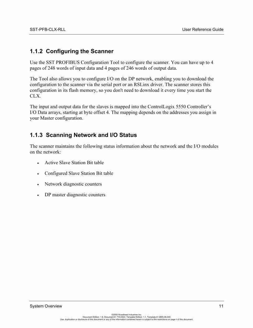
1.1.2 Configuring the Scanner
Use the SST PROFIBUS Configuration Tool to configure the scanner. You can have up to 4 pages of 248 words of input data and 4 pages of 246 words of output data.
The Tool also allows you to configure I/O on the DP network, enabling you to download the configuration to the scanner via the serial port or an RSLinx driver. The scanner stores this configuration in its flash memory, so you don't need to download it every time you start the CLX.
The input and output data for the slaves is mapped into the ControlLogix 5550 Controller’s I/O Data arrays, starting at byte offset 4. The mapping depends on the addresses you assign in your Master configuration.
1.1.3 Scanning Network and I/O Status
The scanner maintains the following status information about the network and the I/O modules on the network:
• Active Slave Station Bit table
• Configured Slave Station Bit table
• Network diagnostic counters
• DP master diagnostic counters
User Reference Guide SST-PFB-CLX-RLL
12 System Overview
©2008 Woodhead Industries Inc. Document Edition: 1.8, Document #: 715-0022, Template Edition: 1.1, Template #: QMS-06-045
Use, duplication or disclosure of this document or any of the information contained herein is subject to the restrictions on page ii of this document.
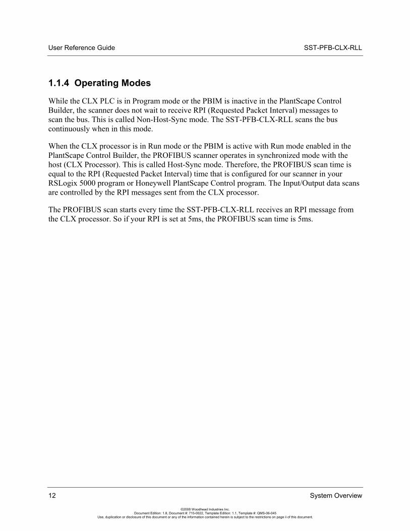
1.1.4 Operating Modes
While the CLX PLC is in Program mode or the PBIM is inactive in the PlantScape Control Builder, the scanner does not wait to receive RPI (Requested Packet Interval) messages to scan the bus. This is called Non-Host-Sync mode. The SST-PFB-CLX-RLL scans the bus continuously when in this mode.
When the CLX processor is in Run mode or the PBIM is active with Run mode enabled in the PlantScape Control Builder, the PROFIBUS scanner operates in synchronized mode with the host (CLX Processor). This is called Host-Sync mode. Therefore, the PROFIBUS scan time is equal to the RPI (Requested Packet Interval) time that is configured for our scanner in your RSLogix 5000 program or Honeywell PlantScape Control program. The Input/Output data scans are controlled by the RPI messages sent from the CLX processor.
The PROFIBUS scan starts every time the SST-PFB-CLX-RLL receives an RPI message from the CLX processor. So if your RPI is set at 5ms, the PROFIBUS scan time is 5ms.
SST-PFB-CLX-RLL User Reference Guide
Hardware Overview 13
©2008 Woodhead Industries Inc. Document Edition: 1.8, Document #: 715-0022, Template Edition: 1.1, Template #: QMS-06-045
Use, duplication or disclosure of this document or any of the information contained herein is subject to the restrictions on page ii of this document.
2 Hardware Overview
Chapter Sections:
• Hardware Features
User Reference Guide SST-PFB-CLX-RLL
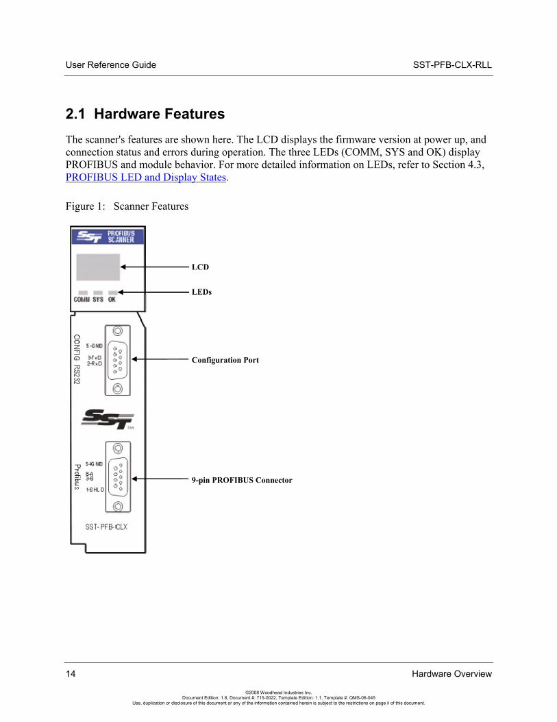
2.1 Hardware Features The scanner's features are shown here. The LCD displays the firmware version at power up, and connection status and errors during operation. The three LEDs (COMM, SYS and OK) display PROFIBUS and module behavior. For more detailed information on LEDs, refer to Section 4.3, PROFIBUS LED and Display States.
Figure 1: Scanner Features
LCD
LEDs
9-pin PROFIBUS Connector
Configuration Port
14 Hardware Overview
©2008 Woodhead Industries Inc. Document Edition: 1.8, Document #: 715-0022, Template Edition: 1.1, Template #: QMS-06-045
Use, duplication or disclosure of this document or any of the information contained herein is subject to the restrictions on page ii of this document.
SST-PFB-CLX-RLL User Reference Guide
Hardware Overview 15
©2008 Woodhead Industries Inc. Document Edition: 1.8, Document #: 715-0022, Template Edition: 1.1, Template #: QMS-06-045
Use, duplication or disclosure of this document or any of the information contained herein is subject to the restrictions on page ii of this document.
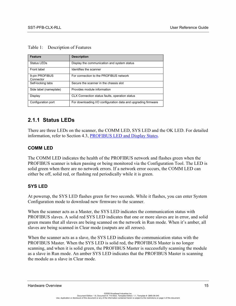
Table 1: Description of Features
Feature Description
Status LEDs Display the communication and system status
Front label Identifies the scanner
9-pin PROFIBUS Connector
For connection to the PROFIBUS network
Self-locking tabs Secure the scanner in the chassis slot
Side label (nameplate) Provides module information
Display CLX Connection status faults, operation status
Configuration port For downloading I/O configuration data and upgrading firmware
2.1.1 Status LEDs
There are three LEDs on the scanner, the COMM LED, SYS LED and the OK LED. For detailed information, refer to Section 4.3, PROFIBUS LED and Display States.
COMM LED
The COMM LED indicates the health of the PROFIBUS network and flashes green when the PROFIBUS scanner is token passing or being monitored via the Configuration Tool. The LED is solid green when there are no network errors. If a network error occurs, the COMM LED can either be off, solid red, or flashing red periodically while it is green.
SYS LED
At powerup, the SYS LED flashes green for two seconds. While it flashes, you can enter System Configuration mode to download new firmware to the scanner.
When the scanner acts as a Master, the SYS LED indicates the communication status with PROFIBUS slaves. A solid red SYS LED indicates that one or more slaves are in error, and solid green means that all slaves are being scanned on the network in Run mode. When it’s amber, all slaves are being scanned in Clear mode (outputs are all zeroes).
When the scanner acts as a slave, the SYS LED indicates the communication status with the PROFIBUS Master. When the SYS LED is solid red, the PROFIBUS Master is no longer scanning, and when it is solid green, the PROFIBUS Master is successfully scanning the module as a slave in Run mode. An amber SYS LED indicates that the PROFIBUS Master is scanning the module as a slave in Clear mode.
User Reference Guide SST-PFB-CLX-RLL
16 Hardware Overview
©2008 Woodhead Industries Inc. Document Edition: 1.8, Document #: 715-0022, Template Edition: 1.1, Template #: QMS-06-045
Use, duplication or disclosure of this document or any of the information contained herein is subject to the restrictions on page ii of this document.
OK LED
The OK LED indicates that initialization is complete and that the module is OK.
2.1.2 9-Pin PROFIBUS Connector
The 9-pin PROFIBUS Connector connects the scanner to the PROFIBUS network.
2.1.3 Configuration Port
Use the configuration port to download I/O configurations via the Configuration Tool or Hyperterminal and to upgrade scanner firmware.
SST-PFB-CLX-RLL User Reference Guide
Quick Start 17
©2008 Woodhead Industries Inc. Document Edition: 1.8, Document #: 715-0022, Template Edition: 1.1, Template #: QMS-06-045
Use, duplication or disclosure of this document or any of the information contained herein is subject to the restrictions on page ii of this document.
3 Quick Start
Chapter Sections:
• Purpose
• Equipment and Tools
• Package Contents
• Power Requirements
• Procedures
User Reference Guide SST-PFB-CLX-RLL
18 Quick Start
©2008 Woodhead Industries Inc. Document Edition: 1.8, Document #: 715-0022, Template Edition: 1.1, Template #: QMS-06-045
Use, duplication or disclosure of this document or any of the information contained herein is subject to the restrictions on page ii of this document.
3.1 Purpose Although this section does not include detailed information in its procedures, other chapters are referenced where more information is available. These procedures are written with the assumption that you have a basic understanding of process control and are fully able to interpret the ladder logic instructions that control the applications.
3.2 Equipment and Tools Have the following tools and equipment ready:
• CLX programming equipment
• Sample RSLogix 5000 v.11 Ladder program (SSTPFBCLX_Preview_2_Example.ACD)
• Sample RSLogix 5000 v.11 Ladder Program (DPV1_Class1.ACD & DPV1_Class2.ACD)
• Sample RSLogix 5000 v.11 Ladder Program (sstpfbclx_IO_Expansion.ACD)
• SST PROFIBUS Configuration Tool
• Terminal Software (Optional)
• Null modem cable
• PROFIBUS cable to connect the scanner to the PROFIBUS network
• PROFIBUS DB-9 connector. Suggestion: Brad Harrison PA9D01-42.
3.3 Package Contents Unpack the SST-PFB-CLX-RLL scanner module. Make sure that the contents include:
• PROFIBUS scanner
• PDF version of this manual included on the CD
• Serial null modem cable for downloading I/O configurations
• CD with files for Windows NT/2000/XP installations
SST-PFB-CLX-RLL User Reference Guide
3.4 Power Requirements Review your system’s power requirements to see that your chassis supports placement of the scanner module.
Note The scanner consumes 850 mA @ 5VDC, 1.75 mA @ 24VDC.
For modular systems, calculate the total load on the system power supply using the procedure described in the CLX 5000 Modular Style Installation & Operation Manual, Allen-Bradley Publication 1747-6.2
3.5 Procedures The setup of the SST-PFB-CLX-RLL scanner is divided into two parts:
• Setting up the scanner
• Getting the scanner running
3.5.1 Setting up the Scanner
The following steps describe the SST-PFB-CLX-RLL scanner setup procedure:
1. Insert the scanner module into your 1756 CLX chassis.
2. Connect the scanner to the PROFIBUS devices using the appropriate cabling and termination. Refer to Section 4.2, PROFIBUS Wiring, for more detailed information.
3. From the CD, open the supplied sample RSLogix 5000 Ladder program that you need to include with the rest of your control program to operate the scanner.
Note You may need to change the rack size and scanner location in the I/O configuration. Changing the slot location will update the existing controller tags.
Quick Start 19
©2008 Woodhead Industries Inc. Document Edition: 1.8, Document #: 715-0022, Template Edition: 1.1, Template #: QMS-06-045
Use, duplication or disclosure of this document or any of the information contained herein is subject to the restrictions on page ii of this document.
User Reference Guide SST-PFB-CLX-RLL
If you are using PlantScape, refer to Section 5.1.2, Configuring Through PlantScape Control Builder.
4. Set up your system's I/O configuration for the particular slot in which you installed the scanner. Refer to Section 5.1, Configuring the Scanner, for more information.
5. Save your program.
6. Apply power to the CLX.
7. Put the CLX PLC in Program mode and transfer the program to the CLX PLC. See your programming software manuals for details.
3.5.2 Getting the Scanner Running
The following steps describe how to install and set up the PFB-CLX-RLL scanner:
1. Install version 2.9 or higher of the SST PROFIBUS Configuration Tool.
Note Ensure that you uninstall any previous PROFIBUS installation and reboot your PC before installing a new version of the software.
Refer to Section 5.1.1, Configuring Through RSLogix 5000, for more detailed information. If you are using PlantScape, refer to refer to Section 5.1.2, Configuring Through PlantScape Control Builder.
2. Run the setup.exe file from the supplied Windows NT/2000/XP/Server 2003 installation CD. This installation script has an option to install a set of tools for use with SST PROFIBUS backplane modules. The SST-PFB-CLX-RLL scanner is a backplane module and this option should be used to install the Configuration Tool and associated software.
3. Open the SST PROFIBUS Configuration Tool window by selecting: Start Menu > SST PROFIBUS Configuration.
4. Select File > New.
5. In the PROFIBUS Device library (left-most pane), select and drag the SST-PFB-CLX-RLL master into the Network view (right-most pane) to add it.
20 Quick Start
©2008 Woodhead Industries Inc. Document Edition: 1.8, Document #: 715-0022, Template Edition: 1.1, Template #: QMS-06-045
Use, duplication or disclosure of this document or any of the information contained herein is subject to the restrictions on page ii of this document.
SST-PFB-CLX-RLL User Reference Guide
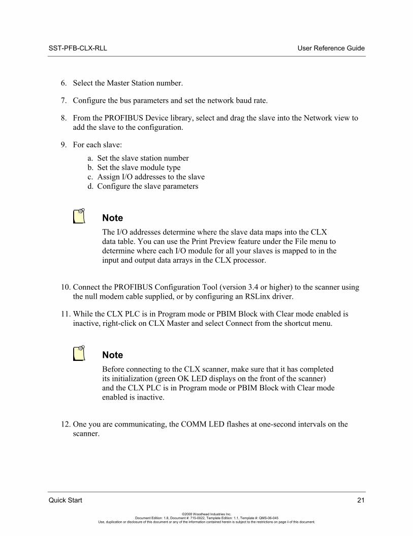
6. Select the Master Station number.
7. Configure the bus parameters and set the network baud rate.
8. From the PROFIBUS Device library, select and drag the slave into the Network view to add the slave to the configuration.
9. For each slave:
a. Set the slave station number b. Set the slave module type c. Assign I/O addresses to the slave d. Configure the slave parameters
Note The I/O addresses determine where the slave data maps into the CLX data table. You can use the Print Preview feature under the File menu to determine where each I/O module for all your slaves is mapped to in the input and output data arrays in the CLX processor.
10. Connect the PROFIBUS Configuration Tool (version 3.4 or higher) to the scanner using the null modem cable supplied, or by configuring an RSLinx driver.
11. While the CLX PLC is in Program mode or PBIM Block with Clear mode enabled is inactive, right-click on CLX Master and select Connect from the shortcut menu.
Note Before connecting to the CLX scanner, make sure that it has completed its initialization (green OK LED displays on the front of the scanner) and the CLX PLC is in Program mode or PBIM Block with Clear mode enabled is inactive.
12. One you are communicating, the COMM LED flashes at one-second intervals on the scanner.
Quick Start 21
©2008 Woodhead Industries Inc. Document Edition: 1.8, Document #: 715-0022, Template Edition: 1.1, Template #: QMS-06-045
Use, duplication or disclosure of this document or any of the information contained herein is subject to the restrictions on page ii of this document.
User Reference Guide SST-PFB-CLX-RLL
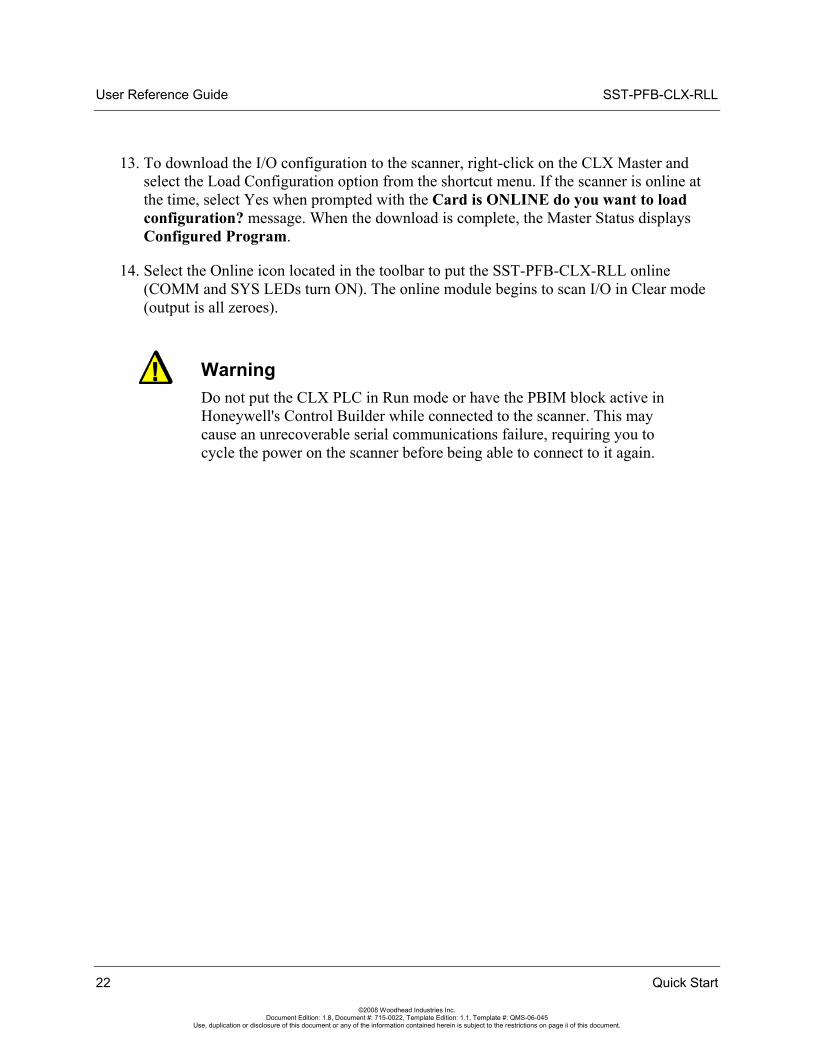
13. To download the I/O configuration to the scanner, right-click on the CLX Master and select the Load Configuration option from the shortcut menu. If the scanner is online at the time, select Yes when prompted with the Card is ONLINE do you want to load configuration? message. When the download is complete, the Master Status displays Configured Program.
14. Select the Online icon located in the toolbar to put the SST-PFB-CLX-RLL online (COMM and SYS LEDs turn ON). The online module begins to scan I/O in Clear mode (output is all zeroes).
Warning Do not put the CLX PLC in Run mode or have the PBIM block active in Honeywell's Control Builder while connected to the scanner. This may cause an unrecoverable serial communications failure, requiring you to cycle the power on the scanner before being able to connect to it again.
22 Quick Start
©2008 Woodhead Industries Inc. Document Edition: 1.8, Document #: 715-0022, Template Edition: 1.1, Template #: QMS-06-045
Use, duplication or disclosure of this document or any of the information contained herein is subject to the restrictions on page ii of this document.
SST-PFB-CLX-RLL User Reference Guide
Installing the SST-PFB-CLX-RLL Scanner 23
©2008 Woodhead Industries Inc. Document Edition: 1.8, Document #: 715-0022, Template Edition: 1.1, Template #: QMS-06-045
Use, duplication or disclosure of this document or any of the information contained herein is subject to the restrictions on page ii of this document.
4 Installing the SST-PFB-CLX-RLL Scanner
Chapter Sections:
• Installing the Scanner Module
• PROFIBUS Wiring
• PROFIBUS LED and Display States
User Reference Guide SST-PFB-CLX-RLL
24 Installing the SST-PFB-CLX-RLL Scanner
©2008 Woodhead Industries Inc. Document Edition: 1.8, Document #: 715-0022, Template Edition: 1.1, Template #: QMS-06-045
Use, duplication or disclosure of this document or any of the information contained herein is subject to the restrictions on page ii of this document.
4.1 Installing the Scanner Module
4.1.1 Installation Procedure
The following procedure describes how to install the scanner module:
1. You can, but do not necessarily need to disconnect the power, as the scanner supports insertion under power.
2. Using the chassis card guides, align the full-sized circuit board.
3. Slide the module into the chassis until the top and bottom latches catch.
4. Attach the PROFIBUS cable.
5. Turn on connector termination as required.
6. Route the cable down and away from the scanner.
4.1.2 Removal Procedure
The following procedure describes how to uninstall the scanner module:
1. You can, but do not necessarily need to disconnect the power, as the scanner supports removal under power.
2. Remove all cabling from the scanner.
3. Press the releases at the top and bottom of the module and slide the module out of the module slot.
SST-PFB-CLX-RLL User Reference Guide
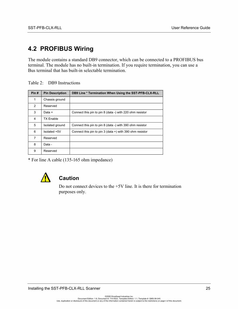
4.2 PROFIBUS Wiring The module contains a standard DB9 connector, which can be connected to a PROFIBUS bus terminal. The module has no built-in termination. If you require termination, you can use a Bus terminal that has built-in selectable termination.
Table 2: DB9 Instructions
Pin # Pin Description DB9 Line * Termination When Using the SST-PFB-CLX-RLL
1 Chassis ground
2 Reserved
3 Data + Connect this pin to pin 8 (data -) with 220 ohm resistor
4 TX Enable
5 Isolated ground Connect this pin to pin 8 (data -) with 390 ohm resistor
6 Isolated +5V Connect this pin to pin 3 (data +) with 390 ohm resistor
7 Reserved
8 Data -
9 Reserved
* For line A cable (135-165 ohm impedance)
Caution Do not connect devices to the +5V line. It is there for termination purposes only.
Installing the SST-PFB-CLX-RLL Scanner 25
©2008 Woodhead Industries Inc. Document Edition: 1.8, Document #: 715-0022, Template Edition: 1.1, Template #: QMS-06-045
Use, duplication or disclosure of this document or any of the information contained herein is subject to the restrictions on page ii of this document.
User Reference Guide SST-PFB-CLX-RLL
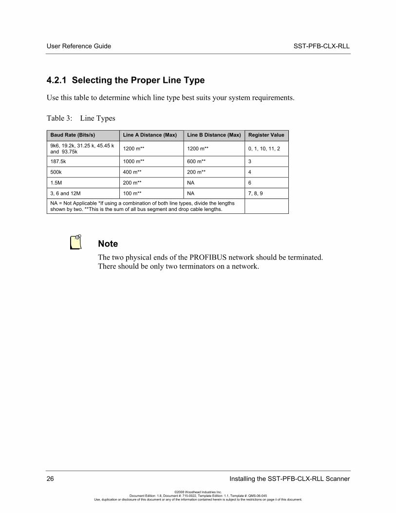
4.2.1 Selecting the Proper Line Type
Use this table to determine which line type best suits your system requirements.
Table 3: Line Types
Baud Rate (Bits/s) Line A Distance (Max) Line B Distance (Max) Register Value
9k6, 19.2k, 31.25 k, 45.45 k and 93.75k 1200 m** 1200 m** 0, 1, 10, 11, 2
187.5k 1000 m** 600 m** 3
500k 400 m** 200 m** 4
1.5M 200 m** NA 6
3, 6 and 12M 100 m** NA 7, 8, 9
NA = Not Applicable *If using a combination of both line types, divide the lengths shown by two. **This is the sum of all bus segment and drop cable lengths.
Note The two physical ends of the PROFIBUS network should be terminated. There should be only two terminators on a network.
26 Installing the SST-PFB-CLX-RLL Scanner
©2008 Woodhead Industries Inc. Document Edition: 1.8, Document #: 715-0022, Template Edition: 1.1, Template #: QMS-06-045
Use, duplication or disclosure of this document or any of the information contained herein is subject to the restrictions on page ii of this document.
SST-PFB-CLX-RLL User Reference Guide
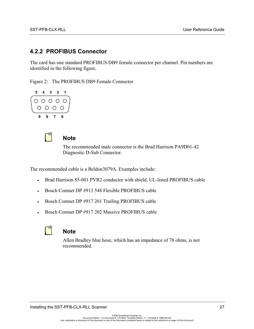
4.2.2 PROFIBUS Connector
The card has one standard PROFIBUS DB9 female connector per channel. Pin numbers are identified in the following figure.
Figure 2: The PROFIBUS DB9 Female Connector
Note The recommended male connector is the Brad Harrison PA9D01-42 Diagnostic D-Sub Connector.
The recommended cable is a Beldon3079A. Examples include:
• Brad Harrison 85-001 PVR2 conductor with shield, UL-listed PROFIBUS cable
• Bosch Comnet DP #913 548 Flexible PROFIBUS cable
• Bosch Comnet DP #917 201 Trailing PROFIBUS cable
• Bosch Comnet DP #917 202 Massive PROFIBUS cable
Note Allen Bradley blue hose, which has an impedance of 78 ohms, is not recommended.
Installing the SST-PFB-CLX-RLL Scanner 27
©2008 Woodhead Industries Inc. Document Edition: 1.8, Document #: 715-0022, Template Edition: 1.1, Template #: QMS-06-045
Use, duplication or disclosure of this document or any of the information contained herein is subject to the restrictions on page ii of this document.
User Reference Guide SST-PFB-CLX-RLL
28 Installing the SST-PFB-CLX-RLL Scanner
©2008 Woodhead Industries Inc. Document Edition: 1.8, Document #: 715-0022, Template Edition: 1.1, Template #: QMS-06-045
Use, duplication or disclosure of this document or any of the information contained herein is subject to the restrictions on page ii of this document.
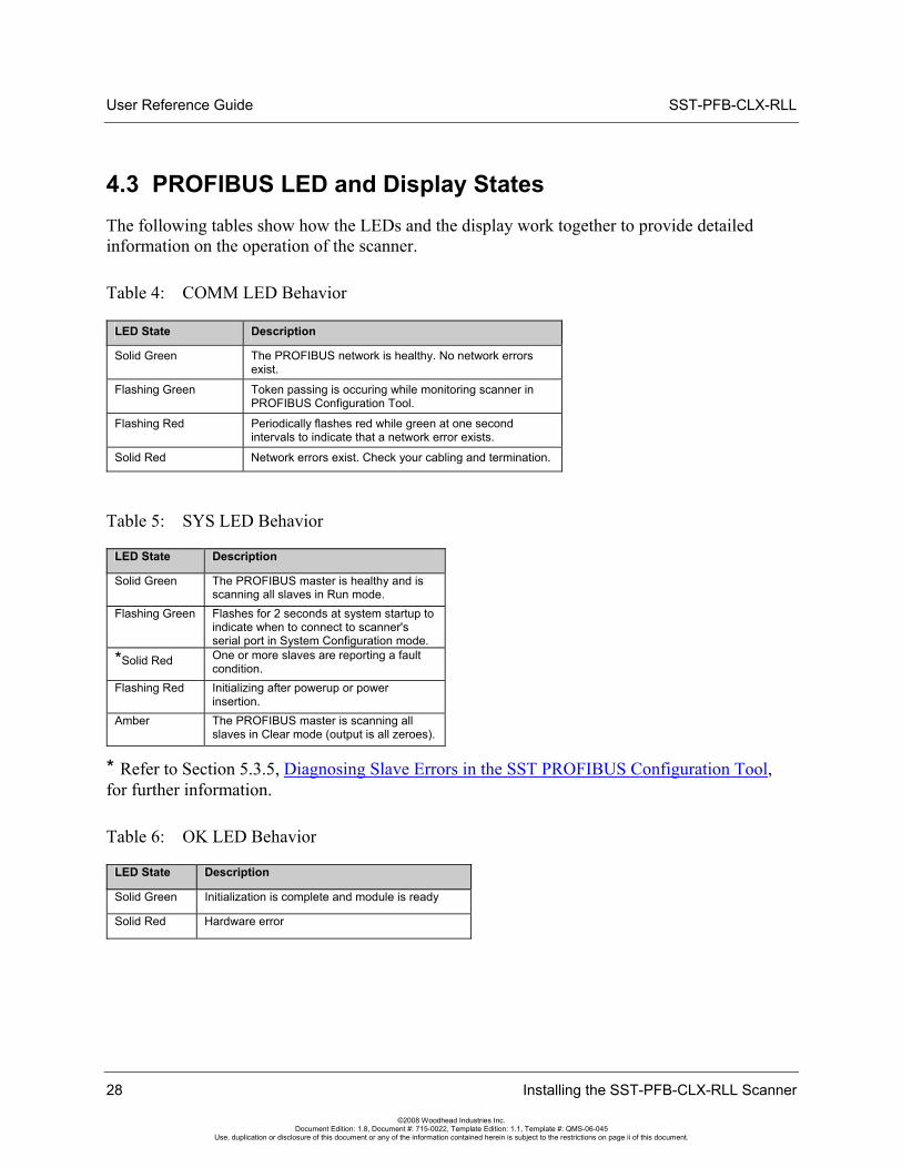
4.3 PROFIBUS LED and Display States The following tables show how the LEDs and the display work together to provide detailed information on the operation of the scanner.
Table 4: COMM LED Behavior
LED State Description
Solid Green The PROFIBUS network is healthy. No network errors exist.
Flashing Green Token passing is occuring while monitoring scanner in PROFIBUS Configuration Tool.
Flashing Red Periodically flashes red while green at one second intervals to indicate that a network error exists.
Solid Red Network errors exist. Check your cabling and termination.
Table 5: SYS LED Behavior
LED State Description
Solid Green The PROFIBUS master is healthy and is scanning all slaves in Run mode.
Flashing Green Flashes for 2 seconds at system startup to indicate when to connect to scanner's serial port in System Configuration mode.
*Solid Red One or more slaves are reporting a fault condition.
Flashing Red Initializing after powerup or power insertion.
Amber The PROFIBUS master is scanning all slaves in Clear mode (output is all zeroes).
* Refer to Section 5.3.5, Diagnosing Slave Errors in the SST PROFIBUS Configuration Tool, for further information.
Table 6: OK LED Behavior
LED State Description
Solid Green Initialization is complete and module is ready
Solid Red Hardware error
SST-PFB-CLX-RLL User Reference Guide
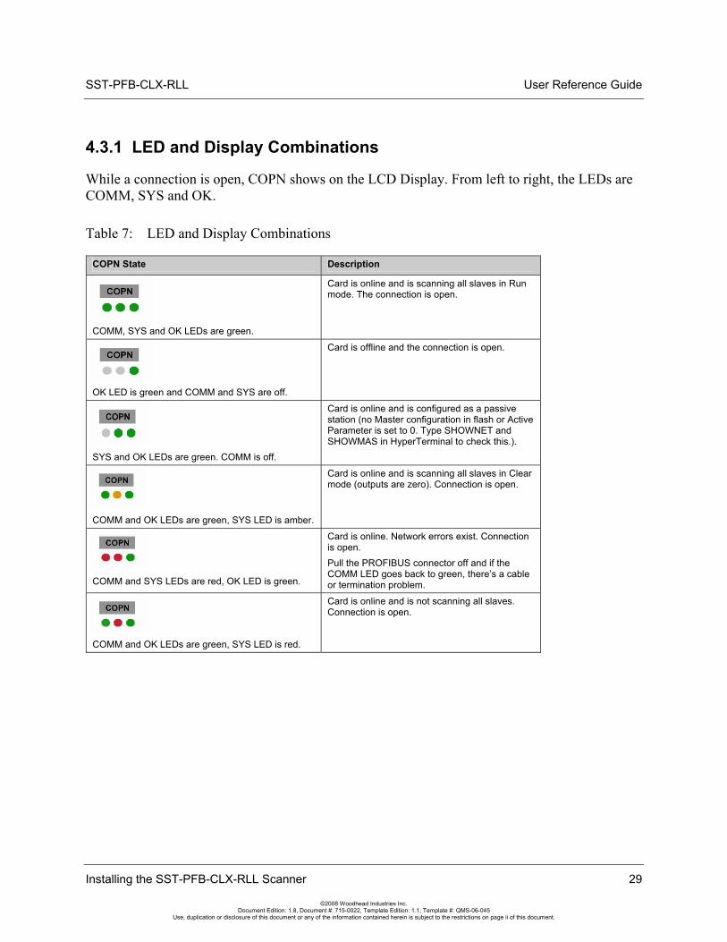
4.3.1 LED and Display Combinations
While a connection is open, COPN shows on the LCD Display. From left to right, the LEDs are COMM, SYS and OK.
Table 7: LED and Display Combinations
COPN State Description
COMM, SYS and OK LEDs are green.
Card is online and is scanning all slaves in Run mode. The connection is open.
OK LED is green and COMM and SYS are off.
Card is offline and the connection is open.
SYS and OK LEDs are green. COMM is off.
Card is online and is configured as a passive station (no Master configuration in flash or Active Parameter is set to 0. Type SHOWNET and SHOWMAS in HyperTerminal to check this.).
COMM and OK LEDs are green, SYS LED is amber.
Card is online and is scanning all slaves in Clear mode (outputs are zero). Connection is open.
COMM and SYS LEDs are red, OK LED is green.
Card is online. Network errors exist. Connection is open. Pull the PROFIBUS connector off and if the COMM LED goes back to green, there’s a cable or termination problem.
COMM and OK LEDs are green, SYS LED is red.
Card is online and is not scanning all slaves. Connection is open.
Installing the SST-PFB-CLX-RLL Scanner 29
©2008 Woodhead Industries Inc. Document Edition: 1.8, Document #: 715-0022, Template Edition: 1.1, Template #: QMS-06-045
Use, duplication or disclosure of this document or any of the information contained herein is subject to the restrictions on page ii of this document.
User Reference Guide SST-PFB-CLX-RLL
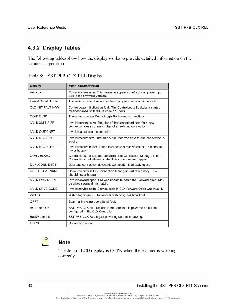
4.3.2 Display Tables
The following tables show how the display works to provide detailed information on the scanner’s operation:
Table 8: SST-PFB-CLX-RLL Display
Display Meaning/Description
Ver x.xx Power up message. This message appears briefly during power up. x.xx is the firmware version.
Invalid Serial Number The serial number has not yet been programmed on this module.
CLX INIT FALT 0xYY ControlLogix Initialization fault. The ControlLogix Backplane startup routines failed, with failure code YY (hex).
CONNCLSD There are no open ControlLogix Backplane connections.
NVLD XMIT SIZE Invalid transmit size. The size of the transmitted data for a new connection does not match that of an existing connection.
NVLD OUT CNPT Invalid output connection point.
NVLD RCV SIZE Invalid receive size. The size of the received data for the connection is invalid.
NVLD RCV BUFF Invalid receive buffer. Failed to allocate a receive buffer. This should never happen.
CONN BLKED Connections blocked (not allowed). The Connection Manager is in a Connections not allowed state. This should never happen.
DUPLCONN DTCT Duplicate connection detected. Connection is already open.
RSRC ERR1 INCM Resource error # 1 in Connection Manager: Out of memory. This should never happen.
NVLD FWD OPEN Invalid forward open. CM was unable to parse the Forward open. May be a key segment mismatch.
NVLD SRVC CODE Invalid service code. Service code in CLX Forward Open was invalid.
WDOG Watchdog timeout. The module watchdog has timed out.
OFPT Scanner firmware operational fault.
BCKPlane OK SST-PFB-CLX-RLL resides in the rack that is powered on but not configured in the CLX Controller.
BackPlane Init SST-PFB-CLX-RLL is just powering up and initializing.
COPN Connection open.
Note The default LCD display is COPN when the scanner is working correctly.
30 Installing the SST-PFB-CLX-RLL Scanner
©2008 Woodhead Industries Inc. Document Edition: 1.8, Document #: 715-0022, Template Edition: 1.1, Template #: QMS-06-045
Use, duplication or disclosure of this document or any of the information contained herein is subject to the restrictions on page ii of this document.
SST-PFB-CLX-RLL User Reference Guide
Configuring and Programming the DP Master 31
©2008 Woodhead Industries Inc. Document Edition: 1.8, Document #: 715-0022, Template Edition: 1.1, Template #: QMS-06-045
Use, duplication or disclosure of this document or any of the information contained herein is subject to the restrictions on page ii of this document.
5 Configuring and Programming the DP Master
Chapter Sections:
• Configuring the Scanner
• Creating an I/O Configuration
• Downloading to the Scanner
• Troubleshooting
• Importing the DP Master Binary Configuration (.bss) Using the Configuration Tool
• Downloading the I/O Configuration to the Scanner Using HyperTerminal
• Errors
• Running the Scanner
• SST-PFB-CLX-RLL I/O and Status Images
• Making Changes to the CLX Configuration File while the PROFIBUS card is Online
User Reference Guide SST-PFB-CLX-RLL
5.1 Configuring the Scanner
5.1.1 Configuring Through RSLogix 5000
This procedure was tested with versions 11.0, 12.0, 13.0 and 15.0 of RSLogix 5000.
Note When you are configuring the scanner, ensure that the CLX is in Program mode.
To configure through RSLogix 5000, follow these steps:
1. Create a new program offline.
2. Select the 1756 CLX ControlLogix Controller as the Controller type.
3. Select the correct Chassis type that you are using from the list.
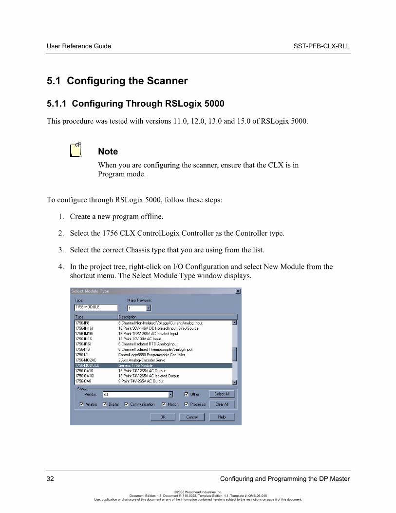
4. In the project tree, right-click on I/O Configuration and select New Module from the shortcut menu. The Select Module Type window displays.
32 Configuring and Programming the DP Master
©2008 Woodhead Industries Inc. Document Edition: 1.8, Document #: 715-0022, Template Edition: 1.1, Template #: QMS-06-045
Use, duplication or disclosure of this document or any of the information contained herein is subject to the restrictions on page ii of this document.
SST-PFB-CLX-RLL User Reference Guide
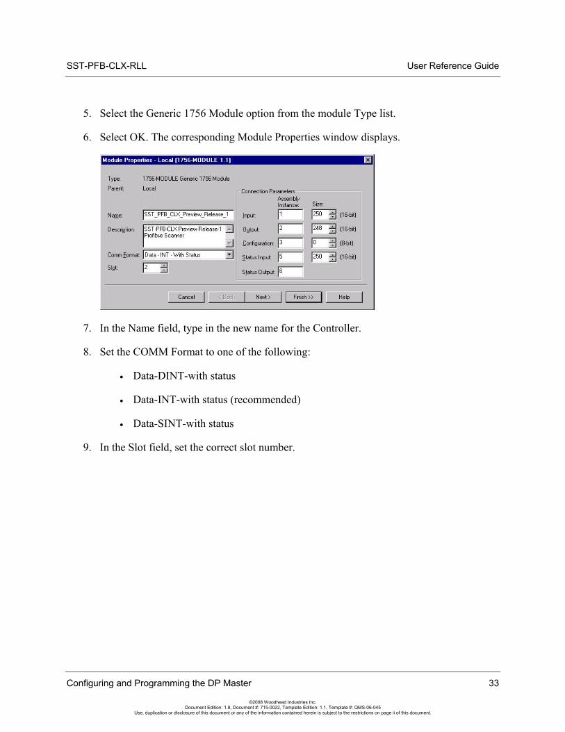
5. Select the Generic 1756 Module option from the module Type list.
6. Select OK. The corresponding Module Properties window displays.
7. In the Name field, type in the new name for the Controller.
8. Set the COMM Format to one of the following:
• Data-DINT-with status
• Data-INT-with status (recommended)
• Data-SINT-with status
9. In the Slot field, set the correct slot number.
Configuring and Programming the DP Master 33
©2008 Woodhead Industries Inc. Document Edition: 1.8, Document #: 715-0022, Template Edition: 1.1, Template #: QMS-06-045
Use, duplication or disclosure of this document or any of the information contained herein is subject to the restrictions on page ii of this document.

User Reference Guide SST-PFB-CLX-RLL
10. From the Connection Parameters frame, set the following values:
• Input - Assembly Instance to 1 and Size to 250 16-bit elements
• Output - Assembly Instance to 2 and a Size to 248 16-bit elements
• Configuration - Assembly Instance to 3 and Size to 0 (zero)
• Status Input - Assembly Instance to 5 and a Size to 250 elements
• Status Output - Assembly Instance to 6
Note When using the scanner as a slave only, the Configuration Size should be set to 24.
11. Select Next >. The corresponding Modules Properties window displays.
12. Set the Requested Packet Interval (RPI) accordingly. The RPI value must not be any lower than 2 times the estimated PROFIBUS typical scan time, and should not be set to less than 3ms. For example, if your PROFIBUS typical scan time is 1.5ms (@12MB), then you must use 3ms or higher for the RPI value.
The estimated PROFIBUS typical scan time can be generated by the Configuration Tool once the PFB network has been created. To find the typical scan time, right-click on the CLX Master in the Tool and select Properties. Next, click the Parameters tab. The typical cycle time displays in microseconds in the upper-left corner. Refer to Section 5.2, Creating an I/O Configuration, for more information on using the Configuration Tool.
13. Select Finish >> to save the configuration.
34 Configuring and Programming the DP Master
©2008 Woodhead Industries Inc. Document Edition: 1.8, Document #: 715-0022, Template Edition: 1.1, Template #: QMS-06-045
Use, duplication or disclosure of this document or any of the information contained herein is subject to the restrictions on page ii of this document.
SST-PFB-CLX-RLL User Reference Guide
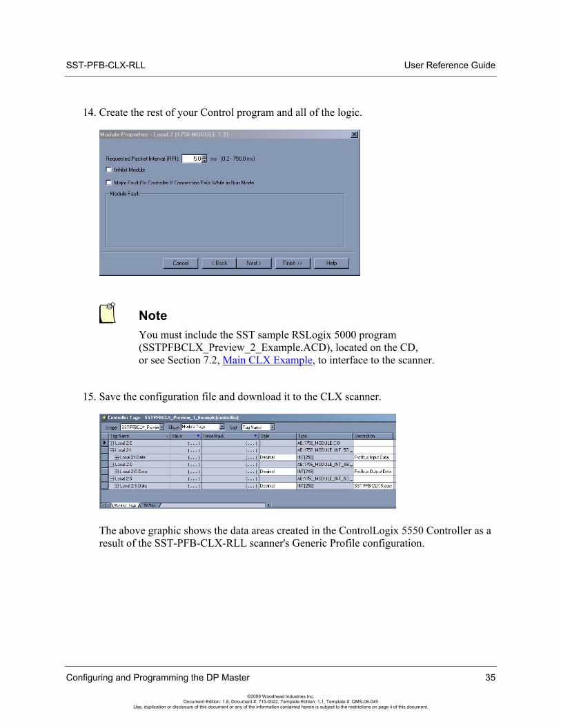
14. Create the rest of your Control program and all of the logic.
Note You must include the SST sample RSLogix 5000 program (SSTPFBCLX_Preview_2_Example.ACD), located on the CD, or see Section 7.2, Main CLX Example, to interface to the scanner.
15. Save the configuration file and download it to the CLX scanner.
The above graphic shows the data areas created in the ControlLogix 5550 Controller as a result of the SST-PFB-CLX-RLL scanner's Generic Profile configuration.
Configuring and Programming the DP Master 35
©2008 Woodhead Industries Inc. Document Edition: 1.8, Document #: 715-0022, Template Edition: 1.1, Template #: QMS-06-045
Use, duplication or disclosure of this document or any of the information contained herein is subject to the restrictions on page ii of this document.
User Reference Guide SST-PFB-CLX-RLL
36 Configuring and Programming the DP Master
©2008 Woodhead Industries Inc. Document Edition: 1.8, Document #: 715-0022, Template Edition: 1.1, Template #: QMS-06-045
Use, duplication or disclosure of this document or any of the information contained herein is subject to the restrictions on page ii of this document.
5.1.2 Configuring Through PlantScape Control Builder
If you are using the PlantScape System, perform the following steps to configure the SST-PFB-CLX-RLL scanner:
1. Open the PlantScape Control Builder by navigating to Programs > PlantScape Engineering Tools > Control Builder.
2. Close one of the project windows that displays.
3. Select CPM block.
4. Select the Load with Contents option from the Tools menu.
5. Select the Continue button.
6. Select the Monitoring tab located on the bottom of the Project window.
7. Select CEE.
8. From the Operate menu, select Activate.
9. From the sub-menu, select the This CEE and its 10M and CM's option.
10. Select YES in the Change State dialog box. This procedure places the processor in Run mode and the SST-PFB-CLX-RLL scanner online and in Run mode. For detailed information, refer to Honeywell's PlantScape PROFIBUS Implementation guide.
SST-PFB-CLX-RLL User Reference Guide
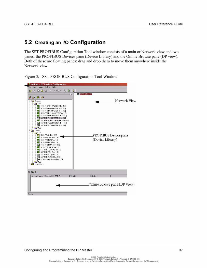
5.2 Creating an I/O Configuration The SST PROFIBUS Configuration Tool window consists of a main or Network view and two panes: the PROFIBUS Devices pane (Device Library) and the Online Browse pane (DP view). Both of these are floating panes; drag and drop them to move them anywhere inside the Network view.
Figure 3: SST PROFIBUS Configuration Tool Window
Configuring and Programming the DP Master 37
©2008 Woodhead Industries Inc. Document Edition: 1.8, Document #: 715-0022, Template Edition: 1.1, Template #: QMS-06-045
Use, duplication or disclosure of this document or any of the information contained herein is subject to the restrictions on page ii of this document.
User Reference Guide SST-PFB-CLX-RLL
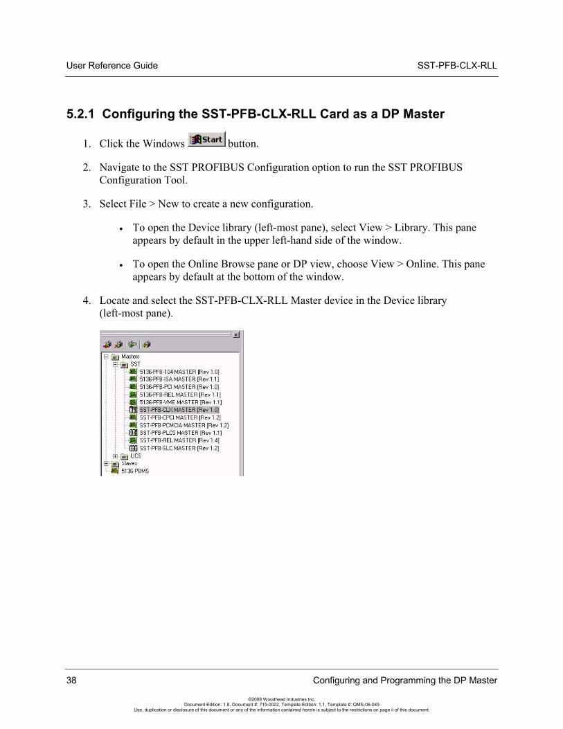
5.2.1 Configuring the SST-PFB-CLX-RLL Card as a DP Master
1. Click the Windows button.
2. Navigate to the SST PROFIBUS Configuration option to run the SST PROFIBUS Configuration Tool.
3. Select File > New to create a new configuration.
• To open the Device library (left-most pane), select View > Library. This pane appears by default in the upper left-hand side of the window.
• To open the Online Browse pane or DP view, choose View > Online. This pane appears by default at the bottom of the window.
4. Locate and select the SST-PFB-CLX-RLL Master device in the Device library (left-most pane).
38 Configuring and Programming the DP Master
©2008 Woodhead Industries Inc. Document Edition: 1.8, Document #: 715-0022, Template Edition: 1.1, Template #: QMS-06-045
Use, duplication or disclosure of this document or any of the information contained herein is subject to the restrictions on page ii of this document.
SST-PFB-CLX-RLL User Reference Guide
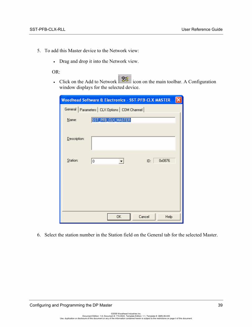
5. To add this Master device to the Network view:
• Drag and drop it into the Network view.
OR:
• Click on the Add to Network icon on the main toolbar. A Configuration window displays for the selected device.
6. Select the station number in the Station field on the General tab for the selected Master.
Configuring and Programming the DP Master 39
©2008 Woodhead Industries Inc. Document Edition: 1.8, Document #: 715-0022, Template Edition: 1.1, Template #: QMS-06-045
Use, duplication or disclosure of this document or any of the information contained herein is subject to the restrictions on page ii of this document.
User Reference Guide SST-PFB-CLX-RLL
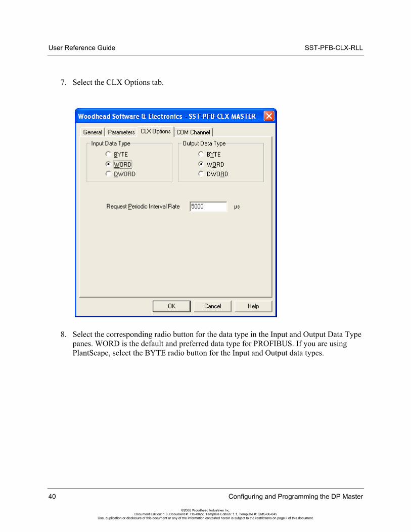
7. Select the CLX Options tab.
8. Select the corresponding radio button for the data type in the Input and Output Data Type panes. WORD is the default and preferred data type for PROFIBUS. If you are using PlantScape, select the BYTE radio button for the Input and Output data types.
40 Configuring and Programming the DP Master
©2008 Woodhead Industries Inc. Document Edition: 1.8, Document #: 715-0022, Template Edition: 1.1, Template #: QMS-06-045
Use, duplication or disclosure of this document or any of the information contained herein is subject to the restrictions on page ii of this document.
SST-PFB-CLX-RLL User Reference Guide
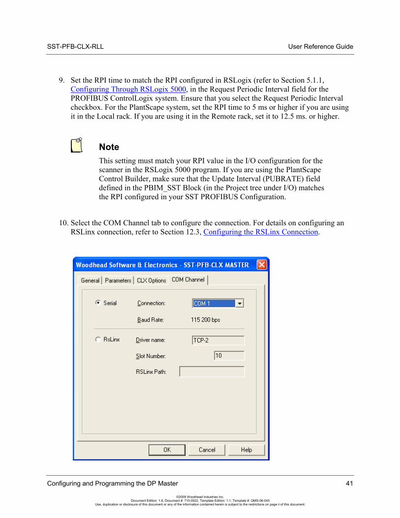
9. Set the RPI time to match the RPI configured in RSLogix (refer to Section 5.1.1, Configuring Through RSLogix 5000, in the Request Periodic Interval field for the PROFIBUS ControlLogix system. Ensure that you select the Request Periodic Interval checkbox. For the PlantScape system, set the RPI time to 5 ms or higher if you are using it in the Local rack. If you are using it in the Remote rack, set it to 12.5 ms. or higher.
Note This setting must match your RPI value in the I/O configuration for the scanner in the RSLogix 5000 program. If you are using the PlantScape Control Builder, make sure that the Update Interval (PUBRATE) field defined in the PBIM_SST Block (in the Project tree under I/O) matches the RPI configured in your SST PROFIBUS Configuration.
10. Select the COM Channel tab to configure the connection. For details on configuring an RSLinx connection, refer to Section 12.3, Configuring the RSLinx Connection.
Configuring and Programming the DP Master 41
©2008 Woodhead Industries Inc. Document Edition: 1.8, Document #: 715-0022, Template Edition: 1.1, Template #: QMS-06-045
Use, duplication or disclosure of this document or any of the information contained herein is subject to the restrictions on page ii of this document.
User Reference Guide SST-PFB-CLX-RLL
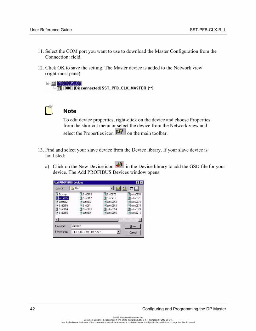
11. Select the COM port you want to use to download the Master Configuration from the Connection: field.
12. Click OK to save the setting. The Master device is added to the Network view (right-most pane).
Note To edit device properties, right-click on the device and choose Properties from the shortcut menu or select the device from the Network view and select the Properties icon on the main toolbar.
13. Find and select your slave device from the Device library. If your slave device is not listed:
a) Click on the New Device icon in the Device library to add the GSD file for your device. The Add PROFIBUS Devices window opens.
42 Configuring and Programming the DP Master
©2008 Woodhead Industries Inc. Document Edition: 1.8, Document #: 715-0022, Template Edition: 1.1, Template #: QMS-06-045
Use, duplication or disclosure of this document or any of the information contained herein is subject to the restrictions on page ii of this document.
SST-PFB-CLX-RLL User Reference Guide
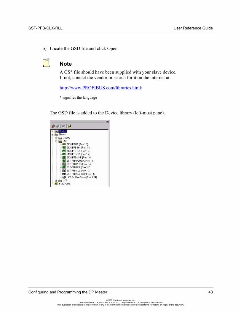
b) Locate the GSD file and click Open.
Note A GS* file should have been supplied with your slave device. If not, contact the vendor or search for it on the internet at:
Configuring and Programming the DP Master 43
©2008 Woodhead Industries Inc. Document Edition: 1.8, Document #: 715-0022, Template Edition: 1.1, Template #: QMS-06-045
Use, duplication or disclosure of this document or any of the information contained herein is subject to the restrictions on page ii of this document.
http://www.PROFIBUS.com/libraries.html/
* signifies the language
The GSD file is added to the Device library (left-most pane).
User Reference Guide SST-PFB-CLX-RLL
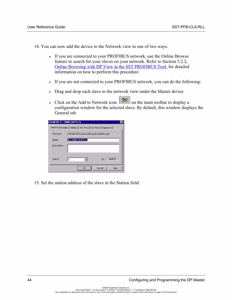
14. You can now add the device to the Network view in one of two ways.
• If you are connected to your PROFIBUS network, use the Online Browse feature to search for your slaves on your network. Refer to Section 5.2.2, Online Browsing with DP View in the SST PROFIBUS Tool, for detailed information on how to perform this procedure.
• If you are not connected to your PROFIBUS network, you can do the following:
• Drag and drop each slave to the network view under the Master device
• Click on the Add to Network icon on the main toolbar to display a configuration window for the selected slave. By default, this window displays the General tab.
15. Set the station address of the slave in the Station field.
44 Configuring and Programming the DP Master
©2008 Woodhead Industries Inc. Document Edition: 1.8, Document #: 715-0022, Template Edition: 1.1, Template #: QMS-06-045
Use, duplication or disclosure of this document or any of the information contained herein is subject to the restrictions on page ii of this document.
SST-PFB-CLX-RLL User Reference Guide
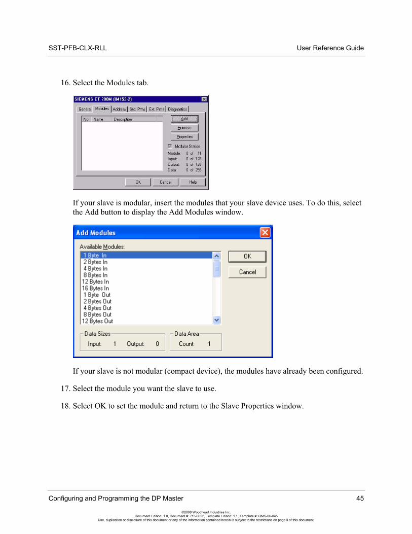
16. Select the Modules tab.
If your slave is modular, insert the modules that your slave device uses. To do this, select the Add button to display the Add Modules window.
If your slave is not modular (compact device), the modules have already been configured.
17. Select the module you want the slave to use.
18. Select OK to set the module and return to the Slave Properties window.
Configuring and Programming the DP Master 45
©2008 Woodhead Industries Inc. Document Edition: 1.8, Document #: 715-0022, Template Edition: 1.1, Template #: QMS-06-045
Use, duplication or disclosure of this document or any of the information contained herein is subject to the restrictions on page ii of this document.
User Reference Guide SST-PFB-CLX-RLL
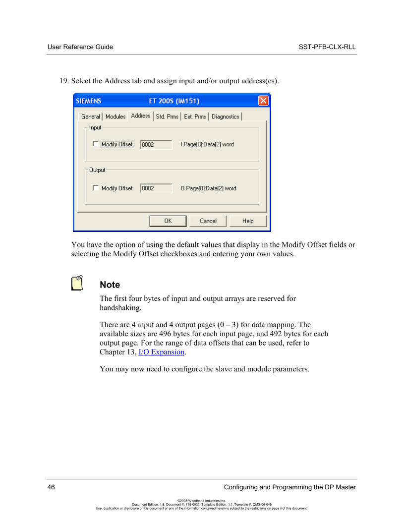
19. Select the Address tab and assign input and/or output address(es).
You have the option of using the default values that display in the Modify Offset fields or selecting the Modify Offset checkboxes and entering your own values.
46 Configuring and Programming the DP Master
©2008 Woodhead Industries Inc. Document Edition: 1.8, Document #: 715-0022, Template Edition: 1.1, Template #: QMS-06-045
Use, duplication or disclosure of this document or any of the information contained herein is subject to the restrictions on page ii of this document.
Note The first four bytes of input and output arrays are reserved for handshaking.
There are 4 input and 4 output pages (0 – 3) for data mapping. The available sizes are 496 bytes for each input page, and 492 bytes for each output page. For the range of data offsets that can be used, refer to Chapter 13, I/O Expansion.
You may now need to configure the slave and module parameters.
SST-PFB-CLX-RLL User Reference Guide
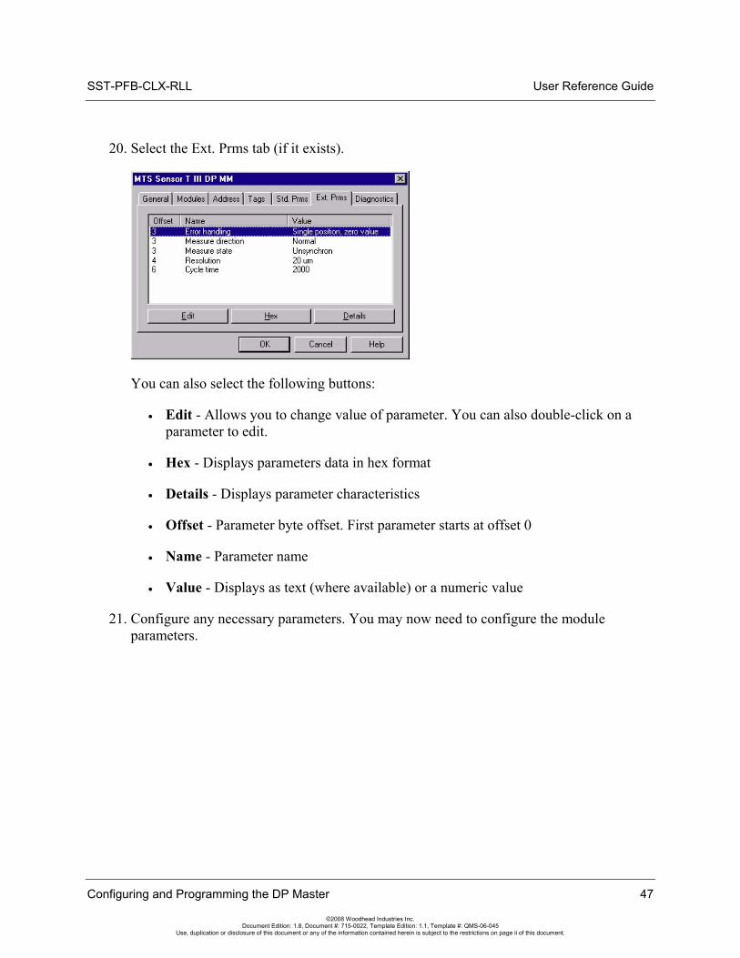
20. Select the Ext. Prms tab (if it exists).
You can also select the following buttons:
• Edit - Allows you to change value of parameter. You can also double-click on a parameter to edit.
• Hex - Displays parameters data in hex format
• Details - Displays parameter characteristics
• Offset - Parameter byte offset. First parameter starts at offset 0
• Name - Parameter name
• Value - Displays as text (where available) or a numeric value
21. Configure any necessary parameters. You may now need to configure the module parameters.
Configuring and Programming the DP Master 47
©2008 Woodhead Industries Inc. Document Edition: 1.8, Document #: 715-0022, Template Edition: 1.1, Template #: QMS-06-045
Use, duplication or disclosure of this document or any of the information contained herein is subject to the restrictions on page ii of this document.
User Reference Guide SST-PFB-CLX-RLL
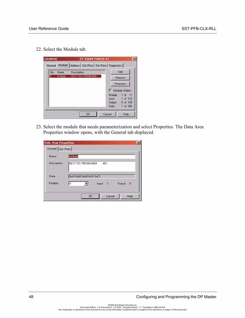
22. Select the Module tab.
23. Select the module that needs parameterization and select Properties. The Data Area Properties window opens, with the General tab displayed.
48 Configuring and Programming the DP Master
©2008 Woodhead Industries Inc. Document Edition: 1.8, Document #: 715-0022, Template Edition: 1.1, Template #: QMS-06-045
Use, duplication or disclosure of this document or any of the information contained herein is subject to the restrictions on page ii of this document.
SST-PFB-CLX-RLL User Reference Guide
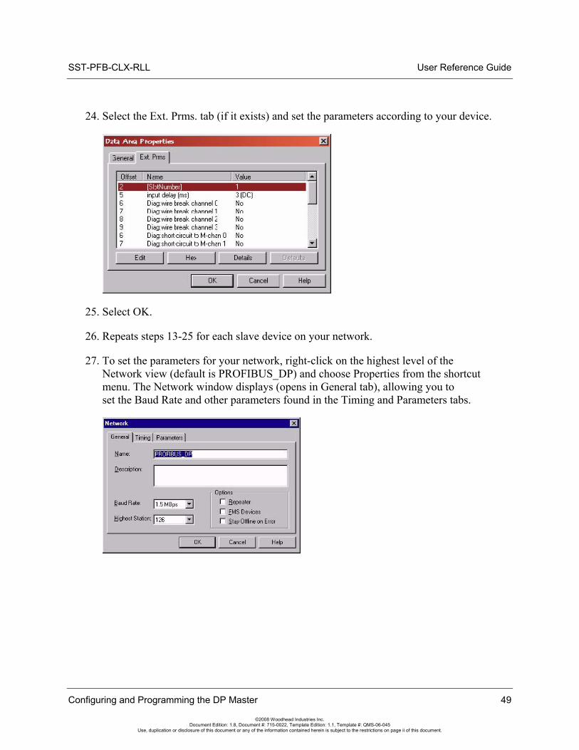
24. Select the Ext. Prms. tab (if it exists) and set the parameters according to your device.
25. Select OK.
26. Repeats steps 13-25 for each slave device on your network.
27. To set the parameters for your network, right-click on the highest level of the Network view (default is PROFIBUS_DP) and choose Properties from the shortcut menu. The Network window displays (opens in General tab), allowing you to set the Baud Rate and other parameters found in the Timing and Parameters tabs.
Configuring and Programming the DP Master 49
©2008 Woodhead Industries Inc. Document Edition: 1.8, Document #: 715-0022, Template Edition: 1.1, Template #: QMS-06-045
Use, duplication or disclosure of this document or any of the information contained herein is subject to the restrictions on page ii of this document.
User Reference Guide SST-PFB-CLX-RLL
28. Configure the following parameters according to your PROFIBUS network.
• Name - Name of the network
• Description - Description of the network
• Baud Rate - Baud rate of the PROFIBUS network
• Highest Station - Highest allowed station address for any active station on the network. The highest station affects how much time is spent soliciting for new nodes.
• Options - These affect the network parameters that the Configuration Tool assigns:
• Repeater - indicates whether or not there are any repeaters on the network.
• FMS Devices - indicates whether or not there are any FMS devices on the network.
• Stay Offline on Error - indicates whether or not the card stays offline when Token Error Limit or Response Error Limit is exceeded within 256 token cycles.
29. Once you finish setting the parameters, select OK to save the new settings.
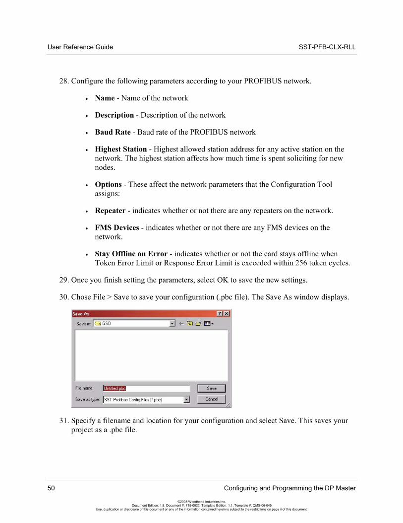
30. Chose File > Save to save your configuration (.pbc file). The Save As window displays.
31. Specify a filename and location for your configuration and select Save. This saves your project as a .pbc file.
50 Configuring and Programming the DP Master
©2008 Woodhead Industries Inc. Document Edition: 1.8, Document #: 715-0022, Template Edition: 1.1, Template #: QMS-06-045
Use, duplication or disclosure of this document or any of the information contained herein is subject to the restrictions on page ii of this document.
SST-PFB-CLX-RLL User Reference Guide
Configuring and Programming the DP Master 51
©2008 Woodhead Industries Inc. Document Edition: 1.8, Document #: 715-0022, Template Edition: 1.1, Template #: QMS-06-045
Use, duplication or disclosure of this document or any of the information contained herein is subject to the restrictions on page ii of this document.
32. To download your configuration, refer to Section 5.3, Downloading to the Scanner.
33. You now have the option of exporting your configuration to a binary (.bss) file using one of the following methods:
• Select Edit/Export Binary... to export your configuration to a (.bss) file
OR
• Right-click on the SST-PFB-CLX-RLL Master and select the Export Binary... option from the shortcut menu.
5.2.2 Online Browsing with DP View in the SST PROFIBUS Tool
1. Verify that the CLX PLC is in Program mode or the PBIM block with the Clear mode enabled is inactive in the PlantScape Control Builder.
2. If you’re using a serial connection, connect your null modem cable between the scanner’s serial port and your PC COM port and verify that you are connected to the PROFIBUS network. If you’re using an RSLinx connection, refer to Section 12.3, Configuring the RSLinx Connection for details.
User Reference Guide SST-PFB-CLX-RLL
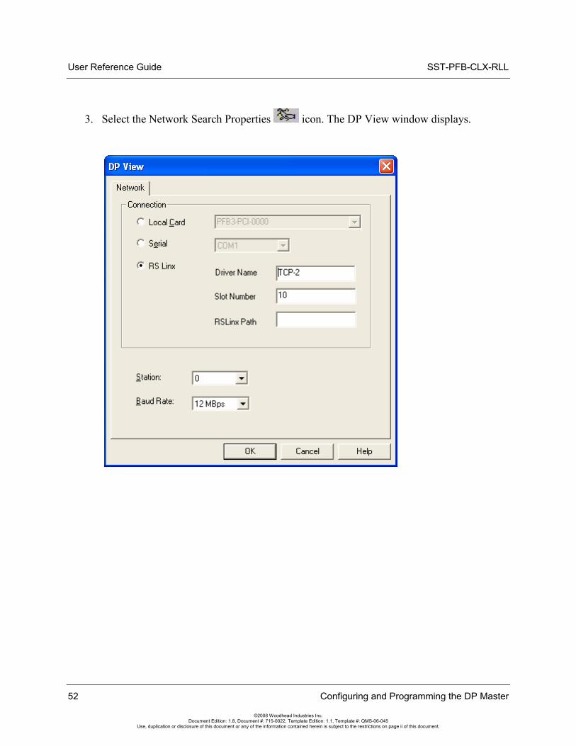
3. Select the Network Search Properties icon. The DP View window displays.
52 Configuring and Programming the DP Master
©2008 Woodhead Industries Inc. Document Edition: 1.8, Document #: 715-0022, Template Edition: 1.1, Template #: QMS-06-045
Use, duplication or disclosure of this document or any of the information contained herein is subject to the restrictions on page ii of this document.
SST-PFB-CLX-RLL User Reference Guide
4. Configure the network by specifying the following:
• Local Card - Default radio button selection only. Select the Serial radio button.
• Serial - Select this radio button for serial communication. This is the COM port to which your serial cable is connected.
• RSLinx – If you have RSLinx Professional installed, specify the Driver Name and the scanner module slot in the rack. For more details, refer to Section 12.3, Configuring the RSLinx Connection.
• Driver Name – Name of the RSLinx Driver set up to communicate over Ethernet with the scanner module
• Slot Number – location of the scanner module in the rack
• RSLinx Path – If the scanner is in a remote rack, this is the relevant path. For more details, refer to Section 12.3, Configuring the RSLinx Connection.
• Station - Set a unique station number, one not used by any of the slaves on the network
• Baud Rate - Slaves that do not support the selected baud rate will not be detected
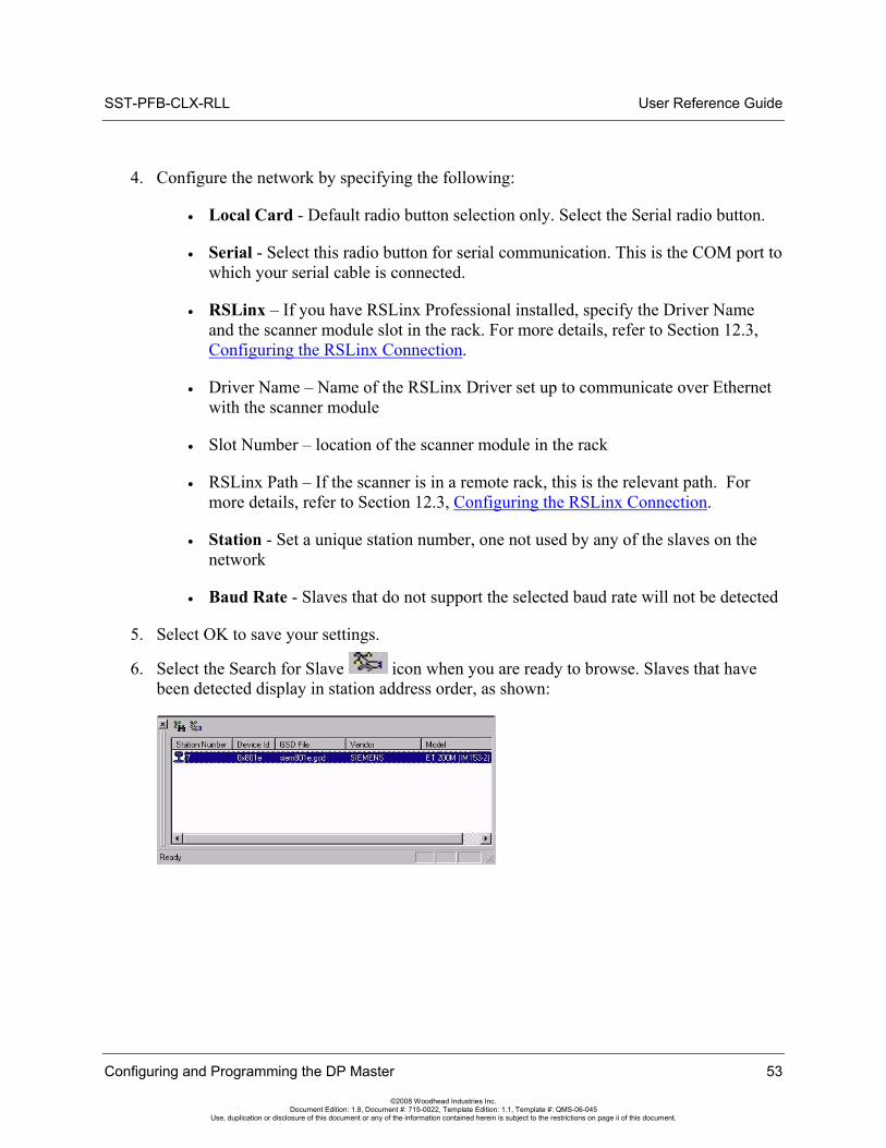
5. Select OK to save your settings.
6. Select the Search for Slave icon when you are ready to browse. Slaves that have been detected display in station address order, as shown:
Configuring and Programming the DP Master 53
©2008 Woodhead Industries Inc. Document Edition: 1.8, Document #: 715-0022, Template Edition: 1.1, Template #: QMS-06-045
Use, duplication or disclosure of this document or any of the information contained herein is subject to the restrictions on page ii of this document.
User Reference Guide SST-PFB-CLX-RLL
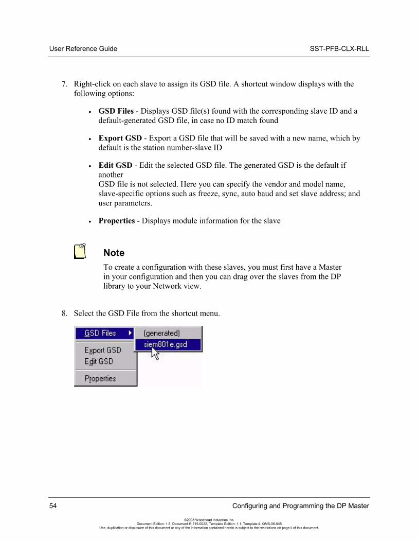
7. Right-click on each slave to assign its GSD file. A shortcut window displays with the following options:
• GSD Files - Displays GSD file(s) found with the corresponding slave ID and a default-generated GSD file, in case no ID match found
• Export GSD - Export a GSD file that will be saved with a new name, which by default is the station number-slave ID
• Edit GSD - Edit the selected GSD file. The generated GSD is the default if another GSD file is not selected. Here you can specify the vendor and model name, slave-specific options such as freeze, sync, auto baud and set slave address; and user parameters.
• Properties - Displays module information for the slave
Note To create a configuration with these slaves, you must first have a Master in your configuration and then you can drag over the slaves from the DP library to your Network view.
8. Select the GSD File from the shortcut menu.
54 Configuring and Programming the DP Master
©2008 Woodhead Industries Inc. Document Edition: 1.8, Document #: 715-0022, Template Edition: 1.1, Template #: QMS-06-045
Use, duplication or disclosure of this document or any of the information contained herein is subject to the restrictions on page ii of this document.
SST-PFB-CLX-RLL User Reference Guide
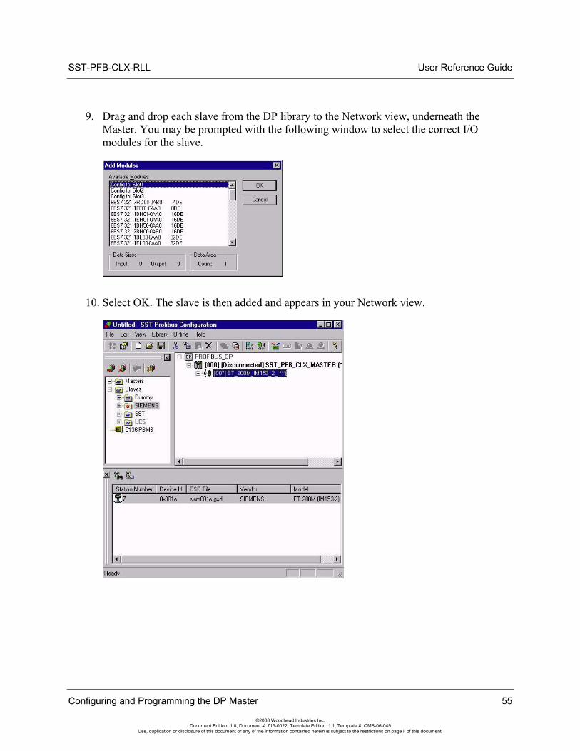
9. Drag and drop each slave from the DP library to the Network view, underneath the Master. You may be prompted with the following window to select the correct I/O modules for the slave.
10. Select OK. The slave is then added and appears in your Network view.
Configuring and Programming the DP Master 55
©2008 Woodhead Industries Inc. Document Edition: 1.8, Document #: 715-0022, Template Edition: 1.1, Template #: QMS-06-045
Use, duplication or disclosure of this document or any of the information contained herein is subject to the restrictions on page ii of this document.
User Reference Guide SST-PFB-CLX-RLL
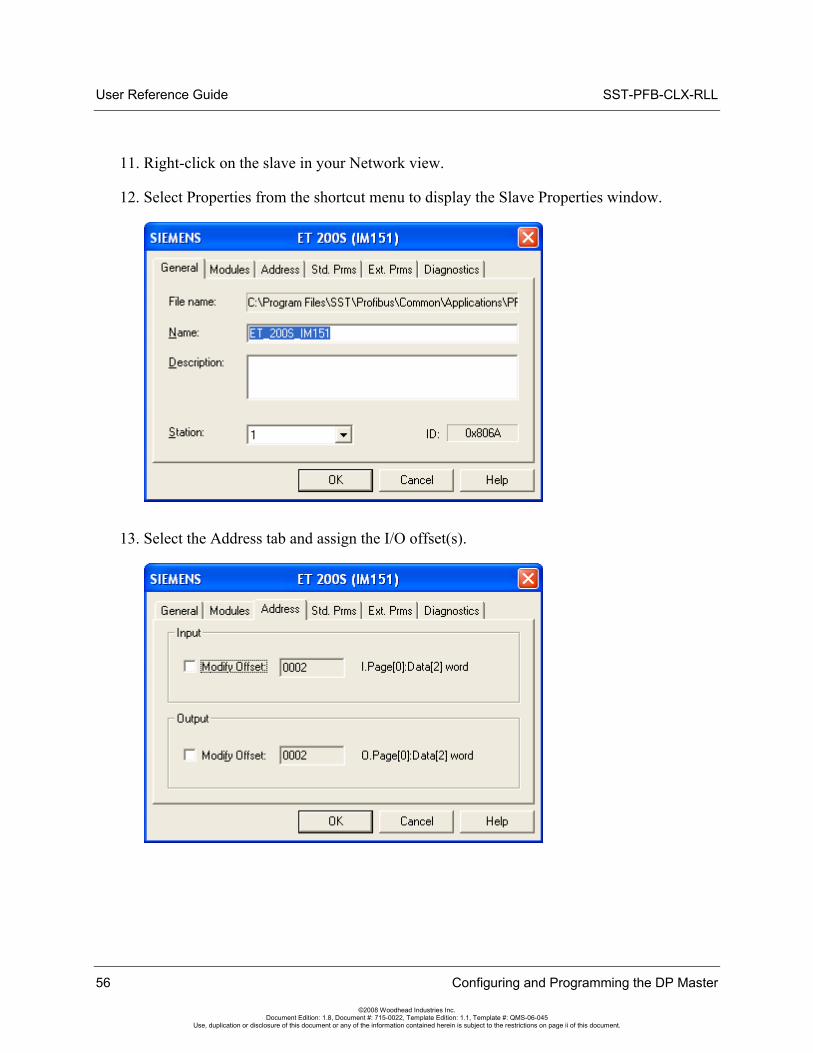
11. Right-click on the slave in your Network view.
12. Select Properties from the shortcut menu to display the Slave Properties window.
13. Select the Address tab and assign the I/O offset(s).
56 Configuring and Programming the DP Master
©2008 Woodhead Industries Inc. Document Edition: 1.8, Document #: 715-0022, Template Edition: 1.1, Template #: QMS-06-045
Use, duplication or disclosure of this document or any of the information contained herein is subject to the restrictions on page ii of this document.
SST-PFB-CLX-RLL User Reference Guide
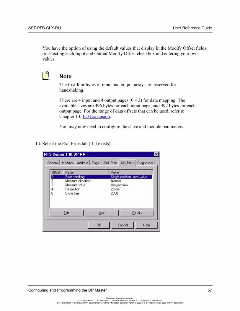
You have the option of using the default values that display in the Modify Offset fields, or selecting each Input and Output Modify Offset checkbox and entering your own values.
Note The first four bytes of input and output arrays are reserved for handshaking.
There are 4 input and 4 output pages (0 – 3) for data mapping. The available sizes are 496 bytes for each input page, and 492 bytes for each output page. For the range of data offsets that can be used, refer to Chapter 13, I/O Expansion.
You may now need to configure the slave and module parameters.
14. Select the Ext. Prms tab (if it exists).
Configuring and Programming the DP Master 57
©2008 Woodhead Industries Inc. Document Edition: 1.8, Document #: 715-0022, Template Edition: 1.1, Template #: QMS-06-045
Use, duplication or disclosure of this document or any of the information contained herein is subject to the restrictions on page ii of this document.
User Reference Guide SST-PFB-CLX-RLL
58 Configuring and Programming the DP Master
©2008 Woodhead Industries Inc. Document Edition: 1.8, Document #: 715-0022, Template Edition: 1.1, Template #: QMS-06-045
Use, duplication or disclosure of this document or any of the information contained herein is subject to the restrictions on page ii of this document.
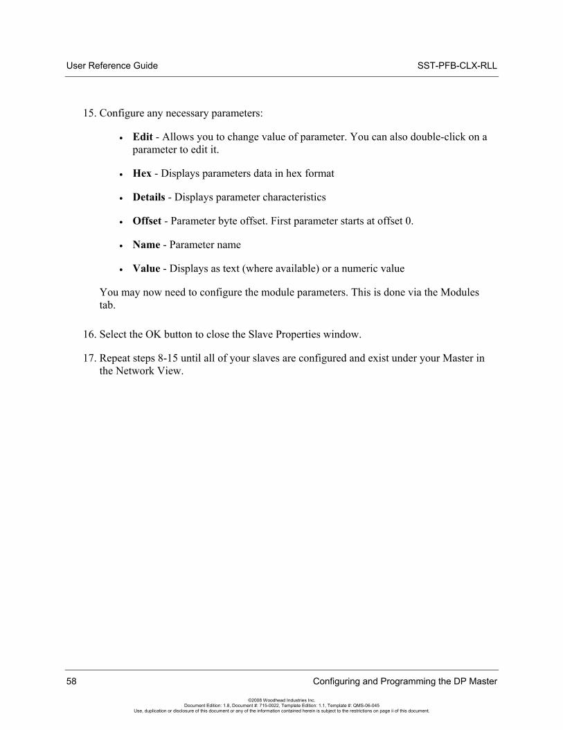
15. Configure any necessary parameters:
• Edit - Allows you to change value of parameter. You can also double-click on a parameter to edit it.
• Hex - Displays parameters data in hex format
• Details - Displays parameter characteristics
• Offset - Parameter byte offset. First parameter starts at offset 0.
• Name - Parameter name
• Value - Displays as text (where available) or a numeric value
You may now need to configure the module parameters. This is done via the Modules tab.
16. Select the OK button to close the Slave Properties window.
17. Repeat steps 8-15 until all of your slaves are configured and exist under your Master in the Network View.

SST-PFB-CLX-RLL User Reference Guide
18. Right-click on PROFIBUS-DP in the Network view to configure the Network Parameters (baud rate and so on), and select Properties from the shortcut menu. The Network window displays.
19. Configure the following parameters according to your PROFIBUS network:
• Name - Name of the network
• Description - Description of the network
• Baud Rate - Baud rate of the PROFIBUS network
• Highest Station - Highest allowed station address for any active station on the network. The highest station affects how much time is spent soliciting for new nodes.
• Options - These affect the network parameters that the Configuration Tool assigns
• Repeater - Indicates whether or not there are any repeaters on the network
• FMS Devices - Indicates whether or not there are any FMS devices on the network.
• Stay Offline on Error - Indicates whether or not the card stays offline when the Token Error Limit or Response Error Limit is exceeded within 256 token cycles.
Configuring and Programming the DP Master 59
©2008 Woodhead Industries Inc. Document Edition: 1.8, Document #: 715-0022, Template Edition: 1.1, Template #: QMS-06-045
Use, duplication or disclosure of this document or any of the information contained herein is subject to the restrictions on page ii of this document.
User Reference Guide SST-PFB-CLX-RLL
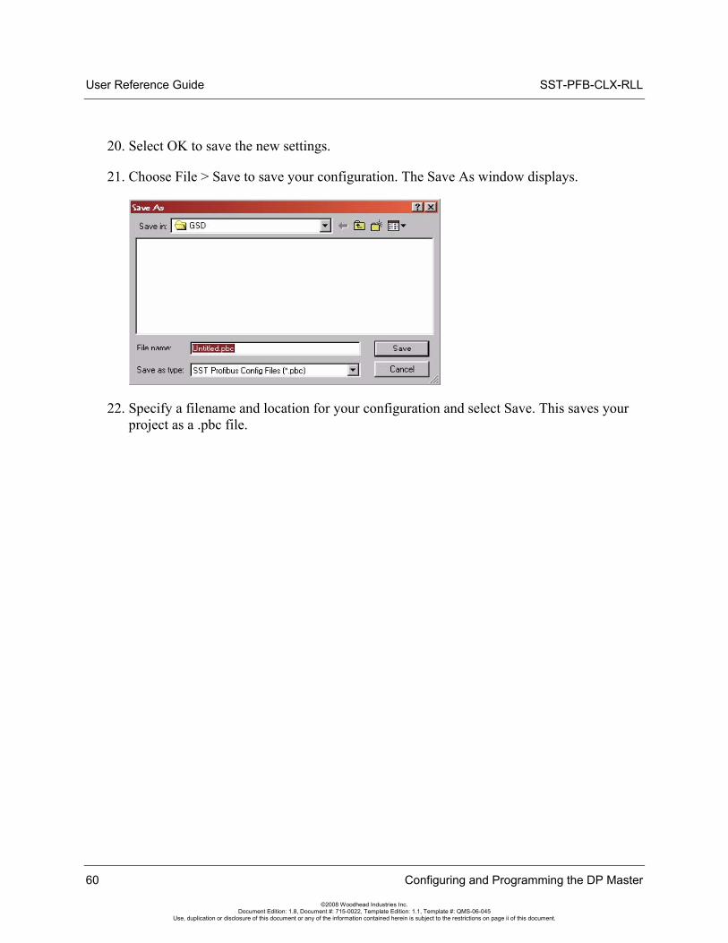
20. Select OK to save the new settings.
21. Choose File > Save to save your configuration. The Save As window displays.
22. Specify a filename and location for your configuration and select Save. This saves your project as a .pbc file.
60 Configuring and Programming the DP Master
©2008 Woodhead Industries Inc. Document Edition: 1.8, Document #: 715-0022, Template Edition: 1.1, Template #: QMS-06-045
Use, duplication or disclosure of this document or any of the information contained herein is subject to the restrictions on page ii of this document.
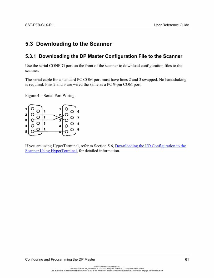
SST-PFB-CLX-RLL User Reference Guide
5.3 Downloading to the Scanner
5.3.1 Downloading the DP Master Configuration File to the Scanner
Use the serial CONFIG port on the front of the scanner to download configuration files to the scanner.
The serial cable for a standard PC COM port must have lines 2 and 3 swapped. No handshaking is required. Pins 2 and 3 are wired the same as a PC 9-pin COM port.
Figure 4: Serial Port Wiring
If you are using HyperTerminal, refer to Section 5.6, Downloading the I/O Configuration to the Scanner Using HyperTerminal, for detailed information.
Configuring and Programming the DP Master 61
©2008 Woodhead Industries Inc. Document Edition: 1.8, Document #: 715-0022, Template Edition: 1.1, Template #: QMS-06-045
Use, duplication or disclosure of this document or any of the information contained herein is subject to the restrictions on page ii of this document.
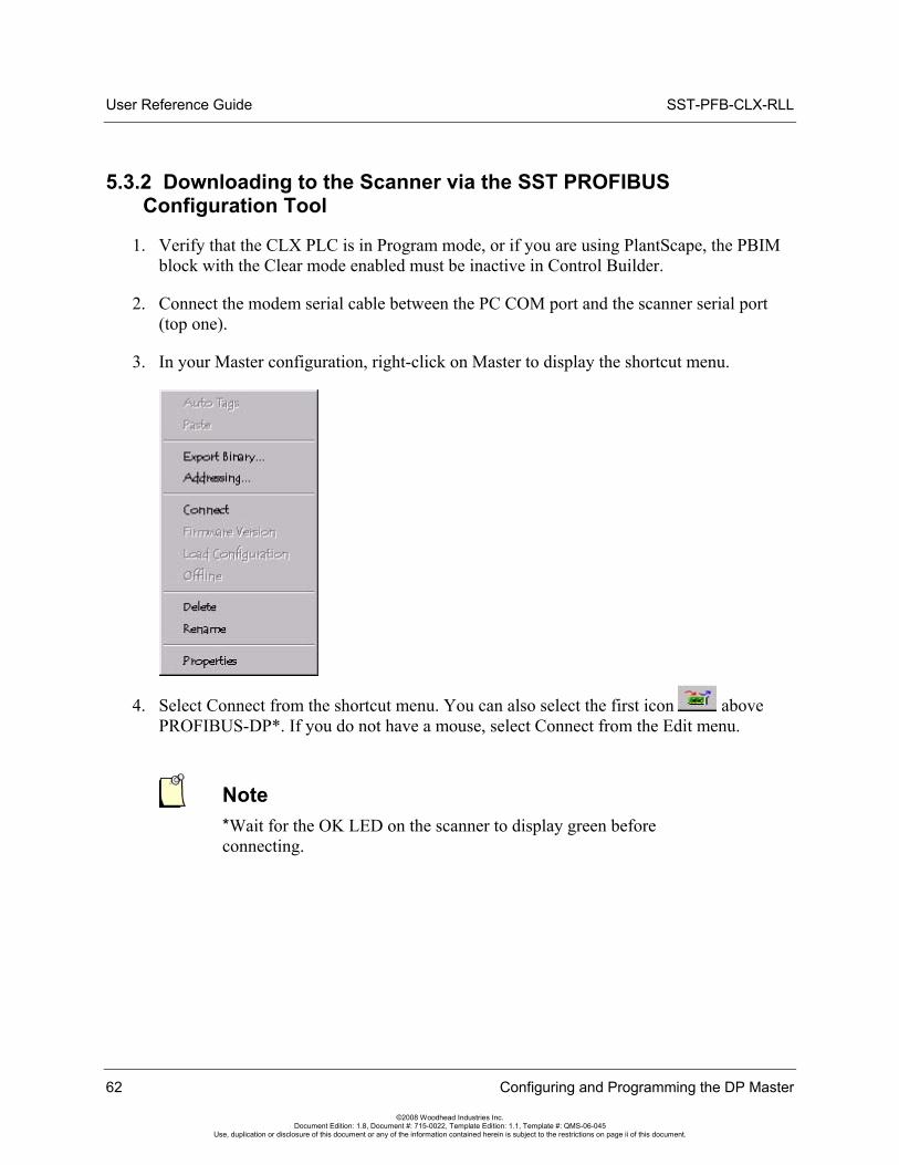
User Reference Guide SST-PFB-CLX-RLL
5.3.2 Downloading to the Scanner via the SST PROFIBUS Configuration Tool
1. Verify that the CLX PLC is in Program mode, or if you are using PlantScape, the PBIM block with the Clear mode enabled must be inactive in Control Builder.
2. Connect the modem serial cable between the PC COM port and the scanner serial port (top one).
3. In your Master configuration, right-click on Master to display the shortcut menu.
4. Select Connect from the shortcut menu. You can also select the first icon above PROFIBUS-DP*. If you do not have a mouse, select Connect from the Edit menu.
Note *Wait for the OK LED on the scanner to display green before connecting.
62 Configuring and Programming the DP Master
©2008 Woodhead Industries Inc. Document Edition: 1.8, Document #: 715-0022, Template Edition: 1.1, Template #: QMS-06-045
Use, duplication or disclosure of this document or any of the information contained herein is subject to the restrictions on page ii of this document.
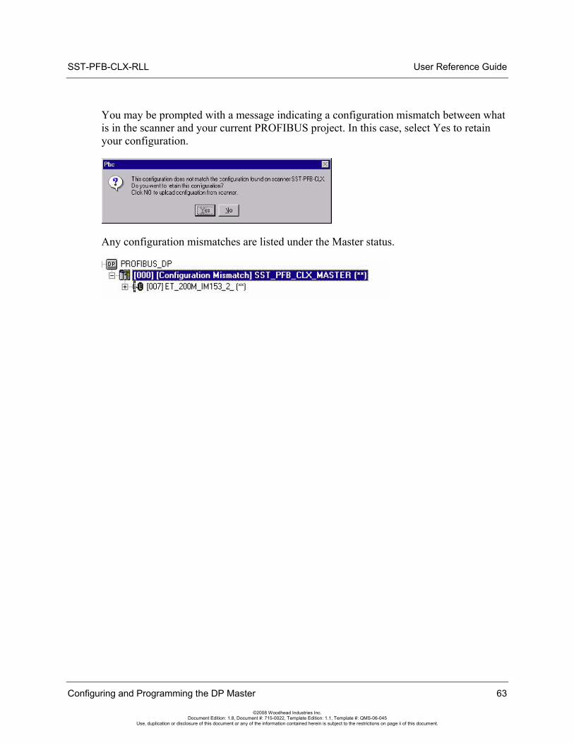
SST-PFB-CLX-RLL User Reference Guide
You may be prompted with a message indicating a configuration mismatch between what is in the scanner and your current PROFIBUS project. In this case, select Yes to retain your configuration.
Any configuration mismatches are listed under the Master status.
Configuring and Programming the DP Master 63
©2008 Woodhead Industries Inc. Document Edition: 1.8, Document #: 715-0022, Template Edition: 1.1, Template #: QMS-06-045
Use, duplication or disclosure of this document or any of the information contained herein is subject to the restrictions on page ii of this document.
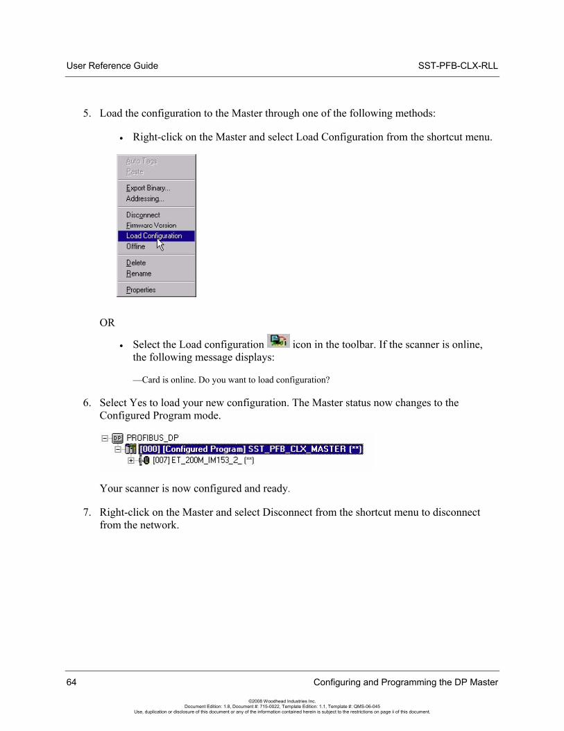
User Reference Guide SST-PFB-CLX-RLL
5. Load the configuration to the Master through one of the following methods:
• Right-click on the Master and select Load Configuration from the shortcut menu.
OR
• Select the Load configuration icon in the toolbar. If the scanner is online, the following message displays:
—Card is online. Do you want to load configuration?
6. Select Yes to load your new configuration. The Master status now changes to the Configured Program mode.
Your scanner is now configured and ready.
7. Right-click on the Master and select Disconnect from the shortcut menu to disconnect from the network.
64 Configuring and Programming the DP Master
©2008 Woodhead Industries Inc. Document Edition: 1.8, Document #: 715-0022, Template Edition: 1.1, Template #: QMS-06-045
Use, duplication or disclosure of this document or any of the information contained herein is subject to the restrictions on page ii of this document.
SST-PFB-CLX-RLL User Reference Guide
5.3.3 Monitoring the Scanner via the SST PROFIBUS Configuration Tool
1. Verify that the scanner is online by switching the CLX PLC to Run mode, or if you’re using PlantScape, ensure that the PBIM block with Clear mode enabled is active in Control Builder. Both the COMM (green) and SYS (red) LEDs should be ON.
2. Switch the CLX PLC back to Program mode. For PlantScape, ensure that the PBIM block is inactive with the Clear mode enabled.
3. To connect to the Master in your PROFIBUS configuration, right-click on the Master.
4. Select Connect from the shortcut menu.
Note You may get a message indicating a configuration mismatch. Select YES to retain and download the configuration.
Configuring and Programming the DP Master 65
©2008 Woodhead Industries Inc. Document Edition: 1.8, Document #: 715-0022, Template Edition: 1.1, Template #: QMS-06-045
Use, duplication or disclosure of this document or any of the information contained herein is subject to the restrictions on page ii of this document.
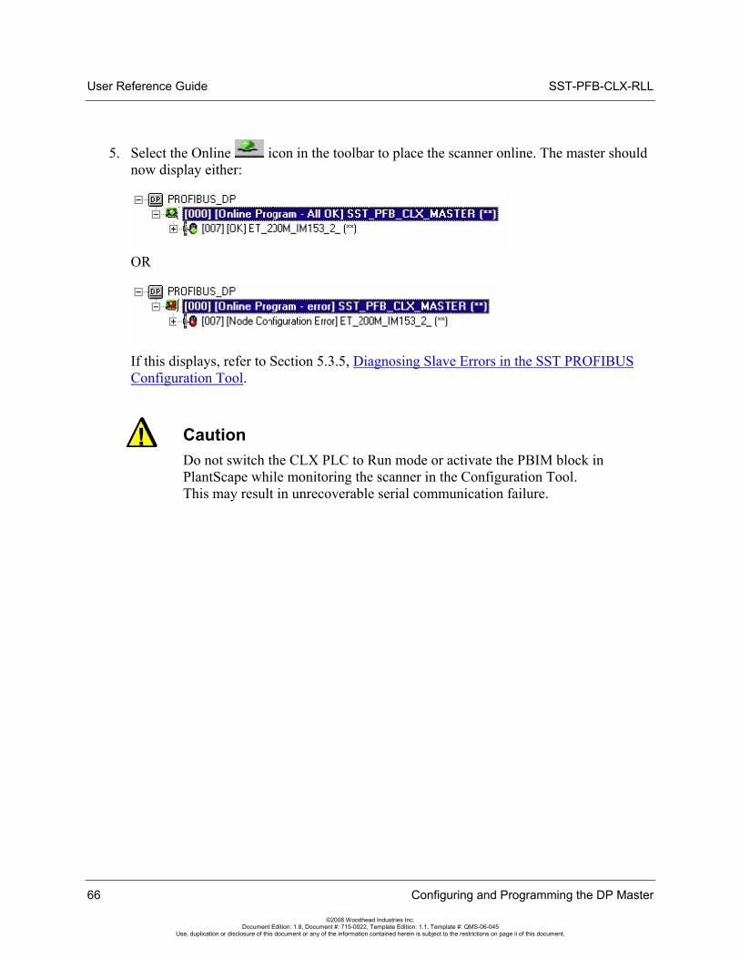
User Reference Guide SST-PFB-CLX-RLL
5. Select the Online icon in the toolbar to place the scanner online. The master should now display either:
OR
If this displays, refer to Section 5.3.5, Diagnosing Slave Errors in the SST PROFIBUS Configuration Tool.
Caution Do not switch the CLX PLC to Run mode or activate the PBIM block in PlantScape while monitoring the scanner in the Configuration Tool. This may result in unrecoverable serial communication failure.
66 Configuring and Programming the DP Master
©2008 Woodhead Industries Inc. Document Edition: 1.8, Document #: 715-0022, Template Edition: 1.1, Template #: QMS-06-045
Use, duplication or disclosure of this document or any of the information contained herein is subject to the restrictions on page ii of this document.
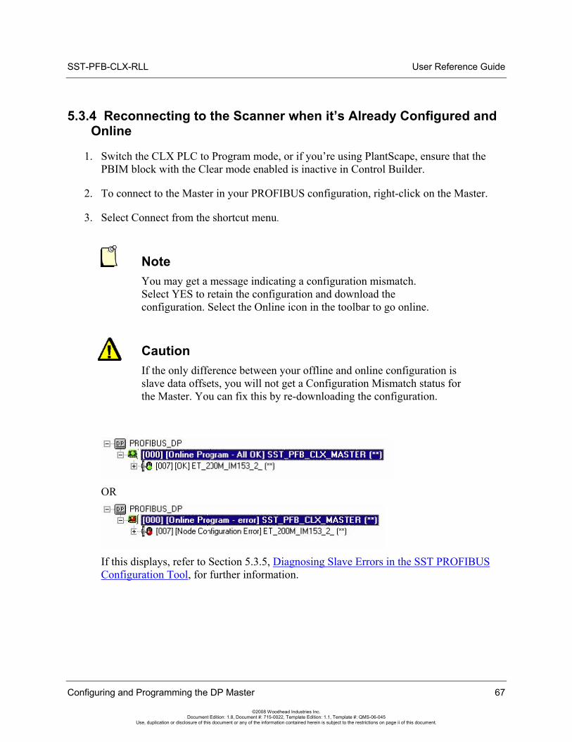
SST-PFB-CLX-RLL User Reference Guide
5.3.4 Reconnecting to the Scanner when it’s Already Configured and Online
1. Switch the CLX PLC to Program mode, or if you’re using PlantScape, ensure that the PBIM block with the Clear mode enabled is inactive in Control Builder.
2. To connect to the Master in your PROFIBUS configuration, right-click on the Master.
3. Select Connect from the shortcut menu.
Note You may get a message indicating a configuration mismatch. Select YES to retain the configuration and download the configuration. Select the Online icon in the toolbar to go online.
Caution If the only difference between your offline and online configuration is slave data offsets, you will not get a Configuration Mismatch status for the Master. You can fix this by re-downloading the configuration.
OR
If this displays, refer to Section 5.3.5, Diagnosing Slave Errors in the SST PROFIBUS Configuration Tool, for further information.
Configuring and Programming the DP Master 67
©2008 Woodhead Industries Inc. Document Edition: 1.8, Document #: 715-0022, Template Edition: 1.1, Template #: QMS-06-045
Use, duplication or disclosure of this document or any of the information contained herein is subject to the restrictions on page ii of this document.
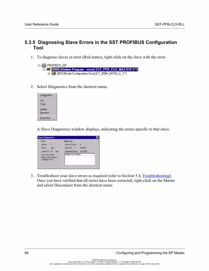
User Reference Guide SST-PFB-CLX-RLL
5.3.5 Diagnosing Slave Errors in the SST PROFIBUS Configuration Tool
1. To diagnose slaves in error (Red status), right-click on the slave with the error.
2. Select Diagnostics from the shortcut menu.
A Slave Diagnostics window displays, indicating the errors specific to that slave.
3. Troubleshoot your slave errors as required (refer to Section 5.4, Troubleshooting). Once you have verified that all errors have been corrected, right-click on the Master and select Disconnect from the shortcut menu.
68 Configuring and Programming the DP Master
©2008 Woodhead Industries Inc. Document Edition: 1.8, Document #: 715-0022, Template Edition: 1.1, Template #: QMS-06-045
Use, duplication or disclosure of this document or any of the information contained herein is subject to the restrictions on page ii of this document.
SST-PFB-CLX-RLL User Reference Guide
Configuring and Programming the DP Master 69
©2008 Woodhead Industries Inc. Document Edition: 1.8, Document #: 715-0022, Template Edition: 1.1, Template #: QMS-06-045
Use, duplication or disclosure of this document or any of the information contained herein is subject to the restrictions on page ii of this document.
5.4 Troubleshooting
Station Non Existent
Check the slave’s PROFIBUS interface to ensure that it is powered on and connected to your network. Ensure that the slave supports the configured baud rate. Also, verify that you are using the Correct GSD file for the slave device by checking the slave’s part number.
Configuration Data Fault
Check that the I/O modules are configured in the order they appear in the slave device and that the I/O modules match the exact description of the modules you selected (i.e., module serial number).
Station Not Ready
If there are still outstanding errors, this is always present. Also, you may be trying to scan the slave too quickly. This may be caused by using a wrong GSD file.
Extended Diagnostic Data
This is device specific. Retrieve the data by requesting the slave diagnostics in your RSLogix 5000 sample program. Extended diagnostic data starts at byte 7 of the slave diagnostics. Compare the values with the descriptions that may be available for the slave by viewing the slave’s properties and selecting the Diagnostics tab in the Configuration Tool.
Function Not Supported
The slave does not support commands like SYNC or FREEZE coming from the Master. Check that you are using the correct GSD file.
Invalid Slave Response
This usually occurs when the slave is returning more diagnostic information than the Master can handle. Check your GSD file.
User Reference Guide SST-PFB-CLX-RLL
70 Configuring and Programming the DP Master
©2008 Woodhead Industries Inc. Document Edition: 1.8, Document #: 715-0022, Template Edition: 1.1, Template #: QMS-06-045
Use, duplication or disclosure of this document or any of the information contained herein is subject to the restrictions on page ii of this document.
Parameter Fault
This usually means an incorrect Indent - Number or Invalid parameter sent to the slave. Check that you have set the slave and module parameters correctly by selecting the Ext. Prms. tab under the slave/module’s properties.
Master Lock
The DP slave has been parameterized by another Master. Take the controlling Master offline.
Param/Config Required
This remains present until the parameterization has completed properly. You may be using the incorrect GSD file or you haven't set the slave and module parameters to the correct values. Check the slave and module parameters by selecting the Ext. Prms. tab under the slave/module’s properties.
Static Diagnostics
Check your slave diagnostic data in the scanner status area using the RSLogix 5000 sample Ladder Logic, which already includes the logic to retrieve this. Write xx05 (xx = station number) to the CMD Argument register (Local:Slot:O.Data [1]). The slave diagnostics display, starting at Local:Slot:S.Data [59].
DP Slave Set
This is OK and is set by the slave.
WatchDog
This is OK and should be set when the slave status is OK.
Ext Diags Overflow
More Diagnostic data is being returned from the slave than what is specified in its GSD file. You may be using an incorrect GSD file.
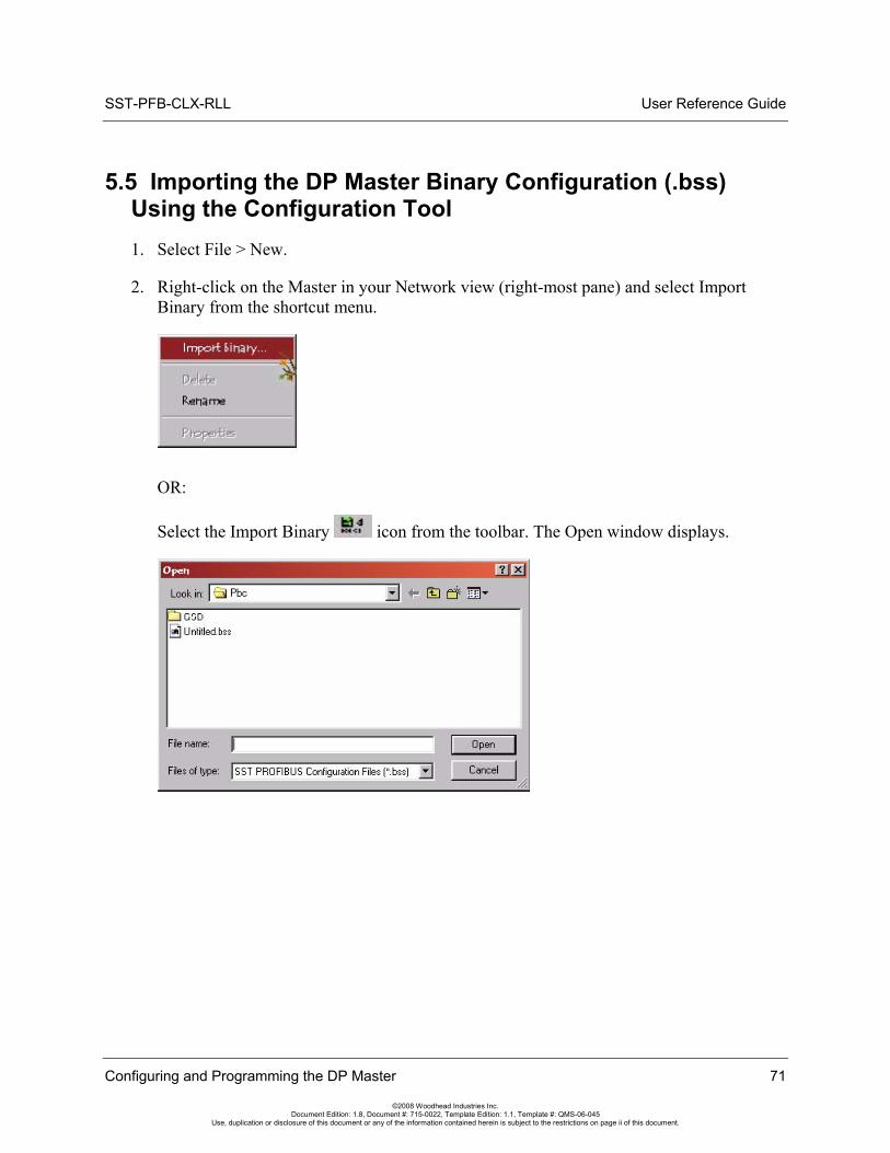
SST-PFB-CLX-RLL User Reference Guide
5.5 Importing the DP Master Binary Configuration (.bss) Using the Configuration Tool 1. Select File > New.
2. Right-click on the Master in your Network view (right-most pane) and select Import Binary from the shortcut menu.
OR:
Select the Import Binary icon from the toolbar. The Open window displays.
Configuring and Programming the DP Master 71
©2008 Woodhead Industries Inc. Document Edition: 1.8, Document #: 715-0022, Template Edition: 1.1, Template #: QMS-06-045
Use, duplication or disclosure of this document or any of the information contained herein is subject to the restrictions on page ii of this document.
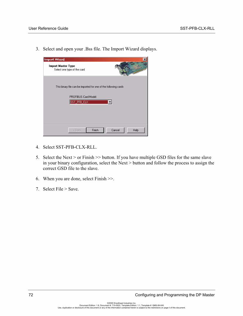
User Reference Guide SST-PFB-CLX-RLL
3. Select and open your .Bss file. The Import Wizard displays.
4. Select SST-PFB-CLX-RLL.
5. Select the Next > or Finish >> button. If you have multiple GSD files for the same slave in your binary configuration, select the Next > button and follow the process to assign the correct GSD file to the slave.
6. When you are done, select Finish >>.
7. Select File > Save.
72 Configuring and Programming the DP Master
©2008 Woodhead Industries Inc. Document Edition: 1.8, Document #: 715-0022, Template Edition: 1.1, Template #: QMS-06-045
Use, duplication or disclosure of this document or any of the information contained herein is subject to the restrictions on page ii of this document.
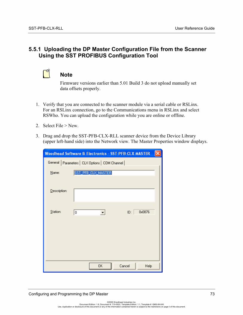
SST-PFB-CLX-RLL User Reference Guide
5.5.1 Uploading the DP Master Configuration File from the Scanner Using the SST PROFIBUS Configuration Tool
Note Firmware versions earlier than 5.01 Build 3 do not upload manually set data offsets properly.
1. Verify that you are connected to the scanner module via a serial cable or RSLinx. For an RSLinx connection, go to the Communications menu in RSLinx and select RSWho. You can upload the configuration while you are online or offline.
2. Select File > New.
3. Drag and drop the SST-PFB-CLX-RLL scanner device from the Device Library (upper left-hand side) into the Network view. The Master Properties window displays.
Configuring and Programming the DP Master 73
©2008 Woodhead Industries Inc. Document Edition: 1.8, Document #: 715-0022, Template Edition: 1.1, Template #: QMS-06-045
Use, duplication or disclosure of this document or any of the information contained herein is subject to the restrictions on page ii of this document.
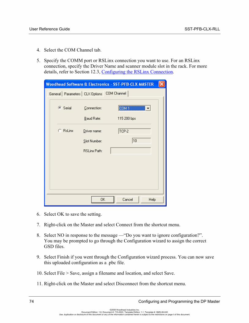
User Reference Guide SST-PFB-CLX-RLL
4. Select the COM Channel tab.
5. Specify the COMM port or RSLinx connection you want to use. For an RSLinx connection, specify the Driver Name and scanner module slot in the rack. For more details, refer to Section 12.3, Configuring the RSLinx Connection.
6. Select OK to save the setting.
7. Right-click on the Master and select Connect from the shortcut menu.
8. Select NO in response to the message —“Do you want to ignore configuration?”. You may be prompted to go through the Configuration wizard to assign the correct GSD files.
9. Select Finish if you went through the Configuration wizard process. You can now save this uploaded configuration as a .pbc file.
10. Select File > Save, assign a filename and location, and select Save.
11. Right-click on the Master and select Disconnect from the shortcut menu.
74 Configuring and Programming the DP Master
©2008 Woodhead Industries Inc. Document Edition: 1.8, Document #: 715-0022, Template Edition: 1.1, Template #: QMS-06-045
Use, duplication or disclosure of this document or any of the information contained herein is subject to the restrictions on page ii of this document.
SST-PFB-CLX-RLL User Reference Guide
5.6 Downloading the I/O Configuration to the Scanner Using HyperTerminal
If you are using HyperTerminal, here is how to set up a connection:
1. Start HyperTerminal and create a new connection.
2. For Connect using:, select Direct to Comn, where "n" is the serial port you are using.
3. Select 115200 Bits per second, 8 Data bits, set Parity to None, select 1 Stop Bit, and set Flow control to None. You should now be able to communicate with the scanner serial port.
4. Connect to the serial port using your communication software. The scanner serial port supports any baud rate from 9600 baud to 115 Kbaud, with no parity, 8 data bits, 1 stop bit and flow control set to None. The scanner automatically detects the baud rate you are using.
Note When configuring the scanner, the CLX PLC must be in Program mode, or if you’re using PlantScape, the PBIM block with the Clear mode enabled must be inactive in Control Builder.
Configuring and Programming the DP Master 75
©2008 Woodhead Industries Inc. Document Edition: 1.8, Document #: 715-0022, Template Edition: 1.1, Template #: QMS-06-045
Use, duplication or disclosure of this document or any of the information contained herein is subject to the restrictions on page ii of this document.
User Reference Guide SST-PFB-CLX-RLL
5. Type an asterisk (*) to get the scanner's attention. You may need to type several asterisks (*) to let the scanner auto-detect the baud rate being used. The scanner displays the message:
Copyright (c) 1995-2000 SST/Woodhead Canada Ltd.For SST-PFB-CLX-RLL CardVersion x.xxReading Configuration from FLASH...
Note
If the module has no configuration in flash, one of two possible warning messages may be displayed in Hyperterminal:
• With no connection to the CPU, the error will be:
Reading Configuration from FLASH... Error '23' while Reading FLASH
• With a connection to CPU, the error will be:
Reading Configuration from FLASH... Error '20' while Reading FLASH
Once a configuration is saved in flash, these errors will no longer occur.
A greater than symbol (>) prompts you at the terminal.
The scanner is now in Config mode. While in Config mode, the scanner COMM and SYS LEDs flash amber alternately. You cannot put the scanner online until you exit from Config mode.
6. Issue the RecBssXmodem command, then initiate an XModem file download from your communication software. Refer to the documentation supplied with your Communication software for more detailed information.
76 Configuring and Programming the DP Master
©2008 Woodhead Industries Inc. Document Edition: 1.8, Document #: 715-0022, Template Edition: 1.1, Template #: QMS-06-045
Use, duplication or disclosure of this document or any of the information contained herein is subject to the restrictions on page ii of this document.
SST-PFB-CLX-RLL User Reference Guide
7. Type Exit to end the Serial communication if prompted with:
Configuration has changed. Do you want to UPDATE PLASH? (y/ n)
8. Type "y" and press ENTER to accept.
Note When you download a Configuration file to the scanner, the configuration is stored in memory on the scanner. Use the UpdFlash command to store the configuration into flash memory.
5.6.1 Listing Available Commands
Once you are talking to the scanner, type Help at the terminal to view a summary of the available commands. Not all available commands are listed in the main Help. There are several additional Help commands to show the other commands.
The following table lists commonly used serial port commands:
Table 9: Commonly Used Port Commands
Command Description
HelpNet Lists commands to set network parameters.
HelpMas Lists commands related to DP master operation.
ShowNet Displays network parameters.
ShowMas Displays the DP master configuration.
UpdFlash Stores the current network and DP master configuration into flash memory.
Ver Displays the version number of the firmware running on the scanner.
RecBssXmodem Receives a DP master configuration exported as a binary file from the SST PROFIBUS Configuration Tool. Initiates the download of your DP master Binary configuration exported from the SST PROFIBUS Configuration Tool.
Exit Exits terminal mode and places the module in offline configuration state.
Configuring and Programming the DP Master 77
©2008 Woodhead Industries Inc. Document Edition: 1.8, Document #: 715-0022, Template Edition: 1.1, Template #: QMS-06-045
Use, duplication or disclosure of this document or any of the information contained herein is subject to the restrictions on page ii of this document.
User Reference Guide SST-PFB-CLX-RLL
78 Configuring and Programming the DP Master
©2008 Woodhead Industries Inc. Document Edition: 1.8, Document #: 715-0022, Template Edition: 1.1, Template #: QMS-06-045
Use, duplication or disclosure of this document or any of the information contained herein is subject to the restrictions on page ii of this document.
5.6.2 Exiting Config Mode
To exit Config mode and let the scanner complete its start-up, issue the Exit command. You must do this before the scanner can be put online. The scanner turns off both LEDs when it is no longer in Config mode.
If there have been changes to the Configuration, the scanner will ask you whether you want to store those changes in flash before you exit.
5.7 Errors
5.7.1 Network Parameter Errors
The following status errors may occur when setting the Network parameters. Values are in hexadecimal.
Table 10: Network Parameter Errors
Value Error Type
02h STS_BAD_BAUD
03h STS_BAD_STN_ADR
04h STS_BAD_HI_STN_ADR
05h STS_BAD_TOK_ROT
06h STS_BAD_SLOT_TME
07h STS_BAD_IDLE_1
08h STS_BAD_IDLE_2
09h STS_BAD_RDY_TME
0ah STS_BAD_QUI_TME
0bh STS_BAD_GAP_UPD
0ch STS_BAD_TOK_RETRY
0dh STS_BAD_MSG_RETRY
0eh STS_BAD_TOK_ERR_LIM
0fh STS_BAD_RSP_ERR_LIM
10h STS_BAUD_DET_ERROR
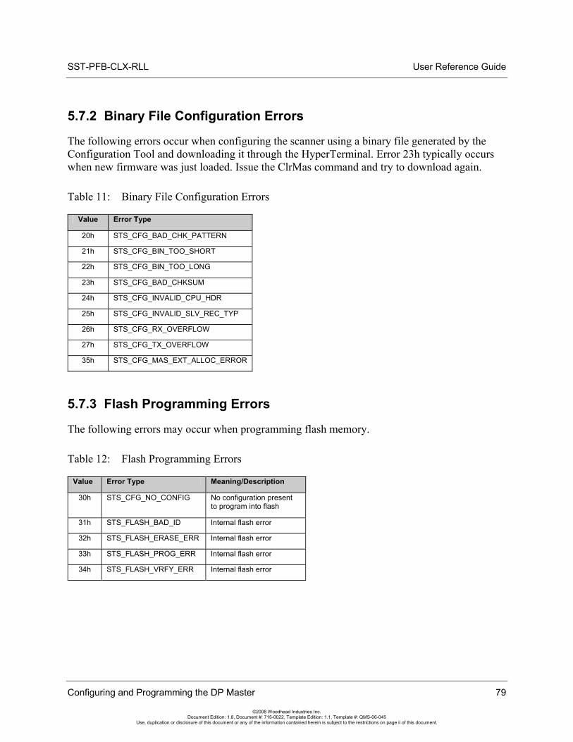
SST-PFB-CLX-RLL User Reference Guide
Configuring and Programming the DP Master 79
©2008 Woodhead Industries Inc. Document Edition: 1.8, Document #: 715-0022, Template Edition: 1.1, Template #: QMS-06-045
Use, duplication or disclosure of this document or any of the information contained herein is subject to the restrictions on page ii of this document.
5.7.2 Binary File Configuration Errors
The following errors occur when configuring the scanner using a binary file generated by the Configuration Tool and downloading it through the HyperTerminal. Error 23h typically occurs when new firmware was just loaded. Issue the ClrMas command and try to download again.
Table 11: Binary File Configuration Errors
Value Error Type
20h STS_CFG_BAD_CHK_PATTERN
21h STS_CFG_BIN_TOO_SHORT
22h STS_CFG_BIN_TOO_LONG
23h STS_CFG_BAD_CHKSUM
24h STS_CFG_INVALID_CPU_HDR
25h STS_CFG_INVALID_SLV_REC_TYP
26h STS_CFG_RX_OVERFLOW
27h STS_CFG_TX_OVERFLOW
35h STS_CFG_MAS_EXT_ALLOC_ERROR
5.7.3 Flash Programming Errors
The following errors may occur when programming flash memory.
Table 12: Flash Programming Errors
Value Error Type Meaning/Description
30h STS_CFG_NO_CONFIG No configuration present to program into flash
31h STS_FLASH_BAD_ID Internal flash error
32h STS_FLASH_ERASE_ERR Internal flash error
33h STS_FLASH_PROG_ERR Internal flash error
34h STS_FLASH_VRFY_ERR Internal flash error
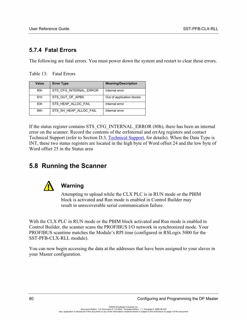
User Reference Guide SST-PFB-CLX-RLL
5.7.4 Fatal Errors
The following are fatal errors. You must power down the system and restart to clear these errors.
Table 13: Fatal Errors
Value Error Type Meaning/Description
80h STS_CFG_INTERNAL_ERROR Internal error
81h STS_OUT_OF_APBS Out of application blocks
83h STS_HEAP_ALLOC_FAIL Internal error
84h STS_SH_HEAP_ALLOC_FAIL Internal error
If the status register contains STS_CFG_INTERNAL_ERROR (80h), there has been an internal error on the scanner. Record the contents of the errInternal and errArg registers and contact Technical Support (refer to Section D.3, Technical Support, for details). When the Data Type is INT, these two status registers are located in the high byte of Word offset 24 and the low byte of Word offset 25 in the Status area
5.8 Running the Scanner
Warning Attempting to upload while the CLX PLC is in RUN mode or the PBIM block is activated and Run mode is enabled in Control Builder may result in unrecoverable serial communication failure.
With the CLX PLC in RUN mode or the PBIM block activated and Run mode is enabled in Control Builder, the scanner scans the PROFIBUS I/O network in synchronized mode. Your PROFIBUS scantime matches the Module’s RPI time (configured in RSLogix 5000 for the SST-PFB-CLX-RLL module).
You can now begin accessing the data at the addresses that have been assigned to your slaves in your Master configuration.
80 Configuring and Programming the DP Master
©2008 Woodhead Industries Inc. Document Edition: 1.8, Document #: 715-0022, Template Edition: 1.1, Template #: QMS-06-045
Use, duplication or disclosure of this document or any of the information contained herein is subject to the restrictions on page ii of this document.
SST-PFB-CLX-RLL User Reference Guide
Configuring and Programming the DP Master 81
©2008 Woodhead Industries Inc. Document Edition: 1.8, Document #: 715-0022, Template Edition: 1.1, Template #: QMS-06-045
Use, duplication or disclosure of this document or any of the information contained herein is subject to the restrictions on page ii of this document.
5.8.1 CLX Modes
The scanner's mode of operation follows the CLX PLC mode of operation (Program, Test, Run).
• When the CLX is in Program mode, the scanner outputs are off and inputs hold their last state. Also, the PROFIBUS scanner is no longer synchronized to the RPI time.
• When the CLX is in Test mode, inputs are read and updated but outputs are off. Also, the PROFIBUS scanner is no longer synchronized to the RPI time.
• When the CLX is in Run mode, the scanner updates inputs and outputs and is synchronized to the RPI time.
5.8.2 PBIM Modes
The scanner's mode of operation follows the operation state of the PBIM block in Control Builder (Active or Inactive).
• When the PBIM Block is active with Clear mode enabled, the scanner outputs are off and inputs continue to get updated. Also, the PROFIBUS scan is no longer synchronized to the RPI time.
• When the PBIM Block is active with Run mode enabled, the scanner updates inputs and outputs and is synchronized to the RPI time.
• When the PBIM block is inactive, the scanner input and output areas in the Control Builder are not updated. As a result, the PROFIBUS scan is no longer synchronized to the RPI time.
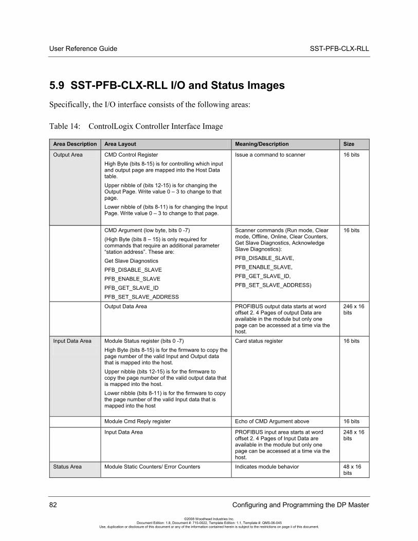
User Reference Guide SST-PFB-CLX-RLL
82 Configuring and Programming the DP Master
©2008 Woodhead Industries Inc. Document Edition: 1.8, Document #: 715-0022, Template Edition: 1.1, Template #: QMS-06-045
Use, duplication or disclosure of this document or any of the information contained herein is subject to the restrictions on page ii of this document.
5.9 SST-PFB-CLX-RLL I/O and Status Images Specifically, the I/O interface consists of the following areas:
Table 14: ControlLogix Controller Interface Image
Area Description Area Layout Meaning/Description Size
Output Area CMD Control Register High Byte (bits 8-15) is for controlling which input and output page are mapped into the Host Data table. Upper nibble of (bits 12-15) is for changing the Output Page. Write value 0 – 3 to change to that page. Lower nibble of (bits 8-11) is for changing the Input Page. Write value 0 – 3 to change to that page.
Issue a command to scanner 16 bits
CMD Argument (low byte, bits 0 -7) (High Byte (bits 8 – 15) is only required for commands that require an additional parameter “station address”. These are: Get Slave Diagnostics PFB_DISABLE_SLAVE PFB_ENABLE_SLAVE PFB_GET_SLAVE_ID PFB_SET_SLAVE_ADDRESS
Scanner commands (Run mode, Clear mode, Offline, Online, Clear Counters, Get Slave Diagnostics, Acknowledge Slave Diagnostics): PFB_DISABLE_SLAVE, PFB_ENABLE_SLAVE, PFB_GET_SLAVE_ID, PFB_SET_SLAVE_ADDRESS)
16 bits
Output Data Area PROFIBUS output data starts at word offset 2. 4 Pages of output Data are available in the module but only one page can be accessed at a time via the host.
246 x 16 bits
Input Data Area
Module Status register (bits 0 -7) High Byte (bits 8-15) is for the firmware to copy the page number of the valid Input and Output data that is mapped into the host. Upper nibble (bits 12-15) is for the firmware to copy the page number of the valid output data that is mapped into the host. Lower nibble (bits 8-11) is for the firmware to copy the page number of the valid Input data that is mapped into the host
Card status register 16 bits
Module Cmd Reply register Echo of CMD Argument above 16 bits
Input Data Area
PROFIBUS input area starts at word offset 2. 4 Pages of Input Data are available in the module but only one page can be accessed at a time via the host.
248 x 16 bits
Status Area Module Static Counters/ Error Counters Indicates module behavior 48 x 16 bits
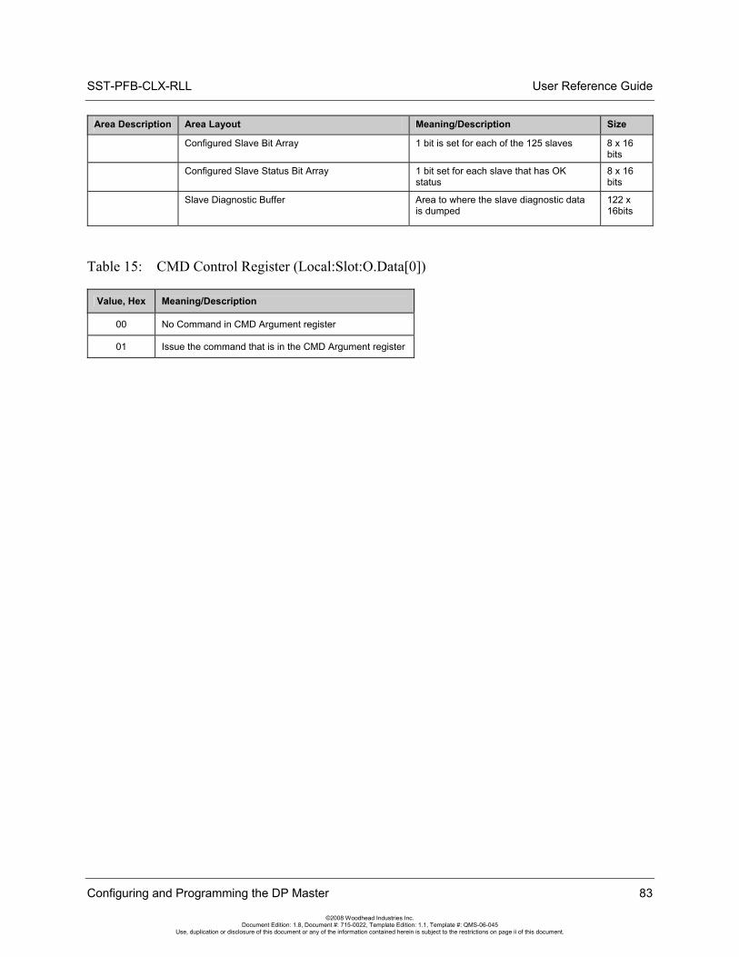
SST-PFB-CLX-RLL User Reference Guide
Configuring and Programming the DP Master 83
©2008 Woodhead Industries Inc. Document Edition: 1.8, Document #: 715-0022, Template Edition: 1.1, Template #: QMS-06-045
Use, duplication or disclosure of this document or any of the information contained herein is subject to the restrictions on page ii of this document.
Area Description Area Layout Meaning/Description Size
Configured Slave Bit Array 1 bit is set for each of the 125 slaves 8 x 16 bits
Configured Slave Status Bit Array 1 bit set for each slave that has OK status
8 x 16 bits
Slave Diagnostic Buffer Area to where the slave diagnostic data is dumped
122 x 16bits
Table 15: CMD Control Register (Local:Slot:O.Data[0])
Value, Hex Meaning/Description
00 No Command in CMD Argument register
01 Issue the command that is in the CMD Argument register
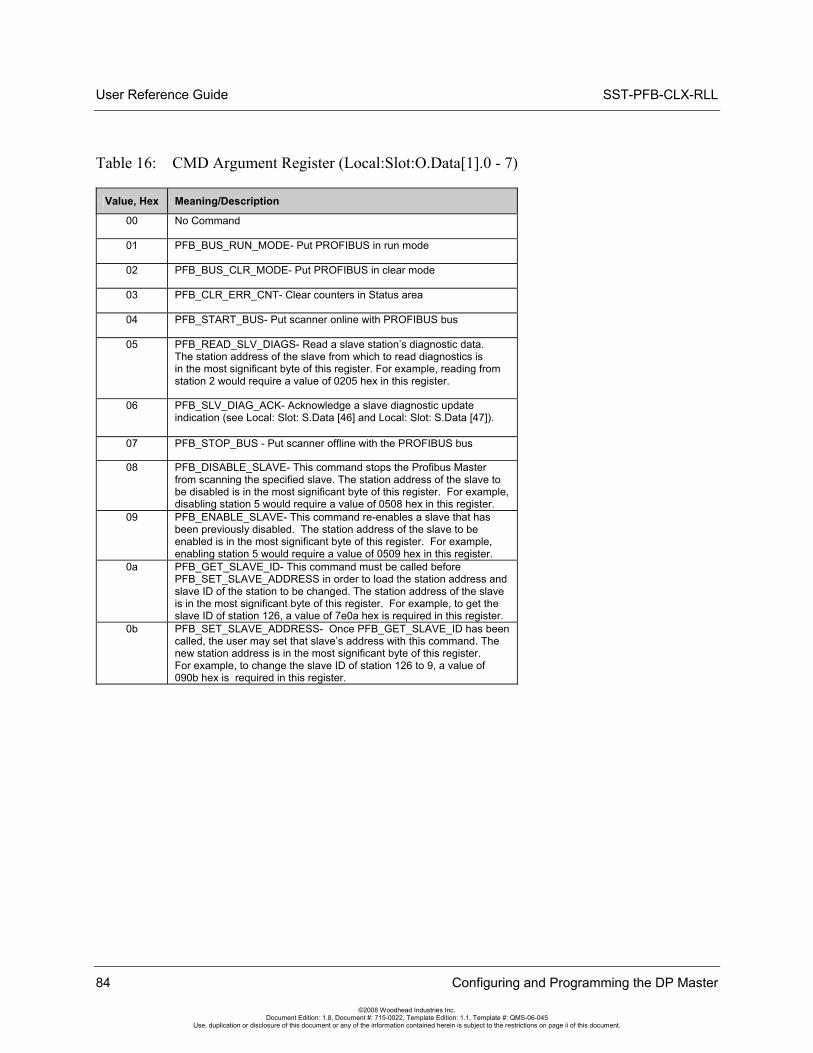
User Reference Guide SST-PFB-CLX-RLL
84 Configuring and Programming the DP Master
©2008 Woodhead Industries Inc. Document Edition: 1.8, Document #: 715-0022, Template Edition: 1.1, Template #: QMS-06-045
Use, duplication or disclosure of this document or any of the information contained herein is subject to the restrictions on page ii of this document.
Table 16: CMD Argument Register (Local:Slot:O.Data[1].0 - 7)
Value, Hex Meaning/Description
00 No Command
01 PFB_BUS_RUN_MODE- Put PROFIBUS in run mode
02 PFB_BUS_CLR_MODE- Put PROFIBUS in clear mode
03 PFB_CLR_ERR_CNT- Clear counters in Status area
04 PFB_START_BUS- Put scanner online with PROFIBUS bus
05 PFB_READ_SLV_DIAGS- Read a slave station’s diagnostic data. The station address of the slave from which to read diagnostics is in the most significant byte of this register. For example, reading from station 2 would require a value of 0205 hex in this register.
06 PFB_SLV_DIAG_ACK- Acknowledge a slave diagnostic update indication (see Local: Slot: S.Data [46] and Local: Slot: S.Data [47]).
07 PFB_STOP_BUS - Put scanner offline with the PROFIBUS bus
08 PFB_DISABLE_SLAVE- This command stops the Profibus Master from scanning the specified slave. The station address of the slave to be disabled is in the most significant byte of this register. For example, disabling station 5 would require a value of 0508 hex in this register.
09 PFB_ENABLE_SLAVE- This command re-enables a slave that has been previously disabled. The station address of the slave to be enabled is in the most significant byte of this register. For example, enabling station 5 would require a value of 0509 hex in this register.
0a PFB_GET_SLAVE_ID- This command must be called before PFB_SET_SLAVE_ADDRESS in order to load the station address and slave ID of the station to be changed. The station address of the slave is in the most significant byte of this register. For example, to get the slave ID of station 126, a value of 7e0a hex is required in this register.
0b PFB_SET_SLAVE_ADDRESS- Once PFB_GET_SLAVE_ID has been called, the user may set that slave’s address with this command. The new station address is in the most significant byte of this register. For example, to change the slave ID of station 126 to 9, a value of 090b hex is required in this register.
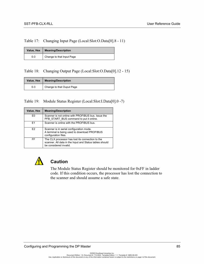
SST-PFB-CLX-RLL User Reference Guide
Table 17: Changing Input Page (Local:Slot:O.Data[0].8 - 11)
Value, Hex Meaning/Description
0-3 Change to that Input Page
Table 18: Changing Output Page (Local:Slot:O.Data[0].12 - 15)
Value, Hex Meaning/Description
0-3 Change to that Ouput Page
Table 19: Module Status Register (Local:Slot:I.Data[0].0 -7)
Value, Hex Meaning/Description
E0 Scanner is not online with PROFIBUS bus. Issue the PFB_START_BUS command to put it online.
E1 Scanner is online with the PROFIBUS bus.
E2 Scanner is in serial configuration mode. A terminal is being used to download PROFIBUS configuration files.
FF The CLX processor has lost its connection to the scanner. All data in the Input and Status tables should be considered invalid.
Caution The Module Status Register should be monitored for 0xFF in ladder code. If this condition occurs, the processor has lost the connection to the scanner and should assume a safe state.
Configuring and Programming the DP Master 85
©2008 Woodhead Industries Inc. Document Edition: 1.8, Document #: 715-0022, Template Edition: 1.1, Template #: QMS-06-045
Use, duplication or disclosure of this document or any of the information contained herein is subject to the restrictions on page ii of this document.
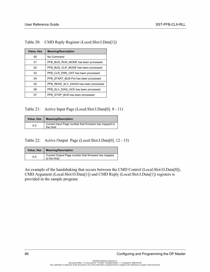
User Reference Guide SST-PFB-CLX-RLL
86 Configuring and Programming the DP Master
©2008 Woodhead Industries Inc. Document Edition: 1.8, Document #: 715-0022, Template Edition: 1.1, Template #: QMS-06-045
Use, duplication or disclosure of this document or any of the information contained herein is subject to the restrictions on page ii of this document.
Table 20: CMD Reply Register (Local:Slot:I.Data[1])
Value, Hex Meaning/Description
00 No Command
01 PFB_BUS_RUN_MODE has been processed
02 PFB_BUS_CLR_MODE has been processed
03 PFB_CLR_ERR_CNT has been processed
04 PFB_START_BUS-Put has been processed
05 PFB_READ_SLV_DIAGS has been processed
06 PFB_SLV_DIAG_ACK has been processed
07 PFB_STOP_BUS has been processed
Table 21: Active Input Page (Local:Slot:I.Data[0]. 8 - 11)
Value, Hex Meaning/Description
0-3 Current Input Page number that firmware has mapped to the Host
Table 22: Active Output Page (Local:Slot:I.Data[0]. 12 - 15)
Value, Hex Meaning/Description
0-3 Current Output Page number that firmware has mapped to the Host
An example of the handshaking that occurs between the CMD Control (Local:Slot:O.Data[0]), CMD Argument (Local:Slot:O.Data[1]) and CMD Reply (Local:Slot:I.Data[1]) registers is provided in the sample program:
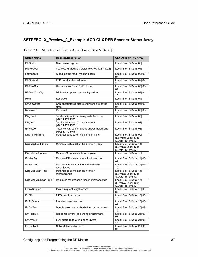
SST-PFB-CLX-RLL User Reference Guide
Configuring and Programming the DP Master 87
©2008 Woodhead Industries Inc. Document Edition: 1.8, Document #: 715-0022, Template Edition: 1.1, Template #: QMS-06-045
Use, duplication or disclosure of this document or any of the information contained herein is subject to the restrictions on page ii of this document.
SSTPFBCLX_Preview_2_Example.ACD CLX PFB Scanner Status Array
Table 23: Structure of Status Area (Local:Slot:S.Data[])
Status Name Meaning/Description CLX Addr (INT16 Array)
PfbStatus Card status register Local: Slot: S.Data [00]
PfbModVer CLXPROFI Module Version (ex. 0x0102 = 1.02) Local: Slot: S.Data [01]
PfbMasSts Global status for all master blocks Local: Slot: S.Data [02].00-07
PfbStnAddr PFB Local station address Local: Slot: S.Data [02].8-15
PfbFmsSts Global status for all FMS blocks Local: Slot: S.Data [03].00-07
PfbMasCntrlCfg DP Master options and configuration Local: Slot: S.Data [03].8-15
Res1 Reserved Local: Slot: S.Data [04]
ErrLanOffline LAN encountered errors and went into offline state
Local: Slot: S.Data [05].00-07
Reserved Reserved Local: Slot: S.Data [05].08-15
DiagConf Total confirmations (to requests from us) (MAS,LAY2,FMS)
Local: Slot: S.Data [06]
DiagInd Total indications (requests to us) (MAS,LAY2,FMS)
Local: Slot: S.Data [07]
ErrNotOk Total Not OK confirmations and/or indications (MAS,LAY2,FMS)
Local: Slot: S.Data [08]
DiagTokHldTime Instantaneous token hold time in Tbits Local: Slot: S.Data [09] (LSW) œ Local: Slot: S.Data [10] (MSW)
DiagMinTokHldTime Minimum Actual token hold time in Tbits Local: Slot: S.Data [11] (LSW) œ Local: Slot: S.Data [12] (MSW)
DiagMasterUpdate Master I/O update cycles completed Local: Slot: S.Data [13]
ErrMasErr Master->DP slave communication errors Local: Slot: S.Data [14].00-07
ErrReConfig Master->DP went offline and had to be reconfigured
Local: Slot: S.Data [14].08-15
DiagMasScanTime Instantaneous master scan time in microseconds
Local: Slot: S.Data [15] (LSW) œ Local: Slot: S.Data [16] (MSW)
DiagMasMaxScanTime Maximum master scan time in microseconds Local: Slot: S.Data [17] (LSW) œ Local: Slot: S.Data [18] (MSW)
ErrInvReqLen Invalid request length errors Local: Slot: S.Data [19].00-07
ErrFifo FIFO overflow errors Local: Slot: S.Data [19].08-15
ErrRxOverun Receive overrun errors Local: Slot: S.Data [20].00-07
ErrDblTok Double token errors (bad wiring or hardware) Local: Slot: S.Data [20].08-15
ErrRespErr Response errors (bad wiring or hardware) Local: Slot: S.Data [21].00-07
ErrSyniErr Syni errors (bad wiring or hardware) Local: Slot: S.Data [21].08-15
ErrNetTout Network timeout errors Local: Slot: S.Data [22].00-07
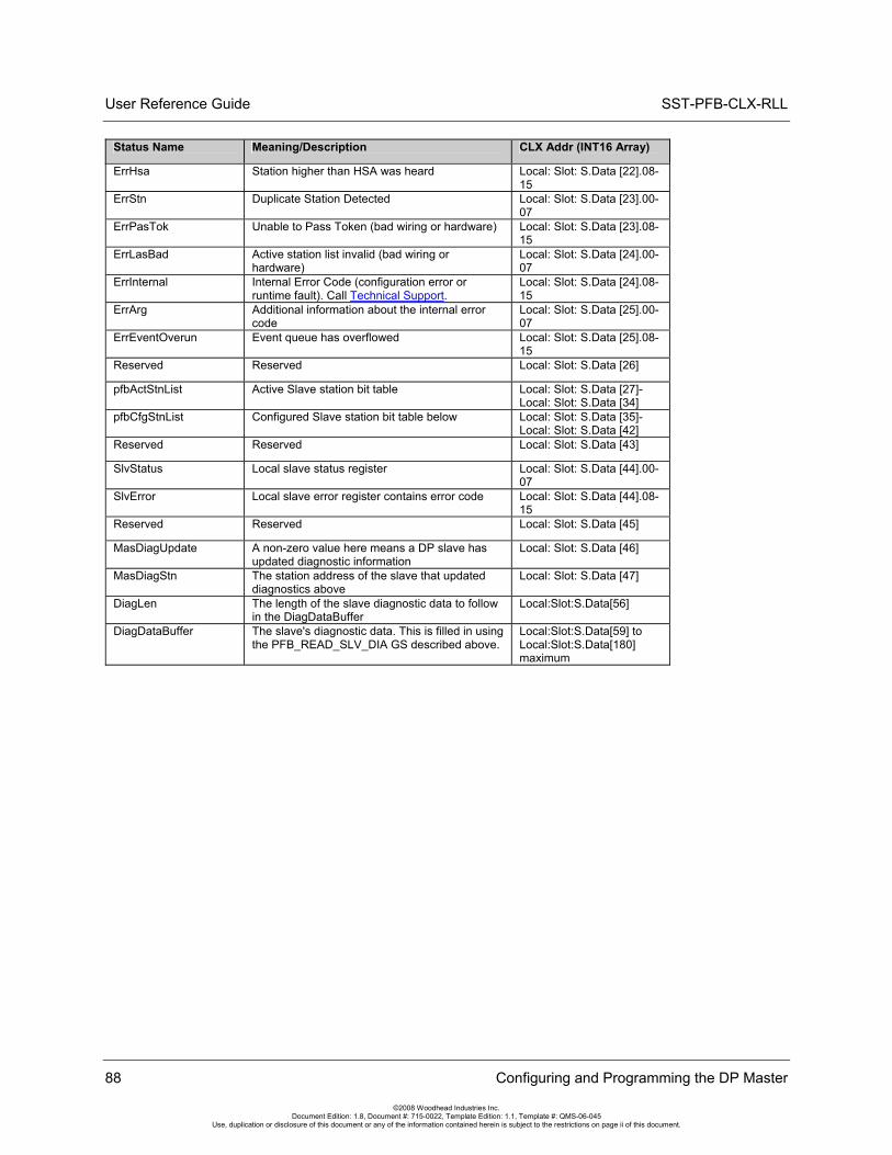
User Reference Guide SST-PFB-CLX-RLL
88 Configuring and Programming the DP Master
©2008 Woodhead Industries Inc. Document Edition: 1.8, Document #: 715-0022, Template Edition: 1.1, Template #: QMS-06-045
Use, duplication or disclosure of this document or any of the information contained herein is subject to the restrictions on page ii of this document.
Status Name Meaning/Description CLX Addr (INT16 Array)
ErrHsa Station higher than HSA was heard Local: Slot: S.Data [22].08-15
ErrStn Duplicate Station Detected Local: Slot: S.Data [23].00-07
ErrPasTok Unable to Pass Token (bad wiring or hardware) Local: Slot: S.Data [23].08-15
ErrLasBad Active station list invalid (bad wiring or hardware)
Local: Slot: S.Data [24].00-07
ErrInternal Internal Error Code (configuration error or runtime fault). Call Technical Support.
Local: Slot: S.Data [24].08-15
ErrArg Additional information about the internal error code
Local: Slot: S.Data [25].00-07
ErrEventOverun Event queue has overflowed Local: Slot: S.Data [25].08-15
Reserved Reserved Local: Slot: S.Data [26]
pfbActStnList Active Slave station bit table Local: Slot: S.Data [27]-Local: Slot: S.Data [34]
pfbCfgStnList Configured Slave station bit table below Local: Slot: S.Data [35]-Local: Slot: S.Data [42]
Reserved Reserved Local: Slot: S.Data [43]
SlvStatus Local slave status register Local: Slot: S.Data [44].00-07
SlvError Local slave error register contains error code Local: Slot: S.Data [44].08-15
Reserved Reserved Local: Slot: S.Data [45]
MasDiagUpdate A non-zero value here means a DP slave has updated diagnostic information
Local: Slot: S.Data [46]
MasDiagStn The station address of the slave that updated diagnostics above
Local: Slot: S.Data [47]
DiagLen The length of the slave diagnostic data to follow in the DiagDataBuffer
Local:Slot:S.Data[56]
DiagDataBuffer The slave's diagnostic data. This is filled in using the PFB_READ_SLV_DIA GS described above.
Local:Slot:S.Data[59] to Local:Slot:S.Data[180] maximum
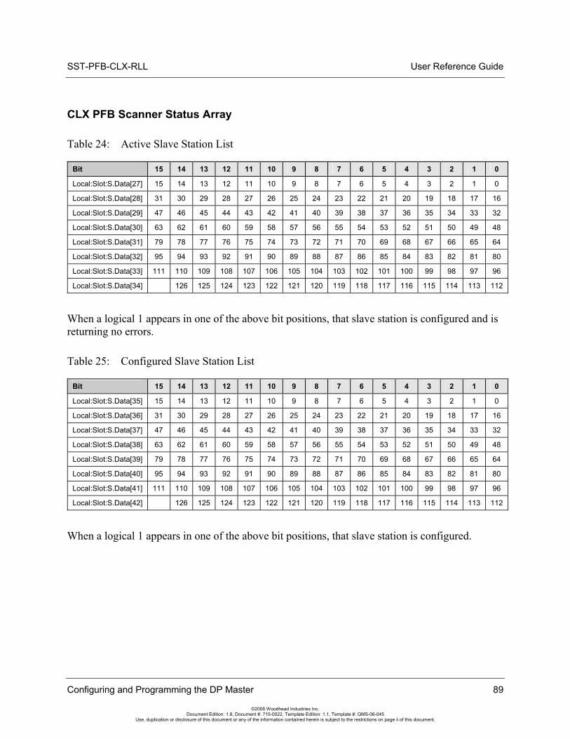
SST-PFB-CLX-RLL User Reference Guide
Configuring and Programming the DP Master 89
©2008 Woodhead Industries Inc. Document Edition: 1.8, Document #: 715-0022, Template Edition: 1.1, Template #: QMS-06-045
Use, duplication or disclosure of this document or any of the information contained herein is subject to the restrictions on page ii of this document.
CLX PFB Scanner Status Array
Table 24: Active Slave Station List
Bit 15 14 13 12 11 10 9 8 7 6 5 4 3 2 1 0
Local:Slot:S.Data[27] 15 14 13 12 11 10 9 8 7 6 5 4 3 2 1 0
Local:Slot:S.Data[28] 31 30 29 28 27 26 25 24 23 22 21 20 19 18 17 16
Local:Slot:S.Data[29] 47 46 45 44 43 42 41 40 39 38 37 36 35 34 33 32
Local:Slot:S.Data[30] 63 62 61 60 59 58 57 56 55 54 53 52 51 50 49 48
Local:Slot:S.Data[31] 79 78 77 76 75 74 73 72 71 70 69 68 67 66 65 64
Local:Slot:S.Data[32] 95 94 93 92 91 90 89 88 87 86 85 84 83 82 81 80
Local:Slot:S.Data[33] 111 110 109 108 107 106 105 104 103 102 101 100 99 98 97 96
Local:Slot:S.Data[34] 126 125 124 123 122 121 120 119 118 117 116 115 114 113 112
When a logical 1 appears in one of the above bit positions, that slave station is configured and is returning no errors.
Table 25: Configured Slave Station List
Bit 15 14 13 12 11 10 9 8 7 6 5 4 3 2 1 0
Local:Slot:S.Data[35] 15 14 13 12 11 10 9 8 7 6 5 4 3 2 1 0
Local:Slot:S.Data[36] 31 30 29 28 27 26 25 24 23 22 21 20 19 18 17 16
Local:Slot:S.Data[37] 47 46 45 44 43 42 41 40 39 38 37 36 35 34 33 32
Local:Slot:S.Data[38] 63 62 61 60 59 58 57 56 55 54 53 52 51 50 49 48
Local:Slot:S.Data[39] 79 78 77 76 75 74 73 72 71 70 69 68 67 66 65 64
Local:Slot:S.Data[40] 95 94 93 92 91 90 89 88 87 86 85 84 83 82 81 80
Local:Slot:S.Data[41] 111 110 109 108 107 106 105 104 103 102 101 100 99 98 97 96
Local:Slot:S.Data[42] 126 125 124 123 122 121 120 119 118 117 116 115 114 113 112
When a logical 1 appears in one of the above bit positions, that slave station is configured.
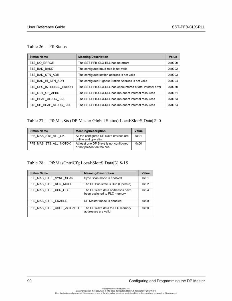
User Reference Guide SST-PFB-CLX-RLL
90 Configuring and Programming the DP Master
©2008 Woodhead Industries Inc. Document Edition: 1.8, Document #: 715-0022, Template Edition: 1.1, Template #: QMS-06-045
Use, duplication or disclosure of this document or any of the information contained herein is subject to the restrictions on page ii of this document.
Table 26: PfbStatus
Status Name Meaning/Description Value
STS_NO_ERROR The SST-PFB-CLX-RLL has no errors 0x0000
STS_BAD_BAUD The configured baud rate is not valid 0x0002
STS_BAD_STN_ADR The configured station address is not valid 0x0003
STS_BAD_HI_STN_ADR The configured Highest Station Address is not valid 0x0004
STS_CFG_INTERNAL_ERROR The SST-PFB-CLX-RLL has encountered a fatal internal error 0x0080
STS_OUT_OF_APBS The SST-PFB-CLX-RLL has run out of internal resources 0x0081
STS_HEAP_ALLOC_FAIL The SST-PFB-CLX-RLL has run out of internal resources 0x0083
STS_SH_HEAP_ALLOC_FAIL The SST-PFB-CLX-RLL has run out of internal resources 0x0084
Table 27: PfbMasSts (DP Master Global Status) Local:Slot:S.Data[2].0
Status Name Meaning/Description Value PFB_MAS_STS_ALL_OK All the configured DP slave devices are
online and operating 0x01
PFB_MAS_STS_ALL_NOTOK At least one DP Slave is not configured or not present on the bus
0x00
Table 28: PfbMasCntrlCfg Local:Slot:S.Data[3].8-15
Status Name Meaning/Description Value PFB_MAS_CTRL_SYNC_SCAN Sync Scan mode is enabled 0x01
PFB_MAS_CTRL_RUN_MODE The DP Bus state is Run (Operate) 0x02
PFB_MAS_CTRL_USR_OFS The DP slave data addresses have been assigned to PLC memory
0x04
PFB_MAS_CTRL_ENABLE DP Master mode is enabled 0x08
PFB_MAS_CTRL_ADDR_ASIGNED The DP slave data to PLC memory addresses are valid
0x80
SST-PFB-CLX-RLL User Reference Guide
Configuring and Programming the DP Master 91
©2008 Woodhead Industries Inc. Document Edition: 1.8, Document #: 715-0022, Template Edition: 1.1, Template #: QMS-06-045
Use, duplication or disclosure of this document or any of the information contained herein is subject to the restrictions on page ii of this document.
5.10 Making Changes to the CLX Configuration File While the PROFIBUS Card is Online 1. Put the PLC into PROG mode.
2. Connect serially to the module via the PROFIBUS Configuration Tool.
3. Issue the Offline command by right-clicking on the Master and selecting the Offline command.
4. Edit the ControlLogix file.
5. Download the PLC program.
6. Put the PLC into RUN.
User Reference Guide SST-PFB-CLX-RLL
92 Configuring and Programming the DP Master
©2008 Woodhead Industries Inc. Document Edition: 1.8, Document #: 715-0022, Template Edition: 1.1, Template #: QMS-06-045
Use, duplication or disclosure of this document or any of the information contained herein is subject to the restrictions on page ii of this document.
SST-PFB-CLX-RLL User Reference Guide
6 System Diagnostics
Chapter Sections:
• PFB Status Register
• Diagnostic Counters
• Summary of Diagnostic Locations
Note The scanner maintains a variety of diagnostic information in its Status area from Local:Slot: S.Data[0] to Local:Slot: S.Data[180].
System Diagnostics 93
©2008 Woodhead Industries Inc. Document Edition: 1.8, Document #: 715-0022, Template Edition: 1.1, Template #: QMS-06-045
Use, duplication or disclosure of this document or any of the information contained herein is subject to the restrictions on page ii of this document.
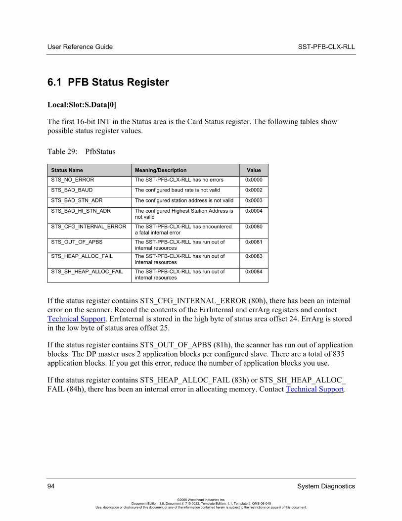
User Reference Guide SST-PFB-CLX-RLL
94 System Diagnostics
©2008 Woodhead Industries Inc. Document Edition: 1.8, Document #: 715-0022, Template Edition: 1.1, Template #: QMS-06-045
Use, duplication or disclosure of this document or any of the information contained herein is subject to the restrictions on page ii of this document.
6.1 PFB Status Register
Local:Slot:S.Data[0]
The first 16-bit INT in the Status area is the Card Status register. The following tables show possible status register values.
Table 29: PfbStatus
Status Name Meaning/Description Value
STS_NO_ERROR The SST-PFB-CLX-RLL has no errors 0x0000
STS_BAD_BAUD The configured baud rate is not valid 0x0002
STS_BAD_STN_ADR The configured station address is not valid 0x0003
STS_BAD_HI_STN_ADR The configured Highest Station Address is not valid
0x0004
STS_CFG_INTERNAL_ERROR The SST-PFB-CLX-RLL has encountered a fatal internal error
0x0080
STS_OUT_OF_APBS The SST-PFB-CLX-RLL has run out of internal resources
0x0081
STS_HEAP_ALLOC_FAIL The SST-PFB-CLX-RLL has run out of internal resources
0x0083
STS_SH_HEAP_ALLOC_FAIL The SST-PFB-CLX-RLL has run out of internal resources
0x0084
If the status register contains STS_CFG_INTERNAL_ERROR (80h), there has been an internal error on the scanner. Record the contents of the ErrInternal and errArg registers and contact Technical Support. ErrInternal is stored in the high byte of status area offset 24. ErrArg is stored in the low byte of status area offset 25.
If the status register contains STS_OUT_OF_APBS (81h), the scanner has run out of application blocks. The DP master uses 2 application blocks per configured slave. There are a total of 835 application blocks. If you get this error, reduce the number of application blocks you use.
If the status register contains STS_HEAP_ALLOC_FAIL (83h) or STS_SH_HEAP_ALLOC_ FAIL (84h), there has been an internal error in allocating memory. Contact Technical Support.
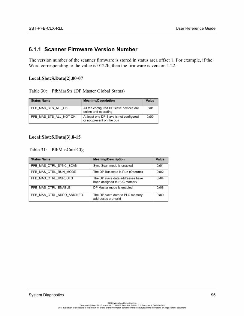
SST-PFB-CLX-RLL User Reference Guide
System Diagnostics 95
©2008 Woodhead Industries Inc. Document Edition: 1.8, Document #: 715-0022, Template Edition: 1.1, Template #: QMS-06-045
Use, duplication or disclosure of this document or any of the information contained herein is subject to the restrictions on page ii of this document.
6.1.1 Scanner Firmware Version Number
The version number of the scanner firmware is stored in status area offset 1. For example, if the Word corresponding to the value is 0122h, then the firmware is version 1.22.
Local:Slot:S.Data[2].00-07
Table 30: PfbMasSts (DP Master Global Status)
Status Name Meaning/Description Value
PFB_MAS_STS_ALL_OK All the configured DP slave devices are online and operating
0x01
PFB_MAS_STS_ALL_NOT OK At least one DP Slave is not configured or not present on the bus
0x00
Local:Slot:S.Data[3].8-15
Table 31: PfbMasCntrlCfg
Status Name Meaning/Description Value
PFB_MAS_CTRL_SYNC_SCAN Sync Scan mode is enabled 0x01
PFB_MAS_CTRL_RUN_MODE The DP Bus state is Run (Operate) 0x02
PFB_MAS_CTRL_USR_OFS The DP slave data addresses have been assigned to PLC memory
0x04
PFB_MAS_CTRL_ENABLE DP Master mode is enabled 0x08
PFB_MAS_CTRL_ADDR_ASIGNED The DP slave data to PLC memory addresses are valid
0x80
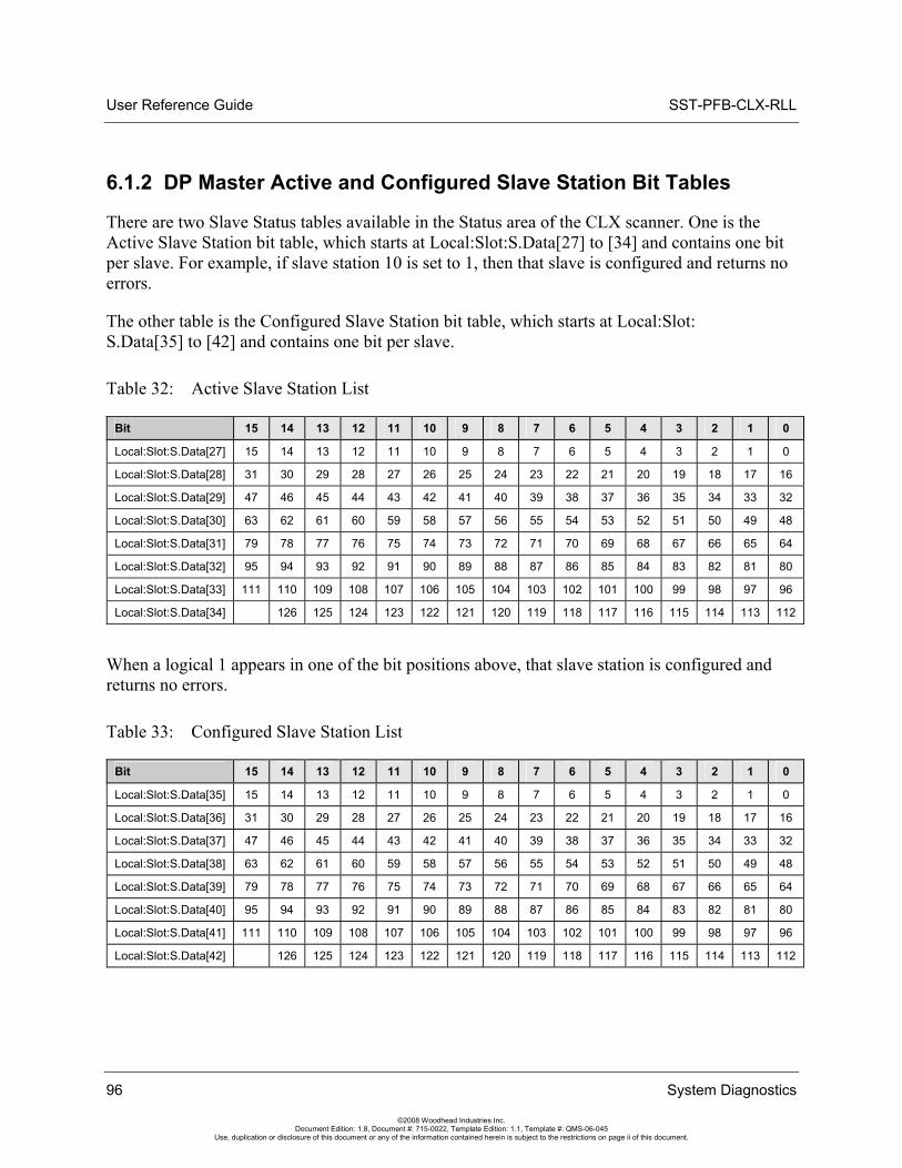
User Reference Guide SST-PFB-CLX-RLL
96 System Diagnostics
©2008 Woodhead Industries Inc. Document Edition: 1.8, Document #: 715-0022, Template Edition: 1.1, Template #: QMS-06-045
Use, duplication or disclosure of this document or any of the information contained herein is subject to the restrictions on page ii of this document.
6.1.2 DP Master Active and Configured Slave Station Bit Tables
There are two Slave Status tables available in the Status area of the CLX scanner. One is the Active Slave Station bit table, which starts at Local:Slot:S.Data[27] to [34] and contains one bit per slave. For example, if slave station 10 is set to 1, then that slave is configured and returns no errors.
The other table is the Configured Slave Station bit table, which starts at Local:Slot: S.Data[35] to [42] and contains one bit per slave.
Table 32: Active Slave Station List
Bit 15 14 13 12 11 10 9 8 7 6 5 4 3 2 1 0
Local:Slot:S.Data[27] 15 14 13 12 11 10 9 8 7 6 5 4 3 2 1 0
Local:Slot:S.Data[28] 31 30 29 28 27 26 25 24 23 22 21 20 19 18 17 16
Local:Slot:S.Data[29] 47 46 45 44 43 42 41 40 39 38 37 36 35 34 33 32
Local:Slot:S.Data[30] 63 62 61 60 59 58 57 56 55 54 53 52 51 50 49 48
Local:Slot:S.Data[31] 79 78 77 76 75 74 73 72 71 70 69 68 67 66 65 64
Local:Slot:S.Data[32] 95 94 93 92 91 90 89 88 87 86 85 84 83 82 81 80
Local:Slot:S.Data[33] 111 110 109 108 107 106 105 104 103 102 101 100 99 98 97 96
Local:Slot:S.Data[34] 126 125 124 123 122 121 120 119 118 117 116 115 114 113 112
When a logical 1 appears in one of the bit positions above, that slave station is configured and returns no errors.
Table 33: Configured Slave Station List
Bit 15 14 13 12 11 10 9 8 7 6 5 4 3 2 1 0
Local:Slot:S.Data[35] 15 14 13 12 11 10 9 8 7 6 5 4 3 2 1 0
Local:Slot:S.Data[36] 31 30 29 28 27 26 25 24 23 22 21 20 19 18 17 16
Local:Slot:S.Data[37] 47 46 45 44 43 42 41 40 39 38 37 36 35 34 33 32
Local:Slot:S.Data[38] 63 62 61 60 59 58 57 56 55 54 53 52 51 50 49 48
Local:Slot:S.Data[39] 79 78 77 76 75 74 73 72 71 70 69 68 67 66 65 64
Local:Slot:S.Data[40] 95 94 93 92 91 90 89 88 87 86 85 84 83 82 81 80
Local:Slot:S.Data[41] 111 110 109 108 107 106 105 104 103 102 101 100 99 98 97 96
Local:Slot:S.Data[42] 126 125 124 123 122 121 120 119 118 117 116 115 114 113 112
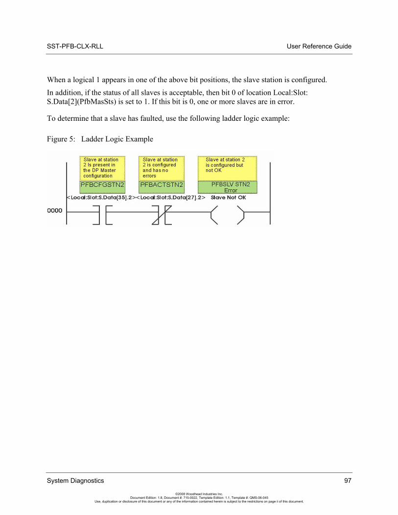
SST-PFB-CLX-RLL User Reference Guide
When a logical 1 appears in one of the above bit positions, the slave station is configured.
In addition, if the status of all slaves is acceptable, then bit 0 of location Local:Slot: S.Data[2](PfbMasSts) is set to 1. If this bit is 0, one or more slaves are in error.
To determine that a slave has faulted, use the following ladder logic example:
Figure 5: Ladder Logic Example
System Diagnostics 97
©2008 Woodhead Industries Inc. Document Edition: 1.8, Document #: 715-0022, Template Edition: 1.1, Template #: QMS-06-045
Use, duplication or disclosure of this document or any of the information contained herein is subject to the restrictions on page ii of this document.
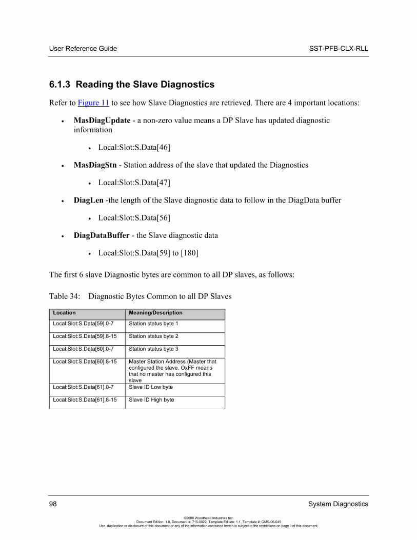
User Reference Guide SST-PFB-CLX-RLL
98 System Diagnostics
©2008 Woodhead Industries Inc. Document Edition: 1.8, Document #: 715-0022, Template Edition: 1.1, Template #: QMS-06-045
Use, duplication or disclosure of this document or any of the information contained herein is subject to the restrictions on page ii of this document.
6.1.3 Reading the Slave Diagnostics
Refer to Figure 11 to see how Slave Diagnostics are retrieved. There are 4 important locations:
• MasDiagUpdate - a non-zero value means a DP Slave has updated diagnostic information
• Local:Slot:S.Data[46]
• MasDiagStn - Station address of the slave that updated the Diagnostics
• Local:Slot:S.Data[47]
• DiagLen -the length of the Slave diagnostic data to follow in the DiagData buffer
• Local:Slot:S.Data[56]
• DiagDataBuffer - the Slave diagnostic data
• Local:Slot:S.Data[59] to [180]
The first 6 slave Diagnostic bytes are common to all DP slaves, as follows:
Table 34: Diagnostic Bytes Common to all DP Slaves
Location Meaning/Description
Local:Slot:S.Data[59].0-7 Station status byte 1
Local:Slot:S.Data[59].8-15 Station status byte 2
Local:Slot:S.Data[60].0-7 Station status byte 3
Local:Slot:S.Data[60].8-15 Master Station Address (Master that configured the slave. OxFF means that no master has configured this slave
Local:Slot:S.Data[61].0-7 Slave ID Low byte
Local:Slot:S.Data[61].8-15 Slave ID High byte
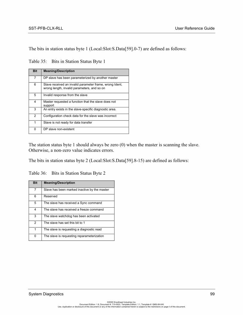
SST-PFB-CLX-RLL User Reference Guide
System Diagnostics 99
©2008 Woodhead Industries Inc. Document Edition: 1.8, Document #: 715-0022, Template Edition: 1.1, Template #: QMS-06-045
Use, duplication or disclosure of this document or any of the information contained herein is subject to the restrictions on page ii of this document.
The bits in station status byte 1 (Local:Slot:S.Data[59].0-7) are defined as follows:
Table 35: Bits in Station Status Byte 1
Bit Meaning/Description
7 DP slave has been parameterized by another master
6 Slave received an invalid parameter frame, wrong Ident, wrong length, invalid parameters, and so on
5 Invalid response from the slave
4 Master requested a function that the slave does not support
3 An entry exists in the slave-specific diagnostic area.
2 Configuration check data for the slave was incorrect
1 Slave is not ready for data transfer
0 DP slave non-existent
The station status byte 1 should always be zero (0) when the master is scanning the slave. Otherwise, a non-zero value indicates errors.
The bits in station status byte 2 (Local:Slot:S.Data[59].8-15) are defined as follows:
Table 36: Bits in Station Status Byte 2
Bit Meaning/Description
7 Slave has been marked inactive by the master
6 Reserved
5 The slave has received a Sync command
4 The slave has received a freeze command
3 The slave watchdog has been activated
2 The slave has set this bit to 1
1 The slave is requesting a diagnostic read
0 The slave is requesting reparameterization
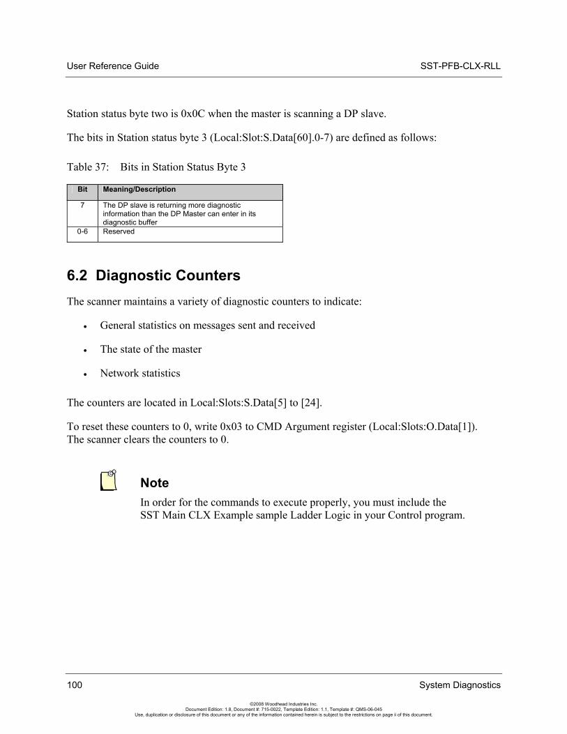
User Reference Guide SST-PFB-CLX-RLL
Station status byte two is 0x0C when the master is scanning a DP slave.
The bits in Station status byte 3 (Local:Slot:S.Data[60].0-7) are defined as follows:
Table 37: Bits in Station Status Byte 3
Bit Meaning/Description
7 The DP slave is returning more diagnostic information than the DP Master can enter in its diagnostic buffer
0-6 Reserved
6.2 Diagnostic Counters The scanner maintains a variety of diagnostic counters to indicate:
• General statistics on messages sent and received
• The state of the master
• Network statistics
The counters are located in Local:Slots:S.Data[5] to [24].
To reset these counters to 0, write 0x03 to CMD Argument register (Local:Slots:O.Data[1]). The scanner clears the counters to 0.
Note In order for the commands to execute properly, you must include the SST Main CLX Example sample Ladder Logic in your Control program.
100 System Diagnostics
©2008 Woodhead Industries Inc. Document Edition: 1.8, Document #: 715-0022, Template Edition: 1.1, Template #: QMS-06-045
Use, duplication or disclosure of this document or any of the information contained herein is subject to the restrictions on page ii of this document.
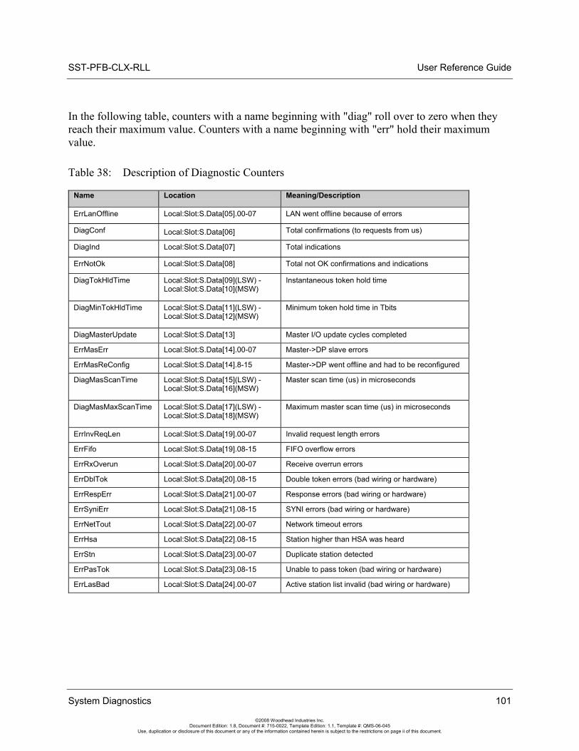
SST-PFB-CLX-RLL User Reference Guide
System Diagnostics 101
©2008 Woodhead Industries Inc. Document Edition: 1.8, Document #: 715-0022, Template Edition: 1.1, Template #: QMS-06-045
Use, duplication or disclosure of this document or any of the information contained herein is subject to the restrictions on page ii of this document.
In the following table, counters with a name beginning with "diag" roll over to zero when they reach their maximum value. Counters with a name beginning with "err" hold their maximum value.
Table 38: Description of Diagnostic Counters
Name Location Meaning/Description
ErrLanOffline Local:Slot:S.Data[05].00-07 LAN went offline because of errors
DiagConf Local:Slot:S.Data[06] Total confirmations (to requests from us)
DiagInd Local:Slot:S.Data[07] Total indications
ErrNotOk Local:Slot:S.Data[08] Total not OK confirmations and indications
DiagTokHldTime Local:Slot:S.Data[09](LSW) -Local:Slot:S.Data[10](MSW)
Instantaneous token hold time
DiagMinTokHldTime Local:Slot:S.Data[11](LSW) -Local:Slot:S.Data[12](MSW)
Minimum token hold time in Tbits
DiagMasterUpdate Local:Slot:S.Data[13] Master I/O update cycles completed
ErrMasErr Local:Slot:S.Data[14].00-07 Master->DP slave errors
ErrMasReConfig Local:Slot:S.Data[14].8-15 Master->DP went offline and had to be reconfigured
DiagMasScanTime Local:Slot:S.Data[15](LSW) -Local:Slot:S.Data[16](MSW)
Master scan time (us) in microseconds
DiagMasMaxScanTime Local:Slot:S.Data[17](LSW) -Local:Slot:S.Data[18](MSW)
Maximum master scan time (us) in microseconds
ErrInvReqLen Local:Slot:S.Data[19].00-07 Invalid request length errors
ErrFifo Local:Slot:S.Data[19].08-15 FIFO overflow errors
ErrRxOverun Local:Slot:S.Data[20].00-07 Receive overrun errors
ErrDblTok Local:Slot:S.Data[20].08-15 Double token errors (bad wiring or hardware)
ErrRespErr Local:Slot:S.Data[21].00-07 Response errors (bad wiring or hardware)
ErrSyniErr Local:Slot:S.Data[21].08-15 SYNI errors (bad wiring or hardware)
ErrNetTout Local:Slot:S.Data[22].00-07 Network timeout errors
ErrHsa Local:Slot:S.Data[22].08-15 Station higher than HSA was heard
ErrStn Local:Slot:S.Data[23].00-07 Duplicate station detected
ErrPasTok Local:Slot:S.Data[23].08-15 Unable to pass token (bad wiring or hardware)
ErrLasBad Local:Slot:S.Data[24].00-07 Active station list invalid (bad wiring or hardware)
User Reference Guide SST-PFB-CLX-RLL
102 System Diagnostics
©2008 Woodhead Industries Inc. Document Edition: 1.8, Document #: 715-0022, Template Edition: 1.1, Template #: QMS-06-045
Use, duplication or disclosure of this document or any of the information contained herein is subject to the restrictions on page ii of this document.
6.2.1 General Statistics
These counters relate to the overall operation of the scanner on PROFIBUS.
The following is a list of general counter statistics:
• The ErrLanOffline counter, register Local:Slot:S.Data[05].0-7, increments when the LAN encounters errors and goes offline
• The DiagConf counter, register Local:Slot:S.Data[06], counts total confirmations, that is, good replies to messages that this station has generated
• The DiagInd counter, register Local:Slot:S.Data[07], counts total indications, that is, unsolicited messages to this station
• The ErrNotOk counter, register Local:Slot:S.Data[08], counts the Total Not OK confirmations and indications, that is, total bad replies and bad unsolicited messages (indications)
• The scanner stores the instantaneous token hold time, in Tbits, in DiagTokHldTime, registers Local:Slot:S.Data[09](LSW) and Local:Slot:S.Data[10](MSW). This is the time available to send messages when the scanner gets the token.
• The scanner stores the minimum actual token hold time, in Tbits, in DiagMinTokHldTime, registers Local:Slot:S.Data[11](LSW) and Local:Slot: S.Data[12](MSW). This time is the minimum value of diagTokHldTime. If this number is 0, you may need to increase the target token rotation time in your configuration.
To increase the target token rotation time, do the following:
1. Open your DP Master Configuration in the Configuration Tool.
2. Select and highlight the PROFIBUS.DP.
3. Right-click and select Properties from the shortcut menu that displays.
4. Select the Timing tab in the Network Dialog box.
5. Select the Token Rotation Time checkbox.
6. Enter the new value (the sum of ALL masters or Active Station’s token rotation time) in the Token Rotation Time field.
SST-PFB-CLX-RLL User Reference Guide
6.2.2 DP Master Statistics
These counters relate to the operation of the scanner as a DP master.
The following is a list of DP Master Statistics:
• The DiagMasterUpdate counter, register Local:Slot:S.Data[13], is the number of Master I/O update cycles completed
• The ErrMasErr counter, the low byte of register Local:Slot:S.Data[14], bits 00-07, is the number of DP master to DP slave communication errors. It increments anytime the message failed because of retries exceeded, and so on.
• The ErrMasReConfig counter, the high byte of register Local:Slot:S.Data[14], bits 08-15, is the number of times a DP slave went offline and had to be reconfigured, that is, the scanner was actively updating a node and got a faulty message
• The DiagMasScanTime register, registers Local:Slot:S.Data[15](LSW) and Local:Slot:S.Data[16](MSW). It contains the instantaneous master scan time in micro-seconds, that is, the time to scan all the slaves assigned to this master. The scanner adds 100 micro-seconds to the measured time to allow for overhead in starting the timer, and so on.
Note The DiagMasScanTime and DiagMasMaxScanTime registers do not reflect the real scan time when the master is in Host-Sync- mode and the RPI is higher than the predefined scan time. See the typical scan time given in your SST PROFIBUS Master configuration. As a safety margin, the maximum Master scan time should always be 3 times less than the RPI time. Therefore, if the DiagMasMaxScanTime is higher than your RPI time, you will miss slave updates each PROFIBUS scan.
The DiagMasMaxScanTime registers contains the maximum value that DiagMasScanTime reached since it was last cleared:
Local:Slot:S.Data[17](LSW) to Local:Slot:S.Data[18](MSW)
System Diagnostics 103
©2008 Woodhead Industries Inc. Document Edition: 1.8, Document #: 715-0022, Template Edition: 1.1, Template #: QMS-06-045
Use, duplication or disclosure of this document or any of the information contained herein is subject to the restrictions on page ii of this document.
User Reference Guide SST-PFB-CLX-RLL
104 System Diagnostics
©2008 Woodhead Industries Inc. Document Edition: 1.8, Document #: 715-0022, Template Edition: 1.1, Template #: QMS-06-045
Use, duplication or disclosure of this document or any of the information contained herein is subject to the restrictions on page ii of this document.
6.2.3 ASPC2 PROFIBUS Controller Statistics
The ASPC2 LAN controller maintains the following counters. They are all 1 byte long. When these counters reach 255, they hold at 255 until cleared.
The ErrInvReqLen Counter
The low byte of register Local:Slot:S.Data[19], bits 0-7, counts invalid request length errors. These errors occur when the scanner software gives the LAN controller a message that is too long. This is an internal error and should never occur.
The ErrFifo Counter
The high byte of register Local:Slot:S.Data[19], bits 8-15, counts FIFO overflow errors. These errors occur when the LAN controller cannot write to memory fast enough. This is an internal error and should never occur.
The ErrRxOverun Counter
The low byte of register Local:Slot:S.Data[20], bits 0-7, counts receive overrun errors. This is an internal error and should never occur.
The ErrDblTok Counter
The high byte of register Local:Slot:S.Data[20], bits 8-15, counts double token errors. These errors may occur when more than one node thinks it has the token or there are wiring errors, duplicate nodes, and so on. The scanner withdraws to the “not hold token” state (decides it doesn't have the token) and waits until it gets the token passed to it again.
The ErrRespErr Counter
The low byte of register Local:Slot:S.Data[21], bits 0-7, counts response errors when a message fails or there is no response from the destination. This error may be due to bad hardware or faulty wiring.
The ErrSyniErr Counter
The high byte of register Local:Slot:S.Data[21], bits 8-15, indicates general network errors. These errors occur when there are problems on the network, but before you get a network timeout error.
SST-PFB-CLX-RLL User Reference Guide
System Diagnostics 105
©2008 Woodhead Industries Inc. Document Edition: 1.8, Document #: 715-0022, Template Edition: 1.1, Template #: QMS-06-045
Use, duplication or disclosure of this document or any of the information contained herein is subject to the restrictions on page ii of this document.
The ErrNetTout Counter
The low byte of register Local:Slot:S.Data[22], bits 0-7, counts network timeout errors. These errors occur when the network is dead. If a timeout occurs, the scanner enters the claim token state.
The ErrHsa Counter
The high byte of register Local:Slot:S.Data[22], bits 8-15, increments when a station higher than the set high station address is heard. If the scanner is going online, it increments the counter and stays offline.
The ErrStn Counter
The low byte of register Local:Slot:S.Data[23], bits 0-7, increments when a duplicate station is detected. If this error occurs when the scanner is going online, the scanner increments the errStn counter and stays offline.
The ErrPasTok Counter
The high byte of register Local:Slot:S.Data[23], bits 8-15, increments when the scanner is unable to pass the token. This is usually caused by bad wiring (shorted) or other hardware problems. The scanner tries to pass the token, fails to hear its own token pass message, and puts itself offline.
The ErrLasBad Counter
The low byte of register Local:Slot:S.Data [24], bits 0-7, increments when the active station list on the ASPC2 LAN controller is invalid because of multiple network errors. This error is caused by bad wiring or hardware.
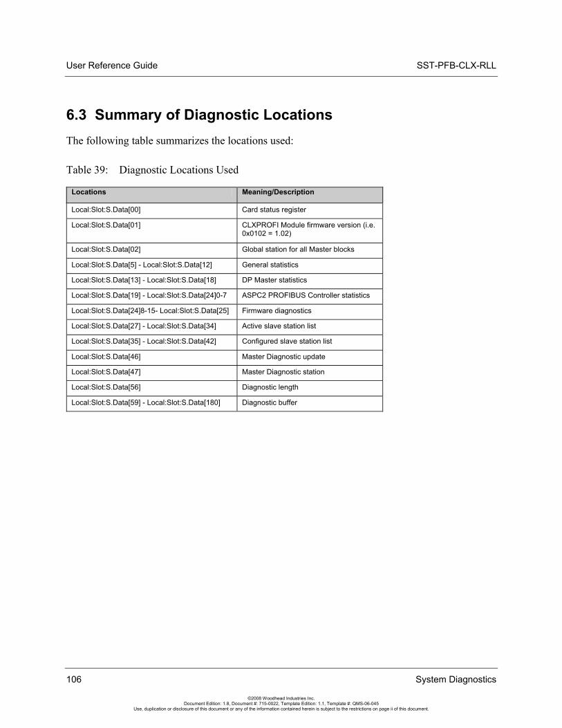
User Reference Guide SST-PFB-CLX-RLL
106 System Diagnostics
©2008 Woodhead Industries Inc. Document Edition: 1.8, Document #: 715-0022, Template Edition: 1.1, Template #: QMS-06-045
Use, duplication or disclosure of this document or any of the information contained herein is subject to the restrictions on page ii of this document.
6.3 Summary of Diagnostic Locations The following table summarizes the locations used:
Table 39: Diagnostic Locations Used
Locations Meaning/Description
Local:Slot:S.Data[00] Card status register
Local:Slot:S.Data[01] CLXPROFI Module firmware version (i.e. 0x0102 = 1.02)
Local:Slot:S.Data[02] Global station for all Master blocks
Local:Slot:S.Data[5] - Local:Slot:S.Data[12] General statistics
Local:Slot:S.Data[13] - Local:Slot:S.Data[18] DP Master statistics
Local:Slot:S.Data[19] - Local:Slot:S.Data[24]0-7 ASPC2 PROFIBUS Controller statistics
Local:Slot:S.Data[24]8-15- Local:Slot:S.Data[25] Firmware diagnostics
Local:Slot:S.Data[27] - Local:Slot:S.Data[34] Active slave station list
Local:Slot:S.Data[35] - Local:Slot:S.Data[42] Configured slave station list
Local:Slot:S.Data[46] Master Diagnostic update
Local:Slot:S.Data[47] Master Diagnostic station
Local:Slot:S.Data[56] Diagnostic length
Local:Slot:S.Data[59] - Local:Slot:S.Data[180] Diagnostic buffer
SST-PFB-CLX-RLL User Reference Guide
DP Master Application Examples 107
©2008 Woodhead Industries Inc. Document Edition: 1.8, Document #: 715-0022, Template Edition: 1.1, Template #: QMS-06-045
Use, duplication or disclosure of this document or any of the information contained herein is subject to the restrictions on page ii of this document.
7 DP Master Application Examples
Chapter Sections:
• Addressing
• Main CLX Example
• Reading Slave Diagnostics
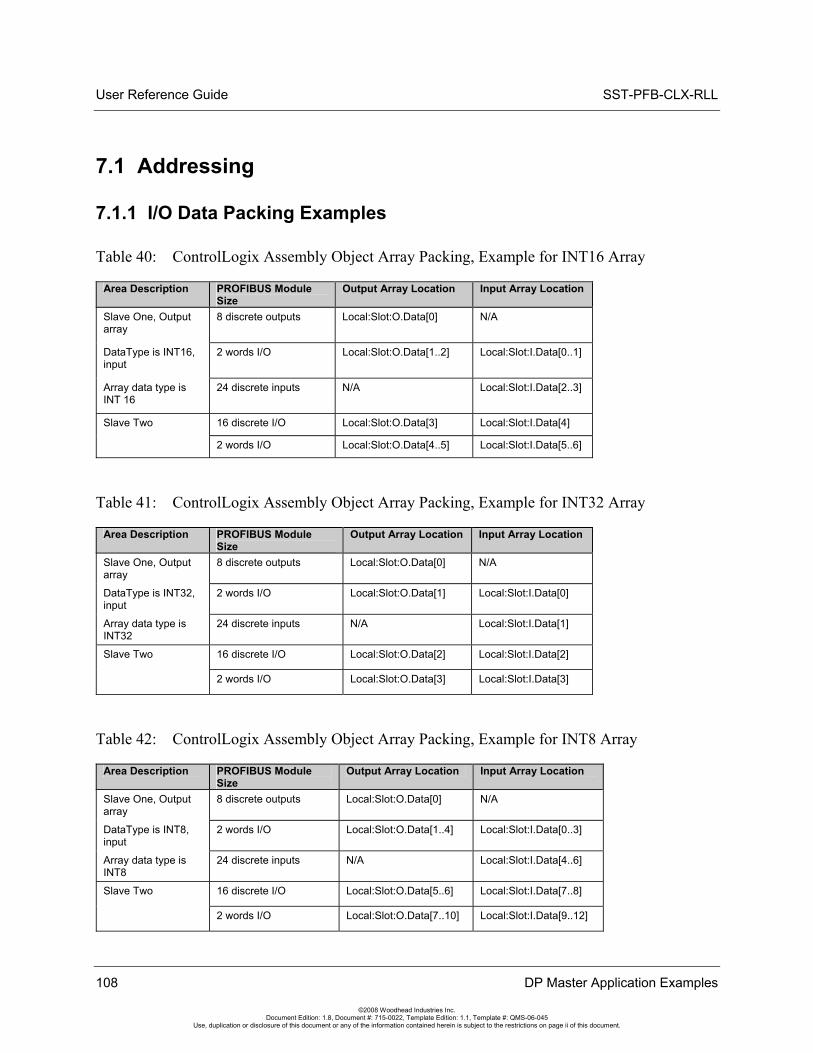
User Reference Guide SST-PFB-CLX-RLL
108 DP Master Application Examples
©2008 Woodhead Industries Inc. Document Edition: 1.8, Document #: 715-0022, Template Edition: 1.1, Template #: QMS-06-045
Use, duplication or disclosure of this document or any of the information contained herein is subject to the restrictions on page ii of this document.
7.1 Addressing
7.1.1 I/O Data Packing Examples
Table 40: ControlLogix Assembly Object Array Packing, Example for INT16 Array
Area Description PROFIBUS Module Size
Output Array Location Input Array Location
Slave One, Output array
8 discrete outputs Local:Slot:O.Data[0] N/A
DataType is INT16, input
2 words I/O Local:Slot:O.Data[1..2] Local:Slot:I.Data[0..1]
Array data type is INT 16
24 discrete inputs N/A Local:Slot:I.Data[2..3]
16 discrete I/O Local:Slot:O.Data[3] Local:Slot:I.Data[4] Slave Two
2 words I/O Local:Slot:O.Data[4..5] Local:Slot:I.Data[5..6]
Table 41: ControlLogix Assembly Object Array Packing, Example for INT32 Array
Area Description PROFIBUS Module Size
Output Array Location Input Array Location
Slave One, Output array
8 discrete outputs Local:Slot:O.Data[0] N/A
DataType is INT32, input
2 words I/O Local:Slot:O.Data[1] Local:Slot:I.Data[0]
Array data type is INT32
24 discrete inputs N/A Local:Slot:I.Data[1]
16 discrete I/O Local:Slot:O.Data[2] Local:Slot:I.Data[2] Slave Two
2 words I/O Local:Slot:O.Data[3] Local:Slot:I.Data[3]
Table 42: ControlLogix Assembly Object Array Packing, Example for INT8 Array
Area Description PROFIBUS Module Size
Output Array Location Input Array Location
Slave One, Output array
8 discrete outputs Local:Slot:O.Data[0] N/A
DataType is INT8, input
2 words I/O Local:Slot:O.Data[1..4] Local:Slot:I.Data[0..3]
Array data type is INT8
24 discrete inputs N/A Local:Slot:I.Data[4..6]
16 discrete I/O Local:Slot:O.Data[5..6] Local:Slot:I.Data[7..8] Slave Two
2 words I/O Local:Slot:O.Data[7..10] Local:Slot:I.Data[9..12]
SST-PFB-CLX-RLL User Reference Guide
7.2 Main CLX Example Handshaking between the Host CPU and the scanner module is done using the CMD Control (Local:Slot: O.Data[0]), CMD Argument (Local:Slot: O.Data[1]), and CMD Reply (Local:Slot: I.Data[1]) registers.
The following example shows how to interface with the card:
• Check to see if the Card is offline by reading the ModuleStatus register (Local:Slot: I.Data[0]). If it is (0xE0), wait one 1 second and then put the Card online.
• Put the Bus in Run mode once the Card is running, global status is OK and the Bus is not already in Run mode
• Issue commands that are outstanding by setting the command bit in the CMD Control register (Local:Slot: S.Data[0].0)
Note The Main CLX Example must be included with your Control Logic.
Note The PfbMasSts_Bit is the Global Status bit. It will be set only if all slaves are present and in data exchange with the Master. If you do not want to enter Run mode while some slaves are missing or not communicating, you should add this bit as an Examine On contact to rung 2.
DP Master Application Examples 109
©2008 Woodhead Industries Inc. Document Edition: 1.8, Document #: 715-0022, Template Edition: 1.1, Template #: QMS-06-045
Use, duplication or disclosure of this document or any of the information contained herein is subject to the restrictions on page ii of this document.
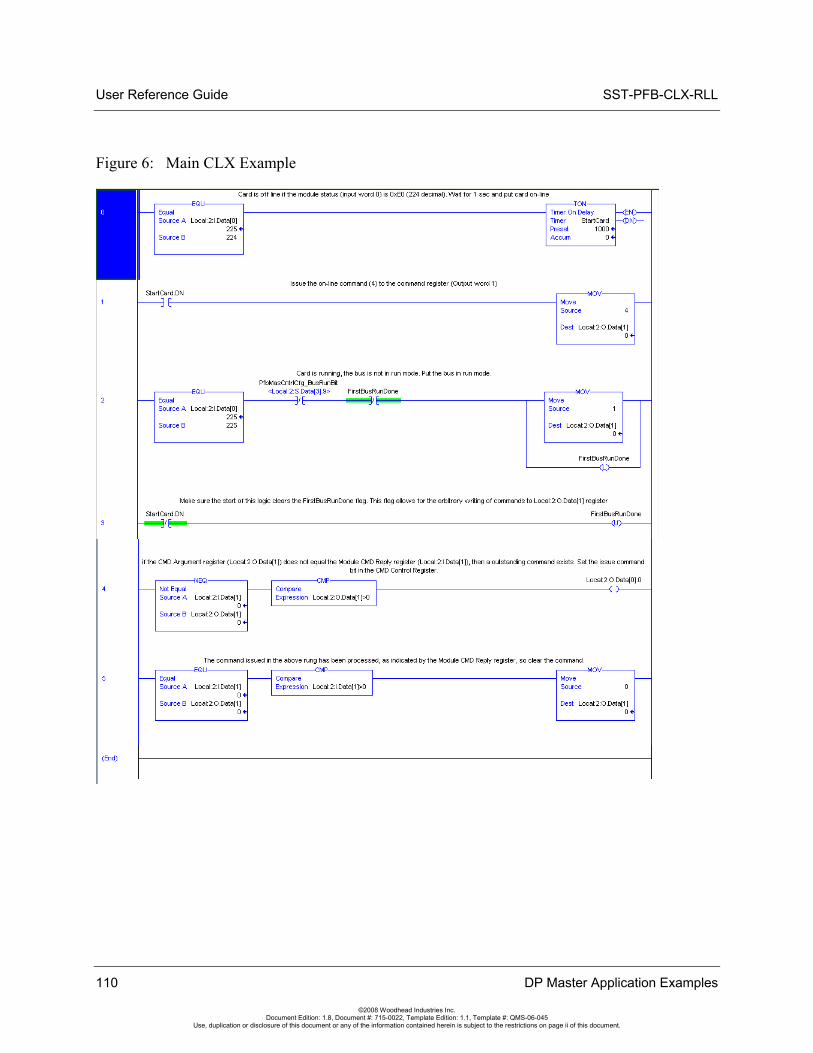
User Reference Guide SST-PFB-CLX-RLL
Figure 6: Main CLX Example
110 DP Master Application Examples
©2008 Woodhead Industries Inc. Document Edition: 1.8, Document #: 715-0022, Template Edition: 1.1, Template #: QMS-06-045
Use, duplication or disclosure of this document or any of the information contained herein is subject to the restrictions on page ii of this document.
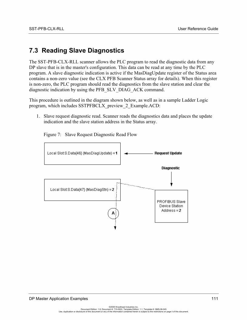
SST-PFB-CLX-RLL User Reference Guide
7.3 Reading Slave Diagnostics The SST-PFB-CLX-RLL scanner allows the PLC program to read the diagnostic data from any DP slave that is in the master's configuration. This data can be read at any time by the PLC program. A slave diagnostic indication is active if the MasDiagUpdate register of the Status area contains a non-zero value (see the CLX PFB Scanner Status array for details). When this register is non-zero, the PLC program should read the diagnostics from the slave station and clear the diagnostic indication by using the PFB_SLV_DIAG_ACK command.
This procedure is outlined in the diagram shown below, as well as in a sample Ladder Logic program, which includes SSTPFBCLX_preview_2_Example.ACD:
1. Slave request diagnostic read. Scanner reads the diagnostics data and places the update indication and the slave station address in the Status array.
Figure 7: Slave Request Diagnostic Read Flow
DP Master Application Examples 111
©2008 Woodhead Industries Inc. Document Edition: 1.8, Document #: 715-0022, Template Edition: 1.1, Template #: QMS-06-045
Use, duplication or disclosure of this document or any of the information contained herein is subject to the restrictions on page ii of this document.
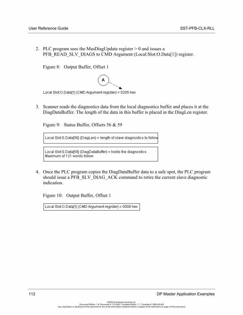
User Reference Guide SST-PFB-CLX-RLL
2. PLC program sees the MasDiagUpdate register > 0 and issues a PFB_READ_SLV_DIAGS to CMD Argument (Local:Slot:O.Data[1]) register.
Figure 8: Output Buffer, Offset 1
3. Scanner reads the diagnostics data from the local diagnostics buffer and places it at the DiagDataBuffer. The length of the data in this buffer is placed in the DiagLen register.
Figure 9: Status Buffer, Offsets 56 & 59
4. Once the PLC program copies the DiagDataBuffer data to a safe spot, the PLC program should issue a PFB_SLV_DIAG_ACK command to retire the current slave diagnostic indication.
Figure 10: Output Buffer, Offset 1
112 DP Master Application Examples
©2008 Woodhead Industries Inc. Document Edition: 1.8, Document #: 715-0022, Template Edition: 1.1, Template #: QMS-06-045
Use, duplication or disclosure of this document or any of the information contained herein is subject to the restrictions on page ii of this document.
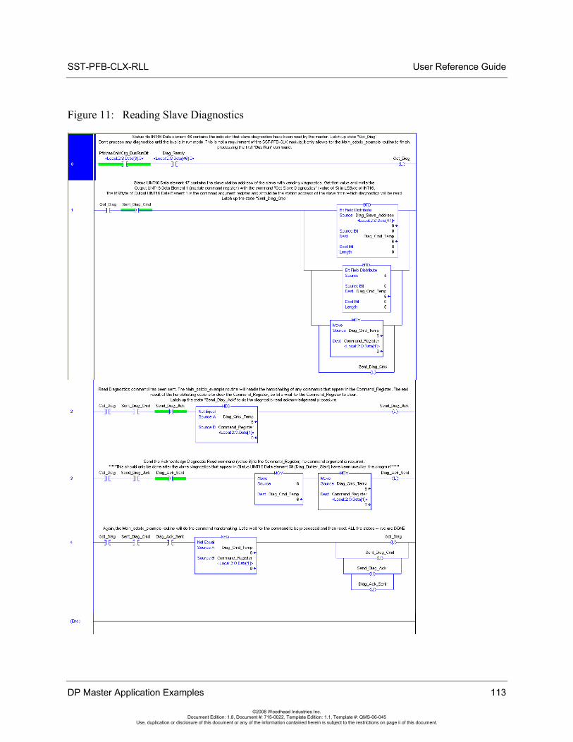
SST-PFB-CLX-RLL User Reference Guide
Figure 11: Reading Slave Diagnostics
DP Master Application Examples 113
©2008 Woodhead Industries Inc. Document Edition: 1.8, Document #: 715-0022, Template Edition: 1.1, Template #: QMS-06-045
Use, duplication or disclosure of this document or any of the information contained herein is subject to the restrictions on page ii of this document.
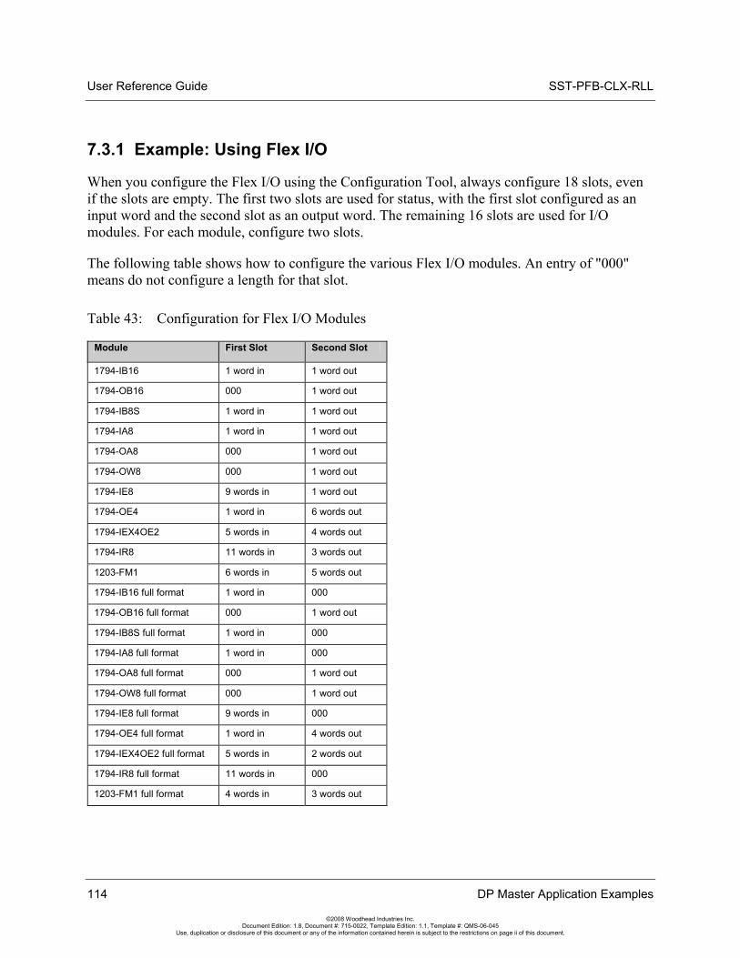
User Reference Guide SST-PFB-CLX-RLL
114 DP Master Application Examples
©2008 Woodhead Industries Inc. Document Edition: 1.8, Document #: 715-0022, Template Edition: 1.1, Template #: QMS-06-045
Use, duplication or disclosure of this document or any of the information contained herein is subject to the restrictions on page ii of this document.
7.3.1 Example: Using Flex I/O
When you configure the Flex I/O using the Configuration Tool, always configure 18 slots, even if the slots are empty. The first two slots are used for status, with the first slot configured as an input word and the second slot as an output word. The remaining 16 slots are used for I/O modules. For each module, configure two slots.
The following table shows how to configure the various Flex I/O modules. An entry of "000" means do not configure a length for that slot.
Table 43: Configuration for Flex I/O Modules
Module First Slot Second Slot
1794-IB16 1 word in 1 word out
1794-OB16 000 1 word out
1794-IB8S 1 word in 1 word out
1794-IA8 1 word in 1 word out
1794-OA8 000 1 word out
1794-OW8 000 1 word out
1794-IE8 9 words in 1 word out
1794-OE4 1 word in 6 words out
1794-IEX4OE2 5 words in 4 words out
1794-IR8 11 words in 3 words out
1203-FM1 6 words in 5 words out
1794-IB16 full format 1 word in 000
1794-OB16 full format 000 1 word out
1794-IB8S full format 1 word in 000
1794-IA8 full format 1 word in 000
1794-OA8 full format 000 1 word out
1794-OW8 full format 000 1 word out
1794-IE8 full format 9 words in 000
1794-OE4 full format 1 word in 4 words out
1794-IEX4OE2 full format 5 words in 2 words out
1794-IR8 full format 11 words in 000
1203-FM1 full format 4 words in 3 words out
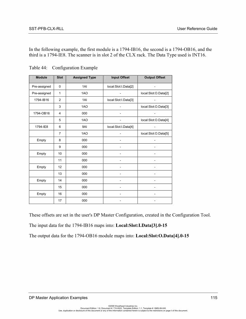
SST-PFB-CLX-RLL User Reference Guide
DP Master Application Examples 115
©2008 Woodhead Industries Inc. Document Edition: 1.8, Document #: 715-0022, Template Edition: 1.1, Template #: QMS-06-045
Use, duplication or disclosure of this document or any of the information contained herein is subject to the restrictions on page ii of this document.
In the following example, the first module is a 1794-IB16, the second is a 1794-OB16, and the third is a 1794-IE8. The scanner is in slot 2 of the CLX rack. The Data Type used is INT16.
Table 44: Configuration Example
Module Slot Assigned Type
Input Offset Output Offset
Pre-assigned 0 1AI local:Slot:I.Data[2] -
Pre-assigned 1 1AO - local:Slot:O.Data[2]
1794-IB16 2 1AI local:Slot:I.Data[3] -
3 1AO - local:Slot:O.Data[3]
1794-OB16 4 000 - -
5 1AO - local:Slot:O.Data[4]
1794-IE8 6 9AI local:Slot:I.Data[4] -
7 1AO - local:Slot:O.Data[5]
Empty 8 000 - -
9 000 - -
Empty 10 000 - -
11 000 - -
Empty 12 000 - -
13 000 - -
Empty 14 000 - -
15 000 - -
Empty 16 000 - -
17 000 - -
These offsets are set in the user's DP Master Configuration, created in the Configuration Tool.
The input data for the 1794-IB16 maps into: Local:Slot:I.Data[3].0-15
The output data for the 1794-OB16 module maps into: Local:Slot:O.Data[4].0-15

User Reference Guide SST-PFB-CLX-RLL
116 DP Master Application Examples
©2008 Woodhead Industries Inc. Document Edition: 1.8, Document #: 715-0022, Template Edition: 1.1, Template #: QMS-06-045
Use, duplication or disclosure of this document or any of the information contained herein is subject to the restrictions on page ii of this document.
SST-PFB-CLX-RLL User Reference Guide
Upgrading the Scanner Firmware 117
©2008 Woodhead Industries Inc. Document Edition: 1.8, Document #: 715-0022, Template Edition: 1.1, Template #: QMS-06-045
Use, duplication or disclosure of this document or any of the information contained herein is subject to the restrictions on page ii of this document.
8 Upgrading the Scanner Firmware
Chapter Sections:
• Upgrading the Scanner Firmware
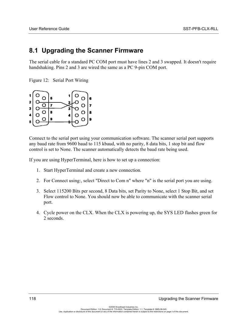
User Reference Guide SST-PFB-CLX-RLL
8.1 Upgrading the Scanner Firmware The serial cable for a standard PC COM port must have lines 2 and 3 swapped. It doesn't require handshaking. Pins 2 and 3 are wired the same as a PC 9-pin COM port.
Figure 12: Serial Port Wiring
Connect to the serial port using your communication software. The scanner serial port supports any baud rate from 9600 baud to 115 kbaud, with no parity, 8 data bits, 1 stop bit and flow control is set to None. The scanner automatically detects the baud rate being used.
If you are using HyperTerminal, here is how to set up a connection:
1. Start HyperTerminal and create a new connection.
2. For Connect using:, select "Direct to Com n" where "n" is the serial port you are using.
3. Select 115200 Bits per second, 8 Data bits, set Parity to None, select 1 Stop Bit, and set Flow control to None. You should now be able to communicate with the scanner serial port.
4. Cycle power on the CLX. When the CLX is powering up, the SYS LED flashes green for 2 seconds.
118 Upgrading the Scanner Firmware
©2008 Woodhead Industries Inc. Document Edition: 1.8, Document #: 715-0022, Template Edition: 1.1, Template #: QMS-06-045
Use, duplication or disclosure of this document or any of the information contained herein is subject to the restrictions on page ii of this document.
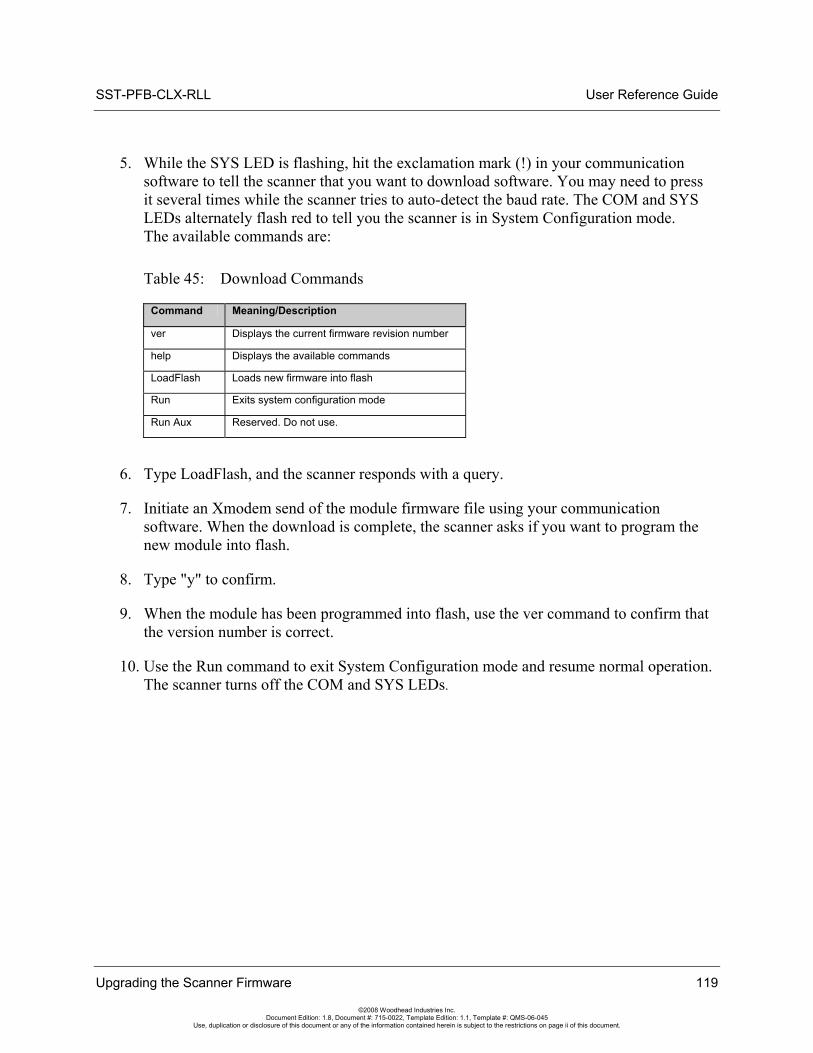
SST-PFB-CLX-RLL User Reference Guide
Upgrading the Scanner Firmware 119
©2008 Woodhead Industries Inc. Document Edition: 1.8, Document #: 715-0022, Template Edition: 1.1, Template #: QMS-06-045
Use, duplication or disclosure of this document or any of the information contained herein is subject to the restrictions on page ii of this document.
5. While the SYS LED is flashing, hit the exclamation mark (!) in your communication software to tell the scanner that you want to download software. You may need to press it several times while the scanner tries to auto-detect the baud rate. The COM and SYS LEDs alternately flash red to tell you the scanner is in System Configuration mode. The available commands are:
Table 45: Download Commands
Command Meaning/Description
ver Displays the current firmware revision number
help Displays the available commands
LoadFlash Loads new firmware into flash
Run Exits system configuration mode
Run Aux Reserved. Do not use.
6. Type LoadFlash, and the scanner responds with a query.
7. Initiate an Xmodem send of the module firmware file using your communication software. When the download is complete, the scanner asks if you want to program the new module into flash.
8. Type "y" to confirm.
9. When the module has been programmed into flash, use the ver command to confirm that the version number is correct.
10. Use the Run command to exit System Configuration mode and resume normal operation. The scanner turns off the COM and SYS LEDs.
User Reference Guide SST-PFB-CLX-RLL
120 Upgrading the Scanner Firmware
©2008 Woodhead Industries Inc. Document Edition: 1.8, Document #: 715-0022, Template Edition: 1.1, Template #: QMS-06-045
Use, duplication or disclosure of this document or any of the information contained herein is subject to the restrictions on page ii of this document.
SST-PFB-CLX-RLL User Reference Guide
Network Parameter Defaults 121
©2008 Woodhead Industries Inc. Document Edition: 1.8, Document #: 715-0022, Template Edition: 1.1, Template #: QMS-06-045
Use, duplication or disclosure of this document or any of the information contained herein is subject to the restrictions on page ii of this document.
9 Network Parameter Defaults
Chapter Sections:
• Network Parameter Default Values
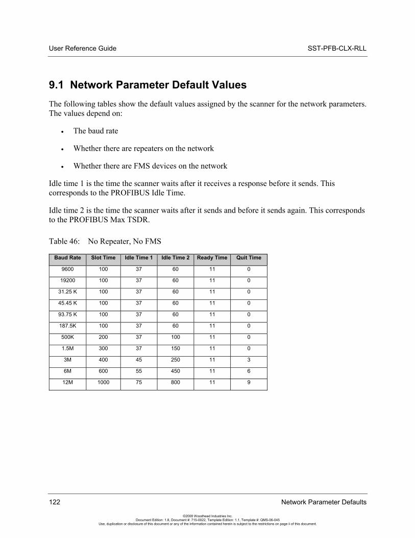
User Reference Guide SST-PFB-CLX-RLL
122 Network Parameter Defaults
©2008 Woodhead Industries Inc. Document Edition: 1.8, Document #: 715-0022, Template Edition: 1.1, Template #: QMS-06-045
Use, duplication or disclosure of this document or any of the information contained herein is subject to the restrictions on page ii of this document.
9.1 Network Parameter Default Values The following tables show the default values assigned by the scanner for the network parameters. The values depend on:
• The baud rate
• Whether there are repeaters on the network
• Whether there are FMS devices on the network
Idle time 1 is the time the scanner waits after it receives a response before it sends. This corresponds to the PROFIBUS Idle Time.
Idle time 2 is the time the scanner waits after it sends and before it sends again. This corresponds to the PROFIBUS Max TSDR.
Table 46: No Repeater, No FMS
Baud Rate Slot Time Idle Time 1 Idle Time 2 Ready Time Quit Time
9600 100 37 60 11 0
19200 100 37 60 11 0
31.25 K 100 37 60 11 0
45.45 K 100 37 60 11 0
93.75 K 100 37 60 11 0
187.5K 100 37 60 11 0
500K 200 37 100 11 0
1.5M 300 37 150 11 0
3M 400 45 250 11 3
6M 600 55 450 11 6
12M 1000 75 800 11 9
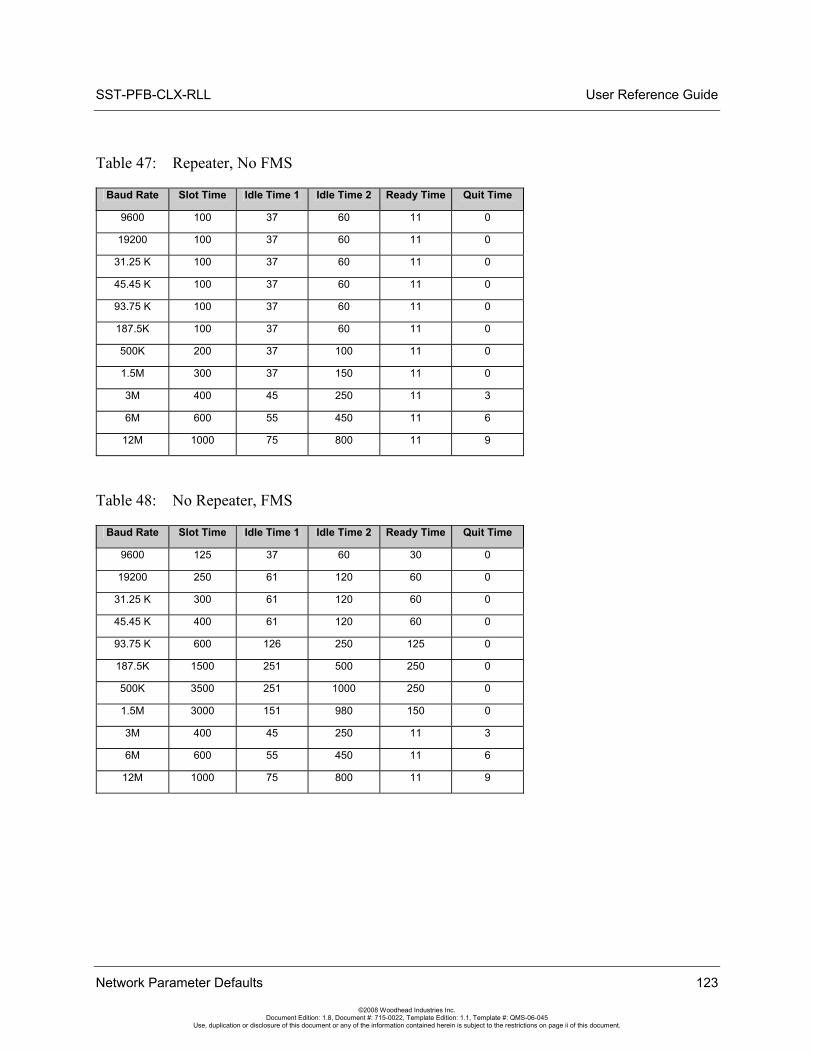
SST-PFB-CLX-RLL User Reference Guide
Network Parameter Defaults 123
©2008 Woodhead Industries Inc. Document Edition: 1.8, Document #: 715-0022, Template Edition: 1.1, Template #: QMS-06-045
Use, duplication or disclosure of this document or any of the information contained herein is subject to the restrictions on page ii of this document.
Table 47: Repeater, No FMS
Baud Rate Slot Time Idle Time 1 Idle Time 2 Ready Time Quit Time
9600 100 37 60 11 0
19200 100 37 60 11 0
31.25 K 100 37 60 11 0
45.45 K 100 37 60 11 0
93.75 K 100 37 60 11 0
187.5K 100 37 60 11 0
500K 200 37 100 11 0
1.5M 300 37 150 11 0
3M 400 45 250 11 3
6M 600 55 450 11 6
12M 1000 75 800 11 9
Table 48: No Repeater, FMS
Baud Rate Slot Time Idle Time 1 Idle Time 2 Ready Time Quit Time
9600 125 37 60 30 0
19200 250 61 120 60 0
31.25 K 300 61 120 60 0
45.45 K 400 61 120 60 0
93.75 K 600 126 250 125 0
187.5K 1500 251 500 250 0
500K 3500 251 1000 250 0
1.5M 3000 151 980 150 0
3M 400 45 250 11 3
6M 600 55 450 11 6
12M 1000 75 800 11 9
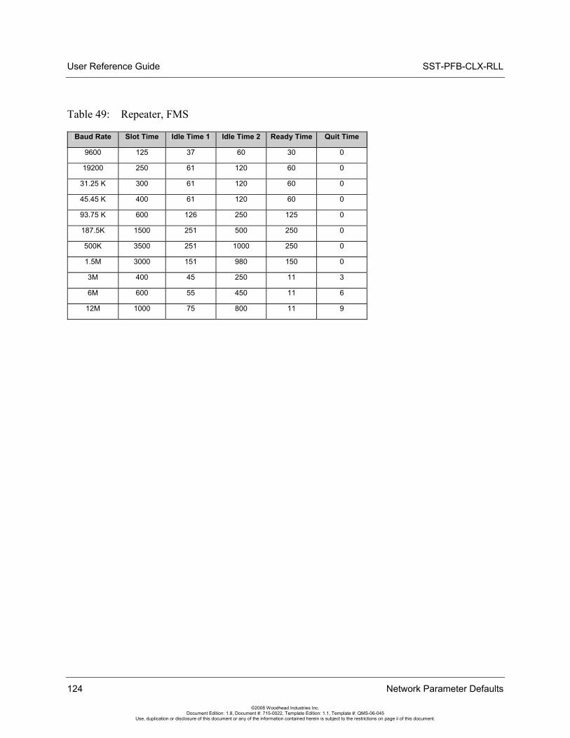
User Reference Guide SST-PFB-CLX-RLL
124 Network Parameter Defaults
©2008 Woodhead Industries Inc. Document Edition: 1.8, Document #: 715-0022, Template Edition: 1.1, Template #: QMS-06-045
Use, duplication or disclosure of this document or any of the information contained herein is subject to the restrictions on page ii of this document.
Table 49: Repeater, FMS
Baud Rate Slot Time Idle Time 1 Idle Time 2 Ready Time Quit Time
9600 125 37 60 30 0
19200 250 61 120 60 0
31.25 K 300 61 120 60 0
45.45 K 400 61 120 60 0
93.75 K 600 126 250 125 0
187.5K 1500 251 500 250 0
500K 3500 251 1000 250 0
1.5M 3000 151 980 150 0
3M 400 45 250 11 3
6M 600 55 450 11 6
12M 1000 75 800 11 9
SST-PFB-CLX-RLL User Reference Guide
Slave Functionality 125
©2008 Woodhead Industries Inc. Document Edition: 1.8, Document #: 715-0022, Template Edition: 1.1, Template #: QMS-06-045
Use, duplication or disclosure of this document or any of the information contained herein is subject to the restrictions on page ii of this document.
10 Slave Functionality
Chapter Sections:
• SST-PFB-CLX-RLL DP Slave Features
• Register Definitions and Layout
• Slave Configuration and Programming
User Reference Guide SST-PFB-CLX-RLL
126 Slave Functionality
©2008 Woodhead Industries Inc. Document Edition: 1.8, Document #: 715-0022, Template Edition: 1.1, Template #: QMS-06-045
Use, duplication or disclosure of this document or any of the information contained herein is subject to the restrictions on page ii of this document.
10.1 SST-PFB-CLX-RLL DP Slave Features The SST-PFB-CLX-RLL DP Slave has the following features:
• A maximum of 244 bytes input and 244 bytes output for slave functionality
• A maximum total input data size of 1984 bytes and output size of 1976 bytes combined, for DP master and slave
• Support for all standard PROFIBUS baud rates
• Slave configuration via the ControlLogix configuration file
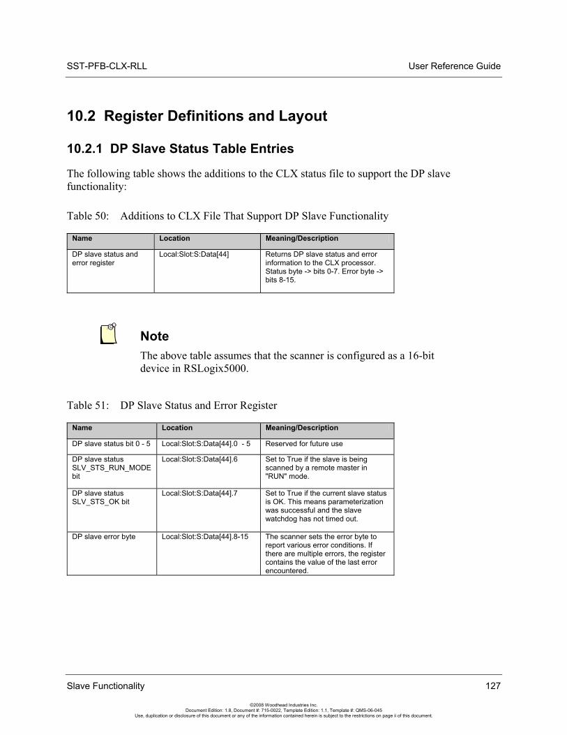
SST-PFB-CLX-RLL User Reference Guide
10.2 Register Definitions and Layout
10.2.1 DP Slave Status Table Entries
The following table shows the additions to the CLX status file to support the DP slave functionality:
Table 50: Additions to CLX File That Support DP Slave Functionality
Name Location Meaning/Description
DP slave status and error register
Local:Slot:S:Data[44] Returns DP slave status and error information to the CLX processor. Status byte -> bits 0-7. Error byte -> bits 8-15.
Note The above table assumes that the scanner is configured as a 16-bit device in RSLogix5000.
Table 51: DP Slave Status and Error Register
Name Location Meaning/Description
DP slave status bit 0 - 5 Local:Slot:S:Data[44].0 - 5 Reserved for future use
DP slave status SLV_STS_RUN_MODE bit
Local:Slot:S:Data[44].6 Set to True if the slave is being scanned by a remote master in "RUN" mode.
DP slave status SLV_STS_OK bit
Local:Slot:S:Data[44].7 Set to True if the current slave status is OK. This means parameterization was successful and the slave watchdog has not timed out.
DP slave error byte Local:Slot:S:Data[44].8-15 The scanner sets the error byte to report various error conditions. If there are multiple errors, the register contains the value of the last error encountered.
Slave Functionality 127
©2008 Woodhead Industries Inc. Document Edition: 1.8, Document #: 715-0022, Template Edition: 1.1, Template #: QMS-06-045
Use, duplication or disclosure of this document or any of the information contained herein is subject to the restrictions on page ii of this document.
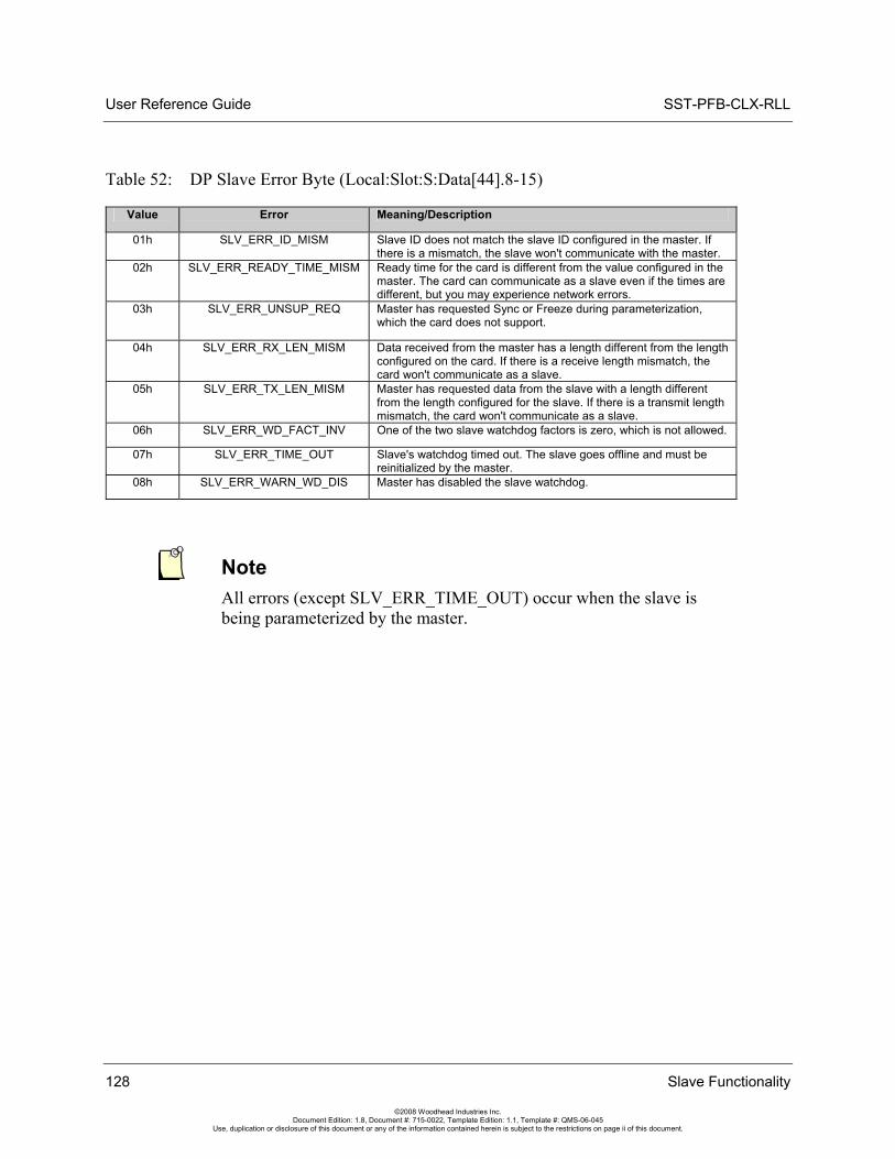
User Reference Guide SST-PFB-CLX-RLL
Table 52: DP Slave Error Byte (Local:Slot:S:Data[44].8-15)
Value Error Meaning/Description
01h SLV_ERR_ID_MISM Slave ID does not match the slave ID configured in the master. If there is a mismatch, the slave won't communicate with the master.
02h SLV_ERR_READY_TIME_MISM Ready time for the card is different from the value configured in the master. The card can communicate as a slave even if the times are different, but you may experience network errors.
03h SLV_ERR_UNSUP_REQ Master has requested Sync or Freeze during parameterization, which the card does not support.
04h SLV_ERR_RX_LEN_MISM Data received from the master has a length different from the length configured on the card. If there is a receive length mismatch, the card won't communicate as a slave.
05h SLV_ERR_TX_LEN_MISM Master has requested data from the slave with a length different from the length configured for the slave. If there is a transmit length mismatch, the card won't communicate as a slave.
06h SLV_ERR_WD_FACT_INV One of the two slave watchdog factors is zero, which is not allowed.
07h SLV_ERR_TIME_OUT Slave's watchdog timed out. The slave goes offline and must be reinitialized by the master.
08h SLV_ERR_WARN_WD_DIS Master has disabled the slave watchdog.
Note All errors (except SLV_ERR_TIME_OUT) occur when the slave is being parameterized by the master.
128 Slave Functionality
©2008 Woodhead Industries Inc. Document Edition: 1.8, Document #: 715-0022, Template Edition: 1.1, Template #: QMS-06-045
Use, duplication or disclosure of this document or any of the information contained herein is subject to the restrictions on page ii of this document.
SST-PFB-CLX-RLL User Reference Guide
10.2.2 I/O Table Additions/Modifications
If the slave is configured, the slave I/O is always mapped into the CLX I/O table after the master data. By default, the slave data will be mapped immediately following the master data; however, "hard addresses" can be specified in the CLX config file. This adds the ability to specify the starting slave data address in the I/O files. This can be used to leave a gap between master and slave data. This way, if the master network configuration changes, it does not affect the offsets of the slave data in the CLX I/O files. If the master is not configured, the default mapping of slave data is the beginning of the CLX I/O tables where the master data usually starts. Again, this default can be changed by assigning "hard addresses" in the CLX config file.
Received data is data received from the remote master. This data is mapped into the CLX input table. Transmit data is data that the scanner module sends to the remote master. This data is mapped into the CLX output table.
10.2.3 Config Table Additions
The CLX config table will be used to configure the slave functionality. The slave table entries follow the config area used by the master. This maintains backward compatibility in the config file.
The slave config file entries start at 10H (16D).
Note The CLX config file is always configured as byte locations. The CLX config file must be set to at least 24 bytes in size for Slave-only Mode. For Master and Slave mode, the minimum size is 26 bytes.
Slave Functionality 129
©2008 Woodhead Industries Inc. Document Edition: 1.8, Document #: 715-0022, Template Edition: 1.1, Template #: QMS-06-045
Use, duplication or disclosure of this document or any of the information contained herein is subject to the restrictions on page ii of this document.
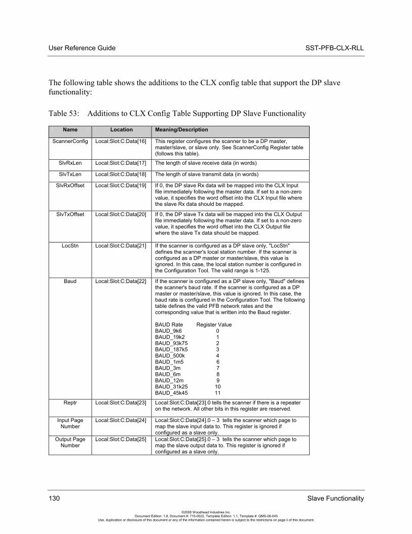
User Reference Guide SST-PFB-CLX-RLL
130 Slave Functionality
©2008 Woodhead Industries Inc. Document Edition: 1.8, Document #: 715-0022, Template Edition: 1.1, Template #: QMS-06-045
Use, duplication or disclosure of this document or any of the information contained herein is subject to the restrictions on page ii of this document.
The following table shows the additions to the CLX config table that support the DP slave functionality:
Table 53: Additions to CLX Config Table Supporting DP Slave Functionality
Name Location Meaning/Description
ScannerConfig Local:Slot:C:Data[16] This register configures the scanner to be a DP master, master/slave, or slave only. See ScannerConfig Register table (follows this table).
SlvRxLen Local:Slot:C:Data[17] The length of slave receive data (in words)
SlvTxLen Local:Slot:C:Data[18] The length of slave transmit data (in words)
SlvRxOffset Local:Slot:C:Data[19] If 0, the DP slave Rx data will be mapped into the CLX Input file immediately following the master data. If set to a non-zero value, it specifies the word offset into the CLX Input file where the slave Rx data should be mapped.
SlvTxOffset Local:Slot:C:Data[20] If 0, the DP slave Tx data will be mapped into the CLX Output file immediately following the master data. If set to a non-zero value, it specifies the word offset into the CLX Output file where the slave Tx data should be mapped.
LocStn Local:Slot:C:Data[21] If the scanner is configured as a DP slave only, "LocStn" defines the scanner's local station number. If the scanner is configured as a DP master or master/slave, this value is ignored. In this case, the local station number is configured in the Configuration Tool. The valid range is 1-125.
Baud Local:Slot:C:Data[22] If the scanner is configured as a DP slave only, "Baud" defines the scanner's baud rate. If the scanner is configured as a DP master or master/slave, this value is ignored. In this case, the baud rate is configured in the Configuration Tool. The following table defines the valid PFB network rates and the corresponding value that is written into the Baud register. BAUD Rate Register Value BAUD_9k6 0 BAUD_19k2 1 BAUD_93k75 2 BAUD_187k5 3 BAUD_500k 4 BAUD_1m5 6 BAUD_3m 7 BAUD_6m 8 BAUD_12m 9 BAUD_31k25 10 BAUD_45k45 11
Reptr Local:Slot:C:Data[23] Local:Slot:C:Data[23].0 tells the scanner if there is a repeater on the network. All other bits in this register are reserved.
Input Page Number
Local:Slot:C:Data[24] Local:Slot:C:Data[24].0 – 3 tells the scanner which page to map the slave input data to. This register is ignored if configured as a slave only.
Output Page Number
Local:Slot:C:Data[25] Local:Slot:C:Data[25].0 – 3 tells the scanner which page to map the slave output data to. This register is ignored if configured as a slave only.
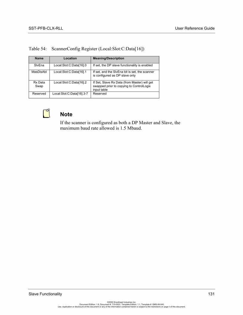
SST-PFB-CLX-RLL User Reference Guide
Table 54: ScannerConfig Register (Local:Slot:C:Data[16])
Name Location Meaning/Description
SlvEna Local:Slot:C:Data[16].0 If set, the DP slave functionality is enabled
MasDisAbl Local:Slot:C:Data[16].1 If set, and the SlvEna bit is set, the scanner is configured as DP slave only
Rx Data Swap
Local:Slot:C:Data[16].2 If Set, Slave Rx Data (from Master) will get swapped prior to copying to ControlLogix input table
Reserved Local:Slot:C:Data[16].3-7 Reserved
Note If the scanner is configured as both a DP Master and Slave, the maximum baud rate allowed is 1.5 Mbaud.
Slave Functionality 131
©2008 Woodhead Industries Inc. Document Edition: 1.8, Document #: 715-0022, Template Edition: 1.1, Template #: QMS-06-045
Use, duplication or disclosure of this document or any of the information contained herein is subject to the restrictions on page ii of this document.
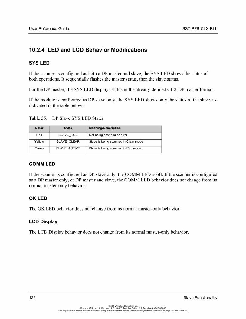
User Reference Guide SST-PFB-CLX-RLL
132 Slave Functionality
©2008 Woodhead Industries Inc. Document Edition: 1.8, Document #: 715-0022, Template Edition: 1.1, Template #: QMS-06-045
Use, duplication or disclosure of this document or any of the information contained herein is subject to the restrictions on page ii of this document.
10.2.4 LED and LCD Behavior Modifications
SYS LED
If the scanner is configured as both a DP master and slave, the SYS LED shows the status of both operations. It sequentially flashes the master status, then the slave status.
For the DP master, the SYS LED displays status in the already-defined CLX DP master format.
If the module is configured as DP slave only, the SYS LED shows only the status of the slave, as indicated in the table below:
Table 55: DP Slave SYS LED States
Color State Meaning/Description
Red SLAVE_IDLE Not being scanned or error
Yellow SLAVE_CLEAR Slave is being scanned in Clear mode
Green SLAVE_ACTIVE Slave is being scanned in Run mode
COMM LED
If the scanner is configured as DP slave only, the COMM LED is off. If the scanner is configured as a DP master only, or DP master and slave, the COMM LED behavior does not change from its normal master-only behavior.
OK LED
The OK LED behavior does not change from its normal master-only behavior.
LCD Display
The LCD Display behavior does not change from its normal master-only behavior.
SST-PFB-CLX-RLL User Reference Guide
10.3 Slave Configuration and Programming
Note If you’re defining your own offsets for CLX slave data in the ControlLogix configuration file, they must be greater than the highest data offset of the slave in the master configuration. So, for example, if the highest input offset the CLX master uses for a slave is 20 with 1 word input, then the slave RX offset could be set to 21 or greater.
If you’re using firmware version 5.24 or greater, CLX slave data can be mapped to a page other than 0. The Configuration Tool will not know which offsets you mapped your slave data to, so if you are mapping Master data to the same page, do not overlap the addresses assigned by the Tool.
The CLX slave accepts the ControlLogix configuration only once after power-up. This means that if after power-up you change the ControlLogix configuration file settings (Station number, baud rate and so on) in your RSLogix 5000 Program and download it to the ControlLogix PLC, the new setting will not take effect.
There are three ways to have the new configuration settings accepted:
1. Cycle power on the module before new configuration settings are accepted.
2. Follow these steps:
a. Put the PLC into PROG mode b. Connect serially to the module via the Configuration Tool c. Issue the Offline command d. Edit the ControlLogix file e. Download the PLC program f. Put the PLC into RUN mode
3. Follow these steps:
a. Put the PLC into PROG mode b. Connect serially to the module via the Configuration Tool c. Issue the Offline command d. Edit the ontrolLogix file while Online with PLC via RSLogix e. Disable and enable connection by using the inhibit function in RSLogix 5000
under I/O configuration > Module Properties > Connection tab
Slave Functionality 133
©2008 Woodhead Industries Inc. Document Edition: 1.8, Document #: 715-0022, Template Edition: 1.1, Template #: QMS-06-045
Use, duplication or disclosure of this document or any of the information contained herein is subject to the restrictions on page ii of this document.
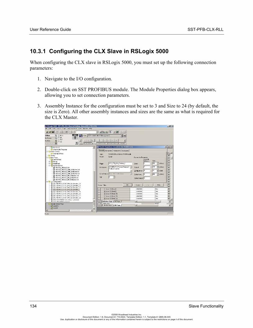
User Reference Guide SST-PFB-CLX-RLL
10.3.1 Configuring the CLX Slave in RSLogix 5000
When configuring the CLX slave in RSLogix 5000, you must set up the following connection parameters:
1. Navigate to the I/O configuration.
2. Double-click on SST PROFIBUS module. The Module Properties dialog box appears, allowing you to set connection parameters.
3. Assembly Instance for the configuration must be set to 3 and Size to 24 (by default, the size is Zero). All other assembly instances and sizes are the same as what is required for the CLX Master.
134 Slave Functionality
©2008 Woodhead Industries Inc. Document Edition: 1.8, Document #: 715-0022, Template Edition: 1.1, Template #: QMS-06-045
Use, duplication or disclosure of this document or any of the information contained herein is subject to the restrictions on page ii of this document.
SST-PFB-CLX-RLL User Reference Guide
DPV1 Master Functionality 135
©2008 Woodhead Industries Inc. Document Edition: 1.8, Document #: 715-0022, Template Edition: 1.1, Template #: QMS-06-045
Use, duplication or disclosure of this document or any of the information contained herein is subject to the restrictions on page ii of this document.
11 DPV1 Master Functionality
Chapter Sections:
• General Features
• DPV1-Supported Functions
• DPV1 Command Description
• Creating a CIP Generic Message for Transmitting a DPV1 Command
• DPV1 Sample Code
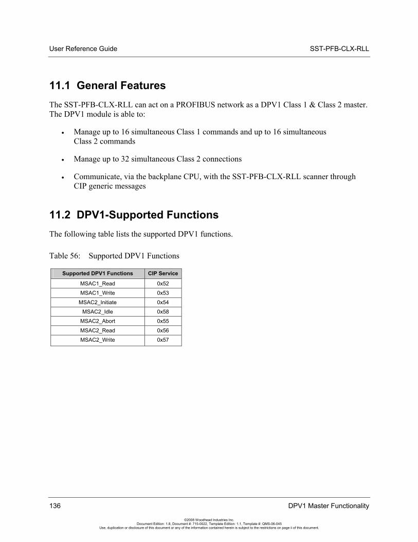
User Reference Guide SST-PFB-CLX-RLL
136 DPV1 Master Functionality
©2008 Woodhead Industries Inc. Document Edition: 1.8, Document #: 715-0022, Template Edition: 1.1, Template #: QMS-06-045
Use, duplication or disclosure of this document or any of the information contained herein is subject to the restrictions on page ii of this document.
11.1 General Features The SST-PFB-CLX-RLL can act on a PROFIBUS network as a DPV1 Class 1 & Class 2 master. The DPV1 module is able to:
• Manage up to 16 simultaneous Class 1 commands and up to 16 simultaneous Class 2 commands
• Manage up to 32 simultaneous Class 2 connections
• Communicate, via the backplane CPU, with the SST-PFB-CLX-RLL scanner through CIP generic messages
11.2 DPV1-Supported Functions The following table lists the supported DPV1 functions.
Table 56: Supported DPV1 Functions
Supported DPV1 Functions CIP Service
MSAC1_Read 0x52
MSAC1_Write 0x53
MSAC2_Initiate 0x54
MSAC2_Idle 0x58
MSAC2_Abort 0x55
MSAC2_Read 0x56
MSAC2_Write 0x57
SST-PFB-CLX-RLL User Reference Guide
11.3 DPV1 Command Description
11.3.1 Overview
The backplane CPU can send DPV1 commands to slaves through the scanner. To do this, the backplane CPU issues CIP generic messages to the SST-PFB-CLX-RLL. Object 0x101, Instance 1 is used.
To process a DPV1 command, the scanner should be initialized by the backplane CPU with the DPV1_INIT Command (it must be in offline configured mode to accept this command). DPV1 Class 1 commands can be sent after initialization when the scanner is online.
To set up a DPV1 Class 2 communication, the backplane CPU should send an Initiate command. The scanner maintains Class 2 communication automatically, until a network error occurs. The backplane CPU should close the class communication via an Abort command. The CPU can restart the Class2 communication with an Initiate command if needed.
When DPV1 communication is no longer needed, the backplane CPU should stop the DPV1 module via a DPV1 Close command.
Note The following arrays assume an alignment of 1 byte; make sure that the ladder program's set parameters at the correct offsets.
DPV1 Master Functionality 137
©2008 Woodhead Industries Inc. Document Edition: 1.8, Document #: 715-0022, Template Edition: 1.1, Template #: QMS-06-045
Use, duplication or disclosure of this document or any of the information contained herein is subject to the restrictions on page ii of this document.
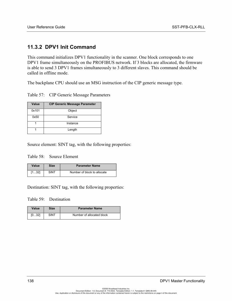
User Reference Guide SST-PFB-CLX-RLL
138 DPV1 Master Functionality
©2008 Woodhead Industries Inc. Document Edition: 1.8, Document #: 715-0022, Template Edition: 1.1, Template #: QMS-06-045
Use, duplication or disclosure of this document or any of the information contained herein is subject to the restrictions on page ii of this document.
11.3.2 DPV1 Init Command
This command initializes DPV1 functionality in the scanner. One block corresponds to one DPV1 frame simultaneously on the PROFIBUS network. If 3 blocks are allocated, the firmware is able to send 3 DPV1 frames simultaneously to 3 different slaves. This command should be called in offline mode.
The backplane CPU should use an MSG instruction of the CIP generic message type.
Table 57: CIP Generic Message Parameters
Value CIP Generic Message Parameter
0x101 Object
0x50 Service
1 Instance
1 Length
Source element: SINT tag, with the following properties:
Table 58: Source Element
Value Size Parameter Name
[1...32] SINT Number of block to allocate
Destination: SINT tag, with the following properties:
Table 59: Destination
Value Size Parameter Name
[0...32] SINT Number of allocated block
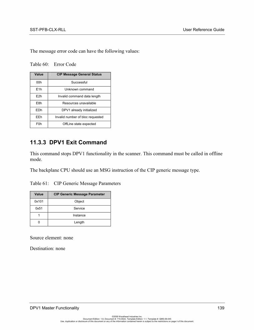
SST-PFB-CLX-RLL User Reference Guide
DPV1 Master Functionality 139
©2008 Woodhead Industries Inc. Document Edition: 1.8, Document #: 715-0022, Template Edition: 1.1, Template #: QMS-06-045
Use, duplication or disclosure of this document or any of the information contained herein is subject to the restrictions on page ii of this document.
The message error code can have the following values:
Table 60: Error Code
Value CIP Message General Status
00h Successful
E1h Unknown command
E2h Invalid command data length
E8h Resources unavailable
EDh DPV1 already initialized
EEh Invalid number of bloc requested
F0h OffLine state expected
11.3.3 DPV1 Exit Command
This command stops DPV1 functionality in the scanner. This command must be called in offline mode.
The backplane CPU should use an MSG instruction of the CIP generic message type.
Table 61: CIP Generic Message Parameters
Value CIP Generic Message Parameter
0x101 Object
0x51 Service
1 Instance
0 Length
Source element: none
Destination: none
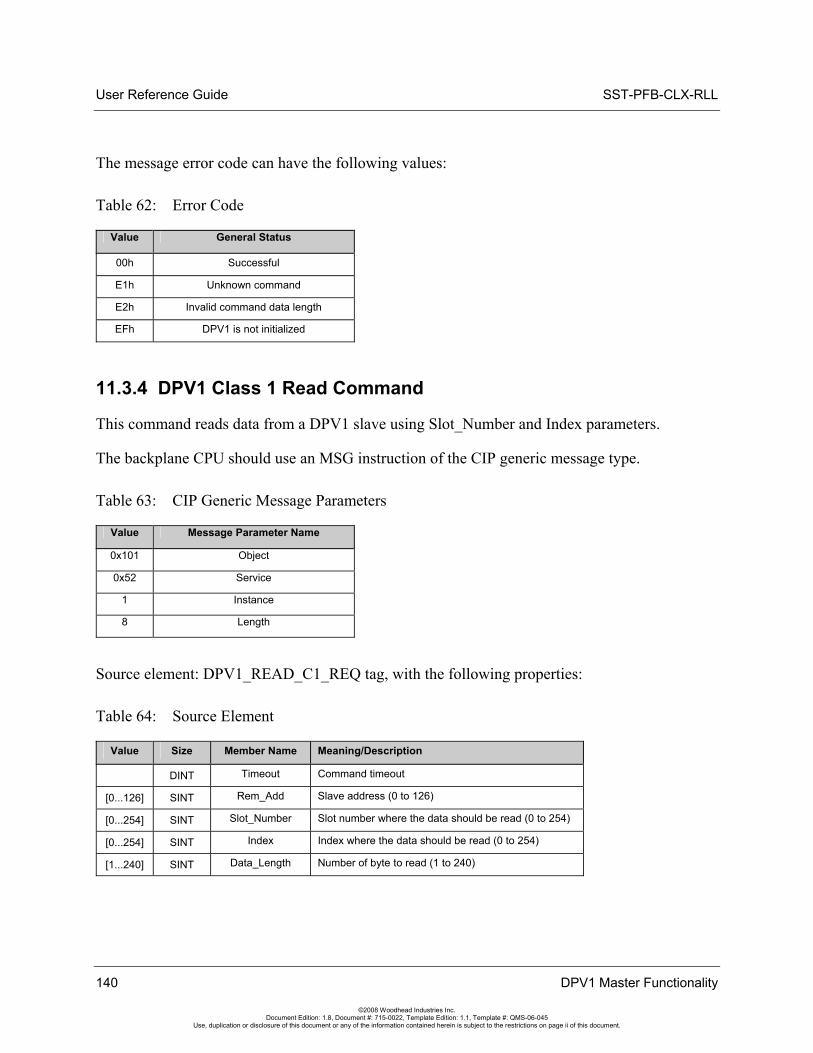
User Reference Guide SST-PFB-CLX-RLL
140 DPV1 Master Functionality
©2008 Woodhead Industries Inc. Document Edition: 1.8, Document #: 715-0022, Template Edition: 1.1, Template #: QMS-06-045
Use, duplication or disclosure of this document or any of the information contained herein is subject to the restrictions on page ii of this document.
The message error code can have the following values:
Table 62: Error Code
Value General Status
00h Successful
E1h Unknown command
E2h Invalid command data length
EFh DPV1 is not initialized
11.3.4 DPV1 Class 1 Read Command
This command reads data from a DPV1 slave using Slot_Number and Index parameters.
The backplane CPU should use an MSG instruction of the CIP generic message type.
Table 63: CIP Generic Message Parameters
Value Message Parameter Name
0x101 Object
0x52 Service
1 Instance
8 Length
Source element: DPV1_READ_C1_REQ tag, with the following properties:
Table 64: Source Element
Value Size Member Name Meaning/Description
DINT Timeout Command timeout
[0...126] SINT Rem_Add Slave address (0 to 126)
[0...254] SINT Slot_Number Slot number where the data should be read (0 to 254)
[0...254] SINT Index Index where the data should be read (0 to 254)
[1...240] SINT Data_Length Number of byte to read (1 to 240)
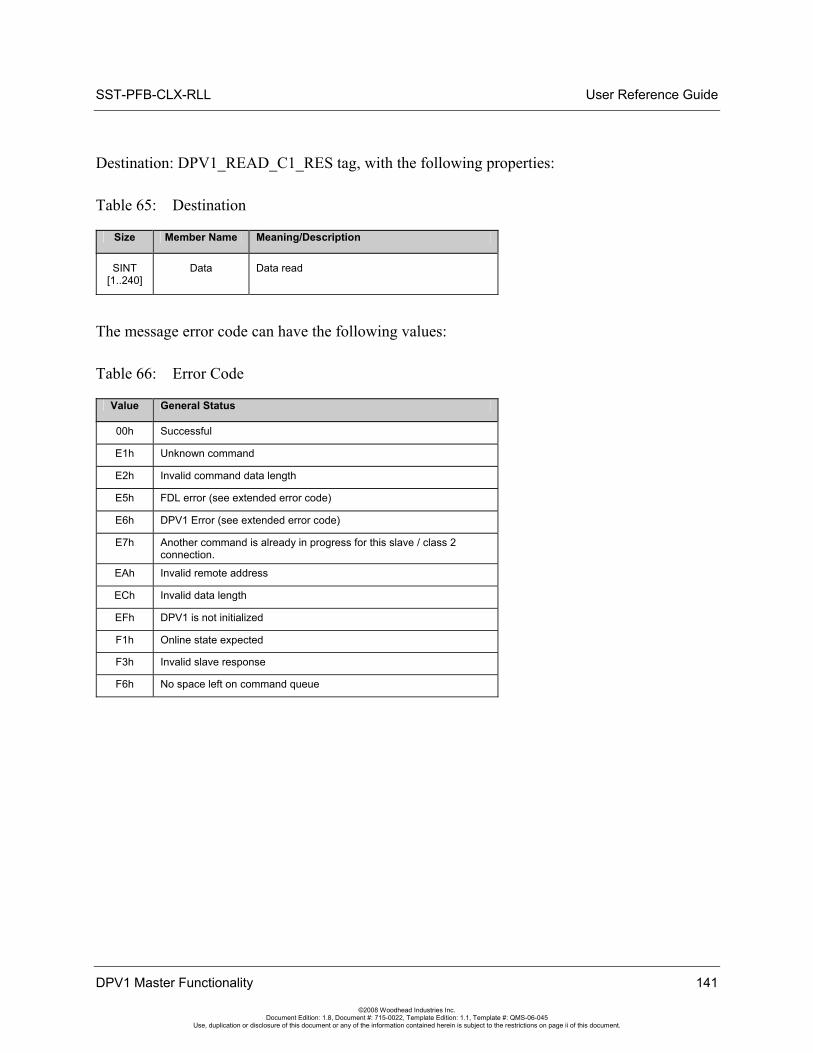
SST-PFB-CLX-RLL User Reference Guide
DPV1 Master Functionality 141
©2008 Woodhead Industries Inc. Document Edition: 1.8, Document #: 715-0022, Template Edition: 1.1, Template #: QMS-06-045
Use, duplication or disclosure of this document or any of the information contained herein is subject to the restrictions on page ii of this document.
Destination: DPV1_READ_C1_RES tag, with the following properties:
Table 65: Destination
Size Member Name Meaning/Description
SINT [1..240]
Data Data read
The message error code can have the following values:
Table 66: Error Code
Value General Status
00h Successful
E1h Unknown command
E2h Invalid command data length
E5h FDL error (see extended error code)
E6h DPV1 Error (see extended error code)
E7h Another command is already in progress for this slave / class 2 connection.
EAh Invalid remote address
ECh Invalid data length
EFh DPV1 is not initialized
F1h Online state expected
F3h Invalid slave response
F6h No space left on command queue
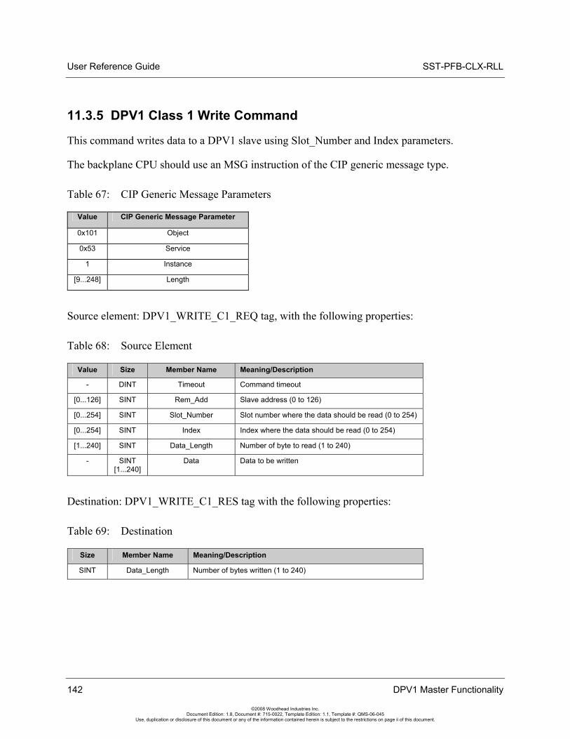
User Reference Guide SST-PFB-CLX-RLL
142 DPV1 Master Functionality
©2008 Woodhead Industries Inc. Document Edition: 1.8, Document #: 715-0022, Template Edition: 1.1, Template #: QMS-06-045
Use, duplication or disclosure of this document or any of the information contained herein is subject to the restrictions on page ii of this document.
11.3.5 DPV1 Class 1 Write Command
This command writes data to a DPV1 slave using Slot_Number and Index parameters.
The backplane CPU should use an MSG instruction of the CIP generic message type.
Table 67: CIP Generic Message Parameters
Value CIP Generic Message Parameter
0x101 Object
0x53 Service
1 Instance
[9...248] Length
Source element: DPV1_WRITE_C1_REQ tag, with the following properties:
Table 68: Source Element
Value Size Member Name Meaning/Description
- DINT Timeout Command timeout
[0...126] SINT Rem_Add Slave address (0 to 126)
[0...254] SINT Slot_Number Slot number where the data should be read (0 to 254)
[0...254] SINT Index Index where the data should be read (0 to 254)
[1...240] SINT Data_Length Number of byte to read (1 to 240)
- SINT [1...240]
Data Data to be written
Destination: DPV1_WRITE_C1_RES tag with the following properties:
Table 69: Destination
Size Member Name Meaning/Description
SINT Data_Length Number of bytes written (1 to 240)
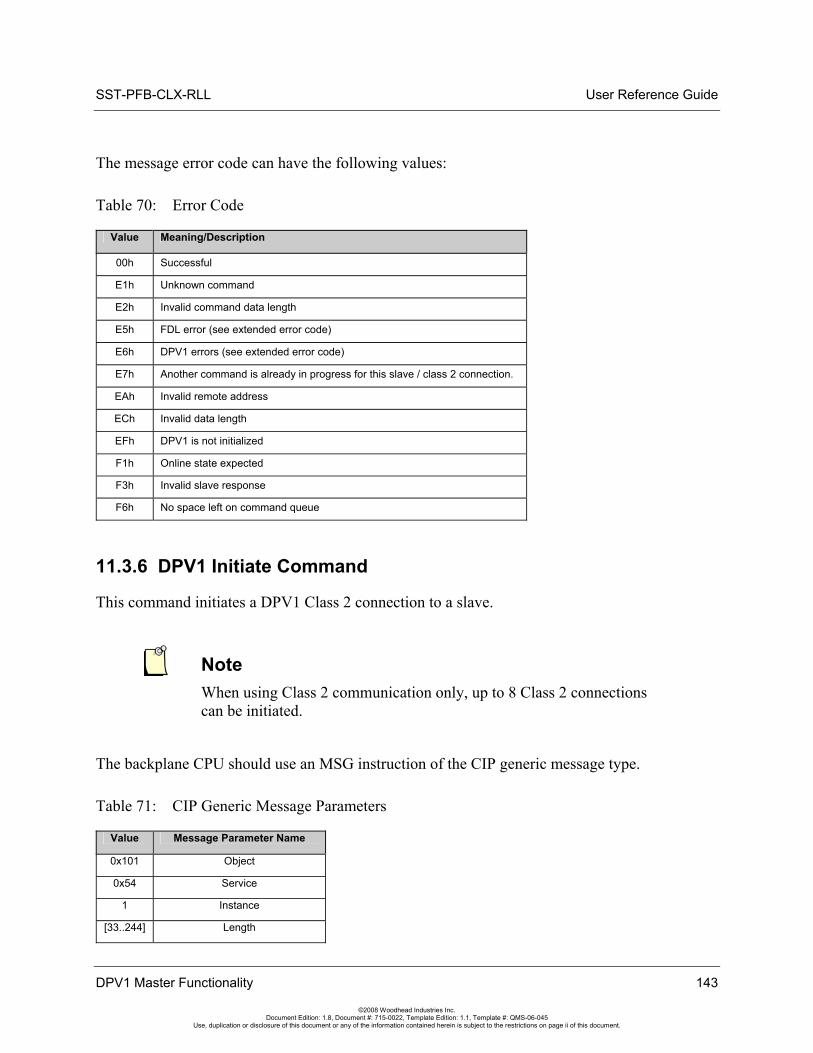
SST-PFB-CLX-RLL User Reference Guide
The message error code can have the following values:
Table 70: Error Code
Value Meaning/Description
00h Successful
E1h Unknown command
E2h Invalid command data length
E5h FDL error (see extended error code)
E6h DPV1 errors (see extended error code)
E7h Another command is already in progress for this slave / class 2 connection.
EAh Invalid remote address
ECh Invalid data length
EFh DPV1 is not initialized
F1h Online state expected
F3h Invalid slave response
F6h No space left on command queue
11.3.6 DPV1 Initiate Command
This command initiates a DPV1 Class 2 connection to a slave.
Note When using Class 2 communication only, up to 8 Class 2 connections can be initiated.
The backplane CPU should use an MSG instruction of the CIP generic message type.
Table 71: CIP Generic Message Parameters
Value Message Parameter Name
0x101 Object
0x54 Service
1 Instance
[33..244] Length
DPV1 Master Functionality 143
©2008 Woodhead Industries Inc. Document Edition: 1.8, Document #: 715-0022, Template Edition: 1.1, Template #: QMS-06-045
Use, duplication or disclosure of this document or any of the information contained herein is subject to the restrictions on page ii of this document.
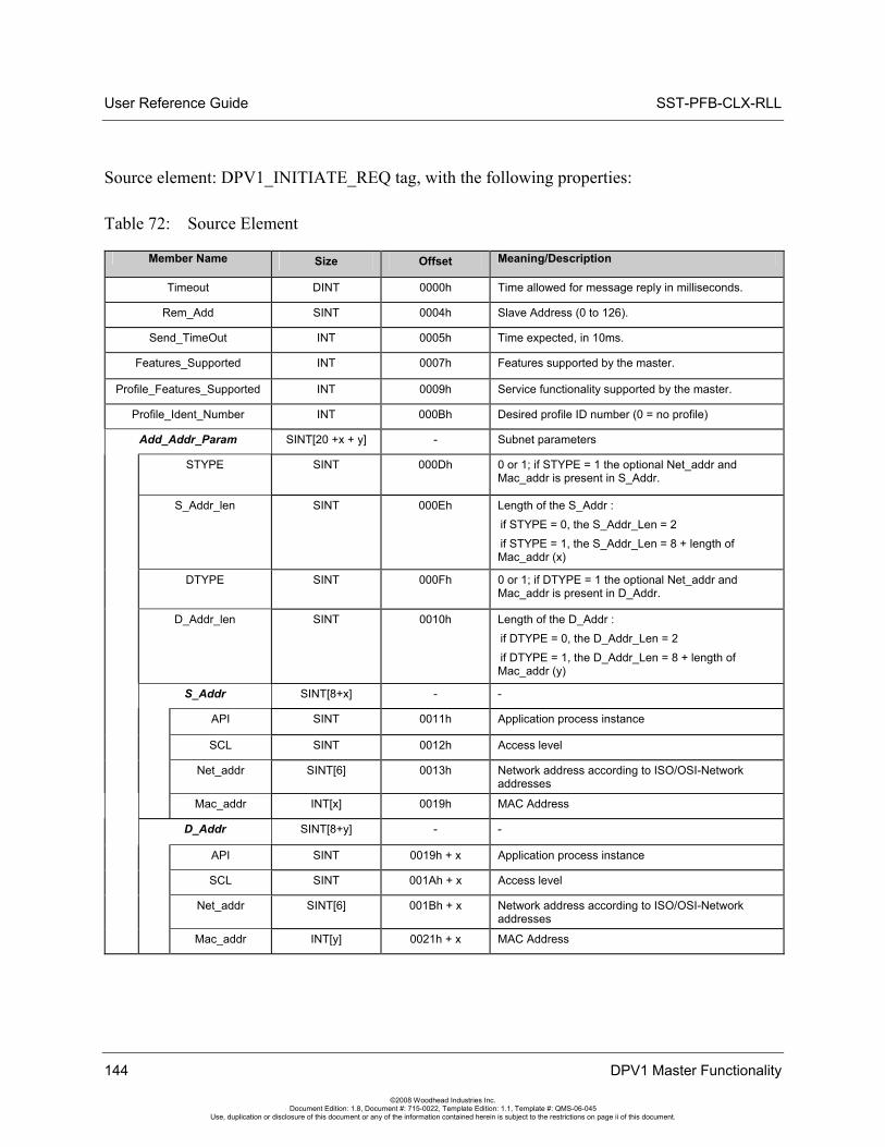
User Reference Guide SST-PFB-CLX-RLL
144 DPV1 Master Functionality
©2008 Woodhead Industries Inc. Document Edition: 1.8, Document #: 715-0022, Template Edition: 1.1, Template #: QMS-06-045
Use, duplication or disclosure of this document or any of the information contained herein is subject to the restrictions on page ii of this document.
Source element: DPV1_INITIATE_REQ tag, with the following properties:
Table 72: Source Element
Member Name Size Offset Meaning/Description
Timeout DINT 0000h Time allowed for message reply in milliseconds.
Rem_Add SINT 0004h Slave Address (0 to 126).
Send_TimeOut INT 0005h Time expected, in 10ms.
Features_Supported INT 0007h Features supported by the master.
Profile_Features_Supported INT 0009h Service functionality supported by the master.
Profile_Ident_Number INT 000Bh Desired profile ID number (0 = no profile)
Add_Addr_Param SINT[20 +x + y] - Subnet parameters
STYPE SINT 000Dh 0 or 1; if STYPE = 1 the optional Net_addr and Mac_addr is present in S_Addr.
S_Addr_len SINT 000Eh Length of the S_Addr : if STYPE = 0, the S_Addr_Len = 2 if STYPE = 1, the S_Addr_Len = 8 + length of Mac_addr (x)
DTYPE SINT 000Fh 0 or 1; if DTYPE = 1 the optional Net_addr and Mac_addr is present in D_Addr.
D_Addr_len SINT 0010h Length of the D_Addr : if DTYPE = 0, the D_Addr_Len = 2 if DTYPE = 1, the D_Addr_Len = 8 + length of Mac_addr (y)
S_Addr SINT[8+x] - -
API SINT 0011h Application process instance
SCL SINT 0012h Access level
Net_addr SINT[6] 0013h Network address according to ISO/OSI-Network addresses
Mac_addr INT[x] 0019h MAC Address
D_Addr SINT[8+y] - -
API SINT 0019h + x Application process instance
SCL SINT 001Ah + x Access level
Net_addr SINT[6] 001Bh + x Network address according to ISO/OSI-Network addresses
Mac_addr INT[y] 0021h + x MAC Address
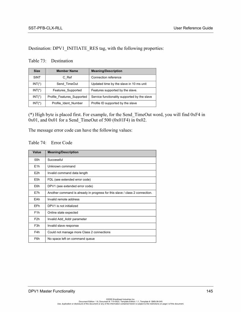
SST-PFB-CLX-RLL User Reference Guide
DPV1 Master Functionality 145
©2008 Woodhead Industries Inc. Document Edition: 1.8, Document #: 715-0022, Template Edition: 1.1, Template #: QMS-06-045
Use, duplication or disclosure of this document or any of the information contained herein is subject to the restrictions on page ii of this document.
Destination: DPV1_INITIATE_RES tag, with the following properties:
Table 73: Destination
Size Member Name Meaning/Description
SINT C_Ref Connection reference
INT(*) Send_TimeOut Updated time by the slave in 10 ms unit
INT(*) Features_Supported Features supported by the slave.
INT(*) Profile_Features_Supported Service functionality supported by the slave
INT(*) Profile_Ident_Number Profile ID supported by the slave
(*) High byte is placed first. For example, for the Send_TimeOut word, you will find 0xF4 in 0x01, and 0x01 for a Send_TimeOut of 500 (0x01F4) in 0x02.
The message error code can have the following values:
Table 74: Error Code
Value Meaning/Description
00h Successful
E1h Unknown command
E2h Invalid command data length
E5h FDL (see extended error code)
E6h DPV1 (see extended error code)
E7h Another command is already in progress for this slave / class 2 connection.
EAh Invalid remote address
EFh DPV1 is not initialized
F1h Online state expected
F2h Invalid Add_Addr parameter
F3h Invalid slave response
F4h Could not manage more Class 2 connections
F6h No space left on command queue
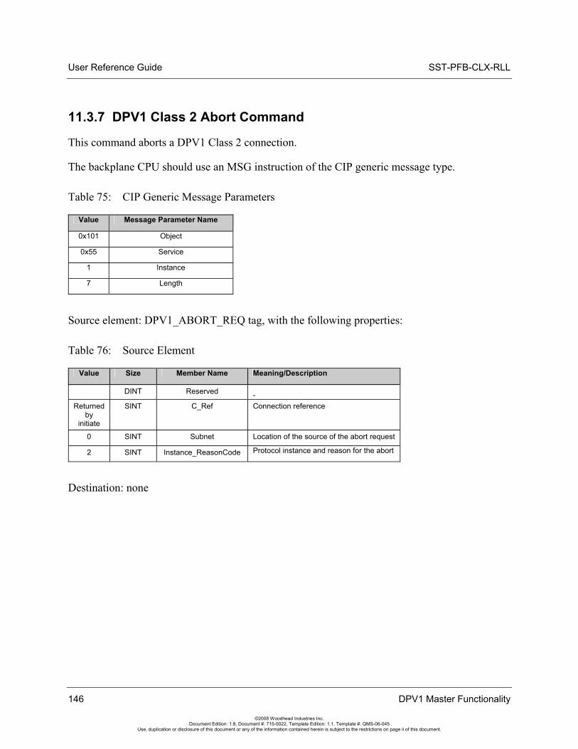
User Reference Guide SST-PFB-CLX-RLL
146 DPV1 Master Functionality
©2008 Woodhead Industries Inc. Document Edition: 1.8, Document #: 715-0022, Template Edition: 1.1, Template #: QMS-06-045
Use, duplication or disclosure of this document or any of the information contained herein is subject to the restrictions on page ii of this document.
11.3.7 DPV1 Class 2 Abort Command
This command aborts a DPV1 Class 2 connection.
The backplane CPU should use an MSG instruction of the CIP generic message type.
Table 75: CIP Generic Message Parameters
Value Message Parameter Name
0x101 Object
0x55 Service
1 Instance
7 Length
Source element: DPV1_ABORT_REQ tag, with the following properties:
Table 76: Source Element
Value Size Member Name Meaning/Description
DINT Reserved -Returned
by initiate
SINT C_Ref Connection reference
0 SINT Subnet Location of the source of the abort request
2 SINT Instance_ReasonCode Protocol instance and reason for the abort
Destination: none
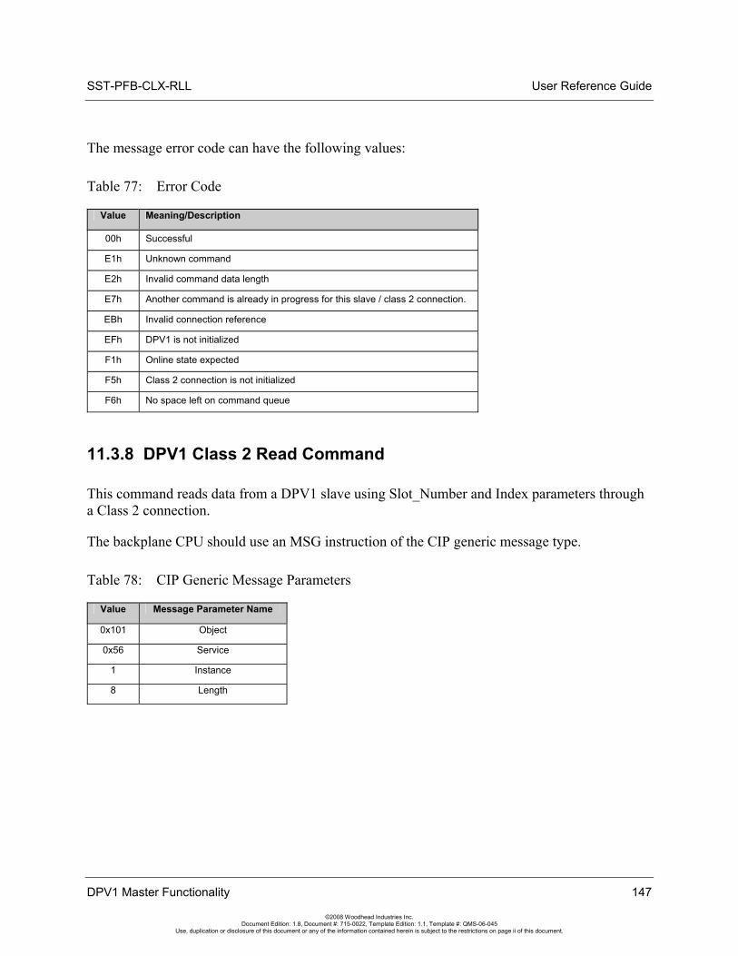
SST-PFB-CLX-RLL User Reference Guide
DPV1 Master Functionality 147
©2008 Woodhead Industries Inc. Document Edition: 1.8, Document #: 715-0022, Template Edition: 1.1, Template #: QMS-06-045
Use, duplication or disclosure of this document or any of the information contained herein is subject to the restrictions on page ii of this document.
The message error code can have the following values:
Table 77: Error Code
Value Meaning/Description
00h Successful
E1h Unknown command
E2h Invalid command data length
E7h Another command is already in progress for this slave / class 2 connection.
EBh Invalid connection reference
EFh DPV1 is not initialized
F1h Online state expected
F5h Class 2 connection is not initialized
F6h No space left on command queue
11.3.8 DPV1 Class 2 Read Command
This command reads data from a DPV1 slave using Slot_Number and Index parameters through a Class 2 connection.
The backplane CPU should use an MSG instruction of the CIP generic message type.
Table 78: CIP Generic Message Parameters
Value Message Parameter Name
0x101 Object
0x56 Service
1 Instance
8 Length
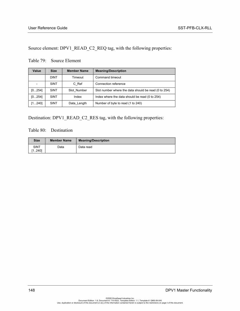
User Reference Guide SST-PFB-CLX-RLL
148 DPV1 Master Functionality
©2008 Woodhead Industries Inc. Document Edition: 1.8, Document #: 715-0022, Template Edition: 1.1, Template #: QMS-06-045
Use, duplication or disclosure of this document or any of the information contained herein is subject to the restrictions on page ii of this document.
Source element: DPV1_READ_C2_REQ tag, with the following properties:
Table 79: Source Element
Value Size Member Name Meaning/Description
DINT Timeout Command timeout
- SINT C_Ref Connection reference
[0...254] SINT Slot_Number Slot number where the data should be read (0 to 254)
[0...254] SINT Index Index where the data should be read (0 to 254)
[1...240] SINT Data_Length Number of byte to read (1 to 240)
Destination: DPV1_READ_C2_RES tag, with the following properties:
Table 80: Destination
Size Member Name Meaning/Description
SINT [1..240]
Data Data read
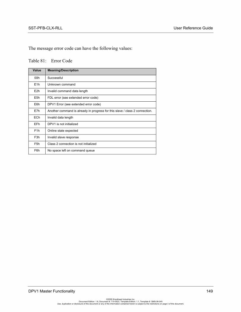
SST-PFB-CLX-RLL User Reference Guide
DPV1 Master Functionality 149
©2008 Woodhead Industries Inc. Document Edition: 1.8, Document #: 715-0022, Template Edition: 1.1, Template #: QMS-06-045
Use, duplication or disclosure of this document or any of the information contained herein is subject to the restrictions on page ii of this document.
The message error code can have the following values:
Table 81: Error Code
Value Meaning/Description
00h Successful
E1h Unknown command
E2h Invalid command data length
E5h FDL error (see extended error code)
E6h DPV1 Error (see extended error code)
E7h Another command is already in progress for this slave / class 2 connection.
ECh Invalid data length
EFh DPV1 is not initialized
F1h Online state expected
F3h Invalid slave response
F5h Class 2 connection is not initialized
F6h No space left on command queue
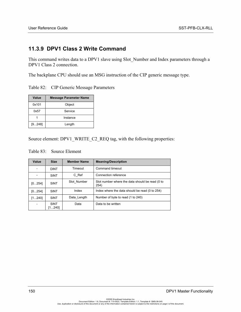
User Reference Guide SST-PFB-CLX-RLL
150 DPV1 Master Functionality
©2008 Woodhead Industries Inc. Document Edition: 1.8, Document #: 715-0022, Template Edition: 1.1, Template #: QMS-06-045
Use, duplication or disclosure of this document or any of the information contained herein is subject to the restrictions on page ii of this document.
11.3.9 DPV1 Class 2 Write Command
This command writes data to a DPV1 slave using Slot_Number and Index parameters through a DPV1 Class 2 connection.
The backplane CPU should use an MSG instruction of the CIP generic message type.
Table 82: CIP Generic Message Parameters
Value Message Parameter Name
0x101 Object
0x57 Service
1 Instance
[9...248] Length
Source element: DPV1_WRITE_C2_REQ tag, with the following properties:
Table 83: Source Element
Value Size Member Name Meaning/Description
- DINT Timeout Command timeout
- SINT C_Ref Connection reference
[0...254] SINT Slot_Number Slot number where the data should be read (0 to 254)
[0...254] SINT Index Index where the data should be read (0 to 254)
[1...240] SINT Data_Length Number of byte to read (1 to 240)
- SINT [1...240]
Data Data to be written
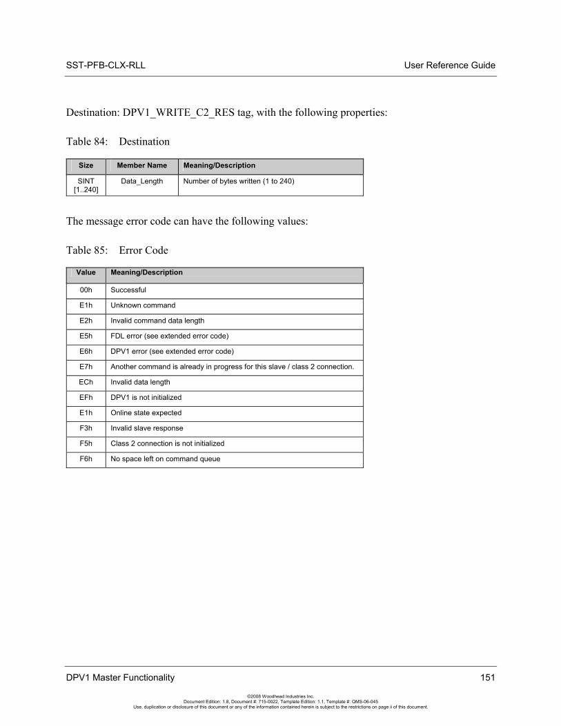
SST-PFB-CLX-RLL User Reference Guide
DPV1 Master Functionality 151
©2008 Woodhead Industries Inc. Document Edition: 1.8, Document #: 715-0022, Template Edition: 1.1, Template #: QMS-06-045
Use, duplication or disclosure of this document or any of the information contained herein is subject to the restrictions on page ii of this document.
Destination: DPV1_WRITE_C2_RES tag, with the following properties:
Table 84: Destination
Size Member Name Meaning/Description
SINT [1..240]
Data_Length Number of bytes written (1 to 240)
The message error code can have the following values:
Table 85: Error Code
Value Meaning/Description
00h Successful
E1h Unknown command
E2h Invalid command data length
E5h FDL error (see extended error code)
E6h DPV1 error (see extended error code)
E7h Another command is already in progress for this slave / class 2 connection.
ECh Invalid data length
EFh DPV1 is not initialized
E1h Online state expected
F3h Invalid slave response
F5h Class 2 connection is not initialized
F6h No space left on command queue
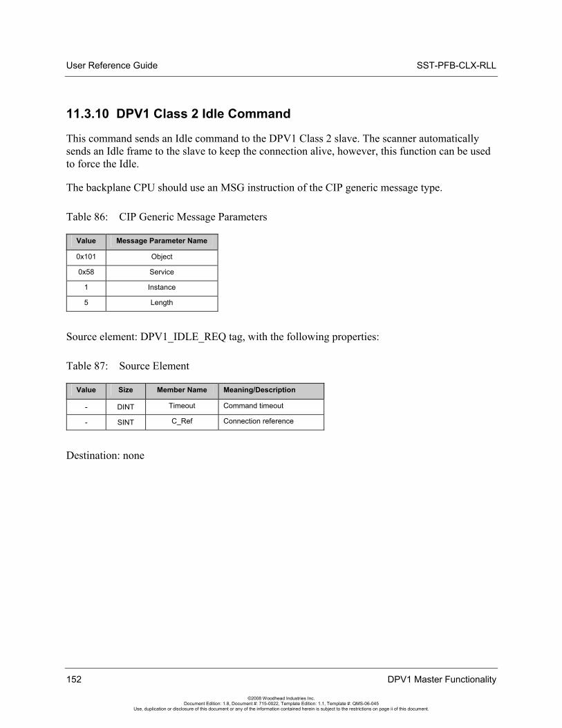
User Reference Guide SST-PFB-CLX-RLL
152 DPV1 Master Functionality
©2008 Woodhead Industries Inc. Document Edition: 1.8, Document #: 715-0022, Template Edition: 1.1, Template #: QMS-06-045
Use, duplication or disclosure of this document or any of the information contained herein is subject to the restrictions on page ii of this document.
11.3.10 DPV1 Class 2 Idle Command
This command sends an Idle command to the DPV1 Class 2 slave. The scanner automatically sends an Idle frame to the slave to keep the connection alive, however, this function can be used to force the Idle.
The backplane CPU should use an MSG instruction of the CIP generic message type.
Table 86: CIP Generic Message Parameters
Value Message Parameter Name
0x101 Object
0x58 Service
1 Instance
5 Length
Source element: DPV1_IDLE_REQ tag, with the following properties:
Table 87: Source Element
Value Size Member Name Meaning/Description
- DINT Timeout Command timeout
- SINT C_Ref Connection reference
Destination: none
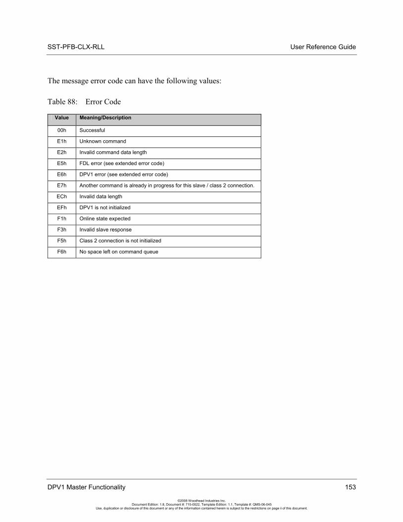
SST-PFB-CLX-RLL User Reference Guide
DPV1 Master Functionality 153
©2008 Woodhead Industries Inc. Document Edition: 1.8, Document #: 715-0022, Template Edition: 1.1, Template #: QMS-06-045
Use, duplication or disclosure of this document or any of the information contained herein is subject to the restrictions on page ii of this document.
The message error code can have the following values:
Table 88: Error Code
Value Meaning/Description
00h Successful
E1h Unknown command
E2h Invalid command data length
E5h FDL error (see extended error code)
E6h DPV1 error (see extended error code)
E7h Another command is already in progress for this slave / class 2 connection.
ECh Invalid data length
EFh DPV1 is not initialized
F1h Online state expected
F3h Invalid slave response
F5h Class 2 connection is not initialized
F6h No space left on command queue
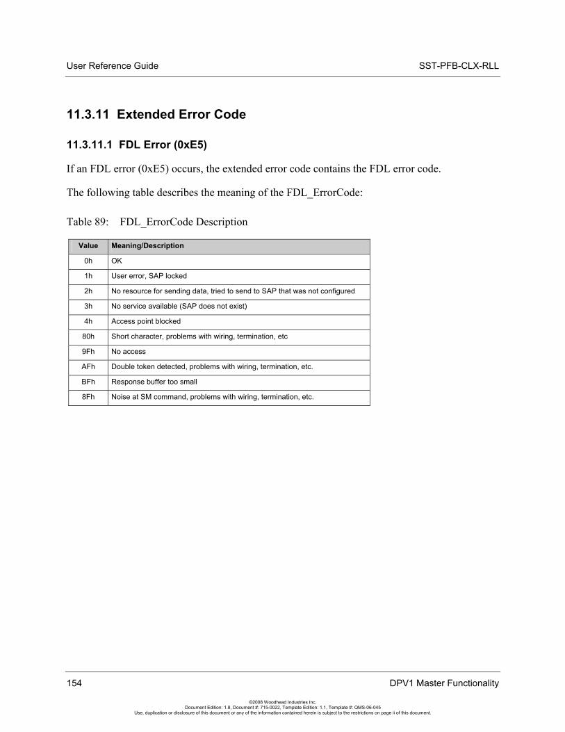
User Reference Guide SST-PFB-CLX-RLL
154 DPV1 Master Functionality
©2008 Woodhead Industries Inc. Document Edition: 1.8, Document #: 715-0022, Template Edition: 1.1, Template #: QMS-06-045
Use, duplication or disclosure of this document or any of the information contained herein is subject to the restrictions on page ii of this document.
11.3.11 Extended Error Code
11.3.11.1 FDL Error (0xE5)
If an FDL error (0xE5) occurs, the extended error code contains the FDL error code.
The following table describes the meaning of the FDL_ErrorCode:
Table 89: FDL_ErrorCode Description
Value Meaning/Description
0h OK
1h User error, SAP locked
2h No resource for sending data, tried to send to SAP that was not configured
3h No service available (SAP does not exist)
4h Access point blocked
80h Short character, problems with wiring, termination, etc
9Fh No access
AFh Double token detected, problems with wiring, termination, etc.
BFh Response buffer too small
8Fh Noise at SM command, problems with wiring, termination, etc.
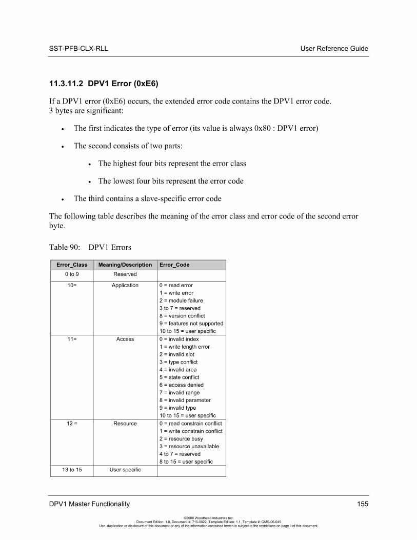
SST-PFB-CLX-RLL User Reference Guide
DPV1 Master Functionality 155
©2008 Woodhead Industries Inc. Document Edition: 1.8, Document #: 715-0022, Template Edition: 1.1, Template #: QMS-06-045
Use, duplication or disclosure of this document or any of the information contained herein is subject to the restrictions on page ii of this document.
11.3.11.2 DPV1 Error (0xE6)
If a DPV1 error (0xE6) occurs, the extended error code contains the DPV1 error code. 3 bytes are significant:
• The first indicates the type of error (its value is always 0x80 : DPV1 error)
• The second consists of two parts:
• The highest four bits represent the error class
• The lowest four bits represent the error code
• The third contains a slave-specific error code
The following table describes the meaning of the error class and error code of the second error byte.
Table 90: DPV1 Errors
Error_Class Meaning/Description Error_Code 0 to 9 Reserved
10= Application 0 = read error 1 = write error 2 = module failure 3 to 7 = reserved 8 = version conflict 9 = features not supported10 to 15 = user specific
11= Access 0 = invalid index 1 = write length error 2 = invalid slot 3 = type conflict 4 = invalid area 5 = state conflict 6 = access denied 7 = invalid range 8 = invalid parameter 9 = invalid type 10 to 15 = user specific
12 = Resource 0 = read constrain conflict 1 = write constrain conflict 2 = resource busy 3 = resource unavailable 4 to 7 = reserved 8 to 15 = user specific
13 to 15 User specific
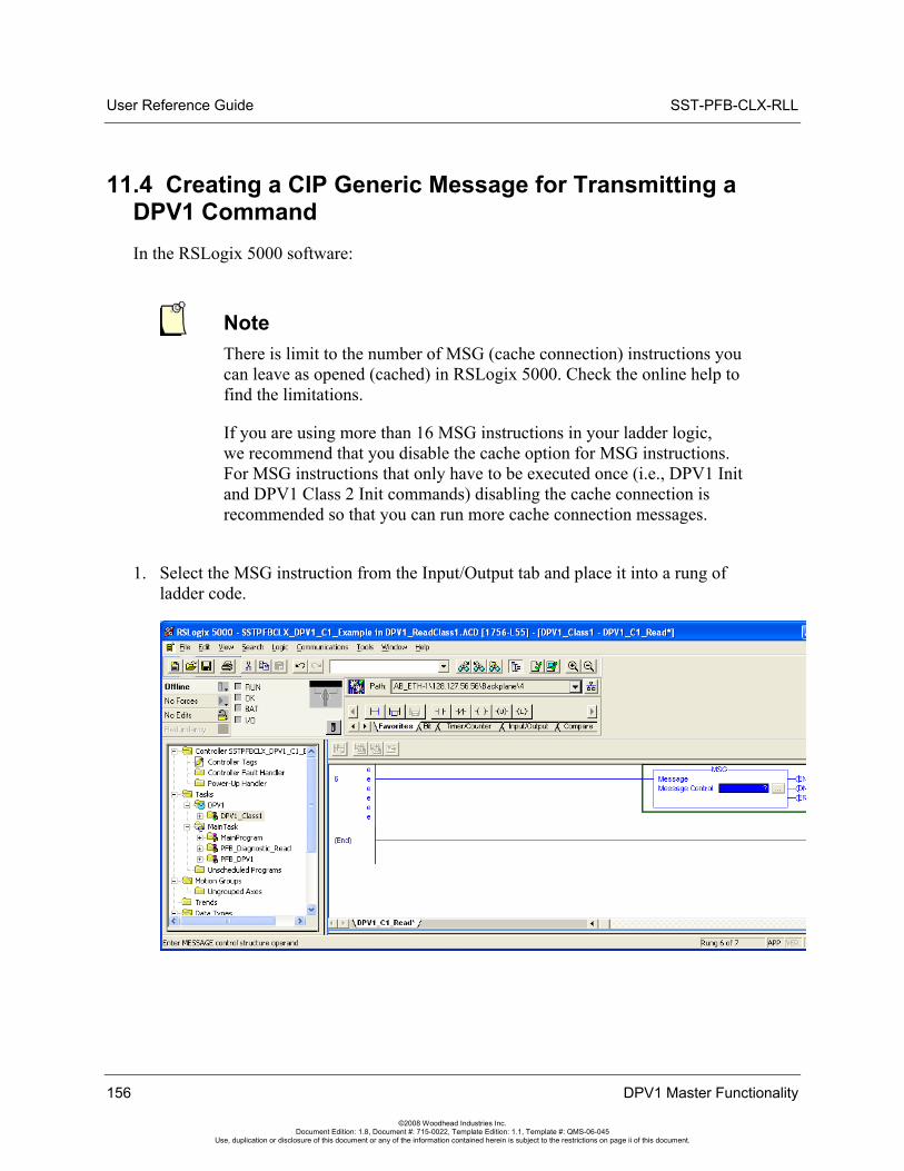
User Reference Guide SST-PFB-CLX-RLL
11.4 Creating a CIP Generic Message for Transmitting a DPV1 Command In the RSLogix 5000 software:
Note There is limit to the number of MSG (cache connection) instructions you can leave as opened (cached) in RSLogix 5000. Check the online help to find the limitations.
If you are using more than 16 MSG instructions in your ladder logic, we recommend that you disable the cache option for MSG instructions. For MSG instructions that only have to be executed once (i.e., DPV1 Init and DPV1 Class 2 Init commands) disabling the cache connection is recommended so that you can run more cache connection messages.
1. Select the MSG instruction from the Input/Output tab and place it into a rung of ladder code.
156 DPV1 Master Functionality
©2008 Woodhead Industries Inc. Document Edition: 1.8, Document #: 715-0022, Template Edition: 1.1, Template #: QMS-06-045
Use, duplication or disclosure of this document or any of the information contained herein is subject to the restrictions on page ii of this document.
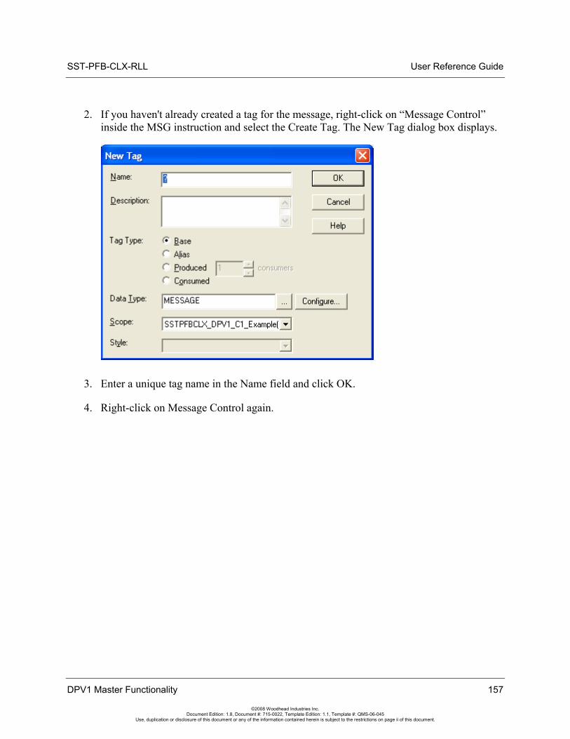
SST-PFB-CLX-RLL User Reference Guide
2. If you haven't already created a tag for the message, right-click on “Message Control” inside the MSG instruction and select the Create Tag. The New Tag dialog box displays.
3. Enter a unique tag name in the Name field and click OK.
4. Right-click on Message Control again.
DPV1 Master Functionality 157
©2008 Woodhead Industries Inc. Document Edition: 1.8, Document #: 715-0022, Template Edition: 1.1, Template #: QMS-06-045
Use, duplication or disclosure of this document or any of the information contained herein is subject to the restrictions on page ii of this document.
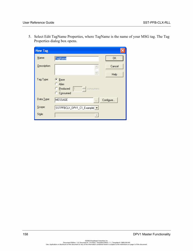
User Reference Guide SST-PFB-CLX-RLL
5. Select Edit TagName Properties, where TagName is the name of your MSG tag. The Tag Properties dialog box opens.
158 DPV1 Master Functionality
©2008 Woodhead Industries Inc. Document Edition: 1.8, Document #: 715-0022, Template Edition: 1.1, Template #: QMS-06-045
Use, duplication or disclosure of this document or any of the information contained herein is subject to the restrictions on page ii of this document.
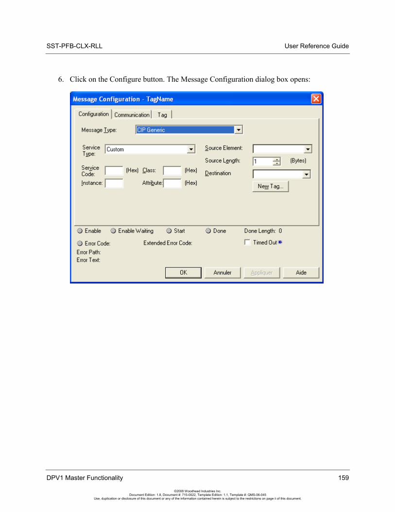
SST-PFB-CLX-RLL User Reference Guide
6. Click on the Configure button. The Message Configuration dialog box opens:
DPV1 Master Functionality 159
©2008 Woodhead Industries Inc. Document Edition: 1.8, Document #: 715-0022, Template Edition: 1.1, Template #: QMS-06-045
Use, duplication or disclosure of this document or any of the information contained herein is subject to the restrictions on page ii of this document.
User Reference Guide SST-PFB-CLX-RLL
160 DPV1 Master Functionality
©2008 Woodhead Industries Inc. Document Edition: 1.8, Document #: 715-0022, Template Edition: 1.1, Template #: QMS-06-045
Use, duplication or disclosure of this document or any of the information contained herein is subject to the restrictions on page ii of this document.
7. Under the Configuration tab, enter the following information:
Message Type: CIP Generic
Service Code: Your desired DPV1 command code
Class: Set to 101h
Instance: Set to 1
Attribute: Leave this field empty
Source Element: Select the variable source you created to hold the DPV1 request
Source Length: Select the number of bytes to transfer from the variable source
Destination: Select the destination variable you created to hold the DPV1 response
8. Under the Communication tab, set the scanner path to where you want to send the message.
9. Click OK to return to the Tag Properties dialog box.
10. Click OK again to close the dialog box.
11. If you are disabling the cache connection, go to Controller tags > Message Tag and set your Message tagname: EN_CC to 0.
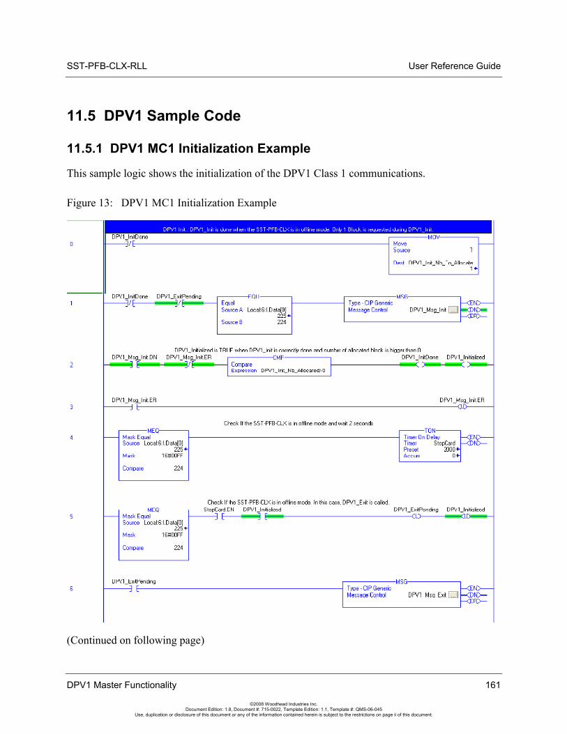
SST-PFB-CLX-RLL User Reference Guide
11.5 DPV1 Sample Code
11.5.1 DPV1 MC1 Initialization Example
This sample logic shows the initialization of the DPV1 Class 1 communications.
Figure 13: DPV1 MC1 Initialization Example
(Continued on following page)
DPV1 Master Functionality 161
©2008 Woodhead Industries Inc. Document Edition: 1.8, Document #: 715-0022, Template Edition: 1.1, Template #: QMS-06-045
Use, duplication or disclosure of this document or any of the information contained herein is subject to the restrictions on page ii of this document.
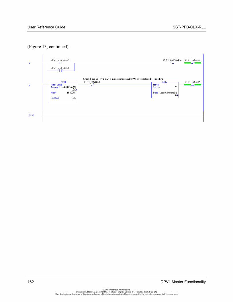
User Reference Guide SST-PFB-CLX-RLL
(Figure 13, continued).
162 DPV1 Master Functionality
©2008 Woodhead Industries Inc. Document Edition: 1.8, Document #: 715-0022, Template Edition: 1.1, Template #: QMS-06-045
Use, duplication or disclosure of this document or any of the information contained herein is subject to the restrictions on page ii of this document.
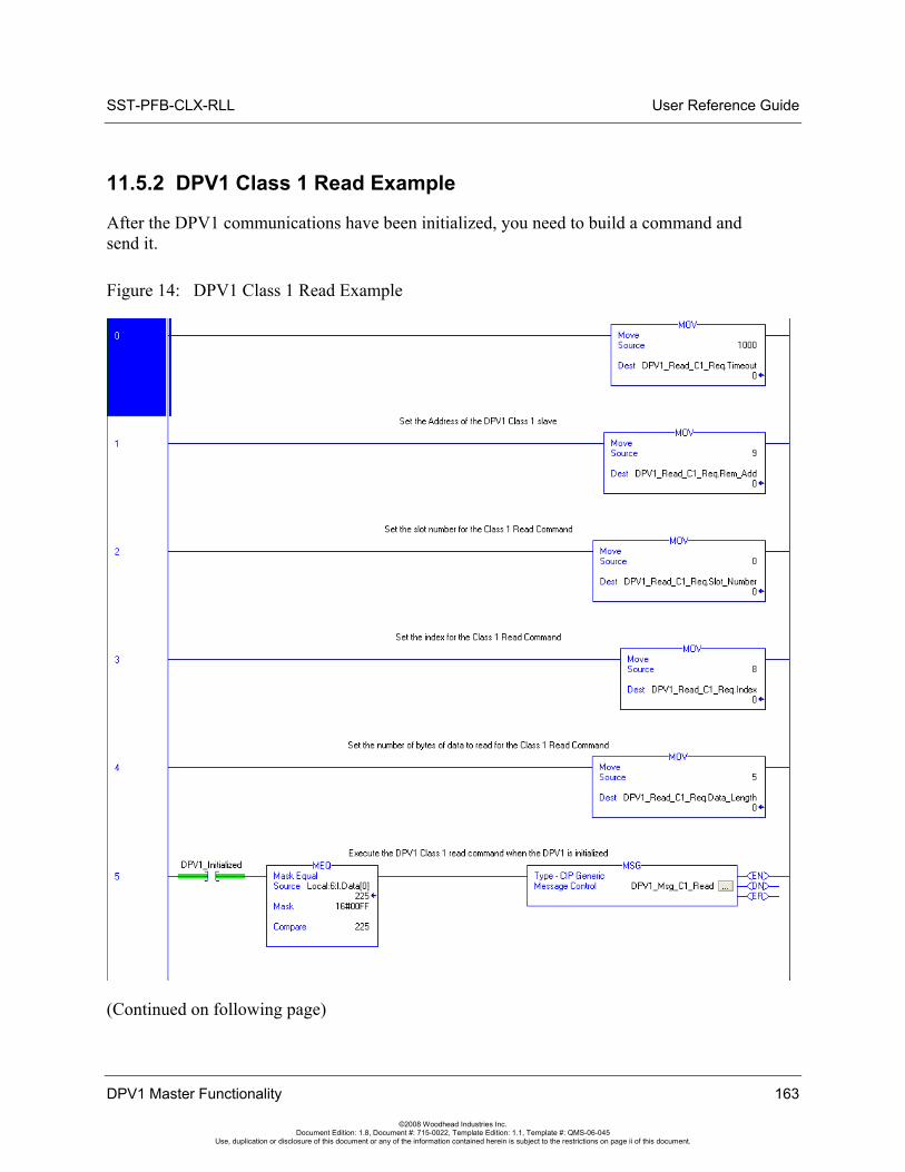
SST-PFB-CLX-RLL User Reference Guide
11.5.2 DPV1 Class 1 Read Example
After the DPV1 communications have been initialized, you need to build a command and send it.
Figure 14: DPV1 Class 1 Read Example
(Continued on following page)
DPV1 Master Functionality 163
©2008 Woodhead Industries Inc. Document Edition: 1.8, Document #: 715-0022, Template Edition: 1.1, Template #: QMS-06-045
Use, duplication or disclosure of this document or any of the information contained herein is subject to the restrictions on page ii of this document.
User Reference Guide SST-PFB-CLX-RLL
(Figure 14, continued).
11.5.3 DPV1 MC2 Initialization Example
This sample logic shows the initialization of the DPV1 Class 2 communications.
Note The only difference between this initialization routine and the one for the Class 1 communication is in Rungs 7 and 8, where the C2_Initiated tag is Unlatched.
164 DPV1 Master Functionality
©2008 Woodhead Industries Inc. Document Edition: 1.8, Document #: 715-0022, Template Edition: 1.1, Template #: QMS-06-045
Use, duplication or disclosure of this document or any of the information contained herein is subject to the restrictions on page ii of this document.
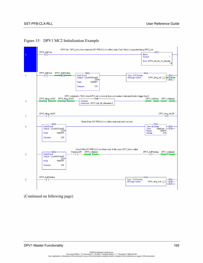
SST-PFB-CLX-RLL User Reference Guide
Figure 15: DPV1 MC2 Initialization Example
(Continued on following page)
DPV1 Master Functionality 165
©2008 Woodhead Industries Inc. Document Edition: 1.8, Document #: 715-0022, Template Edition: 1.1, Template #: QMS-06-045
Use, duplication or disclosure of this document or any of the information contained herein is subject to the restrictions on page ii of this document.
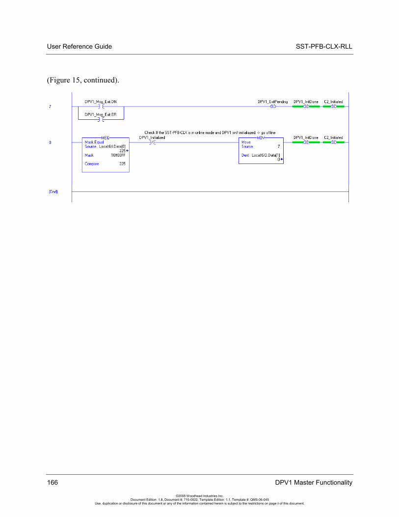
User Reference Guide SST-PFB-CLX-RLL
(Figure 15, continued).
166 DPV1 Master Functionality
©2008 Woodhead Industries Inc. Document Edition: 1.8, Document #: 715-0022, Template Edition: 1.1, Template #: QMS-06-045
Use, duplication or disclosure of this document or any of the information contained herein is subject to the restrictions on page ii of this document.
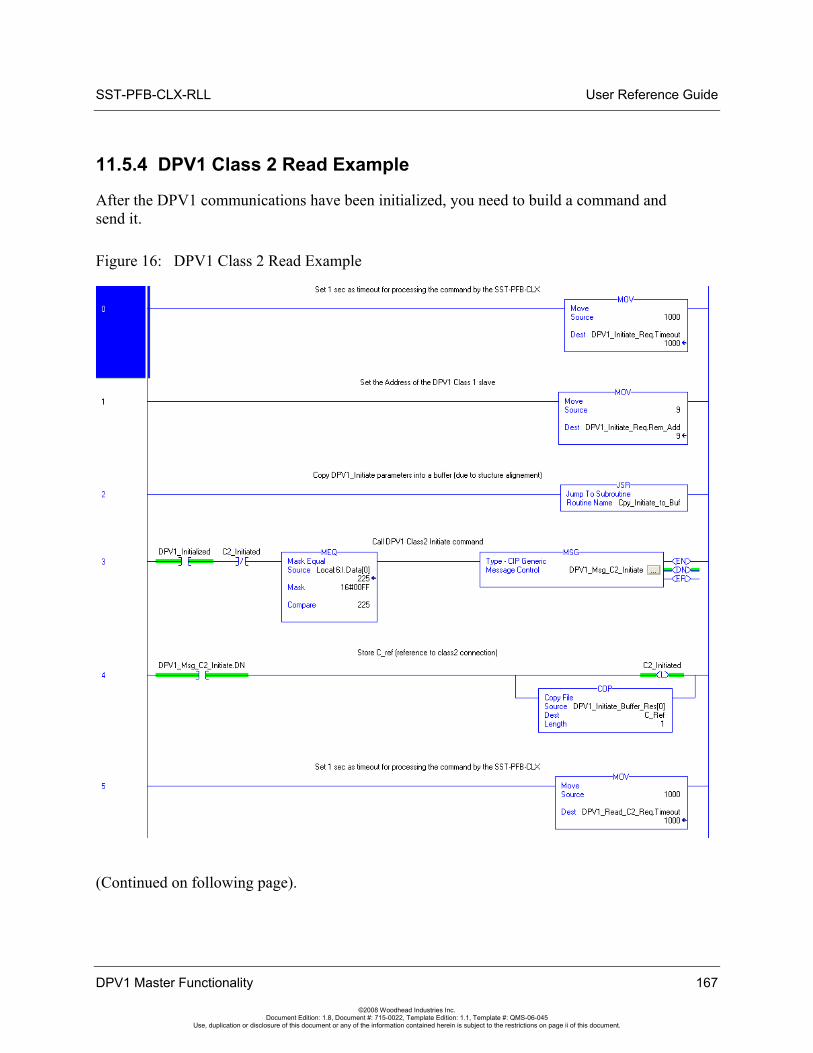
SST-PFB-CLX-RLL User Reference Guide
11.5.4 DPV1 Class 2 Read Example
After the DPV1 communications have been initialized, you need to build a command and send it.
Figure 16: DPV1 Class 2 Read Example
(Continued on following page).
DPV1 Master Functionality 167
©2008 Woodhead Industries Inc. Document Edition: 1.8, Document #: 715-0022, Template Edition: 1.1, Template #: QMS-06-045
Use, duplication or disclosure of this document or any of the information contained herein is subject to the restrictions on page ii of this document.
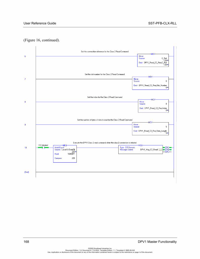
User Reference Guide SST-PFB-CLX-RLL
(Figure 16, continued).
168 DPV1 Master Functionality
©2008 Woodhead Industries Inc. Document Edition: 1.8, Document #: 715-0022, Template Edition: 1.1, Template #: QMS-06-045
Use, duplication or disclosure of this document or any of the information contained herein is subject to the restrictions on page ii of this document.
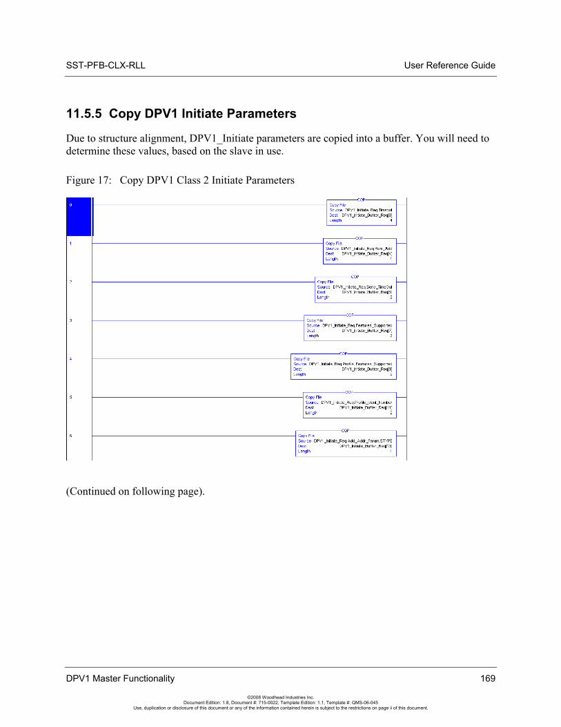
SST-PFB-CLX-RLL User Reference Guide
11.5.5 Copy DPV1 Initiate Parameters
Due to structure alignment, DPV1_Initiate parameters are copied into a buffer. You will need to determine these values, based on the slave in use.
Figure 17: Copy DPV1 Class 2 Initiate Parameters
(Continued on following page).
DPV1 Master Functionality 169
©2008 Woodhead Industries Inc. Document Edition: 1.8, Document #: 715-0022, Template Edition: 1.1, Template #: QMS-06-045
Use, duplication or disclosure of this document or any of the information contained herein is subject to the restrictions on page ii of this document.
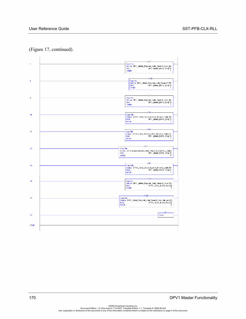
User Reference Guide SST-PFB-CLX-RLL
(Figure 17, continued).
170 DPV1 Master Functionality
©2008 Woodhead Industries Inc. Document Edition: 1.8, Document #: 715-0022, Template Edition: 1.1, Template #: QMS-06-045
Use, duplication or disclosure of this document or any of the information contained herein is subject to the restrictions on page ii of this document.
SST-PFB-CLX-RLL User Reference Guide
Using the Configuration Tool through RSLinx 171
©2008 Woodhead Industries Inc. Document Edition: 1.8, Document #: 715-0022, Template Edition: 1.1, Template #: QMS-06-045
Use, duplication or disclosure of this document or any of the information contained herein is subject to the restrictions on page ii of this document.
12 Using the Configuration Tool through RSLinx
Chapter Sections:
• Configuration Tool Overview
• Functions
• Configuring the RSLinx Connection
• DPV1 Features
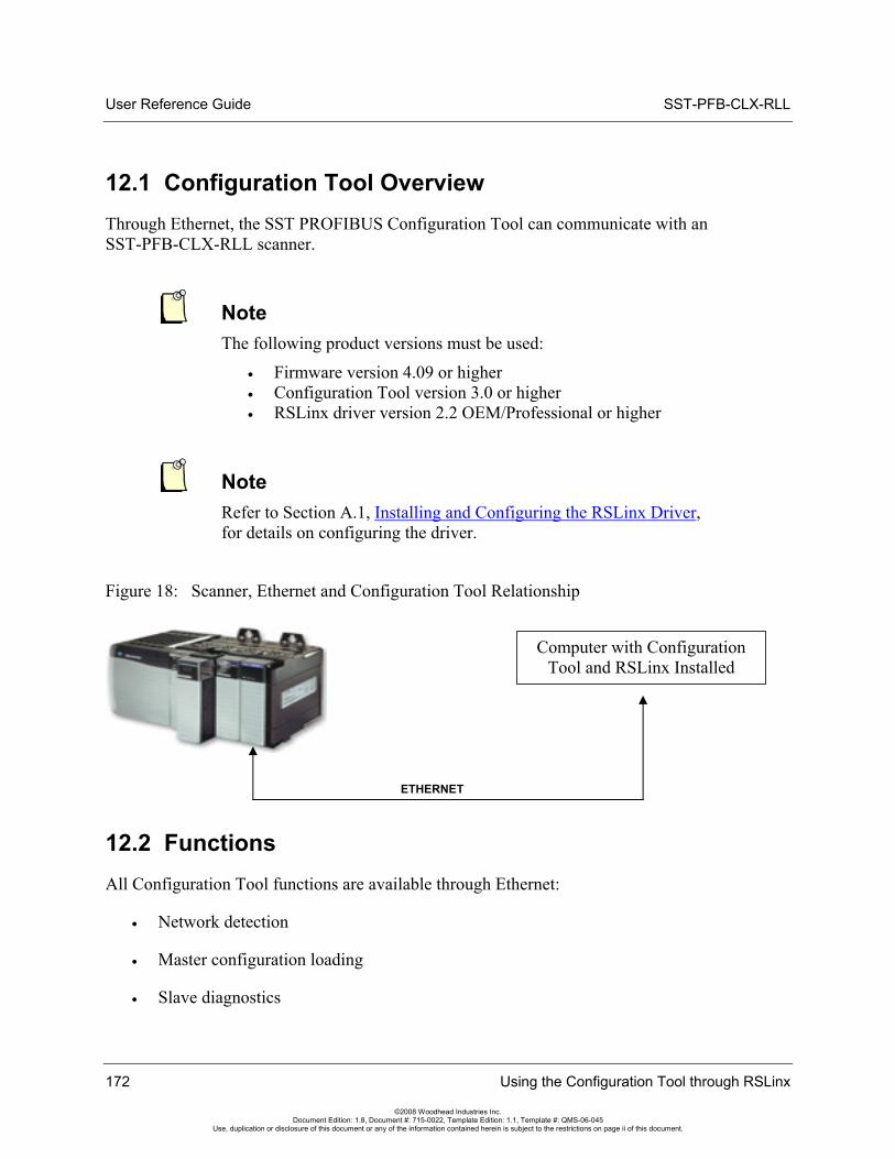
User Reference Guide SST-PFB-CLX-RLL
12.1 Configuration Tool Overview Through Ethernet, the SST PROFIBUS Configuration Tool can communicate with an SST-PFB-CLX-RLL scanner.
Note The following product versions must be used:
• Firmware version 4.09 or higher • Configuration Tool version 3.0 or higher • RSLinx driver version 2.2 OEM/Professional or higher
Note Refer to Section A.1, Installing and Configuring the RSLinx Driver, for details on configuring the driver.
Figure 18: Scanner, Ethernet and Configuration Tool Relationship
Computer with Configuration Tool and RSLinx Installed
ETHERNET
12.2 Functions All Configuration Tool functions are available through Ethernet:
• Network detection
• Master configuration loading
• Slave diagnostics
172 Using the Configuration Tool through RSLinx
©2008 Woodhead Industries Inc. Document Edition: 1.8, Document #: 715-0022, Template Edition: 1.1, Template #: QMS-06-045
Use, duplication or disclosure of this document or any of the information contained herein is subject to the restrictions on page ii of this document.
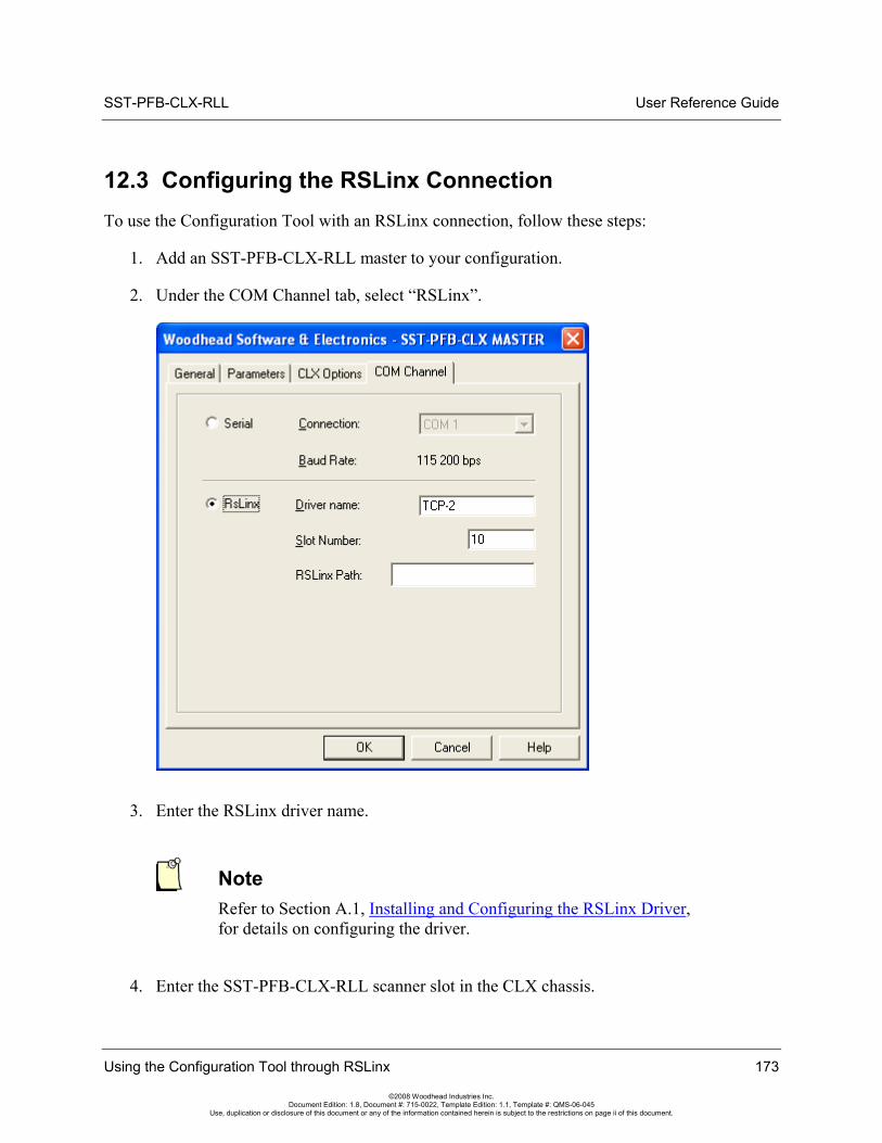
SST-PFB-CLX-RLL User Reference Guide
12.3 Configuring the RSLinx Connection To use the Configuration Tool with an RSLinx connection, follow these steps:
1. Add an SST-PFB-CLX-RLL master to your configuration.
2. Under the COM Channel tab, select “RSLinx”.
3. Enter the RSLinx driver name.
Note Refer to Section A.1, Installing and Configuring the RSLinx Driver, for details on configuring the driver.
4. Enter the SST-PFB-CLX-RLL scanner slot in the CLX chassis.
Using the Configuration Tool through RSLinx 173
©2008 Woodhead Industries Inc. Document Edition: 1.8, Document #: 715-0022, Template Edition: 1.1, Template #: QMS-06-045
Use, duplication or disclosure of this document or any of the information contained herein is subject to the restrictions on page ii of this document.
User Reference Guide SST-PFB-CLX-RLL
5. If the scanner module is in a remote rack, enter the RSLinx path. Here is an example:
The remote Ethernet module is in slot 6 and its address in the remote rack is 130.151.132.1. The SST-PFB-CLX module is in slot 8. So the string would be:
01 06 12 0D 31 33 30 2e 31 35 31 2e 31 33 32 2e 31 00
• 01h = Communication with the backplane
• 06h = Slot of Remote Ethernet module (in local rack)
• 12h = Port Address
• 0Dh= Length Byte (Number of ASCII bytes in IP Address
• 31 33 30 2e 31 35 31 2e 31 33 32 2e 31 00 = (IP Address in ASCII). If the number of bytes in the IP address in ASCII is odd, pad another byte (00h) on the end of the path, like in this example.
Note Configure the remote Ethernet module to browse the IP Address 130.151.132.1 (the IP address is assigned to the Ethernet module in the remote rack) in the remote Ethernet module properties under TCP driver configuration.
6. Click OK to save your configuration.
7. Connect to the scanner by clicking the button or by selecting the Connect command in the master menu.
12.4 DPV1 Features Each slave must be configured to accept DPV1 commands. Using the Configuration Tool:
1. Open the slave's properties.
2. Under the Extended Parameters tab, select the DPV1 option.
3. Save the configuration and load it into the scanner.
174 Using the Configuration Tool through RSLinx
©2008 Woodhead Industries Inc. Document Edition: 1.8, Document #: 715-0022, Template Edition: 1.1, Template #: QMS-06-045
Use, duplication or disclosure of this document or any of the information contained herein is subject to the restrictions on page ii of this document.
SST-PFB-CLX-RLL User Reference Guide
I/O Expansion 175
©2008 Woodhead Industries Inc. Document Edition: 1.8, Document #: 715-0022, Template Edition: 1.1, Template #: QMS-06-045
Use, duplication or disclosure of this document or any of the information contained herein is subject to the restrictions on page ii of this document.
13 I/O Expansion
Chapter Sections:
• I/O Expansion Overview
• Assigning I/O Offsets in Your Configuration
• I/O Expansion Ladder Samples
User Reference Guide SST-PFB-CLX-RLL
13.1 I/O Expansion Overview
Note This functionality was added in firmware version 6.02, Build 1.
The SST-PFB-CLX master supports I/O data up to a maximum of 1984 input bytes and 1968 output bytes within 4 I/O pages. There are 4 bytes reserved for control registers at the beginning of each page. Each input page is 500 bytes and each output page is 496 bytes.
The Host controls which page of I/O is mapped into the ControlLogix I/O table by writing to Byte 1 of the ControlLogix output table. To change the input page, (WORD Data type is used), update the lower nibble of byte 1 (Local:2:O.Data[0].8 – 11) with page number (0 – 3). To change the output page, update the upper nibble of byte 1 (Local:Slot:O.Data[0].12 – 15) with page number (0 -3).
When changing Output Pages, updating the Control register (Local:Slot:I.Data[0].12 – 15) with the output page number and output data at the same time is required before doing a Synchronous Copy to the ControlLogix Output table.
After changing the Input pages, the host should wait for the firmware to set the page number(s) in byte 1 of the Input table (Local:Slot:I.Data[0].8 – 11). Input pages should not be read until the Inputer table’s low nibble of byte 1 (Local:Slot:I.Data[0].8 – 11) is equal to the Output table’s low nibble of byte 1 (Local:Slot:O.Data[0].8 – 11).
To retrieve or update the data on a page, use the CPS instruction (Synchronous Copy File) in the RsLogix 5000 software. With the CPS instruction, an I/O update cannot change the data while you are copying to/from the local buffer. If you plan to read all used input pages into a local buffer prior to processing input data, below is sample logic that would be required to avoid data tearing.
Note The ladder logic samples given are examples only.
176 I/O Expansion
©2008 Woodhead Industries Inc. Document Edition: 1.8, Document #: 715-0022, Template Edition: 1.1, Template #: QMS-06-045
Use, duplication or disclosure of this document or any of the information contained herein is subject to the restrictions on page ii of this document.
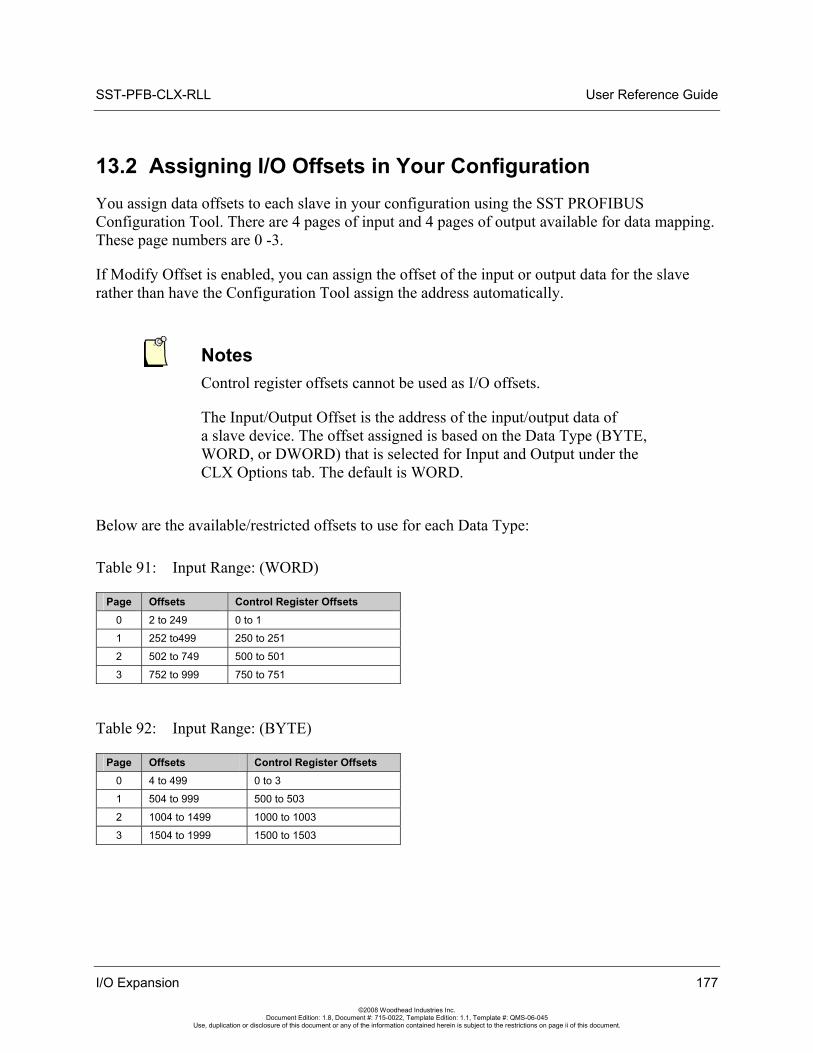
SST-PFB-CLX-RLL User Reference Guide
13.2 Assigning I/O Offsets in Your Configuration You assign data offsets to each slave in your configuration using the SST PROFIBUS Configuration Tool. There are 4 pages of input and 4 pages of output available for data mapping. These page numbers are 0 -3.
If Modify Offset is enabled, you can assign the offset of the input or output data for the slave rather than have the Configuration Tool assign the address automatically.
Notes Control register offsets cannot be used as I/O offsets.
The Input/Output Offset is the address of the input/output data of a slave device. The offset assigned is based on the Data Type (BYTE, WORD, or DWORD) that is selected for Input and Output under the CLX Options tab. The default is WORD.
Below are the available/restricted offsets to use for each Data Type:
Table 91: Input Range: (WORD)
Page Offsets Control Register Offsets 0 2 to 249 0 to 1
1 252 to499 250 to 251
2 502 to 749 500 to 501
3 752 to 999 750 to 751
Table 92: Input Range: (BYTE)
Page Offsets Control Register Offsets 0 4 to 499 0 to 3
1 504 to 999 500 to 503
2 1004 to 1499 1000 to 1003
3 1504 to 1999 1500 to 1503
I/O Expansion 177
©2008 Woodhead Industries Inc. Document Edition: 1.8, Document #: 715-0022, Template Edition: 1.1, Template #: QMS-06-045
Use, duplication or disclosure of this document or any of the information contained herein is subject to the restrictions on page ii of this document.
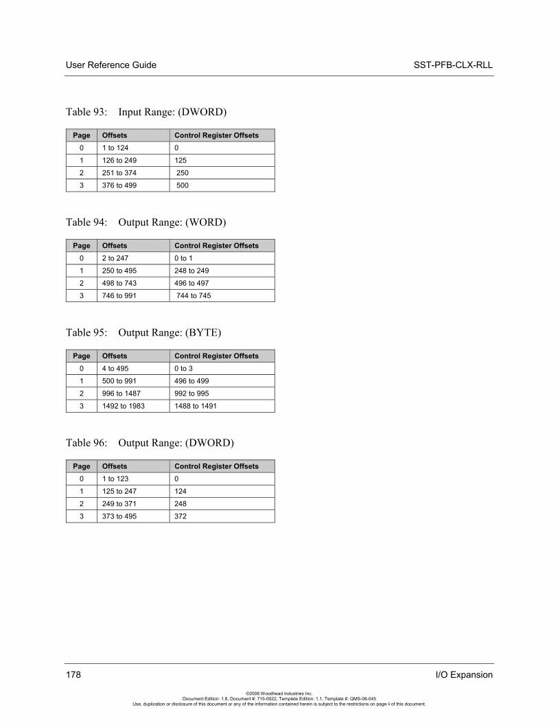
User Reference Guide SST-PFB-CLX-RLL
178 I/O Expansion
©2008 Woodhead Industries Inc. Document Edition: 1.8, Document #: 715-0022, Template Edition: 1.1, Template #: QMS-06-045
Use, duplication or disclosure of this document or any of the information contained herein is subject to the restrictions on page ii of this document.
Table 93: Input Range: (DWORD)
Page Offsets Control Register Offsets 0 1 to 124 0
1 126 to 249 125
2 251 to 374 250
3 376 to 499 500
Table 94: Output Range: (WORD)
Page Offsets Control Register Offsets 0 2 to 247 0 to 1
1 250 to 495 248 to 249
2 498 to 743 496 to 497
3 746 to 991 744 to 745
Table 95: Output Range: (BYTE)
Page Offsets Control Register Offsets 0 4 to 495 0 to 3
1 500 to 991 496 to 499
2 996 to 1487 992 to 995
3 1492 to 1983 1488 to 1491
Table 96: Output Range: (DWORD)
Page Offsets Control Register Offsets 0 1 to 123 0
1 125 to 247 124
2 249 to 371 248
3 373 to 495 372
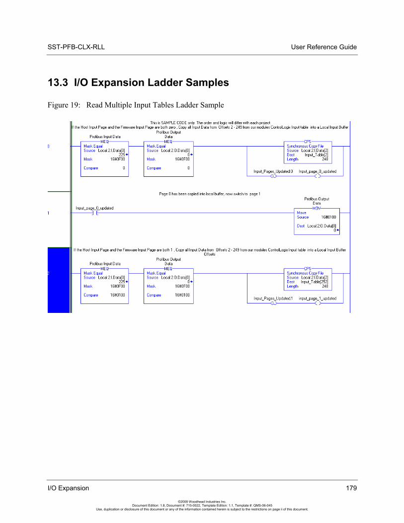
SST-PFB-CLX-RLL User Reference Guide
13.3 I/O Expansion Ladder Samples
Figure 19: Read Multiple Input Tables Ladder Sample
I/O Expansion 179
©2008 Woodhead Industries Inc. Document Edition: 1.8, Document #: 715-0022, Template Edition: 1.1, Template #: QMS-06-045
Use, duplication or disclosure of this document or any of the information contained herein is subject to the restrictions on page ii of this document.
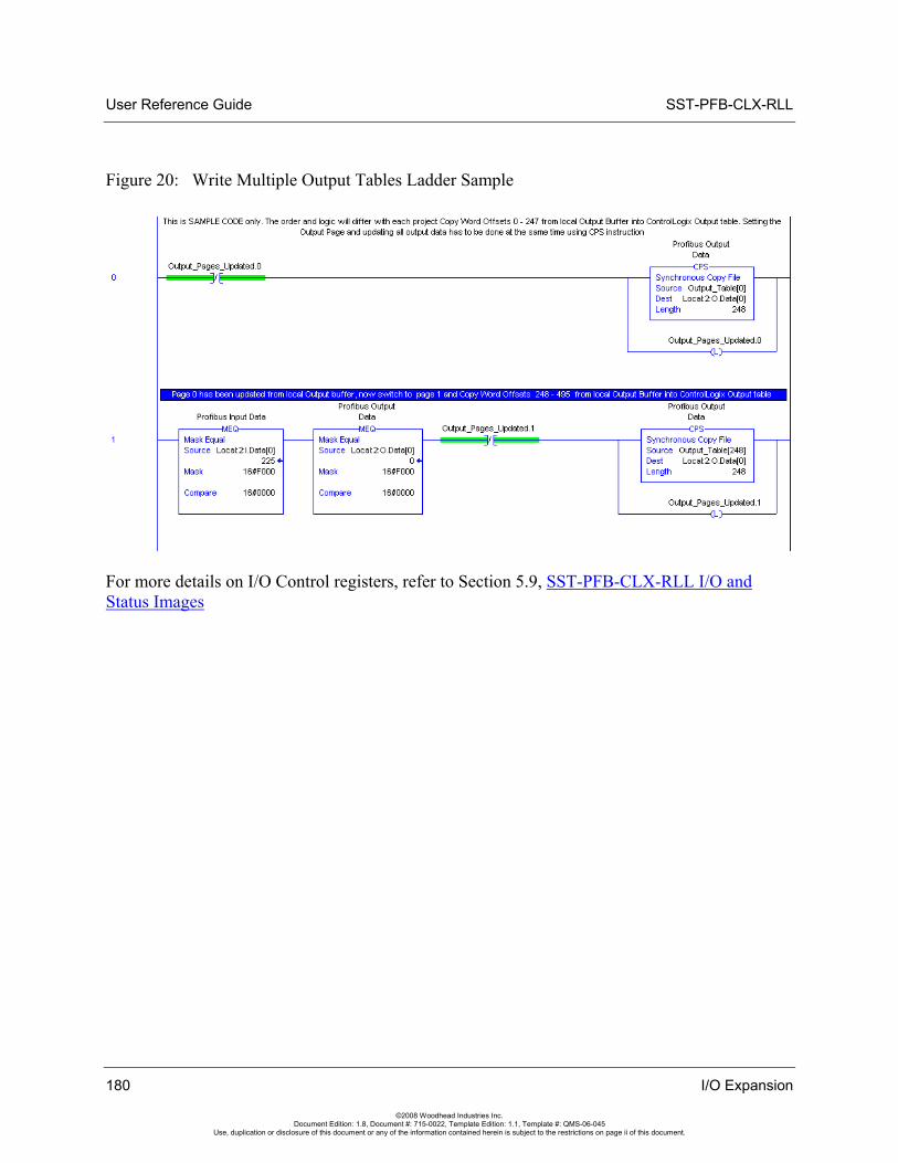
User Reference Guide SST-PFB-CLX-RLL
Figure 20: Write Multiple Output Tables Ladder Sample
For more details on I/O Control registers, refer to Section 5.9, SST-PFB-CLX-RLL I/O and Status Images
180 I/O Expansion
©2008 Woodhead Industries Inc. Document Edition: 1.8, Document #: 715-0022, Template Edition: 1.1, Template #: QMS-06-045
Use, duplication or disclosure of this document or any of the information contained herein is subject to the restrictions on page ii of this document.
SST-PFB-CLX-RLL User Reference Guide
A Setting up the RSLinx Driver
Appendix Sections:
• Installing and Configuring the RSLinx Driver
Note This Appendix assumes that you are using RSLinx software OEM/Professional, version 2.2.
Setting up the RSLinx Driver 181
©2008 Woodhead Industries Inc. Document Edition: 1.8, Document #: 715-0022, Template Edition: 1.1, Template #: QMS-06-045
Use, duplication or disclosure of this document or any of the information contained herein is subject to the restrictions on page ii of this document.
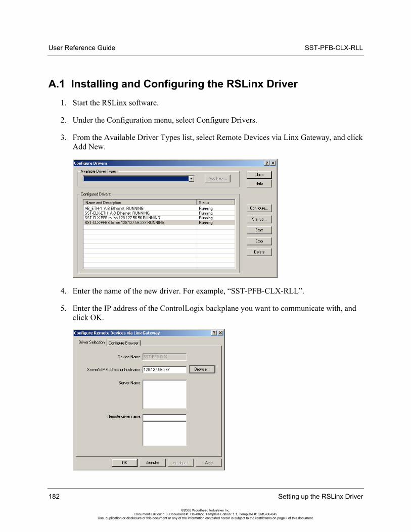
User Reference Guide SST-PFB-CLX-RLL
A.1 Installing and Configuring the RSLinx Driver 1. Start the RSLinx software.
2. Under the Configuration menu, select Configure Drivers.
3. From the Available Driver Types list, select Remote Devices via Linx Gateway, and click Add New.
4. Enter the name of the new driver. For example, “SST-PFB-CLX-RLL”.
5. Enter the IP address of the ControlLogix backplane you want to communicate with, and click OK.
182 Setting up the RSLinx Driver
©2008 Woodhead Industries Inc. Document Edition: 1.8, Document #: 715-0022, Template Edition: 1.1, Template #: QMS-06-045
Use, duplication or disclosure of this document or any of the information contained herein is subject to the restrictions on page ii of this document.
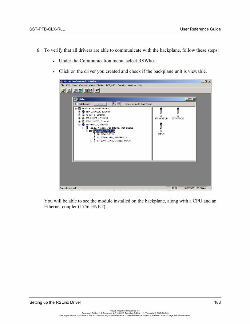
SST-PFB-CLX-RLL User Reference Guide
6. To verify that all drivers are able to communicate with the backplane, follow these steps:
• Under the Communication menu, select RSWho.
• Click on the driver you created and check if the backplane unit is viewable.
You will be able to see the module installed on the backplane, along with a CPU and an Ethernet coupler (1756-ENET).
Setting up the RSLinx Driver 183
©2008 Woodhead Industries Inc. Document Edition: 1.8, Document #: 715-0022, Template Edition: 1.1, Template #: QMS-06-045
Use, duplication or disclosure of this document or any of the information contained herein is subject to the restrictions on page ii of this document.

User Reference Guide SST-PFB-CLX-RLL
184 Setting up the RSLinx Driver
©2008 Woodhead Industries Inc. Document Edition: 1.8, Document #: 715-0022, Template Edition: 1.1, Template #: QMS-06-045
Use, duplication or disclosure of this document or any of the information contained herein is subject to the restrictions on page ii of this document.
SST-PFB-CLX-RLL User Reference Guide
Technical Specifications 185
©2008 Woodhead Industries Inc. Document Edition: 1.8, Document #: 715-0022, Template Edition: 1.1, Template #: QMS-06-045
Use, duplication or disclosure of this document or any of the information contained herein is subject to the restrictions on page ii of this document.
B Technical Specifications
Appendix Sections:
• Technical Specifications
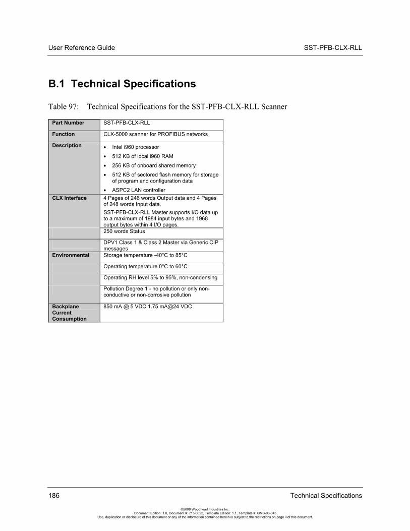
User Reference Guide SST-PFB-CLX-RLL
186 Technical Specifications
©2008 Woodhead Industries Inc. Document Edition: 1.8, Document #: 715-0022, Template Edition: 1.1, Template #: QMS-06-045
Use, duplication or disclosure of this document or any of the information contained herein is subject to the restrictions on page ii of this document.
B.1 Technical Specifications
Table 97: Technical Specifications for the SST-PFB-CLX-RLL Scanner
Part Number SST-PFB-CLX-RLL
Function CLX-5000 scanner for PROFIBUS networks
Description • Intel i960 processor
• 512 KB of local i960 RAM
• 256 KB of onboard shared memory
• 512 KB of sectored flash memory for storage of program and configuration data
• ASPC2 LAN controller CLX Interface 4 Pages of 246 words Output data and 4 Pages
of 248 words Input data. SST-PFB-CLX-RLL Master supports I/O data up to a maximum of 1984 input bytes and 1968 output bytes within 4 I/O pages.
250 words Status
DPV1 Class 1 & Class 2 Master via Generic CIP messages
Environmental Storage temperature -40°C to 85°C
Operating temperature 0°C to 60°C
Operating RH level 5% to 95%, non-condensing
Pollution Degree 1 - no pollution or only non-conductive or non-corrosive pollution
Backplane Current Consumption
850 mA @ 5 VDC 1.75 mA@24 VDC
SST-PFB-CLX-RLL User Reference Guide
CE Compliance 187
©2008 Woodhead Industries Inc. Document Edition: 1.8, Document #: 715-0022, Template Edition: 1.1, Template #: QMS-06-045
Use, duplication or disclosure of this document or any of the information contained herein is subject to the restrictions on page ii of this document.
C CE Compliance
Appendix Sections:
• CE Compliance
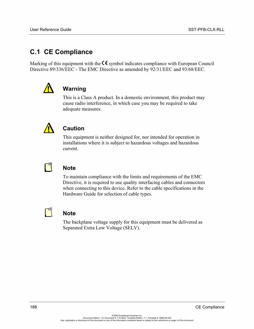
User Reference Guide SST-PFB-CLX-RLL
C.1 CE Compliance Marking of this equipment with the symbol indicates compliance with European Council Directive 89/336/EEC - The EMC Directive as amended by 92/31/EEC and 93/68/EEC.
Warning This is a Class A product. In a domestic environment, this product may cause radio interference, in which case you may be required to take adequate measures.
Caution This equipment is neither designed for, nor intended for operation in installations where it is subject to hazardous voltages and hazardous current.
Note To maintain compliance with the limits and requirements of the EMC Directive, it is required to use quality interfacing cables and connectors when connecting to this device. Refer to the cable specifications in the Hardware Guide for selection of cable types.
Note The backplane voltage supply for this equipment must be delivered as Separated Extra Low Voltage (SELV).
188 CE Compliance
©2008 Woodhead Industries Inc. Document Edition: 1.8, Document #: 715-0022, Template Edition: 1.1, Template #: QMS-06-045
Use, duplication or disclosure of this document or any of the information contained herein is subject to the restrictions on page ii of this document.
SST-PFB-CLX-RLL User Reference Guide
Warranty and Support 189
©2008 Woodhead Industries Inc. Document Edition: 1.8, Document #: 715-0022, Template Edition: 1.1, Template #: QMS-06-045
Use, duplication or disclosure of this document or any of the information contained herein is subject to the restrictions on page ii of this document.
D Warranty and Support
Appendix Sections:
• Warranty
• Reference Documents
• Technical Support
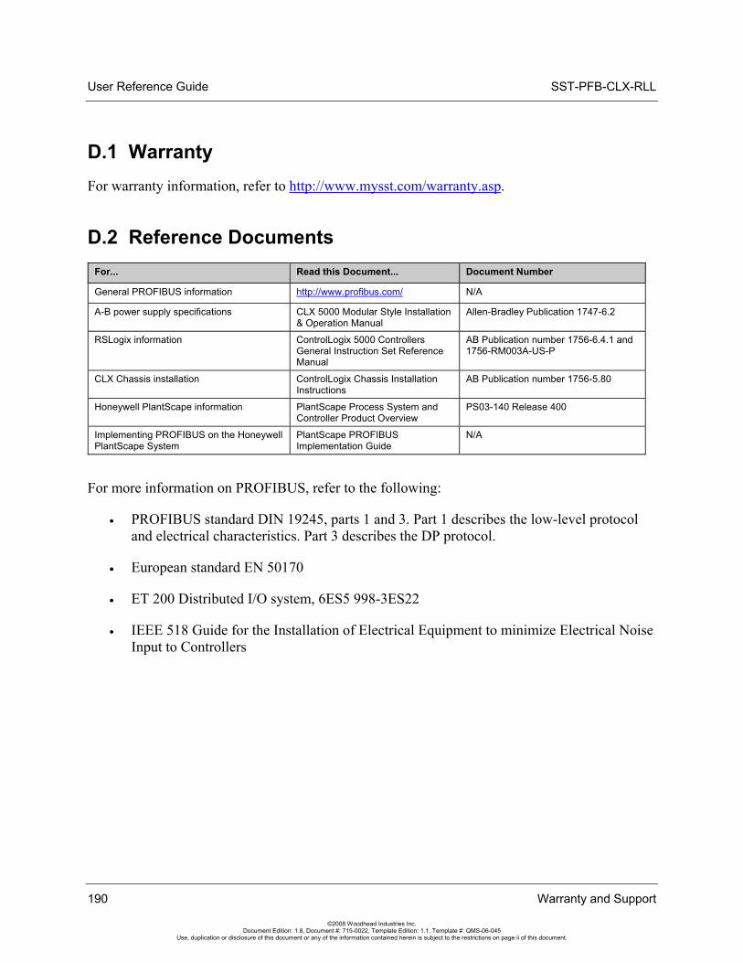
User Reference Guide SST-PFB-CLX-RLL
190 Warranty and Support
©2008 Woodhead Industries Inc. Document Edition: 1.8, Document #: 715-0022, Template Edition: 1.1, Template #: QMS-06-045
Use, duplication or disclosure of this document or any of the information contained herein is subject to the restrictions on page ii of this document.
D.1 Warranty For warranty information, refer to http://www.mysst.com/warranty.asp.
D.2 Reference Documents For... Read this Document... Document Number
General PROFIBUS information http://www.profibus.com/ N/A
A-B power supply specifications CLX 5000 Modular Style Installation & Operation Manual
Allen-Bradley Publication 1747-6.2
RSLogix information ControlLogix 5000 Controllers General Instruction Set Reference Manual
AB Publication number 1756-6.4.1 and 1756-RM003A-US-P
CLX Chassis installation ControlLogix Chassis Installation Instructions
AB Publication number 1756-5.80
Honeywell PlantScape information PlantScape Process System and Controller Product Overview
PS03-140 Release 400
Implementing PROFIBUS on the Honeywell PlantScape System
PlantScape PROFIBUS Implementation Guide
N/A
For more information on PROFIBUS, refer to the following:
• PROFIBUS standard DIN 19245, parts 1 and 3. Part 1 describes the low-level protocol and electrical characteristics. Part 3 describes the DP protocol.
• European standard EN 50170
• ET 200 Distributed I/O system, 6ES5 998-3ES22
• IEEE 518 Guide for the Installation of Electrical Equipment to minimize Electrical Noise Input to Controllers
SST-PFB-CLX-RLL User Reference Guide
Warranty and Support 191
©2008 Woodhead Industries Inc. Document Edition: 1.8, Document #: 715-0022, Template Edition: 1.1, Template #: QMS-06-045
Use, duplication or disclosure of this document or any of the information contained herein is subject to the restrictions on page ii of this document.
D.3 Technical Support Please ensure that you have the following information readily available before calling for Technical Support:
• Card type and serial number
• Computer's make, model, CPU speed and hardware configuration (other cards installed)
• Operating system type and version
• Details of the problem you are experiencing: firmware module type and version, target network and circumstances that may have caused the problem
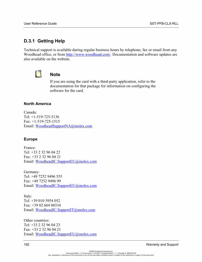
User Reference Guide SST-PFB-CLX-RLL
D.3.1 Getting Help
Technical support is available during regular business hours by telephone, fax or email from any Woodhead office, or from http://www.woodhead.com/. Documentation and software updates are also available on the website.
Note If you are using the card with a third-party application, refer to the documentation for that package for information on configuring the software for the card.
North America
Canada: Tel: +1-519-725-5136 Fax: +1-519-725-1515 Email: [email protected]
Europe
France: Tel: +33 2 32 96 04 22 Fax: +33 2 32 96 04 21 Email: [email protected]
Germany: Tel: +49 7252 9496 555 Fax: +49 7252 9496 99 Email: [email protected]
Italy: Tel: +39 010 5954 052 Fax: +39 02 664 00334 Email: [email protected]
Other countries: Tel: +33 2 32 96 04 23 Fax: +33 2 32 96 04 21 Email: [email protected]
192 Warranty and Support
©2008 Woodhead Industries Inc. Document Edition: 1.8, Document #: 715-0022, Template Edition: 1.1, Template #: QMS-06-045
Use, duplication or disclosure of this document or any of the information contained herein is subject to the restrictions on page ii of this document.
SST-PFB-CLX-RLL User Reference Guide
Warranty and Support 193
©2008 Woodhead Industries Inc. Document Edition: 1.8, Document #: 715-0022, Template Edition: 1.1, Template #: QMS-06-045
Use, duplication or disclosure of this document or any of the information contained herein is subject to the restrictions on page ii of this document.
Asia-Pacific
Japan: Tel: +81 52 221 5950 Fax: +81 46 265 2429 Email: [email protected]
Singapore: Tel: +65 6268 6868 Fax: +65 6261 3588 Email: [email protected]
China: Tel: +86 21 5835 9885 Fax: +86 21 5835 9980 Email: [email protected]
For the most current contact details, please visit http://www.woodhead.com.


![[Logix] Bài 5_ Rslinx Classic _ JAP](https://img.dokumen.tips/doc/110x75/55cf8f61550346703b9bcc62/logix-bai-5-rslinx-classic-jap.jpg)