Embed Size (px)
Citation preview

Doctoral Thesis in Machine Design
Motion Planning and Control of Automated Vehicles in Critical SituationsLARS SVENSSON
Stockholm, Sweden 2021www.kth.se
ISBN: 978-91-7873-891-5TRITA-ITM-AVL 2021:23
KTH ROYAL INSTITUTE OF TECHNOLOGY
LARS SVENSSON M
otion Planning and Control of Automated Vehicles in Critical Situations
KTH
2021

Motion Planning and Control of Automated Vehicles in Critical SituationsLARS SVENSSON
Doctoral Thesis in Machine DesignKTH Royal Institute of TechnologyStockholm, Sweden 2021
Academic Dissertation which, with due permission of the KTH Royal Institute of Technology, is submitted for public defence for the Degree of Doctor of Philosophy on Tuesday the 8th June 2021, at 3:00 p.m. in U1, Brinellvägen 28A, Stockholm.

© Lars Svensson ISBN: 978-91-7873-891-5TRITA-ITM-AVL 2021:23 Printed by: Universitetsservice US-AB, Sweden 2021

iii
Abstract
The road traffic environment is inherently uncertain and unpredictable.An automated vehicle (AV) deployed in such an environment will eventuallyexperience unforeseen critical situations, i.e., situations in which the probabil-ity of having an accident is rapidly increased compared to a nominal drivingsituation. Critical situations can occur for example due to internal faults orperformance limitations of the AV, abrupt changes in operational conditionsor unexpected behavior from other road users. In such critical situations, thefirst priority for vehicle motion control is to reduce the risk of imminent acci-dent. If needed, the full physical capacity of the vehicle should be employed toaccomplish this. These unique circumstances distinguish automated drivingin critical situations from the nominal case.
This work aims to tackle the problem of motion planning and control insuch critical situations. We determine a set of characteristics that signifythe motion planning and control problem in critical situations, in relationto state of the art algorithms. Further, we incrementally develop a motionplanning and control framework, tailored for the particular circumstances ofcritical situations. In its current form, the framework uses a combinationof numerical optimization, trajectory rollout and constraint adaptation, toallow motion planning and control with respect to time-varying actuationcapabilities, while realizing a range of behaviors to mitigate accident risk ina range of critical situations.
Results for the research work are generated by exposing the frameworkto several categories of critical situations in a combination of simulations andfull scale vehicle tests. We present the following main findings: (1) Inclu-sion of risk levels of stopping locations at the local planning level generatessatisfactory motion behavior in the evaluated critical situations, enabling acombined assessment of risk of the maneuver and of the stopping location.(2) Traction adaptive motion planning and control improves the capacity ofautonomous vehicles to reduce accident risk in critical situations, both whenadapting to deteriorated and when adapting to improved traction in a rangeof tested critical situations. (3) State of the art friction estimation algorithmsare insufficient for traction adaptive motion planning in terms of combinedrequirements on accuracy, availability and foresight. However, fusion of mul-tiple estimation paradigms show potential to yield near-optimal performance.
The combined contributions of this thesis are intended as a step towardsfurther improving accident avoidance performance of automated vehicles anddriver assistance systems in critical situations. However, much research workremains to be done in this field. We emphasize the need for further researchefforts in terms of experimentally evaluating the impact of motion planningand control concepts on accident avoidance performance in critical situations.

iv
Sammanfattning
Vägtrafikmiljön är oförutsägbar. Autonoma vägfordon i en sådan miljökommer tids nog att hamna i oförutsedda kritiska situationer, det vill sägasituationer där risken för en trafikolycka är markant högre än vid nominellkörning. Kritiska situationer kan orsakas av exempelvis interna fel eller pre-standabegränsningar hos autonomisystemet, av plötsliga förändringar i opera-tionella förhållanden eller av oförutsett agerande hos medtrafikanter. I kritiskasituationer är passagerarkomfort inte längre en prioritet, utan fordonets full-ständiga manöverförmåga kan utnyttjas för att minimera olycksrisken. Dessaomständigheter skiljer autonom körning i kritiska situationer från det nomi-nella fallet.
Forskningsinriktningen för denna avhandling är rörelseplanering och styr-ning av autonoma fordon i kritiska situationer. Vi presenterar en uppsättningegenskaper som kännetecknar detta specifika problem, i relation till ledandealgoritmer för rörelseplanering och styrning. Vi presenterar också vår egenstegvis utvecklade metod för att angripa problemet. I sin nuvarande form be-står metoden av en kombination av optimeringsbaserad och samplingsbaseradtrajektorieplanering med tidsvarierande dynamik och bivillkor. Metoden gördet möjligt att representera tidsvarierande dynamik och dynamiska begräns-ningar hos fordonet (till exempel till följd av varierande vägförhållanden) vidplanering av en mängd olika manövertyper som kan minska olycksrisken ikritiska situationer.
Resultaten i forskningsarbetet har genererats genom att testa metoden iett flertal typer av kritiska situationer som har iscensatts genom en kombi-nation av simuleringsmiljöer och experiment med fullskaliga autonoma test-fordon. De huvudsakliga slutsatserna från forskningsarbetet är följande: (1)Att inkludera risknivån hos alternativa stoppositioner på den lokala plane-ringsnivån genererar tillfredsställande rörelsebeteende vid exempelvis internafel hos autonomisystemet. Detta möjliggör en sammantagen riskbedömningför manöver och stopposition. (2) Väglagsanpassad rörelseplanering och styr-ning förbättrar autonoma fordons förmåga att reducera olycksrisk i kritiskasituationer, både vid anpassning till försämrade och till förbättrade vägför-hållanden. (3) Ledande metoder för skattning av vägfriktion har inte tillfred-ställande prestanda för väglagsanpassad rörelseplanering och styrning medavseende på kombinerade krav på precision, tillgänglighet och framsynthet,när de används var för sig. Dock är det möjligt att kombinera estimat frånolika sensorslag till ett friktionsestimat som ger närmast optimalt rörelsebe-teende då det används i kombination med väglagsanpassad rörelseplaneringoch styrning.
Vår förhoppning är att de sammanlagda forskningsbidragen från denna av-handling kan komma att bidra till fortsatta prestandaförbättringar hos systemavsedda att minska olycksrisken i kritiska situationer, både för autonoma for-don och för förarstödsystem. Det finns dock mycket kvar att göra inom dettaforskningsfält. Vi vill särskilt framhäva behovet av ytterligare forskningsini-tiativ rörande experimentell utvärdering av nya koncept för rörelseplaneringoch styrning, med avseende på förmågan att minska olycksrisken i kritiskasituationer.

v
Acknowledgements
First of all, I would like to thank my supervisor Prof. Martin Törngren and Headof Department Prof. Martin Edin Grimheden for your steadfast support, guidanceand encouragement through thick and thin. Thank you both for believing in mefrom day one, and for providing us at the department with an endless stream ofnew opportunities and a massively creative work environment. I also wish to thankmy co-supervisors Lei Feng and Anna Pernestål Brenden, for your guidance andadvice. I wish to express my utmost gratitude toward the army of PhD studentsand postdocs that provided additional guidance and inspiration throughout theprocess, and thereby gradually helped me in the process of forming my own iden-tity as a researcher. Thank you Monimoy Bujarbaruah, Erik Ward, Rui Oliveira,Gonçalo Collares Pereira, Max Åstrand, Sagar Behere, Nitin Kapania, Ugo Rosolia,George Xiaojing Zhang, John Subosits, Jonathan Goh, Kristoffer Bergman, OskarLjungqvist, Victor Fors, Ivo Batcovic, Xinhai Zhang, Fredrik Asplund, NaveenMohan, Lola Masson, Damir Nesic, Masoumeh Parseh, Binbin Lian, Gustav Stenand José Manuel Gaspar Sánchez. Also, special thanks to, Martin, Lei, Rui, José,Masoumeh and Yvette for helping out with the final rounds of proofreading thethesis.
I was first introduced to the magical world of mechatronics and robotics duringan exchange year at Colorado University Boulder in 2012/13. The combination ofmath, computers, electronics and mechanics that made machines move by them-selves utterly fascinated me back then, and it still does today. Since that time Ihave done little other than trying to learn as much as possible about how to buildmachines that can operate by themselves. I wish to thank Prof. Derek Reamon atColorado University, Prof. Thomas Schön at Uppsala University and Dr. Moham-mad Ali, then at Volvo Cars where I did my MSc thesis project, for sequentiallyand independent of each other inspiring me and motivating me to pursue a PhD inMechatronics and Automated Driving.
During my time at KTH, I have had the privilege to work on several full scaleautonomous vehicle projects which apart from having been loads of fun, gradu-ally thought me some of the craftsmanship and organizational skill that goes intobuilding a large autonomous machine. I would like to thank all the people whoparticipated in those projects: First, thanks to all the participants of the KTHGCDC-2016 team, Stefanos Kokogias, Rui Oliveira, Gonçalo Collares Pereira, Xin-hai Zhang, Xinwu Song, Jonathan Fagerström, Chris Tamimi, Henrik Pettersonand Jonas Mårtensson for a great adventure, with great friends. Second, thanksto all who continued to work on autonomous functionality for the KTH ResearchConcept Vehicle, Erik Ward, Gonçalo Collares Pereira, Jonas Krook and Yuchao Li.Third, thanks everyone who participated in finally making the traction adaptivemotion planning experiments happen: Arpit Karsolia, Christian Berger, Fredrikvon Corswant, Henrik Biswanger and Ola Mattson. This project team worked likea well-oiled machine, sorting out one show-stopping problem after another like no-body’s business. Thanks also to the organizations that provided extra funding for

vi
the experiments: The SAFER Open Research at Astazero Program and the Inte-grated Transport Research Lab at KTH. Fourth, thanks to all the participants inthe autonomous forwarder project Auto2: Björn Möller, Gustav Sten, Tobias Sem-berg, Morgan Rossander, Olle Gelin and others. This project opened my eyes tothe opportunities and research challenges of autonomous machines for sustainableforestry - towards which I aim to direct my future efforts.
During my time as a PhD student, I have had the privilege to participate inthe Wallenberg AI, Autonomous Systems and Software Program (WASP) graduateschool, which have provided me with rewarding coursework, amazing study-tripsto world-leading robotics labs in academia and industry, and most importantly avast network of colleagues and friends across the country and the world. Throughthe WASP program I had the opportunity to do a six month research visit to theModel Predictive Control Lab at UC Berkeley. I would like to express my gratitudetoward Prof. Francesco Borrelli for giving me the opportunity, and give a specialthanks to Monimoy Bujarbaruah, Ugo Rosolia, George Xiaojing Zhang and NitinKapania for welcoming me into the research group and for a wonderful researchexchange.
Finally and most important of all, I would like to thank my family and myfriends. Without your unconditional love and support through the good times andthe bad times, none of this would have been possible. Above all, thank you Yvette.I love you, and you are my favorite colleague at the home office. A final specialthanks goes to my second favorite colleague at the home office, our cat Mårtensson,for contributing to the writing by stepping/sitting/sleeping on my keyboard andoccasionally attacking my toes to help me keep awake during lengthy sessions ofthesis-writing.
Lars Svensson,Mörby, May 10, 2021

vii
List of Papers
The thesis is based on the following four publications:
Paper A: L. Svensson, L. Masson, N. Mohan, E. Ward, A. Pernestål Brenden,L. Feng, M. Törngren, ”Safe Stop Trajectory Planning for Highly AutomatedVehicles: An Optimal Control Problem Formulation” 2018 IEEE IntelligentVehicles Symposium (IV), pp. 517-522, Changshu, China.
Paper B: L. Svensson, M. Bujarbaruah, N. R. Kapania and M. Törngren,”Adaptive Trajectory Planning and Optimization at Limits of Handling”,2019 IEEE/RSJ International Conference on Intelligent Robots and Systems(IROS), pp. 3942-3948, Macau, China.
Paper C: L. Svensson, M. Bujarbaruah, A. Karsolia, C. Berger and M.Törngren, ”Traction Adaptive Motion Planning and Control at the Limits ofHandling”, under review for possible journal publication, 2020.
Paper D: L. Svensson and M. Törngren, ”Fusion of Heterogeneous FrictionEstimates for Traction Adaptive Motion Planning and Control”, submittedfor possible conference publication, 2021.
Contributions and responsibilities of the author for each individual appended paperis summarized in Section 3.3. In addition, the author has contributed to writingthe following publications during the course of the PhD studies:
S. Annell, A. Gratner and L. Svensson, ”Probabilistic collision estimationsystem for autonomous vehicles,” 2016 IEEE International Conference on In-telligent Transportation Systems (ITSC), pp. 473-478, Rio de Janeiro, Brazil.
G. C. Pereira, L. Svensson, P. F. Lima and J. Mårtensson, ”Lateral ModelPredictive Control for Over-Actuated Autonomous Vehicle”, 2017 IEEE In-telligent Vehicles Symposium (IV), pp. 310-316, Los Angeles, CA.
S. Kokogias, L. Svensson, G. C. Pereira, R. Oliveira, X. Zhang, X. Song,J. Mårtensson, ”Development of Platform-Independent System for Coopera-tive Automated Driving Evaluated in GCDC 2016”. IEEE Transactions onIntelligent Transportation Systems, vol. 19, no. 4, pp. 1277-1289, April 2018.
J. Krook, L. Svensson, Y. Li, L. Feng and M. Fabian, ”Design and FormalVerification of a Safe Stop Supervisor for an Automated Vehicle”, 2019 In-ternational Conference on Robotics and Automation (ICRA), pp. 5607-5613,Montreal, QC, Canada.
M. Törngren, X. Zhang, N. Mohan, M. Becker, L. Svensson, X. Tao, DJ.Chen, J. Westman, ”Architecting Safety Supervisors for High Levels of Auto-mated Driving”, 2018 International Conference on Intelligent TransportationSystems (ITSC), pp. 1721-1728, Maui, USA.

viii
D. Chen, Z. Yang, L. Svensson and L. Feng, ”Optimization based path plan-ning for a two-body articulated vehicle”, 2020 IEEE International Conferenceon Automation Science and Engineering (CASE), pp. 397-403, Hong Kong,China.
M. Parseh, F. Asplund, M. Nybacka, L. Svensson and M. Törngren, ”Pre-Crash Vehicle Control and Manoeuvre Planning: A Step Towards MinimizingCollision Severity for Highly Automated Vehicles”, 2019 IEEE InternationalConference on Vehicular Electronics and Safety (ICVES), pp. 1-6, Cairo,Egypt.
M. Parseh, F. Asplund, L. Svensson, W. Sinz, E. Tomasch and M. Torngren,”A Data-Driven Method Towards Minimizing Collision Severity for HighlyAutomated Vehicles”, accepted for publication in IEEE Transactions on In-telligent Vehicles, 2021.

Contents
Contents ix
List of Acronyms xiii
I Summary of Research Work 1
1 Introduction 31.1 Background and Motivation . . . . . . . . . . . . . . . . . . . . . . . 31.2 Research Design . . . . . . . . . . . . . . . . . . . . . . . . . . . . . 6
1.2.1 Research Questions . . . . . . . . . . . . . . . . . . . . . . . . 71.2.2 Scope and Delimitations . . . . . . . . . . . . . . . . . . . . . 71.2.3 Research Methodology . . . . . . . . . . . . . . . . . . . . . . 91.2.4 Ethical Considerations . . . . . . . . . . . . . . . . . . . . . . 12
1.3 Research Contributions . . . . . . . . . . . . . . . . . . . . . . . . . 131.4 Thesis Outline . . . . . . . . . . . . . . . . . . . . . . . . . . . . . . 14
2 State of the Art 172.1 Motion Planning and Control of Automated Vehicles . . . . . . . . . 18
2.1.1 Trajectory Rollout . . . . . . . . . . . . . . . . . . . . . . . . 182.1.2 Graph Search . . . . . . . . . . . . . . . . . . . . . . . . . . . 202.1.3 Random Sampling . . . . . . . . . . . . . . . . . . . . . . . . 212.1.4 Numerical Optimization . . . . . . . . . . . . . . . . . . . . . 22
2.2 Vehicle Dynamics for Motion Planning and Control . . . . . . . . . . 232.2.1 Modeling Tire-Road Interaction . . . . . . . . . . . . . . . . . 242.2.2 Modeling the Vehicle . . . . . . . . . . . . . . . . . . . . . . . 262.2.3 Kinematic Bicycle Model . . . . . . . . . . . . . . . . . . . . 272.2.4 Dynamic Bicycle Model . . . . . . . . . . . . . . . . . . . . . 282.2.5 Road Aligned Coordinate Frame . . . . . . . . . . . . . . . . 31
2.3 Analysis of Research Gaps in Related Work . . . . . . . . . . . . . . 322.3.1 Differentiating Stopping Locations in Local Planning . . . . . 322.3.2 Impact of Vehicle Model Accuracy At The Limit . . . . . . . 332.3.3 Local Minima of the Motion Planning Problem . . . . . . . . 34
ix

x CONTENTS
2.3.4 Time-Varying Traction Limits and Tire Dynamics . . . . . . 352.3.5 Impact of Friction Estimation Performance . . . . . . . . . . 372.3.6 Summary . . . . . . . . . . . . . . . . . . . . . . . . . . . . . 38
3 Summary of Contributions 393.1 Characteristics of Motion Planning and Control in Critical Situations 393.2 Proposed Algorithm Design and Implementation . . . . . . . . . . . 403.3 Summary and Contributions of Individual Papers . . . . . . . . . . . 41
3.3.1 Paper A . . . . . . . . . . . . . . . . . . . . . . . . . . . . . . 413.3.2 Paper B . . . . . . . . . . . . . . . . . . . . . . . . . . . . . . 433.3.3 Paper C . . . . . . . . . . . . . . . . . . . . . . . . . . . . . . 443.3.4 Paper D . . . . . . . . . . . . . . . . . . . . . . . . . . . . . . 44
4 Discussion and Concluding Remarks 474.1 Discussion . . . . . . . . . . . . . . . . . . . . . . . . . . . . . . . . . 47
4.1.1 Algorithm Design Choices . . . . . . . . . . . . . . . . . . . . 474.1.2 Validity . . . . . . . . . . . . . . . . . . . . . . . . . . . . . . 50
4.2 Conclusions . . . . . . . . . . . . . . . . . . . . . . . . . . . . . . . . 534.3 Future Research . . . . . . . . . . . . . . . . . . . . . . . . . . . . . 55
Bibliography 59
II Publications 71
A Safe Stop Trajectory Planning for Highly Automated Vehicles 75Introduction . . . . . . . . . . . . . . . . . . . . . . . . . . . . . . . . . . . 75Literature . . . . . . . . . . . . . . . . . . . . . . . . . . . . . . . . . . . . 77Monitor Based Architecture Concept . . . . . . . . . . . . . . . . . . . . . 78Formulation of Safe Stop Optimal Control Problem . . . . . . . . . . . . . 81Safe Stop Trajectory Planner . . . . . . . . . . . . . . . . . . . . . . . . . 82Results and Discussion . . . . . . . . . . . . . . . . . . . . . . . . . . . . . 83Conclusion and Future Work . . . . . . . . . . . . . . . . . . . . . . . . . 87
B Adaptive Trajectory Planning and Optimization at Limits ofHandling 93Introduction . . . . . . . . . . . . . . . . . . . . . . . . . . . . . . . . . . . 93Related Work . . . . . . . . . . . . . . . . . . . . . . . . . . . . . . . . . . 95Problem Formulation . . . . . . . . . . . . . . . . . . . . . . . . . . . . . . 96Sampling Augmented Adaptive RTI . . . . . . . . . . . . . . . . . . . . . 99Result and Discussion . . . . . . . . . . . . . . . . . . . . . . . . . . . . . 103Conclusions . . . . . . . . . . . . . . . . . . . . . . . . . . . . . . . . . . . 107
C Traction Adaptive Motion Planning at the Limits of Handling 113

CONTENTS xi
Introduction . . . . . . . . . . . . . . . . . . . . . . . . . . . . . . . . . . . 113Motivation . . . . . . . . . . . . . . . . . . . . . . . . . . . . . . . . . . . 115Related Work . . . . . . . . . . . . . . . . . . . . . . . . . . . . . . . . . . 116Problem Formulation . . . . . . . . . . . . . . . . . . . . . . . . . . . . . . 119Sampling Augmented Adaptive RTI . . . . . . . . . . . . . . . . . . . . . 124Experimental Evaluation . . . . . . . . . . . . . . . . . . . . . . . . . . . . 127Conclusions and Future Work . . . . . . . . . . . . . . . . . . . . . . . . . 140Appendix A Experimental Setup . . . . . . . . . . . . . . . . . . . . . . . 144Appendix B Dynamic Bicycle Model with Time-varying Tire Force Limits
in Road Aligned Coordinates . . . . . . . . . . . . . . . . . . . . . . 145Appendix C Low-Level Control Interface . . . . . . . . . . . . . . . . . . . 149
D Fusion of Heterogeneous Friction Estimates for Traction Adap-tive Motion Planning and Control 153Introduction . . . . . . . . . . . . . . . . . . . . . . . . . . . . . . . . . . . 153Background . . . . . . . . . . . . . . . . . . . . . . . . . . . . . . . . . . . 155Fusing Heterogeneous Friction Estimates through GP Regression . . . . . 156Results and Discussion . . . . . . . . . . . . . . . . . . . . . . . . . . . . . 158Conclusions and Future Work . . . . . . . . . . . . . . . . . . . . . . . . . 165Appendix A Gaussian Process Regression . . . . . . . . . . . . . . . . . . 168


List of Acronyms
ADAS Advanced Driver Assistance SystemAV Automated VehicleCFTOC Constrained Finite Time Optimal ControlCPU Central Processing UnitDP Dynamic ProgrammingGP Gaussian ProcessGPU Graphics Processing UnitLQR Linear Quadratic RegulatorMPC Model Predictive ControlOCP Optimal Control ProblemQP Quadratic ProgrammingROS Robotics Operating SystemRRT Rapidly-exploring Random TreeRTI (SQP) Real Time Iteration (Sequential Quadratic Programming)SAA-RTI Sampling Augmented Adaptive RTISQP Sequential Quadratic Programming
xiii


Part I
Summary of Research Work
1


Chapter 1
Introduction
The focus of this research work is motion planning and control of automated roadvehicles in unforeseen critical situations, i.e., situations in which an accident is prob-able to occur. This chapter introduces the work by providing a brief backgroundand motivation, outlining the research design and summarizing the research con-tributions of the thesis.
1.1 Background and Motivation
The big picture motivation behind this research work is to contribute to reducingfatalities and injuries in road traffic. In 2018, 40 million people were injured and1.35 million died due to road traffic related injuries [1]. To focus efforts in this area,the UN Sustainable Development Goals launched in 2015 include two specific tar-gets associating to traffic safety and sustainable transportation. Target 3.6 seeksto reduce road traffic deaths and injuries by 50% by 2020 and target 11.2 aimsto provide access to safe, affordable, accessible and sustainable transport by 2030.Studies conducted in the US indicate that the cause behind the vast majority (94%)of accidents is human error [2], and that 24% occur at poor operational conditions,e.g., fog, rain, sleet, snow, [3]. One widely adopted strategy to reduce such acci-dents is through partial or full automation of the driving task. Fig. 1.1 introducesthe levels of automation as defined in SAE J3016 Surface Vehicle RecommendedPractice [4].
Systems at the lower automation levels (1 - Driver Assistance and 2 - PartialAutomation) are already widespread in traffic systems throughout the world. Someprovide convenience functions like Adaptive Cruise Control (ACC) and some aredesigned to avoid and/or reduce the severity of accidents. Such Advanced DriverAssistance Systems (ADAS) monitor the traffic scene and the driver during opera-tion, and provides warning or intervenes to assist the driver if particular conditionsindicate that there is increased risk of an accident. Forward Collision Warning, Au-tomatic Emergency Braking, Lane Departure Warning, Lane Keeping Assistance,
3

4 CHAPTER 1. INTRODUCTION
Figure 1.1: SAE J3016 Levels of Automation [4].
and Blind Spot Monitoring are a few of the functions that are currently available.Such features are gradually becoming included among standard features of road ve-hicles. For example, Automatic Emergency Brake is now required to get the highestsafety rating from European New Car Assessment Programme (Euro NCAP), andrequirements are likely to continue to increase towards more sophisticated accidentavoidance systems and higher levels of automation in the near future [5]. Thesepartial automation technologies are already having an effect on overall road safety,and are estimated to have the potential to reduce the number of fatalities in acci-dents involving passenger vehicles by 30 % [6] compared to current levels (numbersfor United States).
Research and development for higher levels of automated driving (4 - HighAutomation and 5 Full Automation) have progressed immensely in the past twodecades, to the point where several of the leading companies are offering level 4autonomous taxi services to the general public, albeit in limited geographical areas.At levels 4 and 5, the vehicle is responsible for the complete driving operation. Thishas the potential of strong positive impact on traffic safety in terms of alleviatingaccidents caused by human error. Initial deployments of level 4 automated vehiclesso far have an excellent safety record [7] 1 and leading manufacturers indicatethat their current technology can alleviate the vast majority of fatalities caused byhuman error. For example, by reconstructing and simulating all fatal accidents inPhoenix Arizona over the past 10 years, one of the leading AV developers claimthat their current technology would have avoided 92% of fatalities [9].
At this level of sophistication, the vehicle can operate without human supervi-
1This statement relates to the deployment of level 4 systems from, e.g., Waymo One [8]. Forexample Tesla’s recent beta deployment of its Fully Self Driving system is, despite its name andcapabilities, currently classified as a Level 2 system, where the driver is ultimately responsible forthe safety of operation.

1.1. BACKGROUND AND MOTIVATION 5
Figure 1.2: Visualization of a semantic scene representation, obtained from sensordata through state of the art perception functionality. In addition, the vehicle’splanned future motion is shown in turquoise. Image courtesy of Amazon/Zoox.
sion. This enables cost-efficient services (e.g. cargo delivery without driver, wherethe driver cost amounts to almost 50% [10]), improved utilization of vehicles, aswell as providing access to mobility for persons without the ability to drive them-selves [11,12].
Level 4+ automated vehicles use a range of sensors to register their own stateand the state of the surrounding traffic scene, for example radar, lidar, cameras,ultrasonic sensors, inertial measurement units, wheel and steering angle encodersand GPS/GNSS [13]. In addition, prerecorded high definition 3d maps are oftenused to complement the vehicle’s own sensors. Perception software processes all ofthis information and produces an internal digital representation of the traffic scenein terms of the vehicle’s position relative to lanes and drivable area, road infras-tructure like stop signs and traffic lights, as well as the predicted motions of allnon-static traffic agents such as pedestrians, cyclists and other vehicles. This inter-nal representation forms the basis for motion planning and control of the vehicle.Fig.1.2 shows one example of a visualization of such an internal representation.
Perception in general and prediction of human behavior in particular posesubstantial research challenges that remain to be fully addressed [13–16]. Cur-rent sensor technologies are subject to fundamental limitations in terms of e.g.,weather/light disturbances, occlusions, range and resolution which can only par-tially be overcome through sensor fusion and clever perception algorithms. Pre-dicting motions of other traffic agents is made extraordinarily difficult due to theinherent unpredictability of humans in the traffic environment. In addition, it isnon-trivial to analyze failures of a cyber-physical system as complex as a level4+ AV. Undesired motion behavior may have a multitude of causes, for example,inadequate training of neural networks, software bugs, system security breaches,mechanical faults/wear, electrical faults or external environment factors [17–19].

6 CHAPTER 1. INTRODUCTION
Keeping in mind the limitations of current perception technology, the new chal-lenges introduced by vehicle automation, as well as the wide variation of operationalconditions that an AV can be exposed to in terms of weather, road conditions etc.,it is unlikely that all traffic accidents can be avoided by anticipating them wellahead of time. This would essentially require sacrificing efficiency and availabilityof the autonomy function, by enforcing overly cautious behavior (e.g., driving veryslowly) [20]. This motivates research in automated vehicle operation in criticalsituations.
We use the term critical situation to describe a suddenly appearing situationcaused by internal or external factors in which the probability of an imminent ac-cident is substantially increased. Our use of term is analog to that of ”hazardousevent” in ISO/PAS 21448:2019 ”Road vehicles — Safety of the Intended Functional-ity” [21]. Such critical situations may originate from a range of sources, for examplefrom unsafe behavior from other road users, rapid changes in operational conditionsor internal faults or performance limitations of the AV. The common element is thatthey all require prompt decisive action in terms of motion planning and control inorder to reduce the probability of an accident. Furthermore, we regard a maneuverplanned and executed to reduce the probability of accident in a critical situation asan instantiation of the ”dynamic driving task fallback” as described in J3016. Thegoal such a maneuver is to achieve a ”mimimal risk condition”, i.e., a state in whichthe risk of an accident is mitigated [4]. In Paper A, we refer to such a maneuver asa ”safe stop maneuver”.
Performance of the automated function in critical situations has a profoundimpact on the safety of AV occupants and surrounding traffic agents. Arguably,every road accident is preceded by a brief window of time in which a critical situationmay be detected, upon which an accident may or may not be avoided throughevasive action. Optimal action upon detection can be the difference between a nearmiss and a fatal accident. This applies to high level automated vehicles as well asADAS systems. Furthermore, for highly automated vehicles (level 4+), this alsohas implications for the nominal functionality. The more confident we are that thevehicle is capable of avoiding accidents in certain categories of critical situations,the less conservative the vehicle needs to be in nominal operation, i.e., improvinglong term efficiency and availability of the autonomy function by e.g. allowinghigher speeds, or continued operation in deteriorated weather conditions. Hence,performance in critical situations dictate nominal performance of the AV.
1.2 Research Design
The overall objective of the research work in this thesis has been to contribute to thedevelopment of safe automated vehicles by (1) characterizing the motion planningand control problem for critical situations in reference to state of the art motionplanning algorithms and (2) evaluate algorithmic design choices with respect toaccident mitigation performance in critical situations. In terms of research design,

1.2. RESEARCH DESIGN 7
the aim has been to set up evaluation such that conclusions drawn from experimentscan be generalized to state of the art production grade AVs, deployed in real traffic.This section presents the scope and delimitations of the research work, outlines thespecific research questions that have guided the work, the methodology applied toto tackle the research questions as well as ethical and sustainability considerations.
1.2.1 Research QuestionsTo provide guidance to the research work, the following research questions wereformulated.
1. Which characteristics of the motion planning and control functionality impactthe AV’s capacity to reduce risk of accident in critical situations?
2. Which motion planning paradigm(s) is/are suitable for realizing these char-acteristics?
3. To what extent does accurate representation of time-varying actuation capa-bility impact an AVs capacity to reduce risk of accident in critical situations?
4. To what extent does consideration of uncertainty in future actuation capabil-ity impact an AVs capacity to reduce risk of accident in critical situations?
Questions 1 and 2 were formulated early on, and are derived directly from the re-search objective, introduced in the beginning of Section 1.2. The research workassociated with all four appended papers were guided by these questions. Question3 was added around half-way through the PhD program and represents a more in-depth investigation of novel algorithmic concepts in terms of handling variations inoperational conditions. This work resulted in Papers B, C and eventually D. Ques-tion 4 was initiated during discussions following the work on Paper C, identifyingthat the impact of estimation uncertainty in the friction estimation functionalitywould merit further investigation. Paper D is the result of that investigation.
The thesis outline in Section 1.4 includes an overview, Table 1.2, of how thecentral concepts of the thesis (including research questions) relate to each of theappended papers.
1.2.2 Scope and DelimitationsIn terms of AV functionality, the research focus of this thesis has been on motionplanning and control. Therefore, we have delimited the scope to critical situationswith direct motion planning and control implications. We consider three high levelcategories of critical situations based on their causes: A: internal system faults orperformance limitations, B: rapid changes to operational conditions and C: unsafebehavior from other road users. The categorization is loosely based on [22] and [21].
Some internal system faults and performance limitations have little to no shortterm effect on the vehicle’s motion capacity, for example loss of global localization.

8 CHAPTER 1. INTRODUCTION
Category/ Cause: Possible Effects in terms of MotionPlanning & Control:
A: Internal System Faults orPerformance Limitations
• Deteriorated input from perception• Deteriorated actuation capacity†
• Altered vehicle dynamics†
• Altered mission (safe stop)*
B: Rapid Change in Opera-tional Conditions
• Deteriorated input from perception• Deteriorated actuation capacity*
• Altered vehicle dynamics*
• Altered mission (safe stop)†
C: Unsafe Behavior fromOther Road Users • Evasive action required*
Table 1.1: Thesis scope in terms of critical situations. The first column presents thethree high level categories of critical situations. In the second column, we breakeach category down in terms of possible effects on motion planning and control.Items marked (·)* are included and evaluated in the thesis, while items marked (·)†
are considered in algorithm design, but have not yet been evaluated. Unmarkeditems are outside the scope of the thesis
Still such a situation has implications on motion planning and control, since thenominal mission needs to be aborted, and the desired motion behavior is that the ve-hicle should stop at a location outside of active traffic. Other faults or performancelimitations may have substantial effect on perception and/or actuation capability,i.e., a fault at any point on the functionality chain from sensors via data processingto actuation, for example loss of a sensor, compute unit or actuator. Critical situa-tions caused by rapid changes of the operational conditions may lead to deterioratedperception capability, e.g., due to rain/snowfall obscuring sensors, deteriorated ac-tuation capacity in terms of reduced traction, or both. Unsafe behavior from otherroad users may require aggressive evasive action to avoid accident, and thereforehave strong implications on motion planning and control functionality. However,such situations do not have any immediate effect on the vehicle’s motion capability,unless the vehicle is damaged due to a collision. In that case we categorize such asituation as a system fault after the collision.
The core work of this thesis, the characterization of the motion planning prob-lem in critical situations, as well as the proposed algorithm framework have beendone with all three categories in mind (including combinations thereof), with the

1.2. RESEARCH DESIGN 9
delimitation that all forms of deteriorated input from perception are excluded.2Furthermore, for all three categories, it may be the case that by the time the criti-cal situation is detected, an accident is physically unavoidable. Such cases are outof scope of this work. However, we are approaching this problem in a separatecollaborative effort [23,24].
Due to practical limitations, only a subset of situations were selected for eval-uation. Table 1.1, provides an overview of the critical situation categories, theirpotential effects on motion planning and control functionality, and to which extentthey are included in the scope of the thesis.
1.2.3 Research MethodologyThis section presents an assessment of the methods considered for tackling theresearch questions, and justification for the selected options. The research objectivewarrants synthesis and evaluation of motion planning and control functionality,i.e., comparison of different algorithms and configurations. Since the output ofsuch functionality dictates the motion of the vehicle and subsequantly influencesthe future inputs, any evaluation must be done in closed loop, i.e., data sets ofprerecorded sequences of sensor data, e.g., [25], can not be used for evaluation.That leaves the following method alternatives:
• Simulation studies• Experimental studies on reduced scale vehicles• Experimental studies on full scale vehicles on closed circuits• Experimental studies on full scale vehicles on public road
We proceed by discussing these alternatives with respect to internal and exter-nal validity as well as practical limitations. The term internal validity representsthe extent to which the results obtained using the method represent the studiedphenomenon and avoid being influenced by uncontrolled background factors. Theterm external validity represents the extent to which the results obtained using themethod can be generalized to the research target.
Simulation studies are by far the most flexible and time efficient method choiceamong the alternatives. In principle, it allows representation of any vehicle deployedin any scenario. Also, internal validity is easily established, by exercising strictexperimental control, e.g. ensuring that only the studied variable is altered betweentwo compared runs. However, every simulation study is susceptible to deficienciesin terms of external validity. In order for a simulation study to be externally valid,a number of assumptions must hold. For example, the vehicle model must besufficiently accurate to represent the real vehicle in relevant operational conditions,
2Sensory limitations and failure modes of perception algorithms can be handled either bynominal perception functionality or architecturally through sensor and system redundancy. Suchsolutions are outside our research focus, motivating this delimitation.

10 CHAPTER 1. INTRODUCTION
sensor models must be sufficiently representative of real sensors in real conditionsetc. This is practically difficult to achieve.
Experimental studies have strong potential for external validity. Since the mo-tion planning and control functions are acting on real sensor data in closed loopwith the real vehicle, the study is externally valid if the test vehicle and environ-ment are a good representations of the target vehicle and environment. Reducedscale vehicles are less expensive and more practical to work with compared to fullscale. However, the dynamics and tire/road interactions of such test vehicles arenot necessarily representative for full scale vehicles. Therefore, for studies like ourswhere vehicle dynamics play a key roll, full scale experiments are preferable in termsof external validity.
There are a number of practical issues that make experimental studies substan-tially more time-consuming to prepare compared to simulation studies. First, areal world experiment requires a real time capable implementation of the functionto be evaluated as well as all supporting functionality, i.e., basic perception etc.This is not necessary for a simulation study. Second, orchestrating a representativescenario at full scale may be prohibitively expensive and/or unsafe. The safetyaspect can be handled by performing experiments on a closed track as opposed toon public roads, provided that an artificially constructed scenario at the test trackis representative of the scenario one wishes to generalize conclusions to. If this isthe case, closed track tests are preferable in terms of internal validity, since theyoffer the opportunity to apply strict experimental control of key parameters, whichis not always the case on public road.
Performance of motion planning and control functionality is strongly dependenton the quality of the input data provided by perception functionality. For example,if the planner receives a faulty state estimate in terms of its position relative to theroad, it will plan erroneous and possibly unsafe motions, even if the motion planningalgorithm is without fault. Real implementations of perception functionality are notperfect. Therefore, external validity of motion planning and control experimentshinges on representative perception performance. Considering a state of the artproduction grade AV, deployed in real traffic as the research target, in the idealcase, experimentation would be performed on precisely such a vehicle, deployedin a realistic physical representation of a range of critical situations. Not havingaccess to such a utopian test vehicle and infrastructure leaves the researcher ofmotion planning and control functionality with the following methodological choiceconcerning the perception functionality:
• Implementation Approach: Evaluate motion planning and control func-tionality together with a representative state of the art perception stack.Notable examples: [26, 27].
• Emulation Approach: Evaluate motion planning and control functionalitytogether with an emulated state of the art perception stack. Emulation, i.e.,replication of function outputs, is obtained using ground truth sensors (onlyavailable for test track conditions). Notable examples: [28, 29].

1.2. RESEARCH DESIGN 11
There are virtues and drawbacks of both alternatives, they are not mutually ex-clusive and to some extent complementary. At first glance, it may seem thatexperiments performed with the implementation approach will have stronger in-ternal and external validity than those performed with the emulation approach,since the test vehicle functionality more closely resembles the target, in our case aproduction grade AV deployed in real traffic. However, this is not necessarily al-ways the case. With an implementation approach, there is a risk that the selectedperception stack does not have the same performance properties as other algo-rithms/implementations and therefore the results do not generalize to the target.Also, machine learning based state of the art perception functionality performanceis non-deterministic. Therefore stochastic elements may influence motion behaviorbetween runs, possibly biasing results and introducing a threat to the internal va-lidity of the motion planning experiment.
With an emulation approach, experiments are only externally valid if the as-sumptions made on the emulated perception functions generalize to real state ofthe art functions. Appropriate emulation parameters have to be selected basedon literature review and practical knowledge of perception algorithms and sensors.Selections have to be justified in order for experiments to be valid. However, if thiscan be achieved for the experiment in question, there are clear benefits in terms ofexperimental control, flexibility and time-efficiency. For example, performance ofemulated functionality can be held fixed between runs, enhancing repeatability ofthe experiment. This enables a level of experimental control that is not possiblewith an implementation approach, contributing to the internal validity of the mo-tion planning experiment. Additionally, with an emulation approach, the resultingexperimental setup is much more flexible when it comes to varying performanceparameters to analyze sensitivities to perception performance parameters of the re-sulting motion behavior. Finally, and crucially, emulation allows a much more timeefficient experiment preparation, which may be a necessity for being able to performthe study at all, under the time and resource constraints of academic research.
The implementation and emulation approaches are complementary in the sensethat a full implementation may be used to validate or adjust assumptions made foremulation, which in turn provides stronger experimental control and more flexibilityin an extended evaluation.
In this work, the method of full scale test vehicles on closed tracks was selectedas the primary method of evaluation. The KTH Research Concept Vehicle (RCV),Fig. 1.3a, and The Chalmers REVERE lab’s Rhino Truck, Fig. 1.3b were the twoprimary test vehicles that were used during the project. The RCV was used inthe work associated with Paper A 3, and Rhino was used in the work associatedwith Papers C and D. The choice of full scale experiments was motivated by thestronger case for external validity compared to simulation studies and experimentalstudies on scaled vehicles. Experimental studies of critical situations on public road
3Although not included in the Paper A, the safe stop algorithm was later experimentallyvalidated using the RCV. Parts of the experimental results were presented in [30]

12 CHAPTER 1. INTRODUCTION
(a) KTH Integrated Transport Research Lab’s Research Concept Vehicle at the Arlandatest track
(b) Chalmers Revere Lab’s Volvo FH750 test vehicle at the Storaholm low µ test track
Figure 1.3: Experimental platforms that were used during the research work
were excluded for obvious safety/legal reasons. In terms of perception functionality,both implementation and emulation was used at different stages of the work. Also,simulation studies based on experimentally validated models were used extensivelyin preparation for experiments and as a complement to the experimental evaluation,for example in preliminary evaluation of novel concepts, e.g., in Papers A, B, D.We further discuss the validity implications of our method choices in Section 4.1.
1.2.4 Ethical ConsiderationsThere are obvious ethical implications to designing the motion behavior of auto-mated road vehicles in critical situations. Famously, various instances of the socalled ”trolley problem” [31, 32] have been debated in academia as well as in themedia. The setup of the trolley problem is that an AV finds itself in a criticalsituation where it has to choose among several undesirable outcomes. For example,the choices can be either to take no evasive action and collide with a pedestrian -resulting in death/injury of the pedestrian, or to take evasive action, run the car off

1.3. RESEARCH CONTRIBUTIONS 13
the road into a brick wall - resulting in death/injury of the vehicle occupants. Thisis a well-known ethical dilemma and different philosophical/ethical frameworks mayjustify different decisions. For example, a consequentialist approach would selectwhichever option that has the least worst consequences according to some metric,a deontological approach would make the choice based on a set of predefined moralrules, and the virtue ethics framework would select the option that best reflectsgood character traits.
However, the reality of motion planning in critical situations does not offersuch a selection among absolute options. A realistic scenario would for exampleinclude substantial uncertainties in terms of perception and prediction of a verydynamic scenario, as well as uncertainty with respect to the physical capabilityof the vehicle. Therefore, the real problem becomes one of decision making underuncertainty, where probability and severity of different outcomes must be consideredand weighed against each other. Still, design choices can be made based on ethicalframeworks. For example Thornton et al [33,34] explores various ways to explicitlyencode the consequentialist, deontological and virtue ethics frameworks as the costand constraints that dictate vehicle behavior under an optimization based controlframework. Also in our work, the new desired vehicle behavior is connected toethical frameworks, i.e., we set constraints based on a deontological rule (e.g., donot collide with pedestrian) and cost based on minimizing the risk of negativeconsequences (e.g., reduce velocity and stop in safe location).
In pursuing the research work of this thesis, the following ethical question hasbeen raised: If it is physically possible (but perhaps difficult) for the AV to avoidharm in a critical scenario, what are the ethical implications of not doing so? As anexample, consider a scenario in which a vehicle ahead of the AV brakes unexpectedlyand the AV can either only brake (and crash) or execute a combined braking andturning maneuver to try to avoid a crash. In this scenario, the latter option isthe only one in which the crash is possibly avoided, on the other hand it has amore uncertain outcome due to the more difficult maneuver, and potential risk ofa secondary accident. This closely relates to the liability dimension of AV ethics.If, for example, a company is liable for the actions of the AV, it is likely that thecompany will prefer the former design, so as to reduce their risk of becoming liablefor a secondary accident.
1.3 Research Contributions
The high level research contributions of this thesis are:
• A characterization of the motion planning problem in critical situations interms of properties that dictate design of motion planning and control func-tionality.
• A discussion on which state of the art motion planning and control algorithmsare suitable for deployment in critical situations and why.

14 CHAPTER 1. INTRODUCTION
• A proposed framework in terms of architecture and algorithms for motionplanning and control, tailored for critical situations.
• Experimental validation of the framework in a set of critical situations.
Specific contributions include
(a) A novel formulation of the safe stop motion planning problem based on op-timal control, where the risk level of stopping locations is represented in thecost function.
(b) Development of a trajectory library based algorithm that solves the safe stopmotion planning problem in real time for simple critical situations.
(c) Validation of the safe stop motion planning algorithm in simulation and infield experiments.
(d) A novel formulation of a traction adaptive motion planning problem basedon a force-input vehicle model and time-varying input constraints to encodelocal variations in traction.
(e) Development of an optimization based algorithm augmented by trajectoryrollout that solves traction adaptive motion planning problem while avoidinglocal minima.
(f) GPU-acceleration of sampling augmentation procedure (e), that enables realtime execution of the algorithm.
(g) Extensive experimental evaluation of the traction adaptive motion planningand control concept.
(h) Justification for the argument that neither camera based nor local state of theart friction estimation techniques in isolation is sufficient for traction adaptivemotion planning and control, but fusion of the two complementary paradigmsis sufficient.
(i) A proposed GP regression based method for fusion of predictive and localfriction estimates that benefits from the virtues of both paradigms.
A more detailed account of the individual contributions of each publication is pre-sented in Chapter 3.
1.4 Thesis Outline
The remaining three chapters of this thesis are organized as follows: Chapter 2provides an account of related academic works. First, we provide a broad outline ofstate of the art motion planning and control algorithms for automated vehicles, aswell as relevant vehicle representations. Second, we outline and analyse the subsetof work that are relevant for motion planning and control in critical situations, andpoint out research gaps. Chapter 3 summarizes the contributions of the thesis ata high level, as well as for each individual appended paper. Chapter 4 presents

1.4. THESIS OUTLINE 15
AppendedPaper:
SituationCategories:
ResearchQuestions:
ResearchGaps:
Specific Con-tributions:
Paper A A 1,2 i (a),(b),(c)Paper B B,C 1,2,3 ii, iii, iv (d), (e)Paper C B,C 1,2,3 ii, iii, iv (d), (e), (f), (g)Paper D B,C 1,2,3,4 v (h), (i)
Table 1.2: Overview of key parts of the thesis. The table highlights how eachpaper connects to the categories of critical situations introduced in Section 1.2.2,the research questions introduced in Section 1.2.1, the identified research gaps tobe introduced in Section 2.3 and the specific contributions of the thesis listed inSection 1.3.
a discussion on validity, and summarizes conclusions and suggestions for futureresearch directions. In addition, Table 1.2 provides an overview of the connectionsbetween key parts of the thesis.


Chapter 2
State of the Art
Research and development of automated road vehicles live at the intersection ofmultiple traditional research fields [13, 35]. Fig. 2.1 gives an overview of the spe-cific fields involved in motion planning and control of automated vehicles in criticalsituations. Although we will not cover all of them in detail here, the aim of thischapter is to provide sufficient background of relevant academic fields to communi-cate where and how the research work of this thesis fits into the large and rapidlyevolving landscape of AV research.
Figure 2.1: Overview of the research fields relevant to motion planning and controlin critical situations
All the research work to be described in this chapter takes place against abackdrop of automotive safety engineering, providing context and a guiding framein the form of standards [4,21]. Section 2.1 outlines common algorithms for motion
17

18 CHAPTER 2. STATE OF THE ART
planning and control that originate from the fields of robotics, artificial intelligenceand control. Section 2.2 outlines the vehicle dynamics modeling concepts thatare most relevant for real time motion planning and control. Finally, Section 2.3includes a more detailed analysis of the research work that is closest related to ours,and identifies research gaps in the existing state of the art literature.
2.1 Motion Planning and Control of Automated Vehicles
Consider a mobile robot, whose motion relevant parameters, e.g., position, orien-tataion and velocity etc. are collected in a state vector xt ∈ X , representing themotion state of the robot at time t. Robot movement, i.e., how the state propagatesover time, is described by a discrete time non-linear system xt+1 = f(xt, ut), whereut ∈ U is a control input vector, containing the control commands of the robot,e.g., steering angle, throttle and brake. The sets X and U denote all possible valuesof the state and control vectors. We further introduce Xfree to represent the subsetof X where the robot is not in collision with obstacles.
The central problem in the field of robot motion planning is to compute asequence of future states xk|t and control inputs uk|t that take the robot from thecurrent state xt to or toward some goal state xf . The sequence should be collisionfree with respect to static and dynamic obstacles, and feasible with respect torobot dynamics [35–38]. To simplify notation we let Tt = {{xk|t}Nk=0, {uk|t}N−1
k=0 }represent such a planned trajectory. Note that there are two separate time indices,t denoting the time at which the plan is computed, and k representing the index offuture time for which the motion is planned.
The term motion planning is often used as an overarching term encompassingboth path planning (purely spatial) and trajectory planning (spatial and tempo-ral), but since this thesis only concerns trajectory planning, the terms motion andtrajectory planning are used interchangeably. This section aims at providing anoverview of the research field, largely based on recent survey articles [35,37,38].
2.1.1 Trajectory RolloutTrajectory Rollout is an intuitive and practical approach to motion planning. Thecentral concept is the following. At each planning iteration,
1. Roll out a set St =⋃Ns
i=1 T(i)t , i ∈ {1, 2, . . . , Ns} of candidate trajectories,
T (i)t = {{x(i)
k|t}Nk=0, {u(i)k|t}N−1
k=0 }, forward in time from the current state xt.
2. Prune away candidates resulting in collision, i.e., those where x(i)k|t /∈ Xfree, to
obtain a set of collision free candidates St,free.
3. Among the collision free candidates, evaluate a cost function J(·) and selectthe lowest cost trajectory T ?t = arg min
Tt∈St,free
(J(Tt)) for execution.

2.1. MOTION PLANNING AND CONTROL OF AUTOMATED VEHICLES 19
(a) Input space sampling (b) State space sampling
Figure 2.2: Illustration of trajectory rollout with input space and state space sam-pling
There are numerous successful motion planning algorithms based on this conceptpresented in literature under various names, for example the dynamic window al-gorithm [39], state space sampling and input space sampling [40]. There are threemajor categories of trajectory rollout methods, distinguished by the way step 1.is performed; namely input sampling, state space sampling, and trajectory library.Next, we briefly describe them individually.
With the input sampling approach, illustrated in Fig. 2.2a, the admissible con-trol input space U of the model is discretized, and for each discrete input vector,the model of the robot is propagated forward from xt to generate the set of candi-date trajectories St. Since only admissible inputs are used to propagate the model,all trajectories are dynamically feasible by construction. A negative aspect of in-put sampling is that in heavily constrained environments, such as road networks,a majority of trajectories will go outside of the road, resulting in an unfavorabletrade-off between candidate goal state resolution and computation time [40].
With the state space sampling approach, illustrated in Fig. 2.2b, instead ofdiscretizing the input space U , a discrete set of Ns reference states x(i)
ref, i ∈{1, 2, . . . , Ns}, is defined at positions within the drivable area ahead of the ve-hicle. Next, a boundary value problem is solved to compute connecting candidatetrajectories T (i)
t between the current state xt and each of the Ns reference states,which constitute St in the state space sampling method. This sampling methodenables utilization of the structure in the environment by only placing candidategoal states in the permitted parts of the state space, e.g., on the road [40]. Com-putational tractability of the method hinges on a fast method to obtain solutionsto the boundary value problems between the initial state and each candidate goalstate. Werling et al. [41] introduce the use of quartic and quintic polynomials torepresent the candidate trajectories, for which there exists an analytical (and hencevery fast) solution to the boundary value problem. Werling et al. prove that theresulting trajectories minimize jerk for a point mass model, and thus represent

20 CHAPTER 2. STATE OF THE ART
smooth, comfortable motion. For more accurate and complex vehicle models, theboundary value problem does not have an analytical solution, making the methodcomputationally intractable. Hence, a downside of the state space sampling methodcompared to input space sampling is that there is no guarantee that a sampled tra-jectory is dynamically feasible. Instead, the algorithm includes a procedure thatchecks dynamic feasibility and removes infeasible candidates.
The trajectory library approach is a successful and widely used real-time ap-proach that allows state space sampling with an arbitrarily accurate model The trickis to move the computationally intensive solving of the boundary value problemsoffline and store the resulting trajectory set St in a library that can be accessedonline at a fraction of the computational cost [28, 42, 43]. This enables the useof an arbitrarily complex model, without increasing runtime computational cost.However, this concept assumes that the robot dynamics are position invariant, i.e.,constant between different positions. Therefore, the benefit of offline computationof primitives diminishes for systems where the dynamics vary in space. We elab-orate further on spatially invariant and non-invariant vehicle models in Chapter2.2. To some extent, this can be handled by increasing the dimensionality of thetrajectory set, i.e., by computing separate sets for each discrete step of a spatiallyvarying parameter. However, the size of the set will grow exponentially with thenumber of spatially varying parameters, limiting the practicality of this approach.
All three variants of the trajectory rollout approach remain popular choicesfor a wide range of applications in robotics and automated vehicles, due to theirintuitive practicality and because they are inherently suitable for parallelization,which in turn enables computational efficiency through execution on e.g., graphicsprocessing units (GPUs).
2.1.2 Graph SearchAnother approach to motion planning is to represent the robot state space X as adirected graph, built up from vertices connected by edges with an associated cost. Atrajectory, i.e., a sequence of edges, that connects the initial state with the goal statecan then be obtained using standard graph search algorithms such as Dijkstra’salgorithm [44] or A? [45]. Two popular types of graph search based motion planningalgorithms are state lattice motion planners [46] and Hybrid A? [47] type algorithms,both of which have been successfully deployed to generate a range of AV motionbehaviors [47,48].
State lattice based motion planning algorithms are based on offline computationof position invariant trajectory pieces called motion primitives, that are connectedtogether as vertices and edges of a directed search graph [46]. The graph is storedin memory and can be efficiently searched at runtime. As the motion primitives arecomputed offline, computational efficiency is not a priority in this step. Therefore,the primitives can be generated with complex dynamic models, using optimal con-trol [49, 50]. However, just as with the trajectory library approach, Section 2.1.1,this is only viable under the assumption that robot dynamics are position invariant.

2.1. MOTION PLANNING AND CONTROL OF AUTOMATED VEHICLES 21
The Hybrid A? algorithm [47] is hybrid in the sense that both the input space Uand part of the state space X are discretized. Each vertex of the graph correspondsto a spatial grid cell and an associated vehicle state. The graph is built by propa-gating a vehicle model according to a discretized input for a fixed short time (thesame principle as input sampling trajectory rollout, Fig. 2.2a). The spatial gridcell that the vehicle arrived in, together with the state after the move, makes up anew vertex of the graph, with a corresponding edge that connects with the previousvertex. If the vehicle ends up in a previously visited cell, the edge correspondingto the higher cost trajectory will be discarded. Due to the input sampling charac-teristic, the algorithm does not assume position invariance and can accommodatesystems with a relatively large number of states [47].
In principle, one can view the state lattice algorithm and Hybrid A? as ex-tensions of trajectory rollout algorithms with graph search (state space samplingand input space sampling respectively). This extension is particularly useful whenplanning intricate sequential maneuvers over longer times in static environments,e.g., [51]. Such elaborate maneuvering is however rarely required when planningfor short time horizons and when reducing risk in critical situations.
2.1.3 Random Sampling
The characterizing concept of random sampling based motion planning algorithmsis to find a connection between the initial and goal states by drawing randomsamples of states xt from the robot’s state space X , attempting to connect thesampled states with dynamically feasible pieces of trajectory, to eventually obtaina connection between the current state xt and the goal state xf [36, 52].
The RRT algorithm [53] is an example of a random sampling based motion plan-ning that has been successfully deployed in numerous robotic applications includingautomated driving [54]. Since its introduction, many modifications and improve-ments have been made to the RRT algorithm. Karaman et al. introduced theRRT? version [55] that, by introducing a rewiring procedure, i.e., replacing piecesof the tree if a lower cost option becomes available, obtains asymptotic optimality(optimality given a large enough number of iterations). Also, so called ”anytime”modifications have been introduced to improve performance in dynamically chang-ing environments [56] by first providing a feasible but suboptimal solution that issubsequently improved.
The random samples in RRT are connected together using a local steering func-tion that solves the boundary value problem associated with connecting pairs ofsampled states (equivalent to the problem solved for state space sampling trajec-tory rollout, Fig. 2.2b). Since the local steering function must be executed for eachnew sample, computational tractability of the algorithm hinges on a fast solutionto the boundary value problem. For rudimentary kinematic representations of avehicle, analytical solutions to this problem exist [41, 57, 58]. However, this is notthe case for more complex vehicle models including e.g., tire dynamics.

22 CHAPTER 2. STATE OF THE ART
2.1.4 Numerical OptimizationWithout loss of generality, a motion planning problem as it is described in theintroduction of this chapter can be expressed as a constrained finite time optimalcontrol problem (CFTOC):
minu0|t,...,uN−1|t
J(Tt)s.t., xk+1|t = f
(xk|t, uk|t
),
uk|t ∈ Uk|t,xk|t ∈ Xk|t,∀k ∈ {0, 1, . . . , (N − 1)},x0|t = xt, xN |t ∈ XN |t,
(2.1)
where the combined design of cost function J(·) and constraints, Uk|t ∈ U , Xk|t ∈ Xdetermines the motion behavior of the solution trajectory T ?t . Solutions to optimalcontrol problems such as (2.1) are obtained using standard theory [59–62] andtools [63–72] from numerical optimization and optimal control.
The representation of a noisily perceived and dynamically changing traffic sceneas hard constraints on the vehicle state, xk|t ∈ Xk|t, may sometimes be too re-strictive and lead to infeasibility, i.e., that there is no solution that satisfies allconstraints, and therefore no motion plan can be produced. This is commonlymitigated by introducing slack variables, such that state constraint violations areallowed, but heavily penalized [28,73].
Such a relaxation ensures numerical feasibility of the problem, but still leavesa high-dimensional non-convex optimization problem for which global optimalityof the solution cannot be guaranteed, and real time computation is only tractableif the solver can be warm-started with a near optimal initial guess of the solution[74]. Such an initial guess may be obtained either from a random sampling orgraph search based planner [47, 50, 74–76], or in the case of periodic replanningapplications, by forward shifting the solution trajectory from the previous planningiteration. The latter approach is called the RTI scheme [77–79], and has becometremendously successful in numerous planning and control applications due to itsexceptional computational efficiency [26,28,41,67,80].
The core concept is to locally approximate the non-convex optimization problem(2.1), in the neighborhood of an initial guess, by a Quadratic Program (QP), forwhich efficient numerical solvers exist [70–72]. The QP approximation must havea quadratic cost, linear model and affine constraints [60]. This is obtained throughthe following steps.
First, the initial guess Tt = {{xk|t}Nk=0, {uk|t}N−1k=0 }, is obtained by forward
shifting the solution from the previous iteration T ?t−1, i.e., xk|t = x?k+1|t−1 fork ∈ {1, 2, . . . , (N − 1)} and uk|t = u?k+1|t−1 for k ∈ {1, 2, . . . , (N − 2)}. This is notpossible for the N -th planned state and (N − 1)-th planned control input. Instead,the final control input is repeated uN−1|t = u?N−1|t−1 and the final state is ob-tained by integrating the dynamics one step forward xN |t = f(x?N−1|t−1, u
?N−1|t−1).

2.2. VEHICLE DYNAMICS FOR MOTION PLANNING AND CONTROL 23
Second, the nonlinear dynamics are linearized about the initial guess
Ak|t = ∂f
∂x
∣∣∣∣(xk|t,uk|t)
, Bk|t = ∂f
∂u
∣∣∣∣(xk|t,uk|t)
,∀k ∈ {0, 1, . . . , (N − 1)}.
Third, state and input constraints are expressed as sets of linear inequalities, ob-tained by approximating X and U as convex polytopes
UP = {u : Huu ≤ hu} XP = {x : Hxx ≤ hx}.
Fourth, a quadratic cost function of the form
J(Tt) = x>N |tQNxN |t +N−1∑
k=0(x>k|tQxk|t + u>k|tRuk|t),
can be either selected by design, or obtained online from a second order approx-imation of an arbitrary cost function J(·). Weight matrices QN � 0, Q � 0 andR � 0 are tuned to obtain desired motion behavior. The final QP to be solved ateach time t can be formulated as
min∆u0|t,...,∆uN−1|t
J(Tt) = x>N |tQNxN |t +N−1∑
k=0(x>k|tQxk|t + u>k|tRuk|t)
s.t., xk+1|t=Ak|t(∆xk|t)+Bk|t(∆uk|t)+x?k+1|t, with[∆xk|t,∆uk|t] = [xk|t − xk|t, uk|t − uk|t],uk|t ∈ UP, ∀k ∈ {0, 1, . . . , (N − 1)},xk|t ∈ XP, ∀k ∈ {0, 1, . . . , N},x0|t = xt.
(2.2)
Once such a quadratic approximation is obtained, one can choose to solve it untilconvergence [28, 80, 81] or, to further speed up computation, perform just a singleNewton step in the QP optimization procedure [78]. The latter is motivated by thefact that (2.2) is a local approximation of (2.1), therefore it may not be meaningfulto solve to convergence. A comparison between the two approaches is provided byGros et al. [82].
It has been pointed out that the RTI approach is sensitive to local minima [26].This is a fundamental drawback of the same procedure that enables the outstandingcomputational efficiency of the method, namely that the original nonlinear CFTOC(2.1) is locally approximated by a QP. If the initial guess is far from the globaloptimum, and (2.1) is non-convex, the optimizer is unlikely to find the globallyoptimal solution.
2.2 Vehicle Dynamics for Motion Planning and Control
Algorithms for motion planning and control require an internal model of the ve-hicle’s motion capabilities, which is used to represent the dynamics and physical

24 CHAPTER 2. STATE OF THE ART
Figure 2.3: Common physical variables used in tire modeling.
limitations of the vehicle, such that planned maneuvers maintain dynamic feasibil-ity. This chapter provides background in the area of vehicle modeling for motionplanning and control of AVs. Emphasis is placed on models that represent the ve-hicle in highly dynamic maneuvers. We start by outlining state of the art modelsof tire-road interaction and proceed to introducing full vehicle models. Generalconcepts and notation conventions are based on [83].
2.2.1 Modeling Tire-Road InteractionWheeled ground vehicle motion is primarily generated by friction forces between thecontact patch of the tire and the ground surface [84]. For automated road vehicles,appropriate modeling of the tire-road interaction is of paramount importance formotion planning and control. Any mathematical model of a vehicle includes somerepresentation of this interaction, explicitly in the form of a tire model, or implicitlythrough an underlying assumption.
A simple way to model this interaction that is useful for many applications is toassume zero tire slip, meaning that the tire motion is always tangential to the tireorientation and the peripheral velocity of the tire is always equal to the forwardvelocity. This assumption allows a purely kinematic model of the vehicle, which wewill revisit in Section 2.2.3.
Real tires however, do slip when the contact patch is exposed to sufficiently highlateral and/or longitudinal forces. The slip can be decomposed into a slip angleα determined by the angular difference between the tire’s velocity vector and itsorientation, and a longitudinal slip ratio σx, determined by the ratio between theperipheral velocity of the tire and the forward velocity of the wheel. Fig. 2.3 showsa graphical representation of variables relevant for tire modeling. Contact forcesbetween road and tire are decomposed in the longitudinal, Fx, lateral, Fy, andnormal directions Fz of the tire. Moments Mz and T denote the aligning momentabout the z-axis, and the driving torque of the wheel. Variables v, ω and γ denotevelocity, angular velocity and camber angle.
The aim of a tire model is to find a mapping from the state of the tire, in

2.2. VEHICLE DYNAMICS FOR MOTION PLANNING AND CONTROL 25
terms of e.g. slip angle and slip ratio, to the forces and moments generated fromtire-road interaction, i.e., [α, σx] 7→ [Fx, Fy,Mz]. Tire dynamics are substantiallyaffected by many inter-dependent factors that real-world tires are exposed to on adaily basis, such as variations in vehicle speed, road surface conditions, type andwear of the tire, camber angle etc., that are included in more advanced models.This makes mathematical modeling and prediction of tire dynamics a non-trivialresearch problem.
The research area of tire dynamics modeling has been active since the 1950s.Early models were derived from first principles and were based on assumptionsrelated to various physical analogues [85, 86]. A more recent generation of modelsobtained higher accuracy through empirical parametrization of an arbitrary func-tion - not necessarily grounded in physics. This category is exemplified by the socalled Magic Formula tire model [87, 88] first introduced in 1987, which has be-come the industry standard. Other notable examples of tire models are the LuGremodel [89, 90] and the Unitire model [91]. In the simplest form of the Magic for-mula, the longitudinal force Fx, lateral force Fy, or aligning moment Mz, is givenby the function
y = D sin ( C arctan ( Bx− E ( Bx− arctan ( Bx ) ) ) ) ,
with
Y (X) = y(x) + SV ,
x = X + SH .
where X is the input variable (α or σx) and Y is the output variable (Fx, Fy orMz). The stiffness factor B, the shape factor C, the peak value D, the curvaturefactor E, the vertical shift SV and the horizontal shift SH are named, interpretableparameters of the model, determined through regression using experimental data.Fig. 2.4 gives an example of how the magic formula captures tire behavior on variousroad conditions.
This is the Magic formula in its simplest form, a six parameter model represent-ing a single dimension at a static camber angle and normal load. A multitude ofextensions to the model, for example to include combined slip and varying normalload, are presented in [92]. In the extensions, generality is obtained at the price ofan increase in the number of parameters. A full magic formula description of a tiremay have upwards of 85 parameters [93].
Tire models vary in complexity from a single analytic expression to elaboratefinite element analysis schemes. In the context of real time vehicle control andvehicle autonomy, computational complexity of the model also has to be taken intoaccount due to the computational trade-off mentioned in Section 2.1.4. Therefore,using the full Magic formula tire model is computationally intractable for real timemotion planning and control. Instead, simplified variants are used. One suchexample is the linear tire model, here expressed for the lateral dimension.
Fy = Cαα,

26 CHAPTER 2. STATE OF THE ART
−0.2 −0.1 0.0 0.1 0.2
αf
−40
−20
0
20
40
Fyf
(kN
)
dry
wet
snow
Figure 2.4: Example response of a Magic formula tire model, for three differentroad surfaces, dry, wet and snow.
where the single parameter Cα is denoted the cornering stiffness, and can be ob-tained by linearizing a more elaborate model. For example, with the Magic formula,a linearization about the origin can be easily obtained as Cα = BCD.
For determining dynamic feasibility in motion planning, a precise mapping fromslip to force is not necessarily required. Instead, what is needed is a representationof the maximum tire forces that can be realized at different locations over theprediction horizon. A simple model of the upper limit is the so called frictionellipse [84,94] expressed as
F 2x
F 2x,max
+F 2y
F 2y,max
≤ 1, (2.3)
with Fx,max = µxFz and Fy,max = µyFz. Most tire designs can generate higherforces longitudinally than laterally, captured by setting µx = µ and µy = kµx, with0 < k < 1. Assuming that µx = µy = µ, the friction ellipse reduces to a frictioncircle [83]. √
F 2x + F 2
y ≤ µFz,This is an elegant representation, however it is not a perfectly accurate descrip-
tion for real tires. For example, Brach et al. [95], show that the real tire forceenvelope can be substantially larger than the limit provided by the friction ellipse.Also, the real envelope is not elliptic. This suggests that a more permissive repre-sentation is warranted for optimal utilization of the available tire force, for examplea polygon.
2.2.2 Modeling the VehicleFull body four wheel vehicle models are rarely used in the motion planning context.The computational cost associated with such a high-dimensional model results in a

2.2. VEHICLE DYNAMICS FOR MOTION PLANNING AND CONTROL 27
−0.75 −0.50 −0.25 0.00 0.25 0.50 0.75
Fxf (kN)
−0.6
−0.4
−0.2
0.0
0.2
0.4
0.6
Fyf
(kN
)
dry
wet
snow
Figure 2.5: Friction ellipse model, Equation 2.3, for the upper bound of tire forces,for three different examples of road surfaces, dry (µ = 0.9), wet (µ = 0.6) and snow(µ = 0.3).
poor trade-off with prediction horizon length and replanning rate, see Chapter 2.1.Instead, variations of the so called bicycle model, sometimes referred to as the singletrack model, have been a staple of successful approaches to AV motion planningand control [35], including highly dynamic applications [28, 29, 96, 97]. The centralassumption of the bicycle model is that the effects of vehicle roll dynamics cancelout between the left and right tire pairs. Thus, the front and the rear tire pairs canbe represented by single tire models. The reason behind the success of the bicyclemodel in this application is that it is accurate enough to represent the dominantdynamics, while being simple enough to conform with the strict computationallimitations of real time motion planning and control.
Next, we describe and discuss two variants of bicycle models that are commonlyused in AV motion planning and control, characterized by fundamentally differentassumptions concerning tire-road interaction.
2.2.3 Kinematic Bicycle Model
The characterizing assumption of the kinematic bicycle model is that tire slip iszero at all times. Thus, the motion of the model is fully determined by its geometry,speed v and steering angle δ, as depicted in Fig. 2.6 1. Given an input u = [δ, a], the
1What we show in this section is a selected example out of a wide range of kinematic ve-hicle models that exist in literature, characterized by the zero slip assumption. However, theimplications of the zero tire slip assumption generalizes to all variations of the kinematic bicyclemodels.
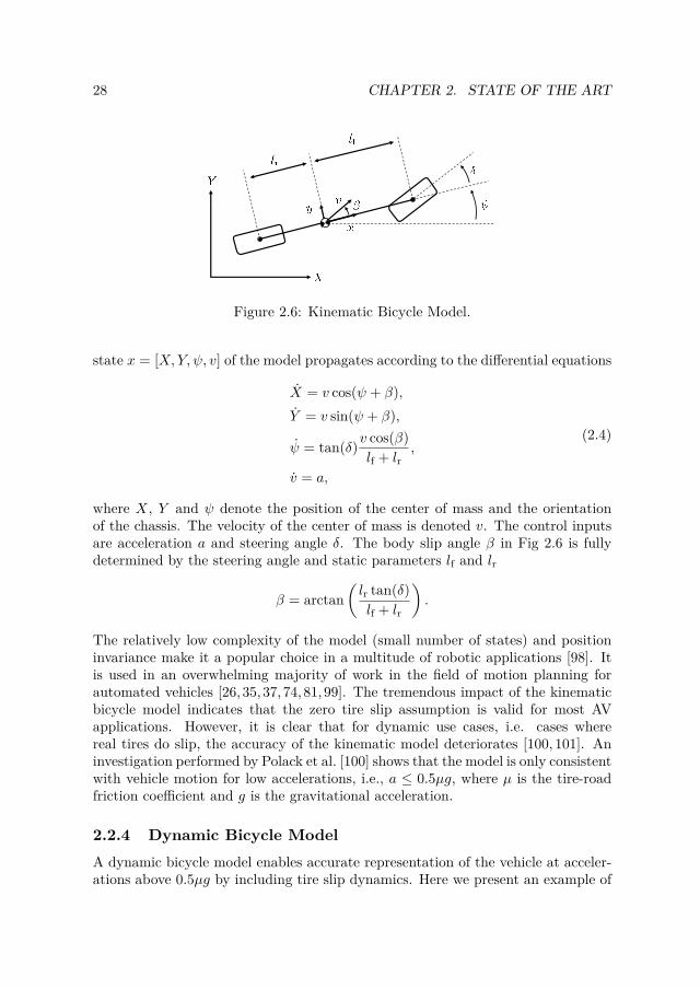
28 CHAPTER 2. STATE OF THE ART
Figure 2.6: Kinematic Bicycle Model.
state x = [X,Y, ψ, v] of the model propagates according to the differential equations
X = v cos(ψ + β),Y = v sin(ψ + β),
ψ = tan(δ)v cos(β)lf + lr
,
v = a,
(2.4)
where X, Y and ψ denote the position of the center of mass and the orientationof the chassis. The velocity of the center of mass is denoted v. The control inputsare acceleration a and steering angle δ. The body slip angle β in Fig 2.6 is fullydetermined by the steering angle and static parameters lf and lr
β = arctan(lr tan(δ)lf + lr
).
The relatively low complexity of the model (small number of states) and positioninvariance make it a popular choice in a multitude of robotic applications [98]. Itis used in an overwhelming majority of work in the field of motion planning forautomated vehicles [26, 35, 37, 74, 81, 99]. The tremendous impact of the kinematicbicycle model indicates that the zero tire slip assumption is valid for most AVapplications. However, it is clear that for dynamic use cases, i.e. cases wherereal tires do slip, the accuracy of the kinematic model deteriorates [100, 101]. Aninvestigation performed by Polack et al. [100] shows that the model is only consistentwith vehicle motion for low accelerations, i.e., a ≤ 0.5µg, where µ is the tire-roadfriction coefficient and g is the gravitational acceleration.
2.2.4 Dynamic Bicycle ModelA dynamic bicycle model enables accurate representation of the vehicle at acceler-ations above 0.5µg by including tire slip dynamics. Here we present an example of

2.2. VEHICLE DYNAMICS FOR MOTION PLANNING AND CONTROL 29
(a) Top view
(b) Side view
Figure 2.7: Dynamic bicycle model.
such a model, based on standard literature [83]. The model is derived by meansof textbook Newtonian mechanics from the forces generated between the tires andthe road. Figures 2.7a and 2.7b outline the kinematic and dynamic properties usedin the model. Given an input u = [δ, Fxf, Fxr] consisting of the steering angle andtractive force inputs at the front and rear tires, the state x = [X,Y, ψ, ψ, vx, vy]propagates as
X = vx cosψ + vy sinψ,Y = vx sinψ − vy cosψ,
ψ = 1Iz
(lfFyf − lrFyr) ,
vx = 1m
(Fxf + Fxr)− g sin θ −Rx − Faero,
vy = 1m
(Fyf + Fyr)− vxψ + g sinφ,
(2.5)

30 CHAPTER 2. STATE OF THE ART
with
Fyf = f(αf , Fxf, Fzf , µ),Fyr = f(αr, Fxr, Fzr, µ),
Fzf = 1lf + lr
(−mvxh−mgh sin θ +mglr cos θ) ,
Fzr = 1lf + lr
(mvxh+mgh sin θ +mglf cos θ) .
Just as for our example kinematic model X, Y and ψ denote the position of thecenter of mass, and orientation of the vehicle. However, contrary to the kinematicmodel, the longitudinal and lateral accelerations vx, vy and yaw acceleration ψare determined by dynamic properties (forces and inertias), rather than kinematicproperties. The lateral forces on the front and rear tires Fyf and Fyr are determinedby a tire model f(α, Fx, Fz, µ). Forces Rx and Faero represent rolling resistance andaerodynamic drag. The mass of the vehicle is denoted by m and the moment ofinertia about the z-axis is denoted by Iz. Parameters lf, lr and h specify the positionof the center of mass relative to the wheel contact patches. Angles θ and φ denotethe grade and bank angles of the road and g the gravitational acceleration. Fromthe point of view of real time motion planning and control, there are three practicalchallenges with using such a dynamic model.
First, several model parameters that have substantial impact on motion capa-bility, for example the friction coefficient µ, the normal loads Fzf , Fzr and the gradeand bank angles θ, φ, are not spatially invariant. This requires the motion plan-ning algorithm to allow a time/space-varying motion model, preventing the use ofseveral approaches, recall Section 2.1.
The second challenge is computational tractability. It is typically not possibleto accommodate the full body dynamics including tire models in real time motionplanning and control, within an acceptable replanning time. This forces the designerto introduce simplifications in the model based on assumptions related to individualapplications.
This leads us to the third practical challenge - coupled dynamics. A commonapproach to reducing computational complexity is to decouple the lateral and longi-tudinal dimensions to reduce the overall complexity of the motion planning problem.However, during aggressive maneuvering, lateral, longitudinal and yaw dynamicsare tightly coupled [97, 102]. The coupling stems from the upper bound of com-bined lateral and longitudinal force on each tire, see e.g., Fig. 2.5. This means thatoptimal utilization of available grip requires coordinated planning and control ofthe three dimensions simultaneously. Hence, simplification of the problem throughdecoupling is not an option. Nonetheless, previous works show that computationaltractability with the full dynamic bicycle model is possible through clever designchoices and state of the art motion planning algorithms [27,28].

2.2. VEHICLE DYNAMICS FOR MOTION PLANNING AND CONTROL 31
Figure 2.8: Road aligned (Frenet) coordinate frame
2.2.5 Road Aligned Coordinate Frame
For motion planning and control, the position and orientation of the vehicle relativeto the road is usually more relevant than its position and orientation in a Cartesiancoordinate system. Therefore, it is common to express the vehicle dynamics modelin a road aligned coordinate frame, sometimes referred to as a Frenet frame [98,103]. Fig. 2.8 introduces the position and orientation variables of a road alignedcoordinate frame. Here, the s coordinate denotes the progress along the lane centerand the d coordinate denotes the lateral deviation from the lane center, increasingto the left. Variables ψc and κc = ∂ψc
∂s denote the tangent angle, and curvature ofthe lane at a point on the lane center where the vehicle’s position is perpendicularto the tangent of the lane. The angle ∆ψ = ψ − ψc represents the relative anglebetween the vehicle yaw angle and the tangent angle of the lane. The time evolutionof s, d and ∆ψ is derived from geometric relations, and given by
s = vx cos (∆ψ)− vy sin (∆ψ)1− dκc
,
d = vx sin (∆ψ) + vy cos (∆ψ),
∆ψ = ψ − κcvx cos (∆ψ)− vy sin (∆ψ)
1− dκc,
This representation of position and orientation in terms of s, d and ∆ψ can be usedto replace X, Y and ψ in both the kinematic model (2.4), and the dynamic model(2.5). In the context of motion planning and control, expressing vehicle dynamics insuch a road aligned frame facilitates the encoding of desirable behaviors as costs andconstraints. For example, a desire to have the vehicle stay within lane boundaries(which is nontrival to encode using a cartesian coordinate system) can be easilyand efficiently encoded as a constraint on d.

32 CHAPTER 2. STATE OF THE ART
2.3 Analysis of Research Gaps in Related Work
The general motion planning problem formulation outlined in Chapter 2.1 can beinstantiated for a wide range of AV functionalities/features, for example highwaydriving, parking etc. The wide range of operational scenarios in which AVs aredeployed present substantial variations in the requirements and performance metricsfor motion planning and control functionality. For example, in a parking scenario,spatial precision and accurate representation of the vehicle shape are importantaspects for obtaining the desired motion behavior, while aspects like replanning rateand tire dynamics are not, due to low speeds and a relatively static environment.
In this chapter, we dive into the specifics of motion planning and control incritical situations. We outline related academic works from multiple fields, andprovide our own analysis, highlighting research gaps.
2.3.1 Differentiating Stopping Locations in Local Planning
The area of contingency motion planning in the event of faults is much less re-searched than other aspects of motion planning for automated vehicles [35]. Thefollowing proposed methods represent initial steps. Magici et al. [104] formulate afail-safe motion planning problem using optimal control, with the objective to reacha full stop, under constraints to avoid an over-approximated predicted occupancyof adjacent vehicles [105]. A version of the algorithm presented in [99] is employedto solve the resulting motion planning problem using an RTI scheme. In [106],Pek et al. extend the work in [104], by reducing computational times through de-coupling longitudinal and lateral dynamics. Furthermore, the proposed algorithmis compared with a state space sampling, trajectory rollout method, namely Wer-ling et al. [41] and show a performance increase over a range of scenarios fromthe Commonroad benchmark [107]. A notable non- optimization based example ispresented by Salvado et al. [108]. The authors propose a state lattice algorithmbased on precomputed motion primitives with the goal of finding a collision freetrajectory from an arbitrary initial state to a full stop, in the event of a fault. Thelattice based approach enables long term planning all the way to a full stop evenfrom high initial velocities.
The above examples of local motion planning methods are designed to providecollision free fallback solutions without depending on a particular goal locationbeing provided from external functionality. This provides the core safe stop func-tionality, namely to take the vehicle to a stop, without colliding with obstacles.However, the methods have several common drawbacks. First, there is no differen-tiation of stopping locations in terms of risk. Therefore, the algorithms are just aslikely to guide the vehicle to a stop in the middle of the lane as on the road shoulder,outside active lanes, which would constitute a lower risk stopping location. Second,all three methods employ a kinematic bicycle model to represent vehicle motion,which restricts the algorithms to non-dynamic motion [100]. This does not reflect

2.3. ANALYSIS OF RESEARCH GAPS IN RELATED WORK 33
the potential urgency of action in a critical situation. Next, we outline alternativesfor improved vehicle representation in critical situations.
2.3.2 Impact of Vehicle Model Accuracy At The LimitIt is intuitively clear that the planning of motions that are not dynamically feasible,e.g., going through a slippery turn at high speed, may lead to accidents. Therefore,the convention in vehicle motion control is to use conservative representations ofthe vehicle’s physical limitations [83, 109]. This is a sensible strategy for manysituations, but not necessarily for all types of critical situations. For example, in acollision avoidance situation, not being able to fully utilize all available actuationcapacity due to a conservative representation of dynamic feasibility will impair thevehicle’s capacity to avoid accidents.
This motivates research in vehicle motion planning and control at the limits ofhandling, i.e., near the adhesion limit of the tires. Accurate control in such aggres-sive maneuvers requires an internal vehicle model that to some extent captures theadhesion limit and the slip dynamics Furthermore, near the limit of tire adhesion,longitudinal, lateral and yaw dynamics are tightly coupled [97]. These propertiesmake motion planning and control at the limits of handling a challenging researchproblem.
Research in the area has seen substantial progress and increasing interest overthe last decade [96,102,110–112]. Many results have been obtained through devel-opment toward autonomous vehicle racing, which in many respects is analogous tomotion planning in critical situations. Early progress was made for single vehicleracing in static environments, i.e. without other vehicles on the road. In such a set-ting, a motion plan can be computed offline, ahead of time [113–116], reducing theonline problem to trajectory tracking at the limit of handling [96,117,118]. The in-troduction of unknown and dynamic obstacles (such as other vehicles on the road),requires that both motion planning and control have to be performed online [28,29],to be able to react promptly to updated conditions in the planning problem. Thisadds strict requirements on the computational efficiency of the motion planningalgorithm, highlighting a trade-off between the following properties:
1. Model complexity, i.e., number of states in the model (higher complexityallows higher accuracy).
2. Planning horizon length, i.e. the length of the future time window over whichto plan vehicle motions.
3. Planning time, i.e., execution time of the planning and control algorithm.
Increasing either 1 or 2 will lead to an increase in 3, and if planning time becomesexcessively long, the vehicle will be unable to react promptly to a dynamicallychanging environment.
Due to this trade-off, the field of motion planning and control at the limits ofhandling is dominated by techniques based on numerical optimization, Section 2.1.4,

34 CHAPTER 2. STATE OF THE ART
for two reasons. The primary reason is that computational load scales relativelywell with the complexity of the vehicle model, compared to alternative methods.This allows the use of a vehicle model that includes the combined lateral, longitu-dinal, yaw and slip dynamics, which in turn enables the planning of coordinatedmaneuvers that handle and exploit that these properties are tightly coupled atthe limits of handling. Such a model (e.g., the dynamic bicycle model of Section2.2.4) provides a more accurate representation of the vehicle close to the physicallimit [100,101].
The secondary reason is that solutions computed by a numerical optimizationapproach are not restricted to a discretized search space, meaning that the plannedfuture state of the vehicle is not constrained by the resolution of the search space,and can therefore find a solution that is closer to the optima. Liniger et al. [28]provide an example highlighting this, by comparing an optimization based schemewith a trajectory rollout scheme based on selection from a precomputed trajectorylibrary, both using the same dynamic vehicle model. The authors conclude thatthe purely optimization based scheme provides a lower closed loop cost, i.e., higherperformance with respect to desired behavior compared to the trajectory libraryapproach.
It is intuitively clear that accuracy in the internal vehicle model (in terms ofdynamics and dynamic limitations) of motion planning and control algorithms hasan impact on the vehicle’s capacity to avoid accidents in critical situations. How-ever, previous research work does not offer explicit experimental evaluation of towhat extent this aspect impacts accident avoidance performance in the context offull body real time motion planning and control.
2.3.3 Local Minima of the Motion Planning ProblemIt has been identified by several studies that purely optimization based approachese.g., RTI, sometimes struggle when the planning problem includes discrete decisions[26,28]. As an example, if an RTI approach were to be used in the situation depictedin Fig. 2.9, and the initial guess would be to the left of the pedestrian, then the localsolver would not be able to find any solution located to the right of the pedestrian,even if such a solution would be globally optimal with respect to the cost function.The intuition behind the phenomenon is that at each iteration the optimizationproblem is solved locally around an initial guess (for computational efficiency) andtherefore the optimizer is unlikely to find a solution in a different part of the statespace, that may contain the globally optimal solution. See Section 2.1.4 for furtherdetails on the RTI concept. Liniger et al. [28] mitigate the issue by using dynamicprogramming to select a high level corridor in which the motion planning problemis convex.
Such a solution works well in the application evaluated in [28], but for criticalsituations in general, it is non-trivial to select the right corridor. We argue that,since such a discrete decision is dependent on the vehicle’s time-varying dynamicsand dynamic limitations, it should be made at the local planning level with a high

2.3. ANALYSIS OF RESEARCH GAPS IN RELATED WORK 35
Figure 2.9: Illustration of local optima in relation to motion planning in criticalsituations. The two planned trajectories, dashed blue and solid orange, correspondto local optima of the motion planning problem, with respect to a value functionrepresenting the intended behavior. The solid orange alternative is also the globaloptimum
fidelity vehicle model, as opposed to at a higher level of abstraction with a lowerfidelity vehicle model.
2.3.4 Time-Varying Traction Limits and Tire DynamicsIn Section 2.3.2 we concluded that real time motion planning and control at thelimits of tire adhesion is non-trivial to achieve. To further complicate matters, realtire force limits and tire dynamics are not static. Instead, they vary with road/tireconditions and normal load on the tire. Accurately capturing this phenomenon inthe context of online motion planning and control is an active research area withstrong implications on accident mitigation performance in critical situations.
Several previous works suggest to model the physical limitations of a vehicle interms of traction by imposing constraints on longitudinal and lateral acceleration.Lima et al. [81], uses a kinematic model under polytopic acceleration constraintsderived from the the g-g diagram [119]. The polytopic constraint representation ispermissive in terms of design, but near the limit of adhesion (i.e., when the con-straints are active) the kinematic model does not provide an accurate representationof the dynamics of the vehicle [100].
Recent work by Subosits et al. [29] proposes a computationally efficient methodbased on an oriented point mass model expressed in a road aligned frame. Thetraction limit of the vehicle is represented by an elliptic constraint on lateral andlongitudinal accelerations derived from the friction ellipse and predicted normalload. The approach is able to capture the effects of local traction variations androad topography, and the oriented point mass model does not deteriorate in terms ofaccuracy at high accelerations. The approach is successfully evaluated in a collisionavoidance scenario with a full scale test vehicle. Fors et al. [120] use a similarmodeling approach for coordinating between braking and steering in critical evasive

36 CHAPTER 2. STATE OF THE ART
maneuvers.A common element among these methods is that the tire force traction bound-
ary is represented as limits on acceleration at the center of mass. Granted, theexperimental evaluation of [29] makes clear that such a method captures the dom-inating physical factors at play, but it remains unclear whether even better resultsin terms of traction utilization can be obtained by avoiding this simplification.Furthermore, [29] and [120] uses the friction ellipse as a basis for deriving tractionconstraints. According to Brach et al [95], this is can be an overly conservativerepresentation in some cases.
Alsterda et al. [121] present an alternative approach to the problem of time-varying traction. An optimization based approach, extending on Brown et al. [122],is used for planning lateral motion withmultiple models of the dynamics. A nominaland a contingency plan are produced in parallel, where the latter assumes a lowervalue of the tire-road friction coefficient µ, and associated tire model. The approachis validated in simulation for a class of critical situations characterized by rapidtraction reduction in a corner. Results show that the method is able to adaptvehicle motion to time-varying traction conditions. Similar contingency planningapproaches are presented in [123,124].
Yet another approach to tackling the problem of time/spatial variations of ve-hicle dynamics is to employ tools from machine learning. Spielberg et al. [125]highlight the capacity of neural networks to encode a time-varying vehicle model.The network is trained on data collected on multiple road surfaces and deployedin a feedforward-feedback control scheme for path tracking. The neural networkscheme outperforms a baseline physics based scheme, particularly where tractionconditions vary. For the combined motion planning and control problem, Hewinget al. [126, 127] propose an approach where the dynamics are modeled as a sumof a dynamic bicycle model with nonlinear tire models (simplified Magic Formula)and a Gaussian Process (GP) [128]. The latter is intended to capture residual spa-tially varying dynamics. The approach was subsequently validated on a full scaletest vehicle with impressive racing results [27]. Rosolia et al. [129, 130] proposeanother data-driven approach that leverages theory from model predictive controlto guarantee recursive feasibility and non decreasing performance between each lap.These results validate that combining traditional modeling techniques with data-based online adaptation is an efficient and safe way to adapt the planned motionwith respect to local variations in vehicle dynamics.
However, to perform such adaptive motion planning and control, one needs toestimate these changes to the dynamics ahead of the vehicle. The listed machinelearning based approaches for combined motion planning and control [27, 126, 127,129,130] are tailored to racing on closed circuits and build on the assumption thateach position on the track is visited multiple times. Data from previous visits toa certain part of the track is used to update dynamics at that particular position,such that in the next lap, local dynamics can be estimated ahead of the vehicle.For an AV deployed in regular traffic, this is not a viable method for obtaining thisdata, because the AV may not have visited the area recently, hence reliable data

2.3. ANALYSIS OF RESEARCH GAPS IN RELATED WORK 37
Figure 2.10: Example of road surface classification from forward looking camera.Here, the road surface classes are dry (a), wet (b), snow (c) and gravel (d). Figureincluded from [132] with permission of the authors.
is unavailable. Thus, the iterative learning approach is generally not applicable tocritical situations.
2.3.5 Impact of Friction Estimation PerformanceFortunately, there are other ways to estimate dynamics and dynamic limitationsahead of the vehicle. State of the art techniques for friction estimation are outlinede.g., in [131]. From a motion planning perspective, there are two distinct categoriesof friction estimation algorithms, namely those that provide a local estimate at thevehicle footprint, and those that provide a predictive estimate ahead of the vehicle.
Local friction estimation techniques [133,134] use vehicle dynamics models, anddata from on-board sensors to estimate the friction coefficient. Such methods havehigh accuracy but the estimate is only available at the vehicle footprint (as opposedto ahead of the vehicle) and in the presence of tire slip [135]
Predictive friction estimation techniques on the other hand use a forward look-ing sensor to estimate the friction coefficient ahead of the vehicle. Recent ad-vances in supervised machine learning and computer vision have greatly improvedperformance of such functionality, mainly through road surface classification fromforward looking camera images [132, 136, 137], providing a predictive estimate on-line at high availability. Fig. 2.10 provides a visualized example of the functionality.However, a drawback of this approach is that only a small number of road surfaceclasses are visually distinguishable (e.g., dry, wet, snow/ice), and therefore the res-olution is poor compared to state of the art local friction estimation methods. Tothe best of our knowledge, the implications of performance limitations in state ofthe art local and predictive friction estimations have not been evaluated in the

38 CHAPTER 2. STATE OF THE ART
context of traction adaptive motion planning and control.
2.3.6 SummaryTo summarize this chapter, we have identified five distinct research gaps in thefield of motion planning and control in critical situations (one for each precedingsubsection):
i. In the case of internal faults or performance limitations, it is beneficial todetermine the stopping position at the local planning level, but it is unclearhow to represent risk levels of different stopping locations at this level ofabstraction.
ii. Over-estimation and under-utilization of the vehicle’s dynamic capabilitiesmay impair the vehicle’s capacity to avoid accident in critical situations. How-ever, this has not been previously studied in the context of full body motionplanning and control in full scale experiments.
iii. Optimization based motion planning schemes are well suited to the com-putational trade-off associated with motion planning and control in criticalsituations, but it is unclear how to handle the problem of local minima in thevalue function.
iv. It has been recognized that vehicle dynamics and dynamic limitations arenon-static and can vary along the prediction horizon, but it remains unclearhow to represent such time-variations accurately and efficiently in the contextof motion planning and control, and how to anticipate future changes fromsensor data.
v. It has been recognized that state of the art local and predictive friction esti-mation techniques have limited performance in terms of accuracy, availabilityand foresight, but the implications of this when applied to motion planningand control in critical situations have not been previously evaluated.
This thesis is intended as a step towards addressing the identified gaps. Specifically,Paper A is aimed at research gap i., Papers B and C are aimed at research gapsii., iii., iv., and Paper D is aimed at research gap v. In terms of the categoriesof critical situations introduced in Section 1.2.2, all the identified research gapshave some impact on all three categories. However, there are particularly strongimplications for gap i. in situations with internal system faults or performancelimitations, gaps ii., iv. and v. on situations with rapid changes in operationalconditions, and gaps ii. and iii. in situations with unsafe behavior from otherroad users. Relationships between appended papers and key parts of the thesis,including identified research gaps, are summarized in Table 1.2.

Chapter 3
Summary of Contributions
This chapter summarizes the research contributions of the thesis, starting with thehigh level contributions of characterizing the motion planning and control problemin reference to state of the art motion planning algorithms, followed by a briefsummary of our suggested approach. Thereafter follows individual summaries ofeach of the appended papers.
3.1 Characteristics of Motion Planning and Control inCritical Situations
This thesis and the appended papers Papers A through D represent a sequentiallearning process in which a list of characteristics of the motion planning and controlproblem in critical situations was gradually built up, along with knowledge aboutsuitable solution algorithms. At this stage of the research work, we have arrived atthe following characterization:
1. Accuracy of Vehicle Model at the Limit: The vehicle model needs toaccurately represent dynamics and dynamic limitations for maneuvers closeto the physical limit.
2. Time-varying Vehicle Model at the Limit: The vehicle model needs toaccount for variations in vehicle dynamics and dynamic limitations.
3. Foresight in Terms of Motion Capability: Changes in dynamics anddynamic limitations, e.g., due to local traction changes must be anticipatedahead of the vehicle.
4. Sufficiently Long Planning Horizon: A sufficiently long planning horizon(at least 3-5s depending on the scenario) is required to handle the inertia andlimited actuation capacity of the vehicle.
39

40 CHAPTER 3. SUMMARY OF CONTRIBUTIONS
5. Sufficiently Short Planning Time: A short computation time of the algo-rithm (ts < 100ms) is required in order to react promptly to sudden changesin the traffic scene.
6. Discrete Decision Making: When faced with a discrete decision, e.g., toswerve left or right of a suddenly appearing obstacle, the planner should selectthe lowest cost reachable option, i.e., avoid getting stuck in local minima.
7. Risk Levels of Stopping Locations: If planning to a full stop, differentia-tion between stopping locations in terms of risk levels needs to be done at thelocal planning level, in order to make a complete risk assessment of differentmaneuver alternatives.
8. Severity Minimization: If the accident is unavoidable, the goal of motionplanning and control should be to utilize the full physical capacity of thevehicle to minimize the severity of the accident.
These characteristics should be collectively considered in the design of motion plan-ning and control functionality for critical situations. Next, we outline our take onalgorithm design.
3.2 Proposed Algorithm Design and Implementation
To be able to perform experimental evaluation for the research work, a motionplanning and control framework was incrementally developed with the aim to ac-commodate all of the identified characteristics. In its current form, the frameworkrealizes characteristics 1 through 7, while integration of the work on characteristic8, severity minimization1, is left for future efforts. A discussion and motivation ofindividual design choices is found in Section 4.1.1.
The framework includes elements from all the algorithms described in PapersA through D. The latest software instantiation of the framework is implementedas a ROS network [138], i.e., a set of software nodes written in C++/CUDA andPython, executing concurrently on multicore CPU and GPU. ROS is used to fa-cilitate integration of the planning and control stack with experimental platformsand simulators. For example, in preparing for the field tests of Paper C, parallelROS-integrations with the test vehicle software stack OpenDLV2, and our simula-tion environment based on [139,140], enabled seamless switching between real andsimulated test vehicle, which accelerated development substantially.
The proposed framework encompasses characteristics 1 through 7 in the fol-lowing ways: The framework uses a dynamic bicycle model with tire force inputsexpressed in a road aligned frame (see Appendix B of Paper C for a detailed account
1Work in collaboration with Parseh et al. on motion planning and control when facing un-avoidable collision, mentioned in Section 1.2.2
2Cf. https://github.com/chalmers-revere/opendlv

3.3. SUMMARY AND CONTRIBUTIONS OF INDIVIDUAL PAPERS 41
of the model), which allows representation of time-varying tire force limits and tiredynamics at an admissible computational cost. This way, we achieve sufficientlyaccurate vehicle representation in the algorithm to allow high traction utilizationin the presence of time-varying actuation capability (characteristics 1,2). The opti-mization procedure of the algorithm is based on a state of the art RTI solver frame-work, [66,67,71], which enables a favorable computational trade-off between modelcomplexity, horizon length and computation time (characteristics 1, 4 and 5). Dis-crete decisions (characteristic 6) and infeasibility issues arising from time-varyinginput constraints are jointly handled by introducing a sampling augmentation pro-cedure (see Papers B, C). The GPU-accelerated procedure uses forward simulationof the dynamic bicycle model under an LQR controller to produce dynamicallyfeasible candidate trajectories throughout the drivable area. Selection among theset of candidates (including the forward shifted solution from the previous planningiteration), based on a cost function that is shared with the optimization procedure,effectively handles discrete decisions in the planning problem. Since all trajectoriesin the set are dynamically feasible by construction, local decision making will alsotake locally varying traction into account. In addition, this feature of the samplingaugmentation procedure ensures the availability of a feasible initial guess for theoptimization procedure, even at rapid changes to the constraint situation, due toe.g., an obstacle popping up, or a rapid traction reduction. Sufficient accuracy,availability and foresight of dynamics and dynamic limitations (characteristic 3)are obtained by fusing local and predictive (camera based) friction estimates usingheteroscedastic gaussian process regression, as per the procedure described in Pa-per D. The risk level of stopping locations is encoded as a cost on the final state(characteristic 7). The current implementation achieves a worst case planning time(including both sampling augmentation and optimization) around 100ms with theabove mentioned vehicle model, and a prediction horizon of 4s on standard com-pute hardware (a PC with an Intel Core i7-7820HK CPU @ 2.9 GHz and an NvidiaGeForce GTX 1070 GPU).
3.3 Summary and Contributions of Individual Papers
This section summarizes each of the appended papers individually. Recall Table 1.2for an overview of how research questions, identified research gaps and contributionsmap to individual papers.
3.3.1 Paper A
L. Svensson, L. Masson, N. Mohan, E. Ward, A. Pernestål Brenden, L. Feng,M. Törngren, ”Safe Stop Trajectory Planning for Highly Automated Vehicles:An Optimal Control Problem Formulation” 2018 IEEE Intelligent VehiclesSymposium (IV), pp. 517-522, Changshu, China.

42 CHAPTER 3. SUMMARY OF CONTRIBUTIONS
This paper concerns the motion planning problem for safe stop maneuvers, i.e.,the planning of maneuvers that take the vehicle to the safest reachable stoppinglocation (realizing a minimum risk condition as per the J3016 definition [4]) upona hazardous event. With a safety supervisor system architecture as a basis [22], weformulate the safe stop motion planning problem as an optimal control problem,without a predefined stopping location. Instead, risk levels of candidate stoppinglocations are included in the cost function. Furthermore, we propose a trajec-tory library planning algorithm to solve the problem in real time. The method isvalidated by comparison to a globally optimal solution computed using dynamicprogramming and through simulation 3.
The primary contribution (a) of the paper lies in the formulation of the safestop motion planning problem. With our formulation, the decision on where tostop is made at the local planning level in conjunction with vehicle dynamics andcollision avoidance constraints - as opposed to pre-selecting a stopping locationat the decision making layer which is subsequently passed to local planning. Intheory, solving the problem enables optimal utilization of the vehicle’s physicalcapacity to avoid accidents in critical situations. This is how we propose to tackleresearch gap i., introduced in Section 2.3. However, solving such a problem overa sufficiently long prediction horizon, under real time computational constraints,with an accurate vehicle model is a difficult task towards which we directed ourfurther research efforts, namely Papers B and C. The secondary contribution (b)is the proposal and development of a trajectory library based planner, as well asits validation, showing that it can solve the problem for simple critical scenarios,i.e., situations with internal faults without immediate impact on perception oractuation capability. The trajectory library approach was selected in order to allowlater extension to using the dynamic rather than the kinematic bicycle model, andthereby be able to plan motions up to the limit of handling. We later pivoted awayfrom the trajectory library concept in favor of an optimization based approach,after arriving at the conclusion that the position invariance assumption, which isfundamental for the trajectory library concept, is quite restrictive for maneuvers atthe handling limit because of the strong influence of local traction conditions. Thethird contribution (c) of the paper is the preliminary evaluation of the concept inwhich we show that the approach generates desired behavior in a particular typeof critical situation.
Author’s contribution: The author of this thesis is responsible for developingthe idea in collaboration with Lola Masson, Naveen Mohan and Martin Törngren,further developing the mathematical problem formulation together with Lei Fengand implementing the method as part of a ROS framework together with ErikWard, as well as authoring the paper. All co-authors provided feedback on thepaper drafts.
3Though not included in the paper, a real time capable implementation of the algorithm waslater produced, and the algorithm was further validated using the KTH Research Concept Vehicleas a test platform. Parts of the experimental results were presented in [30]

3.3. SUMMARY AND CONTRIBUTIONS OF INDIVIDUAL PAPERS 43
3.3.2 Paper B
L. Svensson, M. Bujarbaruah, N. R. Kapania and M. Törngren, ”Adap-tive Trajectory Planning and Optimization at Limits of Handling”, 2019IEEE/RSJ International Conference on Intelligent Robots and Systems (IROS),pp. 3942-3948, Macau, China.
This work tackles the problem of motion planning at the limits of handling, in thepresence of locally varying traction conditions, to be employed in critical situations.The problem formulation considers that the physical limitations of a vehicle aresubject to local variation, for example in terms of traction. To capture this property,we formulate an optimal control problem with a force-input dynamic vehicle model,under time-varying input constraints. This is how we propose to tackle research gapiv., Section 2.3. Furthermore, we propose a real-time capable solution method basedon a combination of trajectory rollout and quadratic programming. Through anextensive simulation study, we show that the proposed adaptive method increasesthe vehicle’s ability to avoid collision in critical scenarios, when compared to anon-adaptive approach.
The first contribution (d) of this paper is a novel problem formulation for trac-tion adaptive motion planning and control. The formulation is based on a force-input vehicle model paired with time-varying input constraints that represent thevehicle’s time varying tractive force envelope. The approach is a practically viableway to achieve full utilization of the vehicle’s locally varying physical capacity toreduce accident risk in critical situations. The second contribution (e) is the realtime capable 4 solution method that combines trajectory rollout and optimizationbased motion planning. Integrating trajectory rollout in the RTI scheme mitigatestwo separate issues of a purely optimization based approach: First, the trajectoryrollout procedure provides a dynamically feasible initial guess to the optimization,even in the case when the solution from the previous timestep has become infea-sible due to the time-varying constraints. Second, it mitigates the sensitivity tolocal minima and allows discrete decision making by evaluating sampled optionsthroughout the drivable area. This is how we propose to tackle research gap iii.,Section 2.3.
Author’s contribution: The author produced the original idea, in terms of theproblem formulation and the proposed solution method, developed algorithmic as-pects in collaboration with Monimoy Bujarbaruah and vehicle dynamics modelingaspects based on discussions with Nitin Kapania, and authored the paper. MonimoyBujarbaruah contributed substantially to all sections of the paper. All co-authorsprovided feedback on the paper drafts.
4Design choices for the algorithm were made to enable real time execution with a state of theart implementation. However, the preliminary implementation that was used for the simulationstudy was not real time capable.

44 CHAPTER 3. SUMMARY OF CONTRIBUTIONS
3.3.3 Paper CL. Svensson, M. Bujarbaruah, A. Karsolia, C. Berger and M. Törngren, ”Trac-tion Adaptive Motion Planning and Control at the Limits of Handling”, sub-mitted for possible journal publication, 2020.
This paper is an extension of Paper B and represents a substantial amount of de-velopment work with the goal to refine the traction adaptive motion planning andcontrol concept to a point where it could be experimentally evaluated in a real-istic setting. Extensions of the algorithmic framework include replacement of thequartic/quintic polynomials in the trajectory rollout step with GPU acceleratedforward simulation of the model under a Linear Quadratic Regulator (LQR) andextension of the force input vehicle model to include pitch dynamics. Also, toenable real experiments on a test vehicle, a state of the art C++/CUDA imple-mentation of the algorithm was produced, as well as a low level control interfacethat translates the force commands from the planner/controller to vehicle controlsin terms of steering and acceleration/brake. We proceed with experimentally eval-uating the planner in four example critical scenarios and conclude that tractionadaptive motion planning and control improves the capacity to avoid accident inall tested critical scenarios, compared to an equivalent scheme with static tire forceconstraints. The experimental evaluation of the method tackles research gap ii.,Section 2.3.
The first contribution (g) of this paper is the extensive experimental evaluationof traction adaptive motion planning and control. The evaluation was performedduring a total of 7 vehicle test days at two different test tracks. In comparison withPaper B, this evaluation provides much stronger justification that the conclusionshold for real world conditions. The second contribution (f) is that we show thatthe proposed algorithmic concept of sampling augmented adaptive RTI is capa-ble of solving optimal control problems with time-varying input constraints, stateconstraints and dynamics, while avoiding local minima, in real time (ts < 100ms)over a long (4s) prediction horizon on regular PC hardware. This makes the algo-rithm especially suitable for the challenging problem of motion planning in criticalsituations, as well as many other applications in robotics.
Author’s contribution: The author produced the original idea, further developedalgorithmic and vehicle dynamics aspects, produced the implementation, integratedthe algorithm on the experimental platform, planned, organized and executed theexperiments in collaboration with Arpit Karsolia and Christian Berger, and au-thored the paper. Monimoy Bujarbaruah contributed substantially to all sectionsof the paper. All co-authors provided feedback on the paper drafts.
3.3.4 Paper DL. Svensson and M. Törngren, ”Fusion of Heterogeneous Friction Estimatesfor Traction Adaptive Motion Planning and Control”, submitted for possibleconference publication, 2021.

3.3. SUMMARY AND CONTRIBUTIONS OF INDIVIDUAL PAPERS 45
The experimental work on Paper C highlighted that the traction adaptive motionplanning concept is sensitive to the accuracy in the predictive friction estimate.Both over-estimation and under-estimation may lead to suboptimal performancein terms of avoiding accidents in critical situations. This motivated an investiga-tion of how realistic performance of state of the art friction estimation techniqueswould impact accident avoidance performance. In a simulated environment, weemulate three different realistic friction estimation techniques based on state of theart techniques and evaluate performance by comparing with a planner/controllerprovided with ground truth friction. The first configuration emulates a local fric-tion estimation method of high accuracy, but where the estimate is only availablelocally at the vehicle footprint, and at tire force utilization above 0.5. The secondconfiguration emulates a camera based method that provides a high availabilitypredictive estimate over the whole prediction horizon, but has lower accuracy. Thethird configuration is our proposed fusion approach, that merges estimates fromthe first and second configurations, while preserving estimation uncertainty, usingheteroscedastic GP regression. We show that for the two evaluated critical scenar-ios, the fused estimate performs on par with ground truth, while the two individualfriction estimate configurations underperform in either of the two critical scenarios.It is the aim of the simulation based evaluation to tackle research gap v., Section2.3.
The first contribution (h) of this paper is highlighting that individual paradigmsof state of the art friction estimation algorithms (i.e., local or camera based) areinsufficient for satisfactory traction adaptive motion planning and control in criti-cal situations. However, fusion of estimates from multiple paradigms can providea sufficient accuracy, availability and foresight, to generate near optimal motionbehavior. This further supports the external validity of the conclusions of PapersC, D. The second contribution (i) is the proposed fusion concept that produces apredictive estimate that is conservative with respect to input data with associatedheterogeneous uncertainties. The fused estimate is conservative in the sense thatprobability of over-estimation is low, while not being overly conservative, such thatcollision avoidance performance deteriorates.
Author’s contribution: The author produced the original idea, developed thealgorithm, produced the implementation, integrated the algorithm with existingframework for traction adaptive motion planning and control and authored the pa-per. Martin Törngren contributed in discussions throughout the work and providedfeedback on the paper drafts.


Chapter 4
Discussion and ConcludingRemarks
This section concludes the thesis with a discussion on algorithm design choicesand on the validity of the performed experiments, followed by a brief summary ofconclusions in relation to the research questions and recommendations for futureresearch directions.
4.1 Discussion
First, we present and motivate some of the design choices made for the proposedframework for motion planning and control in critical situations. Thereafter wediscuss the validity of the performed experiments first in terms of the similarityof our experimental setup and the research target, followed by specifics on ourapproach to emulation/implementation and the measures taken to handle non-determinism in the AV perception and control system.
4.1.1 Algorithm Design ChoicesFrom the analysis of related work of Section 2.3, it is clear that optimization basedmethods, Section 2.1.4, currently outperform most other methods in terms of thecentral trade-off between model complexity, horizon length and computation time.For time invariant dynamics and dynamic limitations it is possible to achieve similarperformance in this regard with trajectory roll-out methods based on precomputedtrajectory libraries (used e.g. in Paper A). However, since each trajectory set iscomputed offline with respect to static operational conditions, the library wouldsoon grow intractably large if one were to consider time-varying dynamics anddynamic limitations, characteristic 2. In contrast, in an optimization based frame-work, such adaptation can be encoded as time-varying constraints, with potentiallynegligible addition to computational cost. However, this introduces a new problem
47

48 CHAPTER 4. DISCUSSION AND CONCLUDING REMARKS
−1 0 1 2 3 4 5
t (s)
25
50
75
100
com
pti
mes
(ms)
TA SA TA Opt TA Tot NA Tot
Figure 4.1: Computation times for motion planning and control in a collision avoid-ance scenario from the field experiments of Paper C. Total time for the tractionadaptive configuration (TA Tot) is split into fractions associated with the samplingaugmentation procedure (TA SA) and optimization (TA Opt). This is comparedagainst a purely optimization based, non-adaptive scheme (NA Tot).
in terms of the feasibility of the optimization problem. There are well establishedworkarounds for such problems, e.g., softening of the constraints by introducingslack variables [28,73]. However, this instead introduces further sensitivity to localminima in the value function. This drawback of optimization based methods haveadditional negative implications with respect to the characteristics of critical situ-ations, e.g., with respect to discrete decision making. This is elaborated in Section2.1.4. These particular shortcomings are not present in trajectory roll-out methods,indicating that the methods are to some extent complementary with respect to thecharacteristics of critical situation, which suggests an opportunity for meaningfulcombination of the two concepts. The sampling augmentation concept, describedand evaluated in Papers B, C, represents one example of such a combination, whichefficiently alleviates the feasibility and discrete decision making problems of opti-mization based approaches.
The sampling augmentation procedure is executed at the beginning of each it-eration of the motion planning and control algorithm, therefore the average compu-tation time is increased. However, at rapid changes to the constraint configuration(e.g., at traction reduction or sudden obstacle appearance), the sampling augmen-tation procedure significantly simplifies the subsequent optimization procedure byproviding it with a feasible initial guess, thereby reducing optimization time. Thisreduces worst case computation time of the whole planning algorithm. Fig. 4.1shows recorded computation times for a collision avoidance run during the field ex-periments of Paper C. At the critical points in the maneuver, where reaction timehas the largest impact on the outcome (e.g., at the first planning iteration followingobstacle appearance, t = 0.1s in Fig. 4.1), sampling augmentation does not increaseplanning time compared to a purely optimization based scheme.
The execution time of the algorithm is a major contributor to the reaction timeof the vehicle in critical situations. If the sum of computation time for object detec-
4.1. DISCUSSION 49
tion/localization and planning of the evasive maneuver is high, collision avoidanceperformance will be severely reduced due to a slow time to react. Related workstypically present a planning time in the interval 20-200 ms [28,29,41,141]. Becausereaction time was not explicitly included in the research scope of our work, a designtarget of a maximum planning time of 100 ms was selected for the development ofour framework. The underlying rationale was to select a target that was comparableto the state of the art, while being practically viable with the desired complexity ofvehicle model, and time horizon. A substantial amount of development work wasinvested to accommodate all steps of the algorithm within this target computationtime on the available hardware. Faster is always better when it comes to reactiontime. Whether or not 100 ms is a suitable design target for this application issubject to further discussion, which we return to in Section 4.3.
It is evident from the results and conclusions of papers B, C and D that movingfrom an inaccurate local vehicle model (i.e. one that does not accurately repre-sent the vehicle near the handling limit at all, or one that does not vary alongwith the time-varying dynamics and dynamic limitations of the real vehicle, orboth) to a reasonably accurate one, will drastically improve the level of utilizationof the vehicle’s capabilities, and in turn its risk reduction performance in criticalsituations. This raises the question whether an even more accurate model wouldimprove utilization even further? Recent works deploying machine learning tech-niques to capture and compensate model error online suggest that very accuratevehicle models (and consequently very high traction utilizations) can be obtainedby iteratively learning spatially varying dynamics and dynamic limitations [27,130].However, it remains unclear how such models should make predictions of dynam-ics and dynamic limitations ahead of the vehicle, for positions it has not recentlyvisited, recall Section 2.3.4.
To acheive this, we have opted for an approach where a single key parame-ter, namely the friction coefficient µ is identified online, ahead of the vehicle, fromstandard sensor data streams (forward looking camera and inertial sensors). Fromthere we derive changes to our vehicle model from first principle mechanics model-ing. This comparatively simple, physics based vehicle model is far from perfectlyaccurate, but given an accurate friction estimate, it is relatively accurate for a widerange of road conditions. For example, the dynamics model includes a linearizedMagic Formula tire model that varies in slope based on the identified friction coef-ficient. Using this simple tire model strongly contributes to the computational effi-ciency of the algorithm. The model fares well in capturing the dominating changesto tire dynamics on different surfaces, but loses accuracy as the tire force curvetapers off close to the maximum force utilization. Instead of introducing a moreelaborate tire model (that would most likely increase computation time) we counterthis by introducing a force utilization factor λ when setting the time-varying tireforce constraints. This allows us to limit the force utilization, typically to around90% of the theoretical maximum, keeping it inside an interval for which the time-varying linear tire model is acceptably accurate. This is highlighted in Figure 11of Appendix C of Paper C.

50 CHAPTER 4. DISCUSSION AND CONCLUDING REMARKS
This concept is indicative of a guiding principle we employed in designing theframework: We argue that for motion planning and control in critical situations, asystem that reliably realizes a high force utilization, e.g. ∼ 90%, on a wide rangeof road surfaces, is preferable to a system that obtains more than 90% utilizationon a particular, limited set of road surfaces while obtaining less than 90% on oth-ers. That being said, the current version of the framework does have room forimprovement in terms of for example tire modeling. We revisit this in Section 4.3.
4.1.2 ValidityIn this section we discuss the challenges to internal and external validity encoun-tered during the performed experimental and simulation studies, and the methodsused to address them. Recall Section 1.2.3, for a description of the adopted researchmethodology.
Generalization to Research Target
The research target for this work has been a production grade level 4+ AV deployedin real traffic, being exposed to various critical situations. To represent the target,we performed tests on a full scale heavy duty vehicle, Fig. 1.3b, on closed test tracksfor Paper C, and simulated test vehicles and environments for Papers A, B and D.
We argue that our experimental results obtained with a heavy duty vehicle gen-eralize well to any other front wheel steered, four wheeled 1 road vehicle, e.g., astandard passenger vehicle. The vehicle model used in the framework is parame-terized according to the test vehicle’s physical properties, e.g., its mass, moment ofinertia, length, width, position of the center of mass etc. The framework will planvery different motions for different vehicles and road surface conditions, but thevirtues of the approach, i.e., dynamic feasibility of planned motions, even at poorlocal traction conditions and a high utilization of available tire force (90% for thetests in Paper C) is independent of the vehicle type as long as the model parametersare set in accordance with the real vehicle. Effects that are more pronounced witha light vehicle such as normal force variations due to high accelerations are alsorepresented in the framework. Tests on other vehicle types have been performed insimulation with good results, but have not been included in terms of results in thethesis. The road surfaces that were used for testing at the Asta Zero 2 and StoraHolm 3 test tracks have been professionally developed to replicate realistic condi-tions, representing dry/wet asphalt and snow/ice, for vehicle testing and drivingeducation purposes. All in all, we argue that our test setup is representative of theresearch target, and our experiments therefore have strong external validity.
1The test vehicle used for Paper C has 6 wheels, but the rear axle was lifted throughout theexperiments.
2https://www.astazero.com/3https://www.storaholm.se/

4.1. DISCUSSION 51
Due to time and resource constraints, Papers A, B, D have simulation basedevaluation instead of experiments. As mentioned in Section 1.2.3 external validityof simulation based evaluation hinges on whether the simulation environment isrepresentative of the target. However, this only needs to hold for factors that arerelevant to the outcome of the experiment. By making justified design choices forthe simulation environment, a relatively strong argument can be made in regard tothe validity of simulation results as well. Two branches of simulation environmentswith different purposes have been developed during the course of this research work.
• Simplistic MATLAB based simulators for preliminary evaluation of novel con-cepts
• ROS/Gazebo-based [138, 139] simulators with similar software interfaces asthe test vehicles.
The first category was primarily used in Papers A and B, as development andevaluation tools that could be realized comparatively quickly at a point in timewhere no useful test infrastructure had yet been built up. In the evaluation forPaper A, where the focus is the inclusion of stopping locations in local planning,the motion planning algorithm is designed to generate low acceleration, smoothmotions. For such motions, a kinematic vehicle model accurately describes vehiclemotion [100, 101]. This allowed the use of a simple custom developed simulationenvironment based on the kinematic model for the initial evaluation. Paper B onthe other hand considers aggressive evasive maneuvers, which disqualified contin-ued use of the kinematic model for evaluation. Instead, we modified the simulatorby introducing a dynamic model with tire force inputs. The focus of Paper Bwas on motion planning with respect to time-varying traction limits rather thanhow to realize those maximum forces in terms of slip angles and ratios. Therefore,by introducing the assumption that commanded tire forces would be realized ifthey were inside a permitted boundary determined by the road condition and asimple tire model (friction ellipse), we could greatly simplify the vehicle model inthe simulation. This simple setup allowed us to further develop the method anddraw initial conclusions on what behavior the motion planner would generate. Themotion planning framework was later extended with a control interface, describedin detail in Appendix C of Paper C, that translates tire force commands into theacceleration and steering angle commands of the test vehicle. This solution wasexperimentally validated, strengthening the external validity of both Papers B andC. The second branch of simulators was developed with the primary purpose offacilitating preparations for field experiments. Paper A showcases an embryo of aROS/Gazebo-based simulator based on [142] intended to have the same interfacesfor commands and state information as the real test vehicle. This environment waslater replaced by one based on the FSSIM environment [140], which was continu-ously developed throughout the project. Preparatory vehicle tests for Paper C wereperformed over a period of several months, where development using simulation,live test and replay of sensor data logs was done interchangeably. During this time,

52 CHAPTER 4. DISCUSSION AND CONCLUDING REMARKS
the simulator was further tuned to mimic the behavior of the real vehicle more andmore accurately on all tested surfaces. This was later exploited in the evaluationof Paper D. We argue that at the time of the evaluation of Paper D, the simulatorwas an accurate representation of the test vehicle, which in turn was an accuraterepresentation of the research target. Therefore, we argue that also the study inPaper D has strong externally validity.
In terms of further generalization of results, we note that although the targetfor this research has been a level 4+ vehicle, many of the results generalize equallywell to driver assistance at lower levels of automation, for example in advancedADAS systems. Traction adaptive motion planning and control (Papers B, C), orpredictive friction estimation (Paper D) are just as relevant in such applications,with strong potential for improving safety of road users in the short term.
Implementation versus Emulation
In terms of dealing with the dependency on perception functionality, the implemen-tation approach described in Section 1.2.3 was initially selected. For example, in theexperimental evaluation following Paper A, the localization and state estimation ofthe test vehicle were performed through scan matching [143, 144] in a prerecorded3D lidar map - a localization technique similar that is commonly used in produc-tion grade AVs [13]. During these experiments we learned that by the time we hadfine-tuned the localization and state estimation functionality, its performance couldhave been easily emulated using differential GNSS and IMU, with no apparent ef-fect on motion planning functionality. In subsequent experiments, we generalizedthis principle of practically grounded emulation to other perception functionality,e.g., object detection and friction estimation.
Object detection was emulated in the field experiments of Paper C. We consid-ered sensor limitations in terms of detection range and occlusions by having virtualobstacles appear suddenly in front of the vehicle. This emulates realistic sensordata in a situation where an obstacle is temporally occluded or for some reason orother, difficult to detect up to a certain point in time. After an object had beendetected we assumed perfect tracking of the object so as not to introduce additionalstochasticity and therefore maintain experimental control.
In the simulation based evaluation for Paper D, two friction estimation func-tionalities were emulated. The first was a local estimate, emulated in terms of itsavailability at tire force utilizations above 50%, and its margin of error with respectto a simulated ground truth value. The second was a predictive estimate, emulatedby providing a road surface class associated with a simulated ground truth value.The emulation replicates the output of the friction estimation algorithms at a highlevel of abstraction, but captures the fundamental properties of the two differentparadigms in terms of accuracy, availability and foresight, such that we could eval-uate motion planning and control functionality e.g., based on only local frictionestimates, only predictive estimates, or fusion of the two.

4.2. CONCLUSIONS 53
This principle of justified emulation of selected perception functionality, groundedin the state of the art and practical experience enabled time-efficient (well, reason-ably time-efficient) field experiments on novel motion planning and control conceptswithout loss of internal or external validity of the performed experiments. It shouldbe noted however, that whether or not justified emulation can be applied is stronglydependent on the type of experiment to be performed.
Non-determinism
A software control system as complex as an AV, even with selected parts of itsfunctionality emulated, is always to some extent non-deterministic. Contribut-ing factors for our system include noisy sensor measurements, varying convergencetime of optimization solvers, concurrent program execution, non-deterministic task-scheduling in the Linux/ROS based software framework (running on top of a nonreal-time operating system) etc. This introduces a challenge with respect to ex-perimental control. We tackle this problem by performing multiple repetitions ofselected experiments, e.g., the collision avoidance experiment of Paper C. This ap-proach allows the analysis of trends between different configuration in the presenceof non-determinism. However, since our experimental study had limited resources,we were not able to perform such repetitions for all experiments, nor a sufficientamount to perform rigorous statistical analysis on the outcome. We choose to em-ploy the strategy only for the high µ collision avoidance case, which due to the shorttime-scale and high speed was the most susceptible to non-determinism affectingthe outcome. For the other cases evaluated in Paper C, we observed during initialtesting and tuning that the outcome was largely unaffected by non-determinismin the system, with repeated trials showing very consistent results. Therefore wejudged that single runs would suffice for the evaluation.
4.2 Conclusions
In this section we summarize the outcome of the research work in relation to theresearch questions stated in Section 1.2.1. The high level research questions 1 and2 directly correspond to the high level contributions stated in Section 1.3. Recallalso Table 1.2 for the relations between research questions, identified research gapsand specific contributions. Next, we go through our conclusions relating to eachresearch question individually
Research Question 1: Which characteristics of the motion planning and con-trol functionality impact the AV’s capacity to reduce risk of accident in criticalsituations?
We outline our current characterization of the motion planning and control problemin critical situations in Section 3.1. The list has evolved gradually throughoutthe project and is tightly coupled to the practical properties of state of the art

54 CHAPTER 4. DISCUSSION AND CONCLUDING REMARKS
algorithms. The research field of motion planning for automated vehicles is evolvingrapidly and therefore we recognize that further additions may have to be made inrelation to emerging algorithms with new virtues and shortcomings. Hence, wedo not claim completeness of the current list. Still, we believe it can be usefulas a practical reference for researchers and practitioners that design and developfunctionality for critical situations.
Research Question 2: Which motion planning paradigm(s) is/are suitable forrealizing these characteristics?
We present a review and analysis of state of the art motion planning approaches inrelation to critical situations in Section 2.3. Based on this, we gradually developedour own framework for motion planning and control to evaluate a variety of designselections, and to gain further practical knowledge of the methods in question.The conclusion from this work is that combining features from sampling based andoptimization based motion planning enables efficient, near-optimal motion planningand control for critical situations. Recall Section 4.1.1, for further elaboration andmotivation behind this conclusion.
Research Question 3: To what extent does accurate representation of time-varying actuation capability impact an AVs capacity to reduce risk of accidentin critical situations?
Research question 3 highlighted research gaps ii., iii., and iv. and subsequently ledto contributions (d), (e), (f) and (g). Experimental results from Paper C show thataccurate representation of locally varying dynamics and dynamic limitations havea substantial impact on capacity to avoid accidents in the tested critical situations(low µ turn, collision avoidance at low µ, collision avoidance at high µ). Over-estimation of dynamic limitations leads to the planning of dynamically infeasiblemotions, which renders the vehicle unable to track the plan and may cause com-plete loss of control authority. Under-estimation on the other hand leads to poorutilization of available traction, which may needlessly lead to accidents in for ex-ample collision avoidance situations. Furthermore, we highlight that the drawbacksof purely optimization based methods with respect to discrete decisions may alsoneedlessly lead to collisions. Our proposed sampling augmented optimization basedalgorithm is able to adapt to locally varying dynamics and dynamic limitations inreal time. We conclude that its favorable behavior in critical situations stems fromthe following properties: 1. Ensured dynamic feasibility of planned motions, and 2.A high ratio of locally available traction is utilized if necessary to avoid accidents.
Research Question 4: To what extent does consideration of uncertainty infuture actuation capability impact an AVs capacity to reduce risk of accidentin critical situations?

4.3. FUTURE RESEARCH 55
Research question 4 highlighted research gap v. and subsequently led to contribu-tions (h) and (i). Simulation based results from Paper D show that performanceof motion planning and control functionality that take into account time-varyingdynamics and dynamic limitations, is indeed sensitive to accuracy, availability andforesight of friction estimation functionality. Through emulation of state of theart local and predictive friction estimation techniques, we show that neither ofthese techniques in isolation has sufficient performance to yield satisfactory motionbehavior in two evaluated critical situations (low µ turn, collision avoidance at highµ). However, we show that this can be alleviated by fusion of the two estimates.The proposed fusion strategy avoids over-estimation of the friction coefficient whilenot being overly conservative (only 5.6% decrease in tire force utilization comparedto providing the planner with the ground truth friction estimate), even at worstcase adversarial estimation errors.
4.3 Future Research
The research problem we have approached in this thesis, i.e., motion planning andcontrol in critical situations, is by no means fully solved. All identified researchgaps i. through v., require further investigation. The proposed framework showspotential in the tested critical situations, but the overall concept requires muchfurther development and testing before becoming a viable option for productiongrade AVs.
For the research field in general, we call for further work on evaluating the impactof design choices in motion planning and control on accident avoidance performance.Recent work from Olofsson and Nielsen [145] contributes in this regard by usingoffline numerical optimization and crash databases to evaluate the potential ofoptimal motion behavior in terms of saved lives and reduced degree of injuries inaccidents. Such studies provide strong motivation and quantitative benchmarks forfurther development of real time capable concepts for motion planning and controlin critical situations. Furthermore, we regard experiments on real test vehicles asa key activity to ensure the relevance of conclusions to real vehicles.
From the current state of the research work presented in this thesis, there is amultitude of interesting avenues for further work. Here follows a selection of specifictopics that we judge to be of particular interest.
• Closing the Loop: The natural next step from the current state of thisresearch work is full scale tests of the concept of fusing heterogeneous fric-tion estimates, integrated together with state of the art friction estimationalgorithms and traction adaptive motion planning. This would result in aclosed loop system, that uses a combination of visual cues and responses tocontrol inputs to anticipate future vehicle dynamics and dynamic limitationson variable road surfaces. This is conceptually similar to how expert humandrivers operate on variable road surfaces. A positive outcome from such ex-periments would further validate the practical relevance of Papers B, C and

56 CHAPTER 4. DISCUSSION AND CONCLUDING REMARKS
D, contribute to the closing of research gaps ii., iv., and v. and take tractionadaptive motion planning one step closer to deployment.
• Utilize Machine Learning in Vehicle Modeling: As we mention in thediscussion on algorithm design choices in Section 4.1.1, further improvementin terms of vehicle model accuracy could further improve tire force utilization,and consequently also risk reduction performance in critical situations. Recentadvances in machine learning provide multiple interesting opportunities in thisregard, for example, the neural network modeling paradigm introduced bySpielberg et al. [125]. We foresee two separate interesting directions for usingsimilar methods with our approach: First, such a modelling paradigm couldbe used more or less directly to improve the control interface that translatesdesired tire forces into vehicle control inputs. Second, we learned from thework on Paper D, that the combined sensor data from forward looking cameraand onboard sensors contain sufficient information to predict future dynamicsand dynamic limitations for near-optimal traction adaptive motion planningand control. A neural network could be used to directly infer future dynamicsand dynamic limitations (i.e., over the prediction horizon), from such sensordata, without explicit representation of surface classes or friction coefficient.This could potentially further improve accuracy of the predicted model.
• Extended Evaluation: In the simulated and experimental evaluations ofthis thesis, the proposed framework has been exposed to a selected set ofrelevant critical situations. A step further toward closing the identified re-search gaps would be to extend the evaluation to a wider range of criticalsituations from all three categories stated in Section 1.2.2. It is our inten-tion to release the software framework developed for this work as open sourcesoftware, in order to facilitate reproducibility and reduce the threshold forfurther extensions of the framework.
• Traction Utilization versus Reaction Time: The trade-off between tireforce utilization (through model accuracy) and reaction time, discussed in Sec-tion 4.1.1, merits further investigation, especially in terms of relative impacton accident avoidance performance. For example at higher speeds, reactiontime becomes increasingly important due to a longer distance travelled perunit time. It is non-trivial to assess its impact on accident avoidance in re-lation to tire force utilization. It is therefore also non-trivial to prioritizebetween the two in algorithm design. This merits further investigation. Highspeed autonomous racing with obstacles would be a suitable setting for suchwork.
• Severity Minimization when Accident is Unavoidable: In particularlychallenging critical situations, avoiding collision may be impossible. In suchcases, the objective of the AV becomes to minimize the severity of the im-minent accident. Although the design of motion behavior in such situations

4.3. FUTURE RESEARCH 57
is outside the scope of this thesis, we are tackling the problem in separatework, [23, 24]. There, our approach is to include knowledge of crash severityfrom historic data, as a severity metric in the cost function of the motion plan-ner. We foresee strong potential in combining these two research branches inthe future, in order to allow full utilization of the vehicle’s capacity to avoidaccident when possible, and in the cases when an accident is inevitable, min-imize its severity.
• Impact on nominal performance: As mentioned in the introduction,Chapter 1, we argue that performance in critical situations should dictatenominal performance of AVs. For example if we are confident that the fallbackfunctionality is capable of safely handling a wide range of critical situations,we may allow the nominal function to drive e.g, at higher speed or in a widerrange of operational conditions. For example, utilizing 50% or 90% of avail-able traction in potential evasive maneuvers could have substantial impact onthe admissible nominal velocity of an AV. This would be interesting to studyfurther.
• Extend to Additional Domains: We expect potential for the presentedalgoritmic concepts outside the context of road vehicle control in critical sit-uations, in particular in related applications such as automated racing ormining/construction. For example, with little adaptation and with negligibleincrease of computational cost one can include additional factors that im-pact tire normal loads, which in turn determines admissible tire forces. Thisconcept could be used to include for example downforce in a racing context,or load variations for transportation vehicles in e.g., mines or constructionsites. In both of these applications, dynamic feasibility at a high tire forceutilization level is key for performance and robustness.


Bibliography
[1] World Health Organization, “Global status report on road safety 2018: Sum-mary,” Geneva, Switzerland, 2018.
[2] National Highway Traffic Safety Administration, “Critical reasons for crashesinvestigated in the national motor vehicle crash causation survey,” Washing-ton, DC: US Department of Transportation, vol. 2, pp. 1–2, 2015.
[3] P. A. Pisano, L. C. Goodwin, and M. A. Rossetti, “US highway crashes inadverse road weather conditions,” in 24th conference on international inter-active information and processing systems for meteorology, oceanography andhydrology, New Orleans, LA, 2008.
[4] SAE, “J3016 Taxonomy and definitions for terms related to driving automa-tion systems for on-road motor vehicles,” SAE International: Warrendale,Germany, 2018.
[5] Euro NCAP, “Euro NCAP 2025 roadmap: In pursuit of vision zero,” Leuven,Belgium, 2017.
[6] A. J. Benson, B. C. Tefft, A. M. Svancara, and W. J. Horrey, “Potentialreductions in crashes, injuries, and deaths from large-scale deployment ofadvanced driver assistance systems,” Research Brief, AAA Foundation forTraffic Safety, 2018.
[7] Waymo LLC, “Waymo public road safety performance data.” https://waymo.com/safety/, 2021. Accessed: 2021-04-29.
[8] Waymo LLC, “Waymo One.” https://waymo.com/waymo-one/, 2021. Ac-cessed: 2021-04-09.
[9] Waymo LLC, “Waymo simulated driving behavior in reconstructed fatalcrashes within an autonomous vehicle operating domain.” https://waymo.com/safety/, 2021. Accessed: 2021-04-29.
[10] E. Frazzoli, “Can we put a price on autonomous driving?,” MIT TechnologyReview, 2014.
59

60 BIBLIOGRAPHY
[11] S. A. Bagloee, M. Tavana, M. Asadi, and T. Oliver, “Autonomous vehicles:challenges, opportunities, and future implications for transportation policies,”Journal of modern transportation, vol. 24, no. 4, pp. 284–303, 2016.
[12] L. D. Burns, “A vision of our transport future,” Nature, vol. 497, no. 7448,pp. 181–182, 2013.
[13] E. Yurtsever, J. Lambert, A. Carballo, and K. Takeda, “A survey of au-tonomous driving: Common practices and emerging technologies,” IEEE Ac-cess, vol. 8, pp. 58443–58469, 2020.
[14] J. Van Brummelen, M. O’Brien, D. Gruyer, and H. Najjaran, “Autonomousvehicle perception: The technology of today and tomorrow,” Transportationresearch part C: emerging technologies, vol. 89, pp. 384–406, 2018.
[15] S. Lefèvre, D. Vasquez, and C. Laugier, “A survey on motion prediction andrisk assessment for intelligent vehicles,” ROBOMECH journal, vol. 1, no. 1,pp. 1–14, 2014.
[16] A. Rudenko, L. Palmieri, M. Herman, K. M. Kitani, D. M. Gavrila, and K. O.Arras, “Human motion trajectory prediction: A survey,” The InternationalJournal of Robotics Research, vol. 39, no. 8, pp. 895–935, 2020.
[17] E. A. Lee, “Cyber physical systems: Design challenges,” in 2008 11th IEEEinternational symposium on object and component-oriented real-time dis-tributed computing (ISORC), pp. 363–369, IEEE, 2008.
[18] M. Törngren and U. Sellgren, Complexity Challenges in Development ofCyber-Physical Systems, pp. 478–503. Cham: Springer International Pub-lishing, 2018.
[19] M. Duranton, K. De Bosschere, B. Coppens, C. Gamrat, T. Hoberg, H. Munk,C. Roderick, T. Vardanega, and O. Zendra, “The hipeac vision 2021.” https://www.hipeac.net/vision/2021/, 2021. Accessed: 2021-04-29.
[20] P. Koopman, B. Osyk, and J. Weast, “Autonomous vehicles meet the physicalworld: RSS, variability, uncertainty, and proving safety,” in Computer Safety,Reliability, and Security (A. Romanovsky, E. Troubitsyna, and F. Bitsch,eds.), (Cham), pp. 245–253, Springer International Publishing, 2019.
[21] ISO, “ISO/PAS 21448:2019 road vehicles — safety of the intended function-ality,” ICS: 43.040.10 Electrical and electronic equipment: Switzerland, 2019.
[22] M. Törngren, X. Zhang, N. Mohan, M. Becker, L. Svensson, X. Tao, D.-J. Chen, and J. Westman, “Architecting safety supervisors for high levelsof automated driving,” in 2018 21st International Conference on IntelligentTransportation Systems (ITSC), pp. 1721–1728, IEEE, 2018.

BIBLIOGRAPHY 61
[23] M. Parseh, F. Asplund, M. Nybacka, L. Svensson, and M. Törngren, “Pre-crash vehicle control and manoeuvre planning: A step towards minimizingcollision severity for highly automated vehicles,” in 2019 IEEE InternationalConference on Vehicular Electronics and Safety (ICVES), pp. 1–6, IEEE,2019.
[24] M. Parseh, F. Asplund, L. Svensson, W. Sinz, E. Tomasch, and M. Törn-gren, “A data-driven method towards minimizing collision severity for highlyautomated vehicles,” IEEE Transactions on Intelligent Vehicles, 2021.
[25] A. Geiger, P. Lenz, C. Stiller, and R. Urtasun, “Vision meets robotics: Thekitti dataset,” International Journal of Robotics Research (IJRR), 2013.
[26] J. Ziegler, P. Bender, T. Dang, and C. Stiller, “Trajectory planning forbertha—a local, continuous method,” in Intelligent Vehicles Symposium Pro-ceedings, 2014 IEEE, pp. 450–457, IEEE, 2014.
[27] J. Kabzan, L. Hewing, A. Liniger, and M. N. Zeilinger, “Learning-based modelpredictive control for autonomous racing,” IEEE Robotics and AutomationLetters, vol. 4, no. 4, pp. 3363–3370, 2019.
[28] A. Liniger, A. Domahidi, and M. Morari, “Optimization-based autonomousracing of 1: 43 scale rc cars,” Optimal Control Applications and Methods,vol. 36, no. 5, pp. 628–647, 2015.
[29] J. K. Subosits and J. C. Gerdes, “From the racetrack to the road: Real-time trajectory replanning for autonomous driving,” IEEE Transactions onIntelligent Vehicles, vol. 4, pp. 309–320, June 2019.
[30] J. Krook, L. Svensson, Y. Li, L. Feng, and M. Fabian, “Design and formalverification of a safe stop supervisor for an automated vehicle,” in 2019 In-ternational Conference on Robotics and Automation (ICRA), pp. 5607–5613,IEEE, 2019.
[31] P. Foot, “The problem of abortion and the doctrine of the double effect,”Oxford Review, No. 5., 1967.
[32] J. J. Thomson, “Killing, letting die, and the trolley problem,” The Monist,vol. 59, no. 2, pp. 204–217, 1976.
[33] S. M. Thornton, S. Pan, S. M. Erlien, and J. C. Gerdes, “Incorporatingethical considerations into automated vehicle control,” IEEE Transactionson Intelligent Transportation Systems, vol. 18, no. 6, pp. 1429–1439, 2016.
[34] J. C. Gerdes and S. M. Thornton, “Implementable ethics for autonomousvehicles,” in Autonomes fahren, pp. 87–102, Springer, 2015.

62 BIBLIOGRAPHY
[35] B. Paden, M. Čáp, S. Z. Yong, D. Yershov, and E. Frazzoli, “A survey ofmotion planning and control techniques for self-driving urban vehicles,” IEEETransactions on intelligent vehicles, vol. 1, no. 1, pp. 33–55, 2016.
[36] S. M. LaValle, Planning algorithms. Cambridge university press, 2006.
[37] D. González, J. Pérez, V. Milanés, and F. Nashashibi, “A review of motionplanning techniques for automated vehicles.,” IEEE Trans. Intelligent Trans-portation Systems, vol. 17, pp. 1135–1145, 2016.
[38] C. Katrakazas, M. Quddus, W.-H. Chen, and L. Deka, “Real-time motionplanning methods for autonomous on-road driving: State-of-the-art and fu-ture research directions,” Transportation Research Part C: Emerging Tech-nologies, vol. 60, pp. 416–442, 2015.
[39] D. Fox, W. Burgard, and S. Thrun, “The dynamic window approach to colli-sion avoidance,” IEEE Robotics Automation Magazine, vol. 4, no. 1, pp. 23–33, 1997.
[40] T. M. Howard, C. J. Green, A. Kelly, and D. Ferguson, “State space samplingof feasible motions for high-performance mobile robot navigation in complexenvironments,” Journal of Field Robotics, vol. 25, no. 6-7, pp. 325–345, 2008.
[41] M. Werling, S. Kammel, J. Ziegler, and L. Gröll, “Optimal trajectories fortime-critical street scenarios using discretized terminal manifolds,” The In-ternational Journal of Robotics Research, vol. 31, no. 3, pp. 346–359, 2012.
[42] C. Liu and C. G. Atkeson, “Standing balance control using a trajectory li-brary,” in 2009 IEEE/RSJ International Conference on Intelligent Robotsand Systems, pp. 3031–3036, IEEE, 2009.
[43] S. Arora, S. Choudhury, D. Althoff, and S. Scherer, “Emergency maneu-ver library-ensuring safe navigation in partially known environments,” in2015 IEEE International Conference on Robotics and Automation (ICRA),pp. 6431–6438, IEEE, 2015.
[44] E. W. Dijkstra, “A note on two problems in connexion with graphs,” Nu-merische mathematik, vol. 1, no. 1, pp. 269–271, 1959.
[45] P. E. Hart, N. J. Nilsson, and B. Raphael, “A formal basis for the heuristic de-termination of minimum cost paths,” IEEE transactions on Systems Scienceand Cybernetics, vol. 4, no. 2, pp. 100–107, 1968.
[46] M. Pivtoraiko, R. A. Knepper, and A. Kelly, “Differentially constrained mo-bile robot motion planning in state lattices,” Journal of Field Robotics, vol. 26,no. 3, pp. 308–333, 2009.

BIBLIOGRAPHY 63
[47] D. Dolgov, S. Thrun, M. Montemerlo, and J. Diebel, “Path planning forautonomous vehicles in unknown semi-structured environments,” The Inter-national Journal of Robotics Research, vol. 29, no. 5, pp. 485–501, 2010.
[48] D. Ferguson, T. M. Howard, and M. Likhachev, “Motion planning in urbanenvironments: Part ii,” in 2008 IEEE/RSJ International Conference on In-telligent Robots and Systems, pp. 1070–1076, IEEE, 2008.
[49] O. Ljungqvist, N. Evestedt, M. Cirillo, D. Axehill, and O. Holmer, “Lattice-based motion planning for a general 2-trailer system,” in 2017 IEEE Intelli-gent Vehicles Symposium (IV), pp. 819–824, IEEE, 2017.
[50] K. Bergman, O. Ljungqvist, and D. Axehill, “Improved path planning bytightly combining lattice-based path planning and optimal control,” IEEETransactions on Intelligent Vehicles, 2020.
[51] O. Ljungqvist, N. Evestedt, D. Axehill, M. Cirillo, and H. Pettersson, “A pathplanning and path-following control framework for a general 2-trailer with acar-like tractor,” Journal of field robotics, vol. 36, no. 8, pp. 1345–1377, 2019.
[52] M. Elbanhawi and M. Simic, “Sampling-based robot motion planning: Areview,” IEEE Access, vol. 2, pp. 56–77, 2014.
[53] S. M. LaValle et al., “Rapidly-exploring random trees: A new tool for pathplanning,” tech. rep., Iowa State University, 1998.
[54] Y. Kuwata, G. A. Fiore, J. Teo, E. Frazzoli, and J. P. How, “Motion planningfor urban driving using RRT,” in 2008 IEEE/RSJ International Conferenceon Intelligent Robots and Systems, pp. 1681–1686, IEEE, 2008.
[55] S. Karaman and E. Frazzoli, “Sampling-based algorithms for optimal mo-tion planning,” The international journal of robotics research, vol. 30, no. 7,pp. 846–894, 2011.
[56] Y. Kuwata, J. Teo, G. Fiore, S. Karaman, E. Frazzoli, and J. P. How, “Real-time motion planning with applications to autonomous urban driving,” IEEETransactions on Control Systems Technology, vol. 17, no. 5, pp. 1105–1118,2009.
[57] L. E. Dubins, “On curves of minimal length with a constraint on averagecurvature, and with prescribed initial and terminal positions and tangents,”American Journal of mathematics, vol. 79, no. 3, pp. 497–516, 1957.
[58] J. Reeds and L. Shepp, “Optimal paths for a car that goes both forwardsand backwards,” Pacific journal of mathematics, vol. 145, no. 2, pp. 367–393,1990.
[59] T. Glad and L. Ljung, Control theory. CRC press, 2014.

64 BIBLIOGRAPHY
[60] S. Boyd and L. Vandenberghe, Convex optimization. Cambridge universitypress, 2004.
[61] F. Borrelli, A. Bemporad, and M. Morari, Predictive control for linear andhybrid systems. Cambridge University Press, 2017.
[62] J. T. Betts, “Survey of numerical methods for trajectory optimization,” Jour-nal of guidance, control, and dynamics, vol. 21, no. 2, pp. 193–207, 1998.
[63] J. Andersson, J. Åkesson, and M. Diehl, “Casadi: A symbolic package forautomatic differentiation and optimal control,” in Recent advances in algo-rithmic differentiation, pp. 297–307, Springer, 2012.
[64] J. Löfberg, “Yalmip : A toolbox for modeling and optimization in matlab,”in In Proceedings of the CACSD Conference, 2004.
[65] M. Kvasnica, P. Grieder, M. Baotić, and M. Morari, “Multi-parametric tool-box (MPT),” in International Workshop on Hybrid Systems: Computationand Control, pp. 448–462, Springer, 2004.
[66] B. Houska, H. Ferreau, and M. Diehl, “ACADO Toolkit – An Open SourceFramework for Automatic Control and Dynamic Optimization,” OptimalControl Applications and Methods, vol. 32, no. 3, pp. 298–312, 2011.
[67] B. Houska, H. J. Ferreau, and M. Diehl, “An auto-generated real-time iter-ation algorithm for nonlinear MPC in the microsecond range,” Automatica,vol. 47, no. 10, pp. 2279–2285, 2011.
[68] M. Giftthaler, M. Neunert, M. Stäuble, and J. Buchli, “The Control Toolbox- an open-source C++ library for robotics, optimal and model predictive con-trol,” in 2018 IEEE International Conference on Simulation, Modeling, andProgramming for Autonomous Robots (SIMPAR), pp. 123–129, May 2018.
[69] L. T. Biegler and V. M. Zavala, “Large-scale nonlinear programming usingIPOPT: An integrating framework for enterprise-wide dynamic optimization,”Computers & Chemical Engineering, vol. 33, no. 3, pp. 575–582, 2009.
[70] J. Mattingley and S. Boyd, “CVXGEN: A code generator for embedded con-vex optimization,” Optimization and Engineering, vol. 13, no. 1, pp. 1–27,2012.
[71] H. J. Ferreau, C. Kirches, A. Potschka, H. G. Bock, and M. Diehl, “qpOASES:A parametric active-set algorithm for quadratic programming,” MathematicalProgramming Computation, vol. 6, no. 4, pp. 327–363, 2014.
[72] Gurobi Optimization, “Gurobi optimizer reference manual.” http://www.gurobi.com, 2014.

BIBLIOGRAPHY 65
[73] E. C. Kerrigan and J. M. Maciejowski, “Soft constraints and exact penaltyfunctions in model predictive control,” in Proc. UKACC International Con-ference on Control, 2000.
[74] X. Zhang, A. Liniger, A. Sakai, and F. Borrelli, “Autonomous parking usingoptimization-based collision avoidance,” in 2018 IEEE Conference on Deci-sion and Control (CDC), pp. 4327–4332, IEEE, 2018.
[75] R. Oliveira, M. Cirillo, B. Wahlberg, et al., “Combining lattice-based planningand path optimization in autonomous heavy duty vehicle applications,” in2018 IEEE Intelligent Vehicles Symposium (IV), pp. 2090–2097, IEEE, 2018.
[76] K. Bergman, O. Ljungqvist, T. Glad, and D. Axehill, “An optimization-based receding horizon trajectory planning algorithm,” IFAC-PapersOnLine,vol. 53, no. 2, pp. 15550–15557, 2020.
[77] M. Diehl, H. G. Bock, J. P. Schlöder, R. Findeisen, Z. Nagy, and F. All-göwer, “Real-time optimization and nonlinear model predictive control ofprocesses governed by differential-algebraic equations,” Journal of ProcessControl, vol. 12, no. 4, pp. 577–585, 2002.
[78] M. Diehl, H. G. Bock, and J. P. Schlöder, “A real-time iteration scheme fornonlinear optimization in optimal feedback control,” SIAM Journal on controland optimization, vol. 43, no. 5, pp. 1714–1736, 2005.
[79] M. Diehl, R. Findeisen, F. Allgöwer, H. G. Bock, and J. P. Schlöder, “Nominalstability of real-time iteration scheme for nonlinear model predictive control,”IEEE Proceedings-Control Theory and Applications, vol. 152, no. 3, pp. 296–308, 2005.
[80] I. Batkovic, M. Zanon, M. Ali, and P. Falcone, “Real-time constrained tra-jectory planning and vehicle control for proactive autonomous driving withroad users,” in 2019 18th European Control Conference (ECC), pp. 256–262,IEEE, 2019.
[81] P. F. Lima, G. C. Pereira, J. Mårtensson, and B. Wahlberg, “Progress maxi-mization model predictive controller,” in 2018 21st International Conferenceon Intelligent Transportation Systems (ITSC), pp. 1075–1082, IEEE, 2018.
[82] S. Gros, M. Zanon, R. Quirynen, A. Bemporad, and M. Diehl, “From linearto nonlinear MPC: bridging the gap via the real-time iteration,” InternationalJournal of Control, pp. 1–19, 2016.
[83] R. Rajamani, Vehicle dynamics and control. Springer Science & BusinessMedia, 2011.
[84] J. Y. Wong, Theory of ground vehicles. John Wiley & Sons, 2008.

66 BIBLIOGRAPHY
[85] E. Fiala, “Lateral forces on rolling pneumatic tires,” Zeitschrift VDI, vol. 96,no. 29, pp. 973–979, 1954.
[86] H. Dugoff, P. S. Fancher, and L. Segel, “Tire performance characteristicsaffecting vehicle response to steering and braking control inputs,” tech. rep.,Highway Safety Research Institute, 1969.
[87] E. Bakker, L. Nyborg, and H. B. Pacejka, “Tyre modelling for use in vehicledynamics studies,” SAE Transactions, pp. 190–204, 1987.
[88] H. B. Pacejka and E. Bakker, “The magic formula tyre model,” Vehicle systemdynamics, vol. 21, no. S1, pp. 1–18, 1992.
[89] C. Canudas-de Wit, P. Tsiotras, E. Velenis, M. Basset, and G. Gissinger, “Dy-namic friction models for road/tire longitudinal interaction,” Vehicle SystemDynamics, vol. 39, no. 3, pp. 189–226, 2003.
[90] E. Velenis, P. Tsiotras, and C. Canudas-de Wit, “Extension of the lugre dy-namic tire friction model to 2d motion,” in Proceedings of the 10th IEEEMediterranean conference on control and automation-MED, pp. 9–12, 2002.
[91] K. Guo and D. Lu, “Unitire: unified tire model for vehicle dynamic simula-tion,” Vehicle System Dynamics, vol. 45, no. S1, pp. 79–99, 2007.
[92] H. Pacejka, Tire and vehicle dynamics. Elsevier, 2005.
[93] J. Svendenius, Tire modeling and friction estimation. PhD thesis, Departmentof Automatic Control, Lund University, Lund, Sweden, 2007.
[94] U. Kiencke and L. Nielsen, “Automotive control systems: for engine, driveline,and vehicle,” 2000.
[95] R. Brach and M. Brach, “The tire-force ellipse (friction ellipse) and tire char-acteristics,” tech. rep., SAE Technical Paper, 2011.
[96] K. Kritayakirana and J. C. Gerdes, “Autonomous vehicle control at the limitsof handling,” International Journal of Vehicle Autonomous Systems, vol. 10,no. 4, pp. 271–296, 2012.
[97] J. Y. M. Goh, Automated Vehicle Control Beyond the Stability Limits. PhDthesis, Stanford University, 2019.
[98] B. Siciliano and O. Khatib, Springer handbook of robotics. springer, 2016.
[99] M. Werling and D. Liccardo, “Automatic collision avoidance using model-predictive online optimization,” in 2012 IEEE 51st IEEE Conference on De-cision and Control (CDC), pp. 6309–6314, IEEE, 2012.

BIBLIOGRAPHY 67
[100] P. Polack, F. Altché, B. d’Andréa Novel, and A. de La Fortelle, “The kine-matic bicycle model: A consistent model for planning feasible trajectories forautonomous vehicles?,” in Intelligent Vehicles Symposium (IV), 2017 IEEE,pp. 812–818, IEEE, 2017.
[101] J. Kong, M. Pfeiffer, G. Schildbach, and F. Borrelli, “Kinematic and dy-namic vehicle models for autonomous driving control design,” in 2015 IEEEIntelligent Vehicles Symposium (IV), pp. 1094–1099, IEEE, 2015.
[102] V. Fors, Autonomous Vehicle Maneuvering at the Limit of Friction. PhDthesis, Linköping University, 2020.
[103] A. Micaelli and C. Samson, Trajectory tracking for unicycle-type and two-steering-wheels mobile robots. PhD thesis, INRIA, 1993.
[104] S. Magdici and M. Althoff, “Fail-safe motion planning of autonomous vehi-cles,” in 2016 IEEE 19th International Conference on Intelligent Transporta-tion Systems (ITSC), pp. 452–458, IEEE, 2016.
[105] M. Althoff, D. Heß, and F. Gambert, “Road occupancy prediction of trafficparticipants,” in 16th International IEEE Conference on Intelligent Trans-portation Systems (ITSC 2013), pp. 99–105, IEEE, 2013.
[106] C. Pek and M. Althoff, “Computationally efficient fail-safe trajectory planningfor self-driving vehicles using convex optimization,” in 2018 21st InternationalConference on Intelligent Transportation Systems (ITSC), pp. 1447–1454,IEEE, 2018.
[107] M. Althoff, M. Koschi, and S. Manzinger, “Commonroad: Composable bench-marks for motion planning on roads,” in 2017 IEEE Intelligent Vehicles Sym-posium (IV), pp. 719–726, IEEE, 2017.
[108] J. Salvado, L. M. Custódio, and D. Hess, “Contingency planning for auto-mated vehicles,” in 2016 IEEE/RSJ International Conference on IntelligentRobots and Systems (IROS), pp. 2853–2858, IEEE, 2016.
[109] J. Yi, L. Alvarez, and R. Horowitz, “Adaptive emergency braking controlwith underestimation of friction coefficient,” IEEE Transactions on ControlSystems Technology, vol. 10, no. 3, pp. 381–392, 2002.
[110] K. L. Talvala, K. Kritayakirana, and J. C. Gerdes, “Pushing the limits: Fromlanekeeping to autonomous racing,” Annual Reviews in Control, vol. 35, no. 1,pp. 137–148, 2011.
[111] K. Berntorp, B. Olofsson, K. Lundahl, and L. Nielsen, “Models and methodol-ogy for optimal trajectory generation in safety-critical road–vehicle manoeu-vres,” Vehicle System Dynamics, vol. 52, no. 10, pp. 1304–1332, 2014.

68 BIBLIOGRAPHY
[112] J. Funke, M. Brown, S. M. Erlien, and J. C. Gerdes, “Collision avoidance andstabilization for autonomous vehicles in emergency scenarios,” IEEE Trans-actions on Control Systems Technology, vol. 25, no. 4, pp. 1204–1216, 2017.
[113] D. Casanova, “On minimum time vehicle manoeuvring: The theoretical op-timal lap,” tech. rep., Cranfield University, 2000.
[114] J. P. Timings and D. J. Cole, “Minimum maneuver time calculation usingconvex optimization,” Journal of Dynamic Systems, Measurement, and Con-trol, vol. 135, no. 3, p. 031015, 2013.
[115] G. Perantoni and D. J. Limebeer, “Optimal control for a formula one car withvariable parameters,” Vehicle System Dynamics, vol. 52, no. 5, pp. 653–678,2014.
[116] N. R. Kapania, J. Subosits, and J. C. Gerdes, “A sequential two-step algo-rithm for fast generation of vehicle racing trajectories,” Journal of DynamicSystems, Measurement, and Control, vol. 138, no. 9, p. 091005, 2016.
[117] K. Kritayakirana and J. C. Gerdes, “Autonomous cornering at the limits:Maximizing a “gg” diagram by using feedforward trail-braking and throttle-on-exit,” IFAC Proceedings Volumes, vol. 43, no. 7, pp. 548–553, 2010.
[118] C. E. Beal and J. C. Gerdes, “Model predictive control for vehicle stabilizationat the limits of handling,” IEEE Transactions on Control Systems Technology,vol. 21, no. 4, pp. 1258–1269, 2013.
[119] W. F. Milliken and D. L. Milliken, Race car vehicle dynamics, vol. 400. Societyof Automotive Engineers Warrendale, PA, 1995.
[120] V. Fors, P. Anistratov, B. Olofsson, and L. Nielsen, “Predictive force-centricemergency collision avoidance,” Journal of Dynamic Systems, Measurement,and Control, vol. 143, no. 8, p. 081005, 2021.
[121] J. P. Alsterda, M. Brown, and J. C. Gerdes, “Contingency model predic-tive control for automated vehicles,” in 2019 American Control Conference(ACC), pp. 717–722, IEEE, 2019.
[122] M. Brown, J. Funke, S. Erlien, and J. C. Gerdes, “Safe driving envelopes forpath tracking in autonomous vehicles,” Control Engineering Practice, vol. 61,pp. 307–316, 2017.
[123] R. Hajiloo, Multi-Actuated Vehicle Control and Path Planning/Tracking atHandling Limits. PhD thesis, Mechanical and Mechatronics Engineering,University of Waterloo, Ontario, Canada, 2021.
[124] J. Dallas, J. Wurts, J. L. Stein, and T. Ersal, “Contingent nonlinear modelpredictive control for collision imminent steering in uncertain environments,”Arbor, vol. 1001, p. 48109, 2020.

BIBLIOGRAPHY 69
[125] N. A. Spielberg, M. Brown, N. R. Kapania, J. C. Kegelman, and J. C. Gerdes,“Neural network vehicle models for high-performance automated driving,”Science robotics, vol. 4, no. 28, 2019.
[126] L. Hewing, A. Liniger, and M. N. Zeilinger, “Cautious NMPC with gaussianprocess dynamics for autonomous miniature race cars,” in 2018 EuropeanControl Conference (ECC), pp. 1341–1348, June 2018.
[127] L. Hewing, J. Kabzan, and M. N. Zeilinger, “Cautious model predictive con-trol using gaussian process regression,” IEEE Transactions on Control Sys-tems Technology, vol. 28, no. 6, pp. 2736–2743, 2019.
[128] C. E. Rasmussen, “Gaussian processes in machine learning,” in Summerschool on machine learning, pp. 63–71, Springer, 2003.
[129] U. Rosolia and F. Borrelli, “Learning model predictive control for iterativetasks. a data-driven control framework,” IEEE Transactions on AutomaticControl, vol. 63, no. 7, pp. 1883–1896, 2017.
[130] U. Rosolia and F. Borrelli, “Learning how to autonomously race a car: apredictive control approach,” IEEE Transactions on Control Systems Tech-nology, vol. 28, no. 6, pp. 2713–2719, 2019.
[131] S. Khaleghian, A. Emami, and S. Taheri, “A technical survey on tire-roadfriction estimation,” Friction, vol. 5, no. 2, pp. 123–146, 2017.
[132] L. Cheng, X. Zhang, and J. Shen, “Road surface condition classification usingdeep learning,” Journal of Visual Communication and Image Representation,vol. 64, p. 102638, 2019.
[133] R. Rajamani, G. Phanomchoeng, D. Piyabongkarn, and J. Y. Lew, “Algo-rithms for real-time estimation of individual wheel tire-road friction coeffi-cients,” IEEE/ASME Transactions on Mechatronics, vol. 17, no. 6, pp. 1183–1195, 2012.
[134] F. Gustafsson, “Slip-based tire-road friction estimation,” Automatica, vol. 33,no. 6, pp. 1087–1099, 1997.
[135] J. Prokeš, A. Albinsson, and L. Laine, “Quantification of excitation requiredfor accurate friction estimation,” in 2016 IEEE 19th International Conferenceon Intelligent Transportation Systems (ITSC), pp. 2551–2558, IEEE, 2016.
[136] S. Roychowdhury, M. Zhao, A. Wallin, N. Ohlsson, and M. Jonasson, “Ma-chine learning models for road surface and friction estimation using front-camera images,” in 2018 International Joint Conference on Neural Networks(IJCNN), pp. 1–8, July 2018.

70 BIBLIOGRAPHY
[137] M. Nolte, N. Kister, and M. Maurer, “Assessment of deep convolutional neuralnetworks for road surface classification,” in 2018 21st International Confer-ence on Intelligent Transportation Systems (ITSC), pp. 381–386, Nov 2018.
[138] Stanford Artificial Intelligence Laboratory et al., “Robotic operating system.”https://www.ros.org, 2021. Accessed: 2021-05-04.
[139] N. Koenig and A. Howard, “Design and use paradigms for gazebo, an open-source multi-robot simulator,” in 2004 IEEE/RSJ International Confer-ence on Intelligent Robots and Systems (IROS)(IEEE Cat. No. 04CH37566),vol. 3, pp. 2149–2154, IEEE, 2004.
[140] J. Kabzan, M. I. Valls, V. J. Reijgwart, H. F. Hendrikx, C. Ehmke, M. Pra-japat, A. Bühler, N. Gosala, M. Gupta, R. Sivanesan, et al., “Amz driverless:The full autonomous racing system,” Journal of Field Robotics, vol. 37, no. 7,pp. 1267–1294, 2020.
[141] M. Werling and D. Liccardo, “Automatic collision avoidance using model-predictive online optimization,” in 2012 IEEE 51st IEEE Conference on De-cision and Control (CDC), pp. 6309–6314, Dec 2012.
[142] Open Source Robotics Foundation, “Gazebo Cardemo.” https://github.com/osrf/cardemo, 2021. Accessed: 2021-05-04.
[143] S. Thrun, “Probabilistic robotics,” Communications of the ACM, vol. 45,no. 3, pp. 52–57, 2002.
[144] W. Hess, D. Kohler, H. Rapp, and D. Andor, “Real-time loop closure in 2dlidar slam,” in 2016 IEEE International Conference on Robotics and Automa-tion (ICRA), pp. 1271–1278, IEEE, 2016.
[145] B. Olofsson and L. Nielsen, “Using crash databases to predict effectivenessof new autonomous vehicle maneuvers for lane-departure injury reduction,”IEEE Transactions on Intelligent Transportation Systems, 2020.

Part II
Publications
71


![DOCTORAL THESIS [TESIS DOCTORAL] - UAM](https://img.dokumen.tips/doc/110x75/62162d5b17f9b23eb24b8a87/doctoral-thesis-tesis-doctoral-uam.jpg)