Embed Size (px)
Citation preview

DOC023.52.03253
1200-S sc digital combined electrodefor pH and Redox
User Manual02/2013 Edition 2A

© HACH LANGE GmbH, 2005, 2013. All rights reserved. Printed in Germany.

Table of contents
Section 1 Specifications .............................................................................................................................................. 3
1.1 Technical data on the 1200-S sc - pH / ORP sensor................................................................................................. 3
Section 2 General information ..................................................................................................................................... 5
2.1 General handling instructions .................................................................................................................................... 5
2.2 Applications ............................................................................................................................................................... 5
2.3 Measuring principle ................................................................................................................................................... 52.3.1 pH measurement ............................................................................................................................................. 52.3.2 REDOX measurement ..................................................................................................................................... 6
Section 3 General safety instructions ......................................................................................................................... 7
3.1 Possible sources of hazards...................................................................................................................................... 7
3.2 Safety symbols .......................................................................................................................................................... 7
3.3 Electrical safety measures and fire prevention measures ......................................................................................... 8
3.4 Chemical safety measures ........................................................................................................................................ 9
3.5 Safety measures related to the flow of sample.......................................................................................................... 9
Section 4 Installation....................................................................................................................................................11
4.1 Connecting the sensor cable ................................................................................................................................... 11
4.2 Mechanical sensor installation................................................................................................................................. 124.2.1 Installation dimensions .................................................................................................................................. 12
Section 5 Operation..................................................................................................................................................... 15
5.1 Operating the sc controller ...................................................................................................................................... 15
5.2 Sensor setup ........................................................................................................................................................... 15
5.3 Sensor data logger .................................................................................................................................................. 15
5.4 The commands under SENSOR DIAG.................................................................................................................... 15
5.5 The commands under SENSOR SETUP ................................................................................................................ 16
5.6 Sensor calibration (pH) ........................................................................................................................................... 175.6.1 Calibration using a buffer solution.................................................................................................................. 175.6.2 Calibration using two buffer solutions ............................................................................................................ 175.6.3 Calibration using a sample solution ............................................................................................................... 185.6.4 Calibration using two sample solutions.......................................................................................................... 18
5.7 Sensor calibration (REDOX).................................................................................................................................... 18
5.8 Sensor calibration (temperature) ............................................................................................................................. 195.8.1 Calibrating two sensors simultaneously ......................................................................................................... 19
Section 6 Maintenance................................................................................................................................................ 21
6.1 Maintenance schedule............................................................................................................................................. 21
6.2 Cleaning the sensor................................................................................................................................................. 21
6.3 Changing electrode ................................................................................................................................................. 21
Section 7 Faults, causes, rectification ...................................................................................................................... 23
7.1 Error messages ...................................................................................................................................................... 23
7.2 Warnings ................................................................................................................................................................ 23
7.3 Important service data ............................................................................................................................................. 24
I
Table of contents
Section 8 Spare parts...................................................................................................................................................25
Section 9 Warranty and liability ..................................................................................................................................27
Section 10 Contact.......................................................................................................................................................29
Appendix A ModBUS Register Information ..............................................................................................................31
II

Section 1 Specifications
1.1 Technical data on the 1200-S sc - pH / ORP sensor
Specifications are subject to change without notice.
Materials Stainless steel metal housing
Enclosure rating IP 68; stainless steel metal housing
pH measuring range 0 pH ... 14 pH
ORP measuring range –1,500 ... 1,500 mV
Temp. measuring range –5 °C ... 50 °C
Storage temperatureSensor and controller
–20 °C ... 60 °C; 95 % relative humidity, non-condensing
pH / ORP response time < 15 s; T90
Temp. response time < 2 min; T90
pH measuring accuracy ± 0.02 pH
ORP measuring accuracy ± 1.2 mV
Temp. measuring accuracy ± 0.2 °C
Reproducibility ± 0.5 % of the end value of the measuring range
Sensitivity ± 0.5 % of the end value of the measuring range
Calibration, pHOne or two point, standard buffer solution (automatic),One or two point, comparative measurement
Calibration, ORP One point, comparative measurement
Calibration, temp One point, comparative measurement
Max. immersion depth / pressurefor the sensor
20 m / 2 bar over-pressure
Maximum flow speed 4 m/s
Sensor interface MODBUS
Sensor cable 10 m, hard wired, polyurethane
Sensor weight <1 kg
Sensor dimensions (Ø × L) 42 × 504 mm
Fastening• Immersed pipe
• Chain
Service life measuring electrode Approx. 1 year
Sensor power < 7 W
3

Specifications
4

Section 2 General information
2.1 General handling instructions
CAUTION!The sensor will only work correctly when the tip of the probe is completely immersed in liquid. The measuring probe must not be stored dry for more than approx. 10 minutes or protrude from the medium to be measured. Use the transport cap during the installation of the sensor, during maintenance and when transporting, and fill the cap with 3 mol. KCl or pH 4 buffer solution.
CAUTION!Potential danger with contact with chemical/biological substances. Working with chemical samples, standards and reagents can be dangerous. Make yourself familiar with the necessary safety procedures and the correct handling of the chemicals before use and read and follow all relevant safety data sheets.
2.2 Applications
The sensor makes it possible to simply and exactly measure pH directly in aqueous solutions.
Typical applications include
• Inlet and / or outlet of a sewage treatment plant
• Activated sludge tanks or
• Surface water (rivers, streams or lakes).
Various different possible installations enable the system to be adapted to a very wide range of conditions.
2.3 Measuring principle
2.3.1 pH measurement
pH is the negative logarithm of the hydrogen ion activity as well as a measurement of the acidic or alkaline content of a solution:
pH = –log10 [aH+]
The pH value is normally measured using a glass electrode and a reference electrode. In this case the glass electrode acts as the transducer that converts the chemical energy (hydrogen ion activity) into electrical energy (measured in millivolts). The reaction is symmetrical and the electrical circuit is closed by the ion flow from the reference solution to the test solution.
Together with the reference solution, the electrode generates a voltage (EMF). The magnitude of the voltage is dependent on the type of reference electrode, the internal design of the glass electrode, the pH value of the solution as well as the temperature.
5

General information
This voltage is expressed by the following Nernst equation:
E = Eo – (2.3 RT/F)xlog a[H+]E = Eo – (gradient) xlog a[H+]
Where the following applies:
With every unit change in the pH (or decimal change in the ion concentration), the EMF produced by the pair of electrodes changes by 59.16 mV at 25 °C. This value is termed the gradient of the electrode.
The pH electrode pair is calibrated using solutions with a known and constant hydrogen ion concentration. These solutions are termed buffer solutions. The buffer solutions are used for the calibration of both the electrode isopotential and the gradient.
2.3.2 REDOX measurement
In a Redox system the measurements are made using a balanced instrument that comprises a Redox electrode and a reference electrode. The potential to be measured is termed the Redox potential and depends on the relationship between the activities of the two components of a Redox system and the number of electrons transferred. In many cases, the pH value of the solution also affects the potential.
The half-cell potential εB of the reference electrode has a large effect on the potential E of the measuring chain. To rectify this effect, the potential of the measuring electrode can be referred to the hydrogen electrode. If εB is the half-cell potential of the reference electrode used, the calculation is performed using the following formula:
ε(H) = E + εB
Such standardised Redox potentials provide a certain amount of information on the oxidisation or reduction potential of a Redox system. Increasing positive values indicate increasing oxidation energy. The more negative the potential, the higher the reduction energy. The area that is of interest in practice is between+1500 and –1000 mV.
Standard potentials for a Redox system for aOx = aRed (a=activity) and for pH = 0 can be defined. This is turn corresponds to a standardised hydrogen ion activity of aH+ = 1 mole per litre.
The stability and ability to reverse a Redox system have a significant effect on the reproducibility of the Redox potential measured.
EEo
RTa[H+]
F
==
===
=
EMF value of the cellZero voltage (isopotential) of the system (depends on the internal design of the glass electrode and reference electrode)Gas constantTemperature in KelvinActivity of the hydrogen ions(corresponds to the concentration of the hydrogen ions)Faraday constant
ε(H)εB
==
EMF value of the cell
Half-cell potential
6

Section 3 General safety instructions
Prior to unpacking, commissioning or operating the instrument, read all of this manual.
Please pay particular attention to all instructions on hazards and safety. Otherwise there is a risk of serious injury to the operator or damage to the instrument, or pollution.
The sensor is only allowed to be installed and used as per the instructions in this manual.
3.1 Possible sources of hazards
During the operation or calibration of the sensor, there exist the following sources of hazards if the safety instructions are not observed:
• Potentially hazardous materials (buffer solutions, flow of sample)
In all circumstance observe the safety data sheets and the applicable health and safety instructions.
3.2 Safety symbols
All stickers and labels on the instrument are to be observed. Otherwise injuries, pollution or damage to the instrument may occur.
This symbol, if present on the instrument, refers to information in the operating instructions on safe operation and / or instructions that provide safety information.
This symbol, if present on a housing or a protective cover, identifies the risk of an electric shock (which may under certain circumstances be fatal). Only personnel qualified for working on hazardous voltages are allowed to open the enclosure or remove the protective cover.
This symbol, if present on the instrument, identifies the location of a fuse or current limit.
This symbol, if present on the instrument, identifies a part that may become hot and must not be touched without taking precautions.
This symbol, if present on the instrument, indicates the presence of components that could be damaged by electrostatic discharge. Appropriate precautions are to be taken.
This symbol, if present on the instrument, indicates the presence of dangerous chemical substances. Chemicals are only allowed to be handled and maintenance on devices for supplying chemicals is only allowed to be performed by personnel qualified and trained for working with chemicals.
7

General safety instructions
3.3 Electrical safety measures and fire prevention measures
The following safety instructions must be observed during the installation and repair of cables that carry electrical power:
DANGER!Sensors and controller are designed for compliance with the U.S. and Canadian NEC as well as the European low voltage directive. No internal electrical or electronic parts are allowed to be modified in any way, as this could render the CE conformity void.
WARNING!Only qualified experts may perform the tasks described in this section of the manual, while adhering to all locally valid safety regulations.
• Prior to maintenance or repair of the instrument, isolate it from the power supply.
• When making electrical connections, all applicable local and national regulations are to be met.
• The use of earth leakage trips is strongly recommended.
• The instrument must be correctly earthed for correct operation.
This symbol, if present on the instrument, indicates that safety glasses must be worn.
This symbol, if present on the instrument, identifies the location of the connection for the protective earth (ground).
As of 12 August 2005, electrical appliances marked with this symbol are no longer allowed to be disposed of in Europe in unsorted household or industrial waste. As per the applicable regulations (EU directive 2002/96/EC), from this date on consumers in the EU must return old appliances to the manufacturer for disposal. This disposal is free of charge for the consumer.
Note: You can obtain instructions on the correct disposal of all (marked and unmarked) electrical products that have been supplied or manufactured by Hach-Lange from your local Hach-Lange sales office.
8

General safety instructions
3.4 Chemical safety measures
CAUTION!Reference and standard solutions are used for the calibration. Some of these compounds are toxic or caustic.
Potential danger with contact with chemical/biological substances. Working with chemical samples, standards and reagents can be dangerous. Make yourself familiar with the necessary safety procedures and the correct handling of the chemicals before use and read and follow all relevant safety data sheets.
Physical contact with a calibration solution and inhalation of vapours from a calibration solution are to be avoided or limited to an absolute minimum.
3.5 Safety measures related to the flow of sample
The assessment of the possible hazards from the individual sample flows is the responsibility of the user. Suitable safety measures are to be taken to avoid any unnecessary contact with a flow of sample of unknown composition in relation to the hazards due to traces of chemicals, radiation or biological effects.
9
General safety instructions
10

Section 4 Installation
4.1 Connecting the sensor cable
You can connect the sensor cable to the controller very easily using the plug. Retain the protective cap for the socket in case you need to remove the sensor in the future. Connecting cables are available in the lengths 5 m, 10 m, 15 m, 20 m, 30 m and 50 m. From a length of 100 m a bus termination box must be integrated (see Section 8 on page 25).
Fig. 1 Connection of the sensor plug to the controller
Fig. 2 Sensor connector pin assignment
Number Description Cable colour
1 +12 VDC brown
2 Ground black
3 Data (+) blue
4 Data (–) white
5 Screen Screen (grey)
6 Notch
1
23
4
56
11

Installation
4.2 Mechanical sensor installation
CAUTION!The sensor will only work correctly when the tip of the probe is completely immersed in liquid. The measuring probe must not be stored dry for more than approx. 10 minutes or protrude from the medium to be measured. Use the transport cap during the installation of the sensor, during maintenance and when transporting, and fill the cap with 3 mol. KCl or pH 4 buffer solution.
CAUTION!Potential danger with contact with chemical/biological substances. Working with chemical samples, standards and reagents can be dangerous. Make yourself familiar with the necessary safety procedures and the correct handling of the chemicals before use and read and follow all relevant safety data sheets.
Requirements
• Ensure that the sensor does not collide with other instruments or objects in the tank. In this way you will avoid damaging the sensor.
• Fasten the sensor to the nearest wall with a minimum spacing of 0.5 m.
4.2.1 Installation dimensions
320 mm
70 mm
430 mm500 mm
545 mm
160 mm
65 mm57 mm
40 m
m6 mm
1“ NPT
12
Installation
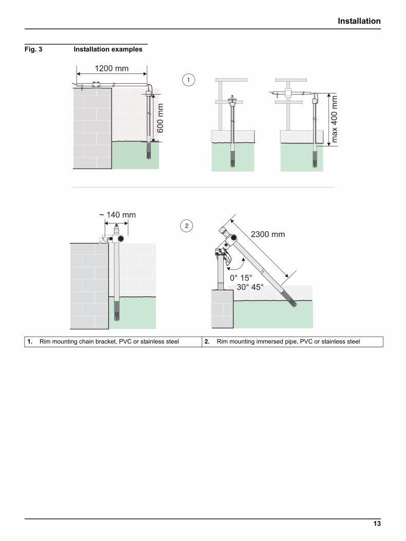
Fig. 3 Installation examples
1. Rim mounting chain bracket, PVC or stainless steel 2. Rim mounting immersed pipe, PVC or stainless steel
13

Installation
14

Section 5 Operation
5.1 Operating the sc controller
The sensor can be operated with all sc controllers. Prior to using the sensor, familiarise yourself with the principle of operation of your controller. Learn how to navigate in the menus and run appropriate functions.
5.2 Sensor setup
When you connect the sensor for the first time, the serial number of the sensor is displayed as the sensor name. You can change the sensor name as follows:
1. Open the MAIN MENU.
2. Choose SENSOR SETUP and accept.
3. Choose the related sensor and accept.
4. Choose CONFIGURE and accept.
5. Choose EDIT NAME and accept.
6. Edit the name and accept to return to the SENSOR SETUP menu.
In the same way complete your system configuration using the commands as per table 5.5 The commands under SENSOR SETUP.
5.3 Sensor data logger
A data memory and event memory per sensor are available via the sc controller. While measured data are saved in the data memory at stipulated intervals, the event memory collects numerous events such as configuration changes, alarms and warning conditions. Both the data memory and the event memory can be read out in CSV format. For information on how you can download the data, please see the controller manual.
5.4 The commands under SENSOR DIAG
SENSOR DIAG
SELECT SENSOR (for several sensors)
ERROR LIST List of all errors that have occurred (see Section 7.1 Error messages)
WARNING LIST List of all warnings that have occurred (see Section 7.2 Warnings)
15

Operation
5.5 The commands under SENSOR SETUP
SENSOR SETUP
SELECT SENSOR (for several sensors)
CALIBRATE
1 POINT BUFFERCalibration using a buffer — normally pH 7, see 5.6.1 Calibration using a buffer solution.
2 POINT BUFFERCalibration using two buffers — normally pH 7 and pH 4 or 10, see 5.6.2 Calibration using two buffer solutions.
1 POINT SAMPLECalibration using a known sample, see 5.6.3 Calibration using a sample solution.
2 POINT SAMPLECalibration using two samples, both with known pH value, see 5.6.4 Calibration using two sample solutions.
PROCESS TEMP Set temperature displayed.
CAL CONFIG
OUTPUT MODE
Choose between:ACTIVE, measured value and thus the outputs signals followthe calibration process;HOLD, the last measured value and thus the output signalare frozen;TRANSFER, the measured value and thus the output signal are setto a defined value andCHOICE, after each calibration you can choose one of the three above options.
CAL REMINDERYou can set when the next calibration is to be performed. The controller then automatically indicates when the next calibration is due.
DEFAULT SETUP Return to the factory settings after prompt for confirmation.
CONFIGURE
EDIT NAME Enter a 10-character name and accept.
SELECT MEASURE Choose between pH and REDOX.
TEMP UNITS Temperature figures in degrees Celsius or Fahrenheit.
LOG SETUP
LOG INTERVAL Choose between the values available or DISABLED.
TEMP. INTERVAL Choose between the values available or DISABLED.
FILTER Enter a value.
DISPLAY FORMAT Choose the display format.
SELECT BUFFER Choose a buffer.
T-SENSOR
AUTOMATIC
MANUAL Enter a value.
MAINS FREQ. Enter the mains frequency.
DEFAULT SETUP Returns to the factory settings after a prompt for confirmation.
DIAG/TEST
PROBE INFO Provides information on driver, software and serial number
CAL DATA Provides information on the offset (T), slope und offset (pH).
SIGNALS Provides information on the raw measured data in mV, pH and °C / F
COUNTERSCounts up after each calibration and compares the value with the setting made under CAL REMINDER
TEST/MAINT Disable OUTPUT during test or maintenance
SERVICE Reset Service Counter
16

Operation
5.6 Sensor calibration (pH)
The electrode is calibrated in the factory and is very stable. As a rule, calibration is only necessary after several weeks or after the electrode of the probe is changed.For continued retention of the measuring accuracy and reproducibility, the manufacturer recommends the replacement of the electrode after approx. one year of operation.
Calibrate the sensor
• after the electrode of the probe is changed,
• as required or
• in accordance or agreement with the authorities.
Note: If you use alkaline buffer solutions, use them quickly. They absorb carbon dioxide from of the air and are therefore relatively unstable.
The calibration comprises one or two sample or buffer solutions with defined pH value and the comparison of the values displayed with the values for the sample or buffer solution. The calibration is straightforward for the user to perform.
5.6.1 Calibration using a buffer solution
1. Ensure the correct buffers solutions are selected in the SENSOR SETUP=>CONFIGURE=>SELECT BUFFER menu.
2. Remove the sensor from the flow of product and clean it.
3. Place the sensor and the buffer solution at the same temperature.
4. Hold the sensor in the buffer solution for 10 minutes and accept to continue.
5. Accept when the measured value has stabilised.
The sensor detects the buffer solution and makes all the necessary settings automatically.
5.6.2 Calibration using two buffer solutions
The calibration is performed in exactly the same way for the calibration with one buffer solution. In addition, the controller prompts you to:
1. Clean the sensor and hold it in the second buffer solution for 10 minutes.
The sensor detects the buffer solution and makes all the necessary settings automatically.
17

Operation
5.6.3 Calibration using a sample solution
1. Remove the sensor from the flow of product and clean it.
2. Place the sensor and the sample solution at the same temperature.
3. Hold the sensor in the sample solution for 10 minutes and accept to continue.
4. Wait until the measured value has stabilised and enter the pH value for the sample solution. The value for the sample can be determined by a laboratory analysis or a comparative indication.
5.6.4 Calibration using two sample solutions
The calibration is performed in exactly the same way for the calibration with one sample solution. In addition, the controller prompts you to:
1. Clean the sensor and hold it in the second sample solution for 10 minutes.
2. Enter the pH value for the second sample solution.
5.7 Sensor calibration (REDOX)
Calibration using a sample solution is available for calibrating the sensor for Redox.
1. Remove the sensor from the flow of product and clean it.
2. Place the sensor and the sample solution at the same temperature.
3. Hold the sensor in the sample solution for 10 minutes and accept to continue.
4. Wait until the measured value has stabilised and enter the value for the sample solution. The value for the sample can be determined by a laboratory analysis or a comparative indication.
18
Operation
5.8 Sensor calibration (temperature)
To calibrate the temperature sensor, proceed as follows:
1. Ensure that the correct temperature unit is selected in the SENSOR SETUP=>CONFIGURE=>TEMP UNITS menu.
2. Open the SENSOR SETUP => CONFIGURE => T-Sensor menu and choose MANUAL.
3. Immerse the probe for a minimum of 10 min. in a reference solution while monitoring the temperature of the solution with a thermometer (measuring accuracy ± 0.1 °C).
4. Compare the temperature displays on the sensor and the thermometer.
5. Enter the value on the thermometer in the controller.
6. Wait until the value displayed has stabilised and accept.
7. The correction factor is calculated and the temperature values will in future be displayed correctly.
5.8.1 Calibrating two sensors simultaneously
1. Start by calibrating the first sensor and when you arrive at the point at which you are prompted to "PRESS ENTER WHEN STABLE".
2. Press the BACK key.
3. Select LEAVE and press accept. The display returns to the display of the measurements. The measured value for the sensor to be calibrated starts to flash.
4. Start the calibration of the other sensor and when you again arrive at the point at which you are prompted to "PRESS ENTER WHEN STABLE".
5. Press the BACK key.
6. Select EXIT and press accept. The display returns to the display of the measurements. The measured values for both sensors start to flash.
7. To return to the calibration menu for the individual sensors, open the main menu, select SENSOR SETUP and accept. Choose the required sensor and accept.
8. When calibration is complete, accept.
19

Operation
20

Section 6 Maintenance
6.1 Maintenance schedule
The following table reflects experience and may, depending on the sector and application, vary significantly from actual requirements.
You can set the calibration interval in the sensor setup. The controller then reminds you when calibration is due.
6.2 Cleaning the sensor
Clean the sensor with a jet of water. If there is still soiling present, use a soft, damp cloth.
6.3 Changing electrode
Change the electrode once a year or if the measurements are excessively inaccurate despite cleaning and calibration.
1. Unscrew the protective cage from the tip of the sensor.
2. Pull out the electrode. If necessary, also lift out the base ring using a screwdriver.
3. Undo the union nut on the connector and replace the electrode.
Fig. 6-1 Changing the electrode
Maintenance task 90 days annual
Clean sensor x
Check sensor for damage x
Renew sensor electrodex
(depending on the application)
Calibration(if necessary)
If necessary as per agreement with the authorities
21

Maintenance
The new electrode is fitted in the reverse order of removal.
1. Slide the new electrode into the sensor until the base ring is in contact with the electrode so that the sensor is sealed.
2. Calibrate the sensor using two buffer solutions (see 5.6.2 Calibration using two buffer solutions).
22

Section 7 Faults, causes, rectification
7.1 Error messages
Possible sensor errors are displayed by the controller.
7.2 Warnings
Possible warning messages are displayed by the controller.
Table 1: Error messages
Error displayed Cause Rectification
*****No communication with the controller
Check the connection to the controller
Check the cable to the controller
Check the 12 V power supply
SENSOR MISSING
FFFFFFFFFFFFFNo communication with the controller
Check the connection to the controller
Check the cable to the controller
Check the 12 V power supply
TEMP TOO LOW Measured temperature < –5 °C Ensure that the medium temperature is > –5 °C.
Check whether the internal resistance of the Pt 100 is approx. 99 Ohm.
TEMP TOO HIGH Measured temperature > +100 °CEnsure that the medium temperature is < +100 °C.
Check whether the internal resistance of the Pt 100 is approx. 138.5 Ohm.
pH TOO LOW pH is lower than –2 pH
Check the sensor for leaks.
Change the electrode.
Change the board.
pH TOO HIGH pH is higher than +14 pH
Check the sensor for leaks.
Change the electrode.
Change the board.
mV TOO LOW mV is lower than –1500 mV
Check the sensor for leaks.
Change the electrode.
Change the board.
mV TOO HIGH mV is higher than +1500 mV
Check the sensor for leaks.
Change the electrode.
Change the board.
Table 2: Warnings
Error displayed Cause Rectification
CAL TOO OLDThe last calibration was more than x days ago. (Setting from the sensor setup)
Calibrate the sensor.Set the calibration interval in the sensor setup.
HUMIDITY BAG The desiccant bag is more than 1000 days old. Please contact service.
REF IMP. LOW Impedance of Reference electrode too low Please contact service.
REF IMP. HGH Impedance of Reference electrode too high Please contact service.
GLASS IMP. LOW Impedance of Glass electrode too low Please contact service.
GLASS IMP. HGH Impedance of Glass electrode too high Please contact service.
23

Faults, causes, rectification
7.3 Important service data
Data Minimum Maximum
CAL DATA
SLOPE 120 % 80 %
Offset pH + 3 pH – 3 pH
Offset ORP + 250 mV – 250 mV
Temperature offset correction + 5 °C – 5 °C
CounterHumidity bag 1000 days
Operating time
24

Section 8 Spare parts
Digital 1200-S sc pH sensor ........................................................................................................... LXV426.99.10001Digital 1200-S sc ORP sensor........................................................................................................ LXV426.99.20001Replacement pH electrode ............................................................................................................................. LZX889Replacement ORP electrode.......................................................................................................................... LZX890Replacement electrode protective cage ......................................................................................................... LZX899Operating instructions....................................................................................................................DOC023.52.03253
AccessoriesCable extension set (0.35 m).......................................................................................................................... LZX847Cable extension set (5 m)............................................................................................................................... LZX848Cable extension set (10 m)............................................................................................................................. LZX849Cable extension set (15 m)............................................................................................................................. LZX850Cable extension set (20 m)............................................................................................................................. LZX851Cable extension set (30 m)............................................................................................................................. LZX852Cable extension set (50 m)............................................................................................................................. LZX853Termination box .............................................................................................................................................5867000Immersed pipe, V4A....................................................................................................................... LZX914.99.01200Immersed pipe, PVC ...................................................................................................................... LZX914.99.02200Chain bracket, V4A..........................................................................................................................LZX914.99.11200Chain bracket, PVC........................................................................................................................ LZX914.99.12200Immersed pipe set, V4A ................................................................................................................. LZX914.99.31200Immersed pipe set, PVC................................................................................................................. LZX914.99.32200U-bolt .............................................................................................................................................................. LZX959
Reagents and standardsStandard solution...............................................................................................................................25M1A1025-115Buffer, pH 7, 500 ml........................................................................................................................................ 3A0421Buffer, pH 4, 500 ml........................................................................................................................................ 3A0422 Buffer, pH 10, 500 ml...................................................................................................................................... 3A0942 Buffer, pH 7, 4 l ................................................................................................................................. 25M1A1016-123Buffer, pH 4, 4 l ................................................................................................................................. 25M1A1014-123Buffer, pH 10, 4 l............................................................................................................................... 25M1A1017-123ORP standard solution, 200 mV, 500 ml........................................................................................... 25M2A1001-115ORP standard solution, 600 mV, 500 ml........................................................................................... 25M2A1002-115ORP standard solution, 200 mV, 4 l................................................................................................. 25M2A1001-123ORP standard solution, 600 mV, 4 l................................................................................................. 25M2A1002-123
25

Spare parts
26

Section 9 Warranty and liability
HACH LANGE GmbH warrants that the product supplied is free of material and manufacturing defects and undertakes the obligation to repair or replace any defective parts at zero cost.
The warranty period for instruments is 24 months. If a service contract is taken out within 6 months of purchase, the warranty period is extended to 60 months.
With the exclusion of the further claims, the supplier is liable for defects including the lack of assured properties as follows: all those parts that, within the warranty period calculated from the day of the transfer of risk, can be demonstrated to have become unusable or that can only be used with significant limitations due to a situation present prior to the transfer of risk, in particular due to incorrect design, poor materials or inadequate finish will be improved or replaced, at the supplier's discretion. The identification of such defects must be notified to the supplier in writing without delay, however at the latest 7 days after the identification of the fault. If the customer fails to notify the supplier, the product is considered approved despite the defect. Further liability for any direct or indirect damages is not accepted.
If instrument-specific maintenance and servicing work defined by the supplier is to be performed within the warranty period by the customer (maintenance) or by the supplier (servicing) and these requirements are not met, claims for damages due to the failure to comply with the requirements are rendered void.
Any further claims, in particular claims for consequential damages cannot be made.
Consumables and damage caused by improper handling, poor installation or incorrect use are excluded from this clause.
HACH LANGE GmbH process instruments are of proven reliability in many applications and are therefore often used in automatic control loops to provide the most economical possible operation of the related process.
To avoid or limit consequential damage, it is therefore recommended to design the control loop such that a malfunction in an instrument results in an automatic change over to the backup control system; this is the safest operating state for the environment and the process.
27

Warranty and liability
28

Section 10 Contact
HACH CompanyWorld HeadquartersP.O. Box 389Loveland, Colorado80539-0389 U.S.A.Tel (800) 227-HACH(800) -227-4224(U.S.A. only)Fax (970) [email protected]
Repair Service in theUnited States:HACH CompanyAmes Service100 Dayton AvenueAmes, Iowa 50010Tel (800) 227-4224(U.S.A. only)Fax (515) 232-3835
Repair Service in Canada:Hach Sales & ServiceCanada Ltd.1313 Border Street, Unit 34Winnipeg, ManitobaR3H 0X4Tel (800) 665-7635(Canada only)Tel (204) 632-5598Fax (204) [email protected]
Repair Service inLatin America, the Caribbean, the Far East, Indian Subcontinent, Africa, Europe, or the Middle East:Hach Company WorldHeadquarters,P.O. Box 389Loveland, Colorado,80539-0389 U.S.A.Tel +001 (970) 669-3050Fax +001 (970) [email protected]
HACH LANGE GMBHWillstätterstraße 11D-40549 DüsseldorfTel. +49 (0)2 11 52 88-320Fax +49 (0)2 11 52 [email protected]
HACH LANGE LTDPacific WaySalfordGB-Manchester, M50 1DLTel. +44 (0)161 872 14 87Fax +44 (0)161 848 73 [email protected]
HACH LANGE LTDUnit 1, Chestnut RoadWestern Industrial EstateIRL-Dublin 12Tel. +353(0)1 460 2522Fax +353(0)1 450 [email protected]
HACH LANGE GMBHHütteldorfer Str. 299/Top 6A-1140 WienTel. +43 (0)1 912 16 92Fax +43 (0)1 912 16 [email protected]
HACH LANGE GMBHRorschacherstrasse 30aCH-9424 RheineckTel. +41 (0)848 55 66 99Fax +41 (0)71 886 91 [email protected]
HACH LANGE FRANCE S.A.S.8, mail Barthélémy ThimonnierLognesF-77437 Marne-La-Vallée cedex 2Tél. +33 (0) 820 20 14 14Fax +33 (0)1 69 67 34 [email protected]
HACH LANGE NV/SAMotstraat 54B-2800 MechelenTel. +32 (0)15 42 35 00Fax +32 (0)15 41 61 [email protected]
DR. LANGE NEDERLAND B.V.Laan van Westroijen 2aNL-4003 AZ TielTel. +31(0)344 63 11 30Fax +31(0)344 63 11 [email protected]
HACH LANGE APSÅkandevej 21DK-2700 BrønshøjTel. +45 36 77 29 11Fax +45 36 77 49 [email protected]
HACH LANGE ABVinthundsvägen 159ASE-128 62 SköndalTel. +46 (0)8 7 98 05 00Fax +46 (0)8 7 98 05 [email protected]
HACH LANGE S.R.L.Via Rossini, 1/AI-20020 Lainate (MI)Tel. +39 02 93 575 400Fax +39 02 93 575 [email protected]
HACH LANGE S.L.U.Edificio SeminarioC/Larrauri, 1C- 2ª Pl.E-48160 Derio/VizcayaTel. +34 94 657 33 88Fax +34 94 657 33 [email protected]
HACH LANGE LDAAv. do Forte nº8Fracção MP-2790-072 CarnaxideTel. +351 214 253 420Fax +351 214 253 [email protected]
HACH LANGE SP. ZO.O.ul. Krakowska 119PL-50-428 WrocławTel. +48 801 022 442Zamówienia: +48 717 177 707Doradztwo: +48 717 177 777Fax +48 717 177 [email protected]
HACH LANGE S.R.O.Zastrčená 1278/8CZ-141 00 Praha 4 - ChodovTel. +420 272 12 45 45Fax +420 272 12 45 [email protected]
HACH LANGE S.R.O.Roľnícka 21SK-831 07 Bratislava – VajnoryTel. +421 (0)2 4820 9091Fax +421 (0)2 4820 [email protected]
HACH LANGE KFT.Vöröskereszt utca. 8-10.H-1222 Budapest XXII. ker.Tel. +36 1 225 7783Fax +36 1 225 [email protected]
HACH LANGE S.R.L.Str. Căminului nr. 3,et. 1, ap. 1, Sector 2RO-021741 BucureştiTel. +40 (0) 21 205 30 03Fax +40 (0) 21 205 30 [email protected]
HACH LANGE8, Kr. Sarafov str.BG-1164 SofiaTel. +359 (0)2 963 44 54Fax +359 (0)2 866 15 [email protected]
HACH LANGE SUANALİZ SİSTEMLERİ LTD.ŞTİ.Ilkbahar mah. Galip Erdem Cad. 616 Sok. No:9TR-Oran-Çankaya/ANKARATel. +90312 490 83 00 Fax +90312 491 99 [email protected]
29

Contact
HACH LANGE D.O.O.Fajfarjeva 15SI-1230 DomžaleTel. +386 (0)59 051 000Fax +386 (0)59 051 [email protected]
ΗΑCH LANGE E.Π.Ε.Αυλίδος 27GR-115 27 ΑθήναΤηλ. +30 210 7777038Fax +30 210 [email protected]
HACH LANGE D.O.O.Ivana Severa bbHR-42 000 VaraždinTel. +385 (0) 42 305 086Fax +385 (0) 42 305 [email protected]
HACH LANGE MAROC SARLAUVilla 14 – Rue 2 Casa PlaisanceQuartier Racine ExtensionMA-Casablanca 20000Tél. +212 (0)522 97 95 75Fax +212 (0)522 36 89 [email protected]
HACH LANGE OOOFinlyandsky prospekt, 4ABusiness Zentrum “Petrovskyfort”, R.803RU-194044, Sankt-PetersburgTel. +7 (812) 458 56 00Fax. +7 (812) 458 56 [email protected]
30

Appendix A ModBUS Register Information
Table 3 Sensor ModBUS Registers
Tag Name Register # Data TypeLengt
hR/W Description
pH measurement 40001 Float 2 R pH measurement
ORP measurement 40003 Float 2 R ORP measurement
Temperature measurement 40005 Float 2 R Temperature measurement
Raw pH measurement 40007 Float 2 R Raw pH measurement
mV Raw measurement 40009 Float 2 R mV Raw measurement
Raw Temperature measurement 40011 Float 2 R Raw Temperature measurement
Main Measurement Parameter 40013 Integer 1 R Main Measurement Tag
Temperature Measurement Param. 40014 Integer 1 R Temp Measurement Tag
Sensor Name[0] 40015 Integer 1 R/W Sensor Name[0]
Sensor Name[1] 40016 Integer 1 R/W Sensor Name[1]
Sensor Name[2] 40017 Integer 1 R/W Sensor Name[2]
Sensor Name[3] 40018 Integer 1 R/W Sensor Name[3]
Sensor Name[4] 40019 Integer 1 R/W Sensor Name[4]
Sensor Name[5] 40020 Integer 1 R/W Sensor Name[5]
Function code 40021 Integer 1 Function code
Next Step 40022 Integer 1 Next Step
Password 40023 Pass 1 R/W Password
Serial Number[0] 40024 Integer 1 R/W Serial Number[0]
Serial Number[1] 40025 Integer 1 R/W Serial Number[1]
Serial Number[2] 40026 Integer 1 R/W Serial Number[2]
pH/ORP toogle 40027 Bit 1 R/W pH/ORP toogle
Temperature unit toogle 40028 Bit 1 R/W Temperature unit toogle
pH display format 40029 Bit 1 R/W pH display format XX.X or XX.XX
Buffer Type 40030 Bit 1 R/W Buffer type
--- 40031 Integer 1 R/W Internal use
--- 40032 Integer 1 R/W Internal use
Averaging 40033 Integer 1 R/W Averaging
Automatic/Manual toogle 40034 Bit 1 R/W Automatic/Manual toogle
Manual Temperature unit 40035 Integer 1 R/W Manual Temperature unit
Manual Temperature 40036 Float 2 R/W Manual Temperature
50/60 Hz toogle 40038 Bit 1 R/W 50/60 Hz toogle
Output Mode 40039 Integer 1 R Internal use
--- 40040 Integer 1 R Internal use
--- 40041 Integer 1 R Internal use
--- 40042 Integer 1 R Internal use
--- 40043 Integer 1 R Internal use
--- 40044 Integer 1 R Internal use
--- 40045 Integer 1 R Internal use
--- 40046 Integer 1 R Internal use
--- 40047 Integer 1 R Internal use
--- 40048 Integer 1 R Internal use
--- 40049 Float 2 R Internal use
31

ModBUS Register Information
--- 40051 Float 2 R Internal use
--- 40053 Float 2 R Internal use
Temperature Offset 40055 Float 2 R Internal use
Temperature Offset unit 40057 Integer 1 R Internal use
pH Buffer 1 Measurement 40058 Float 2 R Internal use
pH Buffer 2 Measurement 40060 Float 2 R Internal use
ORP Buffer 1 Measurement 40062 Float 2 R Internal use
Output Mode 40064 Integer 1 R Internal use
Software version 40065 Float 2 R Software version
Serial Number String[0] 40067 Integer 1 R/W Internal use
Serial Number String[2] 40068 Integer 1 R/W Internal use
Serial Number String[4] 40069 Integer 1 R/W Internal use
Serial Number String[6] 40070 Integer 1 R/W Internal use
Serial Number String[8] 40071 Integer 1 R/W Internal use
Serial Number String[10] 40072 Integer 1 R/W Internal use
--- 40073 Integer 1 R Internal use
--- 40074 Integer 1 R Internal use
pH Offset 40075 Float 2 R pH Calibration Offset
pH Slope 40077 Float 2 R pH Calibration slope
ORP Offset 40079 Float 2 R ORP Calibration Offset
ORP Slope 40081 Float 2 R ORP Calibrtion slope
Calibration Return Status 40083 Integer 1 R Calibration Return Status
Time from last Calibration 40084 Integer 1 RDelay the isnstrument has been calibrated last time
Time from start up 40085 Integer 1 R Time the system is running
Time to exchange Humidity bag 40086 Integer 1 R Time the humidity bag has been used
DriverVersion_float 40087 Float 2 R Driver version
--- 40089 Float 2 R Internal use
Measurement Logging Interval 40091 Integer 1 R/W Sensor Data logging interval
Temperature Logging Interval 40092 Integer 1 R/W Temperature logging interval
Electrode Impedance Meas. Interval 40093 Integer 1 R/W Impedance measurement interval
Glass Impedance Measurement 40094 Float 2 R Glass impedance measurement
Reference Impedance Measurement 40096 Float 2 R Reference impedance measurement
Table 3 Sensor ModBUS Registers
Tag Name Register # Data TypeLengt
hR/W Description
32