Embed Size (px)
Citation preview

July Nov 2015 doc.: IEEE 802.11-14/0980r1
4
IEEE P802.11Wireless LANs
TGax Simulation Scenarios
Date: July 16, 2015
Authors and ContributorsName Company Address Phone Email
Simone Merlin Qualcomm
5775 Morehouse Dr
San Diego, [email protected]
Gwen Barriac Qualcomm
Hemanth Sampath Qualcomm
Laurent Cariou Orange
Thomas Derham Orange
Jean-Pierre Le Rouzic Orange
Robert Stacey Intel
Minyoung Park Intel
Chittabrata Ghosh Intel
Ron Porat Broadcom
Nihar Jindal Broadcom
Yasuhiko Inoue NTT
Yusuke Asai NTT
Yasushi Takatori NTT
Akira Kishida NTT
Akira Yamada NTT Docomo
Submission page 1 Simone Merlin (Qualcomm)

July Nov 2015 doc.: IEEE 802.11-14/0980r1
4
Reza Hedayat Cisco
Sayantan Choudhury Nokia
Klaus Doppler Nokia
Jarkko Kneckt Nokia
Enrico-Henrik Rantala Nokia
David Xun Yang Huawei
Yujian (Ross) Huawei
Zhou Lan Huawei
Jiayin Zhang Huawei
Yanchun Li Huawei
Yunbo Li Huawei
Jiyong Pang Huawei
Hongjia Su Huawei
Yingpei Lin Huawei
Wookbong Lee LGE
HanGyu Cho LGE
Suhwook Kim LGE
HyeYoung Choi LGE
Joseph Levy InterDigital
Frank La Sita InterDigital
Jinjing Jiang Marvell
Liwen Chu Marvell
Yakun Sun Marvell
Filip Mestanov Ericsson
Guoqing Li Apple
Scott MarinNokia Solutions and Networks
Submission page 2 Simone Merlin (Qualcomm)

July Nov 2015 doc.: IEEE 802.11-14/0980r1
4
Eisuke Sakai Sony
William Carney Sony
Bo Sun ZTE
Kaiying Lv ZTE
Yao Ke ZTE
Han Zhiqiang ZTE
Chao-Chun Wang Mediatek
Russell Huang Mediatek
ChingHwa Yu Mediatek
James Yee Mediatek
Eric Wong Apple
Joonsuk Kim Apple
Xiaofei Wang Interdigital
Abstract
This document describes the simulation scenarios for the 11ax TG.
Table of Contents
Abstract.............................................................................................................................................2
Revisions...........................................................................................................................................3
Introduction.......................................................................................................................................6
Notes on this version.........................................................................................................................6
Scenarios summary...........................................................................................................................7
Considerations on the feedback from WFA.................................................................................8
Common Parameters for all simulation Scenarios........................................................................9
Power State Transitions and Power Consumption........................................................................9
Submission page 3 Simone Merlin (Qualcomm)

July Nov 2015 doc.: IEEE 802.11-14/0980r1
4
Following state transition is used for power modelling in simulations and performance evaluation......................................................................................................................................9
Common Power Model Parameters for all simulation Scenarios...............................................10
1 - Residential Scenario..................................................................................................................13
2 – Enterprise Scenario...................................................................................................................17
Interfering scenario for scenario 2..............................................................................................21
3 - Indoor Small BSSs Scenario.....................................................................................................23
Interfering Scenario for Scenario 3.............................................................................................29
4 - Outdoor Large BSS Scenario....................................................................................................32
4a- Outdoor Large BSS + Residential Scenario.............................................................................38
Scenarios for calibration of MAC simulator...................................................................................39
Common parameters...................................................................................................................39
Test 1a: MAC overhead w/out RTS/CTS..................................................................................40
Test 1b: MAC overhead w RTS/CTS........................................................................................42
Test 2a: Deferral Test 1..............................................................................................................44
Test 2b: Deferral Test 2..............................................................................................................45
Test 3: NAV deferral..................................................................................................................46
Test 4: Deferral Test for 20 and 40MHz BSSs...........................................................................47
Test 5: Power Save Mechanism Test..........................................................................................49
Scenarios for calibration of Box5 simulator...............................................................................52
Calibration results...........................................................................................................................55
Annex 3 - Templates.......................................................................................................................56
References.......................................................................................................................................56
Revisions
Revisions of document 13/1001
Revision Comments Date
R0 Initial draft template Aug 28th
R1 Sept 15th 2013
Submission page 4 Simone Merlin (Qualcomm)

July Nov 2015 doc.: IEEE 802.11-14/0980r1
4
R2 Made it consistent with document 1000r2 Sept 16th 2013
R3 Included Scenario 1 from 1081r0
Included Scenario 2 from 722r2
Included Scenario 3 and 4 from 1248r0; scenario 3 likely compatible with documents 722 and 1079.
Included concept from 1176r0
Added References
Updated co-authors
Oct 4th 2013
R4 Minor corrections Oct 4th 2013
R5 Added description for scenario 4a (Simone (Qualcomm), Ron (Broadcom))
Tentative addition of contributions related to traffic models; more discussion is needed:
Added video traffic models from #1335 (Guoqing Li, Intel)
Table for traffic models (Bill, Sony) Management Traffic profile and % of unassociated
users (Reza, Cisco) Application activity intervals (Huai-Rong, Samsung)
Indicated that legacy STAs can be present (Various)
Indicated that legacy APs can be present in scenario 1(Liwen, Marvell)
Indication of antenna height (Wookbong, LG)
RTS Thresholds (Liwen, Marvell)
Primary channel location (Liwen (Marvell), Klaus (Nokia))
Clarified that all BSSs are either all at 2.4GHz, or all at 5GHz (Liwen, Marvell)
Some changes on traffic model for Residential Scenario (Klaus, Nokia)
Initial indications of channel model (various, Joseph,
Nov 14th 2013
Submission page 5 Simone Merlin (Qualcomm)

July Nov 2015 doc.: IEEE 802.11-14/0980r1
4
(InterDigital), Wookbong (LG); needs more discussion)
Clarification on non-HEW definition.
Other comments from Jason, David, Wookbong, Thomas
R6 Modified the number of APs in scenario 2 (Filip (Ericsson))
Add description of the interference scenario for Scenario 2 (David (Huawei))
Added considerations on feedback from WFA
R7 Editorials corrections and accepted all track changes to ease identification of future changes (Wookbong)
Mar 2014
R8 Update on the management traffic parameters (Reza)
Various updates (Yakun)
Addition of multicast traffic on Scenario 3 (Eisuke)
Updated Scenarion 1 with pathloss model and calibration parameters (Simone, 14/355r0)
Updates on Residential Scenario parameters (Jarkko, Klaus)
Mar 2014
R9 Updated Interfering scenario for scenario 2 which I missed in previous version (from Ross)
April 2014
Revisions of document 14/0621
Revision Comments Date
R0 Cleanup, removal of old comments, resolution of (hopefully) non-controversial TBDs. To see all the comments, please refer to r9
Included comments from Jarkko: added a tentative set of common parameters upfront; removed several comments.
Included comments from Suhwook on the allocation of channels from 14/0625
May 2014
Submission page 6 Simone Merlin (Qualcomm)

July Nov 2015 doc.: IEEE 802.11-14/0980r1
4
Included VDI and Gaming in the traffic from doc 14/0594, 14/0595.
Removed Annex 2, which is now part of Evaluation Methodology document
R1 Modified the pathloss for Scenario 1, based on 14/577r0 May 2014
R2 Removed section on calibration scenarios: people need more time to review
Corrected pathloss formula for Scenario 1
Accepted all the changes to have a clean baseline
May 2014
R2 was accepted as baseline for the TG Simulation Scenario document on 5/14/14
R3 Added calibration scenarios for MAC simulator May 2014
R4 May 2014
Chnaged document number to 14/0980 due to server issues
R0 Changes from contributions 896r0, 972r0, 967r5 July 2014
R1 Corercted some typos
This version adopted via motion on 7/17/14
July 2014
R2 Accepted earlier changes and updated authors list and July 2014
R3 Added text for power save model from 1286r1, calibration from 1272r1; added a reference to a MAC calibration results report
September 2014
R4 Accepted September 2014
R5 Corrected text in Test 2
Corrected figure in Test 3
1496r5
Updated revision number of calibration results
November 2014
R6 Modifictions to Test 1a based on 78r2 January 2015
Submission page 7 Simone Merlin (Qualcomm)

July Nov 2015 doc.: IEEE 802.11-14/0980r1
4
Modifications to Test 5 based on 172r1
Added Gaming traffic profile text from 61r6
R10 Modifications to Test 4 from 441r3
Modifications for distinction between shallow and deep sleep based on 304r2
Clarification on Beacon size 316r5
March 2015
R11-12 Traffic profiles from 0373r4
Power consumption transision 576r2
Calibration scenario for Box 5 681r0
May 2015
R13 Correction from Yingpei
Power numbers from 833r2
Clarification on channel model scenario 4 581r0
July 2015
R14 Small revision July 2015
R15 Power Paramters from 1100r2
Wrap around model 1360r0
Minimum Distance 1362r0
Nov 2015
Submission page 8 Simone Merlin (Qualcomm)

July Nov 2015 doc.: IEEE 802.11-14/0980r1
4
Introduction
This document defines simulation scenarios to be used for
- Evaluation of performance of features proposed in HEW - Generation of results for simulators calibration purpose.
Each scenario is defined by specifying
– Topology: AP/STAs positions, P2P STAs pair positions, obstructions , layout, propagation model
– Traffic model
– UL: STA - AP traffic
– DL: AP – STA traffic
– P2P traffic (tethering, Soft-APs, TDLS)
– ‘Idle’ management (generating management traffic such as probes/beacons)
– Power model
– List of PHY, MAC, Management parameters
– We may want to fix the value of some parameters to limit the degrees of freedom, and for calibration
– Optionally, some STAs may use legacy (11n/ac) operation parameters, if required to prove effectiveness of selected HEW solutions
– An interfering scenario (its performance optionally tracked)
– Not managed or managed by a different entity than the one of the main scenario
– Defined by its own Topology, Traffic model and parameters
Per each of above items, the scenario description defines a detailed list of parameters and corresponding values.
Values not specified can be set to any value. Submission page 9 Simone Merlin (Qualcomm)

July Nov 2015 doc.: IEEE 802.11-14/0980r1
4
Values included in square brackets [] are default values to be used for calibration.
All other parameters values not included in [], are to be considered mandatory for performance evaluation.
Simulation results should be presented together with the specification of the value used per each of the parameters in the tables.
Notes on this version
This document builds on document 13/1001r9, which was developed during the HEW SG phase.
The document consolidates contributions on scenarios details from various authors and reflects the comments/submissions received. It is not a final version by any means and is subject to changes based on further discussion and feedback.
Major TBDs
- Traffic models
- Channel models an penetration losses per scenario
o Not clear agreement on which channel models to be used in each scenario; some tentative included in the document
- Calibration scenarios;
- Some other topics under discussion refer to simulation methodology/parameters that can be common and fixed across all scenarios, hence they may be directly included in the Evaluation Methodology document or in an appendix of this documents
o Rate adaptation model
o Use of wrap around for scenarios 3 and 4?
Discussion is needed; Use of wrap around with CSMA may create artefacts
Submission page 10 Simone Merlin (Qualcomm)

July Nov 2015 doc.: IEEE 802.11-14/0980r1
4
o Is the ‘random’ position of STAs randomly generated by each simulation run, or are we going to have a file with common positions?
o Several channel model and RF related parameters that are likely to be common and fixed across scenarios see #1383
Scenarios summary
This document reports the initial agreement according to document 11-13/1000r2.
Scenario
NameTopology Management
Channel
ModelHomogeneity
~Traffic
Model
1 Residential
A - Apartment building
e.g. ~10m x 10m apartments in a multi-floor building
~10s of STAs/AP, P2P pairs
Unmanaged Indoor Flat Home
2 Enterprise
B - Dense small BSSs with clusters
e.g. ~10-20m inter AP distance,
~100s of STAs/AP, P2P pairsManaged Indoor Flat
Enterprise
3 Indoor Small BSS Hotspot
C - Dense small BSSs, uniform
e.g. ~10-20m inter AP distance
~100s of STAs/AP, P2P pairs
Mobile
4 Outdoor Large BSS Hotspot
D - Large BSSs, uniform
e.g. 100-200m inter AP distance
~100s of STAs/AP, P2P pairs
Managed Outdoor Flat Mobile
Submission page 11 Simone Merlin (Qualcomm)

July Nov 2015 doc.: IEEE 802.11-14/0980r1
4
4a
Outdoor Large BSS Hotspot
+ Residential
D+AManaged + Unmanaged Hierarchical
Mobile + Home
Considerations on the feedback from WFA
Document 11-13/1443 includes feedback from WFA regarding prioritization of usage models.
Document 11-13/1456r1 shows a mapping between the prioritized usage models and the simulation scenarios in this document (as of r5).
The summary is copied here:
• Mapping– 1b Airport / train station Scenario 3 – 1e E-education Scenario 2– 3a Dense apartment building Scenario 1– 4b Pico-cell street deployment Scenario 4– 2b Public transportation ??
• No good match with existing scenarios
• Is usage model 2b relevant for HEW, in the opinion of the SG?– Usage model 2b is essentially ‘single cell’, which is a departure
from ‘Dense scenarios’ scope of HEW • High density of STAs but likely just 1 or few APs
– Goal of simulation scenarios is to capture key issues, and for proof of solutions
– If considered not relevant: our current simulation scenarios are enough
– If considered relevant: we need to either add one more scenario, or fit it into an existing one (preferred)
• E.g. can it fit as a special case of Scenario 2 or 3?
Submission page 12 Simone Merlin (Qualcomm)

July Nov 2015 doc.: IEEE 802.11-14/0980r1
4
Submission page 13 Simone Merlin (Qualcomm)

July Nov 2015 doc.: IEEE 802.11-14/0980r1
4
Common Parameters for all simulation Scenarios
Each simulation scenario shall use the PHY and MAC parameters as defined below. If a scenario changes any value of these parameters, then the changed value is listed in the simulation scenario.
PHY parameters
BW All BSSs either all at 2.4GHz, or all at 5GHz
[20MHz BSS at 2.4GHz, or 80 MHz BSS at 5GHz]
Data Preamble Type [2.4GHz, 11n; 5GHz, 11ac]
STA TX Power 15 dBm per antenna
AP TX Power 20 dBm per antenna
P2P TX Power 15 dBm per antenna
AP Number of TX antennas All APs with [2] or all with 4 antennas
AP Number of RX antennas All APs with [2] or all with 4 antennas
STA Number of TX antennas All STAs with [1] or all with 2 antennas
STA Number of RX antennas All HEW STAs with [1] or all with 2 antennas
AP antenna gain +0dBi
STA antenna gain -2dBi
Noise Figure 7dB
Distance-based Path Loss Computed on the basis of 3-D distance, with a minimum 3-D distance of 1 meter. Formulas shall be evaluated with carrier frequency equal to 2.4GHz for channels within the 2.4 GHz band, and with carrier frequency equal to 5GHz for channels within the 5 GHz band.
Submission page 14 Simone Merlin (Qualcomm)

July Nov 2015 doc.: IEEE 802.11-14/0980r1
4
MAC parameters
Access protocol parameters [EDCA with default parameters]
Aggregation [A-MPDU / max aggregation size / BA window size, No A-MSDU, with immediate BA]
Max number of retries Max retries: 10
RTS/CTS Threshold [no RTS/CTS]
Power State Transitions and Power Consumption
Following state transition is used for power modelling in simulations and performance evaluation
Submission page 15 Simone Merlin (Qualcomm)

July Nov 2015 doc.: IEEE 802.11-14/0980r1
4
Common Power Model Parameters for all simulation Scenarios
Power State parameters
Average Current Consumption [mA]
Voltage = 1,1V,
Band = { 2.4 GHz, 5 GHz }, NSS = { 1 },
Number of TX/RX antennas = { 1 }, TX power per antenna = { 15 dBm }
Power State Bandwidth = { 20 MHz } Bandwidth = { 40 MHz } Bandwidth = { 80 MHz }
Transmit 280 mA 280 mA 280 mA
Receive 100 mA 140 mA 200 mA
Listen 50 mA 60 mA 75 mA
Shallow Sleep
0.9 mA 0.9 mA 0.9 mA
Deep Sleep TBD0.09mA TBD0.09mA TBD0.09mA
Transmit power state is defined as the state when the STA is sending a PPDU.
Receive power state is defined as the state when the STA is receiving a PPDU.
Listen power state is defined as the state when the STA is performing CCA or actively looking for the presence of a PPDU.
Submission page 16 Simone Merlin (Qualcomm)

July Nov 2015 doc.: IEEE 802.11-14/0980r1
4
Deep sleep power state of a wireless module is defined as a sleep state with the wireless radio turned off, i.e., RF, baseband and MAC processors are all switched off. The only power consumed by the wireless module is leakage power.
Deep Sleep power state is defined as a sleep state with the least (non-zero) power consumed and the longest transition time to Listen state.
Shallow sleep power state of a wireless module is defined as a sleep state with baseband and MAC processors turned on, but RF is switched off.Shallow Sleep power state is defined as a sleep state when the STA consumes more power but transitions faster to Listen state when compared to the Deep Sleep power state.*
* For calibration purpose, only Shallow Sleep power state may be used for the sleep state (see Test 5).
Power Transition parameters
State Transitions Transition Time (ms) Average Power Consumption (mW)
Transmit ⬄ Listen TTL=0.01ms 75mW
Receive ⬄ Listen 0.001ms 55mW
Listen Transmit TLT = 0.01ms PLT = 100mW
Transmit Shallow Sleep TTS=0.01ms PTS = 15mW
Receive Shallow Sleep TRS=0.2ms PRS = 15mW
Listen ⬄ Shallow Sleep TLS=0.2msPLS = 5mW
Shallow Sleep Listen 0.5 ms (TSL)
Listen Deep Sleep TLD=1ms PDS = 5mW
Submission page 17 Simone Merlin (Qualcomm)

July Nov 2015 doc.: IEEE 802.11-14/0980r1
4
Deep Sleep Listen TSDL = 103ms
Power Save Mechanism parameters
Mechanism Parameter Definition/ValuesPick one value from the
Suggested Set of Simulation Values **
Power save mode (PSM)
Beacon Interval (BI) 100 TU 100 TU
DTIM Integer in unit of BI { 1, 3 }
PSM timeout Length of time before
STA goes to sleep { 50, 100, 200 } ms
Pre-Target Beacon Transmission Time
(TBTT)
Length of time before a STA wakes before
Beacon { 0 } ms
Beacon timeoutLength of time after
TBTT{ 5 } ms
Power save polling (PSP)
Beacon Interval 100 TU 100 TU
DTIM Integer in unit of BI { 1, 3 }
Pre-Target Beacon Transmission Time
(TBTT)
Length of time before a STA wakes before
Beacon { 0 } ms
Beacon timeoutLength of time after
TBTT{ 5 } ms
Unscheduled automatic power save delivery (U-
Beacon Interval 100 TU 100 TU
DTIM Integer in unit of BI { 1, 3 }
Submission page 18 Simone Merlin (Qualcomm)

July Nov 2015 doc.: IEEE 802.11-14/0980r1
4
APSD)
Max SP Length
Indicate the maximum number of buffered
MSDUs, A-MSDUs, and MMPDUs that AP may
deliver per SP
{ 2, 4, 6, ∞ }
AC Access Category
All ACs are both delivery and trigger
enabled
Pre-Target Beacon Transmission Time
(TBTT)
Length of time before a STA wakes before
Beacon { 0 } ms
Beacon timeoutLength of time after
TBTT{ 5 } ms
** Simulation results presented should clearly indicated what values are used in the generating the simulation results
Submission page 19 Simone Merlin (Qualcomm)

July Nov 2015 doc.: IEEE 802.11-14/0980r1
4
1 - Residential Scenario
(Initial version from documents 11-13/1081r0, 786)
Topology
Figure 1 - Residential building layout
Parameter Value
Environment description
Multi-floor building
• 5 floors, 3 m height in each floor
• 2x10 apartments in each floor
• Apartment size:10m x 10m x 3m
APs location In each apartment, place AP in random xy-locations (uniform distribution) at z = 1.5 m above the floor level of the apartment.
AP Type M APs in the building
Submission page 20 Simone Merlin (Qualcomm)

July Nov 2015 doc.: IEEE 802.11-14/0980r1
4
AP_1 to AP_M1: HEWAP_{M1+1} to AP_M: non-HEW
M = Number of Apartments = 100
M1 = [100]
Non-HEW = 11b/g/n in 2.4GHz
Non-HEW = 11ac in 5GHz
STAs location In each apartment, place STAs in random xy-locations (uniform distribution) at z = 1.5m above the floor level of the apartment
Number of STA
and STAs type
N STAs in each apartmentSTA_1 to STA_N1: HEWSTA_{N1 +1} to STA_N: non-HEW
N = [2] or N = 10
N1 = [N]
Non-HEW = 11b/g (TBD) in 2.4GHz
Non-HEW = 11ac (TBD) in 5GHz
Channel Model
And Penetration Losses
Fading model
TGac channel model D NLOS for all the links.
Pathloss model
PL(d) = 40.05 + 20*log10(fc/2.4) + 20*log10(min(d,5)) + (d>5) *
Submission page 21 Simone Merlin (Qualcomm)

July Nov 2015 doc.: IEEE 802.11-14/0980r1
4
35*log10(d/5) + 18.3*F^((F+2)/(F+1)-0.46) + 5*W
– d = max(3D distance [m], 1)
– fc = frequency [GHz]
– F = number of floors traversed
– W = number of walls traversed in x-direction plus number of walls traversed in y-direction
Shadowing
Log-normal with 5 dB standard deviation, iid across all links
PHY parameters
MCS [use MCS0 for all transmissions] or
[use MCS7 for all transmissions]
GI Short
AP #of TX antennas All HEW APs with [2] or all with 4
AP #of RX antennas All HEW APs with [2] or all with 4
STA #of TX antennas All HEW STAs with [1] or all with 2
STA #of RX antennas All HEW STAs with [1] or all with 2
MAC parameters
Access protocol parameters
[EDCA with default parameters according to traffic class]
Center frequency, BSS BW and primary channels Operating channel:
2.4GHz: random assignment of 3 20MHz non-overlapping channels 5GHz: random assignment of [3] or 5 80MHz non-overlapping channels, with random selection of primary channel per operating channel
Submission page 22 Simone Merlin (Qualcomm)

July Nov 2015 doc.: IEEE 802.11-14/0980r1
4
Aggregation [A-MPDU / 64 MPDU aggregation size / BA window size, No A-MSDU, with immediate BA]
Max # of retries Max retries: 10
RTS/CTS Threshold [No RTS/CTS]
Association X% of STAs in an apartment are associated to the AP in the apartment; 100-X% of the STAs are not associated
[X=100]
Management Each AP is independently managed
Traffic model
For Calibration:
Use full buffer traffic Downlink only or Uplink only BE class
For performance tests:
Submission page 23 Simone Merlin (Qualcomm)

July Nov 2015 doc.: IEEE 802.11-14/0980r1
4
Traffic model for each apartment
Sim Traffic Identifier
Source/Sink Traffic Model1 Traffic Model Class Identifier2
Directional3 Number of Traffic
Services Assigned to STAs in Sim Population
(Source/Sink)4
AC
D1 AP/STA Buffered Video Streaming
BV6 Asymmetric Bi-directional
2/2 VI
D2 AP/STA Buffered Video Streaming
BV3 Asymmetric Bi-directional
4/4 VI
D3 AP/STA FTP FTP Asymmetric Bi-directional
2/2 BE
D4 AP/STA HTTP HTTP Asymmetric 4/4 BE
Submission page 24 Simone Merlin (Qualcomm)

July Nov 2015 doc.: IEEE 802.11-14/0980r1
4
Bi-directional
D5 AP/STA Gaming GMG Asymmetric Bi-directional
3/3 VI
D6 AP/STA VoIP VOIP Symmetric Bi-directional
2/2 VO
D7 AP/STA MGMT: Beacon
220 octets long Beacon frame @ 1 Mbps in 2.4 GHz/
@ 6 Mbps in 5 GHz is transmitted
every 100 TUs
Unidirectional 1/0 VI
U1 STA/AP Buffered Video Streaming
BV3 Asymmetric Bi-directional
1/1 VI
U2 STA/AP FTP FTP Asymmetric Bi-directional
2/2 BE
U3 STA/AP Gaming GMG Asymmetric Bi-directional
3/3 VI
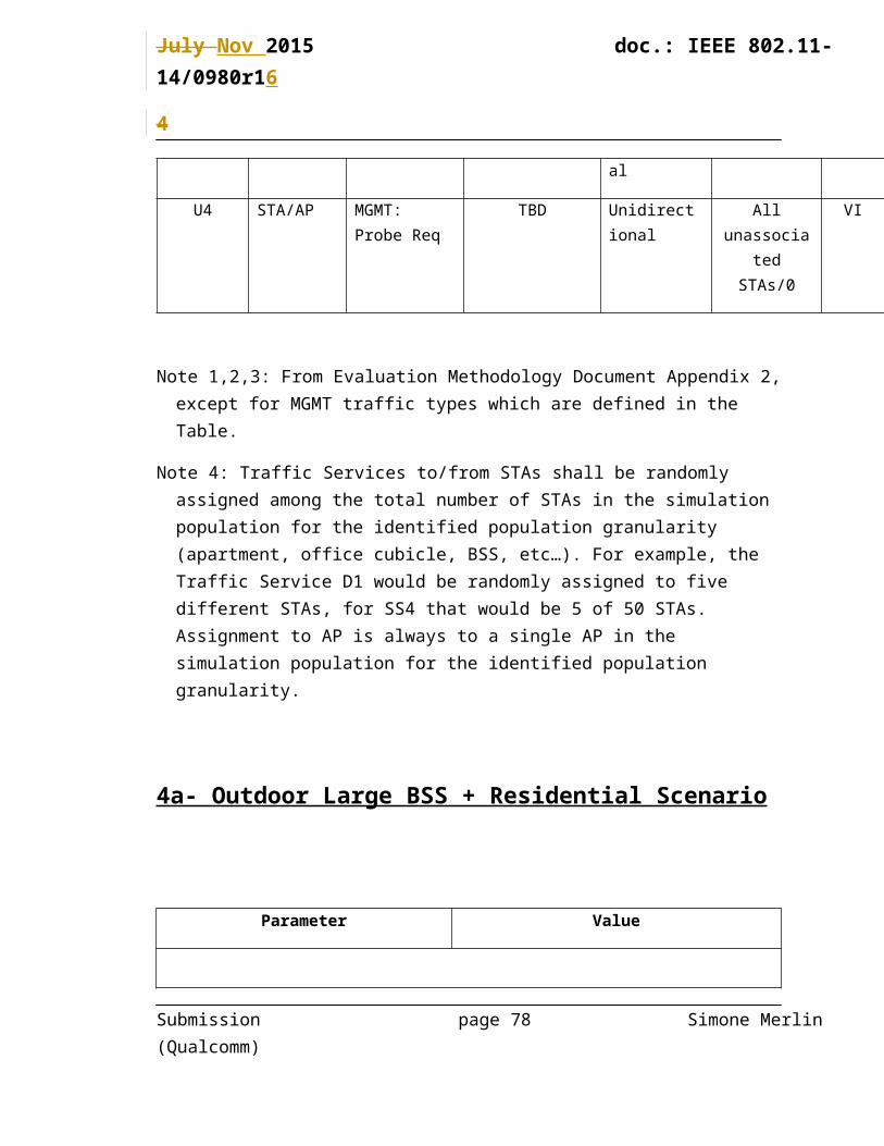
U4 STA/AP MGMT: Probe Req
TBD Unidirectional All unassociated
STAs/0
VI
Note 1,2,3: From Evaluation Methodology Document Appendix 2, except for MGMT traffic types which are defined in the Table.
Note 4: Traffic Services to/from STAs shall be randomly assigned among the total number of STAs in the simulation population for the identified population granularity (apartment, office cubicle, BSS, etc…). For example, the Traffic Service D1 would be randomly assigned to two different STAs, for SS1 that would be 2 of 10 STAs. Assignment to AP is always to a single AP in the simulation population for the identified population granularity.
Submission page 25 Simone Merlin (Qualcomm)

July Nov 2015 doc.: IEEE 802.11-14/0980r1
4
2 – Enterprise Scenario
(Initial version form the Wireless Office scenario in 11/722r2)
Parameter Value
Topology
Figure 2 - BSSs within the building floor
Submission page 26 Simone Merlin (Qualcomm)

July Nov 2015 doc.: IEEE 802.11-14/0980r1
4
Figure 3 - STAs clusters (cubicle) and AP positions within a BSS
Figure 4 - STAs within a cluster
Topology Description Office floor configuration
a. 8 offices (see Error: Reference source not found)b. 64 cubicles per office (see Error: Reference source not
found)c. Each cubicle has 4 STAs (see Figure 4)
STA1: laptop
STA2: monitor
Submission page 27 Simone Merlin (Qualcomm)

July Nov 2015 doc.: IEEE 802.11-14/0980r1
4
STA3: smartphone or tablet
STA4: Hard disk
APs location 4 APs per office
Installed on the ceiling at:
AP1: (x=5,y=5,z=3)
AP2: (x=15,y=5,z=3)
AP3: (x=5,y=15,z=3)
AP4: (x=15,y=15,z=3)
From the left-bottom of each office location.
AP Type HEW
STAs location Placed randomly in a cubicle (x,y) z=1
Number of STAs
and STAs type
N STAs in each cubicle. STA_1 to STA_{N1}: HEWSTA_{N1+1} to STA_{N} : non-HEWN = 4
N1 = [4]
Non-HEW = 11b/g/n (TBD) in 2.4GHz
Non-HEW = 11ac (TBD) in 5GHz
Channel Model
And Penetration Losses
Fading model
TGac channel model D NLOS for all the links.
Pathloss model
PL(d) = 40.05 + 20*log10(fc/2.4) + 20*log10(min(d,10)) + (d>10) * 35*log10(d/10) + 7*W
Submission page 28 Simone Merlin (Qualcomm)

July Nov 2015 doc.: IEEE 802.11-14/0980r1
4
– d = max(3D-distance [m], 1)
– fc = frequency [GHz]
– W = number of office walls traversed in x-direction plus number of office walls traversed in y-direction
–
Shadowing
Log-normal with 5 dB standard deviation, iid across all links
PHY parameters
MCS [use MCS0 for all transmissions] or
[use MCS7 for all transmissions]
GI Short
AP #of TX antennas 4
AP #of RX antennas 4
STA #of TX antennas All STAs with [1], or all STAs with 2
STA #of RX antennas All STAs with [1], or all STAs with 2
MAC parameters
Access protocol parameters [EDCA with default EDCA Parameters set]
Center frequency, BSS BW and primary channels
Channel allocation
5GHz:
Four 80 MHz channels (Ch1, Ch2, Ch3, Ch4)
The channel distribution can be:
Submission page 29 Simone Merlin (Qualcomm)

July Nov 2015 doc.: IEEE 802.11-14/0980r1
4
Ch1: BSS 4k-3
Ch2: BSS 4k-2
Ch3: BSS 4k-1
Ch4: BSS 4k
k=1~8, is the office index.
APs on same 80MHz channel uses the same primary channel
2.4GHz:
Ch1: BSS 1
Ch2: BSS 2
Ch3: BSS 3 and 4
Repeat same allocation for all offices
Aggregation [A-MPDU / max aggregation size / BA window size, No A-MSDU, with immediate BA]
Max # of retries 10
RTS/CTS Threshold [no RTS/CTS]
Association X% of STAs associate with the AP based on highest RSSI in the same office; 100-X% of STAs are not associated.
[X=100]
Management It is allowed to assume that all APs belong to the same management entity
Parameters for P2P (if different from above)
Primary channels Channel allocation
Submission page 30 Simone Merlin (Qualcomm)

July Nov 2015 doc.: IEEE 802.11-14/0980r1
4
5 GHz
All P2P group use one 80 MHz channel which is Channel 1 of HEW’s parameter with random selection of primary channel per operating channel
2.4 GHz
Random assignment in 4 channels of HEW’s parameter
Traffic model
Submission page 31 Simone Merlin (Qualcomm)

July Nov 2015 doc.: IEEE 802.11-14/0980r1
4
Traffic model for each AP
Sim Traffic Identifier
Source/Sink Traffic Model1 Traffic Model Class Identifier2
Directional3 Number of Traffic
Services Assigned to STAs in Sim Population
(Source/Sink)4
AC
D1 AP/STA Buffered Video Streaming
BV6 Asymmetric Bi-directional
2/2 VI
D2 AP/STA Buffered Video Streaming
BV3 Asymmetric Bi-directional
6/6 VI
D3 AP/STA VDI VDI Asymmetric Bi-directional
48/48 VI
D4 AP/STA VoIP VOIP Symmetric Bi-directional
10/10 VO
D5 AP/STA MGMT: Beacon
280 octets long Beacon frame @ 1 Mbps in 2.4 GHz/
@ 6 Mbps in 5 GHz is transmitted
every 100 TUs
Unidirectional 1/0 VI
U1 STA/AP MGMT: Probe Req
TBD Unidirectional All unassociated
STAs/0
VI
Note 1,2,3: From Evaluation Methodology Document Appendix 2, except for MGMT traffic types which are defined in the Table.
Note 4: Traffic Services to/from STAs shall be randomly assigned among the total number of STAs in the simulation population for the identified population granularity (apartment, office cubicle, BSS, etc…). For example, the Traffic Service D3 would be randomly assigned to forty-eight different STAs, for SS2 that would be 48 of 64 STAs. Assignment to AP is always to a single AP in the simulation population for the identified population granularity.
Submission page 32 Simone Merlin (Qualcomm)

July Nov 2015 doc.: IEEE 802.11-14/0980r1
4
Interfering scenario for scenario 2
All surveys and observations so far have led to the same conclusion that most enterprises in the world are made up of micro, small or medium sizes. The results of the surveys also indicate that small enterprises consist of a single office/room whereby medium enterprises consist of 2 to 4 offices. Hence, a mixed office scenario that contains multiple BSSs belonging to different ESSs is proposed. These ESSs are managed independently. (Reference: 14/0051r0).
Interference models:
Based on the mixed enterprise topology, two kinds of interferences are considered either in a combined or separate way:
Interference between APs belonging to different managed ESS due to the presence of multiple operators (multiple small and medium enterprises).
Interference with unmanaged networks (P2P links).
1) Interference between APs belonging to different managed ESS due to the presence of multiple operators (multiple small and medium enterprises). Use the model of scenario 2 with the following differences.
Different offices can be managed by a different entities, as indicated in Figure 5, where each color represents a management entity (note that office 1 (BSS1-4) and office 2 (BSS5-8) have same management entity)
Submission page 33 Simone Merlin (Qualcomm)
July Nov 2015 doc.: IEEE 802.11-14/0980r1
4
Figure 5- Scenario 2 with different management entities
2) Interference with unmanaged networks (P2P links). Use the model of scenario 3 with the following differences.
A number of additional P2P STAs
STAs location (NP2P /2) P2P pairs with STAs placed 0.5m apart.
The P2P pairs are placed in a random location within an office.
Number of STAs
and STAs type
P2P STAs:
NP2P STAs in an office, with MP2P STAs HEW.
STA_{64N+1} to STA_{64N+MP2P}: HEWSTA_{64N+ MP2P+1} to STA_{64N+NP2P}: non-HEW
(NP2P = TBD, MP2P = TBD) ,
with N STAs in a cubic as described in scenario 2, and 64 cubics per office.
Non-HEW = 11b/g/n (TBD) in 2.4GHz
Non-HEW = 11n/ac (TBD) in 5GHz
Submission page 34 Simone Merlin (Qualcomm)
3 4
21
BSS 17-20 BSS 21-24
BSS 29-32BSS 25-28
20 m
20 m
BSS 1-4 BSS 5-8
BSS13-16BSS 9-12

July Nov 2015 doc.: IEEE 802.11-14/0980r1
4
3 - Indoor Small BSSs Scenario
(From document 1248r0)
This scenario has the objective to capture the issues and be representative of real-world deployments with high density of APs and STAs that are highlighted by the first category of usage models described in [5]:
- In such environments, the infrastructure network (ESS) is planned. For simulation complexity simplifications, a hexagonal BSS layout is considered with a frequency reuse pattern.
- In such environments, the “traffic condition” described in the usage model document mentions:
Submission page 35 Simone Merlin (Qualcomm)

July Nov 2015 doc.: IEEE 802.11-14/0980r1
4
o interference between APs belonging to the same managed ESS due to high density deployment: this OBSS interference is captured in this scenario
note that this OBSS interference is touching STAs in high SNR conditions (close to their serving APs, while in outdoor large BSS scenario, the OBSS interference will be touching STAs in low SNR conditions (for from their serving APs)
o Interference with unmanaged networks (P2P links): this OBSS interference is captured in this scenario by the definition of interfering networks, defined here as random unmanaged short-range P2P links, representative of Soft APs and tethering
o Interference with unmanaged stand-alone APs: this OBSS interference is currently not captured in this scenario, but in the hierarchical indoor/outdoor scenario
o Interference between APs belonging to different managed ESS due to the presence of multiple operators: this OBSS interference is currently not captured in this scenario, but in the outdoor large BSS scenario
- Other important real-world conditions representative of such environments are captured in this scenario, [20]:o Existence of unassociated clients, with regular probe request broadcasts.
Different frequency reuse pattern can be defined (1, 3 and/or more).
Frequency reuse 3 is more realistic in a scenario with such high density of AP and we should use it as the default setting.
- It is representative of the majority of planned deployments which apply frequency reuse higher than 1 and where STAs are located closer from their serving APs (good SNR conditions) than from neighboring APs on the same channel.
- It is regular
Reuse 1 should however also be considered, to capture the fact that some regions have very low available bandwidth and are forced to apply frequency reuse 1 deployments. (But this reuse 1 case is very difficult seeing the huge overlap between neighboring APs due to high density of APs).
Note that frequency reuse 1 is more suited to scenario 4 either to represent:
- A single operator deployment in a region where available bandwidth is low (the lower density of APs in large outdoor makes it more realistic)
Submission page 36 Simone Merlin (Qualcomm)

July Nov 2015 doc.: IEEE 802.11-14/0980r1
4
- An overlap between 3 operators, each applying a frequency reuse 3: this is equivalent to a single deployment with reuse 1.
In order to focus this scenario on the issues related to high density, the channel model is considered as a large indoor model (TGn F). Note that robustness to outdoor channel models, which is also a requirement for some usage models in category 1 (like outdoor stadiums), is captured in the outdoor large BSS scenario.
It is important to define a proportion (TBD %) of legacy devices in the scenario that won’t
implement the proposed solution under evaluation to ensure that the solution will keep its efficiency in real deployments (some solutions may be sensitive to the presence of legacy devices while other won’t).
These legacy devices shall simply keep the baseline default parameters and shall not implement the proposed solution under evaluation. Those devices can be:
- STAs connected to the planned network- APs and STAs part of the interfering network
Parameter Value
Topology (A)
Submission page 37 Simone Merlin (Qualcomm)

July Nov 2015 doc.: IEEE 802.11-14/0980r1
4
Figure 6 - BSSs layout
Figure 7 - Layout of BSSs using the same channel in case frequency reuse 3 is used
Submission page 38 Simone Merlin (Qualcomm)
BSS
BSS
BSS
BSS
BSS
BSS
BSS
BSS
BSS
BSS
BSS
BS
BSS
BSS
BSS
BSS
BSS
BSS
BSS

July Nov 2015 doc.: IEEE 802.11-14/0980r1
4
Environment description BSSs are placed in a regular and symmetric grid as in Figure 6 for frequency reuse 1 and Figure 7 for frequency reuse 3.
Each hexagon in Figure 6 and 7 has the following configuration:
Radius (R): 10 meters
Inter BSS distance (ICD): 2*h meters
h=sqrt(R2-R2/4)
Wrap-around (radio-distance based)
Used / Not used
APs location AP is placed at the center of the hexagon, with 3m antenna height
AP Type HEW
STAs location STA antenna height 1.5m.
Reuse 1:
STAs are placed randomly (uniform distribution) within the 19 cell area. STA identifies AP from which it receives the highest power (based on distance-based pathloss and shadowing). STA associates to corresponding AP if the AP does not yet have N1 STAs associated to it; if AP already has N1 STAs associated to it then this STA is removed from the simulation. This process is repeated, with iid dropping of STAs within the 19 cell area, until each of the 19 APs has exactly N1 STAs associated to it.
Reuse 3:
STAs are placed randomly (uniform distribution) within the 61 cell area that covers the reuse 3 pattern in Figure 7. STA identifies which (of the 61) APs from which it receives the highest power (based on distance-based pathloss and shadowing). If the corresponding AP is one of the 19 co-channel APs shown in Figure 7 and if the AP does not yet have N1 STAs associated to it, then STA associates to it; else STA is removed from the simulation. This process is repeated until each of the 19 co-
Submission page 39 Simone Merlin (Qualcomm)

July Nov 2015 doc.: IEEE 802.11-14/0980r1
4
channel APs has exactly N1 STAs associated to it.
If Y >0 or Z> 0, where Y and Z are the percentage of STAs that associate with the 2nd /3rd strongest AP’s respectively (see below for specification of Y, Z, and X; percentage of STAs that associate with strongest AP), then the above procedure should be performed three times: first to load each AP with N1*X/100 STAs that have associated with the strongest AP, then to load with N1*Y/100 STA’s that have associated to the 2n d strongest AP, and a third time to load with N1*Z/100 STA’s that have associated to the 3rd strongest AP. This procedure guarantees each AP has the same number of associated STAs that have identified it as the strongest, 2nd strongest, and 3rd strongest AP (e.g., if X = 50, Y = 25, Z =25, then each AP will have 20/10/10 associated STAs for which that AP is the 1st/2nd/3rd strongest respectively.).
Number of STA and STAs type
N STAs per AP.
STA_1 to STA_{N1}: HEWSTA_{N1+1} to STA_{N} : non-HEWN = [30] or 40
N1 = [N]
Non-HEW = 11b/g/n (TBD) in 2.4GHz
Non-HEW = 11ac (TBD) in 5GHz
Channel Model Fading model
TGac channel model D NLOS for all the links.
Pathloss model
PL(d) = 40.05 + 20*log10(fc/2.4) + 20*log10(min(d,10)) + (d>10)
Submission page 40 Simone Merlin (Qualcomm)

July Nov 2015 doc.: IEEE 802.11-14/0980r1
4
* 35*log10(d/10)
– d = max(3D-distance [m], 1)
– fc = frequency [GHz]
–
Shadowing
Log-normal with 5 dB standard deviation, iid across all links
PHY parameters
MCS [use MCS0 for all transmissions] or
[use MCS7 for all transmissions]
GI Short
AP #of TX antennas All APs with [2] or all APs with 4
AP #of RX antennas All APs with [2] or all APs with 4
STA #of TX antennas All STAs with [1] or all STAs with 2
STA #of RX antennas All STAs with [1] or all STAs with 2
MAC parameters
Access protocol parameters
[EDCA with default EDCA Parameters set]
Primary channels All BSSs either all at 2.4GHz, or all at 5GHz
2.4GHz:
20MHz BSS with reuse 3
Submission page 41 Simone Merlin (Qualcomm)

July Nov 2015 doc.: IEEE 802.11-14/0980r1
4
5GHz:
80 MHz BSS
[Reuse 3] or reuse 1
Per each 80MHz use same primary channel across BSSs
Aggregation [A-MPDU / max aggregation size / BA window size, No A-MSDU, with immediate BA]
Max # of retries 10
RTS/CTS Threshold [no RTS/CTS]
Association X% of STAs are associated with the strongest AP, Y% of STAs are associated with the second-strongest AP, and Z% of STAs associate with the third-strongest AP. Z% of STAs are not associated. Association is based on RSSI, i.e., received power as determined by path loss, shadowing, and any penetration loss (but not multipath). Detailed distribution to be decided.
[X=100,Y=0,Z=0]
Management It is allowed to assume that all APs belong to the same management entity
Submission page 42 Simone Merlin (Qualcomm)

July Nov 2015 doc.: IEEE 802.11-14/0980r1
4
Traffic model for each BSS
Sim Traffic Identifier
Source/Sink Traffic Model1 Traffic Model Class Identifier2
Directional3 Number of Traffic
Services Assigned to STAs in Sim Population
(Source/Sink)4
AC
D1 AP/STA Buffered Video Streaming
BV6 Asymmetric Bi-directional
12/12 VI
D2 AP/STA Buffered Video Streaming
BV3 Asymmetric Bi-directional
8/8 VI
D3 AP/STA FTP FTP Asymmetric Bi-directional
4/4 BE
D4 AP/STA HTTP HTTP Asymmetric Bi-directional
12/12 BE
D5 AP/STA Gaming GMG Asymmetric Bi-directional
16/16 VI
Submission page 43 Simone Merlin (Qualcomm)

July Nov 2015 doc.: IEEE 802.11-14/0980r1
4
D6 AP/STA VoIP VOIP Symmetric Bi-directional
12/12 VO
D7 AP/STA MGMT: Beacon
280 octets long Beacon frame @ 1 Mbps in 2.4 GHz/
@ 6 Mbps in 5 GHz is transmitted
every 100 TUs
Unidirectional 1/0 VI
U1 STA/AP Buffered Video Streaming
BV3 Asymmetric Bi-directional
4/4 VI
U2 STA/AP FTP FTP Asymmetric Bi-directional
4/4 BE
U3 STA/AP Gaming GMG Asymmetric Bi-directional
16/16 VI
U4 STA/AP MGMT: Probe Req
TBD Unidirectional All unassociated
STAs/0
VI
Note 1,2,3: From Evaluation Methodology Document Appendix 2, except for MGMT traffic types which are defined in the Table.
Note 4: Traffic Services to/from STAs shall be randomly assigned among the total number of STAs in the simulation population for the identified population granularity (apartment, office cubicle, BSS, etc…). For example, the Traffic Service D1 would be randomly assigned to twelve different STAs, for SS3 that would be 12 of 40 STAs. Assignment to AP is always to a single AP in the simulation population for the identified population granularity.
Interfering Scenario for Scenario 3
This scenario introduces and overlay of unmanaged P2P networks on top of Scenario 3.
Parameter Value
Submission page 44 Simone Merlin (Qualcomm)

July Nov 2015 doc.: IEEE 802.11-14/0980r1
4
Topology
Figure 8 - BSSs layout, with interfering P2P links
Topology Description Starting from Scenario 3 topology, add K P2P pairs of STAs within each hexagon
APs location
AP Type HEW
STAs location STAs pairs randomly placed in the simulation area
Per each pair, STAs are placed 0.5m apart
Number of STA and STAs type STA_1 to STA_{K1}: HEWSTA_{K1+1} to STA_{K} : non-HEWK = 4
K1 = [4]
Channel Model TBD
Penetration Losses None
Submission page 45 Simone Merlin (Qualcomm)
BSS
BSS
BSSBSS
BSSBSS
BSS

July Nov 2015 doc.: IEEE 802.11-14/0980r1
4
PHY parameters: Same as main scenario
Except for the following ones
STA TX Power 15dBm
MAC parameters: same as main scenario
Except for the following ones
Primary channels P2P on same channel as the BSS corresponding to the same hexagon
Traffic model for interfering P2P STAs per BSS for SS3
Sim Traffic Identifier
Source/Sink Traffic Model1 Traffic Model Class Identifier2
Directional3 Number of Traffic
Services Assigned to STAs in Sim Population
AC
Submission page 46 Simone Merlin (Qualcomm)

July Nov 2015 doc.: IEEE 802.11-14/0980r1
4
(Source/Sink)4
D1 STA/STA Buffered Video Streaming
BV3 Asymmetric Bi-directional
2/2 VI
D2 STA/STA FTP FTP Asymmetric Bi-directional
2/2 BE
D3 STA/STA MGMT: Beacon
220 octets long Beacon frame @ 1 Mbps in 2.4 GHz/
@ 6 Mbps in 5 GHz is transmitted
every 100 TUs
Unidirectional 1/0 VI
Note 1,2,3: From Evaluation Methodology Document Appendix 2, except for MGMT traffic types which are defined in the Table.
Note 4: Traffic Services to/from STAs shall be randomly assigned among the total number of STAs in the simulation population for the identified population granularity (apartment, office cubicle, BSS, etc…). For example, the Traffic Service D1 would be randomly assigned to two different STAs, for SS3:Interfering P2P per BSS that would be 2 of 4 STAs.
Submission page 47 Simone Merlin (Qualcomm)

July Nov 2015 doc.: IEEE 802.11-14/0980r1
4
4 - Outdoor Large BSS Scenario
This scenario has the objective to capture the issues (and be representative of) real-world outdoor deployments with a high separation between APs (BSS edge with low SNR) with high density of STAs that are highlighted by the forth category of usage models described in []:
- In such environments, the infrastructure network (ESS) is planned. For simulation complexity simplifications, a hexagonal BSS layout is considered with a frequency reuse pattern. This frequency reuse pattern is defined and fixed, as part of the parameters that can’t be modified in this scenario. (Note that BSS channel allocation can be evaluated in simulation scenarios where there are not planned networks (ESS), as in the residential one.)
- In such environments, the “traffic condition” described in the usage model document mentions:o interference between APs belonging to the same managed ESS due to high density
deployment: this OBSS interference is captured in this scenario even if it is low as the distance between APs is high
o Interference with unmanaged networks (P2P links): this OBSS interference is currently not captured in this scenario, but in the scenario 3.
o Interference with unmanaged stand-alone APs: this OBSS interference is currently not captured in this scenario, but in the hierarchical indoor/outdoor scenario 4a
o Interference between APs belonging to different managed ESS due to the presence of multiple operators: this OBSS interference is captured in this scenario, by an overlap of 3 operators, using relatively similar grid but channel selection offset
Reuse factor, TBD
We should consider a hexagonal deployment using frequency reuse 1.
Such a frequency reuse 1 scenario is representative of:
- A single operator deployment in a region where available bandwidth is low and forces frequency reuse 1 deployments (the lower density of APs in large outdoor makes it more realistic)
- An overlap between 3 operators, each applying a frequency reuse 3: in case of close location of this is equivalent to a single operator deployment with reuse 1.
As the inter-site distance is high, the overlap between neighboring cells is close to minimum sensitivity (low SNR)
Submission page 48 Simone Merlin (Qualcomm)

July Nov 2015 doc.: IEEE 802.11-14/0980r1
4
- this enables to capture the issue of outdoor performance in low SNR conditions- this enables to capture the issue of fairness between users spread on the full coverage of
each AP- this enables to capture OBSS interference touching STAs in low SNR conditions (far from
their serving APs), while in dense hotspot scenario, the OBSS interference is touching STAs in high SNR conditions (close to their serving APs)
It is important to define a proportion (TBD %) of legacy devices in the scenario that won’t
implement the proposed solution under evaluation to ensure that the solution will keep its efficiency in real deployments (some solutions may be sensitive to the presence of legacy devices while other won’t).
These legacy devices shall simply keep the baseline default parameters and shall not implement the proposed solution under evaluation. Those devices can be:
- STAs connected to the planned network- APs and STAs part of the interfering network
Parameter Value
Topology (A)
Submission page 49 Simone Merlin (Qualcomm)

July Nov 2015 doc.: IEEE 802.11-14/0980r1
4
Figure 9 – BSSs layout
Environment description Outdoor street deployment
BSS layout configuration
Define a 19 hexagonal grid as in Figure 9
With ICD = 130m
h=sqrt(R2-R2/4)/2
Wrap-around (radio-distance based)
Used / Not used
APs location Place APs on the center of each hexagon
Antenna height 10 m.
AP Type HEW
STAs location .
STA antenna height 1.5 m.
Submission page 50 Simone Merlin (Qualcomm)

July Nov 2015 doc.: IEEE 802.11-14/0980r1
4
STAs are placed randomly (uniform distribution) within the 19 cell area, at a minimum X-Y distance of 10 m from every AP. STA identifies AP from which it receives the highest power (based on distance-based pathloss and shadowing). STA associates to corresponding AP if the AP does not yet have N1 STAs associated to it; if AP already has N1 STAs associated to it then this STA is removed from the simulation. This process is repeated until each of the 19 APs has exactly N1 STAs associated to it.
If Y >0 or Z> 0, where Y and Z are the percentage of STAs that associate with the 2nd /3rd strongest AP’s respectively (see below for specification of Y, Z, and X; percentage of STAs that associate with strongest AP), then the above procedure should be performed three times: first to load each AP with N1*X/100 STAs that have associated with the strongest AP, then to load with N1*Y/100 STA’s that have associated to the 2n d strongest AP, and a third time to load with N1*Z/100 STA’s that have associated to the 3rd strongest AP. This procedure guarantees each AP has the same number of associated STAs that have identified it as the strongest, 2nd strongest, and 3rd strongest AP (e.g., if X = 50, Y = 25, Z =25, then each AP will have 20/10/10 associated STAs for which that AP is the 1st/2nd/3rd strongest respectively.).
Number of STA and STAs type
N STAs per AP. STA_1 to STA_{N1}: HEWSTA_{N1+1} to STA_{N} : non-HEW(N= 50 - 100 TBD, N1 = TBD)
Non-HEW = 11b/g/n (TBD) in 2.4GHz
Non-HEW = 11ac (TBD) in 5GHz
N=50
Submission page 51 Simone Merlin (Qualcomm)

July Nov 2015 doc.: IEEE 802.11-14/0980r1
4
[N1=50]
Channel Model [UMi] or UMa
The distance based large scale parameter (LSP) correlation among channel link between base station (BS) and user terminals (UT) is applied to channel link between AP and STAs, where AP is treated as BS and STA is treated as UT. No LSP correlation are applied to channel links between AP to AP, and links between STA to STA.
The following equations from ITU-UMi model [4] are to be used for computing the path loss for each drop in an outdoor scenario
LOS Links
P LITU−LOS(d (m)<dBP)=22.0 log10 d+28+20 log10 f c (GHz)
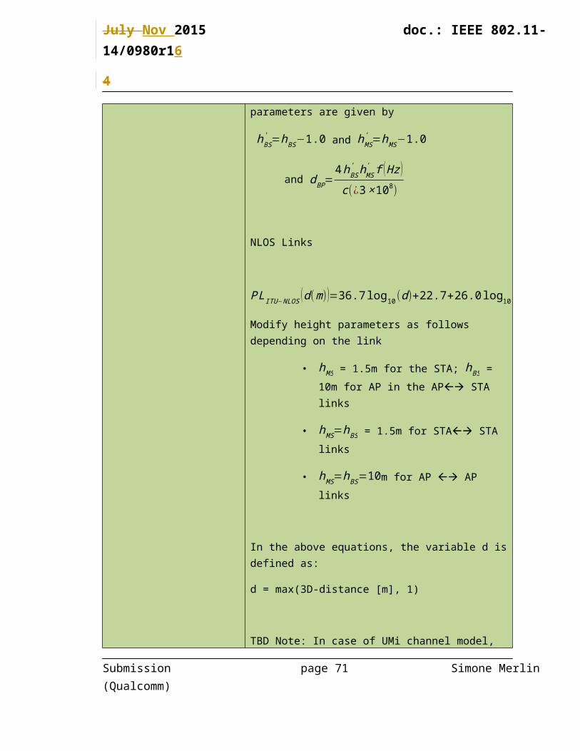
P LITU −LOS ( d (m )>dBP )=40 log10(d>dBP)+7.8−18 log10 (hBS' )−18 log10 (hMS
' )+2 log10 f c (GHz)
where the effective antenna height parameters are given by
hBS' =hBS−1.0 and hMS
' =hMS−1.0
and d BP=4hBS
' hMS' f ( Hz )
c (¿3×10⁸)
NLOS Links
P LITU−NLOS ( d (m))=36.7 log10(d )+22.7+26.0 log10 f c (GHz )
Submission page 52 Simone Merlin (Qualcomm)

July Nov 2015 doc.: IEEE 802.11-14/0980r1
4
Modify height parameters as follows depending on the link
• hMS = 1.5m for the STA; hBS = 10m for AP in the AP STA links
• hMS=hBS = 1.5m for STA STA links
• hMS=hBS=10m for AP AP links
In the above equations, the variable d is defined as:
d = max(3D-distance [m], 1)
TBD Note: In case of UMi channel model, M.2135-1 defines that 50% of user are indoor users, but since indoor users can be served by indoor AP, we can change the percentage of users are indoor; need to decide which percentage
Penetration Losses None
PHY parameters
MCS [use MCS0 for all transmissions] or
[use MCS7 for all transmissions]
GI Long
AP #of TX antennas All APs with [2] or all APs with 4
AP #of RX antennas All APs with [2] or all APs with 4
STA #of TX antennas All STAs with [1] or all STAs with 2
STA #of RX antennas All STAs with [1] or all STAs with 2
MAC parameters
Access protocol parameters [EDCA with default EDCA Parameters set]
Submission page 53 Simone Merlin (Qualcomm)

July Nov 2015 doc.: IEEE 802.11-14/0980r1
4
Center frequency, BW and
primary channels
Frequency reuse 1 is used.
5GHz
all BSSs are using the same 80MHz channel
[Same Primary channel]
2.4GHz
All BSSs are 20MHz BSS on same channel
Aggregation [A-MPDU / max aggregation size / BA window size, No A-MSDU, with immediate BA]
Max # of retries 10
RTS/CTS Threshold [no RTS/CTS]
Association X% of STAs are associated with the strongest AP, Y% of STAs are associated with the second-strongest AP, and Z% of STAs are associated with the third-strongest AP. Z% of STAs are not associated. Detailed distribution to be decided.
[X=100, Y=0,Z=0]
Management It is allowed to assume that all APs belong to the same management entity
Submission page 54 Simone Merlin (Qualcomm)

July Nov 2015 doc.: IEEE 802.11-14/0980r1
4
Submission page 55 Simone Merlin (Qualcomm)

July Nov 2015 doc.: IEEE 802.11-14/0980r1
4
Traffic model for each BSS
Sim Traffic Identifier
Source/Sink Traffic Model1 Traffic Model Class Identifier2
Directional3 Number of Traffic
Services Assigned to STAs in Sim Population
(Source/Sink)4
AC
D1 AP/STA Buffered Video Streaming
BV6 Asymmetric Bi-directional
5/5 VI
D2 AP/STA Buffered Video Streaming
BV3 Asymmetric Bi-directional
20/20 VI
D3 AP/STA Multicast Video Streaming
MC2 Unidirectional 1/12 VI
D4 AP/STA FTP FTP Asymmetric Bi-directional
4/4 BE
D5 AP/STA HTTP HTTP Asymmetric Bi-directional
15/15 BE
D6 AP/STA Gaming GMG Asymmetric Bi-directional
25/25 VI
D7 AP/STA VoIP VOIP Symmetric Bi-directional
20/20 VO
D8 AP/STA MGMT: Beacon
280 octets long Beacon frame @ 1 Mbps in 2.4 GHz/
@ 6 Mbps in 5 GHz is transmitted
every 100 TUs
Unidirectional 1/0 VI
U1 STA/AP Buffered Video Streaming
BV3 Asymmetric Bi-directional
10/10 VI
U2 STA/AP FTP FTP Asymmetric Bi-directional
4/4 BE
U3 STA/AP Gaming GMG Asymmetric 25/25 VI
Submission page 56 Simone Merlin (Qualcomm)

July Nov 2015 doc.: IEEE 802.11-14/0980r1
4
Bi-directional
U4 STA/AP MGMT: Probe Req
TBD Unidirectional All unassociated
STAs/0
VI
Note 1,2,3: From Evaluation Methodology Document Appendix 2, except for MGMT traffic types which are defined in the Table.
Note 4: Traffic Services to/from STAs shall be randomly assigned among the total number of STAs in the simulation population for the identified population granularity (apartment, office cubicle, BSS, etc…). For example, the Traffic Service D1 would be randomly assigned to five different STAs, for SS4 that would be 5 of 50 STAs. Assignment to AP is always to a single AP in the simulation population for the identified population granularity.
4a- Outdoor Large BSS + Residential Scenario
Parameter Value
Topology (A)
Submission page 57 Simone Merlin (Qualcomm)

July Nov 2015 doc.: IEEE 802.11-14/0980r1
4
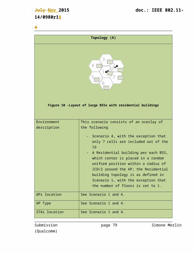
Figure 10 –Layout of large BSSs with residential buildings
Environment description This scenario consists of an overlay of the following
- Scenario 4, with the exception that only 7 cells are included out of the 19
- A Residential building per each BSS, which center is placed in a random uniform position within a radius of ICD/2 around the AP; the Residential building topology is as defined in Scenario 1, with the exception that the number of floors is set to 1.
APs location See Scenario 1 and 4.
AP Type See Scenario 1 and 4.
STAs location See Scenario 1 and 4.
Number of STA and STAs type
See Scenario 1 and 4.
Channel Model See Scenario 1 and 4
{indoor/outdoor??}
Penetration Losses See Scenario 1 and 4.
PHY parameters
Same parameters as defined for the STAs in Scenario 1 and Scenario 4.
Submission page 58 Simone Merlin (Qualcomm)

July Nov 2015 doc.: IEEE 802.11-14/0980r1
4
MAC parameters
All parameters except the ones listed in this table are same as in Scenario 1 and Scenario 4
Association STAs defined by Scenario 1, associate as defined by Scenario 1
STAs defined by Scenario 4:
80% associate as defined by Scenario 4
20% associate with strongest AP from a Residential building
Management It is allowed to assume that all outdoor APs belong to the same management entity. Each indoor AP belongs to a different management entity
Traffic model (Per each BSS) - TBD
# Source/Sink NameTraffic definition Flow specific parameters AC
Downlink
Traffic model for STAs defined by Scenario 1, is defined by Scenario 1
Traffic model for STAs defined by Scenario 2, is defined by Scenario 2
Scenarios for calibration of MAC simulator
The applicability of each test in this section is TBD.
Common parameters
PHY Parameter SUGGESTED VALUES
Submission page 59 Simone Merlin (Qualcomm)

July Nov 2015 doc.: IEEE 802.11-14/0980r1
4
GI: [long]
Data Preamble: [11ac]
BW 20 Mhz
The following parameters are common to the MAC tests unless otherwise stated.
Parameter SUGGESTED VALUES
Aggregation A-MPDU
max aggregation size =64
No A-MSDU
immediate BA
(aggregation is assumed to be ON)
Max number of retries 10
Rate adaptation Fixed MCS
EDCA parameters Default params for best effort (CWmin=15)
AIFSN=3
The follwing parameters are common to the traffic model unless otherwise stated.
Transpot protocol- UDP
Traffic model: full buffer
Submission page 60 Simone Merlin (Qualcomm)

July Nov 2015 doc.: IEEE 802.11-14/0980r1
4
Test 1a: MAC overhead w/out RTS/CTS
Goal:
designed to verify whether the simulator can correctly handle the basic frame exchange procedure, including AIFS+backoff procedure and A-MPDU+SIFS+BA sequence. Also to make sure the overheads are computed correctly.
Assumptions:
Assumption is that PER is 0
Parameters:
MSDU length:[0:500:2000Bytes]
2 MPDU limit
RTS/CTS off
Data MCS = [0,8] ( to clarify, run a sweep over MSDU length once for MCS 0, and once for MCS 8.
Block ACK MCS=0 (non-HT format)
Submission page 61 Simone Merlin (Qualcomm)
AP1STA 1

July Nov 2015 doc.: IEEE 802.11-14/0980r1
4
AIFS=DIFS=34us
Output metric:
(1) MAC layer Throughput
(2) Time trace of transmitting/Receiving event
CP1 ( check point 1) start of A-MPDU
CP2 end of A-MPDU
CP3 start of Block ACK
CP4 end of Block ACK
CP5 start of A-MPDU
Test Items Check points Standard definition Matching?
A-MPDU duration
Tcp2-Tcp1= ceil((FrameLength*8)/rate/OFDMsymbolduration) * OFDMsymbolduration + PHY Header
SIFS Tcp3-Tcp2=16 us 16 us
Block ACK duration
Tcp4-Tcp3= ceil((ACKFrameLength*8)/rate/OFDMsymbolduration) * OFDMsymbolduration + PHY Header
Defer & backoff duration
Tcp5-Tcp4= DIFS(34 us)+backoff (CWmin)=34us+n*9us
Submission page 62 Simone Merlin (Qualcomm)

July Nov 2015 doc.: IEEE 802.11-14/0980r1
4
Tcp is the timestamp related with the corresponding simulation event on the check point (CP)
The following is an example calcultation of TPUT when the MSDU size is 1508, and MCS =0
Number of MPDUs in AMPDU= 2 Bytes per MPDU: 1538
o Bytes from application laye:1472o The MSDU size is 1508
28-bytes UDP/IP header and 8 byte LLC packet header So total of 36 bytes are to added to the application packet, making
1508 byte of MSDU sizeo MAC header 30 byteso FC=2;Duration=2;Addr1=6;Addr2=6;Addr3=6;SeqContrl=2;QoSCntrl=2;
FCS=4 Note: Assuming HT control field is not used
o MPDU delimiter 4 bytes in each AMPDU subframeo 2 bytes padding in first MPDU
Bytes per PSDU: 2*(1538+4+2)=3088B Each PSDU is appended with:
o Tail bits 6 bitso Service Field 2 Bytes
Total bits per PPDU without preamble (i.e, data field in PPDU): 3088*8+6=24726 bits
Duration of PPDU w/out preamble= ceil(24726/26)*4us =3.804ms Duration of PPDU w/ preamble= 3.844ms Duration of Block ACK 68 us Expected time waiting for the Medium = 110.5 us
(SIFS+AIFSN*slotTime+CW/2*slotTime=16+3*9+15/2*9) Expected TPUT= 1472*8*2/(3.844ms+68us+16us+110.5us) =5.83Mbps (Note this is application layer tput)
Submission page 63 Simone Merlin (Qualcomm)

July Nov 2015 doc.: IEEE 802.11-14/0980r1
4
Note: in some simulators, there may be management frame exchanges such as ABBBA request/response and the corresponding ACKs before application data transmission, which may slightly affect the simulation results.
Test 1b: MAC overhead w RTS/CTS
Goal:
This test case is designed to further verify whether the simulator can correctly handle the frame exchange procedure with RTS/CTS protection based on test1a. It also tests whether the correct overhead computation with RTS /CTS.
Assumptions:
Assumption is that PER is 0
Parameters:
MSDU length:[0:500:2000Bytes]
2 MPDU limit
RTS/CTS ON
Data MCS = [0,8] ( to clarify, run a sweep over MSDU length once for MCS 0, and once for MCS 8.
Submission page 64 Simone Merlin (Qualcomm)
AP1STA 1

July Nov 2015 doc.: IEEE 802.11-14/0980r1
4
RTS/CTS MCS=0
ACK MCS=0
AIFS=DIFS=34us
Output metric:
(1) MAC layer Throughput (2) Time trace of transmitting/Receiving event
CP1 ( check point 1) : start of RTS
CP2 : end of RTS
CP3: start of CTS
CP4: end of CTS
CP5: start of A-MPDU
CP6: end of A-MPDU
Test Items Check points Standard definition Matching?
Submission page 65 Simone Merlin (Qualcomm)

July Nov 2015 doc.: IEEE 802.11-14/0980r1
4
RTS duration Tcp2-Tcp1= ceil((RTSFrameLength*8)/rate/OFDMsymbolduration) * OFDMsymbolduration + PHY Header
CTS duration Tcp4-Tcp3= ceil((CTSFrameLength*8)/rate/OFDMsymbolduration) * OFDMsymbolduration + PHY Header
Frame duration
Tcp6-Tcp5= ceil((FrameLength*8)/rate/OFDMsymbolduration) * OFDMsymbolduration + PHY Header
The following is an example TPUT calculation when MSDU size is 1508, and MCS =0
Number of MPDUs in AMPDU= 2 Bytes per MPDU:
o Bytes from application layer:1472o L4 header: 36 byteso MAC header 30 byteso FC=2;Duration=2;Addr1=6;Addr2=6;Addr3=6;SeqContrl=2;QoSCntrl=2;
FCS=4o MPDU delimiter 4 byteso 2 bytes padding
Bytes per AMPDUo Tail bits < 1 byteso Service Field 2 Bytes
Total Bytes per AMPDU: 3091 Duration of PPDU w/out preamble= 3091/6.5e6=3.804ms Duration of PPDU w/ preamble= 3.844ms Duration of ACK 68 us Duration of RTS 52 us Duration of CTS 44 us SIFS= 16us Expected time waiting for the Medium = 100.5 us (CWmin =15) Expected TPUT= 1472*8*2/(3.844ms+68us+16us+100.5us +
52us+44us+2*16us) (Note this is application layer TPUT)
Submission page 66 Simone Merlin (Qualcomm)

July Nov 2015 doc.: IEEE 802.11-14/0980r1
4
Test 2a: Deferral Test 1
Goal:
This test case is designed to verify whether the simulator can correctly handle deferral procedure after collision happens without hidden nodes. It also checks whether deferral because of energy levels is happening correctly.
Assumptions:
All devices are within energy detect range of each other.
When AP1 and AP2 start to transmit on the same slot, both packets are lost (PER= 100%). Otherwise packets get through 100%. PER=0 %
Note:
AP1 and AP2 should defer to each other.
The only packet loss is due to collisions when backoffs end at same time
Submission page 67 Simone Merlin (Qualcomm)
(AP1 and STA2 are essentially co-located)
STA 2
AP1 AP 2
STA 1

July Nov 2015 doc.: IEEE 802.11-14/0980r1
4
Parameters:
MSDU length:[0:500:2000Bytes]
2 MPDU limit
RTS/CTS [ OFF, ON]
Data MCS = [0]
RTS/CTS MCS=0
ACK MCS=0
AIFS=DIFS=34us
CWmax=1023
Outputs:
MAC tput.
Test 2b: Deferral Test 2
Goal:
Submission page 68 Simone Merlin (Qualcomm)
STA 2
AP1
AP 2
STA 1

July Nov 2015 doc.: IEEE 802.11-14/0980r1
4
This test case is designed to verify whether the simulator can correctly handle deferral procedure after collision happens with the existing of hidden nodes.
Assumptions:
AP1 and AP2 can not hear each other ; i.e they are not within Preamble detection range of each .
– Interference Assumptions:
• If any part of an MPDU sees interference, that MPDU should fail
• If any part of a data preamble sees interference, all MPDUs should fail
• If an MPDU, or data premable sees no interference, it should pass
• If an ACK overlaps with the transmission of an OBSS AP, the PER on the ACK should be 0. (i.e. the ACK should pass)
– Backoff
• If no ACK is received, the transmitter should double it’s CW.
• If an ACK is received, the transmitter should reset its CW
• If no MPDUs are decoded, no ACK should be sent.
• After 10 missing ACKS, the CW should be reset.
– PER definition
• PER= 1-Acked data MPDUs/Total data MPDUs sent
– ( TPUT can be computed from number of successfully ACKed MPDUs and the total time)
ACKed data MPDUs are measured by the transmitters
Parameters:Submission page 69 Simone Merlin (Qualcomm)

July Nov 2015 doc.: IEEE 802.11-14/0980r1
4
MSDU length:[1500Bytes]
RTS/CTS [ OFF]
Data MCS = [0,8]
ACK MCS=0
AIFS=DIFS=34us
CWmax=1023
2MPDU limit
Outputs:
MAC tput.
Test 3: NAV deferral
Same as test 2b, but with RTS/CTS on.
ACK MCS=0
RTS/CTS MCS=0
AIFS=DIFS=34usSubmission page 70 Simone Merlin (Qualcomm)
STA 2
AP1
AP 2
STA 1
July Nov 2015 doc.: IEEE 802.11-14/0980r1
4
CWmax=1023
2MPDU limit
Goal: This test is designed to test whether NAV deferral is happening properly.
Test 4: Deferral Test for 20 and 40MHz BSSs
Assumptions:
All devices are within energy detect range of each other.
Data PPDU is transmitted in VHT format, while RTS and CTS PPDUs are transmitted in non-HT duplicate format.
When AP1 and AP2 start to transmit on the same slot, both packets are lost (PER= 100%). Otherwise packets get through 100%. PER=0 %
Submission page 71 Simone Merlin (Qualcomm)
(AP1 and STA2 are essentially co-located)
STA 2
AP1 AP 2
STA 1

July Nov 2015 doc.: IEEE 802.11-14/0980r1
4
A non-HT duplicate PPDU can be successfully received by a STA if there is no other signal appearing in the STA’s primary channel within the PPDU duration.
If RTSs transmitted by AP1 and AP2 collide, AP1 obtains a TXOP only in primary channel. The AP2 does not obtain TXOP.
Note:
AP1 and AP2 should defer to each other.
The only packet loss is due to collisions when backoffs periods of AP1 and AP2 end at the same time
Parameters:
MSDU length:[ 2000Bytes]
RTS/CTS [ OFF, ON]
MCS = [0]
Procedure:
AP1 sends traffic to STA1 on a 40MHz channel with a full buffer continuously.. All other setting is the same as test case 2a.
AP2 sends traffic to STA2 on a 20MHz channel staing at t1, which is located at the secondary channel of BSS1.
The traffic is based on the Poisson distribution with following parameters.
– MSDU length at 2000Bytes.
– Let lambda, for example, to be 100 ( in the unit of 1/second)
• The mean inter-arrival time is 1/100 second. Submission page 72 Simone Merlin (Qualcomm)

July Nov 2015 doc.: IEEE 802.11-14/0980r1
4
The long time average data rate for the largest MSDU size is 2000*8/(1/100)=1.6Mbps
1.6 Mbps is non-full buffer traffic since it is lower than the 20MHz BSS MCS0 rate
Implementing Traffic Generator
For vendor with proprietary simulator, Poisson distribution traffic generator is a vendor specific implementation.
How to determine the simulation time for a simulator
Each simulator calibrates its running time o Step 1: Activating the 20MHz BSS only and monitoring how long it will
take for the throughput of the 20MHz BSS to be stabilized. Recording the time, t.
o The throughput of the 20MHz BSS shall corresponding to the mean “inter arrival time”.
Step 2: Run the OBSS MAC calibration case for at least time t.
If any packet is transmitted at the overlapping time with another one and on the overlapping channel, both transmissions are considered failure(PER = 1).
Measure the throughput of AP1, AP2, STA1 and STA2. Also measure the percentage of time of the each of the bandwidth specific Power states of the APs. Listen state is not bandwidth specific whereas Receive and Transmit states are bandwidth specific.
Outputs:
MAC tput.
Percentages of time of the each of the bandwidth specific Power states of AP. The results are obtained for both AP1 and AP2.
Submission page 73 Simone Merlin (Qualcomm)

July Nov 2015 doc.: IEEE 802.11-14/0980r1
4
The following example shows how occupations on 20MHz and 40MHz are calculated for AP1 in case when AP1 transmits once using 20MHz and once using 40MHz.
CTS
LI
MPDUMPDU
RTSPrimary
Secondary
T120MHz
T320MHz
T220MHz
RTS
RTS
CTS CTS
T540MHz
T740MHz
T640MHz
TX_Percentage_20MHz = 100 × (T1+T3)/Simulation_timeRX_Percentage_20MHz = 100 × (T2+T4)/Simulation_timeTX_Percentage_40MHz = 100 × (T5+T7)/Simulation_timeRX_Percentage_40MHz = 100 × (T6+T8)/Simulation_timeListen_Percentage = 100 × Listen_time/Simulation_time
ACKACK
T420MHz
T840MHz
TX RX TX RXPower states at AP1 TX RX TX RXLI LI
Transmit (TX)
Receive (RX)
Listen (LI)Simulation_time
Test 5: Power Save Mechanism Test
Goal:
This test case is intended to verify the baseline power save mechanism implemented in MAC system simulator
Assumptions:
PER = 0
PSM test:
Submission page 74 Simone Merlin (Qualcomm)
STA AP

July Nov 2015 doc.: IEEE 802.11-14/0980r1
4
Figure 11 – Example of the frameflow in PSM scenario and non-AP STA Power States.
•MSDU length: 1500 bytes with CWmin=15 downlink every 200 ms
•RTS/CTS [ OFF ]
•AIFS=DIFS=34us
•MCS = [ 0 ]
•No A-MPDU aggregation
•Beacon is 80 octets long Beacon frame (as defined in the Traffic model)
•When a STA in PS mode wakes for DTIM Beacon and detects that the TIM bit corresponding to its AID is set to 0, STA returns to Shallow Sleep state. STA remains in Shallow Sleep state until the next DTIM Beacon.
•DTIM = [ 3 ]
•PSM timeout = [ 100 ] ms
PSP test:
Submission page 75 Simone Merlin (Qualcomm)

July Nov 2015 doc.: IEEE 802.11-14/0980r1
4
Figure 12 – Example of the frameflow in PSP scenario and non-AP STA Power States.
MSDU length: 1500 bytes with CWmin=15 downlink every 200 ms
•RTS/CTS [ OFF ]
•AIFS=DIFS=34us
•MCS = [ 0 ]
•No A-MPDU aggregation
•Beacon is 80 octets long Beacon frame (as defined in the Traffic model)
•When a STA in PS mode wakes for DTIM Beacon and detects that the TIM bit corresponding to its AID is set to 0, STA returns to Shallow Sleep state. STA remains in Shallow Sleep state until the next DTIM Beacon.
•DTIM = [ 3 ]
U-APSD test
Submission page 76 Simone Merlin (Qualcomm)

July Nov 2015 doc.: IEEE 802.11-14/0980r1
4
Figure 13 – Example of the frameflow and backoff in U-APSD scenario and non-AP STA Power fStates.
MSDU length: 120 bytes with CWmin=15 (once every 40 ms) for both uplink and downlink
Power save test parameters
AIFS=DIFS=34us RTS/CTS [ OFF ] MCS = [ 0 ] Beacon is not transmitted in U-APSD test Max SP Length = [ 4 ] ProbeDelay = 100µs
A STA that is changing from Doze to Awake in order to transmit shall perform CCA until a frame sequence is detected by which it can correctly set its NAV, or until a period of time equal to the ProbeDelay has transpired. If no valid NAV has been set during the period of ProbeDelay, the STA shall perform the Basic Access procedure as defined in 9.3.4.2 (Basic access) immediately after ProbeDelay’s transpiration.
Submission page 77 Simone Merlin (Qualcomm)
July Nov 2015 doc.: IEEE 802.11-14/0980r1
4
Output:
MAC throughput
Table (breakdown) of percentage of time spent in each power state during the course of the simulation
STA (%) AP (%)
Listen RX TX Shallow Sleep Listen RX TX Shallow
Sleep
< Power Save
Mechanism > On
< Power Save
Mechanism > Off
Pie chart (breakdown) of energy consumed in each power state during the course of the simulation
STA (Watt) AP (Watt)
Listen RX TX Shallow Sleep Listen RX TX Shallow
Sleep
< Power Save
Mechanism > On
Submission page 78 Simone Merlin (Qualcomm)
July Nov 2015 doc.: IEEE 802.11-14/0980r1
4
< Power Save
Mechanism > Off
Scenario s for calibration of Box5 simulator
As shown in Table 2 of 11-14/0571, scenarios 1 and 4 are used for Box5 calibration. Besides, 11ac scenario 6 [11-09/0451r16] is suggested to be used for initial and quick calibration.
Common parameters
The basic procedure of packet reception and preamble detection is defined in the appendix 4 of 11-14/0571r8 which is simplified specifically for Box5 calibration in the subsection “Box 5” of section “System Simulation Calibration”
PHY parameters
BW All BSSs at 5GHz [80 MHz, no dynamic bandwidth]
Primary channel
Aligned primary 20MHz channel for each co-
80MHz-channel BSS;
The detection of preamble and BA should only focus on primary 20MHz
Channel model TGac D NLOS per link
Shadow fading iid log-normal shadowing (5 or 0 dB standard deviation) per link
Preamble Type Control: legacy 20us; Data: 11ac (20us+20us for
Submission page 79 Simone Merlin (Qualcomm)

July Nov 2015 doc.: IEEE 802.11-14/0980r1
4
1antenna case)
AP/STA TX Power 20/15 dBm per antenna
Power Spectral density Scaled to 80 MHz
number of antennas at AP /STA 1/1
AP /STA antenna gain 0/-2 dBi
Noise Figure 7dB
CCA-ED threshold -56 dBm (measured across the entire bandwidth after large-scale fading)
Rx sensitivity/CCA-SD -76 dBm (a packet with lower rx power is dropped)
Link AdaptionFixed MCS =5 for 11ac SS6 and TBD for 11ax SS1-4
Channel estimation Ideal unless otherwise specified
PHY abstraction RBIR, BCC [ 2, 9]
Symbol length 4us with 800ns GI per OFDM symbol
MAC parameters
Access protocol [EDCA, AC_BE with default parameters] [CWmin = 15,
CWmax = 1023, AIFSn=3 ]
Queue lengthA single queue for each traffic link is set inside AP/STA
sized of 2000 packets
Traffic type
UDP CBR with rate 10^8bps (may not enough to model
full buffer)
Random start time during a 10ms interval
Submission page 80 Simone Merlin (Qualcomm)

July Nov 2015 doc.: IEEE 802.11-14/0980r1
4
MPDU size1544 Bytes (1472 Data + 28 IP header + 8 LLC header +
30 MAC header + 4 delimiter + 2 padding)
Aggregation [A-MPDU / max aggregation size / BA window size, No A-MSDU, with immediate BA], Max aggregation: 32 or 64 MPDUs
Max number of
retries 10
Beacon Disabled unless otherwise specified
RTS/CTS OFF unless otherwise specified
Running time >= 10s per drop
Output metric
-CDF or Histogram of per non-AP STA throughput
(received bits/overall simulation time)
-PER of all AP/STA (1 - # of success subframes / # of
transmitted subframes)
Test Cases of 11ac Scenario 6
No shadowing is assumed.
• 1 BSS (upper-right corner BSS B)
– DL only case
– UL only case
• 1 STA: each STA-AP
• 2 STAs: 3+9, 3+15, 3+27
• 3 STAs: 3+9+15, 3+9+27
– DL & UL case
• 2 BSS (A+B)
Submission page 81 Simone Merlin (Qualcomm)

July Nov 2015 doc.: IEEE 802.11-14/0980r1
4
– Both DL only
– Both UL only
– A DL and B UL
– B UL and A DL
• 3 BSS
– DL only
– UL only
– Mixed DL & UL
Calibration results
The initial calibration report is provided in contribution 14/1192r6
Submission page 82 Simone Merlin (Qualcomm)

July Nov 2015 doc.: IEEE 802.11-14/0980r1
4
Submission page 83 Simone Merlin (Qualcomm)
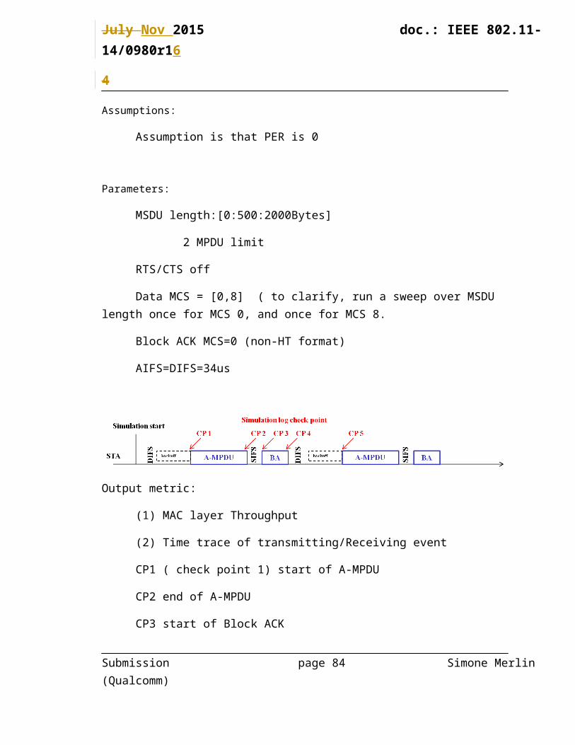
July Nov 2015 doc.: IEEE 802.11-14/0980r1
4
Annex 3 - Templates
Parameter Value
Topology
Figures
Environment description
APs location
AP Type
STAs location
Number of STA and STAs type
Channel Model
Penetration Losses
PHY parameters
Center frequency and BW
MCS
GI
Data Preamble:
STA TX power
AP TX Power
AP #of TX antennas
Submission page 84 Simone Merlin (Qualcomm)

July Nov 2015 doc.: IEEE 802.11-14/0980r1
4
AP #of RX antennas
STA #of TX antennas
STA #of RX antennas
MAC parameters
Access protocol parameters
Primary channels
Aggregation
Max # of retries
RTS/CTS Threshold
Association
References
May 2013
1. 11-13/486, “Evaluation methodology and simulation scenarios” Ron Porat (Broadcom)
2. 11-13/520r1, HEW Scenarios and Evaluation Metrics, Thomas Derham (Orange)
3. 11-13/538 “Dense apartment building use case for HEW” , Klaus Doppler (Nokia)
4. 11-13/ 542 “Discussion on scenarios and goals for HEW”, Simone Merlin (Qualcomm)
July 2013
5. 11-13/0657r6 HEW SG usage models and requirements - Liaison with WFA Laurent Cariou (Orange)
Submission page 85 Simone Merlin (Qualcomm)
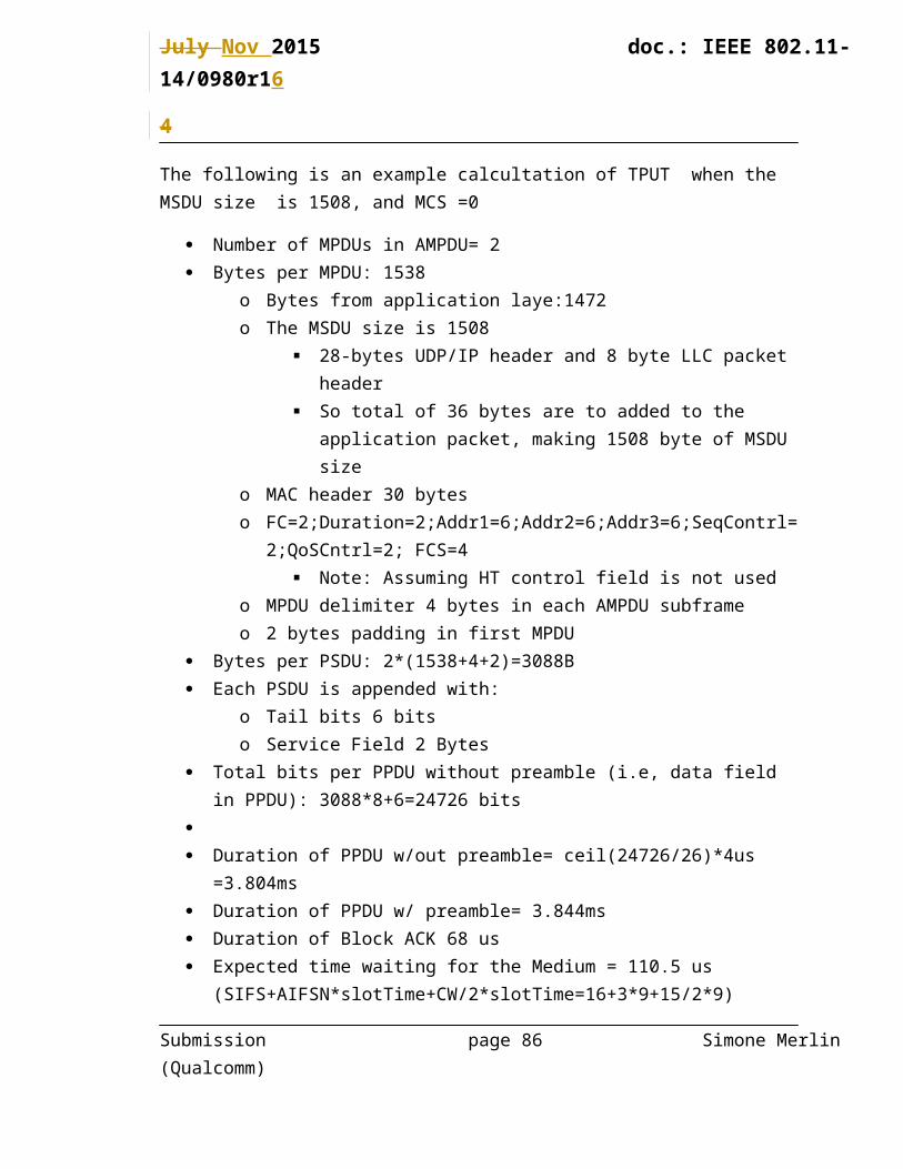
July Nov 2015 doc.: IEEE 802.11-14/0980r1
4
6. 11-13/0722r1, “HEW Evaluation Methodology”, Minyoung Park (Intel)
7. 11-13/0723, “HEW SG evaluation methodology overview” Minyoung Park (Intel)
8. 11-13/757, “Evaluation methodology and simulation scenarios” Ron Porat (Broadcom)
9. 11-13/0786, “HEW SLS methodology”, Tianyu Wu (Huawei)
10. 11-13/0795, “Usage scenarios categorization”, Eldad Perahia (Intel)
11. 11-13/0800, “HEW Study Group Documentation”, Hemanth Sampath (Qualcomm)
12. 11-13/0802, “Proposed re-categorization of HEW usage Models”, Yasuhiko Inoue (NTT)
13. 11-13/0847, “Evaluation Criteria and Simulation Scenarios”, Klaus Doppler (Nokia)
14. 11-13/869r0, Simulation scenarios and metrics for HEW, Thomas Derham (Orange
September 2013
15. 11-13/1000r2 Simulation Scenarios, Simone Merlin (Qualcomm)16. 11-13/1083r0 HEW SG Unified Simulation Scenarios, David Xun Yang (Huawei)17. 11-13/1079r0 Outdoor Stadium Simulation Details Discussion, Joseph Levy
(InterDigital)18. 11-13/1081 HEW Simulation Methodology, Sayantan Choudhury (Nokia)19. 11-13/1114 Simulation scenario for unplanned Wi-Fi network, Minho Cheong
(ETRI)20. 11-13/1153 Simulation scenario proposal, Laurent Cariou (Orange)21. 11-13/1176r0 Some Simulation Scenarios for HEW, Reza Hedayat (Cisco Systems)22. 11-13/1248r0 Simulation scenario - Contribution 1153 on dense hotspot and outdoor
large BSS, Laurent Cariou (Orange)
November 2013
23. 11-13/1305, Traffic Simulation Simplifications, William Carney (SONY)
24. 11-13/1334/5, Video Traffic Modeling--word with details, Guoqing Li (Intel)
25. 11-13/1383 System Level Simulation Parameters, Wookbong Lee (LGE)
26. 11-13/1392 Methodology of calibrating system simulation results Yan Zhang (Marvell)
JanuARY 2014
11-14/0051R0 Wireless Office with Interference, David Yangxun (Huawei)
Submission page 86 Simone Merlin (Qualcomm)
July Nov 2015 doc.: IEEE 802.11-14/0980r1
4
27. 11-14-0627-00-00ax-outdoor-models-for-system-level-simulations.pptx
September 2014
23. 11-14-1161-03-00ax-parameters-for-power-save-mechanisms, Eric Wong (Apple)24. 11-14-1162-01-00ax-energy-efficiency-evaluation-methodology-follow-up, Eric
Wong (Apple)
November 2014
11-14-1496-05 Power-Save-Calibration-Scenario, Jarkko Kneckt (Nokia)
January 2015
25. 11-15-0172-01-00ax-proposed-text-to-tgax-simulation-scenarios-u-apsd-test Guoqing Li, (Apple)
26. 11-15-0061-06-00ax-fps-network-traffic-model, Allan Jones (Activision)27. 11-15-0172-01-00ax-proposed-text-to-tgax-simulation-scenarios-u-apsd-test, Yanchun Li
(Huawei)
May 2015
11-15-0373-04-00ax-mixed-traffic-configurations-on-simulation-scenarios.docx
11-15-0576-02-00ax-power_latency_state_transitions.pptx
11-15-0681-00-00ax-proposed-text-additions-to-14-980-for-box5-calibration.docx
Submission page 87 Simone Merlin (Qualcomm)


![= N/#11N GJ= J77 ]](https://img.dokumen.tips/doc/110x75/5e8e5fc7b12190665911d57c/-n11n-gj-j77-.jpg)


