Embed Size (px)
Citation preview

November 2006
C. Wright, Azimuth Systems
Slide 1
doc.: IEEE 802.11-06/1839r1
Submission
MIMO Testing In A Conducted Environment
Notice: This document has been prepared to assist IEEE 802.11. It is offered as a basis for discussion and is not binding on the contributing individual(s) or organization(s). The material in this document is subject to change in form and content after further study. The contributor(s) reserve(s) the right to add, amend or withdraw material contained herein.
Release: The contributor grants a free, irrevocable license to the IEEE to incorporate material contained in this contribution, and any modifications thereof, in the creation of an IEEE Standards publication; to copyright in the IEEE’s name any IEEE Standards publication even though it may include portions of this contribution; and at the IEEE’s sole discretion to permit others to reproduce in whole or in part the resulting IEEE Standards publication. The contributor also acknowledges and accepts that this contribution may be made public by IEEE 802.11.
Patent Policy and Procedures: The contributor is familiar with the IEEE 802 Patent Policy and Procedures <http:// ieee802.org/guides/bylaws/sb-bylaws.pdf>, including the statement "IEEE standards may include the known use of patent(s), including patent applications, provided the IEEE receives assurance from the patent holder or applicant with respect to patents essential for compliance with both mandatory and optional portions of the standard." Early disclosure to the Working Group of patent information that might be relevant to the standard is essential to reduce the possibility for delays in the development process and increase the likelihood that the draft publication will be approved for publication. Please notify the Chair <[email protected]> as early as possible, in written or electronic form, if patented technology (or technology under patent application) might be incorporated into a draft standard being developed within the IEEE 802.11 Working Group. If you have questions, contact the IEEE Patent Committee Administrator at <[email protected]>.
Date: 2006-11-10
Name Company Address Phone email Charles R. Wright
Azimuth Systems
31 Nagog Park, Acton MA 01890
978-268-9202 charles_wright@ azimuthsystems.com
Authors:

November 2006
C. Wright, Azimuth Systems
Slide 2
doc.: IEEE 802.11-06/1839r1
Submission
Abstract
This presentation describes how to augment the TGT conducted environment to measure the performance of MIMO WLAN systems with and without the presence of simulated multipath conditions.

November 2006
C. Wright, Azimuth Systems
Slide 3
doc.: IEEE 802.11-06/1839r1
Submission
Summary
• Multipath is an important factor influencing the performance of WLANs
• Also, MIMO systems present some interesting challenges to conducted testing– How do you cable together two MIMO systems?
• The current TGT draft does not contain any recommendations on how to make repeatable tests of WLAN devices in the presence of multipath
• This proposal contains– A recommendation that the TGn channel models be used as the
baseline channels– A description of a conducted test environment for measuring
multipath performance of two WLAN devices
November 2006
C. Wright, Azimuth Systems
Slide 4
doc.: IEEE 802.11-06/1839r1
Submission
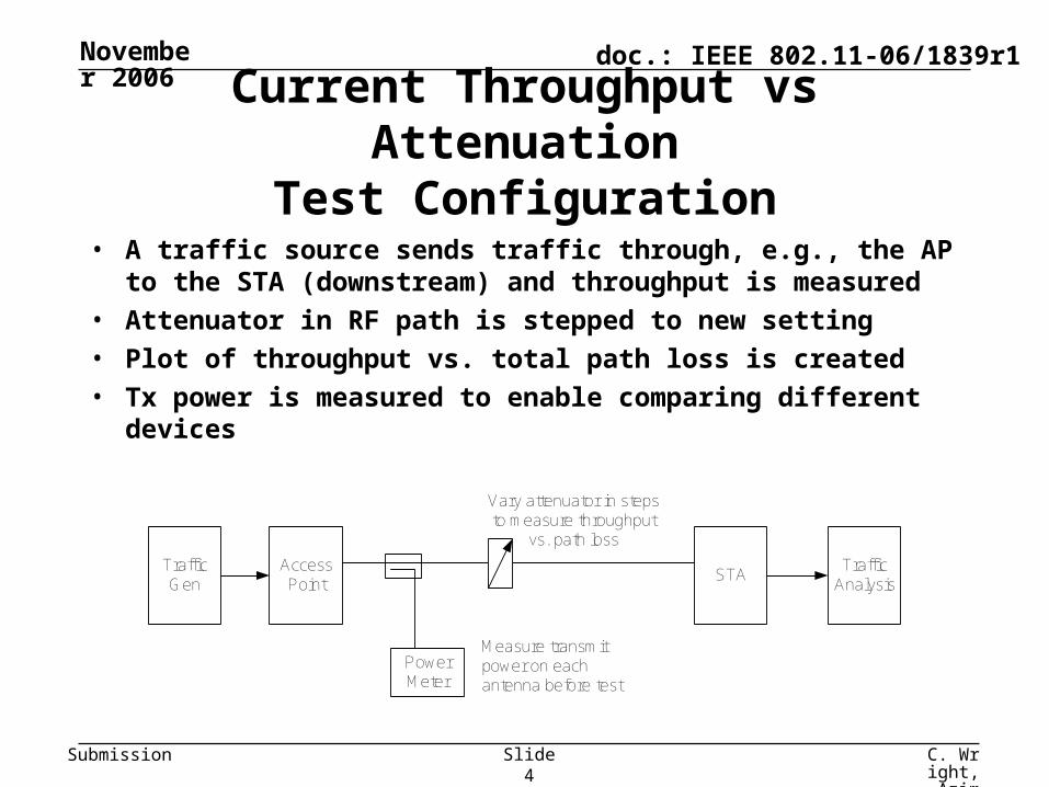
Current Throughput vs AttenuationTest Configuration
• A traffic source sends traffic through, e.g., the AP to the STA (downstream) and throughput is measured
• Attenuator in RF path is stepped to new setting
• Plot of throughput vs. total path loss is created
• Tx power is measured to enable comparing different devices
AccessPoint
STA
PowerMeter
TrafficGen
TrafficAnalysis
Measure transmitpower on eachantenna before test
Vary attenuator in stepsto measure throughput
vs. path loss

November 2006
C. Wright, Azimuth Systems
Slide 5
doc.: IEEE 802.11-06/1839r1
Submission
MIMO version of Throughput vs Attenuation
• Traffic generator and analyzer required, as usual• Need to have up to 4 controllable attenuators
– Assuming 4x4 MIMO is maximum
• A MIMO channel is introduced– More to come on next slide
• Otherwise same procedure and same set of results
AccessPoint
STA
PowerMeter
TrafficGen
TrafficAnalysis
Measure transmitpower on eachantenna before test
Vary attenuators in stepsto measure throughput
vs. path loss
MIMOChannel,
H(x4)

November 2006
C. Wright, Azimuth Systems
Slide 6
doc.: IEEE 802.11-06/1839r1
Submission
Possible Choices for MIMO Channel, H
• Fixed channels– Identity matrix
– Butler matrix
– Other
• Time-varying channels– TGn channel models

November 2006
C. Wright, Azimuth Systems
Slide 7
doc.: IEEE 802.11-06/1839r1
Submission
Identity Matrix Fixed Channel
• Channel matrix representation is identity matrix
• Consists simply of connecting antennas directly between devices
• Drawbacks– Can’t adequately connect devices with dissimilar numbers of
antennas
– Does not exercise receiver diversity
,
1000
0100
0010
0001
H AccessPoint
STATrafficGen
TrafficAnalysis
Identity Channel

November 2006
C. Wright, Azimuth Systems
Slide 8
doc.: IEEE 802.11-06/1839r1
Submission
Butler Matrix is A Better Choice
• Butler matrix forms the “spatial Discrete Fourier Transform”
• Passive Butler matrices are readily available
• Channel matrix elements are unit gain with a phase angle:
• Important features:– Well-conditioned channel
• Condition number = 1
– Equal gain for each path
– Can connect dissimilar number of antennas
190135135
90145135
13545190
135135901
H45o
45o
90o Hybrids
To
WLC
P To D
UT

November 2006
C. Wright, Azimuth Systems
Slide 9
doc.: IEEE 802.11-06/1839r1
Submission
Example Throughput Test Setup with Butler Matrix
• MIMO version of Fig 14 of D0.14 for 3x2 MIMO setup• Ports used on Butler matrix are arbitrary• Must measure power of transmitters if intention is to compare
throughput curves of different systems• Reverse positions of Traffic Gen/Analysis and power meter for
upstream test
AccessPoint
STA4x4
ButlerMatrix
PowerMeter
TrafficGen
TrafficAnalysis
Measure transmitpower on eachantenna before test
Vary attenuators in stepsto measure throughput
vs. path loss

November 2006
C. Wright, Azimuth Systems
Slide 10
doc.: IEEE 802.11-06/1839r1
Submission
Butler Matrix is not the only possibility
• Main requirement is the channel matrix should be:– Equal gain for each transmit antenna in reaching a receiver antenna– Full rank and unitary (except for a scale factor)
• Here is another possibility:
• All unitary matrices are equally good choices for the channel matrix– Some are easier to implement in passive components than others, though
1111
1111
1111
1111
H
180o
180o
2x2 versionCondition number = 1

November 2006
C. Wright, Azimuth Systems
Slide 11
doc.: IEEE 802.11-06/1839r1
Submission
• Models representing five environments of progressively longer range between endpoints
• Models also specify several combinations of Tx and Rx antenna spacings– /2, 1, 4
• Also Rician component on 1st tap is possible• Grand total of 6*3*3*2 = 108 different possible models
For testing effect of multipath, should use TGn channel models
Parameters A (1) B C D (2) E (2) F (3)
RMS Delay Spread (ns) 0 15 30 50 100 150Maximum Excess Delay (ns) 0 80 200 390 730 1050Number of Taps 1 9 14 18 18 18Number of Clusters N/A 2 2 3 4 6Avg Distance (m) 5 5 5 10 20 30
(1) Baseline non-multipath model(2) Contains fluorescent light Doppler components(3) Contains a moving vehicle Doppler component
Models

November 2006
C. Wright, Azimuth Systems
Slide 12
doc.: IEEE 802.11-06/1839r1
Submission
General case requires a bidirectional channel emulator
• Channel emulation and attenuation in both directions
• Most accurate representation of real propagation environment
• Fading between forward and return must be synchronized for so as not to create unrealistic conditions for the protocol
• Required for transmit beamforming
Attenuators are set so the overall path gain is the same in both directions
4x4 mode shown; all others possible as well
Example implementation Others are also possible Multipath
Emulator
MultipathEmulator
AccessPoint
STASync
Data Frames
ACKs
TrafficGen
TrafficAnalysis
4
4
4
4

November 2006
C. Wright, Azimuth Systems
Slide 13
doc.: IEEE 802.11-06/1839r1
Submission
Unidirectional channel emulator is less useful
• Useful for most current SISO systems• Useful for low-level system/device/algorithm debugging• Possibly useful in non-beamformed MIMO systems
– Problem that it’s hard to tell whether a MIMO system will do better with a unidirectional
• One major drawback:– Shouldn’t use for measuring performance of arbitrary devices because you don’t
necessarily know whether the device will perform its best under these circumstances
Example implementation Others are also possible
Attenuators are set so the overall path gain is the same in both directions
4x4 mode shown; all others possible as well
MultipathEmulator
4 4
AccessPoint
STA
4
4
Data Frames
ACKs
TrafficGen
TrafficAnalysis

November 2006
C. Wright, Azimuth Systems
Slide 14
doc.: IEEE 802.11-06/1839r1
Submission
Example throughput curve for commercially available Draft-N devices
• Bidirectional emulation
• Both Tx and Rx antenna spacing = ½
• LOS• 2 minutes per
data point• Single-vendor
AP and NIC
0
20
40
60
80
100
120
140
60 65 70 75 80 85 90 95 100 105
Path Loss (dB)
TC
P T
hro
ug
hp
ut
(Mb
ps)
Identity
Butler
Model A
Model B
Model C
Model D
Model E
Model F
November 2006
C. Wright, Azimuth Systems
Slide 15
doc.: IEEE 802.11-06/1839r1
Submission
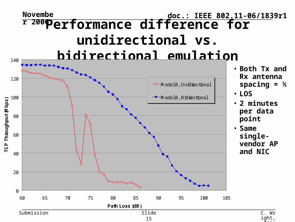
Performance difference for unidirectional vs. bidirectional emulation
• Both Tx and Rx antenna spacing = ½
• LOS• 2 minutes per
data point• Same single-
vendor AP and NIC
0
20
40
60
80
100
120
140
60 65 70 75 80 85 90 95 100 105
Path Loss (dB)
TC
P T
hro
ug
hp
ut
(Mb
ps)
Model B, Unidirectional
Model B, Bidirectional

November 2006
C. Wright, Azimuth Systems
Slide 16
doc.: IEEE 802.11-06/1839r1
Submission
The TGn models also apply to SISO
• The models were developed for the MIMO case
• But multipath for SISO systems is a special case of MIMO where the number of antennas on both nodes is one
• But also, many “SISO” systems are actually “SIMO”: one transmit antenna and two receive antennas– Switched diversity, or
– Maximal Ratio Combining (MRC)
• The TGn models naturally apply to these situations as well
• Existing commonly-used SISO models [2], [3] are truly SISO-only and are not capable of accurate diversity testing
November 2006
C. Wright, Azimuth Systems
Slide 17
doc.: IEEE 802.11-06/1839r1
Submission
Proposed changes to the TGT draft for implementing MIMO throughput tests
• Changes are mainly implemented as an augmentation to the conducted test environment (subclause 5.3)
• Several new figures are added to describe the MIMO setup
• Guidelines are described for proper use of these setups• Minimal changes to metrics clauses• TGn models specification?
– Asking IEEE-SA how to handle this
• This text is not yet complete, but submitted to give an idea of how this would be implemented in the draft

November 2006
C. Wright, Azimuth Systems
Slide 18
doc.: IEEE 802.11-06/1839r1
Submission
Impact on our current metrics (1/2)
• 6.3 – Throughput vs. attenuation in conducted environment– Directly applicable as an environment choice– Both non-multipath (Butler) and multipath applicable
• 6.4 – Transmit rate adaptation– Directly applicable as an environment choice– Test best carried out using non-multipath
• 6.5 – Antenna diversity– Methodology not really applicable for MIMO devices– Diversity performance “built in” to any MIMO test with channel emulator
• 6.6, 6.7, 6.18 – Throughput in OTA environments, coexistence of overlapping BSS– Not applicable to OTA environments
• 6.8 – Adjacent channel interference– Applicable using Butler matrix to connect devices– Multipath not applicable in this case
November 2006
C. Wright, Azimuth Systems
Slide 19
doc.: IEEE 802.11-06/1839r1
Submission
Impact on our current metrics (2/2)
• 6.9, 6.10 – (Fast) BSS transition time– Directly applicable – use Butler matrices in each AP path– Interesting and useful to measure performance with multipath vs. path loss
• 6.11 – Receiver sensitivity in conducted environment– Directly applicable using Butler matrix– Multipath not applicable in this case
• 6.12-6.16 – Intra-BSS, ESS throughput, multicast forwarding rate, association rate, etc.
– Directly applicable using Butler matrix to connect wireless devices– Interesting and useful to measure performance with multipath vs. path loss
• 6.17 – Power consumption– Directly applicable using Butler matrix to connect wireless devices
• 6.19-6.22 – Packet loss, latency, jitter, video performance– Directly applicable using Butler matrix to connect wireless devices– Interesting and useful to measure performance with multipath vs. path loss

November 2006
C. Wright, Azimuth Systems
Slide 20
doc.: IEEE 802.11-06/1839r1
Submission
Motion
• Motion to accept proposal in document 11-06/xxxxr0 into the P802.11.2 draft
• Move/second:
• Y/N/A:

November 2006
C. Wright, Azimuth Systems
Slide 21
doc.: IEEE 802.11-06/1839r1
Submission
References
• [1] IEEE 802.11-03/940r4, “TGn Channel Models”, V. Erceg, et al
• [2] IEEE 802.11-06/1501r0, “Multipath testing in a conducted environment”, C. Wright
• [3] IEEE 802.11-97/96, “Tentative Criteria for Comparison of Modulation Methods”, N. Chayat
• [4] 3ERI085B, “Channel models for HIPERLAN/2 in different indoor scenarios”, J. Medbo, et al