Embed Size (px)
DESCRIPTION
bjb
Citation preview
BRILLIANT PUBLIC SCHOOL, SITAMARHI
(Affiliated up to +2 level to C.B.S.E., New Delhi)
Class-XII
IIT-JEE Advanced Physics
Study Package
Session: 2014-15
Office: Rajopatti, Dumra Road, Sitamarhi (Bihar), Pin-843301
Ph.06226-252314 , Mobile:9431636758, 9931610902 Website: www.brilliantpublicschool.com; E-mail: [email protected]

STUDY PACKAGE
Target: IIT-JEE (Advanced)
SUBJECT: PHYSICS-XII Chapters:
1. Electrostatics
2. Capacitance
3. Current Electricity
4. Thermal and Chemical Effects of Electric Current
5. Magnetic Effects of Electric Current
6. Electromagnetic Induction and Alternating Current
7. Optics
8. Optical Instruments 9. Wave Optics 10. Modern Physics 11. Semiconductors Electronics
STUDY PACKAGE
Target: IIT-JEE (Advanced)
SUBJECT: PHYSICS
TOPIC: XII P1. Electrostatics
Index:
1. Key Concepts
2. Exercise I
3. Exercise II
4. Exercise III
5. Exercise IV
6. Answer Key
7. 34 Yrs. Que. from IIT-JEE
8. 10 Yrs. Que. from AIEEE
1
Page
2 o
f 16 E
LE
CT
RO
ST
AT
ICS
KEY CONCEPTS1. ELECTRIC CHARGE
Charge of a material body is that possesion (acquired or natural) due to which it strongly interacts
with other material body. It can be postive or negative. S.I. unit is coulomb. Charge is quantized,
conserved, and additive.
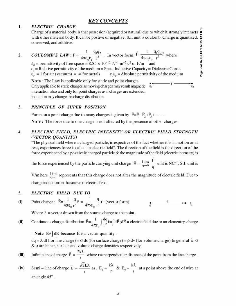
2. COULOMB’S LAW : F = 221
r0 r
4
1
επε. In vector form r
r
4
1F
321
r0
επε= where
ε0 = permittivity of free space = 8.85 × 10⁻¹² N−1 m−2 c2 or F/m and
εr = Relative permittivity of the medium = Spec. Inductive Capacity = Dielectric Const.
εr
= 1 for air (vacuum) = ∞ for metals ε0ε
r = Absolute permittivity of the medium
NOTE : The Law is applicable only for static and point charges.
Only applicable to static charges as moving charges may result magnetic
interaction also and only for point charges as if charges are extended,
induction may change the charge distribution.
3. PRINCIPLE OF SUPER POSITION
Force on a point charge due to many charges is given by ..........FFFF321+++=
NOTE : The force due to one charge is not affected by the presence of other charges.
4. ELECTRIC FIELD, ELECTRIC INTENSITY OR ELECTRIC FIELD STRENGTH
(VECTOR QUANTITY)
“The physical field where a charged particle, irrespective of the fact whether it is in motion or at
rest, experiences force is called an electric field”. The direction of the field is the direction of the
force experienced by a positively charged particle & the magnitude of the field (electric intensity) is
the force experienced by the particle carrying unit charge E
= 0q
Lim→
q
F
unit is NC–1; S.I. unit is
V/m here 0q
Lim→ represents that this charge does not alter the magnitude of electric field. Due to
charge induction on the source of electric field.
5. ELECTRIC FIELD DUE TO
(i) Point charge : rr
q
4
1E
20
πε=
= rr
q
4
13
0
∈π (vector form)
Where r = vector drawn from the source charge to the point .
(ii) Continuous charge distribution Ed;Edrr
dq
4
1E
20
∫∫ =πε
= = electric field due to an elementry charge
. Note ∫≠ dEE because E is a vector quantity .
dq = λ dl (for line charge) = σ ds (for surface charge) = ρ dv (for volume charge) In general λ, σ& ρ are linear, surface and volume charge densities respectively.
(iii) Infinite line of charge E =
r
k2 λ where r = perpendicular distance of the point from the line charge .
(iv) Semi ∞ line of charge E =
r
k2 λ as
, E
x =
r
kλ& E
y =
r
kλ at a point above the end of wire at
an angle 45º .
2

Page
3 o
f 16 E
LE
CT
RO
ST
AT
ICS
(v) Uniformly charged ring , Ecentre
= 0 , Eaxis
=2/322 )( Rx
xQk
+
(vi) Electric field is maximum when dE
dx= 0 for a point on the axis of the ring. Here we get x = R/√2.
(vii) Infinite non conducting sheet of charge n2
E0
εσ
=
where
n = unit normal vector to the plane of sheet, where σ is surface charge density
(viii) ∞ charged conductor sheet having surface charge density σ on both surfaces E = σ/ε0 .
(ix) Just outside a conducting surface charged with a surface charge density σ, electric field is always given as
E = σ/∈0.
(x) Uniformly charged solid sphere (Insulating material) Eout
= 2
0r4
Q
πε; r ≥ R ,
Behaves as a point charge situated at the centre for these points Ein
=0
30
3
r
R4
Qr
ερ
=πε
;
r ≤ R where ρ = volume charge density
(xi) Uniformly charged spherical shell (conducting or non-donducting) or uniformly charged solid
conducting sphere . Eout
= 2
0r4
Q
πε; r ≥ R
Behaves as a point charge situated at the centre for these points Ein
= 0 ; r < R
(xii) uniformly charged cylinder with a charge density ρ is -(radius of cylinder = R) for r < R
Em
=ρr
2 0∈ ; for r > R E =ρR
r
2
02 ∈(xiii) Uniformly charged cylinderical shell with surface charge density σ is
for r < R Em
= 0 ; for r > R E = ρr
r∈0
6. ELECTRIC LINES OF FORCE (ELF)
The line of force in an electric field is a hypothetical line, tangent to which at any point on it represents
the direction of electric field at the given point.
Properties of (ELF) :
(i) Electric lines of forces never intersects .
(ii) ELF originates from positive charge or ∞ and terminate on a negative charge of infinity .
(iii) Preference of termination is towards a negative charge .
(iv) If an ELF is originated, it must require termination either at a negetive charge or at ∞ .
(v) Quantity of ELF originated or terminated from a charge or on a charge is proportional to the
magnitude of charge.
7. ELECTROSTATIC EQUILIBRIUM
Position where net force (or net torque) on a charge(or electric dipole) = 0
(i) STABLE EQUILIBRIUM : If charge is displaced by a small distance the charge comes (or tries to
come back) to the equilibrium .
(ii) UNSTABLE EQUILIBRIUM : If charge is displaced by a small distance the charge does not return to
the equilibrium position.
3
Page
4 o
f 16 E
LE
CT
RO
ST
AT
ICS
8. ELECTRIC POTENTIAL (Scalar Quantity)
“Work done by external agent to bring a unit positive charge(without accelaration) from infinity to
a point in an electric field is called electric potential at that point” .
If W∞ r is the work done to bring a charge q (very small) from infinity to a point then potential at that
point is V = q
)W(extr∞
; S.I. unit is volt ( = 1 J/C)
9. POTENTIAL DIFFERENCE
VAB
= VA
− VB =
q
)W(extBA
VAB
= p.d. between point A & B .
WBA
= w.d. by external source to transfer a point charge q from B to A (Without acceleration).
10. ELECTRIC FIELD & ELECTRIC POINTENIAL
E = − grad V = − ∇ V read as gradient of V grad =
zk
yj
xi
∂∂
+∂∂
+∂∂
;
Used when EF varies in three dimensional coordinate system.
For finding potential difference between two points in electric field, we use –
VA – V
B =
→→− ∫ dt.E
B
A
if E is varying with distance
if E is constant & here d is the distance between points A and B.
11. POTENTIAL DUE TO
(i) a point charge V = r4
Q
0πε
(ii) many charges V = 30
3
20
2
10
1
r4
q
r4
q
r4
q
πε+
πε+
πε + ......
(iii) continuous charge distribution V = ∫πε r
dq
4
1
0
(iv) spherical shell (conducting or non conducting) or solid conducting sphere
Vout
=r4
Q
0πε; (r ≥ R) , VV
in =
R4
Q
0πε; (r ≤ R)
(v) non conducting uniformly charged solid sphere :
Vout
=r4
Q
0πε; (r ≥ R) , V
in =
R4
)rR3(Q
2
1
0
22
πε−
; (r ≤ R)
12. EQUIPOTENTIAL SURFACE AND EQUIPOTENTIAL REGION
In an electricfield the locus of points of equal potential is called an equipotential surface. An
equipotential surface and the electric field meet at right angles.
The region where E = 0, Potential of the whole region must remain constant as no work is done in
displacement of charge in it. It is called as equipotential region like conducting bodies.
4
Page
5 o
f 16 E
LE
CT
RO
ST
AT
ICS
13. MUTUAL POTENTIAL ENERGY OR INTERACTION ENERGY
“The work to be done to integrate the charge system .”
For 2 particle system Umutual
=r4
0
21
πε
For 3 particle system Umutual
=310
13
230
32
120
21
r4
r4
r4
πε+
πε+
πε
For n particles there will be n n( )−1
2terms . Total energy of a system = U
self + U
mutual
14. P.E. of charge q in potential field U = qV. Interaction energy of a system of two charges
U = q1V
2 = q
2V
1.
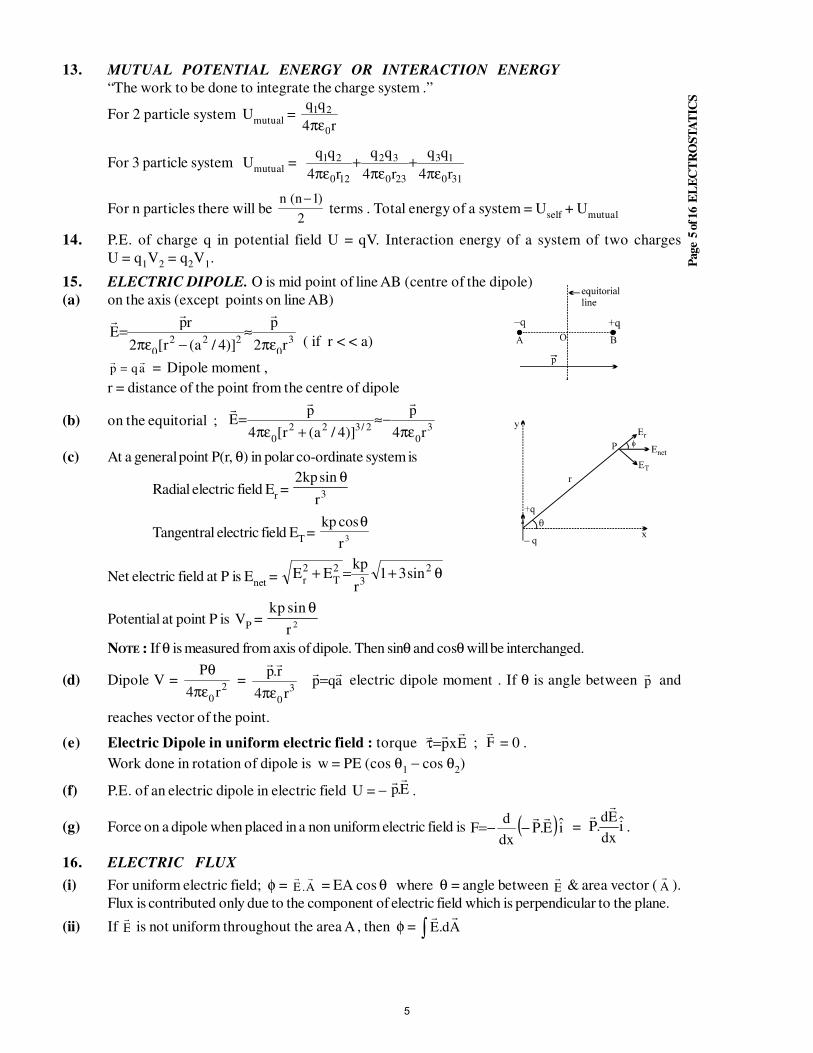
15. ELECTRIC DIPOLE. O is mid point of line AB (centre of the dipole)
(a) on the axis (except points on line AB)
3
0
222
0r2
p
)]4/a(r[2
rpE
πε≈
−πε=
( if r < < a)
p qa= = Dipole moment ,
r = distance of the point from the centre of dipole
(b) on the equitorial ; 3
02/322
0r4
p
)]4/a(r[4
pE
πε−≈
+πε=
(c) At a general point P(r, θ) in polar co-ordinate system is
Radial electric field Er = 3r
sinkp2 θ
Tangentral electric field ET =
kp
r
cosθ3
Net electric field at P is Enet
= θ+=+ 2
3
2T
2r
sin31r
kpEE
Potential at point P is VP =
kp
r
sin θ2
NOTE : If θ is measured from axis of dipole. Then sinθ and cosθ will be interchanged.
(d) Dipole V = 2
0r4
P
επ
θ =
30r4
r.p
επ
aqp
= electric dipole moment . If θ is angle between p and
reaches vector of the point.
(e) Electric Dipole in uniform electric field : torque Exp
=τ ; F
= 0 .
Work done in rotation of dipole is w = PE (cos θ1 − cos θ
2)
(f) P.E. of an electric dipole in electric field U = − E.p
.
(g) Force on a dipole when placed in a non uniform electric field is ( ) iE.Pdx
dF
−−= = i
dx
Ed.P
.
16. ELECTRIC FLUX
(i) For uniform electric field; φ = E A. = EA cos θ where θ = angle between
E & area vector (
A ).
Flux is contributed only due to the component of electric field which is perpendicular to the plane.
(ii) If E is not uniform throughout the area A , then φ = ∫ Ad.E
5
Page
6 o
f 16 E
LE
CT
RO
ST
AT
ICS
17. GAUSS’S LAW (Applicable only to closed surface) “ Net flux emerging out of a closed surface is
0
q
ε.” φ = ∫ AdE
=
0
q
ε q = net charge enclosed by the closed surface .
φ does not depend on the (i) shape and size of the closed surface
(ii) The charges located outside the closed surface.
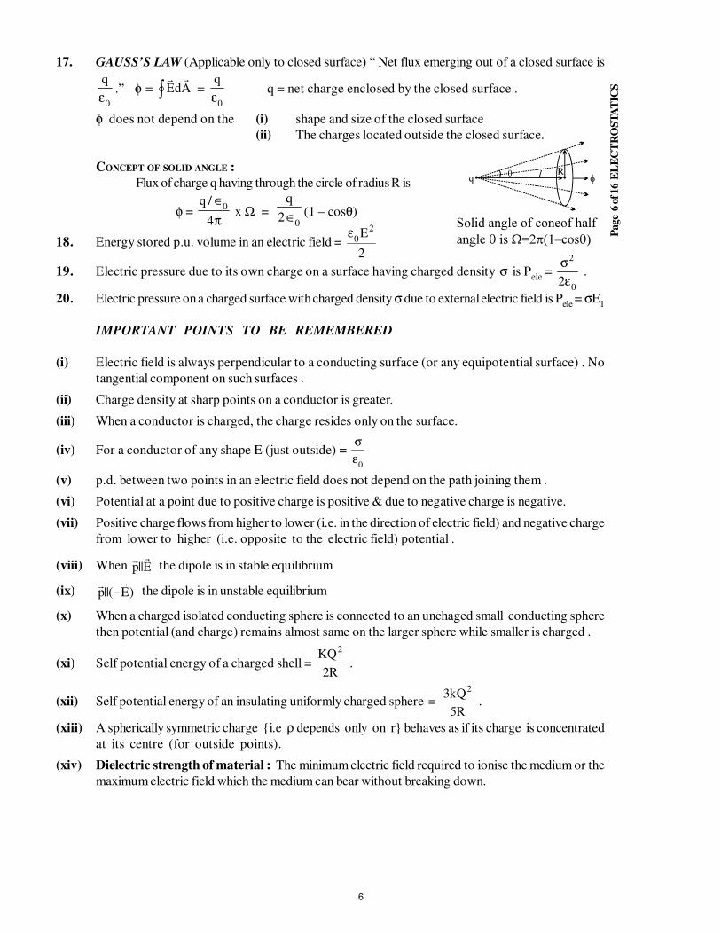
CONCEPT OF SOLID ANGLE :
Flux of charge q having through the circle of radius R is
φ =π
∈
4
/q0
x Ω =0
2
q
∈ (1 – cosθ)
18. Energy stored p.u. volume in an electric field =2
E20
ε
19. Electric pressure due to its own charge on a surface having charged density σ
is P
ele =
0
2
2εσ
.
20. Electric pressure on a charged surface with charged density σ due to external electric field is Pele
= σE1
IMPORTANT POINTS TO BE REMEMBERED
(i) Electric field is always perpendicular to a conducting surface (or any equipotential surface) . No
tangential component on such surfaces .
(ii) Charge density at sharp points on a conductor is greater.
(iii) When a conductor is charged, the charge resides only on the surface.
(iv) For a conductor of any shape E (just outside) = 0
εσ
(v) p.d. between two points in an electric field does not depend on the path joining them .
(vi) Potential at a point due to positive charge is positive & due to negative charge is negative.
(vii) Positive charge flows from higher to lower (i.e. in the direction of electric field) and negative charge
from lower to higher (i.e. opposite to the electric field) potential .
(viii) When E||p
the dipole is in stable equilibrium
(ix) )E(||p
− the dipole is in unstable equilibrium
(x) When a charged isolated conducting sphere is connected to an unchaged small conducting sphere
then potential (and charge) remains almost same on the larger sphere while smaller is charged .
(xi) Self potential energy of a charged shell = R2
KQ2
.
(xii) Self potential energy of an insulating uniformly charged sphere =
R5
Qk3 2
.
(xiii) A spherically symmetric charge i.e ρ depends only on r behaves as if its charge is concentrated
at its centre (for outside points).
(xiv) Dielectric strength of material : The minimum electric field required to ionise the medium or the
maximum electric field which the medium can bear without breaking down.
6
Page
7 o
f 16 E
LE
CT
RO
ST
AT
ICS
EXERCISE # I
Q.1 A negative point charge 2q and a positive charge q are fixed at a distance l apart. Where should a
positive test charge Q be placed on the line connecting the charge for it to be in equilibrium? What is the
nature of the equilibrium with respect to longitudinal motions?
Q.2 Two particles A and B each carrying a charge Q are held fixed with a separation d between then A
particle C having mass m ans charge q is kept at the midpoint of line AB. If it is displaced through a small
distance x (x << d) perpendicular to AB,
(a) then find the time period of the oscillations of C.
(b) If in the above question C is displaced along AB, find the time period of the oscillations of C.
Q.3 Draw E – r graph for 0 < r < b, if two point charges a & b are located r distance apart,
when
(i) both are + ve (ii) both are – ve
(iii) a is + ve and b is – ve (iv) a is – ve and b is + ve
Q.4 A c h a r g e +A c h a r g e +A c h a r g e +A c h a r g e + 10−9 C is located at the origin in free space & another charge Q at (2, 0, 0). If the
X−component of the electric field at (3, 1, 1) is zero, calculate the value of Q. Is the Y−component zero
at (3, 1, 1)?
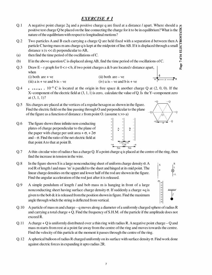
Q.5 Six charges are placed at the vertices of a regular hexagon as shown in the figure.
Find the electric field on the line passing through O and perpendicular to the plane
of the figure as a function of distance x from point O. (assume x >> a)
Q.6 The figure shows three infinite non-conducting
plates of charge perpendicular to the plane of
the paper with charge per unit area + σ, + 2σand – σ. Find the ratio of the net electric field at
that point A to that at point B.
Q.7 A thin circular wire of radius r has a charge Q. If a point charge q is placed at the centre of the ring, then
find the increase in tension in the wire.
Q.8 In the figure shown S is a large nonconducting sheet of uniform charge density σ. A
rod R of length l and mass ‘m’ is parallel to the sheet and hinged at its mid point. The
linear charge densities on the upper and lower half of the rod are shown in the figure.
Find the angular acceleration of the rod just after it is released.
Q.9 A simple pendulum of length l and bob mass m is hanging in front of a large
nonconducting sheet having surface charge density σ. If suddenly a charge +q is
given to the bob & it is released from the position shown in figure. Find the maximum
angle through which the string is deflected from vertical.
Q.10 A particle of mass m and charge – q moves along a diameter of a uniformly charged sphere of radius R
and carrying a total charge + Q. Find the frequency of S.H.M. of the particle if the amplitude does not
exceed R.
Q.11 A charge + Q is uniformly distributed over a thin ring with radius R. A negative point charge – Q and
mass m starts from rest at a point far away from the centre of the ring and moves towards the centre.
Find the velocity of this particle at the moment it passes through the centre of the ring.
Q.12 A spherical balloon of radius R charged uniformly on its surface with surface density σ. Find work done
against electric forces in expanding it upto radius 2R.
7
Page
8 o
f 16 E
LE
CT
RO
ST
AT
ICS
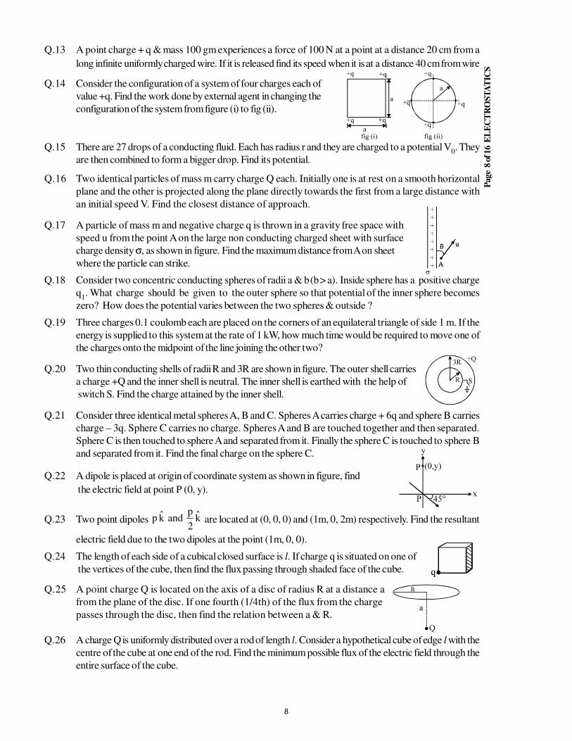
Q.13 A point charge + q & mass 100 gm experiences a force of 100 N at a point at a distance 20 cm from a
long infinite uniformly charged wire. If it is released find its speed when it is at a distance 40 cm from wire
Q.14 Consider the configuration of a system of four charges each of
value +q. Find the work done by external agent in changing the
configuration of the system from figure (i) to fig (ii).
Q.15 There are 27 drops of a conducting fluid. Each has radius r and they are charged to a potential V0. They
are then combined to form a bigger drop. Find its potential.
Q.16 Two identical particles of mass m carry charge Q each. Initially one is at rest on a smooth horizontal
plane and the other is projected along the plane directly towards the first from a large distance with
an initial speed V. Find the closest distance of approach.
Q.17 A particle of mass m and negative charge q is thrown in a gravity free space with
speed u from the point A on the large non conducting charged sheet with surface
charge density σ, as shown in figure. Find the maximum distance from A on sheet
where the particle can strike.
Q.18 Consider two concentric conducting spheres of radii a & b (b > a). Inside sphere has a positive charge
q1. What charge should be given to the outer sphere so that potential of the inner sphere becomes
zero? How does the potential varies between the two spheres & outside ?
Q.19 Three charges 0.1 coulomb each are placed on the corners of an equilateral triangle of side 1 m. If the
energy is supplied to this system at the rate of 1 kW, how much time would be required to move one of
the charges onto the midpoint of the line joining the other two?
Q.20 Two thin conducting shells of radii R and 3R are shown in figure. The outer shell carries
a charge +Q and the inner shell is neutral. The inner shell is earthed with the help of
switch S. Find the charge attained by the inner shell.
Q.21 Consider three identical metal spheres A, B and C. Spheres A carries charge + 6q and sphere B carries
charge – 3q. Sphere C carries no charge. Spheres A and B are touched together and then separated.
Sphere C is then touched to sphere A and separated from it. Finally the sphere C is touched to sphere B
and separated from it. Find the final charge on the sphere C.
Q.22 A dipole is placed at origin of coordinate system as shown in figure, find
the electric field at point P (0, y).
Q.23 Two point dipoles k2
pandkp are located at (0, 0, 0) and (1m, 0, 2m) respectively. Find the resultant
electric field due to the two dipoles at the point (1m, 0, 0).
Q.24 The length of each side of a cubical closed surface is l. If charge q is situated on one of
the vertices of the cube, then find the flux passing through shaded face of the cube.
Q.25 A point charge Q is located on the axis of a disc of radius R at a distance a
from the plane of the disc. If one fourth (1/4th) of the flux from the charge
passes through the disc, then find the relation between a & R.
Q.26 A charge Q is uniformly distributed over a rod of length l. Consider a hypothetical cube of edge l with the
centre of the cube at one end of the rod. Find the minimum possible flux of the electric field through the
entire surface of the cube.
8
Page
9 o
f 16 E
LE
CT
RO
ST
AT
ICS
EXERCISE # II
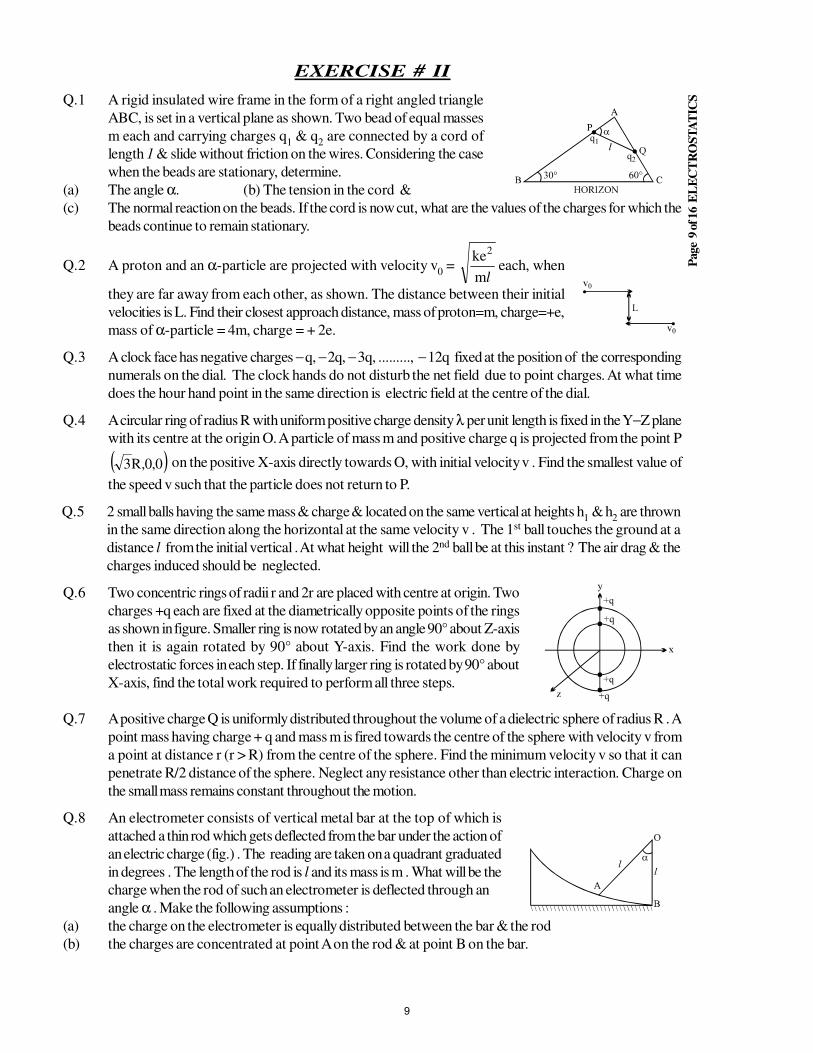
Q.1 A rigid insulated wire frame in the form of a right angled triangle
ABC, is set in a vertical plane as shown. Two bead of equal masses
m each and carrying charges q1 & q
2 are connected by a cord of
length 1 & slide without friction on the wires. Considering the case
when the beads are stationary, determine.
(a) The angle α. (b) The tension in the cord &
(c) The normal reaction on the beads. If the cord is now cut, what are the values of the charges for which the
beads continue to remain stationary.
Q.2 A proton and an α-particle are projected with velocity v0 =
lm
ke2
each, when
they are far away from each other, as shown. The distance between their initial
velocities is L. Find their closest approach distance, mass of proton=m, charge=+e,
mass of α-particle = 4m, charge = + 2e.
Q.3 A clock face has negative charges − q, − 2q, − 3q, ........., − 12q fixed at the position of the corresponding
numerals on the dial. The clock hands do not disturb the net field due to point charges. At what time
does the hour hand point in the same direction is electric field at the centre of the dial.
Q.4 A circular ring of radius R with uniform positive charge density λ per unit length is fixed in the Y−Z plane
with its centre at the origin O. A particle of mass m and positive charge q is projected from the point P
( )0,0,R3 on the positive X-axis directly towards O, with initial velocity v . Find the smallest value of
the speed v such that the particle does not return to P.
Q.5 2 small balls having the same mass & charge & located on the same vertical at heights h1 & h
2 are thrown
in the same direction along the horizontal at the same velocity v . The 1st ball touches the ground at a
distance l from the initial vertical . At what height will the 2nd ball be at this instant ? The air drag & the
charges induced should be neglected.
Q.6 Two concentric rings of radii r and 2r are placed with centre at origin. Two
charges +q each are fixed at the diametrically opposite points of the rings
as shown in figure. Smaller ring is now rotated by an angle 90° about Z-axis
then it is again rotated by 90° about Y-axis. Find the work done by
electrostatic forces in each step. If finally larger ring is rotated by 90° about
X-axis, find the total work required to perform all three steps.
Q.7 A positive charge Q is uniformly distributed throughout the volume of a dielectric sphere of radius R . A
point mass having charge + q and mass m is fired towards the centre of the sphere with velocity v from
a point at distance r (r > R) from the centre of the sphere. Find the minimum velocity v so that it can
penetrate R/2 distance of the sphere. Neglect any resistance other than electric interaction. Charge on
the small mass remains constant throughout the motion.
Q.8 An electrometer consists of vertical metal bar at the top of which is
attached a thin rod which gets deflected from the bar under the action of
an electric charge (fig.) . The reading are taken on a quadrant graduated
in degrees . The length of the rod is l and its mass is m . What will be the
charge when the rod of such an electrometer is deflected through an
angle α . Make the following assumptions :
(a) the charge on the electrometer is equally distributed between the bar & the rod
(b) the charges are concentrated at point A on the rod & at point B on the bar.
9
Page
10 o
f 16 E
LE
CT
RO
ST
AT
ICS
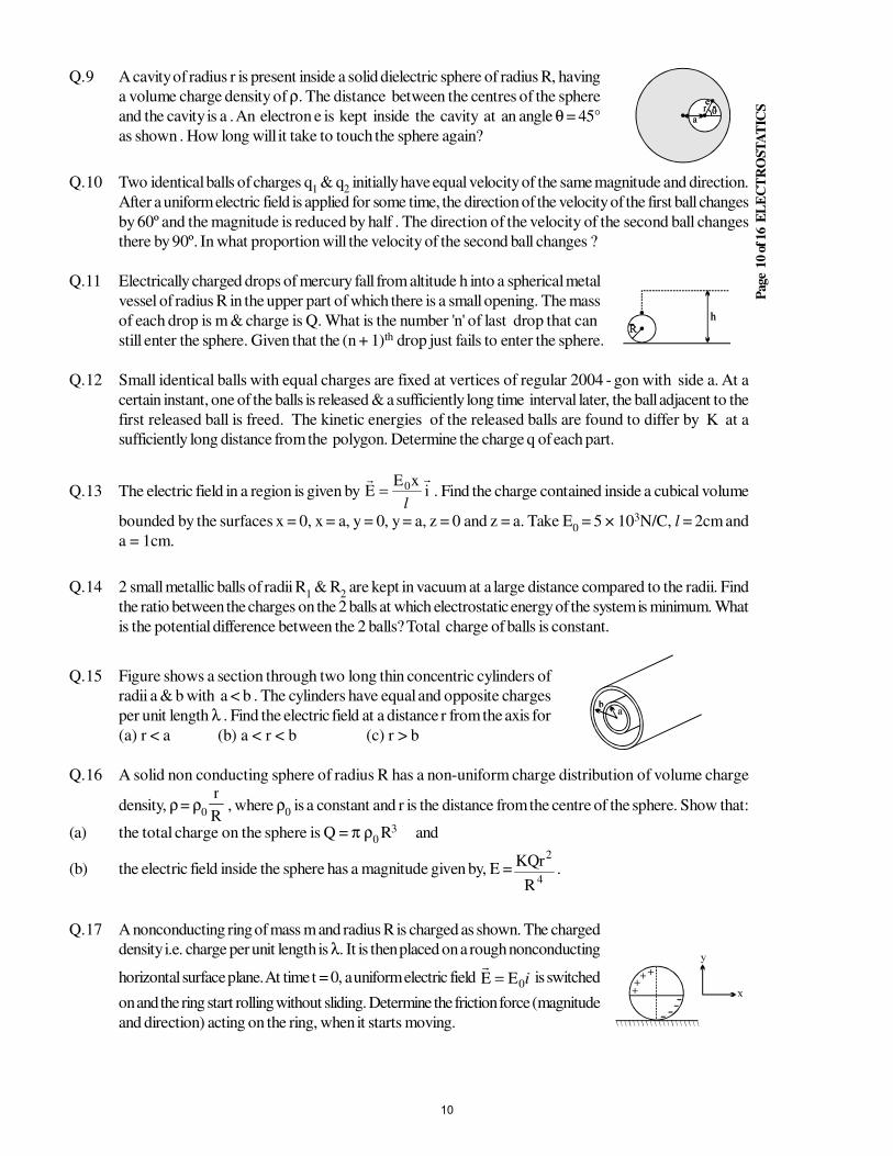
Q.9 A cavity of radius r is present inside a solid dielectric sphere of radius R, having
a volume charge density of ρ. The distance between the centres of the sphere
and the cavity is a . An electron e is kept inside the cavity at an angle θ = 45°
as shown . How long will it take to touch the sphere again?
Q.10 Two identical balls of charges q1 & q
2 initially have equal velocity of the same magnitude and direction.
After a uniform electric field is applied for some time, the direction of the velocity of the first ball changes
by 60º and the magnitude is reduced by half . The direction of the velocity of the second ball changes
there by 90º. In what proportion will the velocity of the second ball changes ?
Q.11 Electrically charged drops of mercury fall from altitude h into a spherical metal
vessel of radius R in the upper part of which there is a small opening. The mass
of each drop is m & charge is Q. What is the number 'n' of last drop that can
still enter the sphere. Given that the (n + 1)th drop just fails to enter the sphere.
Q.12 Small identical balls with equal charges are fixed at vertices of regular 2004 - gon with side a. At a
certain instant, one of the balls is released & a sufficiently long time interval later, the ball adjacent to the
first released ball is freed. The kinetic energies of the released balls are found to differ by K at a
sufficiently long distance from the polygon. Determine the charge q of each part.
Q.13 The electric field in a region is given by ixE
E 0
l= . Find the charge contained inside a cubical volume
bounded by the surfaces x = 0, x = a, y = 0, y = a, z = 0 and z = a. Take E0 = 5 × 10³N/C, l = 2cm and
a = 1cm.
Q.14 2 small metallic balls of radii R1 & R
2 are kept in vacuum at a large distance compared to the radii. Find
the ratio between the charges on the 2 balls at which electrostatic energy of the system is minimum. What
is the potential difference between the 2 balls? Total charge of balls is constant.
Q.15 Figure shows a section through two long thin concentric cylinders of
radii a & b with a < b . The cylinders have equal and opposite charges
per unit length λ . Find the electric field at a distance r from the axis for
(a) r < a (b) a < r < b (c) r > b
Q.16 A solid non conducting sphere of radius R has a non-uniform charge distribution of volume charge
density, ρ = ρ
0 R
r, where ρ
0 is a constant and r is the distance from the centre of the sphere. Show that:
(a) the total charge on the sphere is Q = π ρ0 R3 and
(b) the electric field inside the sphere has a magnitude given by, E =4
2
R
rQK.
Q.17 A nonconducting ring of mass m and radius R is charged as shown. The charged
density i.e. charge per unit length is λ. It is then placed on a rough nonconducting
horizontal surface plane. At time t = 0, a uniform electric field i0EE =
is switched
on and the ring start rolling without sliding. Determine the friction force (magnitude
and direction) acting on the ring, when it starts moving.
10
Page
11 o
f 16 E
LE
CT
RO
ST
AT
ICS
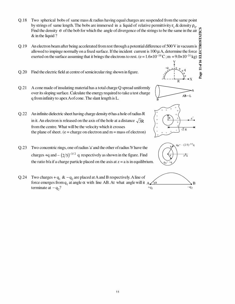
Q.18 Two spherical bobs of same mass & radius having equal charges are suspended from the same point
by strings of same length. The bobs are immersed in a liquid of relative permittivity εr & density ρ
0.
Find the density σ of the bob for which the angle of divergence of the strings to be the same in the air
& in the liquid ?
Q.19 An electron beam after being accelerated from rest through a potential difference of 500 V in vacuum is
allowed to impinge normally on a fixed surface. If the incident current is 100 µ A, determine the force
exerted on the surface assuming that it brings the electrons to rest. (e = 1.6×10⁻¹⁹ C ; m = 9.0×10⁻³¹ kg)
Q.20 Find the electric field at centre of semicircular ring shown in figure.
Q.21 A cone made of insulating material has a total charge Q spread uniformly
over its sloping surface. Calculate the energy required to take a test charge
q from infinity to apex A of cone. The slant length is L.
Q.22 An infinite dielectric sheet having charge density σ has a hole of radius R
in it. An electron is released on the axis of the hole at a distance R3
from the centre. What will be the velocity which it crosses
the plane of sheet. (e = charge on electron and m = mass of electron)
Q.23 Two concentric rings, one of radius 'a' and the other of radius 'b' have the
charges +q and – ( ) 2/352
− q respectively as shown in the figure. Find
the ratio b/a if a charge particle placed on the axis at z = a is in equilibrium.
Q.24 Two charges + q1 & −
q2 are placed at A and B respectively. A line of
force emerges from q1 at angle α with line AB. At what angle will it
terminate at − q2?
11
Page
12 o
f 16 E
LE
CT
RO
ST
AT
ICS
EXERCISE # III
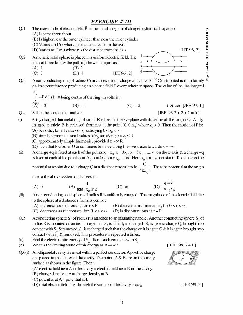
Q.1 The magnitude of electric field E in the annular region of charged cylindrical capacitor
(A) Is same throughout
(B) Is higher near the outer cylinder than near the inner cylinder
(C) Varies as (1/r) where r is the distance from the axis
(D) Varies as (1/r2) where r is the distance from the axis [IIT '96, 2]
Q.2 A metallic solid sphere is placed in a uniform electric field. The
lines of force follow the path (s) shown in figure as :
(A) 1 (B) 2
(C) 3 (D) 4 [IIT'96 , 2]
Q.3 A non-conducting ring of radius 0.5 m carries a total charge of 1.11 × 10⁻¹⁰ C distributed non-uniformly
on its circumference producing an electric field E every where in space. The value of the line integral
d.E
0
−∫=
∞=
(l = 0 being centre of the ring) in volts is :
(A) + 2 (B) − 1 (C) − 2 (D) zero[JEE '97, 1 ]
Q.4 Select the correct alternative : [JEE '98 2 + 2 + 2 = 6 ]
(i) A + ly charged thin metal ring of radius R is fixed in the xy−plane with its centre at the origin O . A – ly
charged particle P is released from rest at the point (0, 0, z0) where z
0 > 0 . Then the motion of P is:
(A) periodic, for all values of z0 satisfying 0 < z
0 < ∞
(B) simple harmonic, for all values of z0 satisfying 0 < z
0 ≤ R
(C) approximately simple harmonic, provided z0 << R
(D) such that P crosses O & continues to move along the −ve z-axis towards x = −∞(ii) A charge +q is fixed at each of the points x = x
0, x = 3x
0, x = 5x
0, ...... ∞ on the x-axis & a charge −q
is fixed at each of the points x = 2x0, x = 4x
0, x = 6x
0, .... ∞ . Here x
0 is a +ve constant . Take the electric
potential at a point due to a charge Q at a distance r from it to be r4
Q
0∈π
. Then the potential at the origin
due to the above system of charges is :
(A) 0 (B) 2nx8
q
00∈π (C) ∞ (D)
00x4
2nq
∈π
(iii) A non-conducting solid sphere of radius R is uniformly charged . The magnitude of the electric field due
to the sphere at a distance r from its centre :
(A) increases as r increases, for r < R (B) decreases as r increases, for 0 < r < ∞(C) decreases as r increases, for R < r < ∞ (D) is discontinuous at r = R .
Q.5 A conducting sphere S1 of radius r is attached to an insulating handle . Another conducting sphere S
2 of
radius R is mounted on an insulating stand . S2 is initially uncharged . S
1 is given a charge Q, brought into
contact with S2 & removed, S
1 is recharged such that the charge on it is again Q & it is again brought into
contact with S2 & removed. This procedure is repeated n times.
(a) Find the electrostatic energy of S2 after n such contacts with S
1.
(b) What is the limiting value of this energy as n → ∞? [ JEE '98, 7 + 1 ]
Q.6(i) An ellipsoidal cavity is carved within a perfect conductor. A positive charge
q is placed at the center of the cavity. The points A & B are on the cavity
surface as shown in the figure. Then :
(A) electric field near A in the cavity = electric field near B in the cavity
(B) charge density at A = charge density at B
(C) potential at A = potential at B
(D) total electric field flux through the surface of the cavity is q/ε0 . [ JEE '99, 3 ]
12
(ii) A non-conducting disc of radius a and uniform positive surface charge density σ is placed on the ground,
with its axis vertical . A particle of mass m & positive charge q is dropped, along the axis of the disc, from
a height H with zero initial velocity. The particle has m
q =
σ
ε g40 .
(a) Find the value of H if the particle just reaches the disc .
(b) Sketch the potential energy of the particle as a function of its height and find its equilibrium position.
[ JEE '99, 5 + 5 ]
Q.7(a) The dimension of ( )21 e
0 E2 (e
0 : permittivity of free space ; E : electric field) is :
(A) M L T −1 (B) M L2 T − 2 (C) M L T −2 (D) M L2 T − 1 (E) M L−1 T − 2
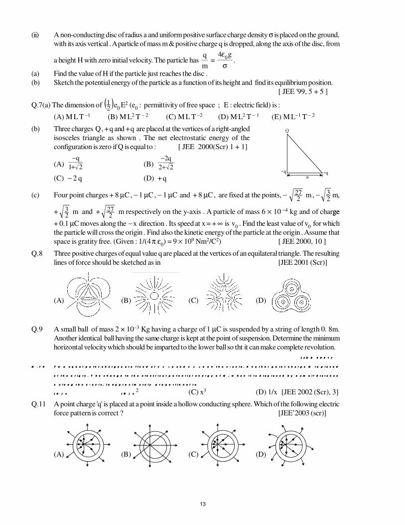
(b) Three charges Q , + q and + q are placed at the vertices of a right-angled
isosceles triangle as shown . The net electrostatic energy of the
configuration is zero if Q is equal to : [ JEE 2000(Scr) 1 + 1]
(A) 21
q
+−
(B) 22
q2
+−
(C) − 2 q (D) + q
(c) Four point charges + 8 µC , − 1 µC , − 1 µC and + 8 µC , are fixed at the points, −
227 m , −
23 m,
+23 m and +
227 m respectively on the y-axis . A particle of mass 6 × 10 −4 kg and of chargege
+ 0.1 µC moves along the − x direction . Its speed at x = + ∞ is v0 . Find the least value of v
0 for which
the particle will cross the origin . Find also the kinetic energy of the particle at the origin . Assume that
space is gratity free. (Given : 1/(4 π ε0) = 9 × 10⁹ Nm2/C2) [ JEE 2000, 10 ]
Q.8 Three positive charges of equal value q are placed at the vertices of an equilateral triangle. The resulting
lines of force should be sketched as in [JEE 2001 (Scr)]
(A) (B) (C) (D)
Q.9 A small ball of mass 2 × 10⁻³ Kg having a charge of 1 µC is suspended by a string of length 0. 8m.
Another identical ball having the same charge is kept at the point of suspension. Determine the minimum
horizontal velocity which should be imparted to the lower ball so tht it can make complete revolution.
[ J E E 2 0 0 1 ][ J E E 2 0 0 1 ][ J E E 2 0 0 1 ][ J E E 2 0 0 1 ]
Q . 1 0Q . 1 0Q . 1 0Q . 1 0 T w o e q u a l p o i n t c h a r g e s a r e f i x e d a t x = – a a n d x = + a o n t h e x - a x i s . A n o t h e r p o i n t c h a r g e Q i s p l a c e dT w o e q u a l p o i n t c h a r g e s a r e f i x e d a t x = – a a n d x = + a o n t h e x - a x i s . A n o t h e r p o i n t c h a r g e Q i s p l a c e dT w o e q u a l p o i n t c h a r g e s a r e f i x e d a t x = – a a n d x = + a o n t h e x - a x i s . A n o t h e r p o i n t c h a r g e Q i s p l a c e dT w o e q u a l p o i n t c h a r g e s a r e f i x e d a t x = – a a n d x = + a o n t h e x - a x i s . A n o t h e r p o i n t c h a r g e Q i s p l a c e d
a t t h e o r i g i n . T h e c h a n g e i n t h e e l e c t r i c a l p o t e n t i a l e n e r g y o f Q , w h e n i t i s d i s p l a c e d b y a s m a l l d i s t a n c ea t t h e o r i g i n . T h e c h a n g e i n t h e e l e c t r i c a l p o t e n t i a l e n e r g y o f Q , w h e n i t i s d i s p l a c e d b y a s m a l l d i s t a n c ea t t h e o r i g i n . T h e c h a n g e i n t h e e l e c t r i c a l p o t e n t i a l e n e r g y o f Q , w h e n i t i s d i s p l a c e d b y a s m a l l d i s t a n c ea t t h e o r i g i n . T h e c h a n g e i n t h e e l e c t r i c a l p o t e n t i a l e n e r g y o f Q , w h e n i t i s d i s p l a c e d b y a s m a l l d i s t a n c e
x a l o n g t h e x - a x i s , i s a p p r o x i m a t e l y p r o p o r t i o n a l t ox a l o n g t h e x - a x i s , i s a p p r o x i m a t e l y p r o p o r t i o n a l t ox a l o n g t h e x - a x i s , i s a p p r o x i m a t e l y p r o p o r t i o n a l t ox a l o n g t h e x - a x i s , i s a p p r o x i m a t e l y p r o p o r t i o n a l t o
( A ) x( A ) x( A ) x( A ) x ( B ) x( B ) x( B ) x( B ) x2 (C) x3 (D) 1/x [JEE 2002 (Scr), 3]
Q.11 A point charge 'q' is placed at a point inside a hollow conducting sphere. Which of the following electric
force pattern is correct ? [JEE’2003 (scr)]
(A) (B) (C) (D)
13
Page
14 o
f 16 E
LE
CT
RO
ST
AT
ICS
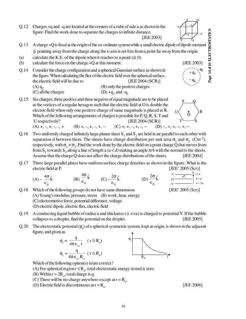
Q.12 Charges +q and –q are located at the corners of a cube of side a as shown in the
figure. Find the work done to separate the charges to infinite distance.
[JEE 2003]
Q.13 A charge +Q is fixed at the origin of the co-ordinate system while a small electric dipole of dipole-moment
p
pointing away from the charge along the x-axis is set free from a point far away from the origin.
(a) calculate the K.E. of the dipole when it reaches to a point (d, 0)
(b) calculate the force on the charge +Q at this moment. [JEE 2003]
Q.14 Consider the charge configuration and a spherical Gaussian surface as shown in
the figure. When calculating the flux of the electric field over the spherical surface,
the electric field will be due to [JEE 2004 (SCR)]
(A) q2
(B) only the positive charges
(C) all the charges (D) +q1 and -q
1
Q.15 Six charges, three positive and three negative of equal magnitude are to be placed
at the vertices of a regular hexagon such that the electric field at O is double the
electric field when only one positive charge of same magnitude is placed at R.
Which of the following arrangements of charges is possible for P, Q, R, S, T and
U respectively? [JEE 2004 (SCR)]
(A) +, -, +, -, -, + (B) +, -, +, -, +, − (C) +, +, -, +, -, − (D) −, +, +, −, +, −
Q.16 Two uniformly charged infinitely large planar sheet S1 and S
2 are held in air parallel to each other with
separation d between them. The sheets have charge distribution per unit area σ1 and σ
2 (Cm–2),
respectively, with σ1 > σ
2. Find the work done by the electric field on a point charge Q that moves from
from S1 towards S
2 along a line of length a (a < d) making an angle π/4 with the normal to the sheets.
Assume that the charge Q does not affect the charge distributions of the sheets. [JEE 2004]
Q.17 Three large parallel plates have uniform surface charge densities as shown in the figure. What is the
electric field at P. [JEE’ 2005 (Scr)]
(A) – k4
0∈
σ(B) k
4
0∈
σ(C) – k
2
0∈
σ(D) k
2
0∈
σ
Q.18 Which of the following groups do not have same dimensions [JEE’ 2005 (Scr)]
(A) Young’s modulus, pressure, stress (B) work, heat, energy
(C) electromotive force, potential difference, voltage
(D) electric dipole, electric flux, electric field
Q.19 A conducting liquid bubble of radius a and thickness t (t <<a) is charged to potential V. If the bubble
collapses to a droplet, find the potential on the droplet. [JEE 2005]
Q.20 The electrostatic potential (φr) of a spherical symmetric system, kept at origin, is shown in the adjacent
figure, and given as
φr =
r4
q
o∈π
( r ≥ Ro)
φr =
ooR4
q
∈π( r ≤ R
o)
Which of the following option(s) is/are correct?
(A) For spherical region r ≤ Ro, total electrostatic energy stored is zero.
(B) Within r = 2Ro, total charge is q.
(C) There will be no charge anywhere except at r = Ro.
(D) Electric field is discontinuous at r = Ro. [JEE 2006]
14
Page
15 o
f 16 E
LE
CT
RO
ST
AT
ICS
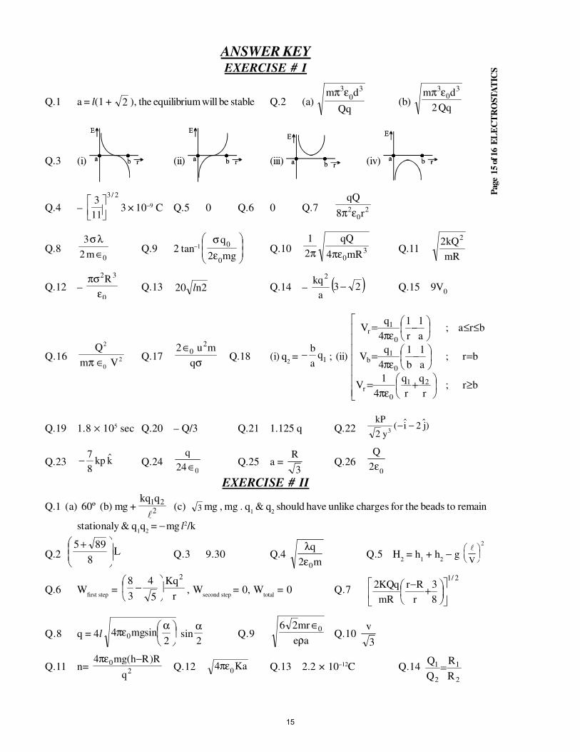
ANSWER KEYEXERCISE # I
Q.1 a = l(1 + 2 ), the equilibrium will be stable Q.2 (a) Qq
dm 30
3επ(b)
Qq2
dm 30
3επ
Q.3 (i) (ii) (iii) (iv)
Q.4 –
2/3
11
3
3 × 10⁻⁹ C Q.5 0 Q.6 0 Q.7 2
02 r8
επ
Q.80m2
3
∈
λσQ.9 2 tan–1
ε
σ
mg2
q
0
0Q.10 3
0mR4
2
1
πεπ Q.11mR
kQ2 2
Q.12 – 0
32R
επσ
Q.13 2n20 l Q.14 – ( )23a
kq2
− Q.15 9V0
Q.16Q
m V
2
0
2π ∈Q.17
σ∈
q
mu2 20
Q.18 (i) q2 = 1
qa
b− ; (ii)
≥
+επ
=
=
−επ
=
≤≤
−επ
=
br;r
q
r
q
4
1V
br;a
1
b
1
4
qV
bra;a
1
r
1
4
qV
21
0r
0
1b
0
1r
Q.19 1.8 × 10⁵ sec Q.20 – Q/3 Q.21 1.125 q Q.22kP
yi j
22
3( )− −
Q.23 kkp8
7− Q.24
024
q
∈ Q.25 a =R
3Q.26
02
Q
ε
EXERCISE # II
Q.1 (a) 60º (b) mg + 2
21qqk
(c) 3 mg , mg . q
1 & q
2 should have unlike charges for the beads to remain
stationaly & q1q
2 = − mg l2/k
Q.2 L8
895
+Q.3 9.30 Q.4
m2
q
0ελ
Q.5 H2 = h
1 + h
2 − g
V
2
Q.6 Wfirst step
=r
Kq
5
4
3
8 2
− , W
second step = 0, W
total = 0 Q.7
2/1
8
3
r
Rr
Rm
qQK2
+−
Q.8 q = 4l
αεπ
2sinmg4 0 sin
2
αQ.9
ae
mr26 0
ρ∈
Q.10 3
v
Q.11 n= 2
0
q
R)Rh(gm4 −επQ.12 Ka4
0επ Q.13 2.2 × 10⁻¹²C Q.14
2
1
2
1
R
R
Q
Q=
15
Page
16 o
f 16 E
LE
CT
RO
ST
AT
ICS
Q.15 0, r
K2 λ, 0 Q.17 iER 0λ Q.18 σ
ε ρ
ε=
−r
r
0
1Q.19 7.5 × 10⁻⁹ N
Q.20 – iR
kq42π
Q.21L2
0∈π Q.22 v =0m
eR
εσ
Q.23 2
Q.24 b = 2 sin -1 sinα2
1
2
q
q
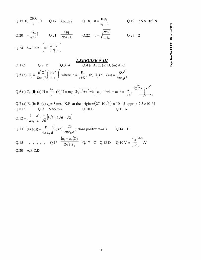
EXERCISE # IIIQ.1 C Q.2 D Q.3 A Q.4 (i) A, C, (ii) D, (iii) A, C
Q.5 (a) U2 =
2n
0
22
a1
a1
R8
Qa
−−
∈π where a =
Rr
R
+, (b) U
2 (n → ∞) =
20
2
r8
QR
∈π
Q.6 (i) C, (ii) (a) H = 3
a4, (b) U = mg
−+ hah2 22
equilibrium at h = a
3,
Q.7 (a) E, (b) B, (c) v0 = 3 m/s ; K.E. at the origin = )( 61027− × 10 −4 J approx.2.5 ×10 −4 J
Q.8 C Q.9 5.86 m/s Q.10 B Q.11 A
Q.12 – [ ]263336
4·
a
q
4
12
0
−−επ
Q.13 (a) 2
0 d
Q
4
PE.K
επ= , (b) 3
0 d2
QP
επ along positive x-axis Q.14 C
Q.15 -, +, +, -, +, - Q.16( )
0
21
22
Qa
ε
σ−σQ.17 C Q.18 D Q.19 V' =
3/1
t3
a
.V
Q.20 A,B,C,D
16

STUDY PACKAGE
Target: IIT-JEE (Advanced)
SUBJECT: PHYSICS
TOPIC: XII P2. Capacitance
Index:
1. Key Concepts
2. Exercise I
3. Exercise II
4. Exercise III
5. Exercise IV
6. Answer Key
7. 34 Yrs. Que. from IIT-JEE
8. 10 Yrs. Que. from AIEEE
1
Page
2 o
f 12 C
AP
AC
ITA
NC
E
KEY CONCEPTS
1. CAPACITANCE OF AN ISOLATED SPHERICAL CONDUCTOR :
C = 4π ∈0∈
r R in a medium C = 4π ∈
0 R in air
* This sphere is at infinite distance from all the conductors .
* The capacitance C = 4π ∈0 R exists between the surface of the sphere & earth .
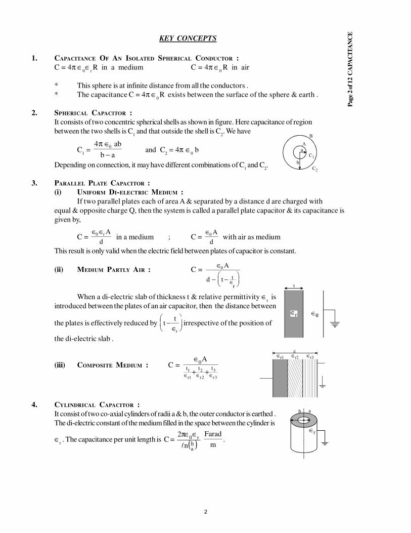
2. SPHERICAL CAPACITOR :
It consists of two concentric spherical shells as shown in figure. Here capacitance of region
between the two shells is C1 and that outside the shell is C
2. We have
C1 =
4 0π ∈
−
ab
b a and C
2 = 4π ∈
0 b
Depending on connection, it may have different combinations of C1 and C
2.
3. PARALLEL PLATE CAPACITOR :
(i) UNIFORM DI-ELECTRIC MEDIUM :
If two parallel plates each of area A & separated by a distance d are charged with
equal & opposite charge Q, then the system is called a parallel plate capacitor & its capacitance is
given by,
C = ∈ ∈0 r A
d in a medium ; C =
∈0 A
d with air as medium
This result is only valid when the electric field between plates of capacitor is constant.
(ii) MEDIUM PARTLY AIR : C = ∈
− −
∈
0 A
d t t
r
When a di-electric slab of thickness t & relative permittivity ∈r is
introduced between the plates of an air capacitor, then the distance between
the plates is effectively reduced by tt
r
−∈
irrespective of the position of
the di-electric slab .
(iii) COMPOSITE MEDIUM : C =
3r
3
2r
2
1r
1 ttt
A0
∈∈∈ ++
∈
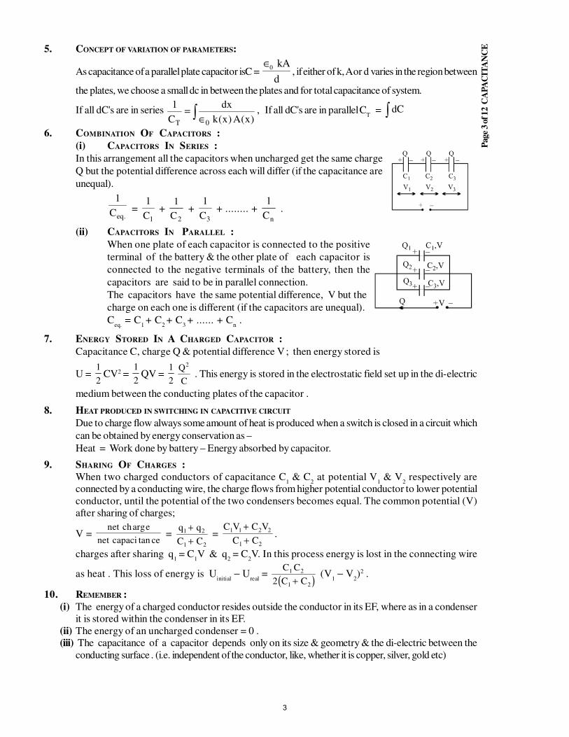
4. CYLINDRICAL CAPACITOR :
It consist of two co-axial cylinders of radii a & b, the outer conductor is earthed .
The di-electric constant of the medium filled in the space between the cylinder is
∈r . The capacitance per unit length is C = ( )
abn
2r0
∈∈π Farad
m.
2
Page
3 o
f 12 C
AP
AC
ITA
NC
E5. CONCEPT OF VARIATION OF PARAMETERS:
As capacitance of a parallel plate capacitor isC = ∈0 kA
d, if either of k, A or d varies in the region between
the plates, we choose a small dc in between the plates and for total capacitance of system.
If all dC's are in series ∫∈=
)x(A)x(k
dx
C
1
0T
, If all dC's are in parallelCT = dC∫
6. COMBINATION OF CAPACITORS :
(i) CAPACITORS IN SERIES :
In this arrangement all the capacitors when uncharged get the same charge
Q but the potential difference across each will differ (if the capacitance are
unequal).
.eqC
1 =
1C
1 +
2C
1 +
3C
1 + ........ +
nC
1 .
(ii) CAPACITORS IN PARALLEL :
When one plate of each capacitor is connected to the positive
terminal of the battery & the other plate of each capacitor is
connected to the negative terminals of the battery, then the
capacitors are said to be in parallel connection.
The capacitors have the same potential difference, V but the
charge on each one is different (if the capacitors are unequal).
Ceq.
= C1 + C
2 + C
3 + ...... + C
n .
7. ENERGY STORED IN A CHARGED CAPACITOR :
Capacitance C, charge Q & potential difference V ; then energy stored is
U = 1
2CV2 =
1
2QV =
1
2
Q
C
2
. This energy is stored in the electrostatic field set up in the di-electric
medium between the conducting plates of the capacitor .
8. HEAT PRODUCED IN SWITCHING IN CAPACITIVE CIRCUIT
Due to charge flow always some amount of heat is produced when a switch is closed in a circuit which
can be obtained by energy conservation as –
Heat = Work done by battery – Energy absorbed by capacitor.
9. SHARING OF CHARGES :
When two charged conductors of capacitance C1 & C
2 at potential V
1 & V
2 respectively are
connected by a conducting wire, the charge flows from higher potential conductor to lower potential
conductor, until the potential of the two condensers becomes equal. The common potential (V)
after sharing of charges;
V = net ch e
net capaci ce
arg
tan =
q q
C C
1 2
1 2
+
+ =
C V C V
C C
1 1 2 2
1 2
+
+.
charges after sharing q1 = C
1V & q
2 = C
2V. In this process energy is lost in the connecting wire
as heat . This loss of energy is Uinitial
− Ureal
= ( )C C
C C
1 2
1 22 +(V
1 − V
2)2 .
10. REMEMBER :
(i) The energy of a charged conductor resides outside the conductor in its EF, where as in a condenser
it is stored within the condenser in its EF.
(ii) The energy of an uncharged condenser = 0 .
(iii) The capacitance of a capacitor depends only on its size & geometry & the di-electric between the
conducting surface . (i.e. independent of the conductor, like, whether it is copper, silver, gold etc)
3
Page
4 o
f 12 C
AP
AC
ITA
NC
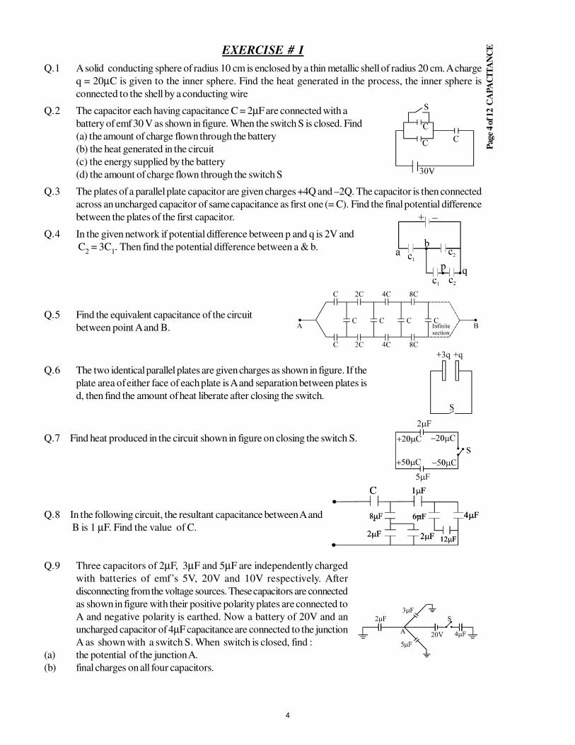
EEXERCISE # I
Q.1 A solid conducting sphere of radius 10 cm is enclosed by a thin metallic shell of radius 20 cm. A charge
q = 20µC is given to the inner sphere. Find the heat generated in the process, the inner sphere is
connected to the shell by a conducting wire
Q.2 The capacitor each having capacitance C = 2µF are connected with a
battery of emf 30 V as shown in figure. When the switch S is closed. Find
(a) the amount of charge flown through the battery
(b) the heat generated in the circuit
(c) the energy supplied by the battery
(d) the amount of charge flown through the switch S
Q.3 The plates of a parallel plate capacitor are given charges +4Q and –2Q. The capacitor is then connected
across an uncharged capacitor of same capacitance as first one (= C). Find the final potential difference
between the plates of the first capacitor.
Q.4 In the given network if potential difference between p and q is 2V and
C2 = 3C
1. Then find the potential difference between a & b.
Q.5 Find the equivalent capacitance of the circuit
between point A and B.
Q.6 The two identical parallel plates are given charges as shown in figure. If the
plate area of either face of each plate is A and separation between plates is
d, then find the amount of heat liberate after closing the switch.
Q.7 Find heat produced in the circuit shown in figure on closing the switch S.
Q.8 In the following circuit, the resultant capacitance between A and
B is 1 µF. Find the value of C.
Q.9 Three capacitors of 2µF, 3µF and 5µF are independently charged
with batteries of emf’s 5V, 20V and 10V respectively. After
disconnecting from the voltage sources. These capacitors are connected
as shown in figure with their positive polarity plates are connected to
A and negative polarity is earthed. Now a battery of 20V and an
uncharged capacitor of 4µF capacitance are connected to the junction
A as shown with a switch S. When switch is closed, find :
(a) the potential of the junction A.
(b) final charges on all four capacitors.
4
Page
5 o
f 12 C
AP
AC
ITA
NC
E
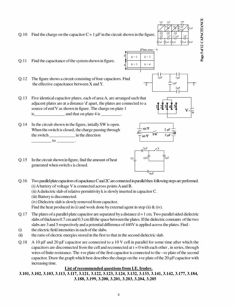
Q.10 Find the charge on the capacitor C = 1 µF in the circuit shown in the figure.
Q.11 Find the capacitance of the system shown in figure.
Q.12 The figure shows a circuit consisting of four capacitors. Find
the effective capacitance between X and Y.
Q.13 Five identical capacitor plates, each of area A, are arranged such that
adjacent plates are at a distance 'd' apart, the plates are connected to a
source of emf V as shown in figure. The charge on plate 1
is______________ and that on plate 4 is _________.
Q.14 In the circuit shown in the figure, intially SW is open.
When the switch is closed, the charge passing through
the switch ____________ in the direction
_________ to ________ .
Q.15 In the circuit shown in figure, find the amount of heat
generated when switch s is closed.
Q.16 Two parallel plate capacitors of capacitance C and 2C are connected in parallel then following steps are performed.
(i) A battery of voltage V is connected across points A and B.
(ii) A dielectric slab of relative permittivity k is slowly inserted in capacitor C.
(iii) Battery is disconnected.
(iv) Dielectric slab is slowly removed from capacitor.
Find the heat produced in (i) and work done by external agent in step (ii) & (iv).
Q.17 The plates of a parallel plate capacitor are separated by a distance d = 1 cm. Two parallel sided dielectric
slabs of thickness 0.7 cm and 0.3 cm fill the space between the plates. If the dielectric constants of the two
slabs are 3 and 5 respectively and a potential difference of 440V is applied across the plates. Find :
(i) the electric field intensities in each of the slabs.
(ii) the ratio of electric energies stored in the first to that in the second dielectric slab.
Q.18 A 10 µF and 20 µF capacitor are connected to a 10 V cell in parallel for some time after which the
capacitors are disconnected from the cell and reconnected at t = 0 with each other , in series, through
wires of finite resistance. The +ve plate of the first capacitor is connected to the –ve plate of the second
capacitor. Draw the graph which best describes the charge on the +ve plate of the 20 µF capacitor with
increasing time.
List of recommended questions from I.E. Irodov.
3.101, 3.102, 3.103, 3.113, 3.117, 3.121, 3.122, 3.123, 3.124, 3.132, 3.133, 3.141, 3.142, 3.177, 3.184,
3.188, 3.199, 3.200, 3.201, 3.203, 3.204, 3.205
5
Page
6 o
f 12 C
AP
AC
ITA
NC
EEXERCISE # II
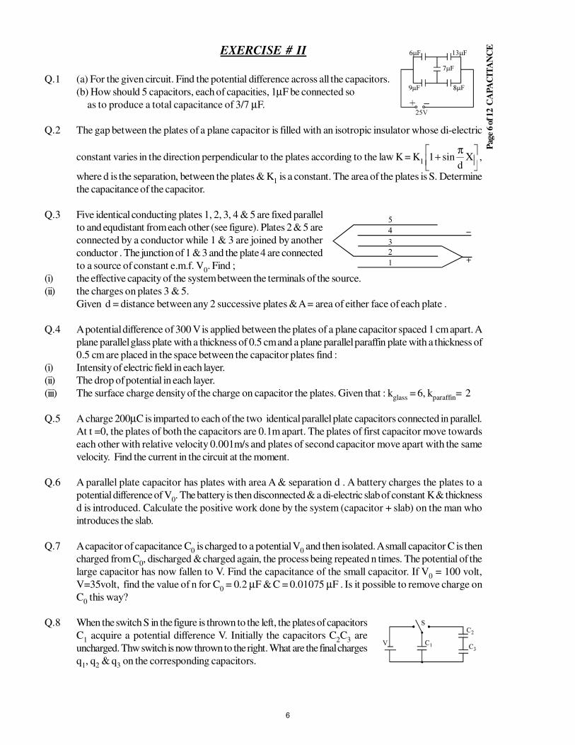
Q.1 (a) For the given circuit. Find the potential difference across all the capacitors.
(b) How should 5 capacitors, each of capacities, 1µF be connected so
as to produce a total capacitance of 3/7 µF.
Q.2 The gap between the plates of a plane capacitor is filled with an isotropic insulator whose di-electric
constant varies in the direction perpendicular to the plates according to the law K = K1
π+ X
dsin1 ,
where d is the separation, between the plates & K1 is a constant. The area of the plates is S. Determine
the capacitance of the capacitor.
Q.3 Five identical conducting plates 1, 2, 3, 4 & 5 are fixed parallel
to and equdistant from each other (see figure). Plates 2 & 5 are
connected by a conductor while 1 & 3 are joined by another
conductor . The junction of 1 & 3 and the plate 4 are connected
to a source of constant e.m.f. V0. Find ;
(i) the effective capacity of the system between the terminals of the source.
(ii) the charges on plates 3 & 5.
Given d = distance between any 2 successive plates & A = area of either face of each plate .
Q.4 A potential difference of 300 V is applied between the plates of a plane capacitor spaced 1 cm apart. A
plane parallel glass plate with a thickness of 0.5 cm and a plane parallel paraffin plate with a thickness of
0.5 cm are placed in the space between the capacitor plates find :
(i) Intensity of electric field in each layer.
(ii) The drop of potential in each layer.
(iii) The surface charge density of the charge on capacitor the plates. Given that : kglass
= 6, kparaffin
= 2
Q.5 A charge 200µC is imparted to each of the two identical parallel plate capacitors connected in parallel.
At t =0, the plates of both the capacitors are 0.1m apart. The plates of first capacitor move towards
each other with relative velocity 0.001m/s and plates of second capacitor move apart with the same
velocity. Find the current in the circuit at the moment.
Q.6 A parallel plate capacitor has plates with area A & separation d . A battery charges the plates to a
potential difference of V0. The battery is then disconnected & a di-electric slab of constant K & thickness
d is introduced. Calculate the positive work done by the system (capacitor + slab) on the man who
introduces the slab.
Q.7 A capacitor of capacitance C0 is charged to a potential V
0 and then isolated. A small capacitor C is then
charged from C0, discharged & charged again, the process being repeated n times. The potential of the
large capacitor has now fallen to V. Find the capacitance of the small capacitor. If V0 = 100 volt,
V=35volt, find the value of n for C0 = 0.2 µF & C = 0.01075 µF . Is it possible to remove charge on
C0 this way?
Q.8 When the switch S in the figure is thrown to the left, the plates of capacitors
C1 acquire a potential difference V. Initially the capacitors C
2C
3 are
uncharged. Thw switch is now thrown to the right. What are the final charges
q1, q
2 & q
3 on the corresponding capacitors.
6
Page
7 o
f 12 C
AP
AC
ITA
NC
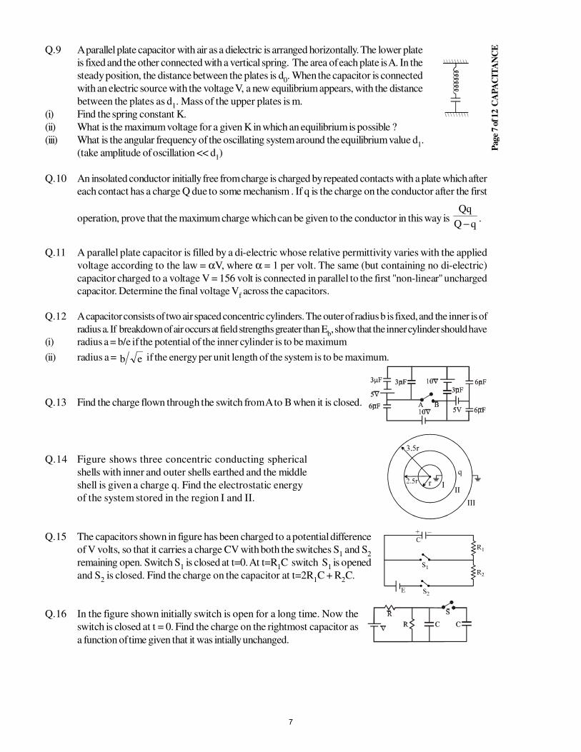
EQ.9 A parallel plate capacitor with air as a dielectric is arranged horizontally. The lower plate
is fixed and the other connected with a vertical spring. The area of each plate is A. In the
steady position, the distance between the plates is d0. When the capacitor is connected
with an electric source with the voltage V, a new equilibrium appears, with the distance
between the plates as d1. Mass of the upper plates is m.
(i) Find the spring constant K.
(ii) What is the maximum voltage for a given K in which an equilibrium is possible ?
(iii) What is the angular frequency of the oscillating system around the equilibrium value d1.
(take amplitude of oscillation << d1)
Q.10 An insolated conductor initially free from charge is charged by repeated contacts with a plate which after
each contact has a charge Q due to some mechanism . If q is the charge on the conductor after the first
operation, prove that the maximum charge which can be given to the conductor in this way is qQ
− .
Q.11 A parallel plate capacitor is filled by a di-electric whose relative permittivity varies with the applied
voltage according to the law = αV, where α = 1 per volt. The same (but containing no di-electric)
capacitor charged to a voltage V = 156 volt is connected in parallel to the first "non-linear" uncharged
capacitor. Determine the final voltage Vf across the capacitors.
Q.12 A capacitor consists of two air spaced concentric cylinders. The outer of radius b is fixed, and the inner is of
radius a. If breakdown of air occurs at field strengths greater than Eb, show that the inner cylinder should have
(i) radius a = b/e if the potential of the inner cylinder is to be maximum
(ii) radius a = eb if the energy per unit length of the system is to be maximum.
Q.13 Find the charge flown through the switch from A to B when it is closed.
Q.14 Figure shows three concentric conducting spherical
shells with inner and outer shells earthed and the middle
shell is given a charge q. Find the electrostatic energy
of the system stored in the region I and II.
Q.15 The capacitors shown in figure has been charged to a potential difference
of V volts, so that it carries a charge CV with both the switches S1 and S
2
remaining open. Switch S1 is closed at t=0. At t=R
1C switch S
1 is opened
and S2 is closed. Find the charge on the capacitor at t=2R
1C + R
2C.
Q.16 In the figure shown initially switch is open for a long time. Now the
switch is closed at t = 0. Find the charge on the rightmost capacitor as
a function of time given that it was intially unchanged.
7
Page
8 o
f 12 C
AP
AC
ITA
NC
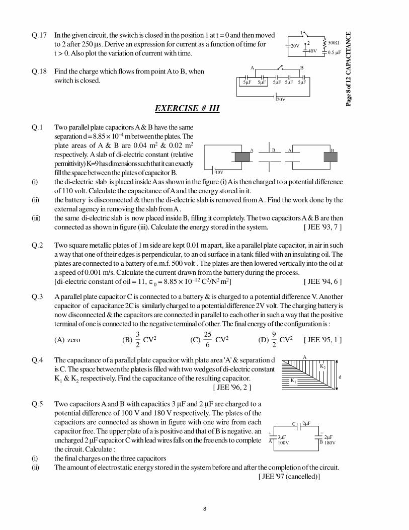
EQ.17 In the given circuit, the switch is closed in the position 1 at t = 0 and then moved
to 2 after 250 µs. Derive an expression for current as a function of time for
t > 0. Also plot the variation of current with time.
Q.18 Find the charge which flows from point A to B, when
switch is closed.
EXERCISE # III
Q.1 Two parallel plate capacitors A & B have the same
separation d = 8.85 × 10⁻⁴ m between the plates. The
plate areas of A & B are 0.04 m2 & 0.02 m2
respectively. A slab of di-electric constant (relative
permittivity) K=9 has dimensions such that it can exactly
fill the space between the plates of capacitor B.
(i) the di-electric slab is placed inside A as shown in the figure (i) A is then charged to a potential difference
of 110 volt. Calculate the capacitance of A and the energy stored in it.
(ii) the battery is disconnected & then the di-electric slab is removed from A . Find the work done by the
external agency in removing the slab from A .
(iii) the same di-electric slab is now placed inside B, filling it completely. The two capacitors A & B are then
connected as shown in figure (iii). Calculate the energy stored in the system. [ JEE '93, 7 ]
Q.2 Two square metallic plates of 1 m side are kept 0.01 m apart, like a parallel plate capacitor, in air in such
a way that one of their edges is perpendicular, to an oil surface in a tank filled with an insulating oil. The
plates are connected to a battery of e.m.f. 500 volt . The plates are then lowered vertically into the oil at
a speed of 0.001 m/s. Calculate the current drawn from the battery during the process.
[di-electric constant of oil = 11, ∈0 = 8.85 × 10⁻¹² C2/N2 m2] [ JEE '94, 6 ]
Q.3 A parallel plate capacitor C is connected to a battery & is charged to a potential difference V. Another
capacitor of capacitance 2C is similarly charged to a potential difference 2V volt. The charging battery is
now disconnected & the capacitors are connected in parallel to each other in such a way that the positive
terminal of one is connected to the negative terminal of other. The final energy of the configuration is :
(A) zero (B) 2
3 CV2 (C)
6
25 CV2 (D)
2
9 CV2 [ JEE '95, 1 ]
Q.4 The capacitance of a parallel plate capacitor with plate area 'A' & separation d
is C. The space between the plates is filled with two wedges of di-electric constant
K1 & K
2 respectively. Find the capacitance of the resulting capacitor.
[ JEE '96, 2 ]
Q.5 Two capacitors A and B with capacities 3 µF and 2 µF are charged to a
potential difference of 100 V and 180 V respectively. The plates of the
capacitors are connected as shown in figure with one wire from each
capacitor free. The upper plate of a is positive and that of B is negative. an
uncharged 2 µF capacitor C with lead wires falls on the free ends to complete
the circuit. Calculate :
(i) the final charges on the three capacitors
(ii) The amount of electrostatic energy stored in the system before and after the completion of the circuit.
[ JEE '97 (cancelled)]
8
Page
9 o
f 12 C
AP
AC
ITA
NC
EQ.6 An electron enters the region between the plates of a parallel plate capacitor at a point equidistant from
either plate. The capacitor plates are 2 × 10⁻² m apart & 10−1 m long . A potential difference of 300 volt
is kept across the plates. Assuming that the initial velocity of the electron is parallel to the capacitor
plates, calculate the largest value of the velocity of the electron so that they do not fly out of the capacitor
at the other end. [ JEE '97, 5 ]
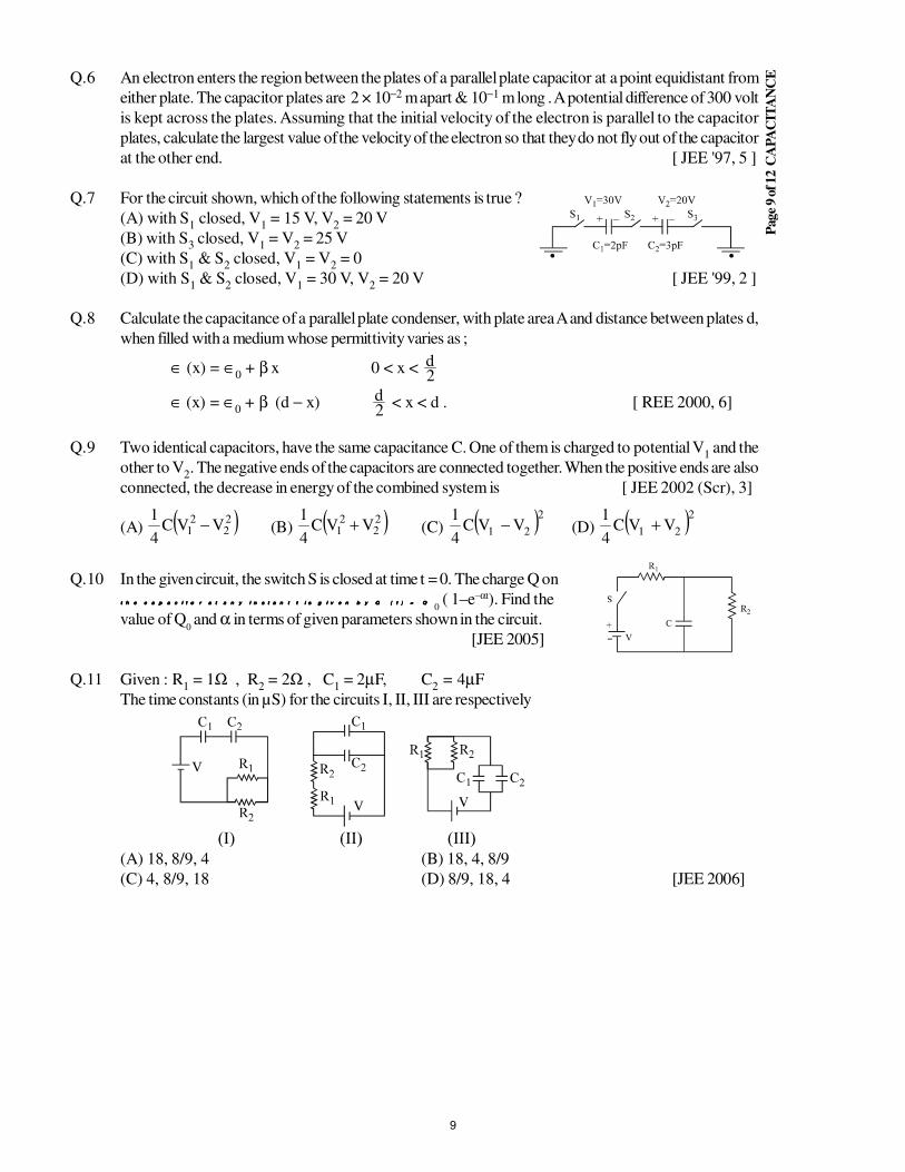
Q.7 For the circuit shown, which of the following statements is true ?
(A) with S1 closed, V
1 = 15 V, V
2 = 20 V
(B) with S3 closed, V
1 = V
2 = 25 V
(C) with S1 & S
2 closed, V
1 = V
2 = 0
(D) with S1 & S
2 closed, V
1 = 30 V, V
2 = 20 V [ JEE '99, 2 ]
Q.8 Calculate the capacitance of a parallel plate condenser, with plate area A and distance between plates d,
when filled with a medium whose permittivity varies as ;
∈ (x) = ∈0 + β x 0 < x <
2d
∈ (x) = ∈0 + β (d − x)
2d < x < d . [ REE 2000, 6]
Q.9 Two identical capacitors, have the same capacitance C. One of them is charged to potential V1 and the
other to V2. The negative ends of the capacitors are connected together. When the positive ends are also
connected, the decrease in energy of the combined system is [ JEE 2002 (Scr), 3]
(A) ( )22
21 VVC
4
1− (B) ( )2
22
1 VVC4
1+ (C) ( )221 VVC
4
1− (D) ( )221 VVC
4
1+
Q.10 In the given circuit, the switch S is closed at time t = 0. The charge Q on
t h e c a p a c i t o r a t a n y i n s t a n t t i s g i v e n b y Q ( t ) = Qt h e c a p a c i t o r a t a n y i n s t a n t t i s g i v e n b y Q ( t ) = Qt h e c a p a c i t o r a t a n y i n s t a n t t i s g i v e n b y Q ( t ) = Qt h e c a p a c i t o r a t a n y i n s t a n t t i s g i v e n b y Q ( t ) = Q0 ( 1–e–αt). Find the
value of Q0 and α in terms of given parameters shown in the circuit.
[JEE 2005]
Q.11 Given : R1 = 1Ω , R
2 = 2Ω , C
1 = 2µF, C
2 = 4µF
The time constants (in µS) for the circuits I, II, III are respectively
(A) 18, 8/9, 4 (B) 18, 4, 8/9
(C) 4, 8/9, 18 (D) 8/9, 18, 4 [JEE 2006]
9
Page
10 o
f 12 C
APA
CIT
AN
CEANSWER KEY
EXERCISE # I
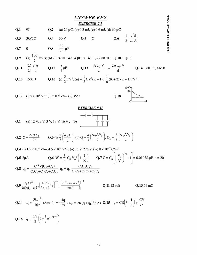
Q.1 9J Q.2 (a) 20 µC, (b) 0.3 mJ, (c) 0.6 mJ. (d) 60 µC
Q.3 3Q/2C Q.4 30 V Q.5 C Q.61
2
q d
A
2
0∈
Q.7 0 Q.823
32µF
Q.9 (a) 100
7 volts; (b) 28.56 µC, 42.84 µC, 71.4 µC, 22.88 µC Q.10 10 µC
Q.1125
24
0ε A
dQ.12 F
3
8µ Q.13
d
VA 0∈ , –
d
VA2 0∈Q.14 60 µc , A to B
Q.15 150 µJ Q.16 (i) 3
2CV2; (ii) –
1
2CV2(K – 1);
1
6(K + 2) (K – 1)CV2 ;
Q.17 (i) 5 x 10⁴ V/m , 3 x 10⁴ V/m; (ii) 35/9 Q.18
EXERCISE # II
Q.1 (a) 12 V, 9 V, 3 V, 13 V, 16 V , (b)
Q.2 C = d2
KS 1π∈Q.3 (i)
5
3
∈
d
A0 ; (ii) Q3=
4
3
∈
d
AVa0, Q
5 =
3
2
∈
d
AVa0
Q.4 (i) 1.5 × 10⁴ V/m, 4.5 × 10⁴ V/m, (ii) 75 V, 225 V, (iii) 8 × 10⁻⁷ C/m2
Q.5 2µA Q.6 W = 1
2C
0 V
02
−K
11 Q.7 C = C
0
−
1
V
Vn/1
0 = 0.01078 µF, n = 20
Q.8 q1 =
( )313221
322
1
CCCCCC
CCVC
+++
q2 = q
3133221
321
CCCCCC
VCCC
++
Q.9 ( )
2/3
0010
21
20 d
3
2
A
K,
ddd2
AV
ε−
ε,
2/1
31
20
31
dm
AVKd
∈−Q.11 12 volt Q.13 69 mC
Q.14 UI =
r10
kq32
1 where
25
q4q
1−= ; U
II = r35)qq(K2
21+ Q.15 q = CE
−e
11 + 2e
CV
Q.16 q =
− − RC/te2
11
2
CV
10
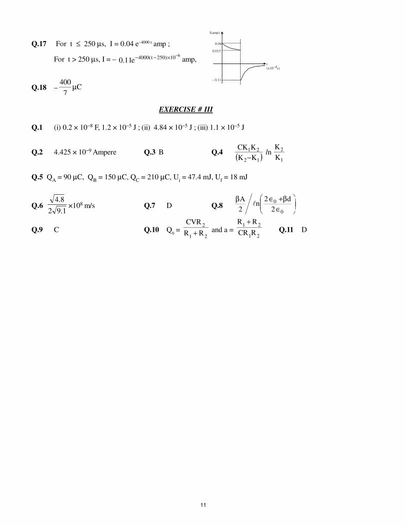
Q.17 For t ≤ 250 µs, I = 0.04 e–4000 t amp ;
For t > 250 µs, I = – 610)250t(4000e11.0
−×−− amp,t(x10–4s)
– 0.11
0.015
0.04
I(amp)
Q.18 –400
7µC
EXERCISE # III
Q.1 (i) 0.2 × 10⁻⁸ F, 1.2 × 10⁻⁵ J ; (ii) 4.84 × 10⁻⁵ J ; (iii) 1.1 × 10⁻⁵ J
Q.2 4.425 × 10⁻⁹ Ampere Q.3 B Q.4 ( )12
21
KK
KKC
− ln
1
2
K
K
Q.5 QA = 90 µC, Q
B = 150 µC, Q
C = 210 µC, U
i = 47.4 mJ, U
f = 18 mJ
Q.6 1.92
8.4×10⁸ m/s Q.7 D Q.8
∈β+∈β
0
0
2
d2n
2
A
Q.9 C Q.10 Q0 =
21
2
RR
CVR
+ and a =21
21
RCR
RR +Q.11 D
11
STUDY PACKAGE
Target: IIT-JEE (Advanced)
SUBJECT: PHYSICS
TOPIC: XII P3. Current Electricity
Index:
1. Key Concepts
2. Exercise I
3. Exercise II
4. Exercise III
5. Exercise IV
6. Answer Key
7. 34 Yrs. Que. from IIT-JEE
8. 10 Yrs. Que. from AIEEE
1
Page
2 o
f 16 C
UR
RE
NT
FL
EC
TR
YC
ITY
CURRENT ELECTRICITY
1. ELECTRIC CURRENT :
Electric charges in motion constitute an electric current. Any medium having practically free electric
charges , free to migrate is a conductor of electricity. The electric charge flows from higher potential
energy state to lower potential energy state. Positive charge flows from higher to lower potential and
negative charge flows from lower to higher. Metals such as gold, silver, copper, aluminium etc. are good
conductors.
2. ELECTRIC CURRENT IN A CONDUCTOR :
In absence of potential difference across a conductor no net current flows through a corss section.
When a potential difference is applied across a conductor the charge carriers (electrons in case of
metallic conductors) flow in a definite direction which constitutes a net current in it . These electrons are
not accelerated by electric field in the conductor produced by potential difference across the conductor.
They move with a constant drift velocity . The direction of current is along the flow of positive charge (or
opposite to flow of negative charge). i = nvdeA, where V
d = drift velocity .
3. CHARGE AND CURRENT :
The strength of the current i is the rate at which the electric charges are flowing. If a charge Q coulomb
passes through a given cross section of the conductor in t second the current I through the conductor is
given by I = Q
t =
Coulomb
ondsec =
Q
t ampere .
Ampere is the unit of current . If i is not constant then i = dt
dq, where dq is net charge transported at
a section in time dt.
In a current carrying conductor we can define a vector which gives the direction as current per unit
normal, cross sectional area.
Thus J =
I
Sn or I =
J ·
S
Where n is the unit vector in the direction of the flow of current.
For random J or S, we use I = J ds→
⋅→
∫4. RELATION IN J, E AND ν
D :
In conductors drift vol. of electrons is proportional to the electric field in side the conductor
as – ν d = µE
where µ is the mobility of electrons
current density is given as J = I
A= ne ν d
= ne(µE) = σE
where σ = neµ is called conductivity of material and we can also write ρ = 1
σ → resistivity
of material. Thus E = ρ J. It is called as differential form of Ohm's Law.
5. SOURCES OF POTENTIAL DIFFERENCE & ELECTROMOTIVE FORCE :
Dry cells , secondary cells , generator and thermo couple are the devices used for producing potential
difference in an electric circuit. The potential difference between the two terminals of a source when no
energy is drawn from it is called the " Electromotive force" or " EMF " of the source. The unit of
potential difference is volt.
1 volt = 1 Amphere × 1 Ohm.
2
Page
3 o
f 16 C
UR
RE
NT
FL
EC
TR
YC
ITY
6. ELECTRICAL RESISTANCE :
The property of a substance which opposes the flow of electric current through it is termed as electrical
resistance. Electrical resistance depends on the size, geometery, temperature and internal structure of the
conductor.
7. LAW OF RESISTANCE :
The resistance R offered by a conductor depends on the following factors :
R α L (length of the conductor) ; R A
lα (cross section area of the conductor)
at a given temperature R = A
lρ .
Where ρ is the resistivity of the material of the conductor at the given temperature . It is also known as
specific resistance of the material .
8. DEPENDENCE OF RESISTANCE ON TEMPERATURE :
The resistance of most conductors and all pure metals increases with temperature , but there are a few in
which resistance decreases with temperature . If Ro & R be the resistance of a conductor at 0º C and θº
C , then it is found that R = Ro (1 + α θ) .
Here we assume that the dimensions of resistance does not change with temperature if expansion
coefficient of material is considerable. Then instead of resistance we use same property for
resistivity as ρ = ρ0 (1 + αθ)
The materials for which resistance decreases with temperature, the temperature coefficient of
resistance is negative.
Where α is called the temperature co-efficient of resistance . The unit of α is K− 1 of ºC −1 reciprocal of
resistivity is called conductivity and reciprocal of resistance is called conductance (G) . S.I. unit of G is
ohm.
9. OHM'S LAW :
Ohm's law is the most fundamental of all the laws in electricity . It says that the current through the cross
section or the conductor is proportional to the applied potential difference under the given physical
condition . V = R I . Ohm's law is applicable to only metalic conductors .
10. KRICHHOFF'S LAW'S :
I - Law (Junction law or Nodal Analysis) :This law is based on law of conservation of charge . It
states that " The algebric sum of the currents meeting at a point is zero " or total currents entering a
junction equals total current leaving the junction .
Σ Iin
= Σ Iout
. It is also known as KCL (Kirchhoff's current law) .
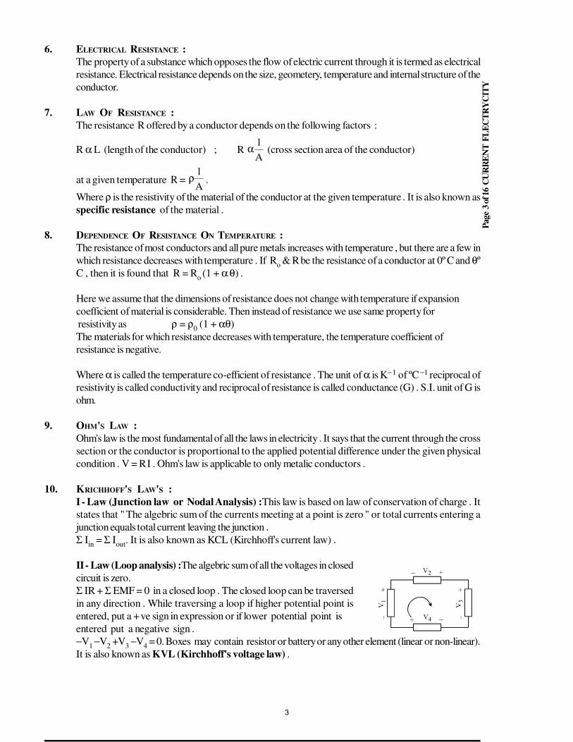
II - Law (Loop analysis) :The algebric sum of all the voltages in closed
circuit is zero.
Σ IR + Σ EMF = 0 in a closed loop . The closed loop can be traversed
in any direction . While traversing a loop if higher potential point is
entered, put a + ve sign in expression or if lower potential point is
entered put a negative sign .
−V1 −V
2 +V
3 −V
4 = 0. Boxes may contain resistor or battery or any other element (linear or non-linear).
It is also known as KVL (Kirchhoff's voltage law) .
3
Page
4 o
f 16 C
UR
RE
NT
FL
EC
TR
YC
ITY
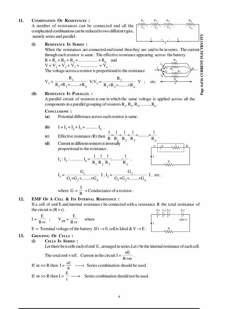
11. COMBINATION OF RESISTANCES :
A number of resistances can be connected and all the
complecated combinations can be reduced to two different types,
namely series and parallel .
(i) RESISTANCE IN SERIES :
When the resistances are connected end toend then they are said to be in series . The current
through each resistor is same . The effective resistance appearing across the battery .
R = R1 + R
2 + R
3 + ................ + R
nand
V = V1 + V
2 + V
3 + ................ + V
n .
The voltage across a resistor is proportional to the resistance
V1 =
n21
1
R.........RR
R
+++V;V
2 =
n21
2
R.........RR
R
+++ V ; etc
(ii) RESISTANCE IN PARALLEL :
A parallel circuit of resistors is one in which the same voltage is applied across all the
components in a parallel grouping of resistors R1, R
2, R
3, ........, R
n .
CONCLUSIONS :
(a) Potential difference across each resistor is same .
(b) I = I1
+ I2
+ I3
+ .......... In .
(c) Effective resistance (R) then n321
R
1..........
R
1
R
1
R
1
R
1++++= .
(d) Current in different resistors is inversally
proportional to the resistance .
I1 : I
2 : ........... I
n =
n321R
1:..........:
R
1:
R
1:
R
1 .
I1 =
n21
1
G.........GG
G
+++I , I
2 =
n21
2
G.........GG
G
+++ I , etc .
where G = R
I = Conductance of a resistor .
12. EMF OF A CELL & ITS INTERNAL RESISTANCE :
If a cell of emf E and internal resistance r be connected with a resistance R the total resistance of
the circuit is (R + r) .
I = rR
E
+ ; V
AB =
rR
E
+where
E = Terminal voltage of the battery .If r → 0, cell is Ideal & V → E .
13. GROUPING OF CELLS :
(i) CELLS IN SERIES :
Let there be n cells each of emf E , arranged in series.Let r be the internal resistance of each cell.
The total emf = n E . Current in the circuit I = nrR
nE
+ .
If nr << R then I = nE
R → Series combination should be used .
If nr >> R then I = r
E→ Series combination should not be used .
4
Page
5 o
f 16 C
UR
RE
NT
FL
EC
TR
YC
ITY
(ii) CELLS IN PARALLEL :
If m cells each of emf E & internal resistance r be connected in parallel and if this
combination be connected to an external resistance then the emf of the circuit = E .
Internal resistance of the circuit = m
r .
I =
mrR
E
+ =
rmR
mE
+ .
If mR << r ; I = r
mE→ Parallel combination should be used .
If mR >> r ; I = R
E→ Parallel combination should not be used .
(iii) CELLS IN MULTIPLE ARC :
mn = number of identical cells .
n = number of rows
m = number of cells in each rows .
The combination of cells is equivalent to single cell of :
(a) emf = mE & (b) internal resistance = n
mr
Current I =
nmrR
mE
+ . For maximum current nR = mr or
R = n
mr = internal resistance of battery .
Imax
=R2
mE
r2
nE= .
WHEAT STONE NETWORK :
When current through the galvanometer is zero (null point or balance
point) Q
P =
S
R. When PS > QR; V
C < V
D & PS <QR ; V
C > V
D or
PS = QR ⇒ products of opposite arms are equal. Potential difference
between C & D at null point is zero . The null point is not affected by
resistance of G & E. It is not affected even if the positions of G & E are
inter changed. ICD
α (QR − PS) .
14. POTENTIOMETER :
A potentiometer is a linear conductor of uniform cross-section with a steady current set up in it. This
maintains a uniform potential gradient along the length of the wire . Any potential difference which is less
then the potential difference maintained across the potentiometer wire can be measured using this . The
potentiometer equation is
2
1
2
1
I
I
E
E= .
5
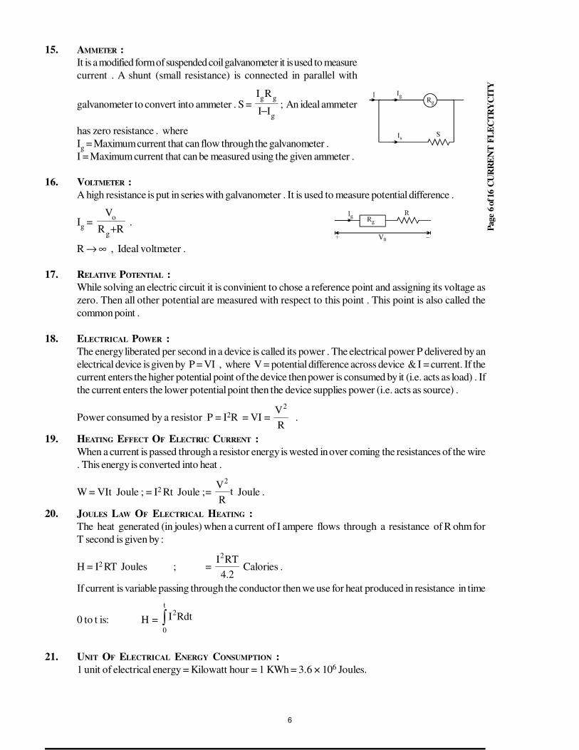
Page
6 o
f 16 C
UR
RE
NT
FL
EC
TR
YC
ITY
15. AMMETER :
It is a modified form of suspended coil galvanometer it is used to measure
current . A shunt (small resistance) is connected in parallel with
galvanometer to convert into ammeter . S = g
gg
II
RI
−; An ideal ammeter
has zero resistance . where
Ig = Maximum current that can flow through the galvanometer .
I = Maximum current that can be measured using the given ammeter .
16. VOLTMETER :
A high resistance is put in series with galvanometer . It is used to measure potential difference .
Ig =
RR
V
g
o
+ .
R → ∞ , Ideal voltmeter .
17. RELATIVE POTENTIAL :
While solving an electric circuit it is convinient to chose a reference point and assigning its voltage as
zero. Then all other potential are measured with respect to this point . This point is also called the
common point .
18. ELECTRICAL POWER :
The energy liberated per second in a device is called its power . The electrical power P delivered by an
electrical device is given by P = VI , where V = potential difference across device & I = current. If the
current enters the higher potential point of the device then power is consumed by it (i.e. acts as load) . If
the current enters the lower potential point then the device supplies power (i.e. acts as source) .
Power consumed by a resistor P = I2R = VI = R
V2
.
19. HEATING EFFECT OF ELECTRIC CURRENT :
When a current is passed through a resistor energy is wested in over coming the resistances of the wire
. This energy is converted into heat .
W = VIt Joule ; = I2 Rt Joule ;= tR
V2
Joule .
20. JOULES LAW OF ELECTRICAL HEATING :
The heat generated (in joules) when a current of I ampere flows through a resistance of R ohm for
T second is given by :
H = I2 RT Joules ; = 2.4
RTI2
Calories .
If current is variable passing through the conductor then we use for heat produced in resistance in time
0 to t is: H = ∫t
0
2RdtI
21. UNIT OF ELECTRICAL ENERGY CONSUMPTION :
1 unit of electrical energy = Kilowatt hour = 1 KWh = 3.6 × 10⁶ Joules.
6
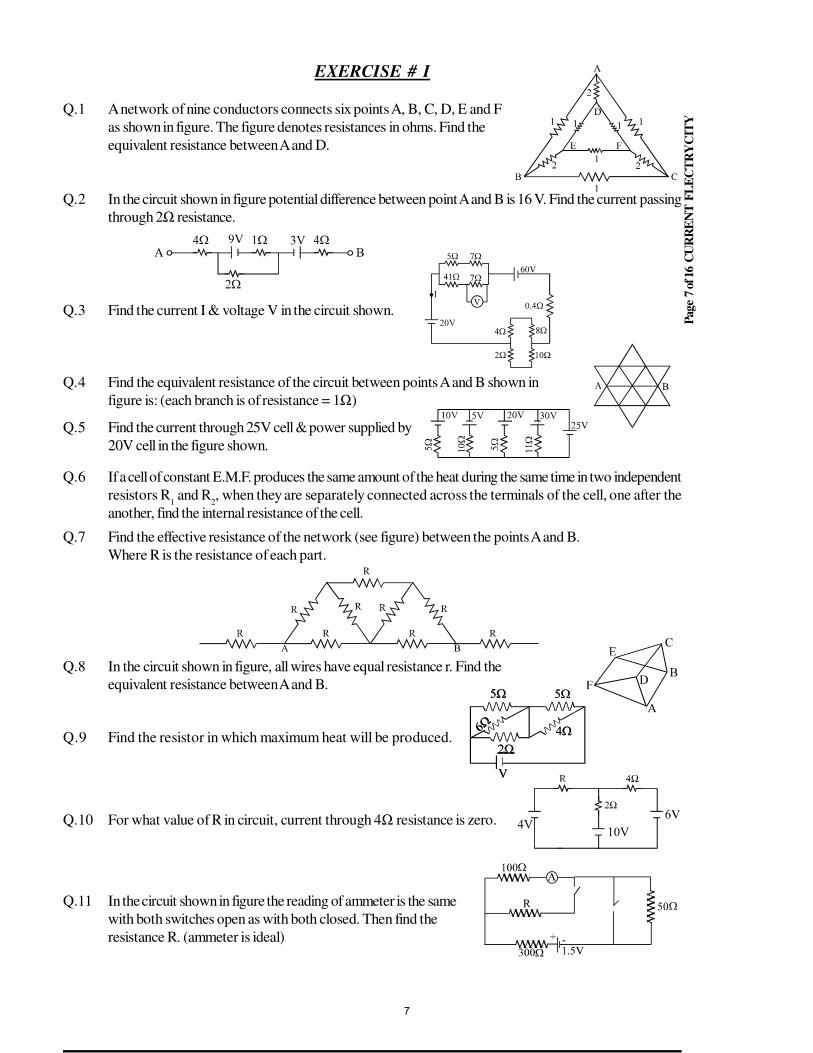
Page
7 o
f 16 C
UR
RE
NT
FL
EC
TR
YC
ITY
EXERCISE # I
Q.1 A network of nine conductors connects six points A, B, C, D, E and F
as shown in figure. The figure denotes resistances in ohms. Find the
equivalent resistance between A and D.
Q.2 In the circuit shown in figure potential difference between point A and B is 16 V. Find the current passing
through 2Ω resistance.
Q.3 Find the current I & voltage V in the circuit shown.
Q.4 Find the equivalent resistance of the circuit between points A and B shown in
figure is: (each branch is of resistance = 1Ω)
Q.5 Find the current through 25V cell & power supplied by
20V cell in the figure shown.
Q.6 If a cell of constant E.M.F. produces the same amount of the heat during the same time in two independent
resistors R1 and R
2, when they are separately connected across the terminals of the cell, one after the
another, find the internal resistance of the cell.
Q.7 Find the effective resistance of the network (see figure) between the points A and B.
Where R is the resistance of each part.
Q.8 In the circuit shown in figure, all wires have equal resistance r. Find the
equivalent resistance between A and B.
Q.9 Find the resistor in which maximum heat will be produced.
Q.10 For what value of R in circuit, current through 4Ω resistance is zero.
Q.11 In the circuit shown in figure the reading of ammeter is the same
with both switches open as with both closed. Then find the
resistance R. (ammeter is ideal)
7
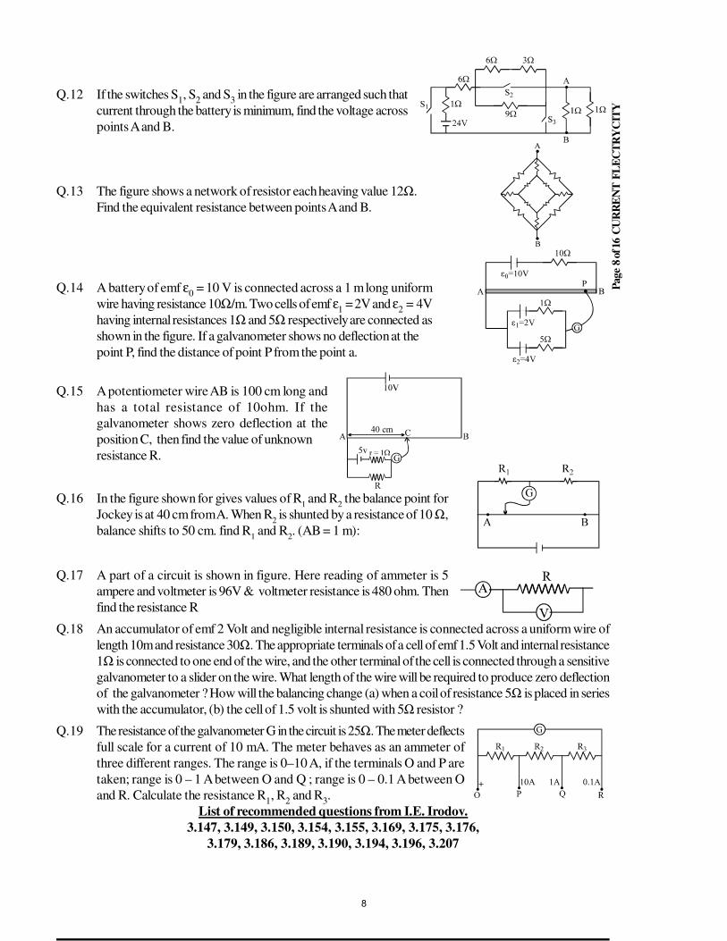
Page
8 o
f 16 C
UR
RE
NT
FL
EC
TR
YC
ITY
Q.12 If the switches S1, S
2 and S
3 in the figure are arranged such that
current through the battery is minimum, find the voltage across
points A and B.
Q.13 The figure shows a network of resistor each heaving value 12Ω.
Find the equivalent resistance between points A and B.
Q.14 A battery of emf ε0 = 10 V is connected across a 1 m long uniform
wire having resistance 10Ω/m. Two cells of emf ε1 = 2V and ε
2 = 4V
having internal resistances 1Ω and 5Ω respectively are connected as
shown in the figure. If a galvanometer shows no deflection at the
point P, find the distance of point P from the point a.
Q.15 A potentiometer wire AB is 100 cm long and
has a total resistance of 10ohm. If the
galvanometer shows zero deflection at the
position C, then find the value of unknown
resistance R.
Q.16 In the figure shown for gives values of R1 and R
2 the balance point for
Jockey is at 40 cm from A. When R2 is shunted by a resistance of 10 Ω,
balance shifts to 50 cm. find R1 and R
2. (AB = 1 m):
Q.17 A part of a circuit is shown in figure. Here reading of ammeter is 5
ampere and voltmeter is 96V & voltmeter resistance is 480 ohm. Then
find the resistance R
Q.18 An accumulator of emf 2 Volt and negligible internal resistance is connected across a uniform wire of
length 10m and resistance 30Ω. The appropriate terminals of a cell of emf 1.5 Volt and internal resistance
1Ω is connected to one end of the wire, and the other terminal of the cell is connected through a sensitive
galvanometer to a slider on the wire. What length of the wire will be required to produce zero deflection
of the galvanometer ? How will the balancing change (a) when a coil of resistance 5Ω is placed in series
with the accumulator, (b) the cell of 1.5 volt is shunted with 5Ω resistor ?
Q.19 The resistance of the galvanometer G in the circuit is 25Ω. The meter deflects
full scale for a current of 10 mA. The meter behaves as an ammeter of
three different ranges. The range is 0–10 A, if the terminals O and P are
taken; range is 0 – 1 A between O and Q ; range is 0 – 0.1 A between O
and R. Calculate the resistance R1, R
2 and R
3.
List of recommended questions from I.E. Irodov.
3.147, 3.149, 3.150, 3.154, 3.155, 3.169, 3.175, 3.176,
3.179, 3.186, 3.189, 3.190, 3.194, 3.196, 3.207
8
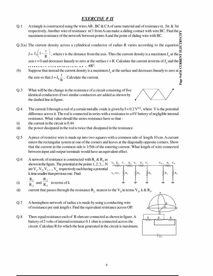
Page
9 o
f 16 C
UR
RE
NT
FL
EC
TR
YC
ITY
EXERCISE # II
Q.1 A triangle is constructed using the wires AB , BC & CA of same material and of resistance α, 2α & 3αrespectively. Another wire of resistance α/3
from A can make a sliding contact with wire BC. Find the
maximum resistance of the network between points A and the point of sliding wire with BC.
Q.2(a) The current density across a cylindrical conductor of radius R varies according to the equation
J =
−R
r1J0 , where r is the distance from the axis. Thus the current density is a maximum J
o at the
axis r = 0 and decreases linearly to zero at the surface r = R. Calculate the current in terms of Jo and the
c o n d u c t o r ’ s c r o s s s e c t i o n a l a r e a i s A =c o n d u c t o r ’ s c r o s s s e c t i o n a l a r e a i s A =c o n d u c t o r ’ s c r o s s s e c t i o n a l a r e a i s A =c o n d u c t o r ’ s c r o s s s e c t i o n a l a r e a i s A = πR2.
(b) Suppose that instead the current density is a maximum Jo at the surface and decreases linearly to zero at
the axis so that J = J0 R
r. Calculate the current.
Q.3 What will be the change in the resistance of a circuit consisting of five
identical conductors if two similar conductors are added as shown by
the dashed line in figure.
Q.4 The current I through a rod of a certain metallic oxide is given by I = 0.2 V5/2, where V is the potential
difference across it. The rod is connected in series with a resistance to a 6V battery of negligible internal
resistance. What value should the series resistance have so that :
(i) the current in the circuit is 0.44
(ii) the power dissipated in the rod is twice that dissipated in the resistance.
Q.5 A piece of resistive wire is made up into two squares with a common side of length 10 cm. A currant
enters the rectangular system at one of the corners and leaves at the diagonally opposite corners. Show
that the current in the common side is 1/5th of the entering current. What length of wire connected
between input and output terminals would have an equivalent effect.
Q.6 A network of resistance is constructed with R1 & R
2 as
shown in the figure. The potential at the points 1, 2, 3,.., N
are V1, V
2, V
3 , .., V
n respectively each having a potential
k time smaller than previous one. Find:
(i)2
1
R
R and
3
2
R
R in terms of k
(ii) current that passes through the resistance R2 nearest to the V
0 in terms V
0, k & R
3.
Q.7 A hemisphere network of radius a is made by using a conducting wire
of resistance per unit length r. Find the equivalent resistance across OP.
Q.8 Three equal resistance each of R ohm are connected as shown in figure. A
battery of 2 volts of internal resistance 0.1 ohm is connected across the
circuit. Calculate R for which the heat generated in the circuit is maximum.
9
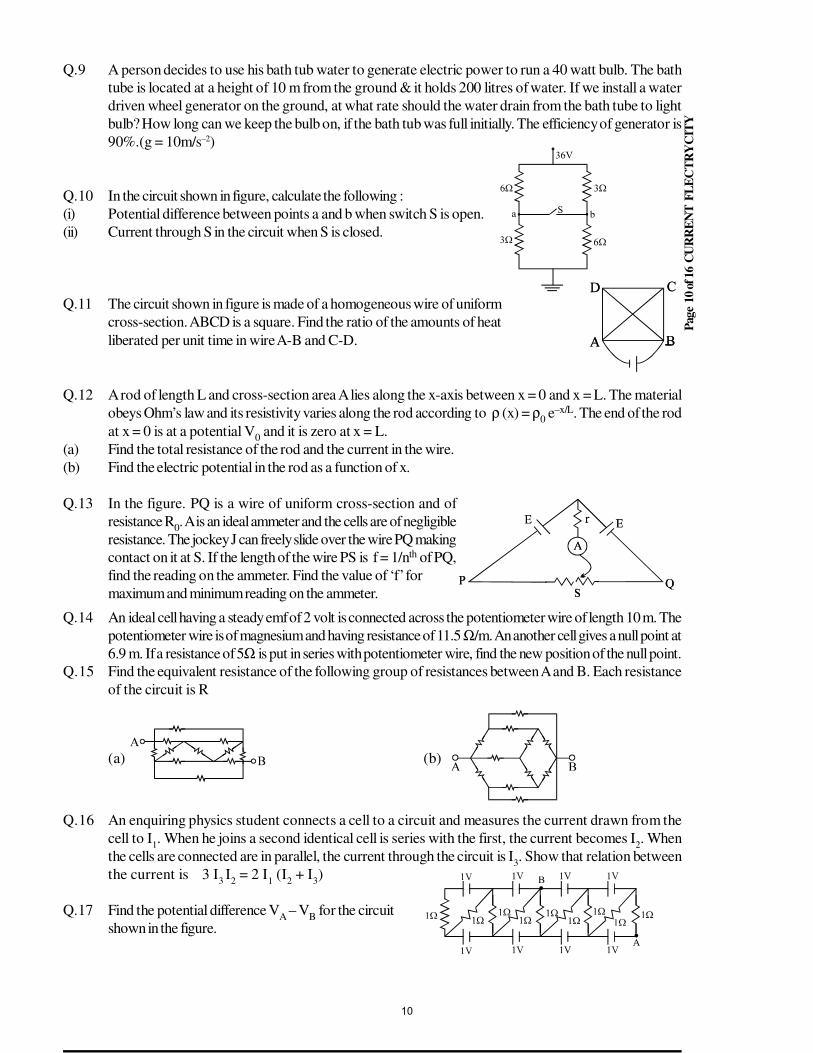
Pag
e 1
0 o
f 16
CU
RR
EN
T F
LE
CT
RY
CIT
Y
Q.9 A person decides to use his bath tub water to generate electric power to run a 40 watt bulb. The bath
tube is located at a height of 10 m from the ground & it holds 200 litres of water. If we install a water
driven wheel generator on the ground, at what rate should the water drain from the bath tube to light
bulb? How long can we keep the bulb on, if the bath tub was full initially. The efficiency of generator is
90%.(g = 10m/s–2)
Q.10 In the circuit shown in figure, calculate the following :
(i) Potential difference between points a and b when switch S is open.
(ii) Current through S in the circuit when S is closed.
Q.11 The circuit shown in figure is made of a homogeneous wire of uniform
cross-section. ABCD is a square. Find the ratio of the amounts of heat
liberated per unit time in wire A-B and C-D.
Q.12 A rod of length L and cross-section area A lies along the x-axis between x = 0 and x = L. The material
obeys Ohm’s law and its resistivity varies along the rod according to ρ (x) = ρ0 e–x/L. The end of the rod
at x = 0 is at a potential V0 and it is zero at x = L.
(a) Find the total resistance of the rod and the current in the wire.
(b) Find the electric potential in the rod as a function of x.
Q.13 In the figure. PQ is a wire of uniform cross-section and of
resistance R0. A is an ideal ammeter and the cells are of negligible
resistance. The jockey J can freely slide over the wire PQ making
contact on it at S. If the length of the wire PS is f = 1/nth of PQ,
find the reading on the ammeter. Find the value of ‘f’ for
maximum and minimum reading on the ammeter.
Q.14 An ideal cell having a steady emf of 2 volt is connected across the potentiometer wire of length 10 m. The
potentiometer wire is of magnesium and having resistance of 11.5 Ω/m. An another cell gives a null point at
6.9 m. If a resistance of 5Ω is put in series with potentiometer wire, find the new position of the null point.
Q.15 Find the equivalent resistance of the following group of resistances between A and B. Each resistance
of the circuit is R
(a) (b)
Q.16 An enquiring physics student connects a cell to a circuit and measures the current drawn from the
cell to I1. When he joins a second identical cell is series with the first, the current becomes I
2. When
the cells are connected are in parallel, the current through the circuit is I3. Show that relation between
the current is 3 I3 I
2 = 2 I
1 (I
2 + I
3)
Q.17 Find the potential difference VA – V
B for the circuit
shown in the figure.
10
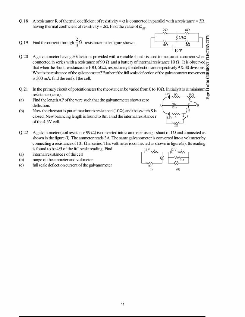
Pag
e 1
1 o
f 16
CU
RR
EN
T F
LE
CT
RY
CIT
Y
Q.18 A resistance R of thermal coefficient of resistivity = α is connected in parallel with a resistance = 3R,
having thermal coefficient of resistivity = 2α. Find the value of αeff
.
Q.19 Find the current through Ω3
2 resistance in the figure shown.
Q.20 A galvanometer having 50 divisions provided with a variable shunt s is used to measure the current when
connected in series with a resistance of 90 Ω and a battery of internal resistance 10 Ω. It is observed
that when the shunt resistance are 10Ω, 50Ω, respectively the deflection are respectively 9 & 30 divisions.
What is the resistance of the galvanometer? Further if the full scale deflection of the galvanometer movement
is 300 mA, find the emf of the cell.
Q.21 In the primary circuit of potentiometer the rheostat can be varied from 0 to 10Ω. Initially it is at minimum
resistance (zero).
(a) Find the length AP of the wire such that the galvanometer shows zero
deflection.
(b) Now the rheostat is put at maximum resistance (10Ω) and the switch S is
closed. New balancing length is found to 8m. Find the internal resistance r
of the 4.5V cell.
Q.22 A galvanometer (coil resistance 99 Ω) is converted into a ammeter using a shunt of 1Ω and connected as
shown in the figure (i). The ammeter reads 3A. The same galvanometer is converted into a voltmeter by
connecting a resistance of 101 Ω in series. This voltmeter is connected as shown in figure(ii). Its reading
is found to be 4/5 of the full scale reading. Find
(a) internal resistance r of the cell
(b) range of the ammeter and voltmeter
(c) full scale deflection current of the galvanometer
11
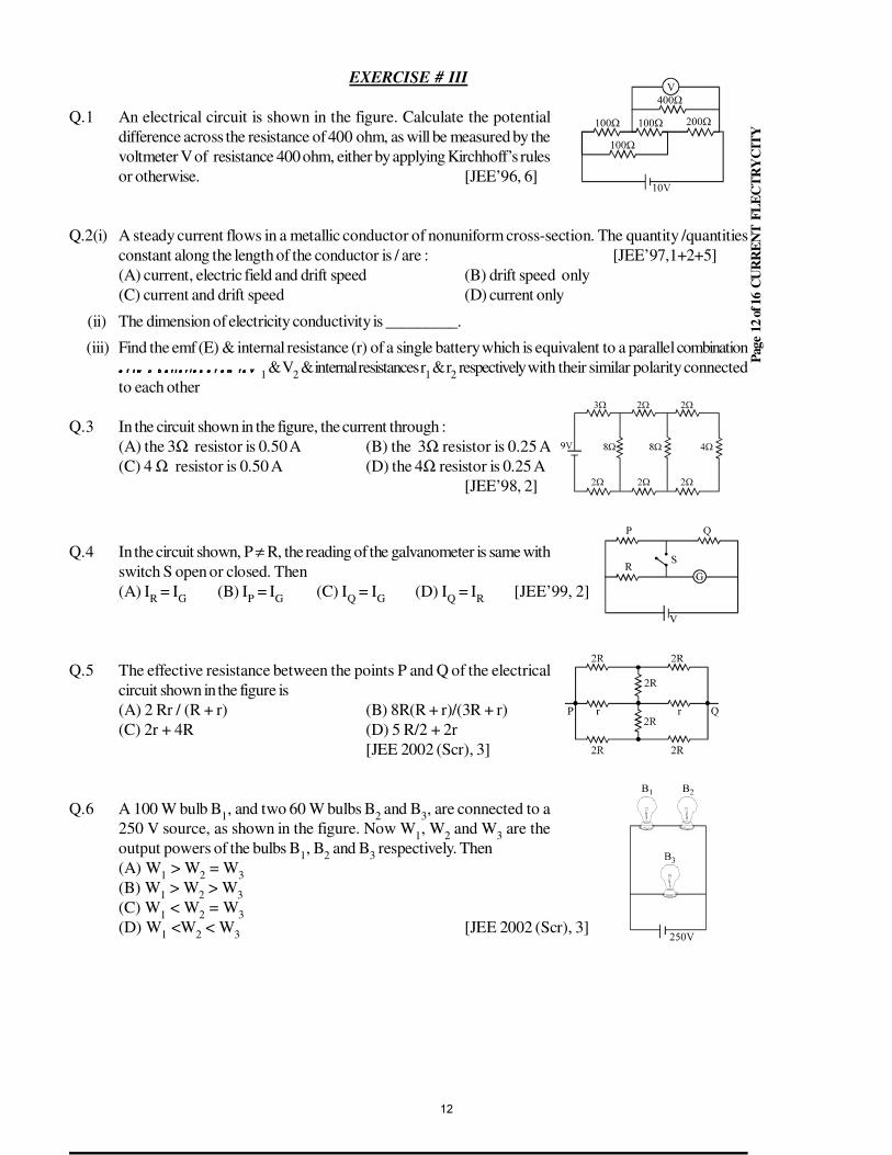
Pag
e 1
2 o
f 16
CU
RR
EN
T F
LE
CT
RY
CIT
Y
EXERCISE # III
Q.1 An electrical circuit is shown in the figure. Calculate the potential
difference across the resistance of 400 ohm, as will be measured by the
voltmeter V of resistance 400 ohm, either by applying Kirchhoff’s rules
or otherwise. [JEE’96, 6]
Q.2(i) A steady current flows in a metallic conductor of nonuniform cross-section. The quantity /quantities
constant along the length of the conductor is / are : [JEE’97,1+2+5]
(A) current, electric field and drift speed (B) drift speed only
(C) current and drift speed (D) current only
(ii) The dimension of electricity conductivity is _________.
(iii) Find the emf (E) & internal resistance (r) of a single battery which is equivalent to a parallel combination
o f t w o b a t t e r i e s o f e m f s Vo f t w o b a t t e r i e s o f e m f s Vo f t w o b a t t e r i e s o f e m f s Vo f t w o b a t t e r i e s o f e m f s V1 & V
2 & internal resistances r
1 & r
2 respectively with their similar polarity connected
to each other
Q.3 In the circuit shown in the figure, the current through :
(A) the 3Ω resistor is 0.50 A (B) the 3Ω resistor is 0.25 A
(C) 4 Ω resistor is 0.50 A (D) the 4Ω resistor is 0.25 A
[JEE’98, 2]
Q.4 In the circuit shown, P ≠ R, the reading of the galvanometer is same with
switch S open or closed. Then
(A) IR = I
G(B) I
P = I
G(C) I
Q = I
G(D) I
Q = I
R[JEE’99, 2]
Q.5 The effective resistance between the points P and Q of the electrical
circuit shown in the figure is
(A) 2 Rr / (R + r) (B) 8R(R + r)/(3R + r)
(C) 2r + 4R (D) 5 R/2 + 2r
[JEE 2002 (Scr), 3]
Q.6 A 100 W bulb B1, and two 60 W bulbs B
2 and B
3, are connected to a
250 V source, as shown in the figure. Now W1, W
2 and W
3 are the
output powers of the bulbs B1, B
2 and B
3 respectively. Then
(A) W1 > W
2 = W
3
(B) W1 > W
2 > W
3
(C) W1 < W
2 = W
3
(D) W1 <W
2 < W
3[JEE 2002 (Scr), 3]
12
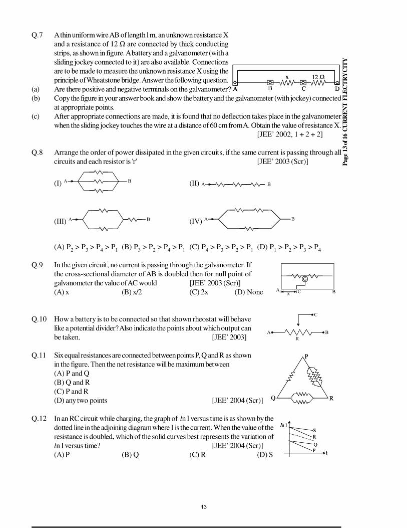
Pag
e 1
3 o
f 16
CU
RR
EN
T F
LE
CT
RY
CIT
Y
Q.7 A thin uniform wire AB of length l m, an unknown resistance X
and a resistance of 12 Ω are connected by thick conducting
strips, as shown in figure. A battery and a galvanometer (with a
sliding jockey connected to it) are also available. Connections
are to be made to measure the unknown resistance X using the
principle of Wheatstone bridge. Answer the following question.
(a) Are there positive and negative terminals on the galvanometer?
(b) Copy the figure in your answer book and show the battery and the galvanometer (with jockey) connected
at appropriate points.
(c) After appropriate connections are made, it is found that no deflection takes place in the galvanometer
when the sliding jockey touches the wire at a distance of 60 cm from A. Obtain the value of resistance X.
[JEE’ 2002, 1 + 2 + 2]
Q.8 Arrange the order of power dissipated in the given circuits, if the same current is passing through all
circuits and each resistor is 'r' [JEE’ 2003 (Scr)]
(I) (II)
(III) (IV)
(A) P2 > P
3 > P
4 > P
1(B) P
3 > P
2 > P
4 > P
1(C) P
4 > P
3 > P
2 > P
1(D) P
1 > P
2 > P
3 > P
4
Q.9 In the given circuit, no current is passing through the galvanometer. If
the cross-sectional diameter of AB is doubled then for null point of
galvanometer the value of AC would [JEE’ 2003 (Scr)]
(A) x (B) x/2 (C) 2x (D) None
Q.10 How a battery is to be connected so that shown rheostat will behave
like a potential divider? Also indicate the points about which output can
be taken. [JEE’ 2003]
Q.11 Six equal resistances are connected between points P, Q and R as shown
in the figure. Then the net resistance will be maximum between
(A) P and Q
(B) Q and R
(C) P and R
(D) any two points [JEE’ 2004 (Scr)]
Q.12 In an RC circuit while charging, the graph of ln I versus time is as shown by the
dotted line in the adjoining diagram where I is the current. When the value of the
resistance is doubled, which of the solid curves best represents the variation of
ln I versus time? [JEE’ 2004 (Scr)]
(A) P (B) Q (C) R (D) S
13
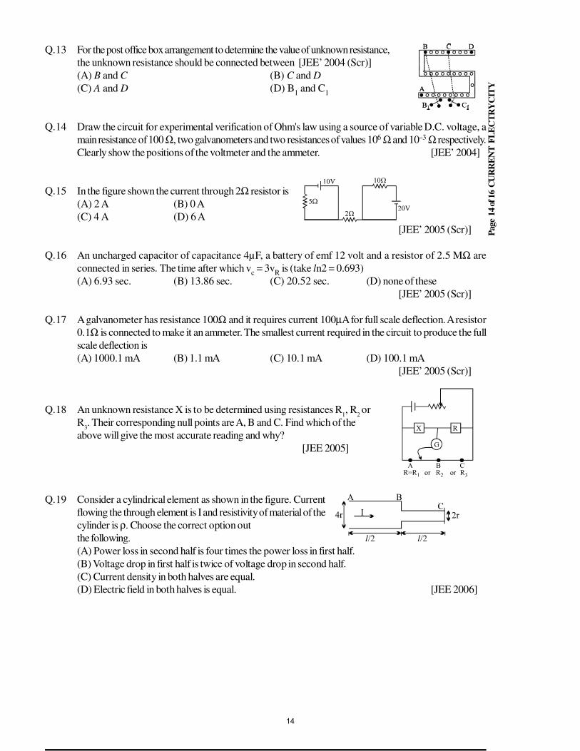
Pag
e 1
4 o
f 16
CU
RR
EN
T F
LE
CT
RY
CIT
Y
Q.13 For the post office box arrangement to determine the value of unknown resistance,
the unknown resistance should be connected between [JEE’ 2004 (Scr)]
(A) B and C (B) C and D
(C) A and D (D) B1 and C
1
Q.14 Draw the circuit for experimental verification of Ohm's law using a source of variable D.C. voltage, a
main resistance of 100 Ω, two galvanometers and two resistances of values 106 Ω and 10–3 Ω respectively.
Clearly show the positions of the voltmeter and the ammeter. [JEE’ 2004]
Q.15 In the figure shown the current through 2Ω resistor is
(A) 2 A (B) 0 A
(C) 4 A (D) 6 A
[JEE’ 2005 (Scr)]
Q.16 An uncharged capacitor of capacitance 4µF, a battery of emf 12 volt and a resistor of 2.5 MΩ are
connected in series. The time after which vc = 3v
R is (take ln2 = 0.693)
(A) 6.93 sec. (B) 13.86 sec. (C) 20.52 sec. (D) none of these
[JEE’ 2005 (Scr)]
Q.17 A galvanometer has resistance 100Ω and it requires current 100µA for full scale deflection. A resistor
0.1Ω is connected to make it an ammeter. The smallest current required in the circuit to produce the full
scale deflection is
(A) 1000.1 mA (B) 1.1 mA (C) 10.1 mA (D) 100.1 mA
[JEE’ 2005 (Scr)]
Q.18 An unknown resistance X is to be determined using resistances R1, R
2 or
R3. Their corresponding null points are A, B and C. Find which of the
above will give the most accurate reading and why?
[JEE 2005]
Q.19 Consider a cylindrical element as shown in the figure. Current
flowing the through element is I and resistivity of material of the
cylinder is ρ. Choose the correct option out
the following.
(A) Power loss in second half is four times the power loss in first half.
(B) Voltage drop in first half is twice of voltage drop in second half.
(C) Current density in both halves are equal.
(D) Electric field in both halves is equal. [JEE 2006]
14
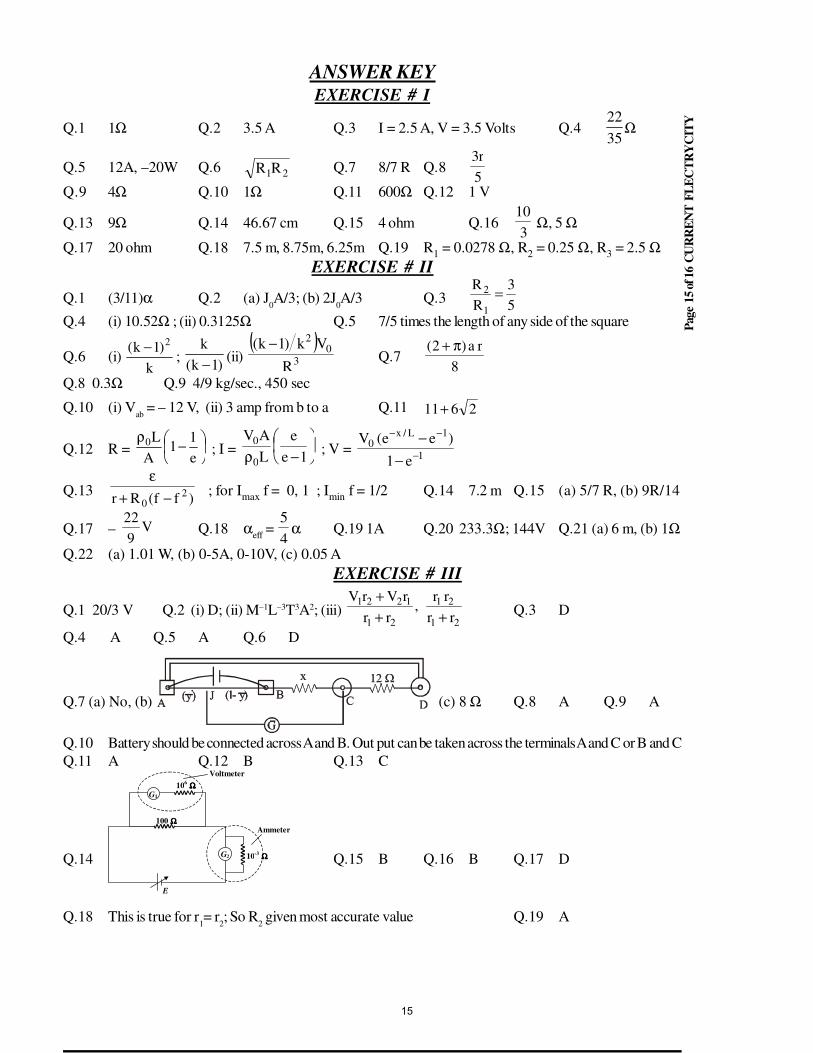
Pag
e 1
5 o
f 16
CU
RR
EN
T F
LE
CT
RY
CIT
Y
ANSWER KEYEXERCISE # I
Q.1 1Ω Q.2 3.5 A Q.3 I = 2.5 A, V = 3.5 Volts Q.422
35Ω
Q.5 12A, –20W Q.6 21RR Q.7 8/7 R Q.85
r3
Q.9 4Ω Q.10 1Ω Q.11 600Ω Q.12 1 V
Q.13 9Ω Q.14 46.67 cm Q.15 4 ohm Q.163
10 Ω, 5 Ω
Q.17 20 ohm Q.18 7.5 m, 8.75m, 6.25m Q.19 R1 = 0.0278 Ω, R
2 = 0.25 Ω, R
3 = 2.5 Ω
EXERCISE # II
Q.1 (3/11)α Q.2 (a) J0A/3; (b) 2J
0A/3 Q.3
5
3
R
R
1
2 =
Q.4 (i) 10.52Ω ; (ii) 0.3125Ω Q.5 7/5 times the length of any side of the square
Q.6 (i) k
)1k( 2−;
)1k(
k
− (ii) ( )
30
2
R
Vk)1k( −Q.7
8
ra)2( π+
Q.8 0.3Ω Q.9 4/9 kg/sec., 450 sec
Q.10 (i) Vab
= – 12 V, (ii) 3 amp from b to a Q.11 2611+
Q.12 R =
−ρ
e
11
A
L0 ; I =
−ρ 1e
e
L
AV
0
0 ; V =
1
1L/x0
e1
)ee(V−
−−
−
−
Q.13)ff(Rr 2
0 −+
ε; for I
max f = 0, 1 ; I
min f = 1/2 Q.14 7.2 m Q.15 (a) 5/7 R, (b) 9R/14
Q.17 – V9
22Q.18 α
eff =
4
5α Q.19 1A Q.20 233.3Ω; 144V Q.21 (a) 6 m, (b) 1Ω
Q.22 (a) 1.01 W, (b) 0-5A, 0-10V, (c) 0.05 A
EXERCISE # III
Q.1 20/3 V Q.2 (i) D; (ii) M–1L–3T3A2; (iii) 21
21
21
1221
rr
rr,
rr
rVrV
+++
Q.3 D
Q.4 A Q.5 A Q.6 D
Q.7 (a) No, (b) (c) 8 Ω Q.8 A Q.9 A
Q.10 Battery should be connected across A and B. Out put can be taken across the terminals A and C or B and C
Q.11 A Q.12 B Q.13 C
Q.14
Ammeter
10-3 ΩΩΩΩ
E
G2
G1
106 ΩΩΩΩ
Voltmeter
100 ΩΩΩΩ
Q.15 B Q.16 B Q.17 D
Q.18 This is true for r1= r
2; So R
2 given most accurate value Q.19 A
15
STUDY PACKAGE
Target: IIT-JEE (Advanced)
SUBJECT: PHYSICS
TOPIC: XII P4. Thermal and Chemical Effects of Electric Current
Index:
1. Key Concepts
2. Exercise I
3. Exercise II
4. Exercise III
5. Exercise IV
6. Answer Key
7. 34 Yrs. Que. from IIT-JEE
8. 10 Yrs. Que. from AIEEE
1
THERMAL AND CHEMICAL EFFECTS OF CURRENTQ.1 What are the SI units of electrical energy and electric power? What is the practical unit of electrical
energy?Sol. The S.I. unit of electrical energy is joule and that of electrical power is watt. The practical unit of electrical
energy is kilo watt-hour.Q.2 What is the cause of heating effect of current?Sol. When a potential difference is applied across a conductor, the free electrons are accelerated due to the
electric field. These electrons collide frequently with the ions in the conductor and lose their kinetic energy.which appears as heat energy.
Q.3 Write two characteristics of the wire of an electric heater.Sol. Two characteristics of a heater wire are:
(1) It should have high melting point.(2) It should have low resistance.
Q.4 What are the various factors on which the heat produced in a conductor depends?Sol. The various factors on which the heat produced in a conductor depends are
(a) the current through the conductor,(b) resistance of the conductor,(c) the time for which the currents is passed through the conductor.
Q.5 State Joule’s law of heating.Sol. Heat produced in a conductor of resistance R, when a current flows through it for time t, is given by
H = I2Rt. This is called Joule’s law.Q.6 Define S.I. unit of electrical power.Sol. S.I. unit of electric power is watt. The power consumed by an electric circuit is said to be one watt, if a
potential difference of one volt applied across it produces a current of one ampere in that circuit.
Q.7 Convert kWh into joules.Sol. I kWh =103W × 60 × 60s = 3.6 × 10⁶ J
Q.8 Of the two bulbs in a house, one glows brighter than the other. Which of the two has larger resistance?Sol. The resistance of the dimmer bulb is larger.
Q.9 What is an electrolyte?Sol. Substances which conduct electricity because a fraction of their molecules dissociate into positive and
negative ions are called electrolytes. The most common examples are acids, bases and salts which ionizewhen dissolved in water.
Q.10 What is electrolysis?Sol. The process of chemical decomposition of a conducting liquid (electrolyte) into its components when a
current is passed through it is called electrolysis.
Q.11 What are anions and cations?Sol. Anion: It is a negatively charged ion formed by addition of electrons to atoms or molecules. In electrolysis,
anions are attracted to the positive electrode (anode).Cation: It is a positively charged ion formed by removal of electrons from atoms or molecules. In electrolysis,cations are attracted to the negative electrode (cathode).
Q.12 State Faraday’s laws of electrolysis.Sol. Faraday’s First Law: The mass of a substance deposited or liberated at an electrode is proportional to the
quantity of charge that passes through the electrolyte, i.e.,m α Q
or m = ZQ = zItThe constant z is called the electrochemical equivalent (E.C.E.) of the substance.Faraday’s Second Law: If the same quantity of charge is passed through several electrolytes, then themasses of the various substances deposited at the respective electrodes are proportional to their chemicalequivalents (equivalent weights). Thus if m
1 and m
2 are the masses of two substances deposited and E
1
and E2 are their respective chemical equivalents, then
2
1
2
1
E
E
m
m= .
Q.13 Define electrochemical equivalent of an element.Sol. Electrochemical equivalent of an element is the mass of the element released from a solution of its ion
when a current of one ampere flows for one second during electrolysis.
2
Q.14 What is Faraday constant?Sol. Faraday constant is the quantity of charge required to liberate one equivalent weight of a substance. It is
equal to 96500 C.Q.15 Write some uses of electrolysis.Sol. Some of the important uses of electrolysis are:
(a) Electroplating (b) Purification of metals(c) Electrotyping (d) Medical applications etc.
Q.16 What is electroplating?Sol. Electroplating is the process in which a layer of some metal is deposited on any other surface by the
process of electrolysis. The anode is made of the metal to be deposited and the cathode is made of thesubstance which is to be electroplated.
Q.17 State two reasons, why electrolytes have lower electrical conductivity than metallic conductors in general.
Sol. (a) The ionic density in electrolytes is very small as compared to the free electron density in metals.(b) The mobility of free electrons in metal is much higher than the mobility of ions in electrolytes.
Q.18 What are strong electrolytes? Give examples.Sol. Those electrolytes which are completely ionised in their solutions are called strong electrolytes. For example
HCI, NaCI etc.
Q.19 What are weak electrolytes? Give examples.Sol. Some electrolytes are ionised to a small extent in their solutions. For example, NH
4Cl. Such electrolytes
are called weak electrolytes.
Q.20 If pure water is used, no electrolysis takes place. Why?Sol. Pure Water does not undergo electrolysis as it does not dissociate into constituent ions. Therefore water is
acidified before electrolysis.
Q.21 How does a voltmeter differ from a voltameter?Sol. Voltmeter is a device which is used to measure potential difference between two points, while voltameter
is a vessel containing an electrolyte with two electrodes immersed in it. Current can be measured withvoltameter.
Q.22 Write the SI unit of electrochemical equivalent.Sol. The SI unit of electrochemical equivalent (E.C.E.) is kg per coulomb.
Q.23 Name the electrodes on which hydrogen and oxygen are liberated during the electrolysis of water.Sol. During the electrolysis of water, hydrogen is liberated at the cathode and oxygen is liberated at the anode.
At the cathode the reaction is: 4H2O + 4e– → 4H– +2H2
At the anode the reaction is’: 2H2O → 4H+ + 4e– + O
2
Q.24 Why does molten sodium chloride conduct electricity? Explain.Sol. Sodium chloride in an ionic compound. Even in solid state it has Na+ and Cl– ions. When it is melted, ions
are free to move and became charge carriers. So NaCl in molten state conducts electricity.
Q.25 Is electrolysis possible with alternating current?Sol. No, electrolysis is not possible with a.c. For electrolysis current should pass continuously only in one
direction. In case current reverses its direction periodically, no deposition on the electrodes will take place.
Q.26 What is the difference between a fuse wire and a heater wire?Sol. The melting point of a fuse wire is very low while that of a heater wire is very high.
Q.27 What is an electrochemical cell ?Sol. An electrochemical cell is a system in which a chemical reaction produces an e.m.f. Thus a cell converts
chemical energy into electrical energy.
Q.28 Distinguish between primary and secondary cells.
Sol. A primary cell is one in which the chemical reaction that produces the emf is not reversible. Thus a primary
cell cannot be recharged. A secondary cell is one in which the chemical reaction is reversible. Thus a
secondary cell can be recharged.
Q.29 What is an accumulator or a storage cell? Write names of two storage cells.
Sol. A secondary cell is also called an accumulator or a storage cell. In these cells the chemical reaction is
reversible. So they can be recharged.
Two secondary cells are: (a) Lead-acid cell (b) Ni-Fe cell.
3
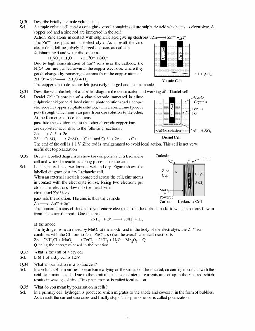
Q.30 Describe briefly a simple voltaic cell ?
Sol. A simple voltaic cell consists of a glass vessel containing dilute sulphuric acid which acts as electrolyte. A
copper rod and a zinc rod are immersed in the acid.
Action: Zinc atoms in contact with sulphuric acid give up electrons : Zn → Zn++ + 2e–
The Zn++ ions pass into the electrolyte. As a result the zinc
electrode is left negatively charged and acts as cathode.
Sulphuric acid and water dissociate as
H2SO
4 + H
2O → 2H3O+ + SO
4–
Due to high concentration of Zn++ ions near the cathode, the
H3O+ ions are pushed towards the copper electrode, where they
get discharged by removing electrons from the copper atoms:-
2H3O+ + 2e– → 2H
2O + H
2
The copper electrode is thus left positively charged and acts as anode.
Q.31 Describe with the help of a labelled diagram the construction and working of a Daniel cell.
Sol. Deniel Cell: It consists of a zinc electrode immersed in dilute
sulphuric acid (or acidulated zinc sulphate solution) and a copper
electrode in copper sulphate solution, with a membrane (porous
pot) through which ions can pass from one solution to the other.
At the former electrode zinc ions
pass into the solution and at the other electrode copper ions
are deposited, according to the following reactions :
Zn → Zn++ + 2e–
Z++ + CuSO4 → ZnSO
4 + Cu++ and Cu++ + 2e– → Cu
The emf of the cell is 1.1 V. Zinc rod is amalgamated to avoid local action. This cell is not very
useful due to polarization.
Q.32 Draw a labelled diagram to show the components of a Leclanche
cell and write the reactions taking place inside the cell.
Sol. Laclanche cell has two forms - wet and dry. Figure shows the
labelled diagram of a dry Laclanche cell.
When an external circuit is connected across the cell, zinc atoms
in contact with the electrolyte ionize, losing two electrons per
atom. The electrons flow into the metal wire
circuit and Zn++ ions
pass into the solution. The zinc is thus the cathode:
Zn → Zn++ + 2e–
The ammonium ions of the electrolyte remove electrons from the carbon anode, to which electrons flow in
from the external circuit. One thus has
2NH4+ + 2e– → 2NH
3 + H
2
at the anode.
The hydrogen is neutralized by MnO2 at the anode, and in the body of the electrolyte, the Zn++ ion
combines with the Cl– ions to form ZnCl2, so that the overall chemical reaction is
Zn + 2NH4Cl + MnO
2 → ZnCl
2 + 2NH
3 + H
2O + Mn
2O
3 + Q
Q being the energy released in the reaction.
Q.33 What is the emf of a dry cell.
Sol. E.M.F.of a dry cell is 1.5V.
Q.34 What is local action in a voltaic cell?
Sol. In a voltaic cell, impurities like carbon etc. lying on the surface of the zinc rod, on coming in contact with the
acid form minute cells. Due to these minute cells some internal currents are set up in the zinc rod which
results in wastage of zinc. This phenomenon is called local action.
Q.35 What do you mean by polarisation in cells?
Sol. In a primary cell, hydrogen is produced which migrates to the anode and covers it in the form of bubbles.
As a result the current decreases and finally stops. This phenomenon is called polarization.
4
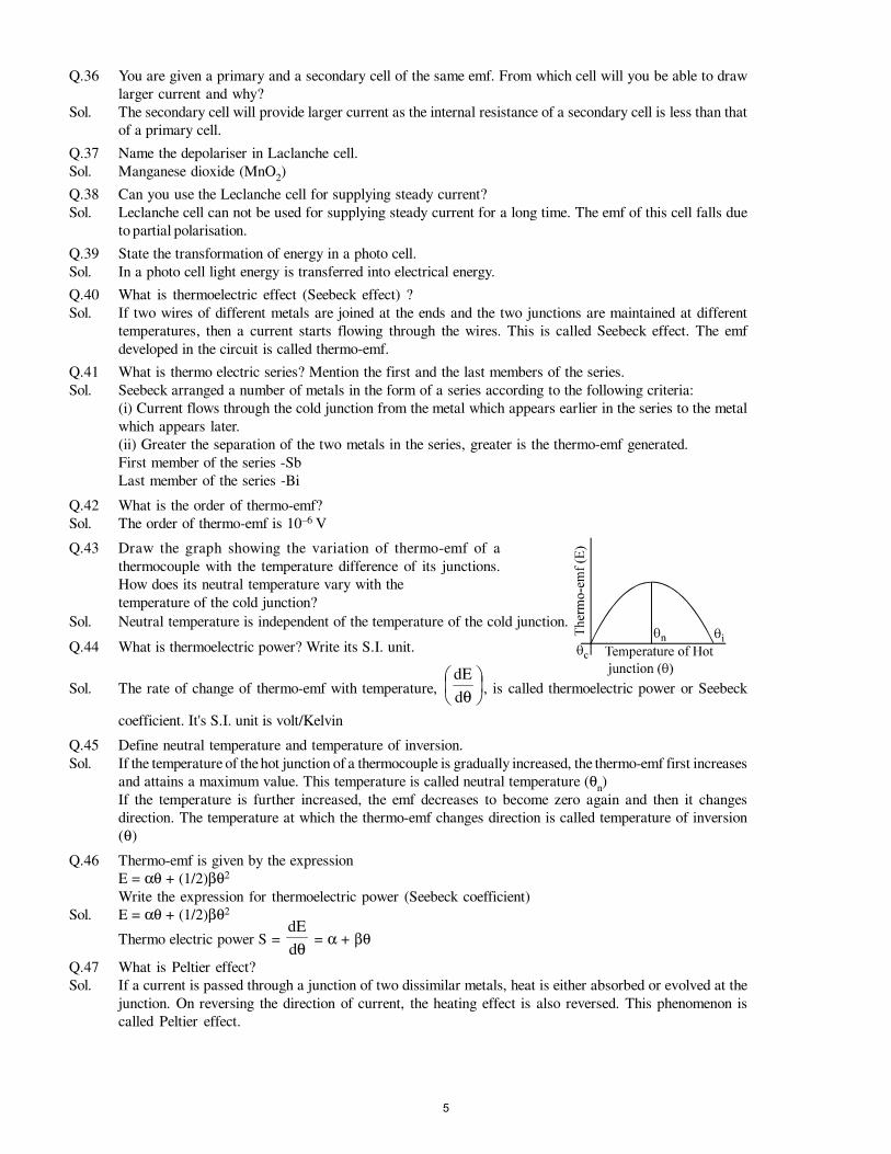
Q.36 You are given a primary and a secondary cell of the same emf. From which cell will you be able to draw
larger current and why?
Sol. The secondary cell will provide larger current as the internal resistance of a secondary cell is less than that
of a primary cell.
Q.37 Name the depolariser in Laclanche cell.
Sol. Manganese dioxide (MnO2)
Q.38 Can you use the Leclanche cell for supplying steady current?
Sol. Leclanche cell can not be used for supplying steady current for a long time. The emf of this cell falls due
to partial polarisation.
Q.39 State the transformation of energy in a photo cell.
Sol. In a photo cell light energy is transferred into electrical energy.
Q.40 What is thermoelectric effect (Seebeck effect) ?
Sol. If two wires of different metals are joined at the ends and the two junctions are maintained at different
temperatures, then a current starts flowing through the wires. This is called Seebeck effect. The emf
developed in the circuit is called thermo-emf.
Q.41 What is thermo electric series? Mention the first and the last members of the series.
Sol. Seebeck arranged a number of metals in the form of a series according to the following criteria:
(i) Current flows through the cold junction from the metal which appears earlier in the series to the metal
which appears later.
(ii) Greater the separation of the two metals in the series, greater is the thermo-emf generated.
First member of the series -Sb
Last member of the series -Bi
Q.42 What is the order of thermo-emf?
Sol. The order of thermo-emf is 10–6 V
Q.43 Draw the graph showing the variation of thermo-emf of a
thermocouple with the temperature difference of its junctions.
How does its neutral temperature vary with the
temperature of the cold junction?
Sol. Neutral temperature is independent of the temperature of the cold junction.
Q.44 What is thermoelectric power? Write its S.I. unit.
Sol. The rate of change of thermo-emf with temperature,
θd
dE, is called thermoelectric power or Seebeck
coefficient. It's S.I. unit is volt/Kelvin
Q.45 Define neutral temperature and temperature of inversion.
Sol. If the temperature of the hot junction of a thermocouple is gradually increased, the thermo-emf first increases
and attains a maximum value. This temperature is called neutral temperature (θn)
If the temperature is further increased, the emf decreases to become zero again and then it changes
direction. The temperature at which the thermo-emf changes direction is called temperature of inversion
(θ)
Q.46 Thermo-emf is given by the expression
E = αθ + (1/2)βθ2
Write the expression for thermoelectric power (Seebeck coefficient)
Sol. E = αθ + (1/2)βθ2
Thermo electric power S = θd
dE = α + βθ
Q.47 What is Peltier effect?
Sol. If a current is passed through a junction of two dissimilar metals, heat is either absorbed or evolved at the
junction. On reversing the direction of current, the heating effect is also reversed. This phenomenon is
called Peltier effect.
5
Q.48 Define Peltier coefficient.
Sol. Peltier coefficient is defined as the amount of heat absorbed or evolved per second at a junction when a
current of I A is passed through it.
Q.49 What is Thomson effect?
Sol. The production of an electric potential gradient along a conductor as a result of a temperature gradient
along it is called Thomson effect. Thus points at different temperatures in a conductor are at different
potentials.
Q.50 What is a Thermopile?
Sol. Thermopile is a series combination of thermocouples. It is used to detect and measure the intensity of heat
radiation.
Q.51 Mention some applications of thermoelectric effect.
Sol. Some of the important applications of thermoelectric effect are:
(a) Power generation (b) Measurement of temperature (c) Remgeration.
Q.52 Name the carriers of current in the following voltameters:
(a) Copper electrodes in CuSO4
solution.
(b) Platinum electrodes in dilute sulphuric acid.
Sol. (a) Cu++ and SO– – ions. (b) H+ and OH– ions.
Q.53 Write the expression which gives the relation of the thermoelectric emf of a thermocouple with the
temperature difference of its cold and hot junctions.
Sol. E = αθ + (1/2)βθ2 where a and β are constants.
Q.54 Give one practical application of thermoelectricity.
Sol. Measurement of temperature.
Q.55 Why is an electrolyte dissociated when dissolved in liquids ?
Sol. The ionic bonds between the ions of the solute are made weak by polar molecules of liquids. Therefore the ions of electrolyte (solute) get dissociated.
Q.56 How is the electrical conductivity of an electrolyte affected by increase of temperature?
Sol. The electrical conductivity of an electrolyte increases with the increase in temperature.
Q.57 Write one main difference between primary and secondary cells.
Sol. The primary cells can not be recharged while in secondary cells reversible reactions take place so that they can be recharged.
Q.58 What is the direction of the thermoelectric current at the hot junction of an iron-copper thermocouple?
Sol. From copper to iron.
Q.59 What is the relation between temperature of cold junction, neutral temperature and inversion temperature?
Sol.2
cin
θ+θ=θ
where θn is neutral temperature, θ
c is temperature of cold junction, and θ
i is inversion temperature.
Q.60 Name the thermocouple which is used to measure a temperature of 300 K.
Sol. Copper-Constatantan thermocouple.
Q.61 How are metals purified by electrolysis process?
Sol. For purification of metals by electrolysis, anode is made of the impure metal and cathode of pure metal.
The electrolyte used is any soluble salt of pure metal. When current is passed through the electrolyte, pure
metal gets deposited on the cathode.
Q.62 Describe briefly a lead-acid accumulator, giving its charging and discharging chemical equations.
Sol. Lead-acid accumulator is a secondary cell which can be recharged by passing a current through it in the
reverse direction. The chemical process that occurred at the electrodes are then reversed and the cell recovers
its original state.
The electrodes consist of alternating parallel plates of lead dioxide (positive electrode) and spongy lead (negative
electrode) insulated from each other. They are immersed in an electrolyte of dilute sulphuric acid.
Reactions: H2SO
4 dissociates into H+ and SO– – ions.
During discharging:
At Cathode: Pb + SO4– – → PbSO
4 + 2e–
At anode: PbO2 + 2H+ + 2e– → PbO + H
2O
PbO + H2SO
4 → PbSO
4 + H
2O
6
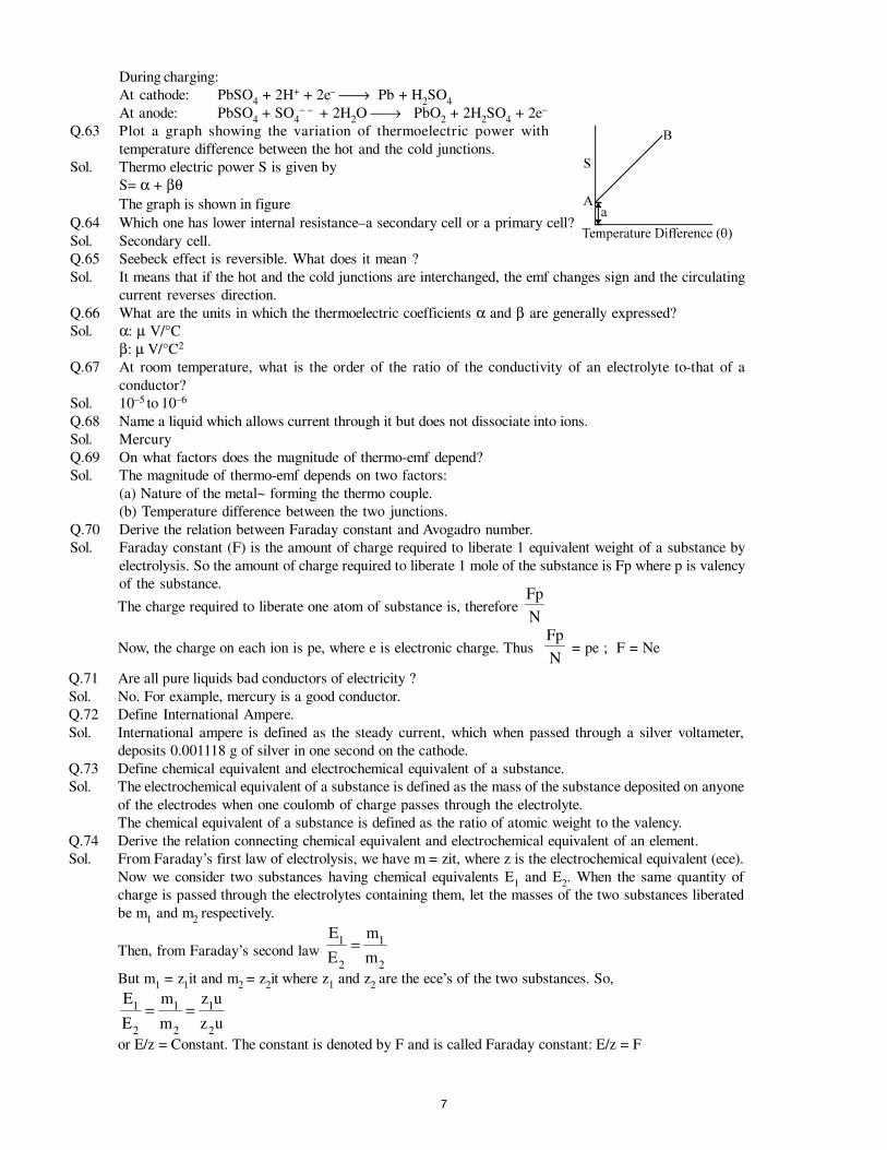
During charging:
At cathode: PbSO4 + 2H+ + 2e– → Pb + H
2SO
4
At anode: PbSO4 + SO
4– – + 2H
2O → PbO
2 + 2H
2SO
4 + 2e–
Q.63 Plot a graph showing the variation of thermoelectric power with
temperature difference between the hot and the cold junctions.
Sol. Thermo electric power S is given by
S= α + βθThe graph is shown in figure
Q.64 Which one has lower internal resistance–a secondary cell or a primary cell?
Sol. Secondary cell.
Q.65 Seebeck effect is reversible. What does it mean ?
Sol. It means that if the hot and the cold junctions are interchanged, the emf changes sign and the circulating
current reverses direction.
Q.66 What are the units in which the thermoelectric coefficients α and β are generally expressed?
Sol. α: µ V/°C
β: µ V/°C2
Q.67 At room temperature, what is the order of the ratio of the conductivity of an electrolyte to-that of a
conductor?
Sol. 10–5 to 10–6
Q.68 Name a liquid which allows current through it but does not dissociate into ions.
Sol. Mercury
Q.69 On what factors does the magnitude of thermo-emf depend?
Sol. The magnitude of thermo-emf depends on two factors:
(a) Nature of the metal~ forming the thermo couple.
(b) Temperature difference between the two junctions.
Q.70 Derive the relation between Faraday constant and Avogadro number.
Sol. Faraday constant (F) is the amount of charge required to liberate 1 equivalent weight of a substance by
electrolysis. So the amount of charge required to liberate 1 mole of the substance is Fp where p is valency
of the substance.
The charge required to liberate one atom of substance is, therefore N
Fp
Now, the charge on each ion is pe, where e is electronic charge. Thus N
Fp = pe ; F = Ne
Q.71 Are all pure liquids bad conductors of electricity ?
Sol. No. For example, mercury is a good conductor.
Q.72 Define International Ampere.
Sol. International ampere is defined as the steady current, which when passed through a silver voltameter,
deposits 0.001118 g of silver in one second on the cathode.
Q.73 Define chemical equivalent and electrochemical equivalent of a substance.
Sol. The electrochemical equivalent of a substance is defined as the mass of the substance deposited on anyone
of the electrodes when one coulomb of charge passes through the electrolyte.
The chemical equivalent of a substance is defined as the ratio of atomic weight to the valency.
Q.74 Derive the relation connecting chemical equivalent and electrochemical equivalent of an element.
Sol. From Faraday’s first law of electrolysis, we have m = zit, where z is the electrochemical equivalent (ece).
Now we consider two substances having chemical equivalents E1 and E
2. When the same quantity of
charge is passed through the electrolytes containing them, let the masses of the two substances liberated
be m1 and m
2 respectively.
Then, from Faraday’s second law 2
1
2
1
m
m
E
E=
But m1 = z
1it and m
2 = z
2it where z
1 and z
2 are the ece’s of the two substances. So,
uz
uz
m
m
E
E
2
1
2
1
2
1 ==
or E/z = Constant. The constant is denoted by F and is called Faraday constant: E/z = F
7
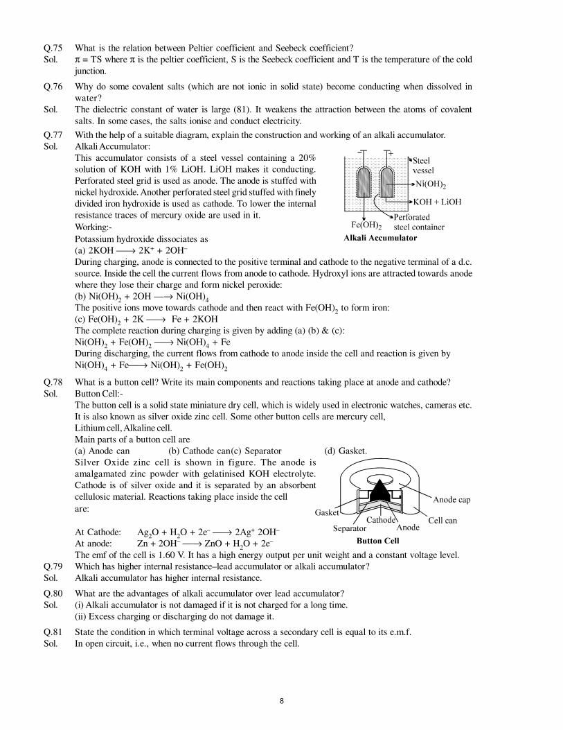
Q.75 What is the relation between Peltier coefficient and Seebeck coefficient?
Sol. π = TS where π is the peltier coefficient, S is the Seebeck coefficient and T is the temperature of the cold
junction.
Q.76 Why do some covalent salts (which are not ionic in solid state) become conducting when dissolved in
water?
Sol. The dielectric constant of water is large (81). It weakens the attraction between the atoms of covalent
salts. In some cases, the salts ionise and conduct electricity.
Q.77 With the help of a suitable diagram, explain the construction and working of an alkali accumulator.
Sol. Alkali Accumulator:
This accumulator consists of a steel vessel containing a 20%
solution of KOH with 1% LiOH. LiOH makes it conducting.
Perforated steel grid is used as anode. The anode is stuffed with
nickel hydroxide. Another perforated steel grid stuffed with finely
divided iron hydroxide is used as cathode. To lower the internal
resistance traces of mercury oxide are used in it.
Working:-
Potassium hydroxide dissociates as
(a) 2KOH → 2K+ + 2OH–
During charging, anode is connected to the positive terminal and cathode to the negative terminal of a d.c.
source. Inside the cell the current flows from anode to cathode. Hydroxyl ions are attracted towards anode
where they lose their charge and form nickel peroxide:
(b) Ni(OH)2 + 2OH —→ Ni(OH)
4
The positive ions move towards cathode and then react with Fe(OH)2 to form iron:
(c) Fe(OH)2 + 2K → Fe + 2KOH
The complete reaction during charging is given by adding (a) (b) & (c):
Ni(OH)2 + Fe(OH)
2 → Ni(OH)
4 + Fe
During discharging, the current flows from cathode to anode inside the cell and reaction is given by
Ni(OH)4 + Fe→ Ni(OH)
2 + Fe(OH)
2
Q.78 What is a button cell? Write its main components and reactions taking place at anode and cathode?
Sol. Button Cell:-
The button cell is a solid state miniature dry cell, which is widely used in electronic watches, cameras etc.
It is also known as silver oxide zinc cell. Some other button cells are mercury cell,
Lithium cell, Alkaline cell.
Main parts of a button cell are
(a) Anode can (b) Cathode can(c) Separator (d) Gasket.
Silver Oxide zinc cell is shown in figure. The anode is
amalgamated zinc powder with gelatinised KOH electrolyte.
Cathode is of silver oxide and it is separated by an absorbent
cellulosic material. Reactions taking place inside the cell
are:
At Cathode: Ag2O + H
2O + 2e– → 2Ag+ 2OH–
At anode: Zn + 2OH– → ZnO + H2O + 2e–
The emf of the cell is 1.60 V. It has a high energy output per unit weight and a constant voltage level.
Q.79 Which has higher internal resistance–lead accumulator or alkali accumulator?
Sol. Alkali accumulator has higher internal resistance.
Q.80 What are the advantages of alkali accumulator over lead accumulator?
Sol. (i) Alkali accumulator is not damaged if it is not charged for a long time.
(ii) Excess charging or discharging do not damage it.
Q.81 State the condition in which terminal voltage across a secondary cell is equal to its e.m.f.
Sol. In open circuit, i.e., when no current flows through the cell.
8
MAGNETIC PROPERTIES OF MATTER
Summary with Applications
Atomic currents, magnetic dipoles, and magnetization
In a simple model, an orbiting electron has a magnetic moment proportional to its orbital angular momentum,
m = –e
me
2L ...............(1)
and a singular contribution due to the spin angular momentum,
m = e
me
S ..............(2)
The magnetization in a material is the magnetic moment per unit volume:
M = < ∑ >m
V
i
∆.............(3)
Diamagnetism
In diamagnetism materials, magnetic dipole moments are induced in molecules by the magnetic field, and
the vectors M and B have opposite directions.
Paramagnetism
The permanent magnetic moment of an unpaired electron in a paramagnetic substance tends to become
aligned with the magnetic field. The vectors M and B are parallel and are related by Curie’s law
M = CB
Tµ0
...............(4)
valid except at low temperatures and high fields.
Ferromagnetism
Molecular magnetic dipoles in a magnetic domain tend to be aligned in a ferromagnetic material. If the
domains are oriented preferentially by applying a magnetic field, the sample has a large magnetization. The
magnetization can persist in hard magnetic materials to form a permanent magnet.
Magnetic intensity H
The magnetic intensity H is defined by the relation
B = µ0 (H + M) ................(5)
For a linear medium with permeability µ, the relation can be expressed as B = µH. For a Rowland ring, H
is due to the macroscopic current in the windings. The relation between B and H for ferromagnetic materials
is nonlinear, and hysteresis effects are present.
The magnetic field of the earth
Outside its surface, the earth’s magnetic field is approximately a dipole field. Large changes in the field
occur over geological time intervals.
9
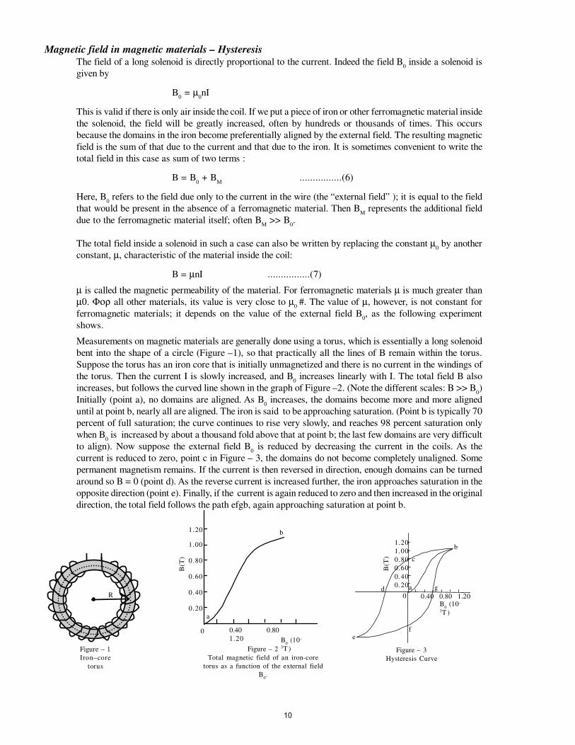
Magnetic field in magnetic materials – Hysteresis
The field of a long solenoid is directly proportional to the current. Indeed the field B0 inside a solenoid is
given by
B0 = µ
0nI
This is valid if there is only air inside the coil. If we put a piece of iron or other ferromagnetic material inside
the solenoid, the field will be greatly increased, often by hundreds or thousands of times. This occurs
because the domains in the iron become preferentially aligned by the external field. The resulting magnetic
field is the sum of that due to the current and that due to the iron. It is sometimes convenient to write the
total field in this case as sum of two terms :
B = B0 + B
M................(6)
Here, B0 refers to the field due only to the current in the wire (the “external field” ); it is equal to the field
that would be present in the absence of a ferromagnetic material. Then BM
represents the additional field
due to the ferromagnetic material itself; often BM
>> B0.
The total field inside a solenoid in such a case can also be written by replacing the constant µ0 by another
constant, µ, characteristic of the material inside the coil:
B = µnI ................(7)
µ is called the magnetic permeability of the material. For ferromagnetic materials µ is much greater than
µ0. Φορ all other materials, its value is very close to µ0
#. The value of µ, however, is not constant for
ferromagnetic materials; it depends on the value of the external field B0, as the following experiment
shows.
Measurements on magnetic materials are generally done using a torus, which is essentially a long solenoid
bent into the shape of a circle (Figure –1), so that practically all the lines of B remain within the torus.
Suppose the torus has an iron core that is initially unmagnetized and there is no current in the windings of
the torus. Then the current I is slowly increased, and B0 increases linearly with I. The total field B also
increases, but follows the curved line shown in the graph of Figure –2. (Note the different scales: B >> B0)
Initially (point a), no domains are aligned. As B0 increases, the domains become more and more aligned
until at point b, nearly all are aligned. The iron is said to be approaching saturation. (Point b is typically 70
percent of full saturation; the curve continues to rise very slowly, and reaches 98 percent saturation only
when B0 is increased by about a thousand fold above that at point b; the last few domains are very difficult
to align). Now suppose the external field B0 is reduced by decreasing the current in the coils. As the
current is reduced to zero, point c in Figure – 3, the domains do not become completely unaligned. Some
permanent magnetism remains. If the current is then reversed in direction, enough domains can be turned
around so B = 0 (point d). As the reverse current is increased further, the iron approaches saturation in the
opposite direction (point e). Finally, if the current is again reduced to zero and then increased in the original
direction, the total field follows the path efgb, again approaching saturation at point b.
R
Figure – 1
Iron–core
torus
a
b
0.40 0.80
1.20 B0 (10–
3T )
0
1.20
1.00
0.80
0.60
0.40
0.20
B(T
)
Figure – 2
Total magnetic field of an iron-core
torus as a function of the external field
B0.
a
b
0.40 0.80 1.20B
0 (10–
3T )
0
1.20
1.00
0.80
0.60
0.40
0.20
B(T
)
Figure – 3
Hysteresis Curve
c
f
d g
e
10
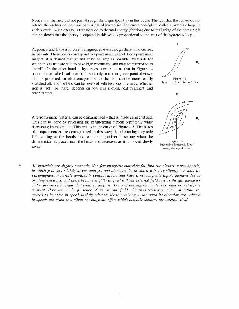
Notice that the field did not pass through the origin (point a) in this cycle. The fact that the curves do not
retrace themselves on the same path is called hysteresis. The curve bcdefgb is called a hyteresis loop. In
such a cycle, much energy is transformed to thermal energy (friction) due to realigning of the domains; it
can be shown that the energy dissipated in this way is proportional to the area of the hysteresis loop.
At point c and f, the iron core is magnetized even though there is no current
in the coils. These points correspond to a permanent magnet. For a permanent
magnet, it is desired that ac and af be as large as possible. Materials for
which this is true are said to have high retentivity, and may be referred to as
“hard”. On the other hand, a hysteresis curve such as that in Figure –4
occurs for so-called “soft iron” (it is soft only from a magnetic point of view).
This is preferred for electromagnets since the field can be more readily
switched off, and the field can be reversed with less loss of energy. Whether
iron is “soft” or “hard” depends on how it is alloyed, heat treatment, and
other factors.
A ferromagnetic material can be demagnetized – that is, made unmagnetized.
This can be done by reversing the magnetizing current repeatedly while
decreasing its magnitude. This results in the curve of Figure – 5. The heads
of a tape recorder are demagnetized in this way; the alternating magnetic
field acting at the heads due to a demagnetizer is strong when the
demagnetizer is placed near the heads and decreases as it is moved slowly
away.
# All materials are slightly magnetic. Non-ferromagnetic materials fall into two classes: paramagnetic,
in which µ is very slightly larger than µ0; and diamagnetic, in which µ is very slightly less than µ
0.
Paramagnetic materials apparently contain atoms that have a net magnetic dipole moment due to
orbiting electrons, and these become slightly aligned with an external field just as the galvanometer
coil experiences a torque that tends to align it. Atoms of diamagnetic materials have no net dipole
moment. However, in the presence of an external field, electrons revolving in one direction are
caused to increase in speed slightly, whereas those revolving in the opposite direction are reduced
in speed; the result is a slight net magnetic effect which actually opposes the external field.
B0
B
Figure – 4
Hysteresis Curve for soft iron
B0
B
Figure – 5
Successive hysteresis loops
during demagnetization
11
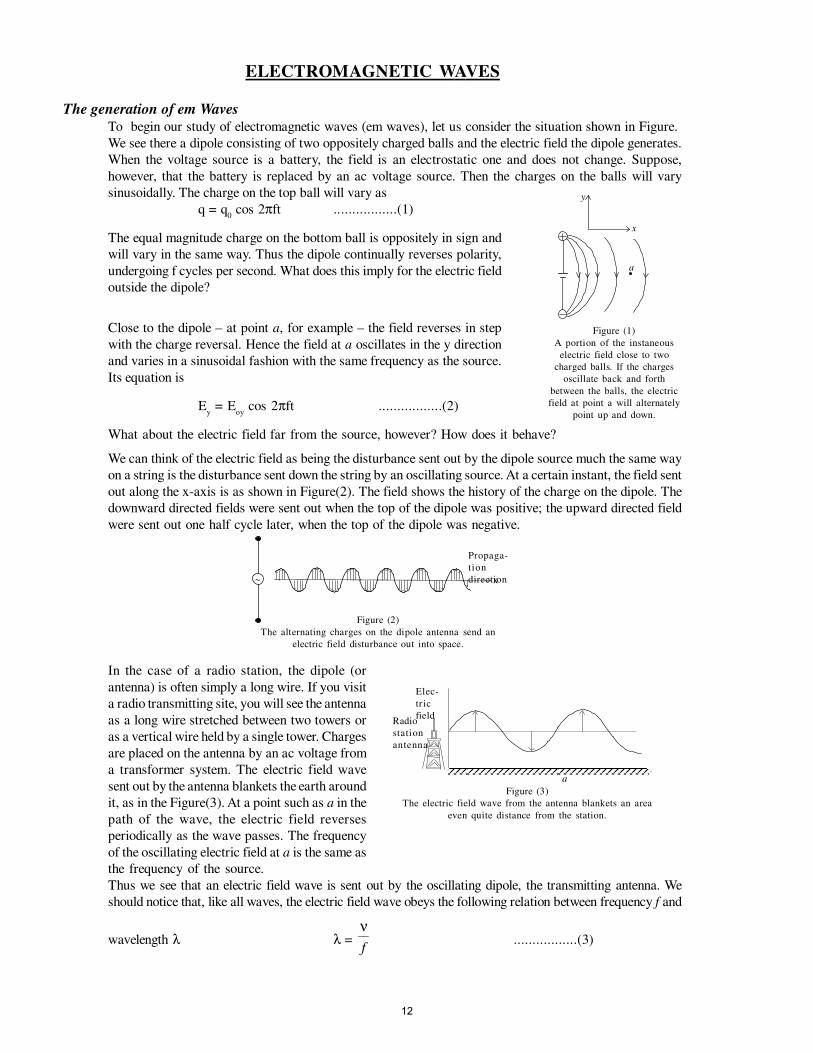
ELECTROMAGNETIC WAVES
The generation of em Waves
To begin our study of electromagnetic waves (em waves), let us consider the situation shown in Figure.
We see there a dipole consisting of two oppositely charged balls and the electric field the dipole generates.
When the voltage source is a battery, the field is an electrostatic one and does not change. Suppose,
however, that the battery is replaced by an ac voltage source. Then the charges on the balls will vary
sinusoidally. The charge on the top ball will vary as
q = q0 cos 2πft .................(1)
The equal magnitude charge on the bottom ball is oppositely in sign and
will vary in the same way. Thus the dipole continually reverses polarity,
undergoing f cycles per second. What does this imply for the electric field
outside the dipole?
Close to the dipole – at point a, for example – the field reverses in step
with the charge reversal. Hence the field at a oscillates in the y direction
and varies in a sinusoidal fashion with the same frequency as the source.
Its equation is
Ey = E
oy cos 2πft .................(2)
What about the electric field far from the source, however? How does it behave?
We can think of the electric field as being the disturbance sent out by the dipole source much the same way
on a string is the disturbance sent down the string by an oscillating source. At a certain instant, the field sent
out along the x-axis is as shown in Figure(2). The field shows the history of the charge on the dipole. The
downward directed fields were sent out when the top of the dipole was positive; the upward directed field
were sent out one half cycle later, when the top of the dipole was negative.
In the case of a radio station, the dipole (or
antenna) is often simply a long wire. If you visit
a radio transmitting site, you will see the antenna
as a long wire stretched between two towers or
as a vertical wire held by a single tower. Charges
are placed on the antenna by an ac voltage from
a transformer system. The electric field wave
sent out by the antenna blankets the earth around
it, as in the Figure(3). At a point such as a in the
path of the wave, the electric field reverses
periodically as the wave passes. The frequency
of the oscillating electric field at a is the same as
the frequency of the source.
Thus we see that an electric field wave is sent out by the oscillating dipole, the transmitting antenna. We
should notice that, like all waves, the electric field wave obeys the following relation between frequency f and
wavelength λ λ = νf
.................(3)
y
x
a
Figure (1)
A portion of the instaneous
electric field close to two
charged balls. If the charges
oscillate back and forth
between the balls, the electric
field at point a will alternately
point up and down.
~
Propaga-
tion
directionx
Figure (2)
The alternating charges on the dipole antenna send an
electric field disturbance out into space.
Elec-
tr ic
fieldRadio
station
antenna
a
Figure (3)
The electric field wave from the antenna blankets an area
even quite distance from the station.
12
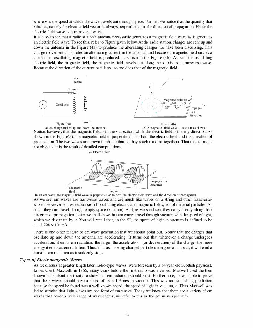
where ν is the speed at which the wave travels out through space. Further, we notice that the quantity that
vibrates, namely the electric field vector, is always perpendicular to the direction of propagation. Hence the
electric field wave is a transverse wave .
It is easy to see that a radio station’s antenna necessarily generates a magnetic field wave as it generates
an electric field wave. To see this, refer to Figure given below. At the radio station, charges are sent up and
down the antenna in the Figure (4a) to produce the alternating charges we have been discussing. This
charge movement constitutes an alternating current in the antenna, and because a magnetic field circles a
current, an oscillating magnetic field is produced, as shown in the Figure (4b). As with the oscillating
electric field, the magnetic field, the magnetic field travels out along the x-axis as a transverse wave.
Because the direction of the current oscillates, so too does that of the magnetic field.
Notice, however, that the magnetic field is in the z direction, while the electric field is in the y-direction. As
shown in the Figure(5), the magnetic field id perpendicular to both the electric field and the direction of
propagation. The two waves are drawn in phase (that is, they reach maxima together). That this is true is
not obvious; it is the result of detailed computations.
As we see, em waves are transverse waves and are much like waves on a string and other transverse-
waves. However, em waves consist of oscillating electric and magnetic fields, not of material particles. As
such, they can travel through empty space (vacuum). And, as we shall see, they carry energy along their
direction of propagation. Later we shall show that em waves travel through vacuum with the speed of light,
which we designate by c. You will recall that, in the SI, the speed of light in vacuum is defined to be
c = 2.998 × 10⁸ m/s.
There is one other feature of em wave generation that we should point out. Notice that the charges that
oscillate up and down the antenna are accelerating. It turns out that whenever a charge undergoes
acceleration, it emits em radiation; the larger the acceleration (or deceleration) of the charge, the more
energy it emits as em radiation. Thus, if a fast-moving charged particle undergoes an impact, it will emit a
burst of em radiation as it suddenly stops.
Types of Electromagnetic Waves
As we discuss at greater length later, radio-type waves were foreseen by a 34 year old Scottish physicist,
James Clerk Maxwell, in 1865, many years before the first radio was invented. Maxwell used the then
known facts about electricity to show that em radiation should exist. Furthermore, he was able to prove
that these waves should have a speed of 3 × 10⁸ m/s in vacuum. This was an astonishing prediction
because the speed he found was a well known speed, the speed of light in vacuum, c. Thus Maxwell was
led to surmise that light waves are one form of em waves. Today we know that there are a variety of em
waves that cover a wide range of wavelengths; we refer to this as the em wave spectrum.
y
x
zI
Magnetic field wave
Propaga-
t ion
direction
x
Figure (4b)
~
An-
tenna
Trans-
former
Oscillator
Figure (4a)
(a) As charge rushes up and down the antenna. (b) A magnetic field wave is sent out as shown.
Electric fieldy
x
z Magnetic
field
Propagation
direction
Figure (5)
In an em wave, the magnetic field wave is perpendicular to both the electric field wave and the direction of propagation.
13
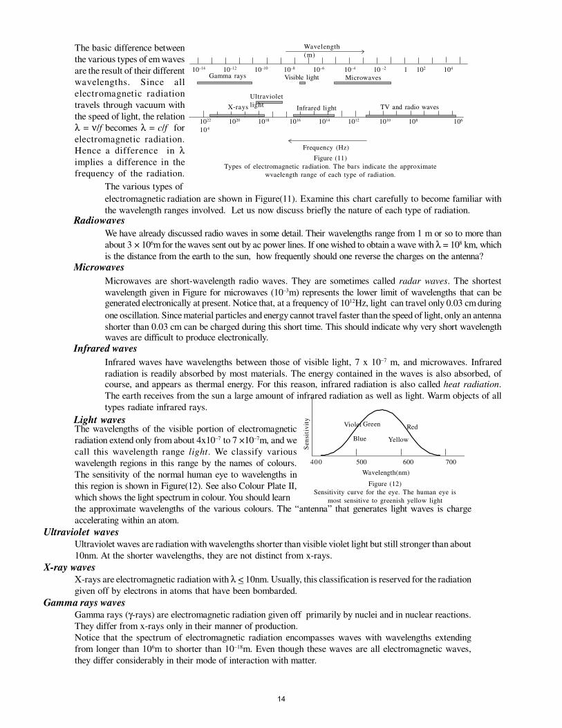
The basic difference between
the various types of em waves
are the result of their different
wavelengths. Since all
electromagnetic radiation
travels through vacuum with
the speed of light, the relation
λ = ν/f becomes λ = c/f for
electromagnetic radiation.
Hence a difference in λimplies a difference in the
frequency of the radiation.
The wavelengths of the visible portion of electromagnetic
radiation extend only from about 4x10⁻⁷ to 7 ×10⁻⁷m, and we
call this wavelength range light. We classify various
wavelength regions in this range by the names of colours.
The sensitivity of the normal human eye to wavelengths in
this region is shown in Figure(12). See also Colour Plate II,
which shows the light spectrum in colour. You should learn
the approximate wavelengths of the various colours. The “antenna” that generates light waves is charge
accelerating within an atom.
Ultraviolet waves
Ultraviolet waves are radiation with wavelengths shorter than visible violet light but still stronger than about
10nm. At the shorter wavelengths, they are not distinct from x-rays.
X-ray waves
X-rays are electromagnetic radiation with λ < 10nm. Usually, this classification is reserved for the radiation
given off by electrons in atoms that have been bombarded.
Gamma rays waves
Gamma rays (γ-rays) are electromagnetic radiation given off primarily by nuclei and in nuclear reactions.
They differ from x-rays only in their manner of production.
Notice that the spectrum of electromagnetic radiation encompasses waves with wavelengths extending
from longer than 106m to shorter than 10–18m. Even though these waves are all electromagnetic waves,
they differ considerably in their mode of interaction with matter.
Sen
siti
vit
y
Wavelength(nm)
The various types of
electromagnetic radiation are shown in Figure(11). Examine this chart carefully to become familiar with
the wavelength ranges involved. Let us now discuss briefly the nature of each type of radiation. Radiowaves
We have already discussed radio waves in some detail. Their wavelengths range from 1 m or so to more than
about 3 × 10⁶m for the waves sent out by ac power lines. If one wished to obtain a wave with λ = 108 km, which
is the distance from the earth to the sun, how frequently should one reverse the charges on the antenna?
Microwaves
Microwaves are short-wavelength radio waves. They are sometimes called radar waves. The shortest wavelength given in Figure for microwaves (10–3m) represents the lower limit of wavelengths that can be generated electronically at present. Notice that, at a frequency of 1012Hz, light can travel only 0.03 cm during
one oscillation. Since material particles and energy cannot travel faster than the speed of light, only an antenna shorter than 0.03 cm can be charged during this short time. This should indicate why very short wavelength waves are difficult to produce electronically.
Infrared waves
Infrared waves have wavelengths between those of visible light, 7 x 10⁻⁷ m, and microwaves. Infrared radiation is readily absorbed by most materials. The energy contained in the waves is also absorbed, of course, and appears as thermal energy. For this reason, infrared radiation is also called heat radiation.
The earth receives from the sun a large amount of infrared radiation as well as light. Warm objects of all
types radiate infrared rays.
Light waves Violet
Blue
Green
Yellow
Red
400 500 600 700
Figure (12)
Sensitivity curve for the eye. The human eye is
most sensitive to greenish yellow light
Wavelength
(m)
Gamma rays Visible light Microwaves
Ultraviolet
lightX-rays Infrared light TV and radio waves
Frequency (Hz)
10–14 10–12 10–10 10–8 10–6 10–4 10 –2 1 102 104
1022 1020 1018 1016 1014 1012 1010 108 106
104
Figure (11)
Types of electromagnetic radiation. The bars indicate the approximate
wvaelength range of each type of radiation.
14
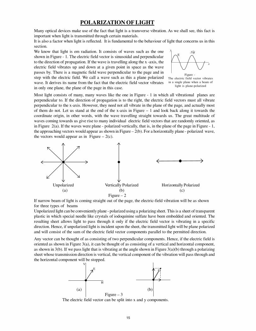
POLARIZATION OF LIGHT
Many optical devices make use of the fact that light is a transverse vibration. As we shall see, this fact is
important when light is transmitted through certain materials.
It is also a factor when light is reflected. It is fundamental to the behaviour of light that concerns us in this
section.
We know that light is em radiation. It consists of waves such as the one
shown in Figure - 1. The electric field vector is sinusoidal and perpendicular
to the direction of propagation. If the wave is travelling along the x -axis, the
electric field vibrates up and down at a given point in space as the wave
passes by. There is a magnetic field wave perpendicular to the page and in
step with the electric field. We call a wave such as this a plane polarized
wave. It derives its name from the fact that the electric field vector vibrates
in only one plane, the plane of the page in this case.
Most light consists of many, many waves like the one in Figure - 1 in which all vibrational planes are
perpendicular to. If the direction of propagation is to the right, the electric field vectors must all vibrate
perpendicular to the x-axis. However, they need not all vibrate in the plane of the page, and actually most
of them do not. Let us stand at the end of the x-axis in Figure – 1 and look back along it towards the
coordinate origin, in other words, with the wave travelling straight towards us. The great multitude of
waves coming towards us give rise to many individual electric field vectors that are randomly oriented, as
in Figure 2(a). If the waves were plane - polarized vertically, that is, in the plane of the page in Figure - 1,
the approaching vectors would appear as shown in Figure – 2(b). For a horizontally plane - polarized wave,
the vectors would appear as in Figure – 2(c).
Unpolarized Vertically Polarized Horizontally Polarized
(a) (b) (c)
Figure – 2
If narrow beam of light is coming straight out of the page, the electric-field vibration will be as shown
for three types of beams
Unpolarized light can be conveniently plane - polarized using a polarizing sheet. This is a sheet of transparent
plastic in which special needle like crystals of iodoquinine sulfate have been embedded and oriented. The
resulting sheet allows light to pass through it only if the electric field vector is vibrating in a specific
direction. Hence, if unpolarized light is incident upon the sheet, the transmitted light will be plane polarized
and will consist of the sum of the electric field vector components parallel to the permitted direction.
Any vector can be thought of as consisting of two perpendicular components. Hence, if the electric field is
oriented as shown in Figure 3(a), it can be thought of as consisting of a vertical and horizontal component,
as shown in 3(b). If we pass light that is vibrating at the angle shown in Figure 3(a)(b) through a polarizing
sheet whose transmission direction is vertical, the vertical component of the vibration will pass through and
the horizontal component will be stopped.
(a) (b)
Figure – 3
The electric field vector can be split into x and y components.
Ev/c
x
y
Figure -
The electric field vector vibrates
in a single plane when a beam of
light is plane-polarized
E
H
V
15
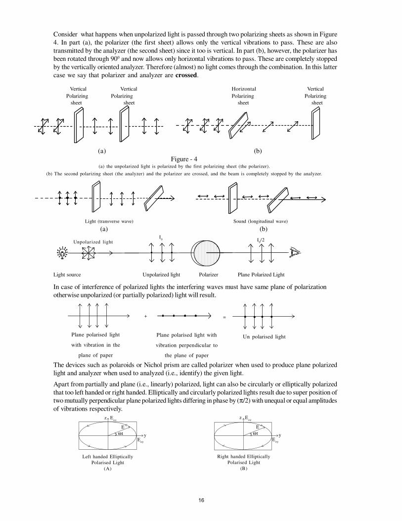
Consider what happens when unpolarized light is passed through two polarizing sheets as shown in Figure
4. In part (a), the polarizer (the first sheet) allows only the vertical vibrations to pass. These are also
transmitted by the analyzer (the second sheet) since it too is vertical. In part (b), however, the polarizer has
been rotated through 900 and now allows only horizontal vibrations to pass. These are completely stopped
by the vertically oriented analyzer. Therefore (almost) no light comes through the combination. In this latter
case we say that polarizer and analyzer are crossed.
Vertical Vertical Horizontal Vertical
Polarizing Polarizing Polarizing Polarizing
sheet sheet sheet sheet
(a) (b)
Figure - 4(a) the unpolarized light is polarized by the first polarizing sheet (the polarizer).
(b) The second polarizing sheet (the analyzer) and the polarizer are crossed, and the beam is completely stopped by the analyzer.
Light (transverse wave) Sound (longitudinal wave)
(a) (b)
Light source Unpolarized light Polarizer Plane Polarized Light
In case of interference of polarized lights the interfering waves must have same plane of polarization
otherwise unpolarized (or partially polarized) light will result.
The devices such as polaroids or Nichol prism are called polarizer when used to produce plane polarized
light and analyzer when used to analyzed (i.e., identify) the given light.
Apart from partially and plane (i.e., linearly) polarized, light can also be circularly or elliptically polarized
that too left handed or right handed. Elliptically and circularly polarized lights result due to super position of
two mutually perpendicular plane polarized lights differing in phase by (π/2) with unequal or equal amplitudes
of vibrations respectively.
I0 I
0/2Unpolarized light
+ =
Plane polarised light
with vibration in the
plane of paper
Plane polarised light with
vibration perpendicular to
the plane of paper
Un polarised light
· · · ·
z
y
Eoz
Eoy
E
ωt
Left handed Elliptically
Polarised Light
(A)
z
y
Eoz
Eoy
E
ωt
Right handed Elliptically
Polarised Light
(B)
16
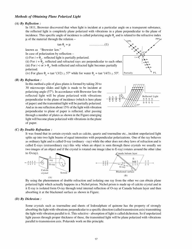
Methods of Obtaining Plane Polarized Light
(A) By Reflection :
In 1811, Brewster discovered that when light is incident at a particular angle on a transparent substance,
the reflected light is completely plane polarized with vibrations in a plane perpendicular to the plane of
incidence. This specific angle of incidence is called polarizing angle θp and is related to the refractive index
µ of the material through the relation –
tan θp = µ .................(1)
known as “Brewster law.”
In case of polarization by reflection –
(i) For i = θp, reflected light is partially polarized.
(ii) For i = θp, reflected and refracted rays are perpendicular to each other.
(iii) For i < or > θp, both reflected and refracted light becomes partially
polarized.
(iv) For glass θp = tan–1(3/2) ~ 570 while for water θ
p = tan–1(4/3) ~ 530.
(B) By Refraction :
In this method a pile of glass plates is formed by taking 20 to
30 microscope slides and light is made to be incident at
polarizing angle (570). In accordance with Brewster law the
reflected light will be plane polarized with vibrations
perpendicular to the plane of incidence (which is here plane
of paper) and the transmitted light will be partially polarized.
And as in one reflection about 15% of the light with vibration
perpendicular to plane of paper is reflected, after passing
through a number of plates as shown in the Figure emerging
light will become plane polarized with vibrations in the plane
of paper.
(C) By Double Refraction :
It was found that in certain crystals such as calcite, quartz and tourmaline etc., incident unpolarized light
splits up into two light beams of equal intensities with perpendicular polarizations. One of the ray behaves
as ordinary light and is called O-ray (ordinary - ray) while the other does not obey laws of refraction and is
called E-rays (extraordinary ray) this why when an object is seen through these crystals we usually see
two images of an object and if the crystal is rotated one image (due to E-ray) rotates around the other (due
to O-ray).
By using the phenomenon of double refraction and isolating one ray from the other we can obtain plane
polarized light which actually happens in a Nichol prism. Nichol prism is made up of calcite crystal and in
it E-ray is isolated form O-ray through total internal reflection of O-ray at Canada balsam layer and then
absorbing it at the blackened surface as shown in Figure.
(D) By Dichroism :
Some crystals such as tourmaline and sheets of Iodosulphate of quinone has the property of strongly
absorbing the light with vibrations perpendicular to a specific direction (called transmission axis) transmitting
the light with vibration parallel to it. This selective - absorption of light is called dichroism. So if unpolarized
light passes through proper thickness of these, the transmitted light will be plane polarized with vibrations
parallel to transmission axis. Polaroids work on this principle.
UPLPPL
P LPartially
i = θp
r
Reflected Light570
570
E -
ray
O-ray
IE
IO
Calcite
crystal Screen
(A)
Canada balsam layer
E-
ray
O-ray
Blackened surface
(B)
17
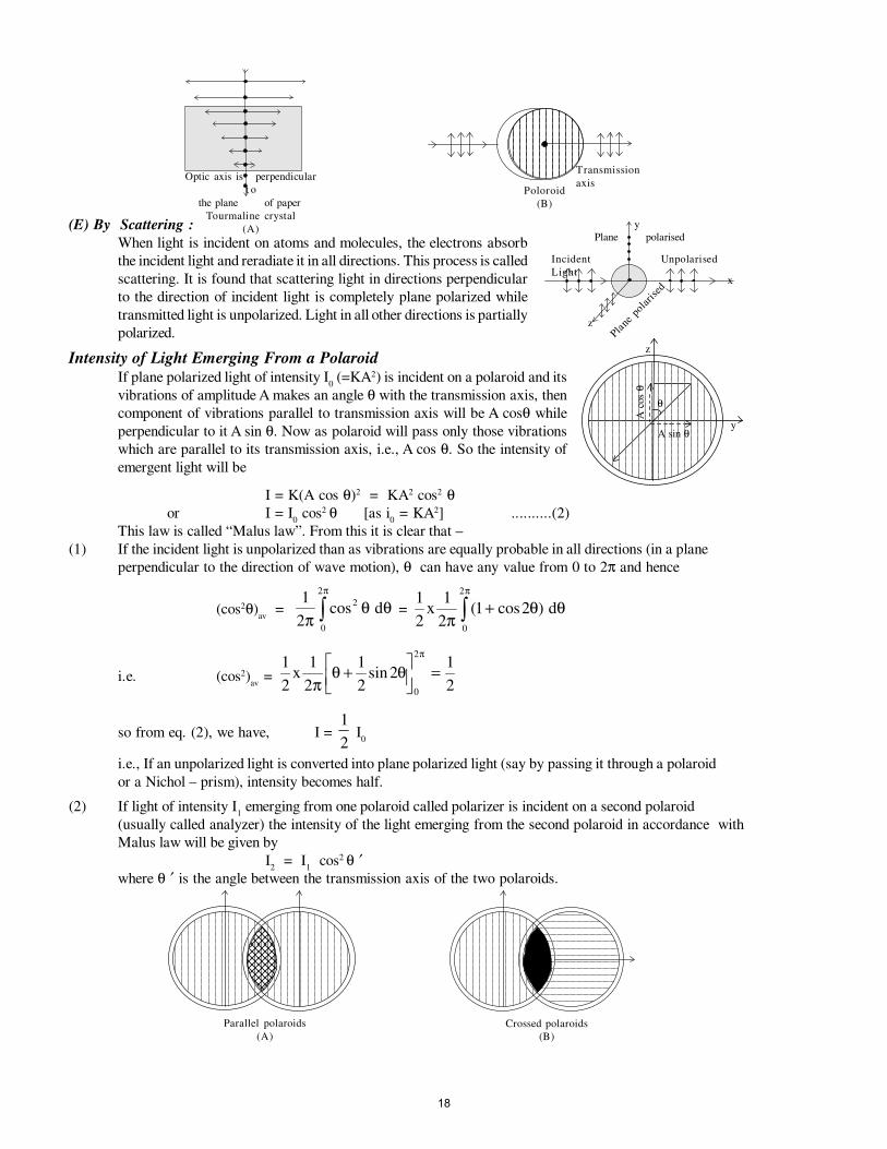
(E) By Scattering :
When light is incident on atoms and molecules, the electrons absorb
the incident light and reradiate it in all directions. This process is called
scattering. It is found that scattering light in directions perpendicular
to the direction of incident light is completely plane polarized while
transmitted light is unpolarized. Light in all other directions is partially
polarized.
Intensity of Light Emerging From a Polaroid
If plane polarized light of intensity I0 (=KA2) is incident on a polaroid and its
vibrations of amplitude A makes an angle θ with the transmission axis, then
component of vibrations parallel to transmission axis will be A cosθ while
perpendicular to it A sin θ. Now as polaroid will pass only those vibrations
which are parallel to its transmission axis, i.e., A cos θ. So the intensity of
emergent light will be
I = K(A cos θ)2 = KA2 cos2 θor I = I
0 cos2 θ [as i
0 = KA2] ..........(2)
This law is called “Malus law”. From this it is clear that –
(1) If the incident light is unpolarized than as vibrations are equally probable in all directions (in a plane
perpendicular to the direction of wave motion), θ can have any value from 0 to 2π and hence
(cos2θ)av
= 1
2
2
0
2
πθ θ
π
cos d∫ =1
2
1
21 2
0
2
x dπ
θ θπ
( cos )+∫
i.e. (cos2)av
= 1
2
1
2
1
22
1
20
2
xπ
θ θπ
+
=sin
so from eq. (2), we have, I = 1
2 I
0
i.e., If an unpolarized light is converted into plane polarized light (say by passing it through a polaroid
or a Nichol – prism), intensity becomes half.
(2) If light of intensity I1 emerging from one polaroid called polarizer is incident on a second polaroid
(usually called analyzer) the intensity of the light emerging from the second polaroid in accordance with
Malus law will be given by
I2 = I
1 cos2 θ ′
where θ ′ is the angle between the transmission axis of the two polaroids.
Optic axis is perpendicular
t o
the plane of paper
Tourmaline crystal
(A)
Transmission
axisPoloroid
(B)
Plane polarised
Incident
Light
Unpolarised
Plane
pola
rise
d
y
z
x
z
y
θ
A sin θ
A c
os
θ
Crossed polaroids
(B)
Parallel polaroids
(A)
18

So if the two polaroids have their transmission axis parallel to each other, i.e. θ ′ = 0.
I2 = I
1 cos2 θ = I
1
And if the two polaroids are crossed, i.e. have their transmission axes perpendicular to each other, θ ′ =900.
I2 = I
1 cos2900 = 0
So if an analyzer is rotated from 0 to 900 with respect to polarizer, the intensity of emergent light changes
from maximum value I1 to minimum value zero.
Identification of given Light
Polaroid or Nichol prism is used to examine whether a given light is unpolarized partially - polarized
or plane polarized. For this, the given light is passed through a polaroid (called analyzer) and the polaroid is
rotated about the incident light and emergent light is seen. Then if –
(a) There is no variation in intensity of emergent light in any position, the incident light will be unpolarized as in
case of unpolarized light the vibration of same amplitude are equally probable in all directions.
(b) There is a variation in intensity of emergent light with minimum not equal to zero, the incident light will be
partially polarized as in partially polarized light vibrations exist in all directions but are more in some directions
than in others.
(c) There is variation in intensity of emergent light with minimum equal to zero, the incident light is plane (or
linearly) polarized as in plane polarized light vibrations are confined along one direction only and so
transmission axis of analyzer will become parallel and perpendicular to vibrations twice in its one complete
rotation giving rise to maximum and zero intensity twice in each rotation.
Optical Activity
When plane polarized light passes through certain substances, the plane of polarization of light is rotated
about the directionof propagation of light through a certain angle. This phenomenon is called optical activity
or optical rotation and substances optically active.
If the optically active substance rotates the plane of polarization clockwise (looking against the direction of
light), it is said to be dextrorotatory or right handed. However, if the substance rotates the plane of polarization
anti clock wise it is called laevo–rotatory or left handed.
The optical activity of a substance is related to the asymmetry of the molecule or crystal as a whole, e.g.,
solution of cane sugar is dextrorotary due to asymmetrical molecular structure while crystals of quartz are
dextro or levo rotatory due to structural asymmetry which vanishes when quartz is fused.
Optical activity of a substance is measured with the help of, polarimeter in terms of specific rotation which
is defined as the rotation produced by a solution of length 10cm (1 dm) and unit concentration (i.e.,
1 g/cc) for given wavelength of light at a given temperature,
i.e., [ ]αθλ
t C LC0 =
where θ is the rotation in length L at concentration C.
Unpolarised
Light
Plane polarised
Light
Substance
Polariser AnalyzerLeavo
Rotatory
Dextro
Rotatory
Polarimeter
·
19
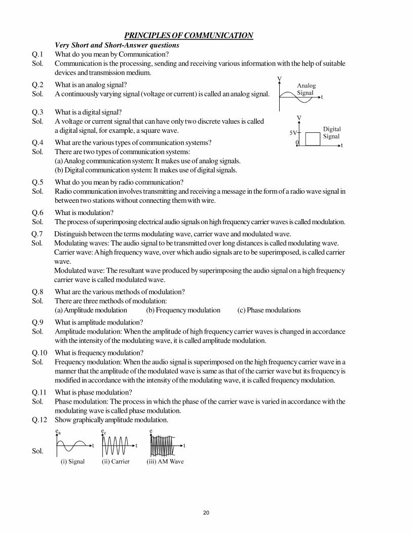
PRINCIPLES OF COMMUNICATION
Very Short and Short-Answer questions
Q.1 What do you mean by Communication?
Sol. Communication is the processing, sending and receiving various information with the help of suitable
devices and transmission medium.
Q.2 What is an analog signal?
Sol. A continuously varying signal (voltage or current) is called an analog signal.
Q.3 What is a digital signal?
Sol. A voltage or current signal that can have only two discrete values is called
a digital signal, for example, a square wave.
Q.4 What are the various types of communication systems?
Sol. There are two types of communication systems:
(a) Analog communication system: It makes use of analog signals.
(b) Digital communication system: It makes use of digital signals.
Q.5 What do you mean by radio communication?
Sol. Radio communication involves transmitting and receiving a message in the form of a radio wave signal in
between two stations without connecting them with wire.
Q.6 What is modulation?
Sol. The process of superimposing electrical audio signals on high frequency carrier waves is called modulation.
Q.7 Distinguish between the terms modulating wave, carrier wave and modulated wave.
Sol. Modulating waves: The audio signal to be transmitted over long distances is called modulating wave.
Carrier wave: A high frequency wave, over which audio signals are to be superimposed, is called carrier
wave.
Modulated wave: The resultant wave produced by superimposing the audio signal on a high frequency
carrier wave is called modulated wave.
Q.8 What are the various methods of modulation?
Sol. There are three methods of modulation:
(a) Amplitude modulation (b) Frequency modulation (c) Phase modulations
Q.9 What is amplitude modulation?
Sol. Amplitude modulation: When the amplitude of high frequency carrier waves is changed in accordance
with the intensity of the modulating wave, it is called amplitude modulation.
Q.10 What is frequency modulation?
Sol. Frequency modulation: When the audio signal is superimposed on the high frequency carrier wave in a
manner that the amplitude of the modulated wave is same as that of the carrier wave but its frequency is
modified in accordance with the intensity of the modulating wave, it is called frequency modulation.
Q.11 What is phase modulation?
Sol. Phase modulation: The process in which the phase of the carrier wave is varied in accordance with the
modulating wave is called phase modulation.
Q.12 Show graphically amplitude modulation.
Sol.
20
Q.13 Define modulation factor(modulation index,depth of modulation).
Sol. Modulation factor is defined as the ratio of the change of amplitude of the carrier wave to the amplitude
of the normal carrier wave, i.e.,
wavecarriernormalofAmplitude
wavecarrierofchangeAmplitudem
a=
Q.14 What is the value of bandwidth in amplitude modulation?
Sol. In amplitude modulation, bandwidth is twice the signal frequency.
Q.15 Define the term frequency deviation.
Sol. In frequency modulation the maximum variation of the frequency of modulated wave from the carrier
frequency is called frequency deviation.
Q.16 What are the limitations of amplitude modulation?
Sol.(i) The efficiency of amplitude modulation is low.
(ii) Messages cannot be transmitted over long distances using amplitude modulation.
(iii) The reception is generally noisy.
Q.17 Write an expression for the modulation index for frequency modulation.
Sol. Modulation index in case of frequency modulation is given by
mf =
sf
δ
where δ is frequency deviation and fs is modulating frequency.
Q.18 Can the value of modulation index be greater than unity?
Sol. Yes, in case of frequency modulation the value of modulation index can be greater than unity.
Q.19 Write the advantages of frequency modulation.
Sol.(i) Frequency modulation transmission is highly efficient.
(ii) Frequency modulation can be used for the stereo sound transmission due to the presence of a large
number of sidebands.
Q.20 Give two disadvantages of frequency modulation.
Sol.(i) The frequency modulation transmitting and receiving equipments are very complex as compared to
those used in amplitude modulation transmission.-
(ii) A.wider frequency channel is required in frequency modulation transmission.
Q.21 What is the importance of modulation index?
Sol. The modulation index determines the strength and quality of the transmitted signal. For strong and clear
reception the modulation index must be high.
Q.22 What do you mean by bandwidth?
Sol. The frequency range in which a transmitting system makes transmission is called bandwidth.
Q.23 Give expressions for bandwidth in
(a) AM transmission (b) FM transmission
Sol (a) AM transmission:
Bandwidth = 2 × maximum frequency of modulating signal.
(b) FM transmission:
Bandwidth = 2n × frequency of modulating signal
where n is the number of significant sidebands.
Q.24 What is demodulation?
Sol. The reverse process of modulation, i.e. the process of recovering the audio signal from the modulated
wave is known as demodulation or detection.
21
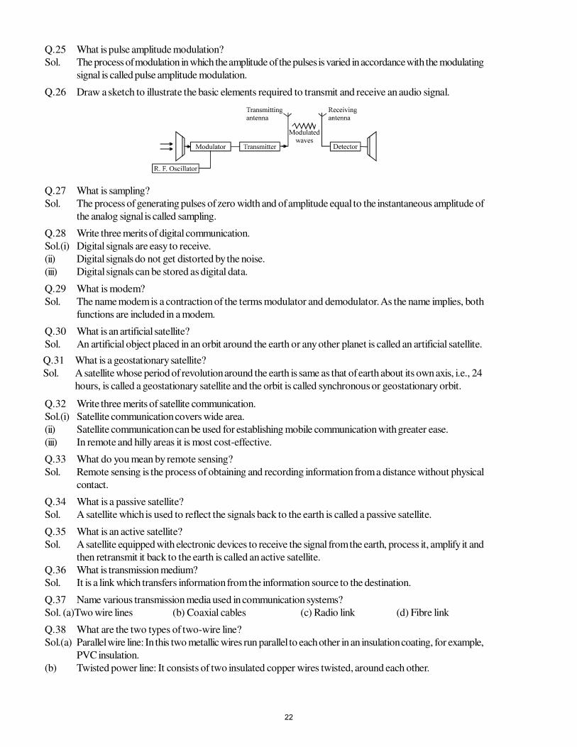
Q.25 What is pulse amplitude modulation?
Sol. The process of modulation in which the amplitude of the pulses is varied in accordance with the modulating
signal is called pulse amplitude modulation.
Q.26 Draw a sketch to illustrate the basic elements required to transmit and receive an audio signal.
Q.27 What is sampling?
Sol. The process of generating pulses of zero width and of amplitude equal to the instantaneous amplitude of
the analog signal is called sampling.
Q.28 Write three merits of digital communication.
Sol.(i) Digital signals are easy to receive.
(ii) Digital signals do not get distorted by the noise.
(iii) Digital signals can be stored as digital data.
Q.29 What is modem?
Sol. The name modem is a contraction of the terms modulator and demodulator. As the name implies, both
functions are included in a modem.
Q.30 What is an artificial satellite?
Sol. An artificial object placed in an orbit around the earth or any other planet is called an artificial satellite.
Q.31 What is a geostationary satellite?
Sol. A satellite whose period of revolution around the earth is same as that of earth about its own axis, i.e., 24
hours, is called a geostationary satellite and the orbit is called synchronous or geostationary orbit.
Q.32 Write three merits of satellite communication.
Sol.(i) Satellite communication covers wide area.
(ii) Satellite communication can be used for establishing mobile communication with greater ease.
(iii) In remote and hilly areas it is most cost-effective.
Q.33 What do you mean by remote sensing?
Sol. Remote sensing is the process of obtaining and recording information from a distance without physical
contact.
Q.34 What is a passive satellite?
Sol. A satellite which is used to reflect the signals back to the earth is called a passive satellite.
Q.35 What is an active satellite?
Sol. A satellite equipped with electronic devices to receive the signal from the earth, process it, amplify it and
then retransmit it back to the earth is called an active satellite.
Q.36 What is transmission medium?
Sol. It is a link which transfers information from the information source to the destination.
Q.37 Name various transmission media used in communication systems?
Sol. (a)Two wire lines (b) Coaxial cables (c) Radio link (d) Fibre link
Q.38 What are the two types of two-wire line?
Sol.(a) Parallel wire line: In this two metallic wires run parallel to each other in an insulation coating, for example,
PVC insulation.
(b) Twisted power line: It consists of two insulated copper wires twisted, around each other.
22
Q.39 What is the main drawback of 2-wire line.
Sol. At microwave frequencies, the energy losses in a 2-wire line become very large. The attenuation of
signals increases with the length of the wire. Therefore, the 2-wire line is used for transmission of signals
over a small distance.
Q.40 What is a coaxial cable?
Sol. A coaxial cable consists of a central copper wire surrounded by a PVC insulation over which there is a
sleeve of copper mesh. Finally it is covered with an outer thick PVC material.
Q.41 What is the use of copper mesh in a coaxial cable?
Sol. In a coaxial cable, when the central copper wire carries the signal, the copper mesh shields it electrically
from the external electrical disturbances.
Q.42 What is an optical fibre?
Sol. It is a device which is based on the phenomenon of total internal reflection. It consists of a very thin glass
or quartz fibre which is coated with a material of lower refractive index.
Q.43 What is the use of optical fibres?
Sol. The optical fibres are used to transmit light signals from one place to another without any appreciable
loss in the intensity of light.
Q.44 What are the two types of optical fibres?
Sol. The optical fibres are of the following two types:
(a) Monomode optical fibre
(b) Multimode optical fibre
Q.45 What is cladding?
Sol. The glass coating of relatively lower refractive index, surrounding the glass case in optical fibre is called
cladding.
Q.46 What do you mean by angle of acceptance in optical fibre?
Sol. The maximum angle of incidence in air for which light is totally reflected at the glass core-cladding
interface is called the angle of acceptance.
Q.47 Write an expression for the angle of acceptance in an optical fibre.
Sol. If i is the angle of acceptance then
sin i = 22
21
µ−µ
Where µ1 is the refractive index of glass core and µ
2 is the refractive index of cladding.
Q.48 What is optical communication?
Sol. The phenomenon of transmission of information from one place to another using optical carrier waves is
called optical communication.
Q.49 What does LASER stands for?
Sol. The term LASER stands for
Light amplification by stimulated emission of radiation.
Q.50 Write the main characteristics of a laser beam?
Sol. The main characteristics of a laser beam are - highly monochromatic, highly coherent and perfectly
parallel. A laser beam can be sent to a far off place and be reflected back without any significant loss of
intensity.
Q.51 What is stimulated emission?
Sol. If an atom or a molecule is in an excited state, it may make a transition to a lower energy state by the
‘impact’ of another photon of the required energy. This process is known as stimulated emission, to
distinguish it from spontaneous emission which occurs on its own.
23
Q.52 What do you mean by optical pumping?
Sol. It is the process of raising atoms from a lower energy state to a higher energy state by induced absorption.
Q.53 What is light modulation?
Sol. The process of modulating a light beam from an optical source in accordance with the information signal
is called light modulation.
Q.54 Why do we need modulation.
Sol. Audio signals are weak signals. So they can not be transmitted directly over large distances. Moreover
the wavelength associated with audio signals is very large. Hence antenna of large dimensions (–λ) is
required. To overcome these difficulties, modulation is needed. .
Q.55 Which modulation is used for commercial broadcasting of voice signal?
Sol. Amplitude modulation.
Q.56 Which modulation is used in TV broadcast and why?
Sol. TV broadcast requires larger bandwidth and hence frequency modulation is used.
Q.57 What is the approximate dimension of an antenna?
Sol. Of the order of the wavelength of the signal.
Q.58 What is FAX?
Sol. The electronic transmission of a document to a distant place via telephone line is known as FAX or
fascimile.
Q.59 Name the layer of earth’s atmosphere which is most useful in long distance radio communication. Why?
Sol. Ionosphere. It reflects the radio waves back to the earth.
Q.60 What is the highest frequency that can be reflected back by the ionosphere?
Sol. 30MHz.
Q.61 Distinguish between ground wave and sky wave?
Sol. Audio signals emitted from a certain location on the earth can be received at another location by two
different ways- .
(i) If the waves travel along the surface of the earth from one place to another, it is called ground wave.
Ground wave transmission is limited to 1500KHz.
(ii) If the wave is transmitted towards the sky and reaches another location after getting reflected from the
ionosphere, it is called sky wave. Sky wave transmission is limited to a frequencyof 30MHz.
Q.62 What is the frequency range of UHF band?
Sol. Ultra high frequency (UHF) band has frequency ranging from 300MHz to 3000MHz.
Q.63 Which waves are used for long distance radio telecast?
Sol. Short waves are used for long distance radio telecast as they can be easily reflected back to the earth by
the ionosphere.
Q.64 What is amplitude modulated (AM) Band?
Sol. Amplitude modulated band consists of radiowaves of frequencies less than 30MHz.
Q.65 Is it necessary to use satellites for long distance TV transmission? Give one reason.
Sol. TV signals cannot be sent directly to large distances. Further, TV signals have very high frequencies
which are not reflected by the ionosphere. Therefore the signals from the broadcasting station are beamed
towards a geostationary satellite, which relays them back to the earth. Since the satellite is high above, it
covers large distances on the earth.
Q.66 Write an expression for the distance upto which the TV signals can be directly received from a TV tower
of height h.
Sol. distance d = hR2
Where R is radius of the earth and h is the height of the antenna.
24
Q.67 Which part of the electromagnetic spectrum is used in operating a radar?
Sol. Microwaves (109 – 1012 Hz)
Q.68 What do you understand by HF and MF bands?
Sol. HF stands for high frequency band (3–30 MHz).
MF stands for medium frequency band (300–3000 kHz).
Q.69 Why is ground wave transmission limited to a frequency of 1500 kHz.
Sol. The attenuation of ground waves increase with increase in frequency due to interaction with objects in its
path. So ground wave transmission is limited to a frequency of 1500 kHz.
Q.70 Why sky waves are not used in the transmission of TV signals?
Sol. TV signals have frequency much higher than 30 MHz. Such high frequency signals cannot be reflected
by the ionosphere. Therefore, sky waves are not used in the transmission of TV signals.
Q.71 What is FM Band?
Sol The electromagnetic waves in the frequency range 80 MHz to 200 MHz constitute frequency modulated
(FM) band.
Q.72 What is a geostationary satellite?
Sol. A satellite which appears to be fixed at a place above the earth is called a geostationary satellite. It has
the time period of revolution around the earth equal to the rotational period of the earth about its axis,
i.e., 24 hour
Q.73 Name the electromagnetic wave used in satellite communication.
Sol. Microwave.
Q.74 Name two primary requirements for optical transmission.
Sol. (i) Optical source (ii) Optical fibre.
Q.75 What is the bandwidth required to telecast picture through a TV channel?
Sol. 4.7MHz per channel.
Q.76 What is an optical source? Name any two optical sources.
Sol. Light source used in optical communication is called an optical source. Examples- LED and LASER.
Q.77 Write three advantages of LASER over LED as optical source.
Sol.(i) Low beam divergence (ii) Greater transmission distance (iii) High modulation rate
Q.78 What is an optical detector? Name three optical detectors.
Sol. It is a device that generates electrical signals when light falls on it. Examples - Silicon photodiode,
avalanche photodiode, photo transistor, etc.
Q.79 What do you mean by sensitivity and responsivity of a detector?
Sol. Sensitivity is a measure of the ability of a detector and determines how weak a signal can be detected.
The ability of the detector to respond quickly to the changing light pulses is called responsivity.
Q.80 What is photonics?
Sol. Photonics is a subject that deals with generation and detection of photons.
Q.81 What is LED?
Sol. An LED works on the process of spontaneous emission when a p-n junction is forward biased. If a p-
n junction diode is forward biased, energy is released due to recombination of electrons and holes. In
case of silicon and germanium diodes, the energy released is in infrared region. However, if the diode is
made of gallium arsenide or indium phosphide, the energy released is in visible range.
25
Q.82 Derive an expression for the distance upto which the TV, signals can be directly received from a TV
tower of height h.
Sol. The figure shows a TV transmitting antenna of height AB = h located at A on the surface of the earth of
radius R. The signal transmitted can be received within a circle of radius AS on the surface of the earth.
Now in the right angled triangle OBS.
OB2 = OS2 + BS2
Now,
BS ≈ AS = d. So,
(R+ h)2 = d2 + R2
d2 = h2 + 2hR
Since h < < R, neglecting h2 we have d2=2hR
or d = hR2
LONG-ANSWER QUESTIONS
Q.1 Why is modulation necessary in a communication system?
Sol. Modulation is necessary in a communication system due to the following reasons:
(a) Antenna Length: It can be shown theoretically that in order to transmit a signal effectively, the length of
the transmitting antenna should be of the order of the wavelength of the signal.The audio frequencies
range from 20 Hz to 20 kHz: If they are transmitted directly, the length of the required antenna would be
very large. For example, for a frequency of 20 kHz, the antenna length would be (3 × 10⁸)/(20 × 103)
= 15,000 metres, which is too large. Thus it is not practicable to transmit audio signals directly.
A carrier wave, on the other hand, has a much higher frequency, say 1000 kHz. This would require an
antenna of about 300 metres length, which can be conveniently installed.
(b) The energy of a wave depends on its frequency-greater the frequency of a wave, greater is the energy
possessed by it. The audio signal frequencies are low and hence their energies are small. Therefore, they
cannot be transmitted over large distances directly. However, superimposing them on high frequency
carrier waves makes it possible to transmit them over long distances.
(c) Long distance transmission is carried out without wires, i.e., the signal is radiated into space. At low
audio frequencies the efficiency of radiation is not good. After modulation the transmission is at high
carrier frequencies, which is quite efficient.
Q.2 Draw a circuit diagram for demodulation (detection) and explain its working.
Sol. The basic circuit using a junction diode is shown:
The input circuit consists of a parallel combination of an inductor L and a variable capacitor C. This
circuit is called tuning circuit which is used to select the desired modulated radio frequency. The output
of the diode is a series of positive half cycles of radio frequency current pulses. The peaks of these pulses
vary in accordance with the modulating audio signal. This rectified output is fed to the parallel combination
of a capacitor C1 and a resistor R. The capacitor C
1 acts as a bypass for carrier waves and the audio
frequency voltage appears across the resistor R.
Q.3(a) Explain the use of a geostationary satellite for long distance communication.
(b) Explain remote sensing.
Sol.(a) For long distance transmission, microwaves are used as carrier waves since they can pass through the
atmosphere without significant loss of energy. This is due to their small wavelengths. Signals from the
26
broadcasting station are beamed towards an artificial earth satellite which reflects them back to the earth.
Since the satellite is at a large height, it can send back the signals to a large part of the earth’s surface. For
a satellite to be useful for sending signals to particular regions, its orbit must be such that it appears stationary
relative to the earth’s surface. Such a satellite is called a geostationary satellite. Its time period is 24 hours.
It can be shown that the height of such a satellite above the earths’ surface is about 36,000 km. Communication
links all around the earth have been established by putting many geostationary satellites in the equatorial
plane at this height.
(b) Remote sensing. It is the technique of obtaining information about an object or some region from a large
distance. For this purpose a remote sensing satellites, also called an active satellite, is used. Such a
satellite is equipped with various instruments (such as cameras, microwaves scanners etc.) to enable it to
record and send the desired information. The satellite is placed in sun-synchronous orbit around the
earth. This makes it possible to have similar lighting conditions every time it passes over the particular
region of the earth. Constant lighting angles help the observations about that region to be more standard
and easier to interpret. In recent years, satellite remote sensing has become very important. One major
application is to gather information (e.g. temperature, nature, size etc.) about remote, inaccessible regions
of the earth and to estimate the damage caused by floods, droughts, etc.
Q.4 State the principle of an optical fibre. Explain in brief the various types of optical fibres.
Sol. Optical fibres are based on the phenomenon of total internal reflection.
Consider a ray BO incident on the glass core from air at an angle i such
that the ray of light inside the core meets the core-cladding interface at
an angle greater than the critical angle for it. As a result, the ray of light
undergoes total internal reflection. The path of ray is shown in figure A.
Different types of optical fibres
are-
1. Monomode optical fibre - It has a narrow core of diameter about 5 mm surrounded by a relatively big
cladding (125 mm in diameter). In such optical fibres, there is practically no loss in the intensity of the
output light signal.2. Multimode optical fibre - These are further classified as-
(i) Step index multimode fibre: In this type of optical fibre the diameter of the core is about 50 mm which
is very large in comparison with monomode optical fibre.
Figure B shows the path of two light waves of wavelength λ1 and λ
2.
Since the refractive index of a material depends on the wavelength, the
two light waves will reach the other end following different and unequal
paths. As a result a faulty and distorted signal
is obtained.
(ii) Graded index multimode fibre: In this type of optical fibre, the refractive index decreases smoothly
from its centre to the outer surface of the fibre. As such, there is no boundary between the core and
cladding. At the centre, the refractive index is 1.52, which decreases to 1.48 at the outer surface. In a
graded index multimode fibre, all the light waves, regardless of their wavelength, arrive at other end of
the fibre at the same time.
Q.5 State the principle of LASER. Explain the experimental arrangement and theory of ruby laser with the
help of energy level diagram.
Sol. LASER is based on the principle that in the atomic systems possessing metastable states, one can cause
population inversion and then the process of stimulated emission can be used to produce highly coherent,
highly monochromatic and perfectly parallel beam of light.
Ruber Laser is a solid state laser. The main component of it is a ruby rod. Ruby is a crystal of aluminium
oxide doped with 0.05% of chromium oxide. These rods are about 5 cm in length and 0.5 cm in diameter.
The end faces of the rod are made parallel and coated with silver, such that one face becomes fully
reflecting while the other face is partially reflecting so as to allow the laser beam to emerge out of the ruby
27
rod. The ruby rod is placed along the axis of a Xenon flash tube. The flash tube provides the necessary
pumping energy to the ruby rod. The rod is kept cool by circulating liquid nitrogen around it.
Ruby laser is a three energy level system. The three energy levels of chromium ion are the ground state
E0 the metastable state E
1 and a higher energy level E
2. Initially the atoms are distributed in various energy levels.
When the Xenon lamp is switched on, it produces a flash intense light of wavelength 5500Å which acts as pumping
radiation for chromium ions. The atoms are raised from the ground state
to the higher energy state E2. The electrons cannot stay in excited state for more than 10–8 s and they
drop to either energy level E1 or directly to ground state E
0. The energy released during the process is
lost to ruby rod and before it raises its temperature it is cooled by liquid nitrogen. In a short duration
there is population inversion i.e., state E1 (metastable) becomes more populated.
Now, once a photon is produced due to transition from the
metastable state E1 to the ground state E
0, it stimulates the
emission of another photon of the same energy, phase and
direction. The emitted photons suffer multiple reflection between
the two polished ends and stimulate further emissions. The
process of amplification continues till an intense beam of laser
emerges out from the partially coated
face of the rod.
Q.6 Write short notes on
(a) Modem (b) Fax.
Sol.(a) MODEM: As the name implies, a modem can perform both the functions of modulation and demodulation. In the transmitting mode, modem converts digital data into analog signal for use in modulating a carrier by a signal. At the receiver end reverse of it takes place. Thus modems are placed at both the ends of communication circuits. Operation of
modem are classified into the following three modes:
(i) Simplex mode - This type of modem provides transmission in only one direction.
(ii) Half duplex mode - This type of modem are able to transfer data in both directions. The flow of data in one
direction takes place at one time and in the opposite direction at a second time. It requires one transmission
bidirectional channel.
(iii) Full duplex mode - In this mode of operation, transmission takes place in both directions at the same time. In
this case two transmission channels are required.
(b) FAX (FASCIMILE). The electronic transmission of a document to a distant place via telephone line is known
as fascimile or Fax. In fascimile transmission an exact reproduction of a document is produced at
the receiving end.
In order to send Fax copy of some document, the sender dials in the phone number of Fax machine at
the receiver’s end. At the sender’s end Fax machine is in transmitting mode while at the receiver end it is
in receiving mode. In the receiving mode, only the printer is active to receive the incoming signal. When
the document is fed into the machine, the scanner scans the document. When an intense beam of light
falls on the scanned document, the amount of light that bounces back is detected by the sensor. When
ink is present, little light is.reflected which creates a pulse of low voltage while from the blank paper a
pulse of high voltage is produced. A modem inside the Fax corverts these digital pulses into analog signals which are
then transmitted via the telephone link. The modem at the other end converts back the analog signal into digital pulses
which are printed by the printer of the Fax and produce Fax copy of the original document.
28
STUDY PACKAGE
Target: IIT-JEE (Advanced)
SUBJECT: PHYSICS
TOPIC: XII P5. Magnetic Effects of Electric Current
Index:
1. Key Concepts
2. Exercise I
3. Exercise II
4. Exercise III
5. Exercise IV
6. Answer Key
7. 34 Yrs. Que. from IIT-JEE
8. 10 Yrs. Que. from AIEEE
1
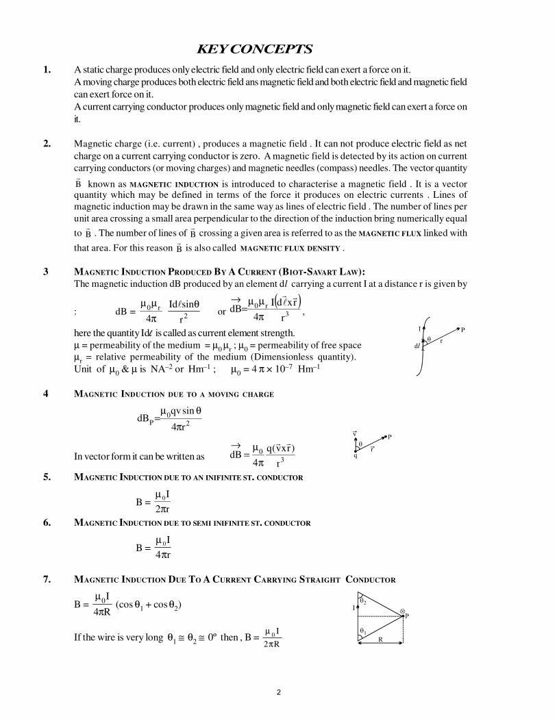
KEY CONCEPTS
1. A static charge produces only electric field and only electric field can exert a force on it.
A moving charge produces both electric field ans magnetic field and both electric field and magnetic field
can exert force on it.
A current carrying conductor produces only magnetic field and only magnetic field can exert a force on
it.
2. Magnetic charge (i.e. current) , produces a magnetic field . It can not produce electric field as net
charge on a current carrying conductor is zero. A magnetic field is detected by its action on current
carrying conductors (or moving charges) and magnetic needles (compass) needles. The vector quantityB known as MAGNETIC INDUCTION is introduced to characterise a magnetic field . It is a vectorquantity which may be defined in terms of the force it produces on electric currents . Lines of
magnetic induction may be drawn in the same way as lines of electric field . The number of lines per
unit area crossing a small area perpendicular to the direction of the induction bring numerically equal
to B . The number of lines of
B crossing a given area is referred to as the MAGNETIC FLUX linked with
that area. For this reason B is also called MAGNETIC FLUX DENSITY .
3 MAGNETIC INDUCTION PRODUCED BY A CURRENT (BIOT-SAVART LAW):
The magnetic induction dB produced by an element dl carrying a current I at a distance r is given by
: dB = π
µµ
4
r0
2r
sindI θ or
( )3
r0
r
rxdI
4dB
π
µµ=
→,
here the quantity Idl is called as current element strength.
µ = permeability of the medium = µ0 µ
r ; µ
0 = permeability of free space
µr = relative permeability of the medium (Dimensionless quantity).
Unit of µ0 & µ is NA–2 or Hm–1 ; µ
0 = 4 π × 10–7 Hm–1
4 MAGNETIC INDUCTION DUE TO A MOVING CHARGE
20
Pr4
sinqvdB
π
θµ=
In vector form it can be written as 3
0
r
)rxv(q
4dB
π
µ=
→
5. MAGNETIC INDUCTION DUE TO AN INIFINITE ST. CONDUCTOR
B = µ
π0
2
I
r
6. MAGNETIC INDUCTION DUE TO SEMI INIFINITE ST. CONDUCTOR
B = µ
π0I
r4
7. MAGNETIC INDUCTION DUE TO A CURRENT CARRYING STRAIGHT CONDUCTOR
B = R4
I0
π
µ(cos θ
1 + cos θ
2)
If the wire is very long θ1 ≅ θ
2 ≅ 0º then , B =
R2
I0
π
µ
2
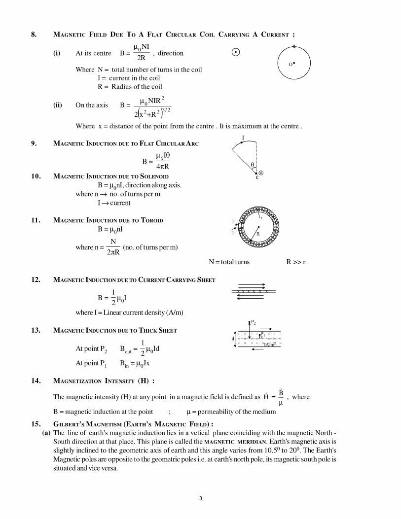
8. MAGNETIC FIELD DUE TO A FLAT CIRCULAR COIL CARRYING A CURRENT :
(i) At its centre B = R2
IN0
µ , direction
Where N = total number of turns in the coil
I = current in the coil
R = Radius of the coil
(ii) On the axis B =
( ) 2/322
20
Rx2
RIN
+
µ
Where x = distance of the point from the centre . It is maximum at the centre .
9. MAGNETIC INDUCTION DUE TO FLAT CIRCULAR ARC
B = R4
I
π
θµ0
10. MAGNETIC INDUCTION DUE TO SOLENOID
B = µ0nI, direction along axis.
where n → no. of turns per m.
I → current
11. MAGNETIC INDUCTION DUE TO TOROID
B = µ0nI
where n = N
R2π (no. of turns per m)
N = total turns R >> r
12. MAGNETIC INDUCTION DUE TO CURRENT CARRYING SHEET
B = 1
2µ
0I
where I = Linear current density (A/m)
13. MAGNETIC INDUCTION DUE TO THICK SHEET
At point P2
Bout
=1
2µ
0Id
At point P1
Bin
= µ0Jx
14. MAGNETIZATION INTENSITY (H) :
The magnetic intensity (H) at any point in a magnetic field is defined as H =
B
µ , where
B = magnetic induction at the point ; µ = permeability of the medium
15. GILBERT'S MAGNETISM (EARTH'S MAGNETIC FIELD) :
(a) The line of earth's magnetic induction lies in a vetical plane coinciding with the magnetic North -
South direction at that place. This plane is called the MAGNETIC MERIDIAN. Earth's magnetic axis is
slightly inclined to the geometric axis of earth and this angle varies from 10.50 to 200. The Earth's
Magnetic poles are opposite to the geometric poles i.e. at earth's north pole, its magnetic south pole is
situated and vice versa.
3
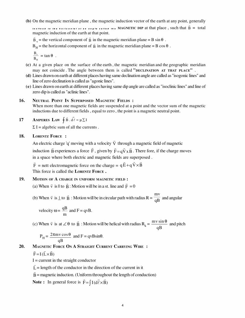
(b) On the magnetic meridian plane , the magnetic induction vector of the earth at any point, generally
i n c l i n e d t o t h e h o r i z o n t a l a t a n a n g l e c a l l e d t h ei n c l i n e d t o t h e h o r i z o n t a l a t a n a n g l e c a l l e d t h ei n c l i n e d t o t h e h o r i z o n t a l a t a n a n g l e c a l l e d t h ei n c l i n e d t o t h e h o r i z o n t a l a t a n a n g l e c a l l e d t h e MAGNETIC DIP at that place , such that B = total
magnetic induction of the earth at that point.B v
= the vertical component ofB in the magnetic meridian plane = B sin θ .
BH
= the horizontal component ofB in the magnetic meridian plane = B cos θ .
B
B
v
H
= tan θ .
(c) At a given place on the surface of the earth , the magnetic meridian and the geographic meridian
may not coincide . The angle between them is called "DECLINATION AT THAT PLACE" .
(d) Lines drawn on earth at different places having same declination angle are called as "isogonic lines" and
line of zero declination is called as "agonic lines".
(e) Lines drawn on earth at different places having same dip angle are called as "isoclinic lines" and line of
zero dip is called as "aclinic lines".
16. NEUTRAL POINT IN SUPERPOSED MAGNETIC FIELDS :
When more than one magnetic fields are suspended at a point and the vector sum of the magnetic
inductions due to different fields , equal to zero , the point is a magnetic neutral point.
17 AMPERES LAW B d I.
→
∫ = ∑µ
Σ I = algebric sum of all the currents .
18. LORENTZ FORCE :
An electric charge 'q' moving with a velocity V through a magnetic field of magnetic
induction B experiences a force
F , given by
F qV x B= . There fore, if the charge moves
in a space where both electric and magnetic fields are superposed .F = nett electromagnetic force on the charge = q E q V B
+ ×
This force is called the LORENTZ FORCE .
19. MOTION OF A CHARGE IN UNIFORM MAGNETIC FIELD :
(a) When v is || to
B : Motion will be in a st. line and
F = 0
(b) When v is | to
B : Motion will be in circular path with radius R =
mv
qB and angular
velocity ω = qB
m and F = qvB.
(c) When v is at ∠ θ to
B : Motion will be helical with radius R
k =
mv
qB
sin θ and pitch
PH = 2π θmv
qB
cos and F = qvBsinθ.
20. MAGNETIC FORCE ON A STRAIGHT CURRENT CARRYING WIRE : F I L B= ×( )
I = current in the straight conductorL = length of the conductor in the direction of the current in itB = magnetic induction. (Uniform throughout the length of conduction)
Note : In general force is
F I d B= ×∫ ( )
4
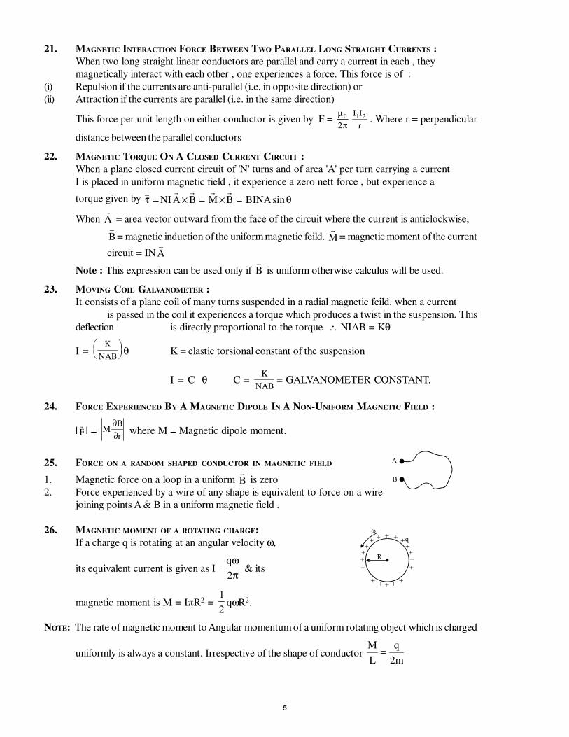
21. MAGNETIC INTERACTION FORCE BETWEEN TWO PARALLEL LONG STRAIGHT CURRENTS :
When two long straight linear conductors are parallel and carry a current in each , they
magnetically interact with each other , one experiences a force. This force is of :
(i) Repulsion if the currents are anti-parallel (i.e. in opposite direction) or
(ii) Attraction if the currents are parallel (i.e. in the same direction)
This force per unit length on either conductor is given by F = µ
π0
2
I I
r
1 2 . Where r = perpendicular
distance between the parallel conductors
22. MAGNETIC TORQUE ON A CLOSED CURRENT CIRCUIT :
When a plane closed current circuit of 'N' turns and of area 'A' per turn carrying a current
I is placed in uniform magnetic field , it experience a zero nett force , but experience a
torque given by τ θ= × = × =NI A B M B BINA sin
When A = area vector outward from the face of the circuit where the current is anticlockwise,B = magnetic induction of the uniform magnetic feild.
M = magnetic moment of the current
circuit = INA
Note : This expression can be used only if B is uniform otherwise calculus will be used.
23. MOVING COIL GALVANOMETER :
It consists of a plane coil of many turns suspended in a radial magnetic feild. when a current
is passed in the coil it experiences a torque which produces a twist in the suspension. This
deflection is directly proportional to the torque ∴ NIAB = Kθ
I = K
NAB
θ K = elastic torsional constant of the suspension
I = C θ C =K
NAB= GALVANOMETER CONSTANT..
24. FORCE EXPERIENCED BY A MAGNETIC DIPOLE IN A NON-UNIFORM MAGNETIC FIELD :
|F | = M
B
r
∂
∂ where M = Magnetic dipole moment.
25. FORCE ON A RANDOM SHAPED CONDUCTOR IN MAGNETIC FIELD
1. Magnetic force on a loop in a uniform B is zero
2. Force experienced by a wire of any shape is equivalent to force on a wire
joining points A & B in a uniform magnetic field .
26. MAGNETIC MOMENT OF A ROTATING CHARGE:
If a charge q is rotating at an angular velocity ω,
its equivalent current is given as I =qω
π2 & its
magnetic moment is M = IπR2 = 1
2qωR2.
NOTE: The rate of magnetic moment to Angular momentum of a uniform rotating object which is charged
uniformly is always a constant. Irrespective of the shape of conductor M
L
q
m=
2
5
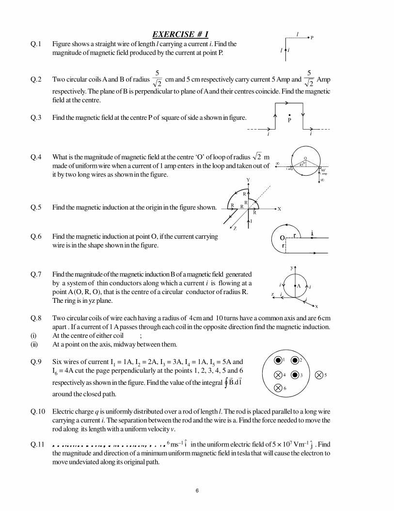
EXERCISE # IQ.1 Figure shows a straight wire of length l carrying a current i. Find the
magnitude of magnetic field produced by the current at point P.
Q.2 Two circular coils A and B of radius 2
5 cm and 5 cm respectively carry current 5 Amp and
2
5 Amp
respectively. The plane of B is perpendicular to plane of A and their centres coincide. Find the magnetic
field at the centre.
Q.3 Find the magnetic field at the centre P of square of side a shown in figure.
Q.4 What is the magnitude of magnetic field at the centre ‘O’ of loop of radius 2 m
made of uniform wire when a current of 1 amp enters in the loop and taken out of
it by two long wires as shown in the figure.
Q.5 Find the magnetic induction at the origin in the figure shown.
Q.6 Find the magnetic induction at point O, if the current carrying
wire is in the shape shown in the figure.
Q.7 Find the magnitude of the magnetic induction B of a magnetic field generated
by a system of thin conductors along which a current i is flowing at a
point A (O, R, O), that is the centre of a circular conductor of radius R.
The ring is in yz plane.
Q.8 Two circular coils of wire each having a radius of 4 cm and 10 turns have a common axis and are 6 cm
apart . If a current of 1 A passes through each coil in the opposite direction find the magnetic induction.
(i) At the centre of either coil ;
(ii) At a point on the axis, midway between them.
Q.9 Six wires of current I1 = 1A, I
2 = 2A, I
3 = 3A, I
4 = 1A, I
5 = 5A and
I6 = 4A cut the page perpendicularly at the points 1, 2, 3, 4, 5 and 6
respectively as shown in the figure. Find the value of the integral ∫ ld.B
around the closed path.
Q.10 Electric charge q is uniformly distributed over a rod of length l. The rod is placed parallel to a long wire
carrying a current i. The separation between the rod and the wire is a. Find the force needed to move the
rod along its length with a uniform velocity v.
Q.11 A n e l e c t r o n m o v i n g w i t h a v e l o c i t y 5 × 1 0A n e l e c t r o n m o v i n g w i t h a v e l o c i t y 5 × 1 0A n e l e c t r o n m o v i n g w i t h a v e l o c i t y 5 × 1 0A n e l e c t r o n m o v i n g w i t h a v e l o c i t y 5 × 1 06 ms–1 i in the uniform electric field of 5 × 10⁷ Vm–1
j . Find
the magnitude and direction of a minimum uniform magnetic field in tesla that will cause the electron to
move undeviated along its original path.
6
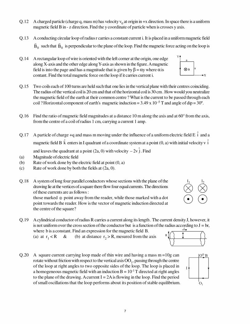
Q.12 A charged particle (charge q, mass m) has velocity v0 at origin in +x direction. In space there is a uniform
magnetic field B in - z direction. Find the y coordinate of particle when is crosses y axis.
Q.13 A conducting circular loop of radius r carries a constant current i. It is placed in a uniform magnetic field
0B
such that 0B
is perpendicular to the plane of the loop. Find the magnetic force acting on the loop is
Q.14 A rectangular loop of wire is oriented with the left corner at the origin, one edge
along X-axis and the other edge along Y-axis as shown in the figure. A magnetic
field is into the page and has a magnitude that is given by β = αy where α is
contant. Find the total magnetic force on the loop if it carries current i.
Q.15 Two coils each of 100 turns are held such that one lies in the vertical plane with their centres coinciding.
The radius of the vertical coil is 20 cm and that of the horizontal coil is 30 cm . How would you neutralize
the magnetic field of the earth at their common centre ? What is the current to be passed through each
coil ? Horizontal component of earth's magnetic induction = 3.49 x 10 -5 T and angle of dip = 30º.
Q.16 Find the ratio of magnetic field magnitudes at a distance 10 m along the axis and at 60° from the axis,
from the centre of a coil of radius 1 cm, carrying a current 1 amp.
Q.17 A particle of charge +q and mass m moving under the influence of a uniform electric field E i and a
magnetic field B k enters in I quadrant of a coordinate system at a point (0, a) with initial velocity v i
and leaves the quadrant at a point (2a, 0) with velocity – 2v j . Find
(a) Magnitude of electric field
(b) Rate of work done by the electric field at point (0, a)
(c) Rate of work done by both the fields at (2a, 0).
Q.18 A system of long four parallel conductors whose sections with the plane of the
drawing lie at the vertices of a square there flow four equal currents. The directions
of these currents are as follows :
those marked ⊗ point away from the reader, while those marked with a dot
point towards the reader. How is the vector of magnetic induction directed at
the centre of the square?
Q.19 A cylindrical conductor of radius R carries a current along its length . The current density J, however, it
is not uniform over the cross section of the conductor but is a function of the radius according to J = br,
where b is a constant. Find an expression for the magnetic field B.
(a) at r1 < R & (b) at distance r
2 > R, mesured from the axis
Q.20 A square current carrying loop made of thin wire and having a mass m =10g can
rotate without friction with respect to the vertical axis OO1, passing through the centre
of the loop at right angles to two opposite sides of the loop. The loop is placed in
a homogeneous magnetic field with an induction B = 10-1 T directed at right angles
to the plane of the drawing. A current I = 2A is flowing in the loop. Find the period
of small oscillations that the loop performs about its position of stable equilibrium.
7
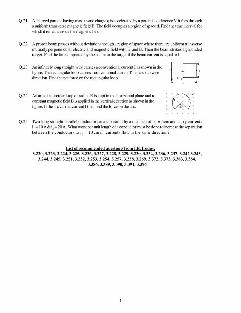
Q.21 A charged particle having mass m and charge q is accelerated by a potential difference V, it flies through
a uniform transverse magnetic field B. The field occupies a region of space d. Find the time interval for
which it remains inside the magnetic field.
Q.22 A proton beam passes without deviation through a region of space where there are uniform transverse
mutually perpendicular electric and magnetic field with E and B. Then the beam strikes a grounded
target. Find the force imparted by the beam on the target if the beam current is equal to I.
Q.23 An infinitely long straight wire carries a conventional current I as shown in the
figure. The rectangular loop carries a conventional current I' in the clockwise
direction. Find the net force on the rectangular loop.
Q.24 An arc of a circular loop of radius R is kept in the horizontal plane and a
constant magnetic field B is applied in the vertical direction as shown in the
figure. If the arc carries current I then find the force on the arc.
Q.25 Two long straight parallel conductors are separated by a distance of r1 = 5cm and carry currents
i1 = 10 A & i
2 = 20 A . What work per unit length of a conductor must be done to increase the separation
between the conductors to r2 = 10 cm if , currents flow in the same direction?
List of recommended questions from I.E. Irodov.
3.220, 3.223, 3.224, 3.225, 3.226, 3.227, 3.228, 3.229, 3.230, 3.234, 3.236, 3.237, 3.242 3.243,
3.244, 3.245, 3.251, 3.252, 3.253, 3.254, 3.257, 3.258, 3.269, 3.372, 3.373, 3.383, 3.384,
3.386, 3.389, 3.390, 3.391, 3.396
8
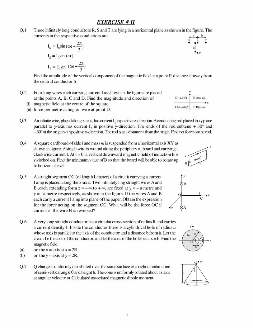
EXERCISE # II
Q.1 Three infinitely long conductors R, S and T are lying in a horizontal plane as shown in the figure. The
currents in the respective conductors are
IR = I
0sin )
3
2t(
π+ω
IS = I
0sin (ωt)
IT = I
0sin )
3
2t(
π−ω
Find the amplitude of the vertical component of the magnetic field at a point P, distance 'a' away from
the central conductor S.
Q.2 Four long wires each carrying current I as shown in the figure are placed
at the points A, B, C and D. Find the magnitude and direction of
(i) magnetic field at the centre of the square.
(ii) force per metre acting on wire at point D.
Q.3 An infinite wire, placed along z-axis, has current I1 in positive z-direction. A conducting rod placed in xy plane
parallel to y-axis has current I2 in positive y-direction. The ends of the rod subtend + 30° and
– 60° at the origin with positive x-direction. The rod is at a distance a from the origin. Find net force on the rod.
Q.4 A square cardboard of side l and mass m is suspended from a horizontal axis XY as
shown in figure. A single wire is wound along the periphery of board and carrying a
clockwise current I. At t = 0, a vertical downward magnetic field of induction B is
switched on. Find the minimum value of B so that the board will be able to rotate up
to horizontal level.
Q.5 A straight segment OC (of length L meter) of a circuit carrying a current
I amp is placed along the x-axis. Two infinitely ling straight wires A and
B ,each extending form z = – ∞ to + ∞, are fixed at y = – a metre and
y = +a metre respectively, as shown in the figure. If the wires A and B
each carry a current I amp into plane of the paper. Obtain the expression
for the force acting on the segment OC. What will be the force OC if
current in the wire B is reversed?
Q.6 A very long straight conductor has a circular cross-section of radius R and carries
a current density J. Inside the conductor there is a cylindrical hole of radius a
whose axis is parallel to the axis of the conductor and a distance b from it. Let the
z-axis be the axis of the conductor, and let the axis of the hole be at x = b. Find the
magnetic field
(a) on the x = axis at x = 2R
(b) on the y = axis at y = 2R.
Q.7 Q charge is uniformly distributed over the same surface of a right circular cone
of semi-vertical angle θ and height h. The cone is uniformly rotated about its axis
at angular velocity ω. Calculated associated magnetic dipole moment.
9

FR
EE
Dow
nlo
ad
Stu
dy
Pa
cka
ge
from
web
site
:
ww
w.t
ekocla
sses
.com
Page
10 o
f 20 M
AG
NE
TIC
EF
FE
CT
S O
F C
UR
RE
NT
Q.8 A wire loop carrying current I is placed in the X-Y plane as shown
in the figure
(a) If a particle with charge +Q and mass m is placed at the centre P
and given a velocity along NP (fig). Find its instantaneous acceleration
(b) If an external uniform magnetic induction field B = B i is applied,
find the torque acting on the loop due to the field.
Q.9 A long straight wire carries a current of 10 A directed along the negative
y-axis as shown in figure. A uniform magnetic field B0 of magnitude 10−6 T
is directed parallel to the x-axis. What is the resultant magnetic field at the
following points?
(a) x = 0 , z = 2 m ; (b) x = 2 m, z = 0 ; (c) x = 0 , z = − 0.5 m
Q.10 A stationary, circular wall clock has a face with a radius of 15cm. Six turns of wire are wound around
its perimeter, the wire carries a current 2.0 A in the clockwise direction. The clock is located, where
there is a constant , uniform external magnetic field of 70 mT (but the clock still keeps perfect time)
at exactly 1:00 pm, the hour hand of the clock points in the direction of the external magnetic field
(a) After how many minutes will the minute hand point in the direction of the torque on the winding due
to the magnetic field ?
(b) What is the magnitude of this torque.
Q.11 A U-shaped wire of mass m and length l is immersed with its two ends
in mercury (see figure). The wire is in a homogeneous field of magnetic
induction B. If a charge, that is, a current pulse q = ∫ dti , is sent through
the wire, the wire will jump up.
Calculate, from the height h that the wire reaches, the size of the charge or current pulse, assuming
that the time of the current pulse is very small in comparision with the time of flight. Make use of the
fact that impulse of force equals Fdt∫ ,which equals mv. Evaluate q for B = 0.1 Wb/m2, m = 10gm,
= 20cm & h = 3 meters.[g = 10 m/s2]
Q.12 A current i, indicated by the crosses in fig. is established in a strip of copper
of height h and width w. A uniform field of magnetic induction B is applied
at right angles to the strip.
(a) Calculate the drift speed vd for the electrons.
(b) What are the magnitude and dirction of the magnetic force F acting on the
electrons?
(c) What would the magnitude & direction of homogeneous electric field E have
to be in order to counter balance the effect of the magnetic field ?
(d) What is the voltage V necessary between two sides of the conductor in order to create this field E?
Between which sides of the conductor would this voltage have to be applied ?
(e) If no electric field is applied form the outside the electrons will be pushed somewhat to one side &
thereforce will give rise to a uniform electric field EH across the conductor untill the force of this electrostatic
field EH balanace the magnetic forces encountered in part (b) . What will be the magnitude and direction
of the field EH? Assume that n, the number of conduction electrons per unit volume, is 1.1x1029/m3
& that h = 0.02 meter , w = 0.1cm , i = 50 amp , & B = 2 webers/meter2.
10
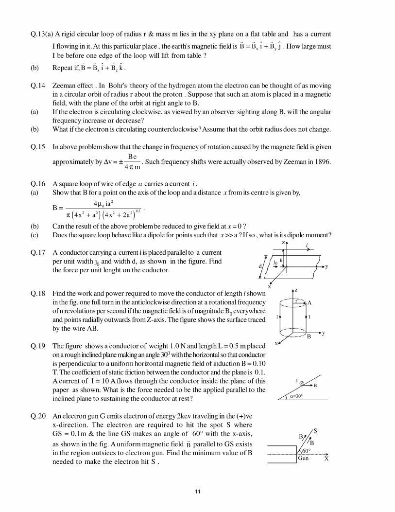
Q.13(a) A rigid circular loop of radius r & mass m lies in the xy plane on a flat table and has a current
I flowing in it. At this particular place , the earth's magnetic field is B B i B jx y= + . How large must
I be before one edge of the loop will lift from table ?
(b) Repeat if, B B i B kx z= + .
Q.14 Zeeman effect . In Bohr's theory of the hydrogen atom the electron can be thought of as moving
in a circular orbit of radius r about the proton . Suppose that such an atom is placed in a magnetic
field, with the plane of the orbit at right angle to B.
(a) If the electron is circulating clockwise, as viewed by an observer sighting along B, will the angular
frequency increase or decrease?
(b) What if the electron is circulating counterclockwise? Assume that the orbit radius does not change.
Q.15 In above problem show that the change in frequency of rotation caused by the magnete field is given
approximately by ∆v = ±Be
m4 π. Such frequency shifts were actually observed by Zeeman in 1896.
Q.16 A square loop of wire of edge a carries a current i .
(a) Show that B for a point on the axis of the loop and a distance x from its centre is given by,
B = ( ) ( )
4
4 4 2
0
2
2 2 2 21/2
µ
π
ia
x a x a+ +.
(b) Can the result of the above problem be reduced to give field at x = 0 ?
(c) Does the square loop behave like a dipole for points such that x >> a ? If so , what is its dipole moment?
Q.17 A conductor carrying a current i is placed parallel to a current
per unit width j0 and width d, as shown in the figure. Find
the force per unit lenght on the coductor.
Q.18 Find the work and power required to move the conductor of length l shown
in the fig. one full turn in the anticlockwise direction at a rotational frequency
of n revolutions per second if the magnetic field is of magnitude B0 everywhere
and points radially outwards from Z-axis. The figure shows the surface traced
by the wire AB.
Q.19 The figure shows a conductor of weight 1.0 N and length L = 0.5 m placed
on a rough inclined plane making an angle 300 with the horizontal so that conductor
is perpendicular to a uniform horizontal magnetic field of induction B = 0.10
T. The coefficient of static friction between the conductor and the plane is 0.1.
A current of I = 10 A flows through the conductor inside the plane of this
paper as shown. What is the force needed to be the applied parallel to the
inclined plane to sustaining the conductor at rest?
Q.20 An electron gun G emits electron of energy 2kev traveling in the (+)ve
x-direction. The electron are required to hit the spot S where
GS = 0.1m & the line GS makes an angle of 60° with the x-axis,
as shown in the fig. A uniform magnetic field B parallel to GS exists
in the region outsiees to electron gun. Find the minimum value of B
needed to make the electron hit S .
11
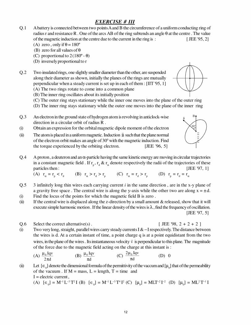
EXERCISE # IIIQ.1 A battery is connected between two points A and B the circumference of a uniform conducting ring of
radius r and resistance R . One of the arcs AB of the ring subtends an angle θ at the centre . The value
of the magnetic induction at the centre due to the current in the ring is : [ JEE '95, 2]
(A) zero , only if θ = 180º (B) zero for all values of θ(C) proportional to 2 (180º - θ)
(D) inversely proportional to r
Q.2 Two insulated rings, one slightly smaller diameter than the other, are suspended
along their diameter as shown, initially the planes of the rings are mutually
perpendicular when a steady current is set up in each of them : [IIT '95, 1]
(A) The two rings rotate to come into a common plane
(B) The inner ring oscillates about its initially position
(C) The outer ring stays stationary while the inner one moves into the plane of the outer ring
(D) The inner ring stays stationary while the outer one moves into the plane of the inner ring
Q.3 An electron in the ground state of hydrogen atom is revolving in anticlock-wise
direction in a circular orbit of radius R .
(i) Obtain an expression for the orbital magnetic dipole moment of the electron
(ii) The atom is placed in a uniform magnetic. Induction B such that the plane normal
of the electron orbit makes an angle of 300 with the magnetic induction. Find
the torque experienced by the orbiting electron. [JEE '96, 5]
Q.4 A proton , a deuteron and an α-particle having the same kinetic energy are moving in circular trajectories
in a constant magnetic field . If rp , r
d & r
α denote respectively the radii of the trajectories of these
particles then : [JEE '97, 1]
(A) rα = r
p < r
d(B) r
α > r
d > r
p(C) r
α = r
d > r
p(D) r
p = r
d = r
α
Q.5 3 infinitely long thin wires each carrying current i in the same direction , are in the x-y plane of
a gravity free space . The central wire is along the y-axis while the other two are along x = ± d.
(i) Find the locus of the points for which the magnetic field B is zero .
(ii) If the central wire is displaced along the z-direction by a small amount & released, show that it will
execute simple harmonic motion . If the linear density of the wires is λ , find the frequency of oscillation.
[JEE '97, 5]
Q.6 Select the correct alternative(s) . [ JEE '98, 2 + 2 + 2 ]
(i) Two very long, straight, parallel wires carry steady currents I & − I respectively. The distance between
the wires is d. At a certain instant of time, a point charge q is at a point equidistant from the two
wires, in the plane of the wires . Its instantaneous velocity v is perpendicular to this plane. The magnitude
of the force due to the magnetic field acting on the charge at this instant is :
(A) µ
π0
2
Iqv
d(B)
µπ0 Iqv
d(C)
2 0µ
π
Iqv
d(D) 0
(ii) Let [∈0] denote the dimensional formula of the permittivity of the vaccum and [µ
0] that of the permeability
of the vacuum . If M = mass, L = length, T = time and
I = electric current ,
(A) [∈0] = M−1 L−3 T2 I (B) [∈
0] = M−1 L−3 T4 I2 (C) [µ
0] = MLT−2 I−2 (D) [µ
0] = ML2 T−1 I
12
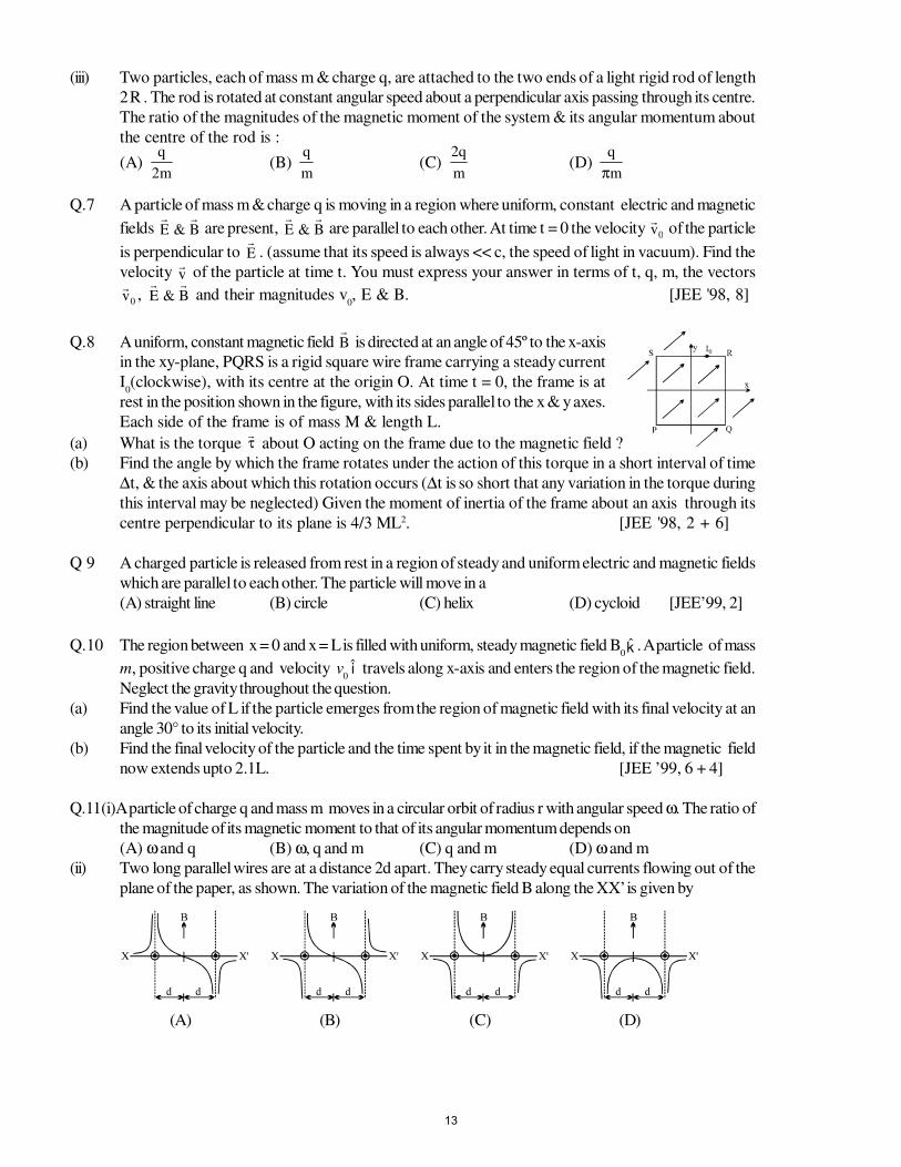
(iii) Two particles, each of mass m & charge q, are attached to the two ends of a light rigid rod of length
2 R . The rod is rotated at constant angular speed about a perpendicular axis passing through its centre.
The ratio of the magnitudes of the magnetic moment of the system & its angular momentum about
the centre of the rod is :
(A) q
m2(B)
q
m(C)
2q
m(D)
q
mπ
Q.7 A particle of mass m & charge q is moving in a region where uniform, constant electric and magnetic
fields E B& are present,
E B& are parallel to each other. At time t = 0 the velocity
v0
of the particle
is perpendicular to E . (assume that its speed is always << c, the speed of light in vacuum). Find the
velocity v of the particle at time t. You must express your answer in terms of t, q, m, the vectors
v0
, E B& and their magnitudes v
0, E & B. [JEE '98, 8]
Q.8 A uniform, constant magnetic field B is directed at an angle of 45º to the x-axis
in the xy-plane, PQRS is a rigid square wire frame carrying a steady current
I0(clockwise), with its centre at the origin O. At time t = 0, the frame is at
rest in the position shown in the figure, with its sides parallel to the x & y axes.
Each side of the frame is of mass M & length L.
(a) What is the torque τ about O acting on the frame due to the magnetic field ?
(b) Find the angle by which the frame rotates under the action of this torque in a short interval of time
∆t, & the axis about which this rotation occurs (∆t is so short that any variation in the torque during
this interval may be neglected) Given the moment of inertia of the frame about an axis through its
centre perpendicular to its plane is 4/3 ML2. [JEE '98, 2 + 6]
Q 9 A charged particle is released from rest in a region of steady and uniform electric and magnetic fields
which are parallel to each other. The particle will move in a
(A) straight line (B) circle (C) helix (D) cycloid [JEE’99, 2]
Q.10 The region between x = 0 and x = L is filled with uniform, steady magnetic field B0k . A particle of mass
m, positive charge q and velocity v0i travels along x-axis and enters the region of the magnetic field.
Neglect the gravity throughout the question.
(a) Find the value of L if the particle emerges from the region of magnetic field with its final velocity at an
angle 30° to its initial velocity.
(b) Find the final velocity of the particle and the time spent by it in the magnetic field, if the magnetic field
now extends upto 2.1L. [JEE ’99, 6 + 4]
Q.11(i)A particle of charge q and mass m moves in a circular orbit of radius r with angular speed ω. The ratio of
the magnitude of its magnetic moment to that of its angular momentum depends on
(A) ω and q (B) ω, q and m (C) q and m (D) ω and m
(ii) Two long parallel wires are at a distance 2d apart. They carry steady equal currents flowing out of the
plane of the paper, as shown. The variation of the magnetic field B along the XX’ is given by
(A) (B) (C) (D)
13
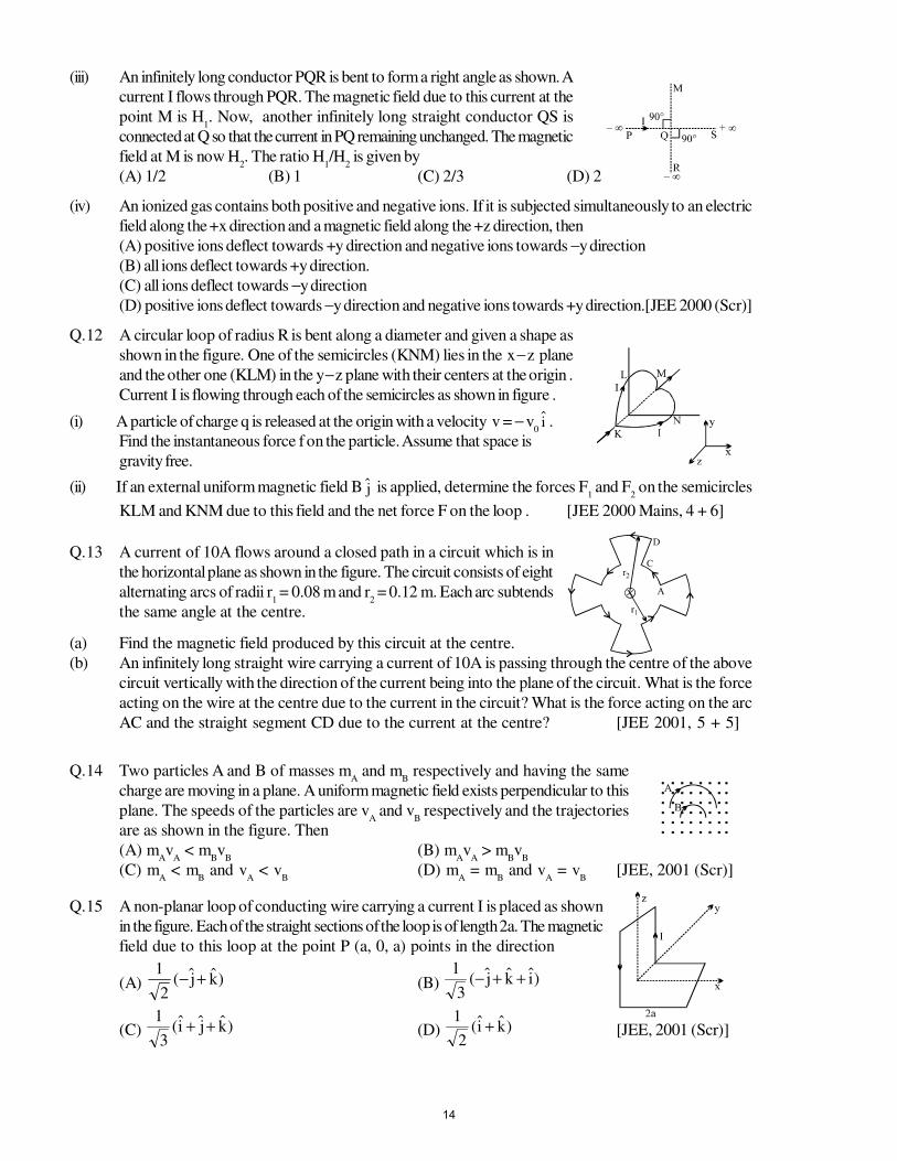
(iii) An infinitely long conductor PQR is bent to form a right angle as shown. A
current I flows through PQR. The magnetic field due to this current at the
point M is H1. Now, another infinitely long straight conductor QS is
connected at Q so that the current in PQ remaining unchanged. The magnetic
field at M is now H2. The ratio H
1/H
2 is given by
(A) 1/2 (B) 1 (C) 2/3 (D) 2
(iv) An ionized gas contains both positive and negative ions. If it is subjected simultaneously to an electric
field along the +x direction and a magnetic field along the +z direction, then
(A) positive ions deflect towards +y direction and negative ions towards −y direction
(B) all ions deflect towards +y direction.
(C) all ions deflect towards −y direction
(D) positive ions deflect towards −y direction and negative ions towards +y direction.[JEE 2000 (Scr)]
Q.12 A circular loop of radius R is bent along a diameter and given a shape as
shown in the figure. One of the semicircles (KNM) lies in the x − z plane
and the other one (KLM) in the y − z plane with their centers at the origin .
Current I is flowing through each of the semicircles as shown in figure .
(i) A particle of charge q is released at the origin with a velocity v = − v0i .
Find the instantaneous force f on the particle. Assume that space is
gravity free.
(ii) If an external uniform magnetic field B j is applied, determine the forces F1 and F
2 on the semicircles
KLM and KNM due to this field and the net force F on the loop . [JEE 2000 Mains, 4 + 6]
Q.13 A current of 10A flows around a closed path in a circuit which is in
the horizontal plane as shown in the figure. The circuit consists of eight
alternating arcs of radii r1 = 0.08 m and r
2 = 0.12 m. Each arc subtends
the same angle at the centre.
(a) Find the magnetic field produced by this circuit at the centre.
(b) An infinitely long straight wire carrying a current of 10A is passing through the centre of the above
circuit vertically with the direction of the current being into the plane of the circuit. What is the force
acting on the wire at the centre due to the current in the circuit? What is the force acting on the arc
AC and the straight segment CD due to the current at the centre? [JEE 2001, 5 + 5]
Q.14 Two particles A and B of masses mA and m
B respectively and having the same
charge are moving in a plane. A uniform magnetic field exists perpendicular to this
plane. The speeds of the particles are vA and v
B respectively and the trajectories
are as shown in the figure. Then
(A) mAv
A < m
Bv
B(B) m
Av
A > m
Bv
B
(C) mA < m
B and v
A < v
B(D) m
A = m
B and v
A = v
B[JEE, 2001 (Scr)]
Q.15 A non-planar loop of conducting wire carrying a current I is placed as shown
in the figure. Each of the straight sections of the loop is of length 2a. The magnetic
field due to this loop at the point P (a, 0, a) points in the direction
(A) )kj(2
1+− (B) )ikj(
3
1++−
(C) )kji(3
1++ (D) )ki(
2
1+ [JEE, 2001 (Scr)]
14
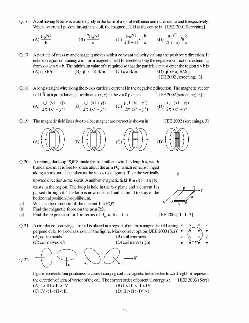
Q.16 A coil having N turns is wound tightly in the form of a spiral with inner and outer radii a and b respectively.
When a current I passes through the coil, the magnetic field at the centre is [JEE, 2001 Screening]
(A) b
NI0
µ (B)
a
NI20
µ(C)
a
bn
)ab(2
NI0 l−
µ(D)
a
bn
)ab(2
IN0 l−
µ
Q.17 A particle of mass m and charge q moves with a constant velocity v along the positive x direction. It
enters a region containing a uniform magnetic field B directed along the negative z direction, extending
from x = a to x = b. The minimum value of v required so that the particle can just enter the region x > b is
(A) q b B/m (B) q( b – a) B/m (C) q a B/m (D) q(b + a) B/2m
[JEE 2002 (screening), 3]
Q.18 A long straight wire along the z-axis carries a current I in the negative z direction. The magnetic vector
field B at a point having coordinates (x, y) in the z = 0 plane is [JEE 2002 (screening), 3]
(A) µ
π0
2 22
I yi xj
x y
( )
( )
−+
(B) µ
π0
2 22
I xi yj
x y
( )
( )
++
(C) µ
π0
2 22
I xj yi
x y
( )
( )
−+
(D)µ
π0
2 22
I xi yj
x y
( )
( )
−+
Q.19 The magnetic field lines due to a bar magnet are correctly shown in [JEE 2002 (screening), 3]
(A) (B) (C) (D)
Q.20 A rectangular loop PQRS made from a uniform wire has length a, width
b and mass m. It is free to rotate about the arm PQ, which remains hinged
along a horizontal line taken as the y-axis (see figure). Take the vertically
upward direction as the z-axis. A uniform magnetic field B i k B= +( )3 4 0
exists in the region. The loop is held in the x-y plane and a current I is
passed through it. The loop is now released and is found to stay in the
horizontal position in equilibrium.
(a) What is the direction of the current I in PQ?
(b) Find the magnetic force on the arm RS.
(c) Find the expression for I in terms of B0, a, b and m. [JEE 2002, 1+1+3]
Q.21 A circular coil carrying current I is placed in a region of uniform magnetic field acting
perpendicular to a coil as shown in the figure. Mark correct option [JEE 2003 (Scr)]
(A) coil expands (B) coil contracts
(C) coil moves left (D) coil moves right
Q.22
Figure represents four positions of a current carrying coil is a magnetic field directed towards right. n represent
the direction of area of vector of the coil. The correct order of potential energy is : [JEE 2003 (Scr)]
(A) I > III > II > IV (B) I < III < II < IV
(C) IV < I < II < II (D) II > II > IV > I
15
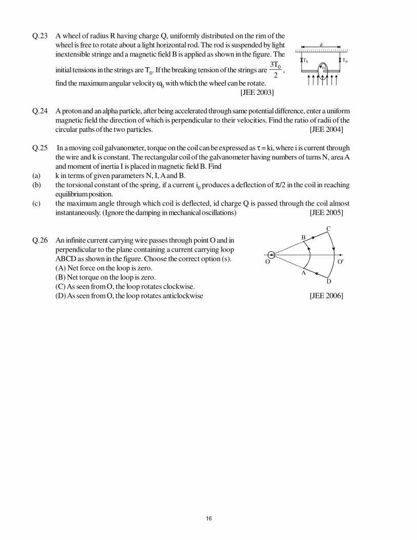
Q.23 A wheel of radius R having charge Q, uniformly distributed on the rim of the
wheel is free to rotate about a light horizontal rod. The rod is suspended by light
inextensible stringe and a magnetic field B is applied as shown in the figure. The
initial tensions in the strings are T0. If the breaking tension of the strings are
2
T3 0,
find the maximum angular velocity ω0 with which the wheel can be rotate.
[JEE 2003]
Q.24 A proton and an alpha particle, after being accelerated through same potential difference, enter a uniform
magnetic field the direction of which is perpendicular to their velocities. Find the ratio of radii of the
circular paths of the two particles. [JEE 2004]
Q.25 In a moving coil galvanometer, torque on the coil can be expressed as τ = ki, where i is current through
the wire and k is constant. The rectangular coil of the galvanometer having numbers of turns N, area A
and moment of inertia I is placed in magnetic field B. Find
(a) k in terms of given parameters N, I, A and B.
(b) the torsional constant of the spring, if a current i0 produces a deflection of π/2 in the coil in reaching
equilibrium position.
(c) the maximum angle through which coil is deflected, id charge Q is passed through the coil almost
instantaneously. (Ignore the damping in mechanical oscillations) [JEE 2005]
Q.26 An infinite current carrying wire passes through point O and in
perpendicular to the plane containing a current carrying loop
ABCD as shown in the figure. Choose the correct option (s).
(A) Net force on the loop is zero.
(B) Net torque on the loop is zero.
(C) As seen from O, the loop rotates clockwise.
(D) As seen from O, the loop rotates anticlockwise [JEE 2006]
16
ANSWER KEYEXERCISE # I
Q.1l
i
πµ
8
2 0Q.2
22
54π × 10–5 T Q.3
a
)122(0
π
µ− i
Q.4 zero Q.5
π+
µj
1k
4
3
R4
I0Q.6
+ππ
µ1
2
3
r4
i0
Q.7 B = ( )µ
ππ π0 2
42 2 2 1
i
R− + Q.8 (i) 1.3 ×10⁻⁴T, (ii) zero Q.9 µ
0 weber.m–1
Q.10µ
π0iqv
2 aQ.11 k10 Q.12
qB
mv2 0Q.13 zero
Q.14 F = αa2i j Q.15 i1 = 0.1110 A, i
2 = 0.096 A Q.16 74
Q.17 (a) 3
4
2mv
qa, (b)
3
4
3mv
a, (c) zero Q.18 In the plane of the drawing from right to left
Q.19 B1 =
3
br210
µ, B
2 =
2
30
r3
RbµQ.20 T
0
= 26
πm
IB = 0.57 s
Q.21 t = Bq
mα
, where α = sin–1
mV2
qdB
Q.22Be
IEmQ.23
−π
′µb
1
a
1
2
CII0 to the left
Q.24 2 I R B Q.251
2210
r
rn
2
IIW
π
µ= = 27.6 µ J/m
EXERCISE # II
Q.1)ba(
b3
2
I22
00
+πµ
Q.2 (i)
π
µ
a
I4
4
0 along Y-axis,
(ii) 10a2
I
4
20
π
µ, π+
3
1tan4
with positive axis
17
Q.3π
µ4
II 210 ln (3) along – ve z direction Q.4
lI2
gm
Q.5 F = µ
π0
2 2 2
22I
nL a
a
+
( )k− , zero
Q.6 (a) B =
−
−
µ
2
R
bR2
a
2
J 20
, (b) Bx =
+−µ
22
2
0bR4
a
4
1RJ , B
y =
+
µ−
22
20
bR4
ba
2
J
Q.7 θω 22 tanh4
QQ.8 (a)
−
πµ
133
a6
I
m
VQ 0, (b) ja
4
3
3IB 2
−
π=τ
Q.9 (a) 0 (b) 1.41 × 10 –6 T , 45º in xz - plane, (c) 5 × 10 –6 T , + x - direction]
Q.10 (a) 20 min. (b) 5.94 x 10⁻² Nm
Q.11 15 C
Q.12 (a) 1.4 x 10⁻⁴ m/s (b) 4.5 x 10⁻²³ N (down) (c) 2.8 x 10⁻⁴ V/m (down)
(d) 5.7 x 10⁻⁶ V (top + , bottom −) (e) same as (c)
Q.13 (a) I =
( )mg
r B Bx yπ 2 21 2
+/ (b) I = mg
rBxπQ.14 (a) increase, (b) decrease
Q.17 )k(h2
dtan
Ji 100 −
π
µ −Q.18 − 2 π r B
0 i l , − 2 π r B
0 i l n
Q.19 0.62 N < F < 0.88 N Q.20 Bmin
= 4.7×10⁻³ T
EXERCISE # III
Q.1 B Q.2 A Q.3 (i) m = m4
he
π ; m8
Bhe
π=τ
Q.4 A
Q.5 z = 0 , x = ±
3
d, (ii)
I
d20
πµπ λ
Q.6 (i) D (ii) B, C (iii) A
Q.7 v
= m
qE
t + 0v
cos ωt + [v0 sin ωt] k , where ω =
m
qB; k = (
v0 x E
)/v0 x E
Q.8 (a) τ =
2
LIB 20 ( )ji − (b) θ =
3
4 M
BI0 ∆t2 Q.9 A
18

Q.10 (a) 0
0
qB2
mv (b)velocity=-v, time=
0qB
mπ Q.11 (i) C (ii) B (iii) C (iv) C
Q.12 (i) −R4
I0µq v
0 k (ii) F
1 = 2 I R B F
2 =2 I R B , Net force = F
1 + F
2 = 4 I R B i
Q.13 (a) 6.6 × 10⁻⁵T, (b) 0, 0, 8 × 10⁻⁶Nt
Q.14 B Q.15 D Q.16 C Q.17 B Q.18 A Q.19 D
Q.20 (a) current in loop PQRS is clockwise from P to QRS., (b) F
= BI0b )i4k3( − , (c) I =
0bB6
mg
Q.21 A Q.22 A Q.23 ω =BQR
Td2
0Q.24
2
1
q
q.
m
m
r
r
p
pp == α
αα
Q.25 (a) k = NAB, (b) C = π
NABi20
, (c) Q × 0
li2
NABπQ.26 A,C
19
STUDY PACKAGE
Target: IIT-JEE (Advanced)
SUBJECT: PHYSICS
TOPIC: XII P6. Electromagnetic Induction and Alternating Current
Index:
1. Key Concepts
2. Exercise I
3. Exercise II
4. Exercise III
5. Exercise IV
6. Answer Key
7. 34 Yrs. Que. from IIT-JEE
8. 10 Yrs. Que. from AIEEE
1
Page
2 o
f 16 E
.M.I
. & A
.C.
KEY CONCEPTS
When a conductor is moved across a magnetic field, an electromotive force (emf) is produced in the
conductor. If the conductors forms part of a closed circuit then the emf produced caused an electric
current to flow round the circuit. Hence an emf (and thus a current) is induced in the conductor as a result
of its movement across the magnetic field. This is known as "ELECTROMAGNETIC INDUCTION."
1. MAGNETIC FLUX :
φ = B . A = BA cos θ weber for uniform B
.
φ = ∫B . dA for non uniform B
.
2. FARADAY'S LAWS OF ELECTROMAGNETIC INDUCTION :
(i) An induced emf is setup whenever the magnetic flux linking that circuit changes.
(ii) The magnitude of the induced emf in any circuit is proportional to the rate of change of the magnetic
flux linking the circuit, ε α dt
dφ .
3. LENZ'S LAWS :
The direction of an induced emf is always such as to oppose the cause producing it .
4. LAW OF EMI :
e = − dt
dφ. The negative sign indicated that the induced emf opposes the change of the flux .
5. EMF INDUCED IN A STRAIGHT CONDUCTOR IN UNIFORM MAGNETIC FIELD :
E = BLV sin θ voltwhereB = flux density in wb/m2 ; L = length of the conductor (m) ;
V = velocity of the conductor (m/s) ;
θ = angle between direction of motion of conductor & B .
6. COIL ROTATION IN MAGNETIC FIELD SUCH THAT AXIS OF ROTATION IS PERPENDICULAR TO
THE MAGNETIC FIELD :
Instantaneous induced emf . E = NABω sin ωt = E0 sin ωt , where
N = number of turns in the coil ; A = area of one turn ;
B = magnetic induction ; ω = uniform angular velocity of the coil ;E0 = maximum induced emf .
7. SELF INDUCTION & SELF INDUCTANCE :
When a current flowing through a coil is changed the flux linking with its own winding changes & due to
the change in linking flux with the coil an emf is induced which is known as self induced emf & this
phenomenon is known as self induction . This induced emf opposes the causes of Induction. The property
of the coil or the circuit due to which it opposes any change of the current coil or the circuit is known as
SELF & INDUCTANCE . It's unit is Henry .
Coefficient of Self inductance L = i
sφor φs = Li
2
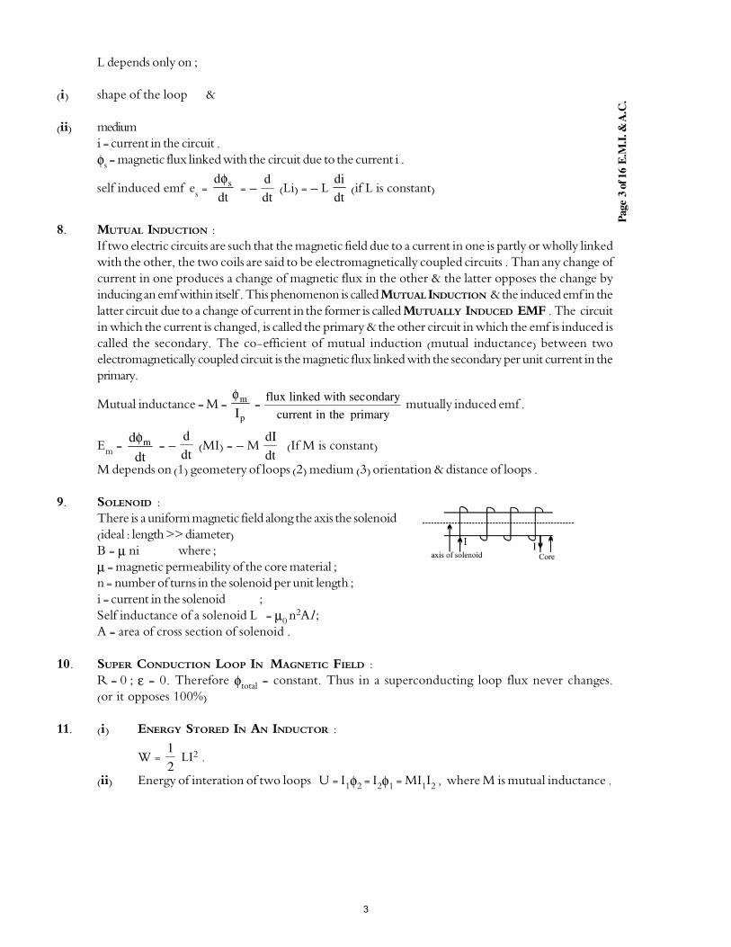
Page
3 o
f 16 E
.M.I
. & A
.C.
L depends only on ;
(i) shape of the loop &
(ii) medium
i = current in the circuit .
φs = magnetic flux linked with the circuit due to the current i .
self induced emf es =
dt
d sφ = −
dt
d (Li) = − L
dt
di (if L is constant)
8. MUTUAL INDUCTION :
If two electric circuits are such that the magnetic field due to a current in one is partly or wholly linked
with the other, the two coils are said to be electromagnetically coupled circuits . Than any change of
current in one produces a change of magnetic flux in the other & the latter opposes the change by
inducing an emf within itself . This phenomenon is called MUTUAL INDUCTION & the induced emf in the
latter circuit due to a change of current in the former is called MUTUALLY INDUCED EMF . The circuit
in which the current is changed, is called the primary & the other circuit in which the emf is induced is
called the secondary. The co0efficient of mutual induction (mutual inductance) between two
electromagnetically coupled circuit is the magnetic flux linked with the secondary per unit current in the
primary.
Mutual inductance = M = p
m
I
φ =
flux linked with ondary
current in the primary
sec mutually induced emf .
Em = dt
d mφ = −
dt
d (MI) = − M
dt
dI (If M is constant)
M depends on (1) geometery of loops (2) medium (3) orientation & distance of loops .
9. SOLENOID :
There is a uniform magnetic field along the axis the solenoid
(ideal : length >> diameter)
B = µ ni where ;
µ = magnetic permeability of the core material ;n = number of turns in the solenoid per unit length ;
i = current in the solenoid ;
Self inductance of a solenoid L = µ0 n2Al ;
A = area of cross section of solenoid .
10. SUPER CONDUCTION LOOP IN MAGNETIC FIELD :
R = 0 ; ε = 0. Therefore φtotal = constant. Thus in a superconducting loop flux never changes.(or it opposes 100%)
11. (i) ENERGY STORED IN AN INDUCTOR :
W = 2
1 LI2 .
(ii) Energy of interation of two loops U = I1φ2 = I2φ1 = MI1I2 , where M is mutual inductance .
3
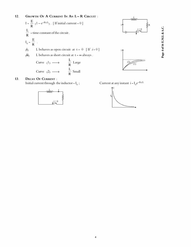
Page
4 o
f 16 E
.M.I
. & A
.C.
12. GROWTH OF A CURRENT IN AN L −−−− R CIRCUIT :
I = R
E (1 − e−Rt/L) . [ If initial current = 0 ]
R
L = time constant of the circuit .
I0 = R
E .
(i) L behaves as open circuit at t = 0 [ If i = 0 ]
(ii) L behaves as short circuit at t = ∞ always .
Curve (1) →R
L Large
Curve (2) →R
L Small
13. DECAY OF CURRENT :
Initial current through the inductor = I0 ; Current at any instant i = I0e−Rt/L
4
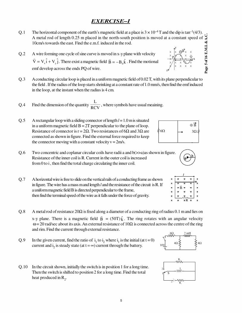
Page
5 o
f 16 E
.M.I
. & A
.C.
EXERCISE–I
Q.1 The horizontal component of the earth’s magnetic field at a place is 3 × 10⁻⁴ T and the dip is tan–1(4/3).
A metal rod of length 0.25 m placed in the north-south position is moved at a constant speed of
10cm/s towards the east. Find the e.m.f. induced in the rod.
Q.2 A wire forming one cycle of sine curve is moved in x-y plane with velocityV V i V jx y= + . There exist a magnetic field
B B k= − 0
. Find the motional
emf develop across the ends PQ of wire.
Q.3 A conducting circular loop is placed in a uniform magnetic field of 0.02 T, with its plane perpendicular to
the field . If the radius of the loop starts shrinking at a constant rate of 1.0 mm/s, then find the emf induced
in the loop, at the instant when the radius is 4 cm.
Q.4 Find the dimension of the quantity RCV
L, where symbols have usual meaining.
Q.5 A rectangular loop with a sliding connector of length l = 1.0 m is situated
in a uniform magnetic field B = 2T perpendicular to the plane of loop.
Resistance of connector is r = 2Ω. Two resistances of 6Ω and 3Ω are
connected as shown in figure. Find the external force required to keep
the connector moving with a constant velocity v = 2m/s.
Q.6 Two concentric and coplanar circular coils have radii a and b(>>a)as shown in figure.
Resistance of the inner coil is R. Current in the outer coil is increased
from 0 to i , then find the total charge circulating the inner coil.
Q.7 A horizontal wire is free to slide on the vertical rails of a conducting frame as shown
in figure. The wire has a mass m and length l and the resistance of the circuit is R. If
a uniform magnetic field B is directed perpendicular to the frame,
then find the terminal speed of the wire as it falls under the force of gravity.
Q.8 A metal rod of resistance 20Ω is fixed along a diameter of a conducting ring of radius 0.1 m and lies on
x-y plane. There is a magnetic field B
= (50T) k . The ring rotates with an angular velocity
ω = 20 rad/sec about its axis. An external resistance of 10Ω is connected across the centre of the ring
and rim. Find the current through external resistance.
Q.9 In the given current, find the ratio of i1 to i
2 where i
1 is the initial (at t = 0)
current and i2 is steady state (at t = ∞) current through the battery.
Q.10 In the circuit shown, initially the switch is in position 1 for a long time.
Then the switch is shifted to position 2 for a long time. Find the total
heat produced in R2.
5
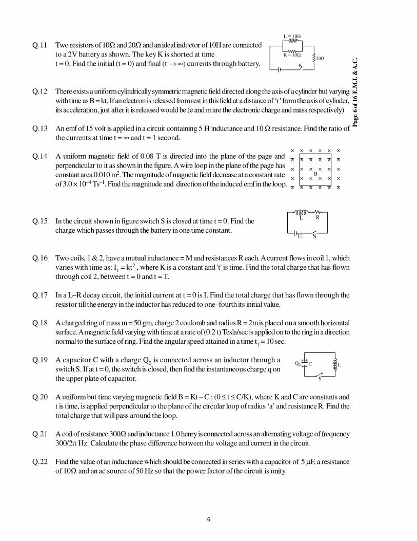
Page
6 o
f 16 E
.M.I
. & A
.C.
Q.11 Two resistors of 10Ω and 20Ω and an ideal inductor of 10H are connected
to a 2V battery as shown. The key K is shorted at time
t = 0. Find the initial (t = 0) and final (t → ∞) currents through battery.
Q.12 There exists a uniform cylindrically symmetric magnetic field directed along the axis of a cylinder but varying
with time as B = kt. If an electron is released from rest in this field at a distance of ‘r’ from the axis of cylinder,
its acceleration, just after it is released would be (e and m are the electronic charge and mass respectively)
Q.13 An emf of 15 volt is applied in a circuit containing 5 H inductance and 10 Ω resistance. Find the ratio of
the currents at time t = ∞ and t = 1 second.
Q.14 A uniform magnetic field of 0.08 T is directed into the plane of the page and
perpendicular to it as shown in the figure. A wire loop in the plane of the page has
constant area 0.010 m2. The magnitude of magnetic field decrease at a constant rate
of 3.0 × 10⁻⁴ Ts–1. Find the magnitude and direction of the induced emf in the loop.
Q.15 In the circuit shown in figure switch S is closed at time t = 0. Find the
charge which passes through the battery in one time constant.
Q.16 Two coils, 1 & 2, have a mutual inductance = M and resistances R each. A current flows in coil 1, which
varies with time as: I1 = kt2 , where K is a constant and 't' is time. Find the total charge that has flown
through coil 2, between t = 0 and t = T.
Q.17 In a L–R decay circuit, the initial current at t = 0 is I. Find the total charge that has flown through the
resistor till the energy in the inductor has reduced to one–fourth its initial value.
Q.18 A charged ring of mass m = 50 gm, charge 2 coulomb and radius R = 2m is placed on a smooth horizontal
surface. A magnetic field varying with time at a rate of (0.2 t) Tesla/sec is applied on to the ring in a direction
normal to the surface of ring. Find the angular speed attained in a time t1 = 10 sec.
Q.19 A capacitor C with a charge Q0 is connected across an inductor through a
switch S. If at t = 0, the switch is closed, then find the instantaneous charge q on
the upper plate of capacitor.
Q.20 A uniform but time varying magnetic field B = Kt – C ; (0 ≤ t ≤ C/K), where K and C are constants and
t is time, is applied perpendicular to the plane of the circular loop of radius ‘a’ and resistance R. Find the
total charge that will pass around the loop.
Q.21 A coil of resistance 300Ω and inductance 1.0 henry is connected across an alternating voltage of frequency
300/2π Hz. Calculate the phase difference between the voltage and current in the circuit.
Q.22 Find the value of an inductance which should be connected in series with a capacitor of 5 µF, a resistance
of 10Ω and an ac source of 50 Hz so that the power factor of the circuit is unity.
6
Page
7 o
f 16 E
.M.I
. & A
.C.
Q.23 In an L-R series A.C circuit the potential difference across an inductance and resistance joined in series
are respectively 12 V and 16V. Find the total potential difference across the circuit.
Q.24 When 100 volt D.C. is applied across a coil, a current of one ampere flows through it, when 100 V ac
of 50 Hz is applied to the same coil, only 0.5 amp flows. Calculate the resistance and inductance of the
coil.
Q.25 A 50W, 100V lamp is to be connected to an ac mains of 200V, 50Hz. What capacitance is essential to
be put in seirs with the lamp.
List of recommended questions from I.E. Irodov.
3.288 to 3.299, 3.301 to 3.309, 3.311, 3.313, 3.315, 3.316, 3.326 to 3.329, 3.331,
3.333 to 3.335, 4.98, 4.99, 4.100, 4.134, 4.135, 4.121,
4.124, 4.125, 4.126, 4.136, 4.137, 4.141, 4.144
7
Page
8 o
f 16 E
.M.I
. & A
.C.
EXERCISE–II
Q.1 Two straight conducting rails form a right angle where their ends are joined. A
conducting bar contact with the rails starts at vertex at the time t = 0 & moves
symmetrically with a constant velocity of 5.2 m/s to the right as shown in figure.
A 0.35 T magnetic field points out of the page. Calculate:
(i) The flux through the triangle by the rails & bar at t = 3.0 s.
(ii) The emf around the triangle at that time.
(iii) In what manner does the emf around the triangle vary with time .
Q.2 Two long parallel rails, a distance l apart and each having a resistance λper unit length are joined at one end by a resistance R. A perfectly
conducting rod MN of mass m is free to slide along the rails without
friction. There is a uniform magnetic field of induction B normal to the
plane of the paper and directed into the paper. A variable force F is
applied to the rod MN such that, as the rod moves, a constant current
i flows through R. Find the velocity of the rod and the applied force F as
function of the distance x of the rod from R
Q.3 A wire is bent into 3 circular segments of radius r = 10 cm as shown in
figure . Each segment is a quadrant of a circle, ab lying in the xy plane,
bc lying in the yz plane & ca lying in the zx plane.
(i) if a magnetic field B points in the positive x direction, what is the
magnitude of the emf developed in the wire, when B increases at the
rate of 3 mT/s ?
(ii) what is the direction of the current in the segment bc.
Q.4 Consider the possibility of a new design for an electric train. The engine is driven by the force due to the
vertical component of the earths magnetic field on a conducting axle. Current is passed down one coil,
into a conducting wheel through the axle, through another conducting wheel & then back to the source
via the other rail.
(i) what current is needed to provide a modest 10 − KN force ? Take the vertical component of the
earth's field be 10 µT & the length of axle to be 3.0 m .
(ii) how much power would be lost for each Ω of resistivity in the rails ?
(iii) is such a train unrealistic ?
Q.5 A square wire loop with 2 m sides in perpendicular to a uniform magnetic field,
with half the area of the loop in the field . The loop contains a 20 V battery with
negligible internal resistance. If the magnitude of the field varies with time
according to B = 0.042 − 0.87 t, with B in tesla & t in sec.
(i) What is the total emf in the circuit ?
(ii) What is the direction of the current through the battery ?
Q.6 A rectangular loop of dimensions l & w and resistance R moves with
constant velocity V to the right as shown in the figure. It continues to
move with same speed through a region containing a uniform magnetic
field B directed into the plane of the paper & extending a distance 3 W.
Sketch the flux, induced emf & external force acting on the loop as a
function of the distance.
8
Page
9 o
f 16 E
.M.I
. & A
.C.
Q.7 A rectangular loop with current I has dimension as shown in figure . Find the magnetic
flux φ through the infinite region to the right of line PQ.
Q.8 A square loop of side 'a' & resistance R moves with a uniform velocity
v away from a long wire that carries current I as shown in the figure.
The loop is moved away from the wire with side AB always parallel to
the wire. Initially, distance between the side AB of the loop & wire is
'a'. Find the work done when the loop is moved through distance 'a'
from the initial position.
Q.9 Two long parallel conducting horizontal rails are connected by a conducting
wire at one end. A uniform magnetic field B exists in the region of space. A
light uniform ring of diameter d which is practically equal to separation
between the rails, is placed over the rails as shown in the figure. If resistance
of ring is λ per unit length, calculate the force required to pull the ring with
uniform velocity v.
Q.10 A long straight wire is arranged along the symmetry axis of a toroidal coil of
rectangular cross−section, whose dimensions are given in the figure. The number
of turns on the coil is N, and permeability of the surrounding medium is unity.
Find the amplitude of the emf induced in this coil, if the current i = im cos ωt
flows along the straight wire.
Q.11 A uniform magnetic field B
fills a cylindrical volumes of radius R. A metal
rod CD of length l is placed inside the cylinder along a chord of the circular
cross-section as shown in the figure. If the magnitude of magnetic field
increases in the direction of field at a constant rate dB/dt, find the magnitude
and direction of the EMF induced in the rod.
Q.12 A variable magnetic field creates a constant emf E in a conductor ABCDA.
The resistances of portion ABC, CDA and AMC are R1, R
2 and R
3
respectively. What current will be shown by meter M? The magnetic field
is concentrated near the axis of the circular conductor.
Q.13 In the circuit shown in the figure the switched S1 and S
2 are
closed at time t = 0. After time t = (0.1) ln 2 sec, switch S2 is
opened. Find the current in the circuit at time t = (0.2) ln 2 sec.
Q.14 Find the values of i1 and i
2
(i) immediately after the switch S is closed.
(ii) long time later, with S closed.
(iii) immediately after S is open.
(iv) long time after S is opened.
9
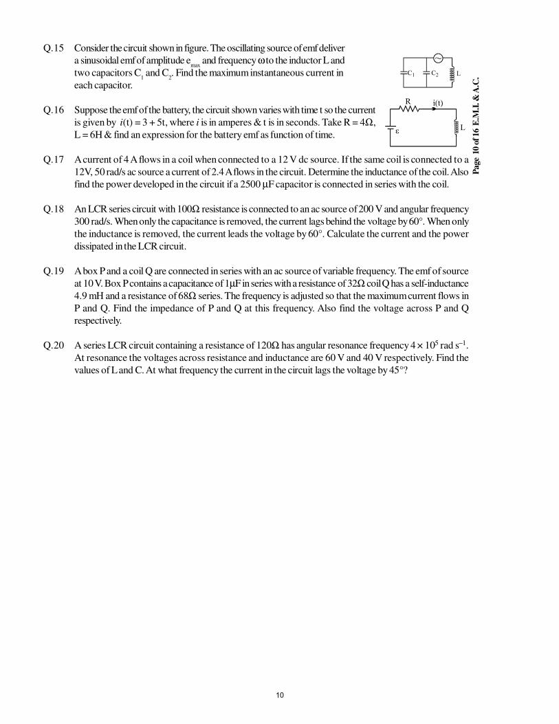
Page
10 o
f 16 E
.M.I
. & A
.C.
Q.15 Consider the circuit shown in figure. The oscillating source of emf deliver
a sinusoidal emf of amplitude emax
and frequency ω to the inductor L and
two capacitors C1 and C
2. Find the maximum instantaneous current in
each capacitor.
Q.16 Suppose the emf of the battery, the circuit shown varies with time t so the current
is given by i(t) = 3 + 5t, where i is in amperes & t is in seconds. Take R = 4Ω,
L = 6H & find an expression for the battery emf as function of time.
Q.17 A current of 4 A flows in a coil when connected to a 12 V dc source. If the same coil is connected to a
12V, 50 rad/s ac source a current of 2.4 A flows in the circuit. Determine the inductance of the coil. Also
find the power developed in the circuit if a 2500 µF capacitor is connected in series with the coil.
Q.18 An LCR series circuit with 100Ω resistance is connected to an ac source of 200 V and angular frequency
300 rad/s. When only the capacitance is removed, the current lags behind the voltage by 60°. When only
the inductance is removed, the current leads the voltage by 60°. Calculate the current and the power
dissipated in the LCR circuit.
Q.19 A box P and a coil Q are connected in series with an ac source of variable frequency. The emf of source
at 10 V. Box P contains a capacitance of 1µF in series with a resistance of 32Ω coil Q has a self-inductance
4.9 mH and a resistance of 68Ω series. The frequency is adjusted so that the maximum current flows in
P and Q. Find the impedance of P and Q at this frequency. Also find the voltage across P and Q
respectively.
Q.20 A series LCR circuit containing a resistance of 120Ω has angular resonance frequency 4 × 10⁵ rad s–1.
At resonance the voltages across resistance and inductance are 60 V and 40 V respectively. Find the
values of L and C. At what frequency the current in the circuit lags the voltage by 45°?
10
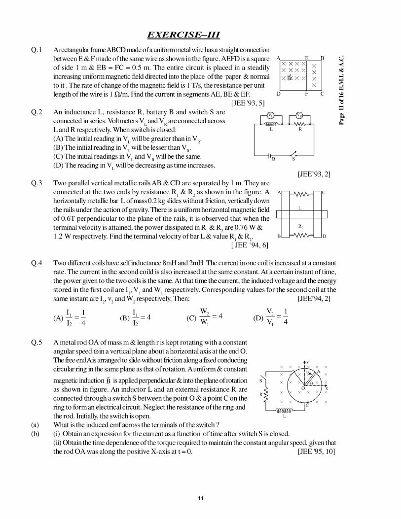
Page
11 o
f 16 E
.M.I
. & A
.C.
EXERCISE–III
Q.1 A rectangular frame ABCD made of a uniform metal wire has a straight connection
between E & F made of the same wire as shown in the figure. AEFD is a square
of side 1 m & EB = FC = 0.5 m. The entire circuit is placed in a steadily
increasing uniform magnetic field directed into the place of the paper & normal
to it . The rate of change of the magnetic field is 1 T/s, the resistance per unit
length of the wire is 1 Ω/m. Find the current in segments AE, BE & EF.
[JEE '93, 5]
Q.2 An inductance L, resistance R, battery B and switch S are
connected in series. Voltmeters VL and V
R are connected across
L and R respectively. When switch is closed:
(A) The initial reading in VL will be greater than in V
R.
(B) The initial reading in VL will be lesser than V
R.
(C) The initial readings in VL and V
R will be the same.
(D) The reading in VL will be decreasing as time increases.
[JEE’93, 2]
Q.3 Two parallel vertical metallic rails AB & CD are separated by 1 m. They are
connected at the two ends by resistance R1 & R
2 as shown in the figure. A
horizontally metallic bar L of mass 0.2 kg slides without friction, vertically down
the rails under the action of gravity. There is a uniform horizontal magnetic field
of 0.6T perpendicular to the plane of the rails, it is observed that when the
terminal velocity is attained, the power dissipated in R1 & R
2 are 0.76 W &
1.2 W respectively. Find the terminal velocity of bar L & value R1 & R
2.
[ JEE '94, 6]
Q.4 Two different coils have self inductance 8mH and 2mH. The current in one coil is increased at a constant
rate. The current in the second coild is also increased at the same constant. At a certain instant of time,
the power given to the two coils is the same. At that time the current, the induced voltage and the energy
stored in the first coil are I1, V
1 and W
1 respectively. Corresponding values for the second coil at the
same instant are I2, v
2 and W
2 respectively. Then: [JEE’94, 2]
(A) I
I
1
2
1
4= (B)
I
I
1
2
4= (C) W
W
2
1
4= (D)V
V
2
1
1
4=
Q.5 A metal rod OA of mass m & length r is kept rotating with a constant
angular speed ω in a vertical plane about a horizontal axis at the end O.
The free end A is arranged to slide without friction along a fixed conducting
circular ring in the same plane as that of rotation. A uniform & constant
magnetic induction B is applied perpendicular & into the plane of rotation
as shown in figure. An inductor L and an external resistance R are
connected through a switch S between the point O & a point C on the
ring to form an electrical circuit. Neglect the resistance of the ring and
the rod. Initially, the switch is open.
(a) What is the induced emf across the terminals of the switch ?
(b) (i) Obtain an expression for the current as a function of time after switch S is closed.
(ii) Obtain the time dependence of the torque required to maintain the constant angular speed, given that
the rod OA was along the positive X-axis at t = 0. [JEE '95, 10]
11

Page
12 o
f 16 E
.M.I
. & A
.C.
Q.6 A solenoid has an inductance of 10 Henry & a resistance of 2 Ω. It is connected to a 10 volt battery.
How long will it take for the magnetic energy to reach 1/4 of its maximum value ?
[JEE '96, 3]
Q.7 Select the correct alternative.
A thin semicircular conducting ring of radius R is falling with its plane vertical in
a horizontal magnetic induction B . At the position MNQ the speed of the ring is
v & the potential difference developed across the ring is :
(A) zero (B) Bv Rπ 2
2 & M is at higher potential
(C) π RBV & Q is at higher potential (D) 2 RBV & Q is at higher potential
[JEE'96, 2]
Q.8 Fill in the blank.
A metallic block carrying current I is subjected to a uniform magnetic induction
B j . The moving charges experience a force F given by ______ which results
in the lowering of the potential of the face ______.
[assume the speed of the carrier to be v] [JEE '96, 2]
Q.9 A pair of parallel horizontal conducting rails of negligible resistance shorted
at one end is fixed on a table. The distance between the rails is L. A
conducting massless rod of resistance R can slide on the rails frictionlessly.
The rod is tied to a massless string which passes over a pulley fixed to the
edge of the table. A mass m, tied to the other end of the string hangs
vertically. A constant magnetic field B exists perpendicular to the table. If
the system is released from rest, calculate:
(i) the terminal velocity achieved by the rod.
(ii) the acceleration of the mass at the instant when the velocity of the rod is half the terminal velocity.
[JEE '97, 5]
Q.10 A current i = 3.36 (1 + 2t) × 10−2 A increases at a steady rate in a long straight wire. A small circular loop
of radius 10−3 m is in the plane of the wire & is placed at a distance of 1 m from the wire. The resistance
of the loop is 8.4 x 10⁻² Ω. Find the magnitude & the direction of the induced current in the loop.
[REE '98, 5]
Q.11 Select the correct alternative(s). [ JEE '98, 3 × 2 = 6 ,4×2=8]
(i) The SI unit of inductance, the Henry, can be written as :
(A) weber/ampere (B) volt − second/ampere
(C) joule/(ampere)2 (D) ohm − second
(ii) A small square loop of wire of side l is placed inside a large square loop of wire of side L(L >> l). The
loop are co-planar & their centres coincide. The mutual inductance of the system is proportional to :
(A)
L(B)
2
L(C)
L
(D)
L2
(iii) A metal rod moves at a constant velocity in a direction perpendicular to its length . A constant, uniform
magnetic field exists in space in a direction perpendicular to the rod as well as its velocity. Select the
correct statement(s) from the following
(A) the entire rod is at the same electric potential
(B) there is an electric field in the rod
(C) the electric potential is highest at the centre of the rod & decreases towards its ends
(D) the electric potential is lowest at the centre of the rod & increases towards its ends.
12
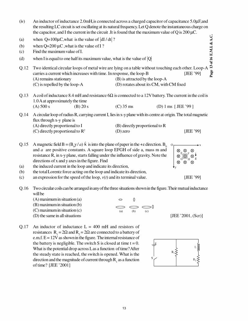
Page
13 o
f 16 E
.M.I
. & A
.C.
(iv) An inductor of inductance 2.0mH,is connected across a charged capacitor of capacitance 5.0µF,and
the resulting LC circuit is set oscillating at its natural frequency. Let Q denote the instantaneous charge on
the capacitor, and I the current in the circuit .It is found that the maximum value of Q is 200 µC.
(a) when Q=100µC,what is the value of dI dt/ ?
(b) when Q=200 µC ,what is the value of I ?
(c) Find the maximum value of I.
(d) when I is equal to one half its maximum value, what is the value of Q
Q.12 Two identical circular loops of metal wire are lying on a table without touching each other. Loop-A
carries a current which increases with time. In response, the loop-B [JEE ’99]
(A) remains stationary (B) is attracted by the loop-A
(C) is repelled by the loop-A (D) rotates about its CM, with CM fixed
Q.13 A coil of inductance 8.4 mH and resistance 6Ω is connected to a 12V battery. The current in the coil is
1.0 A at approximately the time
(A) 500 s (B) 20 s (C) 35 ms (D) 1 ms [ JEE ’99 ]
Q.14 A circular loop of radius R, carrying current I, lies in x-y plane with its centre at origin. The total magnetic
flux through x-y plane is
(A) directly proportional to I (B) directly proportional to R
(C) directly proportional to R2 (D) zero [JEE ’99]
Q.15 A magnetic field B = (B0y / a) k is into the plane of paper in the +z direction. B
0
and a are positive constants. A square loop EFGH of side a, mass m and
resistance R, in x-y plane, starts falling under the influence of gravity. Note the
directions of x and y axes in the figure. Find
(a) the induced current in the loop and indicate its direction,
(b) the total Lorentz force acting on the loop and indicate its direction,
(c) an expression for the speed of the loop, v(t) and its terminal value. [JEE ’99]
Q.16 Two circular coils can be arranged in any of the three situations shown in the figure. Their mutual inductance
will be
(A) maximum in situation (a)
(B) maximum in situation (b)
(C) maximum in situation (c)
(D) the same in all situations [JEE ’2001, (Scr)]
Q.17 An inductor of inductance L = 400 mH and resistors of
resistances R1 = 2Ω and R
2 = 2Ω are connected to a battery of
e.m.f. E = 12V as shown in the figure. The internal resistance of
the battery is negligible. The switch S is closed at time t = 0.
What is the potential drop across L as a function of time? After
the steady state is reached, the switch is opened. What is the
direction and the magnitude of current through R1 as a function
of time? [JEE ’2001]
13
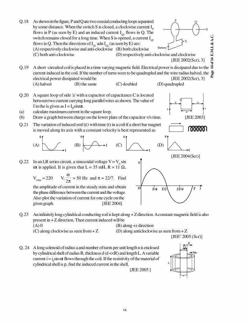
Page
14 o
f 16 E
.M.I
. & A
.C.
Q.18 As shown in the figure, P and Q are two coaxial conducting loops separated
by some distance. When the switch S is closed, a clockwise current IP
flows in P (as seen by E) and an induced current IQ1
flows in Q. The
switch remains closed for a long time. When S is opened, a current IQ2
flows in Q. Then the directions of IQ1
adn IQ2
(as seen by E) are:
(A) respectively clockwise and anti-clockwise (B) both clockwise
(C) both anti-clockwise (D) respectively anti-clockwise and clockwise
[JEE 2002(Scr), 3]
Q.19 A short -circuited coil is placed in a time varying magnetic field. Electrical power is dissipated due to the
current induced in the coil. If the number of turns were to be quadrupled and the wire radius halved, the
electrical power dissipated would be [JEE 2002(Scr), 3]
(A) halved (B) the same (C) doubled (D) quadrupled
Q.20 A square loop of side 'a' with a capacitor of capacitance C is located
between two current carrying long parallel wires as shown. The value of
I in the is given as I = I0sinωt.
(a) calculate maximum current in the square loop.
(b) Draw a graph between charge on the lower plate of the capacitor v/s time. [JEE 2003]
Q.21 The variation of induced emf (ε) with time (t) in a coil if a short bar magnet
is moved along its axis with a constant velocity is best represented as
(A) (B) (C) (D)
[JEE 2004(Scr)]
Q.22 In an LR series circuit, a sinusoidal voltage V = Vo sin
ωt is applied. It is given that L = 35 mH, R = 11 Ω,
Vrms
= 220 V,π
ω2
= 50 Hz and π = 22/7. Find
the amplitude of current in the steady state and obtain
the phase difference between the current and the voltage.
Also plot the variation of current for one cycle on the
given graph. [JEE 2004]
t
V
O T/4 T/2 3T/4 T
Q.23 An infinitely long cylindrical conducting rod is kept along + Z direction. A constant magnetic field is also
present in + Z direction. Then current induced will be
(A) 0 (B) along +z direction
(C) along clockwise as seen from + Z (D) along anticlockwise as seen from + Z
[JEE’ 2005 (Scr)]
Q. 24 A long solenoid of radius a and number of turns per unit length n is enclosed
by cylindrical shell of radius R, thickness d (d <<R) and length L. A variable
current i = i0sin ωt flows through the coil. If the resistivity of the material of
cylindrical shell is ρ, find the induced current in the shell.
[JEE 2005 ]
14
Page
15 o
f 16 E
.M.I
. & A
.C.
Q.25 In the given diagram, a line of force of a particular force field is shown. Out of the following options, it
can never represent
(A) an electrostatic field
(B) a magnetostatic field
(C) a gravitational field of a mass at rest
(D) an induced electric field [JEE 2006]
Comprehension –I
The capacitor of capacitance C can be charged (with the help of a
resistance R) by a voltage source V, by closing switch S1 while keeping
switch S2 open. The capacitor can be connected in series
with an inductor ‘L’ by closing switch S2 and opening S
1.
R S1
S2
V
C
L
Q.26 Initially, the capacitor was uncharged. Now, switch S1 is closed and S
2 is kept open. If time constant of
this circuit is τ, then
(A) after time interval τ, charge on the capacitor is CV/2
(B) after time interval 2τ, charge on the capacitor is CV(1–e–2)
(C) the work done by the voltage source will be half of the heat dissipated when the capacitor is fully
charged.
(D) after time interval 2τ, charge on the capacitor is CV(1–e–1) [JEE 2006]
Q.27 After the capacitor gets fully charged, S1 is opened and S
2 is closed so that the inductor is connected in
series with the capacitor. Then,
(A) at t = 0, energy stored in the circuit is purely in the form of magnetic energy
(B) at any time t > 0, current in the circuit is in the same direction
(C) at t > 0, there is no exchange of energy between the inductor and capacitor
(D) at any time t > 0, instantaneous current in the circuit may L
CV [JEE 2006]
Q.28 If the total charge stored in the LC circuit is Q0, then for t ≥ 0
(A) the charge on the capacitor is
+
π=
LC
t
2cosQQ
0
(B) the charge on the capacitor is
−
π=
LC
t
2cosQQ
0
(C) the charge on the capacitor is 2
2
dt
QdLCQ −=
(D) the charge on the capacitor is 2
2
dt
Qd
LC
1Q −= [JEE 2006]
15
Page
16 o
f 16 E
.M.I
. & A
.C.
Comprehension –IV
Magler Train: This train is based on the Lenz law and phenomena of electromagnetic induction. In this
there is a coil on a railway track and magnet on the base of train. So as train is deviated then as is move
down coil on track repel it and as it move up then coil attract it.
Disadvantage of magler train is that as it slow down the forces decreases and as it moves forward so due
to Lenz law coil attract it backward.
Due to motion of train current induces in the coil of track which levitate it.
Q.29 What is the advantage of the train? [JEE 2006]
(A) Electrostatic force draws the train (B) Gravitational force is zero.
(C) Electromagnetic force draws the train (D) Dissipative force due to friction are absent
Q.30 What is the disadvantage of the train?
(A) Train experience upward force due to Lenz's law.
(B) Friction force create a drag on the train.
(C) Retardation
(D) By Lenz's law train experience a drag [JEE 2006]
Q.31 Which force causes the train to elevate up
(A) Electrostatic force (B) Time varying electric field
(C) magnetic force (D) Induced electric field [JEE 2006]
Q.32 Match the following Columns
Column 1 Column 2
(A) Dielectric ring uniformly charged (P) Time independent electrostatic field out of
system
(B) Dielectric ring uniformly charged (Q) Magnetic field
rotating with angular velocity .
(C) Constant current in ring i0
(R) Induced electric field
( D ) C u r r e n t i = i( D ) C u r r e n t i = i( D ) C u r r e n t i = i( D ) C u r r e n t i = i0 cos ωt in ring (S) Magnetic moment [JEE 2006]
16
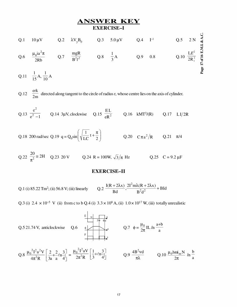
Page
17 o
f 16 E
.M.I
. & A
.C.
ANSWER KEYEXERCISE–I
Q.1 10 µV Q.2 λVyB
0Q.3 5.0 µV Q.4 I–1 Q.5 2 N
Q.6Rb2
ia20
πµQ.7 2l2B
mgRQ.8
3
1A Q.9 0.8 Q.10 2
1
2
R2
LE
Q.111
15A,
1
10A
Q.12m2
erk directed along tangent to the circle of radius r, whose centre lies on the axis of cylinder..
Q.131e
e2
2
−Q.14 3µV, clockwise Q.15 2eR
LEQ.16 kMT2/(R) Q.17 R2IL
Q.18 200 rad/sec Q.19 q = Q0sin
π+
2t
LC
1Q.20 RaC
2π Q.21 π/4
Q.22 H220
2≅
πQ.23 20 V Q.24 R = 100W, π3 Hz Q.25 C = 9.2 µF
EXERCISE–II
Q.1 (i) 85.22 Tm2; (ii) 56.8 V; (iii) linearly Q.2 BIddB
)x2R(mI2,
Bd
)x2R(I22
2
+λ+λλ+
Q.3 (i) 2.4 × 10⁻⁵ V (ii) from c to b Q.4 (i) 3.3 × 10⁸ A, (ii) 1.0 × 10¹⁷ W, (iii) totally unrealistic
Q.5 21.74 V, anticlockwise Q.6 Q.7 φ =
π
µ
2
0IL ln
a
ba+
Q.8 R4
VaI2
2220
π
µ
+
4
3n
a
2
a3
2 =
R2
aVI2
220
π
µ
+4
3n
3
1 Q.9
πλνdB4 2
Q.10 π
ωµ2
Nih m0 ln
a
b
17
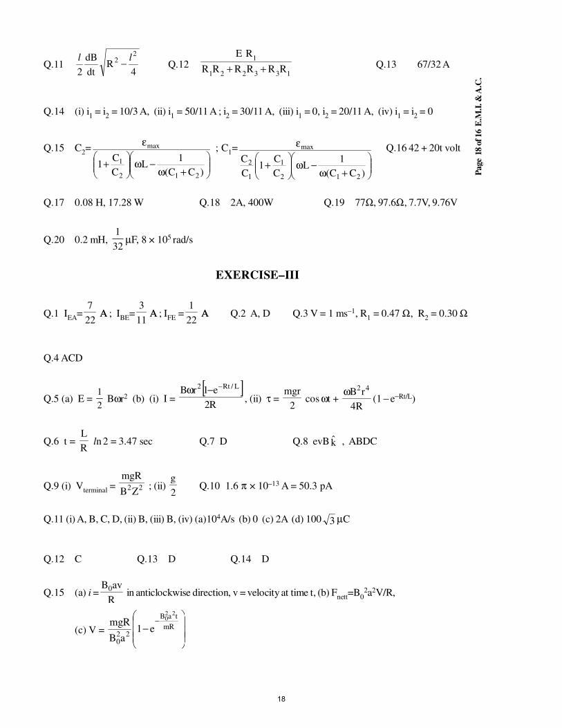
Page
18 o
f 16 E
.M.I
. & A
.C.
Q.114
Rdt
dB
2
22 ll
− Q.12133221
1
RRRRRR
RE
++ Q.13 67/32 A
Q.14 (i) i1 = i
2 = 10/3 A, (ii) i
1 = 50/11 A ; i
2 = 30/11 A, (iii) i
1 = 0, i
2 = 20/11 A, (iv) i
1 = i
2 = 0
Q.15 C2=
+ω−ω
+
ε
)CC(
1L
C
C1
212
1
max ; C1=
+ω−ω
+
ε
)CC(
1L
C
C1
C
C
212
1
1
2
max Q.16 42 + 20t volt
Q.17 0.08 H, 17.28 W Q.18 2A, 400W Q.19 77Ω, 97.6Ω, 7.7V, 9.76V
Q.20 0.2 mH, 32
1µF, 8 × 10⁵ rad/s
EXERCISE–III
Q.1 IEA
=22
7 AA ; I
BE=
11
3 AA ; I
FE =
22
1 AA Q.2 A, D Q.3 V = 1 ms−1, R
1 = 0.47 Ω, R
2 = 0.30 Ω
Q.4 ACD
Q.5 (a) E = 1
2 Bωr2 (b) (i) I =
[ ]R2
e1rB L/Rt2 −−ω, (ii) τ =
2
mgr cos ωt +
R4
rB 42ω(1 − e−Rt/L)
Q.6 t = R
L ln 2 = 3.47 sec Q.7 D Q.8 evB k , ABDC
Q.9 (i) Vterminal
= 22ZB
Rmg ; (ii)
2
gQ.10 1.6 π × 10–13 A = 50.3 pA
Q.11 (i) A, B, C, D, (ii) B, (iii) B, (iv) (a)104A/s (b) 0 (c) 2A (d) 100 3 µC
Q.12 C Q.13 D Q.14 D
Q.15 (a) i =R
avB0 in anticlockwise direction, v = velocity at time t, (b) F
nett=B
02a2V/R,
(c) V =
−
−mR
taB
220
220
e1aB
mgR
18
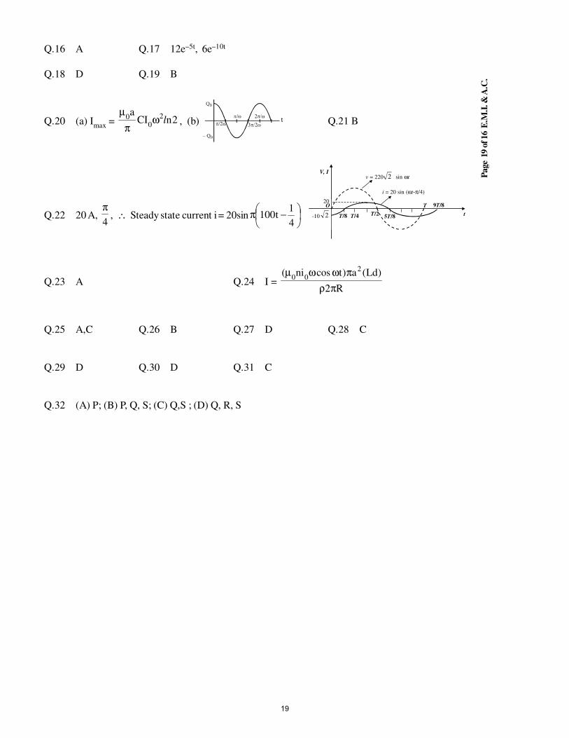
Page
19 o
f 16 E
.M.I
. & A
.C.
Q.16 A Q.17 12e–5t, 6e–10t
Q.18 D Q.19 B
Q.20 (a) Imax
= 2nCIa 2
00 lωπ
µ, (b) Q.21 B
Q.22 20 A, 4
π, ∴ Steady state current i = 20sin
−π4
1t100 T/8
V, I
O
T/4 T/2 5T/8
T 20
-10 2
9T/8
t
v = 220 2 sin ωt
i = 20 sin (ωt-π/4)
Q.23 A Q.24 I = R2
)Ld(a)tcosni( 200
πρ
πωωµ
Q.25 A,C Q.26 B Q.27 D Q.28 C
Q.29 D Q.30 D Q.31 C
Q.32 (A) P; (B) P, Q, S; (C) Q,S ; (D) Q, R, S
19
STUDY PACKAGE
Target: IIT-JEE (Advanced)
SUBJECT: PHYSICS
TOPIC: XII P7. Optics
Index:
1. Key Concepts
2. Exercise I
3. Exercise II
4. Exercise III
5. Exercise IV
6. Answer Key
7. 34 Yrs. Que. from IIT-JEE
8. 10 Yrs. Que. from AIEEE
1
Page
2 o
f 20 G
EO
ME
TR
ICA
L O
PT
ICS
KEY CONCEPTS
1. LAWS OF REFLECTION :
(i) The incident ray (AB), the reflected ray (BC) and normal (NN') to the surface (SC') of reflection at the
point of incidence (B) lie in the same plane. This plane is called the plane of incidence (also plane of
reflection).
(ii) The angle of incidence (the angle between normal and the incident
ray) and the angle of reflection (the angle between the reflected ray
and the normal) are equal
∠∠∠∠ i = ∠∠∠∠ r
2. OBJECT :
(a) Real : Point from which rays actually diverge.
(b) Virtual : Point towards which rays appear to converge
3. IMAGE :
Image is decided by reflected or refracted rays only. The point image for a mirror is that point
(i) Towards which the rays reflected from the mirror, actually converge (real image).
OR
(ii) From which the reflected rays appear to diverge (virtual image) .
4. CHARACTERISTICS OF REFLECTION BY A PLANE MIRROR :
(a) The size of the image is the same as that of the object.
(b) For a real object the image is virtual and for a virtual object the image is real.
(c) For a fixed incident light ray, if the mirror be rotated through an angle θ the reflected ray turns through
an angle 2θ.
5. SPHERICAL MIRRORS :
Concave Convex
6. PARAXIAL RAYS : Rays which forms very small angle with axis are called paraxial rays.
7. SIGN CONVENTION :
We follow cartesian co-ordinate system convention according to which
(a) The pole of the mirror is the origin .
(b) The direction of the incident rays is considered as positive x-axis.
(c) Vertically up is positive y-axis.
Note : According to above convention radius of curvature and focus of concave mirror is negative and ofconvex mirror is positive.
8. MIRROR FORMULA :1
f =
1 1
v u+ .
f = x- coordinate of focus ; u = x-coordinate of object ;
v = x-coordinate of image
Note : Valid only for paraxial rays.
2
Page
3 o
f 20 G
EO
ME
TR
ICA
L O
PT
ICS
9. TRANSVERSE MAGNIFICATION : m =h
h
2
1
= −v
u
h2 = y co-ordinate of images h
1 = y co-ordinate of the object
(both perpendicular to the principle axis of mirror)
10. NEWTON'S FORMULA :
Applicable to a pair of real object and real image position only . They are called conjugate positions
or foci. X,Y are the distance along the principal axis of the real object and real image respectively from
the principal focus .
XY = f 2
11. OPTICAL POWER : Optical power of a mirror (in Diopters) = –1
f ;
f = focal length (in meters) with sign .
REFRACTION -PLANE SURFACE
1. LAWS OF REFRACTION (AT ANY REFRACTING SURFACE) :
(i) The incident ray (AB), the normal (NN') to the refracting surface (II') at the point of incidence (B) and
the refracted ray (BC) all lie in the same plane called the plane of incidence or plane of refraction .
(ii)Sin i
Sin r = Constant :
for any two given media and for light of a given wave length. This is known as
SNELL'S Law .
Sin i
Sin r=
1n
2 =
n
n
2
1
= v
v
1
2
= λ
λ1
2
Note : Frequency of light does not change during refraction .
2. DEVIATION OF A RAY DUE TO REFRACTION :
3. REFRACTION THROUGH A PARALLEL SLAB :
(i) Emerged ray is parallel to the incident ray, if medium is same on
both sides.
(ii) Lateral shift x = t i r
r
sin( )
cos
−
t = thickness of slab
Note : Emerged ray will not be parallel to the incident ray if the medium on both the sides
are different .
3
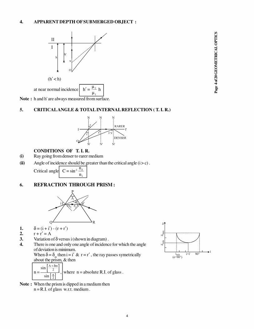
Page
4 o
f 20 G
EO
ME
TR
ICA
L O
PT
ICS
4. APPARENT DEPTH OF SUBMERGED OBJECT :
(h′ < h)
at near normal incidence h′ = µ
µ2
1
h
Note : h and h' are always measured from surface.
5. CRITICAL ANGLE & TOTAL INTERNAL REFLECTION ( T. I. R.)
CONDITIONS OF T. I. R.(i) Ray going from denser to rarer medium
(ii) Angle of incidence should be greater than the critical angle (i > c) .
Critical angle C = sin-1
i
r
n
n
6. REFRACTION THROUGH PRISM :
1. δ = (i + i′) - (r + r′)2. r + r′ = A
3. Variation of δ versus i (shown in diagram) .
4. There is one and only one angle of incidence for which the angleof deviation is minimum.When δ = δ
m then i = i′ & r = r′ , the ray passes symetrically
about the prism, & then
n =[ ]
[ ]sin
sin
A m
A
+ δ2
2
, where n = absolute R.I. of glass .
Note : When the prism is dipped in a medium thenn = R.I. of glass w.r.t. medium .
4
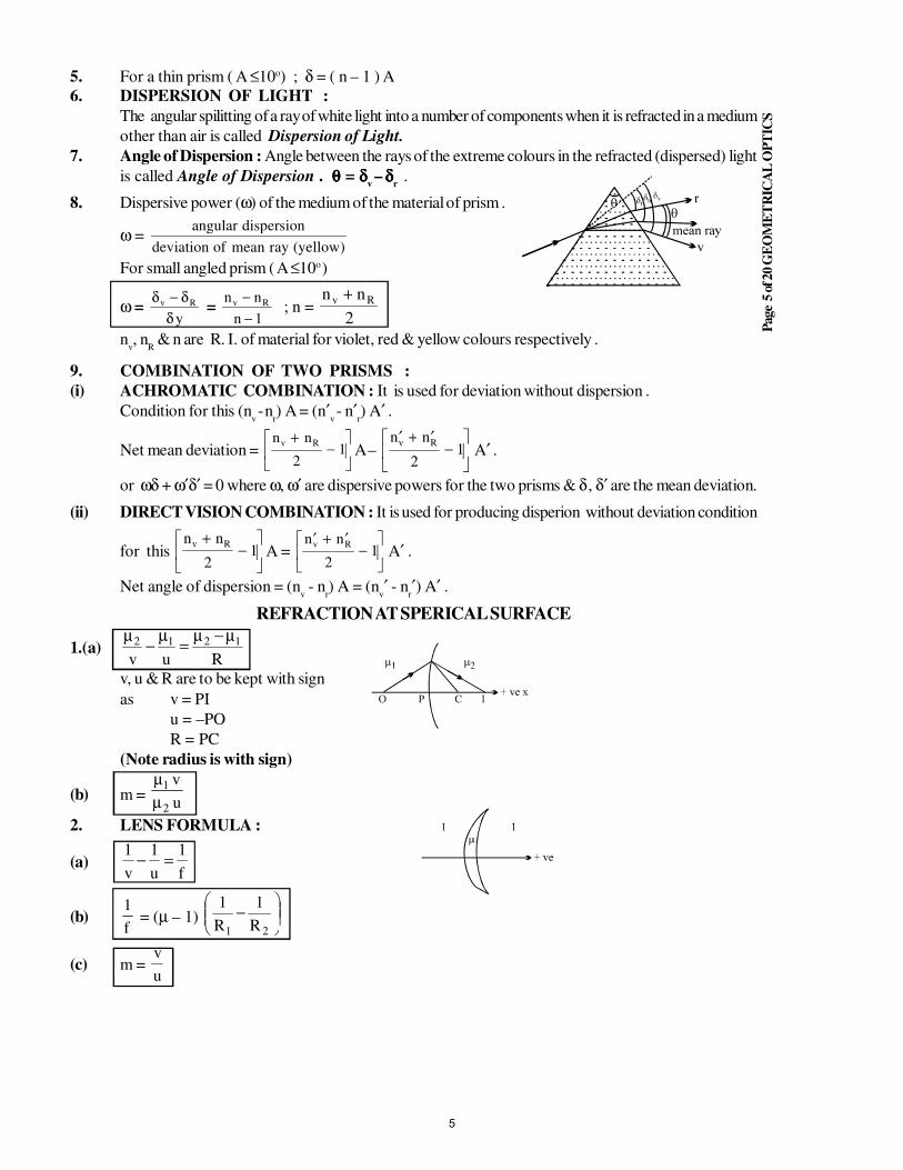
Page
5 o
f 20 G
EO
ME
TR
ICA
L O
PT
ICS
5. For a thin prism ( A ≤10o) ; δ = ( n – 1 ) A
6. DISPERSION OF LIGHT :
The angular spilitting of a ray of white light into a number of components when it is refracted in a medium
other than air is called Dispersion of Light.
7. Angle of Dispersion : Angle between the rays of the extreme colours in the refracted (dispersed) light
is called Angle of Dispersion . θθθθ = δδδδv
– δδδδr .
8. Dispersive power (ω) of the medium of the material of prism .
ω = angular dispersion
deviation of mean ray yellow( )
For small angled prism ( A ≤10o )
ω = δ δ
δv R
y
− =
n n
n
v R−
− 1 ; n =
n nv R+2
nv, n
R & n are R. I. of material for violet, red & yellow colours respectively .
9. COMBINATION OF TWO PRISMS :
(i) ACHROMATIC COMBINATION : It is used for deviation without dispersion .
Condition for this (nv
- nr) A = (n′
v
- n′r) A′ .
Net mean deviation = n nv R+
−
21 A –
′ + ′−
n nv R
21 A′ .
or ωδ + ω′δ′ = 0 where ω, ω′ are dispersive powers for the two prisms & δ , δ′ are the mean deviation.
(ii) DIRECT VISION COMBINATION : It is used for producing disperion without deviation condition
for this n nv R+
−
21 A =
′ + ′−
n nv R
21 A′ .
Net angle of dispersion = (nv - n
r) A = (n
v′ - n
r′) A′ .
REFRACTION AT SPERICAL SURFACE
1.(a)Ruv
1212 µ−µ=
µ−
µ
v, u & R are to be kept with sign
as v = PI
u = –PO
R = PC
(Note radius is with sign)
(b) m = u
v
2
1
µµ
2. LENS FORMULA :
(a)f
1
u
1
v
1=−
(b)f
1= (µ – 1)
−
21 R
1
R
1
(c) m = u
v
5
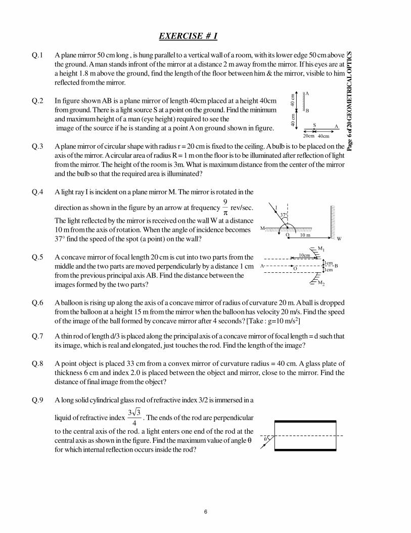
Page
6 o
f 20 G
EO
ME
TR
ICA
L O
PT
ICS
EXERCISE # I
Q.1 A plane mirror 50 cm long , is hung parallel to a vertical wall of a room, with its lower edge 50 cm above
the ground. A man stands infront of the mirror at a distance 2 m away from the mirror. If his eyes are at
a height 1.8 m above the ground, find the length of the floor between him & the mirror, visible to him
reflected from the mirror.
Q.2 In figure shown AB is a plane mirror of length 40cm placed at a height 40cm
from ground. There is a light source S at a point on the ground. Find the minimum
and maximum height of a man (eye height) required to see the
image of the source if he is standing at a point A on ground shown in figure.
Q.3 A plane mirror of circular shape with radius r = 20 cm is fixed to the ceiling. A bulb is to be placed on the
axis of the mirror. A circular area of radius R = 1 m on the floor is to be illuminated after reflection of light
from the mirror. The height of the room is 3m. What is maximum distance from the center of the mirror
and the bulb so that the required area is illuminated?
Q.4 A light ray I is incident on a plane mirror M. The mirror is rotated in the
direction as shown in the figure by an arrow at frequency π
9 rev/sec.
The light reflected by the mirror is received on the wall W at a distance
10 m from the axis of rotation. When the angle of incidence becomes
37° find the speed of the spot (a point) on the wall?
Q.5 A concave mirror of focal length 20 cm is cut into two parts from the
middle and the two parts are moved perpendicularly by a distance 1 cm
from the previous principal axis AB. Find the distance between the
images formed by the two parts?
Q.6 A balloon is rising up along the axis of a concave mirror of radius of curvature 20 m. A ball is dropped
from the balloon at a height 15 m from the mirror when the balloon has velocity 20 m/s. Find the speed
of the image of the ball formed by concave mirror after 4 seconds? [Take : g=10 m/s2]
Q.7 A thin rod of length d/3 is placed along the principal axis of a concave mirror of focal length = d such that
its image, which is real and elongated, just touches the rod. Find the length of the image?
Q.8 A point object is placed 33 cm from a convex mirror of curvature radius = 40 cm. A glass plate of
thickness 6 cm and index 2.0 is placed between the object and mirror, close to the mirror. Find the
distance of final image from the object?
Q.9 A long solid cylindrical glass rod of refractive index 3/2 is immersed in a
liquid of refractive index 4
33. The ends of the rod are perpendicular
to the central axis of the rod. a light enters one end of the rod at the
central axis as shown in the figure. Find the maximum value of angle θfor which internal reflection occurs inside the rod?
6
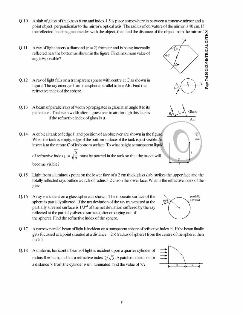
Page
7 o
f 20 G
EO
ME
TR
ICA
L O
PT
ICS
Q.10 A slab of glass of thickness 6 cm and index 1.5 is place somewhere in between a concave mirror and a
point object, perpendicular to the mirror's optical axis. The radius of curvature of the mirror is 40 cm. If
the reflected final image coincides with the object, then find the distance of the object from the mirror?
Q.11 A ray of light enters a diamond (n = 2) from air and is being internally
reflected near the bottom as shown in the figure. Find maximum value of
angle θ possible?
Q.12 A ray of light falls on a transparent sphere with centre at C as shown in
figure. The ray emerges from the sphere parallel to line AB. Find the
refractive index of the sphere.
Q.13 A beam of parallel rays of width b propagates in glass at an angle θ to its
plane face . The beam width after it goes over to air through this face is
_______ if the refractive index of glass is µ.
Q.14 A cubical tank (of edge l) and position of an observer are shown in the figure.
When the tank is empty, edge of the bottom surface of the tank is just visible. An
insect is at the centre C of its bottom surface. To what height a transparent liquid
of refractive index µ = 2
5 must be poured in the tank so that the insect will
become visible?
Q.15 Light from a luminous point on the lower face of a 2 cm thick glass slab, strikes the upper face and the
totally reflected rays outline a circle of radius 3.2 cm on the lower face. What is the refractive index of the
glass.
Q.16 A ray is incident on a glass sphere as shown. The opposite surface of the
sphere is partially silvered. If the net deviation of the ray transmitted at the
partially silvered surface is 1/3rd of the net deviation suffered by the ray
reflected at the partially silvered surface (after emerging out of
the sphere). Find the refractive index of the sphere.
Q.17 A narrow parallel beam of light is incident on a transparent sphere of refractive index 'n'. If the beam finally
gets focussed at a point situated at a distance = 2 × (radius of sphere) from the centre of the sphere, then
find n?
Q.18 A uniform, horizontal beam of light is incident upon a quarter cylinder of
radius R = 5 cm, and has a refractive index 32 . A patch on the table for
a distance 'x' from the cylinder is unilluminated. find the value of 'x'?
7
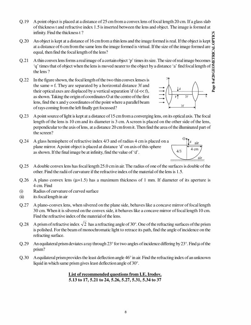
Page
8 o
f 20 G
EO
ME
TR
ICA
L O
PT
ICS
Q.19 A point object is placed at a distance of 25 cm from a convex lens of focal length 20 cm. If a glass slab
of thickness t and refractive index 1.5 is inserted between the lens and object. The image is formed at
infinity. Find the thickness t ?
Q.20 An object is kept at a distance of 16 cm from a thin lens and the image formed is real. If the object is kept
at a distance of 6 cm from the same lens the image formed is virtual. If the size of the image formed are
equal, then find the focal length of the lens?
Q.21 A thin convex lens forms a real image of a certain object ‘p’ times its size. The size of real image becomes
‘q’ times that of object when the lens is moved nearer to the object by a distance ‘a’ find focal length of
the lens ?
Q.22 In the figure shown, the focal length of the two thin convex lenses is
the same = f. They are separated by a horizontal distance 3f and
their optical axes are displaced by a vertical separation 'd' (d << f),
as shown. Taking the origin of coordinates O at the centre of the first
lens, find the x and y coordinates of the point where a parallel beam
of rays coming from the left finally get focussed?
Q.23 A point source of light is kept at a distance of 15 cm from a converging lens, on its optical axis. The focal
length of the lens is 10 cm and its diameter is 3 cm. A screen is placed on the other side of the lens,
perpendicular to the axis of lens, at a distance 20 cm from it. Then find the area of the illuminated part of
the screen?
Q.24 A glass hemisphere of refractive index 4/3 and of radius 4 cm is placed on a
plane mirror. A point object is placed at distance ‘d’ on axis of this sphere
as shown. If the final image be at infinity, find the value of ‘d’.
Q.25 A double convex lens has focal length 25.0 cm in air. The radius of one of the surfaces is double of the
other. Find the radii of curvature if the refractive index of the material of the lens is 1.5.
Q.26 A plano convex lens (µ=1.5) has a maximum thickness of 1 mm. If diameter of its aperture is
4 cm. Find
(i) Radius of curvature of curved surface
(ii) its focal length in air
Q.27 A plano-convex lens, when silvered on the plane side, behaves like a concave mirror of focal length
30 cm. When it is silvered on the convex side, it behaves like a concave mirror of focal length 10 cm.
Find the refractive index of the material of the lens.
Q.28 A prism of refractive index 2 has a refracting angle of 30°. One of the refracting surfaces of the prism
is polished. For the beam of monochromatic light to retrace its path, find the angle of incidence on the
refracting surface.
Q.29 An equilateral prism deviates a ray through 23° for two angles of incidence differing by 23°. Find µ of the
prism?
Q.30 A equilateral prism provides the least deflection angle 46° in air. Find the refracting index of an unknown
liquid in which same prism gives least deflection angle of 30°.
List of recommended questions from I.E. Irodov.
5.13 to 17, 5.21 to 24, 5.26, 5.27, 5.31, 5.34 to 37
8
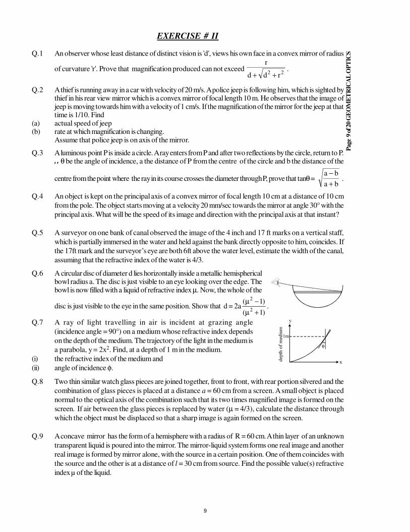
Page
9 o
f 20 G
EO
ME
TR
ICA
L O
PT
ICS
EXERCISE # II
Q.1 An observer whose least distance of distinct vision is 'd', views his own face in a convex mirror of radius
of curvature 'r'. Prove that magnification produced can not exceed 22 rdd
r
++.
Q.2 A thief is running away in a car with velocity of 20 m/s. A police jeep is following him, which is sighted bythief in his rear view mirror which is a convex mirror of focal length 10 m. He observes that the image ofjeep is moving towards him with a velocity of 1 cm/s. If the magnification of the mirror for the jeep at thattime is 1/10. Find
(a) actual speed of jeep(b) rate at which magnification is changing.
Assume that police jeep is on axis of the mirror.
Q.3 A luminous point P is inside a circle. A ray enters from P and after two reflections by the circle, return to P.I fI fI fI f θ be the angle of incidence, a the distance of P from the centre of the circle and b the distance of the
centre from the point where the ray in its course crosses the diameter through P, prove that tanθ = ba
ba
+−
.
Q.4 An object is kept on the principal axis of a convex mirror of focal length 10 cm at a distance of 10 cm
from the pole. The object starts moving at a velocity 20 mm/sec towards the mirror at angle 30° with the
principal axis. What will be the speed of its image and direction with the principal axis at that instant?
Q.5 A surveyor on one bank of canal observed the image of the 4 inch and 17 ft marks on a vertical staff,
which is partially immersed in the water and held against the bank directly opposite to him, coincides. If
the 17ft mark and the surveyor’s eye are both 6ft above the water level, estimate the width of the canal,
assuming that the refractive index of the water is 4/3.
Q.6 A circular disc of diameter d lies horizontally inside a metallic hemisphericalbowl radius a. The disc is just visible to an eye looking over the edge. Thebowl is now filled with a liquid of refractive index µ. Now, the whole of the
disc is just visible to the eye in the same position. Show that d = 2a)1(
)1(2
2
+µ
−µ.
Q.7 A ray of light travelling in air is incident at grazing angle
(incidence angle = 90°) on a medium whose refractive index depends
on the depth of the medium. The trajectory of the light in the medium is
a parabola, y = 2x2. Find, at a depth of 1 m in the medium.
(i) the refractive index of the medium and
(ii) angle of incidence φ.
Q.8 Two thin similar watch glass pieces are joined together, front to front, with rear portion silvered and the
combination of glass pieces is placed at a distance a = 60 cm from a screen. A small object is placed
normal to the optical axis of the combination such that its two times magnified image is formed on the
screen. If air between the glass pieces is replaced by water (µ = 4/3), calculate the distance through
which the object must be displaced so that a sharp image is again formed on the screen.
Q.9 A concave mirror has the form of a hemisphere with a radius of R = 60 cm. A thin layer of an unknown
transparent liquid is poured into the mirror. The mirror-liquid system forms one real image and another
real image is formed by mirror alone, with the source in a certain position. One of them coincides with
the source and the other is at a distance of l = 30 cm from source. Find the possible value(s) refractive
index µ of the liquid.
9
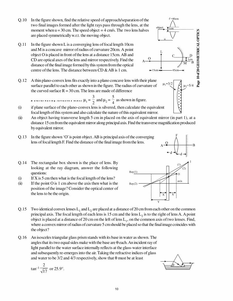
Page
10 o
f 20 G
EO
ME
TR
ICA
L O
PT
ICS
Q.10 In the figure shown, find the relative speed of approach/separation of the
two final images formed after the light rays pass through the lens, at the
moment when u = 30 cm. The speed object = 4 cm/s. The two lens halves
are placed symmetrically w.r.t. the moving object.
Q.11 In the figure shown L is a converging lens of focal length 10cm
and M is a concave mirror of radius of curvature 20cm. A point
object O is placed in front of the lens at a distance 15cm. AB and
CD are optical axes of the lens and mirror respectively. Find the
distance of the final image formed by this system from the optical
centre of the lens. The distance between CD & AB is 1 cm.
Q.12 A thin plano-convex lens fits exactly into a plano concave lens with their plane
surface parallel to each other as shown in the figure. The radius of curvature of
the curved surface R = 30 cm. The lens are made of difference
m a t e r i a l h a v i n g r e f r a c t i v e i n d e xm a t e r i a l h a v i n g r e f r a c t i v e i n d e xm a t e r i a l h a v i n g r e f r a c t i v e i n d e xm a t e r i a l h a v i n g r e f r a c t i v e i n d e x µ1 =
2
3 and µ
2 =
4
5 as shown in figure.
(i) if plane surface of the plano-convex lens is silvered, then calculate the equivalent
focal length of this system and also calculate the nature of this equivalent mirror.
(ii) An object having transverse length 5 cm in placed on the axis of equivalent mirror (in part 1), at a
distance 15 cm from the equivalent mirror along principal axis. Find the transverse magnification produced
by equivalent mirror.
Q.13 In the figure shown ‘O’ is point object. AB is principal axis of the converging
lens of focal length F. Find the distance of the final image from the lens.
Q.14 The rectangular box shown is the place of lens. By
looking at the ray diagram, answer the following
questions:
(i) If X is 5 cm then what is the focal length of the lens?
(ii) If the point O is 1 cm above the axis then what is the
position of the image? Consider the optical center of
the lens to be the origin.
Q.15 Two identical convex lenses L1 and L
2 are placed at a distance of 20 cm from each other on the common
principal axis. The focal length of each lens is 15 cm and the lens L2 is to the right of lens A. A point
object is placed at a distance of 20 cm on the left of lens L1, on the common axis of two lenses. Find,
where a convex mirror of radius of curvature 5 cm should be placed so that the final image coincides with
the object?
Q.16 An isosceles triangular glass prism stands with its base in water as shown. The
angles that its two equal sides make with the base are θ each. An incident ray of
light parallel to the water surface internally reflects at the glass-water interface
and subsequently re-emerges into the air. Taking the refractive indices of glass
and water to be 3/2 and 4/3 respectively, show that θ must be at least
tan–1
17
2 or 25.9°.
10
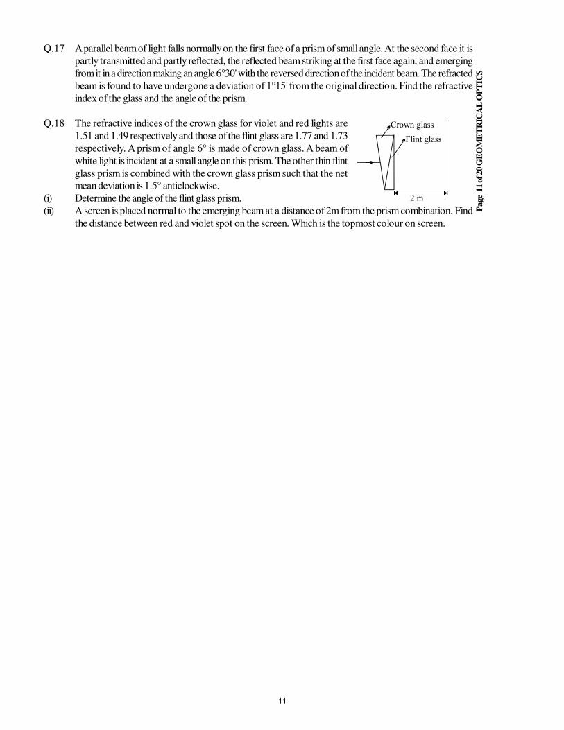
Page
11 o
f 20 G
EO
ME
TR
ICA
L O
PT
ICS
Q.17 A parallel beam of light falls normally on the first face of a prism of small angle. At the second face it is
partly transmitted and partly reflected, the reflected beam striking at the first face again, and emerging
from it in a direction making an angle 6°30' with the reversed direction of the incident beam. The refracted
beam is found to have undergone a deviation of 1°15' from the original direction. Find the refractive
index of the glass and the angle of the prism.
Q.18 The refractive indices of the crown glass for violet and red lights are
1.51 and 1.49 respectively and those of the flint glass are 1.77 and 1.73
respectively. A prism of angle 6° is made of crown glass. A beam of
white light is incident at a small angle on this prism. The other thin flint
glass prism is combined with the crown glass prism such that the net
mean deviation is 1.5° anticlockwise.
(i) Determine the angle of the flint glass prism.
(ii) A screen is placed normal to the emerging beam at a distance of 2m from the prism combination. Find
the distance between red and violet spot on the screen. Which is the topmost colour on screen.
11
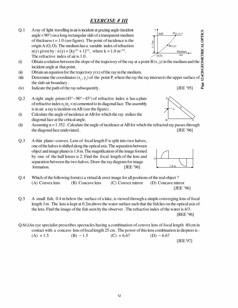
Page
12 o
f 20 G
EO
ME
TR
ICA
L O
PT
ICS
EXERCISE # III
Q.1 A ray of light travelling in air is incident at grazing angle (incident
angle = 90°) on a long rectangular slab of a transparent medium
of thickness t = 1.0 (see figure). The point of incidence is the
origin A (O, O). The medium has a variable index of refraction
n(y) given by : n (y) = [ky3/2 + 1]1/2, where k = 1.0 m−3/2 .
The refractive index of air is 1.0 .
(i) Obtain a relation between the slope of the trajectory of the ray at a point B (x , y) in the medium and the
incident angle at that point.
(ii) Obtain an equation for the trajectory y (x) of the ray in the medium.
(iii) Determine the coordinates (x1 , y
1) of the point P, where the ray the ray intersects the upper surface of
the slab-air boundary .
(iv) Indicate the path of the ray subsequently . [JEE ’95]
Q.2 A right angle prism (45° − 90° − 45°) of refractive index n has a plate
of refractive index n1
(n1 < n) cemented to its diagonal face. The assembly
is in air. a ray is incident on AB (see the figure) .
(i) Calculate the angle of incidence at AB for which the ray strikes the
diagonal face at the critical angle.
(ii) Assuming n = 1.352 . Calculate the angle of incidence at AB for which the refracted ray passes through
the diagonal face undeviated . [JEE ’96]
Q.3 A thin plano−convex. Lens of focal length F is split into two halves,
one of the halves is shifted along the optical axis. The separation between
object and image planes is 1.8 m. The magnification of the image formed
by one of the half lenses is 2. Find the focal length of the lens and
separation between the two halves. Draw the ray diagram for image
formation. [JEE ’96]
Q.4 Which of the following form(s) a virtual & erect image for all positions of the real object ?
(A) Convex lens (B) Concave lens (C) Convex mirror (D) Concave mirror
[JEE ’96]
Q.5 A small fish, 0.4 m below the surface of a lake, is viewed through a simple converging lens of focal
length 3 m . The lens is kept at 0.2m above the water surface such that the fish lies on the optical axis of
the lens. Find the image of the fish seen by the observer . The refractive index of the water is 4/3.
[REE ’96]
Q.6(i)An eye specialist prescribes spectacles having a combination of convex lens of focal length 40 cm in
contact with a concave lens of focal length 25 cm . The power of this lens combination in diopters is :
(A) + 1.5 (B) − 1.5 (C) + 6.67 (D) − 6.67
[JEE '97]
12
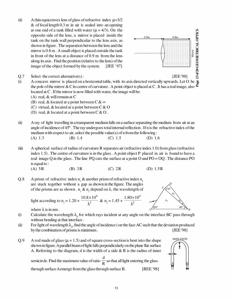
Page
13 o
f 20 G
EO
ME
TR
ICA
L O
PT
ICS
(ii) A thin equiconvex lens of glass of refractive index µ=3/2
& of focal length 0.3 m in air is sealed into an opening
at one end of a tank filled with water (µ = 4/3). On the
opposite side of the lens, a mirror is placed inside the
tank on the tank wall perpendicular to the lens axis, as
shown in figure . The separation between the lens and the
mirror is 0.8 m . A small object is placed outside the tank
in front of the lens at a distance of 0.9 m from the lens
along its axis . Find the position (relative to the lens) of the
image of the object formed by the system. [JEE ' 97]
Q.7 Select the correct alternative(s) : [JEE '98]
(i) A concave mirror is placed on a horizontal table, with its axis directed vertically upwards. Let O be
the pole of the mirror & C its centre of curvature . A point object is placed at C . It has a real image, also
located at C . If the mirror is now filled with water, the image will be:
(A) real, & will remain at C
(B) real, & located at a point between C & ∞(C) virtual, & located at a point between C & O
(D) real, & located at a point between C & O .
(ii) A ray of light travelling in a transparent medium falls on a surface separating the medium from air at an
angle of incidence of 45º . The ray undergoes total internal reflection . If n is the refractive index of the
medium with respect to air, select the possible value(s) of n from the following :
(A) 1.3 (B) 1.4 (C) 1.5 (D) 1.6
(iii) A spherical surface of radius of curvature R separates air (refractive index 1.0) from glass (refractive
index 1.5) . The centre of curvature is in the glass . A point object P placed in air is found to have a
real image Q in the glass . The line PQ cuts the surface at a point O and PO = OQ . The distance PO
is equal to :
(A) 5 R (B) 3 R (C) 2 R (D) 1.5 R
Q.8 A prism of refractive index n1 & another prism of refractive index n
2
are stuck together without a gap as shown in the figure. The angles
of the prisms are as shown . n1 & n
2 depend on λ, the wavelength of
light according to n1 = 1.20 + 2
4108.10
λ
×& n
2 = 1.45 + 2
41080.1
λ
×
where λ is in nm .
(i) Calculate the wavelength λ0 for which rays incident at any angle on the interface BC pass through
without bending at that interface .
(ii) For light of wavelength λ0, find the angle of incidence i on the face AC such that the deviation produced
by the combination of prisms is minimum . [JEE '98]
Q.9 A rod made of glass (µ = 1.5) and of square cross-section is bent into the shape
shown in figure. A parallel beam of light falls perpendicularly on the plane flat surface
A. Referring to the diagram, d is the width of a side & R is the radius of inner
semicircle. Find the maximum value of ratio R
dso that all light entering the glass
through surface A emerge from the glass through surface B. [REE '98]
13
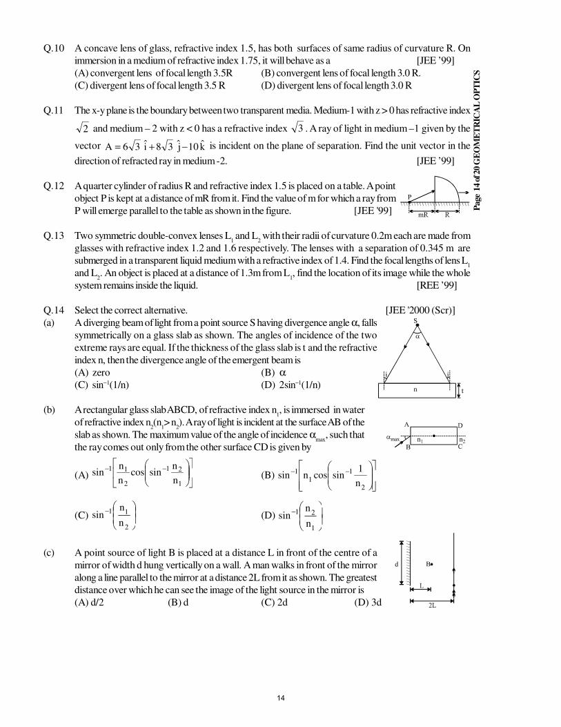
Page
14 o
f 20 G
EO
ME
TR
ICA
L O
PT
ICS
Q.10 A concave lens of glass, refractive index 1.5, has both surfaces of same radius of curvature R. On
immersion in a medium of refractive index 1.75, it will behave as a [JEE ’99]
(A) convergent lens of focal length 3.5R (B) convergent lens of focal length 3.0 R.
(C) divergent lens of focal length 3.5 R (D) divergent lens of focal length 3.0 R
Q.11 The x-y plane is the boundary between two transparent media. Medium-1 with z > 0 has refractive index
2 and medium – 2 with z < 0 has a refractive index 3 . A ray of light in medium –1 given by the
vector k10j38i36A −+= is incident on the plane of separation. Find the unit vector in the
direction of refracted ray in medium -2. [JEE ’99]
Q.12 A quarter cylinder of radius R and refractive index 1.5 is placed on a table. A point
object P is kept at a distance of mR from it. Find the value of m for which a ray from
P will emerge parallel to the table as shown in the figure. [JEE '99]
Q.13 Two symmetric double-convex lenses L1 and L
2 with their radii of curvature 0.2m each are made from
glasses with refractive index 1.2 and 1.6 respectively. The lenses with a separation of 0.345 m are
submerged in a transparent liquid medium with a refractive index of 1.4. Find the focal lengths of lens L1
and L2. An object is placed at a distance of 1.3m from L
1, find the location of its image while the whole
system remains inside the liquid. [REE ’99]
Q.14 Select the correct alternative. [JEE '2000 (Scr)]
(a) A diverging beam of light from a point source S having divergence angle α, falls
symmetrically on a glass slab as shown. The angles of incidence of the two
extreme rays are equal. If the thickness of the glass slab is t and the refractive
index n, then the divergence angle of the emergent beam is
(A) zero (B) α(C) sin−1(1/n) (D) 2sin−1(1/n)
(b) A rectangular glass slab ABCD, of refractive index n1, is immersed in water
of refractive index n2(n
1> n
2). A ray of light is incident at the surface AB of the
slab as shown. The maximum value of the angle of incidence αmax
, such that
the ray comes out only from the other surface CD is given by
(A)
−−
1
21
2
11
n
nsincos
n
nsin (B)
−−
2
11
1
n
1sincosnsin
(C)
−
2
11
n
nsin (D)
−
1
21
n
nsin
(c) A point source of light B is placed at a distance L in front of the centre of a
mirror of width d hung vertically on a wall. A man walks in front of the mirror
along a line parallel to the mirror at a distance 2L from it as shown. The greatest
distance over which he can see the image of the light source in the mirror is
(A) d/2 (B) d (C) 2d (D) 3d
14
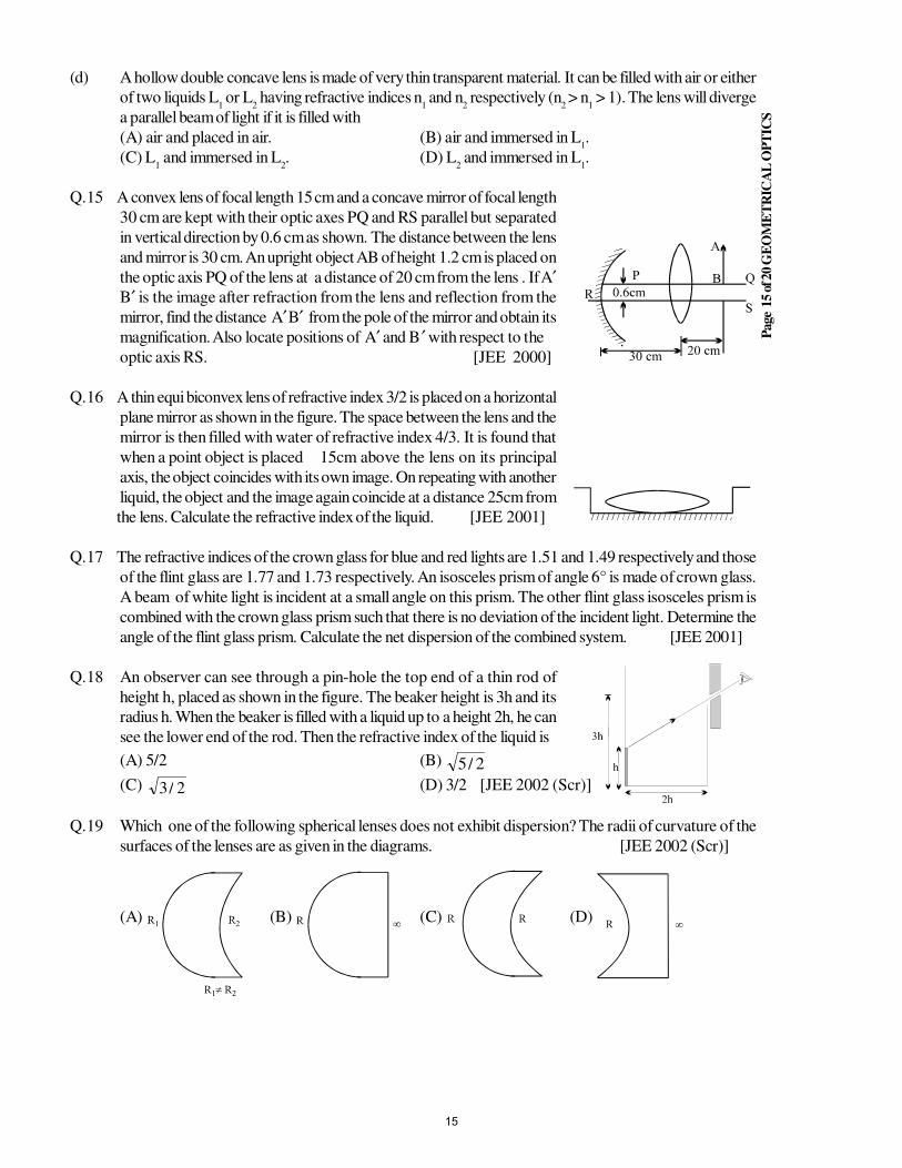
Page
15 o
f 20 G
EO
ME
TR
ICA
L O
PT
ICS
(d) A hollow double concave lens is made of very thin transparent material. It can be filled with air or either
of two liquids L1 or L
2 having refractive indices n
1 and n
2 respectively (n
2 > n
1 > 1). The lens will diverge
a parallel beam of light if it is filled with
(A) air and placed in air. (B) air and immersed in L1.
(C) L1 and immersed in L
2. (D) L
2 and immersed in L
1.
Q.15 A convex lens of focal length 15 cm and a concave mirror of focal length
30 cm are kept with their optic axes PQ and RS parallel but separated
in vertical direction by 0.6 cm as shown. The distance between the lens
and mirror is 30 cm. An upright object AB of height 1.2 cm is placed on
the optic axis PQ of the lens at a distance of 20 cm from the lens . If A′B′ is the image after refraction from the lens and reflection from the
mirror, find the distance A′ B′ from the pole of the mirror and obtain its
magnification. Also locate positions of A′ and B ′ with respect to the
optic axis RS. [JEE 2000]
Q.16 A thin equi biconvex lens of refractive index 3/2 is placed on a horizontal
plane mirror as shown in the figure. The space between the lens and the
mirror is then filled with water of refractive index 4/3. It is found that
when a point object is placed 15cm above the lens on its principal
axis, the object coincides with its own image. On repeating with another
liquid, the object and the image again coincide at a distance 25cm from
the lens. Calculate the refractive index of the liquid. [JEE 2001]
Q.17 The refractive indices of the crown glass for blue and red lights are 1.51 and 1.49 respectively and those
of the flint glass are 1.77 and 1.73 respectively. An isosceles prism of angle 6° is made of crown glass.
A beam of white light is incident at a small angle on this prism. The other flint glass isosceles prism is
combined with the crown glass prism such that there is no deviation of the incident light. Determine the
angle of the flint glass prism. Calculate the net dispersion of the combined system. [JEE 2001]
Q.18 An observer can see through a pin-hole the top end of a thin rod of
height h, placed as shown in the figure. The beaker height is 3h and its
radius h. When the beaker is filled with a liquid up to a height 2h, he can
see the lower end of the rod. Then the refractive index of the liquid is
(A) 5/2 (B) 2/5
(C) 2/3 (D) 3/2 [JEE 2002 (Scr)]
Q.19 Which one of the following spherical lenses does not exhibit dispersion? The radii of curvature of the
surfaces of the lenses are as given in the diagrams. [JEE 2002 (Scr)]
(A) (B) (C) (D)
15
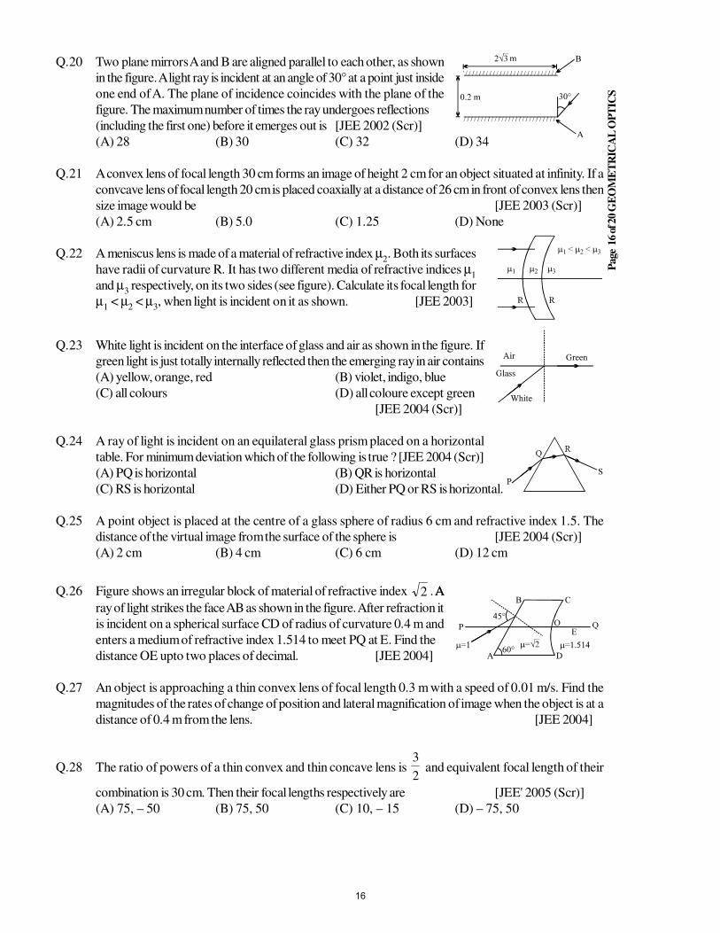
Page
16 o
f 20 G
EO
ME
TR
ICA
L O
PT
ICS
Q.20 Two plane mirrors A and B are aligned parallel to each other, as shown
in the figure. A light ray is incident at an angle of 30° at a point just inside
one end of A. The plane of incidence coincides with the plane of the
figure. The maximum number of times the ray undergoes reflections
(including the first one) before it emerges out is [JEE 2002 (Scr)]
(A) 28 (B) 30 (C) 32 (D) 34
Q.21 A convex lens of focal length 30 cm forms an image of height 2 cm for an object situated at infinity. If a
convcave lens of focal length 20 cm is placed coaxially at a distance of 26 cm in front of convex lens then
size image would be [JEE 2003 (Scr)]
(A) 2.5 cm (B) 5.0 (C) 1.25 (D) None
Q.22 A meniscus lens is made of a material of refractive index µ2. Both its surfaces
have radii of curvature R. It has two different media of refractive indices µ1
and µ3 respectively, on its two sides (see figure). Calculate its focal length for
µ1 < µ
2 < µ
3, when light is incident on it as shown. [JEE 2003]
Q.23 White light is incident on the interface of glass and air as shown in the figure. If
green light is just totally internally reflected then the emerging ray in air contains
(A) yellow, orange, red (B) violet, indigo, blue
(C) all colours (D) all coloure except green
[JEE 2004 (Scr)]
Q.24 A ray of light is incident on an equilateral glass prism placed on a horizontal
table. For minimum deviation which of the following is true ? [JEE 2004 (Scr)]
(A) PQ is horizontal (B) QR is horizontal
(C) RS is horizontal (D) Either PQ or RS is horizontal.
Q.25 A point object is placed at the centre of a glass sphere of radius 6 cm and refractive index 1.5. The
distance of the virtual image from the surface of the sphere is [JEE 2004 (Scr)]
(A) 2 cm (B) 4 cm (C) 6 cm (D) 12 cm
Q.26 Figure shows an irregular block of material of refractive index 2 . AA
ray of light strikes the face AB as shown in the figure. After refraction it
is incident on a spherical surface CD of radius of curvature 0.4 m and
enters a medium of refractive index 1.514 to meet PQ at E. Find the
distance OE upto two places of decimal. [JEE 2004]
Q.27 An object is approaching a thin convex lens of focal length 0.3 m with a speed of 0.01 m/s. Find the
magnitudes of the rates of change of position and lateral magnification of image when the object is at a
distance of 0.4 m from the lens. [JEE 2004]
Q.28 The ratio of powers of a thin convex and thin concave lens is 2
3 and equivalent focal length of their
combination is 30 cm. Then their focal lengths respectively are [JEE' 2005 (Scr)]
(A) 75, – 50 (B) 75, 50 (C) 10, – 15 (D) – 75, 50
16
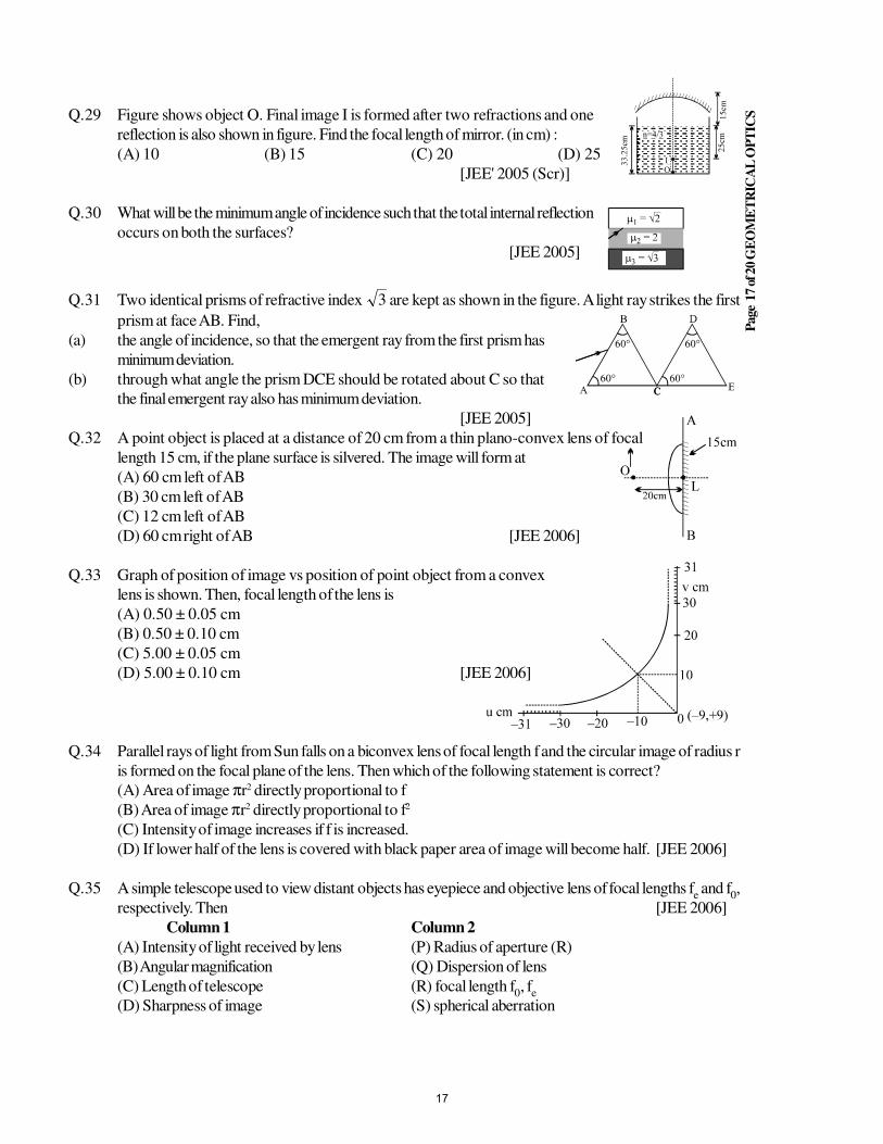
Page
17 o
f 20 G
EO
ME
TR
ICA
L O
PT
ICSQ.29 Figure shows object O. Final image I is formed after two refractions and one
reflection is also shown in figure. Find the focal length of mirror. (in cm) :
(A) 10 (B) 15 (C) 20 (D) 25
[JEE' 2005 (Scr)]
Q.30 What will be the minimum angle of incidence such that the total internal reflection
occurs on both the surfaces?
[JEE 2005]
Q.31 Two identical prisms of refractive index 3 are kept as shown in the figure. A light ray strikes the first
prism at face AB. Find,
(a) the angle of incidence, so that the emergent ray from the first prism has
minimum deviation.
(b) through what angle the prism DCE should be rotated about C so that
the final emergent ray also has minimum deviation.
[JEE 2005]
Q.32 A point object is placed at a distance of 20 cm from a thin plano-convex lens of focal
length 15 cm, if the plane surface is silvered. The image will form at
(A) 60 cm left of AB
(B) 30 cm left of AB
(C) 12 cm left of AB
(D) 60 cm right of AB [JEE 2006]
Q.33 Graph of position of image vs position of point object from a convex
lens is shown. Then, focal length of the lens is
(A) 0.50 ± 0.05 cm
(B) 0.50 ± 0.10 cm
(C) 5.00 ± 0.05 cm
(D) 5.00 ± 0.10 cm [JEE 2006]
Q.34 Parallel rays of light from Sun falls on a biconvex lens of focal length f and the circular image of radius r
is formed on the focal plane of the lens. Then which of the following statement is correct?
(A) Area of image πr2 directly proportional to f
(B) Area of image πr2 directly proportional to f2
(C) Intensity of image increases if f is increased.
(D) If lower half of the lens is covered with black paper area of image will become half. [JEE 2006]
Q.35 A simple telescope used to view distant objects has eyepiece and objective lens of focal lengths fe and f
0,
respectively. Then [JEE 2006]
Column 1 Column 2
(A) Intensity of light received by lens (P) Radius of aperture (R)
(B) Angular magnification (Q) Dispersion of lens
(C) Length of telescope (R) focal length f0, f
e
(D) Sharpness of image (S) spherical aberration
17
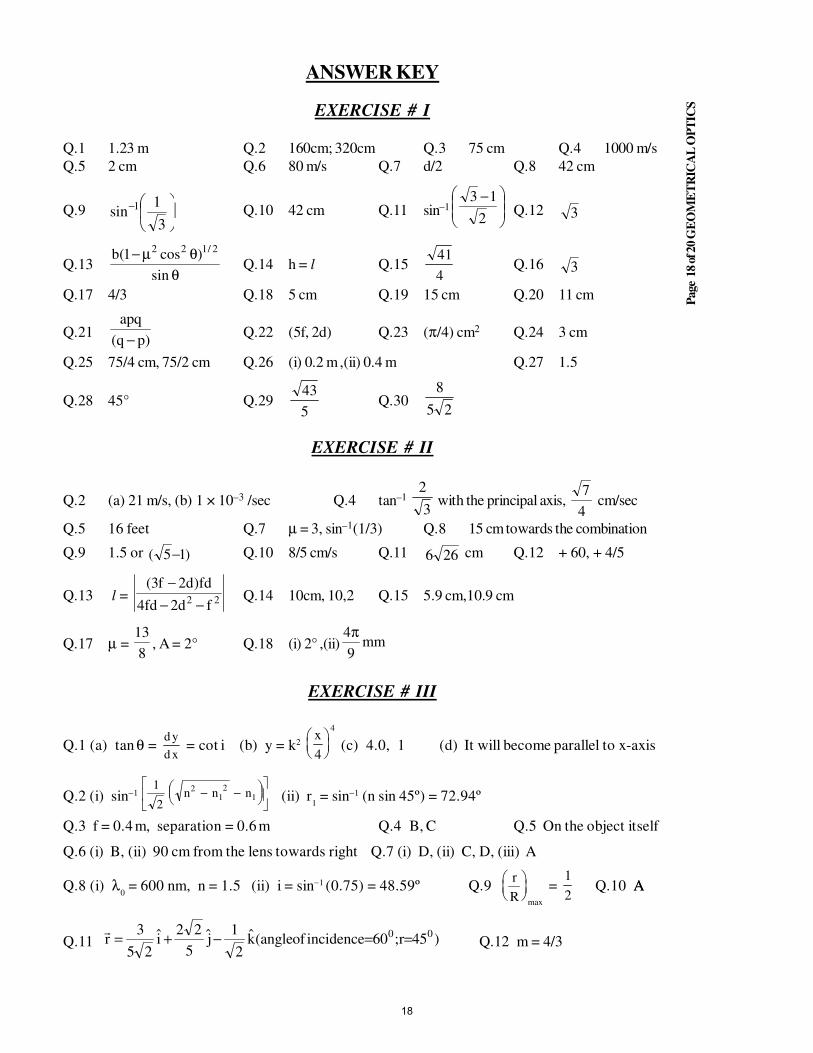
Page
18 o
f 20 G
EO
ME
TR
ICA
L O
PT
ICS
ANSWER KEY
EXERCISE # I
Q.1 1.23 m Q.2 160cm; 320cm Q.3 75 cm Q.4 1000 m/s
Q.5 2 cm Q.6 80 m/s Q.7 d/2 Q.8 42 cm
Q.9
−
3
1sin 1 Q.10 42 cm Q.11 sin–1
−
2
13Q.12 3
Q.13θ
θµ−sin
)cos1(b 2/122
Q.14 h = l Q.154
41Q.16 3
Q.17 4/3 Q.18 5 cm Q.19 15 cm Q.20 11 cm
Q.21)pq(
apq
− Q.22 (5f, 2d) Q.23 (π/4) cm2 Q.24 3 cm
Q.25 75/4 cm, 75/2 cm Q.26 (i) 0.2 m ,(ii) 0.4 m Q.27 1.5
Q.28 45° Q.295
43Q.30
25
8
EXERCISE # II
Q.2 (a) 21 m/s, (b) 1 × 10⁻³ /sec Q.4 tan–1 3
2 with the principal axis,
4
7 cm/sec
Q.5 16 feet Q.7 µ = 3, sin–1(1/3) Q.8 15 cm towards the combination
Q.9 1.5 or )15( − Q.10 8/5 cm/s Q.11 266 cm Q.12 + 60, + 4/5
Q.13 l = 22 fd2fd4
fd)d2f3(
−−
−Q.14 10cm, 10,2 Q.15 5.9 cm,10.9 cm
Q.17 µ = 8
13, A = 2° Q.18 (i) 2° ,(ii) mm
9
4π
EXERCISE # III
Q.1 (a) tan θ = d y
d x = cot i (b) y = k2
x
4
4
(c) 4.0, 1 (d) It will become parallel to x-axis
Q.2 (i) sin−1 1
2
212
1n n n− −
(ii) r
1 = sin−1 (n sin 45º) = 72.94º
Q.3 f = 0.4 m, separation = 0.6 m Q.4 B, C Q.5 On the object itself
Q.6 (i) B, (ii) 90 cm from the lens towards right Q.7 (i) D, (ii) C, D, (iii) A
Q.8 (i) λ0 = 600 nm, n = 1.5 (ii) i = sin−1 (0.75) = 48.59º Q.9
r
R
max
= 1
2 Q.10 AA
Q.11 )45r;60incidenceofangle(k2
1j
5
22i
25
3r 00 ==−+=
Q.12 m = 4/3
18
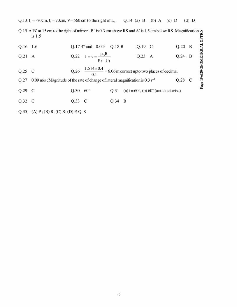
Page
19 o
f 20 G
EO
ME
TR
ICA
L O
PT
ICS
Q.13 f1 = -70cm, f
2 = 70cm, V= 560 cm to the right of L
2Q.14 (a) B (b) A (c) D (d) D
Q.15 A′ B′ at 15 cm to the right of mirror . B′ is 0.3 cm above RS and A′ is 1.5 cm below RS. Magnification
is 1.5
Q.16 1.6 Q.17 40 and –0.040 Q.18 B Q.19 C Q.20 B
Q.21 A Q.2213
3Rvf
µ−µµ
== Q.23 A Q.24 B
Q.25 C Q.26 06.61.0
4.0514.1=
×m correct upto two places of decimal.
Q.27 0.09 m/s ; Magnitude of the rate of change of lateral magnification is 0.3 s–1. Q.28 C
Q.29 C Q.30 60° Q.31 (a) i = 60°, (b) 60° (anticlockwise)
Q.32 C Q.33 C Q.34 B
Q.35 (A) P ; (B) R; (C) R; (D) P, Q, S
19

STUDY PACKAGE
Target: IIT-JEE (Advanced)
SUBJECT: PHYSICS
TOPIC: XII P8. Optical Instruments
Index:
1. Key Concepts
2. Exercise I
3. Exercise II
4. Exercise III
5. Exercise IV
6. Answer Key
7. 34 Yrs. Que. from IIT-JEE
8. 10 Yrs. Que. from AIEEE
1
Page
2
of 8
O
PT
ICA
L I
NS
TR
UM
EN
TS
EXERCISE–I
Q.1 A distant object is viewed with a relaxed eye with the help of a small Galilean telescope having an
objective of focal length 15 cm and an eye piece of focal length 3 cm
(A) The distance between the objective and the eyepiece lens is 12 cm.
(B) The angular magnification of object is 5
(C) Image of the object is erect
(D) The distance between objective and eye piece lens is 18 cm
Q.2 A microscope consists of an objective with a focal length 2 mm and an eye piece with a focal length
40 mm. The distance between the foci (which are between the lenses) of objective and eyepiece is
18 cm. The total magnification of the microscope is(Consider normal adjustment and take D = 25 cm)
(A) 562.5 (B) 625 (C) 265 (D) 62.5
Q.3 A distant object is viewed with a relaxed eye with the help of a small Galilean telescope having an
objective of focal length 12 cm and an eyepiece of focal length -3 cm.
(A) The distance between objective and eyepiece lens is 9 cm.
(B) The distance between objective and eyepiece lens is 15 cm.
(C) The image of the object is inverted
(D) The angular magnification of the object is + 4.
Q.4 A Galileo telescope has an objective of focal length 100 cm & magnifying power 50 . The distance
between the two lenses in normal adjustment will be
(A) 150 cm (B) 100 cm (C) 98 cm (D) 200 cm
Q.5 Which of the following statement(s) about a simple telescope (astronomical) is/are true
(A) the objective lens forms a real image.
(B) The eyepiece acts as a magnifying glass
(C) the focal length of the objective lens is short
(D) the final image is inverted
Q.6 The separation between the objective and the eye piece of a compound microscope can be adjusted
between 9.8 cm to 11.8 cm. Focal length of the objective and the eyepiece are 1.0cm and 6cm
respectively. Eyepiece is movable and image is always needed at 24 cm from the eye. D = 24cm. Find
the minimum and maximum magnification which can be produced by the microscope.
(A) the minimum magnification is 20 and corresponds to the separation 9.8cm between lenses.
(B) the minimum magnification is 20 and corresponds to the separation 11.8cm between lenses.
(C) the maximum magnification is 30 and corresponds to the separation 9.8cm between lenses.
(D) the maximum magnification is 30 and corresponds to the separation 11.8cm between lenses.
Q.7 An astronomical telescope has an eyepiece of focal-length 5 cm. If the angular magnification in normal
adjustment is 10, the distance between the objective and eyepiece in cm is
(A) 110 (B) 55 (C) 50 (D) 45
Q.8 The magnifying power of a telescope in normal adjustment can be increased
(A) by increasing focal lengths of both lenses equally
(B) by fitting eyepiece of high power
(C) by fitting eyepiece of low power
(D) by increasing the distance of object
2
Page
3
of 8
O
PT
ICA
L I
NS
TR
UM
EN
TS
Q.9 A person with a defective sight is using a lens having a power of +2D. The lens he is using is
(A) concave lens with f = 0.5 m (B) convex lens with f = 2.0 m
(C) concave lens with f = 0.2 m (D) convex lens with f = 0.5 m
Q.10 In a compound microscope
(A) the object is held slightly beyond the focal point of the objective.
(B) the image formed by the objective is real.
(C) the image formed by the eye piece is virtual.
(D) none of the above
Q.11 An astronomical telescope has an angular magnification of magnitude 5 for distant objects. The separation
between the objective and the eyepiece is 36 cm. The Final image is formed at infinity. The focal length
fo of the objective and f
e of the eyepiece are
(A) 45 cm and – 9 cm respectively (B) 50 cm and 10 cm respectively
(C) 7.2 cm and 5 cm respectively (D) 30 cm and 6 cm respectively
Q.12 An astronomical telescope in normal adjustment receives light from a distant source S. The tube length is
now decreased slightly
(A) A virtual image of S will be formed at a finite distance.
(B) No image will be formed
(C) A small, real image of S will be formed behind the eyepiece, close to it.
(D) A large, real image of S will be formed behind the eyepiece, far away from it.
Q.13 In the previous question, if the tube length is increased slightly from its position of normal adjustment
(A) a virtual image of S will be formed at a finite distance
(B) no image will be formed
(C) a small, real image of S will be formed behind the eyepiece, close to it
(D) a large, real image of S will be formed behind the eyepiece, far away from it.
Q.14 In an astronomical telescope in normal adjustment, a straight black line of length L is drawn on the
objective lens. The eyepiece forms a real image of this line. The length of this image is l. The magnifying
power of the telescope is
(A) l
L(B)
l
L + 1 (C)
l
L– 1 (D)
1L
1L
−+
Q.15 An astronomical telescope and a Galilean telescope use identical objective lenses. They have the same
magnification, when both are in normal adjustment. The eyepiece of the astronomical telescope has a
focal length f.
(A) The tube lengths of the two telescope differ by f.
(B) The tube lengths of the two telescopes differ by 2f.
(C) The Galilean telescope has shorter tube length.
(D) the Galilean telescope has longer tube length.
Q.16 A single converging lens used as a simple microscope. In the position of maximum angular magnification,
(A) the object is placed at the focus of the lens
(B) the object is placed between the lens and its focus
(C) the image is formed at infinity
(D) the object and the image subtend the same angle at the eye.
3
Page
4
of 8
O
PT
ICA
L I
NS
TR
UM
EN
TS
Q.17 When an astronomical telescope is in normal adjustment, the magnification produced by it M. If this is
now turned around with the eyepiece facing a distant object and the eye placed close to the objective,
the magnification produced will be
(A) M
1(B)
1M
1
+(C)
1M
1
−(D)
1M
1M
+−
Q.18 In a simple microscope, if the final image is located at infinity then its magnifying power is
(A) 25/F (B) 25/D (C) F/25 (D) (1 + 25/F)
Q.19 When length of a microscope tube increases, its magnifying power
(A) decreases (B) increases
(C) does not change (D) may increases or decreases
Q.20 In a compound microscope, the intermediate image is
(A) virtual, erect and magnified (B) real, erect and magnified
(C) real, inverted and magnified (D) virtual, erect and reduced
Q.21 In a reflecting astronomical telescope, if the objective (a spherical mirror) is replaced by a parabolic
mirror of the same focal length and aperture, then
(A) The final image will be erect (B) The larger image will be obtained
(C) The telescope will gather more light (D) Spherical aberration will be absent
Q.22 A simple telescope, consisting of an objective of focal length 60 cm and a single eye lens of focal length
5 cm, is focused on a distant object in such a way that parallel rays emerge from the eye lens. If the
object subtends an angle of 2° at the objective, the angular width of the image is
(A) 10° (B) 24° (C) 50° (D) 1/6°
Q.23 A man wearing glasses of focal length + 1 m cannot clearly see beyond 1 m :
(A) if he is farsighted (B) if he is nearsighted
(C) if his vision is normal (D) in each of these cases.
Q.24 A man is looking at a small object placed at near point. Without altering the position of his eye or the
object, he puts a simple microscope of magnifying power 5X is normal adjustment before his eyes. the
angular magnification achieved is :
(A) 5 (B) 2.5 (C) 1 (D) can't see
4
Page
5
of 8
O
PT
ICA
L I
NS
TR
UM
EN
TS
EXERCISE–II
Q.1 The focal length of the objective of a microscope is Fo = 3 mm, of the eye- piece F
e = 5 cm. An object
is at a distance of a = 3.1 mm from the objective. Find the magnification of the microscope for a normal
eye, if the final image is 25 cm from the eye. Also find the separation of the lens.
Q.2 A telescope has an objective of focal length one meter and adjustable eyepiece. How much motion must
be given to the eye piece to focus an object lying between 5m and infinity. (Adjustment at ∞).
Q.3 An eye can distinguish between two points of an object if they are separated by more than 0.22 mm
when the object is placed at 25 cm from the eye .The object is now seen by a compound microscope
having 20 D objective and 10 D eyepiece separated by a distance of 20 cm. The final image is formed
at 25 cm from the eye. What is the minimum separation between two points d of the objects which can
now be distinguished.
Q.4 The objective of an astronomical telescope consists of
two thin lenses in contact, of focal lengths +20 cm and
– 25 cm respectively. Eyepiece of the same telescope
consists of two plano convex lenses each of focal length
f separated by 2/3 f as shown in the figure. Find the
value of l for which final image will be formed at
infinity with its angular magnification 100/3. Also find f.
Q.5 A Galilean telescope of angular magnification 10 has the length of 45 cm when adjusted to infinity. The
focal length objective is ______ & that of ocular is ______ .
Q.6 A compound microscope is used to enlarge an object kept at a distance 0.03 m from its objective which
consists of several convex lenses in contact and has focal length 0.02 m. If a lens of focal length 0.1 m is
removed from the objective, find out the distance by which the eyepiece of the microscope must be
moved to refocus the image.
Q.7 The focal lengths of the objective and the eyepiece of a compound microscope are 2.0 cm and 3.0 cm
respectively. The distance between the objective and the eyepiece is 15.0 cm. The final image formed by
the eyepiece is at infinity. Find the distance of object and image produced by the objective, from the
objective lens.
Q.8 In a compound microscope the objective and the eyepiece have focal lengths of 0.95 cm and 5 cm
respectively, and are kept at a distance of 20 cm. The last image is formed at a distance of 25 cm from
the eyepiece. Calculate the position of object and the total magnification.
Q.9 A Galilean telescope consists of an objective of focal length 12 cm and eyepiece of focal length 4 cm.
What should be the separation of the two lenses when the virtual image of a distant object is formed at
a distance of 24 cm from the eyepiece? What is the magnifying power of telescope under this condition?
Q.10 If the focal length of the objective and eyepiece of a microscope are 2 cm and 5 cm respectively and the
distance between them is 20 cm, what is the distance of the object from the objective when the image
seen by the eye is 25 cm from eyepiece? Also find the magnifying power.
Objective eyepiece
→→ l 2f/3→→
5
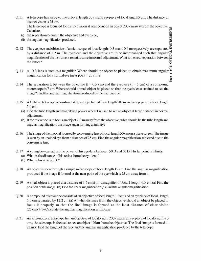
Page
6
of 8
O
PT
ICA
L I
NS
TR
UM
EN
TS
Q.11 A telescope has an objective of focal length 50 cm and eyepiece of focal length 5 cm. The distance of
distinct vision is 25 cm.
The telescope is focussed for distinct vision at near point on an object 200 cm away from the objective.
Calculate.
(i) the separation between the objective and eyepiece,
(ii) the angular magnification produced.
Q.12 The eyepiece and objective of a microscope, of focal lengths 0.3 m and 0.4 m respectively, are separated
by a distance of 1.2 m. The eyepiece and the objective are to be interchanged such that angular
magnification of the instrument remains same in normal adjustment. What is the new separation between
the lenses?
Q.13 A 10 D lens is sued as a magnifier. Where should the object be placed to obtain maximum angular
magnification for a normal eye (near point = 25 cm)?
Q.14 The separation L between the objective (f = 0.5 cm) and the eyepiece (f = 5 cm) of a compound
microscope is 7 cm. Where should a small object be placed so that the eye is least strained to see the
image? Find the angular magnification produced by the microscope.
Q.15 A Galilean telescope is constructed by an objective of focal length 50 cm and an eyepiece of focal length
5.0 cm.
(a) Find the tube length and magnifying power when it is used to see an object at large distance in normal
adjustment.
(b) If the telescope is to focus an object 2.0 m away from the objective, what should be the tube length and
angular magnification, the image again forming at infinity?
Q.16 The image of the moon if focused by a coverging lens of focal length 50 cm on a plane screen. The image
is seen by an unaided eye from a distance of 25 cm. Find the angular magnification achieved due to the
converging lens.
Q.17 A young boy can adjust the power of his eye-lens between 50 D and 60 D. His far point is infinity.
(a) What is the distance of his retina from the eye-lens ?
(b) What is his near point ?
Q.18 An object is seen through a simple microscope of focal length 12 cm. Find the angular magnification
produced if the image if formed at the near point of the eye which is 25 cm away from it.
Q.19 A small object is placed at a distance of 3.6 cm from a magnifier of focal l length 4.0 cm (a) Find the
position of the image. (b) Find the linear magnification (c) Find the angular magnification.
Q.20 A compound microscope consists of an objective of focal length 1.0 cm and an eyepiece of focal , length
5.0 cm separated by 12.2 cm (a) At what distance from the objective should an object be placed to
focus it properly so that the final image is formed at the least distance of clear vision
(25 cm) ? (b) Calculate the angular magnification in this case.
Q.21 An astronomical telescope has an objective of focal length 200 cm and an eyepiece of focal length 4.0
cm., the telescope is focused to see an object 10 km from the objective. The final image is formed at
infinity. Find the length of the tube and the angular magnification produced by the telescope.
6
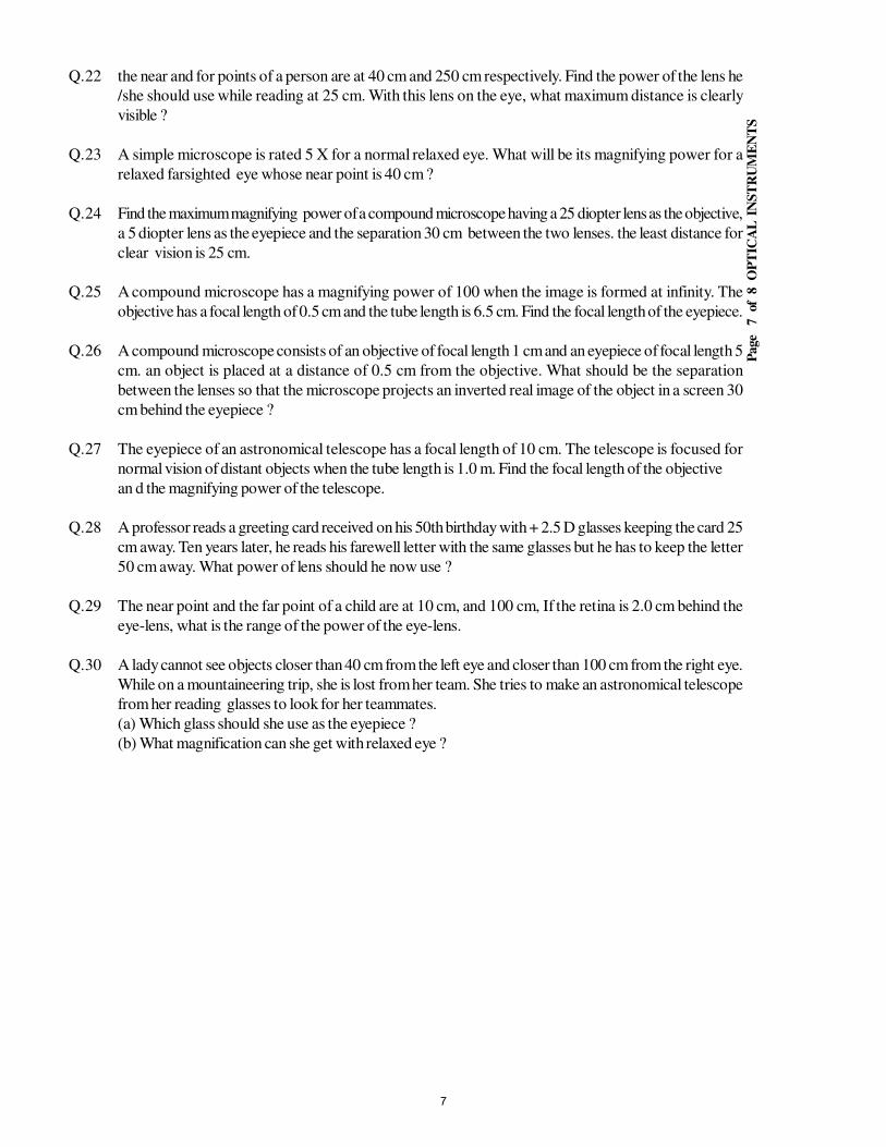
Page
7
of 8
O
PT
ICA
L I
NS
TR
UM
EN
TS
Q.22 the near and for points of a person are at 40 cm and 250 cm respectively. Find the power of the lens he
/she should use while reading at 25 cm. With this lens on the eye, what maximum distance is clearly
visible ?
Q.23 A simple microscope is rated 5 X for a normal relaxed eye. What will be its magnifying power for a
relaxed farsighted eye whose near point is 40 cm ?
Q.24 Find the maximum magnifying power of a compound microscope having a 25 diopter lens as the objective,
a 5 diopter lens as the eyepiece and the separation 30 cm between the two lenses. the least distance for
clear vision is 25 cm.
Q.25 A compound microscope has a magnifying power of 100 when the image is formed at infinity. The
objective has a focal length of 0.5 cm and the tube length is 6.5 cm. Find the focal length of the eyepiece.
Q.26 A compound microscope consists of an objective of focal length 1 cm and an eyepiece of focal length 5
cm. an object is placed at a distance of 0.5 cm from the objective. What should be the separation
between the lenses so that the microscope projects an inverted real image of the object in a screen 30
cm behind the eyepiece ?
Q.27 The eyepiece of an astronomical telescope has a focal length of 10 cm. The telescope is focused for
normal vision of distant objects when the tube length is 1.0 m. Find the focal length of the objective
an d the magnifying power of the telescope.
Q.28 A professor reads a greeting card received on his 50th birthday with + 2.5 D glasses keeping the card 25
cm away. Ten years later, he reads his farewell letter with the same glasses but he has to keep the letter
50 cm away. What power of lens should he now use ?
Q.29 The near point and the far point of a child are at 10 cm, and 100 cm, If the retina is 2.0 cm behind the
eye-lens, what is the range of the power of the eye-lens.
Q.30 A lady cannot see objects closer than 40 cm from the left eye and closer than 100 cm from the right eye.
While on a mountaineering trip, she is lost from her team. She tries to make an astronomical telescope
from her reading glasses to look for her teammates.
(a) Which glass should she use as the eyepiece ?
(b) What magnification can she get with relaxed eye ?
7
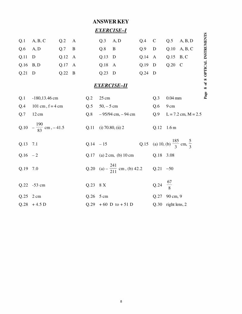
Page
8
of 8
O
PT
ICA
L I
NS
TR
UM
EN
TS
ANSWER KEY
EXERCISE–I
Q.1 A, B, C Q.2 A Q.3 A, D Q.4 C Q.5 A, B, D
Q.6 A, D Q.7 B Q.8 B Q.9 D Q.10 A, B, C
Q.11 D Q.12 A Q.13 D Q.14 A Q.15 B, C
Q.16 B, D Q.17 A Q.18 A Q.19 D Q.20 C
Q.21 D Q.22 B Q.23 D Q.24 D
EXERCISE–II
Q.1 -180,13.46 cm Q.2 25 cm Q.3 0.04 mm
Q.4 101 cm , f = 4 cm Q.5 50, – 5 cm Q.6 9 cm
Q.7 12 cm Q.8 – 95/94 cm, – 94 cm Q.9 L = 7.2 cm, M = 2.5
Q.10 – 83
190 cm , – 41.5 Q.11 (i) 70.80, (ii) 2 Q.12 1.6 m
Q.13 7.1 Q.14 – 15 Q.15 (a) 10, (b) 3
185 cm,
3
5
Q.16 – 2 Q.17 (a) 2 cm, (b) 10 cm Q.18 3.08
Q.19 7.0 Q.20 (a) – 211
241 cm , (b) 42.2 Q.21 −50
Q.22 -53 cm Q.23 8 X Q.248
67
Q.25 2 cm Q.26 5 cm Q.27 90 cm, 9
Q.28 + 4.5 D Q.29 + 60 D to + 51 D Q.30 right lens, 2
8

STUDY PACKAGE
Target: IIT-JEE (Advanced)
SUBJECT: PHYSICS
TOPIC: XII P9. Wave Optics
Index:
1. Key Concepts
2. Exercise I
3. Exercise II
4. Exercise III
5. Exercise IV
6. Answer Key
7. 34 Yrs. Que. from IIT-JEE
8. 10 Yrs. Que. from AIEEE
1
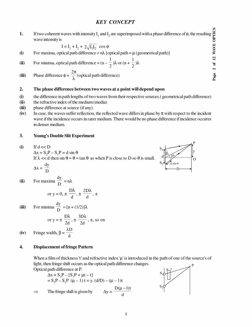
Pag
e
2
of
12
W
AV
E O
PT
ICS
KEY CONCEPT
1. If two coherent waves with intensity I1 and I
2 are superimposed with a phase difference of φ, the resulting
wave intensity is
I = I1 + I
2 +
21II2 cos φ(i) For maxima, optical path difference = nλ [optical path = µ (geometrical path)]
(ii) For minima, optical path difference = (n – 2
1)λ or (n +
2
1)λ
(iii) Phase difference φ = λπ2
(optical path difference)
2. The phase difference between two waves at a point will depend upon
(i) the difference in path lengths of two waves from their respective sources.( geometrical path difference)
(ii) the refractive index of the medium (media)
(iii) phase difference at source (if any).
(iv) In case, the waves suffer reflection, the reflected wave differs in phase by π with respect to the incident
wave if the incidence occurs in rarer medium. There would be no phase difference if incidence occures
in denser medium.
3. Young's Double Slit Experiment
(i) If d << D
∆x = S2P – S
1P = d sin θ
If λ << d then sin θ ≈ θ ≈ tan θ as when P is close to D so θ is small.
∆x = D
dy
(ii) For maxima D
dy = nλ
or y = 0, ± d
Dλ, ±
d
D2 λ, ±
(iii) For minima D
dy = [n + (1/2)]λ
or y = ± d2
Dλ, ±
d2
D3 λ, ±, so on
(iv) Fringe width, β = d
Dλ
4. Displacement of fringe Pattern
When a film of thickness 't' and refractive index 'µ' is introduced in the path of one of the source's of
light, then fringe shift occurs as the optical path difference changes.
Optical path difference at P.
∆x = S2P – [S
1P + µt – t]
= S2P – S
1P (µ – 1) t = y. (d/D) – (µ – 1)t
⇒ The fringe shift is given by ∆y =d
t)1(D −µ
2
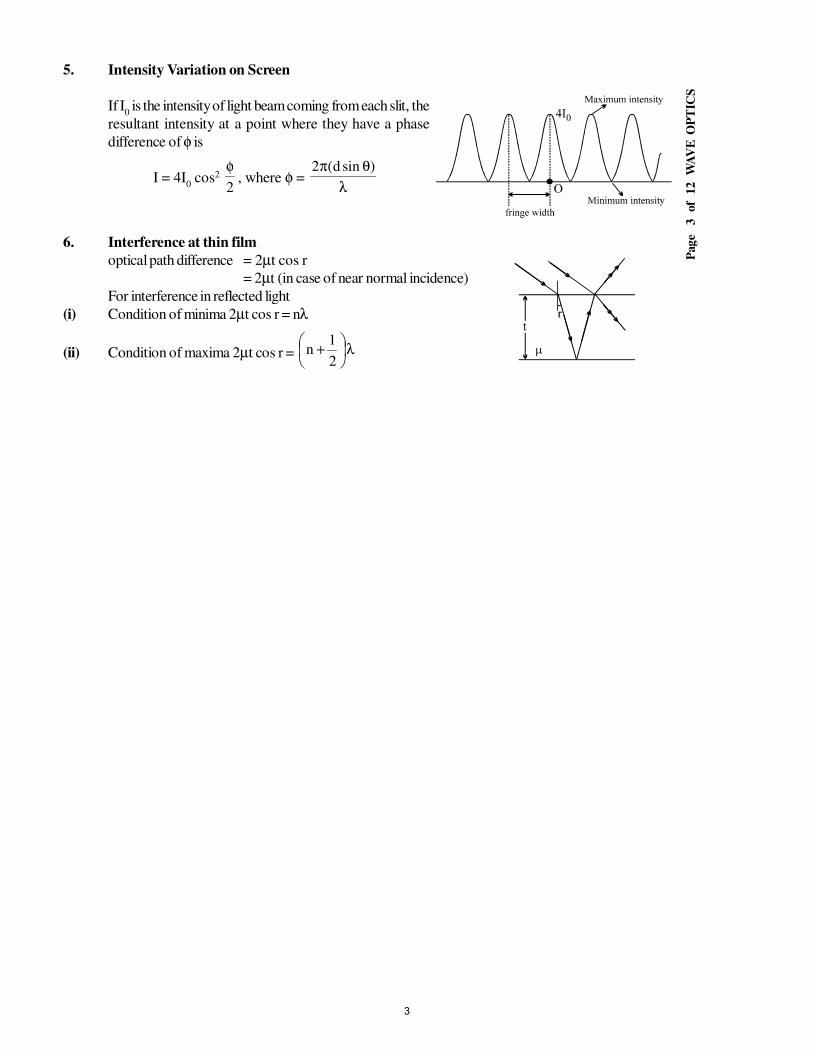
Pag
e
3
of
12
W
AV
E O
PT
ICS
5. Intensity Variation on Screen
If I0 is the intensity of light beam coming from each slit, the
resultant intensity at a point where they have a phase
difference of φ is
I = 4I0 cos2
2
φ, where φ =
λθπ )sind(2
6. Interference at thin film
optical path difference = 2µt cos r
= 2µt (in case of near normal incidence)
For interference in reflected light
(i) Condition of minima 2µt cos r = nλ
(ii) Condition of maxima 2µt cos r = λ
+2
1n
3
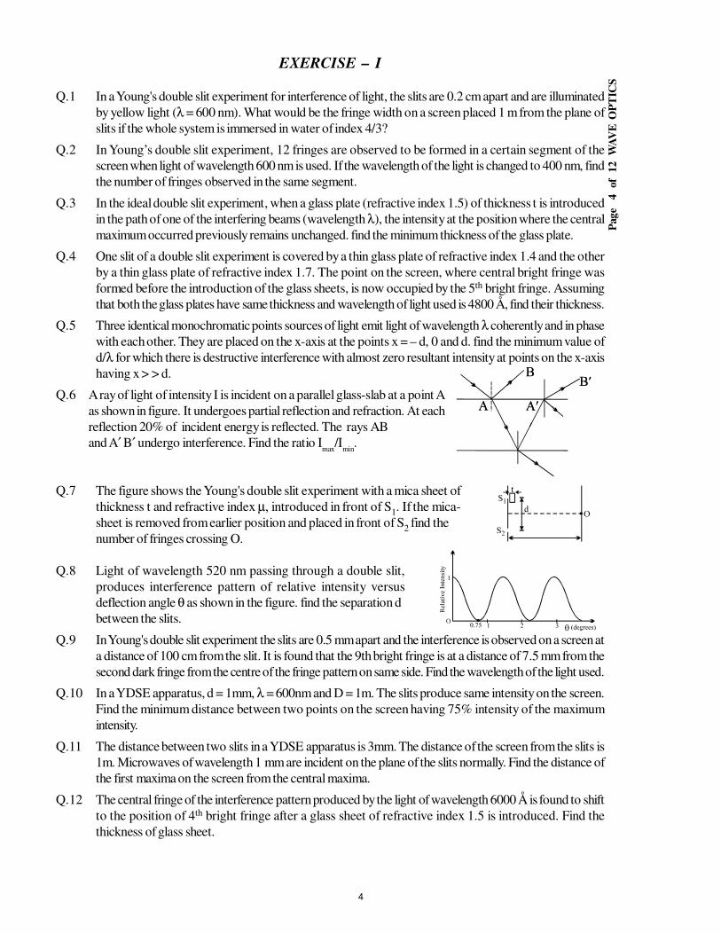
Pag
e
4
of
12
W
AV
E O
PT
ICS
EXERCISE – I
Q.1 In a Young's double slit experiment for interference of light, the slits are 0.2 cm apart and are illuminated
by yellow light (λ = 600 nm). What would be the fringe width on a screen placed 1 m from the plane of
slits if the whole system is immersed in water of index 4/3?
Q.2 In Young’s double slit experiment, 12 fringes are observed to be formed in a certain segment of the
screen when light of wavelength 600 nm is used. If the wavelength of the light is changed to 400 nm, find
the number of fringes observed in the same segment.
Q.3 In the ideal double slit experiment, when a glass plate (refractive index 1.5) of thickness t is introduced
in the path of one of the interfering beams (wavelength λ), the intensity at the position where the central
maximum occurred previously remains unchanged. find the minimum thickness of the glass plate.
Q.4 One slit of a double slit experiment is covered by a thin glass plate of refractive index 1.4 and the other
by a thin glass plate of refractive index 1.7. The point on the screen, where central bright fringe was
formed before the introduction of the glass sheets, is now occupied by the 5th bright fringe. Assuming
that both the glass plates have same thickness and wavelength of light used is 4800 Å, find their thickness.
Q.5 Three identical monochromatic points sources of light emit light of wavelength λ coherently and in phase
with each other. They are placed on the x-axis at the points x = – d, 0 and d. find the minimum value of
d/λ for which there is destructive interference with almost zero resultant intensity at points on the x-axis
having x > > d.
Q.6 A ray of light of intensity I is incident on a parallel glass-slab at a point A
as shown in figure. It undergoes partial reflection and refraction. At each
reflection 20% of incident energy is reflected. The rays AB
and A′ B′ undergo interference. Find the ratio Imax
/Imin
.
Q.7 The figure shows the Young's double slit experiment with a mica sheet of
thickness t and refractive index µ, introduced in front of S1. If the mica-
sheet is removed from earlier position and placed in front of S2 find the
number of fringes crossing O.
Q.8 Light of wavelength 520 nm passing through a double slit,
produces interference pattern of relative intensity versus
deflection angle θ as shown in the figure. find the separation d
between the slits.
Q.9 In Young's double slit experiment the slits are 0.5 mm apart and the interference is observed on a screen at
a distance of 100 cm from the slit. It is found that the 9th bright fringe is at a distance of 7.5 mm from the
second dark fringe from the centre of the fringe pattern on same side. Find the wavelength of the light used.
Q.10 In a YDSE apparatus, d = 1mm, λ = 600nm and D = 1m. The slits produce same intensity on the screen.
Find the minimum distance between two points on the screen having 75% intensity of the maximum
intensity.
Q.11 The distance between two slits in a YDSE apparatus is 3mm. The distance of the screen from the slits is
1m. Microwaves of wavelength 1 mm are incident on the plane of the slits normally. Find the distance of
the first maxima on the screen from the central maxima.
Q.12 The central fringe of the interference pattern produced by the light of wavelength 6000 Å is found to shift
to the position of 4th bright fringe after a glass sheet of refractive index 1.5 is introduced. Find the
thickness of glass sheet.
4
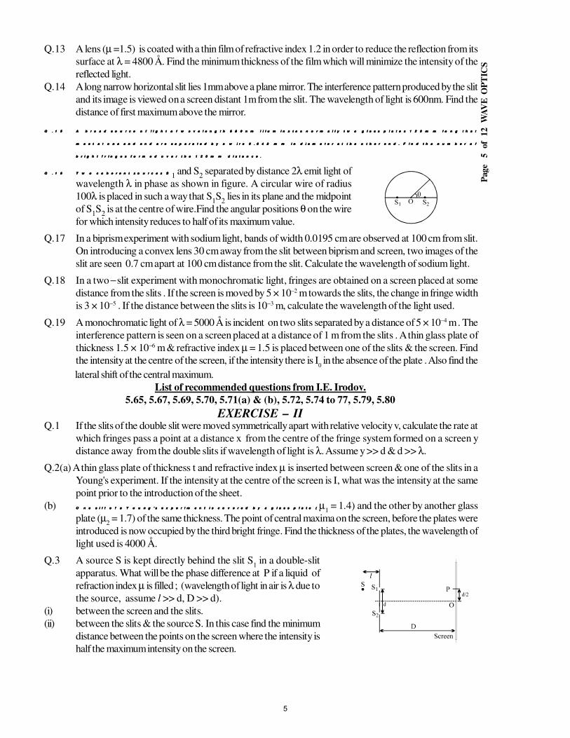
Pag
e
5
of
12
W
AV
E O
PT
ICS
Q.13 A lens (µ =1.5) is coated with a thin film of refractive index 1.2 in order to reduce the reflection from its
surface at λ = 4800 Å. Find the minimum thickness of the film which will minimize the intensity of the
reflected light.
Q.14 A long narrow horizontal slit lies 1mm above a plane mirror. The interference pattern produced by the slit
and its image is viewed on a screen distant 1m from the slit. The wavelength of light is 600nm. Find the
distance of first maximum above the mirror.
Q . 1 5Q . 1 5Q . 1 5Q . 1 5 A b r o a d s o u r c e o f l i g h t o f w a v e l e n g t h 6 8 0 n m i l l u m i n a t e s n o r m a l l y t w o g l a s s p l a t e s 1 2 0 m m l o n g t h a tA b r o a d s o u r c e o f l i g h t o f w a v e l e n g t h 6 8 0 n m i l l u m i n a t e s n o r m a l l y t w o g l a s s p l a t e s 1 2 0 m m l o n g t h a tA b r o a d s o u r c e o f l i g h t o f w a v e l e n g t h 6 8 0 n m i l l u m i n a t e s n o r m a l l y t w o g l a s s p l a t e s 1 2 0 m m l o n g t h a tA b r o a d s o u r c e o f l i g h t o f w a v e l e n g t h 6 8 0 n m i l l u m i n a t e s n o r m a l l y t w o g l a s s p l a t e s 1 2 0 m m l o n g t h a t
m e e t a t o n e e n d a n d a r e s e p a r a t e d b y a w i r e 0 . 0 4 8 m m i n d i a m e t e r a t t h e o t h e r e n d . F i n d t h e n u m b e r o fm e e t a t o n e e n d a n d a r e s e p a r a t e d b y a w i r e 0 . 0 4 8 m m i n d i a m e t e r a t t h e o t h e r e n d . F i n d t h e n u m b e r o fm e e t a t o n e e n d a n d a r e s e p a r a t e d b y a w i r e 0 . 0 4 8 m m i n d i a m e t e r a t t h e o t h e r e n d . F i n d t h e n u m b e r o fm e e t a t o n e e n d a n d a r e s e p a r a t e d b y a w i r e 0 . 0 4 8 m m i n d i a m e t e r a t t h e o t h e r e n d . F i n d t h e n u m b e r o f
b r i g h t f r i n g e s f o r m e d o v e r t h e 1 2 0 m m d i s t a n c e .b r i g h t f r i n g e s f o r m e d o v e r t h e 1 2 0 m m d i s t a n c e .b r i g h t f r i n g e s f o r m e d o v e r t h e 1 2 0 m m d i s t a n c e .b r i g h t f r i n g e s f o r m e d o v e r t h e 1 2 0 m m d i s t a n c e .
Q . 1 6Q . 1 6Q . 1 6Q . 1 6 T w o c o h e r e n t s o u r c e s ST w o c o h e r e n t s o u r c e s ST w o c o h e r e n t s o u r c e s ST w o c o h e r e n t s o u r c e s S1 and S
2 separated by distance 2λ emit light of
wavelength λ in phase as shown in figure. A circular wire of radius
100λ is placed in such a way that S1S
2 lies in its plane and the midpoint
of S1S
2 is at the centre of wire.Find the angular positions θ on the wire
for which intensity reduces to half of its maximum value.
Q.17 In a biprism experiment with sodium light, bands of width 0.0195 cm are observed at 100 cm from slit.
On introducing a convex lens 30 cm away from the slit between biprism and screen, two images of the
slit are seen 0.7 cm apart at 100 cm distance from the slit. Calculate the wavelength of sodium light.
Q.18 In a two − slit experiment with monochromatic light, fringes are obtained on a screen placed at some
distance from the slits . If the screen is moved by 5 × 10⁻² m towards the slits, the change in fringe width
is 3 × 10⁻⁵ . If the distance between the slits is 10−3 m, calculate the wavelength of the light used.
Q.19 A monochromatic light of λ = 5000 Å is incident on two slits separated by a distance of 5 × 10⁻⁴ m . The
interference pattern is seen on a screen placed at a distance of 1 m from the slits . A thin glass plate of
thickness 1.5 × 10⁻⁶ m & refractive index µ = 1.5 is placed between one of the slits & the screen. Find
the intensity at the centre of the screen, if the intensity there is I0 in the absence of the plate . Also find the
lateral shift of the central maximum.
List of recommended questions from I.E. Irodov.
5.65, 5.67, 5.69, 5.70, 5.71(a) & (b), 5.72, 5.74 to 77, 5.79, 5.80
EXERCISE – IIQ.1 If the slits of the double slit were moved symmetrically apart with relative velocity v, calculate the rate at
which fringes pass a point at a distance x from the centre of the fringe system formed on a screen y
distance away from the double slits if wavelength of light is λ. Assume y >> d & d >> λ.
Q.2(a) A thin glass plate of thickness t and refractive index µ is inserted between screen & one of the slits in a
Young's experiment. If the intensity at the centre of the screen is I, what was the intensity at the same
point prior to the introduction of the sheet.
(b) O n e s l i t o f a Y o u n g ' s e x p e r i m e n t i s c o v e r e d b y a g l a s s p l a t e (O n e s l i t o f a Y o u n g ' s e x p e r i m e n t i s c o v e r e d b y a g l a s s p l a t e (O n e s l i t o f a Y o u n g ' s e x p e r i m e n t i s c o v e r e d b y a g l a s s p l a t e (O n e s l i t o f a Y o u n g ' s e x p e r i m e n t i s c o v e r e d b y a g l a s s p l a t e ( µ1 = 1.4) and the other by another glass
plate (µ2 = 1.7) of the same thickness. The point of central maxima on the screen, before the plates were
introduced is now occupied by the third bright fringe. Find the thickness of the plates, the wavelength of
light used is 4000 Å.
Q.3 A source S is kept directly behind the slit S1 in a double-slit
apparatus. What will be the phase difference at P if a liquid of
refraction index µ is filled ; (wavelength of light in air is λ due to
the source, assume l >> d, D >> d).
(i) between the screen and the slits.
(ii) between the slits & the source S. In this case find the minimum
distance between the points on the screen where the intensity is
half the maximum intensity on the screen.
5
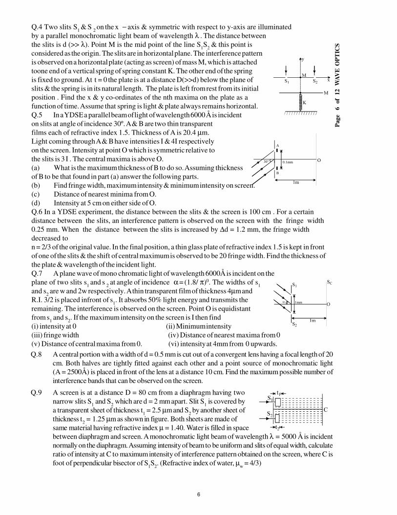
Pag
e
6
of
12
W
AV
E O
PT
ICS
Q.4 Two slits S1 & S
2 on the x − axis & symmetric with respect to y-axis are illuminated
by a parallel monochromatic light beam of wavelength λ . The distance between
the slits is d (>> λ). Point M is the mid point of the line S1S
2 & this point is
considered as the origin. The slits are in horizontal plane. The interference pattern
is observed on a horizontal plate (acting as screen) of mass M, which is attached
toone end of a vertical spring of spring constant K. The other end of the spring
is fixed to ground. At t = 0 the plate is at a distance D(>>d) below the plane of
slits & the spring is in its natural length. The plate is left from rest from its initial
position . Find the x & y co-ordinates of the nth maxima on the plate as a
function of time. Assume that spring is light & plate always remains horizontal.
Q.5 In a YDSE a parallel beam of light of wavelength 6000 Å is incident
on slits at angle of incidence 30º. A & B are two thin transparent
films each of refractive index 1.5. Thickness of A is 20.4 µm.
Light coming through A & B have intensities I & 4I respectively
on the screen. Intensity at point O which is symmetric relative to
the slits is 3 I . The central maxima is above O.
(a) What is the maximum thickness of B to do so. Assuming thickness
of B to be that found in part (a) answer the following parts.
(b) Find fringe width, maximum intensity & minimum intensity on screen.
(c) Distance of nearest minima from O.
(d) Intensity at 5 cm on either side of O.
Q.6 In a YDSE experiment, the distance between the slits & the screen is 100 cm . For a certain
distance between the slits, an interference pattern is observed on the screen with the fringe width
0.25 mm. When the distance between the slits is increased by ∆d = 1.2 mm, the fringe width
decreased to
n = 2/3 of the original value. In the final position, a thin glass plate of refractive index 1.5 is kept in front
of one of the slits & the shift of central maximum is observed to be 20 fringe width. Find the thickness of
the plate & wavelength of the incident light.
Q.7 A plane wave of mono chromatic light of wavelength 6000Å is incident on the
plane of two slits s1 and s
2 at angle of incidence α = (1.8/ π)0. The widths of s
1
and s2 are w and 2w respectively. A thin transparent film of thickness 4µm and
R.I. 3/2 is placed infront of s1. It absorbs 50% light energy and transmits the
remaining. The interference is observed on the screen. Point O is equidistant
from s1 and s
2. If the maximum intensity on the screen is I then find
(i) intensity at 0 (ii) Minimum intensity
(iii) fringe width (iv) Distance of nearest maxima from 0
(v) Distance of central maxima from 0. (vi) intensity at 4mm from 0 upwards.
Q.8 A central portion with a width of d = 0.5 mm is cut out of a convergent lens having a focal length of 20
cm. Both halves are tightly fitted against each other and a point source of monochromatic light
(A = 2500Å) is placed in front of the lens at a distance 10 cm. Find the maximum possible number of
interference bands that can be observed on the screen.
Q.9 A screen is at a distance D = 80 cm from a diaphragm having two
narrow slits S1 and S
2 which are d = 2 mm apart. Slit S
1 is covered by
a transparent sheet of thickness t1 = 2.5 µm and S
2 by another sheet of
thickness t2 = 1.25 µm as shown in figure. Both sheets are made of
same material having refractive index µ = 1.40. Water is filled in space
between diaphragm and screen. A monochromatic light beam of wavelength λ = 5000 Å is incident
normally on the diaphragm. Assuming intensity of beam to be uniform and slits of equal width, calculate
ratio of intensity at C to maximum intensity of interference pattern obtained on the screen, where C is
foot of perpendicular bisector of S1S
2. (Refractive index of water, µ
w = 4/3)
6
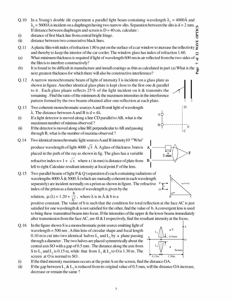
Pag
e
7
of
12
W
AV
E O
PT
ICS
Q.10 In a Young's double slit experiment a parallel light beam containing wavelength λ1 = 4000Å and
λ2 = 5600Å is incident on a diaphragm having two narrow slits. Separation between the slits is d = 2 mm.
If distance between diaphragm and screen is D = 40 cm, calculate :
(i) distance of first black line from central bright fringe.
(ii) distance between two consecutive black lines.
Q.11 A plastic film with index of refraction 1.80 is put on the surface of a car window to increase the reflectivity
and thereby to keep the interior of the car cooler. The window glass has index of refraction 1.60.
(a) What minimum thickness is required if light of wavelength 600 nm in air reflected from the two sides of
the film is to interfere constructively?
(b) It is found to be difficult in manufacture and install coatings as thin as calculated in part (a) What is the
next greatest thickness for which there will also be constructive interference?
Q.12 A narrow monochromatic beam of light of intensity I is incident on a glass plate as
shown in figure. Another identical glass plate is kept close to the first one & parallel
to it . Each glass plaate reflects 25 % of the light incident on it & transmits the
remaining . Find the ratio of the minimum & the maximum intensities in the interference
pattern formed by the two beams obtained after one reflection at each plate.
Q.13 Two coherent monochromatic sources A and B emit light of wavelength
λ. The distance between A and B is d = 4λ.
(i) If a light detector is moved along a line CD parallel to AB, what is the
maximum number of minima observed ?
(ii) If the detector is moved along a line BE perpendicular to AB and passing
through B, what is the number of maxima observed ?
Q.14 Two identical monochromatic light sources A and B intensity10–15W/m2
produce wavelength of light 4000 3 Å. A glass of thickness 3mm is
placed in the path of the ray as shown in fig. The glass has a variable
refractive index n = 1 + x where x ( in mm) is distance of plate from
left to right.Calculate resultant intensity at focal point F of the lens.
Q.15 Two parallel beams of light P & Q (separation d) each containing radiations of
wavelengths 4000 Å & 5000 Å (which are mutually coherent in each wavelength
separately) are incident normally on a prism as shown in figure. The refractive
index of the prism as a function of wavelength is given by the
relation, µ (λ) = 1.20 + 2
b
λ, where λ is in Å & b is a
positive constant. The value of b is such that the condition for total reflection at the face AC is just
satisfied for one wavelength & is not satisfied for the other, find the value of b. A convergent lens is used
to bring these transmitted beams into focus. If the intensities of the upper & the lower beams immediately
after transmission from the face AC, are 4I & I respectively, find the resultant intensity at the focus.
Q.16 In the figure shown S is a monochromatic point source emitting light of
wavelength = 500 nm . A thin lens of circular shape and focal length
0.10 m is cut into two identical halves L1 and L
2 by a plane passing
through a diameter . The two halves are placed symmetrically about the
central axis SO with a gap of 0.5 mm . The distance along the axis from
S to L1 and L
2 is 0.15 m, while that from L
1 & L
2 to O is 1.30 m . The
screen at O is normal to SO .
(i) If the third intensity maximum occurs at the point A on the screen, find the distance OA.
(ii) If the gap between L1 & L
2 is reduced from its original value of 0.5 mm, will the distance OA increase,
decrease or remain the same ?
7
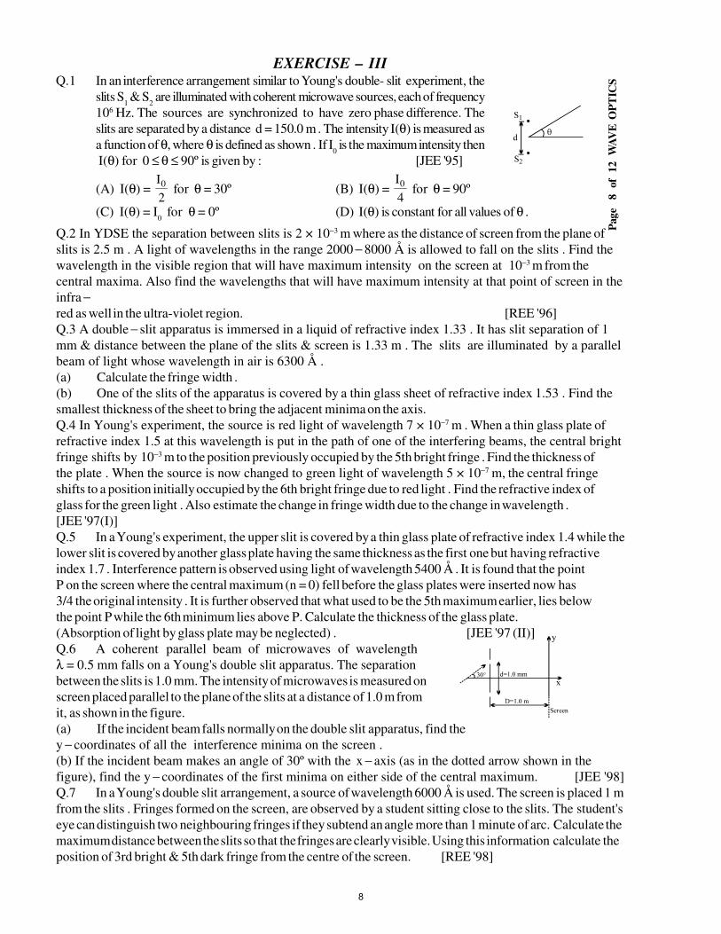
Pag
e
8
of
12
W
AV
E O
PT
ICS
EXERCISE – IIIQ.1 In an interference arrangement similar to Young's double- slit experiment, the
slits S1 & S
2 are illuminated with coherent microwave sources, each of frequency
106 Hz. The sources are synchronized to have zero phase difference. The
slits are separated by a distance d = 150.0 m . The intensity I(θ) is measured as
a function of θ, where θ is defined as shown . If I0 is the maximum intensity then
I(θ) for 0 ≤ θ ≤ 90º is given by : [JEE '95]
(A) I(θ) = 2
I0 for θ = 30º (B) I(θ) =
4
I0 for θ = 90º
(C) I(θ) = I0 for θ = 0º (D) I(θ) is constant for all values of θ .
Q.2 In YDSE the separation between slits is 2 × 10⁻³ m where as the distance of screen from the plane of
slits is 2.5 m . A light of wavelengths in the range 2000 − 8000 Å is allowed to fall on the slits . Find the wavelength in the visible region that will have maximum intensity on the screen at 10−3 m from the
central maxima. Also find the wavelengths that will have maximum intensity at that point of screen in the
infra −red as well in the ultra-violet region. [REE '96]
Q.3 A double − slit apparatus is immersed in a liquid of refractive index 1.33 . It has slit separation of 1
mm & distance between the plane of the slits & screen is 1.33 m . The slits are illuminated by a parallel beam of light whose wavelength in air is 6300 Å .
(a) Calculate the fringe width .
(b) One of the slits of the apparatus is covered by a thin glass sheet of refractive index 1.53 . Find the smallest thickness of the sheet to bring the adjacent minima on the axis.
Q.4 In Young's experiment, the source is red light of wavelength 7 × 10⁻⁷ m . When a thin glass plate of refractive index 1.5 at this wavelength is put in the path of one of the interfering beams, the central bright fringe shifts by 10−3 m to the position previously occupied by the 5th bright fringe . Find the thickness of
the plate . When the source is now changed to green light of wavelength 5 × 10⁻⁷ m, the central fringe
shifts to a position initially occupied by the 6th bright fringe due to red light . Find the refractive index of
glass for the green light . Also estimate the change in fringe width due to the change in wavelength .
[JEE '97(I)]
Q.5 In a Young's experiment, the upper slit is covered by a thin glass plate of refractive index 1.4 while the lower slit is covered by another glass plate having the same thickness as the first one but having refractive
index 1.7 . Interference pattern is observed using light of wavelength 5400 Å . It is found that the point
P on the screen where the central maximum (n = 0) fell before the glass plates were inserted now has
3/4 the original intensity . It is further observed that what used to be the 5th maximum earlier, lies below
the point P while the 6th minimum lies above P. Calculate the thickness of the glass plate.
(Absorption of light by glass plate may be neglected) . [JEE '97 (II)]
Q.6 A coherent parallel beam of microwaves of wavelength
λ = 0.5 mm falls on a Young's double slit apparatus. The separation
between the slits is 1.0 mm. The intensity of microwaves is measured on
screen placed parallel to the plane of the slits at a distance of 1.0 m from
it, as shown in the figure.
(a) If the incident beam falls normally on the double slit apparatus, find the
y − coordinates of all the interference minima on the screen .
(b) If the incident beam makes an angle of 30º with the x − axis (as in the dotted arrow shown in the
figure), find the y − coordinates of the first minima on either side of the central maximum. [JEE '98]
Q.7 In a Young's double slit arrangement, a source of wavelength 6000 Å is used. The screen is placed 1 m from the slits . Fringes formed on the screen, are observed by a student sitting close to the slits. The student's
eye can distinguish two neighbouring fringes if they subtend an angle more than 1 minute of arc. Calculate the
maximum distance between the slits so that the fringes are clearly visible. Using this information calculate the
position of 3rd bright & 5th dark fringe from the centre of the screen. [REE '98]
8
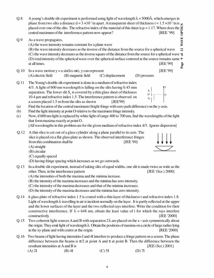
Pag
e
9
of
12
W
AV
E O
PT
ICS
Q.8 A young’s double slit experiment is performed using light of wavelength λ = 5000Å, which emerges in
phase from two slits a distance d = 3 ×10⁻⁷m apart. A transparent sheet of thickness t = 1.5 ×10⁻⁷m is
placed over one of the slits. The refractive index of the material of this sheet is µ = 1.17. Where does the
central maximum of the interference pattern now appear? [REE ’99]
Q.9 As a wave propagates,
(A) the wave intensity remains constant for a plane wave
(B) the wave intensity decreases as the inverse of the distance from the source for a spherical wave
(C) the wave intensity decreases as the inverse square of the distance from the source for a spherical wave
(D) total intensity of the spherical wave over the spherical surface centered at the source remains same
at all times. [JEE '99]
Q.10 In a wave motion y = a sin(kx-ωt), y can represent [JEE '99]
(A) electric field (B) magnetic field (C) displacement (D) pressure
Q.11 The Young's double slit experiment is done in a medium of refractive index
4/3. A light of 600 nm wavelength is falling on the slits having 0.45 mm
separation. The lower slit S2 is covered by a thin glass sheet of thickness
10.4 µm and refractive index 1.5. The interference pattern is observed on
a screen placed 1.5 m from the slits as shown [JEE'99]
(a) Find the location of the central maximum (bright fringe with zero path difference) on the y-axis.
(b) Find the light intensity at point O relative to the maximum fringe intensity.
(c) Now, if 600 nm light is replaced by white light of range 400 to 700 nm, find the wavelengths of the light
that form maxima exactly at point O .
[All wavelengths in this problem are for the given medium of refractive index 4/3. Ignore dispersion]
Q.12 A thin slice is cut out of a glass cylinder along a plane parallel to its axis. The
slice is placed on a flat glass plate as shown. The observed interference fringes
from this combination shall be [JEE '99]
(A) straight
(B) circular
(C) equally spaced
(D) having fringe spacing which increases as we go outwards.
Q.13 In a double slit experiment, instead of taking slits of equal widths, one slit is made twice as wide as the
other. Then, in the interference pattern [JEE '(Scr.) 2000]
(A) the intensities of both the maxima and the minima increase.
(B) the intensity of the maxima increases and the minima has zero intensity.
(C) the intensity of the maxima decreases and that of the minima increases.
(D) the intensity of the maxima decreases and the minima has zero intensity.
Q.14 A glass plate of refractive index 1.5 is coated with a thin layer of thickness t and refractive index 1.8.
Light of wavelength λ travelling in air is incident normally on the layer . It is partly reflected at the upper
and the lower surfaces of the layer and the two reflected rays interfere. Write the condition for their
constructive interference. If λ = 648 nm, obtain the least value of t for which the rays interfere
constructively. [JEE '2000]
Q.15 Two coherent light sources A and B with separation 2 λ are placed on the x − axis symmetrically about
the origin. They emit light of wavelength λ. Obtain the positions of maxima on a circle of large radius lying
in the xy-plane and with centre at the origin. [REE '2000]
Q.16 Two beams of light having intensities I and 4I interfere to produce a fringe pattern on a screen. The phase
difference between the beams is π/2 at point A and π at point B. Then the difference between the
resultant intensities at A and B is [JEE (Scr.) 2001]
(A) 2I (B) 4I (C) 5I (D) 7I
9
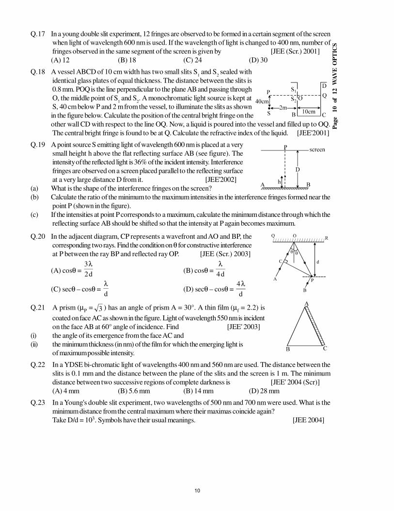
Page
10
of
12
W
AV
E O
PT
ICS
Q.17 In a young double slit experiment, 12 fringes are observed to be formed in a certain segment of the screen
when light of wavelength 600 nm is used. If the wavelength of light is changed to 400 nm, number of
fringes observed in the same segment of the screen is given by [JEE (Scr.) 2001]
(A) 12 (B) 18 (C) 24 (D) 30
Q.18 A vessel ABCD of 10 cm width has two small slits S1 and S
2 sealed with
identical glass plates of equal thickness. The distance between the slits is
0.8 mm. POQ is the line perpendicular to the plane AB and passing through
O, the middle point of S1 and S
2. A monochromatic light source is kept at
S, 40 cm below P and 2 m from the vessel, to illuminate the slits as shown
in the figure below. Calculate the position of the central bright fringe on the
other wall CD with respect to the line OQ. Now, a liquid is poured into the vessel and filled up to OQ.
The central bright fringe is found to be at Q. Calculate the refractive index of the liquid. [JEE'2001]
Q.19 A point source S emitting light of wavelength 600 nm is placed at a very
small height h above the flat reflecting surface AB (see figure). The
intensity of the reflected light is 36% of the incident intensity. Interference
fringes are observed on a screen placed parallel to the reflecting surface
at a very large distance D from it. [JEE'2002]
(a) What is the shape of the interference fringes on the screen?
(b) Calculate the ratio of the minimum to the maximum intensities in the interference fringes formed near the
point P (shown in the figure).
(c) If the intensities at point P corresponds to a maximum, calculate the minimum distance through which the
reflecting surface AB should be shifted so that the intensity at P again becomes maximum.
Q.20 In the adjacent diagram, CP represents a wavefront and AO and BP, the
corresponding two rays. Find the condition on θ for constructive interference
at P between the ray BP and reflected ray OP. [JEE (Scr.) 2003]
(A) cosθ = d2
3λ(B) cosθ =
d4
λ
(C) secθ – cosθ = d
λ(D) secθ – cosθ =
d
4λ
Q.21 A prism (µP = 3 ) has an angle of prism A = 30°. A thin film (µ
f = 2.2) is
coated on face AC as shown in the figure. Light of wavelength 550 nm is incident
on the face AB at 60° angle of incidence. Find [JEE' 2003]
(i) the angle of its emergence from the face AC and
(ii) the minimum thickness (in nm) of the film for which the emerging light is
of maximum possible intensity.
Q.22 In a YDSE bi-chromatic light of wavelengths 400 nm and 560 nm are used. The distance between the
slits is 0.1 mm and the distance between the plane of the slits and the screen is 1 m. The minimum
distance between two successive regions of complete darkness is [JEE' 2004 (Scr)]
(A) 4 mm (B) 5.6 mm (B) 14 mm (D) 28 mm
Q.23 In a Young's double slit experiment, two wavelengths of 500 nm and 700 nm were used. What is the
minimum distance from the central maximum where their maximas coincide again?
Take D/d = 103. Symbols have their usual meanings. [JEE 2004]
10
Page
11
of
12
W
AV
E O
PT
ICS
Q.24 In Young's double slit experiment maximum intensity is I than the angular position where the intensity
becomes 4
Iis: [JEE' 2005 (Scr)]
(A) sin–1
λ
d(B) sin–1
λ
d3(C) sin–1
λ
d2(D) sin–1
λ
d4
Q.25 In Young’s double slit experiment an electron beam is used to form a fringe pattern instead of light. If
speed of the electrons is increased then the fringe width will : [JEE' 2005 (Scr)]
(A) increase (B) decrease
(C) remains same (D) no fringe pattern will be formed
ANSWER KEYEXERCISE – I
Q.1 0.225 mm Q.2 18 Q.3 2λ Q.4 8 µm
Q.5 1/3 Q.6 81 : 1 Q.7λ−µ t)1(2
Q.8 1.98 × 10⁻² mm
Q.9 5000Å Q.10 0.2 mm Q.11 35.35 cm
Q.12 4.8 µm Q.13 (25/24)×10−7 m Q.14 0.15 mm Q.15 141
Q.16 ±
+−
8
1n2cos 1
, n = 0, 1, 2, 3 & π ±
+−
8
1n2cos 1
n = 0, 1, 2, 3
Q.17 λ = 5850 Å Q.18 6000 Å Q.19 0 , 1.5 mm
11
Page
12
of
12
W
AV
E O
PT
ICS
EXERCISE – II
Q.1 vy
x
λ Q.2 (a) I0 =
λ
−µπ t)1(secI
2 , (b) 4 µm
Q.3 (i) λ
π
µ+=φ∆
2d
D
1
l (ii) ;
d
D
1 2
λπ
+µ
=φ∆l
;d2
D
2Dmin
λ=
β=
Q.4 X - coordinate = 'DcoordinateY;d
'Dn−=−
λ, Where D’ = D + Mg/K (1– cosωt)
Q.5 (a) tB = 120 µm (b) β = 6mm; I
max = 9I, I
min = I (c) β/6 = 1mm (d) I (at 5cm above 0) = 9I,
I (at 5 cm below 0) = 3I
Q.6 λ = 600 nm, t = 24 µm
Q.7 (i) I/3, (ii) I/9, (iii) 0.6 mm, (iv) 0.2mm downwards , (v) 8mm down, (vi) I
Q.8 5 Q.9 3/4 Q.10 (i) 280 µm, (ii) 560 µm
Q.11 (a) 8.33 × 10⁻⁸ m, (b) 2.5 × 10⁻⁷ m Q.12 1 : 49 Q.13 (i) 8, (ii) 4
Q.14 4 × 10–15 W/m2 Q.15 8.0 × 10⁵ Å2 , 9 I Q.16 (i) 1 mm (ii) increase
EXERCISE – III
Q.1 A, C Q.2 4000 Å, 8000 Å , 3
8000 Å , 2000 Å Q.3 0.63 mm, 1.575 µm
Q.4 7 µm , 1.6 , 7
400 µm (decrease) Q.5 9.3 µm
Q.6 (a) ± 15
1 , ±
7
3 (b) +
15
1 ,
7
3Q.7
π48.6
;6.3
π mm ,
4.2
π mm
Q.8 y = 0.085 D ; D = distance between screen & slits Q.9 A, C, D
Q.10 A, B, C Q.11 (a) y = − 13/3 mm, (b) intensity at O = 0.75Imax
(c) 650 nm, 433.33 nm
Q.12 A Q.13 A Q.14 t = 2.7
λ,
2.7
3λ, ...... ; t
minimum =
2.7
λ= 90 nm
Q.15 (0, – R),
−
2
3R,
2
R, (R, 0),
2
3R,
2
R, (0, R)
−
2
3R,
2
R, ( – R, 0)
−−
2
3R,
2
R
Q.16 B Q.17 B Q.18 (i) y = 2 cm, (ii) µ = 1.0016
Q.19 (a) circular, (b) 16, (c) 3000Å Q.20 B Q.21 0, 125 nm
Q.22 D Q.23 3.5 mm Q.24 B Q.25 B
12
STUDY PACKAGE
Target: IIT-JEE (Advanced)
SUBJECT: PHYSICS
TOPIC: XII P10 Modern Physics
Index:
1. Key Concepts
2. Exercise I
3. Exercise II
4. Exercise III
5. Exercise IV
6. Answer Key
7. 34 Yrs. Que. from IIT-JEE
8. 10 Yrs. Que. from AIEEE
1
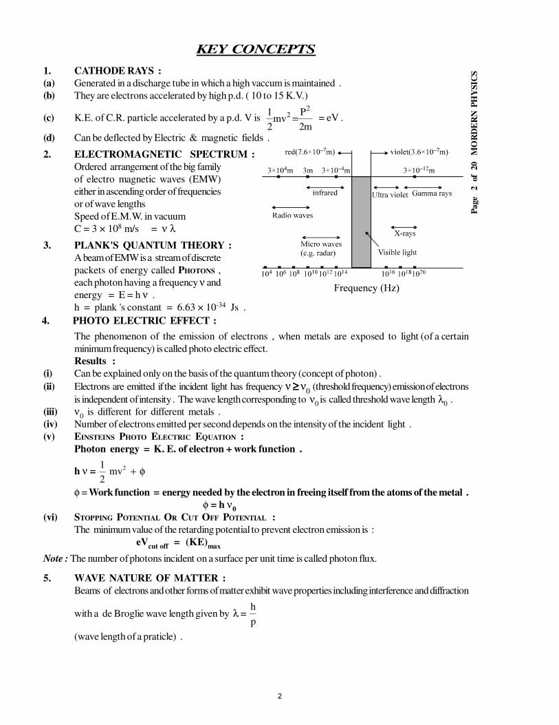
Page
2
of 2
0
MO
RD
ER
N P
HY
SIC
S
KEY CONCEPTS
1. CATHODE RAYS :
(a) Generated in a discharge tube in which a high vaccum is maintained .
(b) They are electrons accelerated by high p.d. ( 10 to 15 K.V.)
(c) K.E. of C.R. particle accelerated by a p.d. V is m2
Pmv
2
1 22 = = eV .
(d) Can be deflected by Electric & magnetic fields .
2. ELECTROMAGNETIC SPECTRUM :
Ordered arrangement of the big family
of electro magnetic waves (EMW)
either in ascending order of frequencies
or of wave lengths
Speed of E.M.W. in vacuum
C = 3 × 10⁸ m/s = ν λ
3. PLANK'S QUANTUM THEORY :
A beam of EMW is a stream of discrete
packets of energy called PHOTONS ,
each photon having a frequency ν and
energy = E = h ν .
h = plank 's constant = 6.63 × 10⁻³⁴ Js .
4. PHOTO ELECTRIC EFFECT :
The phenomenon of the emission of electrons , when metals are exposed to light (of a certain
minimum frequency) is called photo electric effect.
Results :
(i) Can be explained only on the basis of the quantum theory (concept of photon) .
(ii) Electrons are emitted if the incident light has frequency ν ≥≥≥≥ ν0 (threshold frequency) emission of electrons
is independent of intensity . The wave length corresponding to ν0 is called threshold wave length λ
0 .
(iii) ν0 is different for different metals .
(iv) Number of electrons emitted per second depends on the intensity of the incident light .
(v) EINSTEINS PHOTO ELECTRIC EQUATION :
Photon energy = K. E. of electron + work function .
h ν =1
2
2mv + φ
φ = Work function = energy needed by the electron in freeing itself from the atoms of the metal .
φ = h ν0
(vi) STOPPING POTENTIAL OR CUT OFF POTENTIAL :
The minimum value of the retarding potential to prevent electron emission is :
eVcut off
= (KE)max
Note : The number of photons incident on a surface per unit time is called photon flux.
5. WAVE NATURE OF MATTER :
Beams of electrons and other forms of matter exhibit wave properties including interference and diffraction
with a de Broglie wave length given by λ = h
p
(wave length of a praticle) .
2
Page
3
of 2
0
MO
RD
ER
N P
HY
SIC
S
6. ATOMIC MODELS :
(a) THOMSON MODEL : (PLUM PUDDING MODEL)
(i) Most of the mass and all the positive charge of an atom is uniformly distributed over the full size
of atom (10-10 m) .
(ii) Electrons are studded in this uniform distribution .
(iii) Failed to explain the large angle scattering α - particle scattered by thin foils of matter .
(b) RUTHERFORD MODEL : ( Nuclear Model)
(i) The most of the mass and all the positive charge is concentrated within a size of 10-14 m inside
the atom . This concentration is called the atomic nucleus .
(ii) The electron revolves around the nucleus under electric interaction between them in circular orbits.
An accelerating charge radiates the nucleus spiralling inward and finally fall into the nucleus ,
which does not happen in an atom. This could not be explained by this model .
(c) BOHR ATOMIC MODEL :
Bohr adopted Rutherford model of the atom & added some arbitrary conditions. These conditions are
known as his postulates :
(i) The electron in a stable orbit does not radiate energy . i.e. mv
r
k ze
r
2 2
2=
(ii) A stable orbit is that in which the angular momentum of the electron about nucleus
is an integral (n) multiple of h
2π. i.e. mvr = n
h
2π; n = 1 , 2 , 3 , .......(n ≠ 0).
(iii) The electron can absorb or radiate energy only if the electron jumps from a lower
to a higher orbit or falls from a higher to a lower orbit .
(iv) The energy emitted or absorbed is a light photon of frequency ν and of energy . E = hνννν .
FOR HYDROGEN ATOM : (Z = atomic number = 1)
(i) Ln = angular momentum in the nth orbit = n
h
2π .
(ii) rn = radius of nth circular orbit = (0.529 Aº) n2 ; (1Aº = 10-10 m) ; r
n α n2.
(iii) En Energy of the electron in the nth orbit =
− 13 62
. ev
ni.e. E
n α
12
n .
Note : Total energy of the electron in an atom is negative , indicating that it is bound .
Binding Energy (BE)n = - E
n =
13 62
. ev
n.
(iv) En2
- En1
= Energy emitted when an electron jumps from n2
th orbit to n1
th orbit (n2 > n
1) .
∆E = (13.6 ev)
−
2
2
2
1n
1
n
1 .
∆E = hν ; ν = frequency of spectral line emitted .
1
λ = ν = wave no. [ no. of waves in unit length (1m)] = R
−
2
2
2
1n
1
n
1 .
Where R = Rydberg's constant for hydrogen = 1.097 × 10⁷ m-1 .
(v) For hydrogen like atom/spicies of atomic number Z :
rnz
= Bohr radius
Z n2 = (0.529 Aº)
n
Z
2
; Enz
= (– 13.6) Z
n
2
2 ev
Rz = RZ2 – Rydberg's constant for element of atomic no. Z .
Note : If motion of the nucleus is also considered , then m is replaced by µ .
3
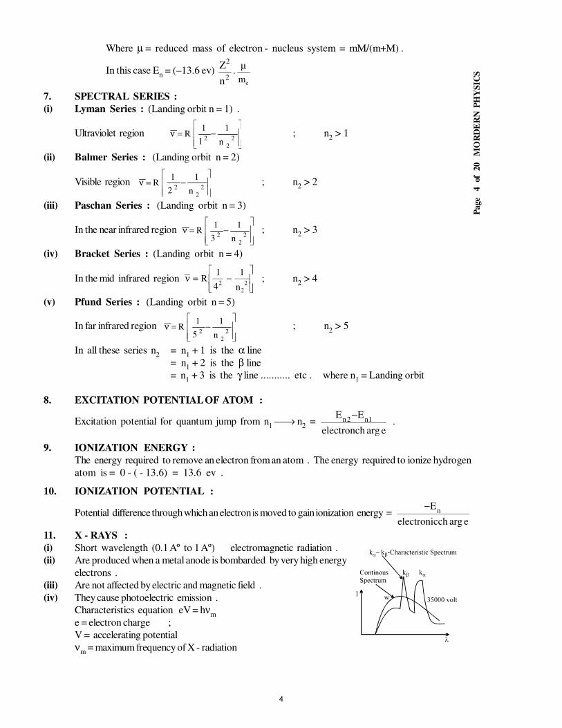
Page
4
of 2
0
MO
RD
ER
N P
HY
SIC
S
Where µ = reduced mass of electron - nucleus system = mM/(m+M) .
In this case En = (–13.6 ev)
2
2
n
Z.
µ
me
7. SPECTRAL SERIES :
(i) Lyman Series : (Landing orbit n = 1) .
Ultraviolet region
−=ν
2
2
2n
1
1
1R ; n
2 > 1
(ii) Balmer Series : (Landing orbit n = 2)
Visible region
−=ν
2
2
2n
1
2
1R ; n
2 > 2
(iii) Paschan Series : (Landing orbit n = 3)
In the near infrared region
−=ν
2
2
2n
1
3
1R ; n
2 > 3
(iv) Bracket Series : (Landing orbit n = 4)
In the mid infrared region ν = −
Rn
1
4
12
2
2; n
2 > 4
(v) Pfund Series : (Landing orbit n = 5)
In far infrared region
−=ν
2
2
2n
1
5
1R ; n
2 > 5
In all these series n2
= n1 + 1 is the α line
= n1 + 2 is the β line
= n1 + 3 is the γ line ........... etc . where n
1 = Landing orbit
8. EXCITATION POTENTIAL OF ATOM :
Excitation potential for quantum jump from n1 → n
2 =
eargchelectron
EE1n2n
− .
9. IONIZATION ENERGY :
The energy required to remove an electron from an atom . The energy required to ionize hydrogen
atom is = 0 - ( - 13.6) = 13.6 ev .
10. IONIZATION POTENTIAL :
Potential difference through which an electron is moved to gain ionization energy = eargchelectronic
En
−
11. X - RAYS :
(i) Short wavelength (0.1 Aº to 1 Aº) electromagnetic radiation .
(ii) Are produced when a metal anode is bombarded by very high energy
electrons .
(iii) Are not affected by electric and magnetic field .
(iv) They cause photoelectric emission .
Characteristics equation eV = hνm
e = electron charge ;
V = accelerating potential
νm
= maximum frequency of X - radiation
4
Page
5
of 2
0
MO
RD
ER
N P
HY
SIC
S
(v) Intensity of X - rays depends on number of electrons hitting the target .
(vi) Cut off wavelength or minimum wavelength, where v (in volts) is the p.d. applied to the tube
V
12400min
≅λ Aº .
(vii) Continuous spectrum due to retardation of electrons .
(viii) Characteristic Spectrum due to transition of electron from higher to lower
ν α (z - b)2 ; υ = a (z - b)2 [ MOSELEY'S LAW ]
b = 1 for K series ; b = 7.4 for L series
Where b is Shielding factor (different for different series) .
Note : (i) Binding energy = - [ Total Mechanical Energy ]
(ii) Vel. of electron in nth orbit for hydrogen atom ≅ c
n137 ; c = speed of light .
(iii) For x - rays ( )
−−=
λ 2
2
2
1
2
n
1
n
1bzR
1
(iv) Series limit of series means minimum wave length of that series.
12. NUCLEAR DIMENSIONS :
R = Ro A1/3 Where R
o = empirical constant = 1.1 × 10⁻¹⁵ m ; A = Mass number of the atom
13. RADIOACTIVITY :
The phenomenon of self emission of radiation is called radioactivity and the substances which emit these
radiations are called radioactive substances . It can be natural or artificial (induced) .
14. α , β , γ RADIATION :
(i) α − particle :
(a) Helium nucleus (2He4) ; (b) energy varies from 4 Mev to 9 Mev ;
(c) Velocity 106 − 107 m/s ; (d) low penetration
(ii) β − particle :
(a) Have much less energy ; (b) more penetration ; (c) higher velocities than α particles
(iii) γ − radiation : Electromagnetic waves of very high energy .
15. LAWS OF RADIOACTIVE DISINTEGRATION :
(A) DISPLACEMENT LAW : In all radioactive transformation either an α or β particle (never both or more
than one of each simultaneously) is emitted by the nucleus of the atom.
(i) α − emission :zXA →
z − 2YA − 4 +
2α4 + Energy
(ii) β − emission :zXA →
β +
z + 1YA + ν (antinuetrino)
(iii) γ − emission : emission does not affect either the charge number or
the mass number .
(B) STASTISTICAL LAW : The disintegration is a random phenomenon . Whcih atom disintegrates first is
purely a matter of chance .
Number of nuclei disintegrating per second is given ;
(disintegration /s /gm is called specific activity) .
(i) Ntd
NdN
td
Ndλ−=→α = activity .
Where N = No. of nuclei present at time t ; λ = decay constant
(ii) N = No
e− λt No = number of nuclei present in the beginning .
5
Page
6
of 2
0
MO
RD
ER
N P
HY
SIC
S
(iii) Half life of the population T1/2
= 0 693.
λ;
at the end of n half−life periods the number of nuclei left N = No
n2 .
(iv) MEAN LIFE OF AN ATOM = atomsofnumbertotal
atomsalloftimelifeΣ ; TT
av =
1
λ
(v) CURIE : The unit of activity of any radioactive substance in which the number of disintegration
per second is 3.7 ×10¹⁰ .
16. ATOMIC MASS UNIT ( a.m.u. OR U) :
1 amu = 1
12 × (mass of carbon − 12 atom) = 1.6603 × 10⁻²⁷ kg
17. MASS AND ENERGY :
The mass m of a particle is equivalent to an energy given by E = mc2 ;
c = speed of light . 1 amu = 931 Mev
18. MASS DEFECT AND BINDING ENERGY OF A NUCLEUS :
The nucleus is less massive than its constituents . The difference of masses is called mass defect .
∆ M = mass defect = [ Zmp
+ (A − Z) mn] − M
zA .
Total energy required to be given to the nucleus to tear apart the individual nucleons co mposing
the nucleus , away from each other and beyond the range of interaction forces is called the Binding
Energy of a nucleus .
B.E. = (∆ M)C2 .
B.E. per nucleon = ( )∆ M C
A
2
.
Greater the B.E. , greater is the stability of the nucleus .
19. NUCLEAR FISSION :
(i) Heavy nuclei of A , above 200 , break up onto two or more fragments of comparable masses.
(ii) The total B.E. increases and excess energy is released .
(iii) The man point of the fission energy is leberated in the form of the K.E. of the fission fragments
. eg. 1o
9236
14156
23692
1o
23592
n3KrBaUnU ++→→+ + energy
20. NUCLEAR FUSION ( Thermo nuclear reaction) :
(i) Light nuclei of A below 20 , fuse together , the B.E. per nucleon increases and hence the excess energy
is released .
(ii) These reactions take place at ultra high temperature ( ≅ 107 to 109)
(iii) Energy released exceeds the energy liberated in the fission of heavy nuclei .
eg . eHeP4 01
41
11 ++→ . (Positron)
(iv) The energy released in fusion is specified by specifying Q value .
i.e. Q value of reaction = energy released in a reaction .
Note : (i) In emission of β− , z increases by 1 .
(ii) In emission of β+ , z decreases by 1 .
6
Page
7
of 2
0
MO
RD
ER
N P
HY
SIC
S
EXERCISE # I
Q.1 A parallel beam of uniform, monochromatic light of wavelength 2640 A has an intensity of
200W/m2. The number of photons in 1mm3 of this radiation are ........................
Q.2 When photons of energy 4.25eV strike the surface of a metal A, the ejected photoelectrons have maximum
kinetic energy Ta eV and de Broglie wavelength λ
a. The maximum kinetic energy of photoelectrons
liberated from another metal B by photons of energy 4.7eV is Tb = (T
a – 1.5) eV. If the De Broglie
wavelength of these photoelectrons is λb = 2λ
a, then find
(a) The work function of a (b) The work function of b is (c) Ta and T
b
Q.3 When a monochromatic point source of light is at a distance of 0.2 m from a photoelectric cell, the cut off
voltage and the saturation current are respectively 0.6 volt and 18.0 mA. If the same source is placed
0.6 m away from the photoelectric cell, then find
(a) the stopping potential (b) the saturation current
Q.4 An isolated metal body is illuminated with monochromatic light and is observed to become charged to
a steady positive potential 1.0 V with respect to the surrounding. The work function of the metal is
3.0 eV. The frequency of the incident light is ______________.
Q.5 663 mW of light from a 540 nm source is incident on the surface of a metal. If only 1 of each 5 × 10⁹
incident photons is absorbed and causes an electron to be ejected from the surface, the total photocurrent
in the circuit is ________.
Q.6 Light of wavelength 330 nm falling on a piece of metal ejects electrons with sufficient energy which
requires voltage V0 to prevent a collector. In the same setup, light of wavelength 220 nm, ejects electrons
which require twice the voltage V0 to stop them in reaching a collector. Find the numerical value of
voltage V0.(Take plank's constant, h = 6.6 × 10⁻³⁴ Js and 1 eV = 1.6 × 10⁻¹⁹ J)
Q.7 A hydrogen atom in a state having a binding energy 0.85eV makes a transition to a state of excitation
energy 10.2eV. The wave length of emitted photon is ....................nm.
Q.8 A hydrogen atom is in 5th excited state. When the electron jumps to ground state the velocity of recoiling
hydrogen atom is ................ m/s and the energy of the photon is ............eV.
Q.9 The ratio of series limit wavlength of Balmer series to wavelength of first line of paschen series is .............
Q.10 An electron joins a helium nucleus to form a He+ ion. The wavelength of the photon emitted in this process
if the electron is assumed to have had no kinetic energy when it combines with nucleus is .........nm.
Q.11 Three energy levels of an atom are shown in the figure. The wavelength
corresponding to three possible transition are λ1, λ
2 and λ
3. The value
of λ3 in terms of λ
1 and λ
2 is given by ______.
Q.12 Imagine an atom made up of a proton and a hypothetical particle of double the mass of an electron but
having the same charge as the electron. Apply the Bohr atom model and consider a possible transitions
of this hypothetical particle to the first excited level. Find the longest wavelngth photon that will be
emitted λ (in terms of the Rydberg constant R.)
Q.13 In a hydrogen atom, the electron moves in an orbit of radius 0.5 Å making 1016 revolution per second.
The magnetic moment associated with the orbital motion of the electron is _______.
Q.14 The positron is a fundamental particle with the same mass as that of the electron and with a charge equal
to that of an electron but of opposite sign. When a positron and an electron collide, they may annihilate
each other. The energy corresponding to their mass appears in two photons of equal energy. Find the
wavelength of the radiation emitted.
[Take : mass of electron = (0.5/C2)MeV and hC = 1.2×10⁻¹² MeV.m where h is the Plank's constant
and C is the velocity of light in air]
7
Page
8
of 2
0
MO
RD
ER
N P
HY
SIC
S
Q.15 A small 10W source of ultraviolet light of wavelength 99 nm is held at a distance 0.1 m from a metal
surface. The radius of an atom of the metal is approximately 0.05 nm. Find
(i) the average number of photons striking an atom per second.
(ii) the number of photoelectrons emitted per unit area per second if the efficiency of liberation of photoelectrons is 1%.
Q.16 The surface of cesium is illuminated with monochromatic light of various
wavelengths and the stopping potentials for the wavelengths are measured. The
results of this experiment is plotted as shown in the figure. Estimate the value of
work function of the cesium and Planck’s constant.
Q.17 A hydrogen like atom has its single electron orbiting around its stationary nucleus. The energy to excite
the electron from the second Bohr orbit to the third Bohr orbit is 47.2 eV. The atomic number of this
nucleus is ______________.
Q.18 A single electron orbits a stationary nucleus of charge Ze where Z is a constant and e is the electronic
charge. It requires 47.2eV to excite the electron from the 2nd Bohr orbit to 3rd Bohr orbit. Find
(i) the value of Z,
(ii) energy required to excite the electron from the third to the fourth orbit
(iii) the wavelength of radiation required to remove the electron from the first orbit to infinity
(iv) the kinetic energy, potential energy and angular momentum in the first Bohr orbit
(v) the radius of the first Bohr orbit.
Q.19 A hydrogen like atom (atomic number Z) is in higher excited state of quantum number n. This excited
atom can make a transition to the first excited state by successively emitting two photons of energy
22.95eV and 5.15eV respectively. Alternatively, the atom from the same excited state can make transition
to the second excited state by successively emitting two photons of energies 2.4eV and 8.7eV respectively.
Find the values of n and Z.
Q.20 Find the binding energy of an electron in the ground state of a hydrogen like atom in whose spectrum the
third of the corresponding Balmer series is equal to 108.5nm.
Q.21 Which level of the doubly ionized lithium has the same energy as the ground state energy of the hydrogen
atom. Find the ratio of the two radii of corresponding orbits.
Q.22 The binding energies per nucleon for deuteron (1H2) and helium (
2He4) are 1.1 MeV and 7.0 MeV
respectively. The energy released when two deuterons fuse to form a helium nucleus (2He4) is ________.
Q.23 A radioactive decay counter is switched on at t = 0. A β - active sample is present near the counter. The
counter registers the number of β - particles emitted by the sample. The counter registers 1 × 10⁵
β - particles at t = 36 s and 1.11 × 10⁵ β - particles at t = 108 s. Find T½ of this sample
Q.24 An isotopes of Potassium K4019
has a half life of 1.4 × 10⁹ year and decays to Argon Ar4018 which is stable.
(i) Write down the nuclear reaction representing this decay.
(ii) A sample of rock taken from the moon contains both potassium and argon in the ratio 1/7. Find age of
rock
Q.25 At t = 0, a sample is placed in a reactor. An unstable nuclide is produced at a constant rate R in the
sample by neutron absorption. This nuclide β— decays with half life τ. Find the time required to produce
80% of the equilibrium quantity of this unstable nuclide.
Q.26 Suppose that the Sun consists entirely of hydrogen atom and releases the energy by the nuclear reaction,
H4 11
→ He42
with 26 MeV of energy released. If the total output power of the Sun is assumed to
remain constant at 3.9 × 1026 W, find the time it will take to burn all the hydrogen. Take the mass of the
Sun as 1.7 × 1030 kg.
8
Page
9
of 2
0
MO
RD
ER
N P
HY
SIC
S
Q.27 Assuming that the source of the energy of solar radiation is the energy of the formation of helium from
hydrogen according to the following cyclic reaction :
6C12 +
1H1 →
7N13 →
6C13 +
+1e0
6C13 +
1H1 →
7N14
7N14 +
1H1 →
8O15 →
7N15 +
+1e0
7N15 +
1H1 →
6C12 +
2He4
Find how many tons of hydrogen must be converted every second into helium . The solar constant is
8 J / cm2 min. Assume that hydrogen forms 35% of the sun's mass . Calculate in how many years this
hydrogen will be used up if the radiation of the sun is constant . me = 5.49 × 10⁻⁴ amu, atomic masses
mH=1.00814 amu, m
He=4.00388 amu, mass of the sun=2 × 1030 kg, distance between the sun and the
earth= 1.5× 10¹¹m. 1 amu = 931 MeV.
Q.28 An electron of mass "m" and charge "e" initially at rest gets accelerated by a constant electric field E. The
rate of change of DeBroglie wavelength of this electron at time t is .................
List of recommended questions from I.E. Irodov.
5.247, 5.249, 5.260, 5.262, 5.263, 5.264, 5.265, 5.266, 5.270, 5.273, 5.277
6.21, 6.22, 6.27, 6.28, 6.30, 6.31, 6.32, 6.33, 6.35, 6.37, 6.38, 6.39, 6.40,
6.41, 6.42, 6.43, 6.49, 6.50, 6.51, 6.52, 6.53, 6.133, 6.134, 6.135, 6.136,
6.137, 6.138, 6.141, 6.214, 6.233, 6.249, 6.264, 6.289
EXERCISE # II
Q.1 Find the force exerted by a light beam of intensity I, incident on a cylinder
(height h and base radius R) placed on a smooth surface as shown in figure if:
(a) surface of cylinder is perfectly reflecting
(b) surface of cylinder is having reflection coefficient 0.8. (assume no
transmission)
Q.2 A small plate of a metal (work function = 1.17 eV) is placed at a distance of 2m from a monochromatic
light source of wave length 4.8 × 10⁻⁷ m and power 1.0 watt. The light falls normally on the plate. Find
the number of photons striking the metal plate per square meter per sec. If a constant uniform
magnetic field of strength 10–4 tesla is applied parallel to the metal surface. Find the radius of the
largest circular path followed by the emitted photoelectrons.
Q.3 Electrons in hydrogen like atoms (Z = 3) make transitions from the fifth to the fourth orbit & from the
fourth to the third orbit. The resulting radiations are incident normally on a metal plate & eject photo
electrons. The stopping potential for the photoelectrons ejected by the shorter wavelength is
3.95 volts. Calculate the work function of the metal, & the stopping potential for the photoelectrons
ejected by the longer wavelength. (Rydberg constant = 1.094 × 10⁷ m–1)
Q.4 A beam of light has three wavelengths 4144Å, 4972Å & 6216 Å with a total intensity of
3.6×10⁻³ W.m–2 equally distributed amongst the three wavelengths. The beam falls normally on an area
1.0 cm2 of a clean metallic surface of work function 2.3 eV. Assume that there is no loss of light by
reflection and that each energetically capable photon ejects one electron. Calculate the number of
photoelectrons liberated in two seconds.
9
Pa
ge
10
of 2
0
MO
RD
ER
N P
HY
SIC
S
Q.5 Monochromatic radiation of wavelength λ1 = 3000Å falls on a photocell operating in saturating mode.
The corresponding spectral sensitivity of photocell is J = 4.8 × 10⁻³ A/w. When another monochromatic
radiation of wavelength λ2 = 1650Å and power P = 5 × 10⁻³ W is incident, it is found that maximum
velocity of photoelectrons increases n = 2 times. Assuming efficiency of photoelectron generation per
incident photon to be same for both the cases, calculate
(i) threshold wavelength for the cell. (ii) saturation current in second case.
Q.6 A monochromatic point source S radiating wavelength 6000 Å with
power 2 watt, an aperture A of diameter 0.1 m & a large screen SC are
placed as shown in figure . A photoemissive detector D of surface area
0.5 cm2 is placed at the centre of the screen. The efficiency of the detector
for the photoelectron generation per incident photon is 0.9.
(i) Calculate the photon flux density at the centre of the screen and the
photocurrent in the detector .
(ii) If a concave lens L of focal length 0.6 m is inserted in the aperture as shown, find the new values of
photon flux density & photocurrent Assume a uniform average transmission of 80% for the lens .
(iii) If the work-function of the photoemissive surface is 1 eV, calculate the values of the stopping potential in
the two cases (without & with the lens in the aperture).
Q.7 A small 10 W source of ultraviolet light of wavelength 99 nm is held at a distance 0.1 m from a metal
surface. The radius of an atom of the metal is approximaterly 0.05 nm. Find :
(i) the number of photons striking an atom per second.
(ii) the number of photoelectrons emitted per second if the efficiency of liberation of photoelectrons is 1%.
Q.8 A neutron with kinetic energy 25 eV strikes a stationary deuteron. Find the de Broglie wavelengths of
both particles in the frame of their centre of mass.
Q.9 Two identical nonrelativistic particles move at right angles to each other, possessing De Broglie wavelengths,
λ1 & λ
2 . Find the De Broglie wavelength of each particle in the frame of their centre of mass.
Q.10 A stationary He+ ion emitted a photon corresponding to the first line its Lyman series. That photon liberated a
photoelectron from a stationary hydrogen atom in the ground state. Find the velocity of the photoelectron.
Q.11 A gas of identical hydrogen like atoms has some atoms in the lowest (ground) energy level A & some
atoms in a particular upper (excited) energy level B & there are no atoms in any other energy level. The
atoms of the gas make transition to a higher energy level by the absorbing monochromatic light of
photon energy 2.7eV. Subsequently, the atoms emit radiation of only six different photon energies. Some
of the emitted photons have energy 2.7 eV. Some have energy more and some have less than 2.7 eV.
(i) Find the principal quantum number of the initially excited level B.
(ii) Find the ionisation energy for the gas atoms.
(iii) Find the maximum and the minimum energies of the emitted photons.
Q.12 A hydrogen atom in ground state absorbs a photon of ultraviolet radiation of wavelength 50 nm. Assuming that
the entire photon energy is taken up by the electron, with what kinetic energy will the electron be ejected ?
Q.13 A monochromatic light source of frequency ν illuminates a metallic surface and ejects photoelectrons.
The photoelectrons having maximum energy are just able to ionize the hydrogen atoms in ground state.
When the whole experiment is repeated with an incident radiation of frequency (5/6)ν , the photoelectrons
so emitted are able to excite the hydrogen atom beam which then emits a radiation of wavelength of
1215 Å . Find the work function of the metal and the frequency ν.
10
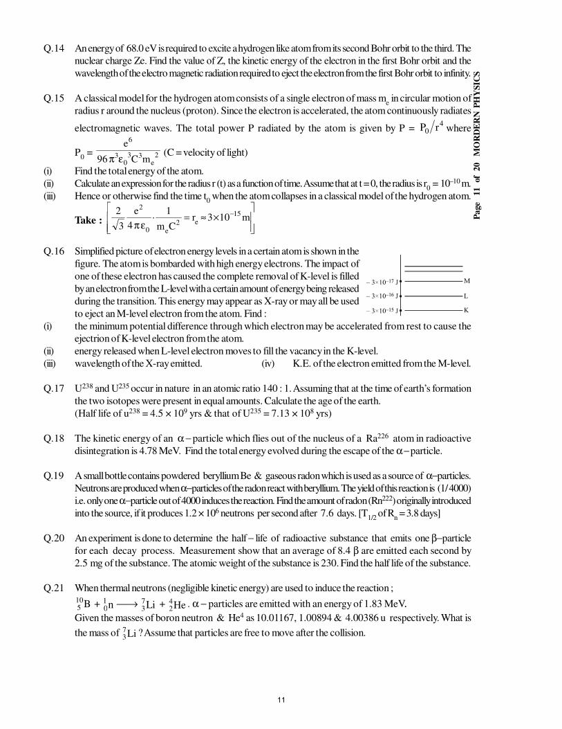
Pa
ge
11
of 2
0
MO
RD
ER
N P
HY
SIC
S
Q.14 An energy of 68.0 eV is required to excite a hydrogen like atom from its second Bohr orbit to the third. The
nuclear charge Ze. Find the value of Z, the kinetic energy of the electron in the first Bohr orbit and the
wavelength of the electro magnetic radiation required to eject the electron from the first Bohr orbit to infinity.
Q.15 A classical model for the hydrogen atom consists of a single electron of mass me in circular motion of
radius r around the nucleus (proton). Since the electron is accelerated, the atom continuously radiates
electromagnetic waves. The total power P radiated by the atom is given by P = 4
0 rP where
P0 = 2
e33
03
6
mC96
e
επ (C = velocity of light)
(i) Find the total energy of the atom.
(ii) Calculate an expression for the radius r (t) as a function of time. Assume that at t = 0, the radius is r0 = 10–10 m.
(iii) Hence or otherwise find the time t0 when the atom collapses in a classical model of the hydrogen atom.
Take :
×≈=
επ− m103r
Cm
1·
4
e
3
2 15
e2e0
2
Q.16 Simplified picture of electron energy levels in a certain atom is shown in the
figure. The atom is bombarded with high energy electrons. The impact of
one of these electron has caused the complete removal of K-level is filled
by an electron from the L-level with a certain amount of energy being released
during the transition. This energy may appear as X-ray or may all be used
to eject an M-level electron from the atom. Find :
(i) the minimum potential difference through which electron may be accelerated from rest to cause the
ejectrion of K-level electron from the atom.
(ii) energy released when L-level electron moves to fill the vacancy in the K-level.
(iii) wavelength of the X-ray emitted. (iv) K.E. of the electron emitted from the M-level.
Q.17 U238 and U235 occur in nature in an atomic ratio 140 : 1. Assuming that at the time of earth’s formation
the two isotopes were present in equal amounts. Calculate the age of the earth.
(Half life of u238 = 4.5 × 10⁹ yrs & that of U235 = 7.13 × 10⁸ yrs)
Q.18 The kinetic energy of an α − particle which flies out of the nucleus of a Ra226 atom in radioactive
disintegration is 4.78 MeV. Find the total energy evolved during the escape of the α − particle.
Q.19 A small bottle contains powdered beryllium Be & gaseous radon which is used as a source of α−particles.
Neutrons are produced when α−particles of the radon react with beryllium. The yield of this reaction is (1/ 4000)
i.e. only one α−particle out of 4000 induces the reaction. Find the amount of radon (Rn222) originally introduced
into the source, if it produces 1.2 × 10⁶ neutrons per second after 7.6 days. [T1/2
of Rn = 3.8 days]
Q.20 An experiment is done to determine the half − life of radioactive substance that emits one β−particle
for each decay process. Measurement show that an average of 8.4 β are emitted each second by
2.5 mg of the substance. The atomic weight of the substance is 230. Find the half life of the substance.
Q.21 When thermal neutrons (negligible kinetic energy) are used to induce the reaction ;
B105 + n1
0 → Li7
3 + He4
2. α − particles are emitted with an energy of 1.83 MeV..
Given the masses of boron neutron & He4 as 10.01167, 1.00894 & 4.00386 u respectively. What is
the mass of Li73
? Assume that particles are free to move after the collision.
11
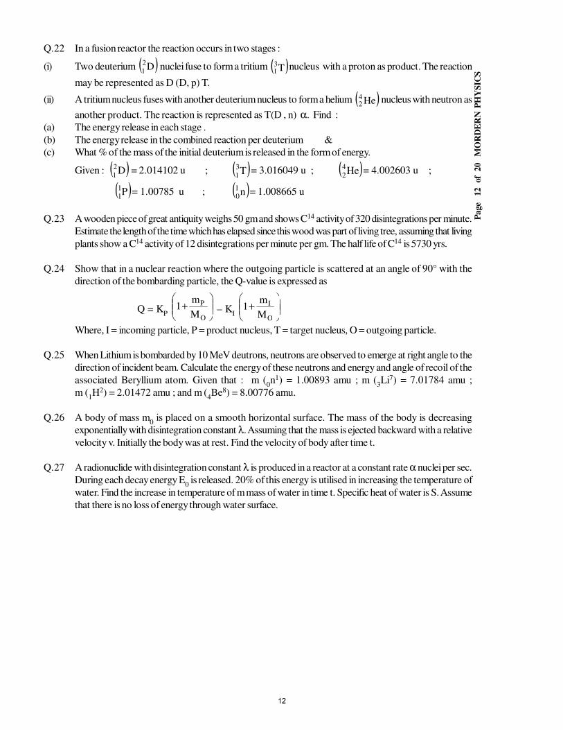
Pa
ge
12
of 2
0
MO
RD
ER
N P
HY
SIC
S
Q.22 In a fusion reactor the reaction occurs in two stages :
(i) Two deuterium ( )D21
nuclei fuse to form a tritium ( )T31
nucleus with a proton as product. The reaction
may be represented as D (D, p) T.
(ii) A tritium nucleus fuses with another deuterium nucleus to form a helium ( )He42
nucleus with neutron as
another product. The reaction is represented as T(D , n) α. Find :
(a) The energy release in each stage .
(b) The energy release in the combined reaction per deuterium &
(c) What % of the mass of the initial deuterium is released in the form of energy.
Given : ( )D2
1 = 2.014102 u ; ( )T3
1= 3.016049 u ; ( )He4
2= 4.002603 u ;
( )P11
= 1.00785 u ; ( )n10
= 1.008665 u
Q.23 A wooden piece of great antiquity weighs 50 gm and shows C14 activity of 320 disintegrations per minute.
Estimate the length of the time which has elapsed since this wood was part of living tree, assuming that living
plants show a C14 activity of 12 disintegrations per minute per gm. The half life of C14 is 5730 yrs.
Q.24 Show that in a nuclear reaction where the outgoing particle is scattered at an angle of 90° with the
direction of the bombarding particle, the Q-value is expressed as
Q = KP
+
O
P
M
m1 – K
I
+
O
I
M
m1
Where, I = incoming particle, P = product nucleus, T = target nucleus, O = outgoing particle.
Q.25 When Lithium is bombarded by 10 MeV deutrons, neutrons are observed to emerge at right angle to the
direction of incident beam. Calculate the energy of these neutrons and energy and angle of recoil of the
associated Beryllium atom. Given that : m (0n1) = 1.00893 amu ; m (
3Li7) = 7.01784 amu ;
m (1H2) = 2.01472 amu ; and m (
4Be8) = 8.00776 amu.
Q.26 A body of mass m0 is placed on a smooth horizontal surface. The mass of the body is decreasing
exponentially with disintegration constant λ. Assuming that the mass is ejected backward with a relative
velocity v. Initially the body was at rest. Find the velocity of body after time t.
Q.27 A radionuclide with disintegration constant λ is produced in a reactor at a constant rate α nuclei per sec.
During each decay energy E0 is released. 20% of this energy is utilised in increasing the temperature of
water. Find the increase in temperature of m mass of water in time t. Specific heat of water is S. Assume
that there is no loss of energy through water surface.
12
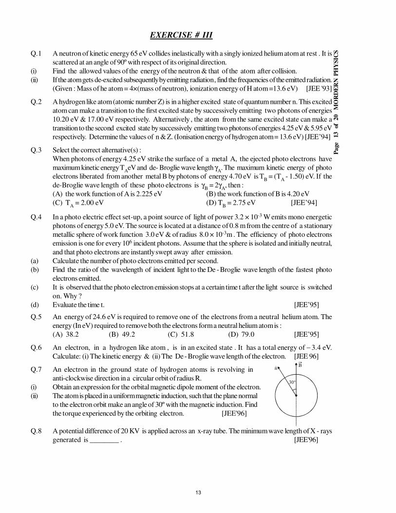
Pa
ge
13
of 2
0
MO
RD
ER
N P
HY
SIC
S
EXERCISE # III
Q.1 A neutron of kinetic energy 65 eV collides inelastically with a singly ionized helium atom at rest . It is
scattered at an angle of 90º with respect of its original direction.
(i) Find the allowed values of the energy of the neutron & that of the atom after collision.
(ii) If the atom gets de-excited subsequently by emitting radiation , find the frequencies of the emitted radiation.
(Given : Mass of he atom = 4×(mass of neutron), ionization energy of H atom =13.6 eV) [JEE '93]
Q.2 A hydrogen like atom (atomic number Z) is in a higher excited state of quantum number n. This excited
atom can make a transition to the first excited state by successively emitting two photons of energies
10.20 eV & 17.00 eV respectively. Alternatively , the atom from the same excited state can make a
transition to the second excited state by successively emitting two photons of energies 4.25 eV & 5.95 eV
respectively. Determine the values of n & Z. (Ionisation energy of hydrogen atom = 13.6 eV) [JEE’94]
Q.3 Select the correct alternative(s) :
When photons of energy 4.25 eV strike the surface of a metal A, the ejected photo electrons have
maximum kinetic energy TAeV and de- Broglie wave length γ
A. The maximum kinetic energy of photo
electrons liberated from another metal B by photons of energy 4.70 eV is TB = (T
A - 1.50) eV. If the
de-Broglie wave length of these photo electrons is γB = 2γ
A, then :
(A) the work function of A is 2.225 eV (B) the work function of B is 4.20 eV
(C) TA = 2.00 eV (D) T
B = 2.75 eV [JEE’94]
Q.4 In a photo electric effect set-up, a point source of light of power 3.2 × 10⁻³ W emits mono energetic
photons of energy 5.0 eV. The source is located at a distance of 0.8 m from the centre of a stationary
metallic sphere of work function 3.0 eV & of radius 8.0 × 10⁻³m . The efficiency of photo electrons
emission is one for every 106 incident photons. Assume that the sphere is isolated and initially neutral,
and that photo electrons are instantly swept away after emission.
(a) Calculate the number of photo electrons emitted per second.
(b) Find the ratio of the wavelength of incident light to the De - Broglie wave length of the fastest photo
electrons emitted.
(c) It is observed that the photo electron emission stops at a certain time t after the light source is switched
on. Why ?
(d) Evaluate the time t. [JEE’95]
Q.5 An energy of 24.6 eV is required to remove one of the electrons from a neutral helium atom. The
energy (In eV) required to remove both the electrons form a neutral helium atom is :
(A) 38.2 (B) 49.2 (C) 51.8 (D) 79.0 [JEE’95]
Q.6 An electron, in a hydrogen like atom , is in an excited state . It has a total energy of − 3.4 eV.
Calculate: (i) The kinetic energy & (ii) The De - Broglie wave length of the electron. [JEE 96]
Q.7 An electron in the ground state of hydrogen atoms is revolving in
anti-clockwise direction in a circular orbit of radius R.
(i) Obtain an expression for the orbital magnetic dipole moment of the electron.
(ii) The atom is placed in a uniform magnetic induction, such that the plane normal
to the electron orbit make an angle of 30º with the magnetic induction. Find
the torque experienced by the orbiting electron. [JEE'96]
Q.8 A potential difference of 20 KV is applied across an x-ray tube. The minimum wave length of X - rays
generated is ________ . [JEE'96]
13
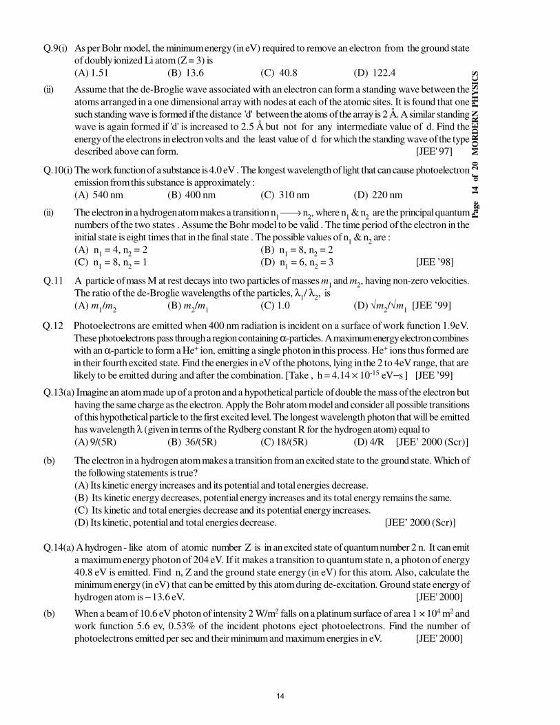
Pa
ge
14
of 2
0
MO
RD
ER
N P
HY
SIC
S
Q.9(i) As per Bohr model, the minimum energy (in eV) required to remove an electron from the ground state
of doubly ionized Li atom (Z = 3) is
(A) 1.51 (B) 13.6 (C) 40.8 (D) 122.4
(ii) Assume that the de-Broglie wave associated with an electron can form a standing wave between the
atoms arranged in a one dimensional array with nodes at each of the atomic sites. It is found that one
such standing wave is formed if the distance 'd' between the atoms of the array is 2 Å. A similar standing
wave is again formed if 'd' is increased to 2.5 Å but not for any intermediate value of d. Find the
energy of the electrons in electron volts and the least value of d for which the standing wave of the type
described above can form. [JEE' 97]
Q.10(i) The work function of a substance is 4.0 eV . The longest wavelength of light that can cause photoelectron
emission from this substance is approximately :
(A) 540 nm (B) 400 nm (C) 310 nm (D) 220 nm
(ii) The electron in a hydrogen atom makes a transition n1 → n
2, where n
1 & n
2 are the principal quantum
numbers of the two states . Assume the Bohr model to be valid . The time period of the electron in the
initial state is eight times that in the final state . The possible values of n1 & n
2 are :
(A) n1 = 4, n
2 = 2 (B) n
1 = 8, n
2 = 2
(C) n1 = 8, n
2 = 1 (D) n
1 = 6, n
2 = 3 [JEE ’98]
Q.11 A particle of mass M at rest decays into two particles of masses m1 and m
2, having non-zero velocities.
The ratio of the de-Broglie wavelengths of the particles, λ1/ λ
2, is
(A) m1/m
2(B) m
2/m
1(C) 1.0 (D) √m
2/√m
1 [JEE ’99]
Q.12 Photoelectrons are emitted when 400 nm radiation is incident on a surface of work function 1.9eV.
These photoelectrons pass through a region containing α-particles. A maximum energy electron combines
with an α-particle to form a He+ ion, emitting a single photon in this process. He+ ions thus formed are
in their fourth excited state. Find the energies in eV of the photons, lying in the 2 to 4eV range, that are
likely to be emitted during and after the combination. [Take , h = 4.14 × 10⁻¹⁵ eV−s ] [JEE ’99]
Q.13(a) Imagine an atom made up of a proton and a hypothetical particle of double the mass of the electron but
having the same charge as the electron. Apply the Bohr atom model and consider all possible transitions
of this hypothetical particle to the first excited level. The longest wavelength photon that will be emitted
has wavelength λ (given in terms of the Rydberg constant R for the hydrogen atom) equal to
(A) 9/(5R) (B) 36/(5R) (C) 18/(5R) (D) 4/R [JEE’ 2000 (Scr)]
(b) The electron in a hydrogen atom makes a transition from an excited state to the ground state. Which of
the following statements is true?
(A) Its kinetic energy increases and its potential and total energies decrease.
(B) Its kinetic energy decreases, potential energy increases and its total energy remains the same.
(C) Its kinetic and total energies decrease and its potential energy increases.
(D) Its kinetic, potential and total energies decrease. [JEE’ 2000 (Scr)]
Q.14(a) A hydrogen - like atom of atomic number Z is in an excited state of quantum number 2 n. It can emit
a maximum energy photon of 204 eV. If it makes a transition to quantum state n, a photon of energy
40.8 eV is emitted. Find n, Z and the ground state energy (in eV) for this atom. Also, calculate the
minimum energy (in eV) that can be emitted by this atom during de-excitation. Ground state energy of
hydrogen atom is − 13.6 eV. [JEE' 2000]
(b) When a beam of 10.6 eV photon of intensity 2 W/m2 falls on a platinum surface of area 1 × 10⁴ m2 and
work function 5.6 ev, 0.53% of the incident photons eject photoelectrons. Find the number of
photoelectrons emitted per sec and their minimum and maximum energies in eV. [JEE' 2000]
14
Pa
ge
15
of 2
0
MO
RD
ER
N P
HY
SIC
S
Q.15 The potential difference applied to an X - ray tube is 5 kV and the current through it is 3.2 mA. Then the
number of electrons striking the target per second is [JEE' 2002 (Scr.)]
(A) 2 × 10¹⁶ (B) 5 × 10¹⁶ (C) 1 × 10¹⁷ (D) 4 × 10¹⁵
Q.16 A Hydrogen atom and Li++ ion are both in the second excited state. If lH
and lLi
are their respective
electronic angular momenta, and EH and E
Li their respective energies, then
(A) lH > l
Li and |E
H| > |E
Li| (B) l
H = l
Li and |E
H| < |E
Li|
(C) lH = l
Li and |E
H| > |E
Li| (D) l
H < l
Li and |E
H| < |E
Li| [JEE 2002 (Scr)]
Q.17 A hydrogen like atom (described by the Bohr model) is observed to emit six wavelengths, originating
from all possible transition between a group of levels. These levels have energies between – 0.85 eV and
– 0.544 eV (including both these values)
(a) Find the atomic number of the atom.
(b) Calculate the smallest wavelength emitted in these transitions. [JEE' 2002]
Q.18 Two metallic plates A and B each of area 5 × 10⁻⁴ m2, are placed at a separation of 1 cm. Plate B carries
a positive charge of 33.7 × 10⁻¹² C. A monochromatic beam of light, with photons of energy 5 eV each,
starts falling on plate A at t = 0 so that 1016 photons fall on it per square meter per second. Assume that
one photoelectron is emitted for every 106 incident photons. Also assume that all the emitted photoelectrons
are collected by plate B and the work function of plate A remains constant at the value 2 eV. Determine
(a) the number of photoelectrons emitted up to t = 10 sec.
(b) the magnitude of the electric field between the plates A and B at t = 10 s and
(c) the kinetic energy of the most energetic photoelectron emitted at t = 10 s when it reaches plate B.
(Neglect the time taken by photoelectron to reach plate B) [JEE' 2002]
Q.19 The attractive potential for an atom is given by v = v0 ln( )0r/r , v
0 and r
0 are constant and r is the radius
of the orbit. The radius r of the nth Bohr's orbit depends upon principal quantum number n as :
(A) r ∝ n (B) r ∝ 1/n2 (C) r ∝ n2 (D) r ∝ 1/n
[JEE' 2003 (Scr)]
Q.20 Frequency of a photon emitted due to transition of electron of a certain elemrnt from L to K shell is
found to be 4.2 × 10¹⁸ Hz. Using Moseley's law, find the atomic number of the element, given that the
Rydberg's constant R = 1.1 × 10⁷ m–1. [JEE' 2003]
Q.21 In a photoelctric experiment set up, photons of energy 5 eV falls on the cathode having work function 3 eV.
(a) If the saturation current is iA = 4µA for intensity 10–5 W/m2, then plot a graph between anode potential
and current.
(b) Also draw a graph for intensity of incident radiation of 2 × 10⁻⁵ W/m2 ? [JEE' 2003]
Q.22 A star initially has 1040 deutrons. It produces energy via, the processes 1H2 +
1H2 →
1H3 + p
& 1H2 +
1H3 →
2He4 + n. If the average power radiated by the star is 1016 W, the deuteron supply of
the star is exhausted in a time of the order of : [JEE ’93]
(A) 106 sec (B) 108 sec (C) 1012 sec (D) 1016 sec
Q.23 A small quantity of solution containing 24Na radionuclide (half life 15 hours) of activity 1.0 microcurie
is injected into the blood of a person. A sample of the blood of volume 1 cm3 taken after 5 hours
shows an activity of 296 disintegrations per minute. Determine the total volume of blood in the body of
the person. Assume that the radioactive solution mixes uniformly in the blood of the person.
(1 Curie = 3.7 × 10¹⁰ disintegrations per second ) [JEE’94]
Q.24(i) Fast neutrons can easily be slowed down by :
(A) the use of lead shielding (B) passing them through water
(C) elastic collisions with heavy nuclei (D) applying a strong electric field
15
Pa
ge
16
of 2
0
MO
RD
ER
N P
HY
SIC
S
(ii) Consider α − particles , β − particles & γ rays , each having an energy of 0.5 MeV . Increasing order
of penetrating powers , the radiations are : [JEE’94]
(A) α , β , γ (B) α , γ , β (C) β , γ , α (D) γ , β , α
Q.25 Which of the following statement(s) is (are) correct ? [JEE'94]
(A) The rest mass of a stable nucleus is less than the sum of the rest masses of its separated nucleons.
(B) The rest mass of a stable nucleus is greater than the sum of the rest masses of its separated nucleons.
(C) In nuclear fusion, energy is released by fusion two nuclei of medium mass (approximately 100 amu).
(D) In nuclear fission, energy is released by fragmentation of a very heavy nucleus.
Q.26 The binding energy per nucleon of 16O is 7.97 MeV & that of 17O is 7.75 MeV . The energy in MeV
required to remove a neutron from 17O is : [JEE’95]
(A) 3.52 (B) 3.64 (C) 4.23 (D) 7.86
Q.27 At a given instant there are 25 % undecayed radio − active nuclei in a sample. After 10 sec the number
of undecayed nuclei remains to 12.5 % . Calculate : [JEE 96]
(i) mean − life of the nuclei and
(ii) The time in which the number of undecayed nuclear will further reduce to 6.25 % of the reduced number.
Q.28 Consider the following reaction ; 2H1 + 2H
1 = 4He
2 + Q . [JEE 96]
Mass of the deuterium atom = 2.0141 u ; Mass of the helium atom = 4.0024 u
This is a nuclear ______ reaction in which the energy Q is released is ______ MeV.
Q.29(a)The maximum kinetic energy of photoelectrons emitted from a surface when photons of energy 6 eV
fall on it is 4 eV. The stopping potential in Volts is :
(A) 2 (B) 4 (C) 6 (D) 10
(b) In the following, column I lists some physical quantities & the column II gives approx. energy valuesassociated with some of them. Choose the appropriate value of energy from column II for each of the
physical quantities in column I and write the corresponding letter A, B, C etc. against the number (i),(ii), (iii), etc. of the physical quantity in the answer book. In your answer, the sequence of column I
should be maintained .
Column I Column II
(i) Energy of thermal neutrons (A) 0.025 eV(ii) Energy of X−rays (B) 0.5 eV
(iii) Binding energy per nucleon (C) 3 eV(iv) Photoelectric threshold of metal (D) 20 eV
(E) 10 keV
(F) 8 MeV
(c) The element Curium Cm24896 has a mean life of 1013 seconds. Its primary decay modes are spontaneous
fission and α decay, the former with a probability of 8% and the latter with a probability of 92%. Each
fission releases 200 MeV of energy . The masses involved in α decay are as follows :
He&u064100.244Pu,u072220.248Cm 42
24494
24896
== .u002603.4=Calculate the power output from a sample of 1020 Cm atoms. (l u = 931 MeV/c2) [JEE'97]
Q.30 Select the correct alternative(s) . [JEE '98]
(i) Let mp be the mass of a proton, m
n the mass of a neutron, M
1 the mass of a 10
20 Ne nucleus & M2 the
mass of a 2040Ca nucleus. Then :
(A) M2 = 2 M
1(B) M
2 > 2 M
1 (C) M
2 < 2 M
1(D) M
1 < 10 (m
n + m
p)
(ii) The half − life of 131I is 8 days. Given a sample of 131I at time t = 0, we can assert that :
(A) no nucleus will decay before t = 4 days (B) no nucleus will decay before t = 8 days
(C) all nuclei will decay before t = 16 days (D) a given nucleus may decay at any time after t = 0.
16
Pa
ge
17
of 2
0
MO
RD
ER
N P
HY
SIC
S
Q.31 Nuclei of a radioactive element A are being produced at a constant rate α . The element has a decay
constant λ . At time t = 0, there are N0 nuclei of the element.
(a) Calculate the number N of nuclei of A at time t .
(b) If α=2N0λ, calculate the number of nuclei of A after one halflife of A & also the limiting value of N as t→∞.
[JEE '98]
Q.32(a) Binding energy per nucleon vs. mass number curve for
nuclei is shown in the figure. W, X, Y and Z are four
nuclei indicated on the curve. The process that would
release energy is
(A) Y → 2Z (B) W → X + Z
(C) W → 2Y (D) X → Y + Z
(b) Order of magnitude of density of Uranium nucleus is, [mP = 1.67 × 10⁻²⁷ kg]
(A) 1020 kg/m3 (B) 1017kg/m3 (C) 1014kg/m3 (D) 1011kg/m3
(c) 22Ne nucleus, after absorbing energy, decays into two α−particles and an unknown nucleus. The unknown
nucleus is
(A) nitrogen (B) carbon (C) boron (D) oxygen
(d) Which of the following is a correct statement?
(A) Beta rays are same as cathode rays
(B) Gamma rays are high energy neutrons.
(C) Alpha particles are singly ionized helium atoms
(D) Protons and neutrons have exactly the same mass
(E) None
(e) The half−life period of a radioactive element X is same as the mean−life time of another radioactive
element Y. Initially both of them have the same number of atoms. Then
(A) X & Y have the same decay rate initially (B) X & Y decay at the same rate always
(C) Y will decay at a faster rate than X (D) X will decay at a faster rate than Y [JEE '99]
Q.33 Two radioactive materials X1 and X
2 have decay constants 10λ and λ respectively. If initially they have the
same number of nuclei, then the ratio of the number of nuclei of X1 to that of X
2 will be 1/e after a time
(A) 1/(10λ) (B) 1/(11λ) (C) 11/(10λ) (D) 1/(9λ) [JEE ' 2000 (Scr)]
Q.34 The electron emitted in beta radiation originates from [JEE’2001(Scr)]
(A) inner orbits of atoms (B) free electrons existing in nuclei
(C) decay of a neutron in a nucleus (D) photon escaping from the nucleus
Q.35 The half - life of 215At is 100 µs. The time taken for the radioactivity of a sample of 215At to decay to
1/16th of its initial value is [JEE 2002 (Scr)]
(A) 400 µs (B) 6.3 µs (C) 40 µs (D) 300 µs
Q.36 Which of the following processes represents a gamma - decay? [JEE 2002 (Scr)]
(A) AXZ + γ → AX
Z – 1 + a + b (B) AX
Z + 1n
0 → A– 3X
Z –2 + c
(C) AXZ → AX
Z + f (D) AX
Z + e
–1 → AX
Z – 1 + g
Q.37 The volume and mass of a nucleus are related as [JEE 2003 (Scr)]
(A) v ∝ m (B) v ∝ 1/m (C) v ∝ m2 (D) v ∝ 1/m2
Q.38 The nucleus of element X (A = 220) undergoes α-decay. If Q-value of the reaction is 5.5 MeV, then the
kinetic energy of α-particle is : [JEE 2003 (Scr)]
(A) 5.4 MeV (B) 10.8 MeV (C) 2.7 MeV (D) None
Q.39 A radioactive sample emits n β-particles in 2 sec. In next 2 sec it emits 0.75 n β-particles, what is the
mean life of the sample? [JEE 2003]
17
Pa
ge
18
of 2
0
MO
RD
ER
N P
HY
SIC
S
Q.40 The wavelength of Kα X-ray of an element having atomic number z = 11 is λ . The wavelength of KαX-ray of another element of atomic number z' is 4λ. Then z' is
(A) 11 (B) 44 (C) 6 (D) 4 [JEE' 2005 (Scr)]
Q.41 A photon of 10.2 eV energy collides with a hydrogen atom in ground state inelastically. After few
microseconds one more photon of energy 15 eV collides with the same hydrogen atom.Then what can
be detected by a suitable detector.
(A) one photon of 10.2 eV and an electron of energy 1.4 eV
(B) 2 photons of energy 10.2 eV
(C) 2 photons of energy 3.4 eV
(D) 1 photon of 3.4 eV and one electron of 1.4 eV [JEE' 2005 (Scr)]
Q.42 Helium nuclie combines to form an oxygen nucleus. The binding energy per nucleon of oxygen nucleus is
if m0 = 15.834 amu and m
He = 4.0026 amu
(A) 10.24 MeV (B) 0 MeV (C) 5.24 MeV (D) 4 MeV
[JEE' 2005 (Scr)]
Q.43 The potential energy of a particle of mass m is given by
>≤≤=
1x01x0E
)x(V 0
λ1 and λ
2 are the de-Broglie wavelengths of the particle, when 0 ≤ x ≤ 1 and x > 1 respectively. If the
total energy of particle is 2E0, find λ
1/λ
2. [JEE 2005]
Q.44 Highly energetic electrons are bombarded on a target of an element containing 30 neutrons. The ratio of
radii of nucleus to that of helium nucleus is (14)1/3. Find
(a) atomic number of the nucleus
(b) the frequency of Kα line of the X-ray produced. (R = 1.1× 10⁷ m–1 and c = 3 × 10⁸ m/s)
[JEE 2005]
Q.45 Given a sample of Radium-226 having half-life of 4 days. Find the probability, a nucleus disintegrates
within 2 half lives.
(A) 1 (B) 1/2 (C) 3/4 (D) 1/4 [JEE 2006]
Q.46 The graph between 1/λ and stopping potential (V) of three metals
having work functions φ1, φ
2 and φ
3 in an experiment of photo-
electric effect is plotted as shown in the figure. Which of the
following statement(s) is/are correct? [Here λis the wavelength of the incident ray].
(A) Ratio of work functions φ1 : φ
2 : φ
3 = 1 : 2 : 4
(B) Ratio of work functions φ1 : φ
2 : φ
3 = 4 : 2 : 1
(C) tan θ is directly proportional to hc/e, where h is Planck’s constant and c is the speed of light
(D) The violet colour light can eject photoelectrons from metals 2 and 3. [JEE 2006]
Q.47 In hydrogen-like atom (z = 11), nth line of Lyman series has wavelength λ equal to the de-Broglie’s
wavelength of electron in the level from which it originated. What is the value of n? [JEE 2006]
Q.48 Match the following Columns [JEE 2006]
Column 1 Column 2
(A) Nuclear fusion (P) Converts some matter into energy
(B) Nuclear fission (Q) Generally occurs for nuclei with low atomic number
(C) β–decay (R) Generally occurs for nuclei with higher atomic number
(D) Exothermic nuclear reaction (S) Essentially proceeds by weak nuclear forces
18
ANSWER KEYEXERCISE # I
Q.1 885 Q.2 (a) 2.25eV, (b) 4.2eV, (c) 2.0 eV, 0.5 eV Q.3 (a) 0.6 volt, (b) 2.0 mA
Q.4 when the potential is steady, photo electric emission just stop when hυ = (3 + 1)eV = 4.0 eV
Q.5 5.76 × 10⁻¹¹ A Q.6 15/8 V Q.7 487.06 nm Q.8 4.26 m/s, 13.2 eV
Q.9 7 : 36 Q.10 22.8 nm Q.1121
21
λ+λ
λλQ.12 18/(5R)
Q.13 1.257 × 10⁻²³ Am2 Q.14 2.48 ×10⁻¹² m Q.1516
5,
π80
1020
Q.16 2 eV, 6.53 × 10⁻³⁴ J-s
Q.17 5 Q.18 (i) 5, 16.5 eV, 36.4 A, 340 eV, – 680 eV, π2
h 1.06 × 10–111 m
Q.19 z = 3, n = 7 Q.20 54.4 eV Q.21 n = 3, 3 : 1 Q.22 23.6 MeV
Q.23 ( 2/1T = 10.8 sec) Q.24 (i) K40
19 → Ar4018
+ +1
e0 + ν (ii) 4.2 × 10⁹ years
Q.25 t = τ
2n
5n
l
lQ.26 18
1038 × sec Q.27 1.14 × 10¹⁸ sec Q.28 – h/eEt2
EXERCISE # II
Q.1 8IhR/3C C15
hRI38Q.2 4.8 × 10¹⁶, 4.0 cm Q.3 1.99 eV, 0.760 V
Q.4 1.1 × 10¹² Q.5 (i) 4125Å, (ii) 13.2 µA
Q.6 (i) 1.33 × 10¹⁶ photons/m2 − s ; 0.096 µÅ (ii) 2.956 × 10¹⁵ photons/m2s ; 0.0213 µA (iii) 1.06 volt
Q.7 (i) 5/16 photon/sec, (ii) 5/1600 electrons/sec Q.8 λdeutron
= λneutron
= 8.6 pm
Q.9 λ = 22
21
212
λ+λ
λλQ.10 3.1 × 10⁶ m/s Q.11 (i) 2 ; (ii) 23.04 ×10⁻¹⁹J ; (iii) 4 → 1 , 4 → 3
Q.12 11.24 eV Q.13 6.8 eV, 5 × 10¹⁵ Hz Q.14 489.6 eV, 25.28 Å
Q.15 (i) – r
e
8
1 2
0πε, (ii)
3/1
30
2e
0r
trC31r
− , (iii) 10–10 ×
81
100 sec
Q.16 (i) 1.875 × 10⁴ V, (ii) 2.7 × 10⁻¹⁵ J, (iii) 0.737 Å, (iv) 2.67 × 10⁻¹⁵ J
Q.17 6.04 × 10⁹ yrs Q.18 4.87 MeV Q.19 3.3 × 10⁻⁶ gQ.20 1.7 × 10¹⁰ years Q.21 7.01366 amu
Q.22 (a) 4 MeV , 17.6 (b) 7.2 MeV (c) 0.384 % Q.23 5196 yrs
Q.25 Energy of neutron = 19.768 MeV ; Energy of Beryllium = 5.0007 MeV;
Angle of recoil = tan–1(1.034) or 46°
Q.26 v = uλt Q.27 ∆T = Sm
)e1(tE2.0 t0
−λα
−α λ−
19
EXERCISE # III
Q.1 (i) Allowed values of energy of neutron = 6.36 eV and 0.312 eV ; Allowed values of energy of He atom
= 17.84 eV and 16.328 eV , (ii) 18.23 x 10¹⁵ Hz , 9.846 x 10¹⁵ Hz , 11.6 x 10¹⁵ Hz
Q.2 n = 6, Z = 3 Q.3 B, C Q.4 (a) 105 s–1 ; (b) 286.18 ; (d) 111 s
Q.5 D Q.6 (i) KE = 3.4 eV, (ii) λ = 6.66 Å Q.7 (i) m4
he
π (ii)
m8
ehB
πQ.8 0.61 Å Q.9 (i) D, (ii) KE ≅ 151 eV, d
least = 0.5 Å
Q.10 (i) C (ii) A, D Q.11 C
Q.12 during combination = 3.365 eV; after combination = 3.88 eV (5 → 3) & 2.63 eV (4 → 3)
Q.13 (a) C, (b) A
Q.14 (a) n = 2, z = 4; G.S.E. − 217.6 eV; Min. energy = 10.58 eV; (b) 6.25×10¹⁹ per sec, 0, 5 eV
Q.15 A Q.16 B Q.17 3, 4052.3 nm Q.18 5×10⁷, 2000N/C, 23 eV
Q.19 A Q.20 z = 42 Q.21
Q.22 C Q.23 6 litre Q.24 (i) B, (ii) A Q.25 A , D
Q.26 C Q.27 (i) t1/2
= 10 sec. , tmeans
= 14.43 s (ii) 40 seconds
Q.28 Fusion , 24 Q.29 (a) B, (b) (i) − A, (ii) − E, (iii) − F, (iv) − C, (c) ≅ 33.298 µW
Q.30 (i) C, D (ii) D Q.31 (a) N = 1
λ [α (1 − e −λt )+ λ N
0 e−λt] (b)
3
2
0N , 2 N
0
Q.32 (a) C ; (b) B ; (c) B ; (d) E ; (e) C Q.33 D
Q.34 C Q.35 A Q.36 C Q.37 A
Q.38 A Q.39 1.75n = N0(1 – e–4λ), 6.95 sec,
3
4n
2
l
Q.40 C
Q.41 A Q.42 A Q.43 2 Q.44 ν = 1.546 × 10¹⁸ Hz
Q.45 C Q.46 A,C Q.47 n = 24
Q.48 (A) P, Q; (B) P, R; (C) S, P; (D) P, Q, R
20
STUDY PACKAGE
Target: IIT-JEE (Advanced)
SUBJECT: PHYSICS
TOPIC: XII P11. Semiconductors Electronics
Index:
1. Key Concepts
2. Exercise I
3. Exercise II
4. Exercise III
5. Exercise IV
6. Answer Key
7. 34 Yrs. Que. from IIT-JEE
8. 10 Yrs. Que. from AIEEE
1
Electronics
The study of matter in the solid state and its physical properties has contributed a lot to modern living–
particularly, the science of electronics.
Solids may be crystalline or amorphous –crystalline solids have long-range order in their structure while
amorphous solids do not have such order. Here we will deal with crystalline solids only.
Crystalline solids & their electronic properties
A crystalline solid is built around a lattice, the regular, repeating mathematical points extending throughout
space. The forces responsible for the regular arrangement of atoms in a lattice are similar to those in
molecular bonds – covalent and ionic. A third type crystalline bond is a metallic bond: one or more of the
outermost electrons in each atom become detached from the parent atom and are free to move throughout
the crystal. These electrons are known as “free electrons”, and are responsible for the conduction of
electricity by metals.
Band structure of solids
As isolated atoms are brought together to form a solid, interactions occur between neighbouring atoms.
The attractive and repulsive forces between atoms find a proper balance when the proper inter-atomic
spacing is reached. As this process occurs, there are important changes in the electronic energy levels
and these changes lead to the varied electrical properties of solids.
An electron moving within a crystal lattice is subjected to a periodic potential due to the ionic cores
present in the regular arrangement of the lattice. This is very different from the potential feld by an
electron within a hydrogen atom. The energy levels (or the single atom: they are distributed in a band like
structure, with gaps in between. The highest energy band wave functions are highly delocalized: an
electron in one of these bands tends to be free enough to move over the entire body of the crystal. This
band is known as a conduction band. The wave function belonging to lower bands are not so highly
localised, they are localised to within a few neighbouring atoms of the lattice. The electrons in these
bands are responsible for the formation of inter-atomic bonds: the band is referred to as the valence
band and the electrons, valence electrons.’
Energy bands, that are lower in energy than the valence band, have progressively decreasing widths and
have properties similar to atomic levels. Their wave functions a localized to a single atom and they are,
therefore, tightly bound.
Metals, insulators and semiconductors
The energy gap between the lowest level of the conduction band and the highest level of the valence
band is known as the band gap (Eg). The band gap (E
g) and the nature of the filling of the energy levels
(according to the Pauli Exclusion principle) are cheifly respeonsible for the electrical properties of solids.
When there exists a large number of electrons within the conduction band as a result of the filling process,
this leads to conduction. Another reason for the existence of electrons within the conduction band is the
thermal excitation of electrons from the valence band.
The probability of electronic at a temperature T(in Kelvin) varies as the factor e–Eg/2kT, where E0 is the
band gap and k is Boltzmann’s constant. Thus materials having very small gaps (E0 < 1 meV) behave as
conductors, while those having large band gaps (Eg < 5 eV) behave as insulators at ordinary temperatures.
Materials (like crystalline Si, Ge) having band gaps Eg–1eV behave as semiconductors at ordinary
temperatures.
2
As the temperature is raised in a semiconductor, electrons from the valence band pick up thermal excitation
from atomic motion within the lattice and this leads to a transition to the conduction band, if sufficient
energy is transferred to the electron.
For each electron that transits to the conduction band, a valency is left within the valence band. This
vacancy, referred to as a hole, helps in conduction as well. When an external electric field is applied to a
semiconductor sample, the electrons within the conduction band experience a force proportional to the
electric field.
F = qeE, where q
e is the electronic charge.
The acceleration of the electron is,
a = m
qe E, m being the effective mass of the electron in the conduction band.
Due to collisions between the electron and and ionic cores within the lattice, this motion leads to an
effective uniform drift velocity for electrons within the electric field.
The electron accelerates for a time τ, the collision time, before it loses its energy to the lattice in a
collision. In this model (the Drude–Lorenz model), the average drift velocity of the electron is
vd = aτ =
e
e
m
q EE
If there are ne electrons per unit volume, the current density j is given by
j = neq
ev
d =
e
2
ee
m
qn τE
≡ σE (by definition), Further, vd =
e
e
m
q τE = µ
eE (by definition)
where µe is the ‘mobility’ of the electron in the conduction band.
Conduction occurs also in the valence band. Here, the electrons ‘hop’ from one vacancy (“hole”) to
another in the electric field E, causing an electric current. This current may be thought of as due to the
motion of “hole” within the valence band, the “holes” imagined to possess a positive charge equal in
magnitude to that on an electron.
This accounts for the fact that the “holes” move in an opposite direction to electrons within the valence
band.
The net current density within the semiconductor is given by:
j = Em
qn
m
qn
n
nen
e
eee
+
ττ 22
= qe(n
eµ
e + n
nµ
n)E
where nh and µ
h are the concentration of holes and hole mobility, respectively, within thevalence band.
∴ σ = qe(n
eµ
e + n
hµ
h)
Illustration 1: Germanium has a band gap of 0.67 eV. Calculate the value of the quantity e–Eg/kT, which is
related to the probability of a transition of an electron from the valence band to the conduction band, for
two temperatures at 270C and 1270C.
Sol: The band gap of Ge = 0.67 eV
At T = 300 K (or 273 + 27)
3
kBT =
11600
1 x 300
≈ 0.026 eV & at T = 400 K (1270C)
kBT ≈ 0.0345 eV
e–Eg/kT = 6.4 x 10⁻¹² at 270C
and 3.7 x 10⁻⁹ at 1270C
Intrinsic and Extrinsic Semiconductors
For intrinsic semiconductors, the concentration of electrons within the conduction band (ne) equals that
of holes within the valence band (nh)
Intrinsic semiconductors are usually those which do not have any impurities within them. At absolute zero
(T = 0), these semiconductors do not have any electorns in the conduction band or holes within the
valence band examples are pure crystalline Si, Ge, Ga, As, In Sb, etc.
Extrinsic semiconduction occurs due to the introduction of excess holes or, electrons into a semiconductor
(Si for example). This is done by introducing microscopic quantities of Group V elements (P, As) as
impurities into the Si – lattice. These impurities are added in very small concentrations so that they do not
change the Si-lattice. Being pentavalent, there exists an excess electron (in addition to the four, which
form bonds) in P0. An energy level P (or As) lies just below the conduction band of Si.
The excess electron (in this donor level) of P is immediately transferred to the conduction band of Si: this
results in an increase in the concentration of conduction electrons – ne. However, this also results in a
reduction in the number of holes, such that,
nen
h = n
1
2
This type of Si with excess electrons is known as n-type Si.
Addition of small quantities of acceptor type impurities (trivalent group III elements like B) leads to an
empty ‘acceptor’ level just above the filled valence band. This leads to electrons getting transferred from
the valence band into this acceptor level, and thus, the introduction of holes into the valence band.
The relation nen
h = n
1
2, also holds good here.
The concentration of electrons in the conduction band gets correspondingly reduced. Such semiconductors
are known as p-type semiconductors.
Illustration 2: A semiconductor has an electron concentration of 0.45 x 10¹²/ m3 and a hole concentration of 5
x 1020 / m3. Find its conductivity. ( µe = 0.135 m2/V-S, µ
h = 0.048 m2/V-S).
Sol: The conductivity, σ = e(neµ
e + n
hµ
h)
= 1.6 x 10⁻¹⁹ (o.45 x 1022 x 0.135 + 5 x 1020 x 0.048)
= 3.84 Ω -1-m-1.
Exercise 1: A silicon sample is made into a p-type semiconductor by doping, on an average on Indium atom
per 5 x 10⁷ silicon atoms. If number density of atoms in the silicon sample is 5 x 1028 atoms/m3 then find
the number density of Indium atoms in silicon per cm3.
4
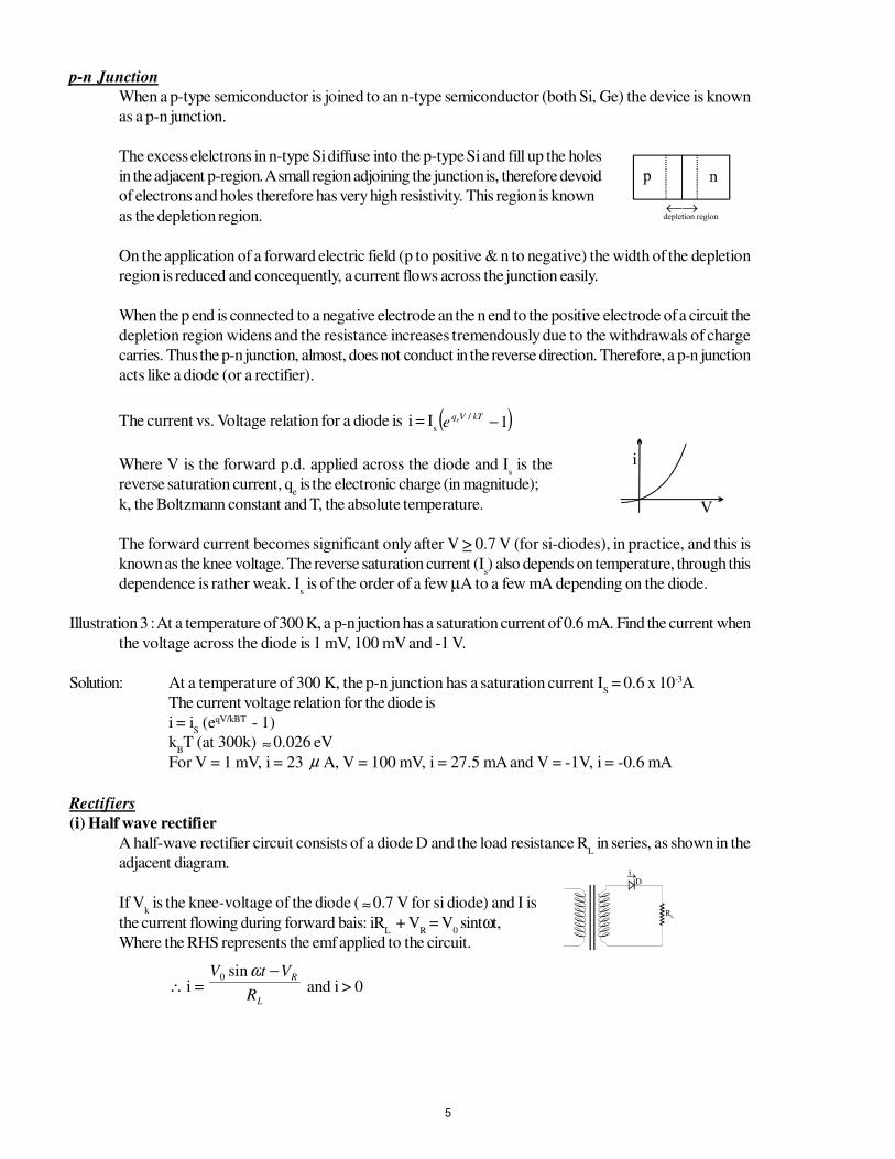
p-n Junction
When a p-type semiconductor is joined to an n-type semiconductor (both Si, Ge) the device is known
as a p-n junction.
The excess elelctrons in n-type Si diffuse into the p-type Si and fill up the holes
in the adjacent p-region. A small region adjoining the junction is, therefore devoid
of electrons and holes therefore has very high resistivity. This region is known
as the depletion region.
On the application of a forward electric field (p to positive & n to negative) the width of the depletion
region is reduced and concequently, a current flows across the junction easily.
When the p end is connected to a negative electrode an the n end to the positive electrode of a circuit the
depletion region widens and the resistance increases tremendously due to the withdrawals of charge
carries. Thus the p-n junction, almost, does not conduct in the reverse direction. Therefore, a p-n junction
acts like a diode (or a rectifier).
The current vs. Voltage relation for a diode is i = Is( )1
/ −kTVqee
Where V is the forward p.d. applied across the diode and Is is the
reverse saturation current, qe is the electronic charge (in magnitude);
k, the Boltzmann constant and T, the absolute temperature.
The forward current becomes significant only after V > 0.7 V (for si-diodes), in practice, and this is
known as the knee voltage. The reverse saturation current (Is) also depends on temperature, through this
dependence is rather weak. Is is of the order of a few µA to a few mA depending on the diode.
Illustration 3 : At a temperature of 300 K, a p-n juction has a saturation current of 0.6 mA. Find the current when
the voltage across the diode is 1 mV, 100 mV and -1 V.
Solution: At a temperature of 300 K, the p-n junction has a saturation current IS = 0.6 x 10⁻³A
The current voltage relation for the diode is
i = iS (eqV/kBT - 1)
kBT (at 300k) ≈ 0.026 eV
For V = 1 mV, i = 23 µ A, V = 100 mV, i = 27.5 mA and V = -1V, i = -0.6 mA
Rectifiers
(i) Half wave rectifier
A half-wave rectifier circuit consists of a diode D and the load resistance RL in series, as shown in the
adjacent diagram.
If Vk is the knee-voltage of the diode ( ≈0.7 V for si diode) and I is
the current flowing during forward bais: iRL + V
R = V
0 sintωt,
Where the RHS represents the emf applied to the circuit.
∴ i = L
R
R
VtV −ωsin0
and i > 0
5
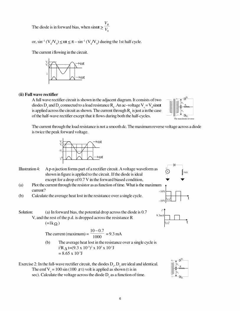
The diode is in forward bias, when sinωt > 0V
VR
or, sin–1 (Vk/V
0) < ωt < π – sin–1 (V
k/V
0) dueing the 1st half cycle.
The current i flowing in the circuit.
(ii) Full wave rectifier
A full wave rectifier circuit is shown in the adjacent diagram. It consists of two
diodes D1 and D
2 connected to a load resistance R
L. An ac–voltage V
s = V
0sinωt
is applied across the circuit as shown. The current through RL is just a in the case
of the half-wave rectifier except that it flows during both the half-cycles.
The current through the load resistance is not a smooth dc. The maximum reverse voltage across a diode
is twice the peak forward voltage.
Illustration 4: A p-n juction forms part of a rectifier circuit. A voltage waveform as
shown in figure is applied to the circuit. If the diode is ideal
except for a drop of 0.7 V in the forward biased condition,
(a) Plot the current through the resistor as as function of time. What is the maximum
current?
(b) Calculate the average heat lost in the resistance over a single cycle.
Solution: (a) In forward bias, the potential drop across the diode is 0.7
V, and the rest of the p.d. is dropped across the resistance R
(=1kΩ )
The current (maximum) = 1000
7.010 − = 9.3 mA
(b) The average heat lost in the resistance over a single cycle is
i2R ∆ t=(9.3 x 10⁻³)2 x 103 x 10-1J
= 8.65 x 10⁻³J
Exercise 2: In the full-wave rectifier circuit, the diodes D1, D
2 are ideal and identical.
The emf Vs = 100 sin (100 π t) volt is applied as shown (t is in
sec). Calculate the voltage across the diode D1 as a function of time.
6
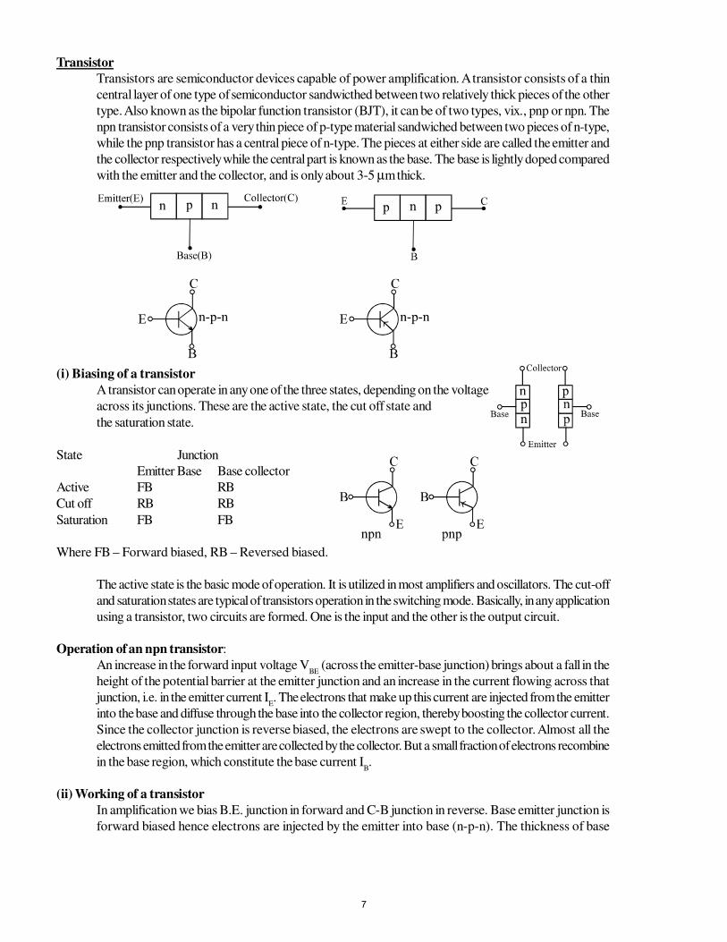
Transistor
Transistors are semiconductor devices capable of power amplification. A transistor consists of a thin
central layer of one type of semiconductor sandwicthed between two relatively thick pieces of the other
type. Also known as the bipolar function transistor (BJT), it can be of two types, vix., pnp or npn. The
npn transistor consists of a very thin piece of p-type material sandwiched between two pieces of n-type,
while the pnp transistor has a central piece of n-type. The pieces at either side are called the emitter and
the collector respectively while the central part is known as the base. The base is lightly doped compared
with the emitter and the collector, and is only about 3-5 µm thick.
(i) Biasing of a transistor
A transistor can operate in any one of the three states, depending on the voltage
across its junctions. These are the active state, the cut off state and
the saturation state.
State Junction
Emitter Base Base collector
Active FB RB
Cut off RB RB
Saturation FB FB
Where FB – Forward biased, RB – Reversed biased.
The active state is the basic mode of operation. It is utilized in most amplifiers and oscillators. The cut-off
and saturation states are typical of transistors operation in the switching mode. Basically, in any application
using a transistor, two circuits are formed. One is the input and the other is the output circuit.
Operation of an npn transistor:
An increase in the forward input voltage VBE
(across the emitter-base junction) brings about a fall in the
height of the potential barrier at the emitter junction and an increase in the current flowing across that
junction, i.e. in the emitter current IE. The electrons that make up this current are injected from the emitter
into the base and diffuse through the base into the collector region, thereby boosting the collector current.
Since the collector junction is reverse biased, the electrons are swept to the collector. Almost all the
electrons emitted from the emitter are collected by the collector. But a small fraction of electrons recombine
in the base region, which constitute the base current IB.
(ii) Working of a transistor
In amplification we bias B.E. junction in forward and C-B junction in reverse. Base emitter junction is
forward biased hence electrons are injected by the emitter into base (n-p-n). The thickness of base
7
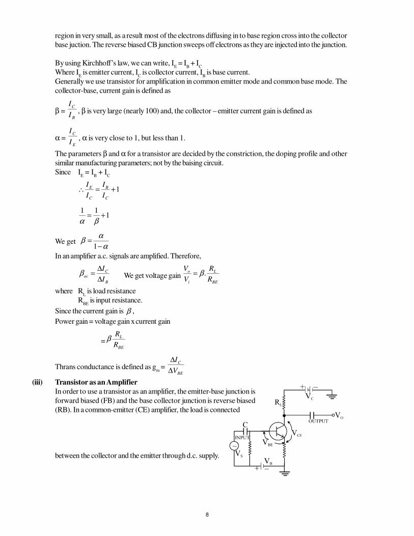
region in very small, as a result most of the electrons diffusing in to base region cross into the collector
base juction. The reverse biased CB junction sweeps off electrons as they are injected into the junction.
By using Kirchhoff’s law, we can write, IE = I
B + I
C
Where IE is emitter current, I
C is collector current, I
B is base current.
Generally we use transistor for amplification in common emitter mode and common base mode. The
collector-base, current gain is defined as
β = B
C
I
I, β is very large (nearly 100) and, the collector – emitter current gain is defined as
α = E
C
I
I, α is very close to 1, but less than 1.
The parameters β and α for a transistor are decided by the constriction, the doping profile and other
similar manufacturing parameters; not by the baising circuit.
Since IE = I
B + I
C
1+=∴C
B
C
E
I
I
I
I
111
+=βα
We get α
αβ
−=
1
In an amplifier a.c. signals are amplified. Therefore,
B
Cac
I
I
∆∆
=β We get voltage gainBE
L
i
o
R
R
V
V.β=
where RL is load resistance
RBE
is input resistance.
Since the current gain is β ,
Power gain = voltage gain x current gain
=BE
L
R
Rβ
Thrans conductance is defined as gm =
BE
C
V
I
∆∆
(iii) Transistor as an Amplifier
In order to use a transistor as an amplifier, the emitter-base junction is
forward biased (FB) and the base collector junction is reverse biased
(RB). In a common-emitter (CE) amplifier, the load is connected
between the collector and the emitter through d.c. supply.
8

An a.c. input singnal VS is superimposed on the bias V
BE. This changes V
BE by an amount
BEV∆ =Vs.
The output is taken between the collector and the gournd.
Applying Kirchoff’s voltage law on the output loop, if VS= 0.
VC = V
CE + I
CR
L
Similarly, VB = V
BE
when 0≠SV , then VB + V
S = V
BE +
BEV∆The change in V
BE can be related to the input resistance r
i and the change in I
B.
BiBES IrVV ∆=∆=
The change in IB causes a change in I
C. Thus,
B
Cac
I
I
∆∆
=β (current gain factor)
The change in IC due to a change in I
B causes a change in V
CE and the voltage drop across the resistor R
L
because VC is fixed.
Thus, ∆ VC = ∆ V
CE + R
L ∆ IC=0
vo = ∆ V
CE = -R
L ∆ IC = - β
acR
L ∆ IB
The voltage gain
Lm
i
Lac
BE
CE
i
oV Rg
r
R
V
V
v
vA −=−=
∆∆
==β
Where gm =
i
ac
r
β = transconductance.
Illustration 5: In the following circuit the base current IB is 10 µ A and the collector
current is 5.2mA. Can this transistor circuit be used
as an amplifier? In the circuit RB = 5 Ω and R
L = 1 KΩ
Solution: We know that for a transistor is CE configuration to be used as an amplifier the BE
junction must be forward biased & base collector junction must be reverse biased.
In the given question we are required to just check this
loop-1
IBR
B - I
CR
L - V
CB = 0
⇒VCB
= [(5 x 103 x 10 x 10-6) - (5.2 x 10-3 x 103)]V
⇒ (0.05 - 5.2)V
⇒vC < v
B......(1)
loop - 2
VCE
+ ICR
L - V
C = 0
⇒ VCE
= (5.5 - 5.2)V = 0.3 V ⇒ VC > V
E
as emitter is grounded, VC = 0.3V .......(2)
from (1) and (2) VB = 5.5 V ⇒ BC junction is forward biased & hence the given is
transistor would not word as an amplifier
Exercise 3: In the transistor circuit shown in figure direct current gain of the
transistor is 80. Assuming VBE ≈0, calculate (a) Base current
IB (b) Potential difference between collectors and emitter terminals.
9
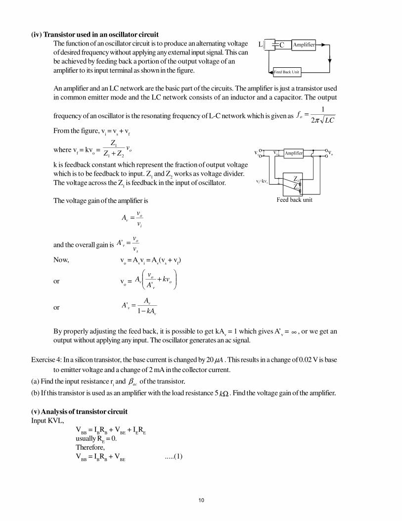
(iv) Transistor used in an oscillator circuit
The function of an oscillator circuit is to produce an alternating voltage
of desired frequency without applying any external input signal. This can
be achieved by feeding back a portion of the output voltage of an
amplifier to its input terminal as shown in the figure.
An amplifier and an LC network are the basic part of the circuits. The amplifier is just a transistor used
in common emitter mode and the LC network consists of an inductor and a capacitor. The output
frequency of an oscillator is the resonating frequency of L-C network which is given as LC
fo π2
1=
From the figure, vi = v
s + v
f
where vf = kv
o = ov
ZZ
Z
21
1
+
k is feedback constant which represent the fraction of output voltage
which is to be feedback to input. Z1 and Z
2 works as voltage divider.
The voltage across the Z1 is feedback in the input of oscillator.
The voltage gain of the amplifier is
i
ov
v
vA =
and the overall gain is s
ov
v
vA ='
Now, vo = A
vv
i = A
v(v
s + v
f)
or vo =
+ o
v
ov kv
A
vA
'
orv
vv
kA
AA
−=
1'
By properly adjusting the feed back, it is possible to get kAv = 1 which gives A’
v = ∞ , or we get an
output without applying any input. The oscillator generates an ac signal.
Exercise 4: In a silicon transistor, the base current is changed by 20 Aµ . This results in a change of 0.02 V is base
to emitter voltage and a change of 2 mA in the collector current.
(a) Find the input resistance ri and acβ of the transistor..
(b) If this transistor is used as an amplifier with the load resistance 5 Ωk . Find the voltage gain of the amplifier..
(v) Analysis of transistor circuit
Input KVL,
VBB
= IBR
B + V
BE + I
ER
E
usually RE = 0.
Therefore,
VBB
= IBR
B + V
BE.....(1)
10
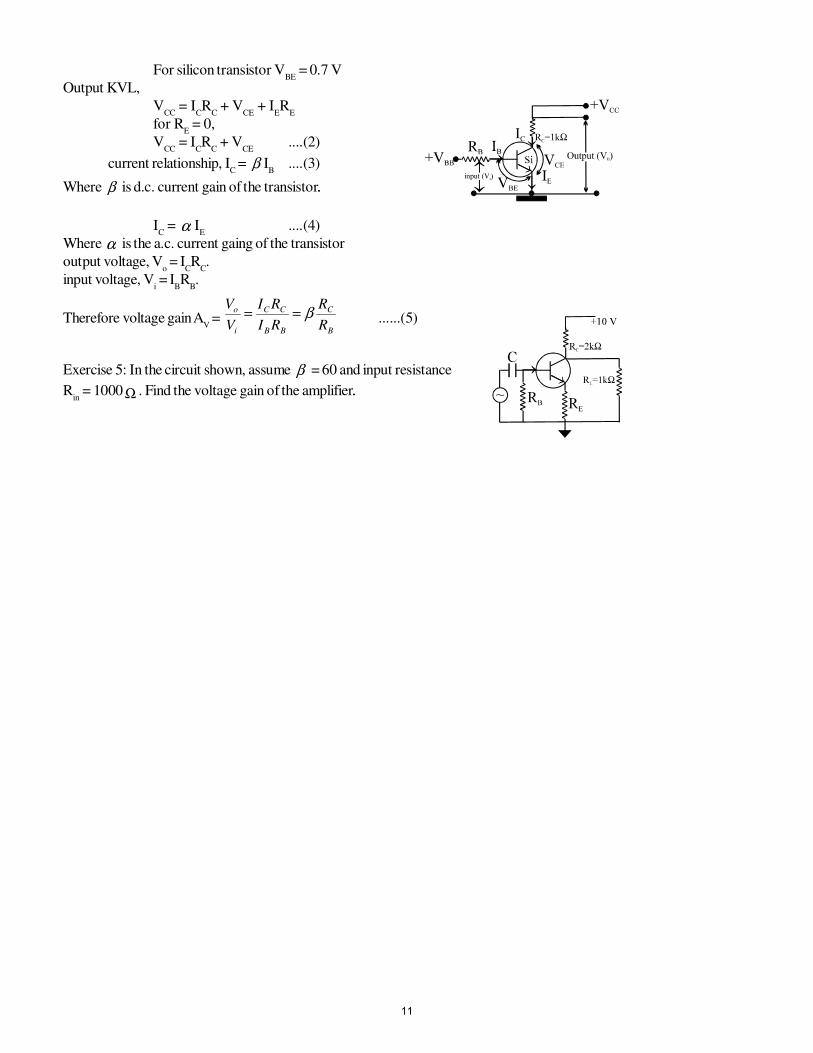
For silicon transistor VBE
= 0.7 V
Output KVL,
VCC
= ICR
C + V
CE + I
ER
E
for RE = 0,
VCC
= ICR
C + V
CE....(2)
current relationship, IC = β I
B....(3)
Where β is d.c. current gain of the transistor..
IC = α I
E....(4)
Where α is the a.c. current gaing of the transistor
output voltage, Vo = I
CR
C.
input voltage, Vi = I
BR
B.
Therefore voltage gain AV =
B
C
BB
CC
i
o
R
R
RI
RI
V
Vβ== ......(5)
Exercise 5: In the circuit shown, assume β = 60 and input resistance
Rin = 1000 Ω . Find the voltage gain of the amplifier..
11