Embed Size (px)
Citation preview

I n s t a l l a t i o nan d
M ai n t e n an c eM an u a l
with S afety Information
and Parts ListRECOMMENDED SPARE PARTS HIGHLIGHTED IN GRAY
IMPORTANT!DO NOT DESTROY
Model TL
HYTROL CONVEYOR CO., INC.© COPYRIGHT 2006–HYTROL CONVEYOR CO., INC.
Jonesboro, Arkansas
Effective October 2006(Supercedes February 2003)
Bulletin # 578
¡IMPORTANTE!NO DESTRUIR
M a n u a lde Instalación
yM a n t e n i m i e n t ocon Información sobre Seguridad
y Lista de Pa rt e sLAS PARTES DE REPUESTO RECOMENDADAS SE RESALTAN EN GRIS

2
● Table of Contents ● Indice
Warning Signs . . . . . . . . . . . . . . . . . . . . . . . . .3
INTRODUCTIONReceiving and Uncrating . . . . . . . . . . . . . . . . .4
INSTALLATIONInstallation Safety Precautions . . . . . . . . . . . .5Support Installation . . . . . . . . . . . . . . . . . . . .6Ceiling Hanger Installation . . . . . . . . . . . . . . .7Conveyor Set-Up . . . . . . . . . . . . . . . . . . . . . .8Belt Installation . . . . . . . . . . . . . . . . . . . . . . .10Electrical Equipment . . . . . . . . . . . . . . . . . . .12
OPERATIONOperation Safety Precautions . . . . . . . . . . .14Conveyor Start-Up . . . . . . . . . . . . . . . . . . . .15
MAINTENANCEMaintenance Safety Precautions . . . . . . . . . .16Lubrication . . . . . . . . . . . . . . . . . . . . . . . . . .17Belt Tracking . . . . . . . . . . . . . . . . . . . . . . . . .18Drive Chain Alignment and Tension . . . . . . .21Trouble Shooting . . . . . . . . . . . . . . . . . . . . .22Maintenance Checklist . . . . . . . . . . . . . . . . .24How To Order Replacement Parts . . . . . . .24
REPLACEMENT PARTSModel TL Parts Drawing & List8” End Drive . . . . . . . . . . . . . . . . . . . . . . . . .268” Center Drive . . . . . . . . . . . . . . . . . . . . . .288” Center Drive Assembly . . . . . . . . . . . . . .30Underside Take-Up . . . . . . . . . . . . . . . . . . . .31Standard End Power Feeder . . . . . . . . . . . .32System End Power Feeder . . . . . . . . . . . . . .34
Señales de Advertencia . . . . . . . . . . . . . . . . . . .3
INTRODUCCIONRecepción y Desembalaje . . . . . . . . . . . . . . . . .4
INSTALACIONMedidas de Seguridad al Instalar . . . . . . . . . . .5Instalación de los Soportes . . . . . . . . . . . . . . . .6Instalación de los Soportes de Techo . . . . . . . . .7Montaje . . . . . . . . . . . . . . . . . . . . . . . . . . . . . .8Instalación de la Banda . . . . . . . . . . . . . . . . . .10Equipo Eléctrico . . . . . . . . . . . . . . . . . . . . . . .12
OPERACIONMedidas de Seguridad . . . . . . . . . . . . . . . . . .14Arranque del Transportador . . . . . . . . . . . . . . .15
MANTENIMIENTOMedidas de Seguridad . . . . . . . . . . . . . . . . . .16Lubricación . . . . . . . . . . . . . . . . . . . . . . . . . . .17Alineación de la Banda . . . . . . . . . . . . . . . . . .18Alineación y Tensión de la Cadena . . . . . . . . . .21Resolviendo Problemas . . . . . . . . . . . . . . . . . .23Plan de Mantenimiento . . . . . . . . . . . . . . . . . .25Como Ordenar Refacciones . . . . . . . . . . . . . . .25
PARTES DE REPUESTODibujo y Lista de Partes del Modelo TL8” Motor de Extremo . . . . . . . . . . . . . . . . . . .268” Motor Central . . . . . . . . . . . . . . . . . . . . . .28Ensamble de la Unidad Central de 8” . . . . . . .30Ensamble del Tensor Inferior . . . . . . . . . . . . . .31Alimentador Motriz Estándar . . . . . . . . . . . . .32Alimentador Motriz de Sistema . . . . . . . . . . . .34

In an effort to reduce the possibility of injury to personnelworking around HYTROL conveying equipment, warning signs areplaced at various points on the equipment to alert them ofpotential dangers. Please check equipment and note all warningsigns. Make certain your personnel are alerted to and obey thesewarnings. Shown below are typical signs that are attached to thisequipment.
En un esfuerzo por reducir la posibilidad de accidentes del personaltrabajando junto al equipo de transportadores HYTROL, se colocanseñales de advertencia en diferentes partes del equipo para alertarlosde riesgos potenciales. Por favor verifique el equipo y asegúrese de vertodas las señales de advertencia. Asegúrese de que su personal estéalerta y obedezca las señales. Abajo se muestran las señales que seencuentran en este equipo.
● Warning Signs ● Señales de Advertencia
3
PLACED ON ALL POWERED CONVEYORSNEAR DRIVE AND/OR CONTROLS.
PLACED NEXT TO DRIVE, BOTH SIDES. PLACED ON 20 FT. INTERVALS,BOTH SIDES.
PLACED AT DRIVE OF ALL POWERED CONVEYORS.
PLACED ON TERMINATING ENDS.
COLOCADA EN TODOS LOSTRANSPORTADORES MOTORIZADOS CERCA AL
MOTOR Y/O LOS CONTROLES
COLOCADA EN LA UNIDAD MOTRIZ DE TODOS LOSTRANSPORTADORES MOTORIZADOS.
COLOCADA EN INTERVALOS DE 20 PIES, A AMBOS LADOS.
COLOCADA EN LOS EXTREMOS.
COLOCADA JUNTO A LA UNIDAD MOTRIZ, EN AMBOSLADOS.
PLACED ON ALL CHAIN GUARDS.
COLOCADA EN TODAS LAS GUARDA CADENAS.
NOTE: BILINGUAL (SPANISH) LABELS AVAILABLE UPON REQUEST.NOTA: ETIQUETAS BILINGÜES (ESPAÑOL) SERÁN PROVEÍDAS
BAJO PETICIÓN.

4
This manual provides guidelines and procedures for installing,operating, and maintaining your conveyor. A complete parts list isprovided with recommended spare parts highlighted in gray.Important safety information is also provided throughout themanual. For safety to personnel and for proper operation of yourconveyor, it is recommended that you read and follow theinstructions provided in this manual.
Check the number of items received against thebill of lading.Examine condition of equipment to determine ifany damage occurred during shipment.Move all crates to area of installation.Remove crating and check for optional equipmentthat may be fastened to the conveyor. Make surethese parts (or any foreign pieces) are removed.
Este manual provee las pautas y los procedimientos para instalar,operar, y mantener su transportador. Se proporciona una lista completade re facciones con las recomendadas resaltadas en gri s. S eproporciona también información importante para prevención deaccidentes en cada una de las partes de este manual. Para seguridaddel personal y para un funcionamiento apropiado del transportador, serecomienda que se lean y se sigan cada una de las instrucciones.
1. . .
2. . .
3. . .4. . .
Compare el número de partes recibidas con las delconocimiento del embarque.Examine las condiciones del equipo para determinar sialgún daño ha ocurrido durante el transporte.Translade el equipo al área de instalación.Desempaque y verifique si hay partes opcionalesatadas al equipo. Asegúrese de que estas partes (ocualquier otras partes ajenas al equipo) seanremovidas.
1. . .
2. . .
3. . .4. . .
NOTE: If damage has occurred or freight is missing,see the “Important Notice” attached to the crate.
NOTA: Si algún daño ha ocurrido o faltan partes, vealas "Notas Importantes" adheridas al embalaje.
I N T R O D U C T I ON I N T R O D U CC I O N
● Receiving andUncrating
● Recepción yDesembalaje

5
GUARDS AND GUARDINGInterfacing of Equipment. When two or morepieces of equipment are interfaced, special attentionshall be given to the interfaced area to insure thepresence of adequate guarding and safety devices.Guarding Exceptions. Wherever conditions prevailthat would require guarding under these standards, butsuch guarding would render the conveyor unusable,prominent warning means shall be provided in the areaor on the equipment in lieu of guarding.G u arded by Location or Position. W h e renecessary for the protection of employees from hazards,all exposed moving machinery parts that present ahazard to employees at their work station shall bemechanically or electrically guarded, or guarded bylocation or position.
When a conveyor passes over a walkway, roadway, orwork station, it is considered guarded solely by locationor position if all moving parts are at least 8 ft. (2.44 m)above the floor or walking surface or are otherwiselocated so that the employee cannot inadvertently comein contact with hazardous moving parts.
Although overhead conveyors may be guarded bylocation, spill guard, pan guards, or equivalent shall beprovided if the product may fall off the conveyor for anyreason and if personnel would be endangered.
HEADROOMWhen conveyors are installed above exit passageways,aisles, or corridors, there shall be provided a minimumclearance of 6 ft. 8 in. (2.032 m) measured vertically fromthe floor or walking surface to the lowest part of theconveyor or guards.
Where system function will be impaired by providingthe minimum clearance of 6 ft. 8 in. (2.032 m) through anemergency exit, alternate passageways shall be provided.It is permissible to allow passage under conveyors withless than 6 ft. 8 in. (2.032 m) clearance from the floor forother than emergency exits if a suitable warningindicates low headroom.
GUARDAS Y PROTECCIONES Ensamble del Equipo. Cuando dos o más piezas delequipo van unidas, debe ponerse especial atención al área deunión para asegurar que las guardas adecuadas y losdispositivos de seguridad, estén presentes.Excepciones de Protección. Dondequiera que lasguardas sean necesarias, pero que la colocación de lasmismas inhabilite el uso del transportador, se omitirán lasguardas y se proporcionarán señales visibles de advertenciaya sea en el área o en el equipo.P rotección dada por Posición o Ubicación.Cuando sea necesaria la protección de los empleados contraposibles riesgos, todas las partes del equipo que esténexpuestas y en movimiento, y que puedan presentar peligro,serán protegidas mecánica o eléctricamente, o protegidas porsu posición o ubicación.
Cuando el transportador está instalado sobre pasillos,corredores o puestos de trabajo, se considera protegidoúnicamente por localización o posición si todas las partes enmovimiento están situadas a mínimo a 8 pies (2.44m) dealtura del piso, o si está localizadas de tal manera que elempleado no pueda entrar en contacto inadvertidamentecon dichas partes.
A pesar de que los transportadores áereos pueden estarprotegidos por su localización, guardas laterales e inferioresdeben ser proporcionadas para evitar que el producto caigafuera del transportador y así mantener al personal fuera depeligro.
UBICACION SUPERIORCuando los transportadores son instalados sobre pasillos ocorredores de salida, debe dejarse un espacio libre demínimo 6 pies 8 pulgadas (2,032m) de altura, midiendoverticalmente desde el piso o área de tránsito hasta la partemás baja del transportador o de las guardas.
Si se proporcionan señales de advertencia adequadasindicando baja altura; es posible dejar espacio libre conmenos de 6 pies 8 pulgadas (2.032m) de extensión entre elpiso y el transportador en los pasillos que no sean salidas deemergencia.
INSTALLATION INSTALACION
● Installation SafetyPrecautions for Conveyorsand Related Equipment
● Medidas de Seguridadal Instalar Transportadoresy Equipos Relacionados

6
● Support Installation ● Instalación de los Soport e s
Determine primary direction of product flow.Figure 6A indicates the preferred flow as relatedto the drive.R e fer to “Match-Mark” numbers on ends ofconveyor sections. (Figure 6A).Attach supports to both ends of drive section andto one end of intermediate or tail sections (Figure6A). Hand tighten bolts only at this time.Adjust elevation to required height.
1. . .
2. . .
3. . .
4. . .
Determine la dirección primaria del flujo del producto.La figura 6A indica el flujo preferido en relación con launidad motriz.Refiérase a las “Etiquetas de Secuencia de Armado”situadas al final de las secciones del transportador.(Figura 6A).Fije los soportes en ambos extremos de la secciónmotriz y a un extremo de la sección intermedia o final(Figura 6A).Apriete los tornillos manualmente.Ajuste la elevación a la altura requerida.
1. . .
2. . .
3. . .
4. . .
DRIVE SECTIONINTERMEDIATE OR TAIL SECTION
ADJUST TO DESIREDELEVATION
(FLUJO DEL PRODUCTO)
(SECCION FINAL O INTERMEDIA) (SECCION MOTRIZ)
(AJUSTE A LA ELEVACIONDESEADA)
( N OTA :AL A J U S TAR LOS SOPORTES DEJE ESPACIO SEGUN ELESPESOR DE LA BA N D A . )
(ETIQUETAS DE SECUENCIA DE ARMADO)4”
2”2”
“MATCH-MARK” NUMBERS
TAIL SECTION
NOTE: ALLOW FOR BELT THICKNESSWHEN ADJUSTING SUPPORTS
SPLICE PLATE
PRODUCT FLOW FLOW
(PLACA DE UNION)
(SECCION DE RETORNO)
FIGURE 6A

7
● Ceiling HangerInstallation
● Instalación de losSoportes a Techo
If conveyors are to be used in an overhead application,ceiling hangers may have been supplied in place of floorsupports.Figure 7A shows how a ceiling hanger mounts to aconveyor section. Ceiling hangers should be mountedat section joints. For safety information concerningconveyors mounted overhead, refer to “InstallationSafety Precautions” on Page 5.
NOTE: When installing ceiling hanger rods in anexisting building, all methods of attachment mustcomply with local building codes.
FIGURE 7A
Si los transportadores van a ser usados en aplicacionesaéreas o superiores, soportes colgantes del techo pudieronhaber sido suministrados en vez de los soportes de piso.La figura 7A muestra como un soporte colgante de techose instala en un transportador. Los soportes colgantesdeben montarse en la unión de las secciones. Parainformación de seguridad respecto al montaje detransportadores aéreos, refiérase a “Medidas de Seguridadal Instalar” en la página 5.
NOTA: Cuando se instalan varillas colgantes al techo enuna construcción existente, todos los métodos de unióndeben cumplir con los códigos locales de construcción.
(CANAL LATERAL)
(ABRAZADERA)
(TORNILLO CANDADO)
(CONTRA TUERCA)
(TUBO DE SOPORTE)
(CONTRA TUERCA)
(ESPACIADOR)SPACER
SIDE CHANNEL
JAM NUT
SUPPORT PIPE
JAM NUT
LOCK BOLT
PIPE RETAINER
(TORNILLO DE MONTAJE)MOUNTING BOLTS
(VARILLA COLGANTEAL TECHO)
CEILING HANGER ROD

8
● Conveyor Set-Up ● Instalación
Mark a chalk line on floor to locate center of theconveyor (Floor Mounted Conveyors).Place the drive section in position.Install remaining sections placing end withoutsupport on extend support of previous section(Figure 9A). Check “Match Mark” Numbers to seethat adjoining sections are in proper sequenceFasten sections together with splice plates andpivot plates (Figure 9B). Hand tighten bolts only.Check to see that conveyor is level across widthand length of unit.Adjust supports as necessary.Tighten all splice plates and support mountingbolts and lag conveyor to the floor.Install electrical controls and wire motor. See Page12.Install and track belt per instructions on Pages 10and 18.
1. . .
2. . .3. . .
4. . .
5. . .
6. . .
7. . .
8. . .
Marque con tiza una línea en el suelo para ubicar el centro deltransportador. (Transportadores Montados en el Piso).Coloque la sección motriz en posición.Instale las secciones restantes, colocando el extremosin soporte en la placa pivote de la sección anterior(Fig. 9A). Revise las etiquetas de Secuencia de Armadopara asegurarse que las secciones unidas estén en elorden correcto.Sujete las secciones con placas de unión y placaspivote (Fig. 9B). Apriete los tornillos manualmente.Revise si el transportador está nivelado a lo ancho ylargo de la unidad. Ajuste los soportes como seanecesario.Apriete todas las placas de union y los tornillos demontaje, y ancle el transportador al piso.Instale los controles eléctricos y conecte el motor.Veala Página 12.Instale y alinie la banda con las instrucciones de lasPáginas 10 y 18.
1. . .
2. . .3. . .
4. . .
5. . .
6. . .
7. . .
8. . .

9
STATIONARY SUPPORT
PIVOT PLATE
SPLICE PLATE
BED SECTION
MOUNTING BOLT
INTERMEDIATE SECTION
“ M ATCH-MARK” NUMBERS
DRIVE SECTION(SECCION DE LA
UNIDAD MOTRIZ)
(SECCION INTERMEDIA)
(ETIQUETAS DE ARMADO)
(CAMA)
(TORNILLO DE MONTAJE)
(PLACA DE UNION)
(PLACA PIVOTE)
(SOPORTE ESTACIONARIO)
FIGURE 9A
FIGURE 9B
BED SECTION(CAMA)

10
● Belt Installation ● Instalación de la Banda
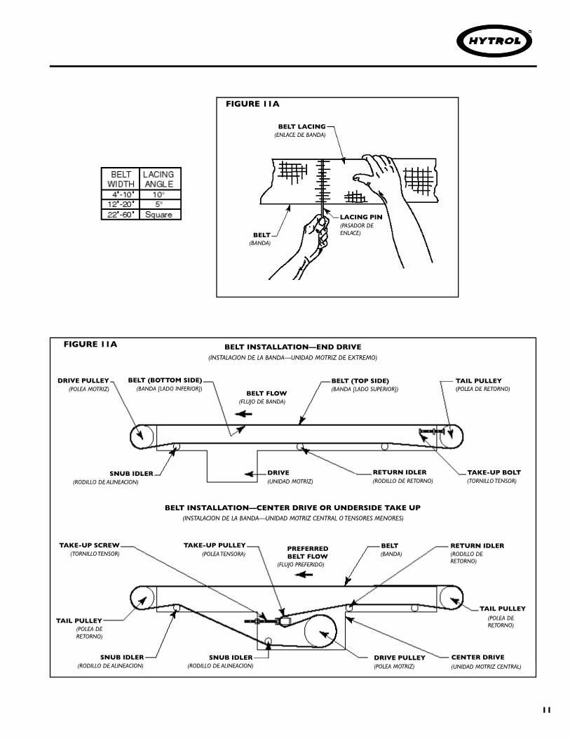
The conveyor belt has been pre-cut to the properlength, and lacing installed at the factory.To install followthese steps:
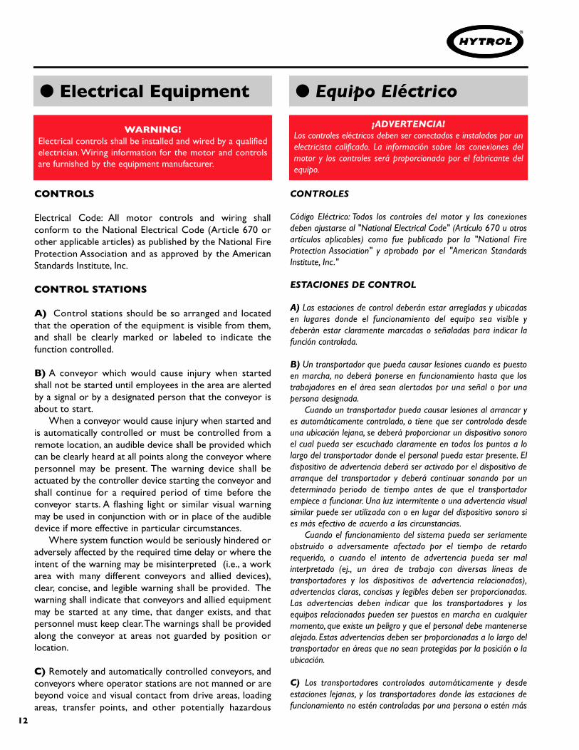
Thread belt through conveyor as shown in Figure11B.Pull ends together and insert lacing pin (Figure11A).Adjust belt tension with take-up pulley. Keeppulley square by moving both take-up bolts anequal amount. Maintain enough tension so drivepulley will not slip when carrying the rated load.Track belt per instructions on Page18.
La banda del transportador ha sido previamente cortada yenlazada en la fábrica. Para instalarla siga los siguientespasos:
1. . .
2. . .
3. . .
4. . .
Coloque la banda a través del transportador (Figura11B).Junte los extremos e incerte el pasador de enlace(Figura 11A).Ajuste la tensión de la banda con las poleas tensoras.Mantenga la polea encuadrada moviendo los tornillostensores a la misma distancia. Mantenga suficientetension para que la polea motriz no se resvale cuandotransporte la carga estimada.Alinie la banda de acuerdo a las instrucciones de lapágina 18.
1. . .
2. . .
3. . .
4. . .
N OTE: If belt ends cannot be pulledtogether by hand, it may be necessary toloosen take-ups (at tail pulley, etc. ) ,minimum position or use a belt puller solacing pin can be easily inserted.
NOTA: Si los extremos de la banda no puedenser unidos manualmente, afloje los tornillostensores (en la polea de retorno, etc.) ó puedeusar un jalador de banda hasta que elpasador pueda ser facilmenteinsertado.XXXX
CAUTION!Excessive slippage will reduce belt life and damagedrive pulley lagging. Never apply more tension than isneeded. Over-tension will cause extra wear to belt andbearings and will require extra power from drive.
¡ P R E C AU C I O N !El patinaje excesivo reducirá la vida de la banda y dañará elrevestimiento de la polea motri z . Nunca aplique mas tensiónde la necesari a . Una sobre-tensión causará un desgaste extrade la banda y los ro d a m i e n t o s, y re q u e rirá una mayor potenciade la unidad motri z .
11
SNUB IDLER
SNUB IDLER
TAKE-UP SCREW
BELT (BOTTOM SIDE)
TAKE-UP PULLEY
BELT (TOP SIDE)
BELT FLOW
BELT INSTALLATION—END DRIVE
BELT INSTALLATION—CENTER DRIVE OR UNDERSIDE TAKE UP
BELT RETURN IDLER
TAIL PULLEY
TAIL PULLEY
TAKE-UP BOLTRETURN IDLERDRIVE
CENTER DRIVEDRIVE PULLEY
(POLEA DE RETORNO)(BANDA [LADO SUPERIOR])
(FLUJO DE BANDA)
(BANDA [LADO INFERIOR])
(TORNILLO TENSOR)(RODILLO DE RETORNO)(UNIDAD MOTRIZ)(RODILLO DE ALINEACION)
(POLEA DERETORNO)
(RODILLO DERETORNO)
(BANDA)(POLEA TENSORA)(TORNILLO TENSOR)
(RODILLO DE ALINEACION) (POLEA MOTRIZ) (UNIDAD MOTRIZ CENTRAL)
(FLUJO PREFERIDO)
(INSTALACION DE LA BANDA—UNIDAD MOTRIZ DE EXTREMO)
(INSTALACION DE LA BANDA—UNIDAD MOTRIZ CENTRAL O TENSORES MENORES)
SNUB IDLER(RODILLO DE ALINEACION)
PREFERREDBELT FLOW
DRIVE PULLEY(POLEA MOTRIZ)
LACING PIN(PASADOR DEENLACE)
BELT LACING(ENLACE DE BANDA)
BELT(BANDA)
TAIL PULLEY(POLEA DERETORNO)
FIGURE 11A
FIGURE 11A
12
● Electrical Equipment ● Equipo Eléctrico
CONTROLS
Electrical Code: All motor controls and wiring shallconform to the National Electrical Code (Article 670 orother applicable articles) as published by the National FireProtection Association and as approved by the AmericanStandards Institute, Inc.
CONTROL STATIONS
A) Control stations should be so arranged and locatedthat the operation of the equipment is visible from them,and shall be clearly marked or labeled to indicate thefunction controlled.
B) A conveyor which would cause injury when startedshall not be started until employees in the area are alertedby a signal or by a designated person that the conveyor isabout to start.
When a conveyor would cause injury when started andis automatically controlled or must be controlled from aremote location, an audible device shall be provided whichcan be clearly heard at all points along the conveyor wherepersonnel may be present. The warning device shall beactuated by the controller device starting the conveyor andshall continue for a required period of time before theconveyor starts. A flashing light or similar visual warningmay be used in conjunction with or in place of the audibledevice if more effective in particular circumstances.
Where system function would be seriously hindered oradversely affected by the required time delay or where theintent of the warning may be misinterpreted (i.e., a workarea with many different conveyors and allied devices),clear, concise, and legible warning shall be provided. Thewarning shall indicate that conveyors and allied equipmentmay be started at any time, that danger exists, and thatpersonnel must keep clear.The warnings shall be providedalong the conveyor at areas not guarded by position orlocation.
C) Remotely and automatically controlled conveyors, andconveyors where operator stations are not manned or arebeyond voice and visual contact from drive areas, loadingareas, transfer points, and other potentially hazardous
CONTROLES
Código Eléctrico: Todos los controles del motor y las conexionesdeben ajustarse al "National Electrical Code" (Artículo 670 u otrosartículos aplicables) como fue publicado por la "National FireProtection Association" y aprobado por el "American StandardsInstitute, Inc."
ESTACIONES DE CONTROL
A) Las estaciones de control deberán estar arregladas y ubicadasen lugares donde el funcionamiento del equipo sea visible ydeberán estar claramente marcadas o señaladas para indicar lafunción controlada.
B) Un transportador que pueda causar lesiones cuando es puestoen marcha, no deberá ponerse en funcionamiento hasta que lostrabajadores en el área sean alertados por una señal o por unapersona designada.
Cuando un transportador pueda causar lesiones al arrancar yes automáticamente controlado, o tiene que ser controlado desdeuna ubicación lejana, se deberá proporcionar un dispositivo sonoroel cual pueda ser escuchado claramente en todos los puntos a lolargo del transportador donde el personal pueda estar presente. Eldispositivo de advertencia deberá ser activado por el dispositivo dearranque del transportador y deberá continuar sonando por undeterminado periodo de tiempo antes de que el transportadorempiece a funcionar. Una luz intermitente o una advertencia visualsimilar puede ser utilizada con o en lugar del dispositivo sonoro sies más efectivo de acuerdo a las circunstancias.
Cuando el funcionamiento del sistema pueda ser seriamenteobstruido o adversamente afectado por el tiempo de retardorequerido, o cuando el intento de advertencia pueda ser malinterpretado (ej., un área de trabajo con diversas líneas detransportadores y los dispositivos de advertencia relacionados),advertencias claras, concisas y legibles deben ser proporcionadas.Las advertencias deben indicar que los transportadores y losequipos relacionados pueden ser puestos en marcha en cualquiermomento, que existe un peligro y que el personal debe mantenersealejado. Estas advertencias deben ser proporcionadas a lo largo deltransportador en áreas que no sean protegidas por la posición o laubicación.
C) Los transportadores controlados automáticamente y desdeestaciones lejanas, y los transportadores donde las estaciones defuncionamiento no estén controladas por una persona o estén más
WARNING!Electrical controls shall be installed and wired by a qualifiedelectrician. Wiring information for the motor and controlsare furnished by the equipment manufacturer.
¡ADVERTENCIA!Los controles eléctricos deben ser conectados e instalados por unelectricista calificado. La información sobre las conexiones delmotor y los controles será proporcionada por el fabricante delequipo.

13
locations on the conveyor path not guarded by location,position, or guards, shall be furnished with emergency stopbuttons, pull cords, limit switches, or similar emergencystop devices.
All such emergency stop devices shall be easilyidentifiable in the immediate vicinity of such locationsunless guarded by location, position, or guards.Where thedesign, function, and operation of such conveyor clearly isnot hazardous to personnel, an emergency stop device isnot required.
The emergency stop device shall act directly on thecontrol of the conveyor concerned and shall not dependon the stopping of any other equipment. The emergencystop devices shall be installed so that they cannot beoverridden from other locations.
D) Inactive and unused actuators, controllers, and wiringshould be removed from control stations and panel boards,together with obsolete diagrams, indicators, control labels,and other material which serve to confuse the operator.
SAFETY DEVICES
A) All safety devices, including wiring of electrical safetydevices, shall be arranged to operate in a “Fail-Safe”manner, that is, if power failure or failure of the device itselfwould occur, a hazardous condition must not result.
B) Emergency Stops and Restarts. Conveyor controls shallbe so arranged that, in case of emergency stop, manualreset or start at the location where the emergency stopwas initiated, shall be required of the conveyor(s) andassociated equipment to resume operation.
C) Before restarting a conveyor which has been stoppedbecause of an emergency, an inspection of the conveyorshall be made and the cause of the stoppage determined.The starting device shall be locked out before any attemptis made to remove the cause of stoppage, unless operationis necessary to determine the cause or to safely removethe stoppage.
Refer to ANSI Z244.1-1982, American National Standardfor Personnel Protection – Lockout/Tagout of EnergyS o u rces – Minimum Safety Requirements and OSHAStandard Number 29 CFR 1910.147 “The Control ofHazardous Energy (Lockout/Tagout).”
allá del alcance de la voz y del contacto visual de las áreas deconducción, áreas de carga, puntos de transferencia y otros sitiospotencialmente peligrosos localizados en la tra ye c t o ria deltransportador que no tenga protección por posición, ubicación, oguardas, deberán ser equipados con interruptores de parada deemergencia, cordones de parada de emergencia, interruptores delímite o dispositivos similares para paradas de emergencia.
Todos estos dispositivos de parada de emergencia deberán serfácilmente identificables en las cercanías inmediatas a estos puntospotencialmente peligrosos, a no ser que estén protegidos dada suubicación, posición o protegidos con guardas. Donde el diseño, elf u n c i o n a m i e n t o , y la operación de tales tra n s p o rt a d o res norepresente un claro peligro para el personal, no se requieren losdispositivos de parada de emergencia.
El dispositivo de parada de emergencia debe actuardirectamente en el control del transportador concerniente y nodebe depender de la parada de cualquier otro equipo. Losdispositivos de parada de emergencia deben ser instalados de talforma que no puedan ser anulados desde otras localidades.
D) Los controles, los actuadores inactivos o no usados y los cables,deberán ser removidos de las estaciones de control y de los tablerosde mando, junto con los diagramas, indicadores, etiquetas de controly otros materiales obsoletos, los cuales pueden confundir aloperador.
DISPOSITIVOS DE SEGURIDAD
A) Todos los dispositivos de seguridad, incluyendo la conexión dedispositivos eléctricos, deben estar dispuestos para operar en unamanera de "autoprotección"; es decir, si se presenta una pérdida decorriente o un fallo en el mismo dispositivo, esto no deberepresentar peligro.
B) Paradas de Emergencia y Reactivadores. Los controles deltransportador deberán estar dispuestos de tal manera que en casode una parada de emergencia, se requiera un activador oarrancador manual en la ubicación donde la parada de emergenciase presenta para poder reanudar la operación del transportador otransportadores y equipo asociado.
C) Antes de volver a poner en marcha un transportador que hayasido detenido por una emergencia, debe revisarse y determinar lacausa de la parada. El dispositivo de arranque deberá serbloqueado antes de intentar corregir o remover la causa queoriginó la parada, a no ser que la operación del transportador seanecesaria para determinar la causa o para solucionar el problema.
Refiérase a ANSI Z244.1-1982, "American National Standard forPe rsonnel Protection" - Locko u t / Ta gout of Energy Sources -Minimum Safety Requirements and OSHA Standard Number 29CFR 1910.147 "The Control of Hazardous Energy(Lockout/Tagout)."
14
OPERATION OPERACION
● Operation SafetyPrecautions
● Medidas de Seguridaden la Operación
A) Only trained employees shall be permitted tooperate conveyors. Training shall include instruction inoperation under normal conditions and emergencysituations.
B) Where employee safety is dependent upon stoppingand/or starting devices, they shall be kept free ofobstructions to permit ready access.
C)The area around loading and unloading points shall bekept clear of obstructions which could endangerpersonnel.
D) No person shall ride the load-carrying element of aconveyor under any circumstances unless that person isspecifically authorized by the owner or employer to doso. Under those circumstances, such employee shall onlyride a conveyor which incorporates within its supportings t r u c t u re, p l a t forms or control stations specificallydesigned for carrying personnel. Under nocircumstances shall any person ride on any element of avertical conveyor. Owners of conveyors should affixwarning devices to the conveyor reading Do Not RideConveyor.
E) Personnel working on or near a conveyor shall beinstructed as to the location and operation of pertinentstopping devices.
F) A conveyor shall be used to transport only materialit is capable of handling safely.
G ) Under no circumstances shall the safe t ycharacteristics of the conveyor be altered if suchalterations would endanger personnel.
A) Solo se debe permitir operar los transportadores aempleados entre n a d o s. El entrenamiento debe incl u i rinstrucciones de operación bajo condiciones normales y ensituaciones de emergencia.
B) Cuando la seguridad de los trabajadores dependa dedispositivos de parada y/o arranque, tales dispositivos debenmantenerse libres de obstrucciones para permitir un accesorápido.
C) El área alrededor de los puntos de carga y descarga debemantenerse libre de obstrucciones, las cuales podrían poneren peligro al personal.
D) Ninguna persona debe subirse en la parte de conducciónde carga de un transportador bajo ninguna circunstancia almenos que esta persona sea autorizada por el dueño o porel supervisor. Bajo estas circunstancias, el empleado debes u b i rse solamente en un tra n s p o rtador que tengai n c o r p o radas dentro de su estructura , p l a t a formas oestaciones de control especialmente diseñadas para eltraslado de personal. Bajo ninguna circunstancia, personaalguna debe subirse en cualquier parte de un transportadorvertical. Los dueños de los transportadores deben añadirseñales de advertencia al transportador con el texto: "Nosubirse en el Transportador".
E ) El personal que esté trabajando en o cerca altransportador, debe ser instruído en cuanto a la ubicación yoperación de los dispositivos de parada.
F) Un transportador debe ser utilizado para transportar sololos productos que sea capaz de manejar con seguridad.
G ) Bajo ninguna circunstancia las características deseguridad de un transportador deben ser alteradas si talesalteraciones puden poner en peligro al personal.

15
● Conveyor Start-Up
Before conveyor is turned on, check for foreign objectsthat may have been left inside conveyor duringinstallation. These objects could cause serious damageduring start-up.After conveyor has been turned on and is operating,check motors, reducers, and moving parts to make surethey are working freely.
●A r ranque del Tra n s p o rtador
¡PRECAUCION!Debido a la cantidad de partes en movimiento deltransportador, todo el personal en el área del transportadornecesita ser advertido de que este está a punto deponerse en marcha.
Antes de poner en marcha el transportador, revise si hayobjetos ajenos que puedan haber sido dejados dentro deltransportador durante la instalación. Estos objetos puedencausar serios daños durante el arranque.Después de poner en marcha el transportador y que estéo p e ra n d o , revise los motore s, re d u c t o res y partes enmovimiento para estar seguro de que están trabajandolibremente.
CAUTION!Because of the many moving parts on the conveyor, allpersonnel in the area of the conveyor need to bewarned that the conveyor is about to be started.
H) Routine inspections and preventive and correctivemaintenance programs shall be conducted to insure thatall safety features and devices are retained and functionproperly.
I) Personnel should be alerted to the potential hazard ofentanglement in conveyors caused by items such as longhair, loose clothing, and jewelry.
J) As a general rule, conveyors should not be cleanedwhile in operation.Where proper cleaning requires theconveyor to be in motion and a hazard exists, personnelshould be made aware of the associated hazard.
H) Inspecciones rutinarias deben llevarse a cabo al igual queprogramas de mantenimiento preventivos y correctivos, con lafinalidad de asegurar que todos los dispositivos y medidas deseguridad sean conservados en buen estado y funcionencorrectamente.
I) El personal debe ser advertido de las posibles causas depeligros potenciales tales como enredos en transportadorespor llevar cabello largo, ropa suelta o joyas, etc.
J) Como regla general, los transportadores no deberánlimpiarse mientras estén en funcionamiento. Cuando serequiera limpiar el transportador estando en movimiento yexista posibilidad de peligro, el personal deberá ser advertidode ese posible riesgo.
16
M A I N T E NA N C E M A N T E N I M I E N TO
A ) M a i n t e n a n c e, such as lubrication and adjustments, s h a l lbe performed only by qualified and trained personnel.
B ) It is Important that a maintenance program beestablished to insure that all conveyor components aremaintained in a condition which does not constitute ah a z a rd to personnel.
C ) When a conveyor is stopped for maintenancep u r p o s e s , s t a rting devices or powe red accessories shall bel o c ked or tagged out in accordance with a fo r m a l i z e dp ro c e d u re designed to protect all person or gro u p si nvo l ved with the conveyor against an unexpected start .
D ) Replace all safety devices and guards befo re start i n gequipment for normal operation.
E ) W h e n ever practical, DO NOT lubricate conveyo r swhile they are in motion. O n ly trained personnel who areaw a re of the hazard of the conveyor in motion shall bea l l owed to lubricate.
SAFETY GUA R D SMaintain all guards and safety devices IN POSITION a n dIN SAFE REPA I R .
WARNING SIGNSMaintain all warning signs in a legible condition and obey allw a r n i n g s .See Page 3 of this manual for examples of warnings i g n s .
A ) El mantenimiento, tal como lubricación y ajustes, debe serrealizado solamente por personal calificado y entre n a d o .
B) Es importante que se establezca un programa dem a n t e n i m i e n t o , p a ra asegurar que todos los componentes deltransportador sean mantenidos en condiciones que noc o n s t i t u yan un peligro para el pers o n a l .
C ) Cuando un tra n s p o rtador esté parado por ra zones dem a n t e n i m i e n t o , los dispositivos de arranque o accesori o sm o t o rizados deben ser asegurados o desconectados siguiendo unprocedimiento diseñado para evitar cualquier arranquei n e s p e rado que pueda causar heridas a la persona o grupos dep e rsonas inv o l u c rados con el tra n s p o rt a d o r.
D ) Antes de poner en marcha el equipo, vuelva a colocar todaslas guardas y dispositivos de seguridad en su lugar.
E ) S i e m p re que sea práctico, N O l u b rique los tra n s p o rt a d o re sm i e n t ras se encuentren en mov i m i e n t o . Solo el pers o n a lentrenado, que tenga conocimiento de los peligros delt ra n s p o rtador en mov i m i e n t o , se le permitirá lubricarlos de estam a n e ra .
P R OT E CCIONES DE SEGURIDA DMantenga todas las guardas y dispositivos de seguridad EN SUP O S I C I O N y EN BU E NAS CO N D I C I O N E S.
SEÑALES DE ADV E RT E N C I AMantenga todas las señales de advertencia en condicioneslegibles y obedézcalas. Remítase a la página 3 de este manualp a ra ver ejemplos de señales de advert e n c i a .
● Maintenance SafetyPrecautions
● Medidas de Seguridaden el Mantenimiento

17
The drive chain is pre-lubricated from the manufacturerby a hot dipping process that ensures total lubrication ofall components. However, continued proper lubricationwill greatly extend the useful life of every drive chain.
D r i ve Chain lubrication serves several purposesincluding:
• Protecting against wear of the pin-bushing joint• Lubricating chain-sprocket contact surfaces• Preventing rust or corrosion
For normal operating environments, lubricate every2080 hours of operation or every 6 months, whichevercomes first. Lubricate with a good grade of non-detergent petroleum or synthetic lubricant (i.e., Mobile1 Synthetic). For best results, always use a brush togenerously lubricate the chain. The proper viscosity oflubricant greatly affects its ability to flow into theinternal areas of the chain. Refer to the table below forthe proper viscosity of lubricant for your application.
The drive chain’s lubrication requirement is greatlya f fected by the operating conditions. For harshconditions such as damp env i ro n m e n t s , d u s t ye nv i ro n m e n t s , e x c e s s i ve speeds, or elev a t e dtemperatures, it is best to lubricate more frequently. Itmay be best, under these conditions, to develop acustom lubrication schedule for your specificapplication. A custom lubrication schedule may bedeveloped by inspecting the drive chain on regular timeintervals for sufficient lubrication. Once the timei n t e rval is determined at which the chain is notsufficiently lubricated, lubricate it and schedule thefuture lubrication intervals accordingly.
La cadena motriz ha sido pre-lubricada por el fabricantemediante un proceso de sumersión caliente que asegura unalubricación total de todos sus componentes. Sin embargo, unalubricación apropiada y continua extenderá su vida útilenormemente.
La lubricación de la cadena motriz cumple varios propósitos:• Proteger contra el desgaste de la unión de pines de la
cadena • Lubricar las superficies de contacto entre la cadena y el
sprocket• Prevenir la oxidación o corrosión.
En operaciones bajo condiciones ambientales normales,lubrique cada 2080 horas de operación o cada 6 meses, loque ocurra primero. Lubrique con un lubricante sintético (ej.Mobile 1 sintético) o basado en petroleo no-detergente debuen grado. Para mejores resultados, siempre utilice unabrocha para lubricar la cadena generosamente. La viscosidadapropiada del lubricante afecta enormente el fluido delmismo hacia las áreas internas de la cadena. Refiérase a lasiguiente tabla para consultar la viscosidad de lubricanteadecuada para su aplicación.
El requerimiento de lubricación de la cadena motriz se véafectado por las condiciones de operación. En condicionesdifíciles tales como: ambientes humedos, ambientes conpolvo, velocidades excesivas, o temperaturas elevadas, serecomienda lubricar la cadena con más frecuencia. Loapropiado sería que bajo estas condiciones se establezca unprograma de lubricación específico para su aplicación. Estep rog rama podrá llev a rse a cabo inspeccionando lalubricacion suficiente de la cadena motriz en intervalosregulares de tiempo. Una vez se ha determinado el intervaloen el cual la cadena no se encuentra suficientementelubricada, lubríquela y programe los siguientes intervalos deacuerdo al intervalo anterior.
● Lubrication ● Lubricación
Ambient Temperature SAE ISODegrees F
20-40 20 46 or 6840-100 30 100100-120 40 150 Te m p e ra t u ra A m b i e n t e S A E I S O
( G rados Fº) ( G rados Cº)2 0 - 4 0 -07 – 04 2 0 46 o 684 0 - 1 0 0 04 – 38 3 0 1 0 01 0 0 - 1 2 0 38 – 49 4 0 1 5 0

18
● Belt Tracking ● Alineación de la Banda
HOW IS THE CONVEYOR BELT TRACKEDThe belt is tracking by adjusting: Drive Pulley,Tail Pulley,Return Idlers, and Snub Idlers. The same trackingprinciples apply to conveyors supplied with end drives,center drives, or underside take-ups.
PRE-TRACKING INSPECTIONBefore attempting to physically track the belt:
Make sure conveyor is level across the width andlength of unit. Adjust supports as necessary.Check to make sure: Drive Pulley,Tail Pulley, SnubIdlers, and all Return Idlers are square withconveyor bed. See illustrations 18A, 19A, 19B and19C.Dimension “A” should be equal on both sidesof unit.M a ke sure belt has been pro p e r ly thre a d e dthrough conveyor. See “Belt Installation”, Page 10.Check for improper loading. Feed should be indirection of belt travel, centered on belt.Make sure belt lacing has been installed correctlyand is square with the belt.
COMO ES LA BANDA ALINEADALa banda se alinea al ajustar: La Polea Motriz, Polea deRetorno, Rodillos de Retorno, y Rodillos de Ajuste. Los mismospricipios de ajuste se aplican a los transportadores de unidadmotriz en el extremo, unidad central motriz o tensoresinferiores.
INSPECCION PRE-ALINEACIONAntes de intentar alinear la banda:1. . .
2. . .
3. . .
4. . .
5. . .
Asegúrese de que el transportador está nivelado a loancho y largo de la unidad. Ajuste los soportes comosea necesario.Asegúrese de que la Polea Motriz, la Polea de Retorno,y los Rodillos de Alineación están encuadrados con lacama del transportador.Vea las figuras 18A, a la 19C.La Dimensión “A” debe ser igual en ambos lados de launidad.Aseguresé de que la banda haya sido propiamentecolocada en el transportador. Vea “Instalación de laBanda”, Pág. 10.Revise si es cargado impropiamente. El alimentadordebe estar en dirección hacia donde la banda viaja,centrado en la banda.A s e g ú rese de que el enlace está corre c t a m e n t einstalado y encuadrado con la banda.
1. . .
2. . .
3. . .
4. . .
5. . .
DRIVE PULLEY BEARING
DRIVE PULLEY
SNUB IDLER
ADJUSTMENT BOLTS
CHAIN GUARD
ADJUSTABLE IDLER BRACKET
(POLEA MOTRIZ)
(TORNILLOS DE AJUSTE)
(GUARDA CADENA)
(RODAMIENTOS DE LA POLEAMOTRIZ)
(RODILLO DE ALINEACION)
(SOPORTE AJUSTABLE DEL RODILLO)
“A”
SQUARING 8” END DRIVE
FIGURE 18A
ADJUSTMENT BOLTS(TORNILLOS DE AJUSTE)

19
CAUTION!O n ly trained personnel should track conveyor belt which mu s tbe done while conveyor is in operation.
¡ P R E C AU C I O N !Solo el personal entrenado deberá ajustar la banda delt ra n s p o rtador ya que se debe hacer cuando el tra n s p o rtador estáo p e ra n d o .
ADJUSTMENT BOLTS
ADJUSTABLEIDLER BRACKET
ADJUSTABLEIDLER BRACKET
SNUB IDLER
TAIL PULLEY
TAKE-UP BOLT
SNUB IDLER ADJUSTMENT BOLTS
TAKE-UP SCREW
TAKE-UP PULLEY
PULLEY
ADJUSTMENT BOLTS
PULLEY BEARING
(RODAMIENTO DE POLEA)
(TORNILLO DE AJUSTE)
(POLEA TENSORA)
(TORNILLO TENSOR)
(TORNILLOS DE AJUSTE)
(POLEA)
(RODILLO DE ALINEACION)
(TORNILLO DE AJUSTE)
(POLEA DE RETORNO)
(RODILLO DEALINEACION)
(TORNILLOSTENSORES)
(SOPORTE AJUSTABLE DEL RODILLO)
(SOPORTE AJUSTABLE DELRODILLO)
“A”
“A”
SQUARING RETURN PULLEY SQUARING TAIL PULLEY
SQUARING PULLEYS IN CENTER DRIVE OR UNDERSIDE TAKE-UP
FIGURE 19B
FIGURE 19C
FIGURE 19A
RETURN BELTADJUSTMENT BOLTS
RETURN IDLER
(TORNILLO DE AJUSTE) (BANDA DE RETORNO)
(RODILLO DE RETORNO)ADJUSTABLE IDLER
BRACKET(PLACA DE AJUSTE)

20
IMPORTANTE: Cuando se hagan ajustes a la bandadeberán hacerse lo menor posible (1/16” a la vez en losrodillos de retorno, etc., será suficiente).Dele a la banda el tiempo adecuado para que se ajuste. Entransportadores largos y lentos, tal vez tomará varias vueltasantes de que quede ajustado.A) Párese en la polea de retorno y observe hacia quedirección la banda corre.B) Despues de haber observado la banda y determinado elajuste, siga los procedimientos en “Como Dirigir la Banda”,Vea la figura 20A.
COMO DIRIGIR LA BANDACondición 1. . .Cuando la banda está corriendo endirección de la flecha (FLUJO), pero se desvia hacia el LADO“X”, mueva el Rodillo de Alineación más cercano del extremode CARGA del LADO “Y” hacia el extremo de DESCARGA deltransportador.Condición 2. . . Cuando la banda está corriendo endirección de la flecha (FLUJO) pero se desvia hacia el LADO“Y”, mueva el Rodillo de Alineación mas cercano al extremode CARGA del LADO “X” hacia el extremo de DESCARGAdel transportador.Sí la banda corre en reversa del FLUJO, todas las condicionesserán las mismas (Figura 20A), exceptuando queahora usted está viendo el transportador por ellado opuesto.Sí la banda continua estando mal alineada entonces revisetodos los objetivos de la sección “Inspección Pre-Alineación” yhaga las correcciones necesarias.
IMPORTANT: When belt tracking adjustments aremade, they should be minor (1/16 in. at a time on idlers,etc., should be sufficient.).Give the belt adequate time to react to the adjustments.It may take several complete revolutions around theconveyor for the belt to begin tracking properly on long,slow conveyor lines.A) Stand at tail pulley looking toward drive and notewhat direction belt is traveling.B ) H aving observed belt and determined trackingproblem, follow procedures in “How to Steer The Belt”,See Figure 20A.
HOW TO STEER THE BELTCondition 1. . .When the belt is running in thedirection (FLOW) with the arrow, but tracking (drifting)towards Side “X”, move the Snub Idler nearest theINFEED end of Side “Y” towards the DISCHARGE endof the conveyor.Condition 2. . . When the belt is running in thedirection (FLOW) with the arrow, but tracking (drifting)towards Side “Y”, move the Snub Idler nearest theINFEED end of Side “X” towards the DISCHARGE endof the conveyor.If Belt Direction (FLOW) is reversed, all the aboveconditions will remain the same as in Figure 20A,except you are now viewing the conveyor fromthe opposite end.If belt continues to track improperly, re-check all itemsc ove red in “ P re - Tracking Inspection” and makecorrections as necessary.
N OT E : In all conditions, you are viewing theConveyor Belt from the INFEED end. All correctionswill be made from the INFEED end of conveyor.
NOTA: En todas las condiciones, el transportador seo b s e rvará desde el punto de CARGA. Todas lascorreciones serán hechas desde este mismo punto.
FIGURE 20A

21
● Drive Chain Alignment
and Tension
● Alineación y Tensión
de la Cadena Motriz
The drive chain and sprockets should be checked periodicallyfor proper tension and alignment. Improper adjustment willcause extensive wear to the drive components.
TO MAKE ADJUSTMENTSRemove chain guard.Check sprocket alignment by placing a straightedge across the face of both sprockets (Figure 21A). Loosenset screws and adjust as needed. Re-tighten set screws.To adjust chain tension, loosen bolts that fasten motorbase to mounting angles, both sides of the conveyor.Tighten take-up bolts until desired chain tension isreached. (Figures 21B & 21C). Re-tighten mountingbolts.Lubricate chain per lubrication instructions.Replace chain guard so that it does not interfere withdrive.
La cadena motriz y las catarinas deben ser rev i s a d a speriódicamente para que estén correctamente tensas y alineadas.Ajustes impropios causarán un desgaste excesivo.
PARA AJUSTAR1. . .2. . .
3. . .
4. . .
5. . .6. . .
Remueva la guarda de cadena.Revise la alineación de las catarinas colocando un niveladorsobre sus caras (Fig. 21A). Suelte los tornillos y ajuste lascatarinas a la medida necesaria. Apriete los tornillos.Para ajustar la tensión de la cadena, suelte los tornillos queunen la base del motor a los ángulos de montura en amboslados del transportador. Apriete los tornillos tensores hastaque consiga la tensión de la cadena deseada. (Fig. 21B &21C). Atornille nuevamente.Verifique que ambos lados esten ajustados al mismo nivelpara evitar que las catarinas queden desalineadas. Aprietelos tornillos de montura.Lubrique la cadena siguiendo las instruciones.Coloque la guarda de cadena de manera que no interfieracon la unidad motriz.
1. . .2. . .
3. . .
4. . .
5. . .6. . .
CAUTION!Never remove chain guardswhile the conveyor is running.Always replace guards afteradjustments are made.
CHAIN TOO TIGHT(REQUIRES EXTRA POWER)
CHAIN TOO LOOSE
CORRECT SLACKAPPROX. 1/4” OR
2% OF SPROCKET CENTERS
SPROCKET CENTERS
MOTOR/REDUCER DRIVE
DRIVEPULLEY
MOUNTINGBOLTS
¡PRECAUCION! Nunca remueva la guarda decadena cuando el transportadoresté en funcionamiento.S i e m p re coloque las guard a sdespués de que los ajustes seanhechos.
REDUCERSPROCKET
GEAR REDUCER
DRIVE SHAFTSPROCKET
SET SCREWS
STRAIGHT EDGE(NIVEL)
(CATARINA DELREDUCTOR)
(TORNILLOS CANDADOS)(EJE DE
TRANSMISION)
(REDUCTOR)
(POLEAMOTRIZ)
(TORNILLOS DEMONTAJE)
(MOTOR/REDUCTORMOTRIZ)
(CADENA DEMASIADO TENSA [REQUIEREMAS POTENCIA])
(CADENA DEMASIADOFLOJA)
(TENSION CORRECTA) (1/4” O 2% DE CENTROS DECATARINAS APROX.)
(CENTROS DECATARINAS)
DRIVE PULLEYSPROCKET
(CATARINA DE LAPOLEA MOTRIZ)
REDUCERSPROCKET(CATARINA DELREDUCTOR)
TAKE-UPBOLTS(TORNILLOSTENSORES)
MOTOR BASE PLATE(PLACA DEL MOTOR BASE)
FIGURE 21A
FIGURE 21CFIGURE 21B
22
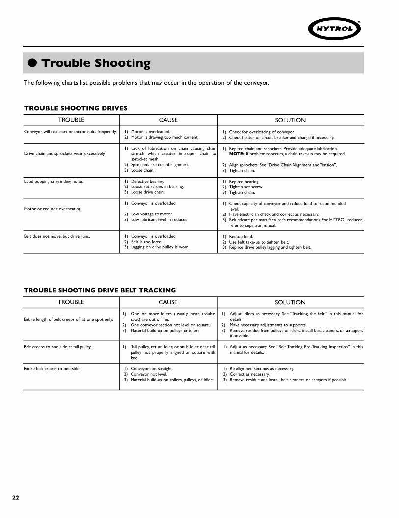
● Trouble ShootingThe following charts list possible problems that may occur in the operation of the conveyor.
TROUBLE SHOOTING DRIVES
TROUBLE CAUSE SOLUTION
Conveyor will not start or motor quits frequently.
Drive chain and sprockets wear excessively.
Loud popping or grinding noise.
Motor or reducer overheating.
Belt does not move, but drive runs.
1) Motor is overloaded.2) Motor is drawing too much current.
1) Lack of lubrication on chain causing chains t retch which creates improper chain tosprocket mesh.
2) Sprockets are out of alignment.3) Loose chain.
1) Defective bearing.2) Loose set screws in bearing.3) Loose drive chain.
1) Conveyor is overloaded.
2) Low voltage to motor.3) Low lubricant level in reducer.
1) Conveyor is overloaded.2) Belt is too loose.3) Lagging on drive pulley is worn.
1) Check for overloading of conveyor.2) Check heater or circuit breaker and change if necessary.
1) Replace chain and sprockets. Provide adequate lubrication.NOTE: If problem reoccurs, a chain take-up may be required.
2) Align sprockets. See “Drive Chain Alignment and Tension”.3) Tighten chain.
1) Replace bearing.2) Tighten set screw.3) Tighten chain.
1) Check capacity of conveyor and reduce load to recommended level.
2) Have electrician check and correct as necessary.3) Relubricate per manufacturer’s recommendations. For HYTROL reducer,
refer to separate manual.
1) Reduce load.2) Use belt take-up to tighten belt.3) Replace drive pulley lagging and tighten belt.
TROUBLE SHOOTING DRIVE BELT TRACKING
TROUBLE CAUSE SOLUTION
Entire length of belt creeps off at one spot only.
Belt creeps to one side at tail pulley.
Entire belt creeps to one side.
1) One or more idlers (usually near troublespot) are out of line.
2) One conveyor section not level or square.3) Material build-up on pulleys or idlers.
1) Tail pulley, return idler, or snub idler near tailpulley not properly aligned or square withbed.
1) Conveyor not straight.2) Conveyor not level.3) Material build-up on rollers, pulleys, or idlers.
1) Adjust idlers as necessary. See “Tracking the belt” in this manual fordetails.
2) Make necessary adjustments to supports.3) Remove residue from pulleys or idlers. install belt, cleaners, or scrappers
if possible.
1) Adjust as necessary. See “Belt Tracking Pre-Tracking Inspection” in thismanual for details.
1) Re-align bed sections as necessary.2) Correct as necessary.3) Remove residue and install belt cleaners or scrapers if possible.

23
● Resolviendo ProblemasLa siguiente gráfica muestra una lista de posibles problemas que pueden ocurrir durante la operación del transportador
RESOLVIENDO PROBLEMAS DE TRANSMISION
PROBLEMA CAUSA SOLUCION
El transportador no arranca o el motor se detienefrecuentemente.
Desgaste excesivo de la cadena motriz ylas catarinas.
Funcionamiento muy ruidoso.
Motor o reductor recalentado.
La banda no se mueve, pero el motor corre.
1) El motor está sobrecargado.2) El motor pasa demasiada corriente.
1) Falta de lubricación en la cadena causando su extensión lo cual crea una cadena inapropiada.
2) Los catarinas están desalineadas.3) La cadena está floja.
1) Rodamientos defectuosos.2) El tornillo candado está flojo en el rodamiento.3) La cadena está floja.
1) Transportador está sobrecargado.2) Bajo voltaje al motor.3) Bajo nivel de lubricante en reductor.
1) El transportador está sobrecargado.2) La banda está floja.3) El revestimiento de la polea motriz esta gastada.
1) Revise si hay sobrecarga del transportador.2) Revise los circuitos e interruptores de protección y sobrecarga, y cámbielos
si es necesario.
1) Reemplace la cadena y las catarinas. Proporcione una adecuadalubricación. NOTA: Si se presentan problemas, posiblemente serequiere tensionar la cadena.
2) Alinee catarinas. Vea “Alineación y Tensión de Cadena Motriz” .3) Tensione la cadena.
1) Reemplace los rodamientos.2) Apriete el tornillo candado.3) Tensione la cadena.
1) Revise la capacidad del transportador y reduzca la carga al nivelrecomendado.
2) Haga un chequeo por un electricista y corrija si es necesario.3) Vuelva a lubricar de acuerdo a las recomendaciones del fabri-
cante. Para el reductor HYTROL, refiérase al manual adjunto.
1) Reduzca la carga.2) Use tensores de banda para apretar la banda.3) Reemplaze el revestimiento de la polea y apriete la banda.
RESOLVIENDO PROBLEMAS DE ALINEACION DE LA BANDA MOTRIZ
PROBLEMA CAUSA SOLUCION
La banda se desliza en un punto.
La banda se desliza hacia un lado en la polea deretorno.
Toda la banda se desliza hacia un lado.
1) Uno o más rodillos (usualmente cerca del puntodel problema) están desalineados.
2) Una o más secciones están desniveladas odesencuadradas.
3) Acumulación de material en rodillos o poleas.
1) La polea de retorno, rodillo de retorno o el rodillode alineación cerca de la polea de retorno noestá alineada o encuadrada con la cama.
1) El transportador no está derecho.2) El transportador no está nivelado.3) Material acumulado en rodillos o poleas.
1) Ajuste los rodillos como sea necesario. Use la sección “Alineación de la banda”como referencia.
2) Ajuste los soportes como sea necesario.3) Remueva el residuo de los rodillos o poleas. Aplique los limpiadores de banda
o raspadores si es posible.
1) Ajuste como sea necesario.Vea “Inspección Pre-Alineación de la Banda” en estemanual.
1) Realinie las secciones de cama como sea necesario.2) Conecte como sea necesario.3) Remueva el residuo y aplique los limpiadores de banda o raspadores si es
posible.

24
● Preventive Maintenance ChecklistThe following is a general maintenance checklist which covers the major components of your conveyor.This will be helpful inestablishing a standard maintenance schedule.
HYTROL Serial Number(Located near Drive onPowered Models).
● How to Order Replacement PartsIncluded in this manual are parts drawings with completereplacement parts lists. Minor fasteners, such as nuts and bolts,are not included.
When ordering replacement parts:Contact Dealer from whom conveyor was purchased ornearest HYTROL Distributor.Give Conveyor Model Number and Serial Number orHYTROL Factory Order Number.Give Part Number and complete description from PartsList.Give type of drive. Example—8” End Drive, 8” CenterDrive, etc.If you are in a breakdown situation, tell us.
1. . .
2. . .
3. . .
4. . .
5. . .
Check NoiseCheck TemperatureCheck Mounting Bolts
Check NoiseCheck TemperatureCheck Oil Level
Check TrackingCheck TensionCheck Lacing
Check NoiseLubricateCheck for Wear
Check TensionCheck for WearCheck for Sheave Alignment
General Check:All loose bolts,e t c. , t i g h t e n e d
Check NoiseCheck Mounting Bolts
Check for WearCheck Set Screws & Keys
SCHEDULESUGGESTED ACTIONCOMPONENT
MOTOR
REDUCER
BELT
DRIVE CHAIN
STRUCTURAL
V-BELTS
BEARINGS(Pulleys & Rollers)
SPROCKETS
Weekly Monthly Quarterly
NOTE: Check Set Screws after the first 24 Hours ofoperation.

25
● Lista de Mantenimiento PreventivoLa siguiente es una lista de verificación de mantenimiento preventivo, la cual cubre los principales componentes de su transportador. Esta lista leserá útil para establecer un programa estándar de mantenimiento.
Número de Serie HYTROL (Localizado cerca a laUnidad Motriz en los modelos motorizados).
● Como Ordenar Partes de RepuestoLos dibujos de las partes con listas completas de las partes derepuesto están incluidos en este manual. Partes tales como tornillosy tuercas no están incluidas.
Para ordenar partes de repuesto:Contacte la persona que le vendió el transportador o eldistribuidor de Hytrol más cercano.Proporcione el Modelo del Transportador y el Número de Serieo Número de la Orden de Fabricación.Proporcione el Número de la parte y descripción completa queaparece en la Lista de Partes de Repuesto.Proporcione el tipo de motor. Ejemplo—Unidad Motriz de 8"en el Extremo, Unidad Motriz Central 8", etc.Si está en una situación crítica, c o mu n í q u e n o s l oinmediatamente.
1. . .
2. . .
3. . .
4. . .
5. . .
COMPONENTE
MOTOR
REDUCTOR
BANDAS
RODAMIENTOS
CADENA MOTRIZ
CATARINAS
BANDAS -V
ESTRUCTURA
REMEDIO
Revisar Ruido
Revisar la Temperatura
Revisar los Tornillos de Montaje
Revisar Ruido
Revisar la Temperatura
Revisar el Nivel del Aceite
Revisar la Alineación
Revisar la Tensión
Revisar el Enlace
Revisar Ruido
Revisar los Tornillos de Montaje
Revisar Ruido
Lubricar
Revisar el Desgaste
Revisar el Desgaste
Revisar los Tornillos y Juegos
Revisar la Tensión
Revisar el Desgaste
Revisar la Alineación de la Polea
Revisión General: Tornillos flojos, etc.
HORARIO
Semanal Mensual Trimestral
NOTA: Revise los tornillos tensores 24 horas despues dela primera operación.

26
● Model TL Parts Drawing (8” End Drive) Dibujo de Pa rtes del Modelo TL (8” Motor de Extre m o )
SECTION “A-A”
4 IN DIA TAIL PULLEY
6 IN DIA TAIL PULLEY

27
Ref. No. Part No. Description1 — Motor—C-Face— 030.7134 1/2 HP—230/460 VAC—3 Ph.—60 Hz.—TEFC— 030.7324 1 HP—230/460 VAC—3 Ph.—60 Hz.—TEFC— 030.7534 2 HP—230/460 VAC—3 Ph.—60 Hz.—TEFC2 — Speed Reducer— R-00153-30L 4AC—RH—30:1 Ratio— R-00164-30L 5AC—RH—30:1 Ratio3 — Coupling Kit—Motor to Reducer— 052.145 (1/2 — 1 HP)— 052.146 (2 HP)4 — Sprocket—Reducer— 028.133 50B14 x 1 in. Bore (4AC)— 028.1342 50B16 x 1-1/4 in. Bore (5AC)5 028.104 Sprocket––Drive Pulley— 028.13832 50B28 x 1-3/16 in. Bore— 028.1115 50B32 x 1-3/16 in. Bore6 029.101 #50 Riveted Roller Chain7 029.201 Connector Link—#50 Roller Chain8 B-00874 8 in. Dia. Drive Pulley (Fully Lagged) (Specify OAW)9 B-01036 Drive Shell Assembly (Specify OAW)10 B-01168 Removable Drive Plate11 010.202 4-Bolt Flange Bearing—1-3/16 in. Bore12 090.203 Shaft Key—1/4 in. Sq. x 1 in. Long13 B-04842 11/16 in. Hex Idler Bracket14 — 2-1/2 in. Dia. Snub Idler— B-17254-093 12 in. OAW— B-17254-125 16 in. OAW— B-17254-141 18 in. OAW— B-17254-157 20 in. OAW— B-17254-189 24 in. OAW— B-17254-237 30 in. OAW— B-17254-285 36 in. OAW— B-17254-333 42 in. OAW— B-17254-381 48 in. OAW— B-17254-429 54 in. OAW15 B-05545 Motor Base Support Angle—RH16 B-05540 Motor Base Support Angle—LH17 B-06629 Motor Base Assembly (Specify OAW)18 040.307 Take-Up Bolt—3/8-16 x 3-1/4 in. Long19 041.300 Hex Jam Nut—Heavy—3/8-1620 B-04070 Chain Guard Front Plate21 B-06262 Chain Guard Back Plate22 098.150 Spacer-13/32 in. I.D. x 3/4 in. O.D. x 3/8 in. Long23 040.31115 Hex Head Bolt, 3/8-16 x 3-1/4 in. Long24 041.200 Hex Jam Nut, 3/8-16 in.25 041.919 Acorn Nut—3/8-16 in.26 093.215 Return Roller Bracket27 B-06742 2-1/8 in. Dia. Snub Idler (Specify OAW)28 B-01884 Bed Spacer Assembly (Specify OAW)29 — 4 ft. Long Bed— B-04351 12 in. thru 20 in. OAW (Specify)— B-05592 24 in. thru 42 in. OAW (Specify)— — 5 ft. Long Bed— B-02420 12 in. thru 20 in. OAW (Specify)— B-02421 24 in. thru 42 in. OAW (Specify)— B-15931 48 in. & 54 in. OAW-Drive/Int. Section (Specify OAW)— B-15932 48 in. & 54 in. OAW-Tail Section (Specify OAW)— — 6 ft. Long Bed— B-01254 12 in. thru 20 in. OAW (Specify)— B-01257 24 in. thru 42 in. OAW (Specify)— — 7 ft. Long Bed— B-21654 12 in. thru 20 in. OAW (Specify)— B-21655 24 in. thru 42 in. OAW (Specify)— — 8 ft. Long Bed— B-01255 12 in. thru 20 in. OAW (Specify)
Ref. No. Part No. Description— B-01258 24 in. thru 42 in. OAW (Specify)— — 9 ft. Long Bed— B-21656 12 in. thru 20 in. OAW (Specify)— B-21657 24 in. thru 42 in. OAW (Specify)— — 10 ft. Long Bed— B-01256 12 in. thru 20 in. OAW (Specify)— B-02302 24 in. thru 42 in. OAW (Specify)30 B-00163 Spice Plate31 B-21347-R Attachment Plate Assembly—RH32 B-21347-L Attachment Plate Assembly—LH33 040.407 Take-Up Bolt—1/2-13 x 4 in. Long34 041.201 Hex Jam Nut—1/2-1335 042.919 Shoulder Bolt, 1/2 in. Dia. x .312 Long36 B-09508 1.9 in. Dia. Return Idler (Specify OAW)37 — Tail Pulley— B-22221 4 in. Dia.12 in. thru 30 in. OAW (Specify)— B-21752 6 in. Dia. 36 in. thru 54 in. OAW (Specify)38 — Bearing Spacer— B-07987 4 in. Dia. Pulley— B-02042 6 in. Dia. Pulley39 — Take-Up Plate Assembly—RH— B-21349-R 12 in. thru 30 in. OAW— B-21351-R 36 in. thru 54 in. OAW40 — Take-Up Plate Assembly—LH— B-21349-L 12 in. thru 30 in. OAW— B-21351-L 36 in. thru 54 in. OAW41 — 3-Bolt Flange Bearing— 010.102 1 in. Bore— 010.103 1-3/16 in. Bore42 — Nip Point Guard—Tail End— B-09859 12 in. thru 30 in. OAW (Specify)— B-09860 36 in. thru 54 in. OAW (Specify)43 — Belt—Black Ultimate 140 BOS (Specify Width)44 — U3 Clipper Unibar Belt Lacing (Specify Length)45 — #13 Lacing Pin (Specify Length)46 B-12345 Snub Roller Guard (Specify OAW)47 B-12346 Snub Roller Guard Mounting Bracket48 B-13707 Snub Roller Guard (Specify OAW)49 B-13708 Snub Roller Guard Mounting Bracket50 049.310 U-Type Speed Nut—1/4-2051 — MS Type Pivot Plate—1-1/2 in. Flange— B-00913 3-11/16 in. High— B-02112 1-9/16 in. High52 — Floor Support Frame— B-00914 6 in. High (Specify OAW)— B-12777 7 in. High (Specify OAW)— B-12778 8 in. High (Specify OAW)— B-00915 9 in. High (Specify OAW)— B-00916 11-1/2 in. High (Specify OAW)— B-00917 14-1/2 in. High (Specify OAW)— B-02098 18-1/2 in. High (Specify OAW)— B-00919 22-1/2 in. High (Specify OAW)— B-00921 32-1/2 in. High (Specify OAW)— B-00923 44-1/2 in. High (Specify OAW)— B-00925 56-1/2 in. High (Specify OAW)— B-02107 68-1/2 in. High (Specify OAW)— B-02109 78-1/2 in. High (Specify OAW)— B-02111 90-1/2 in. High (Specify OAW)53 B-00911 Adjustable Foot Assembly (Specify Length)54 — Attachment Bar for Drive End Support— B-09453 Non Adjustable (Not Shown)— B-09454 Adjustable
See Page 24 for Information on HowTo Order Replacement Parts
Recommended Spare PartsHighlighted In Gray
Vea la Página 25 para información sobre como ordenarpartes de repuesto
Partes de Repuesto Recomendadasse Resaltan en Gris
OAW
● Model TL Parts List (8” End Drive) Lista de Pa rtes del Modelo TL (8” Motor de Extre m o )

28
See Page 30 For Center Drive
SECTION “A-A”
● Model TL Parts Drawing (8” Center Drive) Dibujo de Pa rtes del Modelo TL (8” Motor Centra l )

29
● Model TL Parts List (8” Center Drive)Lista de Partes del Modelo TL (8” Motor Central)
Ref. No. Part No. Description1 — Bed Assembly—11'/11'-4" OAL Conv. Only (Specify OAW)— B-01256 12” thru 20” OAW (Specify)— B-02302 24” thru 42” OAW (Specify)2 B-01536 Belt Protector3 — 4 ft. Long Bed— B-04351 12 in. thru 20 in. OAW (Specify)— B-05592 24 in. thru 42 in. OAW (Specify)— — 5 ft. Long Bed— B-02420 12 in. thru 20 in. OAW (Specify)— B-02421 24 in. thru 42 in. OAW (Specify)— B-15931 48 in. & 54 in. OAW Drive/Int Section (Specify OAW)— B-15932 48 in. & 54 in. OAW Tail Section (Specify OAW)— — 6 ft. Long Bed— B-01254 12 in. thru 20 in. OAW (Specify)— B-01257 24 in. thru 42 in. OAW (Specify)— — 7 ft. Long Bed— B-21654 12 in. thru 20 in. OAW (Specify)— B-21655 24 in. thru 42 in. OAW (Specify)— — 8 ft. Long Bed— B-01255 12 in. thru 20 in. OAW (Specify)— B-01258 24 in. thru 42 in. OAW (Specify)— — 9 ft. Long Bed— B-21656 12 in. thru 20 in. OAW (Specify)— B-21657 24 in. thru 42 in. OAW (Specify)— — 10 ft. Long Bed— B-01256 12 in. thru 20 in. OAW (Specify)— B-02302 24 in. thru 42 in. OAW (Specify)4 B-01884 Bed Spacer Assembly (Specify OAW)5 B-00163 Splice Plate6 093.215 Return Roller Bracket7 B-06742 2-1/8 in. Dia. Snub Idler (Specify OAW)8 B-09508 1.9 in. Dia. Return Idler (Specify OAW) (Not Shown)9 B-21347-R Attachment Plate Assembly—RH10 B-21347-L Attachment Plate Assembly—LH11 040.407 Take-Up Bolt—1/2-13 x 4 in. Long12 041.201 Hex Jam Nut—1/2-1313 042.919 Shoulder Bolt—1/2 in. Dia. x .312 Long14 041.919 Acorn Hex Nut—3/8-16 in.15 — Tail Pulley— B-22221 4 in. Dia.—12 in. thru 30 in. OAW (Specify)— B-21752 6 in. Dia.—36 in. thru 54 in. OAW (Specify)
Ref. No. Part No. Description16 — Bearing Spacer— B-07987 4 in. Dia. Pulley— B-02042 6 in. Dia. Pulley17 — Take-Up Plate Assembly—RH— B-21349-R 12 in. thru 30 in. OAW— B-21351-R 36 in. thru 54 in. OAW18 — Take-Up Plate Assembly—LH— B-21349-L 12 in. thru 30 in. OAW— B-21351-L 36 in. thru 54 in. OAW19 — 3-Bolt Flange Bearing— 010.102 1 in. Bore— 010.103 1-3/16 in. Bore20 — Nip Point Guard— B-09859 12 in. thru 30 in. OAW (Specify)— B-09860 36 in. thru 54 in. OAW (Specify)21 — Belt—Black Ultimate 140 BOS (Specify Width)22 — U3 Clipper Unibar Belt Lacing (Specify Length)23 — #13 Lacing Pin (Specify Length)24 B-13708 Snub Roller Guard (Specify OAW)25 B-13707 Snub Roller Guard Mounting Bracket26 049.310 U-Type Speed Nut—1/4-2027 — MS Type Pivot Plate—1-1/2 in. Flange— B-00913 3-11/16 in. High— B-02112 1-9/16 in. High28 — Floor Support Frame— B-00914 6 in. High (Specify OAW)— B-12777 7 in. High (Specify OAW)— B-12778 8 in. High (Specify OAW)— B-00915 9 in. High (Specify OAW)— B-00916 11-1/2 in. High (Specify OAW)— B-00917 14-1/2 in. High (Specify OAW)— B-02098 18-1/2 in. High (Specify OAW)— B-00919 22-1/2 in. High (Specify OAW)— B-00921 32-1/2 in. High (Specify OAW)— B-00923 44-1/2 in. High (Specify OAW)— B-00925 56-1/2 in. High (Specify OAW)— B-02107 68-1/2 in. High (Specify OAW)— B-02109 78-1/2 in. High (Specify OAW)— B-02111 90-1/2 in. High (Specify OAW)29 B-00911 Adjustable Foot Assembly (Specify Length)
BELT WIDTH 6” 10” 12” 14” 18” 24” 30” 36” 42” 48”BED WIDTH 12” 16” 18” 20” 24” 30” 36” 42” 48” 54”
OAW
See Page 24 for Information on HowTo Order Replacement Parts
Recommended Spare PartsHighlighted In Gray
Vea la Página 25 para información sobre como ordenarpartes de repuesto
Partes de Repuesto Recomendadasse Resaltan en Gris

30
● 8” Center Drive Assembly Ensamble de la Unidad Motriz Central 8”
Ref. No. Part No. Description1 — Motor-C-Face— 030.7134 1/2 HP—230/460 VAC—3 Ph.—60 Hz.—TEFC— 030.7324 1 HP—230/460 VAC—3 Ph.—60 Hz.—TEFC— 030.7534 2 HP—230/460 VAC—3 Ph.—60 Hz.—TEFC2 — Speed Reducer— R-00153-30R 4AC—RH—30:1 Ratio— R-00164-30R 5AC—RH—30:1 Ratio3 — Coupling Kit-Motor To Reducer— 052.145 (1/2 — 1 HP)— 052.146 (2 HP)4 — Sprocket-Reducer— 028.133 50B14 x 1 in. Bore (4AC)— 028.1342 50B16 x 1-1/4 in. Bore (5AC)5 — Sprocket—Drive Pulley— 028.13832 50B28 x 1-3/16 in. Bore— 028.1115 50B32 x 1-3/16 in. Bore6 029.101 #50 Riveted Roller Chain7 029.201 Connector Link—#50 Roller Chain8 B-02021 8" Dia. Ctr. Dr. Pulley (Fully Lagged) (Sp. Dr.Width)9 B-05961 Drive Plate Assembly—RH10 B-05963 Drive Plate Assembly—LH11 010.202 4-Bolt Flange Bearing—1-3/16 in. Bore12 090.203 Shaft Key—1/4 in. Sq. x 1 in. Long13 B-05946 Motor Base Support Angle Assembly14 B-18670-R Motor Support Assembly15 B-06629 Motor Base Assembly (Specify Drive Width)16 B-05965 Take-Up Bracket17 040.307 Take-Up Bolt—3/8-16 x 2-1/4 in. Long18 041.300 Hex Jam Nut—Heavy-3/8-1619 B-05949 Chain Guard Assembly
Ref. No. Part No. Description20 040.309 Hex Thin Head Cap Screw—3/8-16 x 3 in. Long21 041.200 Hex Jam Nut 3/8-1622 041.919 Acorn Nut—3/8-1623 B-04842 11/16 in. Hex Idler Bracket24 B-17254 2-1/2" Dia. Heavy Duty Snub Idler (Specify BR)25 B-03916 Bed Spacer (Specify Drive Width)26 040.411 Take-Up Bolt—1/2-13 x 9 in. Long27 041.201 Hex Jam Nut—1/2-1328 — Take-Up Pulley— B-22323 4 in. Dia. - 12 in. thru 18 in. Drive Width (Specify)— B-05904 4 in. Dia. - 20 in. thru 28 in. Drive Width (Specify)— B-21755 6 in. Dia. - 30 in. thru 54 in. Drive Width (Specify)29 — 3 Bolt Flange Bearing— 010.102 4 in. Pulley - 1 in. Bore— 010.103 6 in. Pulley - 1-3/16” Bore30 — Take-Up Plate Assembly
— B-05958 4 in.Take-Up Pulley— B-12480 6 in.Take-Up Pulley31 B-05966 Upper Bearing Guide32 B-04655 Bearing Guide Spacer33 B-04161 Bearing Guide34 B-08336 Rear Guard (Specify Drive Width)35 B-08335 Bottom Guard (Specify Drive Width)36 B-08337 Bottom Angle Guard (Specify Drive Width)37 B-08338-R Side Guard-RH38 B-08338-L Side Guard-LH39 B-08339 Formed Clip40 049.310 U-Type Speed Nut-1/4-20
See Page 24 for Information on How To Order Replacement Parts
Recommended Spare Parts Highlighted In Gray
Vea la Página 25 para información sobre como ordenar partes de repuesto
Partes de Repuesto Recomendadas se Resaltan en Gris

31
● Underside Take-Up AssemblyEnsamble del Tensor Inferior
Ref. No. Part No. Description1 B-04842 Mounting Bracket - 11/16 in. Hex Idler2 B-05477 Threated Sect. Spacer (Specify BR)3 B-05966 Upper Bearing Guide4 B-07987 Bearing Spacer - 3 Bolt Flange Bearing, 1 in. B5 B-09844-L Side Channel Assembly - LH, Low Profile Take-Up6 B-09844-R Side Channel Assembly - RH, Low Profile Take-Up7 B-09848 Rear Guard - 4 in. Low Profile Take-Up (Specify OAW)8 B-09849 Bottom GD - 4 in. Low Profile Take-Up (Specify OAW)9 B-09850 BTM Angle GD - 4 in. Low Profile Take-Up (Specify OAW)10 B-09851-L Side Guard - LH 4 in. Low Profile Take-Up11 B-09851-R Side Guard - RH 4 in. Low Profile Take-Up12 B-09852-L Take-Up Plate Assembly - LH Low Profile13 B-09852-R Take-Up Plate Assembly - RH Low Profile
Ref. No. Part No. Description14 B-17254 2-1/2 in. OD Snub Rlr Assembly-BCA BRG (Specify BR)15 — 4 in. Dia. Pulley Assembly - System Ends (Specify OAW)— B-22323 10 in. thru 18 in. OAW (Specify)— B-05904 20 in. thru 42 in. OAW (Specify)16 010.0021 Bearing - Cast Iron, 2-Bolt, 1 in. Bore17 010.102 Bearing - Cast Iron, 3-Bolt, 1 in. Bore18 040.411 1/2-13 x 9 in. Lg. Hex Bolt-Fully Threaded19 041.201 1/2-13 NC2B Hex Jam Nut20 042.2009 5/16-18 x 1 in. Lg. Flat head Bolt21 042.300 1/4-20 x 1/2 in. Lg Truss Head Bolt23 042.557 5/16-18 x 1-1/4 in. Lg Carriage Bolt24 049.310 1/4-20 U-Type Speed Nut
See Page 24 For Information On How to Order Replacement Parts
Recommended Spare Parts List Highlighted in Gray
Vea la Página 25 para información sobre como ordenar partes de repuesto
Partes de Repuesto Recomendadas se Resaltan en Gris

32
● Model TL Stan d ard End Power Feeder Parts Drawing Dibujo de Pa rtes del Alimentador Motriz Estándar TL
@:>----#--+I·
�z �
/ �
0
0
0
0 0
0
0
\,
\� 0
0
0
0 a
0
0
'
_ _ _ _ _ _ /
�YTRO�

Ref. No. Part No. Description— B-21349-R 4 in. Pulley— B-21351-R 6 in. Pulley25 — Feeder Take-Up Plate—LH— B-21349-L 4 in. Pulley— B-21351-L 6 in. Pulley26* — Gravity Bracket— B-02623 4 in. Pulley— B-06210 6 in. Pulley27 B-02624 Gravity Bar 12 in. thru 28 in. OAW (Specify)28 B-02912 1 in. Dia. Pop-Out Rlr. 12 in. thru 30 in. OAW (Specify)29 091.110 Cable Assembly30 — Bearing Spacer— B-07987 4 in. Dia. Pulley— B-02042 6 in. Dia. Pulley31 B-06742 2-1/8 in. Dia. Snub Roller (Specify OAW)32 093.215 Return Roller Bracket33 — Snub Roller Guard— B-14443 4 in. Pulley 12 in. thru 24 in. OAW (Specify)— B-13708 6 in. Pulley 30 in. thru 42 in. OAW (Specify)34 — Snub Roller Guard Mounting Bracket— B-14445 4 in. Pulley— B-13707 6 in. Pulley35 049.310 U-Type Speed Nut—1/4-2036 040.407 Take-Up Bolt—1/2-13 x 4 in. Long37 041.201 Hex Jam Nut—1/2-1338 B-01884 Bed Spacer Assembly 30 in. thru 42 in. OAW (Specify)39 — Belt—Black Ultimate 140 BOS (Specify Width)40 — U3 Clipper Unibar Belt Lacing (Specify Length)41 — #13 Lacing Pin (Specify Length)42 — Nip Point Guard— B-18909 4 in. Pulley 12 in. thru 24 in. OAW (Specify)— B-21576 6 in. Pulley 30 in. thru 42 in. OAW (Specify)43 — MS Type Pivot Plate—1-1/2 in. Flange— B-00913 3-11/16 in. High— B-02112 1-9/16 in. High44 — Floor Support Frame— B-00914 6 in. High (Specify OAW)— B-12777 7 in. High (Specify OAW)— B-12778 8 in. High (Specify OAW)— B-00915 9 in. High (Specify OAW)— B-00916 11-1/2 in. High (Specify OAW)— B-00917 14-1/2 in. High (Specify OAW)— B-02098 18-1/2 in. High (Specify OAW)— B-00919 22-1/2 in. High (Specify OAW)— B-00921 32-1/2 in. High (Specify OAW)— B-00923 44-1/2 in. High (Specify OAW)— B-00925 56-1/2 in. High (Specify OAW)— B-02107 68-1/2 in. High (Specify OAW)— B-02109 78-1/2 in. High (Specify OAW)— B-02111 90-1/2 in. High (Specify OAW)45 B-00911 Adjustable Foot Assembly (Specify Length)
BELT WIDTH 6” 8” 10” 12” 14” 16” 18” 20” 24” 30”BED WIDTH 10” 12” 14” 16” 18” 20” 22” 24” 28” 34”
See Page 24 for Information on How To Order Replacement Parts
Recommended Spare Parts Highlighted In Gray
Vea la Página 25 para información sobre como ordenar partes de repuesto
Partes de Repuesto Recomendadas se Resaltan en Gris
Ref. No. Part No. Description1 — Bed Assembly— B-21387 18 in. Long 12 in. thru 18 in. OAW (Specify)— B-21641 33 in. Long 18 in. thru 20 in. OAW (Specify)— B-20078 33 in. Long 24 in. OAW— B-05592-030 48 in. Long 30 in. OAW— B-02421-036 60 in. Long 36 in. OAW— B-01257-042 72 in. Long 42 in. OAW2 — Conveyor Tail Pulley— B-22222 4 in. Dia. 12 in. thru 24 in. OAW (Specify)— B-22101 6 in. Dia. 30 in. thru 42 in. OAW (Specify)3 — Feeder Drive Pulley— B-22222 4 in. Dia. 12 in.Thru 24 in. OAW (Specify)— B-22101 6 in. Dia. 30 in. thru 42 in. OAW (Specify)4 — Feeder Tail Pulley— B-22221 4 in. Dia. 12 in. thru 24 in. OAW (Specify)— B-21752 6 in. Dia. 30 in. thru 42 in. OAW (Specify)5 — 3-Bolt Flange Bearing— 010.102 1 in. Bore (4 in. Pulley)— 010.103 1-3/16 in. Bore (6 in. Pulley)6 — Sprocket— 028.133 50B14 x 1 in. Bore (4 in. Pulley)— 028.1341 50B16 x 1-3/16 in. Bore (6 in. Pulley)7 090.203 Shaft Key—1/4 in. Sq. x 1 in. Long8 029.101 #50 Riveted Roller Chain9 029.201 Connector Link—#50 Roller Chain11 — Pivot Bracket—LH— B-06168 4 in. Pulley— B-06172 6 in. Pulley12 — Chain Guard— B-06174-001 4 in. Pulley— B-06179-001 6 in. Pulley13 040.3122 Hex Thin Head Bolt, 3/8-16 x 4 in. Long (4 in. Pulley)14 041.200 Hex Jam Nut 3/8-1615 041.919 Acorn Nut 3/8-1616 — Feeder Drive Plate—RH— B-09759-R 4 in. Pulley— B-09758-R 6 in. Pulley17 — Feeder Drive Plate—LH— B-09759-L 4 in. Pulley— B-09758-L 6 in. Pulley18 — Conveyor Take Up Plate—RH— B-09813-R 4 in. Pulley— B-09758-R 6 in. Pulley19 — Conveyor Take Up Plate—LH— B-09813-L 4 in. Pulley— B-09758-L 6 in. Pulley20 — Nip Point Guard— B-09859 4 in. Pulley 12 in. thru 24 in. OAW (Specify)— B-09860 6 in. Pulley 30 in. thru 42 in. OAW (Specify)21 B-21347-R Attachment Plate Assembly. R.H.22 B-21347-L Attachment Plate Assembly L.H.23 042.919 Shoulder Bolt, 1/2 in Dia. x .312 Long24 — Feeder Take-Up Plate RH
33
● Model TL Standard End Power Feeder Parts List Lista de Partes del Alimentador Motriz Estándar TL
* Bearing Spacer supplied if Gravity Brackets are not used.

34
● Model TL System End Power Feeder Parts Draw i n gDibujo de Pa rtes del Alimentador Motriz de Sistema TL
4” TAIL PULLEY
6”TAIL PULLEY

Ref. No. Part No. Description— B-20642 6 in. Pulley25 — Nip Point Guard— B-14926 4 in. Pulley 12 in. thru 24 in. OAW (Specify)— B-21895 6 in. Pulley 30 in. thru 42 in. OAW (Specify)26 — Nip Point Guard Mounting Bracket—RH— B-14533-R 4 in. Pulley— B-14535-R 6 in. Pulley27 — Nip Point Guard Mounting Bracket—LH— B-14533-L 4 in. Pulley— B-14535-L 6 in. Pulley28 B-01982 1.9 in. Dia. Roller 9 in. thru 21 in. BR (Specify)29 B-05034 Bottom Guide—4 in. Pulley Only30 B-14624 Spacer—6 in. Pulley Only31 B-14623 Guide—6 in. Pulley Only32 B-20445 1 in. Dia. Pop-Out Roller (Specify BR)33 090.262 Pop-Out Roller Bracket34 091.110 Cable Assembly35 090.107 Hog Ring36 — Take-Up Bolt— 040.407 1/2-13 x 4 in. Long—4 in. Pulley— 040.4061 1/2-13 x 3 in. Long—6 in. Pulley37 041.201 Hex Jam Nut—1/2-1338 B-05477 Threaded Section Spacer 27" thru 39" BR (Specify)39 B-06742 2-1/8 in. Dia. Snub Roller (Specify OAW)40 093.215 Return Roller Bracket41 — Snub Roller Guard— B-14443 4 in. Pulley 12 in. thru 24 in. OAW (Specify)— B-13708 6 in. Pulley 30 in. thru 42 in. OAW (Specify)42 — Snub Roller Guard Mounting Bracket— B-14445 4 in. Pulley— B-13707 6 in. Pulley43 049.310 U-Type Speed Nut—1/4-2044 B-01884 Bed Spacer Assembly 30 in,. thru 42 in. OAW (Specify)45 — Nip Point Guard— B-18909 4 in. Pulley 12 in. thru 24 in. OAW (Specify)— B-21576 6 in. Pulley 30 in. thru 42 in. OAW (Specify)46 — Belt—Black Ultimate 140 BOS (Specify Width)47 — U3 Clipper Unibar Belt Lacing (Specify Length)48 — #13 Lacing Pin (Specify Length)49 — MS Type Pivot Plate—1-1/2 in. Flange— B-00913 3-11/16 in. High— B-02112 1-9/16 in. High50 — Floor Support Frame— B-00914 6 in. High (Specify OAW)— B-12777 7 in. High (Specify OAW)— B-12778 8 in. High (Specify OAW)— B-00915 9 in. High (Specify OAW)— B-00916 11-1/2 in. High (Specify OAW)— B-00917 14-1/2 in. High (Specify OAW)— B-02098 18-1/2 in. High (Specify OAW)— B-00919 22-1/2 in. High (Specify OAW)— B-00921 32-1/2 in. High (Specify OAW)— B-00923 44-1/2 in. High (Specify OAW)— B-00925 56-1/2 in. High (Specify OAW)— B-02107 68-1/2 in. High (Specify OAW)— B-02109 78-1/2 in. High (Specify OAW)— B-02111 90-1/2 in. High (Specify OAW)51 B-00911 Adjustable Foot Assembly (Specify Length)
Ref. No. Part No. Description1 — Bed Assembly— B-21387 18 in. Long 12 in. thru 18 in. OAW (Specify)— B-21641 33 in. Long 20 in. thru 24 in. OAW (Specify)— B-05592-030 48 in. Long 30 in. OAW— B-02421-036 60 in. Long 36 in. OAW— B-01257-042 72 in. Long 42 in. OAW2 — Conveyor Tail Pulley— B-22222 4 in. Dia. 12 in. thru 24 in. OAW (Specify)— B-22101 6 in. Dia. 30 in. thru 42 in. OAW (Specify)3 — Feeder Drive Pulley— B-22222 4 in. Dia. 12 in. thru 24 in. OAW (Specify)— B-22101 6 in. Dia. 30 in. thru 42 in. OAW (Specify)4 — Feeder Tail Pulley— B-22323 4 in. Dia. 12 in. thru 24 in. OAW (Specify)— B-21755 6 in. Dia. 30 in. thru 42 in. OAW (Specify)5 — 3-Bolt Flange Bearing— 010.102 1 in. Bore (4 in. Pulley)— 010.103 1-3/16 in. Bore (6 in. Pulley)6 — Sprocket— 028.133 50B14 x 1 in. Bore (4 in. Pulley)— 028.1341 50B16 x 1-3/16 in. Bore (6 in. Pulley)7 090.203 Shaft Key—1/4 in. Sq. x 1 in. Long8 029.101 #50 Riveted Roller Chain9 029.201 Connector Link—#50 Roller Chain11 — Pivot Bracket—LH— B-06168 4 in. Pulley— B-06172 6 in. Pulley12 — Chain Guard— B-06174-001 4 in. Pulley— B-06179-001 6 in. Pulley13 040.3122 Hex Thin Head Bolt, 3/8-16 x 4 in. Long (4 in. Pulley)14 041.200 Hex Jam Nut 3/8-1615 041.919 Acorn Nut 3/8-1616 — Feeder Drive Plate—RH— B-09759-R 4 in. Pulley— B-09758-R 6 in. Pulley17 — Feeder Drive Plate—LH— B-09759-L 4 in. Pulley— B-09758-L 6 in. Pulley18 — Conveyor Take Up Plate—RH— B-09813-R 4 in. Pulley— B-09758-R 6 in. Pulley19 — Conveyor Take Up Plate—LH— B-09813-L 4 in. Pulley— B-09758-L 6 in. Pulley20 — 2-Bolt Flange Bearing— 010.0021 1 in. Bore (4 in. Pulley)— 010.003 1-3/16 in. Bore (6 in. Pulley)21 — Feeder Take-Up Plate—RH— B-14538-R 4 in. Pulley— B-14545 6 in. Pulley22 — Feeder Take-Up Plate—LH— B-14538-L 4 in. Pulley— B-14545 6 in. Pulley23 — Feeder Take-Up Channel—RH— B-20639 4 in. Pulley— B-20641 6 in. Pulley24 — Feeder Take-Up Channel—LH— B-20640 4 in. Pulley
35
● Model TL System End Power Feeder Parts List Lista de Partes del Alimentador Motriz de Sistema TL
See Page 24 for Information on How To Order Replacement Parts
Recommended Spare Parts Highlighted In Gray
Vea la Página 25 para información sobre como ordenar partes de repuesto
Partes de Repuesto Recomendadas se Resaltan en Gris

HYTROL CONVEYOR COMPANY, INC.2020 Hytrol Drive
Jonesboro, Arkansas 72401USA
Phone: (870) 935-3700
EFFECTIVE OCTOBER 2006Printed in the USA by Master Printing 10/06
www.hytrol.com


