Embed Size (px)
Citation preview

Do-it-yourself Solar Thermal Heating Project-Poquoson, VA
July 2011 – April 2012

Motivation for Project
1. Explore solar technology, benefit from tax
incentives
2. Exercise my engineering skills
3. Be productive rather than watching TV
4. Improve comfort while watching TV, etc.

Electric Power Consumption
-
500
1,000
1,500
2,000
2,500
3,000
3,500
4,000
Jan Feb Mar Apr May Jun Jul Aug Sep Oct Nov Dec
2004
2005
2006
2007
2008
2009
2010
2011
2012
Average
Air conditioning costs low compared to heating costs, so design system to reduce winter heating loads.
Try a low-cost DIY radiant heat system rather than expensive (~$30K) photovoltaics.
Kilo
Wa
tt-h
rs

System Block Diagram*
*Design from www.BuildItSolar.com. See part list at end of charts.
** Analyzed using Uponor Advanced Design Software
Radiant Heat System** Thermal
Reservoir
Solar
Collector
System
9
20

Theory of Control
Enter
desired
room
temp
Collector
Pump = ON
Collector
Pump = OFF
Rad Heat
Pump = OFF
Rad Heat
Pump = ON
Start
Collector
Control
Loop
Start
Radiant
Heat
Control
Loop
Ttank<
(Tcollector
+30°F)?
YES
NO
Ttank>
(Troom+
30°F)?
NO
YES
Troom<
desired
?
YES
NO
Setback
timer =
ON?
NO
YES

3D CAD Model-Google SketchUp
Collector Panels
Reservoir, Circulators & Controllers
Radiant Heat Circuits-family room, kitchen, laundry room, ½ bath
Hot Water Heater
(ref only)
Radiant Heat Manifold

Solar Collector Installation-
15° East of True South, 15° Elevation* from Horizontal
Before After
*vertical orientation maximizes collection in winter, minimizes in summer when unused

Reservoir Installation in Garage
BeforeAfter
• 250 gal of tap water• Vented to atmosphere

Radiant Heat Distribution Manifold
Installation in Coat Closet
Circuit Flow Adjustors
Manifold Shutoff Valves, 2 places
Pressure Pump for initial leak check only

Radiant Heat Installation:610 sq ft: 2 Loops in Family Room, 1 in Kitchen, 1 in laundry room / bathroom
Joist Trak plates for ½” PEX tubing

Operator InterfacesCollector Circulator
Pump Controller
Main Shutoff Switch
Radiant Heat Circulator
Shutoff Switch
Mixing Valve
Thermostat-Storage Tank
Thermostat-Room
Pump Isolation Valves, 4 places
Fill / Drain Ports, 2 places
Electrical Power Plug
Setback Timer

Project Management
• 9 month duration
• $6,565 material costs
• 288 man-hours,
– Essentially by a single worker
– Online research time was significant, but is not
included

Timeline of Project

Cost of Materials = $6,565

Manhours
• 4 hrs / day worked, over 73 work days, by a single workman
• Band joist insul = 12.0 hrs for 95.5 linear ft = 8 linear ft / hr
• Rad heat instl = 73.9 hrs for 610 sq ft = 8.3 sq ft / hr
• Instl Manifold Feed Lines = 13.0 hrs
• Fab collector assemblies = 59.2 hrs = 19.7 hrs / assy
• Installation collector assemblies = 35.8 hrs = 11.9 hrs / instl
• Fab Reservoir = 20.7 hrs
• Fab Circulator Pallet = 42.0 hrs
• Collector Plumbing = 19.1 hrs
Total labor = 288 man-hrs

Performance of System:
• Predicted performance of Collectors and
Radiant Heat System
• Data collection
• Analysis
– Collection efficiency: overall, seasonal
– Heating of house
– Cost recovery
– Reliability and Maintainability

Solar Obscuration MeasurementsJune 2011, 5’ above ridgeline of garage roof, x = 4’ out from 2nd story wall
Our Trees
0
5
10
15
20
25
30
35
40
45
0 50 100 150 200 250 300
Azimuth, deg from True North
Ele
vati
on
, d
eg
rees f
rom
Hz
Ridgeline = 166°
Trees on Property
Line
Neighbor’s Tree
Trees on Property
Line

Predicted Energy Gatheringfrom comparable commercial collector
Norfolk Intl Airport, Viessman Vitosol 200F Power Output vs. Season
Moving Average of Previous 10 days,
T in=113F, T out=122F, Collector Az=-15 deg, Collector Elev=75deg,
1991-2005 Average = 442 BTU/sq ft/day
0
100
200
300
400
500
600
700
800
900
1000
1 31 61 91 121 151 181 211 241 271 301 331 361Day of Year
Po
wer
Ou
tpu
t, B
TU
/sq
ft/
da
y
Max
Median
Min
http://andyschroder.com/SolarEnergyResearch/SolarCollectorPowerOutput/
For three 4’x8’ collectors = 42,432 BTU/day

Predicted Heating Performance
• Calculated using free Advanced Design Suite software from Uponor– 68°F room temp, 24°F outdoor temp, 23 mph wind
– 630 sq ft, average construction, Tin-Tout≤10°
– 7,540 BTU/hr required = 1.8 gal/min @ 109°F
• Given predicted collector performance of 42,432 BTU/day, we’ll get 5.6 hrs of 68°F room temp each day.
• Existing heat pump runs in parallel. – Solar heat setpoint 2° above heat pump to draw from solar
first
– Degree of interaction unknown

Data Acquisition System• Solely for initial testing, the removed
• Arduino based data logger
– Real Time Clock for time stamping
– SD Card Reader module for data
storage
– Cost approximately $60
• Dataset includes
– Temp of room
– Temp of H20 in Reservoir
– Outdoor Temp
– Temp in Garage
– Insolation on Collectors
– Radiant Heat Status (ON/OFF)
– Time of day

Design Flaw = Freeze Up
• 23 Jan 2013 Overnight temp = 18 deg F• Eastern & western collectors froze & split pipes. No leak in center collector.• Pumped tank dry
Flawed Design
Corrected Design7-28-2013
Drain back level
Trap precludes breaking siphon, therefore NO DRAIN BACK!
Burst,3 places
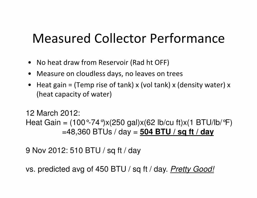
Measured Collector Performance
• No heat draw from Reservoir (Rad ht OFF)
• Measure on cloudless days, no leaves on trees
• Heat gain = (Temp rise of tank) x (vol tank) x (density water) x
(heat capacity of water)
12 March 2012:Heat Gain = (100°-74°)x(250 gal)x(62 lb/cu ft)x(1 BTU/lb/°F)
=48,360 BTUs / day = 504 BTU / sq ft / day
9 Nov 2012: 510 BTU / sq ft / day
vs. predicted avg of 450 BTU / sq ft / day. Pretty Good!
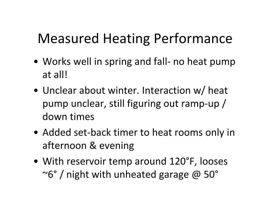
Measured Heating Performance
• Works well in spring and fall- no heat pump
at all!
• Unclear about winter. Interaction w/ heat
pump unclear, still figuring out ramp-up /
down times
• Added set-back timer to heat rooms only in
afternoon & evening
• With reservoir temp around 120°F, looses
~6° / night with unheated garage @ 50°

Was Project Successful?1. Explore solar technology, benefit from tax incentives
– Learned much about solar technology, only got minimal tax break for insulating floor
2. Exercise my engineering skills
– YES! Design / build / test of plumbing, electrical, carpentry, controls, data logging
3. Be productive rather than watching TV
– Yes. Watched little TV during the project
4. Improve comfort while watching TV, etc.
– Yes. Den / kitchen was 60-62°F in winter, now 66-68°F

Items in Block DiagramItem # Description Make Model Cost
1 Solar Collector self self $ 483.00
2 Tubing PEX 3/4 diam $ 0.46
3 Pump, Collector Taco 009-SF5 $ 326.00
4 Sensor, Coll'r Temp incl w/ Steca - -
5 Water God Tap -
6 Tubing PEX 3/4 diam $ 0.46
7 Tubing PEX 3/4 diam $ 0.46
8 Valve, Mixing Honeywell AM101-US-1 $ 75.00
9 Pump Rad Ht Grundfos UP15-29SF $ 164.00
10 Manifold, Supply RHT FN5-4-90 $ 129.00
11 Manifold, Return incl w/ supply mfld - -
12 Rad Ht Loop PEX & Joist Track 1/2 diam $0.89 / ft
13 T'stat, Tank Johnson Controls A419ABC-1C $ 56.75
14 T'stat, Room Johnson Controls A419ABC-1C $ 56.75
15 Controller, Collector Steca/Solene TR 0301 U $ 187.00
16 Sensor, Tank Temp incl w/ Steca - -
17 Sensor, Room Temp ? RTD, 1000Ω $ 10.00
18 Sensor, Tank Temp ? RTD, 1000Ω $ 10.00
19 Valve, Flow Cntl incl w/ supply mfld - -
20 Timer, Temp Setback Amazon.com 7 day $ 20.00