Embed Size (px)
Citation preview

The content of this service document is the subject of intellectual property rights reserved by DNV GL AS ("DNV GL"). The useraccepts that it is prohibited by anyone else but DNV GL and/or its licensees to offer and/or perform classification, certificationand/or verification services, including the issuance of certificates and/or declarations of conformity, wholly or partly, on thebasis of and/or pursuant to this document whether free of charge or chargeable, without DNV GL's prior written consent.DNV GL is not responsible for the consequences arising from any use of this document by others.
The electronic pdf version of this document, available free of chargefrom http://www.dnvgl.com, is the officially binding version.
DNV GL AS
RULES FOR CLASSIFICATION
ShipsEdition October 2015
Part 6 Additional class notations
Chapter 2 Propulsion, power generation andauxiliary systems

FOREWORD
DNV GL rules for classification contain procedural and technical requirements related to obtainingand retaining a class certificate. The rules represent all requirements adopted by the Society asbasis for classification.
© DNV GL AS October 2015
Any comments may be sent by e-mail to [email protected]
If any person suffers loss or damage which is proved to have been caused by any negligent act or omission of DNV GL, then DNV GL shallpay compensation to such person for his proved direct loss or damage. However, the compensation shall not exceed an amount equal to tentimes the fee charged for the service in question, provided that the maximum compensation shall never exceed USD 2 million.
In this provision "DNV GL" shall mean DNV GL AS, its direct and indirect owners as well as all its affiliates, subsidiaries, directors, officers,employees, agents and any other acting on behalf of DNV GL.
Part
6 C
hapt
er 2
Cha
nges
- c
urre
nt
Rules for classification: Ships — DNVGL-RU-SHIP-Pt6Ch2. Edition October 2015 Page 3Propulsion, power generation and auxiliary systems
DNV GL AS
CHANGES – CURRENT
This is a new document.
The rules enter into force 1 January 2016.

Part
6 C
hapt
er 2
Con
tent
s
Rules for classification: Ships — DNVGL-RU-SHIP-Pt6Ch2. Edition October 2015 Page 4Propulsion, power generation and auxiliary systems
DNV GL AS
CONTENTS
Changes – current...................................................................................................... 3
Section 1 Battery power...........................................................................................111 General................................................................................................. 11
1.1 Introduction.......................................................................................111.2 Scope............................................................................................... 111.3 Application.........................................................................................111.4 Terminology and definitions................................................................. 121.5 Procedural requirements......................................................................12
2 Design principles for Battery(Safety) notation..................................... 152.1 General............................................................................................. 152.2 Arrangement......................................................................................152.3 Operational environment control...........................................................162.4 Fire safety for battery spaces.............................................................. 172.5 Safety assessment..............................................................................182.6 System design................................................................................... 182.7 Testing.............................................................................................. 192.8 Operation and maintenance................................................................. 19
3 Design principles for Battery(Power) notation..................................... 203.1 General............................................................................................. 203.2 System design................................................................................... 203.3 Testing.............................................................................................. 213.4 Operation and maintenance................................................................. 21
4 Battery system..................................................................................... 214.1 Battery system design........................................................................ 214.2 Testing.............................................................................................. 24
Section 2 Periodically unattended machinery space - E0 and ECO............................ 261 General................................................................................................. 26
1.1 Introduction.......................................................................................261.2 Scope............................................................................................... 261.3 Application.........................................................................................261.4 Definitions......................................................................................... 261.5 Documentation...................................................................................271.6 Periodical test.................................................................................... 28
2 System arrangement............................................................................ 29

Part
6 C
hapt
er 2
Con
tent
s
Rules for classification: Ships — DNVGL-RU-SHIP-Pt6Ch2. Edition October 2015 Page 5Propulsion, power generation and auxiliary systems
DNV GL AS
2.1 General............................................................................................. 292.2 Automatic control system.................................................................... 302.3 Alarm system.................................................................................... 302.4 Safety system....................................................................................312.5 Fire safety and fire detection and alarm system..................................... 33
3 Class notation E0..................................................................................343.1 Extent of monitoring...........................................................................343.2 Arrangement on the bridge................................................................. 503.3 Arrangement in the engine room..........................................................503.4 Control of propulsion machinery from the navigation bridge (SOLAS Ch.
II-1/49).............................................................................................. 503.5 Electric power supply..........................................................................513.6 Fire safety.........................................................................................523.7 Special requirements for ships less than 300 gross tonnage with propulsive
output less than 1000 kW per engine..................................................... 524 Class notation ECO............................................................................... 53
4.1 General requirements......................................................................... 534.2 Control station................................................................................... 534.3 System arrangement.......................................................................... 534.4 Extent of monitoring...........................................................................54
5 Survey...................................................................................................545.1 General............................................................................................. 54
Section 3 Fuel Cell installations - FC........................................................................581 General................................................................................................. 58
1.1 Introduction.......................................................................................581.2 Scope............................................................................................... 581.3 Application.........................................................................................581.4 Classification......................................................................................581.5 Definitions......................................................................................... 591.6 Documentation...................................................................................601.7 Certification....................................................................................... 651.8 Operation and maintenance manuals.................................................... 65
2 Design principles for FC(Power) notation............................................. 662.1 Design principles................................................................................ 66
3 Materials............................................................................................... 663.1 General............................................................................................. 663.2 Special requirements for different fuels................................................. 67
4 Arrangement and system design.......................................................... 674.1 Location and separation of spaces........................................................ 67

Part
6 C
hapt
er 2
Con
tent
s
Rules for classification: Ships — DNVGL-RU-SHIP-Pt6Ch2. Edition October 2015 Page 6Propulsion, power generation and auxiliary systems
DNV GL AS
4.2 Arrangement of entrances and other openings....................................... 694.3 General pipe design............................................................................694.4 System configuration.......................................................................... 704.5 FC fuel supply system in fuel cell spaces...............................................704.6 FC fuel storage.................................................................................. 724.7 FC Fuel tank design............................................................................724.8 Fuel bunkering system and distribution system outside machinery spaces...724.9 Ventilation system.............................................................................. 734.10 Exhaust systems.............................................................................. 76
5 Fire safety............................................................................................ 765.1 General............................................................................................. 765.2 Fire protection................................................................................... 765.3 Fire extinction....................................................................................765.4 Fire detection and alarm systems.........................................................77
6 Electrical systems................................................................................. 786.1 General............................................................................................. 786.2 Area classification...............................................................................786.3 Inspection and testing of electrical equipment in hazardous area...............796.4 Maintenance of electrical equipment in hazardous area............................80
7 Control, monitoring and safety systems............................................... 807.1 General............................................................................................. 807.2 Monitoring......................................................................................... 817.3 Gas detection.................................................................................... 827.4 Safety functions of gas supply systems.................................................83
8 Compressors......................................................................................... 858.1 FC fuel compressors........................................................................... 85
9 Manufacture, workmanship and testing................................................869.1 Liquefied gas tank..............................................................................869.2 FC Fuel piping systems....................................................................... 869.3 On-board testing of FC plant............................................................... 86
Section 4 Fuel treatment and conditioning systems - Fuel....................................... 881 General................................................................................................. 88
1.1 Introduction.......................................................................................881.2 Scope............................................................................................... 881.3 Application.........................................................................................881.4 Environmental conditions.....................................................................881.5 Definitions......................................................................................... 881.6 Certification....................................................................................... 89

Part
6 C
hapt
er 2
Con
tent
s
Rules for classification: Ships — DNVGL-RU-SHIP-Pt6Ch2. Edition October 2015 Page 7Propulsion, power generation and auxiliary systems
DNV GL AS
1.7 Documentation...................................................................................891.8 General requirements......................................................................... 90
2 System arrangements and components................................................ 902.1 System for storage and transfer of fuel.................................................902.2 Fuel oil settling and daily service tanks.................................................912.3 Fuel treatment system........................................................................92
Section 5 Gas fuelled ship installations - Gas fuelled............................................... 941 General................................................................................................. 94
1.1 Introduction.......................................................................................941.2 Scope............................................................................................... 941.3 Application.........................................................................................941.4 Classification......................................................................................941.5 Definitions......................................................................................... 951.6 Documentation requirements............................................................... 981.7 Certification requirements for manufacturers........................................1021.8 Onboard documentation.................................................................... 1031.9 Signboards.......................................................................................104
2 Materials............................................................................................. 1042.1 General........................................................................................... 104
3 Ship arrangement............................................................................... 1063.1 Ship arrangement principles...............................................................1063.2 Arrangement of machinery spaces...................................................... 1063.3 Arrangement of other spaces containing fuel systems............................1083.4 Arrangement of air locks................................................................... 111
4 Fuel containment systems.................................................................. 1114.1 General........................................................................................... 1114.2 Liquefied gas fuel tanks.................................................................... 1124.3 Compressed gas fuel tanks................................................................ 1184.4 Portable liquefied gas fuel tanks.........................................................1184.5 Loading limit for liquefied gas fuel tanks............................................. 1194.6 Maintenance of fuel storage condition................................................. 1204.7 Requirements depending on fuel tank location......................................120
5 Piping systems....................................................................................1215.1 General........................................................................................... 1215.2 Pressure relief systems..................................................................... 1265.3 Fuel bunkering system...................................................................... 1275.4 Nitrogen installations........................................................................ 1285.5 Exhaust system................................................................................129

Part
6 C
hapt
er 2
Con
tent
s
Rules for classification: Ships — DNVGL-RU-SHIP-Pt6Ch2. Edition October 2015 Page 8Propulsion, power generation and auxiliary systems
DNV GL AS
5.6 Other ship systems...........................................................................1306 Ventilation systems............................................................................ 130
6.1 Ventilation of spaces......................................................................... 1307 Fire safety.......................................................................................... 132
7.1 General........................................................................................... 1327.2 Fire protection..................................................................................1327.3 Fire extinction.................................................................................. 1337.4 Fire detection and alarm systems....................................................... 134
8 Electrical systems............................................................................... 1348.1 General........................................................................................... 1348.2 Area classification.............................................................................1358.3 Inspection and testing.......................................................................1368.4 Maintenance.....................................................................................137
9 Control, monitoring and safety systems............................................. 1379.1 General........................................................................................... 1379.2 Fuel installation control and monitoring............................................... 1399.3 Fuel installation safety...................................................................... 143
10 Gas turbines and boilers...................................................................14810.1 Gas fuelled boiler installations.......................................................... 14810.2 Gas fuelled turbines........................................................................ 149
11 Manufacture, workmanship and testing............................................ 14911.1 Fuel containment system................................................................. 14911.2 Fuel piping systems........................................................................ 14911.3 Valves........................................................................................... 15111.4 Expansion bellows...........................................................................15111.5 Pumps........................................................................................... 15111.6 Shutdown valves in liquefied gas fuel piping systems...........................152
Section 6 Low flashpoint liquid fuelled engines - LFL fuelled................................. 1531 General............................................................................................... 153
1.1 Introduction..................................................................................... 1531.2 Scope..............................................................................................1531.3 Application.......................................................................................1531.4 References.......................................................................................1531.5 Procedural requirements....................................................................155
2 Materials............................................................................................. 1592.1 General........................................................................................... 159
3 Arrangement and design.................................................................... 1603.1 General........................................................................................... 160

Part
6 C
hapt
er 2
Con
tent
s
Rules for classification: Ships — DNVGL-RU-SHIP-Pt6Ch2. Edition October 2015 Page 9Propulsion, power generation and auxiliary systems
DNV GL AS
3.2 Fuel storage.....................................................................................1603.3 Fuel transfer and supply....................................................................1633.4 Access.............................................................................................1653.5 Ventilation of hazardous spaces containing LFL fuel installations.............. 1663.6 Fuel bunkering in ships other than tankers.......................................... 1663.7 Inert gas/Nitrogen installations...........................................................167
4 Fire safety.......................................................................................... 1684.1 General........................................................................................... 1684.2 Containment of fire...........................................................................1684.3 Fire fighting..................................................................................... 168
5 Electrical systems............................................................................... 1695.1 General........................................................................................... 1695.2 Area classification.............................................................................1695.3 Inspection and testing.......................................................................1705.4 Maintenance.....................................................................................170
6 Control, monitoring and safety systems............................................. 1716.1 General........................................................................................... 1716.2 Control system.................................................................................1716.3 Safety system.................................................................................. 1726.4 Engine monitoring............................................................................ 175
7 Engines and pumps............................................................................ 1767.1 Pumps.............................................................................................1767.2 Engines........................................................................................... 177
8 Manufacture, workmanship and testing..............................................1788.1 General........................................................................................... 1788.2 Fuel tanks....................................................................................... 1788.3 Piping system.................................................................................. 1788.4 Onboard testing............................................................................... 178
9 Operation Manual............................................................................... 1799.1 General........................................................................................... 179
10 Personnel protection.........................................................................18010.1 General..........................................................................................180
11 Ship type considerations...................................................................18011.1 Chemical tankers............................................................................ 18011.2 Passenger vessels........................................................................... 18111.3 Offshore supply vessels................................................................... 182
Section 7 Redundant propulsion - RP.....................................................................1831 General............................................................................................... 183
Part
6 C
hapt
er 2
Con
tent
s
Rules for classification: Ships — DNVGL-RU-SHIP-Pt6Ch2. Edition October 2015 Page 10Propulsion, power generation and auxiliary systems
DNV GL AS
1.1 Introduction..................................................................................... 1831.2 Scope..............................................................................................1831.3 Application.......................................................................................1831.4 References.......................................................................................1851.5 Procedural Requirements................................................................... 186
2 Technical requirements for RP(1, x)...................................................1902.1 General........................................................................................... 1902.2 System configuration........................................................................ 1902.3 Auxiliary systems............................................................................. 1912.4 Propulsion and steering control systems.............................................. 191
3 Technical requirements for RP(2, x) and RP(3, x).............................. 1923.1 System design................................................................................. 1923.2 System configuration........................................................................ 1953.3 Auxiliary systems............................................................................. 1973.4 Propulsion, steering and auxiliary control system.................................. 1993.5 Separation requirements for RP(3, x)................................................ 201
Section 8 Tentative rules for gas ready ships - Gas ready......................................2021 General............................................................................................... 202
1.1 Introduction..................................................................................... 2021.2 Scope..............................................................................................2021.3 Application.......................................................................................2021.4 Definitions....................................................................................... 2021.5 Class notation - Gas ready................................................................ 2021.6 Documentation................................................................................. 203
2 Ship installations preparing for later liquefied natural gas fuelconversion..........................................................................................205
2.1 Gas ready with qualifier S included.....................................................2052.2 Gas ready with qualifier T included..................................................... 2062.3 Gas ready with qualifier P included..................................................... 2062.4 Gas ready with qualifiers MEc or AEc included...................................... 2062.5 Gas ready with qualifiers MEi, AEi or B included................................... 2062.6 Gas ready with qualifier Misc included.................................................206
3 Manufacture, workmanship and testing..............................................2063.1 General........................................................................................... 206

Part
6 C
hapt
er 2
Sec
tion
1
Rules for classification: Ships — DNVGL-RU-SHIP-Pt6Ch2. Edition October 2015 Page 11Propulsion, power generation and auxiliary systems
DNV GL AS
SECTION 1 BATTERY POWER
1 General
1.1 IntroductionThe additional class notation Battery (Power) applies to battery installations in battery powered vessels,vessels with redundant propulsion (RP), or DP vessels where the batteries are included in the redundancy fordynamic positioning. Whereas, additional class notation Battery (Safety) applies to battery-hybrid vessels.
1.2 ScopeThe scope for additional class notations Battery (Power) and Battery (Safety) add an increased levelof safety related to battery installations in vessels. The rules in this section are considered to satisfy therequirements for specific types of battery installation and certification, in accordance with the following list:
— battery systems used as main source of power— battery systems used as additional source of power— battery systems used for miscellaneous services— safety requirements for batteries other than Lead Acid and NiCd. For Lead Acid and NiCd batteries see
Pt.4 Ch.8— requirements for certification of the batteries.
1.2.1 Since commercial battery technology will be under constant development, the requirements of thissection may need to be supported by additional information and requirements, on a case by case basis.Designs that are not in compliance with this section may be approved after evaluation by the Society,provided that it can be demonstrated that the design represents an equal or better level of safety.
1.3 Application
1.3.1 Battery(Power)The additional class notation Battery(Power) is mandatory for vessels where the battery power is used aspropulsion power during normal operation, or when the battery is used as a redundant source of power formain and/or additional class notations. The additional class notation Battery(Power) will be assigned whenall the requirements in this chapter have been satisfied.
1.3.2 Battery(Safety)The additional class notation Battery(Safety) is mandatory for vessels where the battery installation is usedas an additional source of power and has an aggregate rated capacity exceeding 50kWh (excluding Lead Acidand NiCd batteries). The class notation Battery(Safety) is applicable for battery-hybrid vessels when thebatteries are used as an additional source of power or for improving the dynamic power performance. Theadditional class notation Battery(Safety) will be given when the safety requirements in this section havebeen met.
1.3.3 Battery systems used for other miscellaneous services not covered by the mandatory class notations orfor batteries with capacity up to 50kWh and built in compliance with the safety requirements in this sectionmay be given the class notation Battery(Safety).
1.3.4 Fire safety, SOLAS/HSC code safety certificatesSOLAS or the HSC do not include regulations regarding fire safety measures suitable for these types ofbattery installation. The requirements in this section shall be complied with in addition to the general firesafety measures in SOLAS Reg.II-2 / HSC Code Ch.7.

Part
6 C
hapt
er 2
Sec
tion
1
Rules for classification: Ships — DNVGL-RU-SHIP-Pt6Ch2. Edition October 2015 Page 12Propulsion, power generation and auxiliary systems
DNV GL AS
1.3.5 Relation to other parts of the rules
— electrical installation is in general described in Pt.4 Ch.8— control and monitoring systems is in general described in Pt.4 Ch.9— use of batteries as a part of the Dynamic Positioning Systems is described in Ch.3 Sec.1 and Ch.3 Sec.2.
1.4 Terminology and definitionsDefinitions are given in Table 1.
Table 1 Definitions
Term Definition
BMS Battery Management System, a collective terminology comprising control, monitoring andprotective functions of the battery system.
EMS Energy Management System, a system providing monitoring and control of the energy capacities.
battery cell The smallest building block in a battery, a chemical unit.
battery module Assembly of cells including electronic control.
battery sub-pack Same as Battery module.
battery pack One or more modules including complete BMS and can be used as a standalone unit.
battery string A battery string comprises a number of cells or modules connected in series with the samevoltage level as the battery system.
battery space The space enclosed by structural separation in which the batteries are located.
battery system The whole battery installation including battery modules, electrical interconnections, BMS andother safety features.
C-Rate The current necessary to completely charge/recharge the battery divided by the rated Amper-hours (Ah).
HVIL: High Voltage Interlock Loop.
LEL Lower Explosion Limit
Sealed Battery A battery that remains closed and does not release either gas or liquid when operated within thelimits specified by the manufacturer.
SOC The available capacity expressed as percentage of the rated capacity(0-100%).
SOH The State of Health reflects the general condition of a battery and its ability to deliver thespecified performance compared with a new battery (0-100%).
1.5 Procedural requirements1.5.1 Certification requirementsProducts shall be certified as required by Table 2.

Part
6 C
hapt
er 2
Sec
tion
1
Rules for classification: Ships — DNVGL-RU-SHIP-Pt6Ch2. Edition October 2015 Page 13Propulsion, power generation and auxiliary systems
DNV GL AS
Table 2 Certification required for the notations, Battery(Power) and Battery(Safety).
Object Certificatetype
Issuedby
Certificationstandard Additional description
BatterySystem PC Society RU SHIP Pt.6
Ch.2 Sec.1The Battery Management System (BMS) shall be certified as a partof the battery system.
BatteryCharger PC Society Pt.4 Ch.8 The battery charger shall be certified as outlined in Pt.4 Ch.8 Sec.1
Table 3
Energymanagementsystem
PC Society RU SHIP Pt.6Ch.2 Sec.1
Only applicable for the Battery(Power) notation.If the Energy Management System (EMS) is a part of the PowerManagement System (PMS) then they should be certified together.
1.5.2 Documentation requirements
1.5.2.1 GeneralGeneral requirements for documentation can be found in Pt.1 Ch.3 Sec.2. Refer to Pt.1 Ch.3 Sec.3 fordefinition of the documentation types.
1.5.2.2 System designDocumentation related to system design shall be submitted as required by Table 3 for the Battery(Safety)notation and with additional documentation required by Table 4 for the Battery(Power) notation.
Table 3 System design, documentation requirements for Battery(Safety)
Object Documentation type Additional description Info
Z030 – Arrangement plan
Internal arrangement showing battery systemand other equipment inside the battery spaceincluding fire detection, ventilation and possiblegas detection.
FI
Z010 - Vessel arrangement Position of battery space towards other spaces/items FI
G010 – Risk analysis Safety assessment including internal and externalsafety risks (see [2]). AP
G060 – Fire Integrity arrangement Arrangement of the structural protection ofbattery space and propulsion machinery AP
G061 – Fire Integrity penetrations Penetration drawing AP
G040 – Fire Control plan Plan for firefighting appliances and escape AP
G200 – Fixed fire extinguishingsystem documentation Water-based protection of battery spaces AP
Z030 – Fire detection arrangement Arrangement of the fire detection in the batteryspace AP
I200 - Fire detection system Fire detection system in battery space AP
S012 – Ducting diagram for theventilation system
Detailed arrangements of the ventilation ducts forbattery spaces AP
Battery spaces
S014 – Duct routing sketch for theventilation system
Overview of the ventilation ducts for batteryspaces AP

Part
6 C
hapt
er 2
Sec
tion
1
Rules for classification: Ships — DNVGL-RU-SHIP-Pt6Ch2. Edition October 2015 Page 14Propulsion, power generation and auxiliary systems
DNV GL AS
Object Documentation type Additional description Info
Z140 – Test procedures for quayand sea trial Test plan for the battery installation on-board AP
I200 - Gas detection system If applicable AP
G080 – Hazardous areaclassification drawing If applicable AP
E090 - Table of Ex installation If applicable AP
E170 – Electrical schematicdrawing
Schematic drawing of the battery system showingthe internal arrangement of the battery packs,strings and modules, including switchgear andcontrol gear
AP
I030 – Block diagramOnly applicable for Lithium Batteries Interfaceswith chargers, power and energy managementsystems and alarms
FI
Z160 - Operation manual L
Main battery powersystem
Z163 - Maintenance manual L
Electric powersystem
E170 – Electrical Schematicdrawing
Emergency disconnection of the battery system,including location of emergency disconnectionbutton.
AP
AP = For Approval; FI = For Information; L = Local Handling
Table 4 System design, additional documentation requirements for class notation Battery(Power)
Object Documentation type Additional description Info
E220 – System philosophyAn overall description of the propulsion and powerinstallation for all relevant operating modes,including charging.
FI
Electric powersystem
E040 – Electrical load balance
Load balance (energy and power) including sizeof batteries, charger capacity and discharge/recharge capacity. The load balance shall reflectthe operational mode stated in the systemphilosophy. Minimum available energy for theplanned operation/voyage shall be calculated.
AP
AP = For Approval; FI = For Information
1.5.2.3 Component certificationThe Battery system required to be delivered with the Society's Product Certificate shall be documented asdescribed in Table 5.
Table 5 Component certification, documentation requirements
Object Documentation type Additional description Info
Z072 – Safety description Ref-[4] FIBattery System
E120 – Specification Including ratings and environmental data. AP

Part
6 C
hapt
er 2
Sec
tion
1
Rules for classification: Ships — DNVGL-RU-SHIP-Pt6Ch2. Edition October 2015 Page 15Propulsion, power generation and auxiliary systems
DNV GL AS
Object Documentation type Additional description Info
Z252 – Test procedure atmanufacturer Ref. [4] AP
I020 Functional description Battery management system (BMS) AP
I030 Block Diagram Battery management system (BMS) AP
I050 Power supply arrangement Battery management system (BMS) AP
I110 List of controlled andmonitored points Battery management system (BMS) AP
I150 Circuit diagram Battery management system (BMS) AP
Z265 – Calculation report Documentation of the SOH and SOC calculation FI
Z160 - Operation manual FI
Z163 - Maintenance manual FI
Energy ManagementSystem
I200 – Control and monitoringsystem documentation Ref. [3] and Pt.4 Ch.9 Sec.1 AP
Battery Charger See Pt.4 Ch.8 Sec.1 Table 2.
AP = For Approval; FI = For Information
1.5.3 Survey and testing requirements
1.5.3.1 Requirements for new-building survey can be found in [2] and [3].
1.5.3.2 Requirements for survey of the batteries at manufacturers can be found in [4].
1.5.3.3 Survey requirements for vessels in operation with class notation Battery(Power) andBattery(Safety) can be found in Pt.7 Ch.1 Sec.2 and Pt.7 Ch.1 Sec.4.
2 Design principles for Battery(Safety) notation
2.1 General
2.1.1 The requirements in [2.2], [2.3] and [2.4] in this section are applicable for Lithium Ion batteries. Thesafety assessment required in [2.5] is applicable for all batteries, except Lead Acid and NiCd batteries, wherethe requirements in Pt.4 Ch.8 Sec.2 apply.
Guidance note:For Lithium Ion batteries the requirements in [2.5] may override the requirements given in [2.2], [2.3] and [2.4] depending on thelithium chemistry and the identified hazards.
---e-n-d---of---g-u-i-d-a-n-c-e---n-o-t-e---
2.1.2 The design shall ensure that any single failure in the battery system shall not render any mainfunctions unavailable for more than the maximum restoration time specified in Pt.4 Ch.1.
Guidance note:Main functions are defined in Pt.1 Ch.1 Sec.1.
---e-n-d---of---g-u-i-d-a-n-c-e---n-o-t-e---
Part
6 C
hapt
er 2
Sec
tion
1
Rules for classification: Ships — DNVGL-RU-SHIP-Pt6Ch2. Edition October 2015 Page 16Propulsion, power generation and auxiliary systems
DNV GL AS
2.2 Arrangement
2.2.1 Battery spaces shall be positioned aft of collision bulkhead. Boundaries of battery spaces shall be partof vessels structure or enclosures with equivalent structural integrity.
2.2.2 The battery space shall not contain other systems supporting essential vessel services, including pipesand cables serving such systems, in order to prevent loss of propulsion or steering upon possible incidents(e.g. thermal runaway) in the battery system, unless the potential loss of essential services is within theacceptance criteria stated in Pt.4 Ch.1 Sec.3 [2.3.4].
2.2.3 The battery space shall not contain heat sources or high fire risk objects.Guidance note:High fire risk objects are objects similar to those listed in SOLAS Reg. II – 2/3.31. Heat sources are sources with temperature higherthan 220 ºC as used in SOLAS Reg. II-2/4.2.2.6.1.
---e-n-d---of---g-u-i-d-a-n-c-e---n-o-t-e---
2.3 Operational environment control2.3.1 Temperature control
2.3.1.1 Battery systems shall be arranged within a space with ventilation that can provide air withtemperature control of the ambient temperature. The temperature control (max/min temperature) shallfollow recommendations given by the battery maker. For liquid cooled battery system, such ventilationsystem is not required.
Guidance note:The lifetime of the batteries is temperature dependent.
---e-n-d---of---g-u-i-d-a-n-c-e---n-o-t-e---
2.3.1.2 The following shall give an alarm at a manned control station:
— high ambient temperature in battery space— failure of ventilation.
2.3.1.3 The following shall be monitored and presented at a manned control station:
— ambient temperature of battery space— indication of ventilation running.
2.3.1.4 The ventilation system for battery spaces shall be independent ducting system from any other heatand air condition system (HVAC) serving other spaces and arranged with mechanical air supply.
2.3.1.5 The ventilation systems shall be arranged with automatic stop upon confirmed fire within the batteryspace.Fail-safe arrangement of the automatic stop shall be provided.
Guidance note:The safe state is considered as fans running.
---e-n-d---of---g-u-i-d-a-n-c-e---n-o-t-e---
2.3.1.6 Local operation of ventilation shall be possible upon any failure in the remote or automatic controlsystem.
Part
6 C
hapt
er 2
Sec
tion
1
Rules for classification: Ships — DNVGL-RU-SHIP-Pt6Ch2. Edition October 2015 Page 17Propulsion, power generation and auxiliary systems
DNV GL AS
2.3.1.7 If liquid cooled batteries are used, independent mechanical exhaust ventilation system is required forextracting possible battery vapour in an abnormal situation.
2.3.2 Hazardous area
2.3.2.1 Depending on the chemistry of the batteries as defined by the safety description given in [4.1.2]itmay be needed to classify the battery space, where flammable gas may arise, according to the zonesdefinitions given in IEC 60079-10-1. This classification shall be used as a basis to support the properselection and installation of equipment for use in the hazardous area. The hazardous area plan for the batteryspace, shall be a part of the complete hazardous area plan for the vessel.
2.3.2.2 If explosion protected equipment (Ex equipment) is needed then the equipment selection shallcomply with the zone requirements given in Pt.4 Ch.8 Sec.11.
2.3.2.3 If a failure/damage of the batteries can lead to release of flammable gases, then gas detection shallbe arranged.The air at the exhaust outlet shall be monitored and give an alarm at 30 % LEL and interlocked to ensureautomatic disconnection of the batteries. It shall de-energise any electrical circuit within the space upondetection exceeding 60% LEL (lower explosion limit) These LEL conditions shall give alarm at bridge.A fail-safe arrangement of the 60% LEL trip shall be provided.
Guidance note:A failure in the gas detection system should not lead to disconnection or de-energising of the batteries.
---e-n-d---of---g-u-i-d-a-n-c-e---n-o-t-e---
2.3.2.4 In cases where batteries will cause flammable atmosphere upon leakage/damage, an additionalemergency mechanical exhaust fan and emergency inlet direct from open air shall also be arranged. Theexhaust fan shall be of non-sparking type and have capacity of not less than 6 air changes per hour. Theemergency fan shall be manually operated and possible to operate even when a fire is detected in the batteryspace.
2.4 Fire safety for battery spaces2.4.1 Fire integrity
2.4.1.1 Battery spaces shall with reference to SOLAS Reg. II-2/3.30 be defined as a machinery space. Withrespect to structural fire protection as given in SOLAS Reg. II-2/9.2.2.4 and 2.2.3 the battery room shallbe defined as other machinery spaces with the additional requirements given in sub-sections [2.4.1.2] and[2.4.1.3]. Battery spaces are considered as not normally manned.For High Speed Light Crafts (HSLC) a fire safety assessment, to ensure levels of safety which are equivalentto the conventional SOLAS regulations / definitions used in this sub-section, shall be presented to the Societywith respect to Fire Safety in HSC Code Chapter 7.
2.4.1.2 Fire integrity of battery spaces for class notation Battery(Power) shall be enclosed by A-0 fireintegrity and have A-60 fire integrity towards:
— machinery spaces of category A as defined in SOLAS Reg. II-2/3— enclosed cargo areas for carriage of dangerous goods.
2.4.1.3 Fire integrity of battery spaces for class notation Battery(Safety) shall be enclosed by A-0 fireintegrity with additional A60 insulation towards muster stations and evacuation stations.
2.4.1.4 Battery systems within the battery space shall be arranged with sufficient protection (partition platesor sufficient distance in accordance with maker recommendation) to prevent escalation between batterymodules in case of a thermal runaway.

Part
6 C
hapt
er 2
Sec
tion
1
Rules for classification: Ships — DNVGL-RU-SHIP-Pt6Ch2. Edition October 2015 Page 18Propulsion, power generation and auxiliary systems
DNV GL AS
2.4.1.5 Access to the space shall be through normally closed doors with alarm or self-closing doors.
2.4.2 Fire detection
2.4.2.1 Battery spaces shall be monitored by conventional smoke detection within the spaces. Smokedetection shall comply with the international code for Fire Safety Systems (FSS Code).
Guidance note:The thermal management by the BMS, for the battery cells, is the primary indicator of incidents which may lead to possible overheatingand fire.
---e-n-d---of---g-u-i-d-a-n-c-e---n-o-t-e---
2.4.2.2 Battery space fire alarm shall be given at the bridge. The alarm shall comply with the FSS Code.
2.4.3 Fire extinguishing
2.4.3.1 Battery spaces shall be protected by a water-based fixed fire extinguishing system approved for usein machinery spaces of category A as given in SOLAS Reg. II-2/10 and the FSS Code.
Guidance note:As there are no established test criteria or approved fire extinguishing systems for battery spaces/protection of battery installationin accordance with SOLAS or the FSS Code, an alternative fire extinguish system could be considered.
---e-n-d---of---g-u-i-d-a-n-c-e---n-o-t-e---
2.4.3.2 If automatic release of fire extinguishing media is designed, the activation shall be based on a votingprinciple (e.g. 2 out of N).
2.5 Safety assessmentThe arrangement of the battery spaces shall be such that the safety of passengers, crew and vessel isensured. This shall be documented by a safety assessment with the following steps:
a) identification of hazards (a list of all relevant accident scenarios with potential causes and outcomes)b) assessment of risks (evaluation of risk factors)c) risk control options (devising measures to control and reduce the identified risks)d) actions to be implemented.
Conformance and non-conformance with the requirements in [2.2], [2.3] and [2.4] shall also be included inthe safety assessment.
Guidance note:The safety assessment should cover all potential hazards represented by the type (chemistry) of battery and cover at least:
— gas development risk (toxic, flammable, corrosive)
— fire risk
— explosion risk
— necessary detection and alarm systems (gas detection, fire detection etc.) and ventilation
— external risks (fire, water ingress etc.)
— loss of propulsion or auxiliary power for essential or important services.
---e-n-d---of---g-u-i-d-a-n-c-e---n-o-t-e---
The safety assessment shall be based on the actual battery that is going to be used. The safety descriptionfor the battery, as required in [4.1.2.1], shall be used as a basis.For High Speed Light Crafts (HSLC) the safety assessment shall be a part of the fire safety assessment of thevessel.

Part
6 C
hapt
er 2
Sec
tion
1
Rules for classification: Ships — DNVGL-RU-SHIP-Pt6Ch2. Edition October 2015 Page 19Propulsion, power generation and auxiliary systems
DNV GL AS
2.6 System design2.6.1 General
2.6.1.1 The outgoing circuits on a battery system shall, in addition to short circuit and over currentprotection, be provided with switchgear for isolating purposes so that isolating for maintenance is possible.
2.6.1.2 Emergency disconnection of the battery system (as required in [4.1.2.4]) shall be arranged at thefollowing locations:
— adjacent to (outside of) the battery space— navigation bridge (for Battery(Power) class notation).
2.6.1.3 Emergency disconnection shall be arranged as hardwired circuit and separated from cables used forcontrol, monitoring and alarm functions.
Guidance note:Requirements in Pt.4 Ch.8 Sec.2 are applicable.
---e-n-d---of---g-u-i-d-a-n-c-e---n-o-t-e---
2.6.2 Battery charger
2.6.2.1 The charger shall communicate with and operate within the limits given by the battery managementsystem.
2.6.2.2 The charger shall be designed with the needed capacity specified by the battery application.
2.6.2.3 The charger shall be designed to prevent exceedance of the specified current level (C-rates) andvoltage level.
Guidance note:The limitation of current and voltage levels from the charger is in addition to the BMS limitations.
---e-n-d---of---g-u-i-d-a-n-c-e---n-o-t-e---
2.6.2.4 Charging failure shall give alarm at a manned control station.
2.7 Testing2.7.1 TestingA test plan for the installation on-board the vessel shall be submitted for approval. This plan shall include:
— test of correct interface between the charger and the battery system— test of alarms and safety functions— test of functions in the battery space (e.g. possible ventilation, liquid cooling, gas detection, fire detection,
leakage detection) as installed.
2.8 Operation and maintenance2.8.1 OperationInstructions for emergency operation shall be kept on-board.The emergency operation procedures shall include actions for handling the batteries in case of an externalfire and the event of an internal thermal incident in one battery module.

Part
6 C
hapt
er 2
Sec
tion
1
Rules for classification: Ships — DNVGL-RU-SHIP-Pt6Ch2. Edition October 2015 Page 20Propulsion, power generation and auxiliary systems
DNV GL AS
2.8.2 MaintenanceA plan for systematic maintenance and function testing shall be kept on-board showing in detail howcomponents and systems shall be tested and what shall be observed during the tests.
3 Design principles for Battery(Power) notation
3.1 GeneralThe requirements given for Battery(Safety) in [2] shall be fulfilled.
3.2 System design3.2.1 Battery system
3.2.1.1 When the main source of power is based on batteries only, the main source of power shall consist ofat least two independent battery systems located in two separate battery spaces.
3.2.1.2 The cables from the battery system to the main switchboard shall follow the routing requirements asgiven in Pt.4 Ch.8 Sec.2 [9.5].
3.2.1.3 A battery system shall be able to supply the short circuit current necessary to obtain selectivetripping of downstream circuit breakers and fuses.
3.2.1.4 It shall be possible to operate the battery system locally. This local operation shall be independentfrom any remote control systems.
3.2.2 Battery capacity
3.2.2.1 When a battery system is regarded as main source of power (replaces one of the required mainsource of power in Pt.4 Ch.8 Sec.2 [2.1.1] b), then the capacity of the battery shall be sufficient for theintended operation of the vessel. The design capacity shall be stated in the appendix to the class certificateas an operational limitation.
3.2.2.2 When battery systems are used as redundant power sources for dynamic positioning, the capacity(available power and available energy) of the battery systems shall be sufficient for the planned operation.
3.2.2.3 The SOC and SOH of the battery systems shall be monitored and available for the operator.
3.2.2.4 In case of over-temperature in a battery system, a request for manual load reduction shall be issuedboth visually and acoustically on the bridge. Alternatively an automatic load reduction can be arranged.
3.2.3 Energy Management System, EMS
3.2.3.1 Energy Management System (EMS) shall be installed.
3.2.3.2 For battery systems providing power to main and/or redundant propulsion or dynamic positioning,the energy management system shall provide a reliable measure of the available energy and power, takinginto consideration the batteries SOH and SOC.
3.2.3.3 The EMS system shall be designed in such a way that the battery temperatures are kept withinspecified limits. This shall be done by limiting the:
— maximum charge and discharge current rates (C-rates)— maximum and minimum battery voltages, i.e. over charging and excessive discharge.
Part
6 C
hapt
er 2
Sec
tion
1
Rules for classification: Ships — DNVGL-RU-SHIP-Pt6Ch2. Edition October 2015 Page 21Propulsion, power generation and auxiliary systems
DNV GL AS
3.2.3.4 The following parameters shall be provided with remote monitoring at the navigating bridge:
— available energy of the batteries— available power of the batteries— remaining time or range that the battery can supply energy for the planned operation/voyage
3.2.3.5 An individual alarm shall be given at the navigating bridge when the battery reaches minimumcapacity as required for intended operation or voyage of the vessel.
3.3 Testing3.3.1 TestingThe following additional tests, supplementary to the tests stated in [2], shall be included in the test plan:
— verification of SOH. This shall be performed by a complete charge/discharge cycle or other method asdocumented by the manufacturer
— charging and discharging capacities to verify maximum C-rates as specified for the intended operation ofthe vessel.
3.4 Operation and maintenance3.4.1 OperationOperating instruction shall be kept on-board and shall include the following in addition to the emergencyprocedures stated in [2]:
— charging procedure— normal operation procedures of the battery system— local operation procedure.
3.4.2 MaintenanceA maintenance plan for the battery system shall be kept on-board and shall include verification proceduresfor SOH in addition, to the elements stated in [2]
4 Battery system
4.1 Battery system design4.1.1 GeneralThe requirements given in this section are related to lithium battery systems.
Guidance note:Battery systems with other chemistries will be considered on a case by case basis. The main principles in this section will be applied.
---e-n-d---of---g-u-i-d-a-n-c-e---n-o-t-e---
4.1.2 Safety
4.1.2.1 All hazards shall be described in a safety description. Safety precautions mitigating the identifiedrisks shall be included.The safety description shall cover all potential hazards represented by the type (chemistry) of battery and atleast cover:
— potential gas development (toxic, flammable, corrosive)— fire risk

Part
6 C
hapt
er 2
Sec
tion
1
Rules for classification: Ships — DNVGL-RU-SHIP-Pt6Ch2. Edition October 2015 Page 22Propulsion, power generation and auxiliary systems
DNV GL AS
— submersion risk— explosion risk— necessary detection and alarm systems (gas detection, fire detection etc.) and ventilation for the battery
space— a suitable fire extinguish method must be given— internal cell failure/thermal runaway— internal and external short circuit— external heating/fire— safe charging/discharging characteristics.
4.1.2.2 The battery system shall have an integrated Battery Management System (BMS). (See [4.1.3] fordetails).
4.1.2.3 The battery charging equipment shall interface with and operate within the limits given by the BMS.
4.1.2.4 Battery systems larger than 50 kWh shall be equipped with an independent emergency shutdown fordisconnection of the battery system.
4.1.2.5 For sealed batteries, a safety pressure valve or other means of explosion protection (weak point)shall be included in the battery design.
4.1.2.6 A possible cell thermal runaway shall be confined at lowest level possible.Guidance note:The design of a module should inhibit thermal propagation from cell to cell or at least be confined within the module.
---e-n-d---of---g-u-i-d-a-n-c-e---n-o-t-e---
4.1.2.7 The main power connectors shall have integrated “High Voltage Interlock Loop” (HVIL) contact (lastmake/first break) which open the power contactor.
4.1.3 Battery Management System
4.1.3.1 The Battery Management System (BMS) shall :
— provide limits for charging and discharging to the charger— protect against overcurrent, over-voltage and under-voltage)— protect against over-temprature— control cell balancing.
4.1.3.2 The following parameters shall be measured:
— cell voltage— cell temperature— battery string current.
4.1.3.3 The following parameters shall be indicated at local control panels or in remote workstations:
— system voltage— max, min and average cell voltage— max, min and average cell temperature
Guidance note:The values may be calculated in an external system.
---e-n-d---of---g-u-i-d-a-n-c-e---n-o-t-e---

Part
6 C
hapt
er 2
Sec
tion
1
Rules for classification: Ships — DNVGL-RU-SHIP-Pt6Ch2. Edition October 2015 Page 23Propulsion, power generation and auxiliary systems
DNV GL AS
4.1.3.4 The following parameters shall be calculated and be available for the Energy Management System(EMS):
— state of charge of the batteries (SOC)— state of health of the batteries (SOH).
Guidance note:Methods for estimating SOC and SOH should be based on best industry practice for the relevant battery technology. Such methodsmay use a combination of measurements, electrochemical models and prediction algorithms, and take factors such as batterycharacteristics, operating temperature, charge rates, cell aging and self-discharge into account.
---e-n-d---of---g-u-i-d-a-n-c-e---n-o-t-e---
4.1.4 Battery alarms
4.1.4.1 Any abnormal condition in the battery system shall initiate an alarm in the vessel’s main alarmsystem with individual or group-wise indication. For vessels without a centralised main alarm system, batteryalarms shall be presented at the bridge.
4.1.4.2 Abnormal conditions that can develop into safety hazards shall be alarmed before reaching thehazardous level. Sensors and other components used for such alarms shall be separate from emergencyshutdown or other protective safety functions.
4.1.4.3 The following battery failures shall give an alarm:
— high cell temperature— over and under voltage— battery shutdown— unbalanced cell voltage— tripping of battery breakers/contactor— other safety protection functions.
4.1.5 Safety functions
4.1.5.1 Activation of protective safety functions shall give alarm.Failures in the protective safety system rendering the safety function out of operation shall be detected andgive alarm.For batteries providing power to essential vessel services, failures in the protective safety system shall bedetected, alarmed, but not cause shutdown of the battery system.For batteries used on vessels with class notation Battery(Safety), failures in the protective safety systemshall be detected, alarmed and cause shutdown of the battery system.
4.1.5.2 Battery protection shall be arranged for excessive temperatures in the batteries.This protection shall be arranged with components independent from those used for the required temperatureindication, alarm and control functions.If temperature sensors are arranged in close vicinity within the battery module so that loss of functionality ofa broken sensor element or circuitry will be mitigated by a neighbouring sensor, the sensor element/circuitrycan be common for indication, alarm, control and safety functions. Such arrangements shall still be designedwith single fault tolerance in CPUs and other electronic parts of the system. The objective is that no singlefailure shall cause loss of both safety and alarm functions at the same time.
4.1.5.3 Other fail-safe and independent protective functions shall be implemented if the battery type ordesign used comprises additional hazards.
4.1.6 MaterialsThe battery casing, covering modules and cells, shall be made of a flame-retardant material.

Part
6 C
hapt
er 2
Sec
tion
1
Rules for classification: Ships — DNVGL-RU-SHIP-Pt6Ch2. Edition October 2015 Page 24Propulsion, power generation and auxiliary systems
DNV GL AS
4.1.7 Ingress protectionThe requirements for IP rating of the batteries depends on the location. As a minimum, IP 44 is required.
Guidance note:IP 44 is required as a minimum based on the use of water-based fire extinguishing system in the battery space. If other extinguishsystem is used then the minimum IP rate can be reduce but not lower than IP2X for low voltage (< 1500 Vdc) installations or IP32for high voltage (> 1500 Vdc) installations.
---e-n-d---of---g-u-i-d-a-n-c-e---n-o-t-e---
4.1.8 SignboardsRelevant parts of Pt.4 Ch.8 Sec.10 [2.3.2] and Pt.4 Ch.8 Sec.10 [2.3.3] apply.
4.2 Testing4.2.1 GeneralA test program for functional and safety tests at manufacturer shall be submitted for approval before testing.
Guidance note:Lead Acid: The IEC 60896-11 and IEC 60896-21 standards are relevant for respectively vented and valve regulated batteries.NiCd: The IEC 60623 and IEC 62259 standards are relevant for respectively vented and valve regulated batteries.Lithium: The IEC 62620 and IEC 62619 standards are relevant for respectively functional tests and safety tests.
---e-n-d---of---g-u-i-d-a-n-c-e---n-o-t-e---
4.2.2 Lithium cell testsThe cells shall be type tested accordingly to Table 6.
Table 6 Type tests of battery cells.
Item Test Comments
1 External Short Circuit IEC 62619 8.2.1 (alternatively IEC 62281 T-5 or UN38.3 T-5)
2 Impact IEC 62619 8.2.2 (alternatively IEC 62281 T-6 or UN38.3 T-6)
3 Thermal abuse IEC 62619 8.2.4 (alternatively IEC 62281 T-2 or UN38.3 T-2)
4 Overcharge IEC 62619 8.2.5 (alternatively IEC 62281 T-7 or UN38.3 T-7)
5 Forced Discharge IEC 62619 8.2.6 (alternatively IEC 62281 T-8 or UN38.3 T-8)
Guidance note:If similar tests to the IEC 62619 (published 2016) have been performed according to other standards, these tests may be acceptable.
---e-n-d---of---g-u-i-d-a-n-c-e---n-o-t-e---
The type tests for the cells shall be performed at a recognized laboratory. The type test report shall beavailable for the surveyor.
4.2.3 Lithium battery system testsThe battery system shall be tested in accordance with Table 7.The type tests (TT) shall be carried out on the first certification and the type test report shall be available forthe surveyor for later product certification of identical battery systems.The routine tests (RT) shall be performed for each product certification.

Part
6 C
hapt
er 2
Sec
tion
1
Rules for classification: Ships — DNVGL-RU-SHIP-Pt6Ch2. Edition October 2015 Page 25Propulsion, power generation and auxiliary systems
DNV GL AS
Table 7 Tests of battery systems.
Item Test Comments
1 Propagation/Internal Thermal Event IEC 62619 8.3.3 TT
2 Overcharge with Voltage IEC 62619 9.2.2 TT
3 Overcharge with Current IEC 62619 9.2.3 TT
4 Overheating Control IEC 62619 9.2.4 TT
5 Sensor failures Detection of all failure modes of the sensors TT
6 Cell balancing According to specification TT
7 SOC validation According to specification TT
8 Capacity Validation IEC 62620 6.3.1 TT
9 Safety function test
— Emergency stop function— Alarms and shutdowns— HVIL— Temperature protection BMS— Overvoltage protection BMS— Undervoltage protection BMS— Communication Failure— Additional tests based on the implemented safety function of
the BMS (May be a type test)
RT
10 Dielectrical strength (High Voltagetest)
The rules RU SHIP Pt.4 Ch.8 Sec.3 [4.6] RU SHIP Pt.4 Ch.8Sec.3 [4.6] RU SHIP Pt.4 Ch.8 Sec.3 [4.6] Pt.4 Ch.8 Sec.3 [4.6]Battery cells that might be damaged by the test can bedisconnected to ensure that the test voltage can be appliedwithout damaging the battery cells.
The dielectrical routine test can be omitted if all subassemblieshave been routine tested and the fully-assembled batterysystem has been type tested.
RT
11 Insulation resistance The rules Pt.4 Ch.8 Sec.10 Table 5 RT
Guidance note:If similar tests to the IEC 62619 (published 2016) have been performed , these tests may be considered for acceptance.
---e-n-d---of---g-u-i-d-a-n-c-e---n-o-t-e---
Part
6 C
hapt
er 2
Sec
tion
2
Rules for classification: Ships — DNVGL-RU-SHIP-Pt6Ch2. Edition October 2015 Page 26Propulsion, power generation and auxiliary systems
DNV GL AS
SECTION 2 PERIODICALLY UNATTENDED MACHINERY SPACE - E0AND ECO
1 General
1.1 IntroductionThe additional class notations E0 and ECO apply to periodically unattended machinery spaces, wheremachinery, alarm and automation arrangements provide for the safety of the ship in all sailing conditions,including manoeuvring, and when alongside, which are equivalent to that of a ship having machinery spacesattended. Cargo handling is not included.
1.2 ScopeWhen all machinery and auxiliary systems in the engine room necessary for the performance of the mainfunctions, are fitted with instrumentation and automation equipment in compliance with the requirements ofPt.4 Ch.9, and the relevant parts of this section, then class notations E0 or ECO may be granted.
1.3 ApplicationThe additional class notation E0 is considered to meet the regulations of SOLAS/II-1/E, for periodicallyunattended machinery spaces, when alarms, required for E0 in this section, are relayed to the bridge and theengineers' accommodation. Additionally, a bridge control system for the main propulsion machinery, arrangedas specified in Pt.4 Ch.1, and a watch responsibility transfer system are also required to be installed.The additional class notation ECO is considered to meet the regulations of SOLAS/II-1/C/31.3 for continuoussupervision from a control station when alarms, required for ECO in this section, are initiated in an attendedcentralised control station, and a remote control system for the main propulsion machinery is installed at thisstation.For the additional class notation ECO, it is not required to have remote control from the bridge, of mainpropulsion machinery, or any safety functions installed in the engine room other than those required by mainclass.The assignment of class notations E0 and ECO is based on the assumptions that:
— engineering staff can attend the machinery space at short notice,— periodical test of all field instruments, required by these rules, is performed according to an approved
plan,
The plan shall be kept on board and presented at annual and complete periodical surveys, as specified in Pt.7Ch.1 Sec.6. For the format and the contents of the plan, refer to [1.6.1].
1.4 Definitions1.4.1 General
Table 1 Definitions
Term Definition
Main alarm system System performing signal handling and initiation of an alarm, and communicates with thebridge alarm system, the engineers’ alarm and the engineers’ watch call system.

Part
6 C
hapt
er 2
Sec
tion
2
Rules for classification: Ships — DNVGL-RU-SHIP-Pt6Ch2. Edition October 2015 Page 27Propulsion, power generation and auxiliary systems
DNV GL AS
Term Definition
Local (sub) alarm systems
System performing signal handling and initiates the local alarm, and communicates with themain alarm system.
Guidance note:The local alarm system may only give visual signal when the audible signal is handled by themain alarm system.
---e-n-d---of---g-u-i-d-a-n-c-e---n-o-t-e---
Extension alarm system Main alarm system extended to the engineers' cabins, public spaces and the navigationbridge and will be in operation when the engine room is unattended.
Engineers’ alarm
An alarm system, which shall be provided to operate from the engine control room orthe manoeuvring platform, as appropriate, and shall be clearly audible in the engineers'accommodation.(SOLAS Ch. II-1/38)
Guidance note:The engineers' alarm is normally an integral part of the extension alarm system, but may be aseparate system.
---e-n-d---of---g-u-i-d-a-n-c-e---n-o-t-e---
1.5 Documentation1.5.1 Documentation requirements
1.5.1.1 The basic documentation requirements for control and monitoring systems are given in Pt.4 Ch.9Sec.1. The additional documentation required for E0 and ECO shall be submitted as required by Table 2 andTable 3.
Table 2 Documentation requirements for E0
Object Documentation type Additional descriptionFor approval (AP) orFor information (FI)
Extension alarm andwatch responsibilitysystem
I200 Control and monitoring systemdocumentation AP
I110 - List of controlled andmonitored points
All alarms required for theequipment in the machineryspaces by Pt.4 and the alarms forE0 notation according to Table 4- Table 13 in [3], including alarmgroups and cross reference toP&IDs.
APVessel control andmonitoring systems
I260 - Field instruments periodic testplan See [1.6] AP
Fire detection andalarm system
I200 Control and monitoring systemdocumentation AP
AP=For approval; FI=For information
For class notation ECO, see [4]:
Part
6 C
hapt
er 2
Sec
tion
2
Rules for classification: Ships — DNVGL-RU-SHIP-Pt6Ch2. Edition October 2015 Page 28Propulsion, power generation and auxiliary systems
DNV GL AS
Table 3 Documentation requirements for ECO
Object Documentation type Additional descriptionFor approval (AP) orFor information (FI)
I110 - List of controlled andmonitored points
All alarms required for theequipment in the machinery spacesby Pt.4 and the alarms for ECOnotation according to Table 4 - Table13 in [3], including alarm groupsand cross reference to P&IDs.
APVessel control andmonitoring systems
I260 - Field instruments periodictest plan See [1.6] AP
Fire detection andalarm system inmachinery spaces
I200 - Control and monitoringsystem documentation AP
AP=For approval; FI=For information
1.5.1.2 For control and monitoring systems installed to meet the requirements of this section, an operationmanual (Z161) and a maintenance manual (Z163) shall be kept on-board
1.5.1.3 For general requirements to documentation, including definition of the Info codes, see Pt.1 Ch.3Sec.2.
1.5.1.4 For a full definition of the documentation types, see Pt.1 Ch.3 Sec.3.
1.5.2 Operation instructions
1.5.2.1 On the bridge and at the control stand in the engine room, instructions shall be fitted, statingroutines to be followed in connection with transfer of control to and or from the engine room, andprecautions to be taken at alarm conditions.
1.6 Periodical test1.6.1 General
1.6.1.1 All field instruments required by these rules shall be tested regularly according to the plan forperiodical test.
1.6.1.2 The plan for periodical test shall identify all field instruments required by these rules. The plan shallin addition describe how each instrument shall be tested, describe the expected result and also identify thetest intervals according to [1.6.3].
Guidance note 1:The plan for periodical test should contain the following information:
— only the field instruments as required by these rules, alternatively, a clear identification of these field instruments and eventualinstruments recommended by the manufacturer of the machinery.
— unique instrument identification (tag number)
— service description
— measuring range and unit
— limits for alarm, slowdown and shutdown
— test interval

Part
6 C
hapt
er 2
Sec
tion
2
Rules for classification: Ships — DNVGL-RU-SHIP-Pt6Ch2. Edition October 2015 Page 29Propulsion, power generation and auxiliary systems
DNV GL AS
— test method (may be a reference to a detailed description also describing necessary test equipment)
— expected result (e.g. shutdown)
— record / log of performed tests.
The Society may upon request provide a sample plan.
---e-n-d---of---g-u-i-d-a-n-c-e---n-o-t-e---
Guidance note 2:The plan for periodical test may be in printed or electronic version, but it must be evident that the contents are approved. If the shipis under PMS (planned maintenance system) survey arrangement Pt.7 Ch.1 Sec.7, the complete content of the plan for periodicaltest is assumed to be incorporated in the planned maintenance system.
---e-n-d---of---g-u-i-d-a-n-c-e---n-o-t-e---
1.6.2 Testing
1.6.2.1 Testing of field instruments shall, if not otherwise agreed, include the physical sensor and the wholesignal loop, and verify correct functionality, indication and alarming.
Guidance note:Different ways of testing the field instruments may be applied, according to manufacturers' recommendations and as described inthe plan for periodical test. The installation of the field instrument should allow for easy hook-up to a test kit (e.g. via a 3-wayvalve, thermo-well etc). Where this is not feasible e.g. due to access limitations, alternative test methods may be acceptable, e.g. bycomparing two or more sensors measuring the same process parameter, hooking up a temporary reference test sensor, etc. Analoguesensors should be tested by varying the process parameter over the operating range.
---e-n-d---of---g-u-i-d-a-n-c-e---n-o-t-e---
1.6.3 Test intervals
1.6.3.1 All field instruments for critical alarms shall be tested every 6 months, unless more frequent testingis specified by the maker of the machinery or system. This applies to shut down alarms for main- andauxiliary engines and boilers. The test intervals for all other field instruments as required by these rules shallnot exceed 12 months.
Guidance note:The critical alarms for rotating machinery are typically low lub oil pressure, overspeed and crankcase explosive conditions; and forboilers low water level.
---e-n-d---of---g-u-i-d-a-n-c-e---n-o-t-e---
2 System arrangement
2.1 General2.1.1 Extent of automation
2.1.1.1 The extent of automation shall be sufficient to permit unattended engine room operation for 24hours, or for the maximum continuous operation time when less than 24 hours. Normal service at sea andnormal manoeuvres is presumed. Normal manoeuvres do not include emergency manoeuvres, where alarmand safety limits may be exceeded.
2.1.1.2 Starting of engine plant and transfer to various operating modes may be accepted as manualoperations, if the need for such actions will not arise at short notice.

Part
6 C
hapt
er 2
Sec
tion
2
Rules for classification: Ships — DNVGL-RU-SHIP-Pt6Ch2. Edition October 2015 Page 30Propulsion, power generation and auxiliary systems
DNV GL AS
2.2 Automatic control system2.2.1 Special requirements
2.2.1.1 Where the bilge pumps are arranged for automatic starting, alarms shall be initiated if the influx ofliquid is greater than the pump capacity and when the pump is operating more frequently than what wouldnormally be expected.
2.2.1.2 Starting air receivers shall be automatically charged.
2.3 Alarm system2.3.1 General
2.3.1.1 A main alarm system shall be installed at the machinery control station in the engine room or in theengine control room, if provided.
2.3.1.2 Local (sub) alarm systems are permitted provided there is one common alarm to the main alarmsystem from each local alarm system. When local alarm systems are permitted to include a safety system,there shall be at least two separate alarms to the main alarm system from the local alarm system.The common alarm to the main alarm system shall not be inhibited by acknowledged alarms in the localalarm system, but shall be activated by any new detected alarm by the local alarm system.
2.3.1.3 The alarm system including the extension alarm system shall be continuously powered. In case ofloss of the normal power supply, an automatic change over to a continuously available power supply with acapacity for at least 30 minutes is required.
2.3.2 Alarm system on the bridge
2.3.2.1 When machinery spaces are attended, the engine room alarms and indicators on the bridge shallbe minimized. When the propulsion machinery is remote controlled from the navigation bridge, only engineroom alarms and indicators which requires the attention of the navigation officers shall be activated on thenavigation bridge.
2.3.2.2 When machinery spaces are unattended, any alarm condition from machinery and systems installedin the engine room shall initiate an alarm on the bridge with individual or group wise indication. The visualalarm signal shall remain present until acknowledged in the engine room.
2.3.2.3 Alarm conditions within one group shall not prevent the initiation of alarms in other groups. Newalarms within a group shall not be inhibited by acknowledged existing alarms.
2.3.2.4 The extension alarm system on the bridge and in the accommodation shall be so designed thatfailures such as loss of power supply or broken cable connection to the main alarm system in the engineroom, initiate an alarm.
2.3.2.5 It shall not be possible to reduce the light intensity of alarm indicators on the bridge below theintensity necessary in normal daylight. Automatic adjustment of light intensity based on ambient lightconditions is accepted.
2.3.2.6 Power failure to the extension alarm system shall initiate an audible alarm with visual indication onthe bridge.

Part
6 C
hapt
er 2
Sec
tion
2
Rules for classification: Ships — DNVGL-RU-SHIP-Pt6Ch2. Edition October 2015 Page 31Propulsion, power generation and auxiliary systems
DNV GL AS
2.3.3 Alarm systems in the engineers’ accommodation
2.3.3.1 An extension alarm system shall be installed in the watch-keeping engineer's cabin, on the navigationbridge and in all public spaces where watch-keeping engineer is intended to be located, for example dayroom, gymnasium and such like. Any alarm condition from machinery and systems installed in the engineroom shall initiate an alarm on the responsible watch-keeping engineer's alarm system installation and publicspace installations (i.e. bridge extension alarm systems) during engine unattended periods.Local silencing of the audible alarm on the bridge or in the accommodation spaces shall not acknowledge thealarm in the engine room.It shall be indicated on the bridge when the audible alarm has been silenced in the watch-keeping engineer'scabin.
2.3.3.2 The extension alarm system shall be activated by the watch responsibility transfer system.
2.3.3.3 When the engine room is unattended, the engineers alarm shall be activated if an alarm has notreceived attention locally, within a limited time.(SOLAS Ch. II-1/51.1.3)
Guidance note:Limited time should normally be understood to be between 1 to 3 minutes.
---e-n-d---of---g-u-i-d-a-n-c-e---n-o-t-e---
2.3.4 Watch responsibility transfer system
2.3.4.1 A system for activating and deactivating the extension alarm system to the navigation bridge shall beprovided.
2.3.4.2 The system shall initiate audible and optical (flashing light) warning at both control positions whenwatch transfer is requested, and the warning shall remain in operation until acknowledged.
2.3.4.3 The responsibility shall not be transferred before acknowledgement at the receiving end.
2.3.4.4 Indication shall be provided showing which control station has the watch responsibility.
2.3.4.5 Transfer of watch keeping responsibility to the navigation bridge shall not be possible before theextension alarm system has been set to a duty engineer's cabin. The watch keeping responsibility panel shallindicate which engineer is on duty.
2.4 Safety system2.4.1 General
2.4.1.1 The safety system shall cover fault conditions which could lead to complete breakdown, seriousdamage or explosion.
2.4.1.2 When two or more safety actions are initiated by one failure condition (e.g. start of standby pumpand stop of engine at low lubricating oil pressure), these actions shall be activated at different levels.The least drastic action shall be activated first.
2.4.1.3 Power failure in the safety system shall not cause loss of propulsion nor steering functions.
2.4.1.4 Whenever the safety system is activated, alarm shall be initiated.

Part
6 C
hapt
er 2
Sec
tion
2
Rules for classification: Ships — DNVGL-RU-SHIP-Pt6Ch2. Edition October 2015 Page 32Propulsion, power generation and auxiliary systems
DNV GL AS
2.4.2 Automatic start of pumps
2.4.2.1 Faults in the mechanical or electrical system of the running pump are not to inhibit automatic start ofthe standby pump.
2.4.2.2 Automatic start of the standby pump shall be initiated by the process parameter which is beingmonitored, e.g. low pressure signal, and shall be arranged so that the standby pump does not stopautomatically when first started («locking circuit»).
2.4.2.3 Manual start and stop of the pumps shall be possible without initiating an alarm for the automaticstart of the standby pump.
2.4.2.4 Operating circuits for pump units shall be arranged according to Pt.4 Ch.8.
2.4.2.5 When a pump is standby, this shall be clearly indicated on the operator panel.
2.4.3 Automatic stop of auxiliary engines and propulsion machinery
2.4.3.1 External circuitry for safety and alarm shall be arranged such that a failure to any one system orfunction cannot spread to another system or function. An alarm shall be initiated for voltage failure.
Guidance note:The systems for safety and alarm should be separately fused. Similarly, automatic stop circuits for individual units should be separatelyfused.
---e-n-d---of---g-u-i-d-a-n-c-e---n-o-t-e---
2.4.3.2 The safety system shall be arranged so that a single open circuit in wiring between sensorsand control unit, or between control unit and actuators, including external stop circuit, does not causeunintentional stop. This requirement can be waived if the manoeuvrability is maintained after shutdown ofone unit, see Pt.4 Ch.9 Sec.3 [1]
Guidance note:A single system based on normally open contacts can be accepted; alternatively, a system with normally closed contacts wherediscrimination between loop failure and stop signals is provided.
---e-n-d---of---g-u-i-d-a-n-c-e---n-o-t-e---
2.4.3.3 In case of an automatic stop of one engine in a multi-engine plant, measures shall be taken to avoidoverload of the running engine.
2.4.3.4 All parameters which may cause automatic stop shall shall initiate an alarm prior to stop.Guidance note:Propulsion machinery is defined as all machinery which will cause loss of the propulsion function if stopped, with exception of mainboilers.
---e-n-d---of---g-u-i-d-a-n-c-e---n-o-t-e---
2.4.4 Automatic stop of oil fired auxiliary boilers
2.4.4.1 Connections between sensors and control unit shall be based upon normally closed contacts, so thatan open circuit will lead to shutoff of the oil supply.
2.4.4.2 The parameter causing an automatic stop shall be identified on the control panel.
2.4.5 Internal communication
Part
6 C
hapt
er 2
Sec
tion
2
Rules for classification: Ships — DNVGL-RU-SHIP-Pt6Ch2. Edition October 2015 Page 33Propulsion, power generation and auxiliary systems
DNV GL AS
2.4.5.1 The two-way voice communication system, according to SOLAS Reg. II-I/50, shall be supplied by abattery or an uninterruptible power supply as a stand-by power supply sufficient to operate the system for atleast 30 minutes.
2.5 Fire safety and fire detection and alarm system2.5.1 General
2.5.1.1 A fixed fire detection and fire alarm system shall be installed in accordance with the relevantprovisions of SOLAS, II-2, Part C, Reg.7 (Pt.4 Ch.11) in periodically unattended machinery spaces.(SOLAS Ch. II-2, Part C, 7.4.1)
2.5.1.2 This fire detection system shall be so designed and the detectors so positioned as to detect rapidlythe onset of fire in any part of those spaces, and under any normal conditions of operation of the machineryand variations of ventilation, as required by the possible range of ambient temperatures.Except in spaces of restricted height and where their use is especially appropriate, detection systems usingonly thermal detectors shall not be permitted.
2.5.1.3 The detection system shall initiate audible and visual alarms distinct in both respects from the alarmsof any other system not indicating fire.The audible and visual alarms shall be located in different places, sufficient to ensure that the alarms areheard and observed on the navigation bridge and by a responsible engineer officer. When the navigationbridge is unmanned, the alarm shall sound in a place where a responsible member of the crew is on duty.(SOLAS Ch. II-2, Part C, 4.2)
Guidance note:Thermal detectors only may be used in workshops adjacent to machinery spaces when the nature of the work being carried out willcause erroneous alarms. This guidance note only applies if the compartments themselves do not contain fuel oil installations.
---e-n-d---of---g-u-i-d-a-n-c-e---n-o-t-e---
2.5.1.4 Fire detectors shall be type approved.Guidance note:Where fire detectors are provided with timers (in workshops) for inhibiting the alarm, these should be arranged to automatically resetthe alarm upon completion of timer and should not be possible to negate for period exceeding 15 minutes.
---e-n-d---of---g-u-i-d-a-n-c-e---n-o-t-e---
2.5.1.5 Manually operated call points shall be located at the following positions:
— passageways and stairways, including emergency exits, having nearby entrance to engine and boilerrooms
— navigation bridge— control station in engine room.
Guidance note:Manual call points should be located as required by SOLAS Ch. II-2.
---e-n-d---of---g-u-i-d-a-n-c-e---n-o-t-e---
2.5.1.6 Start of fire pumps shall be arranged according to the requirements in SOLAS Ch. II-2, Part C,10.2.1.2.2.2.

Part
6 C
hapt
er 2
Sec
tion
2
Rules for classification: Ships — DNVGL-RU-SHIP-Pt6Ch2. Edition October 2015 Page 34Propulsion, power generation and auxiliary systems
DNV GL AS
3 Class notation E0
3.1 Extent of monitoring3.1.1 General
3.1.1.1 The control and monitoring systems shall cover machinery and auxiliary systems in the engine room,necessary for the performance of the main functions, as specified in Pt.1 Ch.1 Sec.1 [1.2].
3.1.1.2 The parameters to be monitored will depend upon output and type of engine as well as arrangementof machinery plant. The parameters listed in Table 4 to Table 13 are in general corresponding to thosespecified in Pt.4, but some additional parameters are required to comply with E0 rules. Other combinationsthan those listed may be accepted, when the chosen monitoring can detect fault conditions in an equivalentsatisfactory manner.For propulsion engines, see Pt.4 Ch.3 Sec.1 Table 10.For propulsion turbines, see Pt.4 Ch.3 Sec.3 Table 6.For shafting, propeller, gear, clutch and elastic couplings, see Pt.4 Ch.4.For auxiliary engines, see Pt.4 Ch.3 Sec.1 Table 11.For auxiliary turbines, see Pt.4 Ch.3 Sec.3 Table 7.For auxiliary boiler, see Pt.4 Ch.7 Sec.6 Table 2 and Pt.4 Ch.7 Sec.6 Table 6.
3.1.2 Safety actions
3.1.2.1 The required safety shutdowns for propulsion systems in Pt.4 shall be automatically executed. Manualactivation from the bridge of safety actions for propulsion machinery may be accepted if running of themachinery does not jeopardize the safety. Manual activation will not be permitted for:
— overspeed protection— lubricating oil pressure— crankcase explosive conditions (for trunk piston engines)— short circuit in electrical propulsion plants.
The alarm for manual activation of shut down shall be independent from the main alarm system.
3.1.2.2 For automatic shutdowns that do not protect a propulsion engine from immediate break down anemergency device shall be arranged to override these safety actions.The override facility shall be arranged such that unintentional operation is prevented and initiate a visual andaudible indication when operated. Refer to Pt.4 Ch.1 Sec.4 [1.4.8].
3.1.2.3 For multi-engine propulsion plants, overriding of safety shutdowns and slowdowns, as required byPt.4 Ch.1 Sec.4 [1.4.8] is not required if manoeuvrability of the vessel is maintained after activation ofshutdown or slowdown on one of the engines.

Part
6 C
hapt
er 2
Sec
tion
2
Rules for classification: Ships — DNVGL-RU-SHIP-Pt6Ch2. Edition October 2015 Page 35Propulsion, power generation and auxiliary systems
DNV GL AS
Table 4 Control and monitoring of propulsion engines
System ItemValid forenginetype 1)
Gr 1Indicationalarmload reduction
Gr 2Automatic start
of stand-by pumpwith alarm 2)
Gr 3Shut downwith alarm
Comments
Leakage fromjacketed highpressure pipes
ALevel monitoringof leakage tankor equivalent
Fuel oil pressureafter filter(engine inlet)
C, T
IR, LA AS
Fuel oiltemperatureor viscosity ofheavy fuel
A
1.0 Fuel oilsystem
Common railfuel oil pressure C, T LA
Lubrication oilto all bearings,inlet pressure 3)
IR, IL, LA, LR AS SH
Lubricationoil to allbearings, inlettemperature
C, T
IR, IL, HA
Thrustbearing metaltemperature
C IR, HA, LR SH Shall be activatedautomatically
Cylinderlubricating flow C, T LA, LR
At least onemeasuring point
for each lubricatorunit if applicable.
2.0 Lubricatingoil system
Commonrail servo oilpressure
C, T LA
3.0Turbochargersystem
Turbochargerlubrication oilinlet pressure
C, T IR, IL, LA
Applicable ifseparately forced
lubrication orif turbocharger
lubrication is partof engine main
lubrication systembut separated bypump, throttle
or pressurereduction valve

Part
6 C
hapt
er 2
Sec
tion
2
Rules for classification: Ships — DNVGL-RU-SHIP-Pt6Ch2. Edition October 2015 Page 36Propulsion, power generation and auxiliary systems
DNV GL AS
System ItemValid forenginetype 1)
Gr 1Indicationalarmload reduction
Gr 2Automatic start
of stand-by pumpwith alarm 2)
Gr 3Shut downwith alarm
Comments
Turbochargerlubricationoil outlettemperature
IR, HA
Applicable onlywhen the T/C is
served by group ofcylinders > 2500 kW
Speed ofturbocharger IR, HA
Applicable onlywhen the T/C is
served by group ofcylinders > 1000 kW
Piston coolantinlet pressure(common)
IR or IL, LA, LR AS
Load reduction andautomatic start
of stand-by pumpis not required ifthe coolant is oiltaken from the
main lubrication oilsystem of the engine
4.0 Pistoncooling system
Piston coolantoutlet flow eachcylinder
C
LR
Cylinder coolinginlet pressure orflow
IR or IL, LA, LR AS
Monitoring ofexpansion tank
level, with alarmat low level, isan acceptablealternative for
engines with cylinderpower < 130 kW
5.0 Cylindercooling medium
Cylindercooling outlettemperature
C, T
IR or IL, HA, LR
Temperature to bemonitored for eachcylinder if individualstop valves are fitted
for the cylinderjackets, otherwise
main outlet.Sensor location so
as to enable alarm inevent of closed valve
For trunk engines,two independent
sensors are requiredfor alarm andload reduction
6.0 Startingand control airsystems
Control airreservoirpressure (ifarranged)
C, T IR or IL, LA

Part
6 C
hapt
er 2
Sec
tion
2
Rules for classification: Ships — DNVGL-RU-SHIP-Pt6Ch2. Edition October 2015 Page 37Propulsion, power generation and auxiliary systems
DNV GL AS
System ItemValid forenginetype 1)
Gr 1Indicationalarmload reduction
Gr 2Automatic start
of stand-by pumpwith alarm 2)
Gr 3Shut downwith alarm
Comments
Starting airpressure IR, IL, LA
Before starting valveand after the lastdownstream valve
of the pressureproducing equipment
6.1 Pneumaticreturn ofexhaust valve
Exhaust gasvalve air springpressure
C IR or IL, LA
Pressure readingsshall be taken atthe supply line
locally on the engine
Charge airpressure C, T IR
Charge airtemperature,under eachpiston (firedetection)
C HA, LR7.0 Charge airsystem
Charge airtemperature atcharge air cooleroutlet
C,T IR,HA
Exhaust gastemp after eachcylinder 4)
IR, HA, LR 5)
8.0 Exhaust gassystem Exhaust gas
temp before T/C6), 7)
C, T
IR, HA, LR
LR is only requiredwhen the T/C is
served by group ofcylinders > 2500 kW
9.0 Hydraulic oilsystem
Leakage fromjacketed highpressure pipesfor hydraulicoperation ofvalves
C, T ALevel monitoringof leakage tankor equivalent
Engine speed/direction ofrotation
IL, IR
Over speedprotection
C, T
LR SHSH or LR. Shallbe activated -automatically
10.0/11.0Engine speed/direction ofrotation
Excessive timewithin barredspeed range 8)
C A

Part
6 C
hapt
er 2
Sec
tion
2
Rules for classification: Ships — DNVGL-RU-SHIP-Pt6Ch2. Edition October 2015 Page 38Propulsion, power generation and auxiliary systems
DNV GL AS
System ItemValid forenginetype 1)
Gr 1Indicationalarmload reduction
Gr 2Automatic start
of stand-by pumpwith alarm 2)
Gr 3Shut downwith alarm
Comments
Engine directionof rotation -wrong way
C A
12.0 Chaintension
Position feeler"sensor" C IL Where applicable
C HA, LR
Oil mistdetection 11)
T HA SH
Shall be activatedautomatically One oilmist detector having
two independentoutputs for detecting
alarm and shut-down is acceptable.13.0 Crankcase
explosivecondition 9) 10)
Other systemsthan oil mistdetection
T IL, IR, HA, LR SH
For trunk engines,shut down of engine
and declutchingof gear in a multiengine system isrequired. Request
for manual SHis also accepted
14.0 Sea coolingwater
Cooling waterpressure C, T LA AS
Pressure C, T LA AS15.0 Fuel valvecooling medium Temperature C, T HA
If installed
16.0 Misfire4) Detection ofmisfire C, T A, LR
Chosen LRdepends on
permissible misfire

Part
6 C
hapt
er 2
Sec
tion
2
Rules for classification: Ships — DNVGL-RU-SHIP-Pt6Ch2. Edition October 2015 Page 39Propulsion, power generation and auxiliary systems
DNV GL AS
System ItemValid forenginetype 1)
Gr 1Indicationalarmload reduction
Gr 2Automatic start
of stand-by pumpwith alarm 2)
Gr 3Shut downwith alarm
Comments
Gr 1 = Sensor(s) for indication, alarm, load reduction (common sensor permitted but with different set points andalarm shall be activated before any load reduction) if no other requirement is stated above
Gr 2 = Sensor for automatic start of standby pumpGr 3 = Sensor for shut downIL = Local indication (presentation of values), in vicinity of the monitored engine component or systemIR = Remote indication (presentation of values), in engine control room or another centralized control station such
as the local platform/manoeuvring consoleA = Alarm activated for logical valueLA = Alarm for low valueHA = Alarm for high valueAS = Automatic start of standby pump with corresponding alarmLR = Load reduction, either manual or automatic, with corresponding alarm, either slow down (r.p.m. reduction) or
alternative means of load reduction (e. g. pitch reduction), whichever is relevant.SH = Shut down with corresponding alarm.
For definitions of Load reduction (LR) and Shut down (SH), see Pt.4 Ch.1.
1) C = Crosshead engine, T = Trunk engine.2) To be provided when stand-by pump is required.3) Pressure to be monitored for all inlets to main bearings, crosshead bearings, torsional vibration dampers and
camshaft bearings where pressure may differ due to presence of pumps, throttles, rotor seals or pressure reductionvalves.
4) Diesel engines with cylinder output of 130 kW and above shall have means to detect misfire. Example: Exhaust gasafter each cylinder, deviation from average.
5) Alarm with request for load reduction to be given in case of excessive average exhaust gas temperature. Thisapplies when there is no separate sensor before T/C, and the T/C is served by a group of cylinders > 1000 kW. Thealarm level shall be set with due considerations to safe operation of T/C.
6) Applicable only when the T/C is served by a group of cylinders > 1000 kW and if no individual exhaust gastemperature for each cylinder.
7) Temperature measurement after turbine is accepted for T/C served by a group of cylinders < 2500 kW, provided thatthe alarm levels are set to safeguard the T/C. The alarm level shall be substantiated by the T/C manufacturer.
8) When driving in barred speed range in excess of approved maximum duration set by torsional vibration level inthe shafting (where deemed necessary, limitations in duration will be given in connection with approval of torsionalvibration analysis). This safety device will only be required when so stated in connection with approval of torsionalvibration analysis.
9) For trunk engines:
Either a) 'Oil mist concentration' or b) 'Temperature monitoring of main- and crank bearings combined with crankcase pressure monitoring'. Other methods, like e.g. ´crank case pressure monitoring´ combined with either'Oil splash temperature deviation' or 'Metal particle detection' (shunt to filter), may be approved provided theircapability with regard to risk of false alarms and speed of detection is proven.
10) For crosshead engines:
Oil mist concentration or temperature monitoring of main-, crank- and crosshead bearings together with otherrelevant positions, or other methods may be applied as additional measures of preventing crankcase explosions.These additional measures are optional. device
11) Applicable to engines of 2250 kW and above, or with cylinder diameter > 300 mm.12) Oil mist detectors shall be type tested in accordance with IACS UR M67.

Part
6 C
hapt
er 2
Sec
tion
2
Rules for classification: Ships — DNVGL-RU-SHIP-Pt6Ch2. Edition October 2015 Page 40Propulsion, power generation and auxiliary systems
DNV GL AS
Table 5 Control and monitoring of propulsion turbines
System ItemGr 1
Indication alarmload reduction
Gr 2Automatic
start of stand-by pump
with alarm
Gr 3Shut downwith alarm
Comment
Inlet pressure (after filter) IR, IL, LA AS SH 1)
Inlet temperature IR, HA
Filter differential pressure IR, HA
1.0 Lubricatingoil
Level in system tank LA
2.0 Bearings Bearing temperature IR, HA
3.0 Turbinespeed Overspeed LR SH
LR or SH, ifapplicable, tobe activatedautomatically
Vacuum IR, LA SH
Vacuum pump stopped AS
Level IR, HA AS SH
Level IR, LA If non-cavitatingcondensate pump
4.0 Condensersystem
Salinity HA
5.0 Coolingwater (maincondenser)
Inlet/outlet differentialpressure IR, LA AS
6.0 Slow turningarrangement Overspeed SH
Inlet pressure to turbine IR, LA, HA7.0 Gland steam
Exhaust fan stopped A
8.0 Hydraulicsystem Pressure IR, LA AS
9.0 Vibration Level HA SH
10.0 Rotor Axial displacement IR, HA SH

Part
6 C
hapt
er 2
Sec
tion
2
Rules for classification: Ships — DNVGL-RU-SHIP-Pt6Ch2. Edition October 2015 Page 41Propulsion, power generation and auxiliary systems
DNV GL AS
System ItemGr 1
Indication alarmload reduction
Gr 2Automatic
start of stand-by pump
with alarm
Gr 3Shut downwith alarm
Comment
Gr 1 = Sensor(s) for indication, alarm, load reduction (common sensor permitted but with different set points andalarm shall be activated before any load reduction)
Gr 2 = Sensor for automatic start of standby pumpGr 3 = Sensor for shut down.IL = Local indication − (presentation of values) in vicinity of the monitored componentIR = Remote indication − (presentation of values) in engine control room or another centralized control station
such as the local platform/manoeuvring consoleA = Alarm activated for logical valueLA = Alarm for low valueHA = Alarm for high valueAS = Automatic start of standby pump with corresponding alarmLR = Load reduction, either manual or automatic, with corresponding alarmSH = Shut down with corresponding alarm.
For definitions of Load reduction (LR) and Shut down (SH), see Pt.4 Ch.1.
1) The shut down shall be so arranged as not to prevent admission of steam to the astern turbine for braking.
Italic text in table is equivalent to Pt.4 Ch.3 Sec.3 Table 6
Table 6 Control and monitoring of main steam and feed water installation
Gr 1Alarm
Load reduction
Gr 2Automatic start
of stand-by pumpwith alarm 1)
Gr 3Shut down of
boiler withalarm
Water system
Water level, high HA
Water level, high HA SH 5)
Water level, low LA
Water level, low SH
Water circulation 2) SH
Steam system
Steam pressure, LA, HA, LR
Steam temperature 3) HA
Feed water system
Atmospheric drain tank, level LA, HA
Deaerator, level LA, HA
Deaerator, pressure LA, HA
Feed water
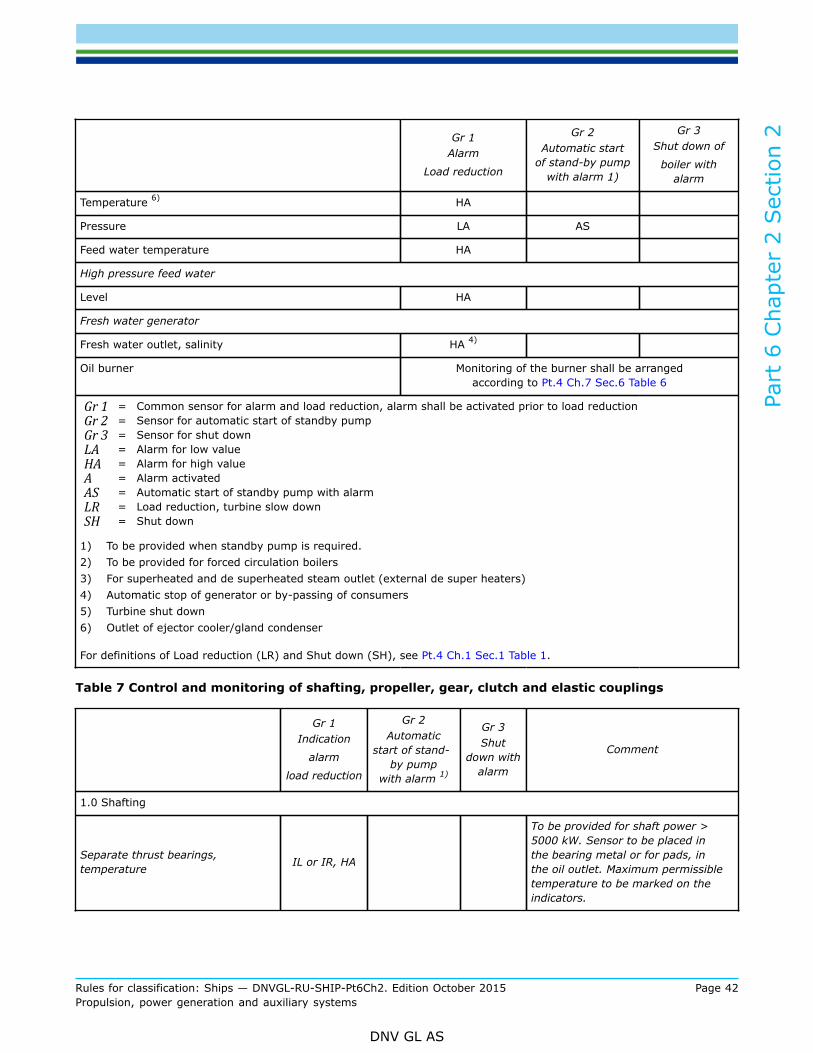
Part
6 C
hapt
er 2
Sec
tion
2
Rules for classification: Ships — DNVGL-RU-SHIP-Pt6Ch2. Edition October 2015 Page 42Propulsion, power generation and auxiliary systems
DNV GL AS
Gr 1Alarm
Load reduction
Gr 2Automatic start
of stand-by pumpwith alarm 1)
Gr 3Shut down of
boiler withalarm
Temperature 6) HA
Pressure LA AS
Feed water temperature HA
High pressure feed water
Level HA
Fresh water generator
Fresh water outlet, salinity HA 4)
Oil burner Monitoring of the burner shall be arrangedaccording to Pt.4 Ch.7 Sec.6 Table 6
Gr 1 = Common sensor for alarm and load reduction, alarm shall be activated prior to load reductionGr 2 = Sensor for automatic start of standby pumpGr 3 = Sensor for shut downLA = Alarm for low valueHA = Alarm for high valueA = Alarm activatedAS = Automatic start of standby pump with alarmLR = Load reduction, turbine slow downSH = Shut down
1) To be provided when standby pump is required.2) To be provided for forced circulation boilers3) For superheated and de superheated steam outlet (external de super heaters)4) Automatic stop of generator or by-passing of consumers5) Turbine shut down6) Outlet of ejector cooler/gland condenser
For definitions of Load reduction (LR) and Shut down (SH), see Pt.4 Ch.1 Sec.1 Table 1.
Table 7 Control and monitoring of shafting, propeller, gear, clutch and elastic couplings
Gr 1Indication
alarm
load reduction
Gr 2Automatic
start of stand-by pump
with alarm 1)
Gr 3Shut
down withalarm
Comment
1.0 Shafting
Separate thrust bearings,temperature IL or IR, HA
To be provided for shaft power >5000 kW. Sensor to be placed inthe bearing metal or for pads, inthe oil outlet. Maximum permissibletemperature to be marked on theindicators.

Part
6 C
hapt
er 2
Sec
tion
2
Rules for classification: Ships — DNVGL-RU-SHIP-Pt6Ch2. Edition October 2015 Page 43Propulsion, power generation and auxiliary systems
DNV GL AS
Gr 1Indication
alarm
load reduction
Gr 2Automatic
start of stand-by pump
with alarm 1)
Gr 3Shut
down withalarm
Comment
Oil lubricated fluid film bearings,temperature IL or IR, HA
To be provided for shaft power >5000 kW.Sensors to be located nearthe bearing surface at the area ofhighest load.Maximum permissibletemperature to be marked on theindicators.
Stern tube lubricating oil tank, level LA
Stern tube lubricating oil, pressureor flow LA Applicable to forced lubrication.
2.0 Additional requirements for TMON
Aft stern tube bearing, temperature HA
3.0 Servo oil for CP-propeller
Pressure IL, IR, LA AS The indicators shall be able to showsudden peaks in servo pressure.
Level IL, LA
Differential pressure over filter HA
4.0 Gear bearing and lubricating oil
Oil lubricated fluid film bearings(axial and radial) temperature IR, HA Applicable for gears with a total
transmitted power of 5 MW or more.
Thrust bearing, temperature IR, HA, LR
Applicable for gears with a totaltransmitted power of 5 MW or more.Sensor to be placed in the bearingmetal or for pads in the oil outlet.
Lubricating oil, pressure IL, IR, LA AS SH At bearings and spray if applicable.Shut down or clutch disengagement.
Differential pressure over filter IL, HA Alarm in case of clogged filter
Lubricating oil, temperature IL or IR, HA At inlet to bearings, i.e. after cooler.
Lubricating oil, temperature IL or IR In sump, or before cooler
Sump level 2) IL or IR For splash lubricated gears.
5.0 Integrated clutch activating media
Hydraulic oil pressure IL, IR, LA, LR AS SH SH means either declutching orengine stop
6.0 Twist of elastic couplings
Angular twist amplitudes IR, HA SH
Mean twist angle IR, HA
Applicable when failure of the elasticelement leads to loss of torquetransmission. 3)

Part
6 C
hapt
er 2
Sec
tion
2
Rules for classification: Ships — DNVGL-RU-SHIP-Pt6Ch2. Edition October 2015 Page 44Propulsion, power generation and auxiliary systems
DNV GL AS
Gr 1Indication
alarm
load reduction
Gr 2Automatic
start of stand-by pump
with alarm 1)
Gr 3Shut
down withalarm
Comment
Gr 1 = Common sensor for indication, alarm, load reduction (common sensor permitted but with different set pointsand alarm shall be activated before any load reduction)
Gr 2 = Sensor for automatic start of standby pumpGr 3 = Sensor for shut down.IL = Local indication (presentation of values), in vicinity of the monitored componentIR = Remote indication (presentation of values), in engine control room or another centralized control station such
as the local platform/manoeuvring consoleA = Alarm activated for logical valueLA = Alarm for low valueHA = Alarm for high valueAS = Automatic start of standby pump with corresponding alarmLR = Load reduction, either manual or automatic, with corresponding alarm, either slow down (r.p.m. reduction) or
alternative means of load reduction (e. g. pitch reduction), whichever is relevant.SH = Shut down with corresponding alarm. May be manually (request for shut down) or automatically executed if
not explicitly stated above.
For definitions of Load reduction (LR) and Shut down (SH), see Pt.4 Ch.1.
1) To be provided when standby pump is required.2) For gears with totally transmitted power of 500 kW or less, dipstick inspection is considered adequate.3) May be omitted if the vessel is equipped with a “take me home” device, e.g. a electric motor connected to the
gearbox (so-called PTH or PTI). Exemption may also be accepted for couplings that are of a design that enables thefull torque to be transmitted in the event of failure of the elastic elements. Such emergency claw devices are not“getting home” devices, but only meant for temporary emergency in order to prevent loss of manoeuvrability inharbours, rivers, etc
Italic text in table is equivalent to Pt.4 Ch.4
Table 8 Control and monitoring of auxiliary engines
System Item
Gr 1Indication
alarm
loadreduction
Gr 2Automatic
start ofstand-by
pump withalarm 1)
Gr 3Shut downwith alarm
Comment
Leakage from jacketedhigh pressure pipes A Level monitoring of leakage
tank or equivalent
Fuel oil pressure LA AS
High/Low temperature orviscosity of heavy fuel oil A
When fuel oil treatmentsystem is provided
1.0 Fuel oilsystem
Common rail fuel oilpressure LA

Part
6 C
hapt
er 2
Sec
tion
2
Rules for classification: Ships — DNVGL-RU-SHIP-Pt6Ch2. Edition October 2015 Page 45Propulsion, power generation and auxiliary systems
DNV GL AS
System Item
Gr 1Indication
alarm
loadreduction
Gr 2Automatic
start ofstand-by
pump withalarm 1)
Gr 3Shut downwith alarm
Comment
Lubrication oil to mainbearings, inlet pressure
IR or IL, LA, LR
AS SH
Automatic shut down forelectric power generatingenginesLR is accepted as alternativeto SH for auxiliary enginesother than driving generators
Lubrication oil tomain bearings, inlettemperature
IR or IL, HA
2.0 Lubricating oilsystem
Common rail servo oilpressure LA
3.0 Turbochargersystem Speed of turbocharger IR or IL, HA
Applicable only when theT/C is served by group ofcylinders > 1000 kW
Cylinder cooling inletpressure or flow IR or IL, LA AS
Monitoring of expansion tanklevel, with alarm at low level,is an acceptable alternativefor engines with cylinderpower < 130 kW4.0 Cylinder
coolingmedium
Cylinder cooling outlettemperature
IR or IL,HA, LR SH
Automatic shut down forelectric power generatingenginesLR is accepted as alternativeto SH for auxiliary enginesother than driving generators
5.0 Starting airsystem Start air pressure LA
Exhaust gas temp aftereach cylinder 2)
IR orIL, HA,
LR 3)
SH may replace LR forelectric power generatingengines
6.0 Exhaust gassystem
Exhaust gas temp beforeT/C 4) 5)
IR or IL,HA, LR
The LR is only required whenthe T/C is served by groupof cylinders > 2500 kW. SHmay replace LR for electricpower generating engines
7.0 Hydraulic oilsystem
Leakage from jacketedhigh pressure pipes forhydraulic operation ofvalves
A Level monitoring of leakagetank or equivalent

Part
6 C
hapt
er 2
Sec
tion
2
Rules for classification: Ships — DNVGL-RU-SHIP-Pt6Ch2. Edition October 2015 Page 46Propulsion, power generation and auxiliary systems
DNV GL AS
System Item
Gr 1Indication
alarm
loadreduction
Gr 2Automatic
start ofstand-by
pump withalarm 1)
Gr 3Shut downwith alarm
Comment
Engine speed IR
For engines other than forelectric power generation,local indication is anacceptable alternative
8.0/9.0 enginespeed/direction ofrotation
Over speed protection SH
Oil mist detection 8) HA SH
One oil mist detector havingtwo independent outputs fordetecting alarm and shut-down is acceptable.
10.0 Crankcaseexplosivecondition 6)7)
Other systems than oilmist detection LR SH
LR is accepted as alternativeto SH for auxiliary enginesother than driving generators
11. Misfire9) Detection of misfire A, LR SH10)

Part
6 C
hapt
er 2
Sec
tion
2
Rules for classification: Ships — DNVGL-RU-SHIP-Pt6Ch2. Edition October 2015 Page 47Propulsion, power generation and auxiliary systems
DNV GL AS
System Item
Gr 1Indication
alarm
loadreduction
Gr 2Automatic
start ofstand-by
pump withalarm 1)
Gr 3Shut downwith alarm
Comment
Gr 1 = Sensor(s) for indication, alarm, load reduction (common sensor permitted but with different set points andalarm shall be activated before any load reduction)
Gr 2 = Sensor for automatic start of standby pumpGr 3 = Sensor for shut down.IL = Local indication (presentation of values), in vicinity of the monitored engine component or systemIR = Remote indication (presentation of values), in engine control room or another centralized control station such
as the local platform/manoeuvring consoleA = Alarm activated for logical valueLA = Alarm for low valueHA = Alarm for high valueAS = Automatic start of standby pump with corresponding alarmLR = Load reduction, either manual or automatic, with corresponding alarmSH = Automatic shut down with corresponding alarm.
For definitions of Load reduction (LR) and Shut down (SH), see Pt.4 Ch.1.
1) To be provided when stand-by pump is required.2) Individual exhaust temperature when cylinder power > 130 kW.3) Alarm with request for load reduction to be given in case of excessive average exhaust gas temperature. This
applies when there is no separate sensor before T/C, and the T/C is served by a group of cylinders > 1000 kW. Thealarm level shall be set with due considerations to safe operation of T/C.
4) Applicable only when the T/C is served by a group of cylinders > 1000 kW and if no individual exhaust gastemperature for each cylinder. The alarm level shall be set with due considerations to safe operation of T/C.
5) Temperature measurement after turbine is accepted for T/C served by a group of cylinders < 2500 kW, providedthat the alarm levels are set to safeguard the T/C. The alarm level shall be substantiated by the T/C manufacturer.
6) Either a) 'Oil mist concentration' or b) 'Temperature monitoring of main- and crank bearings combined with crankcase pressure monitoring'. Other methods, like e.g. ´crank case pressure monitoring´ combined with either'Oil splash temperature deviation' or 'Metal particle detection' (shunt to filter), may be approved provided theircapability with regard to risk of false alarms and speed of detection is proven.
7) Applicable to engines of 2250 kW and above, or with cylinder diameter > 300 mm.8) Oil mist detectors shall be type tested in accordance with IACS UR M67.9) Example: Exhaust gas temp after each cylinder, deviation from average10) One device detecting alarm and shut-down is acceptable. Failure of the device shall be monitored and alarmed.
Italic text in table is equivalent to Pt.4 Ch.3 Sec.1 Table 11
Table 9 Control and monitoring of auxiliary turbines
System ItemGr 1
Indication
Alarm
Gr 2Automatic start
of stand-bypump with alarm
Gr 3Shut downwith alarm
Comment
Inlet pressure (afterfilter) IR or IL, LA SH1.0 Lubricating
oilInlet temperature IR, HA

Part
6 C
hapt
er 2
Sec
tion
2
Rules for classification: Ships — DNVGL-RU-SHIP-Pt6Ch2. Edition October 2015 Page 48Propulsion, power generation and auxiliary systems
DNV GL AS
System ItemGr 1
Indication
Alarm
Gr 2Automatic start
of stand-bypump with alarm
Gr 3Shut downwith alarm
Comment
Level in system tank LA
2.0 Turbinespeed Overspeed SH
SH, if applicable, to beactivated automatically,see Pt.4 Ch.3 Sec.3 [5.2]
Pressure IR, HA, SH3.0 Condensersystem Level HA AS If vacuum condenser.
4.0 Steam inlet Pressure IR or IL, LA1)
5.0 Rotor Axial displacement IR, HA SH When driving electricgenerator.
Gr 1 = Sensor(s) for indication and alarmGr 2 = Sensor for automatic start of standby pumpGr 3 = Sensor for shut downIL = Local indication − (presentation of values) in vicinity of the monitored componentIR = Remote indication − (presentation of values) in engine control room or another centralized control station
such as the local platform/manoeuvring consoleA = Alarm activated for logical valueLA = Alarm for low valueHA = Alarm for high valueAS = Automatic start of standby pump with corresponding alarmSH = Shut down with corresponding alarm.
For definitions of Load reduction (LR) and Shut down (SH), see Pt.4 Ch.1.
1) Only for turbines driving generators, may be omitted if LA for boiler steam pressure is provided.
Italic text in table is equivalent to Pt.4 Ch.3 Sec.3 Table 7
Table 10 Control and monitoring of auxiliary boiler
Alarm
1.0 Condenser
Condenser pressure HA
Note: In addition to the monitoring requirements in Pt.4 Ch.7 Sec.6 Table 2 andPt.4 Ch.7 Sec.6 Table 6,auxiliary boilers shall be provided with monitoring according to Table 10 above.
Table 11 Control and monitoring for electrical power plant
Gr 1
Alarm
1.0 Generator
Lubricating oil, pressure 1) LA

Part
6 C
hapt
er 2
Sec
tion
2
Rules for classification: Ships — DNVGL-RU-SHIP-Pt6Ch2. Edition October 2015 Page 49Propulsion, power generation and auxiliary systems
DNV GL AS
Gr 1
Alarm
Voltage LA, HA
Frequency LA
Disconnection of nonessential consumers A
Gr1 = Sensor for alarmLA = Alarm for low valueHA = Alarm for high valueA = Alarm activated
1) To be provided if separate system.
Table 12 Monitoring of miscellaneous objects
Item Alarm Comments
Bilges and bilge wells
Level, engine room, high x
2 independent alarm circuits.Minimum 2 detectors.
Purifiers
Temperature, oil inlet, high x
Temperature, oil inlet, low x
Waterseal, loss x
For heavy fuel oil.
Soot-blowers, sequence stopped x
Automatic control system, power failure x
Alarm and safety system, power failure x
Remote control system, power failure x
Fire alarm systems, failure x
Electric, pneumatic, hydraulic.
Table 13 Monitoring of tanks
Item Alarm Comments
Sludge and drain tanks, level, high x
Service tanks, level, low x
Expansion tanks, level, low x
Circulating tanks, level, low x
Fuel oil drain collecting tank, level, high x
When automatic pumping up of tanks isarranged, alarm shall be released if the levelexceeds safe level.
Part
6 C
hapt
er 2
Sec
tion
2
Rules for classification: Ships — DNVGL-RU-SHIP-Pt6Ch2. Edition October 2015 Page 50Propulsion, power generation and auxiliary systems
DNV GL AS
3.2 Arrangement on the bridge3.2.1 General
3.2.1.1 Individual alarms are required for:
— automatic shutdown of main boiler— automatic shutdown and/or slowdown of propulsion machinery— request for manual shutdown and/or slowdown of propulsion machinery— power failure bridge alarm system— failure in the remote control systems with respect to propulsion machinery, including controllable pitch
propeller if arranged— failure in the remote control systems with respect to steering— low starting air pressure for reversible propulsion engines.
3.2.1.2 The propulsion plant shall be restarted after a blackout, either manually from the navigation bridge orautomatically. When manual starting from the navigation bridge is arranged, an indication shall be providedwhen the propulsion can be restarted, i.e., when all systems are in normal operating condition.The starting arrangement shall be simple to operate.
Guidance note:Steam propulsion plants are exempted from these requirements.
---e-n-d---of---g-u-i-d-a-n-c-e---n-o-t-e---
3.2.1.3 Resetting of the propulsion machinery safety system shall be arranged when it is activated at blackout. The reset action may either be automatic, or manually activated from the bridge, e.g. by bringing themanoeuvring lever to stop position. The reset shall only be possible when all the applicable parameters are innormal condition.
3.3 Arrangement in the engine room3.3.1 General
3.3.1.1 Indicating instruments, alarm displays and manoeuvring devices shall be centralised in a convenientposition, in or adjacent to the engine room.
Guidance note:The layout of instruments in the control desk should comply with generally accepted ergonomical principles. Red lamps should beused only as alarm lamps.
---e-n-d---of---g-u-i-d-a-n-c-e---n-o-t-e---
3.4 Control of propulsion machinery from the navigation bridge (SOLAS Ch.II-1/49)3.4.1 General
3.4.1.1 In addition to the general requirements in Pt.4 Ch.1 the following shall be complied with.
3.4.1.2 Under all sailing conditions, including manoeuvring, the speed, direction of thrust and, if applicablethe pitch of the propeller shall be fully controllable from the navigation bridge.

Part
6 C
hapt
er 2
Sec
tion
2
Rules for classification: Ships — DNVGL-RU-SHIP-Pt6Ch2. Edition October 2015 Page 51Propulsion, power generation and auxiliary systems
DNV GL AS
3.4.1.3 Such remote control shall be performed by a single control device for each independent propeller,with automatic performance of all associated services, including where necessary, means of preventingoverload of the propulsion machinery.
3.4.1.4 The main propulsion machinery shall be provided with an emergency stopping device on thenavigation bridge independent of the navigation bridge control system.
3.4.1.5 Propulsion machinery orders from the navigation bridge shall be indicated in the main machinerycontrol room or at the propulsion machinery control position as appropriate.
3.4.1.6 Remote control of the propulsion machinery shall be possible only from one location at a time; atsuch locations interconnected control positions are permitted. At each location there shall be an indicatorshowing which location is in control of the propulsion machinery. The transfer of control between thenavigation bridge and machinery space shall be possible only in the main machinery space or in the mainmachinery control room. The system shall include means to prevent the propelling thrust from alteringsignificantly when transferring control from one location to another.
3.4.1.7 It shall be possible for all machinery essential for the safe operation of the ship to be controlled froma local position, even in the case of failure in any part of the automatic or remote control systems.
3.4.1.8 The design of the remote automatic control system shall be such that in case of its failure an alarmwill be given, and the present speed and direction of thrust of the propeller is maintained until local control isin operation.
3.4.1.9 Indicators shall be fitted on the navigation bridge for:
a) propeller speed and direction of rotation in the case of fixed pitch propellers, orb) propeller speed and pitch position in the case of controllable pitch propellers.
3.4.1.10 The number of consecutive automatic attempts which fail to produce a start shall be limited tosafeguard sufficient starting air pressure. An alarm shall be provided indicating low starting air pressure setat a level which still permits starting operations of the propulsion machinery.
Guidance note:Air should be understood as any stored energy.
---e-n-d---of---g-u-i-d-a-n-c-e---n-o-t-e---
3.5 Electric power supply3.5.1 General
3.5.1.1 Arrangements shall be provided to prevent overloading of the generating sets.Guidance note:A generating set consists of one electrical generator and its prime mover.
---e-n-d---of---g-u-i-d-a-n-c-e---n-o-t-e---
3.5.1.2 Standby generating sets shall to have separate cooling water and lubricating oil pumps. Alternatively,automatic start of standby pumps shall be arranged when they also serve other generating sets.
3.5.2 Secondary distribution systems
3.5.2.1 For essential consumers with power supply from secondary distribution systems, precautions againstpower failure shall be similar to those taken for units having power supply from the main system. E.g., thefollowing means may be applied:

Part
6 C
hapt
er 2
Sec
tion
2
Rules for classification: Ships — DNVGL-RU-SHIP-Pt6Ch2. Edition October 2015 Page 52Propulsion, power generation and auxiliary systems
DNV GL AS
— adequate automatic emergency lighting for access to standby transformer for the lighting system andoperating gear for manual connection
— automatic connection of standby transformer— parallel connection of a sufficient number of transformers and arrangement for selective disconnection— automatic connection of emergency source of power— dividing the system in two or more circuits with automatic switchover.
In this context, essential consumers are units and equipment necessary for manoeuvring of the ship,including navigation lights and sufficient lighting (either as part of the normal lighting or as separateemergency lighting) in the engine room, on the bridge, in the chart room, in all passageways and stairwaysof the accommodation.
3.6 Fire safety3.6.1 General
3.6.1.1 Where the Society finds it necessary, oil fuel and lubricating oil pressure pipelines shall be shieldedor otherwise suitably protected to avoid as far as practicable oil spray or leakages on to hot surfaces or intomachinery air intakes. Fuel oil injection pipes on all engines, irrespective of cylinder bore, shall be effectivelyshielded and secured. The number of joints in such piping systems shall be kept to a minimum and, wherepracticable, leakages from high pressure oil fuel pipes shall be collected, and safe drainage to a collectingtank shall be provided (see Pt.4 Ch.3 Sec.1 Table 10 and Pt.4 Ch.3 Sec.1 Table 11).
3.7 Special requirements for ships less than 300 gross tonnage withpropulsive output less than 1000 kW per engine3.7.1 General
3.7.1.1 The requirements in [3.1], [3.2], [3.3], [3.5] and [3.6] do not apply.
3.7.2 Extent of monitoring
3.7.2.1 An alarm shall be initiated for the following conditions:
— fire in engine room— bilge level, high— power failure, alarm and remote control system— for drivers, power transmissions and driven units according to Pt.4 Ch.3, Pt.4 Ch.4 and Pt.4 Ch.5.
Main and auxiliary engines: See Pt.4 Ch.3.
3.7.3 Arrangement on the bridge and engineers’ accommodation
3.7.3.1 All alarms in the engine room shall initiate an alarm on the navigation bridge, and engineers’accommodation individual or collective.
3.7.4 Fire safety
3.7.4.1 Fuel oil injection pipes on all engines, irrespective of cylinder bore, shall be effectively shielded andclamped.
3.7.5 Fire alarm system
3.7.5.1 The ship shall have a fire alarm system that shall be initiated in the event of fire in the engine roomand or boiler room.
Part
6 C
hapt
er 2
Sec
tion
2
Rules for classification: Ships — DNVGL-RU-SHIP-Pt6Ch2. Edition October 2015 Page 53Propulsion, power generation and auxiliary systems
DNV GL AS
Guidance note:The fire detectors may be arranged as a single loop provided it is normally closed.The fire detectors loop(s) may be connected to the machinery alarm system provided separate indication on the navigation bridgeis arranged.
---e-n-d---of---g-u-i-d-a-n-c-e---n-o-t-e---
4 Class notation ECO
4.1 General requirements4.1.1 Application
4.1.1.1 This section applies to machinery operation with continuous supervision from a centralised controlstation. The control station shall provide control and monitoring devices necessary to make the machineryoperation as safe and effective as it would be under direct supervision.
4.2 Control station4.2.1 Arrangement
4.2.1.1 The arrangement shall be such that all supervision and manual operations which are necessary forsafe operation of the machinery plant can be carried out at the control station. This will imply that stoppingof machinery, starting of stand-by units etc. in case of machinery faults shall be possible from the controlstation if not automatically carried out.
4.2.1.2 The control station shall be located in the engine room or in its close proximity. The control stationmay be arranged on or adjacent to navigation bridge provided it does not interfere with the navigation bridgecontrol positions, and an additional centralised control position is arranged in or adjacent to the engine room.This control position shall permit some machinery control and monitoring facilities as required in [4.1.1].
4.3 System arrangement4.3.1 General
4.3.1.1 The requirements of [2] shall be complied with to the extent applicable.
4.3.2 Alarm system
4.3.2.1 A system of alarm displays shall be provided in the centralised control station for easy identificationof machinery faults.
4.3.2.2 An extension alarm system and a watch responsibility transfer system to the navigation bridge andthe engineers' accommodation is not required.
4.3.3 Safety system
4.3.3.1 The safety systems specified in [2.4] can be omitted with the exception of the safety functionsrequired in Pt.4. Corrective actions at machinery faults are presumed to be carried out manually.

Part
6 C
hapt
er 2
Sec
tion
2
Rules for classification: Ships — DNVGL-RU-SHIP-Pt6Ch2. Edition October 2015 Page 54Propulsion, power generation and auxiliary systems
DNV GL AS
4.3.4 Remote control system
4.3.4.1 Propulsion machinery shall be arranged for remote control from the centralised control station. Therequirements given in [2] and Pt.4 Ch.1 Sec.4 shall be complied with to the extent applicable.
4.3.5 Fire alarm system
4.3.5.1 The fire alarm system shall satisfy the requirement of [2.5].
4.4 Extent of monitoring4.4.1 General
4.4.1.1 Monitoring of machinery shall comply with the requirements in [3] and Pt.4 Ch.3, Pt.4 Ch.4 and Pt.4Ch.5.
5 Survey
5.1 General5.1.1 Trials
5.1.1.1 Upon completion of the installation, trials shall be carried out alongside quay and at sea in thepresence of the surveyor for E0 and ECO notations. The test in [5.1.8] for the extension alarm system is notapplicable for the ECO notation.
5.1.1.2 The sea trials should be reserved solely for testing of the automatic and the remote control systems,and the fire alarm system. Other tests should be completed alongside quay.
5.1.1.3 The sea trials shall include a four hours continuous operation with unattended machinery spaces.Agreement shall be made in advance in each case for personnel that will be present in the control room.
Guidance note:The four hour test may be combined with the endurance test of the engines.Personnel for ordinary upkeep and control of the machinery are not to be present in the engine room. Special measurements canbe carried out according to agreement, e.g. noise measurements.
---e-n-d---of---g-u-i-d-a-n-c-e---n-o-t-e---
5.1.1.4 A detailed test programme, including expected test results, shall be prepared and submitted forapproval prior to the trials. The programme shall be kept on board, all filled in and signed by the surveyorupon completion of the trials.
5.1.1.5 Recording of important automatically controlled parameters may be required as part of the testing.
5.1.2 Monitoring system
5.1.2.1 Alarms and safety actions as required by these rules shall be tested. Failure conditions shall besimulated as realistically as possible, preferably by letting the monitored parameters exceed the alarm andsafety limits.

Part
6 C
hapt
er 2
Sec
tion
2
Rules for classification: Ships — DNVGL-RU-SHIP-Pt6Ch2. Edition October 2015 Page 55Propulsion, power generation and auxiliary systems
DNV GL AS
5.1.3 Black out recovery
5.1.3.1 It shall be tested that, after a black-out and subsequent automatic restoration of power, thepropulsion and steering function can be restored from the bridge without manual intervention in the engineroom.
5.1.4 Fire detection- and alarm system
5.1.4.1 After installation, the fire detection and fire alarm system shall be tested under varying conditions ofengine operation and ventilation.(SOLAS Ch. II-2/14.3).
Guidance note:The test should be performed with all machinery and ventilation running in normal sea going conditions during the sea trial by meansof smoke released in positions of high fire risk.
---e-n-d---of---g-u-i-d-a-n-c-e---n-o-t-e---
5.1.5 Remote propulsion control systems
5.1.5.1 Testing of the remote control system for the propulsion machinery shall be carried out at sea. Prior totesting, the propulsion machinery shall run for at least 1 hour.
5.1.5.2 All tests included in the test programme for the remote control system shall be carried out withoutmanual assistance from the engine room, and all systems shall be in operation as normal for unattendedmachinery space.
5.1.5.3 The remote control system shall be tested at sea to demonstrate stable control and operation of thepropulsion system with its necessary auxiliaries over the full operating range, and regardless of the type ofpropulsion. It shall be demonstrated that necessary ramping / controller functions are implemented to ensurethat any operation of the manoeuvring levers do not cause shutdown, instability or damage to the propulsionmachinery or power generating units.The different tests described below may be seen as the expected functional test scope for certain propulsionremote control systems, but other equivalent tests may be more appropriate depending on the actualinstallation on board.
Guidance note:
1) Ships with fixed pitch propeller
a) The test programme should as a minimum include the following manoeuvres:
i) from stop to dead slow ahead. Proceed stepwise to full ahead. Before each step increase, the r.p.m. of theprevious setting shall have reached its steady state condition
ii) from approximately 2/3 of full speed ahead, go quickly to slow astern. Proceed stepwise to full astern
iii) stop
iv) after approximately 5 minutes stop, start ahead
v) when the ship has reached approximately 2/3 of full speed ahead, go quickly to half astern
vi) when the ship has reached approximately 2/3 of full speed ahead, go quickly to dead slow ahead
vii) when the r.p.m. is nearly stabilized, go quickly to full ahead
viii) when the ship has reached approximately half speed ahead, go to stop and back to dead slow ahead within 1second.
b) With air compressors stopped, make 12 starts with the remote control system, alternating between ahead and astern.This applies to reversible engines using starting air for re-start.
c) Testing of possible automatic restarts. Go to ahead and let the engine repeat the predetermined starting at tempts. Goto stop. Return to ahead and check that an additional starting attempt is affected. This applies to diesel engines only.

Part
6 C
hapt
er 2
Sec
tion
2
Rules for classification: Ships — DNVGL-RU-SHIP-Pt6Ch2. Edition October 2015 Page 56Propulsion, power generation and auxiliary systems
DNV GL AS
d) Simulate failures causing automatic load reduction or stop of the engine. Cancel if possible this safety action and showthat the engine is again controllable from the bridge.
e) During bridge control at half speed ahead, cut out power supply to the remote control system. No immediate criticalsituation shall arise. Switch over to standby manual control in the engine room, and show that this control systemfunctions satisfactorily.
f) At approximately 2/3 of full speed ahead, test the emergency stop system.
2) Ships with controllable pitch propeller
a) The tests specified below apply to remote control systems with a single manoeuvring lever on the bridge. For plantswith dual lever control, one for r.p.m. and one for pitch, the tests to be carried out will be considered in each case.
i) start the engine, from the bridge if possible, and go to dead slow ahead. Proceed stepwise to full ahead. Beforeeach step increase, the r.p.m. of the previous setting shall have reached its steady state condition
ii) from approximately 2/3 of full speed ahead, go quickly to dead slow astern. Proceed stepwise to full astern
iii) go to neutral position
iv) after approximately 5 minutes in neutral position, go to ahead
v) when the ship has reached approximately 2/3 of full speed ahead, go quickly to 2/3 of full astern
vi) when the ship is «dead in the water», go quickly to half ahead.
b) Simulate failures causing automatic load reduction or stop of the engine. Cancel if possible this safety action and showthat the engine is again controllable from the bridge.
c) During bridge control at half speed ahead, cut out power supply to the remote control system. No immediate criticalsituation shall arise. Switch over to standby manual control in the engine room, and show that this control systemfunctions satisfactorily.
d) At approximately 2/3 of full speed ahead, test the emergency stop system
3) Steam turbine ships
a) The test programme should as a minimum include:
i) from stop to dead slow ahead. Proceed stepwise to full ahead. Before each step increase, the r.p.m. of theprevious setting shall have reached its steady state condition
ii) from full speed ahead, reduce stepwise to stop with the same intervals
iii) from stop, increase stepwise to full astern. Run until the ship has reached a fair speed astern
iv) from full astern, reduce stepwise to stop
v) show that the automatic turning arrangement operates satisfactorily during the stop period. Go to full ahead
vi) after approximately 10 minutes full ahead, go quickly to stop
vii) after approximately 5 minutes stop, go quickly to 2/3 of full astern
viii) when the ship is «dead in the water», go quickly to full ahead
ix) when the ship has reached approximately 2/3 of full speed ahead, go quickly to 2/3 of full astern and run until theship is «dead in the water»
x) go to full ahead. When the ship has reached approximately 2/3 of full speed ahead, go to stop and back to deadslow ahead within 1 second. Transfer control to the engine room.
b) Repeat the first four manoeuvres using the manoeuvring system in the engine room. Transfer control to the bridge.
c) During bridge control at half speed ahead, cut out power supply to the remote control system. No immediate criticalsituation shall arise. Switch over to standby manual control in the engine room, and show that this control systemfunctions satisfactorily.
d) Simulate failures causing automatic load reduction or stop of turbines. Cancel, if possible, this safety action and showthat the turbines are again controllable from the bridge.
e) At approximately 2/3 of full speed ahead, test the emergency stop system.
---e-n-d---of---g-u-i-d-a-n-c-e---n-o-t-e---

Part
6 C
hapt
er 2
Sec
tion
2
Rules for classification: Ships — DNVGL-RU-SHIP-Pt6Ch2. Edition October 2015 Page 57Propulsion, power generation and auxiliary systems
DNV GL AS
5.1.6 Main alarm system
5.1.6.1 All functions of the main alarm system shall be tested.
5.1.7 Watch responsibility transfer system
5.1.7.1 All functions of the watch responsibility transfer system shall be tested
5.1.8 Extension alarm system
5.1.8.1 For E0 notation, all functions of the extension alarm system shall be tested
Part
6 C
hapt
er 2
Sec
tion
3
Rules for classification: Ships — DNVGL-RU-SHIP-Pt6Ch2. Edition October 2015 Page 58Propulsion, power generation and auxiliary systems
DNV GL AS
SECTION 3 FUEL CELL INSTALLATIONS - FC
1 General
1.1 IntroductionThe additional class notations FC(Power) and FC(Safety) apply to fuel cell installations on-board ships,thus contributing to a global reduction in known air pollutants, whilst adding support to environmentalspecific pollution reduction methods such as hydrodynamic, wind and geothermal. Fuel cells do not need anenvironment specific location to work well, are highly efficient, and produce much less harmful air pollutants.Typical fuels that may be relevant are natural gas, methanol, propane, hydrogen or diesel fuels. Bio- fuelswill be subject to special consideration. In this section, only the gaseous fuels as well as liquid fuels withflashpoint below 60 degrees C are regarded as "FC fuel". Liquid fuels with flashpoint above 60 degrees shouldfollow requirements for normal fuel in Pt.4 Ch.6.
1.2 ScopeThe scope of additional class notations FC(Power) and FC(Safety) is to add an additional level of safety,related to air pollutants. These rules are applicable for installations with a variety of gaseous and liquid fuels,such as natural gas and diesel fuels, respectively. Since the fuel cell technology is still under development,the requirements of this section may have to be supported by alternative additional requirements, consideredon case by case basis. See Pt.4 Ch.1 Sec.1 [1.1.3]. Survey requirements for ships with class notationFC(Power) and FC(Safety) can be found in Pt.7 Ch.1 Sec.2 and Pt.7 Ch.1 Sec.3.
1.3 ApplicationShips that satisfy the design requirements given in this section, where the fuel cell power is used foressential, important or emergency services, may be assigned the additional class notation FC(Power).Ships that satisfy the design requirements given in this section, where the fuel cell power is not usedfor essential, important or emergency services, shall satisfy the safety and environmental requirements.Installations complying with the requirements in this section, except 3.2 may be assigned class notationFC(Safety).
1.4 Classification1.4.1 Class notation
1.4.1.1 Ships where the fuel cell power is used for essential, important or emergency services shall satisfythe requirements in this rule section and will be given class notation FC(Power).
1.4.1.2 Ships where the fuel cell power is not used for essential, important or emergency services shallsatisfy the safety and environmental requirements. Installations complying with the requirements in thissection, except Sec.2 will be given class notation FC(Safety).
1.4.2 Survey extent
1.4.2.1 Survey requirements for ships with class notation FC(Power) and FC(Safety) can be found in Pt.7Ch.1 Sec.2 and Pt.7 Ch.1 Sec.3.
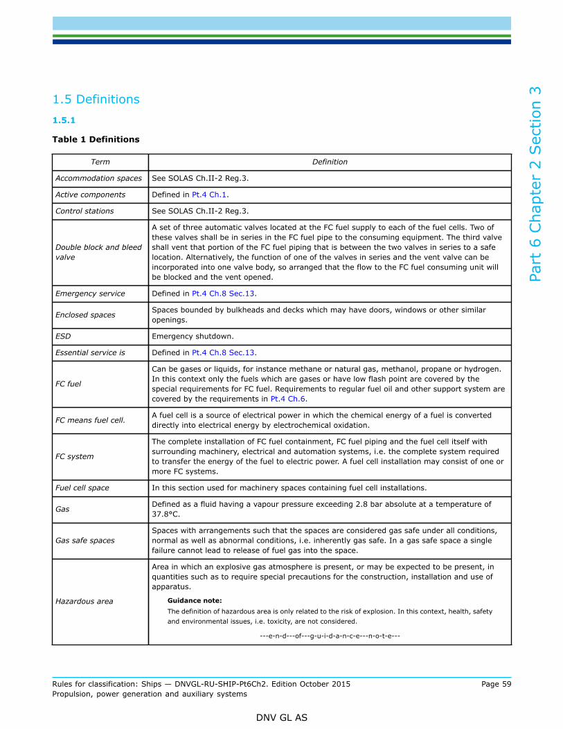
Part
6 C
hapt
er 2
Sec
tion
3
Rules for classification: Ships — DNVGL-RU-SHIP-Pt6Ch2. Edition October 2015 Page 59Propulsion, power generation and auxiliary systems
DNV GL AS
1.5 Definitions1.5.1
Table 1 Definitions
Term Definition
Accommodation spaces See SOLAS Ch.II-2 Reg.3.
Active components Defined in Pt.4 Ch.1.
Control stations See SOLAS Ch.II-2 Reg.3.
Double block and bleedvalve
A set of three automatic valves located at the FC fuel supply to each of the fuel cells. Two ofthese valves shall be in series in the FC fuel pipe to the consuming equipment. The third valveshall vent that portion of the FC fuel piping that is between the two valves in series to a safelocation. Alternatively, the function of one of the valves in series and the vent valve can beincorporated into one valve body, so arranged that the flow to the FC fuel consuming unit willbe blocked and the vent opened.
Emergency service Defined in Pt.4 Ch.8 Sec.13.
Enclosed spaces Spaces bounded by bulkheads and decks which may have doors, windows or other similaropenings.
ESD Emergency shutdown.
Essential service is Defined in Pt.4 Ch.8 Sec.13.
FC fuel
Can be gases or liquids, for instance methane or natural gas, methanol, propane or hydrogen.In this context only the fuels which are gases or have low flash point are covered by thespecial requirements for FC fuel. Requirements to regular fuel oil and other support system arecovered by the requirements in Pt.4 Ch.6.
FC means fuel cell. A fuel cell is a source of electrical power in which the chemical energy of a fuel is converteddirectly into electrical energy by electrochemical oxidation.
FC system
The complete installation of FC fuel containment, FC fuel piping and the fuel cell itself withsurrounding machinery, electrical and automation systems, i.e. the complete system requiredto transfer the energy of the fuel to electric power. A fuel cell installation may consist of one ormore FC systems.
Fuel cell space In this section used for machinery spaces containing fuel cell installations.
Gas Defined as a fluid having a vapour pressure exceeding 2.8 bar absolute at a temperature of37.8°C.
Gas safe spacesSpaces with arrangements such that the spaces are considered gas safe under all conditions,normal as well as abnormal conditions, i.e. inherently gas safe. In a gas safe space a singlefailure cannot lead to release of fuel gas into the space.
Hazardous area
Area in which an explosive gas atmosphere is present, or may be expected to be present, inquantities such as to require special precautions for the construction, installation and use ofapparatus.
Guidance note:The definition of hazardous area is only related to the risk of explosion. In this context, health, safetyand environmental issues, i.e. toxicity, are not considered.
---e-n-d---of---g-u-i-d-a-n-c-e---n-o-t-e---

Part
6 C
hapt
er 2
Sec
tion
3
Rules for classification: Ships — DNVGL-RU-SHIP-Pt6Ch2. Edition October 2015 Page 60Propulsion, power generation and auxiliary systems
DNV GL AS
Term Definition
High pressure piping In this context piping with maximum working pressure above 10 bar.
Important service Defined in Pt.4 Ch.8 Sec.13.
LEL Lower explosion limit.
Low flashpoint liquids Liquids with a flashpoint below 60°C.
Main tank valve A remote operated valve on the FC fuel outlet from a FC fuel storage tank, located as close tothe tank outlet point as possible.
Master fuel valve An automatic valve in the FC fuel supply line to each fuel cell located outside the FC space andas close to the fuel storage as possible.
Non-hazardous area Area in which an explosive gas atmosphere is not expected to be present in quantities such asto require special precautions for the construction, installation and use of apparatus
Safe location
Location on open deck remote from any source of ignition were flammable gas, vapour or liquidcan be released to the atmosphere and are expected to be diluted by natural ventilation. Safelocations shall be arranged in such a manner that released flammable gas, vapour or liquid arenot ventilated in other areas were potential sources of ignitions are present.
Semi-enclosed spacesLocations where natural conditions of ventilation are notably different from those on opendecks due to the presence of structures such as roofs, wind breakers and bulkheads and whichare so arranged that dispersion of gas may not occur.
Service spacesSpaces outside the cargo area used for galleys, pantries containing cooking appliances, lockers,mail and specie rooms, store rooms, workshops other than those forming part of the machineryspaces and similar spaces and trunks to such spaces.
Sources of release Valves or detachable pipe joints in the FC fuel system. Also compressors and seals of pumps inthe FC fuel system are regarded as sources of release.
Zones Hazardous areas are classified into zones based upon the frequency of the occurrence andduration of an explosive gas atmosphere, as follows:
Zone 0Place in which an explosive atmosphere consisting of a mixture with air of flammablesubstances in the form of gas, vapour or mist is present continuously or for long periods orfrequently.
Zone 1 Place in which an explosive atmosphere consisting of a mixture with air of flammablesubstances in the form of gas, vapour or mist is likely to occur in normal operation occasionally.
Zone 2Place in which an explosive atmosphere consisting of a mixture with air of flammablesubstances in the form of gas, vapour or mist is not likely to occur in normal operation but, if itdoes occur, will persist for a short period only.
1.6 Documentation1.6.1 Plans and particulars
1.6.1.1 Special components, equipment or systems not covered in the different parts of the existing rulesmay be required to be documented. Documentation requirements for such components and equipment willbe subject to special consideration.
1.6.1.2 Documentation shall be submitted as required by Table 2.

Part
6 C
hapt
er 2
Sec
tion
3
Rules for classification: Ships — DNVGL-RU-SHIP-Pt6Ch2. Edition October 2015 Page 61Propulsion, power generation and auxiliary systems
DNV GL AS
Table 2 Documentation requirements for class notation FC(Power) and FC(Safety)
Object Documentation type Additional description Info
Z030 – Arrangement plan
Giving location of:
— machinery and boiler spaces, accommodation,service and control station spaces
— FC fuel tanks and FC fuel containment systems— FC fuel pump and compressor rooms— FC fuel piping with shore connections— tank hatches, ventilation pipes and any other
openings to the FC fuel tanks— ventilating pipes, doors and openings to FC
fuel pump rooms, compressor rooms and otherhazardous areas
— entrances, air inlets and openings toaccommodation, service and control station spaces
— purge lines and safety blow-off lines of gaseousfuels
FI
G080 – Hazardous areaclassification drawing AP
H030 - Tank and capacity plan Including FC fuel containment systems. AP
S010 – Piping diagram (PD) FC fuel, including shore connections AP
G060 - Structural fire protectiondrawing AP
Z072 – Safety description
The safety aspects in this connection are for instanceexplosion hazards, fire effects from the fuel cell itselfor from the fuel cell support systems. If a fuel cell isconnected to the grid any potential hazards affectingthe ship’s total power system should be included
AP
Fuel cellinstallation
Z030 – Arrangement planarrangement drawings of the fuel cell includingdimensions, materials, operating temperatures,pressures, weights
FI
Fuel cell Z060 – Functional description
including
— fuel cell principles— specification of FC module outer surface
temperature.— voltage and current levels in different parts of the
cell type of fuels— maintenance plan (replacement of stack etc.)
earthing principles— short circuit contribution capability— documentation of life time and availability, e.g.
deterioration rate curve or similar.
FI

Part
6 C
hapt
er 2
Sec
tion
3
Rules for classification: Ships — DNVGL-RU-SHIP-Pt6Ch2. Edition October 2015 Page 62Propulsion, power generation and auxiliary systems
DNV GL AS
Object Documentation type Additional description Info
Z071 – Failure mode and effectanalysis (FMEA)
A failure mode and effect analysis (FMEA) examining allpossible faults affecting the processes in the fuel cellsshall be submitted for approval, together with a testprogram for verification of the main conclusions fromthe FMEA.
— The power deterioration rate for the fuel cell shallbe documented through analysis or test results, andshall consider different power levels and differentmodes of operation.
AP
Z252 – Test procedure atmanufacturer
Z253 – Test procedure for quayand sea trial
The test programme can be based on the IEC standard62282-3-1 “Stationary fuel cell power systems- Safety”,but shall also have to take the environmental andoperating conditions in a ship into account.
AP
C010 – Design criteria
— design pressure— design temperature— volume(s)— fluid(s)— additional loads, if applicable— proposed set pressure of safety valve— pressure vessel class
FI
C020 – Assembly orarrangementdrawing Including valves and fittings. FI
C030 – Detailed drawing Including attachments and supports. AP
C040 – Design analysis AP
C050 – Non-destructivetesting(NDT) plan AP
Fuel cell -pressurecontainingcomponents
S010 – Piping diagram (PD)
Plans of the following piping systems shall be submittedfor approval:
— FC fuel piping— vent lines of safety relief valves or similar piping— cooling/ heating water system in connection with FC
fuel system if fitted— drawings and specifications of insulation where such
insulation is installed— specification of electrical bonding of piping— specification of heat tracing arrangements if fitted.
AP
S090 – Specification of piping,valves, flanges and fittings AP
Z162 - Installation manualprogram for functional tests of all piping systemsincluding valves, fittings and associated equipment forhandling FC fuel (liquid or vapour)
APFuel cell - piping
P020 – Sizing calculations for safety relief valves and pressure/vacuum reliefvalves AP

Part
6 C
hapt
er 2
Sec
tion
3
Rules for classification: Ships — DNVGL-RU-SHIP-Pt6Ch2. Edition October 2015 Page 63Propulsion, power generation and auxiliary systems
DNV GL AS
Object Documentation type Additional description Info
S012 – Ducting diagram (DD)
Plans of the following equipment and systems withparticulars shall be submitted:
— arrangements and specifications of mechanicalventilation systems in spaces covering FC fuelsystems, giving capacity and location of fans andtheir motors. For fans and ventilators; drawings andmaterial specifications of rotating parts and casings
— arrangement and specifications of piping systems forgas freeing and purging of FC and piping
— for fixed gas detection and alarm systems:specification and location of detectors, alarm devicesand call points, and cable routing layout drawing
— bilge and drainage arrangements in FC module, ifapplicable
— air inlet arrangement including filters— exhaust arrangement
AP
S030 – Capacity analysis AP
C030 – Detailed drawing Rotating parts and casing of fans. APFuel Cell spaces –ventilation
I200 – Control and monitoringsystem documentation AP
Z030 – Arrangement plan Detectors, call points and alarm devices. APFuel Cell spaces –gas detection andalarm system,fixed
G060 – Structural fire protectiondrawing AP
G200 – Fixed fire extinguishingsystem documentation AP
Fuel Cell spaces -fire protection I200 – Control and monitoring
system documentation AP
Z030 – Arrangement plan Detectors, call points and alarm devices. APFuel Cell spaces –fire detection andalarm system
G080 – Hazardous areaclassification drawing
location of electric equipment in hazardous area shallbe shown with cross reference to E090 AP
E090 – Table of Ex-installation AP
Z163 - Maintenance manual for electrical installations in hazardous areas FI
E130 - Electrical datasheet,Semiconductor assemblies, A typeapproval certificatefrom the Society is accepted as an alternative to thedatasheet.
FI
Fuel Cell –electricalinstallation
E110 – Cable data sheet anddesign drawing If not type approved by the Society AP
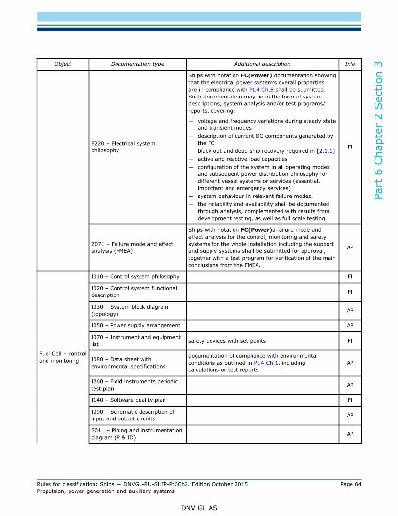
Part
6 C
hapt
er 2
Sec
tion
3
Rules for classification: Ships — DNVGL-RU-SHIP-Pt6Ch2. Edition October 2015 Page 64Propulsion, power generation and auxiliary systems
DNV GL AS
Object Documentation type Additional description Info
E220 – Electrical systemphilosophy
Ships with notation FC(Power) documentation showingthat the electrical power system’s overall propertiesare in compliance with Pt.4 Ch.8 shall be submitted.Such documentation may be in the form of systemdescriptions, system analysis and/or test programs/reports, covering:
— voltage and frequency variations during steady stateand transient modes
— description of current DC components generated bythe FC
— black out and dead ship recovery required in [2.1.1]— active and reactive load capacities— configuration of the system in all operating modes
and subsequent power distribution philosophy fordifferent vessel systems or services (essential,important and emergency services)
— system behaviour in relevant failure modes.— the reliability and availability shall be documented
through analysis, complemented with results fromdevelopment testing, as well as full scale testing.
FI
Z071 – Failure mode and effectanalysis (FMEA)
Ships with notation FC(Power)a failure mode andeffect analysis for the control, monitoring and safetysystems for the whole installation including the supportand supply systems shall be submitted for approval,together with a test program for verification of the mainconclusions from the FMEA.
AP
I010 – Control system philosophy FI
I020 – Control system functionaldescription FI
I030 – System block diagram(topology) AP
I050 – Power supply arrangement AP
I070 – Instrument and equipmentlist safety devices with set points FI
I080 – Data sheet withenvironmental specifications
documentation of compliance with environmentalconditions as outlined in Pt.4 Ch.1, includingcalculations or test reports
AP
I260 – Field instruments periodictest plan AP
I140 – Software quality plan FI
I090 – Schematic description ofinput and output circuits AP
Fuel Cell – controland monitoring
S011 – Piping and instrumentationdiagram (P & ID) AP
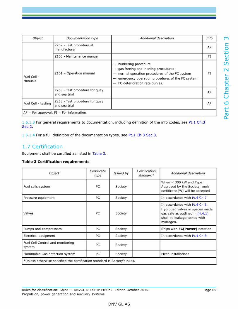
Part
6 C
hapt
er 2
Sec
tion
3
Rules for classification: Ships — DNVGL-RU-SHIP-Pt6Ch2. Edition October 2015 Page 65Propulsion, power generation and auxiliary systems
DNV GL AS
Object Documentation type Additional description Info
Z252 - Test procedure atmanufacturer AP
Z163 - Maintenance manual FI
Z161 – Operation manual
— bunkering procedure— gas freeing and inerting procedures— normal operation procedures of the FC system— emergency operation procedures of the FC system— FC deterioration rate curves.
FIFuel Cell -Manuals
Z253 - Test procedure for quayand sea trial AP
Fuel Cell - testing Z253 - Test procedure for quayand sea trial AP
AP = For approval; FI = For information
1.6.1.3 For general requirements to documentation, including definition of the info codes, see Pt.1 Ch.3Sec.2.
1.6.1.4 For a full definition of the documentation types, see Pt.1 Ch.3 Sec.3.
1.7 CertificationEquipment shall be certified as listed in Table 3.
Table 3 Certification requirements
Object Certificatetype Issued by Certification
standard* Additional description
Fuel cells system PC SocietyWhen < 300 kW and TypeApproved by the Society, workcertificate (W) will be accepted
Pressure equipment PC Society In accordance with Pt.4 Ch.7
Valves PC Society
In accordance with Pt.4 Ch.6.Hydrogen valves in spaces madegas safe as outlined in [4.4.1]shall be leakage tested withhydrogen.
Pumps and compressors PC Society Ships with FC(Power) notation
Electrical equipment PC Society In accordance with Pt.4 Ch.8.
Fuel Cell Control and monitoringsystem PC Society
Flammable Gas detection system PC Society Fixed installations
*Unless otherwise specified the certification standard is Society’s rules.
Part
6 C
hapt
er 2
Sec
tion
3
Rules for classification: Ships — DNVGL-RU-SHIP-Pt6Ch2. Edition October 2015 Page 66Propulsion, power generation and auxiliary systems
DNV GL AS
1.8 Operation and maintenance manuals1.8.1 Contents
1.8.1.1 An operation manual containing procedures as required in Table 2 shall be kept onboard.
1.8.1.2 A plan for systematic maintenance and function testing shall be kept on-board showing in detail howcomponents and systems shall be tested and what shall be observed during the tests. Columns showing testdates and verification of tests carried out shall be included. The plan shall include:
— all instrumentation, automation and control systems affecting the FC system— test intervals to reflect the consequences of failure involving a particular system. Functional testing of
critical alarms should not exceed 3 month intervals. For non-critical alarms, the longest intervals are notto surpass 12 months.
The plan shall be included in the ship’s maintenance system. See Pt.7 Ch.1 Sec.1 [3.1.1].
2 Design principles for FC(Power) notation
2.1 Design principles2.1.1 General
2.1.1.1 The design shall ensure that any single failure in active components of the FC system shall not leadto loss of propulsion or auxiliary power for essential or important services.
Guidance note:The fuel cell is defined as an active component.
---e-n-d---of---g-u-i-d-a-n-c-e---n-o-t-e---
2.1.1.2 The arrangement of the fuel cell spaces shall be so that a shut down due to a FC fuel leakage cannotlead to loss of propulsion or auxiliary power for essential or important services.
2.1.1.3 If the power from the fuel cell is needed for restoration of power in a black out or dead ship situation,the recovery arrangements have to be documented and approved in each case.
3 Materials
3.1 General3.1.1 General
3.1.1.1 Materials are in general to be in accordance with the requirements in Pt.2 of the rules.The materials shall be suitable for the intended applicationUse of flammable materials in the FC shall be minimized as far as practicable. The use of flammable materialsinside the FC stack requires the approval of the Society. All use of flammable materials outside the FC stackshall be specially justified and accepted by the Society.

Part
6 C
hapt
er 2
Sec
tion
3
Rules for classification: Ships — DNVGL-RU-SHIP-Pt6Ch2. Edition October 2015 Page 67Propulsion, power generation and auxiliary systems
DNV GL AS
3.2 Special requirements for different fuels3.2.1 Material requirements for hydrocarbon gas
3.2.1.1 Materials used for gas tanks, gas piping, process pressure vessels and other components in contactwith hydrocarbon gas shall be in accordance with Sec.5 [2].
3.2.2 Material requirements for hydrogen gas
3.2.2.1 Austenitic stainless steel (e.g. 304, 316, 304L and 316L) shall be used for materials in contact withhydrogen. Other materials compatible for storage and transport of hydrogen may be approved after specialconsideration.
3.2.2.2 The materials used in hydrogen piping systems shall be furnished with documentation in accordancewith Sec.5 Table 4. For testing of tank materials relevant parts of Pt.5 Ch.7 Sec.6 [3] shall be used, andwhere this is not sufficient special considerations will have to be done.
4 Arrangement and system design
4.1 Location and separation of spaces4.1.1 Fuel cell spaces
4.1.1.1 Fuel cell spaces shall have as simple geometrical shape as possible. Fuel cell spaces where hydrogenmay be present shall have no obstructing structures in the upper part and shall be arranged with a smoothceiling sloping up towards the ventilation outlet. Support structure like girders and stiffeners shall be facingoutwards. Thin plate ceiling to cover support structure under the deck plating is not acceptable.
Guidance note:Refer to sub-section [4.9] for requirements for the ventilation in fuel cell spaces.
---e-n-d---of---g-u-i-d-a-n-c-e---n-o-t-e---
4.1.1.2 LocationFC systems shall be located in separate spaces. Installation in conventional machinery spaces is notpermitted.The requirement for a separate space can also be met by a suitable form of enclosure for the componentscontaining or transferring fuel. In such a case, installation in conventional machinery spaces is admissible.The installation spaces of FC stacks and directly associated components shall be arranged outside ofaccommodation, service and machinery spaces and control rooms, and shall be separated from such spacesby means of a cofferdam or an A-60 bulkhead.
4.1.2 Tank rooms
4.1.2.1 Tank room boundaries shall be gas tight.The tank room is not to be located adjacent to machinery spaces of category A. If the separation is by meansof a cofferdam then additional insulation to class A-60 standard shall be fitted.
4.1.3 FC fuel compressor room
4.1.3.1 Compressor rooms, if arranged, shall be located above weather deck level, unless especiallyapproved by the Society.

Part
6 C
hapt
er 2
Sec
tion
3
Rules for classification: Ships — DNVGL-RU-SHIP-Pt6Ch2. Edition October 2015 Page 68Propulsion, power generation and auxiliary systems
DNV GL AS
4.1.3.2 Where compressors are driven by shafting passing through a bulkhead or deck, the bulkheadpenetration shall be of gas tight type.

Part
6 C
hapt
er 2
Sec
tion
3
Rules for classification: Ships — DNVGL-RU-SHIP-Pt6Ch2. Edition October 2015 Page 69Propulsion, power generation and auxiliary systems
DNV GL AS
4.2 Arrangement of entrances and other openings4.2.1 General
4.2.1.1 If the compressor room is approved located below deck the room shall have a separate access fromdeck, not shared with any other spaces.
4.2.1.2 The tank room entrance shall be arranged with a sill height of at least 300 mm.
4.2.1.3 Access to the tank room is as far as practicable to be through a separate access from the deck, notshared with any other spaces. If the tank room is only partially covering the tank, this requirement shall beapplied to the room surrounding the tank, and where the opening to the tank room is located. The accesstrunk shall be fitted with separate ventilation.If the access to the tank room is from another space in the ship, due consideration shall be made to preventthe possibility of a gas release escaping to non-hazardous areas.The tank room shall not be open for entrance during normal operation of the FC fuel system
4.2.1.4 Entrances between hazardous and safe spaces in the ship shall be arranged with air locks, see[4.9.2].
4.3 General pipe design4.3.1 General
4.3.1.1 FC fuel pipes are in general to comply with the applicable parts of Pt.5 Ch.7 Sec.5.Guidance note:Applicable parts of Pt.5 Ch.5 Sec.5 are mainly [4], [7.1.1], [8] and [9] for pipe design. The requirement for electrical bonding inPt.5 Ch.7 Sec.5 [7.2] is applicable for gas pipes.
---e-n-d---of---g-u-i-d-a-n-c-e---n-o-t-e---
4.3.1.2 FC fuel pipes in spaces made gas safe as outlined in [4.4.1.1] 2) shall not include expansionelements, bellows or other pipe components with poorer strength, fatigue or leakage properties than the fullywelded pipe.
4.3.1.3 FC fuel pipes are not to be located less than 760 mm from the ship's side.
4.3.1.4 An arrangement for purging FC fuel bunkering lines and supply lines with nitrogen shall be provided.
4.3.1.5 The FC fuel piping system shall be installed with sufficient flexibility. Bellows will not be accepted inenclosed spaces.
4.3.1.6 The possibility for fatigue problem of the high-pressure FC fuel piping due to vibration caused by thehigh-pressure FC fuel compressor shall be considered. Such vibrations may be caused by unbalanced forcesin the compressor itself, by resonant vibrations in the piping system or by resonance in the FC fuel column ofthe FC fuel discharge lines. Calculations may be required to verify that resonance problems will not occur.
4.3.1.7 A system for colour marking of all FC fuel pipes shall be used.
4.3.1.8 If a fuel gas contains heavier components that may condensate in the system, knock out drums orequivalent means for collecting the liquid shall be fitted.
4.3.1.9 Pipes shall be connected by butt welding with full penetration.

Part
6 C
hapt
er 2
Sec
tion
3
Rules for classification: Ships — DNVGL-RU-SHIP-Pt6Ch2. Edition October 2015 Page 70Propulsion, power generation and auxiliary systems
DNV GL AS
4.3.1.10 For pipes with external diameters of 25 mm or less screw fittings according to standards which areapproved by the Society can be used for this application.
4.3.2 Compressors
4.3.2.1 It shall be possible to switch off the compressors from a permanently accessible point outside theinstallation space. In addition, the compressor shall be stopped automatically if the outlet pressure is toohigh or the suction pressure is too low. The compressor shall not be restarted automatically before a manualreset has been carried out.
4.3.2.2 Positive displacement compressors shall be fitted with relief valves routed into the suction line ofthe compressors. The relief valves shall be so dimensioned that, with the discharge of the compressor in theclosed position, the maximum allowable working pressure is not exceeded by more than 10%.
4.3.2.3 Pressure reduction devices shall be so designed that failure of a pressure reduction valve cannotendanger the downstream components. In particular, the pipes downstream of the pressure reducer shall beprotected by safety valves or shall be designed to a pressure rating corresponding to the maximum allowableworking pressure that is permissible upstream the pressure reducer.
4.4 System configuration4.4.1 General
4.4.1.1 The presence of FC fuel release sources in a fuel cell space will decide if it is regarded as a hazardousor non-hazardous space. There are two ways to make a fuel cell space with FC fuel piping inside non-hazardous:
1) All FC fuel pipes are enclosed in a gas tight double enclosure (duct or pipe) fulfilling the requirements in[4.5.2]. For Hydrogen pipes see [4.5.1].
2) All FC fuel pipes that are not inside a double enclosure are fully welded and the ventilation rate in thefuel cell space is sufficient to avoid gas concentration in the flammable range in all leakage scenarios,including pipe rupture. Valves in the FC piping shall be leakage tested for the FC fuel used. In additionthe FC space is fitted with gas detection and an automatic shutdown system of the fuel supply, seeSec.7.
Guidance note 1:If hydrogen valves are located in a space kept non-hazardous in the above manner 2), the valves should be leakage tested withhydrogen. For other FC fuels normal hydrostatic pressure testing with water together with a tightness test with an inert gas as partof the product certification will be sufficient.
---e-n-d---of---g-u-i-d-a-n-c-e---n-o-t-e---
Guidance note 2:Compensators or other pipe components with poorer strength, fatigue or leakage properties than the fully welded pipe are notaccepted in FC fuel piping in a space kept gas safe in the above manner 2).
---e-n-d---of---g-u-i-d-a-n-c-e---n-o-t-e---
4.5 FC fuel supply system in fuel cell spaces4.5.1 General
4.5.1.1 In general the temperature of installations in the fuel cell space shall never be above the self- ignitiontemperature for the fuel used.

Part
6 C
hapt
er 2
Sec
tion
3
Rules for classification: Ships — DNVGL-RU-SHIP-Pt6Ch2. Edition October 2015 Page 71Propulsion, power generation and auxiliary systems
DNV GL AS
4.5.1.2 Hydrogen pipes are in general to be located in well ventilated spaces, and shall as far as practicablebe fully welded. For hydrogen pipes, the double wall principle used to make a surrounding space non-hazardous, is only acceptable pending special consideration from the Society.
4.5.1.3 Heating media for liquefied-gas evaporators or gas preheaters that are routed back into spaceslocated outside the area of the gas treatment plant shall be passed through degassing containers which arelocated within the hazardous area.
4.5.2 FC fuel supply systems for gas safe FC spaces with FC fuel piping with double enclosure
4.5.2.1 If double enclosures of FC fuel pipes are used to make a surrounding space non-hazardous the outerpipe or duct shall fulfil one of the following:
— The space between the FC fuel piping and the wall of the outer pipe shall be pressurised with inert gas ata pressure greater than the FC fuel pressure. Suitable alarms shall be provided to indicate a loss of inertgas pressure between the pipes; or
— The air space between the FC fuel piping and the wall of the outer duct shall be equipped with mechanicalunder-pressure ventilation having a capacity of at least 30 air changes per hour. This ventilation capacitycan be reduced to 10 air changes per hour provided automatic filling of the duct with nitrogen upondetection of gas is arranged for. The fan motors shall be placed outside the ventilated pipe or duct. Theventilation outlet shall be covered by a protection screen and placed in a position where no flammablegas-air mixture may be ignited.
4.5.2.2 The complete FC fuel piping in the space shall be covered by the outer pipe or ducting. Thearrangement shall facilitate replacement and or overhaul of valves and other components.
4.5.2.3 For high pressure piping the design pressure of the outer pipe ducting shall be taken as the higher ofthe following:
— the maximum built up pressure: static pressure in way of the rupture resulting from the gas flowing in theannular space, or
— local instantaneous peak pressure in way of the rupture p*: this pressure shall be taken as the criticalpressure and is given by the following expression:
p0 = maximum working pressure of the inner pipek = CP/CV constant pressure specific heat divided by the specific volume specific heatk = 1.31 for methane
The tangential membrane stress of a straight pipe is not to exceed the tensile strength divided by 1.5(Rm/1.5) when subjected to the above pressure.
The pressure ratings of all other piping components shall reflect the same level of strength as straight pipes.
As an alternative to using the peak pressure from the above formula, the peak pressure found fromrepresentative tests can be used. Test reports shall then be submitted.
4.5.2.4 For low pressure piping the outer pipe or duct shall be dimensioned for a design pressure not lessthan the maximum working pressure of the FC fuel pipes. The outer pipe or duct is also to be tightnesstested.
Part
6 C
hapt
er 2
Sec
tion
3
Rules for classification: Ships — DNVGL-RU-SHIP-Pt6Ch2. Edition October 2015 Page 72Propulsion, power generation and auxiliary systems
DNV GL AS
4.6 FC fuel storage4.6.1 Location of gas tanks
4.6.1.1 For requirements to gas storage tanks location, Sec.5 applies
4.6.1.2 Hydrogen is not to be stored in enclosed spaces, unless the tank room is arranged with ventilation asgiven in [4.9.5], electrical equipment certified safe for hydrogen atmosphere, and arrangement of the spaceand ventilation outlets as given in [4.1.1].
4.6.2 Low flashpoint fuel storage
4.6.2.1 The storage tank for low flashpoint liquids shall be arranged as outlined in Sec.6.
4.7 FC Fuel tank design4.7.1 For requirements to gas tank design, Sec.5 applies,
4.8 Fuel bunkering system and distribution system outside machineryspaces4.8.1 Fuel bunkering station
4.8.1.1 The FC fuel bunkering station shall be so located that sufficient natural ventilation is provided.Closed/semi-enclosed bunkering stations will be subject to special consideration.
4.8.1.2 For liquid gas drip trays shall be fitted below the bunkering connections and where leakage mayoccur. The drip trays shall be made of austenitic stainless steel, and should be drained over the ship's side bya pipe that preferably leads down into the sea. This pipe could be temporarily fitted for bunkering operations.The surrounding hull or deck structures are not to be exposed to unacceptable cooling, in case of leakage ofliquid gas.
4.8.1.3 Control of the bunkering shall be possible from a safe location in regard to bunkering operations. Atthis location tank pressure and tank level shall be monitored. Overfill alarm and automatic shutdown are alsoto be indicated at this location.
4.8.2 Bunkering system
4.8.2.1 The bunkering system shall be so arranged that no gas is discharged to air during filling of storagetanks.
4.8.2.2 A manually operated stop valve and a remote operated shut down valve in series, or a combinedmanually operated and remote valve shall be fitted in every bunkering line close to the shore connectingpoint. The position of this valve shall be monitored at the bunkering station, as well as in the control roomon board. It shall be possible to release the remote operated valve in the control location for bunkeringoperations and or another safe location.
4.8.2.3 If the ventilation in the ducting around the FC fuel bunkering lines stop, an alarm shall sound at thebunkering control location.
4.8.2.4 If gas is detected in the ducting around the bunkering lines an alarm shall sound at the bunkeringcontrol location.
Part
6 C
hapt
er 2
Sec
tion
3
Rules for classification: Ships — DNVGL-RU-SHIP-Pt6Ch2. Edition October 2015 Page 73Propulsion, power generation and auxiliary systems
DNV GL AS
4.8.2.5 Means shall be provided for draining the liquid from the bunkering pipes at bunkering completion.
4.8.2.6 Bunkering lines shall be arranged for inerting and gas freeing. During operation of the vessel thebunkering pipes shall be gas free.
4.8.3 Distribution outside of machinery spaces
4.8.3.1 FC fuel piping is not to be led through accommodation spaces, service spaces or control stations.Hydrogen pipes are not to be led through enclosed spaces in the ship apart from the FC spaces.
Guidance note:Hydrogen pipes may be considered accepted led through other spaces if these spaces are defined as gas hazardous, e.g. all equipmentinside are spark proof and certified safe for hydrogen atmosphere. Such spaces will have to be arranged with a ventilation systemand rate as required for FC fuel spaces with open hydrogen pipes, and the space should have a simple geometrical shape.
---e-n-d---of---g-u-i-d-a-n-c-e---n-o-t-e---
4.8.3.2 Where gas pipes except hydrogen pipes pass through enclosed spaces in the ship, they shall beenclosed in a duct. This duct shall be mechanically under-pressure ventilated with 30 air changes per hour,and gas detection as required in [7] shall be provided.
4.8.3.3 The duct shall be dimensioned according to [4.5.2.3]-[4.5.2.4].
4.8.3.4 Gas pipes located in open air shall be so located or protected that they are not likely to be damagedby accidental mechanical impact.
4.8.3.5 High pressure gas lines outside the FC spaces should be installed and protected so as to minimise therisk of injury to personnel in case of rupture.
4.9 Ventilation system4.9.1 General
4.9.1.1 Spaces in which components of the FC system are installed shall be equipped with a mechanicalventilation system or other suitable ventilation devices of the extraction type. The spaces shall be monitoredby gas detection systems. Special attention shall be paid to areas with a low rate of air circulation. In orderto support areas within hazardous spaces containing flanges, valves etc., suction hoods or trunks can beused.For spaces containing hydrogen release sources also refer to [4.9.5.3] for space and ventilation systemdesign.
4.9.1.2 Air inlets for hazardous enclosed spaces shall be taken from areas which, in the absence of theconsidered inlet, would be non-hazardous. Air inlets for non-hazardous enclosed spaces shall be taken fromnon-hazardous areas at least 1.5 m away from the boundaries of any hazardous area.Where the inlet duct passes through a more hazardous space, the duct shall have over-pressure relative tothis space, unless mechanical integrity and gas-tightness of the duct will ensure that gases will not leak intoit.
4.9.1.3 Any ducting used for the ventilation of hazardous spaces caused by the FC installation shall not serveany other spaces and be separate from that used for the ventilation of non-hazardous spaces. Electric fanmotors shall not be located in ventilation ducts for hazardous spaces unless the motor is certified for thesame hazard zone as the space served. Electric fan motors shall not be located in ventilation ducts for spacescontaining hydrogen installations.
4.9.1.4 It shall be possible to control the ventilation systems from a point outside the ventilated spaces.Arrangement shall allow spaces to be ventilated before access and before taking the equipment into

Part
6 C
hapt
er 2
Sec
tion
3
Rules for classification: Ships — DNVGL-RU-SHIP-Pt6Ch2. Edition October 2015 Page 74Propulsion, power generation and auxiliary systems
DNV GL AS
operation. Notices shall be provided outside the spaces, with the warning that the ventilation system shall beswitched on before entering the spaces.The extracted air shall be monitored for fuel constituents.
4.9.1.5 Air inlet and outlet openings shall be provided with fire dampers, which shall be operable fromoutside the spaces. Protective screens with a mesh spacing of not more than 13 mm shall be mounted at theouter openings of ventilation ducts.
4.9.1.6 For design of ventilation fans serving spaces containing sources of release of flammable gasessee requirements in Pt.5 Ch.7 Sec.12 [3]. Fans serving spaces containing sources of release of release offlammable gases will have to be certified as explosion protected.
4.9.1.7 Ventilation systems in spaces with release sources from piping systems with FC fuel that is heavierthan air (propane, butane or similar) have to be designed with special focus on the heavy gases, to avoidany accumulation of released gas. Ventilation suctions in such spaces shall be from the lowest points of thespace.
4.9.1.8 Means should be provided to indicate in the engine control station any loss of the required ventilatingcapacity.
4.9.1.9 Air outlets from non-hazardous spaces shall be located outside hazardous areas.
4.9.1.10 Air outlets from hazardous enclosed spaces shall be located in an open area which, in the absence ofthe considered outlet, would be of the same or lesser hazard than the ventilated space.
4.9.1.11 The required capacity of the ventilation plant is based on the total volume of the room. An increasein required ventilation capacity may be necessary for rooms having a complicated form.
4.9.2 Non-hazardous spaces
4.9.2.1 Spaces with opening to a hazardous area, shall be arranged with an air-lock, and be maintained atoverpressure, relative to the external hazardous area.The overpressure ventilation shall be arranged according to the following requirements:
1) During initial start-up or after loss of overpressure ventilation, it is required before energising anyelectrical installations not certified safe for the space in the absence of pressurisation, to:
— proceed with purging (at least 5 air changes) or confirm by measurements that the space is gas free;and
— pressurise the space.
2) Operation of the overpressure ventilation shall be monitored.
3) In the event of failure of the overpressure ventilation:
— an audible and visual alarm shall be given at a manned location.— if overpressure cannot be immediately restored, automatic or programmed disconnection of electrical
installations is required according to IEC 60092-502.
4.9.3 Gas tank room
4.9.3.1 The tank room for gas storage tank located below deck shall be provided with an effective mechanicalventilation system of the under-pressure type, providing a ventilation capacity of at least 30 air changes perhour. Tank rooms for hydrogen tanks shall have a ventilation rate and arrangement as given in [4.9.5].
4.9.3.2 Approved automatic fail-safe fire dampers shall be fitted in the ventilation trunk for tank room.
Part
6 C
hapt
er 2
Sec
tion
3
Rules for classification: Ships — DNVGL-RU-SHIP-Pt6Ch2. Edition October 2015 Page 75Propulsion, power generation and auxiliary systems
DNV GL AS
4.9.3.3 The number and power of the ventilation fans shall be such that the capacity is not reduced bymore than 50% of the required ventilation rate, if a fan with a separate circuit from the main switchboardor emergency switchboard or a group of fans with common circuit from the main switchboard or emergencyswitchboard, is out of action. Tank rooms for hydrogen tanks shall follow [4.9.5].
4.9.4 Pump and compressor rooms for hydrocarbon gas
4.9.4.1 Pump and compressor rooms shall be fitted with effective mechanical ventilation system of theunder-pressure type, providing a ventilation capacity of at least 30 air changes per hour.
4.9.4.2 Ventilation systems for pump and compressor rooms shall be in operation when pumps orcompressors are working. Signboards to this effect shall be placed in an easily visible position near thecontrol stand.
4.9.4.3 When the space is dependent on ventilation for its area classification, the following requirementsapply:
1) During initial start-up, and after loss of ventilation, the space shall be purged (at least 5air changes),before connecting electrical installations which are not certified for the area classification in absence ofventilation.
2) Operation of the ventilation shall be monitored.3) In the event of failure of ventilation, the following requirements apply:
— an audible and visual alarm shall be given at a manned location— immediate action shall be taken to restore ventilation— electrical installations shall be disconnected if ventilation cannot be restored for an extended period.
The disconnection shall be made outside the hazardous areas, and be protected against unauthorisedre-connection, e.g. by lockable switches.
— a shut-off of the gas supply shall be initiated automatically.Guidance note:Intrinsically safe equipment suitable for Zone 0, is not required to be switched off. Certified flameproof lighting, may have a separateswitch-off circuit.
---e-n-d---of---g-u-i-d-a-n-c-e---n-o-t-e---
4.9.5 Spaces containing hydrogen piping
4.9.5.1 For spaces containing hydrogen release sources the ventilation rate shall be sufficient to avoid gasconcentration in the flammable range in all leakage scenarios, including pipe rupture. This is also applicablefor spaces containing fully welded hydrogen pipes.
4.9.5.2 The number and power of the ventilation fans shall be such that the capacity is still 100% if a fanwith a separate circuit from the main switchboard or emergency switchboard or a group of fans with commoncircuit from the main switchboard or emergency switchboard, is out of action.
Guidance note:The ventilation fans should be operated in an alternating cycle to test that all fans are operable at all times.
---e-n-d---of---g-u-i-d-a-n-c-e---n-o-t-e---
4.9.5.3 Ventilation ducts from spaces containing hydrogen piping or release sources shall be vertical orsteadily ascending and without sharp bends to avoid any possibility for gas to accumulate.

Part
6 C
hapt
er 2
Sec
tion
3
Rules for classification: Ships — DNVGL-RU-SHIP-Pt6Ch2. Edition October 2015 Page 76Propulsion, power generation and auxiliary systems
DNV GL AS
4.10 Exhaust systems
4.10.1 The exhaust gases arising during the reforming process and the fuel cell operation shall bedischarged safely to the open air at an adequate distance from openings to accommodation, machinery andservice spaces.
5 Fire safety
5.1 General5.1.1 General
5.1.1.1 The requirements in this section are additional to those given in SOLAS Ch.II-2.
5.1.1.2 For the purpose of fire protection gas compressor rooms shall be treated as cargo compressor roomsin accordance with Pt.5 Ch.7 Sec.11.
5.1.1.3 The arrangement of fire extinguishing systems in fuel cells spaces, and the need for water spray forcooling of fuel cells or other components shall be evaluated and approved by the Society for each installation.
5.2 Fire protection5.2.1 Construction
5.2.1.1 Gas tanks / tank batteries located above deck shall be shielded with class A-60 insulation towardsaccommodation, service stations, cargo spaces and machinery spaces.
5.2.1.2 The tank room and ventilation trunks to such spaces below the bulkhead deck shall be fire insulatedto class A-60 standard. However, where the room is adjacent to tanks, voids, auxiliary machinery spaces ofno fire risk, sanitary and similar spaces, the insulation may be reduced to class A-0.
5.2.1.3 The bunkering station shall be shielded with class A-60 insulation towards other spaces, except forspaces such as tanks, voids, auxiliary machinery spaces of no fire risk, sanitary and similar spaces where theinsulation may be reduced to A-0 class.
5.2.1.4 A FC space shall as a minimum have gas tight steel bulkheads. The categorisation of the FC spaceas a category (6) or (7) space, see SOLAS Ch. II-2/ Table 9.5 and 6, is depending on the amount ofcombustible material or fuel available in the space. The categories for the FC spaces have to be decided foreach installation.
5.3 Fire extinction5.3.1 Fire main
5.3.1.1 The water spray system required below may be part of the fire main system provided that therequired fire pump capacity and pressure is sufficient to operation of both the required numbers of hydrantsand hoses and the water spray system simultaneously.
5.3.1.2 When the storage tank is located above the bulkhead deck, isolating valves shall be fitted in the firemain in order to isolate sections if and when the fire main may be damaged in any sections.

Part
6 C
hapt
er 2
Sec
tion
3
Rules for classification: Ships — DNVGL-RU-SHIP-Pt6Ch2. Edition October 2015 Page 77Propulsion, power generation and auxiliary systems
DNV GL AS
5.3.2 Water spray systems
5.3.2.1 A water spray system shall be fitted for cooling and fire prevention and to cover exposed parts of thefuel storage tank located above deck.
5.3.2.2 The system shall be designed to cover all areas as specified above with an application rate of 10 l/min/m2 for horizontal projected surfaces and 4 l/min/m2 for vertical surfaces.
5.3.2.3 For the purpose of isolating damage sections, stop valves shall be fitted or the system may bedivided into two sections with control valves located in a safe and readily accessible position not likely to becut-off in case of fire.
5.3.2.4 The capacity of the water spray pump shall be sufficient to deliver the required amount of water tothe hydraulically most demanding area as specified above.
5.3.2.5 A connection to the ships fire main through a stop valve shall be provided.
5.3.2.6 Remote start of pumps supplying the water spray system and remote operation of any normallyclosed valves to the system should be located in a readily accessible position which is not likely to be cut offin case of fire in the areas protected.
5.3.2.7 The nozzles to be of an approved full bore type and they shall be arranged to ensure an effectivedistribution of water of the space being protected.
5.3.3 Dry chemical powder fire extinguishing system
5.3.3.1 One portable dry powder extinguisher of 50 kg shall be located near the bunkering station.
5.4 Fire detection and alarm systems5.4.1 Detection
5.4.1.1 An approved fixed fire detection system shall be provided for the tank room and the ventilation trunkfor tank room below deck, and also for the FC spaces.
Guidance note:The type of fire detection system shall be decided on basis of the actual fuels and combustible gases that may be present in thespaces. Hydrogen should be given special attention as a hydrogen fire is difficult to detect. Is creates no smoke, very little heatradiation and burns with a flame that is almost invisible to the eye in daylight.
---e-n-d---of---g-u-i-d-a-n-c-e---n-o-t-e---
5.4.1.2 Smoke detectors only are not considered sufficient for rapid fire detection when gaseous fuel is used.
5.4.1.3 Where the fire detection system does not include means of remotely identifying each detectorindividually, the detectors shall be arranged on separate loops.
5.4.2 Alarms and safety actions
5.4.2.1 Required safety actions at fire detection in the FC space and tank room are given in Table 5. Inaddition the ventilation shall stop automatically and fire dampers shall close.

Part
6 C
hapt
er 2
Sec
tion
3
Rules for classification: Ships — DNVGL-RU-SHIP-Pt6Ch2. Edition October 2015 Page 78Propulsion, power generation and auxiliary systems
DNV GL AS
6 Electrical systems
6.1 General6.1.1 General
6.1.1.1 The requirements in this section are additional to those given in Pt.4 Ch.8.
6.1.1.2 Electrical equipment and wiring shall in general not to be installed in hazardous areas unless essentialfor operational purposes. The type of equipment and installation requirements shall comply with Pt.4 Ch.8Sec.11 according to the area classification as specified in [6.2].
6.1.1.3 Protection against excess power shall be provided, either as an integral part of the equipment or as apart of the ships system. It shall be ensured that the fuel cell can be disconnected from the electrical load atany load condition.
6.1.1.4 The inverter shall be so designed that reverse power, such as breaking power, cannot pass into thefuel cell.
6.1.1.5 The outgoing circuits on a fuel cell arrangement shall be provided with a switch disconnector forisolating purposes so that isolating for maintenance is possible. Contactors are not accepted as isolatingdevices.
Guidance note:For definition of “switch disconnector” refer to IEC60947-3.
---e-n-d---of---g-u-i-d-a-n-c-e---n-o-t-e---
6.1.1.6 Electric cables in Zone 0 shall have armoring or shielding, or shall be laid in a metallic tube.
6.2 Area classification6.2.1 General
6.2.1.1 Area classification is a method of analysing and classifying the areas where explosive gasatmospheres may occur. The object of the classification shall allow the selection of electrical apparatus ableto be operated safely in these areas.
6.2.1.2 In order to facilitate the selection of appropriate electrical apparatus and the design of suitableelectrical installations, hazardous areas are divided into Zones 0, 1 and 2 according to the principles of thestandards IEC 60079-10 and guidance and informative examples given in IEC 60092-502 for tankers. Mainfeatures of the guidance are given in [6.2.2].
6.2.1.3 Areas and spaces other than those classified in [6.2.2] shall be subject to special consideration. Theprinciples of the IEC standards shall be applied.
6.2.1.4 Area classification of a space may be dependent of ventilation as specified in IEC 60092-502, Table 1.Requirements for such ventilation are given in [4.9.4].
6.2.1.5 A space with opening to an adjacent hazardous area on open deck, may be made into a lesshazardous or non-hazardous space, by means of overpressure. Requirements for such pressurisation aregiven in [4.9.2].
6.2.1.6 Ventilation ducts shall have the same area classification as the ventilated space.

Part
6 C
hapt
er 2
Sec
tion
3
Rules for classification: Ships — DNVGL-RU-SHIP-Pt6Ch2. Edition October 2015 Page 79Propulsion, power generation and auxiliary systems
DNV GL AS
6.2.2 Definition of Zones
6.2.2.1 Hazardous areas Zone 0The interiors of gas tanks, pipes and equipment containing gas, any pipework of pressure-relief or otherventing systems for gas tanks.
Guidance note:Instrumentation and electrical apparatus in contact with the gas or liquid should be of a type suitable for Zone 0. Temperature sensorsinstalled in thermo wells, and pressure sensors without additional separating chamber should be of intrinsically safe type Ex-ia.
---e-n-d---of---g-u-i-d-a-n-c-e---n-o-t-e---
6.2.2.2 Hazardous areas Zone 1
1) Tank room, as defined in [4.6.1.6].2) Gas compressor room arranged with ventilation according to [4.9.4.3].3) Areas on open deck, or semi- enclosed spaces on deck, within 3 m of any gas tank outlet, gas or vapour
outlet (see note), bunker manifold valve, other gas valve, gas pipe flange, gas pump-room ventilationoutlets and gas tank openings for pressure release provided to permit the flow of small volumes of gas orvapour mixtures caused by thermal variation.
Guidance note 1:Such areas are, for example, all areas within 3 m of gas tank hatches, ullage openings or sounding pipes for gas tanks locatedon open deck and gas vapour outlets
---e-n-d---of---g-u-i-d-a-n-c-e---n-o-t-e---
4) Areas on open deck or semi-enclosed spaces on deck, within 1.5 m of gas compressor and pump roomentrances, gas pump and compressor room ventilation inlets and other openings into Zone 1 spaces.
5) Areas on the open deck within spillage coamings surrounding FC fuel bunker manifold valves and 3 mbeyond these, up to a height of 2.4 m above the deck.
6) Enclosed or semi-enclosed spaces in which sources of release are located, e.g. ducts around FC fuelpipes, semi-enclosed bunkering stations.
Guidance note 2:Open ended ventilation pipes from FC fuel piping systems will not create a hazardous zone in a surrounding well ventilated space.
---e-n-d---of---g-u-i-d-a-n-c-e---n-o-t-e---
6.2.2.3 Hazardous areas zone 2Areas within 1.5 m surrounding open or semi-enclosed spaces of zone 1 as specified in [6.2.2.2], if nototherwise specified in this standard.
Guidance note:A space containing FC fuel pipes can be regarded as non-hazardous if the pipes are fully welded and the ventilation rate is sufficientto avoid gas concentration in the flammable range in all leakage scenarios, including pipe rupture, refer to [4.4].
---e-n-d---of---g-u-i-d-a-n-c-e---n-o-t-e---
6.3 Inspection and testing of electrical equipment in hazardous area6.3.1 General
6.3.1.1 Before the electrical installations in hazardous areas are put into service or considered ready for use,they shall be inspected and tested. All equipment, including cables, shall be verified as having been installedin accordance with installation procedures and guidelines issued by the manufacturer of the equipment andcables, and that the installations have been carried out in accordance to Pt.4 Ch.8 Sec.11.

Part
6 C
hapt
er 2
Sec
tion
3
Rules for classification: Ships — DNVGL-RU-SHIP-Pt6Ch2. Edition October 2015 Page 80Propulsion, power generation and auxiliary systems
DNV GL AS
6.3.1.2 For spaces protected by pressurisation it shall be examined and tested that purging can be fullyaccomplished. Purge time at minimum flow rate shall be documented. Required shutdowns and / or alarmsupon ventilation overpressure falling below prescribed values shall be tested.For other spaces where area classification depends on mechanical ventilation it shall be tested thatventilation flow rate is sufficient, and that required ventilation failure alarm operates correctly.
6.3.1.3 For equipment for which safety in hazardous areas depends upon correct operation of protectivedevices (for example overload protection relays) and / or operation of an alarm (for example loss ofpressurisation for an Ex(p) control panel) it shall be verified that the devices have correct settings and/orcorrect operation of alarms.
6.3.1.4 Intrinsically safe circuits shall be verified to ensure that the equipment and wiring are correctlyinstalled.
6.3.1.5 Verification of the physical installation shall be documented by the yard. Verification documentationshall be available for the Society's surveyor at the site.
6.4 Maintenance of electrical equipment in hazardous area6.4.1 General
6.4.1.1 The maintenance manual referred to in Table 2, shall be in accordance with the recommendations inIEC 60079-17 and 60092-502 and shall contain necessary information on:
— overview of classification of hazardous areas, with information about gas groups and temperature class— list of equipment sufficient to enable the certified safe equipment to be maintained in accordance with
its type of protection (list and location of equipment, technical information, manufacturer's instructions,spares etc.)
— inspection routines with information about level of detail and time intervals between the inspections,acceptance/rejection criteria
— records of inspections, with information about date of inspections and name(s) of person(s) who carriedout the inspection and maintenance work.
6.4.1.2 Updated documentation and maintenance manual shall be kept on-board, with records of date andnames of companies and persons who have carried out inspections and maintenance.Inspection and maintenance of installations shall be carried out only by experienced personnel whose traininghas included instruction on the various types of protection of apparatus and installation practices to be foundon the vessel.
7 Control, monitoring and safety systems
7.1 General7.1.1 General
7.1.1.1 For instrumentation and automation, including computer based control and monitoring, therequirements in this section are additional to those given in Pt.4 Ch.9.The control and monitoring systems shall be certified according to Pt.4 Ch.9 for the following, if installed:
— FC fuel tank level measurement system— FC fuel tank overflow protection system— FC fuel supply control and monitoring system— flammable gas detection system (permanent system only)

Part
6 C
hapt
er 2
Sec
tion
3
Rules for classification: Ships — DNVGL-RU-SHIP-Pt6Ch2. Edition October 2015 Page 81Propulsion, power generation and auxiliary systems
DNV GL AS
— inert gas control and monitoring system— oxygen indication equipment (permanent system only)— FC power management systems (for FC(Power) notation only)— FC safety system.
7.1.1.2 A local reading pressure gauge shall be fitted between the stop valve and the connection to shore ateach bunker pipe.
7.1.1.3 Pressure gauges shall be fitted to FC fuel pump discharge lines and to the bunkering lines.
7.1.1.4 A bilge well in each tank room surrounding an independent FC fuel tank shall be provided with both alevel indicator and a temperature sensor. Alarm shall be given at high level in bilge well. Temperature sensorlow temperature indication shall lead to automatic closing of main tank valve.
7.1.1.5 The fuel cell and the FC fuel supply system shall be arranged for manual remote emergency stopfrom the following locations:
— the cargo control room (relevant for cargo ships only)— navigation bridge— engine control room— fire control station.
7.2 Monitoring7.2.1 FC fuel tank monitoring
7.2.1.1 FC fuel tanks shall be monitored and protected against overfilling as required in Pt.5 Ch.7 Sec.13.
7.2.1.2 Each tank shall be monitored with at least one local indicating instrument for pressure and remotepressure indication at the control position. The manometers and indicators shall be clearly marked with thehighest and lowest pressure permitted in the tank. In addition high pressure alarm, and if vacuum protectionis required, low pressure alarm shall be provided on the bridge. The alarms shall be activated before the setpressures of the safety valves are reached.
7.2.2 FC fuel compressor monitoring
7.2.2.1 The monitoring system should include items shown in Table 4:
Table 4 Monitoring system requirements
Alarm Automatic stop
FC fuel heater outlet, temperature high X
FC fuel heater outlet, temperature low X
FC fuel compressor outlet, temperature, high X X
FC fuel compressor inlet, pressure, low X
FC fuel compressor outlet, pressure, high X
FC fuel compressor outlet, pressure, low X
Control system failure X
Sealing pressure, low X
Part
6 C
hapt
er 2
Sec
tion
3
Rules for classification: Ships — DNVGL-RU-SHIP-Pt6Ch2. Edition October 2015 Page 82Propulsion, power generation and auxiliary systems
DNV GL AS
Alarm Automatic stop
Lubrication oil pressure, low X X
Lubrication oil temperature, high X
Master fuel valve close X
In addition high pressure FC fuel compressors shall stop automatically in the event of:
— control air pressure loss— high gas concentration in the compressor room (Table 5)— automatic stop or emergency stop of FC fuel supply to fuel cell.
7.2.3 Fuel cell monitoring
7.2.3.1 The fuel cell shall be monitored to the extent necessary to avoid that the safety is impaired.For installation with notation FC(Power) also monitoring affecting the availability or life time shall beconsidered. This should be seen in connection with the overall installation redundancy, see [2].
7.2.3.2 A failure mode and effect analysis examining all possible faults affecting the fuel cell operation andsafety shall be carried out. Based on the outcome of the analysis the extent of the monitoring and controlshall be decided. As a minimum the following items shall typically be monitored:
— cell voltage— cell voltage deviations— temperature exhaust gas— temperature in FC— electric current.
Other typical monitoring that should be considered:
— air flow— air pressure— cooling medium flow, pressure, temperature (if used)— fuel flow— fuel temperature— fuel pressure— gas detection in exhaust gas— water system level— water system pressure— water system purity— parameters necessary to monitor lifetime/ deterioration.
7.3 Gas detection7.3.1 Locations
7.3.1.1 Permanently installed gas detectors shall be fitted in the tank room, in all ducts around gas pipes,in fuel cell spaces, compressor rooms, and other enclosed spaces containing FC fuel piping or other FC fuelequipment, but not including spaces where only completely ducted FC fuel pipes are present. Gas detectionsystems shall be installed for all types of flammable gases that may occur in the space.
7.3.1.2 The number of detectors in each space shall be considered taking size, layout, fuel density in air andventilation of the space into account.

Part
6 C
hapt
er 2
Sec
tion
3
Rules for classification: Ships — DNVGL-RU-SHIP-Pt6Ch2. Edition October 2015 Page 83Propulsion, power generation and auxiliary systems
DNV GL AS
7.3.1.3 The detection equipment shall be located where gas may accumulate and or in the ventilation outlets.Gas dispersal analysis or a physical smoke test shall be used to find the best arrangement.
7.3.1.4 An audible and visible alarm shall be activated before the vapour concentration reaches 20% of thelower flammable limit (LEL). For ventilated ducts around FC fuel pipes the alarm limit can be set to 30% LEL.
Guidance note:LEL is at 4% in air for hydrogen, at 5.3% in air for methane and at 1.7% in air for propane.
---e-n-d---of---g-u-i-d-a-n-c-e---n-o-t-e---
7.3.1.5 Audible and visible alarms from the gas detection equipment shall be located on the bridge and in theengine control room.
7.3.1.6 Continuous detection is required for FC fuel pipe ducts and fuel cell spaces kept gas safe byventilation and fully welded fuel pipes.
7.4 Safety functions of gas supply systems7.4.1 General
7.4.1.1 The main supply lines for FC fuel shall be equipped with a manually operated stop valve and a remotecontrolled “master fuel valve” installed in series or a combined manually and remote controlled operatedstop valve. The valves shall be situated in the part of the piping that is outside the FC space. The master fuelvalve is automatically to cut off the FC fuel supply as given in Table 5.The automatic master fuel valve shall be operable from a reasonable number of places in the FC space, froma room outside the FC space and from the bridge.
7.4.1.2 Each fuel cell unit shall be provided with a set of “double block and bleed” valves. These valves shallbe arranged so that when automatic shutdown is initiated as given in Table 5, this will cause the two FC fuelvalves which are in series to close automatically and the vent valve to open automatically. The two blockvalves shall be of fail-to-close type, while the vent valve shall be fail-to-open.The double block and bleed valves are also to be used for normal stop of the fuel cell.
7.4.1.3 There shall be one manually operated shut down valve in the FC fuel supply line to each FC to assuresafe isolation during maintenance on the fuel cell installation.
7.4.1.4 In the main supply FC fuel line to each FC space where fuel piping is not in a double duct anautomatic excess flow shut off valve shall be fitted. The valve shall be adjusted to shut off FC fuel supply inthe event of rupture of the FC fuel line. The valve shall be located as close as possible to the point of entry ofthe FC fuel supply line into the FC space.
Guidance note 1:The shutdown should be time delayed to prevent shutdown due to transient load variations.
---e-n-d---of---g-u-i-d-a-n-c-e---n-o-t-e---
Guidance note 2:This requirement may be waived if the FC fuel pipes are located in protected locations, for instance very high in the space ormechanically shielded.
---e-n-d---of---g-u-i-d-a-n-c-e---n-o-t-e---
7.4.1.5 If the FC fuel supply is shut off due to activation of a remote controlled valve, the FC fuel supply isnot to be opened until the reason for the closure of the valve is ascertained and the necessary precautionstaken. A readily visible signboard giving instruction to this effect shall be placed at the operating station forthe shut-off valves in the FC fuel supply lines.

Part
6 C
hapt
er 2
Sec
tion
3
Rules for classification: Ships — DNVGL-RU-SHIP-Pt6Ch2. Edition October 2015 Page 84Propulsion, power generation and auxiliary systems
DNV GL AS
7.4.1.6 If a FC fuel leak leading to a FC fuel supply shut down occurs, the FC fuel supply is not to beoperated until the leak has been found and dealt with. Signboards to this effect shall be placed in aprominent position in the machinery space.
7.4.1.7 A signboard shall be fitted in the FC space stating that heavy lifting, maintenance or other activitiescapable of potentially causing damage to the FC fuel pipes and components are not to be done when the fuelcell is running.
Table 5 Monitoring of FC fuel supply system to fuel cells
Parameter Alarm
Automaticshut-down
of maintank valve
Automatic shut-down of FCfuel supplyto FC space
Comment
Gas detection in tank room above 20%LEL X
Gas detection on second detector in tankroom above 20% LEL X X
Fire detection in tank room X X
Bilge well high level tank room X
Bilge well low temperature in tank room X X
Gas detection in duct between tank andFC space above 20% LEL X
Gas detection on second detector in ductbetween tank and FC space above 20%LEL*or above 40% LEL of one sensor
X X 1)
Gas detection in compressor room above20% LEL X
Gas detection on second detector incompressor room above 20% LEL orabove 40% LEL of one sensor
X X 1)
Gas detection in duct inside FC spaceabove 30% LEL X If double pipe fitted in FC space
Gas detection on detector in duct insideFC space above 60% LEL X X If double pipe fitted in FC space.
Gas detection in FC space above 20% LEL X Gas detection not required if all FCpipes are in complete double ducts
Gas detection on second detector in FCspace above 20% LEL or above 40% LELof one sensor
X X
Gas detection not required if all FCpipes are in complete double ducts.Is also to lead to disconnectionof not certified safe electricalequipment in FC space.
Loss of ventilation in duct between tankand FC space 3) X X 4)
Loss of ventilation in duct inside FC space3) X X 4) If double pipe fitted in FC space.
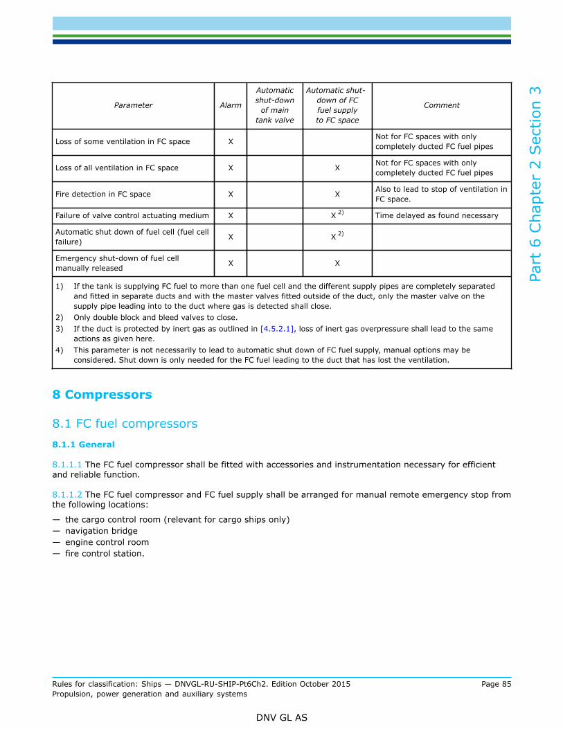
Part
6 C
hapt
er 2
Sec
tion
3
Rules for classification: Ships — DNVGL-RU-SHIP-Pt6Ch2. Edition October 2015 Page 85Propulsion, power generation and auxiliary systems
DNV GL AS
Parameter Alarm
Automaticshut-down
of maintank valve
Automatic shut-down of FCfuel supplyto FC space
Comment
Loss of some ventilation in FC space X Not for FC spaces with onlycompletely ducted FC fuel pipes
Loss of all ventilation in FC space X X Not for FC spaces with onlycompletely ducted FC fuel pipes
Fire detection in FC space X X Also to lead to stop of ventilation inFC space.
Failure of valve control actuating medium X X 2) Time delayed as found necessary
Automatic shut down of fuel cell (fuel cellfailure) X X 2)
Emergency shut-down of fuel cellmanually released X X
1) If the tank is supplying FC fuel to more than one fuel cell and the different supply pipes are completely separatedand fitted in separate ducts and with the master valves fitted outside of the duct, only the master valve on thesupply pipe leading into to the duct where gas is detected shall close.
2) Only double block and bleed valves to close.3) If the duct is protected by inert gas as outlined in [4.5.2.1], loss of inert gas overpressure shall lead to the same
actions as given here.4) This parameter is not necessarily to lead to automatic shut down of FC fuel supply, manual options may be
considered. Shut down is only needed for the FC fuel leading to the duct that has lost the ventilation.
8 Compressors
8.1 FC fuel compressors8.1.1 General
8.1.1.1 The FC fuel compressor shall be fitted with accessories and instrumentation necessary for efficientand reliable function.
8.1.1.2 The FC fuel compressor and FC fuel supply shall be arranged for manual remote emergency stop fromthe following locations:
— the cargo control room (relevant for cargo ships only)— navigation bridge— engine control room— fire control station.
Part
6 C
hapt
er 2
Sec
tion
3
Rules for classification: Ships — DNVGL-RU-SHIP-Pt6Ch2. Edition October 2015 Page 86Propulsion, power generation and auxiliary systems
DNV GL AS
9 Manufacture, workmanship and testing
9.1 Liquefied gas tank9.1.1 Manufacture and testing
9.1.1.1 Tests related to welding and tank testing shall be in accordance with Pt.5 Ch.7 Sec.6 [5], Pt.5 Ch.7Sec.6 [6], Pt.5 Ch.7 Sec.4 [5.2.3] and Pt.5 Ch.7 Sec.4 [5.2.4].
9.2 FC Fuel piping systems9.2.1 FC fuel pipes and ducting
9.2.1.1 The FC fuel pipes and ducting shall be tested as given inSec.5 [11.2]. Butt welded joints of hydrogensupply pipes shall be subjected to 100% radiographic testing.
9.2.2 Valves
9.2.2.1 Each type of valve to be used at working temperatures below minus 55ºC shall be prototype testedas given in Pt.5 Ch.7 Sec.5 [13.1].
9.2.2.2 Valves for use in hydrogen pipes located in ventilated spaces with fully welded hydrogen pipes,as specified in [4.4.1.1] 2), shall be tightness tested with hydrogen to show that there is no leakage ofhydrogen from the valve.
9.2.3 Expansion bellows
9.2.3.1 Expansion bellows intended for use in FC fuel systems shall be prototype tested as given in Pt.5 Ch.7Sec.5 [13.2].
9.3 On-board testing of FC plant9.3.1 General
9.3.1.1 Testing after installation on-board of the whole system shall be performed in different relevant loadconditions (typically: “start up”, “normal running”, “full load”) and shall as a minimum always verify that, inthe event of the following faults, the FC system is automatically transferred into a safe condition:
— alarm of the fire detection devices— alarm of the gas detection system— failure of the power supply— failure of the programmable logic controllers (PLCs)— triggering of the protective devices— faults in the protective devices— faults in the protective system
Further tests may be required based on the approved FMEAs and related test programs.
9.3.1.2 For notation FC(Power), the interaction of the FC system with the ship systems shall be tested asfollows:
— power generation by the FC system alone— FC system together with conventional shipboard generation of electrical power

Part
6 C
hapt
er 2
Sec
tion
3
Rules for classification: Ships — DNVGL-RU-SHIP-Pt6Ch2. Edition October 2015 Page 87Propulsion, power generation and auxiliary systems
DNV GL AS
— FC system together with batteries— change-over to the emergency source of electrical power— switching the FC system online or offline— testing of sudden load variations and load rejection
If the FC system constitutes the main propulsion system of the ship, it shall be verified that the ship hasadequate propulsion power in all maneuvering situations

Part
6 C
hapt
er 2
Sec
tion
4
Rules for classification: Ships — DNVGL-RU-SHIP-Pt6Ch2. Edition October 2015 Page 88Propulsion, power generation and auxiliary systems
DNV GL AS
SECTION 4 FUEL TREATMENT AND CONDITIONING SYSTEMS - FUEL
1 General
1.1 IntroductionThe additional class notation Fuel applies to systems and equipment utilised for the treatment of residualfuel for use in diesel engines. Residual fuel oil is so viscous that it has to be handled by a special fueltreatment system before use, and it may contain relatively high amounts of pollutants, particularly sulphur,which forms sulphur dioxide upon combustion.
1.2 ScopeThe scope of additional class notation Fuel ensures that the fuel treatment system will reduce the content ofundesired impurities to a level safe for diesel engine use, and that the fuel is delivered to the engine with thecorrect viscosity and pressure throughout the full operating range of engine power.
1.3 ApplicationVessels with fuel systems and equipment complying with the rules in this section may be assigned theadditional class notation Fuel (- cSt, - kg/m3, -°C) The numbers in brackets indicate the maximumviscosity in cSt at 50°C, the maximum density in kg/m3 at 15°C of the fuel oil and the minimum outside airtemperature for which the installations are approved. Redundancy requirements are included in this sectionof the rules, as is the possibility of having two different bunker batches that may be stored and handledwithout need for mixing.
1.4 Environmental conditions
1.4.1 For determining heating capacity the following minimum temperatures apply:
— Sea: 0°C— Outside air temperature: 0°C, if a lower temperature is not defined in the class notation.
1.5 Definitions1.5.1 Definitions
Table 1 Definitions
Term Definition
Booster systemis the pressurised system of pumps, heaters, valves, filters and other equipment permanentlyinstalled to provide the transfer of fuel from the day tank to the engine high pressure fuelpumps.
Fuelas used in this context is an organic liquid hydrocarbon oil derived from petroleum refining. Thisdoes not preclude the incorporation of small amounts of additives intended to improve someaspects of performance.
Fuel additives are chemical substances used to improve the fuel treatment efficiency and or fuel performancein diesel engines as well as minimising harmful effects.

Part
6 C
hapt
er 2
Sec
tion
4
Rules for classification: Ships — DNVGL-RU-SHIP-Pt6Ch2. Edition October 2015 Page 89Propulsion, power generation and auxiliary systems
DNV GL AS
Term Definition
Fuel qualityis determined with reference to values of parameters describing chemical and physicalproperties. It is assumed that fuels containing contamination in excess of that specified in ISO8217/latest version/ Grade RMH55 are not bunkered.
Fuel storage system incorporates tanks for fuel storage which are not intended to influence the cleaning process(settling and drainage of contaminants).
Separator is a permanently fitted centrifuge for fuel cleaning.
Transfer system incorporate the system of pipes, valves, filters and pumps intended for the transfer of fuelbetween storage tanks and from storage tanks to the treatment system.
Treatment systemincorporates the system of tanks, pipes, valves heaters, filters, pumps, separators and otherpermanently installed components intended for cleaning and conditioning of the fuel. It alsocomprises arrangements for chemical treatment of the fuel by the use of fuel additives.
1.6 CertificationTable 2 Certification required
Object Certificatetype
Issuedby
Certificationstandard* Additional description
Separators TA Society Fuel Oil
*Unless otherwise specified the certification standard is DNV GL Rules.
1.7 Documentation1.7.1 Plans and particularsAdditional to the documentation required by other relevant rules, the plans and particulars listed in Table 3shall be submitted for approval:
Table 3 Documentation requirements class notation Fuel
Object Documentation type Additional description Info
S010 – Piping diagram (PD)Fuel oil transfer pipes with heat tracing (including anylow sulphur fuel change over system for SOx EmissionControl area -SECA)
AP
Z100 – Specification Pipes with heat tracing and heated tanks with insulation AP
Z030 – Arrangement plan Heating coils in fuel tank AP
S120 – Heat balance calculation Comprising heated fuel tanks, fuel pre-heaters and heatlosses, throughout the system AP
Z253 - Test procedure for quayand sea trial Including log of temperatures, viscosity, alarms, etc. FI
Z161 – Operation manual Including bunkering procedures AP
Fuel oil system
Z250 – Procedure Fuel oil samples handling and records in connection withMARPOL Annex VI. FI

Part
6 C
hapt
er 2
Sec
tion
4
Rules for classification: Ships — DNVGL-RU-SHIP-Pt6Ch2. Edition October 2015 Page 90Propulsion, power generation and auxiliary systems
DNV GL AS
Object Documentation type Additional description Info
Fuel oil controland monitoringsystem
I200 – Control and monitoringsystem documentation Fuel pre-treatment system AP
AP=For approval; FI=For information
1.7.2 For general requirements for documentation, including definition of the info codes, see Pt.1 Ch.3 Sec.2.
1.7.3 For a full definition of the documentation types, see Pt.1 Ch.3 Sec.3.
1.8 General requirements1.8.1 System design principles
1.8.1.1 The fuel treatment plant shall be designed and installed in accordance with relevant parts of the rulesunless otherwise stated in this section.
1.8.1.2 The fuel system shall ensure that:
— the content of undesired impurities is reduced to a level safe for diesel engine use.— the fuel is delivered to the engine with the correct viscosity and pressure throughout the full operating
range of engine power.— the system provides redundancy as required in relevant rules.— two different bunker batches may be stored and handled without need for mixing.
1.8.2 Fuel operation manual
1.8.2.1 A manual describing systems, equipment and guidance for bunkering, handling of fuel and operationof systems shall be provided.The fuel operation manual shall emphasize measures and procedures in order to minimize the mixing of oldand or new or incompatible fuel oils during bunkering and change over operations.
2 System arrangements and components
2.1 System for storage and transfer of fuel2.1.1 Bunker manifolds
2.1.1.1 An adequate bunker manifold shall be provided on each side equipped with spill tray with a volume ofat least 160 litre capacity to prevent oil pollution during bunkering operations.
2.1.1.2 An approved arrangement for sampling of fuel shall be provided at each of the bunker manifolds or inthe fuel bunkering line.
2.1.2 Fuel storage tanks
2.1.2.1 At least two storage tanks shall be provided. If only two tanks are installed, the smallest tank shallnot to be less than one third of the total tank capacity.

Part
6 C
hapt
er 2
Sec
tion
4
Rules for classification: Ships — DNVGL-RU-SHIP-Pt6Ch2. Edition October 2015 Page 91Propulsion, power generation and auxiliary systems
DNV GL AS
2.1.2.2 Arrangement enabling representative fuel sampling shall be provided.
2.1.2.3 All tanks shall be provided with sufficient heating capacity to keep the bulk temperature of the oil onat least 45°C.
2.1.2.4 Isolating valves for heating coils in each tank shall be provided. Sampling cocks in condensate returnlines to be provided.
2.1.2.5 The storage tanks shall be provided with monitoring equipment for temperature and level.
2.1.3 Fuel transfer system
2.1.3.1 The transfer pumps shall be located as low as possible.
2.1.3.2 As far as practical, long suction lines shall be avoided.
2.1.3.3 Transfer lines shall be provided with heat tracing and insulation.
2.2 Fuel oil settling and daily service tanks2.2.1 Tank arrangement
2.2.1.1 At least two settling and two daily service tanks shall be provided.
2.2.1.2 Settling and daily service tanks shall not be located adjacent to the ship's side.Guidance note:Minimum distance between hull and tank bulkhead should be 760 mm for inspection access.
---e-n-d---of---g-u-i-d-a-n-c-e---n-o-t-e---
2.2.2 Settling tanks
2.2.2.1 The usable capacity of each settling tank shall be sufficient for 24 hours operation at maximum fuelconsumption.
2.2.2.2 Heating capacity, sufficient to increase the temperature of the oil from 45°C to at least 70°C within12 hours, shall be provided.
2.2.2.3 The tanks shall be provided with suitable openings for access and ventilation to allow effective tankcleaning.
2.2.2.4 The tank bottom shall be so designed that precipitated material may be drained to the sludge tank byopening an easily accessible drain valve. Tank bottom shall be sloped towards the drain outlet.
2.2.2.5 Suction outlets for separators shall be placed above bottom to avoid precipitated material to escape.Minimum distance from the bottom to the suction shall be 500 mm.
2.2.2.6 For sludge removal by use of separator, a bottom suction is required.
2.2.3 Daily service tanks
2.2.3.1 The usable capacity of each daily service tank shall be sufficient for 12 hours operation at maximumfuel consumption.

Part
6 C
hapt
er 2
Sec
tion
4
Rules for classification: Ships — DNVGL-RU-SHIP-Pt6Ch2. Edition October 2015 Page 92Propulsion, power generation and auxiliary systems
DNV GL AS
2.2.3.2 Heating capacity, sufficient to increase the temperature of the oil from 70°C to at least 90°C within 6hours, shall be provided.
2.2.3.3 The tanks shall be provided with suitable openings for access and ventilation to allow effective tankcleaning
2.2.3.4 The tank bottom shall be constructed with smooth bottom and with slope towards the drain outlet.
2.2.3.5 The suction to the booster system shall be placed minimum 500 mm above bottom to avoidprecipitated material to escape.
2.2.3.6 The arrangement of the tanks and interconnected piping shall be such that unintentional ingress offuel from one tank to another is avoided.
2.2.3.7 Overflow pipe to run from the bottom of the service tank to the top of the settling tank (above theoverflow discharge from the settling tank).
2.3 Fuel treatment system2.3.1 General
2.3.1.1 The fuel treatment system shall at least consist of:
— centrifugal separators— fuel heaters— automatic filters— booster system including pressurised mixing tank— automatic viscosity control equipment— automatic temperature control.
2.3.2 Centrifugal separators
2.3.2.1 The capacity of separators, their number and configuration shall be such that with any unit out ofoperation, the system shall maintain an adequate performance at the maximum fuel consumption.
Guidance note:Capacity of separators will be considered equal to Certified Flow Rate (for the viscosity class in question) as determined by the TypeApproval Programme for Fuel Oil Separators.
---e-n-d---of---g-u-i-d-a-n-c-e---n-o-t-e---
2.3.2.2 Heaters, control systems, pumps and other auxiliary equipment for the cleaning process shall be sodesigned that the fuel is kept at the condition necessary for the separators to function as required.
2.3.2.3 Fuel feed rate to separators shall be controlled by means of rpm (frequency) of feed pump. (Or otherequal means to control flow rate approved by the Society in each case).
2.3.2.4 Fuel heaters for separators shall have automatic temperature control. Controller shall haveproportional and integral function (PI-controller). Possibility for manual control shall be arranged.

Part
6 C
hapt
er 2
Sec
tion
4
Rules for classification: Ships — DNVGL-RU-SHIP-Pt6Ch2. Edition October 2015 Page 93Propulsion, power generation and auxiliary systems
DNV GL AS
2.3.2.5 For steam heating arrangements condensate drain from heaters shall be controlled by float operateddrain traps (or other equal means approved by the Society in each case). Drain traps discharge shall be bygravity.
Guidance note:If the pressure of the heating medium inside the heater is sufficient to displace the condensate to the condensate tank located ata higher level, this is considered equivalent to gravity drain.
---e-n-d---of---g-u-i-d-a-n-c-e---n-o-t-e---
2.3.2.6 The discharge pipe to the sludge tank shall be made as short and vertical as possible. The pipediameter shall not be less than the separator sludge outlet stud.
2.3.2.7 Centrifugal separators shall preferably be positioned on top of the sludge tank.
2.3.2.8 A fixed arrangement for sampling fuel before and after the separator(s) shall be provided.
2.3.3 Fuel heaters and viscosity control equipment
2.3.3.1 The system of fuel heaters shall be designed with built in redundancy.
2.3.3.2 With any one heater out of service, the remaining heaters shall have the capacity of raising the fueltemperature sufficiently to achieve a viscosity required for the correct injection of fuel into the diesel engineat a flow rate corresponding to 120% of the maximum fuel consumption.
2.3.3.3 Heaters shall be designed with a maximum surface temperature of the heating elements of 170°C forsteam and 200°C for thermal oil heating systems.
Guidance note:170°C surface temperature normally corresponds to a heat load of 10 kW/m2.
---e-n-d---of---g-u-i-d-a-n-c-e---n-o-t-e---
2.3.3.4 Fuel heaters in the booster system shall be provided with control equipment maintaining the desiredviscosity.
2.3.3.5 The viscosity controller shall have proportional and integral action (PI controller).
2.3.3.6 Means for manual temperature control of the heaters shall be arranged.
2.3.3.7 For steam heating arrangements condensate drains from heaters to be controlled by float operateddrain traps (or other equal means approved by the Society in each case). Drain trap discharge shall be bygravity.

Part
6 C
hapt
er 2
Sec
tion
5
Rules for classification: Ships — DNVGL-RU-SHIP-Pt6Ch2. Edition October 2015 Page 94Propulsion, power generation and auxiliary systems
DNV GL AS
SECTION 5 GAS FUELLED SHIP INSTALLATIONS - GAS FUELLED
1 General
1.1 IntroductionThe additional class notation Gas fuelled provides criteria for the safe and environmentally friendlyarrangement and installation of machinery for propulsion and auxiliary purposes, using gas as fuel.
1.2 ScopeThe scope for additional class notation Gas fuelled includes requirements for the ship's gas fuel system,covering all aspects of the installation, from the ship's gas fuel bunkering connection up to and including thegas consumers. This section has requirements for arrangement and location of gas fuel tanks and all spaceswith fuel gas piping and installations, including requirements for the entrances to such spaces. Hazardousareas and spaces, due to the fuel gas installations, are defined. Requirements for control, monitoring andsafety systems for the fuel gas installations are included. For tank design and gas piping detail design, seealso Pt.5 Ch.7. Requirements for manufacture, workmanship and testing are included, also referring to detailsgiven in Pt.5 Ch.7. Bunkering procedures are required for approval as part of the Operation Manual. Thebunkering processes and crew training are not part of the scope for this section of the rules.
1.3 ApplicationThe additional class notation Gas fuelled applies to installations using gas as fuel in ships. This includesinternal combustion engines, boilers and gas turbines. The installations may run on gas only or be dual fuelinstallations. Gas may be stored in a gaseous or liquefied state. The use of gas as fuel in ships, other thanLNG carriers, is not yet covered by international conventions, and such installations will need additionalacceptance by flag authorities. The International Code of Safety for Ships using Gases or other Low-flashpoint Fuels (IGF Code) is adopted by IMO by resolution MSC.391(95). The IGF Code will take effect on 1January 2017. IMO resolution MSC.285(86) 'Interim Guidelines on Safety for Gas Fuelled Engine Installationsin Ships' provides international guidelines. Until the IGF Code enters into force, either IMO resolutionMSC.285(86) or the IGF Code may be enforced by the flag state. Collision and grounding protection for fueltanks are covered by statutory requirements. The rules are applicable for installations where natural gas isused as fuel. If other gases are used as fuel, then special consideration will need to be taken, and additionalrequirements may be relevant. These rules are not applicable to gas carriers. Ships built with machinerysatisfying the requirements of the rules in this section, may be assigned the additional class notation Gasfuelled.
1.4 Classification1.4.1 Survey extent
1.4.1.1 Survey requirements for ships with the class notation Gas fuelled are given in the Rules forClassification of Ships, Pt.7 Ch.1 Sec.2 [1] and Pt.7 Ch.1 Sec.2 [3], Pt.7 Ch.1 Sec.3 [3] and Pt.7 Ch.1 Sec.4[3].

Part
6 C
hapt
er 2
Sec
tion
5
Rules for classification: Ships — DNVGL-RU-SHIP-Pt6Ch2. Edition October 2015 Page 95Propulsion, power generation and auxiliary systems
DNV GL AS
1.5 Definitions1.5.1 Terms
Table 1 Terms
Terms Definition
accommodation spacesthose spaces used for public spaces, corridors, lavatories, cabins, offices, hospitals, cinemas,game and hobby rooms barber shops, pantries containing no cooking appliances and similarspaces
breadth (B) the greatest moulded breadth of the ship at or below the deepest draught (summer load linedraught). See SOLAS regulation II-1/2.8
bunkering the transfer of liquefied or gaseous fuel from land based or floating facilities into a ships'permanent tanks or connection of portable tanks to the fuel supply system.
CNG compressed natural gas.
certified safe typeelectrical equipment that is certified safe by the relevant authorities recognized by theAdministration or its recognized organization acting on its behalf for operation in a flammableatmosphere based on a recognized standard.
control station those spaces defined in SOLAS chapter II-2 and in the context of these rules, also the enginecontrol room
design temperature for selection of materials, the minimum temperature at which liquefied gas fuel may be loadedor transported in the liquefied gas fuel tanks
design vapour pressure"P0"
the maximum gauge pressure, at the top of the tank, used as a parameter for the design of thetank.
Double block and bleedvalve
a set of two valves in series in a pipe, and a third valve enabling the pressure release from thepipe between those two valves. The arrangement may also consist of a two-way valve and aclosing valve instead of three separate valves
dual fuel engines in this context engines that can burn gaseous and liquefied fuel simultaneously and in a widevariety of proportions, or can operate successively on oil fuel and gas
ESD emergency shutdown
enclosed space
any space which, in the absence of artificial ventilation, the ventilation will be limited and anyexplosive atmosphere will not be dispersed naturally
Guidance note:See also definition in IEC 60092-502:1999
---e-n-d---of---g-u-i-d-a-n-c-e---n-o-t-e---
explosion a deflagration event of uncontrolled combustion
explosion pressurerelief
measures provided to prevent the explosion pressure in a container or an enclosed spaceexceeding the maximum overpressure the container or space is designed for, by releasing theoverpressure through designated openings
filling limit (FL) the maximum liquid volume in a fuel tank relative to the total tank volume when the liquid fuelhas reached the reference temperature.
fuel natural gas, either in its liquefied or gaseous state.

Part
6 C
hapt
er 2
Sec
tion
5
Rules for classification: Ships — DNVGL-RU-SHIP-Pt6Ch2. Edition October 2015 Page 96Propulsion, power generation and auxiliary systems
DNV GL AS
Terms Definition
fuel containmentsystem
the arrangement for the storage of fuel including tank connections. It includes where fitted, aprimary and secondary barrier, associated insulation and any intervening spaces, and adjacentstructure if necessary for the support of these elements. If the secondary barrier is part of thehull structure it may be a boundary of the fuel storage hold space
fuel preparation room any space containing pumps, compressors and/or vaporizers for fuel preparation purposes
fuel storage hold spacethe space enclosed by the ship's structure in which a fuel containment system is situated. Iftank connections are located in the fuel storage hold space, it will also be a tank connectionspace, and will have to fulfil the requirements for both spaces
gas defined as a fluid having a vapour pressure exceeding 2.8 bar absolute at a temperature of37.8°C
gas consumer any unit within the ship using gas as a fuel.
gas control systems providing control and monitoring for bunkering, gas storage and gas supply to machinery
gas only engine an engine capable of operating on gas only, and not able to switch over to operation on anyother type of fuel
gas safety systems the safety systems for bunkering, gas storage and gas supply to machinery
gas valve unit spaces
spaces or boxes containing valves for control and regulation of gas supply before the consumer
Guidance note:The gas valve unit is by different suppliers also called for instance GVU, gas regulating unit, GRUor gas train.
---e-n-d---of---g-u-i-d-a-n-c-e---n-o-t-e---
hazardous area
an area in which an explosive gas atmosphere is or may be expected to be present, inquantities such as to require special precautions for the construction, installation and use ofequipment.
Hazardous areas are divided into zone 0, 1 and 2 as defined below and according to the areaclassification specified in [8]
zone0 Area in which an explosive gas atmosphere or a flammable gas with a flash point
below 60°C is present continuously or is present for long periods.zone1 Area in which an explosive gas atmosphere or a flammable gas with a flash point
below 60°C is likely to occur in normal operations.
zone2
Area in which an explosive gas atmosphere or a flammable gas with a flash pointbelow 60°C is not likely to occur in normal operation and, if it does occur, is likely todo so only infrequently and will exist for a short period only.
Guidance note:The definition of hazardous area is only related to the risk of explosion. In this context, health, safetyand environmental issues, i.e. toxicity, is not considered.
---e-n-d---of---g-u-i-d-a-n-c-e---n-o-t-e---
high fire risk space a high fire risk space as defined in SOLAS Ch.II-2
high pressure a maximum working pressure greater than 10 bar
independent tanks self-supporting, do not form part of the ship's hull and are not essential to the hull strength
interbarrier space the space between a primary and a secondary barrier, whether or not completely or partiallyoccupied by insulation or other material

Part
6 C
hapt
er 2
Sec
tion
5
Rules for classification: Ships — DNVGL-RU-SHIP-Pt6Ch2. Edition October 2015 Page 97Propulsion, power generation and auxiliary systems
DNV GL AS
Terms Definition
LEL lower explosion limit
LNG liquefied natural gas
length (L) the length as defined in the International Convention on Load Lines in force
loading limit (LL) the maximum allowable liquid volume relative to the tank volume to which the tank may beloaded.
MARVS the maximum allowable relief valves setting
master gas fuel valve an automatic valve in the gas supply line to each engine located outside the machinery space
membrane tanks non-self-supporting tanks that consist of a thin liquid and gas tight layer (membrane)supported through insulation by the adjacent hull structure
non-hazardous area an area in which an explosive gas atmosphere is not expected to be present in quantities suchas to require special precautions for the construction, installation and use of equipment
north Atlanticenvironment shall be in accordance with the definitions specified in IACS Recommendation 034
open decka deck that is open at one or both ends and equipped with adequate natural ventilation that iseffective over the entire length of the deck through permanent openings distributed in the sidepanels or in the deck above
reference temperature the temperature corresponding to the vapour pressure of the fuel in a fuel tank at the setpressure of the PRVs.
secondary barrierthe outer element of a fuel containment system, designed to afford temporary containment ofany envisaged leakage of liquefied fuel through the primary barrier, and to prevent that thetemperature of the ship's structure is lowered to an unsafe level
secondary enclosure the enclosure around fuel piping designed to prevent liquefied and/or gaseous fuel leaking fromthe fuel piping system
semi-enclosed spacea space where the natural conditions of ventilation are notably different from those on opendeck, due to the presence of structures such as roofs, windbreaks and bulkheads, and whichare so arranged that dispersion of gas may not occur
service spacesspaces outside the cargo area used for galleys, pantries containing cooking appliances, lockers,mail and specie rooms, store rooms, workshops other than those forming part of the machineryspaces and similar spaces and trunks to such spaces
source of release a point or location from which a gas, vapour, mist or liquid may be released into theatmosphere so that an explosive atmosphere could be formed.
tank connection space the gastight space surrounding the bunker tank connections and tank valves
unacceptable loss ofpower
that it is not possible to sustain or restore normal operation of the propulsion machinery inthe event of one of the essential auxiliaries becoming inoperative, in accordance with SOLASregulation II-1/26.3
vapour pressure the equilibrium pressure of the saturated vapour above the liquid, expressed in bar absolute ata specified temperature

Part
6 C
hapt
er 2
Sec
tion
5
Rules for classification: Ships — DNVGL-RU-SHIP-Pt6Ch2. Edition October 2015 Page 98Propulsion, power generation and auxiliary systems
DNV GL AS
1.6 Documentation requirements1.6.1 Plans and particulars
1.6.1.1 Documentation shall be submitted as required by Table 2
Table 2 Documentation requirements
Object Documentation type Additional description Info
Z050 – Designphilosophy
Including information on the machinery configuration, machineryspace arrangements, fuel arrangements, shut down philosophy,redundancy considerations etc.Shall be submitted before other documentation, to give support forapproval of these.
FI
Z071 – Failure modeand effect analysis(FMEA)
For non-conventional gas fuelled propulsion machineryarrangements, covering single failure in active components orsystems. See [5.1.2.4].
AP
Propulsionand steeringarrangements,general
Z253 - Test procedurefor quay and sea trial Redundancy and failure modes based on FMEA AP
Z030 – Arrangementplan
Including:
— machinery and boiler spaces, accommodation, service andcontrol station spaces
— fuel containment systems— fuel preparation rooms— fuel bunkering pipes with shore connections— tank hatches, vent pipes and any other openings to the fuel
tanks— ventilating pipes, doors and openings to fuel preparation
rooms, and other hazardous areas— entrances, air inlets and openings to accommodation, service
and control station spaces.
AP
Z253 - Test procedurefor quay and sea trial
Including testing of safety shut downs in accordance with thedocumentation type "G130 - Cause and effect diagram" AP
Z160 - Operationmanual [1.8.1.1] AP
Z240 – Calculationreport Explosion analysis (ESD protected machinery spaces) FI
Fuel gas system
C030 – Detaileddrawing Gastight bulkhead penetrations. AP
Fuel gas tanksC030 – Detaileddrawing
— tanks— supports and stays— secondary barriers— insulation— marking plates— tank connection space— tank hatches, pipes and any openings to the gas tanks.
AP

Part
6 C
hapt
er 2
Sec
tion
5
Rules for classification: Ships — DNVGL-RU-SHIP-Pt6Ch2. Edition October 2015 Page 99Propulsion, power generation and auxiliary systems
DNV GL AS
Object Documentation type Additional description Info
C040 – Designanalysis
— design loads and structural analysis of fuel tanks— complete stress analysis for independent tanks type B and type
C.— membrane tanks
FI
H130 – Fabricationspecification Building tolerances AP
S070 – Pipe strengthanalysis
Strength analysis of piping inside outer tank (vacuum insulatedtank.) FI
S080 – Thermal stressanalysis When design temperature is below -110°C. FI
C050 – Non-destructive testing(NDT) plan
Including
— NDT procedures— information about strength and tightness testing
AP
Z265 - Calculationreport
Holding time calculation when pressure accumulation is used asboil off gas handling method. FI
Z265 - Calculationreport Filling limit curve FI
M060 – Weldingprocedures (WPS) AP
M010 – Materialspecifications, metals
Including connected pipes
— forming procedure of dished ends— specification of stress relieving procedures for independent
tanks type C (thermal or mechanical).
FI
Z030 – Arrangementplan
Overview of tanks with all tank connections and tank connectionspace FI
Z250 – Procedure Cooling down. AP
C030 – Detaileddrawing Safety relief valves and associated vent piping. AP
S030 – Capacityanalysis
Safety relief valves and associated vent piping. Including backpressure. AP
Z100 – Specification Safety relief valves and associated vent piping. AP
S010 – Piping diagram(PD)
Gas freeing and purging system.Including vent lines for safetyrelief valves or similar piping, and ducts for gas pipes. AP
I200 – Control andmonitoring systemdocumentation
— functionality as required by [9] AP
Fuel gas control andmonitoring system I260 – Field
instruments periodictest plan
See [1.8.1.2] AP

Part
6 C
hapt
er 2
Sec
tion
5
Rules for classification: Ships — DNVGL-RU-SHIP-Pt6Ch2. Edition October 2015 Page 100Propulsion, power generation and auxiliary systems
DNV GL AS
Object Documentation type Additional description Info
I200 – Control andmonitoring systemdocumentation
— functionality as required by Table 7AP
Fuel gas safetysystem
G130 – Cause andeffect diagram
— shall cover the safety functions as required by Table 7— interfaces to other safety and control systems shall be included
AP
C030 – Detaileddrawing Insulation of low temperature piping. FI
S010 – Piping diagram(PD)
Including vent lines for safety relief valves or similar piping, andducts for gas pipes AP
S060 – Pipe routingsketch FI
S080 – Thermal stressanalysis When design temperature is below -110°C FI
S090 – Specificationof valves, flanges andfittings
Including offsets, loops, bends, expansion elements such asbellows and slip joints (only inside tanks). For valves intended forservice with a design temperature below -55°C, documentation ofleak test and functional test at design temperature (type test) shallbe included.
FI
Z253 - Test procedurefor quay and sea trial
Functional tests of all piping systems including valves, fittings andassociated equipment for handling fuel (liquefied or gaseous) AP
Z100 – Specification Closing time of shutdown valves in liquefied gas fuel lines operatedby the safety system FI
Z100 – Specification Insulation of low temperature piping. FI
Fuel gas pipingsystem
Z030 – Arrangementplan
Vent masts, including location and details of outlets from fuel tankssafety relief valves. AP
Fuel gas drip trays Z030 – Arrangementplan
Hull protection beneath piping for liquefied fuel where leakagesmay be anticipated, such as at shore connections and at pumpseals. Including specification.
AP
Fuel gas coolingsystem
S010 – Piping diagram(PD) AP
Fuel gas heatingsystem
S010 – Piping diagram(PD) AP
Exhaust gas system S010 – Piping diagram(PD)
Including arrangement of explosion relief or verification of strengthof piping system, ref. [5.5] AP
Hazardous areaclassification
G080 – Hazardousarea classificationdrawing
AP
Air lockarrangements
Z030 – Arrangementplan Location and construction details, including alarm equipment. AP
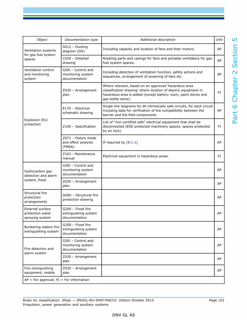
Part
6 C
hapt
er 2
Sec
tion
5
Rules for classification: Ships — DNVGL-RU-SHIP-Pt6Ch2. Edition October 2015 Page 101Propulsion, power generation and auxiliary systems
DNV GL AS
Object Documentation type Additional description Info
S012 – Ductingdiagram (DD) Including capacity and location of fans and their motors. APVentilation systems
for gas fuel systemspaces C030 – Detailed
drawingRotating parts and casings for fans and portable ventilators for gasfuel system spaces. AP
Ventilation controland monitoringsystem
I200 – Control andmonitoring systemdocumentation
Including detection of ventilation function, safety actions andsequences, arrangement of powering of fans etc. AP
Z030 – Arrangementplan
Where relevant, based on an approved ‘hazardous areaclassification drawing’ where location of electric equipment inhazardous area is added (except battery room, paint stores andgas bottle store).
FI
E170 – Electricalschematic drawing
Single line diagrams for all intrinsically safe circuits, for each circuitincluding data for verification of the compatibility between thebarrier and the field components.
AP
Z100 – SpecificationList of “non-certified safe” electrical equipment that shall bedisconnected (ESD protected machinery spaces, spaces protectedby air lock)
FI
Z071 – Failure modeand effect analysis(FMEA)
If required by [8.1.1] AP
Explosion (Ex)protection
Z163 - Maintenancemanual Electrical equipment in hazardous areas. FI
I200 – Control andmonitoring systemdocumentation
APHydrocarbon gasdetection and alarmsystem, fixed Z030 – Arrangement
plan AP
Structural fireprotectionarrangements
G060 – Structural fireprotection drawing AP
External surfaceprotection waterspraying system
G200 – Fixed fireextinguishing systemdocumentation
AP
Bunkering station fireextinguishing system
G200 – Fixed fireextinguishing systemdocumentation
AP
I200 – Control andmonitoring systemdocumentation
APFire detection andalarm system
Z030 – Arrangementplan AP
Fire extinguishingequipment, mobile
Z030 – Arrangementplan AP
AP = For approval; FI = For information

Part
6 C
hapt
er 2
Sec
tion
5
Rules for classification: Ships — DNVGL-RU-SHIP-Pt6Ch2. Edition October 2015 Page 102Propulsion, power generation and auxiliary systems
DNV GL AS
1.6.1.2 For general requirements for documentation, including definition of the Info codes, see Pt.1 Ch.3Sec.2
1.6.1.3 For a full definition of the documentation types, see Pt.1 Ch.3 Sec.3.
1.7 Certification requirements for manufacturers1.7.1 Certification requirements
1.7.1.1 Products shall be certified as required by Table 3.
Table 3 Certification required
Object Certificatetype Issued by Certification
standard* Additional description
Gas/Dual FuelEngines PC Society In accordance with Pt.4 Ch.3
Process pressurevessels PC Society Shall be certified as Class I pressure vessels in
accordance with Pt.4 Ch.7
Pumps PC Society In accordance with Pt.5 Ch.7
Compressors PC Society In accordance with Pt.4 Ch.5
Valves in fuel system PC SocietyFor valves with design temperature below 0°CIn accordance with Pt.5 Ch.7 Sec.5 (irrespective ofsize)
Valves in fuel system PC SocietyFor valves with design pressure above 10 barIn accordance with Pt.5 Ch.7 Sec.5 (irrespective ofsize)
Valves in fuel system MC ManufacturerFor valves with design pressure equal to or lowerthan 10 bar, and design temperature equal to orabove 0°C
Expansion bellows PC Society In accordance with Pt.5 Ch.7
Fuel gas control andmonitoring systems PC Society Shall be certified in accordance with Pt.4 Ch.9
Fuel gas safetysystem PC Society Shall be certified in accordance with Pt.4 Ch.9
Hydrocarbon gasdetection and alarmsystem, fixed
PC Society Shall be certified in accordance with Pt.4 Ch.9
Electric motors PC SocietyShall be certified in accordance with Pt.4 Ch.8when used in gas supply systems and ventilationsystems
Electric motorstarters PC Society
Shall be certified in accordance with Pt.4 Ch.8when used in gas supply systems and ventilationsystems
*Unless otherwise specified the certification standard is DNV GL Rules.

Part
6 C
hapt
er 2
Sec
tion
5
Rules for classification: Ships — DNVGL-RU-SHIP-Pt6Ch2. Edition October 2015 Page 103Propulsion, power generation and auxiliary systems
DNV GL AS
1.7.1.2 For general certification requirements, see Pt.1 Ch.3 Sec.4.
1.7.1.3 For a definition of the certification types, see Pt.1 Ch.3 Sec.5
1.8 Onboard documentation1.8.1 Contents
1.8.1.1 An operational manual as described in Table 2 shall be kept on-board. The operation manual is ingeneral to give information regarding the following:
1) Arrangement and lay-out of the gas fuel supply system, including:
— Description of main components in the gas fuel supply system— A general description of how the fuel system is intended to work
2) Description of the safety shutdown system for the gas fuel supply system, including:
— How to respond to gas leakages in
— the fuel system— tank connection spaces— ESD protected machinery spaces— fuel preparation rooms
— How to respond to cryogenic leakages in
— the fuel system— tank connection spaces— fuel preparation rooms
— How to respond to loss of ventilation in
— the secondary enclosures in the gas fuel system— tank connection spaces— ESD protected machinery spaces— fuel preparation rooms
— How to respond to fire in
— the machinery space— on deck— fuel preparation room
3) Description of hazards in connection with inerted spaces and use of inert gas
4) Description of bunkering operations, including:
— how to prevent overfilling of tanks— how to control the tank pressure when bunkering— how to prevent release of fuel gases to atmosphere— how to gas free the bunkering system at termination of bunkering operation— safety precautions
5) Description of entry procedures for
— tank connection spaces— fuel preparation rooms— GVU enclosures

Part
6 C
hapt
er 2
Sec
tion
5
Rules for classification: Ships — DNVGL-RU-SHIP-Pt6Ch2. Edition October 2015 Page 104Propulsion, power generation and auxiliary systems
DNV GL AS
— hold spaces— other spaces where entry may constitute a hazard to the ship or personnel
6) Procedure for emptying and gas freeing of fuel gas tanks
7) Relevant drawings of the gas fuel installation, including:
— Fuel gas piping diagram— Fuel gas system arrangement plan— Ventilation systems
1.8.1.2 A plan for periodic test of all field instruments specified in these rules shall be kept onboard. The planshall include test intervals, description of how to perform the tests and description of what to observe duringthe tests.Test intervals for shutdown inputs and outputs (as required by Table 7) shall not exceed 6 months. For othersignals the test intervals shall not exceed 12 months.The plan may be included in the plan required for the class notation E0.
Guidance note:See Sec.2 [1.4] for information about plan for periodic test.
---e-n-d---of---g-u-i-d-a-n-c-e---n-o-t-e---
1.9 Signboards1.9.1 General
1.9.1.1 If the gas supply is shut off due to activation of an automatic valve, the gas supply shall not beopened until the reason for the disconnection is ascertained and the necessary precautions taken. A readilyvisible notice giving instruction to this effect shall be placed at the operating station for the shut-off valves inthe gas supply lines.
1.9.1.2 If a gas leak leading to a gas supply shutdown occurs, the gas fuel supply shall not be operated untilthe leak has been found and dealt with. Instructions to this effect shall be placed in a prominent position inthe machinery space.
1.9.1.3 A caution placard or signboard shall be permanently fitted in the machinery space stating that heavylifting, implying danger of damage to the gas pipes, shall not be done when the engine(s) is running on gas.
1.9.1.4 A signboard shall be permanently fitted on hatches to gas valve unit spaces in machinery spacesstating that the hatch shall only be opened after the gas supply system is shut down and gas free.
1.9.1.5 A signboard shall be permanently fitted on access openings to inerted spaces, warning of hazardsrelated to entry.
2 Materials
2.1 General2.1.1 Material requirements
2.1.1.1 Materials shall be in accordance with the requirements in Pt.2, unless otherwise stated.
2.1.1.2 Materials used in fuel containment and fuel piping systems shall comply with the requirements in Pt.5Ch.7 Sec.6 [1], Pt.5 Ch.7 Sec.6 [2], Pt.5 Ch.7 Sec.6 [3] and Pt.5 Ch.7 Sec.6 [4].
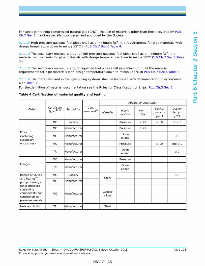
Part
6 C
hapt
er 2
Sec
tion
5
Rules for classification: Ships — DNVGL-RU-SHIP-Pt6Ch2. Edition October 2015 Page 105Propulsion, power generation and auxiliary systems
DNV GL AS
For tanks containing compressed natural gas (CNG), the use of materials other than those covered by Pt.5Ch.7 Sec.6 may be specially considered and approved by the Society.
2.1.1.3 High pressure gaseous fuel pipes shall as a minimum fulfil the requirements for pipe materials withdesign temperature down to minus 55°C in Pt.5 Ch.7 Sec.6 Table 4.
2.1.1.4 The secondary enclosure around high pressure gaseous fuel pipes shall as a minimum fulfil thematerial requirements for pipe materials with design temperature down to minus 55°C Pt.5 Ch.7 Sec.6 Table4 .
2.1.1.5 The secondary enclosure around liquefied fuel pipes shall as a minimum fulfil the materialrequirements for pipe materials with design temperature down to minus 165°C in Pt.5 Ch.7 Sec.6 Table 4.
2.1.1.6 The materials used in fuel gas piping systems shall be furnished with documentation in accordancewith Table 4.For the definition of material documentation see the Rules for Classification of Ships, Pt.1 Ch.3 Sec.5.
Table 4 Certification of material quality and testing
Additional description
Object Certificatetype 1) 2) Issued by Cert.
standard3)Material Piping
systemNom.Dia
Designpressure
(bar)
Designtemp.(°C)
MC Society Pressure > 25 > 10 or < 0
MC Manufacturer Pressure ≤ 25
MC Manufacturer Openended < 0
MC Manufacturer Pressure ≤ 10 and ≥ 0
Pipes(includingsecondaryenclosures)
TR Manufacturer Openended ≥ 0
MC Manufacturer Pressure
FlangesTR Manufacturer Open
ended
MC Society < 0
MC ManufacturerSteel
Bodies of valvesand fittings4),pump housings,other pressurecontainingcomponents notconsidered aspressure vessels
MC Manufacturer Copperalloys
Nuts and bolts TR Manufacturer Steel
Part
6 C
hapt
er 2
Sec
tion
5
Rules for classification: Ships — DNVGL-RU-SHIP-Pt6Ch2. Edition October 2015 Page 106Propulsion, power generation and auxiliary systems
DNV GL AS
Additional description
Object Certificatetype 1) 2) Issued by Cert.
standard3)Material Piping
systemNom.Dia
Designpressure
(bar)
Designtemp.(°C)
Notes
1) MC Material certificate2) TR Test Report3) Unless otherwise specified, the certification standard is the rules4) When fittings are made from plates or pipes, the certification requirements for pipes shall be applied also for the
pipe fittings.
3 Ship arrangement
3.1 Ship arrangement principles3.1.1 General principles
3.1.1.1 The fuel containment system installed in the ship shall be able to contain cryogenic leakages withoutdamaging other structures due to the low temperature, and to prevent gas spreading to non-hazardousspaces.
3.1.1.2 Areas with piping systems for liquefied gas fuel shall be arranged to contain leakages withoutdamaging other structures due to the low temperature, and to prevent gas spreading to non-hazardousspaces with the assumption that the piping system may leak anywhere in the system.
3.1.1.3 Areas with piping systems for gaseous fuel shall be arranged to prevent gas spreading to non-hazardous spaces, with the assumption that the piping system may leak anywhere in the system.
3.1.2 Location and separation of spaces, arrangement of entrances and other openings
3.1.2.1 Direct access shall not be permitted from a non-hazardous area to a hazardous area. Where suchaccess is necessary, an air lock shall be provided.
3.1.2.2 Mustering stations and lifesaving equipment shall not be located in hazardous areas.
3.2 Arrangement of machinery spaces3.2.1 General
3.2.1.1 A machinery space containing gas engines shall have at least two completely independent exits. Thisrequirement may be waived after special consideration by the Society if the machinery space is very small.
3.2.1.2 Access to machinery spaces shall not be arranged from hazardous spaces.
3.2.2 ESD protected machinery spaces
3.2.2.1 In machinery spaces protected by emergency shutdown systems (ESD-protected machinery spaces),a single failure may result in a gas release into the space. These machinery spaces are considered non-hazardous under normal conditions, but shall have safety measures to prevent ignition if a failure in the gassupply line leads to release of gas.

Part
6 C
hapt
er 2
Sec
tion
5
Rules for classification: Ships — DNVGL-RU-SHIP-Pt6Ch2. Edition October 2015 Page 107Propulsion, power generation and auxiliary systems
DNV GL AS
In the event of conditions involving gas hazards, the gas supply shall be automatically shut down. Shutdownof non-safe equipment and machinery shall be automatically executed while equipment or machinery in useor active during these conditions shall be of a certified safe type.The ventilation of the space is designed to dilute a probable maximum gas leakage to concentrations belowthe lower explosion limit of the gas and to rapidly ventilate any leaked gas out of the machinery space.
3.2.2.2 ESD protected machinery spaces shall be designed to provide a geometrical shape that will minimizethe accumulation of gases or formation of gas pockets.
3.2.2.3 Engines used for generation of propulsion power and electric power shall be distributed in two ormore machinery spaces.
3.2.2.4 An explosion in an ESD protected machinery space shall not:
— cause damage to or disrupt the proper functioning of equipment/systems located in any space other thanthat in which the incident occurs;
— damage the ship in such a way that flooding of water below the main deck or any progressive floodingoccur;
— damage work areas or accommodation in such a way that persons who stay in such areas under normaloperating conditions are injured;
— disrupt the proper functioning of control stations and switchboard rooms necessary for power distribution;— damage life-saving equipment or associated launching arrangements;— disrupt the proper functioning of fire-fighting equipment located outside the explosion-damaged space;— affect other areas of the ship in such a way that chain reactions involving, inter alia, cargo, gas and
bunker oil may arise;— prevent persons access to life saving appliances or impede escape routes;
Unless calculations show that the strength of the room is sufficient to withstand a worst case explosion,explosion pressure relief devices shall be arranged.
3.2.2.5 When a single bulkhead separates ESD protected machinery spaces, the bulkhead shall havesufficient strength to withstand a gas explosion in one of the rooms. A strength standard of the bulkheadcorresponding to that of a watertight bulkhead is considered adequate.
3.2.2.6 Distribution of engines between the different machinery spaces shall be such that shutdown of fuelsupply to any one machinery space does not lead to an unacceptable loss of power.
3.2.2.7 Incinerators, inert gas generators or oil fired boilers shall not be located within the ESD protectedmachinery space. This space shall only contain a minimum of equipment and systems required to ensure thatthe gas machinery maintains its function.
3.2.2.8 Gas detection systems shall be arranged in ESD protected machinery spaces. Upon gas detectionthe safety system shall automatically shut down the gas supply (and the oil fuel supply in case of dual fuelengines) and de-energize all non-explosion protected equipment or installations in the machinery space.
3.2.2.9 Unless the access to a machinery space of ESD protected type is from open deck, the entrancesshall be arranged with air lock access. Disconnection of electrical equipment upon loss of ventilation in theESD protected machinery space need not be arranged in the space where the access to the ESD protectedmachinery space is located.
3.2.2.10 ESD-protected machinery spaces shall not contain gas supply systems where the design pressureexceeds 10 bar.
3.2.2.11 ESD-protected machinery spaces shall be designed for periodically unattended operation.

Part
6 C
hapt
er 2
Sec
tion
5
Rules for classification: Ships — DNVGL-RU-SHIP-Pt6Ch2. Edition October 2015 Page 108Propulsion, power generation and auxiliary systems
DNV GL AS
3.2.3 Gas safe machinery spaces
3.2.3.1 Arrangements in gas safe machinery spaces are such that the spaces are considered gas safe underall conditions. In a gas safe machinery space a single failure will not lead to release of fuel gas into themachinery space because all leakage sources are protected by a secondary enclosure. A safe machineryspace can be arranged as a conventional machinery space.
3.3 Arrangement of other spaces containing fuel systems3.3.1 Fuel preparation rooms - General
3.3.1.1 Fuel preparation rooms shall in general be located on open deck. When an open deck location isdifficult to arrange, a location below deck may be accepted.
3.3.1.2 Where fuel preparation rooms are accepted below deck, their access shall be independent and directfrom the open deck. Where a separate access from deck is not possible, access shall be provided through anair lock which complies with [3.4].
3.3.1.3 Fuel preparation rooms shall not be located directly adjacent to machinery spaces of categoryA, other high fire risk areas. Fuel preparation rooms on open deck shall not be located directly above oradjacent to machinery spaces of category A or other high fire risk areas. If cofferdams are used to obtainsegregation between fuel preparation rooms and high fire risk spaces, they shall have a minimum distance of900 mm between bulkheads or decks. Common boundaries of protective cofferdams with such spaces shallbe kept to a minimum.
3.3.1.4 The fuel preparation room boundaries shall be gas tight towards other enclosed spaces in the ship.
3.3.1.5 Where pumps or compressors are driven by shafting passing through a bulkhead or deck forseparation purposes, gastight seals with efficient lubrication or other means of ensuring the permanence ofthe gas seal shall be fitted in way of the bulkhead or deck.
3.3.2 Fuel preparation rooms containing liquefied gas
3.3.2.1 Fuel preparation rooms containing liquefied gas shall be designed to safely contain leakages ofcryogenic liquids.
3.3.2.2 The amount of cryogenic liquid that the fuel preparation room shall be able to contain shall beestimated assuming a failure corresponding to full pipe rupture in the fuel supply system. The leakage timeshall correspond to the time the safety system needs to detect the leakage and isolate it from the source.
3.3.2.3 The fuel preparation room shall be fitted with ventilation arrangements or pressure relief devicesensuring that the space can withstand any pressure build up caused by vaporization of the liquefied gas fuel.These pressure relief systems shall be constructed with materials suitable for the lowest temperatures thatmay arise.
3.3.2.4 The fuel preparation room shall be arranged to prevent surrounding hull structure from beingexposed to unacceptable cooling, in case of leakage of cryogenic liquids.
3.3.2.5 The fuel preparation room entrance shall be arranged with a sill height exceeding the liquid levelresulting from a calculated maximum leakage, but in no case lower than 300 mm.
3.3.2.6 A cryogenic leakage in the fuel preparation room shall not render necessary safety functions out oforder due to low temperatures.
Part
6 C
hapt
er 2
Sec
tion
5
Rules for classification: Ships — DNVGL-RU-SHIP-Pt6Ch2. Edition October 2015 Page 109Propulsion, power generation and auxiliary systems
DNV GL AS
3.3.3 Fuel preparation rooms not containing liquefied gas
3.3.3.1 Structure and supports shall be suitably shielded from leakage from flanges and valves and otherpossible leakage sources in high pressure gas systems, unless the cool down effect can be shown to benegligible.
3.3.3.2 Fuel preparation rooms for high pressure systems shall be provided with overpressure protectionto account for high pressure leakages, unless it can be demonstrated that the integrity of the space can bemaintained without such protection.
3.3.4 Tank connection spaces
3.3.4.1 Tank connection spaces shall not be located directly adjacent to machinery spaces of category A orother rooms with high fire risk. If cofferdams are used to obtain segregation between tank connection spacesand high fire risk spaces, they shall have a minimum distance of 900 mm between bulkheads or decks.Common boundaries of protective cofferdams with such spaces shall be kept to a minimum.
3.3.4.2 Tank connection spaces shall be able to safely contain leakages of cryogenic liquids, and arranged toprevent the surrounding hull structure from being exposed to unacceptable cooling.
3.3.4.3 The amount of cryogenic liquid that the tank connection space shall be able to contain shall beestimated, assuming a failure corresponding to a full pipe rupture in the fuel supply system. The leakagetime shall correspond to the time the safety system needs to detect the leakage and isolate it from thesource.
3.3.4.4 The tank connection space shall be fitted with ventilation arrangements or pressure reliefarrangements ensuring that the space can withstand any pressure build up caused by vaporization of theliquefied gas fuel. These pressure relief systems shall be constructed with materials suitable for the lowesttemperatures that may arise.
3.3.4.5 Tank connection space boundaries shall be gas tight towards other enclosed spaces in the ship.
3.3.4.6 The tank connection space entrance shall be arranged with a sill height exceeding the liquid levelresulting from a calculated maximum leakage, but in no case lower than 300 mm.
3.3.4.7 Unless the access to the tank connection space is independent and direct from open deck, it shall bearranged as a bolted hatch.
3.3.4.8 A cryogenic leakage in the tank connection space shall not render necessary safety functions out oforder due to low temperatures.
3.3.5 Fuel storage hold spaces
3.3.5.1 Interbarrier spaces and fuel storage hold spaces associated with fuel containment systems, requiringfull or partial secondary barriers, shall be inerted with a suitable dry inert gas and kept inerted with make-upgas provided by a shipboard inert gas generation system, or by shipboard storage, which shall be sufficientfor normal consumption for at least 30 days. Shorter periods may be considered, depending on the ship’sservice.
3.3.5.2 Alternatively, the spaces referred to in [3.3.5.1] requiring only a partial secondary barrier may befilled with dry air provided that the ship maintains a stored charge of inert gas or is fitted with an inert gasgeneration system sufficient to inert the largest of these spaces, and provided that the configuration of thespaces and the relevant gas detection systems, together with the capability of the inerting arrangements,ensures that any leakage from the fuel tanks will be rapidly detected and inerting effected before adangerous condition can develop. Equipment for the provision of sufficient dry air of suitable quality to satisfythe expected demand shall be provided.

Part
6 C
hapt
er 2
Sec
tion
5
Rules for classification: Ships — DNVGL-RU-SHIP-Pt6Ch2. Edition October 2015 Page 110Propulsion, power generation and auxiliary systems
DNV GL AS
3.3.5.3 Spaces surrounding type C independent fuel tanks shall be filled with suitable dry air and bemaintained in this condition with dry air provided by suitable air drying equipment. This is only applicable forfuel tanks where condensation and icing due to cold surfaces is an issue.
3.3.5.4 Unless the access to interbarrier spaces and hold spaces, associated with fuel containment systemsrequiring full or partial secondary barriers is independent and direct from open deck, it shall be arranged as abolted hatch. The access shall be from the top of the tank hold space.
3.3.5.5 Access to inerted spaces shall be through a bolted hatch. Alternative arrangements giving equivalentprotection against unintended entry by personnel may be accepted. It shall be ensured that leakages of inertgas to adjacent spaces from access openings, bulkhead penetrations or other potential leakage sources areprevented.
3.3.5.6 Fuel storage hold spaces shall not be used for other purposes.
3.3.6 Fuel bunkering stations
3.3.6.1 The bunkering station shall be so located that sufficient natural ventilation is provided. Closed orsemi-enclosed bunkering stations will be subject to additional requirements. Depending on the arrangementthis may include:
— Segregation towards other areas— Requirements for forced ventilation— Requirements for leakage detection (gas detection, low temperature detection).— Access to bunkering station through air locks— Monitoring of bunkering station by Closed Circuit Television (CCTV)
3.3.6.2 Drip trays shall be fitted below bunkering connections and where leakage may occur which can causedamage to the ship structure or where limitation of the area which is effected from a spill is necessary. Eachdrip tray shall be:
— made of suitable material to hold spills (e.g. stainless steel)— thermally insulated from the ship’s structure— fitted with means to dispose of spills safely such as draining overboard— fitted with a drain valve to enable rain water to be drained over the ship’s side— of sufficient capacity to handle reasonably foreseeable spills.
3.3.6.3 For CNG bunkering stations, low temperature steel shielding shall be provided to prevent the possibleescape of cold jets impinging on surrounding hull structure.
3.3.7 Gas valve unit spaces
3.3.7.1 A gas valve unit space located in the machinery space is considered to be part of the secondaryenclosure for gas supply pipes. When such a space is arranged as a room, the access shall be via a boltedmanhole.
3.3.7.2 The gas valve unit space shall only be entered after the gas supply system is shut down and gas free.The hatch shall be fitted with a signboard to this effect.
3.3.7.3 Gas valve unit spaces for high pressure systems shall be provided with overpressure protection toaccount for high pressure leakages, unless it can be demonstrated that the integrity of the space can bemaintained without such protection.

Part
6 C
hapt
er 2
Sec
tion
5
Rules for classification: Ships — DNVGL-RU-SHIP-Pt6Ch2. Edition October 2015 Page 111Propulsion, power generation and auxiliary systems
DNV GL AS
3.4 Arrangement of air locks3.4.1 General
3.4.1.1 An air lock is a space enclosed by gastight bulkheads with two substantially gastight doors spacedat least 1.5 m and not more than 2.5 m apart. The doors shall be self-closing without any holding backarrangements.
3.4.1.2 Air locks shall be mechanically ventilated at an overpressure relative to the adjacent hazardous areaor space. The ventilation inlets and outlets for air locks shall be located in open air.
3.4.1.3 Air locks shall have a simple geometrical form. They shall provide free and easy passage, and shallhave a deck area not less than about 1.5 m2. Air locks shall not be used for other purposes, for instance asstore rooms.
3.4.2 Air lock monitoring and safety action
3.4.2.1 An audible and visual alarm system to give a warning on both sides of the air lock shall be providedto indicate if more than one door is moved from the closed position.
3.4.2.2 The air lock space shall be monitored for flammable gas.
3.4.2.3 For non-hazardous spaces with access from hazardous open deck where the access is protected byan air lock, electrical equipment which is not of the certified safe type shall be de-energized upon loss ofoverpressure in the space.
3.4.2.4 For non-hazardous spaces with access from hazardous spaces, where the access is protected by anair lock, electrical equipment which is not of the certified safe type shall be de-energized upon loss of under-pressure in the hazardous space.
3.4.2.5 Access to the hazardous space shall be restricted until the ventilation has been reinstated. Audibleand visual alarms shall be given at a manned location to indicate both, loss of pressure and opening of the airlock doors when pressure is lost.
3.4.2.6 Electrical equipment of the certified safe type need not to be de-energized.
3.4.2.7 Electrical equipment needed for maintaining ship main functions or safety functions shall not belocated in spaces protected by air locks, unless the equipment is of certified safe type.
4 Fuel containment systems
4.1 General4.1.1 Design principles
4.1.1.1 Fuel containment systems shall be located in such a way that the risk of excessive heat input from afire is minimized.
4.1.1.2 Fuel containment systems shall be located and arranged in such a way that the risk of mechanicaldamage from ship operations, cargo operations and green seas is minimized, either by locating the fuel tanksaway from such hazards, or by providing mechanical protection.

Part
6 C
hapt
er 2
Sec
tion
5
Rules for classification: Ships — DNVGL-RU-SHIP-Pt6Ch2. Edition October 2015 Page 112Propulsion, power generation and auxiliary systems
DNV GL AS
4.1.1.3 Fuel containment systems shall be located in such a way that the risk of mechanical damage fromexplosions is minimized, either by locating the fuel tanks away from areas of explosion risks by providingmechanical protection, or by reducing the risk of explosions.
4.1.1.4 Fuel containment systems shall be designed and arranged not to cause damage to other structuresdue to low temperature leakages.
4.1.1.5 Fuel containment systems on open deck shall be designed and arranged to minimize, as far aspracticable, the extent of hazardous areas and potential sources of release.
4.1.1.6 When fuel is carried in a fuel containment system requiring a complete or partial secondary barrier:
— fuel storage hold spaces shall be segregated from the sea by a double bottom; and— the ship shall also have a longitudinal bulkhead forming side tanks.
4.1.2 Tank access
4.1.2.1 It shall be possible to empty, inert and gas free fuel tanks and associated fuel piping systems.Procedures shall be developed in accordance with Pt.5 Ch.7 Sec.9.
4.1.2.2 Access for external inspection of fuel tanks shall be provided in accordance with Pt.5 Ch.7 Sec.3 [5].
4.1.2.3 Access for internal inspection of fuel tanks shall be provided, except for vacuum insulated type C tanks whichmay be accepted without access openings.
4.2 Liquefied gas fuel tanks4.2.1 General
4.2.1.1 Fuel tanks for liquefied gas shall be fitted with efficient insulation.
4.2.1.2 Natural gas in a liquefied state may be stored with a maximum allowable relief valve setting (MARVS)of up to 10 bar g. The maximum allowable working pressure (MAWP) of the gas tank shall not exceed 90 percent of the MARVS.
4.2.1.3 Fuel tanks for liquefied gas shall be independent tanks or membrane tanks designed in accordancewith applicable parts of Pt.5 Ch.7 Sec.4, Pt.5 Ch.7 Sec.20 to Pt.5 Ch.7 Sec.24, unless covered by this section.
Guidance note:References given to the International Certificate of Fitness for the Carriage of Liquefied Gases in Bulk in Pt.5 Ch.7 are not applicablefor fuel containment systems
---e-n-d---of---g-u-i-d-a-n-c-e---n-o-t-e---
4.2.1.4 The design life of fixed liquefied gas fuel containment system shall not be less than the design life ofthe ship or 25 years, whichever is greater.
4.2.1.5 Liquefied gas fuel containment systems shall be designed in accordance with north atlanticenvironmental conditions and relevant long-term sea state scatter diagrams for unrestricted navigation.Less demanding environmental conditions, consistent with the expected usage, may be accepted by theSociety for liquefied gas fuel containment systems used exclusively for restricted navigation. More demandingenvironmental conditions may be required for liquefied gas fuel containment systems operated in conditionsmore severe than the North Atlantic environment.
4.2.1.6 The liquefied gas fuel containment system structural strength shall be assessed against failuremodes, including but not limited to plastic deformation, buckling and fatigue. The specific design conditions
Part
6 C
hapt
er 2
Sec
tion
5
Rules for classification: Ships — DNVGL-RU-SHIP-Pt6Ch2. Edition October 2015 Page 113Propulsion, power generation and auxiliary systems
DNV GL AS
that shall be considered for the design of each liquefied gas fuel containment system are given in Pt.5 Ch.7Sec.20 to Pt.5 Ch.7 Sec.24.
4.2.1.7 There are three main categories of design conditions:
a) Ultimate design conditions – The liquefied gas fuel containment system structure and its structuralcomponents shall withstand loads liable to occur during its construction, testing and anticipated use inservice, without loss of structural integrity. The design shall take into account proper combinations of thefollowing loads:
— internal pressure;— external pressure;— dynamic loads due to the motion of the ship in all loading conditions;— thermal loads;— sloshing loads;— loads corresponding to ship deflections;— tank and liquefied gas fuel weight with the corresponding reaction in way of supports;— insulation weight;— loads in way of towers and other attachments; and— test loads.
b) Fatigue design conditions – The liquefied gas fuel containment system structure and its structuralcomponents shall not fail under accumulated cyclic loading.
c) Accidental design conditions –The liquefied gas fuel containment system shall meet each of the followingaccident design conditions (accidental or abnormal events), addressed in these rules:
— Collision – The liquefied gas fuel containment system shall withstand the collision loads specified in[4.2.9.3] without deformation of the supports, or the tank structure in way of the supports likely toendanger the tank and its supporting structure.
— Fire – The liquefied gas fuel containment systems shall sustain without rupture the rise in internalpressure specified in [5.2.3] under the fire scenarios envisaged therein.
— Flooded compartment causing buoyancy on tank – the anti-flotation arrangements shall sustain theupward force, specified in [4.2.9.3] and there shall be no endangering plastic deformation to the hull.Plastic deformation may occur in the fuel containment system provided it does not endanger the safeevacuation of the ship.
4.2.1.8 Measures shall be applied to ensure that scantlings required meet the structural strength provisionsand are maintained throughout the design life. Measures may include, but are not limited to, materialselection, coatings, corrosion additions, cathodic protection and inerting.
4.2.1.9 An inspection/survey plan for the liquefied gas fuel containment system shall be developed andapproved by the Society. The inspection/survey plan shall identify aspects to be examined and/or validatedduring surveys throughout the liquefied gas fuel containment system's life and, in particular, any necessaryin-service survey, maintenance and testing that was assumed when selecting liquefied gas fuel containmentsystem design parameters. The inspection/survey plan may include specific critical locations as per Pt.5 Ch.7Sec.4 [4.3.3.8].
4.2.1.10 Liquefied gas fuel containment systems shall be designed, constructed and equipped to provideadequate means of access to areas that need inspection as specified in the inspection/survey plan. Liquefiedgas fuel containment systems, including all associated internal equipment shall be designed and built toensure safety during operations, inspection and maintenance.

Part
6 C
hapt
er 2
Sec
tion
5
Rules for classification: Ships — DNVGL-RU-SHIP-Pt6Ch2. Edition October 2015 Page 114Propulsion, power generation and auxiliary systems
DNV GL AS
4.2.2 Liquefied gas fuel containment safety principles
4.2.2.1 The containment systems shall be provided with a complete secondary liquid-tight barrier capableof safely containing all potential leakages through the primary barrier and, in conjunction with the thermalinsulation system, also capable of preventing lowering of the temperature of the ship structure to an unsafelevel.
4.2.2.2 The size and configuration or arrangement of the secondary barrier may be reduced or omitted wherean equivalent level of safety can be demonstrated in accordance with [4.2.2.3] and [4.2.2.4], as applicable.
4.2.2.3 Liquefied gas fuel containment systems, for which the probability for structural failures to developinto a critical state has been determined to be extremely low, but where the possibility of leakages throughthe primary barrier cannot be excluded, shall be equipped with a partial secondary barrier and small leakprotection system capable of safely handling and disposing of the leakages (a critical state means that thecrack develops into unstable condition).The arrangements shall comply with the following:
1) failure developments that can be reliably detected before reaching a critical state (e.g. by gas detectionor inspection) shall have a sufficiently long development time for remedial actions to be taken; and
2) failure developments that cannot be safely detected before reaching a critical state shall have a predicteddevelopment time that is much longer than the expected lifetime of the tank.
4.2.2.4 No secondary barrier is required for liquefied gas fuel containment systems, e.g. type C independenttanks, where the probability for structural failures and leakages through the primary barrier is extremely lowand can be neglected.
4.2.2.5 For independent tanks requiring full or partial secondary barrier, means for safely disposing ofleakages from the tank shall be arranged
4.2.3 Secondary barriers in relation to tank types
4.2.3.1 Secondary barriers in relation to the tank types defined in Pt.5 Ch.7 Sec.20 to Pt.5 Ch.7 Sec.23 shallbe provided in accordance with the following table.
Basic tank type Secondary barrier requirements
Membrane tankType A
Type B
Type C
Complete secondary barrier
Complete secondary barrier
Partial secondary barrier
No secondary barrier required
4.2.4 Design of secondary barriers
4.2.4.1 The location of a containment system using hull structure as secondary barrier shall be speciallyconsidered in conjunction with surrounding spaces.
4.2.4.2 The design of the secondary barrier, including spray shield if fitted, shall be such that:
1) it is capable of containing any envisaged leakage of liquefied gas fuel for a period of 15 days unlessdifferent criteria apply for particular voyages, taking into account the load spectrum referred to in Pt.5Ch.7 Sec. 4 [4.3.3.6]
2) physical, mechanical or operational events within the liquefied gas fuel tank that could cause failure ofthe primary barrier shall not impair the due function of the secondary barrier, or vice versa
3) failure of a support or an attachment to the hull structure will not lead to loss of liquid tightness of boththe primary and secondary barriers

Part
6 C
hapt
er 2
Sec
tion
5
Rules for classification: Ships — DNVGL-RU-SHIP-Pt6Ch2. Edition October 2015 Page 115Propulsion, power generation and auxiliary systems
DNV GL AS
4) it is capable of being periodically checked for its effectiveness by means of a visual inspection or othersuitable means acceptable to the Society
5) the methods required in [4.2.4.2] 4) shall be approved by the Society and shall include, as a minimum:
— details on the size of defect acceptable and the location within the secondary barrier, before its liquidtight effectiveness is compromised
— accuracy and range of values of the proposed method for detecting defects in .1 above— scaling factors to be used in determining the acceptance criteria if full scale model testing is not
undertaken— effects of thermal and mechanical cyclic loading on the effectiveness of the proposed test
6) the secondary barrier shall fulfil its functional requirements at a static angle of heel of 30°.
4.2.5 Partial secondary barriers and primary barrier small leak protection system
4.2.5.1 Partial secondary barriers as permitted in [4.2.2.3] shall be used with a small leak protection systemand meet all the regulations in [4.2.4].The small leak protection system shall include means to detect a leak in the primary barrier, provision suchas a spray shield to deflect any liquefied gas fuel down into the partial secondary barrier, and means todispose of the liquid, which may be by natural evaporation.
4.2.5.2 The capacity of the partial secondary barrier shall be determined, based on the liquefied gas fuelleakage corresponding to the extent of failure resulting from the load spectrum referred to in Pt.5 Ch.7 Sec.4[4.3.3.6], after the initial detection of a primary leak. Due account may be taken of Liquid evaporation, rateof leakage, pumping capacity and other relevant factors.
4.2.5.3 The required liquid leakage detection shall be by means of liquid sensors, or by an effective use ofpressure, temperature or gas detection systems, or any combination thereof.
4.2.5.4 For independent tanks for which the geometry does not present obvious locations for leakage tocollect, the partial secondary barrier shall also fulfil its functional requirements at a nominal static angle oftrim.
4.2.6 Supporting arrangements
4.2.6.1 Supporting arrangements are defined in Pt.5 Ch.7 Sec.4 [2.6].
4.2.7 Associated structure and equipment
4.2.7.1 Associated structure and equipment are defined in Pt.5 Ch.7 Sec.4 [2.7].
4.2.8 Thermal insulation
4.2.8.1 Thermal insulation is defined in Pt.5 Ch.7 Sec.4 [2.8].
4.2.9 Design loads
4.2.9.1 Design loads are defined in Pt.5 Ch.7 Sec.4 [3.1] to Pt.5 Ch.7 Sec.4 [3.5], except as indicated in[4.2.9.2] and [4.2.9.3] below:
4.2.9.2 Environmental loads are defined in Pt.5 Ch.7 Sec.4 [3.4]; in addition the following loads shall beconsidered:
— Green sea loading - Account shall be taken to loads due to water on deck.— Wind loads - Account shall be taken to wind generated loads as relevant.

Part
6 C
hapt
er 2
Sec
tion
5
Rules for classification: Ships — DNVGL-RU-SHIP-Pt6Ch2. Edition October 2015 Page 116Propulsion, power generation and auxiliary systems
DNV GL AS
4.2.9.3 Accidental loads are defined as loads that are imposed on a liquefied gas fuel containment systemand it's supporting arrangements under abnormal and unplanned conditions.
a) Collision loadsThe collision load shall be determined based on the fuel containment system under fully loaded conditionwith an inertial force corresponding to “a” in the table below in forward direction and "a/2" in the aftdirection, where "g" is gravitational acceleration.
Ship length (L) Design acceleration (a)
L > 100 m 0.5 g
60 < L ≤ 100 m
L ≤ 60 m 2g
Special consideration should be given to ships with Froude number (Fn) > 0,4.b) Loads due to flooding on ship
For independent tanks, loads caused by the buoyancy of a fully submerged empty tank shall beconsidered in the design of anti-flotation chocks and the supporting hull structure in both the adjacenthull and tank structure.
4.2.10 Structural integrity
4.2.10.1 Structural integrity is defined in Pt.5 Ch.7 Sec.4 [4.1].
4.2.11 Structural analyses
4.2.11.1 Structural analyses are defined in Pt.5 Ch.7 Sec.4 [4.2].
4.2.12 Design conditions
4.2.12.1 Design conditions are defined in Pt.5 Ch.7 Sec.4 [4.3].
4.2.13 Materials and construction
4.2.13.1 To determine the grade of plate and sections used in the hull structure, a temperature calculationshall be performed for all tank types. The following assumptions shall be made in this calculation:
— The primary barrier of all tanks shall be assumed to be at the liquefied gas fuel temperature.— In addition to 1 above, where a complete or partial secondary barrier is required it shall be assumed to be
at the liquefied gas fuel temperature at atmospheric pressure for any one tank only.— For worldwide service, ambient temperatures shall be taken as 5°C for air and 0°C for seawater. Higher
values may be accepted for ships operating in restricted areas and conversely, lower values may beimposed by the Society for ships trading to areas where lower temperatures are expected during thewinter months.
— Still air and sea water conditions shall be assumed, i.e. no adjustment for forced convection.— Degradation of the thermal insulation properties over the life of the ship due to factors such as thermal
and mechanical ageing, compaction, ship motions and tank vibrations as defined in Pt.5 Ch.7 Sec.4[5.1.3.6] and [5.1.3.7] shall be assumed.
— The cooling effect of the rising boil-off vapour from the leaked liquefied gas fuel shall be taken intoaccount where applicable.
— No credit shall be given for any means of heating, unless specially considered by the Society.— For members connecting inner and outer hulls, the mean temperature may be taken for determining the
steel grade.

Part
6 C
hapt
er 2
Sec
tion
5
Rules for classification: Ships — DNVGL-RU-SHIP-Pt6Ch2. Edition October 2015 Page 117Propulsion, power generation and auxiliary systems
DNV GL AS
— Vacuum insulated tanks and their supporting structures shall be designed to withstand the temperaturesthat may arise as a result of loss of insulating vacuum between the inner and outer tank.
4.2.13.2 The materials of all hull structures for which the calculated temperature in the design condition isbelow 0°C, due to the influence of liquefied gas fuel temperature and that do not form the secondary barrier,shall be in accordance with Pt.5 Ch.7 Sec.6 Table 5. This includes hull structure supporting the liquefied gasfuel tanks, inner bottom plating, longitudinal bulkhead plating, transverse bulkhead plating, floors, webs,stringers and all attached stiffening members.
4.2.13.3 The hull material forming the secondary barrier shall be in accordance with Pt.5 Ch.7 Sec.6 Table 2.Where the secondary barrier is formed by the deck or side shell plating, the material grade required by Pt.5Ch.7 Sec.6 Table 2 shall be carried into the adjacent deck or side shell plating, where applicable, to a suitableextent
4.2.13.4 Materials of primary and secondary barriers are defined in Pt.5 Ch.7 Sec.4 [5.1.2].
4.2.13.5 Thermal insulation and other materials used in liquefied gas fuel containment systems are defined inPt.5 Ch.7 Sec.4 [5.1.3].
4.2.14 Construction processes
4.2.14.1 Construction processes are defined in Pt.5 Ch.7 Sec.4 [5.2].
4.2.15 Tank types
4.2.15.1 Type A independent tanks are defined in Pt.5 Ch.7 Sec.20.
4.2.15.2 Type B independent tanks are defined in Pt.5 Ch.7 Sec.20 and Pt.5 Ch.7 Sec.21.
4.2.15.3 Type C independent tanks are defined in Pt.5 Ch.7 Sec.22.In addition, requirements below for fatigue design condition apply:
— For type C independent tanks where the liquefied gas fuel at atmospheric pressure is below minus 55°C,the Society may require additional verification to check compliance with design basis for C type tanks asdefined in Pt.5 Ch.7 Sec.22 [1.1.1], regarding static and dynamic stress depending on the configuration ofthe tank and arrangement of its supports and attachments.
— For vacuum insulated tanks special attention shall be made to the fatigue strength of the support designand special considerations shall also be made to the limited inspection possibilities between the inside andouter shell.
The fatigue strength assessment to be carried out in accordance with DNV Classification Notes No. 30.7 and/or Recommended Practice DNVGL-RP-C203.
4.2.15.4 Membrane tanks are defined in Pt.5 Ch.7 Sec.23.
4.2.16 Additional requirements for vacuum insulated tanks
4.2.16.1 Vacuum insulated type C independent tanks shall have an outer shell that is able to function asa secondary barrier against pipe leakages, to compensate for not having closable tank valves at the tankboundary. The outer shell shall be able to withstand cryogenic temperatures and the pressure build-up dueto evaporating liquids. A pipe stress analysis is required for the piping in the vacuum space. The piping in thevacuum space shall have no branch connections.
4.2.16.2 Vacuum insulated type C independent tanks shall have their vacuum space protected by a pressurerelief device connected to a vent system discharging to a safe location in open air. For tanks on open deck, adirect release into the atmosphere may be accepted.
Part
6 C
hapt
er 2
Sec
tion
5
Rules for classification: Ships — DNVGL-RU-SHIP-Pt6Ch2. Edition October 2015 Page 118Propulsion, power generation and auxiliary systems
DNV GL AS
4.2.16.3 Alternatives to having an outer shell secondary barrier as required by [4.2.16.1] might beconsidered on a case-by-case basis. Alternative solutions shall as a minimum provide the following:
— Secondary barriers shall be provided for every pipe in the vacuum space. The secondary barriers shall beable to safely contain leakages of liquefied and gaseous fuel, taking into account cryogenic temperatures,pressure build-up, relative movements between inner and outer tank and expansion/contractions due totemperature differences.
— The outer shell and the support structure shall be made from material with a design temperaturecorresponding to the equilibrium temperature resulting from a loss of vacuum between inner and outertank.
— Any part of the outer tank shell having common boundaries with a tank connection space shall be made ofmaterial resistant to cryogenic temperatures.
— All pipes and secondary enclosures in the vacuum space shall be fully welded. Pipe routing shallcompensate for expansion and contractions due to changes in temperature. The use of expansionelements is not accepted for this purpose.
4.2.17 Limit state design for novel concepts
4.2.17.1 Limit state design for novel concepts is defined in Pt.5 Ch.7 Sec.24.
4.3 Compressed gas fuel tanks4.3.1 General
4.3.1.1 Tanks for compressed natural gas (CNG) shall be certified as class I pressure vessels in accordancewith Pt.4 Ch.7. Alternatively, they may be certified based on relevant requirements in Pt.5 Ch.8.
4.3.1.2 Tanks for CNG shall be fitted with pressure relief valves with a set point below the design pressure ofthe tank and with outlet located as required in [5.2].
4.3.1.3 Adequate means shall be provided to depressurize the tank in case of a fire which can affect thetank.
4.4 Portable liquefied gas fuel tanks4.4.1 General
4.4.1.1 Portable fuel tanks shall be certified by the Society and comply with the requirements for type Ctanks in Pt.5 Ch.7 Sec.22. The tank support (container frame or truck chassis) shall be designed for theintended purpose.
4.4.1.2 The design life of portable fuel tanks shall not be less than 20 years.
4.4.1.3 Fuel systems utilising portable fuel tanks shall have equivalent safety compared to permanent fueltanks.
4.4.1.4 Portable fuel tanks shall be located in dedicated areas fitted with:
— mechanical protection of the tanks depending on location and cargo operations— spill protection and water spray systems for cooling if located on open deck
If the tanks are located in an enclosed space, the space shall be considered as a tank connection space.
4.4.1.5 Portable fuel tanks shall be secured to the deck while connected to the ship systems. Thearrangement for supporting and fixing the tanks shall be designed for the maximum expected static and
Part
6 C
hapt
er 2
Sec
tion
5
Rules for classification: Ships — DNVGL-RU-SHIP-Pt6Ch2. Edition October 2015 Page 119Propulsion, power generation and auxiliary systems
DNV GL AS
dynamic inclinations, as well as the maximum expected values of acceleration, taking into account the shipcharacteristics and the position of the tanks.
4.4.1.6 Connections to the ship piping systems shall be made by means of approved flexible hoses or othersuitable means designed to provide sufficient flexibility.
4.4.1.7 Arrangements shall be provided to limit the quantity of fuel spilled in case of inadvertentdisconnection or rupture of the non-permanent connections.
4.4.1.8 The pressure relief system of portable tanks for liquefied gas shall be connected to a fixed ventingsystem.
4.4.1.9 Control and monitoring systems for portable gas fuel tanks shall be integrated in the ship's gascontrol and monitoring system. Safety system for portable gas fuel tanks shall be integrated in the ship's gassafety system (e.g. shutdown systems for tank valves, leak/gas detection systems).
4.4.1.10 Safe access to tank connections for the purpose of inspection and maintenance shall be ensured.
4.4.1.11 After connection to the ship’s fuel piping system;
— each portable tank shall be capable of being isolated at any time, with the exception of the pressure reliefsystem
— isolation of one tank shall not impair the availability of the remaining portable tanks— the tank shall not exceed its maximum filling limits.— the tank shall not exceed its maximum filling limits.
4.5 Loading limit for liquefied gas fuel tanks4.5.1 Loading limit curve
4.5.1.1 Fuel tanks for liquefied gas shall not be filled to more than a volume equivalent to 98% full at thereference temperature as defined in [1.5.1].
A loading limit curve for actual fuel loading temperatures shall be prepared from the following formula:
LL = FL ρR/ρL
where:
LL = loading limit as defined in [1.5.1], expressed in per cent;FL = filling limit as defined in [1.5.1] expressed in per cent, here 98%;ρR = relative density of fuel at the reference temperature; andρL = relative density of fuel at the loading temperature.
4.5.1.2 In cases where the tank insulation and tank location make the probability very small for the tankcontents to be heated up, due to an external fire, special considerations may be made to allow a higherloading limit than calculated using the reference temperature, but never above 95%. This also applies incases where a second system for pressure maintenance is installed. However, if the pressure can only bemaintained/controlled by fuel consumers, the loading limit as calculated in [4.5.1.1] shall be used.

Part
6 C
hapt
er 2
Sec
tion
5
Rules for classification: Ships — DNVGL-RU-SHIP-Pt6Ch2. Edition October 2015 Page 120Propulsion, power generation and auxiliary systems
DNV GL AS
4.6 Maintenance of fuel storage condition4.6.1 Control of tank pressure and temperature
4.6.1.1 Means shall be provided to keep the fuel tank pressure and temperature within their design range atall times. Systems and arrangements to be used for this purpose may include one, or a combination of, thefollowing:
— Energy consumption by the ship (engines, gas turbines, boilers etc.)— Re-liquefaction— Thermal oxidation of vapours (gas combustion unit)— Pressure accumulation
4.6.1.2 The method chosen shall be capable of maintaining tank pressure below the set pressure of the tankfor a period of 15 days, assuming full tank at normal service pressure and the ship in idle condition, i.e. onlypower for domestic load is generated.
4.6.1.3 The overall capacity of the system shall be such that it can control the pressure within the designconditions without venting to atmosphere. Venting of fuel vapour for control of the tank pressure is notacceptable, except in emergency situations.
4.6.1.4 If a re-liquefaction system produces a waste stream containing methane during pressure controloperations within the design conditions, these waste gases shall, as far as reasonably practicable, bedisposed of without venting to atmosphere.
4.6.1.5 Refrigerants or auxiliary agents used for refrigeration or cooling of fuel shall be compatible with thefuel they may come in contact with (not causing any hazardous reaction or excessively corrosive products) Inaddition, when several refrigerants or agents are used, these shall be compatible with each other.
4.6.1.6 The availability of the system and its supporting auxiliary services shall be such that in case of asingle failure, the fuel tank pressure and temperature can be maintained within the design range. The abilityto control the fuel tank pressure shall be maintained after the execution of any safety actions required bythese rules.
4.6.1.7 Heat exchangers that are solely necessary for maintaining the pressure and temperature of thegas fuel tanks, within their design ranges, shall have a standby heat exchanger, unless the installed heatexchangers have a capacity in excess of 25% of the largest required capacity for pressure control, and theycan be repaired onboard without external resources.
4.7 Requirements depending on fuel tank location4.7.1 Fuel tanks located in enclosed spaces
4.7.1.1 Tanks for liquefied fuel with a design pressure of 10 bar or less may be stored in enclosed spaces inaccordance with these rules. Compressed gas shall not be stored below deck, but this may be accepted oncase-by case basis.
4.7.1.2 A fuel gas containment system not located on open deck shall be gas tight towards adjacentspaces. For fuel gas containment systems where leakage through the primary barrier is part of the designassumptions, the gas tight barrier will be the secondary barrier, or in case of partial secondary barriers, bethe fuel storage hold space.
4.7.1.3 Fuel tank connections, flanges and tank valves shall be located in a tank connection space designedto safely contain leakages of cryogenic liquids.

Part
6 C
hapt
er 2
Sec
tion
5
Rules for classification: Ships — DNVGL-RU-SHIP-Pt6Ch2. Edition October 2015 Page 121Propulsion, power generation and auxiliary systems
DNV GL AS
4.7.1.4 The space containing fuel containment systems shall be separated from the machinery spaces ofcategory A or other rooms with high fire risks. The separation shall be done by a cofferdam of at least 900mm with fire insulation as required in [7].
4.7.1.5 For type C fuel tanks, the fuel storage hold space may act as the protective cofferdam if the bulkheadis at least 900 mm from the outer shell of the tank. This can however not be applied to tanks located directlyabove machinery spaces of category A or other high fire risk areas.
4.7.1.6 Common boundaries of protective cofferdams with engine rooms or high fire risk areas shall kept to aminimum.
4.7.2 Fuel tanks not located in enclosed spaces
4.7.2.1 For fuel tanks not located in enclosed spaces, tank connection spaces need not be arranged if othermeasures are in place to fulfil the functional requirements in [4.1.1] and [5.1.1].
4.7.2.2 If drip trays are used to protect the ship structure from leakages at the tank connections, thematerial of drip trays shall have a design temperature corresponding to the temperature of the fuel carriedat atmospheric pressure. Drip trays shall be thermally insulated from the ship’s structure to preventunacceptable cooling in case of leakage of liquefied gas.
4.7.2.3 Fuel tanks on open deck shall not be located directly above or adjacent to machinery spaces ofcategory A or other high fire risk areas. If cofferdams are used to obtain segregation between fuel tanks andhigh fire risk spaces, they shall have a minimum distance of 900 mm between bulkheads or decks.
5 Piping systems
5.1 General5.1.1 Design principles
5.1.1.1 Fuel piping systems shall be located in such a way that the risk of mechanical damage from shipoperations, cargo operations and green seas is minimized, either by locating the fuel piping systems awayfrom such hazards, or by providing mechanical protection.
5.1.1.2 Leakages in the fuel piping system shall not cause damage to other structures due to the lowtemperature, and the design shall prevent gas spreading to non-hazardous spaces.
5.1.1.3 Fuel piping systems shall be designed and arranged to minimize as far as practicable the extent ofhazardous areas and potential sources of release.
5.1.1.4 It shall be possible to detect leakages in a fuel piping system, and to automatically isolate theleakage from the source.
5.1.1.5 It shall be possible to automatically isolate the piping systems for liquefied gas fuel at the tankboundary.
5.1.2 Fuel piping system configuration
5.1.2.1 The propulsion and fuel supply system shall be so designed that any safety actions required by theseRules do not lead to an unacceptable loss of power.

Part
6 C
hapt
er 2
Sec
tion
5
Rules for classification: Ships — DNVGL-RU-SHIP-Pt6Ch2. Edition October 2015 Page 122Propulsion, power generation and auxiliary systems
DNV GL AS
5.1.2.2 For engines using gas as the only fuel, the fuel supply system shall be arranged with redundancy andsegregation all the way from the gas tank to the consumer. A leakage in the fuel supply system with followingnecessary safety actions shall not lead to an unacceptable loss of power.
5.1.2.3 For engines using gas as the only fuel, the fuel storage shall be divided between two or more tanks,including separate secondary barriers when required. If fuel tanks of type C are used, one tank may beaccepted if two completely separate tank connection spaces are installed for the one tank.
5.1.2.4 For non-conventional gas fuelled propulsion machinery arrangements, an FMEA shall be madecovering any single failure in active components or systems (see Pt.4 Ch.1 Sec.3 [3.2]).
Guidance note:Non-conventional in this respect implies machinery arrangement where the propulsion machinery is based on other redundancyprinciples than duplication of the propulsion line with separate gas supply systems.The requirement does in general not apply to dual-fuel engines.
---e-n-d---of---g-u-i-d-a-n-c-e---n-o-t-e---
5.1.3 Piping design and arrangement
5.1.3.1 Piping in the fuel system shall comply with the applicable parts of Pt.5 Ch.7 Sec.5 [11] unlesscovered by this section.
5.1.3.2 Gas supply systems shall have a design pressure not less than 10 bar.
5.1.3.3 Tank connections shall be located above the highest liquid level in the tank. Connections below thehighest liquid level may be accepted for fuel tanks of Type C.
5.1.3.4 Low temperature piping shall be thermally insulated from the adjacent hull structure, wherenecessary, to prevent the temperature of the hull from falling below the design temperature of the hullmaterial.
5.1.3.5 Piping in the fuel system shall not be located less than 800 mm from the ship's side.
5.1.3.6 Fuel piping including vent lines shall not be routed through tanks.
5.1.3.7 Fuel piping shall not be led directly through accommodation spaces, service spaces, electricalequipment rooms or control stations as defined in the SOLAS Convention.
5.1.3.8 Gas fuel piping in ESD protected machinery spaces shall be located as far as practicable from theelectrical installations and tanks containing flammable liquids.
5.1.3.9 Gas fuel piping in ESD protected machinery spaces shall be protected against mechanical damage.
5.1.3.10 Fuel piping shall be capable of absorbing thermal expansion or contraction caused by extremetemperatures of the fuel without developing substantial stresses.
5.1.3.11 Provision shall be made to protect the piping, piping system and components and fuel tanks fromexcessive stresses due to thermal movement and from movements of the tank and hull structure.
5.1.3.12 The arrangement and installation of fuel piping shall provide the necessary flexibility to maintain theintegrity of the piping system in the actual service situations, taking potential for fatigue into account.
5.1.3.13 If the fuel gas contains heavier constituents that may condense in the system, means for safelyremoving the liquid shall be fitted.
Part
6 C
hapt
er 2
Sec
tion
5
Rules for classification: Ships — DNVGL-RU-SHIP-Pt6Ch2. Edition October 2015 Page 123Propulsion, power generation and auxiliary systems
DNV GL AS
5.1.3.14 High pressure gas piping systems shall have sufficient constructive strength. This shall be confirmedby carrying out stress analysis and taking into account:
— stresses due to the weight of the piping system— acceleration loads when significant— internal pressure and loads induced by hog and sag of the ship.
Guidance note:Significant acceleration loads is in this context acceleration loads that give a stress equal to more than 20% of the stress from theinternal pressure in the pipe.
---e-n-d---of---g-u-i-d-a-n-c-e---n-o-t-e---
5.1.3.15 High-pressure gas lines shall be installed and protected so as to minimise the risk of injury topersonnel in case of rupture.
5.1.3.16 Where tanks or piping are separated from the ship’s structure by thermal insulation, provision shallbe made for electrically bonding to the ship’s structure both the piping and the tanks. All gasketed pipe jointsand hose connections shall be electrically bonded.
5.1.3.17 Fuel pipes and all the other piping needed for a safe and reliable operation and maintenance shallbe colour marked in accordance with a recognized standard.
Guidance note:See EN ISO 14726:2008 Ships and marine technology – Identification colours for the content of piping systems.
---e-n-d---of---g-u-i-d-a-n-c-e---n-o-t-e---
5.1.3.18 Components in the fuel containment systems and piping systems with low surface temperaturesshall be so installed and protected as to reduce to a minimum any danger to persons onboard, and to preventoperational problems due to icing.
5.1.4 Fuel piping systems containing cryogenic liquids
5.1.4.1 Piping systems for liquefied gas fuel shall be protected by a secondary enclosure able to containleakages. If the piping system is located in a space that is able to contain leakages of cryogenic liquids, thisrequirement can be waived.
5.1.4.2 The requirement in [5.1.4.1] need not be applied for bunkering lines on open deck.
5.1.4.3 The piping systems and corresponding secondary enclosures shall be able to withstand the maximumpressure that may build up in the system. For this purpose, the secondary enclosure may need to bearranged with a pressure relief system that prevents the enclosure from being subjected to pressures abovetheir design pressures.
5.1.4.4 The secondary enclosure shall be made of a material that can withstand cryogenic temperatures.
5.1.5 Fuel piping systems containing gaseous fuels
5.1.5.1 Piping systems containing natural gas in enclosed spaces shall be arranged with a secondaryenclosure able to contain gas leakages. If the piping system is located in a space that is arranged to containleakages of gas, or arranged in an ESD protected machinery space, this requirement can be waived.
5.1.5.2 The requirement in [5.1.5.1] need not be applied for fully welded fuel gas vent pipes led throughmechanically ventilated spaces

Part
6 C
hapt
er 2
Sec
tion
5
Rules for classification: Ships — DNVGL-RU-SHIP-Pt6Ch2. Edition October 2015 Page 124Propulsion, power generation and auxiliary systems
DNV GL AS
5.1.5.3 The secondary enclosures shall be designed with segregations in order to prevent a gas leakageoutside the machinery space from reaching the machinery space.
5.1.5.4 The secondary enclosure shall be provided with a ventilation arrangement providing at least 30 airchanges per hour. Other solutions providing an equivalent safety level will be evaluated on a case-by-casebasis.
5.1.5.5 For fuel gas systems where the design pressure exceeds 10 bar, the design pressure of the secondaryenclosure shall be taken as the higher of the following:
— the maximum built up pressure: static pressure in way of the rupture resulting from the gas flowing in theannular space
— local instantaneous peak pressure in way of the rupture p*: this pressure shall be taken as the criticalpressure and is given by the following expression:
p0 = maximum working pressure of the inner pipek = Cp/Cv - constant pressure specific heat divided by constant volume specific heatk = 1.31 for methane
The tangential membrane stress of a straight pipe shall not exceed the tensile strength divided by 1.5(Rm/1.5) when subjected to the above pressure. The pressure ratings of all other piping components shallreflect the same level of strength as straight pipes.
As an alternative to using the peak pressure from the above formula, the peak pressure found fromrepresentative tests can be used. Test reports shall then be submitted.
5.1.5.6 For fuel systems where the design pressure does not exceed 10 bar, the secondary enclosure shall bedimensioned for a design pressure not less than the maximum working pressure of the gas pipes.
5.1.5.7 The requirements in [5.1.5.5] and [5.1.5.6] are also applicable for parts of the secondary enclosureextending to air inlets and outlets on open deck.
5.1.6 Valve arrangements
5.1.6.1 Fuel tank inlets and outlets shall be provided with valves located as close to the tank as possible.
5.1.6.2 Valves that are not easily accessible shall be remotely operated. This requirement does not apply tonormally closed valves not operated during normal service.
5.1.6.3 Tank valves shall be automatically operated when the safety system required in Table 7 is activated.
5.1.6.4 All automatic and remotely operated valves shall be provided with indications for open and closedvalve positions at the location where the valves are remotely operated.
5.1.6.5 Remotely operated valves shall fail to a safe position upon loss of actuation power or control signals.Guidance note:“Fail to close” is generally considered to be the safe mode. For Double-Block-and-Bleed arrangements, the bleed valve shall fail toopen position.
---e-n-d---of---g-u-i-d-a-n-c-e---n-o-t-e---
Part
6 C
hapt
er 2
Sec
tion
5
Rules for classification: Ships — DNVGL-RU-SHIP-Pt6Ch2. Edition October 2015 Page 125Propulsion, power generation and auxiliary systems
DNV GL AS
5.1.6.6 Pipe segments and components that may be isolated in a liquid full condition shall be provided withpressure relief valves. Pressure relief valves shall discharge to the vent mast.
5.1.6.7 The liquefied gas fuel supply lines to fuel preparation rooms shall be equipped with automaticallyoperated shut-off valves situated at the bulkhead inside the fuel preparation room.
5.1.6.8 The main gas supply line to each gas consumer or set of consumers shall be equipped with amanually operated stop valve and an automatically operated "master gas fuel valve" coupled in series ora combined manually and automatically operated valve. The valves shall be situated in the part of thepiping that is outside the machinery space containing gas consumers, and placed as near as possible to theinstallation for heating the gas, if fitted. The master gas fuel valve shall automatically cut off the gas supplywhen activated by the safety system required in Table 7. For high pressure gas supply lines, the master gasfuel valve shall be arranged as two shutoff valves in series with a venting valve in between.
5.1.6.9 The gas supply line to each consumer shall be provided with double-block-and-bleed valves. Thesevalves shall be arranged for automatic shutdown as given in Table 7, and for normal stop and shutdown ofthe engine. For high pressure gas supply lines, the master gas fuel valve may perform this function. An alarmfor faulty operation of the valves shall be provided.
Guidance note:Block valves open and bleed valve open is an alarm condition. Similarly engine stopped and block valves open is an alarm condition.
---e-n-d---of---g-u-i-d-a-n-c-e---n-o-t-e---
5.1.6.10 An arrangement that automatically ventilates the pipe between the master gas valve and the doubleblock and bleed valve when these are closed, shall be fitted. The pipe between the double block and bleedvalve and the gas injection valves, shall also be automatically vented.
5.1.6.11 Each gas supply line entering an ESD protected machinery space, and each gas supply line to high-pressure installations, shall be provided with means for rapid detection of a rupture in the piping systeminside the machinery space.
5.1.6.12 Each gas supply line entering an ESD protected machinery space, and each gas supply line to high-pressure installations, shall be provided with a valve that will automatically close upon detection of a gas piperupture in the machinery space. This valve shall be located outside the machinery space, or at the machineryspace bulkhead at the point of entry inside the machinery space. It can be a separate valve or combined withother functions, e.g. the master valve.
Guidance note:If a differential pressure measurement is used to detect a pipe rupture, the shutdown should be time delayed to prevent shutdowndue to transient load variations.
---e-n-d---of---g-u-i-d-a-n-c-e---n-o-t-e---
5.1.6.13 There shall be one manually operated shutdown valve in the gas supply line to each engineupstream of the double block and bleed valves to assure safe isolation during maintenance on the engine.
5.1.6.14 Shutdown valves in liquefied gas fuel piping systems operated by the safety system shall close fullyand smoothly within 30 s of actuation. Information about the closure time of the valves and their operatingcharacteristics shall be available onboard, and the closing time shall be verifiable and repeatable.
5.1.7 Expansion joints
5.1.7.1 Expansion joints shall not be installed in enclosed spaces.
5.1.7.2 Expansion joints shall only be installed where they are readily accessible for inspection.
5.1.7.3 Slip joints shall not be used, except within the liquefied gas fuel storage tanks.
Part
6 C
hapt
er 2
Sec
tion
5
Rules for classification: Ships — DNVGL-RU-SHIP-Pt6Ch2. Edition October 2015 Page 126Propulsion, power generation and auxiliary systems
DNV GL AS
5.1.7.4 If accepted, expansion joints in systems for cryogenic liquids shall only be installed in spacesdesigned to withstand cryogenic leakages.
5.1.7.5 Expansion joints shall be protected against icing where necessary
5.2 Pressure relief systems5.2.1 General
5.2.1.1 All fuel tanks shall be provided with a pressure relief system appropriate to the design of thefuel containment system and the fuel being carried. Fuel storage hold spaces, interbarrier spaces, tankconnection spaces and tank cofferdams, which may be subject to pressures beyond their design capabilities,shall also be provided with a suitable pressure relief system. Pressure control systems specified in [4.6.1]shall be independent of the pressure relief systems.
5.2.1.2 Fuel tanks which may be subject to external pressures above their design pressure shall be fittedwith vacuum protection systems in accordance with Pt.5 Ch.7 Sec.8 [3].
5.2.1.3 All vent piping shall be designed and arranged not to be damaged by the temperature variations towhich it may be exposed, or forces due to flow or the ship's motions.
5.2.2 Pressure relief valves
5.2.2.1 Fuel tanks shall have at least two completely independent pressure relief valves.
5.2.2.2 Pressure relief valves shall comply with Pt.5 Ch.7 Sec.8 [2.1] and be tested in accordance withapplicable parts of Pt.5 Ch.7 Sec.8 [2.2].
5.2.2.3 Stop valves shall be fitted before and after the pressure relief valves. This shall enable in-servicemaintenance, to stop gas from escaping in case of a leaking pressure relief valve and to be able to maintaintank pressure in cases where this is used to drive gas supply to the engine.
5.2.2.4 The stop valves shall be arranged to minimize the possibility that all pressure relief valves for onetank are isolated simultaneously. Physical interlocks shall be included to this effect.
5.2.2.5 The remaining in-service pressure relief valves shall have the combined relieving capacity required by[5.2.3.1] when one valve is isolated from the tank. However, this capacity may be provided by all valves if asuitably maintained spare valve is carried onboard.
5.2.2.6 The outlet from the pressure relief valves shall be located at least B/3 or 6 m, whichever is greater,above the weather deck and 6 m above the working area and gangways, where B is the greatest mouldedbreadth of the ship in meters. The outlets shall be located at least 10 m from the nearest:
— air intake, air outlet or opening to accommodation, service and control spaces, or other non-hazardousarea
— exhaust outlet from machinery or from furnace installation.
For small ships and ship types where the operation limits the possible location of the outlet, lesser heightsthan given above may be accepted.
5.2.2.7 The outlet from the pressure relief valves shall be so constructed that the discharge will beunimpeded and be directed vertically upwards at the exit. The outlets shall also be arranged to minimize thepossibility of water or snow entering the vent system.

Part
6 C
hapt
er 2
Sec
tion
5
Rules for classification: Ships — DNVGL-RU-SHIP-Pt6Ch2. Edition October 2015 Page 127Propulsion, power generation and auxiliary systems
DNV GL AS
5.2.2.8 All other fuel gas vent outlets shall be arranged in accordance with RU SHIP Pt.6 Ch.2 Sec.5 and[5.2.2.7]. Means shall be provided to prevent liquid overflow from gas vent outlets, due to hydrostaticpressure from spaces to which they are connected.
5.2.2.9 In the vent piping system, means for draining water from places where it may accumulate shall beprovided. The PRVs and piping shall be arranged so that water under no circumstances can accumulate in ornear the PRVs.
5.2.2.10 Suitable protection screens of not more than 13 mm square mesh shall be fitted on vent outlets toprevent the ingress of foreign objects without adversely affecting the flow.
5.2.2.11 PRVs shall be connected to the highest part of the liquefied fuel tank. PRVs shall be positioned onthe liquefied fuel tank so that they will remain in the vapour phase at the filling limit (FL) under conditions of15° list and 0.015L trim.
5.2.3 Sizing of pressure relieving system
5.2.3.1 The sizing of pressure relief valves shall comply with Pt.5 Ch.7 Sec.8 [4.1].
5.2.3.2 For vacuum insulated tanks in fuel storage hold spaces and for tanks in fuel storage hold spacesseparated from potential fire loads by cofferdams or surrounded by spaces with no fire load, the fire factorsmay be reduced to the following values:F=0.5 to F=0.25F=0.2 to F=0.1The minimum fire factor is F=0.1
5.2.4 Sizing of vent pipe system
5.2.4.1 The sizing of the vent pipe system shall comply with Pt.5 Ch.7 Sec.8 [4.2].
5.3 Fuel bunkering system5.3.1 General
5.3.1.1 The bunkering system shall be so arranged that no gas will be discharged to air during filling of thefuel tanks.
5.3.1.2 A water distribution system shall be fitted in way of the hull under the shore connections to provide alow-pressure water curtain for additional protection of the hull steel and the ship's side structure. This systemshall be operated when fuel transfer is in progress. Alternative means, providing equivalent protection, will beconsidered on a case-by-case basis.
5.3.2 Arrangement of bunkering lines
5.3.2.1 Bunkering lines shall in general be arranged as self-draining towards the tank. If the bunkeringstation need to be located lower than the fuel tanks, and bunkering lines cannot be made self-drainingtowards the tank, other suitable means should be provided to relieve the pressure and remove liquidcontents from the bunker lines.
5.3.2.2 Bunkering lines shall be arranged for inerting and gas freeing. When not engaged in bunkering thebunkering pipes shall be free of gas, unless the consequences of not gas freeing is evaluated and approved.
5.3.2.3 In cases where it is possible to bunker the ship from two sides through a common bunkering line,suitable isolation arrangements shall be arranged to prevent fuel being inadvertently transferred to the sidenot in use for bunkering.

Part
6 C
hapt
er 2
Sec
tion
5
Rules for classification: Ships — DNVGL-RU-SHIP-Pt6Ch2. Edition October 2015 Page 128Propulsion, power generation and auxiliary systems
DNV GL AS
5.3.2.4 Bunkering connections and bunkering lines shall be supported and arranged in such a way that incase of mechanical damage to the piping on open deck, the risk of damage to the ship's fuel containmentsystem and tank valves are minimized.
5.3.2.5 The bunkering manifold shall be designed to withstand the external loads it is subjected to duringbunkering. This shall include the forces on the manifold in a scenario where the bunkering line is released bya breakaway coupling.
5.3.3 Bunkering valve arrangements
5.3.3.1 A manually operated stop valve and a remote operated shutdown valve in series, or a combinedmanually operated and remote valve shall be fitted in every bunkering line close to the shore connectingpoint.
5.3.3.2 The closing time of the shutdown valve shall not be more than 5 seconds from the trigger ofthe alarm to full closure of the valve, unless pressure surge considerations makes a longer closing timenecessary. The closing time of the shutdown valve shall also be sufficient to prevent overfilling of the tankwhen automatic shutdown is initiated by high tank level.
5.3.3.3 The requirement in [5.3.3.2] also applies to tank filling valves if automatic operation is initiated byhigh tank level.
5.3.3.4 The connections at the bunkering station shall be of dry-disconnect type equipped with additionalsafety dry breakaway coupling/self-sealing quick release. The couplings shall be of a standard type.
5.4 Nitrogen installations5.4.1 Nitrogen piping systems
5.4.1.1 An arrangement for purging fuel bunkering lines and supply lines with nitrogen shall be provided.
5.4.1.2 Where the inert gas supply line is connected to the fuel system, it shall be fitted with a double-block-and-bleed valve arrangement to prevent the return of flammable gas to any non-hazardous spaces. Inaddition, a closable non-return valve shall be installed between the double block and bleed arrangement andthe fuel system.
5.4.1.3 The double block and bleed valves shall be located outside non-hazardous spaces and comply withthe following requirements:
— The operation of the valves shall be automatically executed. Signals for opening and closing shall be takenfrom the process directly, e.g. differential pressure.
— An alarm for faulty operation of the valves shall be provided.
5.4.1.4 Where connections to the gas piping systems are non-permanent, two non-return valves in seriesmay substitute the non-return devices required in [5.4.1.2].
5.4.1.5 Where insulation spaces are continually supplied with an inert gas as part of a leak detection system,means shall be provided to monitor the quantity of gas being supplied to individual spaces.
5.4.1.6 The inert gas system shall be such that each space being inerted can be isolated and the necessaryarrangements shall be provided for controlling pressure in these spaces.
5.4.2 Spaces containing nitrogen installation
5.4.2.1 Where a nitrogen generator or nitrogen storage facilities are installed in a separate compartmentoutside of the machinery space, the separate compartment shall be fitted with an independent mechanical
Part
6 C
hapt
er 2
Sec
tion
5
Rules for classification: Ships — DNVGL-RU-SHIP-Pt6Ch2. Edition October 2015 Page 129Propulsion, power generation and auxiliary systems
DNV GL AS
extraction ventilation system, providing 6 air changes per hour. A low oxygen alarm shall be fitted. Suchseparate compartments shall be treated as one of other machinery spaces, with respect to fire protection.
5.4.2.2 Nitrogen pipes shall only be led through well-ventilated spaces. Nitrogen pipes in enclosed spacesshall:
— be fully welded— have only a minimum of flange connections as needed for fitting of valves— be as short as possible.
The need for other precautions to prevent suffocation of personnel in case of leakage should be considered ineach case.
5.4.3 Atmospheric control within the fuel containment system
5.4.3.1 A piping system shall be arranged to enable each fuel tank to be safely gas-freed, and to be safelyfilled with fuel from a gas-free condition. The system shall be arranged to minimize the possibility of pocketsof gas or air remaining after changing the atmosphere.
5.4.3.2 The system shall be designed to eliminate the possibility of a flammable mixture existing in the fueltank during any part of the atmosphere change operation, by utilizing an inerting medium as an intermediatestep.
5.4.3.3 Gas sampling points shall be provided for each fuel tank to monitor the progress of atmospherechange.
5.4.3.4 Inert gas utilized for gas freeing of tanks may be provided externally to the ship.
5.4.4 Inert gas production and storage on board
5.4.4.1 If inert gas generators are provided, they shall be capable of producing inert gas with oxygen contentless than 5 per cent by volume. A continuous-reading oxygen content meter shall be fitted to the inert gassupply from the equipment and shall be fitted with an alarm set at a maximum of 5 per cent oxygen contentby volume.
5.4.4.2 Inert gas system shall have pressure controls and monitoring arrangements appropriate to the fuelcontainment system. Inert gas systems shall comply with the requirements in Pt.5 Ch.7.
5.5 Exhaust system5.5.1 General
5.5.1.1 Unless exhaust systems are designed with the strength to withstand the worst case over pressuredue to ignited gas leaks, explosion relief systems shall be suitably designed and fitted.
5.5.1.2 The explosion venting shall be led away from where personnel may be present.Guidance note:Both explosion impact and amount of potentially suffocating combustion gases shall be taken into account when deciding whereexplosion relief valves can be located. The distance from a relief valve to gangways and working areas should generally be at least 3meters, unless efficient shielding is provided. Bursting discs may not open into machinery spaces, but may be located inside the casing.
---e-n-d---of---g-u-i-d-a-n-c-e---n-o-t-e---
5.5.1.3 Bursting discs shall only be used as a means for explosion relief ventilation where any event, where abursting disc has compromised the exhaust system, does not lead to an unacceptable loss of power.

Part
6 C
hapt
er 2
Sec
tion
5
Rules for classification: Ships — DNVGL-RU-SHIP-Pt6Ch2. Edition October 2015 Page 130Propulsion, power generation and auxiliary systems
DNV GL AS
5.5.1.4 Exhaust gas piping shall be arranged to avoid possibility for accumulation of unburned gas.
5.5.1.5 Machinery using gas as fuel shall have separate exhaust systems.
5.6 Other ship systems5.6.1 Gas heating systems
5.6.1.1 Circulation pumps for the heating fluid shall be arranged with redundancy. If circulation is necessaryto prevent freezing in the heating circuit, power supply shall then be from an UPS, or alternative means formaintaining circulation for a sufficiently long period in case of loss of electric power supply.
5.6.1.2 The heating circuit expansion tank shall be fitted with a gas detector, and shall be vented to open air.
5.6.1.3 To prevent freezing of the heating medium, the following arrangement shall be provided:
— Alarm for low temperature at heating medium outlet— Automatic stop of liquefied gas feed pump (if fitted) and closing of tank valve at stop of circulation of
heating fluid.
5.6.2 Drainage systems
5.6.2.1 Bilge systems serving hazardous spaces shall be segregated from other bilge systems.
5.6.2.2 Where fuel is carried in a fuel containment system requiring a secondary barrier, suitable drainagearrangements for dealing with any leakage into the hold or insulation spaces through the adjacent shipstructure shall be provided. The bilge system shall not lead to pumps in safe spaces. Means of detecting suchleakage shall be provided.
5.6.2.3 The hold or interbarrier spaces of Type A independent tanks for liquefied gas shall be provided with adrainage system suitable for handling liquefied fuel in the event of fuel tank leakage or rupture.
6 Ventilation systems
6.1 Ventilation of spaces6.1.1 General
6.1.1.1 Any ducting used for the ventilation of hazardous spaces shall be separate from that used for theventilation of non-hazardous spaces.
6.1.1.2 Ventilation fans serving hazardous spaces shall comply with requirements in Pt.5 Ch.7 Sec.12[1.1.7].
6.1.1.3 Where a ventilation duct passes through a space with a different hazardous zone classification,possible leakages to the less hazardous zone shall be prevented. This shall be obtained by ensuring thatthe less hazardous space or duct has an over-pressure relative to the more hazardous space or duct. Suchventilation ducts shall have a mechanical integrity equivalent to that required for general piping systems inPt.4 Ch.6 Sec.9 Table 3.
6.1.1.4 Air inlets for hazardous enclosed spaces shall be taken from areas, which in the absence of theconsidered inlet would be non-hazardous.Air outlets from hazardous enclosed spaces shall be located in an open area, which in the absence of theconsidered outlet would be of the same or lesser hazard than the ventilated space.

Part
6 C
hapt
er 2
Sec
tion
5
Rules for classification: Ships — DNVGL-RU-SHIP-Pt6Ch2. Edition October 2015 Page 131Propulsion, power generation and auxiliary systems
DNV GL AS
6.1.1.5 Air inlets for non-hazardous enclosed spaces shall be taken from non-hazardous areas at least 1.5 maway from the boundaries of any hazardous area.Air outlets from non-hazardous spaces shall be located outside hazardous areas.
6.1.1.6 The required capacity of the ventilation plant shall be based on the total volume of the room. Anincrease in ventilation capacity may be required for rooms having a complicated form.
6.1.1.7 Hazardous spaces shall be continuously ventilated. Consequently, ventilation inlets and outlets forsuch spaces shall be located sufficiently high above deck to not require closing appliances according to theInternational Load Line Convention.
6.1.1.8 Ventilation ducts from spaces containing liquefied gas fuel leakage sources shall be constructed ofmaterials having a design temperature corresponding to the minimum temperature that may arise when coldgas is ventilated out through the ducts.
6.1.1.9 The number and capacity of the ventilation fans serving:
— tank connection spaces— ESD protected machinery spaces— secondary enclosure ventilation systems— fuel preparation rooms
shall be such that the capacity is not reduced by more than 50%, after a failure of an active component or afailure in the power supply system to the fans.
6.1.2 Tank connection spaces
6.1.2.1 Tank connection spaces shall be provided with an effective mechanical ventilation system of theextraction type, providing a ventilation capacity of at least 30 air changes per hour. The ventilation systemshall be arranged to maintain a pressure less than the atmospheric pressure. Other solutions, providing anequivalent level of safety, may be considered on a case-by-case basis.
6.1.2.2 Spaces containing access openings for tank connection spaces shall be arranged with separateventilation, providing at least 8 air changes per hour.
6.1.3 Fuel preparation rooms
6.1.3.1 Fuel preparation rooms shall be fitted with effective mechanical ventilation system of the extractiontype, providing a ventilation capacity of at least 30 air changes per hour. The ventilation system shall bearranged to maintain a pressure less than the atmospheric pressure. For spaces where the ventilation maycause condensation and icing due to cold surfaces, other solutions providing an equivalent level of safety,may be considered on a case-by-case basis.
6.1.4 Secondary enclosures for gas pipes
6.1.4.1 Secondary enclosures containing gas piping shall be fitted with effective mechanical ventilationsystem of the extraction type, providing a ventilation capacity of at least 30 air changes per hour. Theventilation system shall be arranged to maintain a pressure less than the atmospheric pressure. Othersolutions providing an equivalent safety level will be evaluated on a case-by-case basis.
6.1.4.2 The ventilation system for the secondary enclosure of the gas supply system shall be independent ofventilation systems in tank connection spaces and other spaces where there is a potential for liquefied gasfuel leakages.

Part
6 C
hapt
er 2
Sec
tion
5
Rules for classification: Ships — DNVGL-RU-SHIP-Pt6Ch2. Edition October 2015 Page 132Propulsion, power generation and auxiliary systems
DNV GL AS
6.1.4.3 When located in gas safe machinery spaces, the ventilation system for the secondary enclosureof the gas supply system and the ventilation of the gas valve unit spaces shall be independent of all otherventilation systems.
6.1.4.4 Ventilation openings for the secondary enclosures shall be located in open air, away from ignitionsources. The inlet opening shall be fitted with a suitable wire mesh guard and protected from ingress ofwater.
6.1.5 Machinery spaces
6.1.5.1 The ventilation system for machinery spaces containing gas-fuelled consumers shall be independentof all other ventilation systems.
6.1.5.2 ESD protected machinery spaces shall be ventilated with at least 30 air changes per hour. Theventilation system shall ensure a good air circulation in all parts of the machinery space, and prevent anyformation of gas pockets.Arrangements where the ventilation system provides at least 15 air changes per hour in normal operation,but automatically increases the ventilation rate to 30 air changes per hour upon gas detection may also beaccepted.The power supply to fans serving an ESD protected machinery space shall be so arranged that ventilation canbe maintained independent of the power generating machinery in the space.
6.1.6 Spaces protected by air locks
6.1.6.1 Non-hazardous spaces with access to a hazardous enclosed space shall be arranged with an air-lockand the hazardous space shall be maintained at under-pressure relative to the non- hazardous space.
6.1.6.2 Non-hazardous spaces with access to hazardous open deck shall be arranged with an air-lock and bemaintained at overpressure relative to the external hazardous area.
7 Fire safety
7.1 General7.1.1 General
7.1.1.1 The requirements in this section are additional to those given in SOLAS Ch.II-2.
7.2 Fire protection7.2.1 General
7.2.1.1 A fuel preparation room shall be regarded as a machinery space of category A for fire protectionpurposes.
7.2.2 Construction
7.2.2.1 Any boundary of accommodation spaces, service spaces, control stations, escape routes andmachinery spaces, facing fuel tanks on open deck, shall be shielded by A-60 class divisions. The A-60class divisions shall extend up to the underside of the deck of the navigation bridge, and any boundariesabove that, including navigation bridge windows, shall have A-0 class divisions. In addition, fuel tanks shallbe segregated from cargo in accordance with the requirements of the International Maritime DangerousGoods (IMDG) Code where the tanks are regarded as bulk packaging. For the purposes of the stowage and

Part
6 C
hapt
er 2
Sec
tion
5
Rules for classification: Ships — DNVGL-RU-SHIP-Pt6Ch2. Edition October 2015 Page 133Propulsion, power generation and auxiliary systems
DNV GL AS
segregation requirements of the IMDG Code, a gas fuel tank on the open deck shall be considered a class 2.1package.
7.2.2.2 The space containing fuel containment system and fuel preparation rooms shall be separated fromthe machinery spaces of category A or other rooms with high fire risks. The separation shall be done by acofferdam of at least 900 mm with insulation of A-60 class. When determining the insulation of the spacecontaining fuel containment system from other spaces with lower fire risks, the fuel containment systemshall be considered as a machinery space of category A, in accordance with SOLAS regulation II-2/9. Theboundary between spaces containing fuel containment systems shall be either a cofferdam of at least 900mm or A-60 class division. For type C tanks, the fuel storage hold space may be considered as a cofferdam.
7.2.2.3 The fire protection of fuel pipes led through ro-ro spaces shall be subject to special consideration bythe Society depending on the use and expected pressure in the pipes.
7.2.2.4 The bunkering station shall be separated by A-60 class divisions towards machinery spaces ofcategory A, accommodation, control stations and high fire risk spaces, except for spaces such as tanks,voids, auxiliary machinery spaces of little or no fire risk, sanitary and similar spaces where the insulationstandard may be reduced to class A-0.
7.2.2.5 When one single bulkhead separates ESD protected machinery spaces, the bulkhead shall be fireinsulated to class A-60 standard.
7.3 Fire extinction7.3.1 Fire main
7.3.1.1 The water spray system required below may be part of the fire main system provided that therequired fire pump capacity and working pressure are sufficient for the operation of both the requirednumbers of hydrants and hoses and the water spray system simultaneously.
7.3.1.2 When a fuel tank is located on the open deck, isolating valves shall be fitted in the fire main in orderto isolate damaged sections of the fire main. Isolation of a section of fire main shall not deprive the fire lineahead of the isolated section from the supply of water.
7.3.2 Water spray systems
7.3.2.1 A water spray system shall be installed for cooling and fire prevention to cover exposed parts of fueltanks located on open deck.
7.3.2.2 The water spray system shall also provide coverage for boundaries of the superstructures,compressor rooms, pump rooms, cargo control rooms, bunkering control stations, bunkering stations and anyother normally occupied deck houses that face fuel tanks on open deck, unless tanks are located 10 metresor more from the boundaries.
7.3.2.3 The system shall be designed to cover all areas as specified above with an application rate of 10 l/min/m2 for horizontal projected surfaces and 4 l/min/m2 for vertical surfaces.
7.3.2.4 Stop valves shall be fitted in the spray water application main supply line(s), at intervals notexceeding 40 metres, for the purpose of isolating damaged sections. Alternatively, the system may bedivided into two or more sections that may be operated independently, provided the necessary controlsare located together in a readily accessible position, not likely to be inaccessible in case of fire in the areasprotected.
7.3.2.5 The capacity of the water spray pump shall be sufficient to deliver the required amount of water tothe hydraulically most demanding area as specified above in the areas protected.

Part
6 C
hapt
er 2
Sec
tion
5
Rules for classification: Ships — DNVGL-RU-SHIP-Pt6Ch2. Edition October 2015 Page 134Propulsion, power generation and auxiliary systems
DNV GL AS
7.3.2.6 If the water spray system is not part of the fire main system, a connection to the ships fire mainthrough a stop valve shall be provided.
7.3.2.7 Remote start of pumps supplying the water spray system and remote operation of any normallyclosed valves to the system shall be located in a readily accessible position, which is not likely to beinaccessible in case of fire in the areas protected. Remote operation of valves shall be possible from thecontrol location for bunkering.
7.3.2.8 The nozzles shall be of an approved full bore type and they shall be arranged to ensure an effectivedistribution of water throughout the space being protected.
Guidance note:Alternatives to full bore may be accepted if data sheets for nozzles confirm correct application rate at the working pressure andarea coverage.
---e-n-d---of---g-u-i-d-a-n-c-e---n-o-t-e---
7.3.2.9 An equivalent system to the water spray system may be fitted provided it has been tested for its on-deck cooling capability to the satisfaction of the Society.
7.3.3 Dry chemical powder fire extinguishing system
7.3.3.1 In the bunkering station area a permanently installed dry chemical powder extinguishing system shallcover all possible leak points. The capacity shall be at least 3.5 kg/s for a minimum of 45 s discharge. Thesystem shall be arranged for easy manual release from a safe location outside the protected area.
7.3.3.2 In addition to any other portable fire extinguishers that may be required, one portable dry powderextinguisher of at least 5 kg capacity shall be located near the bunkering station.
7.3.4 Fire dampers
7.3.4.1 Approved automatic fail-safe fire dampers shall be fitted in the ventilation trunk for tank connectionspaces and fuel preparation rooms.
7.4 Fire detection and alarm systems7.4.1 Detection
7.4.1.1 A fixed fire detection and fire alarm system complying with the Fire Safety Systems Code shall beprovided for the fuel storage hold spaces and the ventilation trunk for fuel containment system below deck,and for all other rooms of the fuel gas system where fire cannot be excluded.
7.4.1.2 Smoke detectors alone shall not be considered sufficient for rapid detection of a fire.
8 Electrical systems
8.1 General8.1.1 General
8.1.1.1 The requirements in this section are additional to those given in Pt.4 Ch.8.
Part
6 C
hapt
er 2
Sec
tion
5
Rules for classification: Ships — DNVGL-RU-SHIP-Pt6Ch2. Edition October 2015 Page 135Propulsion, power generation and auxiliary systems
DNV GL AS
8.1.1.2 Electrical generation and distribution systems, and associated control systems, shall be designedsuch that a single fault will not result in the loss of ability to maintain fuel tank pressures and hull structuretemperature within normal operating limits.
8.1.1.3 Failure modes and effects of single failure for electrical generation and distribution systems in[8.1.1.2] shall be analysed and documented.
Guidance note:See IEC 60812.
---e-n-d---of---g-u-i-d-a-n-c-e---n-o-t-e---
8.1.1.4 Electrical equipment and wiring shall in general not to be installed in hazardous areas unless essentialfor operational purposes. The type of equipment and installation requirements shall comply with Pt.4 Ch.8Sec.11 according to the area classification as specified in [8.2].
8.1.1.5 With reference to IEC 60079-20, the following temperature class and equipment groups can be usedfor potential ship fuels:
Temperature class Equipment group
Natural gas T1 IIA
LPG (propane, butane) T2 IIA
DME (dimethylether) T3 IIB
8.1.1.6 The lighting system in hazardous areas shall be divided between at least two branch circuits. Allswitches and protective devices shall interrupt all poles or phases and shall be located in a non-hazardousarea.
8.1.1.7 Electrical equipment fitted in an ESD protected machinery space shall fulfill the following:
— In addition to fire and hydrocarbon detectors and fire and gas alarms, lighting and ventilation fans shall becertified safe for hazardous area zone 1.
— all electrical equipment in the machinery space, not certified for zone 1, shall be automaticallydisconnected if gas concentrations above 40% LEL is detected on two detectors in the machinery space.
8.1.1.8 Submerged fuel pump motors and their supply cables may be fitted in fuel containment systems. Fuelpump motors shall be capable of being isolated from their electrical supply during gas-freeing operations.
8.1.1.9 Instrumentation and electrical apparatus in contact with the fuel should be of a type suitable for zone0. Temperature sensors shall be installed in thermo wells, and pressure sensors without additional separatingchamber should be suitable for installation in Zone 0.
8.2 Area classification8.2.1 General
8.2.1.1 In order to facilitate the selection of appropriate electrical apparatus and the design of suitableelectrical installations, hazardous areas shall be divided into zones 0, 1 and 2 according to the principlesof the standards IEC 60079-10-1; 2008 Explosive atmospheres Part 10-1: Classification of areas –Explosive gas atmospheres and guidance and informative examples given in IEC 60092-502:1999, ElectricalInstallations in Ships – Tankers – Special features for tankers. Main features of the guidance are given in[8.2.2].
8.2.1.2 Areas and spaces other than those classified in [8.2.2] shall be subject to special consideration. Theprinciples of the IEC standards shall be applied.

Part
6 C
hapt
er 2
Sec
tion
5
Rules for classification: Ships — DNVGL-RU-SHIP-Pt6Ch2. Edition October 2015 Page 136Propulsion, power generation and auxiliary systems
DNV GL AS
8.2.1.3 Ventilation ducts shall have the same area classification as the ventilated space.
8.2.2 Definition of zones
8.2.2.1 Hazardous areas zone 0 includes, but is not limited to:
1) The interiors of fuel tanks, pipes and equipment containing fuel, any pipework of pressure-relief or otherventing systems for fuel tanks.
8.2.2.2 Hazardous areas zone 1 includes, but is not limited to:
1) Tank connection spaces, fuel preparation rooms arranged with ventilation according to [6.1.3.1], fuelstorage hold spaces and interbarrier spaces.
Guidance note:Fuel storage hold spaces for type C tanks without any leakage sources in the hold space are not considered as zone 1.
---e-n-d---of---g-u-i-d-a-n-c-e---n-o-t-e---
2) Areas on open deck, or semi- enclosed spaces on deck, within 3 m of any fuel tank outlet, gas or vapouroutlet, bunker manifold valve, fuel tank hatches, other gas valve, gas pipe flange, ventilation outletsfrom zone 1 hazardous spaces and gas tank openings for pressure release provided to permit the flow ofsmall volumes of gas or vapour mixtures caused by thermal variation.
3) Areas on open deck or semi-enclosed spaces on deck, within 1.5 m of fuel preparation room entrances,fuel preparation room ventilation inlets and other openings into zone 1 spaces.
4) Areas on the open deck within spillage coamings surrounding gas bunker manifold valves and 3 mbeyond these, up to a height of 2.4 m above the deck.
5) Enclosed or semi-enclosed spaces in which pipes containing fuel are located, e.g. secondary enclosuresaround fuel pipes, semi-enclosed bunkering stations.
6) The ESD-protected machinery space is considered as non-hazardous area during normal operation, butwill require equipment required to operate following detection of gas leakage to be certified as suitablefor zone 1.
7) A space protected by an airlock is considered as non-hazardous area during normal operation, but willrequire equipment required to operate following loss of differential pressure between the protected spaceand the hazardous area to be certified as suitable for zone 1.
8) Except for Type C tanks, an area within 2.4 m of the outer surface of a fuel containment system wheresuch surface is exposed to the weather.
8.2.2.3 Hazardous areas zone 2 includes, but is not limited to:
1) Areas within 1.5 m surrounding open or semi-enclosed spaces of zone 1 as specified in [8.2.2.2], if nototherwise specified in this standard.
2) Air locks.3) Space containing bolted hatch to tank connection space
8.3 Inspection and testing8.3.1 General
8.3.1.1 Verification of the physical installation shall be documented by the yard. Verification documentationshall be available for the Society's surveyor at the site.
8.3.1.2 Before the electrical installations in hazardous areas are put into service or considered ready for use,they shall be inspected and tested. All equipment, including cables, shall be verified as having been installedin accordance with installation procedures and guidelines issued by the manufacturer of the equipment andcables, and that the installations have been carried out in accordance to Pt.4 Ch.8 Sec.11.
Part
6 C
hapt
er 2
Sec
tion
5
Rules for classification: Ships — DNVGL-RU-SHIP-Pt6Ch2. Edition October 2015 Page 137Propulsion, power generation and auxiliary systems
DNV GL AS
8.3.1.3 For spaces protected by pressurisation, it shall be examined and tested that purging can be fullyaccomplished. Purge time at minimum flow rate shall be documented. Required shutdowns and / or alarmsupon ventilation overpressure falling below prescribed values shall be tested.For other spaces where area classification depends on mechanical ventilation, it shall be tested thatventilation flow rate is sufficient, and that required ventilation failure alarm operates correctly.
8.3.1.4 For equipment for which safety in hazardous areas depends upon correct operation of protectivedevices (for example overload protection relays) and / or operation of an alarm (for example loss ofpressurisation for an Ex(p) control panel), it shall be verified that the devices have correct settings and / orcorrect operation of alarms.
8.3.1.5 Intrinsically safe circuits shall be verified to ensure that the equipment and wiring are correctlyinstalled.
8.4 Maintenance8.4.1 General
8.4.1.1 The maintenance manual referred to in Table 2, shall be in accordance with the recommendations inIEC 60079-17 and 60092-502 and shall contain necessary information on:
— overview of classification of hazardous areas, with information about gas groups and temperature class— records sufficient to enable the certified safe equipment to be maintained in accordance with its type of
protection (list and location of equipment, technical information, manufacturer's instructions, spares etc.)— inspection routines with information about level of detail and time intervals between the inspections,
acceptance/rejection criteria— register of inspections, with information about date of inspections and name(s) of person(s) who carried
out the inspection and maintenance work.
8.4.1.2 Updated documentation and maintenance manual shall be kept on-board, with records of dateand names of companies and persons who have carried out inspections and maintenance. Inspection andmaintenance of installations shall be carried out only by experienced personnel whose training has includedinstruction on the various types of protection of apparatus and installation practices to be found on the ship.Appropriate refresher training shall be given to such personnel on a regular basis.
9 Control, monitoring and safety systems
9.1 General9.1.1 Functional requirement
9.1.1.1 The control, monitoring and safety systems applied to a fuel installation shall be arranged to fulfil thefunctional requirements stated below:
— Control, monitoring and safety systems shall be arranged to ensure safe and reliable operation of the fuelinstallation.
— Leakages of cryogenic and gaseous fuel shall be detected and alarmed.— A fuel safety system shall be arranged to automatically close down the fuel supply system and isolate
ignition sources, upon fault conditions which may develop too fast for manual intervention and uponsystem failures in accordance with these rules and the installations safety philosophy.
— Propulsion shall be maintained upon single failure in control, monitoring or safety system, and theremaining propulsion power shall be in accordance with [5.1.2].
Part
6 C
hapt
er 2
Sec
tion
5
Rules for classification: Ships — DNVGL-RU-SHIP-Pt6Ch2. Edition October 2015 Page 138Propulsion, power generation and auxiliary systems
DNV GL AS
— Propulsion shall be restored within 30 seconds (redundancy type 1) upon a fuel safety action and therestored propulsion power shall be in accordance with [5.1.2].
— Control, monitoring and safety systems shall be arranged to avoid spurious shutdowns of the fuel supplysystem.
— Information and means for manual intervention shall be available for the operator.
9.1.2 Arrangement of gas control, monitoring and safety systems
9.1.2.1 Each fuel supply installation shall be fitted with dedicated controllers for gas detection, fuel safetyfunctions and fuel control and monitoring functions. Gas detection system and fuel safety system areconsidered to be protective safety systems, see Pt.4 Ch.9 Sec.3 [1.4].
Guidance note:The controllers may be part of the same redundant network if arranged in accordance with Pt.4 Ch.9. Note that the protective safetysystems shall, if part of an integrated network, be arranged in a separate network segment in accordance with Pt.4 Ch.9 Sec.2[1.4.2] and Pt.4 Ch.9 Sec.4 [3].
---e-n-d---of---g-u-i-d-a-n-c-e---n-o-t-e---
9.1.2.2 Monitoring requirements for the fuel installation are given in Table 5, Table 6 and Table 7. Table 5gives alarm requirements for gas detection, Table 6 gives alarm and indication requirements to be handled bythe gas control and monitoring system. Table 7 and [9.3.1] to [9.3.7] give requirements to protective safetyfunctions with alarm to be handled by the fuel safety system. For alarm conditions found in both Table 6 andTable 7, separate sensors shall be arranged for the gas control and monitoring system and for the fuel safetysystem.
9.1.2.3 For alarm handling the fuel installation shall follow the principles as for machinery space equipment.
9.1.2.4 Gas detection alarms as required by [9.2.4] shall be given both at the bridge, at the control locationfor bunkering and locally. If alarming depends on network communication, the functionality shall be handledby the separate network segment arranged for the fuel installation safety functions.
9.1.2.5 Fuel gas safety alarms as specified in Table 7 shall be given at the bridge. If alarming depends onnetwork communication, the functionality shall be handled by the separate network segment arranged for thefuel installation safety functions.
9.1.2.6 For ESD protected machinery spaces, a gas detector system of redundant design shall be arrangedfor each machinery space.
9.1.2.7 Gas detection functionality and fuel safety functionality for a fuel supply system can be implementedin a common system unit if the system is redundant.
9.1.2.8 For each fuel supply system independent power supplies shall be arranged for the controllers of[9.1.2.1], in accordance with Pt.4 Ch.8 Sec.2 [6.3.3]. In addition each fuel safety system and each fuelcontrol system shall be arranged with uninterruptible power supply (UPS) in accordance with Pt.4 Ch.8 Sec.2[6.3.5].
9.1.2.9 The signals required to support the safety functions given in Table 7 shall be hardwired, and arrangedwith loop monitoring unless they are inherently fail safe.
Guidance note:The requirement for hardwired signals is not applicable for signals sent to other systems for additional safety actions as specifiedin Table 7.
---e-n-d---of---g-u-i-d-a-n-c-e---n-o-t-e---
9.1.2.10 The output signals required to perform the safety actions specified in Table 7 shall be electricallyindependent of the gas control system.
Part
6 C
hapt
er 2
Sec
tion
5
Rules for classification: Ships — DNVGL-RU-SHIP-Pt6Ch2. Edition October 2015 Page 139Propulsion, power generation and auxiliary systems
DNV GL AS
Guidance note:This implies that the output signal should be separate from any control loop, and connected to e.g. separate solenoids and breakerterminals/coils.
---e-n-d---of---g-u-i-d-a-n-c-e---n-o-t-e---
9.1.2.11 Where gas detection shall cause shutdown in accordance with Table 7, detector voting shall beapplied. A failed detector shall be considered as an active detection.
Guidance note:A common voting principle is 2oo2 (meaning two out of two) where both units should detect gas to activate shutdown.
---e-n-d---of---g-u-i-d-a-n-c-e---n-o-t-e---
9.1.3 Emergency stop
9.1.3.1 Compressors and pumps shall be arranged for manual remote emergency stop from the followinglocations as applicable:
— navigation bridge;— onboard safety centre;— engine control room;— fire control station; and— adjacent to the exit of fuel preparation rooms.
9.2 Fuel installation control and monitoring9.2.1 Bunkering and tank monitoring
9.2.1.1 Each fuel tank shall be fitted with at least one liquid level gauging device, designed to operate withinthe allowable tank pressure and temperature range. Where only one liquid level gauge is fitted, it shall bearranged so that any necessary maintenance can be carried out while the cargo tank is in service.
9.2.1.2 Each fuel tank shall be equipped with high-level alarm, which is released when the tank is filled up toabout 95% of the tank volume.
Guidance note:Sensors for gauging and for high alarm can be handled by a common control system. For requirement to tank overflow protectionsee [9.3.1.1].
---e-n-d---of---g-u-i-d-a-n-c-e---n-o-t-e---
9.2.1.3 Each fuel tank shall be monitored for pressure and also fitted with local indicating instrument. Theindicators shall be clearly marked with the highest and lowest pressure permitted in the tank. High-pressurealarm and, if vacuum protection is required, low pressure alarm shall be provided. Pressure indication andalarms shall also be indicated on the bridge. The alarms shall be activated before the set pressures of thesafety valves are reached.
9.2.1.4 A local reading pressure gauge shall be fitted between the stop valve and the connection to shore ateach bunker pipe.
9.2.1.5 Pressure gauges shall be fitted to fuel pump discharge lines and to the bunkering and vapour returnlines.
9.2.1.6 Each fuel pump discharge shall be monitored for pressure.
9.2.1.7 Control of bunkering shall be possible from a safe location in regard to bunkering operations. At thislocation tank pressure, tank temperature if required by 9.2.1.10, and tank level shall be available. Overfill

Part
6 C
hapt
er 2
Sec
tion
5
Rules for classification: Ships — DNVGL-RU-SHIP-Pt6Ch2. Edition October 2015 Page 140Propulsion, power generation and auxiliary systems
DNV GL AS
alarm shall also to be indicated at this location, as well as leakage detection and gas detection alarms for thesecondary enclosure for the bunkering pipes.
9.2.1.8 For tanks where submerged fuel pump motors are installed, arrangements shall be made to alarm atlow liquid level.
9.2.1.9 Fuel storage hold spaces and inter-barrier spaces without open connection to the atmosphere shall beprovided with pressure indication.
9.2.1.10 Except for independent tanks of type C supplied with vacuum insulation system and pressure build-up fuel discharge unit, each fuel tank shall be provided with devices to measure and indicate the temperatureof the fuel in at least three locations; at the bottom and middle of the tank as well as the top of the tankbelow the highest allowable liquid level.
9.2.2 Bilge wells
9.2.2.1 Bilge wells in tank connection spaces, fuel preparation rooms or other spaces containing cryogenicsystems without secondary enclosures shall be provided with level sensors. Alarm shall be given at high levelin bilge well.
9.2.3 Fuel heating
9.2.3.1 The heating medium for the liquefied gas vaporizer shall be provided with temperature monitoring atthe heat exchanger outlet. Alarm shall be given at low temperature.
9.2.3.2 The heated fuel in supply lines to consumers shall be provided with temperature monitoring at theheat exchanger outlet. Alarm shall be given at low temperature.
9.2.4 Gas detection
9.2.4.1 A permanently installed gas detection system shall be provided for:
— tank connection spaces— fuel preparation rooms— motor rooms for machinery in fuel preparation rooms— secondary enclosures around pipes containing gaseous fuels— ESD protected machinery spaces— gas safe machinery spaces above engine— in way of boiler fan supply inlets in machinery spaces— air locks— expansion tanks in systems for heating of fuel gas— other enclosed spaces where fuel vapour may accumulate
9.2.4.2 Where fuel gas containment systems other than Type C tanks are used, hold spaces and/orinterbarrier spaces shall be provided with a permanently installed system of gas detection capableof measuring gas concentrations of 0 to 100% by volume. Alarms shall be activated before the gasconcentration reaches the equivalent of 30% of the lower explosion limit (LEL) in air.
9.2.4.3 Gas detection systems shall continuously monitor for gas
9.2.4.4 Except for spaces as specified in [9.2.4.2], gas detection instruments for flammable products capableof measuring gas concentrations below the lower flammable limit may be accepted.
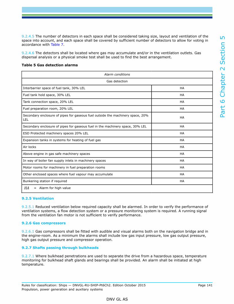
Part
6 C
hapt
er 2
Sec
tion
5
Rules for classification: Ships — DNVGL-RU-SHIP-Pt6Ch2. Edition October 2015 Page 141Propulsion, power generation and auxiliary systems
DNV GL AS
9.2.4.5 The number of detectors in each space shall be considered taking size, layout and ventilation of thespace into account, and each space shall be covered by sufficient number of detectors to allow for voting inaccordance with Table 7.
9.2.4.6 The detectors shall be located where gas may accumulate and/or in the ventilation outlets. Gasdispersal analysis or a physical smoke test shall be used to find the best arrangement.
Table 5 Gas detection alarms
Alarm conditions
Gas detection
Interbarrier space of fuel tank, 30% LEL HA
Fuel tank hold space, 30% LEL HA
Tank connection space, 20% LEL HA
Fuel preparation room, 20% LEL HA
Secondary enclosure of pipes for gaseous fuel outside the machinery space, 20%LEL HA
Secondary enclosure of pipes for gaseous fuel in the machinery space, 30% LEL HA
ESD Protected machinery spaces 20% LEL HA
Expansion tanks in systems for heating of fuel gas HA
Air locks HA
Above engine in gas safe machinery spaces HA
In way of boiler fan supply inlets in machinery spaces HA
Motor rooms for machinery in fuel preparation rooms HA
Other enclosed spaces where fuel vapour may accumulate HA
Bunkering station if required HA
HA = Alarm for high value
9.2.5 Ventilation
9.2.5.1 Reduced ventilation below required capacity shall be alarmed. In order to verify the performance ofventilation systems, a flow detection system or a pressure monitoring system is required. A running signalfrom the ventilation fan motor is not sufficient to verify performance.
9.2.6 Gas compressors
9.2.6.1 Gas compressors shall be fitted with audible and visual alarms both on the navigation bridge and inthe engine-room. As a minimum the alarms shall include low gas input pressure, low gas output pressure,high gas output pressure and compressor operation.
9.2.7 Shafts passing through bulkheads
9.2.7.1 Where bulkhead penetrations are used to separate the drive from a hazardous space, temperaturemonitoring for bulkhead shaft glands and bearings shall be provided. An alarm shall be initiated at hightemperature.

Part
6 C
hapt
er 2
Sec
tion
5
Rules for classification: Ships — DNVGL-RU-SHIP-Pt6Ch2. Edition October 2015 Page 142Propulsion, power generation and auxiliary systems
DNV GL AS
Table 6 Monitoring of fuel installations
Alarm conditions Comment
Fuel containment system
Level in tank IL, IR, HA alarm at 95% of tank volume
IL, IR*, HA* alarm level below opening pressure ofrelief devicesTank pressure
LA* if vacuum protection is required
Submerged fuel pump, low level in tank LA dry running protection
Hold spaces and interbarrier spaces, pressure IR without open connection to theatmosphere
Fuel supply system
Fuel pump discharge lines, pressure IL, IR
Bunkering and vapour return lines, pressure IL
Gas compressor
Fuel gas inlet pressure LA*
Fuel gas outlet pressure LA*
Fuel gas outlet pressure HA*
Compressor operation A*
Bilge
Tank connection space, level in bilge well HA
Fuel preparation room, level in bilge well HA
Other spaces containing cryogenic systems, level in bilge well HA systems without secondary enclosures
Fuel heating
Heating medium temperature, at vaporizer outlet IR, LA
Loss of heating medium circulation A
Fuel supply, temperature IR, LA at the heat exchanger outlet
Ventilation
Reduced ventilation in ESD protected machinery space LA
Reduced ventilation in tank connection space LA
Reduced ventilation in fuel preparation room LA
Reduced ventilation in secondary enclosure of pipes forgaseous fuel LA
Other alarm conditions
Air lock, more than one door moved from closed position A local alarm on both sides of air lock,[3.4.2.1]

Part
6 C
hapt
er 2
Sec
tion
5
Rules for classification: Ships — DNVGL-RU-SHIP-Pt6Ch2. Edition October 2015 Page 143Propulsion, power generation and auxiliary systems
DNV GL AS
Alarm conditions Comment
Air lock, door open at loss of ventilation A [3 4.2.5]
Malfunction of double-block-and-bleed valves A [5.1.6.9] and [5.4.1.3]
Temperature monitoring bulkhead shaft glands and bearings IR, HA
Low oxygen alarm in N2 spaces A local alarm, [5.4.2.1]
* also to be indicated on bridgeIL = Local indication (presentation of values)IR = Remote indication (presentation of values) in engine control room or control location for bunkering when
specifiedA = Alarm activated for logical valueLA = Alarm for low valueHA = Alarm for high value
9.3 Fuel installation safety9.3.1 Tank overflow protection
9.3.1.1 A level sensing device shall be provided which automatically actuates the shut-off of the flow of fuelto the tank in a manner which will both, avoid excessive liquid pressure in the loading line and prevent thetank from becoming liquid full. This level sensing device shall be independent of the level sensing devicesrequired by [9.2.1.1] and [9.2.1.2].
9.3.1.2 For tanks where submerged fuel pump motors are installed, arrangements shall be made toautomatically shut down the motors in the event of low-low liquid level. The automatic shutdown may beaccomplished by sensing low pump discharge pressure, low motor current, or low liquid level. This shutdownshall be alarmed.
9.3.2 Safety upon gas detection
9.3.2.1 Gas detection in a tank connection space when two detectors indicate a vapour concentration of40% LEL shall result in automatic closing of all valves required to isolate the leakage. This will in most casesrequire that all tank valves shall close automatically. Depending on the system arrangement, it may also benecessary to close other valves. Any pump for cryogenic liquids located in the tank connection space shallalso be automatically shut down.
9.3.2.2 Gas detection in a fuel preparation room when two detectors indicate a vapour concentration of 40%LEL shall result in automatic closing of all valves required to isolate the leakage. This will require that valvesin the fuel system supplying liquefied or gaseous fuel to the fuel preparation room shall close automatically.Depending on the system arrangement, it may also be necessary to close other valves. All machinery in thespace, such as compressors and pumps, shall be automatically shut down.
9.3.2.3 Gas detection in the secondary enclosure of pipes for gaseous fuel outside the machinery space,when two detectors indicate a vapour concentration of 40% LEL, shall result in automatic closing of all valvesrequired to isolate the leakage. Depending on the system arrangement, this may require automatic closing ofthe tank valve, fuel preparation room valves and the master gas fuel valve.
9.3.2.4 Gas detection in the secondary enclosure of pipes for gaseous fuel in a gas safe machinery space,when two detectors indicate a vapour concentration of 60% LEL, shall result in automatic closing of allvalves required to isolate the leakage. This will require automatic closing of the master gas fuel valve andthe double-block-and-bleed valves, and automatic opening of vent valve in fuel supply system between

Part
6 C
hapt
er 2
Sec
tion
5
Rules for classification: Ships — DNVGL-RU-SHIP-Pt6Ch2. Edition October 2015 Page 144Propulsion, power generation and auxiliary systems
DNV GL AS
these valves. The pipe between the double block and bleed valve and the gas injection valves shall also beautomatically vented.
9.3.2.5 Gas detection in ESD protected machinery spaces, when two detectors indicate a vapourconcentration of 40% LEL, shall result in automatic closing of all valves required to isolate the leakagewithout delay. This will require automatic closing of the master gas fuel valve and the double-block-and-bleedvalves, and automatic opening of vent valve in fuel supply system between these valves. In addition, thesafety system shall automatically shut down the oil fuel supply for dual fuel engines and de-energize all non-explosion protected equipment or installations in the machinery spaces.The isolation of ignition sources shall be performed by the gas safety system via dedicated signals to therelevant electrical circuit breakers.
9.3.3 Safety upon cryogenic leakage detection
9.3.3.1 Low temperature detection in bilge wells of tank connection spaces, fuel preparation rooms or otherspaces containing cryogenic systems without secondary enclosures shall result in automatic closing of allvalves necessary to isolate the leakage.
9.3.3.2 Piping in the fuel system containing cryogenic liquids shall be provided with means for detection ofleakages into the secondary enclosure. Detection of leakages shall result in automatic closing of all valvesrequired to isolate the leakage. Leakage detection in the bunkering line shall immediately result in automaticclosing of the bunkering valve.
9.3.4 Safety fuel heating
9.3.4.1 Loss of heating medium circulation in the fuel vaporizer shall lead to automatic isolation of supplyof cryogenic fuel to the vaporiser, to prevent freezing of the heating medium. This implies that automaticclosing of tank valves in fuel systems connected to the vaporizer, and automatic stop of liquefied gas pumpsis required.
9.3.4.2 The heated fuel in supply lines to consumers shall be provided with temperature sensors at the heatexchanger outlet. Detection of low-low temperature shall result in automatic closing of all valves required tostop the fuel supply to the vaporizer.
9.3.5 Safety upon loss of ventilation
9.3.5.1 Loss of ventilation in ESD protected machinery spaces shall result in isolation of all fuel supply to themachinery space. This will require automatic closing of the master gas fuel valve and the double-block-and-bleed valves, and automatic opening of vent valve in fuel supply system between these valves.
9.3.5.2 Loss of ventilation in tank connection spaces shall result in automatic closing of all valves requiredto isolate the fuel system from the tank. This will require that all tank valves shall close automatically, andautomatic stop of liquefied gas pumps.
9.3.5.3 Loss of ventilation in a fuel preparation room shall result in automatic closing of all valves requiredto isolate the fuel system from the fuel preparation room. This will require that valves in the fuel system,supplying liquefied or gaseous fuel to the fuel preparation room, shall close automatically. All machinery inthe space, like compressors and pumps, shall be automatically shut down.
9.3.5.4 Loss of ventilation in secondary enclosure of pipes for gaseous fuel in the machinery space shallresult in automatic closing of all valves required to isolate the affected fuel system from the fuel source.This will require automatic closing of the master gas fuel valve and the double-block-and-bleed valves, andautomatic opening of vent valve in fuel supply system between these valves.
9.3.5.5 Loss of ventilation in the secondary enclosure of pipes for gaseous fuel outside the machinery spaceshall result in automatic closing of all valves required to isolate the affected fuel system from the fuel source.

Part
6 C
hapt
er 2
Sec
tion
5
Rules for classification: Ships — DNVGL-RU-SHIP-Pt6Ch2. Edition October 2015 Page 145Propulsion, power generation and auxiliary systems
DNV GL AS
Depending on the system arrangement, this may require automatic closing of the tank valve, fuel preparationroom valves and the master gas fuel valve.
9.3.5.6 Loss of ventilation in a non-hazardous space with air lock entrance from hazardous area on opendeck, or loss of ventilation in hazardous space with air lock entrance from a safe space, shall lead toautomatic shutdown of electrical equipment not certified for operation in zone 1 in the non-hazardous space.
9.3.6 Safety upon rupture detection
9.3.6.1 Each gas supply line entering an ESD protected machinery space, and each gas supply line to high-pressure installations, shall be provided with means for rapid detection of a rupture in the gas line in themachinery space. When a pipe rupture is detected, the gas supply shall be isolated from the machinery spaceby automatically closing the shut-off valve located outside the machinery space.
9.3.7 Manual shutdown push buttons
9.3.7.1 Means of manual emergency shutdown of fuel supply to the engine room shall be provided at safelocations on escape routes inside a machinery space containing a gas consumer, in the engine control room,outside the machinery space, and from the navigation bridge. The activation device shall be arranged as aphysical button, duly marked and protected against inadvertent operation. The manual shutdown shall behandled by the gas safety system, and be arranged with loop monitoring.
9.3.7.2 Closing of the bunkering shutdown valve shall be possible from the control location for bunkering.
9.3.8 Safety actions
9.3.8.1 The requirements in [9.3.1] to [9.3.7] and Table 7 specify fuel installation safety actions required tolimit the consequences of system failures.
9.3.8.2 Safety actions additional to the ones required by Table 7 may be required for unconventional orcomplex fuel installations.
Table 7 Gas safety functions
Automatic safety action with corresponding alarm
ConditionsAlarm
Shutdownof
Tank valves
Shutdownof fuel
preparationroomvalves
Shutdownof Mastergas fuelvalve1)
Shutdownof Bunkerconnection
valve
Isolateignition
sources inthe space
Signal to othercontrol/safetysystems for
additional action
Tank safety
bunkering HA XLevel in tank,overfill transfer HA X
Submerged fuel pump, low-low level in tank LA Stop fuel pumps
Gas detection
Tank connection space, 2 x40% LEL HA X Stop machinery
in the space
Fuel preparation room, 2 x40% LEL HA X Stop machinery
in the space

Part
6 C
hapt
er 2
Sec
tion
5
Rules for classification: Ships — DNVGL-RU-SHIP-Pt6Ch2. Edition October 2015 Page 146Propulsion, power generation and auxiliary systems
DNV GL AS
Automatic safety action with corresponding alarm
ConditionsAlarm
Shutdownof
Tank valves
Shutdownof fuel
preparationroomvalves
Shutdownof Mastergas fuelvalve1)
Shutdownof Bunkerconnection
valve
Isolateignition
sources inthe space
Signal to othercontrol/safetysystems for
additional action
Secondary enclosure of pipesfor gaseous fuel outside themachinery space, 2x 40% LEL
HA X X X
Open vent valvebetween mastergas valve andDDB valves.
Secondary enclosure ofpipes for gaseous fuel in themachinery space, 2x 60% LEL
HA X
Open vent valvebetween mastergas valve andDDB valves.
ESD Protected machineryspaces 2 x 40% LEL HA X X
Open vent valvebetween mastergas valve andDDB valves.
Cryogenic liquid leakagedetection
Tank connection space,temperature in bilge well LA X
Fuel preparation room,temperature in bilge well LA X
Leakage detection insecondary enclosure of pipesfor cryogenic liquids2)
A X X
Leakage detection bunkeringline A3) X
Fuel heating
Loss of heating mediumcirculation A X X Stop fuel pumps
Fuel supply, temperature LA X X X
Stop fuel pumpsOpen vent valvebetween mastergas valve andDDB valves.
Ventilation
ESD protected machinery, lossof ventilation A X
Open vent valvebetween mastergas valve andDDB valves.
Tank connection space, loss ofventilation A X Stop fuel pumps
in the space

Part
6 C
hapt
er 2
Sec
tion
5
Rules for classification: Ships — DNVGL-RU-SHIP-Pt6Ch2. Edition October 2015 Page 147Propulsion, power generation and auxiliary systems
DNV GL AS
Automatic safety action with corresponding alarm
ConditionsAlarm
Shutdownof
Tank valves
Shutdownof fuel
preparationroomvalves
Shutdownof Mastergas fuelvalve1)
Shutdownof Bunkerconnection
valve
Isolateignition
sources inthe space
Signal to othercontrol/safetysystems for
additional action
Fuel preparation room, loss ofventilation A X Stop machinery
in the space
Secondary enclosure of pipesfor gaseous fuel outside themachinery space, loss ofventilation
A X X X
Open vent valvebetween mastergas valve andDDB valves.
Secondary enclosure ofpipes for gaseous fuel in themachinery space , loss ofventilation
A X
Open vent valvebetween mastergas valve andDDB valves.
Loss of ventilation inhazardous space with air lockentrance from a safe space
A X
Loss of ventilation in non-hazardous space with air lockentrance from hazardous areaon open deck
A X
Rupture detection of gaspipe
Pipe in ESD protectedmachinery space A X
Open vent valvebetween mastergas valve andDDB valves.
High pressure pipe in gas safemachinery space A X
Open vent valvebetween mastergas valve andDDB valves.
Manual shutdown buttons
Emergency shutdown ofsupply to the machinery space X
Open vent valvebetween mastergas valve andDDB valves.
Emergency shutdown ofbunkering X

Part
6 C
hapt
er 2
Sec
tion
5
Rules for classification: Ships — DNVGL-RU-SHIP-Pt6Ch2. Edition October 2015 Page 148Propulsion, power generation and auxiliary systems
DNV GL AS
Automatic safety action with corresponding alarm
ConditionsAlarm
Shutdownof
Tank valves
Shutdownof fuel
preparationroomvalves
Shutdownof Mastergas fuelvalve1)
Shutdownof Bunkerconnection
valve
Isolateignition
sources inthe space
Signal to othercontrol/safetysystems for
additional action
1) upon closure of master gas fuel valve, a signal shall be sent to the gas consumers safety system to shut down thedouble block and bleed valves.
2) all valves required to isolate the leakage shall close3) alarm also to be indicated in the bunkering control locationA = Alarm activated for logical valueLA = Alarm for low valueHA = Alarm for high value
10 Gas turbines and boilers
10.1 Gas fuelled boiler installations10.1.1 General
10.1.1.1 Boiler plants built for gas operation shall satisfy the requirements as given in Pt.4 Ch.7 and shall inaddition satisfy the requirements in this section.
10.1.1.2 Alarm and safety systems shall comply with the requirements in Pt.4 Ch.9 and shall in additionsatisfy the requirements in this section.
10.1.2 Requirements for gas fuelled boilers
10.1.2.1 Each boiler shall have a dedicated forced draught system. A crossover between boiler force draughtsystems may be fitted for emergency use, providing that any relevant safety functions are maintained.
10.1.2.2 Combustion chambers and uptakes of boilers shall be designed to prevent any accumulation ofgaseous fuel.
10.1.2.3 Burners shall be designed to maintain stable combustion under all firing conditions.
10.1.2.4 On main/propulsion boilers an automatic system shall be provided to change from gas fuel operationto oil fuel operation without interruption of boiler firing.
10.1.2.5 Gas nozzles and the burner control system shall be configured such that gas fuel can only be ignitedby an established oil fuel flame, unless the boiler and combustion equipment is designed and approved bythe Society to light on gas fuel.
10.1.2.6 There shall be arrangements to ensure that gas fuel flow to the burner is automatically cut offunless satisfactory ignition has been established and maintained.
10.1.2.7 On the pipe of each gas burner, a manually operated shut-off valve shall be fitted.
10.1.2.8 Provisions shall be made for automatically purging the gas supply piping to the burners, by meansof an inert gas, after the extinguishing of these burners.

Part
6 C
hapt
er 2
Sec
tion
5
Rules for classification: Ships — DNVGL-RU-SHIP-Pt6Ch2. Edition October 2015 Page 149Propulsion, power generation and auxiliary systems
DNV GL AS
10.1.2.9 The automatic fuel changeover system required by [10.1.2.4] shall be monitored with alarms toensure continuous availability.
10.1.2.10 Arrangements shall be made that, in case of flame failure of all operating burners, the combustionchambers of the boilers are automatically purged before relighting.
10.1.2.11 Arrangements shall be made to enable the boilers purging sequence to be manually activated.
10.2 Gas fuelled turbines10.2.1 GeneralGas turbines shall comply with the requirements in Pt.4 Ch.3 Sec.2.
10.2.2 Gas turbine arrangement
10.2.2.1 Gas turbines shall be fitted in gas-tight enclosures which are arranged in accordance with therequirements for ESD protected machinery spaces.
10.2.2.2 For gas turbines requiring a supply of gas with pressures above 10 bar, gas piping shall be protectedwith a secondary enclosure in accordance with the requirements in [5.1.5] to the extent possible.
10.2.2.3 Ventilation for the enclosure shall be as outlined in in these Rules for ESD protected machineryspaces, but shall in addition be arranged with 2 x 100% capacity fans from different electrical circuits.
10.2.2.4 Gas detection systems, disconnection and shut down functions shall be as outlined for ESDprotected machinery spaces.
10.2.2.5 For other than single fuel gas turbines, an automatic system shall be fitted to change over easilyand quickly from fuel gas operation to fuel oil operation and vice-versa with minimum fluctuation of theengine power.
10.2.2.6 Means shall be provided to monitor and detect poor combustion that may lead to unburnt fuel gas inthe exhaust system during operation. In the event that it is detected, the fuel gas supply shall be shut down.
10.2.2.7 Unless designed with the strength to withstand the worst case over-pressure due to ignited gasleaks, pressure relief systems shall be suitably designed and fitted to the exhaust system. Pressure reliefsystems within the exhaust uptakes shall be lead to a safe location, away from personnel.
10.2.2.8 Each turbine shall be fitted with an automatic shutdown device for high exhaust temperatures.
11 Manufacture, workmanship and testing
11.1 Fuel containment system11.1.1 Welding, post-weld heat treatment and NDTWelding, post-weld heat treatment and non-destructive testing shall be in accordance with the rules in Pt.5Ch.7 Sec.6 [5] and Pt.5 Ch.7 Sec.6 [6].
11.1.2 TestingFuel containment system testing shall be in accordance with Pt.5 Ch.7 Sec.4 [5.2.3] and Pt.5 Ch.7 Sec.4[5.2.4].

Part
6 C
hapt
er 2
Sec
tion
5
Rules for classification: Ships — DNVGL-RU-SHIP-Pt6Ch2. Edition October 2015 Page 150Propulsion, power generation and auxiliary systems
DNV GL AS
11.2 Fuel piping systems11.2.1 Piping fabrication and joining detailsThe requirements apply to piping that contains fuel in gaseous and liquefied state.The piping system shall be joined by welding with a minimum of flange connections. Gaskets shall be of atype designed to prevent blow-out.
11.2.1.1 The following types of connections may be considered for direct connection of pipe lengths (withoutflanges):
1) Butt-welded joints with complete penetration at the root may be used in all applications. For designtemperatures colder than -10°C, butt welds shall be either double welded or equivalent to a doublewelded butt joint. This may be accomplished by use of a backing ring, consumable insert or inert gasback-up on the first pass. For design pressures in excess of 10 bar and design temperatures of minus10°C or colder, backing rings shall be removed.
2) Slip-on welded joints with sleeves and related welding, having dimensions in accordance with recognizedstandards, shall only be used for instrument lines and open-ended lines with an external diameter of 50mm or less and design temperatures not colder than minus 55°C.
3) Screwed couplings complying with recognized standards shall only be used for accessory lines andinstrumentation lines with external diameters of 25 mm or less.
11.2.1.2 Flanges in fuel piping shall be of the welding neck, slip-on or socket welding type. For all piping(except open ended lines), the following restrictions apply:
1) For design temperatures < -55°C only welding neck flanges shall be used.2) For design pressure above 10 bar, only welding neck flanges shall be used.3) For design temperatures < -10°C slip-on flanges shall not be used in nominal sizes above 100 mm and
socket welding flanges shall not be used in nominal sizes above 50 mm.
11.2.1.3 Flanges in secondary enclosures for fuel piping shall be of the welding neck, slip-on or socketwelding type.
11.2.2 Welding, post-weld heat treatment and NDT
11.2.2.1 Welding of fuel piping shall be carried out in accordance with Pt.5 Ch.7 Sec.6 [5].
11.2.2.2 Post-weld heat treatment shall be required for all butt welds of pipes made with carbon, carbon-manganese and low alloy steels. The Society may waive the regulations for thermal stress relieving of pipeswith wall thickness less than 10 mm in relation to the design temperature and pressure of the piping systemconcerned.
11.2.2.3 In addition to normal controls before and during the welding, and to the visual inspection of thefinished welds, as necessary for proving that the welding has been carried out correctly and according to theregulations in this paragraph, the following tests shall be required:
1) 100% radiographic or ultrasonic inspection of butt-welded joints for piping systems with;
— design temperatures colder than –10°C; or— design pressure greater than 10 bar; or— gas supply pipes in ESD protected machinery spaces; or— inside diameters of more than 75 mm; or— wall thicknesses greater than 10 mm.
2) When such butt welded joints of piping sections are made by automatic welding procedures approvedby the Society, then a progressive reduction in the extent of radiographic or ultrasonic inspection can beagreed, but in no case to less than 10% of each joint. If defects are revealed, the extent of examinationshall be increased to 100% and shall include inspection of previously accepted welds. This approval can

Part
6 C
hapt
er 2
Sec
tion
5
Rules for classification: Ships — DNVGL-RU-SHIP-Pt6Ch2. Edition October 2015 Page 151Propulsion, power generation and auxiliary systems
DNV GL AS
only be granted if well-documented quality assurance procedures and records are available to assess theability of the manufacturer to produce satisfactory welds consistently.
3) The radiographic or ultrasonic inspection regulation may be reduced to 10% for butt-welded joints in theouter pipe of double-walled fuel piping.
4) For other butt-welded joints of pipes, spot radiographic or ultrasonic inspection or other non-destructivetests shall be carried out, depending upon service, position and materials. In general, at least 10% ofbutt-welded joints of pipes shall be subjected to radiographic or ultrasonic inspection.
11.2.2.4 The radiographs shall be assessed according to ISO 10675 and shall at least meet the criteria forlevel 2 on general areas and level 1 on critical areas, as given in Pt.2 Ch.4 Sec.7 [5.1].
11.2.3 Testing
11.2.3.1 The requirements for testing in this section apply to gas piping inside and outside the gas tanks.However, relaxation from these requirements for piping inside gas tanks and open ended piping may beaccepted by the Society.
11.2.3.2 After assembly, all fuel gas piping shall be subjected to a hydrostatic test to at least 1.5 timesthe design pressure. However, when piping systems or parts of systems are completely manufactured andequipped with all fittings, the hydrostatic test may be conducted prior to installation onboard the ship. Jointswelded onboard shall be hydrostatically tested to at least 1.5 times the design pressure
11.2.3.3 After assembly on board, the fuel piping system shall be subjected to a leak test using air, or othersuitable medium to a pressure depending on the leak detection method applied.
11.2.3.4 If the secondary enclosure of the gas piping contains high-pressure pipes the secondary enclosureshall be pressure tested to the expected maximum pressure at pipe rupture, but minimum 10 bar. Secondaryenclosures for low pressure gas piping shall be tightness tested.
11.2.3.5 All piping systems, including valves, fittings and associated equipment for handling fuel or vapours,shall be function tested under normal operating conditions.
11.3 Valves11.3.1 Testing
11.3.1.1 Each type of valve shall be tested as given in Pt.5 Ch.7 Sec.5 [13.1].
11.4 Expansion bellows11.4.1 Testing
11.4.1.1 Expansion bellows intended for use in fuel systems shall be prototype tested as given in Pt.5 Ch.7Sec.5 [13.2].
11.5 Pumps11.5.1 Testing
11.5.1.1 Pumps shall be tested in accordance with Pt.5 Ch.7 Sec.5 [13.5]
Part
6 C
hapt
er 2
Sec
tion
5
Rules for classification: Ships — DNVGL-RU-SHIP-Pt6Ch2. Edition October 2015 Page 152Propulsion, power generation and auxiliary systems
DNV GL AS
11.6 Shutdown valves in liquefied gas fuel piping systems11.6.1 Testing
11.6.1.1 The closing characteristics of shutdown valves in liquefied gas fuel piping systems operated bythe safety system shall be tested to demonstrate compliance with [5.1.6.14]. The shutdown valves withactuators shall be function tested when the valve is subjected to full working pressure. The testing may becarried out onboard after installation.

Part
6 C
hapt
er 2
Sec
tion
6
Rules for classification: Ships — DNVGL-RU-SHIP-Pt6Ch2. Edition October 2015 Page 153Propulsion, power generation and auxiliary systems
DNV GL AS
SECTION 6 LOW FLASHPOINT LIQUID FUELLED ENGINES -LFL FUELLED
1 General
1.1 IntroductionThe additional class notation LFL fuelled provides criteria for the arrangement and installation of machineryfor propulsion and auxiliary purposes, using low flash point liquids (LFLs) as fuel, which will have anequivalent level of integrity in terms of safety and availability as that which can be achieved with new andcomparable conventional oil-fuelled main and auxiliary machinery.
1.2 ScopeThe scope for additional class notation LFL fuelled includes requirements from the vessel's LFL fuelbunkering connection up to and including the consumers. The rules in this section have requirementsfor arrangement and location of fuel tanks and all spaces with fuel piping and installations, includingrequirements for entrances to such spaces. Hazardous areas and spaces due to the fuel installations aredefined. Requirements for control, monitoring and safety systems for the fuel installations are included,also additional monitoring requirements for engines and pumps. For tank design and piping detail, designreference is in general made to Pt.5 Ch.6. Requirements for manufacture, workmanship and testing areincluded, mainly referring to details given in Pt.5 Ch.6. Bunkering procedures are required to be approved,however, bunkering processes are not part of the scope for this section of the rules.
1.3 ApplicationThe additional class notation LFL fuelled is applicable for installations where methyl alcohol or ethyl alcoholis used as fuel. Other liquid fuels with low flash point may be accepted for use after special considerations.The use of low flash point liquid fuel is not currently covered by international conventions, and suchinstallations will need additional acceptance by flag authorities. Methyl alcohol is a chemical within theformula CH3OH, also known as methanol. Ethyl alcohol is a chemical within the formula C2H5OH, also knownas ethanol. If other low flash point fuel types are used, then special consideration will need to be taken, andadditional requirements may be relevant. Special applications depending on ship type are covered in [11].Vessels built in accordance with the requirements in this section may be assigned the class notation LFLfuelled.
1.4 References1.4.1 Terminology and definitions
Table 1 Definitions – General terms
Term Definition
accommodation spacesare those spaces used for public spaces, corridors, lavatories, cabins, offices, hospitals,cinemas, game and hobby rooms, barber shops, pantries containing no cookingappliances and similar spaces.

Part
6 C
hapt
er 2
Sec
tion
6
Rules for classification: Ships — DNVGL-RU-SHIP-Pt6Ch2. Edition October 2015 Page 154Propulsion, power generation and auxiliary systems
DNV GL AS
Term Definition
control stations
are those spaces in which the ship's radio or main navigating equipment or theemergency source of power is located or where the fire recording or fire controlequipment is centralized. Spaces where the fire recording or fire control equipment iscentralized are also considered to be a fire control station.
Guidance note:This does not include special fire control equipment that can be most practically located in thecargo area (if the vessel is a cargo ship).
---e-n-d---of---g-u-i-d-a-n-c-e---n-o-t-e---
control systems are those systems providing control and monitoring for bunkering, LFL storage and LFLsupply to machinery.
dual fuel engines are in this context engines that can burn LFL fuel and fuel oil simultaneously and in awide variety of proportions, or can operate either on oil fuel or LFL.
enclosed hazardous space
means any space within which, in the absence of artificial ventilation, the ventilation willbe limited and any explosive atmosphere will not be dispersed naturally.
Guidance note:See also definition in IEC 60092-502:1999.
---e-n-d---of---g-u-i-d-a-n-c-e---n-o-t-e---
engine room means any machinery spaces containing LFL fuelled engines.
fuel can in this section be read as LFL fuel.
fuel containment system is the arrangement for the storage of fuel, including cofferdams around storage tanks.
hazardous area
is an area in which an explosive gas atmosphere is or may be expected to be present,in quantities such as to require special precautions for the construction, installation anduse of electrical apparatus. Hazardous areas are divided into Zone 0, 1 and 2 as definedbelow and according to the area classification specified in [5.2].
Zone0 = Area in which an explosive gas atmosphere is present continuously or is
present for long periods.Zone1 = Area in which an explosive gas atmosphere is likely to occur in normal
operation.
Zone2 =
Area in which an explosive gas atmosphere is not likely to occur in normaloperation and, if it does occur, is likely to do so only infrequently and will existfor a short period only.
Guidance note:The definition of hazardous area is only related to the risk of explosion. In this context, health,safety and environmental issues, i.e. toxicity, is not considered.
---e-n-d---of---g-u-i-d-a-n-c-e---n-o-t-e---
high risk fire areas high risk fire areas are cargo areas for carriage of dangerous goods and cargo decks forcars with fuel in the tanks.
machinery spaces
are machinery spaces of category A and other spaces containing propulsion machinery,boilers, oil fuel units, steam and internal combustion engines, generators and majorelectrical machinery, oil filling stations, refrigerating, stabilizing, ventilation and airconditioning machinery, and similar spaces, and trunks to such spaces.
non-hazardous area is an area not considered to be hazardous, i.e. gas safe, provided certain conditions arebeing met.

Part
6 C
hapt
er 2
Sec
tion
6
Rules for classification: Ships — DNVGL-RU-SHIP-Pt6Ch2. Edition October 2015 Page 155Propulsion, power generation and auxiliary systems
DNV GL AS
Term Definition
open deckmeans a weather deck or a deck that is open at one or both ends and equipped withadequate natural ventilation that is effective over the entire length of the deck throughpermanent openings distributed in the side panels or in the deck above.
pump room is in this section defined as any space outside the fuel tank that contains LFL fuel pumps,both transfer pumps and booster pumps.
safety systems are the safety systems for bunkering, LFL storage and LFL supply to machinery.
service spacesare spaces outside the cargo area used for galleys, pantries containing cookingappliances, lockers, mail and specie rooms, store rooms, workshops other than thoseforming part of the machinery spaces and similar spaces and trunks to such spaces.
low flashpoint liquid (LFL) is a liquid with a vapour pressure of less than 2.8 bar absolute at a temperature of38.7°C and having a flashpoint less than 60°C.
1.4.2 Abbreviations and symbolsLEL = Lower explosion limit.LFL = Low Flashpoint Liquid. Low Flashpoint Liquid is a liquid with a flashpoint below 60°C.
1.5 Procedural requirements1.5.1 Documentation requirements
1.5.1.1 Documentation shall be submitted as required by Table 2.
Table 2 Documentation required
Object Documentation type Additional description Info
Propulsionand steeringarrangements,general
Z050 – Design PhilosophyIncluding information on the machinery configuration, engineroom arrangements, fuel arrangements, shut down philosophy,redundancy considerations etc.
FI
Z030 – Arrangement plan
Arrangement plan to be in profile and plan views including:
— Machinery and boiler spaces, accommodation, service andcontrol station spaces
— Fuel tanks and containment systems— Fuel pump rooms— Fuel bunkering pipes with shore connections— Tank hatches, ventilation pipes and any other openings to the
fuel tanks— Ventilating pipes, door and opening to fuel pump rooms, double
walled piping and other hazardous areas— Entrances, air inlets and openings to accommodation, service
and control station spaces— WT divisions
AP
Z253 - Test procedure forquay and sea trial
Including testing of safety shutdowns in accordance with the causeand effect diagram AP
LFL system
Z161 – Operation manual See [9] AP

Part
6 C
hapt
er 2
Sec
tion
6
Rules for classification: Ships — DNVGL-RU-SHIP-Pt6Ch2. Edition October 2015 Page 156Propulsion, power generation and auxiliary systems
DNV GL AS
Object Documentation type Additional description Info
C030 Detailed drawing
Including:
— tanks— supports and stays— insulation— tank hatches, pipes and any opening to the tanks.— secondary barriers
AP
C040 Design analysis
Independent tanks:
— specification of design loads and structural analysis of fueltanks.
Integral tanks:
— covered by hull structures analyses.
AP
S010 Piping Diagram (PD) Purging and gas freeing system including safety relief valves andassociated piping AP
Z030 Arrangement plan Overview of tanks with all tank connections and tank connectionspace FI
LFL tanks
Z110 - Data sheet Pressure/vacuum relief valves and associated piping FI
I200 Control and monitoringsystem documentation
— Control and monitoring of fuel system, including:— tank level monitoring— tank system control and monitoring— bunkering control— fuel supply control and monitoring.
AP
I200 Control and monitoringsystem documentation Safety system covering the requirements given Table 5. AP
I260 Field instrumentsperiodic test plan AP
LFL controlandmonitoringsystem
G130 Cause and effectdiagram
— Covering the safety function given by Table 5. Includinginterfaces to other safety and control systems.
AP
S010 Piping diagram Including ventilation lines for pressure/vacuum relief valves orsimilar piping, and ducts for fuel pipes. AP
S060 Pipe routing sketch FI
S090 Specification of pipes,valves, flanges and fittings Including expansion elements. FI
LFL pipingsystem
Z100 Specification Electrical bonding of piping AP
LFL drip trays Z030 Arrangement plan Fuel system drip trays and coamings where leakages may beanticipated AP
LFL Coolingsystem S010 Piping diagram AP
LFL Heatingsystem S010 Piping diagram AP

Part
6 C
hapt
er 2
Sec
tion
6
Rules for classification: Ships — DNVGL-RU-SHIP-Pt6Ch2. Edition October 2015 Page 157Propulsion, power generation and auxiliary systems
DNV GL AS
Object Documentation type Additional description Info
Hazardousareasclassification
G080 Hazardous areaclassification drawing AP
Air lockarrangement Z030 Arrangement plan Location and construction details, including alarm equipment. AP
S012 Ducting diagramFor spaces containing LFL installations, like LFL pipe ducts andpump rooms. Including capacity and location of fans and theirmotors.
APVentilationsystemsfor gas fuelsystemspaces C030 Detailed drawing Rotating parts and casings for fans and portable ventilators. AP
Ventilationcontrol andmonitoringsystem
I200 Control and monitoring Including detection of ventilation function, safety actions andsequences, arrangement of powering of fans etc AP
Z030 Arrangement planAn approved hazardous area classification drawing where locationof electric equipment is added (except battery room, paint storesand gas bottle store)
FI
E090 Table of Ex-installation Based on approved area classification AP
Explosion(Ex)protection
Z163 - Maintenance manual Electrical equipment in hazardous areas FI
I200 Control and monitoringsystem documentation Including fixed liquid leakage detection system APHydrocarbon
gas detectionand alarmsystem, fixed Z030 Arrangement plan Detectors, call points and alarm devices. Including fixed liquid
leakage detection AP
Structural fireprotectionarrangements
G060 Structural fireprotection drawing AP
Bunkeringstation fireextinguishingsystem
G200 Fixed fireextinguishing systemdocumentation
Not applicable for tankers AP
I200 Control and monitoringsystem documentation APFire detection
and alarmsystem Z030 Arrangement plan AP
Fireextinguishingequipment,mobile
Z030 Arrangement plan At bunkering stations and entrance to engine rooms. AP
Inert gas/nitrogensystem
S010 Piping diagram (PD) AP
Inert gascontrol andmonitoringsystem
I200 Control and monitoringsystem documentation AP

Part
6 C
hapt
er 2
Sec
tion
6
Rules for classification: Ships — DNVGL-RU-SHIP-Pt6Ch2. Edition October 2015 Page 158Propulsion, power generation and auxiliary systems
DNV GL AS
Object Documentation type Additional description Info
AP = For approvalFI = For informationACO = As carried outL = Local handlingR = On requestTA = Covered by type approvalVS = Vessel specific
1.5.1.2 For general requirements to documentation, including definition of the Info codes, see Pt.1 Ch.3Sec.2.
1.5.1.3 For a full definition of the documentation types, see Pt.1 Ch.3 Sec.3.
1.5.1.4 An operation manual as described in [9] shall be kept on board.
1.5.1.5 A plan for periodic test of all field instruments specified in these rules shall be kept onboard. The planshall include test intervals, description of how to perform the tests and description of what to observe duringthe tests. Test intervals for shutdown inputs and outputs (as required by Table 5) shall not exceed 6 months.For other signals the test intervals shall not exceed 12 months. The plan shall be included in the vessel’smaintenance plan required by Pt.7.
Guidance note:See Sec.2 [1.4] for information about plan for periodic test.
---e-n-d---of---g-u-i-d-a-n-c-e---n-o-t-e---
1.5.2 Certification requirements
1.5.2.1 Components in the LFL fuel system shall be certified according to Pt.4 Ch.6 as applicable for fuel oilsystems. Components in the nitrogen system shall be certified as specified in Pt.5 Ch.6 Sec.16. Engines shallbe certified according to Pt.4 Ch.3. For other items, see Table 2
1.5.2.2 For a definition of the certificate types, see Pt.1 Ch.3 Sec.5.
Table 3 Certification required
Object CertificateType Issued by Certification Standard* Additional description
PC SocietyCombustioncontrol systemfor LFL burningengines
TA Society
LFL control,monitoring andsafety system
PC Society
Major units of equipment associatedwith essential and important controland monitoring systems, shall beprovided with a product certificate unlessexemption is given in a Type ApprovalCertificate issued by the Society or thelogic is simple and the failure mechanismsare easily understood. Ref. Pt.4 Ch.9.

Part
6 C
hapt
er 2
Sec
tion
6
Rules for classification: Ships — DNVGL-RU-SHIP-Pt6Ch2. Edition October 2015 Page 159Propulsion, power generation and auxiliary systems
DNV GL AS
Object CertificateType Issued by Certification Standard* Additional description
PCElectric motorsand motorstarters TA
Society
Electric motors and motor-starters forthe LFL supply system and ventilationsystem are considered to be importantconsumers, and shall be certified inaccordance with Pt.4 Ch.8 Sec.1.
MC Society
PC ManufacturerPiping system
TR Society
As required in Pt.5 Ch.6 for cargo piping.
PC = Product certificateTA = Type approval certificateTR = Test Report
*Unless specified otherwise the certification standard is the rules
2 Materials
2.1 General2.1.1 General
2.1.1.1 Metallic materials are in general to be in accordance with the requirements in Pt.2.
2.1.1.2 Materials other than those covered by Pt.2 may be accepted subject to approval in each separatecase.
2.1.1.3 When selecting construction materials in detachable equipment units in tanks and cofferdams, dueconsideration should be paid to the contact spark-producing properties.
2.1.2 Fuel tanks
2.1.2.1 Materials for integral tanks and independent tanks shall be selected in accordance with ordinarypractice as given in Pt.3 Ch.3 Sec.1 for hull materials.
2.1.2.2 Materials for pressure vessels containing LFL shall be as given in Pt.2 Ch.2 Sec.3.
2.1.3 Fuel piping
2.1.3.1 Materials for fuel pipes shall be as given in Pt.2 Ch.2 Sec.5.
2.1.3.2 Materials in LFL piping systems shall be provided with documentation as required for cargo piping inaccordance with Pt.5 Ch.6.

Part
6 C
hapt
er 2
Sec
tion
6
Rules for classification: Ships — DNVGL-RU-SHIP-Pt6Ch2. Edition October 2015 Page 160Propulsion, power generation and auxiliary systems
DNV GL AS
3 Arrangement and design
3.1 General3.1.1 General
3.1.1.1 The propulsion and fuel supply system shall be so designed that the remaining power after anysafety actions required by Table 5 shall be sufficient to maintain propulsion, power generation and other mainfunctions as defined in Pt.1 Ch.1 Sec.1 [1.2].
3.1.1.2 Except for cargo area of tankers, all parts of the LFL fuel system shall be located in enclosures forphysically limiting the extent of gas hazardous areas. The enclosures shall be provided with means forautomatic leakage detection.
3.1.1.3 Drip trays shall be installed below all possible leakage points in the fuel system.
3.1.1.4 All fuel piping and tanks shall be electrically bonded to the ship's hull. Bonding straps across stainlesssteel flanges with bolts and nuts of stainless steel are not required. If carbon-manganese steel is not fittedwith bonding straps across the flanges, it shall be checked for electric bonding. The electrical bonding issufficient, when the electrical resistance between piping and the hull does not exceed 106 Ohm. LFL pipingcomponents which are not permanently connected to the hull by permanent piping connections, shall beelectrically bonded to the hull by special bonding straps.
Guidance note:The value of resistance 106 Ohm may be achieved without the use of bonding straps where LFL piping systems and equipment aredirectly, or via their supports, either welded or bolted to the hull of the ship. It will be generally necessary initially to achieve aresistance value below 106 Ohm, to allow for deterioration in service.
---e-n-d---of---g-u-i-d-a-n-c-e---n-o-t-e---
3.1.1.5 Bilge systems installed in areas with LFL fuel installations shall be segregated from other bilgesystems.
3.1.1.6 Redundancy requirements apply as follows:
— In case of dual fuel concept: Redundancy for active components as given in Pt.4 Ch.1 Sec.3 [2.3] appliesfor both oil fuel and LFL fuel systems. For the LFL fuel system redundancy type 3(see definition in Pt.4Ch.1 Sec.1 Table 1) may be considered if it can be demonstrated that activation time for R3 is achievable.
— In case of single fuel concept: Redundancy for active components as given in Pt.4 Ch.1 Sec.3 [2.3]applies. In addition all of the LFL fuel supply system including service tank shall be arranged withredundancy.
3.2 Fuel storage3.2.1 Location of fuel tanks
3.2.1.1 Fuel tanks shall not be located within machinery spaces or within accomodation spaces.
3.2.1.2 Minimum distance between the fuel tank and the ship's shell shall be at least 760 mm.
3.2.1.3 The spaces forward of the collision bulkhead (forepeak) and aft of the aftermost bulkhead (afterpeak)shall not be used as fuel tanks.

Part
6 C
hapt
er 2
Sec
tion
6
Rules for classification: Ships — DNVGL-RU-SHIP-Pt6Ch2. Edition October 2015 Page 161Propulsion, power generation and auxiliary systems
DNV GL AS
3.2.1.4 Each fuel service tank shall have a capacity sufficient for continuous rating of the propulsion plantand normal operating load at sea of the generator plant for a period of not less than 8 hours.
3.2.2 Segregation of fuel tanks
3.2.2.1 In ships other than tankers, integral fuel tanks for LFL shall be surrounded by cofferdams except thatthe fuel pump room is regarded as cofferdam in this context.
3.2.2.2 The cofferdams shall be arranged with vapour and liquid leakage detection and possibility for waterfilling upon detection of leakage. The water filling shall be through a system without permanent connectionsto water systems in non-hazardous areas. Emptying shall be done with a separate system. Bilge ejectorsserving hazardous spaces shall not be permanently connected to the drive water system.
3.2.3 Gas freeing, inerting and venting of fuel tanks
3.2.3.1 Fuel tanks shall be provided with an arrangement for inert gas purging and gas freeing.
3.2.3.2 Fuel tanks shall have a sufficient number of ventilation inlets and outlets to ensure complete gas-freeing. Outlets for ventilation and purging shall be fitted with flame screens of approved type, ref IMO MSC/Circ.677
3.2.3.3 The tanks shall have controlled venting, i.e. be fitted with pressure/vacuum relief valves. If p/vvalves are fitted to the end of the vent pipes they shall be of the high velocity type certified for enduranceburning in accordance with IMO MSC/Circ.677. If p/v valves are fitted in the ventline, the vent outlet shall befitted with a flame arrestor certified for endurance burning in accordance with IMO MSC/Circ.677.
3.2.3.4 Vent outlets from p/v valves and outlets for purging shall be led to open air and located so that thehazardous zone associated with the outlets does not conflict with ventilation inlets or outlets for gas safespaces or equipment representing sources of ignition.The venting system shall be connected to the highest point of each fuel tank and vent lines shall be self-draining under all normal operating conditions of list and trim.
3.2.3.5 Shut-off valves shall not be fitted above or below pressure/vacuum safety valves, but by-pass valvesmay be provided.
3.2.3.6 The venting system shall be designed with redundancy for the relief of full flow overpressure andvacuum. In lieu of duplicating p/v valves, pressure sensors fitted in each fuel tank, and connected to analarm system, may be accepted. The opening pressure of the vacuum relief valves is not to be lower than0.07 bar below atmospheric pressure.
3.2.3.7 Pressure/vacuum safety valves shall be located on open deck and shall be of a type which allows thefunctioning of the valve to be easily checked.
3.2.3.8 Intake openings of pressure/vacuum relief valves shall be located at least 1.5 m above weather deck,and shall be protected against the sea.
3.2.3.9 Fuel tank vent outlets shall be situated not less than 3 m above the deck or gangway if located within4 m from such gangways. The fuel tank vent outlets are also to be arranged at a distance of at least 10m from the nearest air intake or opening to accommodation and service spaces and ignition sources. Thevapour discharge shall be directed upwards in the form of unimpeded jets.
3.2.3.10 The vent system shall be sized, allowing for flame arrestors, if fitted, to permit filling at 125% of thedesign rate without overpressurizing the tank.
3.2.3.11 The arrangement for gas freeing fuel tanks shall be such as to minimize the hazards due to thedispersal of flammable vapours in the atmosphere and to flammable vapour mixtures in a fuel tank. The

Part
6 C
hapt
er 2
Sec
tion
6
Rules for classification: Ships — DNVGL-RU-SHIP-Pt6Ch2. Edition October 2015 Page 162Propulsion, power generation and auxiliary systems
DNV GL AS
ventilating system used for gas freeing of fuel tanks shall be used exclusively for ventilating purposes.Connection between fuel tank and pump room ventilation will not be accepted. Ventilation fans may be fixedor portable.
3.2.3.12 Gas freeing of fuel tanks shall be carried out in a way that flammable atmosphere in the tankis avoided, i.e. by purging tank with inert gas until gas content is below 2% before ventilation with air isstarted.Purging and gas freeing operations shall be carried out such that vapour is initially discharged through outletsat least 2 m above the deck level with a vertical efflux velocity of at least 20 m/s.
Guidance note:When the flammable vapour concentration at the outlets has been reduced to 30% of the lower flammable limit, gas freeing maythereafter be continued at deck level.
---e-n-d---of---g-u-i-d-a-n-c-e---n-o-t-e---
3.2.4 Fuel tanks on weather deck of tankers
3.2.4.1 LFL fuel tanks on open deck shall be protected against mechanical damage.
3.2.4.2 LFL deck tanks on open deck shall be surrounded by coamings.
3.2.4.3 Special considerations shall be taken to minimize any fire hazards adjacent to the fuel tanks onweather deck. Protection of the LFL fuel tanks from possible fires onboard may be subject to a fire safetyassessment in each particular case.
3.2.5 Portable fuel tanks
3.2.5.1 Fuel systems utilising portable storage tanks will be specially considered, and shall have equivalentsafety as permanent fuel tanks.
3.2.5.2 Portable fuel tanks shall be certified by the Society.
3.2.5.3 The tank support (container frame or truck chassis) shall be designed for the intended purpose.
3.2.5.4 Except for location on the tank deck of tankers, portable fuel tanks shall be located in a dedicatedspace.
3.2.5.5 The tank hold space shall be arranged in accordance with requirements for fuel pump rooms.
3.2.5.6 Portable fuel tanks shall be secured to the deck while connected to the ship systems. Thearrangement for supporting and fixing the tanks shall be designed for the maximum expected static anddynamic inclinations, as well as the maximum expected values of acceleration, taking into account the shipcharacteristics and the position of the tanks.
3.2.5.7 Connections to the ship piping systems shall be made by means of approved flexible hoses or othersuitable means designed to provide sufficient flexibility.
3.2.5.8 Arrangements shall be provided to limit the quantity of fuel spilled in case of inadvertentdisconnection or rupture of the non-permanent connections.
3.2.5.9 The pressure/vacuum relief system of portable tanks shall be connected to a fixed venting system.
3.2.5.10 Control and monitoring systems for portable fuel tanks shall be integrated in the ship's control andmonitoring system. Safety system for portable fuel tanks shall be integrated in the ship's gas safety system(e.g. shutdown systems for tank valves, leak/gas detection systems).

Part
6 C
hapt
er 2
Sec
tion
6
Rules for classification: Ships — DNVGL-RU-SHIP-Pt6Ch2. Edition October 2015 Page 163Propulsion, power generation and auxiliary systems
DNV GL AS
3.2.5.11 Safe access to tank connections for the purpose of inspection and maintenance shall be ensured.
3.3 Fuel transfer and supply3.3.1 Piping systems
3.3.1.1 The fuel system shall be entirely separate from all other piping systems on board.
3.3.1.2 The piping shall be located no less than 760 mm from the ship side.
3.3.1.3 All piping containing LFL shall be arranged for gas-freeing and inerting.
3.3.1.4 The fuel piping system shall be dimensioned as given in Pt.4 Ch.6 Sec.8. The design pressure p is themaximum working pressure to which the system may be subjected. The design pressure for fuel piping is asa minimum to be taken as 10 bar.
3.3.1.5 Filling lines to fuel tanks shall be so arranged that the generation of static electricity is reduced, e.g.by reducing the free fall into the tank to a minimum.
3.3.1.6 Fuel pipes shall be colour marked based on a recognized standard.Guidance note:See EN ISO 14726:2008 Ships and marine technology - Identification colours for the content of piping systems.
---e-n-d---of---g-u-i-d-a-n-c-e---n-o-t-e---
3.3.2 Protection of fuel transfer system
3.3.2.1 Fuel piping shall be protected against mechanical damage.Fuel pipes lead through ro-ro spaces on open deck shall be provided with guards or bollards to preventvehicle collision damage. Fuel pipes in other types of cargo areas with risk of damage from cargo operationsshall be similarly protected. Fuel pipes in double ducts in other areas are regarded as sufficiently protected.
3.3.2.2 All piping containing LFL that pass through enclosed spaces in the ship shall be enclosed in a pipethat is gas tight and water tight towards the surrounding spaces with the LFL contained in the inner pipe.Such double walled piping is not required in cofferdams surrounding fuel tanks, fuel pump rooms, fuel tankhold spaces or other hazardous fuel treatment spaces as the boundaries for these spaces will serve as asecond barrier.
3.3.2.3 Fuel piping shall not be lead through accommodation spaces, service spaces or control stations. Incases where fuel piping shall be led through accommodation spaces, the double walled fuel piping shall be ledthrough a dedicated duct. The duct shall be of substantial construction and be gas tight and water tight.
3.3.2.4 The annular space in the double walled fuel pipe shall have mechanical ventilation of underpressuretype with a capacity of minimum 30 air changes per hour. Ventilation inlets and outlets shall be located inopen air. The annular space shall be equipped with vapour and liquid leakage detection.
3.3.2.5 The outer pipe in the double walled fuel pipes shall be dimensioned for a design pressure not lessthan the maximum working pressure of the fuel pipes. As an alternative the calculated maximum built uppressure in the duct in the case of a pipe rupture may be used for dimensioning of the duct.
3.3.2.6 The annular space in the double walled fuel piping shall be segregated at the engine room bulkhead.This means that there shall be no common ducting between the engine room and other spaces.
3.3.2.7 There shall be no openings between the annular space in the double walled fuel piping and enclosedspaces in the ship.

Part
6 C
hapt
er 2
Sec
tion
6
Rules for classification: Ships — DNVGL-RU-SHIP-Pt6Ch2. Edition October 2015 Page 164Propulsion, power generation and auxiliary systems
DNV GL AS
Guidance note:Fuel valves in such spaces may be accessible through a bolted opening that is both gas tight and water tight when sealed.
---e-n-d---of---g-u-i-d-a-n-c-e---n-o-t-e---
3.3.2.8 The annular space in the double walled fuel piping shall be equipped with means for safe drainage.
3.3.3 Valves
3.3.3.1 LFL service tank inlets and outlets and storage tanks with outlets under static pressure shall beprovided with remotely operated shut-off valves located as close to the tank as possible. The tank valve shallautomatically cut off the LFL supply as given in Table 5.
3.3.3.2 Valves that are required to be operated during normal operation and which are not readily accessibleshall be remotely operated. Regarding automatic operation of tank valves, see Table 5.
3.3.3.3 The main supply lines for fuel to each engine room shall be equipped with automatically operatedmaster LFL fuel valves. The shut-off valve shall be situated outside the engine room. The master LFL fuelvalve is automatically to cut off the LFL supply to the engine room as given in Table 5.
3.3.3.4 The LFL fuel supply to each consumer shall be provided with a remote shut-off valve.
3.3.3.5 There shall be one manually operated shutdown valve in the LFL supply line to each engine to assuresafe isolation during maintenance on the engine.
3.3.3.6 All automatic and remotely operated valves shall be provided with indications for open and closedvalve positions at the location where the valves are remotely operated.
3.3.3.7 Valves shall fail to a safe position.Guidance note:“Fail to close” is generally considered to be the safe mode.
---e-n-d---of---g-u-i-d-a-n-c-e---n-o-t-e---
3.3.4 Pipe connections
3.3.4.1 Piping systems in fuel tanks and their cofferdams shall have no connections with piping systems inthe rest of the ship, apart from fuel pipes which shall be arranged as specified in other parts of this section.
3.3.4.2 Fuel piping shall not penetrate fuel tank boundaries below the top of the tank. However, penetrationsbelow the top of the tank may be accepted provided that a remotely operated shut-off valve is fitted withinthe fuel tank served. Where a fuel tank is adjacent to a pump room, the remotely operated stop valve maybe fitted on the fuel tank bulkhead on the pump room side.
3.3.4.3 Fuel piping system shall be installed with sufficient flexibility. Expansion bellows shall not be used.
3.3.5 LFL fuel pump rooms
3.3.5.1 Any pump room shall be located outside the engine room, be gas tight and water tight to surroundingenclosed spaces and vented to open air.
3.3.5.2 The pump room shall have separate mechanical ventilation of underpressure type with capacity of minimum30 air changes per hour.
3.3.5.3 The pump room shall be provided with leakage detection, both for gases and liquids.

Part
6 C
hapt
er 2
Sec
tion
6
Rules for classification: Ships — DNVGL-RU-SHIP-Pt6Ch2. Edition October 2015 Page 165Propulsion, power generation and auxiliary systems
DNV GL AS
3.3.5.4 LFL pump rooms shall be provided with a dedicated bilge system, operable from outside the pumproom. Bilge ejectors serving hazardous spaces shall not be permanently connected to the drive water system.The bilge system may have possibilities for discharge to a suitable cargo tank, slop tank or similar, howevertaking into account hazards related to incompatibility.
3.3.6 LFL fuel heating or cooling
3.3.6.1 The heating or cooling medium shall be compatible with the fuel and the temperature of the heatingmedium shall not exceed 220°C.
3.3.6.2 The heating or cooling system shall be arranged as a secondary system independent of other ship'sservices.
3.3.6.3 The heating or cooling system expansion tank shall be fitted with a gas detector and low level alarmand be vented to open air.
3.4 Access3.4.1 Access to fuel tanks and cofferdams
3.4.1.1 For safe access, horizontal hatches or openings to or within fuel tanks or cofferdams shall have aminimum clear opening of 600 × 600 mm that also facilitates the hoisting of an injured person from thebottom of the tank/cofferdam. For access through vertical openings providing main passage through thelength and breadth within cargo tanks and cofferdams, the minimum clear opening shall not be less than600 × 800 mm at a height of not more than 600 mm from bottom plating unless gratings or footholds areprovided. Smaller openings may be accepted provided evacuation of an injured person from the bottom ofthe tank/cofferdam can be demonstrated.
3.4.1.2 Tanks shall be arranged for closed portable gas detection prior to opening.
3.4.1.3 Fuel tanks and surrounding cofferdams shall have suitable access from open deck for cleaning andgas-freeing, except as given in [3.4.1.4] and [3.4.1.5] below.
3.4.1.4 For fuel tanks without direct access from open deck, the arrangement shall be such that beforeopening any tank access located in enclosed spaces, the tanks shall completely free of flammable gas orother gases that represent a hazard to the crew.
3.4.1.5 For fuel tanks without direct access from open deck, the entry space shall comply with the following:
— The entry space shall be well ventilated.— The entry space shall have sufficient open area around the fuel tank hatch for efficient evacuation and
rescue operations.— Entry from accommodation spaces, service spaces, control stations and machinery spaces will not be
accepted.— Entry from cargo areas may be accepted if the area is cleared for cargo and no cargo operations are on-
going during tank entry.
3.4.2 Access to pump room
3.4.2.1 Entrance to the pump room shall be from open deck. Access from an enclosed space through an airlock may be accepted upon special considerations. If accepted, airlocks shall comply with the requirementsas given in Sec.5 [3.4].

Part
6 C
hapt
er 2
Sec
tion
6
Rules for classification: Ships — DNVGL-RU-SHIP-Pt6Ch2. Edition October 2015 Page 166Propulsion, power generation and auxiliary systems
DNV GL AS
3.5 Ventilation of hazardous spaces containing LFL fuel installations3.5.1 General
3.5.1.1 Any ducting used for the ventilation of hazardous spaces shall be separate from that used forthe ventilation of non-hazardous spaces. Electric fan motors shall not be located in ventilation ducts forhazardous spaces unless the motor is certified for the same hazard zone as the space served.
3.5.1.2 Design of ventilation fans shall be according the requirements given in Pt.5 Ch.6 Sec.10 [1.2].
3.5.1.3 The required capacity of the ventilation plant is based on the total volume of the room. An increase inrequired ventilation capacity may be necessary for rooms having a complicated form.
3.5.1.4 Ventilation inlets and outlets for spaces required to be fitted with mechanical ventilation in this rulesection shall be so located that ingress of seawater is avoided. A location of minimum 4.5 m above thefreeboard deck is regarded acceptable.
3.5.2 Hazardous spaces
3.5.2.1 Air inlets for hazardous enclosed spaces shall be taken from areas which, in the absence of theconsidered inlet, would be non-hazardous. Air inlets for non-hazardous enclosed spaces shall be taken fromnon-hazardous areas at least 1.5 m away from the boundaries of any hazardous area. Where the inlet ductpasses through a more hazardous space, the duct shall have over-pressure relative to this space, unlessmechanical integrity and gas-tightness of the duct will ensure that gases will not leak into it.
3.5.2.2 Air outlets from hazardous enclosed spaces shall be located in an open area which, in the absence ofthe considered outlet, would be of the same or lesser hazard than the ventilated space.
3.5.2.3 Fuel pump rooms and hold spaces for fuel tanks shall be provided with an effective mechanicalventilation system of the extraction type, providing a ventilation capacity of at least 30 air changes per hour.
3.5.2.4 The number and power of the ventilation fans in hazardous spaces shall be such that the capacity isnot reduced by more than 50% if a fan is out of action.
3.5.2.5 Ventilation systems for pump rooms and other fuel handling spaces shall be in operation when pumps orother fuel treatment equipment are working. Warning notices to this effect shall be placed in an easily visibleposition near the control stand.
3.6 Fuel bunkering in ships other than tankers3.6.1 Fuel bunkering station
3.6.1.1 The bunkering station shall be so located that sufficient natural ventilation is provided. The bunkeringstation shall be separated from other areas of the ship by gas tight bulkheads, except when located in thecargo area on tankers. Closed or semi-enclosed bunkering stations will be subject to special considerationwith respect to requirements for mechanical ventilation.
3.6.1.2 Coamings shall be fitted below the bunkering connections.
3.6.1.3 Control of the bunkering shall be possible from a safe location in regard to bunkering operations. Atthis location the tank level shall be monitored. Overfill alarm and automatic shutdown is also to be indicatedat this location.

Part
6 C
hapt
er 2
Sec
tion
6
Rules for classification: Ships — DNVGL-RU-SHIP-Pt6Ch2. Edition October 2015 Page 167Propulsion, power generation and auxiliary systems
DNV GL AS
3.6.2 Fuel bunkering system
3.6.2.1 A manually operated stop valve and a remote operated shutdown valve in series, or a combinedmanually operated and remote valve shall be fitted in every bunkering line close to the shore connectingpoint.
3.6.2.2 Bunkering pipes shall be self-draining.
3.6.2.3 Bunkering lines shall be arranged for inerting and gas freeing.
3.6.2.4 The connecting coupling for the transfer hose shall be of a type which automatically closes atdisconnection (self-sealing type).
3.7 Inert gas/Nitrogen installations3.7.1 General
3.7.1.1 All tanks containing LFL shall be inerted.
3.7.1.2 To prevent the return of fuel vapour to any gas safe spaces, the inert gas supply line shall be fittedwith two shut-off valves in series with a venting valve in between (double block and bleed valves). Inaddition a closable non-return valve shall be installed between the double block and bleed arrangement andthe fuel tank. These valves shall be located outside non-hazardous spaces and shall function under all normalconditions of trim, list and motion of the ship. The following conditions apply:The operation of the valves shall be automatically executed. Signals for opening and closing shall be takenfrom the process directly, e.g. inert gas flow or differential pressure.An alarm for faulty operation of the valves shall be provided.
3.7.1.3 Where the connections to the fuel tanks or to the fuel piping are non-permanent, two non-returnvalves may substitute the non-return devices required in [3.7.1.2] above.
Guidance note:Fuel tank connections for inert gas padding are considered as permanent for the purpose of this requirement.
---e-n-d---of---g-u-i-d-a-n-c-e---n-o-t-e---
3.7.1.4 Low-pressure alarm shall be provided in the nitrogen supply line on the fuel tank side of any doubleblock and bleed valves and pressure reduction units. If pressure/vacuum alarms are fitted in each fuel tankas means to comply with redundant venting requirements, a separate low-pressure alarm is not required.
3.7.1.5 A high oxygen content alarm shall be provided in the engine control room. The alarm shall beactivated when the oxygen content in the inert gas supply exceeds 5%.
3.7.1.6 Where a nitrogen generator or nitrogen storage facilities are installed in a separate compartment,outside of the engine room, the separate compartment shall be fitted with an independent mechanicalextraction ventilation system, providing 6 air changes per hour. A low oxygen alarm shall be fitted. Suchseparate compartments shall be treated as one of other machinery spaces, with respect to fire protection.

Part
6 C
hapt
er 2
Sec
tion
6
Rules for classification: Ships — DNVGL-RU-SHIP-Pt6Ch2. Edition October 2015 Page 168Propulsion, power generation and auxiliary systems
DNV GL AS
4 Fire safety
4.1 General4.1.1 General
4.1.1.1 The requirements in this section are additional to those given in SOLAS Ch.II-2.
4.2 Containment of fire4.2.1 General
4.2.1.1 The fire integrity of LFL fuel tank cofferdam boundaries facing machinery spaces or other high firerisk spaces shall not be less than A-60. This does not apply to the top boundary of the cofferdam above thefuel tank.
Guidance note:High fire risk spaces are for instance cargo areas for carriage of dangerous goods and cargo decks for cars with fuel in the tanks.
---e-n-d---of---g-u-i-d-a-n-c-e---n-o-t-e---
4.2.1.2 Fire integrity of the pump room towards control stations, accommodation and cargo area for carriageof dangerous goods shall not be less than A-60 and towards other spaces not less than A-0.
4.2.1.3 Boundaries around fuel bunkering stations in ships other than tankers shall be separated bypermanent steel bulkheads towards inboard ship structure / cargo area and be open towards outboard duringbunkering.
4.2.1.4 Means of escape shall be shielded from possible fire hazards from the fuel arrangement.
4.3 Fire fighting4.3.1 Fire extinguishing of the LFL pump room
4.3.1.1 Fuel pump rooms shall be protected by an approved gas extinguishing system. Fixed pressure water-spraying system may also be considered.
4.3.2 Portable fire fighting equipment and fire fighter’s outfits
4.3.2.1 Any vessel with LFL fuelled engines shall be provided with not less than 4 sets of foam applicatorsarranged in strategic positions for coverage of any LFL leaks or fires.
4.3.2.2 Not less than two additional fire fighter’s outfit (in addition to those otherwise required in SOLAS Reg.II-2/10 and 18) shall be provided and stored in two separated fire lockers / stations.
4.3.2.3 Fire extinguishers shall be arranged within weather tight enclosures adjacent to bunkering stationand at entrance to engine rooms.

Part
6 C
hapt
er 2
Sec
tion
6
Rules for classification: Ships — DNVGL-RU-SHIP-Pt6Ch2. Edition October 2015 Page 169Propulsion, power generation and auxiliary systems
DNV GL AS
5 Electrical systems
5.1 General5.1.1 General
5.1.1.1 The requirements in this section are additional to those given in Pt.4 Ch.8.
5.1.1.2 Electrical equipment and wiring shall in general not to be installed in hazardous areas unless essentialfor operational purposes. The type of equipment and installation requirements shall comply with Pt.4 Ch.8Sec.11 according to the area classification as specified in [5.2].
Guidance note:As given in IEC 60079-20, the following temperature class and equipment groups can be used for potential ship fuels:
Temperature class Equipment group
Methyl alcohol T2 IIA
Ethyl alcohol T2 IIB
---e-n-d---of---g-u-i-d-a-n-c-e---n-o-t-e---
5.2 Area classification5.2.1 General
5.2.1.1 Areas and spaces other than those classified in [5.2.2] shall be subject to special consideration. Theprinciples of the IEC standards shall be applied.
5.2.2 Definition of zones
5.2.2.1 Hazardous areas zone 0The interiors of fuel tanks, pipes and equipment containing LFL, any pipework of pressure-relief or otherventing systems for fuel tanks.
Guidance note:Instrumentation and electrical apparatus in contact with the LFL or gas should be of a type suitable for zone 0. Temperature sensorsinstalled in thermo wells, and pressure sensors without additional separating chamber should be of intrinsically safe type Ex-ia.
---e-n-d---of---g-u-i-d-a-n-c-e---n-o-t-e---
5.2.2.2 Hazardous areas zone 1
1) Cofferdams and other protective spaces surrounding the LFL fuel tanks.2) Fuel pump rooms.3) Areas on open deck, or semi-enclosed spaces on deck, within 3 m of any fuel tank outlet, gas or vapour
outlet, manifold valve, valve, pipe flange and fuel pump-room ventilation outlets.4) Areas in the vicinity of fuel tank P/V vent outlets, within a vertical cylinder of unlimited height and 6 m
radius cantered upon the centre of the outlet, and within a hemisphere of 6 m radius below the outlet.5) Areas on open deck or semi-enclosed spaces on deck, within 1.5 m of fuel pump room entrances, fuel
pump room ventilation inlets and other openings into zone 1 spaces.6) Areas on the open deck within spillage coamings surrounding LFL bunker manifold valves and 3 m
beyond the coamings, up to a height of 2.4 m above the deck.

Part
6 C
hapt
er 2
Sec
tion
6
Rules for classification: Ships — DNVGL-RU-SHIP-Pt6Ch2. Edition October 2015 Page 170Propulsion, power generation and auxiliary systems
DNV GL AS
7) Enclosed or semi-enclosed spaces in which pipes containing fuel are located, e.g. ducts around fuelpipes, semi-enclosed bunkering stations.
Guidance note:Areas on open deck within 3 m of cargo tank access openings for ships with cofferdams towards deck are not defined as hazardouszones. Safety precautions related to the use of such access openings in connection with gas freeing should be covered in the operationmanual.
---e-n-d---of---g-u-i-d-a-n-c-e---n-o-t-e---
5.2.2.3 Hazardous areas zone 2
1) Areas within 1.5 m surrounding open or semi-enclosed spaces of zone 1 as specified in [5.2.2.2], if nototherwise specified in this standard.
2) Spaces 4 m beyond the cylinder and 4 m beyond the sphere defined in [5.2.2.2] 4).3) Air locks.
5.3 Inspection and testing5.3.1 General
5.3.1.1 Before the electrical installations in hazardous areas are put into service or considered ready for use,they shall be inspected and tested. All equipment, including cables, shall be verified as having been installedin accordance with installation procedures and guidelines issued by the manufacturer of the equipment andcables, and that the installations have been carried out in accordance withPt.4 Ch.8 Sec.11.
5.3.1.2 For equipment for which safety in hazardous areas depends upon correct operation of protectivedevices (for example overload protection relays) and / or operation of an alarm (for example loss ofpressurisation for an Ex(p) control panel) it shall be verified that the devices have correct settings and / orcorrect operation of alarms.
5.3.1.3 Intrinsically safe circuits shall be verified to ensure that the equipment and wiring are correctlyinstalled.
5.3.1.4 Verification of the physical installation shall be documented by the yard. Verification documentationshall be available for the Society's surveyor at the site.
5.4 Maintenance5.4.1 General
5.4.1.1 The maintenance manual referred to in [9] shall be in accordance with the recommendations in IEC60079-17 and 60092-502 and shall contain necessary information on:
— overview of classification of hazardous areas, with information about gas groups and temperature class— information sufficient to enable the certified safe equipment to be maintained in accordance with its type
of protection (list and location of equipment, technical information, manufacturer's instructions, sparesetc.)
— inspection routines with information about level of detail and time intervals between the inspections,acceptance/rejection criteria
— records of inspections, with information about date of inspections and name(s) of person(s) who carriedout the inspection and maintenance work.
5.4.1.2 Updated documentation and maintenance manual, shall be kept onboard, with records of dateand names of companies and persons who have carried out inspections and maintenance. Inspection andmaintenance of installations shall be carried out only by experienced personnel whose training has included

Part
6 C
hapt
er 2
Sec
tion
6
Rules for classification: Ships — DNVGL-RU-SHIP-Pt6Ch2. Edition October 2015 Page 171Propulsion, power generation and auxiliary systems
DNV GL AS
instruction on the various types of protection of apparatus and installation practices to be found on thevessel.
6 Control, monitoring and safety systems
6.1 General6.1.1 System arrangement
6.1.1.1 For ships with class notation E0 (unmanned machinery spaces) The requirements in Ch.6 apply in full also forthe LFL fuel system.
6.1.1.2 A dedicated safety system, independent of the control system, shall be arranged in accordance withthe general principles in Pt.4 Ch.9 Sec.3.
6.1.1.3 The control system shall be so arranged that the remaining power after single failure shall besufficient to maintain propulsion and other main functions defined in Pt.1 Ch.1 Sec.1.
6.1.1.4 The safety system shall be so arranged that the remaining power after single failure shall besufficient to maintain propulsion and other main functions defined in Pt.1 Ch.1 Sec.1 [1.2].
6.1.2 Engine shutdown prevention system
6.1.2.1 Measures shall be taken to prevent that shutdown of one LFL engine causes shutdown of otherengines.
Guidance note:For LFL engine driven generators operating in parallel, a control system may be installed preventing consequential trip of an enginecaused by sudden overload in case one engine is shutdown.
---e-n-d---of---g-u-i-d-a-n-c-e---n-o-t-e---
6.2 Control system6.2.1 General
6.2.1.1 An independent LFL control system shall be fitted for each required LFL fuel supply system. Thefuel supply system shall be fitted with a control and monitoring system to assure safe operation. Specialconsiderations will be taken for high pressure systems.
6.2.1.2 Independent power supplies to LFL control systems shall be arranged as given in Pt.4 Ch.8 Sec.2[6.3.3] for each required LFL system. This supply shall in addition be arranged as an uninterruptible powersupply (UPS) as given in Pt.4 Ch.8 Sec.2 [6.3.5].
6.2.2 Field instrumentation
6.2.2.1 A local reading pressure gauge shall be fitted between the stop valve and the connection to shore ateach bunker pipe.
6.2.2.2 Pressure gauges shall be fitted to LFL pump discharge lines and to the bunkering lines.
6.2.3 Bunkering and tank monitoring
6.2.3.1 Monitoring related to bunkering shall be available at the control location for bunkering.

Part
6 C
hapt
er 2
Sec
tion
6
Rules for classification: Ships — DNVGL-RU-SHIP-Pt6Ch2. Edition October 2015 Page 172Propulsion, power generation and auxiliary systems
DNV GL AS
6.2.3.2 Each fuel tank shall be fitted with at least one closed level gauging device. Unless necessarymaintenance can be carried out while the fuel tank is in service, two devices shall be installed.
6.2.3.3 The fuel tank shall be fitted with a visual and audible high level alarm. This shall be able to befunction tested from the outside of the tank and can be common with the level gauging system (configuredas an alarm on the gauging transmitter), but shall be independent of the high-high level alarm.
6.3 Safety system6.3.1 General
6.3.1.1 An independent safety system shall be fitted for each required LFL fuel supply system.
6.3.1.2 The safety functions given in Table 5 shall be implemented in the LFL safety system.
6.3.1.3 The signals required to activate the safety functions given in Table 5 shall be hardwired.
6.3.1.4 The signals required to activate the safety functions given in Table 5 shall be arranged with loopmonitoring if they are not inherently fail safe.
6.3.1.5 Independent power supplies to LFL safety systems shall be arranged as given in Pt.4 Ch.8 Sec.2[6.3.3] for each required LFL system. This supply shall in addition be arranged as an uninterruptible powersupply (UPS) as given in Pt.4 Ch.8 Sec.2 [6.3.5].
6.3.2 LFL fuel tank safety
6.3.2.1 In ships other than tankers, indications and means for safety activation related to bunkering shall beavailable at the control location for bunkering.
Guidance note:Tank pressure and tank level shall be monitored. Overfill alarm and automatic shutdown should be indicated at this location, as wellas monitoring of ventilation and gas detection for the duct containing bunkering pipes.
---e-n-d---of---g-u-i-d-a-n-c-e---n-o-t-e---
6.3.2.2 In addition to the high level alarm, a high-high level alarm shall be fitted. The high-high level alarmshall be independent of the high level alarm and the level gauging device.
6.3.2.3 The high and high-high level alarm for the fuel tanks shall be visual and audible at the location atwhich gas-freeing by water filling of the fuel tanks is controlled, given that water filling is the preferredmethod for gas-freeing.
6.3.2.4 Closing of the bunkering shutdown valve shall be possible from the control location for bunkering andfrom another safe location.
6.3.3 Gas detection
6.3.3.1 Fixed gas detectors shall be installed in the protective cofferdams surrounding the fuel tanks or infuel tank hold spaces. Likewise, gas detectors shall be installed in all ducts around fuel pipes, in pump rooms,and in other enclosed spaces containing fuel piping or other LFL equipment. Gas alarms are required asspecified in Table 5.
6.3.3.2 Gas detectors are in general not required in spaces where fuel piping is completely ducted.
6.3.3.3 Where gas detection shall cause shutdown in accordance with Table 5, detector voting shall beapplied.

Part
6 C
hapt
er 2
Sec
tion
6
Rules for classification: Ships — DNVGL-RU-SHIP-Pt6Ch2. Edition October 2015 Page 173Propulsion, power generation and auxiliary systems
DNV GL AS
Guidance note:A common voting principle is 2oo2 (meaning two out of two) where both units should detect gas to activate shutdown. A faileddetector shall be considered as being active.
---e-n-d---of---g-u-i-d-a-n-c-e---n-o-t-e---
6.3.3.4 Independent gas detector systems shall be fitted for each required LFL fuel supply system.
6.3.3.5 The number of detectors in each space shall be considered taking size, layout and ventilation of thespace into account.
6.3.3.6 The detectors shall be located where gas may accumulate and/or in the ventilation outlets.Guidance note:Vapours from Methanol (MeOH) and Ethanol (EtOH) are heavier than air.
---e-n-d---of---g-u-i-d-a-n-c-e---n-o-t-e---
6.3.3.7 Gas detection shall be alarmed on the bridge, in the engine control room and at the control locationfor bunkering, as well as locally.
6.3.3.8 Gas detection shall be continuous.
6.3.4 Liquid leakage detection
6.3.4.1 Liquid leakage detection shall be installed in the protective cofferdams surrounding the fuel tanks, inall ducts around fuel pipes, in pump rooms, and in other enclosed spaces containing fuel piping or other LFLequipment.
6.3.4.2 The leakage detection system shall trigger the alarm in the safety system, see Table 4.
6.3.5 Ventilation monitoring
6.3.5.1 Loss of ventilation shall cause shutdown as given in Table 4. A running signal from the ventilation fanmotor is not sufficient to verify the performance of the ventilation; a flow- or overpressure detection or anequivalent detection principle is required.
6.3.5.2 Full stop of ventilation in the double pipe supplying LFL to single fuel LFL engine(s) shall, additionallyto what is given Table 4, lead to one of the following actions:If another LFL supply system is arranged, the one with defect ventilation shall shutdown as soon as the othersupply system is ready to deliver.For a LFL electric propulsion system: Another engine supplied by a different fuel system shall start. When thesecond engine is connected to bus-bar the first engine shall be shut down automatically.
6.3.5.3 Reduced ventilation from what is required per area in [3.5] shall be alarmed.
6.3.5.4 Reduced ventilation in the ducting around the LFL bunkering lines during bunkering operations shallalso be alarmed at the control location for bunkering.
6.3.6 Manual shutdown buttons
6.3.6.1 Means of manual emergency shutdown of fuel supply to the engine room as given in Table 4 shallbe provided at a reasonable number of places in the engine room, at a location outside the engine room,outside the LFL pump room and at the bridge. The activation device shall be arranged as a physical button,duly marked and protected against inadvertent operation.
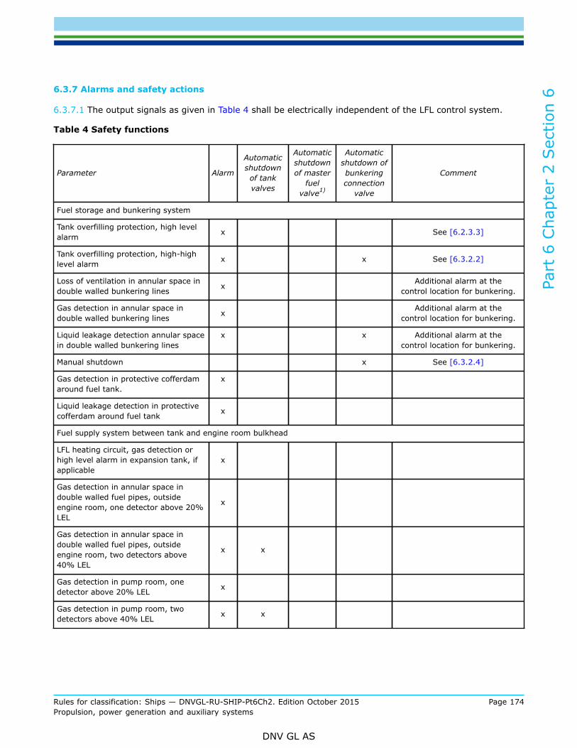
Part
6 C
hapt
er 2
Sec
tion
6
Rules for classification: Ships — DNVGL-RU-SHIP-Pt6Ch2. Edition October 2015 Page 174Propulsion, power generation and auxiliary systems
DNV GL AS
6.3.7 Alarms and safety actions
6.3.7.1 The output signals as given in Table 4 shall be electrically independent of the LFL control system.
Table 4 Safety functions
Parameter Alarm
Automaticshutdownof tankvalves
Automaticshutdownof master
fuelvalve1)
Automaticshutdown ofbunkeringconnection
valve
Comment
Fuel storage and bunkering system
Tank overfilling protection, high levelalarm x See [6.2.3.3]
Tank overfilling protection, high-highlevel alarm x x See [6.3.2.2]
Loss of ventilation in annular space indouble walled bunkering lines x Additional alarm at the
control location for bunkering.
Gas detection in annular space indouble walled bunkering lines x Additional alarm at the
control location for bunkering.
Liquid leakage detection annular spacein double walled bunkering lines
x x Additional alarm at thecontrol location for bunkering.
Manual shutdown x See [6.3.2.4]
Gas detection in protective cofferdamaround fuel tank.
x
Liquid leakage detection in protectivecofferdam around fuel tank x
Fuel supply system between tank and engine room bulkhead
LFL heating circuit, gas detection orhigh level alarm in expansion tank, ifapplicable
x
Gas detection in annular space indouble walled fuel pipes, outsideengine room, one detector above 20%LEL
x
Gas detection in annular space indouble walled fuel pipes, outsideengine room, two detectors above40% LEL
x x
Gas detection in pump room, onedetector above 20% LEL x
Gas detection in pump room, twodetectors above 40% LEL x x

Part
6 C
hapt
er 2
Sec
tion
6
Rules for classification: Ships — DNVGL-RU-SHIP-Pt6Ch2. Edition October 2015 Page 175Propulsion, power generation and auxiliary systems
DNV GL AS
Parameter Alarm
Automaticshutdownof tankvalves
Automaticshutdownof master
fuelvalve1)
Automaticshutdown ofbunkeringconnection
valve
Comment
Loss of ventilation in annular spacein double walled fuel pipes, outsideengine room
x x* *See [6.3.5]
Loss of ventilation in pump room x
Liquid leakage detection in annularspace in double walled fuel pipes,outside engine room
x x
Liquid leakage detection in pump room x x
Engine room
Gas detection in annular space indouble walled fuel pipes, inside engineroom, one detector above 30% LEL
x
Gas detection in annular space indouble walled fuel pipes, inside engineroom, two detectors above 40% LEL
x x
Liquid leakage detection in annularspace in double walled fuel pipes,inside engine room
x x
Loss of ventilation in annular space indouble walled fuel pipes, inside engineroom x x
This parameter shall only leadto LFL supply shutdown fordual fuel engines. However, see[6.3.5].
General
Manual shutdown x See [6.3.2.4].
1) Automatic or remote closing of master valve shall also stop LFL supply pumps
6.4 Engine monitoring6.4.1 General
6.4.1.1 In addition to the requirements given in Pt.4 Ch.3 Sec.1 [5], control and monitoring as given in Table5 is required for LFL engines.

Part
6 C
hapt
er 2
Sec
tion
6
Rules for classification: Ships — DNVGL-RU-SHIP-Pt6Ch2. Edition October 2015 Page 176Propulsion, power generation and auxiliary systems
DNV GL AS
Table 5 Monitoring of dual fuel diesel or LFL-only engines
System Item
Gr.1Indicationalarm loadreduction
Gr.2Automatic start
of standbypump withalarm 1)
Gr.3Shutdownwith alarm
Comments
1.0 Ignition system Ignition failure eachcylinder 2) A Automatic stop of fuel
supply 3)
2.0 Lubricating oilsystem
Cylinder lubricationflow 4) LA
Fuel injection valvecooling mediumpressure
HA ASAutomatic start of standbypump is not required ifmain pump is engine driven3.0 Fuel injection
valve cooling system Fuel injection valvecooling mediumtemperature
LA
4.0 LFL injection valvesealing oil system
LFL injection valvesealing oil pressure LA For high-pressure injection
only
5.0 Combustion Knocking A Only relevant for Ottoprocess
6.0 LFL supply Low pressure LA AS
Gr 1 = Common sensor for indication, alarm, load reductionGr 2 = Sensor for automatic start of standby pumpGr 3 = Sensor for shutdown.LA = Alarm for low valueHA = Alarm for high valueA = Alarm activatedSH = shutdown
1) Only for propulsion engines2) Exhaust temperature deviation may be accepted as means of detecting ignition failure, individually on each cylinder3) Fuel shutdown to the specific cylinder or the engine can be accepted4) At least one measuring point for each lubricator unit.
7 Engines and pumps
7.1 Pumps7.1.1 General
7.1.1.1 The fuel pumps shall be fitted with accessories and instrumentation necessary for efficient andreliable function.
7.1.1.2 The fuel supply pumps shall be arranged for manual remote emergency stop from the followinglocations:
— navigation bridge

Part
6 C
hapt
er 2
Sec
tion
6
Rules for classification: Ships — DNVGL-RU-SHIP-Pt6Ch2. Edition October 2015 Page 177Propulsion, power generation and auxiliary systems
DNV GL AS
— engine control room.
7.1.1.3 Hydraulically powered pumps that are submerged in fuel tanks (e.g. deep well pumps) shall bearranged with double barriers preventing the hydraulic system serving the pumps from being directlyexposed to the fuel. The double barrier shall be arranged for detection and drainage of possible fuel leakages.
7.2 Engines7.2.1 General
7.2.1.1 These paragraphs apply to both LFL fuel only engines and dual-fuel engines running in LFL fuel mode.
7.2.1.2 Measures shall be taken to ensure effective sealing of injection or admission equipment that couldpotentially leak fuel into the engine room.
7.2.1.3 Measures shall be taken to ensure that LFL fuel injection pumps and injection devices are efficientlylubricated.
7.2.1.4 The starting sequence shall be such that LFL fuel is not injected or admitted to the cylinders untilignition is activated and the engine has reached a minimum rotational speed.
7.2.2 Functional requirements for dual fuel engines
7.2.2.1 LFL dual fuel engines shall be arranged for start, normal stop and low power operation in fuel oilmode. In case of shut-off of the LFL fuel supply, the engine shall automatically transfer to operation on oilfuel only.
7.2.2.2 Changeover to and from LFL fuel operation is only to be possible at a power level where it canbe done with acceptable reliability as demonstrated through testing. On completion of preparations forchangeover to LFL operation including checks of all essential conditions for changeover, the changeoverprocess itself shall be automatic.
7.2.2.3 On normal shutdown as well as emergency shutdown, LFL fuel supply shall be shut off not later thansimultaneously switching to oil fuel mode.
7.2.2.4 Ignition of the LFL-air mixture in the cylinders shall be initiated by sufficient energy It shall not bepossible to shut off the ignition source without first or simultaneously closing the LFL fuel supply to eachcylinder or to the complete engine.
7.2.3 Functional requirements LFL-only engines
7.2.3.1 One single failure in the LFL fuel supply system shall not lead to total loss of fuel supply.Guidance note:May be waived in case of multi-engine installation.
---e-n-d---of---g-u-i-d-a-n-c-e---n-o-t-e---
7.2.3.2 The starting sequence shall be such that LFL fuel is not injected or admitted to the cylinders until ignition isactivated and the engine has reached a minimum rotational speed.
7.2.3.3 If ignition has not been detected by the engine monitoring system within the expected time after activationof fuel admission or injection valve, the LFL fuel supply shall be automatically shut off and the startingsequence terminated.

Part
6 C
hapt
er 2
Sec
tion
6
Rules for classification: Ships — DNVGL-RU-SHIP-Pt6Ch2. Edition October 2015 Page 178Propulsion, power generation and auxiliary systems
DNV GL AS
7.2.3.4 Measures for detected knocking shall be fitted.
8 Manufacture, workmanship and testing
8.1 General8.1.1 General
8.1.1.1 Fabrication and testing of the fuel system shall be in compliance with Pt.2 Ch.4, unless more strictrequirements are given in this section.
8.2 Fuel tanks8.2.1 Manufacture and testing
8.2.1.1 Testing of welds and non-destructive testing shall be carried out as specified for cargo tanks inchemical tankers in Pt.5 Ch.6 Sec.5. Strength and tightness testing shall be carried out as specified in Pt. 2Ch. 3 Sec. 8 as applicable for cargo tanks in chemical tankers.
8.3 Piping system8.3.1 Manufacture and testing
8.3.1.1 The LFL piping (inner pipe) shall be joined by butt welding with a minimum of flange connections.
8.3.1.2 Flanges in secondary enclosures for fuel piping shall be of the welding neck, slip-on or socket weldingtype.
8.3.1.3 In addition to normal controls before and during the welding, and to the visual inspection of thefinished welds, as necessary for proving that the welding has been carried out correctly, the LFL pipe shall besubject to 100% radiographic or ultrasonic inspection of butt-welded joints.
8.3.1.4 After assembly on board, the fuel piping system shall be subjected to a leak test using air, or othersuitable medium to a pressure depending on the leak detection method applied. Secondary enclosures forlow pressure gas piping shall be tightness tested.
8.4 Onboard testing8.4.1 General
8.4.1.1 Control, monitoring and safety systems required by these rules, shall be tested onboard inaccordance with Pt.4 Ch.9 Sec.1 [4.5].
8.4.1.2 The functionality of the cause and effect diagram required by Table 2 shall be tested onboard.
Part
6 C
hapt
er 2
Sec
tion
6
Rules for classification: Ships — DNVGL-RU-SHIP-Pt6Ch2. Edition October 2015 Page 179Propulsion, power generation and auxiliary systems
DNV GL AS
9 Operation Manual
9.1 General9.1.1 General
9.1.1.1 An operation manual describing all essential procedures for handling of LFL fuel shall be prepared.The manual is subject to approval and shall be kept on board.
9.1.1.2 The operation manual is in general to include the following items:
1) Ship particulars2) Fuel system particulars:
— fuel properties— fuel tank capacities— fuel handling system— inert gas N2— fuel tank venting— fuel pump room safety if applicable— fuel tank instrumentation— fire safety— gas detection— liquid leakage detection— emergency water filling of cofferdams.
3) Operations:
— assumptions— bunkering— fuel transfer between tanks— normal operation of the fuel system— cleaning, purging and gas freeing— tank entry procedures— cofferdam safety— gas detection— fuel pump room safety— emergency operations related to LFL fuel hazards— medical treatment procedures for exposure to the LFL fuel.
4) Reference documents:
— general arrangement— LFL fuel system— pressure/vacuum valves flow curves— nitrogen system— fuel tank venting— hazardous zones— fire extinguishing— procedure and arrangement manual (if applicable)— bilge system for cofferdam and pump room.
9.1.1.3 The following instructions shall be included in the operation manual as applicable:

Part
6 C
hapt
er 2
Sec
tion
6
Rules for classification: Ships — DNVGL-RU-SHIP-Pt6Ch2. Edition October 2015 Page 180Propulsion, power generation and auxiliary systems
DNV GL AS
— the fuel tanks shall be filled with inert gas and the O2-content in the tanks shall not exceed 5% by volume— the control and safety systems shall be function tested.
10 Personnel protection
10.1 General10.1.1 General
10.1.1.1 Personnel protection shall be in compliance with Pt.5 Ch.6 Sec.17. It is sufficient with two completesets of safety equipment instead of three as required in Pt.5 Ch.6 Sec.17 [2.1.1].
11 Ship type considerations
11.1 Chemical tankers11.1.1 General
11.1.1.1 This section covers special considerations for LFL cargo used as fuel on chemical tankers certified forthe carriage of the relevant LFL fuel, based on the following:
— the risk of a fire/explosion in the cargo area spreading to the fuel supply system,— the risk of inadvertent transfer of incompatible or contaminating cargo to the fuel system— the risk of fire/explosion associated with increased frequency of use of piping systems for transfer of LFL
fuel/cargo from service tank to engine room and transfer from a cargo tank to service tank (when a cargotank is dedicated as a LFL fuel storage tank).
11.1.2 Arrangement
11.1.2.1 A dedicated LFL fuel service tank shall be provided. The piping system serving this tank shall beseparated from cargo handling piping systems, except for the fuel transfer pipes from tanks for fuel storage.
11.1.2.2 The LFL fuel service tank(s) and fuel pump room shall be located in cargo area.
11.1.3 Fire safety
11.1.3.1 Measures shall be implemented to reduce the consequences of fire and explosions in cargo tanksand in the cargo area for the dedicated LFL fuel service tanks and LFL fuel supply systems.
11.1.3.2 Inerting of cargo tanks during cargo tank cleaning operations and inert gas purging prior to gas-freeing would be considered an acceptable measure to reduce the consequence of in-tank explosion. Suchinerting should be performed for all cargo tanks and LFL fuel tanks regardless of size of ship.
11.1.3.3 The LFL fuel tanks shall be covered by the cargo deck fire/foam extinguishing system. Additionalfoam monitors/foam sprinklers shall be fitted, if necessary.
11.1.3.4 The exterior boundaries of the LFL fuel service tank(s) and the fuel pump room shall be protectedby a water spray system for cooling and fire prevention. The spraying capacity shall not be less than 10 l/min/m2 for horizontal projected surfaces and 4 l/min/m2 for vertical surfaces.
11.1.3.5 The system shall be served by a separate water spray pump with capacity sufficient to deliver therequired amount of water as specified in Sec.4.

Part
6 C
hapt
er 2
Sec
tion
6
Rules for classification: Ships — DNVGL-RU-SHIP-Pt6Ch2. Edition October 2015 Page 181Propulsion, power generation and auxiliary systems
DNV GL AS
11.1.3.6 A connection to the ships fire main through a stop valve shall be provided.
11.1.4 Segregation of cargo- and fuel system
11.1.4.1 Measures shall be provided to prevent inadvertent transfer of incompatible or contaminating cargoto the fuel system, after the fuel storage tanks have been loaded.
11.1.4.2 If cargo tanks located within the cargo area are used as LFL fuel storage tanks, these cargo tanksshall be dedicated as LFL fuel tanks when the ship is operating on LFL fuel.
11.1.4.3 Any cargo liquid line for dedicated LFL fuel storage tanks shall be separated from liquid cargo pipingserving other cargo tanks, including common liquid cargo piping.
11.1.4.4 Cross-connections to cargo liquid piping serving common systems or other tanks may be acceptedprovided the connections are arranged with spool pieces. The arrangement of spool pieces shall be such thateven if a spool piece is unintentionally left in place, inadvertent transfer of incompatible or contaminatingcargo from or to the dedicated LFL fuel storage tank is not possible.
Guidance note:An arrangement with swing bends would normally be the preferred spool piece arrangement to prevent unintentional transfer to orfrom LFL fuel storage tanks.
---e-n-d---of---g-u-i-d-a-n-c-e---n-o-t-e---
11.1.4.5 The cargo tank venting system for the dedicated LFL fuel tanks shall be separated from ventingsystems from other cargo tanks when operating on LFL fuel.
11.1.4.6 Other cargo handling systems serving other cargo tanks such as tank washing, inert gas and vapourreturn shall be separated when used as LFL fuel storage tanks. Inert gas systems may be accepted connectedto a common system when used as LFL fuel storage tanks, provided the system is under continuouspressure.
11.1.4.7 LFL fuel tank location shall take into account compatibility with other cargoes. When carrying LFLfuel in the storage tanks, these tanks cannot be located adjacent to cargo tanks intended for cargoes that arenot compatible with the LFL fuel.
11.1.4.8 For tankers arranged for operation on LFL fuel only, the following additional requirements apply:
— the fuel storage tanks and piping system shall be independent of cargo handling systems serving cargotanks.
— if the LFL service tank is located within the cargo area, in case of shutdown of LFL fuel supply, the shipshall be provided with sufficient alternative power supply for operating the safety functions onboard (e.g.fire and foam extinguishing, fire and gas detection and alarm, ballast, bilge drainage, LFL fuel safetysystems).
11.2 Passenger vessels11.2.1 General
11.2.1.1 Areas classified as hazardous zone as given in, [5.2.2] shall be inaccessible for passengers at alltimes.
11.2.1.2 The aft- and forepeak in passenger vessels cannot be used as cofferdam space for a LFL fuel tank.

Part
6 C
hapt
er 2
Sec
tion
6
Rules for classification: Ships — DNVGL-RU-SHIP-Pt6Ch2. Edition October 2015 Page 182Propulsion, power generation and auxiliary systems
DNV GL AS
11.3 Offshore supply vesselsGeneral
11.3.1 LFL fuel tanks on deck are not accepted on offshore supply vessels.
11.3.1.1 The aft- and forepeak in offshore supply vessels cannot be used as cofferdam space for a LFL fueltank.

Part
6 C
hapt
er 2
Sec
tion
7
Rules for classification: Ships — DNVGL-RU-SHIP-Pt6Ch2. Edition October 2015 Page 183Propulsion, power generation and auxiliary systems
DNV GL AS
SECTION 7 REDUNDANT PROPULSION - RP
1 General
1.1 IntroductionThe additional class notation RP introduces rules to ensure that the propulsion and steering systems willremain in operation, or be restored to a certain degree, after a single failure. The choice of notationsdetermines the level of system redundancy. The suffix "x" indicates the remaining power capacity afterfailure and for qualifier "+" the required capacity shall be maintained without disruption.
1.2 ScopeThe scope for additional class notation RP adds an increased level of safety as the availability of thepropulsion and steering functions are increased. The design shall ensure that the propulsion and steeringsystems will remain in operation, or be restored to a certain degree, after a single failure. The propulsionand steering systems arrangement shall be evaluated in an FMEA. The additional class notation RP does notinclude requirements or recommendations concerning the vessel's operation or other characteristics. Therequirements of the rules in this section are supplementary to the main class rules.
1.3 ApplicationVessels build and tested for compliance with the requirements of the rules of this section may be assigneda variant of the additional class notation RP, as given in Table 1 - Examples of arrangements for classnotations. For example: RP(1, x) can be assigned to systems arrangement where main and alternativepropulsion are provided by a common propulsion system with redundant prime movers, RP(2, x) canbe assigned to system arrangement of two propulsion systems operating in parallel and RP(3, x) can beassigned to system arrangement of two propulsion systems separated by A-60 bulkheads and operating inparallel. The suffix "x" indicates that at least x% of the propulsion power can be restored and maintainedafter single failure. An additional qualifier "+" can be included in RP(2, x) and RP(3, x) notations when thepropulsion and steering systems are of a redundant design such that the required propulsion and steeringcapacity are maintained without disruption upon single failure; this will require extended analysis andverification of the design.
Table 1 RP class notations
Notation Description
RP(1, x))
Main and alternative propulsion is provided by a common propulsion system (one propeller, oneshaft and one rudder/steering gear) with redundant prime movers or by separate propulsors (twoor more propellers), such that at least x% of the propulsion power can be restored and maintainedafter single failure e.g.:
— two prime movers with clutch, where one of the prime movers may be of power take in type,connected to a common gear, one shaft line and one rudder.
— one prime mover, one shaft line and one rudder providing the main propulsion system andone separate alternative propulsion system, e.g. azimuth or pod thruster capable of providingmanoeuvrability.
See Figure 1
Guidance note:A retractable azimuth thruster can be accepted as alternative propulsion.
---e-n-d---of---g-u-i-d-a-n-c-e---n-o-t-e---

Part
6 C
hapt
er 2
Sec
tion
7
Rules for classification: Ships — DNVGL-RU-SHIP-Pt6Ch2. Edition October 2015 Page 184Propulsion, power generation and auxiliary systems
DNV GL AS
Notation Description
RP(2, x)
The vessel propulsion and steering system is of a redundant design with two (or more) propellersin parallel operation such that the availability of at least x% propulsion power and associatedsteering system can be restored and maintained after single component failure.
See Figure 2
RP(3, x)
The vessel propulsion and steering system is of a redundant design with two (or more) propellersin parallel operation and separated by watertight A-60 bulkheads such that the availability of atleast x% propulsion power and associated steering system can be restored and maintained aftersingle component failure and upon incidents of fire or flooding.
See Figure 3
Figure 1 Examples RP(1, x)
Figure 2 Examples RP(2, x)
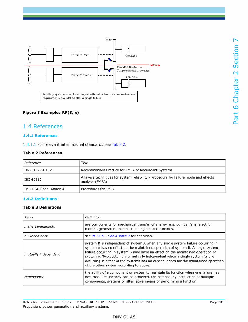
Part
6 C
hapt
er 2
Sec
tion
7
Rules for classification: Ships — DNVGL-RU-SHIP-Pt6Ch2. Edition October 2015 Page 185Propulsion, power generation and auxiliary systems
DNV GL AS
Figure 3 Examples RP(3, x)
1.4 References1.4.1 References
1.4.1.1 For relevant international standards see Table 2.
Table 2 References
Reference Title
DNVGL-RP-D102 Recommended Practice for FMEA of Redundant Systems
IEC 60812 Analysis techniques for system reliability - Procedure for failure mode and effectsanalysis (FMEA)
IMO HSC Code, Annex 4 Procedures for FMEA
1.4.2 Definitions
Table 3 Definitions
Term Definition
active components are components for mechanical transfer of energy, e.g. pumps, fans, electricmotors, generators, combustion engines and turbines.
bulkhead deck see Pt.3 Ch.1 Sec.4 Table 7 for definition.
mutually independent
system B is independent of system A when any single system failure occurring insystem A has no effect on the maintained operation of system B. A single systemfailure occurring in system B may have an effect on the maintained operation ofsystem A. Two systems are mutually independent when a single system failureoccurring in either of the systems has no consequences for the maintained operationof the other system according to above.
redundancythe ability of a component or system to maintain its function when one failure hasoccurred. Redundancy can be achieved, for instance, by installation of multiplecomponents, systems or alternative means of performing a function

Part
6 C
hapt
er 2
Sec
tion
7
Rules for classification: Ships — DNVGL-RU-SHIP-Pt6Ch2. Edition October 2015 Page 186Propulsion, power generation and auxiliary systems
DNV GL AS
Term Definition
redundancy group
all components and systems that is subject to a single failure as specified in [2.1]for the specific notations.
Guidance note:The redundancy groups will emerge as a consequence of the worst case single failurewithin each group. The Rules does not give requirements to the number of (beyond 2) orratio between the defined groups. The groups are to be identified in the FMEA, verifiedby testing and incorporated in the consequence analysis.
---e-n-d---of---g-u-i-d-a-n-c-e---n-o-t-e---
remaining propulsion power is the vessels available propulsion power after the occurrence of a failure
worst case failure
failure modes which cause the largest reduction of the propulsion and steeringcapacity. This means loss of the most significant redundancy group, given theprevailing operation. Failure modes related to the different class notations are givenin [2].
1.4.3 Abbreviations
1.4.3.1 Relevant abbreviations are given in Table 4.
Table 4 Abbreviations
Abbreviation In full
FMEA Failure Mode and Effect Analysis
UPS Uninterruptible Power Supply
MCR Maximum Continuous rating
1.5 Procedural Requirements1.5.1 Document requirements
1.5.1.1 The propulsion, power generation and steering systems, with their auxiliaries and remote controlshall be documented according to main class. In addition, documentation shall be submitted as required byTable 5

Part
6 C
hapt
er 2
Sec
tion
7
Rules for classification: Ships — DNVGL-RU-SHIP-Pt6Ch2. Edition October 2015 Page 187Propulsion, power generation and auxiliary systems
DNV GL AS
Table 5 Documentation required
System Documentation type Additional description Info Notation
Z050 – Design philosophy
The document shall identify the redundancydesign intent and describe the propulsionand steering arrangement and if applicablethe alternative propulsion arrangement. Inorder to determine the suffix (x) the mainpropulsion capacity MCR must be specifiedfor each propeller, and if applicable for thealternative propulsion. For electric propulsionsystem the power available for propulsionor alternative propulsion after worst casefailure must be specified. The document shallalso specify the intended technical systemconfiguration(s) which shall be verified againstthe requirements of the relevant notation.
AP All
Z071 - Failure mode andeffect analysis (FMEA) *)
Including conclusive evidence that uponany single failure in required duplicatedcomponents or systems, and for RP(3, x) alsoincident of fire or flooding, x propulsion powerand steering capability can be restored andmaintained at least up to the degree expressedby the suffix x.
AP All
Z253 - Test procedure forquay and sea trial *)
An FMEA test procedure for failure testing atthe sea trial to verify the conclusions in theFMEA. This shall be based upon the failuremodes identified, and the vessel system setupas specified in the FMEA, see [1.3.1.11].
AP All
I060 Principal cablerouting sketch
All relevant cables for all systems required torestore and maintain propulsion and steering. AP RP(3, x)
Z030 - Arrangement planFire and flooding separation. Also indicationof the different fire zones allocated to theinstallation of the redundant equipment.
AP RP(3, x)
Propulsionand steeringarrangement
Z265 - Calculation reportDocumentation to demonstrate compliancewith capacity requirements given in [2.1.1.3]and [2.1.1.4] or [3.1.1.5] and [3.1.1.10].
FI All
*) for a more extensive description on the requirements, see below.
1.5.1.2 A Failure Mode and Effect Analysis, FMEA, for the complete propulsion and steering systems, withtheir auxiliaries, shall be submitted for approval. The FMEA shall show that redundancy requirements arefulfilled where relevant.
1.5.1.3 The purpose of the FMEA is to identify and describe the different failure modes of the equipmentwhen referred to its functional task. Special attention shall be paid to the analysis of systems that may entera number of failure modes and thus induce a number of different effects on the propulsion and steeringperformance. The FMEA shall include at least the information specified in [1.3.1.4] to [1.3.1.10].
1.5.1.4 The FMEA shall give general vessel information and clearly describe the design intent and theintended overall redundancy and acceptance criteria. The technical system configuration(s) to be verified
Part
6 C
hapt
er 2
Sec
tion
7
Rules for classification: Ships — DNVGL-RU-SHIP-Pt6Ch2. Edition October 2015 Page 188Propulsion, power generation and auxiliary systems
DNV GL AS
shall be described, and prerequisites for achieving the required failure tolerance and redundancy shall bespecified.
Guidance note:Technical system configuration(s) may be setting of any valve cross-over, power feed change-over arrangement condition etc..
---e-n-d---of---g-u-i-d-a-n-c-e---n-o-t-e---
1.5.1.5 A breakdown of the systems, into functional blocks shall be made. The functions of each block shallbe described. The breakdown shall be performed to such a level of detail that the design intent can bedocumented.
1.5.1.6 A description of each functional block shall be made and all associated failure modes with their failurecauses shall be identified for normal operational modes.
1.5.1.7 A description of the effects of each failure mode on the functional block, and on the propulsion andsteering function shall be made.
1.5.1.8 A description of the arrangement and installation of redundant component groups in fire and floodingprotected compartments shall be provided for RP(3, x). This also includes cables and communication lines,and associated equipment.
1.5.1.9 Compliance statements referring to the design intent and acceptance criterion shall be made.
1.5.1.10 The FMEA shall be a self-contained document including all necessary descriptions, supportingdocuments and drawings in order to document the conclusions.
Guidance note 1:Description of FMEA systematic may be found in the documents RP-D102 FMEA of Redundant Systems, IEC 60812 and IMO HSCCode, Annex 4.
---e-n-d---of---g-u-i-d-a-n-c-e---n-o-t-e---
Guidance note 2:Separate FMEAs covering control systems (as supplied by manufacturer) should be incorporated in the overall system FMEA (assupplied by the yard).
---e-n-d---of---g-u-i-d-a-n-c-e---n-o-t-e---
1.5.1.11 A test program to support the conclusions shall be included or referred. This test program shall alsobe submitted for approval and shall be used for the final sea trial of the complete redundant propulsion andsteering systems. The test program shall be based upon the failure modes identified in the FMEA in order toverify the conclusions. References shall be made between the FMEA and the FMEA test program.
1.5.1.12 FMEA(s) and FMEA test program(s) shall be kept on board and at all times and be kept updated tocover alterations to the propulsion and steering systems.
1.5.1.13 For vessels with qualifier +, the FMEA shall be extended to cover additional failure modes applicablefor the technical system configuration(s) of the power generation and switchboard specified in the systemdesign philosophy, see [3.2.4].
1.5.2 Certification required
1.5.2.1 Equipment shall be certified according to main class requirements.

Part
6 C
hapt
er 2
Sec
tion
7
Rules for classification: Ships — DNVGL-RU-SHIP-Pt6Ch2. Edition October 2015 Page 189Propulsion, power generation and auxiliary systems
DNV GL AS
1.5.3 Survey and test requirements
1.5.3.1 For initial issue of class notation upon completion, the propulsion and steering systems, with theirauxiliaries, shall be subjected to final tests during sea trials, in compliance with the requirements for mainclass.
1.5.3.2 A selection of tests within each system analysed in the FMEA shall be carried out, including simulationof fire and flooding incidents when required. Specific conclusions of the FMEA for the different systems shallbe verified by tests when redundancy or independence is required. The test program required in [1.3.1.11]shall be used for this testing.
Guidance note:For RP(3, x) this implies that simultaneous loss of all systems in relevant fire zones or flooded compartments should be tested.
---e-n-d---of---g-u-i-d-a-n-c-e---n-o-t-e---
1.5.3.3 The test procedure for redundancy shall be based on the simulation of failures and shall be performedunder as realistic conditions as practicable.
Guidance note:It is understood that not all failure modes in all systems are possible to simulate. For such failure modes the acceptance of thesystem will be based on the theoretical FMEA, and hence the documentation analysis of these failure modes should be emphasizedin the FMEA.
---e-n-d---of---g-u-i-d-a-n-c-e---n-o-t-e---
1.5.3.4 It is not required that the built-in endurance as required by [2.1.1.3] and [2.1.1.4] and by [3.1.1.5]and [3.1.1.10] be demonstrated. However, time-critical resources shall be substantiated by adequate tests ofrate of consumption and depletion.
1.5.3.5 The capability of the of the remaining propulsion system after the worst case single failure scenariosshall be tested at sea to demonstrate that the propulsion power and steering capabilities as indicated bythe notation x can be achieved with satisfactory thermal stability and performance of the machinery plantincluding necessary auxiliaries.
1.5.3.6 For RP(2, x) and RP(3, x) steering gear function and capacity test as listed by Pt.4 Ch.10 SteeringGear shall be performed for the remaining system after a worst case failure (This shall be verified afterfailure of any one redundancy groups).
1.5.3.7 For RP(1, x) notation, the time necessary to activate the alternative propulsion system after failureof the main propulsion system shall be demonstrated.
1.5.3.8 For RP(1, x) notation, a speed trial is to be performed with the alternative propulsion systemconsisting of at least two legs in opposite direction, to compensate influence of wind and current. Forseparate alternative propulsion units, also the steering capability of the unit shall be demonstrated anddocumented.
1.5.3.9 When deemed necessary by the attending surveyor, tests additional to those specified by the testprogram may be required.

Part
6 C
hapt
er 2
Sec
tion
7
Rules for classification: Ships — DNVGL-RU-SHIP-Pt6Ch2. Edition October 2015 Page 190Propulsion, power generation and auxiliary systems
DNV GL AS
2 Technical requirements for RP(1, x)
2.1 General2.1.1 Basic requirements
2.1.1.1 The design shall ensure the ability of the main or alternative propulsion system to be brought to andremain in operation after the occurrence of any single failure, as specified in [2.1.2].
2.1.1.2 The alternative propulsion shall, when brought into operation, be designed for continuous operation.Guidance note:Generally no restrictions should be put on the starting intervals of electrical machines. If arranged, the arrangement is subject toapproval in each case.
---e-n-d---of---g-u-i-d-a-n-c-e---n-o-t-e---
2.1.1.3 The alternative propulsion system power capacity shall be such that it will enable the vessel tomaintain a speed of not less than 7 knots.
2.1.1.4 The vessel shall be able to proceed with the propulsion power required in [2.1.1.3] for a period of atleast 72 hours.For vessels built for a specific service where the duration of a sea voyage is less than 72 hours, the built-in endurance of the alternative propulsion system may be limited to the duration of the maximum crossingtime, but not less than 12 hours.
Guidance note:In case a vessel is built to proceed with the alternative propulsion system for a period of less than 72 hours, this limitation will bestated in the appendix to the classification certificate.
---e-n-d---of---g-u-i-d-a-n-c-e---n-o-t-e---
2.1.1.5 It shall be possible to activate the alternative propulsion system within maximum 30 minutes afterfailure of the main propulsion system, except for failures in common active and passive components wherecommon components have been specially accepted.
Guidance note:Activation of the alternative propulsion may involve manual mechanical work provided that procedures and equipment necessaryfor activation is kept on-board the vessel, and that activation of the alternative propulsion (with the required capacity) within 30minutes can be demonstrated at sea trials.
---e-n-d---of---g-u-i-d-a-n-c-e---n-o-t-e---
2.1.2 Failure modes
2.1.2.1 The defined failure modes include failure of any active component or system, except for failures incommon active components specially accepted as common. This includes normally propeller, shaft and gearfor the arrangement of one propeller shaft train with two driving units acting via the common gear box.
2.2 System configuration2.2.1 General
2.2.1.1 The basic requirements for providing the alternative propulsion power are as described in [1.1.3.1].

Part
6 C
hapt
er 2
Sec
tion
7
Rules for classification: Ships — DNVGL-RU-SHIP-Pt6Ch2. Edition October 2015 Page 191Propulsion, power generation and auxiliary systems
DNV GL AS
2.2.2 Electrical power distribution
2.2.2.1 The power distribution to both the main and alternative propulsion systems and their respectiveauxiliary systems shall be arranged so that at least one of the propulsion systems are capable of being putinto operation and operated after loss of any single switchboard section.
2.2.3 Electrical power plant control
2.2.3.1 The power plant control system shall be arranged so that a single failure shall not jeopardise bothmain and alternative propulsion.
2.3 Auxiliary systems2.3.1 General
2.3.1.1 Auxiliary systems for the main propulsion system shall be arranged as required by 1A1 main classrequirements. Separate active components shall be arranged for the alternative propulsion auxiliary systems.For additional requirements to specific auxiliary functions see [2.3.2] to [2.3.4].
2.3.2 Fuel oil
2.3.2.1 The transfer and fuel oil pre-treatment systems and tank arrangements shall be able to support thepower capacity required by [2.1.1.3] for the period specified in [2.1.1.4] after a single failure as specifiedin [2.1.2.1], unless fuel which do not require pre-treatment are arranged for the period. Fuel pre-treatmentshall be understood as all equipment for purification, filtering, heating, and measuring fuel oil.
2.3.3 Lubrication oil system
2.3.3.1 The main propulsion system and the alternative propulsion system shall have independent lubricationoil systems.
2.3.3.2 The lubrication oil storage and purification system shall be able to support the power capacityrequired by [2.1.1.3] for the period specified in [2.1.1.4] after a single failure as specified in [2.1.2.1].
2.3.4 Compressed air system
2.3.4.1 The starting air system shall comply with main class for the main propulsion, and with adequatefacilities to enable three starting attempts for the alternative propulsion.
2.4 Propulsion and steering control systems2.4.1 General
2.4.1.1 When a centralised control system is arranged, the control system arrangement shall comply with therequirements for redundancy and separation as given by these rules.
2.4.2 Propulsion control system
2.4.2.1 Independent local control for main and alternative propulsion system shall be arranged consistentwith the failure concept given in [2.1.1.1]. Each system shall include a separate control panel. Such meansshall be operable after any failure of the centralized control system installation on the navigating bridge.
2.4.2.2 Reliable means of communication, also operable during black-out, between the navigating bridge andthe emergency/local control stations shall be arranged for main and for alternative propulsion.
Part
6 C
hapt
er 2
Sec
tion
7
Rules for classification: Ships — DNVGL-RU-SHIP-Pt6Ch2. Edition October 2015 Page 192Propulsion, power generation and auxiliary systems
DNV GL AS
2.4.2.3 Remote control of both the main and the alternative propulsion systems shall be installed at thenavigating bridge. The navigating bridge main and alternative remote propulsion control systems shall beindependent of each other, so that any single failure will only affect one of them.
Guidance note:Mechanical levers are not required to be duplicated.
---e-n-d---of---g-u-i-d-a-n-c-e---n-o-t-e---
2.4.3 Control power sources
2.4.3.1 Power supply for main and alternative propulsion and steering systems shall be distributed consistentwith the redundancy requirement [2.1.1.1].
2.4.4 Steering control system
2.4.4.1 If alternative propulsion and steering is realized by a second driven unit e.g. independent steerablethruster or water jet:
a) Steering systems related to main and alternative propulsion shall be independent.b) For the steering system related to alternative propulsion, strength and capacity shall be as required for
main system, but at a vessel speed only corresponding to the maximum speed (minimum 7 knots) whenpropulsion power is provided by alternative unit only. The steering system for alternative propulsion doesnot need to include an auxiliary steering gear.
3 Technical requirements for RP(2, x) and RP(3, x)
3.1 System design3.1.1 Redundancy concept
3.1.1.1 The redundancy concept shall ensure the ability of the system to be restored and/or to remain inoperation in accordance with the objectives of the specific notation. This covers the following aspects:
— propulsion— steering— recovery time— endurance.
3.1.1.2 The propulsion system forming the required redundancy shall be intended to provide propulsionduring normal operation
3.1.1.3 PropulsionFor notation RP(2, x) the vessel's propulsion system shall be of a redundant design such that at least x% ofthe propulsion power can be restored after any single failure in the propulsion and auxiliary systems, beforethe vessel has lost steering speed. For definition of failure modes see [3.1.2].
Guidance note 1:The remaining propulsion power after loss of one propulsion line may in practice be less than x% due to hydro-dynamical propertiesof the vessel when operating at lower speed.
---e-n-d---of---g-u-i-d-a-n-c-e---n-o-t-e---
Guidance note 2:Vessels designed and built with a larger degree of separation than 2 will be subject to special evaluation.
---e-n-d---of---g-u-i-d-a-n-c-e---n-o-t-e---

Part
6 C
hapt
er 2
Sec
tion
7
Rules for classification: Ships — DNVGL-RU-SHIP-Pt6Ch2. Edition October 2015 Page 193Propulsion, power generation and auxiliary systems
DNV GL AS
3.1.1.4 For notation RP(3, x), the requirement to ensure at least x% of the propulsion power as described in[3.1.1.3], also includes single failure of one compartment caused by fire and flooding incidents. For definitionof failure modes see [3.1.2].
3.1.1.5 The remaining propulsion power capacity (as described in [3.1.1.3]) shall enable the ship to maintaina speed of not less than 6 knots while heading into BF 8 weather conditions with corresponding waveconditions. The requirement shall be documented by computation where relevant wave spectrum is utilised.
Guidance note:For vessels engaged in specialised operations, e.g. seismic, pipe layers, vessels engaged in confined waters etc, the propulsion powercapacity after a failure should be sufficient to keep the vessel and equipment in a safe condition after a failure. This should bedetermined together with the ship owner based on the vessel operations. Written acceptance of the propulsion capabilities shall beprovided from the owner.
---e-n-d---of---g-u-i-d-a-n-c-e---n-o-t-e---
3.1.1.6 SteeringThe steering arrangement shall consist of two independent steering systems, each in compliance with themain class rules.
Guidance note:In a typically installation of two steering gear systems two pumps are fed from the emergency switchboard and two pumps are fedfrom each side of the main switchboard. One single failure may then initially cause loss of three pumps which is accepted.
---e-n-d---of---g-u-i-d-a-n-c-e---n-o-t-e---
3.1.1.7 The vessel shall be fully manoeuvrable when operating one (1) propulsion and one (1) steeringsystem.
Guidance note:This implies that each steering system should comply with main class requirements for rudder (or equivalent means, e.g. thrusters)movement when only one propulsion and one steering system is in operation.
---e-n-d---of---g-u-i-d-a-n-c-e---n-o-t-e---
3.1.1.8 Qualifier +:The vessels propulsion system shall be of a redundant design such that at least x% of the propulsion powerand at least one associated steering system will be maintained without disruption upon any single failure.Redundancy shall be based on running machinery. Full stop of propulsion or steering systems and subsequentstart-up of available propulsion or steering is considered as a disruption, and not acceptable. In addition, anyspecific requirements as stated in these rules for qualifier +,shall be complied with.
Guidance note:The redundancy requirements will not be considered as complied with if based upon manual or automatic start or restart of generatorsor pumps, or if based upon automatic or manual reconfiguration of auxiliary systems e.g. by use of valves. Automatic activation ofequipment may be accepted as contributing to redundancy only if their reliability and simplicity of operation is satisfactory so thatthey can be brought into operation before propulsion power is degraded below x%. This principle is typically only accepted for transferof control between redundant controllers and for standby start of sea water cooling pumps for RP2 (x%).
---e-n-d---of---g-u-i-d-a-n-c-e---n-o-t-e---

Part
6 C
hapt
er 2
Sec
tion
7
Rules for classification: Ships — DNVGL-RU-SHIP-Pt6Ch2. Edition October 2015 Page 194Propulsion, power generation and auxiliary systems
DNV GL AS
3.1.1.9 Recovery time for notations without qualifier +:To ensure the required x% propulsion power, restoration of dedicated systems is allowed as long as therestoration process is completed before the vessel has lost steering speed
Guidance note:The objective of the above stated link between recovery of the propulsion power and steering capability is to allow more time whenthe vessel is at transit speed in open waters than when the vessel is proceeding at reduced speed in congested waters, in or is in amanoeuvring situation. This implies that systems which are not continually available should be prepared for service before enteringcritical situations where the recovery time otherwise would be too long in view of external hazards.
---e-n-d---of---g-u-i-d-a-n-c-e---n-o-t-e---
3.1.1.10 EnduranceAfter any single failure the vessel shall be able to proceed with the required remaining propulsion power for aperiod of at least 72 hours.
3.1.1.11 For vessels built for a specific service where the duration of a sea voyage is less than 72 hours,the built-in endurance at the required remaining propulsion power may be limited to the duration of themaximum crossing time but not less than 12 hours.
Guidance note:The propulsion power period after failure should be determined together with the ship owner based on the vessel operation area.Written acceptance of the propulsion capabilities shall be provided from the owner.
---e-n-d---of---g-u-i-d-a-n-c-e---n-o-t-e---
3.1.2 Failure modes
3.1.2.1 For the RP(2, x) notation, the defined failure modes include component breakdown andmalfunctions, but exclude the effects of fire and flooding. Thus, it is acceptable that redundant componentsare installed in a common area or compartment.
3.1.2.2 In addition to active components, the component breakdown as stated above shall include the failureof the following components:
— coolers and heat exchangers— filters— motorised valves— boilers— transformers— switchgear— cables— systematic failures or faults that can be hidden until a new fault appears.
See [3.3] for more specific requirement.
3.1.2.3 For the RP(3, x) notation, the failure modes include all those defined for RP(2, x), in addition toany failure in the propulsion and steering systems that will result from incidents of fire and flooding. Hence,redundant components and systems shall be located in different fire sub-divisions. The sub-divisions areto be watertight below the bulkhead deck. Reference is also made to the separation requirements given in[3.5].
Guidance note:Loss of stability (e.g. as a result of flooded compartments) is not a relevant failure mode.
---e-n-d---of---g-u-i-d-a-n-c-e---n-o-t-e---

Part
6 C
hapt
er 2
Sec
tion
7
Rules for classification: Ships — DNVGL-RU-SHIP-Pt6Ch2. Edition October 2015 Page 195Propulsion, power generation and auxiliary systems
DNV GL AS
3.2 System configuration3.2.1 General
3.2.1.1 The basic requirement of maintaining at least x% of propulsion MCR power shall be realised byinstallation of at least two mutually independent propulsion systems.
Guidance note:The minimum of x% propulsion power is to be understood as the nominal power consumption of one propeller when operating withall propulsion systems together. I.e. the deviations in thrust output caused by changes in vessel speed and propeller r.p.m. at lossof one propulsion system need not to be considered.
---e-n-d---of---g-u-i-d-a-n-c-e---n-o-t-e---
3.2.1.2 Typical configuration will consist of two propulsion lines, alternatively two azimuth thrusters. Thenormal operation mode is to run both systems in parallel, and upon a failure one system will continue inoperation. Two independent engine systems geared onto one propeller are not considered equivalent.
3.2.1.3 The redundancy in steering function shall be realised by the installation of two (or more) mutuallyindependent steering systems, e.g. two rudders or two azimuth thrusters. Each steering system, withsteering controls and actuators, shall comply with the main class rules. This implies that each steeringsystem shall be provided with a main and an auxiliary steering gear.
Guidance note:Vessels designed and built with a larger degree of separation than 2 will be subject to special evaluation.
---e-n-d---of---g-u-i-d-a-n-c-e---n-o-t-e---
3.2.1.4 After failure of one propulsion system, the steering capability, as required for main steering gear,shall be available at the maximum achievable speed.
3.2.2 Electrical power generation
3.2.2.1 The electrical power required for propulsion, steering and auxiliary systems shall be generated by apower plant complying with main class requirements of Pt.4 and the redundancy, capacity, separation andsingle failure integrity as specified for the given notation.
3.2.2.2 The vessel shall be capable of operating with the emergency switchboard out of operation.
3.2.3 Electrical power distribution
3.2.3.1 When power for propulsion, steering and their auxiliaries is supplied from one switchboard, the bus-bars of the switchboard shall be arranged for automatic separation into at least 2 sections, with the circuitsfor propulsion and steering units and auxiliaries distributed between the sections. Automatic separation shalltake place when short circuit currents are detected on the main bus-bars. The bus-bar breaker(s) or inter-connector breaker(s), shall be capable of breaking the maximum short circuit current in the system, and shallprovide discrimination towards the generator breakers for short circuit. In addition bus-bar breaker(s) orinter-connector breaker(s), shall be provided with under voltage trip. Alternatively the redundancy may beprovided by two separate switchboards.
3.2.3.2 Power supply to control and auxiliary systems shall be arranged so that at least one of the propulsionand steering systems are capable of being operated after failure of any one switchboard section. Theremaining capacity shall be so that the requirements in [3.1.1] are fulfilled. This applies for all electrical (ACand DC) distribution systems.
3.2.3.3 When considering single failures of switchboards, the possibility of short-circuit of the bus-bars shallbe considered.
Part
6 C
hapt
er 2
Sec
tion
7
Rules for classification: Ships — DNVGL-RU-SHIP-Pt6Ch2. Edition October 2015 Page 196Propulsion, power generation and auxiliary systems
DNV GL AS
3.2.3.4 Bus-bar control and protection systems shall be designed to work with both open and closed bus-barbreakers.
3.2.3.5 For RP(3, x) notation, the switchboard sections as described in [3.2.3.1] shall be separated bybulkheads and decks, fire-insulated by A-60 class division, and in addition, watertight if below the bulkheaddeck. These sections may be connected by 2 bus-bar breakers, which shall be installed at each side of theA-60 partition. Power distribution must also be arranged in compliance with the separation requirementsgiven in [3.5].
3.2.3.6 The power distribution system shall be arranged so that the power supply can be automaticallyrestored, such that the power supply to the switchboard(s) is restored within 45 s and power to the auxiliaryservices in compliance with [3.1.1].
3.2.3.7 For qualifier +: The online power reserve, i.e. the difference between online generator capacity andgenerated power at any time, shall be displayed at the Main navigation workstation. The indication shall becontinuously available. For split bus power arrangements, indications shall be provided for individual bussections.
3.2.4 Power management requirements for qualifier +
3.2.4.1 A power management system shall be arranged, operating with both open and closed bus-barbreakers. This system shall be capable of performing the following functions:
— load dependent starting of additional generators— block starting of large consumers when there is not adequate running generator capacity, and to start up
generators as required, and hence to permit requested consumer start to proceed— if load dependent stop of running generators is provided, facilities for disconnection of this function shall
be arranged.Guidance note:Exemption from the requirement for an automatic power management system (PMS) may be granted, provided that functions forblackout prevention, tripping of non-essential consumers and block starting of large consumers are taken care of by other systems.Exemptions will be given to systems where PMS will add few or no benefits.
---e-n-d---of---g-u-i-d-a-n-c-e---n-o-t-e---
3.2.4.2 A failure in a power management system shall not cause alteration to the power generation, and shallinitiate an alarm at the Main navigation workstation.
Guidance note:Special attention should be paid to ensure redundant distribution (for RP(3, x) also separation) of I/O signals so that effects of singlefailures in the PMS system will not fail the overall redundancy philosophy..
---e-n-d---of---g-u-i-d-a-n-c-e---n-o-t-e---
3.2.4.3 It shall be possible to operate the switchboards in manual as required for the main class, with thepower management system disconnected.
3.2.4.4 Overload, caused by the stopping of one or more generators, shall not create a black-out.Guidance note:Reduction in thrusters load, i.e. pitch or speed reductions, should be introduced to prevent blackout and enable standby generatorsto come online. If this function is taken care of by the propulsion control system, the function shall be coordinated with the powermanagement system.Load reductions should preferably be achieved through the tripping of unimportant consumers, and the requirement does not exemptsuch means. But, it is common that the relative load proportions will require thruster load reduction, in order to effectively reduceoverload situations.
---e-n-d---of---g-u-i-d-a-n-c-e---n-o-t-e---

Part
6 C
hapt
er 2
Sec
tion
7
Rules for classification: Ships — DNVGL-RU-SHIP-Pt6Ch2. Edition October 2015 Page 197Propulsion, power generation and auxiliary systems
DNV GL AS
3.2.4.5 When generators in different redundancy groups are running in parallel this will introduce thepossibility that a single failure may propagate between systems. In such cases it is required that protectivemeasures are implemented in the system in order to ensure the required integrity between the redundancygroups. Analysis of relevant failure modes shall be addressed in the FMEA.
Guidance note:Examples of failure modes that will be relevant are given below.*) The analysis and test requirements may be part of the RP FMEAand FMEA test program or other documentation. In case such verification is documented in other documentation the FMEA shouldgive reference to this documentation, and refer/state conclusions based on this.
Failure Modes: Minimum analysis and test requirement
Short circuits, earth failuresSelectivity between generator breakers and bus-tie on short circuit and earth failures, in form ofa discrimination analysis.
Over loadOverload required to be handled by functionality in control systems (PMS, Switchboard logic),control system documentation, FMEA and functional testing at PMS/FMEA trials. (Can I/O failurebetween PMS/SWB be a hidden failure?)
Governor failuresPower failure, speed pick-up failure, over-fuel, isochronous load sharing lines. Analyse and test allthese.
Overvoltage and AVR, failurescenarios
Over excitation/excitation break-down/under excitation, to be analysed in the FMEA analysis. FMEAtest requirement: loss of excitation (power or no output), loss of sense or over excitation (disconnectCT feedback or increase excitation).
Failures related to PMS andactive load sharing
Analysis, functional testing. FMEA test: Power failure, network failure (disconnect), PMS I/O failuretesting required as found necessary in FMEA analysis, load sharing line failure (disconnect).
Transient under voltage(short circuit ride through):(In electrical systemstransient voltage dips mayoccur, e.g. due to shortcircuits and subsequentintended opening of feederor bus-tie breakers fordisconnection of the faultyequipment. In connectionwith operation with closedbus such transients willaffect the whole connecteddistribution system.)
The FMEA must analyse the effect of transient voltage dips in the system and identify measuresnecessary to avoid problems with:
— unintended tripping of frequency converters
— unintended tripping of motors and other important components, like auxiliary system pumps(tripping of motor starters and/or contactors)
— unintended activation of under voltage protection systems
— DC control power systems, e.g. dual feeding through diodes or automatic change-over.
— In relation with the above items, functionality must be checked in order to verify the potentialeffect of this failure mode.
— The requirement is that the equipment not belonging to the propulsion/steering systemdirectly affected by the failure shall ride through the transient period and be immediatelyavailable, without operator intervention, when the system voltage is re-established. It shouldalso be evaluated if re-establishment of system voltage could cause unacceptable highvoltages (“voltage over-shoot”).
— Measures must be implemented as found necessary through analysis.
— No “short circuit test”-requirements to verify the conclusions.
(Additionally, or as an alternative, verification of the above mentioned items may also be basedon testing. Such testing should be based upon non-destructive methods for simulating thetransient low voltage period in the system.)
*) It must be understood that this is not an exhaustive list of failure modes relevant for closed bus-tie systems. Reference is madeto document DNVGL-RP-D102 “Failure Mode and Effect Analysis (FMEA) of Redundant Systems” Appendix D, for discussion on thesubject of closed bus-tie systems.
---e-n-d---of---g-u-i-d-a-n-c-e---n-o-t-e---

Part
6 C
hapt
er 2
Sec
tion
7
Rules for classification: Ships — DNVGL-RU-SHIP-Pt6Ch2. Edition October 2015 Page 198Propulsion, power generation and auxiliary systems
DNV GL AS
3.3 Auxiliary systems3.3.1 General
3.3.1.1 Auxiliary system shall be so arranged and separated that they after failure are able to support therequired remaining propulsion and steering capacity in accordance with [3.1.1].
Guidance note:Typical systems included:
— ventilation systems
— cooling systems
— fuel oil transfer system
— fuel pre-treatment systems, i.e. all equipment for purification, filtering, heating, and measuring fuel oil
— lubrication oil systems
— other systems when relevant.
---e-n-d---of---g-u-i-d-a-n-c-e---n-o-t-e---
3.3.1.2 In addition to the redundancy and separation required by [3.3.1.1] each auxiliary systems shall besuch arranged that the remaining system after failure of any active component, fulfils main class redundancyrequirements and have capacity to support normal full propulsion power.
Guidance note:The intention is to achieve a similar availability of the normal propulsion power as for a single engine propulsion plant.
---e-n-d---of---g-u-i-d-a-n-c-e---n-o-t-e---
3.3.1.3 Fixed piping may be shared by redundant components for the RP(2, x) notation, except as given in[3.3.2.1], [3.3.4.2], [3.3.5.2] and [3.3.6].
3.3.1.4 For the RP(3, x) notation, separate piping systems shall be arranged for redundant systems. Thesesystems shall be separated by A-60 class fire division as required in E. below. Cross-over pipes are acceptedprovided these can be closed from both sides of separating bulkheads, with one valve on each side of thebulkhead(s) fitted directly or as close as possible to it. Crossover valves shall be easy to reach and clearlymarked. Ventilation ducts shall not have cross-over facilities.
3.3.1.5 If equipment is dependent upon air ventilation or another cooling media for control of ambienttemperature, in order to avoid excessive heat increase, the cooling system shall be designed withredundancy.
3.3.1.6 For RP(3, x), the capacity of the bilge system in each engine room shall be in accordance with themain class rules.
3.3.1.7 Main and emergency firefighting systems shall be arranged in accordance with SOLAS Ch.II-2requirements.
3.3.2 Fuel oil
3.3.2.1 There shall be at least two service tanks, which shall serve dedicated sub-systems. Cross-overfacilities may be arranged.
Guidance note:It is generally to be understood that the intended integrity will be in place when such cross-over facilities is kept closed.
---e-n-d---of---g-u-i-d-a-n-c-e---n-o-t-e---
3.3.2.2 For RP(3, x), the service tanks and associated piping shall be installed one in each of the separateengine rooms.

Part
6 C
hapt
er 2
Sec
tion
7
Rules for classification: Ships — DNVGL-RU-SHIP-Pt6Ch2. Edition October 2015 Page 199Propulsion, power generation and auxiliary systems
DNV GL AS
3.3.2.3 If the fuel system requires heating, also the heating system shall comply with the redundancyrequirements and in addition, the separation requirements as applicable for the RP(3, x) notation.
3.3.3 Lubrication oil system
3.3.3.1 Each propulsion system shall have an independent lubrication oil circulation system. The system shallcomply with the redundancy requirements and in addition the separation requirements as applicable for theRP(3, x) notation.
3.3.4 Cooling water
3.3.4.1 Cooling water systems for RP(2, x) and RP(3, x) notations shall comply with main class rules, whilealso taking into consideration the requirements for component redundancy and separation as given in [3.1.2]and [3.5] below. For vessels with class notation Passenger ship or Ferry notation, sea water suctionsshall be arranged from separate sea chests located in the bottom of the ship, in addition to a high sea chestlocated at one side. The two low sea chests shall have separate ventilation arrangements.
3.3.4.2 Fresh water cooling systems shall be arranged as fully separated systems also for the RP(2, x)notation, in view of the risk of severe loss of water or accumulation of gas due to leakage, so that theredundancy and capacity requirements in [1.4.3] are fulfilled after failure of any one fresh water coolingsystem.
Guidance note:Redundant systems for air conditioning and control of ambient temperature, e.g. air condition units, chillers and HVAC, may sharecommon piping for notation RP(2, x). See also [3.3.1.5].
---e-n-d---of---g-u-i-d-a-n-c-e---n-o-t-e---
3.3.5 Compressed air system
3.3.5.1 The starting air system shall comply with main class for RP(2, x). For RP(3, x), an equivalentsystem will be accepted when the compressors and air receivers are adequately distributed on both sides offire and or flooding partitions.
3.3.5.2 The control air system shall be considered in view of the actual use of compressed air for controlfunctions. If control air is found necessary for essential functions in the propulsion and steering systemseparated systems shall be arranged also for the RP(2, x) notation, so that the redundancy and capacityrequirements in [1.4.2] are fulfilled after failure of any one control air system.
3.3.6 Ventilation systems
3.3.6.1 RP(3, x) notation: Ventilation systems shall not have any common units or cross-over pipes, whensupplying different fire-division areas.
3.4 Propulsion, steering and auxiliary control system3.4.1 Propulsion control system
3.4.1.1 Independent control systems for each propulsion line shall be arranged according to main class andconsistent with the failure concept given in [3.1.2]. Each line shall include a main control station and anemergency control station.

Part
6 C
hapt
er 2
Sec
tion
7
Rules for classification: Ships — DNVGL-RU-SHIP-Pt6Ch2. Edition October 2015 Page 200Propulsion, power generation and auxiliary systems
DNV GL AS
3.4.1.2 Reliable means of communication, also operable during black-out, between the navigating bridge andthe alternative or emergency control stations shall be arranged. The systems shall be so arranged that atleast one means of communication is available also after any relevant single failure.
Guidance note:For notation RP(3, x): This requirement is not relevant for failure modes which makes the bridge unavailable, e.g. fire.
---e-n-d---of---g-u-i-d-a-n-c-e---n-o-t-e---
3.4.1.3 The bridge propulsion control system shall be independent for each propulsion line; so that anysingle failure will only affect one of them, and that operation of the remaining system can continue on thenormal means of operation (e.g. levers). Alternatively a system arranged with redundancy can be acceptedif in addition independent back-up control system for each propulsion system is arranged. The redundantsystem must be so arranged that any single failure will not prevent continued normal control of the completepropulsion system. The independent back-up control system shall be based upon similar input devices as thenormal means of operation (e.g. levers).
3.4.1.4 For both propulsion systems local control shall be available after any single failure of cabling orequipment on the bridge or between the bridge and the location were the local control is installed. For RP(3,x) notation this also includes incidents of fire, and associated cabling and equipment installed outside of thebridge shall follow the requirements in [3.5] below.
3.4.1.5 Both normal bridge control and back-up control if arranged according to [3.4.1.3] shall be arrangedso that the operator can control the systems from (or adjacent to) the main navigation stand, in order tomaintain the normal view to the outside and to the required feedback and heading indicators.
Guidance note:Mechanical levers are not required to be duplicated.
---e-n-d---of---g-u-i-d-a-n-c-e---n-o-t-e---
3.4.2 Control system for auxiliary services
3.4.2.1 Control systems for auxiliary systems shall be arranged in accordance with the redundancy andseparation concept for the propulsion and steering, so that a single failure within any control system does notaffect the required remaining propulsion and steering capabilities, as given for the specific notations.
3.4.3 Battery and UPS systems
3.4.3.1 If control systems are powered by Uninterruptible power supplies (UPSes), the UPSe, shall bearranged with redundancy in technical design and physical separation in accordance with [1.4.3], and inaddition, each UPS shall be arranged with a by-pass, which may be used when an UPS fails. The input powersupply to the redundant UPSs serving different redundancy groups shall be derived from respective sides ofthe main switchboard. The battery for each UPS shall be able to provide output power at maximum load for30 minutes.
3.4.3.2 If the control system is powered by batteries, the batteries shall be built with redundancy in technicaldesign and physical separation in accordance with [3.1.1], and in addition, be arranged with cross-overfacilities, which may be used when a battery fails. The battery installed for shall be able to provide outputpower at maximum load for 30 minutes.
3.4.3.3 UPS charge fail and UPS by-pass shall initiate an alarm at the navigating bridge.
3.4.3.4 Battery charging failure and UPS on bypass power shall initiate an alarm at the navigating bridge.
3.4.3.5 Power to control systems shall be arranged so that all equipment which has not lost its power due toa partial black-out can still be operated.

Part
6 C
hapt
er 2
Sec
tion
7
Rules for classification: Ships — DNVGL-RU-SHIP-Pt6Ch2. Edition October 2015 Page 201Propulsion, power generation and auxiliary systems
DNV GL AS
3.4.4 Steering control system
3.4.4.1 The requirements in [3.4.1.4] and [3.4.1.5] also apply to the bridge steering gear systems.
3.5 Separation requirements for RP(3, x)3.5.1 General
3.5.1.1 Systems, including single components, cabling, and piping, that form part of the designedredundancy, shall be separated by bulkheads and decks, which shall be fire insulated with A-60 class division,and in addition shall be watertight if below the bulkhead deck. Watertight bulkheads shall be capable ofwithstanding one sided flooding, and if doors are fitted in such bulkheads, they shall comply with SOLAS Ch.II-1/25-9.
Guidance note 1:If two A-0 bulkheads are arranged in areas with low fire risk, this may be accepted based on case-by-case approval.
---e-n-d---of---g-u-i-d-a-n-c-e---n-o-t-e---
Guidance note 2:When it is practically unfeasible to comply with the above requirement, cables running together within an A-60 cable duct or equivalentfire-protection can be accepted. This alternative is not accepted in high fire risk areas, e.g. engine rooms and fuel treatment rooms.Cable connection boxes are not allowed in such ducts. If cables are located in A-60 cable ducts, means should be provided to keepthe temperature inside the duct within the specified temperature for the cables.This, as far as practicable, also applies to piping.
---e-n-d---of---g-u-i-d-a-n-c-e---n-o-t-e---
Guidance note 3:Definition of high fire risk areas: Reference to be made to SOLAS Chapter II-2 Reg. 3.31 Machinery spaces of category A.
---e-n-d---of---g-u-i-d-a-n-c-e---n-o-t-e---
3.5.1.2 The remote control panels and cabling on the bridge area are accepted as a non-separable and doesnot need to be separated by A-60 partitions provided alternative control stands are arranged.

Part
6 C
hapt
er 2
Sec
tion
8
Rules for classification: Ships — DNVGL-RU-SHIP-Pt6Ch2. Edition October 2015 Page 202Propulsion, power generation and auxiliary systems
DNV GL AS
SECTION 8 TENTATIVE RULES FOR GAS READY SHIPS - GAS READY
1 General
1.1 IntroductionThe rules in this section apply to ships, which during the newbuilding phase are planned for, and partlyprepared for, later conversion to liquefied natural gas (LNG) fuel.
1.2 ScopeThe additional class notation Gas Fuelled has supplementary levels and corresponding requirements. Theminimum mandatory levels include:
— verification of compliance with Gas fuelled rules for a future LNG fuelled ship design— the main engine(s) installed can be converted to dual fuel operation (or are of dual fuel type from
newbuilding stage).
In addition optional levels may be included, i.e. it can be chosen to include different preparations of theship for a later conversion, and include certification and installation of parts of the LNG fuel systems in thenewbuilding.
1.3 ApplicationThe additional class notation Gas ready provides the basis for compliance with the rules in force at the timeof contract for construction for the newbuilding. The rules in force at the time of a later ship conversion toLNG fuel shall be complied with regardless of the Gas ready notation. At time of conversion, documentationshould be submitted for approval. The design verification from the newbuilding stage will be used to supportthe approval. The Gas ready class notation does not include survey requirements for follow up of the shipwhen in operation. At time of conversion a survey and evaluation of the condition of the equipment orsystems installed from newbuilding stage will be done. The test scope will depend on time elapsed fromnewbuilding, and in what way the systems and components have been preserved/ maintained. The rules areapplicable for installations where natural gas, stored as LNG, is intended to be used as fuel. If the rules areapplied to designs with other gas fuels, special considerations will have to be done.
1.4 DefinitionsDefinitions for terms used in this section are found in Sec.5 [1.5].
1.5 Class notation - Gas readyA ship complying with the relevant parts of this section may be given a the additional class notation, Gasready, with qualifiers as outlined in Table 1.
Table 1 Class notation Gas ready with relevant qualifiers
Qualifiers Purpose Application
Gasready
D The design for the ship with LNG as fuel is found to be incompliance with the Gas fuelled notation rules applicable forthe newbuilding, ref. Pt.1 Ch.1 Sec.2 [1.3].
Mandatory forGas ready.

Part
6 C
hapt
er 2
Sec
tion
8
Rules for classification: Ships — DNVGL-RU-SHIP-Pt6Ch2. Edition October 2015 Page 203Propulsion, power generation and auxiliary systems
DNV GL AS
Qualifiers Purpose Application
S Structural reinforcements to support the fuel containmentsystem (LNG fuel tank(s)) are installed, and materials tosupport the relevant temperatures are used.
T Fuel containment system (LNG fuel tank(s)) is installed.
P The ship is prepared for future gas fuel system installations:Pipe routing, structural arrangements for bunkering station,and gas valve unit space.
MEc Main engine(s) installed can be converted to dual fuel. Mandatory forGas ready. MEi canbe used as an alternative.
MEi Main engine(s) installed can be operated on gas fuel.
AEc Auxiliary engines installed can be converted to dual fuel. The auxiliary engine capacity afterconversion shall be sufficient forthe ship power balance.
AEi Auxiliary engines installed can be operated on gas fuel.
B Boilers installed are capable of burning gas fuel.
Misc Additional systems and equipment are installed on boardfrom newbuilding stage.
Based on agreement betweenowner and yard, and detailed listprovided to Society for acceptance.
Guidance note:Examples of notation:Gas ready (D, MEc) means that the future LNG fuelled design is examined and found to be in compliance with rules in force at timeof newbuilding, and the ship main engine is of a type that can be converted to dual fuel operation.Gas ready (D, S, MEc, AEc) means that the future LNG fuelled design is examined and found to be in compliance with rules in forceat time of new building, the ship is constructed with the necessary structural reinforcement and low temperature materials aroundthe LNG fuel tank(s), and the main and auxiliary engines are of types that can be converted to dual fuel engines.
---e-n-d---of---g-u-i-d-a-n-c-e---n-o-t-e---
1.6 Documentation1.6.1 Documentation requirements for qualifier D
1.6.1.1 Documentation for design verification shall be submitted as required in Table 2.
1.6.1.2 The following is required to separate the design verification documentation in Table 2 from the normalnewbuilding documentation:
— The documentation shall be marked “Gas ready” at the beginning ofdrawing title as indicated in Table 2.— The documentation will be given status examined (EX) instead of approved.

Part
6 C
hapt
er 2
Sec
tion
8
Rules for classification: Ships — DNVGL-RU-SHIP-Pt6Ch2. Edition October 2015 Page 204Propulsion, power generation and auxiliary systems
DNV GL AS
Table 2 Documentation requirements for Gas ready qualifier D
Object Documentation type Additional description Info
Propulsion and steeringarrangements, general
Z050 - Design Philosophy Including information on the machineryconfiguration, engine room arrangements,fuel arrangements, shut down philosophy,redundancy considerations etc.
EX
Z030 - Arrangement plan General arrangement drawing includingLNG tank location with distance fromship side, adjacent spaces, bunkeringstation location, pipe routing, engine roomarrangement and location of any otherspaces containing gas equipment. Locationof entrances (air locks as relevant) forspaces with gas equipment shall also beshown.
EXFuel gas system
Z030 - Arrangement plan Engine room arrangement, only if notinculded in general arrangement.
EX
Hazardous areaclassification
G080 - Hazardous areaclassification drawing
EX
Ventilation systems for gasfuel system spaces
S012 - Ducting diagram (DD) For gas equipment spaces includingventilation capacity, location of inlets andoutlets, segregation from other ventilationsystems.
EX
Z030 - Arrangement plan Including arrangement of tank connectionspace and pump rooms/compressor roomsif relevant. The LNG tank design drawingsshall preferably contain sufficient detail toallow for structural strength and thermalexposure calculations for surroundingstructure.
EX
Z240 - Calculation report Calculations for structural strength for thetank location. If details of the LNG tanksystem are unknown, estimates should bemade. See [2.1].
EX
Fuel gas tanks
Z240 - Calculation report Temperature calculations around LNG fueltanks. If details of the LNG tank system areunknown, estimates should be made. See[2.1].
EX
Fuel gas piping system S010 - Piping diagram (PD) Including details for double piping/ductsand arrangement/location of vent mast/vent outlet(s) for pressure relief valves andpurging.
EX
Inert gas system S010 - Piping diagram (PD) EX
Structural fire protectionarrangements
G060 - Structural fire protectiondrawing
Structural/passive fire protection inrelation to LNG tank/other spaces with gasequipment.
EX

Part
6 C
hapt
er 2
Sec
tion
8
Rules for classification: Ships — DNVGL-RU-SHIP-Pt6Ch2. Edition October 2015 Page 205Propulsion, power generation and auxiliary systems
DNV GL AS
Object Documentation type Additional description Info
External surfaceprotection, water sprayingsystem
G200 - Fixed fire extinguishingsystem documentation
EX
Bunkering station fireextinguishing system
G200 - Fixed fire extinguishingsystem documentation
EX
Bilge system S010 - Piping diagram (PD) (if fitted in spaces containing gasequipment)
EX
Bunkering stationarrangement
Z030 - Arrangement plan Including drip trays and water curtainarrangement.
EX
Stability calculations Z240 - Calculation Gas Ready stability calculations with LNGtank(s) included
EX
1.6.2 Documentation requirements for qualifier SCalculations for structural strength for the tank location and temperature calculations around LNG fueltanks shall be submitted for approval for every vessel with S included as a qualifier. If the details of the fuelcontainment system (LNG tanks) and its supports are not clear at new building stage, see minimum scope tobe documented in [2.1].With the qualifier Sincluded in the notation, the “Gas ready calculations for structural strength for thetank location” and “Gas ready temperature calculations around LNG fuel tanks” need not be included indocumentation for the D qualifier.
1.6.3 Documentation requirements for additional qualifiersWhen qualifiers in addition to D and S are included in the class notation, documentation for the relevantparts that shall be installed on board is subject to normal class approval as part of the newbuildingdocumentation. Details of documentation requirements are found in Sec.5 [1]. When physical installationsare included, the normal ship documentation (general arrangement, structural drawings, stabilitydocumentation etc.) shall also reflect these installations as relevant. The documentation for the actual shipinstallations shall not have the “gas ready” wording in the start of the drawing title, and will be given normalapproval/ for information status as outlined in relevant parts of the rules (Sec.5 [1], stability rules, structuralrules etc.).
2 Ship installations preparing for later liquefied natural gas fuelconversion
2.1 Gas ready with qualifier S includedTo achieve the class notation Gas ready with S included as a qualifier, the ship structures below the plannedLNG fuel tank(s) shall be reinforced and designed in materials that are necessary for the tank included in thedesign.If the details of the fuel containment system (LNG tanks) and its supports are not clear at newbuilding stage,the following apply:
— Weight and an installation arrangement of the fuel containment system shall as a minimum be included inthe structural design for global strength. This will give the design basis and the limitation to a later retrofitinstallation.
— Appropriate thermal analysis will require detailed knowledge of the actual tank design. As an alternativethe thermal exposure may be predefined by selected (realistic) design temperatures below supports andat structures close to the tank boundaries. The selection of material grades will be verified according

Part
6 C
hapt
er 2
Sec
tion
8
Rules for classification: Ships — DNVGL-RU-SHIP-Pt6Ch2. Edition October 2015 Page 206Propulsion, power generation and auxiliary systems
DNV GL AS
to Pt.5 Ch.7 Sec.6 Table 5 and will form the basis for limits to design temperatures at a later retrofitinstallation.
The limitations in weight and arrangement of LNG tanks and the chosen design temperatures and materialswill be included in the "Appendix to the Class Certificate".
2.2 Gas ready with qualifier T includedTo achieve the class notation Gas ready with T included as qualifier, the LNG fuel tank(s) shall be approved,certified and installed in line with the Sec.5 rules, applicable for tanks and surrounding spaces.
2.3 Gas ready with qualifier P includedTo achieve the class notation Gas ready with P included as a qualifier, the following shall be prepared for andinstalled on board:
— structural ducts for bunkering piping (if going through the ship)— routing for other gas piping systems (as a minimum space for the future installation of pipe ducting shall
be available, the physical installation of the pipe ducting is optional)— bunkering station structural space— gas valve unit room (if this is designed as a structural space)— fuel preparation space can be included if relevant - to be agreed between yard, owner and Society.
A list of what is prepared on board for the individual ship will be included in the "Appendix to the ClassCertificate".
2.4 Gas ready with qualifiers MEc or AEc includedTo achieve the class notation Gas ready with MEc and/or AEc included as a qualifier, the related machineryshall be of a type that can be converted to gas/ dual fuel operation. The auxiliary engine capacity afterconversion shall be sufficient for the ship power balance.
2.5 Gas ready with qualifiers MEi, AEi or B includedTo achieve the class notation Gas ready with MEi, AEi and/or B included as a qualifier, the relatedmachinery shall be of a type that can be operated on gas/ dual fuel.
2.6 Gas ready with qualifier Misc includedTo achieve the class notation Gas ready with Misc included as qualifier, a list of additional equipment orsystems not covered by the other qualifiers shall be agreed between owner and yard, and provided to theSociety for acceptance. Only systems and components covered by Sec.5 can be included in this list. The listshall give details of which systems and or components to be included from newbuilding stage and followedup by the Society throughout the newbuilding process as part of the Gas ready notation. The design,manufacturing and installation of these systems and components will then be followed up as required inrelated rules, and the list will be included in the "Appendix to the Class Certificate".
3 Manufacture, workmanship and testing
3.1 GeneralInstallations on board for qualifiers S, T, P and Misc in the Gas ready notation, shall be handled inaccordance with normal newbuilding procedures by the Society surveyor. Certification requirements, materialrequirements, NDT and testing requirements for the gas fuel related components and systems are outlined
Part
6 C
hapt
er 2
Sec
tion
8
Rules for classification: Ships — DNVGL-RU-SHIP-Pt6Ch2. Edition October 2015 Page 207Propulsion, power generation and auxiliary systems
DNV GL AS
in Sec.5. When the installations have impact on other disciplines like hull and stability, the requirements andscope given in the rules for those disciplines apply.

DNV GLDriven by our purpose of safeguarding life, property and the environment, DNV GL enablesorganizations to advance the safety and sustainability of their business. We provide classification andtechnical assurance along with software and independent expert advisory services to the maritime,oil and gas, and energy industries. We also provide certification services to customers across a widerange of industries. Operating in more than 100 countries, our 16 000 professionals are dedicated tohelping our customers make the world safer, smarter and greener.
SAFER, SMARTER, GREENER


![DNVGL-RU-SHIP Pt.1 Ch.1 General regulations › docs › pdf › dnvgl › ru-ship › ... · • Sec.1 - Classification Principles —Sec.1 [1.1.1]: clarification of services offered](https://img.dokumen.tips/doc/110x75/5f0d02f37e708231d4383cda/dnvgl-ru-ship-pt1-ch1-general-regulations-a-docs-a-pdf-a-dnvgl-a-ru-ship.jpg)


