Embed Size (px)
Citation preview

OFFSHORE STANDARD
DET NORSKE VERITAS
DNV-OS-J201
OFFSHORE SUBSTATIONS FOR WIND FARMS
OCTOBER 2009

FOREWORDDET NORSKE VERITAS (DNV) is an autonomous and independent foundation with the objectives of safeguarding life, prop-erty and the environment, at sea and onshore. DNV undertakes classification, certification, and other verification and consultancyservices relating to quality of ships, offshore units and installations, and onshore industries worldwide, and carries out researchin relation to these functions.DNV Offshore Codes consist of a three level hierarchy of documents:— Offshore Service Specifications. Provide principles and procedures of DNV classification, certification, verification and con-
sultancy services.— Offshore Standards. Provide technical provisions and acceptance criteria for general use by the offshore industry as well as
the technical basis for DNV offshore services.— Recommended Practices. Provide proven technology and sound engineering practice as well as guidance for the higher level
Offshore Service Specifications and Offshore Standards.DNV Offshore Codes are offered within the following areas:A) Qualification, Quality and Safety MethodologyB) Materials TechnologyC) StructuresD) SystemsE) Special FacilitiesF) Pipelines and RisersG) Asset OperationH) Marine OperationsJ) Wind TurbinesO) Subsea Systems
Amendments and Corrections This document is valid until superseded by a new revision. Minor amendments and corrections will be published in a separatedocument normally updated twice per year (April and October). For a complete listing of the changes, see the “Amendments and Corrections” document located at: http://webshop.dnv.com/global/, under category “Offshore Codes”.The electronic web-versions of the DNV Offshore Codes will be regularly updated to include these amendments and corrections.
Comments may be sent by e-mail to [email protected] subscription orders or information about subscription terms, please use [email protected] information about DNV services, research and publications can be found at http://www.dnv.com, or can be obtained from DNV, Veritasveien 1, NO-1322 Høvik, Norway; Tel +47 67 57 99 00, Fax +47 67 57 99 11.
© Det Norske Veritas. All rights reserved. No part of this publication may be reproduced or transmitted in any form or by any means, including photocopying and recording, without the prior written consent of Det Norske Veritas.
Computer Typesetting (Adobe FrameMaker) by Det Norske Veritas.Printed in Norway.
If any person suffers loss or damage which is proved to have been caused by any negligent act or omission of Det Norske Veritas, then Det Norske Veritas shall pay compensation to such personfor his proved direct loss or damage. However, the compensation shall not exceed an amount equal to ten times the fee charged for the service in question, provided that the maximum compen-sation shall never exceed USD 2 million.In this provision "Det Norske Veritas" shall mean the Foundation Det Norske Veritas as well as all its subsidiaries, directors, officers, employees, agents and any other acting on behalf of DetNorske Veritas.

Offshore Standard DNV-OS-J201, October 2009Introduction – Page 3
INTRODUCTION• BackgroundAs offshore wind farms increase in size and as they are locatedfurther offshore, a need for a common safety standard for off-shore substations was indentified.This Offshore Standard (OS) has been developed within a JointIndustry Project (JIP). The purpose of the JIP was to providesafety requirements for offshore transformer, converter andaccommodation platforms associated with offshore windfarms and other renewable energy projects.
• AcknowledgementThe following companies have provided funding for this JIP:
— Dong Energy (Denmark)— StatoilHydro (Norway)— Vattenfall (Sweden)— Det Norske Veritas.
Further companies and organisations have contributed to thedevelopment of this standard in various ways. These contribu-tions are gratefully acknowledged.
DET NORSKE VERITAS

Offshore Standard DNV-OS-J201, October 2009Page 4 – Introduction
DET NORSKE VERITAS

Offshore Standard DNV-OS-J201, October 2009 Contents – Page 5
CONTENTS
Sec. 1 Introduction........................................................... 9
A. General....................................................................................9A 100 General.............................................................................. 9A 200 Objectives ......................................................................... 9A 300 Application........................................................................ 9A 400 Alternative solutions ......................................................... 9A 500 Certification ...................................................................... 9
B. Normative References ............................................................9B 100 General.............................................................................. 9
C. Informative References...........................................................9C 100 General.............................................................................. 9
D. Definitions ............................................................................10D 100 Verbal forms ................................................................... 10D 200 Definitions ...................................................................... 10D 300 Abbreviations and symbols............................................. 12
Sec. 2 Formal Safety Assessment ................................. 13
A. General..................................................................................13A 100 General............................................................................ 13
B. Safety Philosophy .................................................................13B 100 General............................................................................ 13B 200 Safety objective............................................................... 13B 300 High-level safety assessment .......................................... 13B 400 Quality assurance............................................................ 13B 500 Interface management..................................................... 13
C. High-level Safety Assessment Process.................................13C 100 General............................................................................ 13C 200 Hazard identification....................................................... 14C 300 Hazard evaluation ........................................................... 14C 400 Risk mitigation and management ................................... 14
D. Application in the Design Process........................................15D 100 General............................................................................ 15D 200 Prescriptive approach...................................................... 15D 300 Performance-based approach.......................................... 15D 400 Application...................................................................... 15
Sec. 3 Arrangement Principles ..................................... 16
A. General..................................................................................16A 100 General............................................................................ 16
B. Safety Philosophy and Design Principles .............................16B 100 General............................................................................ 16B 200 Safety criteria and evaluation ......................................... 16B 300 Design basis .................................................................... 16
C. Platform Arrangement ..........................................................16C 100 Substation location.......................................................... 16C 200 Manning .......................................................................... 16C 300 Segregation of platforms................................................. 16
D. Segregation of Areas ............................................................17D 100 General............................................................................ 17D 200 Hazardous areas .............................................................. 17D 300 Other zones ..................................................................... 17
E. Location of Equipment .........................................................17E 100 General arrangement....................................................... 17E 200 High voltage equipment.................................................. 17E 300 Emergency power ........................................................... 18E 400 Vessel and helicopter access systems ............................. 18E 500 Cranes and lay down areas.............................................. 18E 600 Meteorological tower...................................................... 18E 700 Inlets and outlets ............................................................. 18E 800 Safety systems................................................................. 18
F. Workplaces ...........................................................................18F 100 General............................................................................ 18F 200 Control room................................................................... 18
F 300 Workshop and storage areas ........................................... 19F 400 Accommodation area ...................................................... 19F 500 Personal protective equipment........................................ 19F 600 First aid facilities ............................................................ 19
G. Marking.................................................................................19G 100 General............................................................................ 19
H. Documentation......................................................................19H 100 General............................................................................ 19
Sec. 4 Structural Design................................................ 20
A. General..................................................................................20A 100 General............................................................................ 20
B. Safety Philosophy and Design Principles .............................20B 100 General............................................................................ 20B 200 Safety criteria and evaluation ......................................... 20B 300 Design basis .................................................................... 21B 400 Design process ................................................................ 21B 500 Minimum requirements .................................................. 21
C. Design by the Partial Safety Factor Method.........................21C 100 Limit states...................................................................... 21C 200 Partial safety factor method ............................................ 22C 300 Characteristic load effect ................................................ 23C 400 Characteristic resistance ................................................. 23C 500 Load and resistance factors............................................. 23
D. Loads and Load Effects ........................................................23D 100 General............................................................................ 23D 200 Basis for selection of characteristic loads....................... 23D 300 Permanent loads (G) ....................................................... 24D 400 Variable functional loads (Q) ......................................... 24D 500 Environmental loads (E) ................................................. 24D 600 Accidental loads (A) ....................................................... 25D 700 Deformation loads (D).................................................... 26
E. Load and Resistance Factors ................................................26E 100 Load factors .................................................................... 26E 200 Resistance factors ........................................................... 27
F. Materials ...............................................................................27F 100 General............................................................................ 27F 200 Steel materials................................................................. 27F 300 Concrete materials .......................................................... 27F 400 Grout materials ............................................................... 27
G. Structural Analysis................................................................27G 100 Load effect analysis ........................................................ 27G 200 Motion analysis............................................................... 28G 300 Results............................................................................. 28
H. Design ...................................................................................28H 100 General............................................................................ 28H 200 Steel structures................................................................ 28H 300 Concrete structures ......................................................... 28H 400 Grouted connections ....................................................... 28H 500 Foundations..................................................................... 28H 600 Air gap ............................................................................ 29H 700 Auxiliaries....................................................................... 29H 800 Corrosion control ............................................................ 29
I. Marking.................................................................................29I 100 General............................................................................ 29
J. Documentation......................................................................29J 100 General............................................................................ 29
Sec. 5 Electrical Design ................................................. 31
A. General..................................................................................31A 100 General............................................................................ 31
B. Safety Philosophy and Design Principles .............................31B 100 General............................................................................ 31
DET NORSKE VERITAS

Offshore Standard DNV-OS-J201, October 2009 Page 6 – Contents
B 200 Safety criteria and evaluation..........................................31
Sec. 6 Fire and Explosion Protection........................... 32
A. General.................................................................................. 32A 100 General ............................................................................32
B. Safety Philosophy and Design Principles............................. 32B 100 General ............................................................................32B 200 Safety criteria and evaluation..........................................32B 300 Design basis ....................................................................32B 400 Design process ................................................................32B 500 Minimum requirements...................................................33
C. Fire Safety Engineering ........................................................ 33C 100 General ............................................................................33
D. Passive Fire Protection ......................................................... 33D 100 General ............................................................................33D 200 Fire integrity of walls and decks .....................................34D 300 Penetrations .....................................................................35D 400 Structural elements..........................................................35D 500 Protection of accommodation spaces,
service spaces and control stations..................................35D 600 Ventilation ducts for accommodation spaces,
service spaces and control stations..................................36
E. Active Fire Protection........................................................... 36E 100 General ............................................................................36E 200 Portable extinguishers .....................................................37E 300 Fire water pump system ..................................................37E 400 Fire main .........................................................................37E 500 Deluge systems ...............................................................38E 600 Sprinkler systems ............................................................38E 700 Pressure water-spraying systems ....................................38E 800 Water mist and gaseous systems.....................................38E 900 Foam systems..................................................................39
F. Explosion Protection............................................................. 39F 100 General ............................................................................39F 200 Blast protection ...............................................................40F 300 Explosion venting ...........................................................40
G. Fire and Gas Detection Systems........................................... 40G 100 General ............................................................................40G 200 Fire detection system ......................................................40G 300 Design .............................................................................41G 400 Installation.......................................................................41G 500 Gas detection...................................................................42
H. Marking ................................................................................ 42H 100 General ............................................................................42
I. Documentation...................................................................... 42I 100 General ............................................................................42
Sec. 7 Access and Transfer ........................................... 43
A. General.................................................................................. 43A 100 General ............................................................................43
B. Safety Philosophy and Design Principles............................. 43B 100 General ............................................................................43B 200 Safety criteria and evaluation..........................................43B 300 Design basis ....................................................................43B 400 Design process ................................................................44B 500 Minimum requirements...................................................44
C. Vessel Access and Transfer.................................................. 44C 100 General ............................................................................44C 200 Fendering systems...........................................................45C 300 Gangway docking systems..............................................45C 400 Personnel carriers ............................................................46C 500 Other marine access methods..........................................46
D. Helicopter Access and Transfer............................................ 46D 100 General ............................................................................46D 200 Helicopter decks..............................................................47D 300 Heli-hoist decks...............................................................50
E. Ascending and Descending...................................................50E 100 General ............................................................................50E 200 Design .............................................................................51
F. Marking.................................................................................51F 100 General ............................................................................51
G. Documentation......................................................................52G 100 General ............................................................................52
Sec. 8 Emergency Response ......................................... 53
A. General..................................................................................53A 100 General ............................................................................53
B. Safety Philosophy and Design Principles .............................53B 100 General ............................................................................53B 200 Safety criteria and evaluation..........................................53B 300 Design basis ....................................................................53B 400 Design process ................................................................53B 500 Minimum requirements...................................................54
C. Alarms and Communications ...............................................54C 100 General ............................................................................54C 200 Requirements ..................................................................54C 300 External emergency communication...............................54
D. Shutdown ..............................................................................55D 100 General ............................................................................55D 200 Shutdown philosophy......................................................55D 300 Shutdown logic ...............................................................55D 400 Manual and automatic shutdown ....................................55
E. Escape Routes.......................................................................55E 100 General ............................................................................55E 200 Walkways, stairs, ladders and lifts..................................56E 300 Emergency lighting .........................................................56
F. Muster Areas.........................................................................56F 100 General ............................................................................56F 200 Primary muster area ........................................................56
G. Evacuation ............................................................................57G 100 General ............................................................................57
H. Rescue and Recovery............................................................57H 100 General ............................................................................57H 200 Emergency response and rescue vessels .........................57H 300 Transfer vessels...............................................................58H 400 Helicopters ......................................................................58
I. Marking.................................................................................58I 100 Safety plans .....................................................................58I 200 Warning signboards ........................................................58
J. Documentation......................................................................58J 100 General ............................................................................58
Sec. 9 Construction ....................................................... 59
A. General..................................................................................59A 100 General ............................................................................59
B. Safety Philosophy and Design Principles .............................59B 100 General ............................................................................59B 200 Safety criteria and evaluation..........................................59
C. Manufacturing.......................................................................59C 100 General ............................................................................59
D. Marine Operations ................................................................59D 100 Planning of operations ....................................................59D 200 Loads, structural design and load transfer ......................59D 300 Offshore installation........................................................60D 400 Subsea operations............................................................60D 500 Warranty surveys ............................................................60
E. Documentation......................................................................60E 100 Operational procedures ...................................................60E 200 As-built documentation...................................................60
DET NORSKE VERITAS

Offshore Standard DNV-OS-J201, October 2009 Contents – Page 7
Sec. 10 In-service Inspection and Maintenance ............ 61
A. General..................................................................................61A 100 General............................................................................ 61
B. Safety Philosophy and Design Principles .............................61B 100 General............................................................................ 61B 200 Design basis .................................................................... 61B 300 Design process ................................................................ 61
C. Risk Based Inspection and Maintenance .............................. 62C 100 General............................................................................ 62
D. Scope of Service ...................................................................62D 100 Types of service .............................................................. 62D 200 Structural components .................................................... 62D 300 Electrical and control system.......................................... 62D 400 Fire protection systems ................................................... 62D 500 Helidecks ........................................................................ 62D 600 Safety and emergency response system.......................... 62
E. Documentation......................................................................62E 100 General............................................................................ 62
App. A Risk Management Concepts .............................. 63
A. Hazards and Risk ..................................................................63A 100 General............................................................................ 63
B. Consequence of Failure ........................................................63B 100 General............................................................................ 63B 200 Health and safety consequences ..................................... 63B 300 Environmental consequences.......................................... 63B 400 Economic consequences ................................................. 63
C. Probability of Failure............................................................63C 100 General............................................................................ 63
D. Risk Presentation ..................................................................64D 100 General............................................................................ 64
App. B Hazard Identification.............................................................................. 65
A. Potential Offshore Substation Hazards.................................65A 100 General............................................................................ 65
DET NORSKE VERITAS

Offshore Standard DNV-OS-J201, October 2009 Page 8 – Contents
DET NORSKE VERITAS

Offshore Standard DNV-OS-J201, October 2009 Sec.1 – Page 9
SECTION 1INTRODUCTION
A. General
A 100 General101 This standard provides general safety principles,requirements and guidance for platform installations associ-ated with offshore renewable energy projects, collectivelydenoted as “offshore substations”.
A 200 Objectives201 The objectives of this standard are to:
— provide an internationally acceptable standard for safedesign of offshore substations
— promote a holistic, risk based approach for health and safetyof personnel, environmental protection and safeguarding ofthe installation considering economic consequences
— define minimum design requirements for installations andsupplement these with options for improving safety
— serve as a guideline for designers, suppliers, purchasersand regulators
— serve as a contractual reference document between suppli-ers and purchasers
— specify requirements for offshore installations subject toDNV verification and certification services.
A 300 Application301 This standard has been developed primarily to assist inthe development of new installations. Retrospective applicationof this standard to existing installations may not be appropriate.302 The standard is applicable to the design of completeplatform installations associated with renewable energyprojects located offshore, including
— high voltage AC substations— high voltage DC substations— associated accommodation platforms.
303 The standard focuses on fixed, bottom-mounted installa-tions. Taking into account additional requirements, it may alsobe applied to floating installations.304 The principles, requirements and guidance shall beapplied to all stages in the lifecycle of the installation, begin-ning at the concept design stage. Updates shall be madethroughout the detailed design phase. The principles shall alsobe applied during the construction, operation and decommis-sioning phases and whenever modifications are made.305 The standard has been prepared for general worldwideapplication. Locally applicable legislation may includerequirements in excess of the provisions in this standarddepending on type, size, location and intended service of theinstallation.306 Regional guidance is included throughout this standardby example only.307 The standard does not cover:
— oil and gas installations— wind turbines— subsea installations— subsea cables (except for the termination point at the off-
shore substation)— procedures for construction, operation or decommission-
ing of the offshore substation.
A 400 Alternative solutions401 Alternative solutions may be substituted where demon-strated and documented to provide the same or a higher levelof safety and confidence.
A 500 Certification501 Principles and procedures related to certification serv-ices for offshore installations are specified in relevant DNVOffshore Service Specifications.
B. Normative References
B 100 General101 The latest revisions (unless otherwise agreed) of thestandards in Table B1 include requirements which, throughreference in this text, constitute provisions of this standard.102 Other recognised standards may be used provided it canbe demonstrated that these meet or exceed the requirements ofthe publications listed in Table B1.103 Any deviations, exceptions and modifications to thedesign codes and standards shall be documented and agreedbetween the contractor, purchaser and verifier, as applicable.
C. Informative References
C 100 General101 The latest revisions of documents listed in Table C1include acceptable methods for fulfilling the requirements in thisstandard.102 Other recognised codes and standards may be appliedprovided it is shown that they meet or exceed the level of safetyof the listed standard.
Table B1 Normative referencesReference TitleDNV-OS-A101 Safety Principles and ArrangementsDNV-OS-C101 Design of Offshore Steel Structures, General
(LRFD Method)DNV-OS-C401 Fabrication and Testing of Offshore StructuresDNV-OS-C502 Offshore Concrete StructuresDNV-OS-D201 Electrical InstallationsDNV-OS-D202 Instrumentation and Telecommunication
SystemsDNV-OS-D301 Fire ProtectionDNV-OS-E401 Helicopter DecksDNV-OS-J101 Design of Offshore Wind Turbine StructuresNo. 2.22 Standards for Certification – Lifting Appliances
Rules for Planning and Execution of Marine Operations
DET NORSKE VERITAS

Offshore Standard DNV-OS-J201, October 2009 Page 10 – Sec.1
D. DefinitionsD 100 Verbal forms101 Shall: Indicates requirements strictly to be followed inorder to conform to this standard and from which no deviationis permitted.102 Should: Indicates that among several possibilities one isrecommended as particularly suitable, without mentioning orexcluding others, or that a certain course of action is preferredbut not necessarily required.103 May: Indicates a course of action permissible within thelimits of the standard.104 Can: Indicate a possibility to the user of the standard.
D 200 Definitions201 “A” class division: A division formed by a wall or deckwhich is:
— constructed of steel or similar material— suitably stiffened— insulated with approved non-combustible materials such
that the average temperature rise of the unexposed sidewill not exceed 140 K average and 180 K maximum withina specified time, e.g. “A-60”: 60 min or “A-0”: 0 min
— capable of preventing the passage of smoke and flame to
the end of the 1 hour standard fire test— prototype tested.
202 Accommodation area: Space used for cabins, offices,lavatories, corridors, public spaces, etc. Service spaces andcontrol stations may be included within the accommodationspace.203 Administration: Government or regulating body.204 Aiming circle: Helicopter aiming point for normal land-ing with assured main and tail rotor clearances.205 Air gap: Free distance between the 100-year designwave and the underside of a topside structure supported on col-umn supports allowing the wave to pass under the topsidestructure.206 Atmospheric zone: The external surfaces of the installa-tion above the splash zone.207 “B” class division: A division formed by a wall or deckwhich is:
— constructed of steel or similar material— suitably stiffened— insulated with approved non-combustible materials such
that the average temperature rise of the unexposed sidewill not exceed 140 K average and 180 K maximum withina specified time, e.g. “B-15”: 15 min or “B-0”: 0 min
— capable of preventing the passage of smoke and flame tothe end of the first half hour standard fire test
— prototype tested.
208 Characteristic load: The reference value of a load to beused in the determination of load effects. It is normally basedupon a defined fractile in the upper end of the distributionfunction for load.209 Characteristic resistance: The reference value of struc-tural strength to be used in the determination of the designstrength. It is normally based upon a 5% fractile in the lowerend of the distribution function for resistance.210 Characteristic material strength: The nominal value ofmaterial strength to be used in the determination of the designresistance. It is normally based upon a 5% fractile in the lowerend of the distribution function for material strength.211 Characteristic value: The representative value associ-ated with a prescribed probability of not being unfavourablyexceeded during the applicable reference period.212 Control station or control room: General term for anylocation space where essential control functions are performedduring transit, normal operations or emergency conditions. Forthe purpose of compliance with the SOLAS Convention, theemergency generator room, UPS rooms and fire pump roomsare defined as control stations. 213 Corrosion allowance: Extra wall thickness added duringdesign to compensate for any anticipated reduction in thick-ness during the operation.214 Davit crane: A crane that projects over the side of aninstallation for moving cargo.215 D-circle: A circle, usually imaginary, with a diameter ofa helicopter D-value.216 D-value: Largest overall dimension of a helicopter whenthe rotors are turning.217 Ductility: The property of a steel or concrete member tosustain large deformations without failure.218 Earthing: Connection of conductive parts to the mainearthing (or “grounding”) terminal of the installation.219 Emergency response: Action to safeguard the health andsafety of persons on or near the offshore installation. This usu-ally includes all actions through alarm, escape, muster, com-munications and control, evacuation and rescue.
Table C1 Informative referencesReference TitleCAP 437 Offshore helicopter landing areas -
Guidance on standardsDNV Classification Note No. 30.4
Foundations
DNV Classification Note No. 30.6
Structural reliability analysis of marine structures
DNV-RP-B401 Cathodic protection designDNV-RP-C204 Design against accidental loadsDNV-RP-C205 Environmental conditions and environmental
loadsEN 54 Fire detection and fire alarm systemsEN 353 Personal protective equipment against falls
from a heightIEC 61892-7 Mobile and fixed offshore units - Electrical
installations - Part 7: Hazardous areasISO 9001 Quality management systems - RequirementsISO 13702 Petroleum and natural gas industries -
Control and mitigation of fires and explosions on offshore production installations - Requirements and guidelines
ISO 14122 Safety of machinery - Permanent means of access to machinery
ISO 17776 Petroleum and natural gas industries - Offshore production installations - Guidelines on tools and techniques for hazard identification and risk assessment
ISO 19900 Petroleum and natural gas industries - General requirements for offshore structures
ISO 20340 Paints and varnishes - Performance requirements for protective paint systems for offshore and related structures
MODU Code Mobile offshore drilling unit codeNORSOK M-120 Material data sheets for structural steelNORSOK M-501 Surface preparation and protective coatingNORSOK N-004 Design of steel structuresSOLAS International Convention for the Safety
of Life at Sea, 1974, as amended
DET NORSKE VERITAS

Offshore Standard DNV-OS-J201, October 2009 Sec.1 – Page 11
220 Environmental state: Short term condition of e.g. 10minutes, 1 hour or 3 hours duration during which the intensi-ties of environmental processes such as waves and wind can beassumed as being stationary.221 Escape: The act of persons moving away from a hazard-ous event to a safer place.222 Evacuation: The planned and controlled method of leav-ing the installation without directly entering the sea.223 Fatigue: Degradation of material caused by cyclic(mechanical) loading.224 Fire area: An area divided from other areas by horizon-tal and vertical fire divisions, of at least A-0 rating.225 Fixed offshore installation: A non-buoyant constructionthat is bottom founded at a particular offshore location, trans-ferring all actions on it to the seabed.226 Foundation: A means for transfer of loads from a sup-port structure to the seabed soils.227 Grout: A cementitious material including the constitu-ent materials; cement, water and admixture.228 Guidance note: Information in the standard given toincrease the understanding of the statements.229 Information in the standard given to increase the under-standing of the statements.230 “H” class division: A division formed by a wall or deckwhich is:
— constructed of steel or similar material— suitably stiffened— insulated with approved non-combustible materials such
that the average temperature rise of the unexposed sidewill not exceed 140 K average and 180 K maximum withina specified time, e.g. “H-60”: 60 min or “H-0”: 0 min
— capable of preventing the passage of smoke and flame tothe end of the 2 hour standard fire test
— prototype tested.
231 Hazardous areas: All areas in which a flammable orexplosive gas and air mixture is or may normally be expectedto be present in quantities such as to require special precautionsfor the construction and use of electrical equipment andmachinery. They are divided into zones depending upon thegrade (frequency and duration) of release:
— Zone 0: in which an explosive gas atmosphere is continu-ously present or present for long periods (typical for con-tinuous grade source present for more than 1 000 hours ayear or frequently occurring for short periods)
— Zone 1: in which an explosive gas atmosphere is likely tooccur in normal operation (typical for primary gradesource present between 10 and 1 000 hours a year)
— Zone 2: in which an explosive gas atmosphere is not likelyto occur in normal operation, and if it does occur, is likelyto do so infrequently and will exist for a short period only(typical for secondary grade source present for less than10 hours per year and for short periods only)
— Unclassified: all other zones.
232 Insulation: Non-conductive material surrounding orsupporting a conductor.233 Integrity: Ability of the installation to remain safe andstable to safeguard personnel and facilities on board. Integrityis generally taken to mean structural soundness, strength andstability required to fulfil these actions.234 J-tube: A tube mounted in or at the structure for guidinga cable between seabed and installation topsides, its shapebeing reminiscent of the letter “J”.235 Limit state: A state beyond which the structure no longersatisfies the requirements.
236 Load effect: Effect of a single design load or combina-tion of loads on the equipment or system, such as stress, strain,deformation, displacement, motion, etc.237 Machinery spaces: All machinery spaces of category Aand all other spaces containing propelling machinery and otherfired processes, oil fuel units, steam and internal combustionengines, generators and major electrical machinery, oil fillingstations, refrigerating, stabilising, ventilation and air condi-tioning machinery, and similar spaces, and trunks to suchspaces (MODU Code 1.3.30).238 Machinery spaces of category A: All spaces which con-tain internal combustion machinery used for either (1) mainpropulsion; or (2) for other purposes where such machineryhas in the aggregate a total power output of not less than375 kW; or which contain any oil-fired boiler or oil fuel unit;and trunks to such spaces (MODU Code 1.3.29).239 Muster area: An area for persons to muster safely in anemergency.240 Normally manned installation: Installation on whichpersons are routinely accommodated. Also referred to as nor-mally attended installation (NAI).241 Normally unmanned installation: Installation on whichpersons are not routinely accommodated and which is only vis-ited for inspection and maintenance tasks. Also referred to asnormally unattended installation (NUI).242 Offshore installation: A collective term to cover anystructure, buoyant or non-buoyant, designed and built forinstallation at a particular offshore location.243 Offshore substation: A collective term for high voltageAC (transformer) and high voltage DC (converter) platformsas well as associated accommodation platforms located off-shore.244 Partial safety factor method: Method for the designwhere uncertainties in loads are represented by a load factorand uncertainties in strength are represented by a material fac-tor.245 Passive fire protection: A coating, cladding, or freestanding system that provides thermal protection in the eventof a fire and that requires no manual, mechanical or othermeans of initiation, replenishment or sustenance.246 Place of safety: A safe onshore location, or a safe off-shore location or vessel to which persons or casualties can besafely transferred to in the event of an emergency.247 Platform installation: A complete offshore assemblyincluding foundations, structure and topsides.248 Prevailing wind: Wind direction which has the highestprobability of occurrence.249 Primary muster area: Area provided to protect person-nel from the effects of an emergency, which is beyond imme-diate control. Protection shall be sufficient to allow controlledmuster, emergency assessment, incident evaluation, imple-mentation of control emergency procedures as well as evacua-tion. The primary muster area should be provided withadequate command communication facilities to address anemergency and organise safe evacuation if necessary.250 Safety systems: Systems, which are provided to prevent,detect, control or mitigate the effects of an accidental event.Failure of a safety system could lead to the development orescalation of an accidental event.251 Splash zone: The external surfaces of the installationthat are periodically in and out of the water. The determinationof the splash zone includes evaluation of all relevant effectsincluding influence of waves, tidal variations, settlements,subsidence and vertical motions.252 Submerged zone: The part of the installation which isbelow the splash zone, including buried parts.
DET NORSKE VERITAS

Offshore Standard DNV-OS-J201, October 2009 Page 12 – Sec.1
253 Substation: see Offshore substation.254 Substation structure: Comprises all structural parts ofthe substation, including the support structure and the topsidestructure.255 Temporary refuge or shelter area: Area provided to pro-tect personnel from the effects of an emergency, which isbeyond immediate control. Protection shall be sufficient toallow controlled muster, emergency assessment, incident eval-uation, implementation of control emergency procedures aswell as evacuation. The temporary refuge should be providedwith adequate command communication facilities to addressan emergency and organise safe evacuation if necessary.256 Topsides: Structures and equipment placed on a support-ing structure to provide some or all of a platform’s function.257 Utility areas: Areas for power generation, power con-version, switchboards, workshops, storage areas and generalmachinery.
D 300 Abbreviations and symbols301 Abbreviations and symbols used are given in Table D1.
Table D1 Abbreviations and symbols
Abbreviation Full textAC Alternating currentAFP Active fire protectionAIS Automatic identification systemALARP As low as reasonably practicableALS Accidental limit stateCAA Civil aviation authorityCCTV Closed circuit televisionCFD Computational fluid dynamicsCO2 Carbon dioxideCoF Consequence of failureCOLREG Collision RegulationsDC Direct currentDFF Design fatigue factorDIFFS Deck integrated fire fighting systemDNV Det Norske VeritasEN European normERRV Emergency response and rescue vesselETA Event tree analysisFEM Finite element methodFLS Fatigue limit stateFMEA Failure mode and effects analysisFMECA Failure mode, effects and criticality analysis
FTA Fault tree analysisGPS Global positioning systemH2 HydrogenHAZID Hazard identificationHAZOP Hazard and operability studyHCA Helideck Certification AgencyHV High voltage (> 1 kV)HVAC Heating, ventilation and air conditioningIALA International Association of Marine Aids
to Navigation and Lighthouse AuthoritiesICAO International Civil Aviation OrganizationIEC International Electrotechnical CommissionIMO International Maritime OrganizationISO International Organization of StandardizationLOLER Lifting operations and lifting equipment
regulationsLRFD Load and resistance factor designLV Low voltage (≤ 1 kV)MIC Microbiologically induced corrosionNAI Normally attended installationNAVTEX Navigation telex radioNDE Non-destructive examinationNUI Normally unattended installationOS Offshore standardOSS Offshore service specificationPFP Passive fire protectionPLL Potential loss of lifePoF Probability of failureQRA Quantitative risk assessmentRP Recommended practiceSAR Search and rescueSART Search and rescue transponderSDOF Single degree of freedomSF6 Sulphur hexafluorideSLS Serviceability limit stateSOLAS Safety of life at seaSSB Single sidebandSWL Safe working loadULS Ultimate limit stateUPS Uninterruptible power supplyVHF Very high frequency
Table D1 Abbreviations and symbols (Continued)Abbreviation Full text
DET NORSKE VERITAS

Offshore Standard DNV-OS-J201, October 2009 Sec.2 – Page 13
SECTION 2FORMAL SAFETY ASSESSMENT
A. General
A 100 General101 This section provides general information on safetyassessment which is a systematic process of identifying andevaluating hazards and managing the risks.
B. Safety Philosophy
B 100 General101 The integrity of an offshore substation designed andconstructed in accordance with this standard is ensuredthrough application of a safety philosophy covering differentaspects as illustrated in Fig.1 and their implementation in themanagement system.
B 200 Safety objective201 An overall safety objective meeting statutory or strictervoluntary criteria shall be established, planned and imple-mented, covering all phases from conceptual developmentuntil abandonment.202 The safety objective can be quantified by key figuressuch as individual risk of death and group fatality risk.203 As an alternative, the safety objective can be to ensurethat risks are lower than comparable activities or to make therisks as low as reasonably practicable (ALARP). These can beinterpreted qualitatively or quantitatively.
Figure 1 Safety philosophy structure
B 300 High-level safety assessment301 As far as practical, all work associated with the design,construction and operation of the offshore substation shall besuch as to ensure that no single failure will lead to life threat-ening situations for any person or to unacceptable damage tothe environment or the installation. Single failures shallinclude realistic sequences or combinations of failures thatresult from a single common cause.302 A systematic review or analysis shall be carried out forall phases in order to identify and evaluate the consequences ofsingle failures and series of failures in the offshore substation,such that necessary remedial measures can be taken. Theextent of the review or analysis shall reflect the criticality ofthe installation, the criticality of a planned operation, and pre-vious experience with similar systems or operations.303 The systematic review shall use appropriate techniquesand methodologies for safety assessment, such as thosedescribed in Sec.2 C.
B 400 Quality assurance401 The safety philosophy within this standard requires thatgross human errors shall be controlled by requirements fororganisation of the work, competence of persons performingthe work, verification of the design, and quality assurance dur-ing all relevant phases.402 For the purpose of this standard, it is assumed that theowner of the offshore structure has established a quality objec-tive. The quality system shall comply with the requirements ofISO 9001. All work performed in accordance with this stand-ard shall be subject to quality control in accordance with animplemented quality plan. The quality plan shall ensure that allresponsibilities are defined.
B 500 Interface management501 An interface manual should be developed which definesall interfaces between the various parties and disciplinesinvolved, and ensure that responsibilities, reporting and infor-mation routines are established as appropriate.502 Coordination procedures between data providers and thevarious designing, manufacturing, transporting, installing andother relevant parties shall be defined, in particular when infor-mation must be exchanged between different contractors. Theinterface manual shall describe:
— responsibilities— data requirements covering all necessary aspects over the
lifetime of the installation— data format— data schedule.
C. High-level Safety Assessment ProcessC 100 General101 A fixed or floating offshore structure shall be planned insuch a manner that it can meet all requirements related to itsfunctions and use as well as its safety requirements. Adequateplanning shall be done before actual design is started in orderto have sufficient basis for the engineering and by that obtaina safe, workable and economical installation that will fulfil therequired functions.
Guidance note:Appendix A contains basic information on risk evaluation andpresentation.
---e-n-d---of---G-u-i-d-a-n-c-e---n-o-t-e---
102 Preliminary risk assessment work should aim at ensur-ing that a safe, practicable concept is carried forward to moredetailed design. Matters to be considered include inherentsafety through avoiding unnecessary hazards, reducing haz-ards, optimising layout, etc.103 Design assessment work should be used to provide inputto detailed design by addressing design basis hazards and opti-mising the protection measures to manage them.104 A typical assessment process starting with the definitionof safety objectives is shown in Fig.2. The preliminary designis assessed through hazard identification and evaluation stepsafter which risks can be evaluated, reduced and managed.Where safety criteria are exceeded, design modifications arerequired. The updated design shall be rechecked to avoid intro-duction of new hazards. The process is iterative as the conceptdevelops and more details are known.
DET NORSKE VERITAS

Offshore Standard DNV-OS-J201, October 2009 Page 14 – Sec.2
105 The results of the risk assessment shall be documented.This should be reviewed as the design evolves in case of addi-tional or changed hazards.
Figure 2 Safety assessment in the design process
C 200 Hazard identification201 Hazard identification (HAZID) is the systematic processof identifying events which, unless controlled or mitigated,could result, directly or indirectly, in harm such as:
— injury or loss of life— environmental impact— failures with economic consequences— the need for escape or evacuation,
considering the arrangement of equipment, physical and chem-ical properties of fluids being handled and operating and main-tenance procedures.202 The objective of hazard identification is to obtain a com-plete list of such events including:
— loss of structural integrity or foundation failure— major fire or explosion— vessel collision or helicopter crash— dropped objects— loss of containment— hazardous gases in confined spaces— release of toxic or other hazardous substance— loss of mooring or station keeping (floating units).
Guidance note:Appendix B contains a list of hazards associated with offshoresubstations.
---e-n-d---of---G-u-i-d-a-n-c-e---n-o-t-e---
203 Hazard identification methods include single-failure-oriented techniques such as:
— preliminary hazard analysis— hazard and operability analysis (HAZOP)— failure mode and effects analysis (FMEA)— what-if techniques,
and methods for further investigation of failures such as:
— fault tree analysis (FTA)— event tree analysis (ETA),
also used for hazard evaluation.204 Hazard identification shall be performed by competentpersonnel from a suitable variety of engineering disciplines,operational and design backgrounds.
C 300 Hazard evaluation301 Identified hazards and potential escalation shall be eval-uated based on the causes, consequences and probability ofoccurrence.302 The evaluation should address the sources and contribu-tors in the chain of events leading to a hazard. Prevention andprotection measures should be considered in a realistic way asfar as possible. Where the benefit of these measures is uncer-tain, or their presence cannot be assured, they should be con-sidered to be absent.303 To provide input for comparison with safety targets andsafety criteria, the evaluation may be made by means rangingfrom qualitative to quantitative analysis. In practice, tech-niques are often a blend of both:
— Qualitative methods: Consequence and probability aredetermined purely qualitatively
— Semi-quantitative methods: Consequence and probabilityare approximately quantified within ranges
— Quantitative methods: Consequence and probability arefully quantified, e.g. by Quantitative Risk Assessment(QRA).
The choice of approach shall depend on the estimated risk leveland its proximity to the acceptability limit as well as the com-plexity of the problem or scenario.304 Hazard evaluation shall be performed by competent per-sonnel with expertise in the relevant areas. Models and datashould be appropriate, and from industry recognised sources.
C 400 Risk mitigation and management401 Risk reduction involves identifying opportunities toreduce the probability and consequence of incidents aiding thedecision making on the need to introduce such measures.402 Risk reduction measures include those:
— to eliminate incidents (by reducing the probability ofoccurrence to zero)
— to prevent incidents (by lowering the probability of occur-rence)
— to control incidents (by limiting the extent and duration ofevents)
— to mitigate the effects (by reducing the consequences).
403 Identified hazards should be avoided wherever practica-ble, e.g. through:
— removal of the source of a hazard (without introducingnew sources of hazard)
— breaking the sequence of events leading to realisation of ahazard
— introduction of inherently safe designs.
404 Where hazards cannot be avoided, installation designand operation should aim at lowering the probability of haz-ards occurring where practicable, e.g. by:
— simplifying operations, avoiding complex or illogical pro-cedures and inter-relationships between systems
— reducing the number of leak sources (flanges, instruments,valves, etc.)
— removing or relocating ignition sources
DET NORSKE VERITAS

Offshore Standard DNV-OS-J201, October 2009 Sec.2 – Page 15
— selecting other materials— introducing mechanical integrity or protection— reducing the probability of external initiating events, e.g.
lifting operations— reducing inventory, pressure, temperature— using less hazardous materials, processes or technology.
405 The consequences of hazards should be controlled andmitigated with the aim of reducing risk to personnel wherepracticable, e.g. through:
— relocation of equipment, improved layout— provision of physical barriers, distance separation, fire
walls, etc.— provision of detection and protection systems— provision of means to escape and evacuate.
D. Application in the Design ProcessD 100 General101 Safety aspects of offshore platforms associated withwind farms are covered by standards to varying depth, depend-ing on the field of engineering.102 Design of offshore installations is normally of such acomplex nature that it will be necessary to evaluate safetyaspects of each design in detail.
D 200 Prescriptive approach201 Use of prescriptive requirements given in standardstogether with responsible operation is intended to result in anacceptable level of safety on standard offshore installations.202 The prescriptive requirements are based on previousexperience and safety studies and attempt to generalise withrespect to design and application. In some cases this generali-sation may not be appropriate to a specific design.
D 300 Performance-based approach301 Safety assessment is applied in the design process toensure that the health and safety of personnel, the environmentand the installation itself meet minimum safety targets.302 Relevant safety assessment work that already exists forsimilar designs need not be duplicated. Differences betweenthe designs should be identified and addressed in order toensure that:
— no additional hazards have been omitted— prevention and protection measures are adequate for any
new or changed hazards— safety targets are not exceeded— new knowledge and technology have been considered.
303 The demonstration that certain risks have been controlledis not a straightforward process. Subject (engineering) areasdefine specific performance criteria to facilitate the management
of risks.304 Performance requirements are statements which can beexpressed in qualitative or quantitative terms, of the perform-ance required of a system, item or procedure and which areused as the basis for managing a risk through the lifecycle ofthe installation. A suitable performance requirement satisfiesthe following conditions:
— it requires measurement/monitoring of the performance/capability of a parameter of the component/system
— the measured/monitored parameter provides evidence ofthe ability of the component/system to prevent, or limit theeffect of, an unplanned event
— acceptance criteria/range can be defined for the parameterin question.
Guidance note:Performance requirements should be at a level that sets an objec-tive for the element in question. They should not describe howthat objective is to be achieved or demonstrated; this is part of theverification plan.
---e-n-d---of---G-u-i-d-a-n-c-e---n-o-t-e---
305 As a minimum the following characteristics should beconsidered in generating performance requirements:
— functionality: what the element must achieve— reliability: how low the chance should be that the element
fails to operate satisfactorily when needed— survivability: the conditions under which it will be
required to operate, e.g. exposed to fire, blast, vibration,ship impact, dropped objects, adverse weather, etc.
D 400 Application401 This standard promotes a performance-based approachto safety by assessing and managing risks of design alterna-tives, supported and complemented by prescriptive guidance.402 Safety assessment is intended to be complementary to,and integrated with, the application of recognised designstandards. The guidance and requirements of national andinternational standards will provide the basis for detailed engi-neering design that can be optimized by the application of, andfindings from, the assessment.403 The basic principles of the assessment, as described inSections 2 C, 2 D and Appendix A, shall be applied to allaspects of the installation design including arrangement, struc-tural and electrical design, fire and explosion protection,access and transfer as well as emergency response.404 Risk acceptance criteria, which are the limits abovewhich the operator will not tolerate risk on the installation,shall be defined for each type of risk assessed.405 Different risk levels may require different approaches tomanage them. For instance, major risks may require quantita-tive assessment while negligible risks may be controlled bysimple compliance with codes or standards.
DET NORSKE VERITAS

Offshore Standard DNV-OS-J201, October 2009 Page 16 – Sec.3
SECTION 3ARRANGEMENT PRINCIPLES
A. GeneralA 100 General101 This section provides general principles for the arrange-ment of foundations, structures, topsides and facilities.102 Sections in this standard containing important informa-tion related to arrangement include:
— Sec.7 C, vessel access and transfer systems— Sec.7 D, helicopter access and transfer systems— Sec.7 E, ladders, stairs, lifts.
B. Safety Philosophy and Design PrinciplesB 100 General101 The objectives of arrangement and layout optimisationof an offshore substation are to:
— meet functional and operational requirements— reduce the effects of hazards— separate areas of different hazard level— minimise the consequences of fire and explosion— facilitate escape and evacuation— meet additional requirements due to its function as an off-
shore structure.
B 200 Safety criteria and evaluation201 The layout and configuration of the installation shall besuch that risks to persons on it are reduced to the lowest prac-ticable level.202 Initial and further advanced arrangement considerationsshall be assessed with hazard identification and evaluationtechniques in order to demonstrate that appropriate solutionswere chosen.
B 300 Design basis301 Boundary conditions for the general layout of the instal-lation which shall be considered include, but are not limited to:
— environmental and oceanographic conditions— installation location— functional requirements— access and transfer options.
C. Platform ArrangementC 100 Substation location101 The location of the substation within a wind farm shallbe chosen considering
— other fixed or floating installations— electrical infrastructure (subsea cabling)— risk of ship collision (traffic, prevailing sea currents, “pro-
tection” by wind turbine array)— wind farm turbulence and impact on helicopter operations.
102 The orientation of the substation, with respect to prevailingwind, wave and current direction, shall be chosen considering:
— meteorological and oceanographic conditions impactingboat access
— direction of approach and turbulence generation impacting
helicopter operations— potential smoke impairment of accommodation, escape,
muster and evacuation areas.
103 The site location shall be specified so that the appropri-ate environmental (e.g. ambient temperature), meteorological(e.g. wind), oceanographic (e.g. currents) and soil conditionscan be established, including rare events with a low probabilityof occurrence.
C 200 Manning201 Platform installations are commonly defined as either:
— normally manned: persons are normally present at day andnight time or
— normally unmanned: persons are normally only expectedto be present for inspection and maintenance activitiesduring daytime working hours.
Guidance note:During the installation, commissioning and run-in phase of off-shore substation and associated wind farm, the substation is com-monly manned during daytime for extended periods, sometimesexceeding one year. Adequate provisions shall be made for thisperiod at the design stage. These may include provisions whichare normally only expected for manned installations.
---e-n-d---of---G-u-i-d-a-n-c-e---n-o-t-e---
202 The manning level and pattern for each phase of the sub-station’s life cycle shall be defined, including:
— installation— commissioning— initial operational phase (1 to 2 years)— normal operation— inspection and maintenance.
203 Minimum and maximum number of persons expected tobe on the substation at any time (and for whom accommoda-tion is to be provided) shall be defined for all relevant types ofwork.204 The manning procedure shall include:
— methods of access to and egress from the substation— weather condition limits allowing approach of, transfer to/
from and departure from the substation including waveheight, tides, wind speed, visibility and daylight
— monitoring of the weather situation before and while thesubstation is manned
— means of communication.
C 300 Segregation of platforms301 Large marine renewable energy projects located far off-shore will generally require an offshore platform for powerequipment. The platform does not have to be manned for oper-ation of the farm, but temporary manning for maintenance pur-poses can be advantageous.302 Principal options for manning of platforms include:
— Type A(1): Normally unmanned platform with powerequipment (Fig.1a)
— Type B: Temporarily or permanently manned platformshared by power equipment and accommodation space(Fig.1b)
— Types A(2) and C: Separate power equipment (A2) andaccommodation (C) platforms connected by a bridge(Fig.1c).
DET NORSKE VERITAS

Offshore Standard DNV-OS-J201, October 2009 Sec.3 – Page 17
These platforms could be of seabed mounted (pictured) orfloating type.
Figure 1 Options for offshore wind farm platforms (illustrative)
303 For a particular installation, formal safety assessmentaccording to Sec.2 shall be used to identify the most suitableplatform arrangement.
D. Segregation of Areas
D 100 General101 The installation shall be divided into different areasaccording to the type of activities that will be carried out andthe associated hazard potential.102 Areas of high risk potential shall be segregated fromareas required to be of low risk potential, and from areas con-taining important safety functions. Open, non-hazardous areasshould not be significantly enclosed by hazardous areas. Inci-dent escalation between areas shall be avoided. Hazardousareas shall be separated from working and accommodationareas.103 Separation may be achieved by distance or by use of bar-riers. Use of fire walls, blast walls, etc. shall be considered incases where segregation by physical distance is not sufficient.104 Consideration shall be given to the effects of prevailingweather conditions, in particular wind.
D 200 Hazardous areas201 The following fluids shall be considered as sourcesrequiring area classification:
— flammable gas or vapour— flammable liquids which are handled at or above their
flashpoint, or which could be heated to the flashpoint afterrelease
— flammable liquid that could form a flammable mist.
Unclassified, flammable liquids containing residual, volatilematerials and which are stored under confined, heated condi-tions give rise to limited area classification.
Guidance note:Areas on offshore substations requiring attention include fuelstorage / handling for helicopters, fuel storage / handling foremergency (diesel) generators and battery charging with poten-tial for hydrogen release.
---e-n-d---of---G-u-i-d-a-n-c-e---n-o-t-e---
202 The level and extent of the hazardous area depend on thefluid properties, rate of release and ventilation conditions.Adequate ventilation is required to ensure that releases are rap-idly dispersed.203 Openings, penetrations or connections between areas ofdifferent hazardous area classification shall be avoided, e.g.through ventilation systems and drain systems.
Guidance note:Ventilation systems for hazardous areas shall be separate fromventilation systems for non-hazardous areas. Ventilation solu-tions include under-pressure (hazardous space), over-pressure(non-hazardous space), dilution and air locks.
---e-n-d---of---G-u-i-d-a-n-c-e---n-o-t-e---
204 Electrical equipment and cables installed in hazardousareas shall be limited to that necessary for operational pur-poses.
D 300 Other zones301 Areas which could be impacted by crane operationspotentially involving dropped objects and swinging loads shallbe considered.302 Danger areas should be equipped with means such asbarriers or signposts preventing persons from unauthorisedaccess.
E. Location of EquipmentE 100 General arrangement101 Equipment shall be arranged with a view to achieving:
— fit for purpose layout meeting functional and operationalrequirements
— suitable interfaces to the structure— access for operation, inspection and maintenance, internal
and external— safe escape from working areas in emergency situations— efficient ventilation of hazardous areas— minimal explosion overpressure— minimal possibility for escalation of fires and other fail-
ures or accidents— access for fire fighting and emergency response— prevention of serious consequences from dropped and
swinging objects— safe containment of accidental release of liquids which are
toxic, flammable or hazardous to the marine environment.
102 Location, layout, weight, centre of gravity and exposure tothe environment of equipment and materials shall be specified.103 Where this is expected to be necessary, access forinspection, maintenance and repair shall be possible.
E 200 High voltage equipment201 Switchgear shall be placed in accessible locations, wellclear of substantial heat sources.202 The space where high voltage switchboards are installedshall be so arranged that hot gases escaping from the switch-gear in case of an internal arc are directed away from an oper-ator in front of the switchboard.203 Switchgear should be placed in a ventilated area.
DET NORSKE VERITAS

Offshore Standard DNV-OS-J201, October 2009 Page 18 – Sec.3
E 300 Emergency power301 The emergency power systems and associated controlsshall be self-contained, easily accessible and located wherethey are likely to perform in situations they are called upon andsuch that they are not vulnerable to events that affect the mainpower supply.302 Combustion engines and heaters shall normally belocated at a safe distance from hazardous areas. Special pre-cautions shall be taken where such equipment could causeignition of accidental gas or liquid release. Escalation shall beminimised, e.g. through use of segregation and fire barriers.303 The integrity of the emergency electrical supply and thetransitional source of power shall not be affected by fire, floodor other casualty in the main electrical supply.304 Uninterruptible power supply (UPS) or battery systemsfor operation of the main power distribution shall not belocated together with equipment necessary for operation of theemergency power generation or distribution, or vice versa.
E 400 Vessel and helicopter access systems401 Vessel access systems are described in Sec.7 C.402 Helicopter access is described in:
— Sec.7 D200, helicopter decks— Sec.7 D300, heli-hoist areas.
E 500 Cranes and lay down areas501 Offshore substations shall be fitted with fit for purposelifting equipment with a capacity and reach suitable for fore-seeable operations.
Guidance note:Maximum safe working load, access reach and boom rating toreach farthest and heaviest cargo on installation and service ves-sel decks shall be considered. “Fit for purpose” could alsoinclude man-riding capability.
---e-n-d---of---G-u-i-d-a-n-c-e---n-o-t-e---
502 Cranes and lay down areas shall be located so as to min-imise the risk of load handling or dropped object damage tosystems and structures.503 The need for load handling above hazardous inventoriesand equipment important for safety shall be avoided as far aspossible. Suitable impact protection shall be provided wheresuch lifting cannot be avoided.504 Lay down areas shall normally be located in non-hazard-ous areas and provided with heavy-duty barriers to preventdamage to adjacent equipment. On floating installations, nec-essary points for securing of deck loading shall be provided.505 Lay-down areas in the vicinity of helicopter decksshould be located significantly below or away from the heli-copter deck level.
E 600 Meteorological tower601 Where used, the meteorological tower shall be located inan area of the installation minimising the impact on helicopteraccess during prevailing weather conditions.602 Arrangement and structural design shall take accidentalcollapse of the meteorological tower into account. Such col-lapse should not lead to further structural failure.
E 700 Inlets and outlets701 Intakes for ventilation and combustion air shall belocated to avoid ingress of hazardous substances. Such intakesshall be outside hazardous areas.702 Exhausts from combustion equipment and ventilationsystems shall be located to avoid cross contamination of airinlets.
703 External entrances to areas important for safety shall beprovided with air locks if located where smoke or gas ingressis possible during an emergency.704 Bunding and drain systems shall be arranged for equip-ment containment of leakage, safe draining and run-off fromfire fighting as well as separation of oil and water (where appli-cable).705 Pressure relief openings shall be provided for roomscontaining high voltage and/or oil filled equipment.
E 800 Safety systems801 Important safety systems and controls shall be locatedsuch that they can remain operational during the defined acci-dental events.802 Where redundant safety equipment is used, this shall notbe vulnerable to the same accidental events as the main system.803 Controls for safety systems shall be located where theyare accessible and available for safe, simultaneous use duringan emergency.804 Safety systems are further described in the followingsections:
— Sec.6, fire protection— Sec.8, emergency response.
F. Workplaces
F 100 General101 Workplaces are places on the installation mainly for theperformance of work and for rest (not including areas infre-quently occupied to carry out inspection or maintenance tasks).102 All offshore substations, manned or unmanned, shallhave minimum provisions which include, but are not limitedto:
— protection from weather, vibration, noise and strong elec-tromagnetic fields
— emergency toilet— emergency rations of water and food— sleeping bags— desk space for working with computers.
103 Accommodation and other areas important for safety,such as control stations, shall be located in areas classified asnon-hazardous by location, as far as practicable away fromdangerous areas and where they are least affected by fires andexplosions. In some cases these areas may have to be designedto withstand fire and explosion for a specific time to enablepersons to escape and evacuate.104 Enclosed workplaces and accommodation shall havesufficient lighting, be sufficiently ventilated and maintain areasonable room temperature.105 Floors of workplaces shall be fixed and stable, have nobumps or holes and have a non-slippery surface. Floors, wallsand ceilings shall be cleanable.106 Doors shall be positioned and dimensioned by referenceto the use of the area.107 Smoking shall be prohibited anywhere on the installa-tion, except in designated areas.
F 200 Control room201 Workstations shall be designed and constructed withsafety in mind. Ease of action and ergonomic principles shallbe considered.
DET NORSKE VERITAS

Offshore Standard DNV-OS-J201, October 2009 Sec.3 – Page 19
Guidance note:Provisions should be made for inspection and maintenance per-sonnel to work at (portable) computers as required. Storage facil-ities for documentation such as drawings and manuals should beprovided.
---e-n-d---of---G-u-i-d-a-n-c-e---n-o-t-e---
202 Control panels shall be protected from major accidentalevents such as fire, explosion and mechanical impact.
F 300 Workshop and storage areas301 A workshop should be provided on the substation so thatsmall repairs can be carried out locally without delay or theneed for multiple transfers.302 Means to safely dispose of scrap and waste materialsshall be provided.303 Hazardous substances shall be collected and removed inorder not to endanger health or safety of persons on the instal-lation. Stores for hazardous substances shall be segregatedfrom, and located at a safe distance from accommodationspaces and control stations.304 Indoor storage areas shall have efficient ventilation.
F 400 Accommodation area401 Where it is reasonably foreseeable that persons may berequired to stay overnight on a substation, an adequate numberof beds shall be provided. 402 Sleeping rooms shall provide reasonable comfort andcontain adequate space for changing, drying and storage ofclothes and personal protective equipment. In addition, lavato-ries, washing facilities and showers shall be provided.
Guidance note:Provision of fresh water and disposal of waste water can becomea major operational task even for less frequently manned off-shore substations and shall be planned at the design stage. Watertreatment should be considered.
---e-n-d---of---G-u-i-d-a-n-c-e---n-o-t-e---
403 Accommodation shall have adequate ventilation, heat-ing and lighting and protection from vibration, noise, electro-magnetic fields, fumes and inclement weather.404 Drinking water and food shall be properly stored. Cook-ing and eating facilities shall be provided.405 Rest rooms or areas shall be provided if the activities onthe installation necessitate space for relaxation during breaks.
Guidance note:National legislation and requirements on separate sanitary andsleeping facilities for men and women shall be complied with.
---e-n-d---of---G-u-i-d-a-n-c-e---n-o-t-e---
F 500 Personal protective equipment501 Personal protective equipment shall be available in asuitable location for any person transferring to or from the sub-station, including:
— life jacket— immersion/survival suit, depending on water temperature,
see Sec.8— personal locator beacon— head protection with chin strap and preferably a light (not
a strict requirement during helicopter transfers)— gloves— safety footwear with steel reinforced toes and non-slip
soles (not a strict requirement during helicopter transfers)— harness for use with fall arrest system.
502 The installation should have suitable provisions for stor-ing protective equipment temporarily not required.503 Additional life jackets and immersion suits should beavailable at places which may be used for mustering or accessto the sea.504 Where helicopter decks are used, at least two firefighter’s outfits shall be stored so that they are ready for use.At least two self-contained breathing apparatus sets plus tworeserve cylinders should be readily available and appropriatelystored.
F 600 First aid facilities601 A minimum of first aid provisions shall be consideredfor the substation, including:
— medication— eye wash station— rigged stretcher— defibrillation equipment, where required following a risk
assessment.
G. Marking
G 100 General101 A marking system shall be established to facilitate easeof identification of significant items for improved operation,inspection, safety and emergency response.
H. Documentation
H 100 General101 The arrangement and layout of the offshore substationshall be documented by elevation and plan view drawings.102 Hazardous area classification shall be documented bydrawings including location and selection of equipment, airinlets and exhausts.103 The standards, design specifications and assumptions onwhich the design work is based should be presented in a sum-mary report.
DET NORSKE VERITAS

Offshore Standard DNV-OS-J201, October 2009 Page 20 – Sec.4
SECTION 4STRUCTURAL DESIGN
A. GeneralA 100 General101 This section provides principles and requirements forthe design of complete structures, including substructures,structural components and foundations.102 Sections in this standard containing important informa-tion related to structural design include:
— Sec.3, arrangement principles— Sec.9, construction.
B. Safety Philosophy and Design PrinciplesB 100 General101 The objective of structural design is to ensure that struc-tures and structural elements are, for their design life, designedto:
— provide acceptable safety of structure, personnel and envi-ronment
— sustain operational and environmental loads liable tooccur during all temporary, operating and damaged condi-tions
— provide simple stress paths that limit stress concentrationsand have adequate robustness with small sensitivity tolocal damage
— have suitable functionality and survivability for preven-tion of, or protection from, design accident events, furtherdescribed in DNV-RP-C204, “Design Against AccidentalLoads”
— have adequate durability against mechanical, physical andchemical deterioration (e.g. corrosion)
— offer the option for condition monitoring, inspection,maintenance and repair
— fulfil requirements for removal if required.
102 A performance-based approach shall be adopted forstructural design. The general design process flow is depictedin Fig.1. Desired safety class and target safety are defined first.The site condition assessment which follows is explained indetail in DNV-OS-J101, Sec.3. A design basis shall then beestablished based on which a preliminary design can be estab-lished and assessed. After optimisation the design can be final-ised.
Figure 1 Structural design process (principle)
B 200 Safety criteria and evaluation201 Safety classesa) In this standard, structural safety is ensured by use of asafety class methodology. The structure to be designed is clas-sified into a safety class based on the failure consequences.The classification is normally determined by the purpose of thestructure. For each safety class, an acceptable target safetylevel is defined in terms of a nominal annual probability ofstructural failure.b) For structures in offshore wind farms, three safety classesare considered:
— Low safety class is used for structures, whose failuresimply low risk for personal injuries and pollution, low riskfor economical consequences and negligible risk to humanlife.
— Normal safety class is used for structures, whose failuresimply some risk for personal injuries, pollution or minorsocietal losses, or possibility of significant economic con-sequences.
— High safety class is used for structures, whose failuresimply large possibilities for personal injuries or fatalities,for significant pollution or major societal losses, or verylarge economic consequences.
c) Substation structures and their foundations shall be designedto high safety class.
Guidance note:Different safety classes can be reflected by different load factors.Owing to the large impact of a structural failure of the installa-tion, whether manned or unmanned, high safety class is required.
---e-n-d---of---G-u-i-d-a-n-c-e---n-o-t-e---
202 Target safetya) The target safety level for design of substation structures andtheir foundations to high safety class according to this standardis a nominal annual probability of failure of 10−5. This targetsafety is the level aimed at for structures, whose failures areductile, and which have some reserve capacity.
Guidance note:Ductility is a mechanism that contributes to the fracture resistancein metals. Hence, ductility of metallic materials is important forthe safety of metallic structures such as monopiles and jackets.Structural components and structural details should be shaped insuch a manner that the structure as far as possible will behave in thepresumed ductile manner. Connections should be designed withsmooth transitions and proper alignment of elements. Stress con-centrations should be avoided as far as possible and complex stressflow patterns should be reduced. A structure or structural compo-nent may behave as brittle even if it is made from ductile materials,for example when there are sudden changes in section properties.
---e-n-d---of---G-u-i-d-a-n-c-e---n-o-t-e---
b) The target safety level is the same, regardless of whichdesign philosophy is applied.
Guidance note:A design of a structural component which is based on an assump-tion of inspections and possible maintenance and repair through-out its design life may benefit from a reduced structuraldimension, e.g. a reduced cross-sectional area, compared to thatof a design without such an inspection and maintenance plan, inorder to achieve the same safety levels for the two designs.This refers in particular to designs which are governed by thefatigue or the serviceability limit states. It may be difficult to
DET NORSKE VERITAS

Offshore Standard DNV-OS-J201, October 2009 Sec.4 – Page 21
apply this to designs which are governed by the ultimate or theaccidental limit states.
---e-n-d---of---G-u-i-d-a-n-c-e---n-o-t-e---
203 EvaluationThe overall structural safety shall be evaluated on the basis ofpreventive measures against structural failure put into design,fabrication and in-service inspection as well as the installa-tion’s residual strength against total collapse in the case ofstructural failure of vital elements.
B 300 Design basis301 The meteorological and oceanographic conditionsshould be described by at least the following:
— wind: average and extremes, directional distribution, tur-bulence and gusts, atmospheric stability (wind shear)
— waves: average and extreme heights, directional distribu-tion, periods and spectrum
— currents: average and extremes, directional distribution— water level: average depth, highs and lows, storm surges— temperature: seawater and air temperature ranges— ice: sea ice and icing of structure— salinity and corrosiveness of air and water— atmospheric pressure— relative humidity— precipitation: rain, snow, hail— solar radiation, ultraviolet radiation— lightning frequency— seismicity and earthquakes— extreme weather events like cyclones, tsunamis, hurricanes— marine fouling.
302 The geotechnical conditions should be described by atleast the following:
— extent and relevance of geotechnical investigation pro-gramme
— sea bed and soil description— characteristic data— stability, initial and long-term settlements and inclination,
subsidence— driveability / constructability— sand waves and moving sand banks— scour.
303 The topsides should be described by at least the follow-ing:
— deck elevation(s) and clearance above design wave crest— structural interface between structure and topsides— geometry, weight and centre of gravity of major compo-
nents
B 400 Design process401 The choice of the structural system and materials is gov-erned by the aim to maintain adequate structural integrity dur-ing normal service and specific situations.402 The design format within this standard is based on alimit state and partial safety factor method, where uncertaintiesin loads are represented with a load factor and uncertainties inresistance are represented with a material factor. Load effectsin the structure due to each applied load process are separatelyassessed. The partial safety factor method is described in detailin Sec.4 C.403 Alternative design methods, further described in DNV-OS-C101, include:
— design assisted by testing— full probability-based design.
B 500 Minimum requirements501 High safety class shall be chosen for:
— substation structures and their foundations— J-tubes.
C. Design by the Partial Safety Factor MethodC 100 Limit states101 A limit state is a condition beyond which a structure orstructural component will no longer satisfy the design require-ments. 102 The following limit states are considered in this stand-ard:
— Ultimate limit states (ULS) correspond to the maximumload-carrying resistance
— Fatigue limit states (FLS) correspond to failure due to theeffect of cyclic loading
— Accidental limit states (ALS) correspond to (1) maximumload-carrying resistance for (rare) accidental loads or (2)post-accident integrity for damaged structures
— Serviceability limit states (SLS) correspond to tolerancecriteria applicable to intended use or durability.
103 Examples of limit states within each category are:Ultimate limit states (ULS):
— loss of structural resistance (excessive yielding and buck-ling)
— failure of components due to brittle fracture— loss of static equilibrium of the structure, or of a part of the
structure, considered as a rigid body, e.g. overturning orcapsizing
— failure of critical components of the structure caused byexceeding the ultimate resistance (which in some cases isreduced due to repetitive loading) or the ultimate deforma-tion of the components
— excessive deformations caused by ultimate loads— transformation of the structure into a mechanism (collapse
or excessive deformation).
Fatigue limit states (FLS):
— cumulative damage caused by repeated loads.
Accidental limit states (ALS):
— structural damage caused by accidental loads (ALS type 1)— ultimate resistance of damaged structures (ALS type 2)— maintain structural integrity after local damage or flooding
(ALS type 2).
Serviceability limit states (SLS):
— deflections which may prevent the intended operation ofequipment
— excessive vibrations producing discomfort or affectingnon-structural components
— deformations that exceed the limitation of equipment(induced by load and/or temperature)
— deflections that may alter the effect of the acting forces ordeformations that may change the distribution of loadsbetween supported rigid objects and the supporting struc-ture unless these are explicitly accounted for in the ULScheck
— differential settlements of foundations soils causing intol-erable tilt of the platform
— temperature-induced deformations.
DET NORSKE VERITAS

Offshore Standard DNV-OS-J201, October 2009 Page 22 – Sec.4
C 200 Partial safety factor method201 The partial safety factor method is a design method bywhich the target safety level is obtained as closely as possibleby applying load and resistance factors to characteristic valuesof the governing variables and subsequently fulfilling a speci-fied design criterion expressed in terms of these factors andthese characteristic values. The governing variables consist of
— loads acting on the structure or load effects in the structure— resistance of the structure or strength of the materials in
the structure.
202 The characteristic values of loads and resistance, or ofload effects and material strengths, are chosen as specificquantiles in their respective probability distributions. Therequirements to the load and resistance factors are set such thatpossible unfavourable realisations of loads and resistance, aswell as their possible simultaneous occurrences, are accountedfor to an extent which ensures that a satisfactory safety level isachieved.203 The level of safety of a structural element is consideredto be satisfactory when the design load effect Sd does notexceed the design resistance Rd:
Sd ≤ RdThis is the design criterion. The corresponding equationSd = Rd forms the design equation.
Guidance note:The load effect S can be any load effect such as an external orinternal force, an internal stress in a cross section, or a deforma-tion, and the resistance R against S is the corresponding resist-ance such as a capacity, a yield stress or a critical deformation.
---e-n-d---of---G-u-i-d-a-n-c-e---n-o-t-e---
204 There are two approaches to establish the design loadeffect Sdi associated with a particular load Fi:(1) The design load effect Sdi is obtained by multiplication ofthe characteristic load effect Ski by a specified load factor γfi
where the characteristic load effect Ski is determined in a struc-tural analysis for the characteristic load Fki.(2) The design load effect Sdi is obtained from a structural anal-ysis for the design load Fdi, where the design load Fdi isobtained by multiplication of the characteristic load Fki by aspecified load factor γfi
Approach (1) shall be used to determine the design load effectwhen a proper representation of the dynamic response is theprime concern, whereas approach (2) shall be used if a properrepresentation of nonlinear material behaviour or geometricalnonlinearities or both is the prime concern.205 The design load effect Sd is the most unfavourable com-bined load effect resulting from the simultaneous occurrenceof n loads Fi, i = 1... n. It may be expressed as
where f denotes a functional relationship.According to the partial safety factor format, the design com-bined load effect Sd resulting from the occurrence of n inde-pendent loads Fi, i = 1... n, can be taken as
where Sdi(Fki) denotes the design load effect corresponding tothe characteristic load Fki.When there is a linear relationship between the load Fi acting
on the structure and its associated load effect Si in the structure,the design combined load effect Sd resulting from the simulta-neous occurrence of n loads Fi, i = 1... n, can be achieved as
When there is a linear relationship between the load Fi and itsload effect Si, the characteristic combined load effect Sk result-ing from the simultaneous occurrence of n loads Fi, i = 1... n,can be achieved as
206 Characteristic load effect values Ski are obtained as spe-cific quantiles in the distributions of the respective load effectsSi. In the same manner, characteristic load values Fki areobtained as specific quantiles in the distributions of the respec-tive loads Fi.
Guidance note:Which quantiles are specified as characteristic values maydepend on which limit state is considered. Which quantiles arespecified as characteristic values may also vary from one speci-fied combination of load effects to another among the load com-binations that are specified to be investigated in order to obtain acharacteristic combined load effect Sk equal to a particular quan-tile in the distribution of the true combined load effect S.
---e-n-d---of---G-u-i-d-a-n-c-e---n-o-t-e---
207 In this standard, design in the ULS is either based on acharacteristic combined load effect Sk defined as the 99%quantile in the distribution of the annual maximum combinedload effect, or on a characteristic load Fk defined as the 99%quantile in the distribution of the annual maximum of the com-bined load.
Guidance note:When n load processes occur simultaneously, the standard spec-ifies more than one set of characteristic load effects (Sk1, ... Skn)to be considered in order for the characteristic combined loadeffect Sk to come out as close as possible to the 99% quantile. Foreach specified set (Sk1, ... Skn), the corresponding design com-bined load effect is determined according to 205. For use indesign, the design combined load effect Sd is selected as the mostunfavourable value among the design combined load effects thatresult for these specified sets of characteristic load effects.
---e-n-d---of---G-u-i-d-a-n-c-e---n-o-t-e---
208 The resistance R against a particular load effect S is, ingeneral, a function of parameters such as geometry, materialproperties, environment, and load effects themselves, the latterthrough interaction effects such as degradation.There are two approaches to establish the design resistance Rdof the structure or structural component:(1) The design resistance Rd is obtained by dividing the char-acteristic resistance Rk by a specified material factor γm:
(2) The design resistance Rd is obtained from the design mate-rial strength σd by a capacity analysis
in which R denotes the functional relationship between mate-rial strength and resistance and in which the design materialstrength σd is obtained by dividing the characteristic materialstrength σk by a material factor γm,
Which of the two approaches applies depends on the design sit-uation. In this standard, the approach to be applied is specified
kifidi SS γ=
kifidi FF γ=
)...,,( 1 dndd FFfS =
∑=
=n
ikidid FSS
1
)(
∑=
=n
ikifid SS
1
γ
∑=
=n
ikik SS
1
m
kd
RR
γ=
)( dd RR σ=
m
kd γ
σσ =
DET NORSKE VERITAS

Offshore Standard DNV-OS-J201, October 2009 Sec.4 – Page 23
from case to case.209 The characteristic resistance Rk is obtained as a specificquantile in the distribution of the resistance. It may be obtainedby testing, or it may be calculated from the characteristic val-ues of the parameters that govern the resistance. In the lattercase, the functional relationship between the resistance and thegoverning parameters is applied. Likewise, the characteristicmaterial strength σk is obtained as a specific quantile in theprobability distribution of the material strength and may beobtained by testing.210 Load factors account for:
— possible unfavourable deviations of the loads from theircharacteristic values
— the limited probability that different loads exceed theirrespective characteristic values simultaneously
— uncertainties in the model and analysis used for determi-nation of load effects.
211 Material factors account for:
— possible unfavourable deviations in the resistance of mate-rials from the characteristic value
— uncertainties in the model and analysis used for determi-nation of resistance
— a possibly lower characteristic resistance of the materialsin the structure, as a whole, as compared with the charac-teristic values interpreted from test specimens.
C 300 Characteristic load effect301 For operational design conditions, the characteristicvalue Sk of the load effect resulting from an applied load com-bination is defined as follows, depending on the limit state:
— For load combinations relevant for design against theULS, the characteristic value of the resulting load effect isdefined as the 99% quantile in the distribution of theannual maximum of the load effect, i.e. the load effectwhose return period is 100 years.
— For load combinations relevant for design against the FLS,the characteristic load effect history is defined as theexpected load effect history.
— For load combinations relevant for design against the SLS,the characteristic load effect is a specified value, depend-ent on operational requirements.
— For load combinations relevant for design against theALS, the characteristic load effect is a specified value,dependent on operational requirements.
302 For temporary design conditions, the characteristicvalue Sk of the load effect resulting from an applied load com-bination is a specified value, which shall be selected dependenton the measures taken to achieve the required safety level. Thevalue shall be specified with due attention to the actual loca-tion, the season of the year, the duration of the temporary con-dition, the weather forecast, and the consequences of failure.
303 In some cases the load effect is a deformation. Fordesign against deformations, no particular characteristic defor-mation is defined. Instead, a design deformation for direct usein the design checks for deformations is defined as theexpected deformation conditional on the characteristic loadsfactored by the load factor, for example determined by calcu-lations in a finite element method (FEM) analysis.
C 400 Characteristic resistance401 Characteristic strengths and characteristic resistancesare specified in DNV-OS-C101 for steel structures and inDNV-OS-C502 for concrete structures.
C 500 Load and resistance factors501 Load and resistance factors for the various limit statesare given in Sec.4 E.
D. Loads and Load EffectsD 100 General101 The requirements in this subsection define and specifyload components and load combinations to be considered inthe overall strength analysis as well as design pressures appli-cable in formulae for local design.
D 200 Basis for selection of characteristic loads201 Unless specific exceptions apply, the basis for selectionof characteristic loads or characteristic load effects in 202 and203 shall apply in the temporary as well as the operationaldesign conditions.
Guidance note:Temporary design conditions cover design conditions duringtransport, assembly, maintenance, repair and decommissioningof structures. Operational design conditions cover normal opera-tion.
---e-n-d---of---G-u-i-d-a-n-c-e---n-o-t-e---
202 For the temporary design conditions, the characteristicvalues shall be based on specified values, which shall beselected dependent on the measures taken to achieve therequired safety level. The values shall be specified with dueattention to the actual location, the season of the year, theweather forecast and the consequences of failure. For designconditions during transport and installation, reference is madeto DNV “Rules for Planning and Execution of Marine Opera-tions”.203 For the operational design conditions, the basis forselection of characteristic loads and load effects are specifiedin Table D1.204 Characteristic values of environmental loads or loadeffects, which are specified as the 99% quantile in the distribu-tion of the annual maximum load or load effect, shall be esti-mated by their central estimates.
Table D1 Basis for selection of characteristic loads for operating design conditionsLoad category ULS FLS ALS
Intact structureALS
Damaged structureSLS
Permanent (G) Expected valueVariable (Q) Specified valueEnvironmental (E) 99% quantile in
distribution of annual maximum load or load effect (load or load effect with return period 100 years)
Expected load or load effect history
n/a Load or load effect whose return period is not less than 1 year
Specified value
Accidental (A) n/a n/a Specified value n/a n/aDeformation (D) Expected extreme value
DET NORSKE VERITAS

Offshore Standard DNV-OS-J201, October 2009 Page 24 – Sec.4
D 300 Permanent loads (G)301 Permanent loads are loads that will not vary in magni-tude, position or direction during the period considered. Exam-ples are:
— mass of structure— mass of permanent ballast and equipment— external and internal hydrostatic pressure of a permanent
nature— reactions to the above.
302 The characteristic load of a permanent load is defined asthe expected value based on accurate data of the unit, mass ofthe material and the volume in question.
D 400 Variable functional loads (Q)401 Variable functional loads are loads which may vary inmagnitude, position and direction during the period under con-sideration, and which are related to operations and normal useof the installation. Examples are:
— personnel— stored materials, equipment, gas, fluids and fluid pressure— crane operational loads— ship impacts and loads from fendering— loads associated with installation operations— loads from variable ballast and equipment— helicopters— lifeboats.
402 For an offshore substation, the variable functional loadsusually consist of:
— crane operational loads— ship impacts and loads from fendering— loads on access platforms and internal structures such as
railing, ladders and platforms.
403 Loads on access platforms and internal structures areused only for design of these structures and do therefore usu-ally not appear in any load combination for design of primarystructures and foundations. Variable functional loads on plat-form areas shall be determined in accordance with DNV-OS-J101.404 Loads and dynamic factors from maintenance and serv-ice cranes on structures shall be determined in accordance withrequirements given in DNV “Standards for Certification - Lift-ing Appliances”.405 Ship impact loads are used for the design of primarystructures and foundations and for design of some secondarystructures. Requirements are given in D408 to D409.406 The characteristic value of a variable functional load isthe maximum (or minimum) specified value, which producesthe most unfavourable load effects in the structure under con-sideration.407 The specified value shall be determined on the basis ofrelevant specifications. An expected load history or load effecthistory shall be used in the FLS, as applicable.408 Impacts from approaching ships shall be considered asvariable functional loads. Analyses of such impacts in designshall be carried out as ULS analyses. The impact analyses shallinclude associated environmental loads from wind, waves andcurrent. The added water mass contributes to the kineticenergy and shall be taken into account.409 For design against operational ship impact in the ULS, theload shall be taken as the largest unintended impact load in nor-mal service conditions. It is a requirement that the substationstructure and its foundation do not suffer from damage. Second-ary structural parts such as boat landings and ladders shall notsuffer from damage leading to loss of their respective functions.
Guidance note:A risk analysis forms the backbone of a ship impact analysis. Thelargest unintended impact load is part of the results from the riskanalysis.In lieu of data, it is an option to consider the impact from anapproaching, maximum authorised service vessel by bow andstern, assuming broadside collision with appropriate fenderingand assuming a speed not less than 0.5 m/s.
---e-n-d---of---G-u-i-d-a-n-c-e---n-o-t-e---
410 Design information on further variable loads is con-tained within DNV-OS-C101, Sec.3:
— functional loads on deck areas— tank pressures — lifeboat platform.
D 500 Environmental loads (E)501 Environmental conditions consist of all site-specificconditions which may influence the design of a substationstructure and its foundation by governing its loading, its capac-ity or both. They include but are not limited to meteorologicalconditions, oceanographic conditions, seismicity, biology andvarious human activities. Wind, waves, current and water level(taking due account of potential settlements and subsidence)directly govern the environmental loads. Rain, snow, hail andice may all produce additional loads of importance for design.Humidity, salinity and sunlight will not necessarily imply anyloading, but may over time cause degradation of the materialstrength and the structural capacity, e.g. by corrosion.502 Environmental loads are loads which may vary in mag-nitude, position and direction during the period under consid-eration, and which are related to operations and normal use ofthe installation. Examples are:
— hydrodynamic loads induced by waves and current,including drag forces and inertia forces
— wind— earthquake— tidal effects— marine growth— snow and ice.
503 Practical information and guidance regarding environ-mental conditions and environmental loads are given in DNV-RP-C205.504 Characteristic environmental loads and load effects shallbe determined as quantiles with specified probabilities ofexceedance. The statistical analysis of measured data or simu-lated data should make use of different statistical methods toevaluate the sensitivity of the result. The validation of distribu-tions with respect to data should be tested by means of recog-nised methods. The analysis of the data shall be based on thelongest possible time period for the relevant location. In thecase of short time series, statistical uncertainty shall beaccounted for when characteristic values are determined.505 For prediction of characteristic wave loads, appropriatewave theories and wave kinematics shall be selected with dueconsideration of the actual water depth. Guidance in thisrespect is given in DNV-RP-C205. Guidance for calculation ofthe wave loads themselves is also provided in DNV-RP-C205.For large-volume structures where the wave kinematics is dis-turbed by the presence of the structure, radiation analysis ordiffraction analysis shall be performed to determine the waveloads, e.g. excitation forces and pressures. For slender struc-tures such as bracings and jacket legs, for which Morison’sequation is applicable for prediction of the wave loads, theinvolved drag and inertia coefficients should be carefullyselected according to guidance given in DNV-RP-C205.
DET NORSKE VERITAS

Offshore Standard DNV-OS-J201, October 2009 Sec.4 – Page 25
506 For prediction of characteristic wind loads, appropriatewind profiles shall be selected. Guidance in this respect isgiven in DNV-RP-C205. Guidance for calculation of the windloads themselves is also given in DNV-RP-C205. 507 Characteristic values of loads from current shall bebased on current velocity profiles with due account for thedirectionality of the current. Methods and current profilesgiven in DNV-RP-C205 may be used for this purpose.508 Characteristic values of loads from vortex shedding onindividual elements due to wind, waves and current shall beconsidered and may be based on methods given in DNV-RP-C205. Vortex-induced vibrations of frames shall be consid-ered. Material damping and structural damping of individualelements in welded steel structures shall not be set higher than0.15% of critical damping.509 Water level loads consist of tidal effects and storm surgeeffects. Characteristic tidal effects and storm surge effectsshall be considered in evaluation of responses of interest.Higher water levels tend to increase hydrostatic loads and cur-rent loads on the structure; however, situations may existwhere lower water levels will imply the larger hydrodynamicloads. Higher mean water levels also imply a decrease in theavailable air gap to access platforms and other structural com-ponents which depend on some minimum clearance. In gen-eral, both high water levels and low water levels shall beconsidered, whichever is most unfavourable, when water levelloads are predicted. For prediction of characteristic extremeresponses there are thus two 100-year water levels to consider,i.e. a low 100-year water level and a high 100-year water level.
Guidance note:Situations may exist where a water level between the two 100-year levels will produce the most unfavourable responses.
---e-n-d---of---G-u-i-d-a-n-c-e---n-o-t-e---
510 The air gap is defined as the vertical clearance betweenthe substation structure and the maximum wave crest eleva-tion. The maximum wave crest elevation above still waterlevel shall be taken as the crest elevation whose return periodis 100 years and can be calculated according to DNV-RP-C205. The still water level shall be taken as the high waterlevel whose return period is 100 years.
Guidance note:The high water level whose return period is 100 years consists ofa storm surge component and a tidal component.For the calculation of the 100-year water level it is important toaccount for possible future sea level rise and increases in fre-quencies and intensities of storms.For large-volume structures, air gap calculations should includea diffraction analysis.
---e-n-d---of---G-u-i-d-a-n-c-e---n-o-t-e---
511 Ice loads from moving ice as well as from ice accretionshall be accounted for in design wherever applicable. Loadsfrom laterally moving ice shall be based on relevant full scalemeasurements, on model experiments which can be reliablyscaled, or on recognised theoretical methods. Guidance forprediction of ice loads is given in DNV-OS-J101.512 When a substation structure is to be designed for instal-lation on a site which may be subject to an earthquake, thestructure and its foundation shall be designed to withstand theearthquake loads. Some guidance in this respect is given inDNV-OS-J101.513 Effects of marine growth shall be taken into account byincreasing the outer diameter of the structural component inquestion in the calculation of hydrodynamic wave and currentloads. The thickness of the marine growth depends on thedepth below sea level and on the orientation of the structuralcomponent. The thickness shall be assessed based on relevantlocal experience and existing measurements. Further guidance
is given in DNV-OS-J101.514 Effects of scour shall be accounted for in design. Scouris the result of erosion of soil particles at and near a foundationand is caused by waves and current. Scour is a load effect andmay have an impact on the geotechnical capacity of a founda-tion and thereby on the structural response that governs theultimate and fatigue load effects in structural components.Guidance for prediction of scour and for means to preventscour is given in DNV-OS-J101 and in Classification Note No.30.4.515 Criteria shall be defined for acceptable external condi-tions during transportation, installation and dismantling ofsubstation structures and their foundations. Based on theapplied working procedures, on the vessels used and on theduration of the operation in question, acceptable limits for thefollowing environmental quantities shall be specified:
— wind speed— wave height and wave crest— water level— current— ice.
It shall be documented that lifting fittings mounted on a struc-ture subject to lifting is shaped and handled in such a mannerthat the structure will not be damaged during lifting under thespecified environmental conditions. DNV “Rules for Planningand Execution of Marine Operations” apply.516 The combined load effect in the structure due to concur-rent wind and wave loads and possible other concurrently act-ing environmental loads shall be considered in design. Wheninformation is not available to produce the characteristic com-bined load effect, in the ULS defined as the 100-year value ofthe combined load effect, the characteristic combined loadeffect may be established as the largest combined load effectthat results from the load combinations specified in DNV-OS-C101, Sec.3 Table F1.
D 600 Accidental loads (A)601 Accidental loads are loads related to abnormal opera-tions or technical failure. Examples of accidental loads areloads caused by:
— dropped objects— collision impact— explosions— fire— accidental impact from vessels, helicopters or other
objects.
602 Relevant accidental loads shall be determined on thebasis of international practice, experience with offshoredesigns and results from risk assessments. For relatively stand-ardised designs the prescriptive requirements given in stand-ards are intended to anticipate the most likely hazards whichmay be encountered. For complex or non-standard applica-tions a more comprehensive assessment shall be carried out,see Sec.2.603 For temporary design conditions, the characteristic loadmay be a specified value dependent on practical requirements.The level of safety related to the temporary design conditionsis not to be inferior to the safety level required for the operatingdesign conditions.604 The requirements shall be based on consideration of theintegrity of the following main safety functions:
— integrity of shelter areas— usability of escape ways— usability of means of evacuation— global load bearing capacity.
DET NORSKE VERITAS

Offshore Standard DNV-OS-J201, October 2009 Page 26 – Sec.4
605 The selection of relevant characteristic accidental loadsis dependent on a safety philosophy considered to give a satis-factory level of safety. The characteristic loads defined hereare generally based on accidental loads which affect safetyfunctions and which have an individual frequency of occur-rence in the order of 10−4 per year. For individual accidentalloads caused by extreme weather, the characteristic load isdefined as the environmental load whose probability ofexceedance is 10−4, i.e. a 10 000-year load.606 Dropped objectsFor accidental loads from dropped objects, it is assumed thatlifting arrangements comply with DNV “Standards for Certifi-cation - Lifting Appliances” with regard to location of cranesand lay down areas and with respect to lifting operations overpressurised equipment, if any. It is assumed that critical areas(such as accommodation, workshops, storage areas) aredesigned for dropped object loads.The weights of the dropped objects to be considered for designof the structure are normally taken as the operational hookloads in cranes.The impact energy E (in kJ) should not be less than:
where:
m = mass of object, in tg = acceleration due to gravity, 9.81 m/s2
h = drop height in air, in m
Critical areas on structures incorporating a meteorologicaltower shall be designed for accidental collapse of the tower.A distinction may be made between crane-dropped objects andhelicopter-dropped objects. Helicopter-dropped objects con-sist of loads accidentally dropped from the helicopter that car-ries them and of the helicopter itself in the case of a helicoptercrash. For estimation of accidental loads associated with heli-copter transportation, DNV-OS-E401 may be consulted.In order to reduce accidental loads from dropped objects, it isrecommended to install protection, such as lattice works, forexample around drop-off zones for helicopter loads. For thesame purpose, it is also recommended to avoid lifting overpressurised vessels.607 Ship collisionThe characteristic accidental collision load shall be taken asthe load from unintended collision by the maximum authorisedservice vessel, assumed to be adrift towards the structure. Thespeed of the drifting vessel shall be assessed in each case, butshall not be assumed to be less than 2 m/s. A laterally driftingship shall be assumed and added mass (water) shall be consid-ered in the analysis. The impact energy E (in kJ) is given as:
where:
m = displacement of vessel, in ta = added mass of vessel, normally assumed 0.4 × m
for sideway and 0.1 × m for bow or stern collisionv = impact speed, in m/s.
Guidance note:For a supply vessel of 5 000 tonnes displacement with impactspeed v = 2 m/s the kinetic energy to be considered should nor-mally not be taken less than:14 MJ for sideways collision11 MJ for bow or stern collision.
---e-n-d---of---G-u-i-d-a-n-c-e---n-o-t-e---
If the offshore substation will be located in or near a shippinglane, a detailed assessment of collision risks and loads shall becarried out.608 FireWhere the living quarters are exposed to a heat load, appropriatepassive fire protection shall be designed. Critical items shall bedesigned to withstand anticipated heat loads, including:
— protective walls— structures capable of blocking escape ways— essential safety systems— main structure.
609 ExplosionEvaluation of explosion loads on offshore substations shouldconsider the following sources:
— explosive atmospheres involving, for instance, hydrogen(battery charging) or aviation fuel (local fuel storage)
— overpressure of oil-cooled equipment— overpressure in high voltage switchgear.
In a ventilated compartment the explosion load given by theexplosion overpressure and duration is mainly determined bythe relative ventilation area and the level of congestion.Designs shall as far as possible aim to minimise the possibilityof gas build up.The following items shall be designed to withstand the speci-fied design overpressure:
— protective walls— structures capable of blocking escape ways— safety systems (and control lines).
D 700 Deformation loads (D)701 Deformation loads are loads caused by inflicted defor-mations such as:
— temperature loads— built-in deformations— shrinkage in concrete— settlement of foundations.
702 Structures shall be designed for the most extreme tem-perature differences they may be exposed to. This applies to,but is not limited to:
— storage tanks— structural parts that are exposed to radiation— structural parts that are in contact with electrical equip-
ment.
The characteristic ambient sea or air temperature is calculated asan extreme value with an annual probability of exceedance equalto 10−2, i.e. a temperature whose return period is 100 years.703 Settlement of the foundation shall be considered for per-manently located structures founded on the seabed. The possi-bility of, and the consequences of, subsidence of the seabedduring the service life of the structure shall be considered.
E. Load and Resistance FactorsE 100 Load factors101 Requirements to load factors to be used in design dependon which safety class is aimed for in design. Unmanned off-shore structures are usually designed to normal safety class,whereas manned structures are usually designed to high safetyclass. Owing to the severe economical consequences associ-ated with a failure of the offshore substations, they shall be
hgmE ⋅⋅=
( ) 2
21 vamE +=
DET NORSKE VERITAS

Offshore Standard DNV-OS-J201, October 2009 Sec.4 – Page 27
designed to high safety class even if normally unmanned.102 Table E1 provides two sets of load factors to be usedwhen characteristic loads or load effects from different loadcategories are combined to form the design load or the designload effect for use in design against the ULS.
103 For permanent loads (G) and variable functional loads(Q), the load factor in the ULS shall normally be taken as ψ =1.0 for load combination (b) of Table E1.104 When a permanent load (G) or a variable functional load(Q) is a favourable load, then a load factor ψ = 0.9 shall beapplied for this load in combination (b) of Table E1 instead ofthe value of 1.0 otherwise required. The only exception fromthis applies to favourable loads from the weight of foundationsoils in geotechnical engineering problems, for which ψ = 1.0shall be applied. A load is a favourable load when a reducedvalue of the load leads to an increased load effect in the struc-ture.
Guidance note:One example of a favourable load is the weight of a soil volumewhich has a stabilising effect in an overturning problem for afoundation.Another example is pretension and gravity loads that signifi-cantly relieve the total load response.
---e-n-d---of---G-u-i-d-a-n-c-e---n-o-t-e---
105 The structure shall be able to resist expected fatigueloads which may occur during temporary and operationaldesign conditions. Whenever significant cyclic loads mayoccur in other phases, e.g. during manufacturing and transpor-tation, such cyclic loads shall be included in the fatigue loadestimates. The load factor γf in the FLS is 1.0 for all load cate-gories.106 For design against the SLS, the load factor γf is 1.0 forall load categories, both for temporary and operational designconditions.107 For design against the ALS, the load factor γf is 1.0.
E 200 Resistance factors201 Material factors for the ULS are given in the relevantsections of DNV-OS-C101 for steel structures, in the relevantsections of DNV-OS-C502 for concrete structures and inDNV-OS-J101, Sec.9, for grouted connections.
202 The design fatigue factor (DFF) for design of steel struc-tures and concrete structures against the FLS is given in
Table E2. The material factor γm for design of grouted struc-tures against the FLS is given in DNV-OS-J101, Sec.9.203 The material factor γm for the ALS and the SLS shall betaken as 1.0.
F. MaterialsF 100 General101 Material specifications shall be established for all struc-tural materials. Such materials shall be suitable for theirintended purpose and have adequate properties in all relevantdesign conditions.102 The material properties and verification that these mate-rials fulfil the requirements shall be documented.
F 200 Steel materials201 For selection of steel materials, DNV-OS-J101, Sec.6,“Materials” shall apply.
Guidance note:NORSOK N-004 provides useful information for selection ofsteel materials in accordance with steel quality definitions givenin NORSOK M-120.
---e-n-d---of---G-u-i-d-a-n-c-e---n-o-t-e---
202 Material certificates are required as specified in DNV-OS-J101, Sec.6.
F 300 Concrete materials301 For selection of structural concrete materials, DNV-OS-C502, Sec.4, “Structural Concrete and Materials” shall apply.
F 400 Grout materials401 The materials for grouted connections shall comply withrelevant requirements given for both concrete and grout in DNV-OS-C502, Sec.4, “Structural Concrete and Materials”.
G. Structural AnalysisG 100 Load effect analysis101 Structural analysis is the process of determining the loadeffects within a structure, or part thereof, in response to eachsignificant set of loads. Load effects, in terms of motions, dis-placements, and internal forces and stresses in the structure,shall be determined with due regard for:
— their spatial and temporal nature including possible non-linearities of the load and dynamic character of theresponse
— the relevant limit states for design checks— the desired accuracy in the relevant design phase.
102 Permanent loads, functional loads, deformation loads,and fire loads can generally be treated by static methods ofanalysis. Environmental loads (by wind, waves, current, iceand earthquake) and certain accidental loads (by impacts andexplosions) may require dynamic analysis. Inertia and damp-ing forces are important when the periods of steady-state loadsare close to natural periods or when transient loads occur.103 In general, three frequency bands need to be consideredfor offshore structures:
— High frequency (HF): Rigid body natural periods belowthe dominating wave periods, e.g. ringing and springingresponses
— Wave frequency (WF): Typically wave periods in therange 4 to 25 seconds. Applicable to all offshore structures
Table E1 Load factors γf for the ULSLoad factor set
Load category
G Q E D
(a) 1.3 1.3 0.7 1.0(b) ψ ψ 1.3 1.0
For values of ψ, see items E103 and E104.
Table E2 Design Fatigue Factor (DFF) for steel structures and for concrete structuresNo access for inspection and repair
Accessible 1) location below or in the splash zone 2)
Accessible 1) location above the splash zone
10.0 3.3 1.01) For accessible areas, use of the specified DFFs is based on the assump-
tion that in-service inspections are carried out; otherwise the DFF for no access applies. In-service inspection comprises visual inspection as well as magnetic particle inspection (MPI) for detection of cracks. Inspection intervals shall be determined as part of the design.
2) In areas with harsh environments, such as in the North Sea, it is com-mon to assume that structural details located below or in the splash zone are not accessible for inspection and repair. The splash zone is defined in DNV-OS-C101.
DET NORSKE VERITAS

Offshore Standard DNV-OS-J201, October 2009 Page 28 – Sec.4
located in the wave active zone— Low frequency (LF): Relates to slowly varying responses
with natural periods beyond those of the dominating waveenergy (typically slowly varying motions).
104 For fully restrained structures a static or dynamic wind/wave-structure-foundation analysis is required.105 Uncertainties in the analysis model are expected to betaken care of by the load and resistance factors. If uncertaintiesare particularly high, conservative assumptions shall be made.106 If analytical models are particularly uncertain, the sensi-tivity of the models and the parameters utilised in the modelsshall be examined. If geometric deviations or imperfectionshave a significant effect on load effects, conservative geomet-ric parameters shall be used in the calculation.107 In the final design stage theoretical methods for predic-tion of important responses of any novel system should be ver-ified by appropriate model tests. Full scale tests may also beappropriate, in particular for large wind farms.108 Earthquake loads need only be considered for restrainedmodes of behaviour.109 Load effects in the structures and in the foundation soils,consisting of displacements, forces and stresses in the structureand its foundation, shall be determined for relevant combina-tions of loads by means of recognised methods, which takeadequate account of the variation of loads in time and space,the motions of the structure and the limit state which shall beverified. Characteristic values of the load effects shall be deter-mined.Nonlinear and dynamic effects associated with loads and struc-tural response shall be accounted for whenever relevant.The stochastic nature of environmental loads shall be ade-quately accounted for.
G 200 Motion analysis201 Global motion analysis can be carried out to determinedisplacements, accelerations, velocities and hydrodynamicpressures relevant for the loading on the structure. Excitationby waves, current and wind should be considered.202 A dynamic analysis of the substation structure and itsfoundation shall be carried out for determination of motions ofthe topside and verification that motions which are undesirableor unacceptable for topside equipment are not induced. Theanalysis shall be carried out for loading conditions in anextreme sea state characterised by the 100-year significantwave height.203 In lieu of detailed motion analysis for the transportphase, standard simplified sea transport criteria may be usedfor design of structure, sea-fastening and grillage.
Guidance note:For transport in the North Sea by a standard 300-ft North Seabarge, the simplified sea transport criteria for the summer seasonconsists of the following limits:
— roll: 20° (single amplitude) in 10 s— pitch: 12.5° (single amplitude) in 10 s— heave: ± 0.2 × g
Roll to be combined with heave; pitch to be combined withheave.
---e-n-d---of---G-u-i-d-a-n-c-e---n-o-t-e---
G 300 Results301 Results of the analysis will normally take the form ofload effects which the structure shall be designed to withstand.Typical load effects required for the design of fixed offshorestructures include the following:
— displacements and vibrations, which shall be within
acceptable limits for operation of the platform— section forces, from which the capacity of concrete sec-
tions and necessary reinforcement requirements can bedetermined
— section strains, used to determine crack widths and watertightness
— stress occurrences, used to check the fatigue life of thestructure.
302 Each structural analysis shall be thoroughly documentedto record its extent, applicability, input data, verification andresults obtained. The following information shall be producedas a minimum to document each analysis:
— purpose and scope of the analysis and the limits of itsapplicability
— references to methods used and the justification of anyassumptions made
— the assumed geometry, showing and justifying any devia-tions from the current structural geometry
— material properties used in the analysis— boundary conditions applied to the structure or component— summed magnitude and direction of all loads— pertinent results from the analysis and crosschecks to ver-
ify the accuracy of the simulation— a clear presentation of those results of the analysis that are
required for further analysis, structural design or reassess-ment.
H. DesignH 100 General101 Characteristic values as defined in D200 and load factorrequirements as given in E100 are prerequisites for design andoverrule characteristic values and load factors specified inDNV-OS-C101, DNV-OS-C502 and DNV-OS-J101 whichare referenced in H200 to H800.
H 200 Steel structures201 Steel structures shall be designed according to therequirements given in DNV-OS-C101. For design against theFLS, the requirements to the DFF given in E202 overrule thosegiven in DNV-OS-C101.
H 300 Concrete structures301 Concrete structures shall be designed according to therequirements given in DNV-OS-C502. For design against theFLS, the requirements to the DFF given in E202 overrule thosegiven in DNV-OS-C502.
H 400 Grouted connections401 Grouted connections shall be designed according to therequirements given in DNV-OS-J101, Sec.9.
Guidance note:Grouted connections for substation structures are usually pre-dominantly axially loaded. The axial bearing capacity of groutedconnections can be improved by use of shear keys.
---e-n-d---of---G-u-i-d-a-n-c-e---n-o-t-e---
H 500 Foundations501 Geotechnical design of foundations shall be carried outin accordance with DNV-OS-C101. Guidance for geotechnicaldesign can be found in Classification Note No. 30.4.502 The geotechnical design shall be based on the outcomeof a soil investigation campaign at the site of the offshore sub-station. The soil investigation shall comprise at least one soilboring at the location, carried out to adequate depth, and onecone penetration test (CPT) per footing for foundations which
DET NORSKE VERITAS

Offshore Standard DNV-OS-J201, October 2009 Sec.4 – Page 29
comprise more than one footing, if there is no soil boring at thefooting.
H 600 Air gap601 The air gap shall be at least 1 m.
H 700 Auxiliaries701 Auxiliary components such as J-tubes and boat fendersshall be designed in accordance with DNV-OS-C101. Impor-tant issues to consider for design of J-tubes include, but are notnecessarily limited to:
— slamming forces— vibrations— vortex shedding— fatigue of supports— corrosion allowance— pull-in forces when cables are pulled through— distance between successive J-tubes— impact protection.
702 J-tubes shall be considered as primary or high risk struc-tures as they are one of the most critical elements of the off-shore substation.
Guidance note:If J-tubes are too closely spaced they may act as a wall, causingblocking, and attract larger wave loads than they otherwise would.
---e-n-d---of---G-u-i-d-a-n-c-e---n-o-t-e---
H 800 Corrosion control801 Corrosion control of structural steel for offshore struc-tures comprises:
— coatings and/or cathodic protection— use of a corrosion allowance— inspection/monitoring of corrosion— control of environment (internal zones only).
802 Requirements for corrosion control generally refer tothree zones: the atmospheric zone, the splash zone, and thesubmerged zone. The limits of the splash zone, which islocated between the atmospheric zone and the submergedzone, shall be calculated as detailed in DNV-OS-J101, Sec.11.The submerged zone may further be divided into a seawater-exposed zone and a sediment-buried zone. For any internalcompartments associated with these three (or four) zones,requirements and methods of corrosion protection may differfrom those of externally exposed surfaces.
Guidance note:If adequately designed, cathodic protection will provide full cor-rosion control in the submerged zone (seawater-exposed zoneand sediment-buried zone) and in the splash zone up to the meanastronomical tide. Cathodic protection will further contribute tocorrosion control in a tidal zone up to highest astronomical tide.
---e-n-d---of---G-u-i-d-a-n-c-e---n-o-t-e---
803 Steel structure components in the atmospheric zone shallbe protected in accordance with requirements given in DNV-OS-C101, Sec.10.804 Steel structure components in the splash zone shall beprotected in accordance with requirements given in DNV-OS-C101, Sec.10.805 Steel structure components in the submerged zone shallbe cathodically protected, preferably in combination with coat-ing. Cathodic protection design shall be carried out accordingto a recognised standard. Requirements and guidelines tocathodic protection by galvanic anodes are given in DNV-RP-B401. In accordance with this standard, cathodic protectiondesign shall consider current drain to any surfaces of the struc-ture or to other electrically connected components that do not
need corrosion control.Guidance note:There is at present no standard covering the detailed cathodicprotection design of fixed offshore steel structures by impressedcurrent from rectifiers.For internal submerged zones, use of cathodic protection may notbe required if adequate corrosion control can be achieved by cor-rosion allowance, environmental control and coatings. For per-manently sealed compartments, oxygen depletion will reduce theneeds for corrosion control; however, microbiologically inducedcorrosion (MIC) should still be considered for compartmentscontaining seawater or seabed sediments.
---e-n-d---of---G-u-i-d-a-n-c-e---n-o-t-e---
806 Coating systems for surfaces in the splash zone and inthe submerged zone shall be qualified for compatibility withcathodic protection systems.
Guidance note:Coating systems should meet the requirements of NORSOK M-501 and/or ISO 20340.
---e-n-d---of---G-u-i-d-a-n-c-e---n-o-t-e---
807 Concrete rebars and pre-stressing tendons are ade-quately protected by the concrete itself, provided that adequatecoverage and adequate type/quality of the aggregate is used.
I. MarkingI 100 General101 A marking system shall be established to facilitate easeof identification of significant items for later inspection. Theextent of marking should take account of the nature of the dete-rioration to which the structure is likely to be subjected and ofthe regions in which defects are most prone to occur. The iden-tification system should be devised during the design phase. Inchoosing a marking system, consideration should be given tousing materials less prone to attract marine growth and fouling.102 Marking of the unit or installation shall be in accordancewith relevant national and international regulations.103 The name of the unit or installation shall be marked onall sides to be identifiable by sea or air and shall be easily vis-ible in daylight and at night. No name, letters or figures shallbe displayed which are likely to be confused with the installa-tion name or designation of another offshore installation.
Guidance note:(N)orth, (E)ast, (S)outh, (W)est markings on the substation struc-ture may be considered for ease of identification.
---e-n-d---of---G-u-i-d-a-n-c-e---n-o-t-e---
104 Platform lights shall meet IALA regulations. Naviga-tional aids should be provided with independent batterybackup.
J. DocumentationJ 100 General101 The following design documentation shall be preparedfor the geotechnical and structural design:
— design brief including assumptions made for the calcula-tions, e.g. regarding installation and manufacturing methods
— design documentation for the geotechnical and structuraldesign calculations including ULS, FLS, ALS and SLS
— design report for the driveability / installation study— design documentation regarding scour and scour protec-
tion
DET NORSKE VERITAS

Offshore Standard DNV-OS-J201, October 2009 Page 30 – Sec.4
— design calculations and report for the corrosion protectionsystem(s)
— design / construction drawings— description of all products to be used with any require-
ments to the application of the materials— installation instructions with necessary data for handling,
storing, setting, adjusting, connection and completionworks with required geometrical tolerances.
DET NORSKE VERITAS

Offshore Standard DNV-OS-J201, October 2009 Sec.5 – Page 31
SECTION 5ELECTRICAL DESIGN
A. General
A 100 General101 This section provides functional requirements for thesafe electrical design of components and systems on offshoresubstations.102 Sections in this standard containing important informa-tion related to electrical design include:
— Sec.4 B300, meteorological and oceanographic conditions— Sec.10, maintenance.
B. Safety Philosophy and Design Principles
B 100 General101 The objectives of electrical design are to:
— meet functional and operational requirements with respectto reliability and electricity production continuity
— establish an acceptable level of electrical safety for per-sons on the installation
— limit fire and explosion hazards— ensure availability of electricity to essential and important
services under abnormal situations— be able to safely isolate equipment for maintenance pur-
poses.
102 The design process is depicted in Fig.1. Design objec-tive and performance criteria shall be chosen before designwork begins. The design shall be evaluated against the per-formance criteria and modifications shall be made until theperformance criteria are met.
Figure 1 Electrical design process (principle)
B 200 Safety criteria and evaluation201 The electrical design shall be in compliance with appli-cable recognised codes or accepted industry practice known toprovide design with adequate safety level.202 Performance criteria may include:
— reliability and installation availability— fire and explosion risk— risk of electric shock (e.g. step and touch voltages, voltage
rise, coefficient of earthing)— exposure of operators to electromagnetic fields.
DET NORSKE VERITAS

Offshore Standard DNV-OS-J201, October 2009 Page 32 – Sec.6
SECTION 6FIRE AND EXPLOSION PROTECTION
A. GeneralA 100 General101 This section provides principles for the design, construc-tion and installation of fire protection for offshore substations.102 Sections of this standard containing important informa-tion related to fire and explosion protection include:
— Sec.3 F504, personal protective equipment— Sec.4 D600, accidental loads— Sec.7 D200, helicopter decks— Sec.8, emergency response— Sec.10 D400, fire protection maintenance.
B. Safety Philosophy and Design PrinciplesB 100 General101 The objectives of fire and explosion protection are to:
— minimise the risk of fire and explosion— provide automatic monitoring functions to detect fire or
gas— control fires and limit damage and escalation.
102 The principle of a performance-based fire protectiondesign is shown in Fig.1. Performance criteria shall be evalu-ated in fire (and explosion) scenarios and corresponding trialdesigns. Improvements shall be made to the design until per-formance criteria can be met. The evaluation may reveal thatcertain fire scenarios are beyond the capability of the protec-tion system. In these cases it may be necessary to re-evaluatethe approaches.
Figure 1 Performance-based fire protection design
B 200 Safety criteria and evaluation201 Performance criteria related to health and safety of per-sons shall be evaluated for manned areas. The criteria are validduring the waiting time in a temporary safe area or during anevacuation process. The performance criteria should include:a) The temperature below any generated smoke layer shall be+60°C maximum.b) The height from floor to a generated smoke layer shall be z> 1.6 m + 0.1 H, where H is the height of the room in meters.
c) The acceptable toxicity levels shall be measured with thefollowing being the maximum concentrations prior to activa-tion of alarms:
d) The oxygen concentration shall be at least 15%.e) Thermal radiation on the floor due to a generated smokelayer shall be below 2.5 kW/m². For a short period (max. 10 s)a radiation level up to 10 kW/m² may be permitted.202 Performance criteria related to the safety of the structureshall be evaluated for all areas affected. Acceptance criteriainclude:
— thermal radiation and convective heat exposure— explosion overpressure depending on type of explosion
and duration time, see also Sec.4 D609.
B 300 Design basis301 Fire and explosion analysis shall be based on informa-tion such as:
— layout of the installation and arrangement of equipment— geometry, ventilation conditions and thermal inertia of the
enclosures to be analysed— nature and risk of fires and explosions— fluids handled and their properties— manning philosophy, distribution of persons and human
factors.
B 400 Design process401 Applicable regulations and guidance shall be reviewed.402 Prescriptive requirements exist for offshore platforminstallations and on top of these an analysis should be made.The analysis is often following a deterministic process, supple-mented by performance-based fire safety engineering.403 The process is based upon the design objective defini-tion followed by performance criteria selection for the specificoffshore substation. These shall include human and structuralacceptance criteria.404 A fire scenario development follows, during which a rel-ative large number of initial fire scenarios are reduced to anumber of selected scenarios. The scenarios are subject to fireengineering assessment as described in Sec.6 C.405 Explosion protection design considers the explosionloads and shall adapt one or more of the following designapproaches:
— hazardous areas are located in unconfined (open) locationsand sufficient shielding mechanisms, e.g. blast walls, areinstalled
— hazardous areas are located in partially confined locationsand the resulting, relatively small overpressures areaccounted for in the structural design
— hazardous areas are located in enclosed locations and pres-sure relief mechanisms are installed, e.g. blast panelsdesigned to take the resulting overpressure.
— carbon monoxide (CO): 0.1%— carbon dioxide (CO2): 4.0%— hydrogen cyanide (HCN): 0.005%— sulphur dioxide (SO2): 0.003%— nitrogen dioxide (NO2): 0.002%— nitrogen dioxide (NO2): 0.002%— hydrochloric acid (HCl): 0.1%
DET NORSKE VERITAS

Offshore Standard DNV-OS-J201, October 2009 Sec.6 – Page 33
406 The selected fire and explosion protection system com-ponents shall be described by:
— performance parameters— integrity, reliability, redundancy and availability— survivability under emergency conditions— dependencies on other systems.
B 500 Minimum requirements501 For installations where passive fire protection is applica-ble, Sec.6 D describes minimum requirements.
— Substation types A(1) and A(2): Control rooms, restrooms, shelter and similar areas shall be isolated from therest of the platform by suitable passive fire protection.
— Substation type B: Control rooms, accommodation andsimilar areas shall be isolated from the rest of the platformby suitable passive fire protection.
— Substation type C: Suitable passive fire protection shall beused to separate rooms and open areas.
502 Portable fire extinguishing equipment is required on allinstallations according to Sec.6 E200. Sec.6 describes furtheractive fire fighting systems that should be considered depend-ing on the type of installation.503 Where the formal safety assessment indicates an appre-ciable risk of explosions, necessary provisions shall be inaccordance with the requirements of Sec.6 F.504 Fire detections systems are required on all installations.These, and possible gas detection systems are described inSec.6 G.505 The following electrical services are required to be oper-able under fire conditions:
— fire and general alarm system; public address system— emergency fire pump, fire extinguishing systems and fire
extinguishing medium alarms— fire and gas detection system— control and power systems to power operated fire doors (if
used) and status indication for all fire doors— control and power systems to power operated watertight
doors (if used) and their status indication— emergency lighting— remote emergency stop/shutdown arrangements for sys-
tems which may support the propagation of fire and orexplosion
— communication system.
Guidance note:Examples of high fire risk areas are galleys and pantries contain-ing cooking appliances, laundry with drying equipment and areaswith fuel handling equipment.
---e-n-d---of---G-u-i-d-a-n-c-e---n-o-t-e---
C. Fire Safety EngineeringC 100 General101 Fire safety engineering is utilised in order to prove thata selected design fulfils the performance-based requirements.102 A fire scenario is a combination of a design fire and dif-ferent incident scenarios.
Guidance note:An example of an incident in connection with a fire scenariocould be a blocked door, maybe caused by the fire, and the evac-uees not being able to use this door for egress/evacuation. Thus,such an incident will result in an increased evacuation time.
---e-n-d---of---G-u-i-d-a-n-c-e---n-o-t-e---
103 The design fires connected to each fire scenario areselected from the infinite number of possibilities. The analysesare carried out on the basis of the limited number of firesselected. Design fires should be selected from two categories:
— fires having a high possibility to occur— fires having a high risk.
Guidance note:It is often enough to select 4 to 6 design fires. For each project itshould be carefully assessed whether there is a chance of a glow-ing fire, which is, with respect to toxicity, often more dangerousthan a flaming fire because of the large carbon monoxide gener-ation.
---e-n-d---of---G-u-i-d-a-n-c-e---n-o-t-e---
104 A trial design development is made according to designobjective definitions, performance criteria and selected/devel-oped fire scenarios. The trial design shall be evaluated and ana-lysed in order to confirm that all obligations are met. If not, anew design shall be developed and evaluated until all obliga-tions are met.105 The heat generation is governed by the design fire andthe properties of the fire room. The energy release rate of thefire, the thermal properties of the wall and deck, the size of anyventilation, etc. impact the generation of heat, smoke, pressure,radiation and the heat transfer. Simple calculations as well aszone and CFD models are used to assess the physical proper-ties.The energy release rate can be expressed by:
where:
= combustion controlled value of energy release rate, inMW
= burning rate, in kg s-1 m-2
ΔHc = heat of combustion, in MJ/kgχ = combustion coefficient, 0... 1Af = burning area, in m2.
It shall be investigated whether there is enough oxygen presentto reach the energy release rate. An estimate can be obtainedfrom:
where:
= ventilation controlled value of energy release rate, inMW
A0 = area of openings (vents) in fire room, in m2
H0 = weighted mean height of openings, in m.
106 A sensitivity analysis shall always be carried out as apart of the process in order to check that changes of any inputvalue to the fire model will not result in unacceptable changesof the results. If the sensitivity is found to be high, a risk anal-ysis should normally be made.107 The temperature distribution in the structure should bedetermined based on the actual temperature/time curve and therequired fire resistance, taking the effects of insulation andother relevant factors into consideration.
D. Passive Fire ProtectionD 100 General101 The objectives of passive fire protection (PFP) are to pre-vent or mitigate the serious consequences of a fire, such as to:
fcb AHmQ ⋅⋅Δ⋅′′= χ&&
bQ&
m ′′&
00518.1 HAQv ⋅=&
vQ&
DET NORSKE VERITAS

Offshore Standard DNV-OS-J201, October 2009 Page 34 – Sec.6
— prevent escalation of fire from one area to an adjacent area— ensure the temporary safe area is intact for the time neces-
sary— protect personnel from the fire (heat and smoke) and make
escape or evacuation possible— protect systems and equipment of essential importance for
safety— maintain structural integrity for the required period of
time.
102 PFP is less widely used on small, open-type installa-tions, but should be considered when developing the fire pro-tection strategy. Selection of passive fire protection shall takethe types of fire, duration of protection and limiting tempera-tures for the protected systems or areas into account.
D 200 Fire integrity of walls and decks201 Fire integrity of walls separating adjacent spaces shallbe as given in Table D1 and Table D2.
(Interpretation of MODU Code Table 9-1)
(Interpretation of MODU Code Table 9-2)202 The following requirements should govern application ofthe tables:a) Table D1 and Table D2 should apply respectively to the wallsand decks separating adjacent spaces.b) For determining the appropriate fire integrity standards to beapplied to divisions between adjacent spaces, such spaces areclassified according to their fire risk, as shown in categories (1) to
(11) below. The title of each category is intended to be typicalrather than restrictive. The number in parenthesis preceding eachcategory refers to the applicable column or row in the tables:(1) “Control stations” are spaces as defined in Sec.1 D.(2) “Corridors” means corridors and lobbies.(3) “Accommodation spaces” are spaces as defined in Sec.1 D,excluding corridors, lavatories and pantries containing no cook-ing appliances.
Table D1 Fire integrity of walls separating adjacent spacesSpaces (1) (2) (3) (4) (5) (6) (7) (8) (9) (10) (11)
(1) Control stations A-0 A-0 A-60 A-0 A-15 A-60 A-15 A-60 A-60 * A-0(2) Corridors C B-0 B-0
A-0 b)B-0 A-60 A-0 A-0 A-0 * B-0
(3) Accommodation spaces C B-0A-0 b)
B-0 A-60 A-0 A-0 A-0 * C
(4) Stairways B-0A-0 b)
B-0A-0 b)
A-60 A-0 A-0 A-0 * B-0A-0 b)
(5) Service spaces, low risk C A-60 A-0 A-0 A-0 * B-0(6) Machinery spaces of category A * a) A-0 a) A-60 A-60 * A-0(7) Other machinery spaces A-0 a)
c)A-0 A-0 * A-0
(8) Hazardous spaces - A-0 - A-0(9) Service spaces, high risk A-0 c) * A-0(10) Open decks - *(11) Sanitary and similar spaces CSee notes under Table D2.
Table D2 Fire integrity of decks separating adjacent spacesSpaces above →below ↓
(1) (2) (3) (4) (5) (6) (7) (8) (9) (10) (11)
(1) Control stations A-0 A-0 A-0 A-0 A-0 A-60 A-0 A-0 A-0 * A-0(2) Corridors A-0 * * A-0 * A-60 A-0 A-0 A-0 * *(3) Accommodation spaces A-60 A-0 * A-0 * A-60 A-0 A-0 A-0 * *(4) Stairways A-0 A-0 A-0 * A-0 A-60 A-0 A-0 A-0 * A-0(5) Service spaces, low risk A-15 A-0 A-0 A-0 * A-60 A-0 A-0 A-0 * A-0(6) Machinery spaces of category A A-60 A-60 A-60 A-60 A-60 * a) A-60 A-60 A-60 * A-0(7) Other machinery spaces A-15 A-0 A-0 A-0 A-0 A-0 a) * a) A-0 A-0 * A-0(8) Hazardous spaces A-60 A-0 A-0 A-0 A-0 A-60 A-0 - A-0 - A-0(9) Service spaces, high risk A-60 A-0 A-0 A-0 A-0 A-0 A-0 A-0 A-0 c) * A-0(10) Open decks * * * * * * * - * - *(11) Sanitary and similar spaces A-0 A-0 * A-0 * A-0 A-0 A-0 A-0 * *The required fire integrity should be qualified through the conditions for the dimensioning accidental loads that apply. In areas where dimen-sioning fire load exceeds 100 kW/m2, “H”-rated divisions should be applied.
a) Where the space contains an emergency power source or components of an emergency power source adjoining a space containing a ship’s service generator or the components of a ship’s service generator, the boundary wall or deck between those spaces should be an “A-60” class division.
b) For clarification as to which note applies see D501 and D503.c) Where spaces are of the same numerical category and superscript “c” appears, a wall or deck of the rating shown in the tables is only
required when the adjacent spaces are for a different purpose, e.g. in category (9). A galley next to a galley does not require a wall but a galley next to a paint room requires an “A-0” wall.
* The divisions should be of steel or equivalent material, but need not be of “A” class standard. However, where a deck is penetrated for the passage of electric cables, pipes and vent ducts, such penetrations should be made tight to prevent the passage of flame and smoke.
DET NORSKE VERITAS

Offshore Standard DNV-OS-J201, October 2009 Sec.6 – Page 35
(4) “Stairways” are interior stairways, lifts and escalators (otherthan those wholly contained within the machinery spaces) andenclosures thereto. In this connection a stairway which isenclosed only at one level should be regarded as part of thespace from which it is not separated by a fire door.(5) “Service spaces (low risk)” are lockers, store-rooms andworking spaces in which flammable materials are not stored,drying rooms and laundries.(6) “Machinery spaces of category A” are spaces as defined inSec.1 D.(7) “Other machinery spaces” are spaces as defined in Sec.1 Dother than machinery spaces of category A.(8) “Hazardous areas” are areas as defined in Sec.1 D.(9) “Service spaces (high risk)” are lockers, storerooms andworking spaces in which flammable materials are stored, gal-leys, pantries containing cooking appliances, paint rooms andworkshops other than those forming part of the machineryspace.(10) “Open decks” are open deck spaces, excluding hazardousareas.(11) “Sanitary and similar spaces” are communal sanitary facil-ities such as showers, baths, lavatories, etc., and isolated pan-tries containing no cooking appliances. Sanitary facilities whichserve a space and with access only from that space shall beconsidered a portion of the space in which they are located.
(MODU Code 9.1.4)203 Continuous “B” class ceilings or linings in associationwith the relevant decks or walls may be accepted as contribut-ing wholly or in part to the required insulation and integrity of adivision.
(MODU Code 9.1.5)204 In approving structural fire protection details, the Admin-istration should take especially care of the risk of heat transmis-sion at intersections and terminal points of required thermalbarriers.
(MODU Code 9.1.6)
D 300 Penetrations301 Openings and penetrations in fire rated divisions shall bearranged so as to maintain the fire rating of the divisions. Pen-etrations shall be approved for the actual divisions where theyare to be installed.302 Openings in “H” class walls should be avoided.303 The fire resistance of doors should, as far as practicable,be equivalent to that of the division in which they are fitted.External doors in superstructures and deckhouses should beconstructed to at least “A-0” class standard and be self-closing,where practicable.
(MODU Code 9.1.8)304 Windows and sidescuttles, should be of the non-openingtype.
(MODU Code 9.1.7)
D 400 Structural elements401 Special attention shall be given to the insulation of alu-minium alloy components of columns, stanchions and otherstructural members required to support lifeboat and life raftstowage, launching and embarkation areas, and “A” and “B”class divisions, so as to ensure that for such members:
— supporting lifeboat and life raft areas and “A” class divi-sions, the temperature rise limitation (see guidance note)shall apply at the end of one hour
— required to support “B” class divisions, the temperaturerise limitation (see guidance note) shall apply at the end ofhalf an hour.
Guidance note:Normally the critical temperatures for aluminium with respect tostructural integrity (dependent on type of alloy) is +200°C. Othercritical temperatures may be used provided that correspondingchanges are taken into account concerning the thermal andmechanical properties.
---e-n-d---of---G-u-i-d-a-n-c-e---n-o-t-e---
402 Heat transmissions at intersections and terminal pointsof required thermal barriers in fire rated divisions shall be spe-cially considered.
Guidance note:Any such heat bridge should be insulated to the same rating as thethermal barrier for a distance of not less than 450 mm.
---e-n-d---of---G-u-i-d-a-n-c-e---n-o-t-e---
D 500 Protection of accommodation spaces, service spaces and control stations501 All walls required to be “B” class divisions should extendfrom deck to deck and to the deckhouse side or other bounda-ries, unless continuous “B” class ceilings or linings are fitted onboth sides of the wall, in which case the wall may terminate atthe continuous ceiling or lining. In corridor walls, ventilationopenings may be permitted only in and under the doors of cab-ins, public spaces, offices and sanitary spaces. The openingsshould be provided only in the lower half of the door. Wheresuch an opening is in or under a door, the total net area of anysuch opening or openings should not exceed 0.05 m2. Whensuch an opening is cut in a door, it should be fitted with a grillemade of non-combustible material. Such openings should notbe provided in a door in a division forming a stairway enclosure.(MODU Code 9.2.1)502 Stairs should be constructed of steel or equivalent mate-rial.(MODU Code 9.2.2)503 Stairways which penetrate only a single deck should beprotected at least at “B” class divisions and self-closing doors soas to limit spread of fire from one deck to another. Personnel lifttrunks should be protected by “A” class divisions. Stairways andlift trunks which penetrate more than a single deck should be sur-rounded by “A” class divisions and protected by self-closing doorsat all levels. Self-closing doors should not be fitted with hold-backhooks. However, holdback arrangements incorporating remoterelease fittings of the fail-safe type may be utilised.(MODU Code 9.2.3)504 Air spaces enclosed behind ceilings, panelling or liningsshould be divided by close fitting draught stops spaced notmore than 14 m apart.(MODU Code 9.2.4)505 Insulation material, pipe and vent duct lagging, ceilings,linings and walls should be of non-combustible material. Inspaces where penetration of oil products is possible, the sur-faces of the insulation should be impervious to oil or oil vapours.(MODU Code 9.2.5)506 The framing, including grounds and the joint pieces ofwalls, linings, ceilings and draught stops, should be of non-combustible material.(MODU Code 9.2.6)507 All exposed surfaces in corridors and stairway enclo-sures and surfaces in concealed or inaccessible spaces inaccommodation and service spaces and control stations shouldhave low flame spread characteristics. Exposed surfaces ofceilings in accommodation and service spaces and control sta-tions should have low flame spread characteristics.508 Walls, linings and ceilings may have combustibleveneers provided that the thickness of such veneers should notexceed 2 mm within any space other than corridors, stairwayenclosures and control stations where the thickness should notexceed 1.5 mm. Alternatively, veneers which have a calorificvalue not exceeding 45 kJ/m2 of the area for the thickness used
DET NORSKE VERITAS

Offshore Standard DNV-OS-J201, October 2009 Page 36 – Sec.6
may be accepted by the Administration, irrespective of thethickness of those veneers.(MODU Code 9.2.8)509 Primary deck coverings, if applied, should be ofapproved material which will not readily ignite, or give rise totoxic or explosive hazards at elevated temperatures.(MODU Code 9.2.9)510 Paints, varnishes and other finishes used on exposed inte-rior surfaces should not offer an undue fire hazard and should notbe capable of producing excessive quantities of smoke.(MODU Code 9.2.10)
D 600 Ventilation ducts for accommodation spaces, service spaces and control stations601 Ventilation ducts should be of non-combustible material.(Interpretation of MODU Code 9.2.11)602 Where ventilation ducts with a cross-sectional areaexceeding 0.02 m2 pass through class “A” walls or decks, theopening should be lined with a steel sheet sleeve unless theducts passing through the walls or decks are of steel in thevicinity of penetrations through the deck or wall; the ducts andsleeves at such places should comply with the following:1. The ducts or sleeves should have a thickness of at least 3mm and a length of at least 900 mm. When passing throughwalls, this length should be divided preferably into 450 mm oneach side of the wall. These ducts, or sleeves lining such ducts,should be provided with fire insulation. The insulation shouldhave at least the same fire integrity as the wall or deck throughwhich the duct passes. Equivalent penetration protection may be provided to the satis-faction of the Administration.2. Ducts with a cross-sectional area exceeding 0.075 m2,except those serving hazardous areas, should be fitted with firedampers in addition. The fire damper should operate automati-cally but should also be capable of being closed manually fromboth sides of the wall or deck. The damper should be providedwith an indicator which shows whether the damper is open orclosed. Fire dampers are not required, however, where ductspass through spaces surrounded by “A” class divisions, withoutserving those spaces, provided those ducts have the same fireintegrity as the divisions which they pierce.(MODU Code 9.2.12)603 Ducts provided for the ventilation of machinery spaces ofcategory A, galleys and hazardous areas should not pass throughaccommodation spaces, service spaces or control stations. Ductsprovided for the ventilation of accommodation spaces, servicespaces or control stations should not pass through machineryspaces of category A, galleys or hazardous areas.(Interpretation of MODU Code 9.2.13) 604 Ventilation ducts with a cross-sectional area exceeding0.02 m2 passing through “B” class walls should be lined withsteel sheet sleeves of 900 mm in length divided preferably into450 mm on each side of the wall unless the duct is of steel forthis length.(MODU Code 9.2.15)605 Where they pass through accommodation spaces orspaces containing combustible materials, the exhaust ductsfrom galley ranges should be of equivalent fire integrity to “A”class divisions. Each such external exhaust duct should be fit-ted with:1. a grease trap readily removable for cleaning;2. a fire damper located in the lower end of the duct;3. arrangements, operable from within the galley, for shuttingoff the exhaust fans; and4. fixed means for extinguishing a fire within the duct.(MODU Code 9.2.16)606 The main inlets and outlets of all ventilation systemsshould be capable of being closed from outside the spaces
being ventilated.(MODU Code 9.2.17)607 Power ventilation of accommodation spaces, servicespaces, control stations, machinery spaces and hazardousareas should be capable of being stopped from an easily acces-sible position outside the space being served. The accessibilityof this position in the event of a fire in the spaces served shouldbe specially considered. The means provided for stopping thepower ventilation serving machinery spaces or hazardousareas should be entirely separate from the means provided forstopping ventilation of other spaces.(MODU Code 9.2.18)608 The ventilation of the accommodation spaces and controlstations should be arranged in such a way as to prevent theingress of flammable, toxic or noxious gases, or smoke fromsurrounding areas.(MODU Code 9.2.20)
E. Active Fire ProtectionE 100 General101 The objectives of active fire protection (AFP) systemsare to:
— extinguish fires— provide efficient control of fires— limit damage to structures and equipment.
102 Manual local release of fire fighting systems and equip-ment shall be possible from a location outside the area to beprotected. The location shall be such that personnel operatingthe release will not be exposed to excessive heat loads.103 Active fire protection systems and equipment shall bedesigned for testing without interruption of normal operation.104 All fire fighting equipment shall be protected againstfreezing to the extent necessary.105 A range of active fire protection systems should be con-sidered for the installation. The selected system(s) shall besuitable for the intended duty and environment. When select-ing a system, effects of its discharge on equipment shall beconsidered.
Guidance note:The table below provides guidance for the choice of active fireprotection for some typical areas.
106 Halogenated hydrocarbon systems shall not be used onnew installations.107 Fixed water mist, gaseous or deluge systems shall beinstalled to cover the following areas and equipment as applicable:
— high voltage equipment such as main transformer(s),
Area Suitable AFPAll Portable fire extinguishers, various
types1)
Electrical rooms (high voltage)
Water mist system or gaseous sys-tem2)
Machinery spaces Pressure water-spraying system or foam system2)
Accommodation Sprinkler systemRooms containing cylin-ders with compressed gas
Deluge system
Helideck Water monitors or foam system2) and dual-purpose nozzle and hoses
1) All areas shall be equipped with the proper type and size of port-able extinguishers.
2) The choice shall be made based on the results of fire safety engi-neering calculations.
DET NORSKE VERITAS

Offshore Standard DNV-OS-J201, October 2009 Sec.6 – Page 37
switchgear, semiconductor converters: water mist or gase-ous system
— emergency generator: water mist or gaseous system— areas of storage of cylinders with compressed gas (oxy-
gen, acetylene, etc.): deluge system— helicopter deck: foam system.
The quantity of water supplied to areas requiring active protec-tion shall be sufficient to provide exposure protection to equip-ment within that area. The recommended minimum capacity is10 litres per minute per m2.The horizontal extent of the area requiring protection may belimited by adjacent vertical class “A” or “H” divisions and/orthe external boundaries of the installation.108 Fixed water protection systems may consist of automaticdeluge or water monitors or a combination of both. Watermonitors are only considered suitable for protection of equip-ment in open areas. The layout is to ensure that all protectedsurfaces are wetted in all weather conditions. The minimumcapacity given in E107 shall be applied for area coverage ofautomatic operated deluge systems.109 Exposed pipework, pressure vessels and tanks contain-ing inflammable gas or liquids shall have dedicated protectionof minimum 10 litres per minute per m2 of the exposed surfaceunless safety measures justify lower rates.
Guidance note:The rate may be adjusted in line with the design criteria, any pas-sive fire protection and the capacity of the depressurising system.
---e-n-d---of---G-u-i-d-a-n-c-e---n-o-t-e---
E 200 Portable extinguishers201 The accommodation, service and working spaces andcontrol stations shall be provided with portable fire extinguish-ers of approved types and designs.202 The capacity of required portable fluid extinguishers shallbe not more than 13.5 l and not less than 9 l. Other extinguish-ers shall be at least as portable as the 13.5 l fluid extinguisherand shall have a fire extinguishing capability at least equivalentto that of a 9 l fluid extinguisher.(SOLAS reg. II-2/6.1.1)203 The fire extinguishing medium in the extinguishers shallbe suitable for the potential fire hazards in the protectedspaces. The capacity of a dry powder extinguisher shall be12 kg.204 A spare charge shall be provided for each required, port-able fire extinguisher that can be readily charged on board. Ifthis cannot be done, duplicate extinguishers shall be provided.205 Fire extinguishers containing an extinguishing mediumwhich, in the opinion of the Administration, either by itself orunder expected conditions of use gives off toxic gases in suchquantities as to endanger persons shall not be permitted.(SOLAS reg. II-2/6.3)206 One of the portable fire extinguishers intended for use inany space shall be stowed near the entrance to that space.(SOLAS reg. II-2/6.6)
Guidance note:Portable fire extinguishers shall be located so that they can bereached within a distance of 15 m.
---e-n-d---of---G-u-i-d-a-n-c-e---n-o-t-e---
E 300 Fire water pump system301 At least two power pumps should be provided, eacharranged to draw directly from the sea and discharge into a fixedfire main. However, in units with high suction lifts, boosterpumps and storage tanks may be installed, provided sucharrangements will satisfy all the requirements of E301 to E309.
(Interpretation of MODU Code 9.4.1)302 At least one of the required pumps should be dedicated forfire-fighting duties and be available for such duties at all times.(MODU Code 9.4.2)303 The arrangements of the pumps, sea suctions andsources of power should be such as to ensure that a fire in anyone space would not put both the required pumps out of action.(MODU Code 9.4.3)304 The capacity of the required pumps should be appropri-ate to the fire-fighting services supplied from the fire main. (MODU Code 9.4.4)305 Each pump should be capable of delivering at least onejet simultaneously from each of any two fire hydrants, hosesand 19 mm nozzles while maintaining a minimum pressure of0.35 N/mm2 at any hydrant. In addition, where a foam systemis provided for protection of the helicopter deck, the pumpshould be capable of maintaining a pressure of 0.7 N/mm2 atthe foam installation. If the water consumption for any other fireprotection or fire-fighting purpose should exceed the rate of thehelicopter deck foam installation, this consumption should bethe determining factor in calculating the required capacity of thefire pumps.(MODU Code 9.4.5)306 Where either of the required pumps is located in a spacenot normally manned and, in the opinion of the Administration,is relatively far removed from working areas, suitable provisionshould be made for remote start-up of that pump and remoteoperation of associated suction and discharge valves.(MODU Code 9.4.6)307 Every centrifugal pump which is connected to the firemain should be fitted with a non-return valve.(MODU Code 9.4.8)308 Relief valves should be provided in conjunction with allpumps connected to the fire main if the pumps are capable ofdeveloping a pressure exceeding the design pressure of the firemain, hydrants and hoses. Such valves should be so placed andadjusted as to prevent excessive pressure in the fire main system.(MODU Code 9.4.9)309 Water treatment may be necessary to prevent marinegrowth from impairing fire water system performance. Inletstrainers shall be installed to prevent damage of the pump.
E 400 Fire main401 A fixed fire main should be provided and be so equippedand arranged as to meet the requirements of E401 to E409.(MODU Code 9.4.10)402 The diameter of the fire main and water service pipesshould be sufficient for the effective distribution of the maximumrequired discharge from the required fire pumps operatingsimultaneously.(MODU Code 9.4.11)403 With the required fire pumps operating simultaneously,the pressure maintained in the fire mains should be to the sat-isfaction of the Administration and be adequate for the safe andefficient operation of all equipment supplied there from.(MODU Code 9.4.12)404 The fire main should, where practicable, be routed clearof hazardous areas and be arranged in such a manner as tomake maximum use of any thermal shielding or physical pro-tection afforded by the structure of the unit.(MODU Code 9.4.13)405 The fire main should be provided with isolating valveslocated so as to permit optimum utilisation in the event of phys-ical damage to any part of the main.(MODU Code 9.4.14)406 The fire main should not have connections other than
DET NORSKE VERITAS

Offshore Standard DNV-OS-J201, October 2009 Page 38 – Sec.6
those necessary for fire fighting purposes.(MODU Code 9.4.15)407 All practical precautions consistent with having waterreadily available should be taken to protect the fire main againstfreezing.(MODU Code 9.4.16)408 Materials readily rendered ineffective by heat should notbe used for fire mains and hydrants unless adequately pro-tected. The pipes and hydrants should be so placed that the firehoses may be easily coupled to them.(MODU Code 9.4.17)
Guidance note:For use of glass-reinforced plastic material in firewater ringmain, refer to DNV-OS-D101 Ch.2 Sec.2 B505.
---e-n-d---of---G-u-i-d-a-n-c-e---n-o-t-e---
409 A cock or valve should be fitted to serve each fire hoseso that any fire hose may be removed while the fire pumps areoperating.(MODU Code 9.4.18)410 The isolating valves shall be provided for easy access ofoperation. Where the isolation valves are remotely operated,manual operation shall be possible locally.
E 500 Deluge systems501 Deluge systems shall be provided for protection of stor-age areas for compressed gas. The use of foam shall be specif-ically considered where liquid fires are dominant.502 The water pressure available at the inlet to the system oran individual section shall be sufficient for the efficient opera-tion of all nozzles in that system or section under design flowconditions.503 Release of the deluge systems shall be possible bothlocally and remotely at the control station where the operatingstatus of the systems is monitored.504 The piping for a deluge system shall be designed to berobust and adequately secured and supported.505 The nozzle type, location and orientation shall be suita-ble for the possible fire events and the environmental condi-tions. It should be ensured that the required quantity of wateror foam will impinge on the surfaces to be protected. Dueaccount is to be taken to the effects of obstructions.506 Provisions for flushing of the distribution pipework shallbe provided.507 Water main supply to deluge systems or water monitorsshall be so arranged that damage to any single section of the maindue to fire within a protected area is not to disrupt water supplyto deluge system or fire fighting equipment in an adjacent area.508 Two separate supplies to the deluge firewater distribu-tion pipework shall be provided, the main supply being fromthe deluge valve. The secondary supply shall preferably befrom another section of the fire main, i.e. there shall preferablybe an isolation valve in the fire main between the two supplylocations. The secondary supply can be manually activated.509 Deluge valves shall be located to provide safe accessfrom the emergency control station on the installation, andshall be located outside the fire zone they protect.510 The deluge valve system shall be designed to allow iso-lation and maintenance without isolation of the ring main.
E 600 Sprinkler systems601 Sprinkler systems should be used in areas where slowfire growth (α = 0.003 kW/s²) is expected.602 Pressure drop in the sprinkler system shall be alarmedand automatically activate start up of fire water pumps.
603 Sprinkler systems shall be equipped to provide drainingand venting of air.
E 700 Pressure water-spraying systems701 The requirements in this section apply to spaces wherefixed water-spraying systems are required or fitted.
Guidance note:Reference is made to IMO MSC/Circ.668 “Guidelines for theapproval of water-based fire-extinguishing systems as referred toin SOLAS 74 for machinery spaces and cargo pump-rooms”, asamended by IMO MSC/Circ.728.
---e-n-d---of---G-u-i-d-a-n-c-e---n-o-t-e---
702 Any required fixed pressure water-spraying fire-extin-guishing system in machinery spaces shall be provided withspraying nozzles of an approved type.(SOLAS reg. II-2/10.1)703 The number and arrangement of the nozzles shall be to thesatisfaction of the Administration and shall be such as to ensurean effective average distribution of water of at least 5 l/m2/minutein the spaces to be protected. Where increased application ratesare considered necessary, these shall be to the satisfaction of theAdministration. Nozzles shall be fitted above bilges, tank tops andother areas over which oil fuel is liable to spread and also aboveother specific fire hazards in the machinery spaces.(SOLAS reg. II-2/10.2)704 The system may be divided into sections, the distributionvalves of which shall be operated from easily accessible posi-tions outside the spaces to be protected and will not be readilycut off by a fire in the protected space.(SOLAS reg. II-2/10.3)705 The system shall be kept charged at the necessary pres-sure and the pump supplying the water for the system shall beput automatically into action by a pressure drop in the system.(SOLAS reg. II-2/10.4)706 The pump shall be capable of simultaneously supplyingat the necessary pressure all sections of the system in any onecompartment to be protected. The pump and its controls shallbe installed outside the space or spaces to be protected. It shallnot be possible for a fire in the space or spaces protected by thewater-spraying system to put the system out of action.(SOLAS reg. II-2/10.5)707 The pump may be driven by independent internal com-bustion machinery but, if it is dependent upon power being sup-plied from the emergency generator fitted in compliance withthe provisions of regulation II-1/44 or regulation II-1/45, asappropriate, that generator shall be so arranged as to startautomatically in case of main power failure so that power for thepump required by E705 is immediately available.When the pump is driven by independent internal combustionmachinery it shall be so situated that a fire in the protectedspace will not affect the air supply to the machinery.(SOLAS reg. II-2/10.6)708 Precautions shall be taken to prevent the nozzles frombecoming clogged by impurities in the water or corrosion of pip-ing, nozzles, valves and pump.(SOLAS reg. II-2/10.7)
E 800 Water mist and gaseous systems801 Water mist and gaseous systems shall be considered forprotection of turbine enclosures and electrical rooms.
Guidance note:Reference is made to IMO MSC/Circ.776 “Guidelines for theapproval of equivalent fixed gas fire-extinguishing systems, asreferred to in SOLAS 74, for machinery spaces and cargo pumprooms.” See also SOLAS regulation II-2/5 and ISO 13702.
---e-n-d---of---G-u-i-d-a-n-c-e---n-o-t-e---
802 The use of a fire-extinguishing medium which, in the
DET NORSKE VERITAS

Offshore Standard DNV-OS-J201, October 2009 Sec.6 – Page 39
opinion of the Administration, either by itself or under expectedconditions of use gives off toxic gases in such quantities as toendanger persons shall not be permitted.(SOLAS reg. II-2/5.1.1)
Guidance note:
A small fraction of CO2 in the extinguishing medium canincrease a person’s ability to breathe and survive, even under avery low oxygen level.
---e-n-d---of---G-u-i-d-a-n-c-e---n-o-t-e---
803 The necessary pipes for conveying fire-extinguishingmedium into protected spaces shall be provided with controlvalves so marked as to indicate clearly the spaces to which thepipes are led. Suitable provision shall be made to prevent inad-vertent admission of the medium to any space.(SOLAS reg. II-2/5.1.2)804 The piping for the distribution of fire-extinguishingmedium shall be arranged and discharge nozzles so positionedthat a uniform distribution of medium is obtained.(SOLAS reg. II-2/5.1.3)805 Means shall be provided to close all openings which mayadmit air to or allow gas to escape from a protected space.(SOLAS reg. II-2/5.1.4)806 Means shall be provided for automatically giving audiblewarning of the release of fire-extinguishing medium into anyspace in which personnel normally work or to which they haveaccess. The alarm shall operate for a suitable period before themedium is released.(SOLAS reg. II-2/5.1.6)
Guidance note:The alarm should operate at least 30 s before the medium isreleased.
---e-n-d---of---G-u-i-d-a-n-c-e---n-o-t-e---
807 The means of control of any fixed gas fire-extinguishingsystem shall be readily accessible and simple to operate andshall be grouped together in as few locations as possible at posi-tions not likely to be cut off by a fire in a protected space. At eachlocation there shall be clear instructions relating to the operationof the system having regard to the safety of personnel.(SOLAS reg. II-2/5.1.7)808 Automatic release of fire-extinguishing medium shall notbe permitted, except as permitted by paragraph 3.3.5 (SOLASreg. II-2) and in respect of local automatically operated unitsreferred to in paragraphs 3.4 and 3.5 (SOLAS reg. II-2).(SOLAS reg. II-2/5.1.8)809 Where the quantity of extinguishing medium is requiredto protect more than one space, the quantity of medium availa-ble need not to be more than the largest quantity required forany one space so protected.(SOLAS reg. II-2/5.1.9)810 Except as otherwise permitted by paragraphs 3.3, 3.4 or3.5 (SOLAS reg. II-2) pressure containers required for the storageof fire-extinguishing medium, other than steam, shall be locatedoutside protected spaces in accordance with paragraph 1.13.(SOLAS reg. II-2/5.1.10)811 Means shall be provided for the crew to safely check thequantity of medium in the containers.(SOLAS reg. II-2/5.1.11)812 Containers for the storage of fire-extinguishing mediumand associated pressure components shall be designed topressure codes of practice to the satisfaction of the Administra-tion having regard to their locations and maximum ambienttemperatures expected in service.(SOLAS reg. II-2/5.1.12)813 When the fire-extinguishing medium is stored outside a
protected space, it shall be stored in a room which shall be sit-uated in a safe and readily accessible position and shall beeffectively ventilated to the satisfaction of the Administration.Any entrance to such a storage room shall preferably be fromthe open deck and in any case shall be independent of the pro-tected space. Access doors shall open outwards, and walls anddecks including doors and other means of closing any openingtherein, which form the boundaries between such rooms andadjoining enclosed spaces shall be gastight.(SOLAS reg. II-2/5.1.13)814 Spare parts for the system shall be stored on board andbe to the satisfaction of the Administration.(SOLAS reg. II-2/5.1.14)
E 900 Foam systems901 Any required fixed high-expansion foam system inmachinery spaces shall be capable of rapidly dischargingthrough fixed discharge outlets a quantity of foam sufficient tofill the greatest space to be protected at a rate of at least 1 m indepth per minute. The quantity of foam-forming liquid availableshall be sufficient to produce a volume of foam equal to fivetimes the volume of the largest space to be protected. Theexpansion ratio of the foam shall not exceed 1 000 to 1.(SOLAS reg. II-2/9.1.1)902 The Administration may permit alternative arrangementsand discharge rates provided that it is satisfied that equivalentprotection is achieved.(SOLAS reg. II-2/9.1.2)903 Supply ducts for delivering foam, air intakes to the foamgenerator and the number of foam-producing units shall in theopinion of the Administration be such as will provide effectivefoam production and distribution.(SOLAS reg. II-2/9.2)904 The arrangement of the foam generator delivery ductingshall be such that a fire in the protected space will not affect thefoam generating equipment.(SOLAS reg. II-2/9.3)905 The foam generator, its sources of power supply, foamforming liquid and means of controlling the system shall bereadily accessible and simple to operate and shall be groupedin as few locations as possible at positions not likely to be cutoff by a fire in the protected space.(SOLAS reg. II-2/9.4)
F. Explosion ProtectionF 100 General101 The objectives of explosion protection are to:
— reduce the probability of explosions— reduce the explosion loads— reduce the probability of escalation.
102 Explosion events offshore include release of physicalenergy (e.g. pressure energy in gas) and chemical energy(chemical reaction). Explosion loads are characterised by tem-poral and spatial pressure distribution with rise time, maxi-mum pressure and pulse duration being the most importantparameters. For components and sub-structures the explosionpressure should normally be considered uniformly distributed.On a global level the temporal and spatial distribution of pres-sure is generally non-uniform.103 Where possible, the severity of an explosion should belowered by reducing the degree of congestion and by increas-ing the availability of venting.104 The response to explosion loads may either be deter-mined by non-linear dynamic finite element analysis or bysimple calculation models based on Single Degree Of Freedom
DET NORSKE VERITAS

Offshore Standard DNV-OS-J201, October 2009 Page 40 – Sec.6
(SDOF) analogies and elastic-plastic methods of analysis, seeDNV-RP-C204.105 The load bearing function of the installation shall remainintact with the damages imposed by the explosion loads.
F 200 Blast protection201 Blast protection of transformers and adjoining equip-ment can be made by means of enclosures, specially designedto withstand and give the necessary deflection during a blast.Fire protection is an issue in relation to offshore substationtype A(1), A(2) and partly type B platforms. The blast structure(wall, roof) should be made of materials, preserving technicalintegrity and with low maintenance requirements of the struc-ture, taken the harsh environment into consideration. The pro-tection structure should be designed according to the actualhazards in the area concerned. It is recommended to make aHAZID analysis in order to assess the explosion risks.202 Areas of escape for persons, attached to the blast pro-tected area, shall be protected properly to ensure persons canescape from an even seriously damaged explosion area. Theescape area/route shall be designed in a well-arranged way, togive the best possibilities to keep the overview in an emer-gency situation.203 Any blast structures should be able to withstand loadsfrom a blast, and any design wind and snow loads as well.
F 300 Explosion venting301 Blast relief vents shall be mounted in walls or in the roofof the blast structure, to prevent overpressure build up. Thenecessary area of relief vents shall be calculated in accordancewith the design explosions.
G. Fire and Gas Detection Systems
G 100 General101 The fire and gas detection systems shall be designed toallow testing without interrupting other systems onboard.102 The requirements of DNV-OS-D202 apply to the fireand gas detection systems.103 If shutdown actions are performed by the fire and gasdetection systems, the requirements for the shutdown systemapply.
G 200 Fire detection system201 Any required fixed fire detection and fire alarm systemwith manually operated call points shall be capable of immedi-ate operation at all times.
(SOLAS reg. II-2/13.1.1)The fire detection system shall have continuous availability.202 Power supplies and electric circuits necessary for theoperation of the system shall be monitored for loss of power orfault conditions as appropriate. Occurrence of a fault conditionshall initiate a visual and audible fault signal at the control panelwhich shall be distinct from a fire signal.
(SOLAS reg. II-2/13.1.2)203 There shall be not less than two sources of power supplyfor the electrical equipment used in the operation of the firedetection and fire alarm system, one of which shall be an emer-gency source. The supply shall be provided by separate feed-
ers reserved solely for that purpose. Such feeders shall run toan automatic change-over switch situated in or adjacent to thecontrol panel for the fire detection system.
(SOLAS reg. II-2/13.1.3)Guidance note:The requirement in G203 is considered complied with by use ofautomatic changeover to a stand-by uninterrupted power supply.
---e-n-d---of---G-u-i-d-a-n-c-e---n-o-t-e---
204 Detectors and manually operated call points shall begrouped into sections. The activation of any detector or manu-ally operated call point shall initiate a visual and audible fire sig-nal at the control panel and indicating units. If the signals havenot received attention within two minutes an audible alarm shallbe automatically sounded throughout the crew accommodationand service spaces, control stations and machinery spaces ofcategory A. This alarm sounder system need not be an integralpart of the detection system.
(SOLAS reg. II-2/13.1.4)205 On manned installations the fire detection central shallbe located outside the main area of fire hazard and in a locationpermanently attended by authorised personnel.206 Indicating units shall, as a minimum, denote the sectionin which a detector or manually operated call point has oper-ated. At least one unit shall be so located that it is easily acces-sible to responsible members at all times.
(SOLAS reg. II-2/13.1.6)207 Clear information shall be displayed on or adjacent toeach indicating unit about the spaces covered and the locationof the sections.
(SOLAS reg. II-2/13.1.7)208 Where the fire detection system does not include meansof remotely identifying each detector individually, no sectioncovering more than one deck within accommodation, serviceand control stations shall normally be permitted except a sec-tion which covers an enclosed stairway. In order to avoid delayin identifying the source of fire, the number of enclosed spacesincluded in each section shall be limited as determined by theAdministration. In no case shall more than fifty enclosed spacesbe permitted in any section. If the detection system is fitted withremotely and individually identifiable fire detectors, the sectionsmay cover several decks and serve any number of enclosedspaces.
(SOLAS reg. II-2/13.1.8)209 A section of fire detectors which covers a control station,a service space or an accommodation space shall not includea machinery space of category A.
(SOLAS reg. II-2/13.1.10)210 Detectors shall be operated by heat, smoke or otherproducts of combustion, flame, or any combination of these fac-tors. Detectors operated by other factors indicative of incipientfires may be considered by the Administration provided thatthey are no less sensitive than such detectors. Flame detectorsshall only be used in addition to smoke or heat detectors.
(SOLAS reg. II-2/13.1.11)211 The requirement for use of smoke (or heat) detectors inaddition to flame detectors applies to accommodation and serv-ice spaces only.
212 Suitable instructions and component’s spares for testingand maintenance shall be provided.
(SOLAS reg. II-2/13.1.12)
DET NORSKE VERITAS

Offshore Standard DNV-OS-J201, October 2009 Sec.6 – Page 41
Guidance note:The table below provides a guideline for the choice of detectorsfor some typical areas. In addition, CCTV images can providevaluable information.
---e-n-d---of---G-u-i-d-a-n-c-e---n-o-t-e---
213 The function of the detection system shall be periodicallytested to the satisfaction of the Administration by means ofequipment producing hot air at the appropriate temperature, orsmoke or aerosol particles having the appropriate range of den-sity or particle size, or other phenomena associated with incip-ient fires to which the detector is designed to respond. Alldetectors shall be of a type such that they can be tested for cor-rect operation and restored to normal surveillance without therenewal of any component.(SOLAS reg. II-2/13.1.13)214 The fire detection system shall not be used for any otherpurpose, except that closing of fire doors and similar functionsmay be permitted at the control panel.(SOLAS reg. II-2/13.1.14)
Guidance note:Shutdown of the ventilation system is considered as a “similarfunction”.
---e-n-d---of---G-u-i-d-a-n-c-e---n-o-t-e---
215 When fire detectors are provided with the means toadjust their sensitivity, necessary arrangements shall beensured to fix and identify the set point.216 When it is intended that a particular section or detectorshall be temporarily switched off, this state shall be clearlyindicated. Reactivation of the section or detector shall be per-formed automatically after a pre-set time.217 Fire detection systems with a zone address identificationcapability fitted on or after 01 October 1994 shall be soarranged that:- a loop cannot be damaged at more than one point by a fire;- a loop cannot be damaged at more than one point by a fire;- means are provided to ensure that any fault (e.g. power
break, short circuit; earth) occurring in the loop will notrender the whole loop ineffective;
- a loop cannot be damaged at more than one point by a fire;- all arrangements are made to enable the initial configuration
of the system to be restored in the event of failure (electrical,electronic, informatic);
- the first initiated fire alarm will not prevent any other detectorto initiate further fire alarms.
(SOLAS reg. II-2/13.1.15)
218 Failure in the fire detection central or in the detector cir-cuits shall activate failure alarm.
G 300 Design301 The system and equipment shall be suitably designed towithstand supply voltage variation and transients, ambienttemperature changes, vibration, humidity, shock, impact andcorrosion normally encountered.(Interpretation of SOLAS reg. II-2/13.3.1)302 Smoke detectors should be certified to operate beforethe smoke density exceeds 12.5% obscuration per metre, butnot until the smoke density exceeds 2% obscuration per metre.(Interpretation of SOLAS reg. II-2/13.3.2)(SOLAS reg. II-2/13.3.2)303 Heat detectors shall be certified to operate before thetemperature exceeds +78°C but not until the temperatureexceeds +54°C, when the temperature is raised to those limitsat a rate less than 1 K per minute. At higher rates of tempera-ture rise, the heat detector shall operate within temperature lim-its to the satisfaction of the Administration having regard to theavoidance of detector insensitivity or over sensitivity.(SOLAS reg. II-2/13.3.3)
G 400 Installation401 An automatic fire detection and alarm system should beprovided in all accommodation and service spaces. Sleepingquarters should be fitted with smoke detectors. All systems orequipment installed to conform with this paragraph should com-ply with regulation II-2/13 of the 1974 SOLAS Convention.(MODU Code 9.7.1)402 Sufficient manual fire alarm stations should be installedat suitable locations throughout the unit.(MODU Code 9.7.2)403 Manually operated call points shall be installed through-out the accommodation spaces, service spaces and controlstations. One manually operated call point shall be located ateach exit. Manually operated call points shall be readily acces-sible in the corridors of each deck such that no part of the cor-ridor is more than 20 m from a manually operated call point.(SOLAS reg. II-2/13.2.1)404 Smoke detectors shall be installed in all cabins, stair-ways, corridors and escape routes within accommodationspaces. Consideration shall be given to the installation of spe-cial purpose smoke detectors within ventilation ducting.(SOLAS reg. II-2/13.2.2)405 Where a fixed fire detection and fire alarm system isrequired for the protection of spaces other than those specifiedin paragraph 2.2, at least one detector complying with para-graph 1.11 shall be installed in each such space.(SOLAS reg. II-2/13.2.3)406 Detectors shall be located for optimum performance.Positions near beams and ventilation ducts or other positionswhere patterns of air flow could adversely affect performanceand positions where impact or physical damage is likely shall beavoided. In general, detectors which are located on the over-head shall be a minimum distance of 0.5 m away from walls.(SOLAS reg. II-2/13.2.4)407 The maximum spacing of detectors shall be in accord-ance with Table G1 below:
Area Detection principleMechanically ventilated utility areas, control rooms, switchgear rooms, bat-tery rooms, instrument rooms, local equipment rooms, telecommunication or public address rooms, HVAC rooms, electrically driven crane engine rooms
Smoke
Diesel generator or generator rooms Flame or smokeAir compressor rooms Smoke or heatSack or bulk storage area, crane engine rooms, workshops
Heat
Paint store Heat or flameFuel oil storage, diesel engine room FlameAccommodation: cabins, corridors, staircases, public rooms, radio room, laundry
Smoke (and possibly flame)
Accommodation: galley, galley hood or duct, washrooms, toilets
Heat
Void spaces above ceiling with height exceeding 0.4 m
Smoke
Table G1 Maximum spacing of detectorsType of detec-tor
Maximum floor area per detec-tor
Maximum dis-tance between detectors
Maximum dis-tance away from walls
Heat 37 m2 9 m 4.5 mSmoke 74 m2 11 m 5.5 m
DET NORSKE VERITAS

Offshore Standard DNV-OS-J201, October 2009 Page 42 – Sec.6
The Administration may require or permit other spacings basedupon test data which demonstrate the characteristics of thedetectors.(SOLAS reg. II-2/13.2.5)408 Performance of heat and smoke detectors shall be inaccordance with a recognised standard, e.g. EN 54-5 and 54-7respectively.409 Electrical wiring which forms part of the system shall beso arranged as to avoid galleys, machinery spaces of categoryA, and other enclosed spaces of high fire risk except where it isnecessary to provide for fire detection or fire alarm in suchspaces or to connect to the appropriate power supply.(SOLAS reg. II-2/13.2.6)410 Fire detection systems will normally not be required forspaces protected by an automatic sprinkler system providedthat an alarm is given upon release of the sprinkler system.411 Manual activation of fire alarm shall be possible from allpassageways and from the control stations.412 Fire detectors shall be fitted such that all potential fireoutbreak points are effectively guarded.
G 500 Gas detection501 A fixed automatic gas detection and alarm systemshould be provided to the satisfaction of the Administration soarranged as to monitor continuously all enclosed areas of theunit in which an accumulation of flammable and toxic gas maybe expected to occur and capable of indicating at the main con-trol point by aural and visual means the presence and locationof an accumulation.(Interpretation of MODU Code 9.8.1)The gas detection system shall have continuous availability.
Guidance note:Continuous detection of hazardous gases should be considered inlocations such as:- battery room (H2 generation)- switchgear room (SF6 leakage)- hazardous areas, except in zone 0 and areas mechanically ven-
tilated- ventilation outlets from hazardous areas having mechanical
ventilation- intakes for ventilation air.On units and installations where the sources of leakage of flam-mable and toxic gases are concentrated in a small area, gas detec-tors in the air inlets of mechanically ventilated areas may beomitted provided that the ventilation systems are shut down auto-matically in the event of gas detection anywhere, and that gasdetectors are located in all zone 1 and 2 areas. External air inletsfor accommodation spaces shall always be fitted with gas detec-tors. CO detection should be considered for improved fire protec-tion.
---e-n-d---of---G-u-i-d-a-n-c-e---n-o-t-e---
H. MarkingH 100 General101 All active fire protection systems shall be marked with
easily to understand operating instructions. Additional mark-ing may be needed as per the local requirements.
Guidance note:Local requirements:
— UK: Compared to DNV-OS-D301, additional labelling isrequired.
---e-n-d---of---G-u-i-d-a-n-c-e---n-o-t-e---
102 A fire control plan complying with regulation II-2/20 of the1974 SOLAS Convention should be permanently exhibited.(MODU Code 9.13.1)103 In all units/installations general arrangement plans shallbe permanently exhibited, showing clearly for each deck thecontrol stations, the various fire sections enclosed by “A” classdivisions, the sections enclosed by “B” class divisions togetherwith particulars of the fire detection and fire alarm systems, thesprinkler installation, the fire-extinguishing appliances, meansof access to different compartments, decks, etc. and the venti-lating system including particulars of the fan control positions,the position of dampers and identification numbers of the venti-lating fans serving each section. Alternatively, at the discretionof the Administration, the aforementioned details may be setout in a booklet a copy of which shall be supplied to eachresponsible, and one copy shall at all times be available in anaccessible position. Plans and booklets shall be kept up todate, any alterations being recorded thereon as soon as practi-cable. In addition, instructions concerning the maintenance andoperation of all the equipment and installations on board for thefighting and containment of fire shall be kept under one cover,readily available in an accessible position.(SOLAS reg. II-2/20.1)
I. DocumentationI 100 General101 Design documentation covering the following aspectsshould be produced to document fire technical systems pro-vided under this standard:
— fire protection philosophy and specification— general arrangement of all rooms showing fire insulation
and draught stops— fire integrity of walls and decks; insulation material spec-
ification and position; deck and surface coverings materialspecification and positions
— fire doors in different types of walls and specification ofdoors
— penetrations of cables and pipes through fire divisions;details of fire dampers
— ventilation system layout including dimensions and pene-trations of ducts through fire divisions
— fire pumps, fire main, hydrants and hoses, deluge / sprin-kler / spray system and other systems
— fixed fire detection and alarm systems in accommodationspaces, machinery spaces, and product storage spaces;specification and location of detectors, equipment alarmsand call points; wiring diagrams
— fire control plan.
DET NORSKE VERITAS

Offshore Standard DNV-OS-J201, October 2009 Sec.7 – Page 43
SECTION 7ACCESS AND TRANSFER
A. GeneralA 100 General101 This section provides design and management princi-ples, requirements and guidance for safe and controlled accessand transfer of personnel to and from the offshore substation.102 Sections of this standard containing important informa-tion related to access and transfer include:
— Sec.3, arrangement principles— Sec.8, emergency response— Sec.10 B, inspection and maintenance planning.
103 Requirements for helicopter design and operation arenot included in this standard. The use of twin main rotor heli-copters for substation access is not considered.
B. Safety Philosophy and Design PrinciplesB 100 General101 The objective of this section is to describe adequate andeffective facilities including:
— equipment and areas for safe docking or landing of vesselsor helicopters
— equipment for safe transfer of personnel and cargo onto aninstallation
— methods of transfer from docking or landing areas toaccommodation areas
— rescue of injured personnel.
102 A performance-based approach shall be used to developconcepts for accessing the installation and transferring person-nel and cargo to/from the installation (Fig.1). The conceptstudy shall consider construction, operation and maintenanceas well as decommissioning phases of the installation and theplans associated with these. Based on the access and transferconcepts a design shall be developed. It shall be assessedagainst the safety criteria and improved until the evaluation issatisfactory.
Figure 1 Performance-based access and transfer concept design
103 The access and transfer concept is likely to utilise morethan one access and transfer method depending on each opera-
tional requirement and the safe operating envelope of eachmethod.
B 200 Safety criteria and evaluation201 The access and transfer concept shall be evaluatedregarding its suitability to meet the performance criteria.202 Issues to consider when defining performance criteriafor vessel access may include:
— meteorological and ocean condition operating window— vessel suitability for intended operation, personnel or
cargo transfer— vessel crew training and competence for intended opera-
tion— vessel station holding capability and operating stability— crane suitability— potential for slips, trips, crushing and falls into the sea— accessibility for mariners in distress.
203 Issues to consider when defining performance criteriafor helicopter access may include:
— severity of turbulence that can occur in the helicopterflight path
— estimate for the likely helicopter deck operational down-time
— efficiency of the deck’s active fire protection system.
204 Issues to consider when defining performance criteriafor ascending and descending may include:
— meteorological and ocean condition operating window— potential for slips, trips and falls— suitability for physical capability of workforce— ability to rescue casualties, including a person on a
stretcher, and transfer them from the installation— prevention of unauthorised access.
B 300 Design basis301 Site conditions to be considered should include, forinstance:
— meteorological and ocean conditions at the installation siteand along the travel routes, in particular wind, waves, tidalcurrents and levels, water depth and ice
— weather windows for safe access and transfer— hours of daylight, visibility, low clouds, fog.
302 Arrangement information shall include, for instance:
— platform location, general arrangement and structuralcapacity
— location, vulnerability and interference of J-tubes, pipe-work, cables, vents, drains and similar objects
— crane access, lay-down and potential for dropped objects.
303 Means of transport shall be considered including:
— vessel options, size, capabilities and requirements; ports;installation docking systems
— helicopter options, size, capabilities and requirements;heliports; installation helicopter and heli-hoist decks
— distances and travel times.
304 Health and safety related considerations include, forinstance:
— proximity of communication and alarm devices
DET NORSKE VERITAS

Offshore Standard DNV-OS-J201, October 2009 Page 44 – Sec.7
— hazardous areas to be passed— medical evacuation— emergency escape and evacuation— proximity of other installations and emergency services.
B 400 Design process401 Based on the access and transfer concept and the bound-ary conditions described in the design basis a preliminarydesign shall be developed. Specific consideration shall begiven to the following:
— helicopters should not be the only means of access/egress— vessel design and access system shall be compatible.
402 Detailed design review shall include:
— full failure mode, effects and criticality analysis (FMECA)— structural, wind and wave loading analysis meeting DNV-
OS-J101 Sec.4— access system review demonstrating that the particular
system chosen makes risks as low as reasonably practica-ble.
B 500 Minimum requirements501 Sec.7 C outlines minimum requirements and optionsapplicable to transfer of persons and cargo to and from a ves-sel. An offshore substation shall have a means of transferringpersons and cargo between vessel and installation where eachactivity shall be carried out within defined meteorological andoceanographic conditions.502 Sec.7 D outlines requirements applicable to helicoptertransfer. As a minimum, a designated deck area shall be estab-lished from which persons and cargo can be hoisted into a hel-icopter.Where helicopter decks are used and where they cannot fullycomply with the requirements in Sec.7 D, a system of compen-sating operational limitations shall be imposed to ensure thatthe safety level to flights is not compromised.
C. Vessel Access and TransferC 100 General101 Large transfer vesselsResponsibilities for seaworthiness of vessels greater than 500tonnes and matters concerning their construction and stability,equipment, carriage of dangerous goods, navigational safety,safe manning and certification, the prevention of pollution andthe health, safety and welfare of seafarers, is dictated by thevessel classification society, the Safety of Life at Sea Regula-tions (SOLAS) and the governing authorities for the waters inwhich the vessel is to sail.
Guidance note:Local requirements from governing authorities:
— Denmark: Søfartsstyrelsen - Danish Marine Authority— Germany: Bundesamt für Seeschifffahrt und Hydrographie— Norway: Sjøfartsdirektoratet - Norwegian Maritime Direc-
torate— UK: Marine and Coastguard Authority and Health and
Safety Executive— USA: US Maritime Administration (MARAD).
---e-n-d---of---G-u-i-d-a-n-c-e---n-o-t-e---
102 Small transfer vesselsa) Small transfer vessels (e.g. up to 24 m load line length orwhich carry up to 12 passengers) shall comply with local flagstate requirements for small workboats or pilot boats.
Guidance note 1:Local requirements:
— UK: Compliance with the “Merchant Shipping (SmallWorkboats and Pilot Boats) Regulation 1998” or equivalentshall be sufficient. “The Safety of Small Workboats andPilot Boats - A Code of Practice” (The Marine SafetyAgency, 2001) provides guidance.
---e-n-d---of---G-u-i-d-a-n-c-e---n-o-t-e---
b) As a minimum, the vessel shall:
— be examined by a competent person and have valid docu-mented evidence of the examination prior to entering intoservice. The owner/managing agent should be in receipt ofsuch documentation
— be examined annually by a competent person.
c) Small vessels should comply with local flag state require-ments for distress signals and prevention of collisions.
Guidance note 2:Local requirements:
— UK: Compliance with the “Merchant Shipping (DistressSignals and Prevention of Collisions) Regulations 1996”, orequivalent, is sufficient.
---e-n-d---of---G-u-i-d-a-n-c-e---n-o-t-e---
d) Small vessels should be provided with stability informationand, where applicable, fendering pressure capabilities which isapproved by a competent person and kept onboard the vesselfor review during the annual examination. The stability shouldbe high enough to minimise the potential for accidents whiletransferring personnel offshore.
Guidance note 3:Local requirements:
— UK: Compliance with “The Safety of Small Workboats andPilot Boats - A Code of Practice”, will satisfy the “MerchantShipping (Small Workboats and Pilot Boats) Regulation1998”. A competent person would be either a certifiedauthority as defined by this regulation or a person withappropriate knowledge, expertise or experience to conductsuch examinations.
---e-n-d---of---G-u-i-d-a-n-c-e---n-o-t-e---
103 Life saving appliancesThe following life saving appliances shall be provided as aminimum:
— Life raft(s) shall have the capacity to accommodate at leastthe number of persons on board. Vessels carrying morethan 15 people may require additional life rafts such that,in the event that any one life raft is lost or rendered unserv-iceable, there is sufficient capacity remaining for all per-sonnel onboard.
— At least 2 lifebuoys shall be fitted with either lifebuoylights or 18 m long buoyant lines.
— Life jackets shall be available for all persons onboard. Anextra 10% or 2 life jackets (whichever is greater) shall beprovided where life jackets are inflatable.
— A safe means with which to recover a person from thewater shall be provided and shall be operational at alltimes.
104 Communicationa) Vessels shall be fitted with a VHF fixed radio (fitted withdigital selective calling) and an aerial mounted as high as prac-ticable to maximise performance. Vessels should also be fittedwith a pre-programmed GPS system, an MF SSB radio tele-phone, NAVTEX receiver, Automatic Identification System
DET NORSKE VERITAS

Offshore Standard DNV-OS-J201, October 2009 Sec.7 – Page 45
(AIS) and a search and rescue transponder (SART).Guidance note:Training shall be given to all personnel who use or who can beexpected to use VHF radios. Consideration should also be givento flag state requirements where applicable.
---e-n-d---of---G-u-i-d-a-n-c-e---n-o-t-e---
b) A designated person (or persons) located onshore should beresponsible for day-to-day marine coordination and trafficcontrol. Regular communications, location monitoring andemergency management should be coordinated by this person(or these persons).c) While the offshore substation is manned, radio contact withthe vessel shall be established.105 Operationa) Any vessel (large or small) used within the boundary of thewind farm exclusion zone shall have site-specific data cardswhich detail:
— installation location (latitude, longitude and lowest astro-nomical tide depth)
— marine and installation hazards— installation radio frequencies— exclusion zone pre-entry checks.
b) Any transfer of persons or cargo between vessel and instal-lation shall have considered the following:
— review of transfer options and selection of most appropri-ate option
— risk of activity, meteorological and oceanographic condi-tions and development, deck stability, crew experience
— minimising risk of damage to vessel or installation withdue regard to proximity, vessel control (e.g. manual thrust-ers, dynamic positioning, mooring tethers), ocean condi-tions and duration of activity
— position and orientation of vessel with regard to liftingequipment, lay-down areas, access ladders and installationprotrusions such as J-tubes, cables, vents, discharges anddrains
— interference with any communication or warning devices— direct visibility of activity from vessel and installation— vessel height (including aerials), protrusions and contact
areas (if applicable).
C 200 Fendering systems201 During fendering operations a vessel docks or pushesagainst an installation leg to allow persons to step over to a lad-der. Fendering the vessel may also permit transfer of cargowith a suitable crane and available deck space. Where fender-ing operations are to be used, the following criteria should beapplied.202 Designa) The leg of the installation shall be designed to withstandloads and impacts from the largest expected size of service ves-sel. The maximum vessel size and approach speed shall beclearly marked on the leg.b) Designs shall meet requirements of Section 3 H600 (Shiptraffic) and Section 4 D (Variable functional loads) of DNV-OS-J101.c) Two access ladders should be considered, appropriatelypositioned to accommodate for prevailing wind, wave and tidalconditions.d) Fenders shall be installed at either side of ladders and accessor landing platforms capable of withstanding vessel impact.
e) Where alternatives are available, no J-tubes, umbilicals,cables or risers shall be positioned on or within legs where fen-dering operations are expected. Where alternatives are notavailable (e.g. on monopiles), vulnerable items shall be suffi-ciently located away and protected from collisions with thetransfer vessel.203 Operationa) Before the transfer of persons and cargo, a review accordingto C105 shall be used to demonstrate that the most appropriateposition has been selected where there is a choice of more thanone access route (e.g. on multiple leg structures).b) As a minimum, all personnel shall be provided with appro-priate personal protection equipment including safety harness,head protection and a high visibility life jacket. A survival suitshall always be available for use.
Guidance note:Survival suits should be worn when the water temperature is lessthan, for example, +10°C.
---e-n-d---of---G-u-i-d-a-n-c-e---n-o-t-e---
c) Cargo, tools and baggage shall only be carried by personnelwhere suitable backpacks are used allowing free movementand use of both hands.
C 300 Gangway docking systems301 Gangway docking type operations consist of a vesselmounted gangway which is connected directly or indirectly tothe installation. Where gangway docking operations are to beused, the following criteria should be applied.302 Designa) The leg of the installation, the landing platform, the gang-way and the docking arrangement shall be designed to with-stand loads and impacts from the largest expected size ofservice vessel.b) Designs shall meet requirements of Section 3 H600 (Shiptraffic) and Section 4 D (Variable functional loads) of DNV-OS-J101.c) A “weak link” or automated emergency release mechanismsshall be integral to the design which prevents excess stressesand loads on the installation structure.d) The vessel shall have a dynamic positioning system wheredeemed necessary following a formal safety assessment.e) The maximum vessel size and approach speed shall beclearly marked on the leg. Maximum safe working load andmaximum number of people allowed on the gangway at anyone time shall be clearly marked.f) The docking system shall be certified by an independent ver-ifying body.303 Operationa) During personnel transfers a rescue craft shall be availablefor recovering personnel from the water.b) As a minimum, all personnel shall be provided with headprotection and a high visibility life jacket. A survival suit shallalways be available for use.c) Cargo, tools and baggage shall only be carried by personnelwhere suitable backpacks are used allowing free movementand use of both hands.
Guidance note:A transfer vessel may be used as a rescue vessel if it meets therequirements of Sec.8 H200.
---e-n-d---of---G-u-i-d-a-n-c-e---n-o-t-e---
DET NORSKE VERITAS

Offshore Standard DNV-OS-J201, October 2009 Page 46 – Sec.7
C 400 Personnel carriers401 Winched transfer of persons (in approved man-ridingcarriers such as baskets, cages or cradles) and cargo can be per-formed with the vessel positioned in a standoff location, notdirectly in contact with the installation, or fendered. Wherewinched transfer operations are to be used, the following crite-ria should be applied.402 Designa) Lifting structures shall be designed to permit safe verticallift with consideration for load swing and minimal potential forimpact with vessel or installation.b) Man-riding cranes or winches shall comply with applicableregulations and marked with the safe working load, the maxi-mum number of people that can be carried and “Suitable forlifting people” or “Suitable for man-riding”. A certificate orreport shall be provided to demonstrate that the man-ridingequipment is functional.c) Personnel carriers should be designed to protect users fromlateral and vertical impacts that might arise during the definedoperating envelope.d) A double safety load line assembly composed of a main sup-port line constructed of a galvanised steel wire rope sling anda secondary stabilising rig line rated for the expected loadshould be provided.e) Landing areas on vessel and installation should:
— be adequate to permit a safe landing tolerance— be adequate for entry and exit of persons— clearly marked— free from obstructions.
Guidance note:Local requirements for equipment selection, installation andoperation of equipment:
— Europe: European Use for Work Equipment Directive 89/655/EEC
— UK: HSE Technical Guidance on the Safe Use of LiftingEquipment Offshore (HSG221).
---e-n-d---of---G-u-i-d-a-n-c-e---n-o-t-e---
403 Operationa) As a minimum, all persons to be transferred shall be pro-vided with head protection and a high visibility life jacket. Sur-vival suits shall always be available for use.b) Cargo should be transferred by winch or crane.
C 500 Other marine access methods501 Other access methods such as novel concepts may beused, provided that it can be demonstrated that the associatedrisks are as low as reasonably practicable.502 Swing ropes, cargo nets, cargo containers and rope lad-ders shall not be used for transfer of personnel.
D. Helicopter Access and TransferD 100 General101 Deck areasa) Helicopter decks and heli-hoist decks used for transfer ofpersonnel and cargo by helicopter shall be fit for purpose.
Guidance note:Local requirements for approval of helicopter decks:
— Denmark: Civil Aviation Administration
— UK: Helideck Certification Agency (HCA).
---e-n-d---of---G-u-i-d-a-n-c-e---n-o-t-e---
b) Decks shall be located with a view to minimising hazardsfrom obstructions, turbulence or vents, whilst providing a goodapproach path during prevailing weather conditions. The heli-copter shall not be required to cross the unit or installation dur-ing such approaches.
Guidance note:Turbulence around platform installations can be a large source ofworkload and present a significant safety risk to flight opera-tions. Turbulence generators and, where applicable, exhausts ofhot and cold emissions should be taken into consideration anddeck areas should be located upwind of major obstructions. Air-flow studies may include wind tunnel testing and CFD analyses.
---e-n-d---of---G-u-i-d-a-n-c-e---n-o-t-e---
c) The diameter D of the helicopter deck or landing area forsingle main rotor helicopters shall not be less than the overalllength of helicopter including main and tail rotors running.
Guidance note:Typical helicopter data are given in the following table.
---e-n-d---of---G-u-i-d-a-n-c-e---n-o-t-e---
102 Communicationa) Helicopter and installation shall communicate through aVHF installation, maritime or aero mobile.
Guidance note:For helicopter decks with frequent landings, an aero mobile VHFshould be installed and licensed by the aviation authority of thecoastal state.
---e-n-d---of---G-u-i-d-a-n-c-e---n-o-t-e---
b) A portable VHF apparatus with earphones shall be availa-ble. Three-way communication between helicopter, helicopterdeck and installation control room must be possible.103 Operationa) A competent person shall be appointed for control of heli-copter deck operations on the installation.b) To operate safely in varying offshore conditions at all timeshelicopters shall be afforded sufficient space. Helicopter per-formance depends on:
— total helicopter mass— ambient temperature and pressure— effective wind speed and direction— physical, thermal and airflow characteristics of the deck
and its surroundings— operating technique
and general as well as specific limitations shall be determined.
Type D-value (m)
Rotor diameter
(m)
Maximum weight
(kg)Bolkow Bo 105D 12.00 9.90 2 400Bolkow 117 13.00 11.00 3 200Agusta A109 13.05 11.00 2 600Dauphin SA 365N2 13.68 11.93 4 250Sikorsky S76 B & C 16.00 13.40 5 307Bell 212 17.46 14.63 5 080Super Puma AS332L2 18.70 15.00 8 599Bell 214ST 18.95 15.85 7 936Super Puma AS332L 19.50 16.20 9 150Sikorsky S61N 22.20 18.90 9 298EH 101 22.80 18.60 14 600
DET NORSKE VERITAS

Offshore Standard DNV-OS-J201, October 2009 Sec.7 – Page 47
Approach paths to the deck area shall be approved.Guidance note:Limitations commonly apply to specific wind speeds and direc-tions and may include restrictions to helicopter weight or suspen-sion of flying. Well designed helicopter decks result in effectiveand cost-efficient operations.
---e-n-d---of---G-u-i-d-a-n-c-e---n-o-t-e---
c) Wind speed and direction, air temperature and barometricpressure, visibility and cloud cover and, for floating installa-tions, roll and pitch shall be recorded and communicated to thehelicopter before approaching. Simple instruments for thispurpose shall be available.d) When large vessels or crane barges operate close to the off-shore substation, horizontal and vertical obstacle requirementsset out in D200 and D300 may not by met which can result inoperating restrictions. Crane work at the installation shallcease when helicopter movements take place.
e) Winching should not be adopted as a normal transfermethod. Winching operations shall be conducted in accord-ance with procedures agreed by the helicopter operator and thelocal national civil aviation authority:
— it shall be demonstrated that the risk is as low as reasona-bly practicable
— only twin engine helicopters with a one-engine-inopera-tive hover capability shall be used for winching
— night time and low visibility winching should be for emer-gency purposes only (e.g. for medical evacuation whichcannot wait or impending loss of installation structuralintegrity).
D 200 Helicopter decks201 Arrangementa) Helicopter decks shall be designed for the largest and heav-iest helicopter which is expected to land and take off (Fig.2).
Figure 2 Helicopter deck layout
b) Helicopter decks should:
— be placed at or above the highest point of the main struc-ture of the installation
— be preferably located in a corner of the installation with aslarge overhang as possible
— have an air gap under the deck encouraging a relativelylinear and clean air flow
— be separated by at least 5 times the width of an (unclad)lattice tower
— have a minimum of 2 access/egress routes and be orientedso that embarking or disembarking passengers do not haveto pass around the tail rotor.
Guidance note:A recommended overhang for large structures is such that thecentre of the deck is above or outboard of the installation’s top-sides.
For shallow topsides an air gap of 1 m may be sufficient; very tallstructures could require 3 to 5 m.Vertical component of airflow should not exceed ±0.9 m/s forhorizontal wind velocities up to 25 m/s over the landing area atmain rotor height.Where heat sources on the installation cause a temperature rise inair exceeding 2 K, operational restrictions may apply.
---e-n-d---of---G-u-i-d-a-n-c-e---n-o-t-e---
c) The helicopter deck shall be located such that the obstaclefree approach and take-off sector, 210° normally beingrequired, gets the most efficient direction in connection to theprevailing wind conditions. This is in order to ensure that theapproach and take-off sector and the landing area are as littleas possible affected by turbulence from the structures. Thelevel of turbulence for different wind conditions shall be eval-uated. Where applicable, high temperature exhausts or ventsshall be minimised and remain acceptable for all wind direc-tions.d) There shall be a clear zone below the landing area level overat least 180° with an origin at the centre of the D circle and witha falling gradient of 5 in 1 from the edges of the landing area
DET NORSKE VERITAS

Offshore Standard DNV-OS-J201, October 2009 Page 48 – Sec.7
to the surface of the sea. Ideally this gradient should clearlycover the whole of the 210° obstacle free sector and extendoutwards for 1 km.
Guidance note:The falling gradient may, for practical purposes, be defined fromthe outboard edge of the helicopter deck safety net.
---e-n-d---of---G-u-i-d-a-n-c-e---n-o-t-e---
e) Steel or other solid construction at perimeter may extend 50mm above deck level.f) In the approach sector, on and outside of the perimeter, onlyaids essential to helicopter operations are allowed to extendabove the deck level, e.g. landing lights, floodlights, foammonitors and the outer edge of safety net.
Guidance note:The maximum height above deck level should be according togoverning regulations. For instance, the Rules for Classificationof Ships specify 250 mm, while the MODU Code specifies150 mm.
---e-n-d---of---G-u-i-d-a-n-c-e---n-o-t-e---
g) Within the limited obstacle sector of 150° height restrictionsshall apply according to Fig.2.h) Where the helicopter deck is situated directly above tankscontaining flammable materials, specific operational proce-dures shall be provided.
Guidance note:Only multi-engine helicopters should be used. The helicopterload should be limited to a single engine hover capability. Allopenings to cargo tanks should be closed.The rotor should be kept running at all time during the stay onboard the installation. If the rotor should stop or have to bestopped a gas-dangerous zone will re-occur and the helicoptershould be shut down, all electrical equipment should be switchedoff and batteries should be disconnected.
---e-n-d---of---G-u-i-d-a-n-c-e---n-o-t-e---
i) Escape routes from the helicopter deck shall be arranged onthe embarkation side and the rear side. The strength of stair-ways and walkways shall comply with the standard for walk-ways to and from the unit.
Guidance note:Some authorities, such as the British and Norwegian CAA,require a third route for escape.
---e-n-d---of---G-u-i-d-a-n-c-e---n-o-t-e---
202 Constructiona) The design of structural elements shall be based on the mostunfavourable of landing and stowed (helicopter lashed ondeck) conditions. Both the normal operational and any identi-fiable accidental conditions shall be considered includingloads such as:
— landing impact forces (undercarriage with wheels, skids)— gravity and inertia forces of the helicopter in stowed position— wind, vortex shedding, snow, ice— personnel, cargo, fuelling equipment.
b) Helicopter decks shall be constructed in steel or aluminiumand shall meet strength requirements given in DNV-OS-E401.c) Landing platforms and landing areas in exposed positionsshall be bordered by an about 50 mm high coaming to preventpersonnel, helicopter or equipment from sliding off the heli-copter deck. The border coaming shall not impede good drain-age of water and any fuel.d) The deck shall be surrounded by a gutterway for collectingand draining overboard fuel (including burning fuel) leakingout by an accident. IMO requires explicitly that the gutterwayshall be made of steel.
203 Deck surfacea) The landing area should be as flush as possible to avoiddamage on skids, wheels or pontoon.b) The surface of the helicopter decks and landing areas shallbe of such a nature or so equipped that the static coefficient offriction between the helicopter’s landing gear and the surfacewill be satisfactory in any weather condition. Deck coating andsurface markings shall be made with non-slip material.c) To prevent sliding in cold weather where there is a dangerof icing, the surface shall either have a grid of ribs (for wheelhelicopters) or shall be arranged for fitting a rope net, whichshall be kept on the installation.d) The rope net shall have a size at least as given in Table D1.The rope net shall be secured at every 1.5 m around. Mesh sizeand tightening shall be such as to avoid hooking of helicoptersubstructure.
204 Tie-down pointsa) Helicopter decks shall have tie-down points for lashing ofthe helicopter. The tie-down points shall not protrude abovethe level of the helicopter deck.
Guidance note:Helicopter operators and national aviation authorities can adviseon correct tie-down point configurations.
---e-n-d---of---G-u-i-d-a-n-c-e---n-o-t-e---
b) The breaking load of the tie-down points for helicopterscalling at the installation should be confirmed by the helicopteroperator or manufacturer.205 Safety neta) Landing platforms and landing areas in exposed positionsshall be surrounded by a safety net not less than 1.5 m wide (inthe horizontal plane). The safety net shall have an upward andoutboard slope of about 10° from deck level or just below toslightly above the level of the landing area, but by not morethan 250 mm.b) The netting shall be flexible and of a non-flammable mate-rial. The flexibility and tightening of the safety net shall bechosen to avoid rebounding. The number and shape of rails andbracket shall be chosen to minimise injuries.c) The test load for safety net and safety net supporting struc-ture surrounding a helicopter deck shall not be taken less than75 kg dropped from 1 m.
Guidance note:Local requirements for safety net strength:
— UK: The net shall be strong enough to withstand and containa 100 kg load dropped from 1 m.
---e-n-d---of---G-u-i-d-a-n-c-e---n-o-t-e---
206 Markinga) The helicopter deck shall be marked with the installationidentification.b) The perimeter of the helicopter deck shall be marked with awhite line, the width of which shall comply with local require-ments. Preferred colours of the deck within the perimeter lineare dark grey and dark green.c) An aiming circle that shall be a 1 m wide yellow line with
Table D1 Net sizeDeck diameter (m) Net size (m)
below 14 6 × 914 to 17 9 × 917 to 22 12 × 12above 22 15 × 15
DET NORSKE VERITAS

Offshore Standard DNV-OS-J201, October 2009 Sec.7 – Page 49
inner diameter 0.5 D shall be painted in a location specified bynational authorities.
Guidance note:Local requirements for aiming circle placement:
— Denmark: 0 to 0.1 D from centre towards outboard edge— Norway: In deck centre. — UK: 0.1 D from centre towards outboard edge, except for a
mid-installation cross flight channel.
---e-n-d---of---G-u-i-d-a-n-c-e---n-o-t-e---
d) A letter “H” shall be painted 4 × 3 m of 750 mm white lineslocated in the centre of the aiming circle with the mid-bar ofthe H located along the midline of the approach sector.e) Maximum gross mass on the deck should be provided as anon-ambiguous value.
Guidance note:The advised information differs locally. It will generally consistof the mass in tons expressed in two or three figures and followedby the letter “t”.
---e-n-d---of---G-u-i-d-a-n-c-e---n-o-t-e---
f) The maximum helicopter D value in m, used for theapproval, shall be inserted in the perimeter at mid-line ofapproach sector and 90° to each side in a contrasting colour tothe deck.g) Obstacles that the helicopter operator should be especiallyaware of, e.g. lattice tower structures and crane booms close tohelicopter decks, shall be attention painted in diagonal stripesof contrasting colour.207 Night operation marking and lightinga) A floodlight should be arranged for night operations, withcare not to dazzle the pilot.b) Lights should be fitted on the perimeter line, maximum 3 mapart. The intensity of lighting should be 25 cd (when fittedwith necessary filters and shades). The lighting should not bevisible below the helicopter deck level.
Guidance note:Lighting colour should be according to governing regulations.Green perimeter lighting should be used.
---e-n-d---of---G-u-i-d-a-n-c-e---n-o-t-e---
c) Floodlight and perimeter lights should be connected to theemergency power system.d) All significant obstacles shall be indicated by red obstruc-tion lights visible from all directions or floodlighting or a com-bination of both.208 Fuelling facilityWhere a fuelling facility is planned, the following shall becomplied with.a) A designated area should be provided for the storage of fueltanks which should be:1. as remote as is practicable from accommodation spaces,escape routes and embarkation stations; and2. suitably isolated from areas containing a source of vapourignition.(MODU Code 9.11.3)b) The fuel storage area should be provided with arrangementswhereby fuel spillage may be collected and drained to a safelocation.(MODU Code 9.11.4)c) Tanks and associated equipment should be protectedagainst physical damage and from a fire in an adjacent spaceor area.
(MODU Code 9.11.5)d) Where portable fuel storage tanks are used, special attentionshould be given to:1. design of the tank for its intended purpose;2. mounting and securing arrangements;3. electrical bonding; and4. inspection procedures.(MODU Code 9.11.6)e) Storage tank fuel pumps should be provided with meanswhich permit shutdown from a safe remote location in the eventof a fire. Where a gravity fed fuelling system is installed, equiv-alent closing arrangements should be provided.(MODU Code 9.11.7)f) The fuel pumping unit should be connected to one tank at atime and the piping between the tank and the pumping unitshould be of steel or equivalent material, as short as possibleand protected against damage.(MODU Code 9.11.8)g) Electrical fuel pumping units and associated control equip-ment should be of a type suitable for the location and potentialhazard.(MODU Code 9.11.10)h) Fuel pumping units should incorporate a device which willprevent over-pressurisation of the delivery or filling hose.(MODU Code 9.11.11)i) The procedures and precautions during refuelling operationsshould be in accordance with good recognised practice.(MODU Code 9.11.12)j) All equipment used in refuelling operations shall be properlyelectrically bonded and earthed.(Interpretation of MODU Code 9.11.13)209 Fire protectiona) Helicopter decks of steel, aluminium or other non-combusti-ble materials are to be constructed to the satisfaction of theAdministration and should be of at least “A-0” class, as identi-fied in Sec.1 D. Means should be provided to prevent the col-lection of liquids on the helicopter deck and to prevent liquidsfrom spreading to or failing on other parts of the unit. TheAdministration may accept an air gap of at least 1 m betweenthe deckhouse top and the underside of the helicopter deck asan alternative to the “A-0” requirement. Deckhouse tops directlybelow helicopter decks should have no openings.(MODU Code 9.11.1)b) On any helicopter deck there should be provided and storednear to the means of access to that deck:1. at least two dry powder extinguishers having a total capacityof not less than 45 kg;2. a suitable foam application system consisting of monitors orfoam-making branch pipes capable of delivering foam solutionto all parts of the helicopter deck-at a rate of not less than 6 l/minute for at least 5 minute for each square metre of the areacontained within a circle of diameter “D”, where “D” is the dis-tance in metres across the main rotor and tail rotor in the foreand aft line of a helicopter with a single main rotor and acrossboth rotors for a tandem rotor helicopter. The Administrationmay accept other fire-fighting systems which provide a fireextinguishing capability at least as effective as the requiredfoam application system;3. carbon dioxide extinguishers of a total capacity of not lessthan 18 kg or equivalent, one of these extinguishers being soequipped as to enable it to reach the engine area of any heli-copter using the deck; and4. at least two dual purpose nozzles and hoses sufficient toreach any part of the helicopter deck.(MODU Code 9.11.2)
DET NORSKE VERITAS

Offshore Standard DNV-OS-J201, October 2009 Page 50 – Sec.7
Guidance note:A deck integrated fire fighting system (DIFFS) for spray distri-bution of foam is an alternative to fixed monitor systems and par-ticularly useful for normally unattended installations.
---e-n-d---of---G-u-i-d-a-n-c-e---n-o-t-e---
c) In proximity of the helicopter deck the following equipmentshall be kept:
— one portable foam applicator— one 45 kg powder apparatus— necessary fire and rescue tools, such as fire axes and seat
belt cutting knives— protective equipment in accordance with Sec.3 F.
d) Fire-extinguishing arrangements for protection of the desig-nated fuel storage area should be to the satisfaction of theAdministration.(MODU Code 9.11.9)210 Rescue equipmentNecessary rescue tools shall be provided. It is recommendedthat at least one set of the following equipment is available.Size of equipment should be appropriate for the types of heli-copter expected to use the facility. Tool required include:
— adjustable wrench— large rescue axe (non wedge or aircraft type)— bolt cutters— large crowbar— grab or salving hook— hacksaw heavy duty complete with 6 spare blades— fire resistant blanket— ladder for access to casualties in an aircraft on its side— side cutting pliers— set of assorted screwdrivers— harness knife complete with sheath(*)
— fire resistant gloves(*)
— self-contained breathing apparatus (complete)— power cutting tool.
(*) required for each helicopter deck crew member.
211 In addition to the provisions noted above, the followingshould be considered for installations which are not perma-nently manned:
— helicopter “wave-off lights” to provide visual warning to ahelicopter pilot that the installation is in an alarm condi-tion
— a passive fire-retarding surface in combination with anautomatically activated fixed monitor system or a deckintegrated fire fighting system (DIFFS)
— perimeter and floodlighting which should remain perma-nently on or be controlled by a light sensitive switch witha manual override facility operable locally and remotewhere flights at night are foreseeable (including for evac-uation purposes)
— regular monitoring for the degradation of lighting, mark-ings and safety nets.
D 300 Heli-hoist decks301 ArrangementWinch areas should comply with the following (Fig.3):
— a “manoeuvring zone” with a minimum diameter of 2 × Dshall be provided
— there should be no obstructions higher than 6 m within themanoeuvring zone
— within the manoeuvring zone, a “clear area” should becentred. This clear area should be at least 5 m in diameterand should have a solid surface
— there should be a “clear zone” centred within the manoeu-vring zone with a minimum diameter of 1.5 × D where noobstructions higher than 3 m are present
— part of the manoeuvring zone, outside the clear zone, maybe located beyond the installation’s boundary, but shouldcomply with the obstruction requirements shown in Fig.3
— thermal radiation and air turbulence caused by the instal-lation shall be considered when designing and locatingwinch-only helidecks.
Figure 3 Winching area layout
302 Markinga) All dominant obstacles within, or adjacent to the manoeu-vring zone should be conspicuously marked.b) Areas shall be clearly marked “WINCH ONLY” in whitewriting so as to be clearly visible by the pilot.c) Lighting shall be arranged for emergency operations atnight, with care not to dazzle the pilot.
E. Ascending and Descending
E 100 General101 The design of deck and platform surfaces, walkways,stairs, ladders, handrails and fenders shall be such that thepotential for slips, trips, falls and trapped fingers is minimised.Drainage and easy cleaning, e.g. from oil contaminants, whererelevant, shall be possible.102 Where offshore substations have more than one deck,they should be equipped with suitably sized and positionedstairs.103 Adequate lighting and emergency lighting shall be pro-vided.104 Measures against unauthorised access should be consid-ered and weighted against the potential need for access inemergencies, e.g. by mariners in distress. Temporary barriers,locks, chains, mechanical clamps shall be considered for work-ing areas.
DET NORSKE VERITAS

Offshore Standard DNV-OS-J201, October 2009 Sec.7 – Page 51
E 200 Design201 Working areasa) Safe working areas shall be provided.b) Working platforms and walkways shall be designed andconstructed in accordance with ISO 14122-2.c) Barriers shall be fitted at openings to sea.202 StairsStairs should be preferred over ladders. Where stairs are used,they should be designed according to ISO 14122-3 and the fol-lowing criteria shall be met:
— spiral or helical stairs shall not be used due to the reductionin tread towards the centre of the stairway and the risksassociated with emergency access and egress
— companion-way ladders with an inclination of between65° and 75° shall not be used as a person may attempt torun down facing forward in panic conditions.
203 Retractable stairsWhere retractable stairs are used, the following criteria shall bemet:
— design of stairs, intermediate platforms and associatedstructures shall comply with ISO 14122
— an alternative escape route shall be provided or emergencypower supplies and/or a method of manually lowering thestairs in an emergency should be provided.
204 LiftsPowered personnel hoists (lifts) may be considered for large,multi-level installations. Where lifts are used, the followingcriteria shall be met:
— either an alternative escape route shall be provided oremergency power supplies and/or a method of manuallylowering oneself in an emergency
— the lift should be clearly marked at the operator’s locationwith the maximum number of people it can carry
— any lift shall meet requirements of the local regulationsand shall be inspected, tested and maintained by a quali-fied person(s).
Guidance note:Local requirements:
— Europe: European Use for Work Equipment Directive 89/655/EEC
— UK: Lifting Operations and Lifting Equipment Regulations(LOLER).
---e-n-d---of---G-u-i-d-a-n-c-e---n-o-t-e---
205 LaddersLadders and associated intermediate platforms or structuresshall comply with ISO 14122 and should only be used wherethe following minimum criteria are met:
a) It is demonstrated that stairs or a lift are not a reasonablypracticable option.
b) A maximum ladder height of 6 m shall be used where prac-ticable. An intermediate or rest platform should beinstalled where ladder runs are higher than this and wherethey could not impact a vessel during fendering and trans-fer operations. Where impracticable, it shall be demon-strated that a person can rest using a suitable fall arrestsystem without impacting its operability through suchoperations.Guidance note 1:Tidal variations may require single ladder heights in excess of 6m. Where ladders longer than 9 m are required, a resting platform
should be fitted. The platform should remain clear of the transfervessel at the highest astronomical tide.
---e-n-d---of---G-u-i-d-a-n-c-e---n-o-t-e---
c) At the upper part of the ladder either safety cages (hoops)with at least 5 vertical slats or a fall arrest system (meetinglocal requirements) with appropriate harness anchorpoints shall be installed.Guidance note 2:Local requirements for fall arrest systems:
— Europe: EN 353-1 and -2: Personal protective equipmentagainst falls from a height. Guided type fall arresters includ-ing a rigid / flexible anchor line.Some fall arrest systems deform when sufficient load is ap-plied to them and as such would be unusable after one use.
---e-n-d---of---G-u-i-d-a-n-c-e---n-o-t-e---
d) Ladder rungs should be square with an edge facingupwards to minimise the risk of slipping in wet, icy orfouled conditions.
e) Self-closing gates which meet the requirements of ISO14122-4 shall be used at the top of ladders. A “hatch open”lock should be fitted.
206 Railings and barriersa) Railings and other barriers shall be designed with sufficientstrength, height and arrangement such that personnel are pro-tected from falling either overboard or more than 0.8 m to alower deck level.b) Guard-rails shall be designed and constructed in accordancewith ISO 14122-3. They shall be installed when the height ofthe potential fall exceeds 0.5 m. Hand rails shall be at least 1.1m high. At least one intermediate knee rail shall be no morethan 0.5 m from the hand rail or the toe plate. The toe plateshall be 100 mm high and no more than 10 mm from the walk-ing level and the edge of the platform.
Guidance note:Local requirements:
— UK: Regulations in excess of ISO 14122 must be compliedwith.
---e-n-d---of---G-u-i-d-a-n-c-e---n-o-t-e---
c) Handrails for access to helicopter decks may have to beretractable, collapsible or removable in order to satisfy theapplicable height limitations.
F. MarkingF 100 General101 Marine access systems shall be marked according toSec.7 C.
Guidance note:The Standard Marking Schedule for Offshore Installations pro-vides guidance for the size of markings. In general, markingswhich can be read from 20 m away in the most severe foreseeableweather and visibility conditions for personnel transfer areacceptable.
---e-n-d---of---G-u-i-d-a-n-c-e---n-o-t-e---
102 Helicopter decks shall be marked according to D206 andD207. Heli-hoist decks shall be marked according D302. Inaddition, a wind direction indicator (windsock) shall be pro-vided.103 In fuel storage areas “NO SMOKING” signs should bedisplayed at appropriate locations.
DET NORSKE VERITAS

Offshore Standard DNV-OS-J201, October 2009 Page 52 – Sec.7
G. DocumentationG 100 General101 Scale drawing of the incorporated access system(s) shallbe prepared.102 Vessel access shall be properly described in an opera-tions manual.103 Helicopter performance requirements and handlingtechniques as well as helicopter / heli-hoist decks use shall be
scheduled in an operations manual. 104 Means of access to carry out overall and detailed inspec-tions and maintenance work should be described in a manualincluding:
— access plans with dimensions— inventory of portable means of access— requirements for inspection and maintenance of the means
of access.
DET NORSKE VERITAS

Offshore Standard DNV-OS-J201, October 2009 Sec.8 – Page 53
SECTION 8EMERGENCY RESPONSE
A. GeneralA 100 General101 This section provides principles, requirements and guid-ance for the design of adequate and effective facilities for safeand controlled emergency response during defined accidentalevents when the installation is manned. This includes:
— routes which allow personnel to escape from the immedi-ate effects of a hazardous event to a muster area
— provision of muster area which will protect personnel fromthe effects of an emergency for the time required for inci-dent assessment and controlled evacuation
— rescue of injured personnel— safe evacuation of the unit or installation.
102 Sections of this standard containing important informa-tion related to access and transfer include:
— Sec.3, arrangement principles— Sec.7 C, vessel transfer— Sec.7 D, helicopter transfer— Sec.7 E, ascending and descending.
103 Requirements for emergency response strategy, rescueand evacuation means and safety equipment are not includedin this standard. Relevant local requirements for flagged unitsand/or coastal state requirements shall be applied.
Guidance note:Local requirements:
— Denmark: The Danish Energy Agency’s Offshore SafetyAct 2006
— Norway: The Norwegian Petroleum Safety AuthorityFramework Regulations 1996
— UK: Prevention of Fire and Explosion and EmergencyResponse on offshore installations Regulations (PFEER)1995, Health and Safety Executive
— USA: The US Minerals Management Service (MMS) Codeof Federal Regulations (CFR) on Mineral Resources includ-ing API RP 75 for the Development of Safety and Environ-mental Management Program for Outer Continental ShelfOperations and Facilities.
---e-n-d---of---G-u-i-d-a-n-c-e---n-o-t-e---
B. Safety Philosophy and Design PrinciplesB 100 General101 The objective of emergency response planning is toensure that systems and procedures are provided as suitableand effective to safeguard personnel and plant against hazard-ous events on the installation to:
— maintain the safety of persons in emergency situations— provide temporary safe areas— facilitate escape, evacuation, rescue and recovery of per-
sons.
102 The assessment process should follow a procedure asdepicted in Fig.1. After defining the design objectives the per-formance criteria shall be established. Credible emergencyscenarios shall be developed and an analysis shall determine ifthe early design meets the performance criteria. Deviationsshall be addressed by design improvements.
Figure 1 Escape, evacuation and rescue assessment (principle)
B 200 Safety criteria and evaluation201 Performance criteria for emergency response shall bealigned with those defined in the formal safety assessment. Animportant consideration is the time required to escape, musteror evacuate taking into consideration human factors and casu-alties. Acceptance criteria include, for instance:
— time for detection of an abnormal, hazardous situation— time to escape / muster— time for evacuation using primary and secondary methods— time for rescue / recovery vessel or helicopter to arrive— time a person may have to spend in water.
B 300 Design basis301 Boundary conditions for emergency response measureswhich shall be considered include, but are not limited to:
— environmental and oceanographic conditions— installation location and availability of emergency serv-
ices— layout of the installation and arrangement of equipment— location of sources of hazardous events— manning philosophy, distribution of persons and human
factors— normal means of access to and egress from the installation.
B 400 Design process401 At the beginning of the design process applicable localregulations shall be clarified.402 Activities that could lead to emergency situations shallbe described, building on the safety assessment processdescribed in Sec.2 C, including, for instance:
— normal work activities— hazardous activities— transportation, transfer and storage of hazardous materi-
als.
403 All foreseeable emergency situations relevant for theoffshore substation, the whole wind farm and conditions thatmight follow shall be considered for development of represent-ative emergency scenarios, including, for instance:
— fire or explosion on the offshore substation, manned andunmanned, including the effects of radiated heat andsmoke
DET NORSKE VERITAS

Offshore Standard DNV-OS-J201, October 2009 Page 54 – Sec.8
— walking/stretcher casualties— man over board— stranded by weather— incapacitated support vessel.
404 Initial layout and arrangements of the installation andthe performance of the emergency response facilities and pro-cedures (including command and training) shall be subject to astructured review by means of an escape, evacuation and res-cue analysis. In each of the representative scenarios adequacy,availability and survivability of the systems shall be consid-ered, taking redundancies into consideration. The electricalenergy available to supply all services essential for safety in anemergency shall be assessed, due regard being paid to simulta-neous operation of all services.405 A smoke ingress analysis is often included in order toensure that the temporary safe area can, for an adequate period,remain free of smoke.406 Based on the findings, improvements and optimisationsshall be made and the requirements for the following systemsshall be described:
— emergency power— alarms and communications— shutdown— escape routes (including bridge links to other installations
if appropriate), mustering facilities and temporary safeareas
— means of escape and evacuation such as helicopter, heli-copter and heli-hoist deck operation, lifeboats, life rafts,crane transfer and escape chutes
— means of rescue and recovery such as emergency responseand rescue vessel (ERRV), SAR helicopters and marinecraft in the vicinity of the installation.
B 500 Minimum requirements501 A system for tracking all persons on an installation shallbe established.502 The requirements in Sections 8 C through 8 J shall beconsidered as minimum requirements except where stated oth-erwise.
C. Alarms and CommunicationsC 100 General101 Communication and alarm systems shall be provided toalert all personnel on board, at any location, of an emergency.The systems shall be suitable to provide instructions for emer-gency response.102 Alarms initiated from the following systems shall beprovided where relevant:
— general shutdown or muster— fire and gas detection— fire extinguishing medium release (CO2 or other gases
with lethal concentrations)— power-operated watertight door closing (floating installa-
tions)— major equipment fault detection.
103 An alarm system comprises:
— manual alarm input devices— input lines from detector and shutdown systems— alarm central unit receiving and evaluating input signals
and creating output signals to alarm sounding devices— alarm sounding devices such as bells, flashing lights and/
or loudspeakers— power supply.
Guidance note:Requirements to public address, general alarm and two wayvoice communication systems are described in DNV Rules forClassification of Ships Pt.3 Ch.3 Sec.11.
---e-n-d---of---G-u-i-d-a-n-c-e---n-o-t-e---
C 200 Requirements201 An alarm philosophy shall be established ensuring thatthe alarms are simple and unambiguous. The philosophy shalldefine which alarms are broadcast to the entire unit or installa-tion and whether this should occur automatically or not.202 The number of alarms during abnormal conditions shallbe assessed and reduced as far as practicable by alarm process-ing/suppression techniques in order to have operator attentionon the most critical alarms that require operator action.203 All alarms shall be indicated visually and audibly in thecontrol centre. The alarms shall be clearly audible at all loca-tions on the unit or installation, and shall be easily distinguish-able. If noise in an area prevents the audible alarm being hearda visible means of alarm shall be provided. Installation alarmsshall also be audible from the lowest access platform or ladder.204 The unit or installation shall be equipped with a publicaddress system. The alarm system may be combined with thepublic address system, provided that:
— alarms automatically override any other input— volume controls are automatically set for alarm sounding— all parts of the public address system (e.g. amplifiers, sig-
nal cables and loudspeakers) are made redundant— redundant parts are located or routed separately— all loudspeakers are protected with fuses against short cir-
cuits.
205 Alarm to areas which are not regularly manned (e.g. cof-ferdams, tanks) may be covered by procedural precautions,e.g. using portable radios.206 Activation of the general alarm shall be possible fromthe main control stations.207 In addition to the alarm systems, a two-way communica-tion system shall be provided for transmittal of alarm, instruc-tions and information between those who may require them.208 The alarm and communication system shall be poweredfrom the main power system and from a monitored uninter-ruptible power supply (UPS) capable of at least 1 hour contin-uous operation on loss of main power. The UPS shall bepowered from both the main and the emergency power system.209 Requirements for alarms in connection with watertightdoors and release of hazardous fire extinguishing medium aregiven in DNV-OS-C301 and DNV-OS-D301.210 The alarm system shall be regularly tested.
C 300 External emergency communication301 Appropriate arrangements and systems shall be pro-vided for communication in all foreseeable emergency scenar-ios between:
— the installation and persons not on it and engaged in activ-ities in connection with it
— the installation and persons beyond it.
These arrangements and systems shall remain effective in anemergency.302 As a minimum, at least two portable VHF radios shall beprovided with spare batteries along with an additional methodof communication such as mobile phones or a satellite phonewith a backup power supply.
DET NORSKE VERITAS

Offshore Standard DNV-OS-J201, October 2009 Sec.8 – Page 55
D. Shutdown
D 100 General101 The shutdown system comprises:
— a control unit receiving and creating signals— input devices (e.g. push buttons) and transfer lines— output actuators (e.g. relays) and transfer lines— interfaces towards other safety systems (e.g. fire detection,
gas detection, alarm and communication systems, firefighting systems, ventilation systems).
102 The shutdown system shall be designed so that the riskof unintentional shutdown caused by malfunction or inadvert-ent operation is minimised. It shall allow testing without inter-rupting other systems on the installation. It shall becontinuously available and, on loss of power, operate fromUPS power for at least 1 hour.
D 200 Shutdown philosophy201 The philosophy shall comprise functional requirementsfor the safety systems upon detection of an abnormal condi-tion.202 The philosophy document shall indicate actions to:
— limit the duration and severity of the incident— protect personnel exposed to the incident— limit environmental impact— facilitate escape, muster and evacuation, as necessary.
203 Inter-relationships and requirements for other safetysystems shall be addressed.204 Upon failure of the shutdown system, all connected sys-tems shall default to the safest condition for the unit or instal-lation (fail-safe functionality). The safest conditions for thesystems shall be defined.205 Failures to be considered for the shutdown system shallinclude broken connections and short circuits on input and out-put circuits, loss of power supply and if relevant loss of com-munication with other systems.
D 300 Shutdown logic301 Shutdown shall be executed in a pre-determined, logicalmanner. Definition of the logic and required response timeshall include consideration of interactions between systemsand dynamic effects.302 Shutdown logic shall be implemented to determine theresponse to different degrees of emergency or upset condition.The shutdown logic should be as simple as possible. Fig.2shows an example.303 Shutdown shall not result in adverse cascade effects,which depend on activation of other protection devices tomaintain a plant in a safe condition. The shutdown system shallbe designed to ensure that any ongoing operations can be ter-minated safely when a shutdown is activated.304 Shutdown shall initiate an alarm at the (onshore) controlstation. The initiating device and operating status of devicesaffected by the shutdown action shall be indicated at the con-trol station.305 Personnel lifts, work platforms and other man-ridingequipment shall be designed to enable safe escape after anemergency shutdown, e.g. by controlled descent to an accesspoint on a lower level.
Figure 2 Emergency shutdown logic (principle)
306 Systems which are not permanently attended duringoperation, and which could endanger safety if they fail, shall beprovided with automatic safety control, alert and alarm sys-tems.307 Plants that are protected by automatic safety systemsshall have pre-alarms to alert when operating parameters areexceeding normal levels.308 The shutdown command shall not be automaticallyreset. Significant shutdown devices shall be reset locally fol-lowing recognition and reset at the main control room.
D 400 Manual and automatic shutdown401 Shutdowns shall normally be automatically initiated.402 Manual activation of all levels of shutdown shall be pos-sible at the main control station.403 Other manual shutdown buttons shall be located at stra-tegic points on the installation. The following locations shallbe applied as a basis with additional consideration given toinstallation-specific requirements:
— control room(s)— muster area, lifeboat station(s), helicopter deck— bridge connection between platforms— escape routes.
404 The shutdown system shall contain provisions for test-ing functionality as well as input and output devices
E. Escape Routes
E 100 General101 Safe, direct and unobstructed exits, access, and escaperoutes shall be provided from all normally manned areas of theunit or installation to muster areas and embarkation or evacua-tion points.
Guidance note:Accommodation, offices, galleys, locker rooms, mess areas, con-trol rooms, workshops, cranes and muster areas are generallyconsidered to be normally manned. Telemetry cabins, batteryrooms and areas which are generally occupied for less than 5%
DET NORSKE VERITAS

Offshore Standard DNV-OS-J201, October 2009 Page 56 – Sec.8
of the time that the installation is attended can be considered nor-mally unmanned.
---e-n-d---of---G-u-i-d-a-n-c-e---n-o-t-e---
102 All regularly manned areas shall be provided with atleast two exits and escape routes, separated as widely as prac-ticable such that at least one exit and the connected escaperoute will be passable during an accidental event. Escaperoutes to muster areas should be provided on both sides of theunit or installation.
Guidance note:Dedicated escape routes need not necessarily apply to very infre-quently manned areas, e.g. which are subject to structural inspec-tion only, where suitable arrangements can be made withtemporary access facilities (e.g. scaffolding).Single exits may be acceptable from small access platforms,rooms and cabins with low vulnerability.
---e-n-d---of---G-u-i-d-a-n-c-e---n-o-t-e---
103 Two means of escape shall be provided from everymachinery space such as those containing major electricalequipment. Where the machinery space is below open decklevel the means of escape shall be according to DNV-OS-A101, Sec.6 B400.
Guidance note:The number of means of escape may be reduced based on a con-sideration of the nature and use of the space and the normal levelof manning within the space (MODU Code 9.3.2).
---e-n-d---of---G-u-i-d-a-n-c-e---n-o-t-e---
104 Escape routes shall be of suitable size to enable quickand efficient movement of the maximum number of personnelwho may require using them, and for easy manoeuvring of fire-fighting equipment and use of stretchers.
Guidance note:Typical widths of escape routes are 1 m for main escape routesand 0.7 m for secondary escape routes, with consideration givento areas for manoeuvring a stretcher. Escape routes shall haveadequate vertical clearance.
---e-n-d---of---G-u-i-d-a-n-c-e---n-o-t-e---
E 200 Walkways, stairs, ladders and lifts201 Any necessary changes in elevation along escape routesshall be by stairs. Ladders may only be accepted where it isclearly not practicable to install stairs, and only for used by avery limited number of persons in an emergency.202 Lifts shall not be considered as an emergency means ofescape.203 All escape route doors shall be readily operable in themain direction of escape and shall not be a hazard to personnelusing the escape route outside. Doors from cabins and smalloffices are excluded from this requirement. Dead end corridorsgreater than 7 m in length shall be avoided. Switchboards morethan 7 m long shall not form dead end corridors; two escaperoutes shall be available.
E 300 Emergency lighting301 All manned areas on the unit or installation shall beequipped with emergency lighting, which is supplied from theemergency source of power. The illumination level shall besufficient to ensure that necessary emergency responseactions, including reading of signs and layouts, can take placeefficiently.302 Access routes, exit points, escape routes, muster areas,embarkation stations, launching areas and the sea below lifesaving appliances shall be adequately illuminated by emer-gency lighting so they are readily identifiable in an emergency.A portion of the lighting should have battery backup.
F. Muster AreasF 100 General101 Easily accessible muster areas shall be clearly definedon the unit or installation. All muster areas shall be locatedclose to the embarkation stations with direct and ready accessto survival craft or other life saving appliances to enable a safeand efficient evacuation or escape from the installation ifrequired.102 All muster areas shall be suitably sized to enable effi-cient accounting of personnel and donning of personal protec-tive equipment. Areas shall be suitably arranged to enablemovement of stretchers.
Guidance note:Each muster station shall have sufficient clear deck space toaccommodate all persons assigned to muster at that station, atleast 0.35 m2 per person and 0.7 m2 or more being preferred.
---e-n-d---of---G-u-i-d-a-n-c-e---n-o-t-e---
103 Muster areas shall be provided with suitable protectionand facilities, including lighting and communications, for usein identified accidental events.
F 200 Primary muster area201 A primary muster area (sometimes called the temporaryrefuge, shelter area or safe haven) is provided to protect person-nel from the effects of an emergency which is beyond immedi-ate control. Protection (if required) shall be sufficient to allowcontrolled muster, emergency assessment, incident evaluation,and implementation of control emergency procedures and evac-uation. The primary muster area should be provided with ade-quate command communication facilities to address anemergency and organise safe evacuation if necessary.202 The primary muster area, lifeboats and escape routesshould remain unimpaired for up to 30 minutes after all reason-ably foreseeable incidents begin.203 Primary muster areas for substation type A and type Binstallations are expected to have the same level of protectionfor the same hazards which should be determined using a for-mal safety assessment and may include fire, smoke and venti-lation protection appropriate for the proximity of such hazards.204 Primary muster areas for substation type C installationsare expected to have a lower level of protection than type A andtype B installations due to the expected distance from hazards. Itis quite likely that these muster areas would not require any pro-tection in addition to that provided by standard living quarters.205 Substation type A(2) installations may still require asmall muster area and escape to sea provision in addition to amuster area on type C installations to enable escape if thebridge between the two is impaired.
Guidance note:Escape routes are normally considered to be impaired when per-sonnel would not be able to pass along them in normal offshoreclothing at a normal walking pace without risk of injury.Lifeboats are normally considered to be impaired when person-nel would not be able to board and launch them in normal off-shore clothing without experiencing increased risk of accidents.Impairment of the primary muster area could be due to:
— loss of structural support or failure of walls allowing entryof fire and smoke
— deterioration of internal conditions due to external smoke,gas, heat, loss of oxygen, internal fumes or fire, when per-sonnel would not be able to pass along them in normal off-shore clothing at a normal walking pace without risk ofinjury
— loss of command functions necessary for monitoring andcontrol of the incident and for organising evacuation.
---e-n-d---of---G-u-i-d-a-n-c-e---n-o-t-e---
DET NORSKE VERITAS

Offshore Standard DNV-OS-J201, October 2009 Sec.8 – Page 57
G. EvacuationG 100 General101 Arrangements shall be made, to the extent necessary, forprovisions on the offshore substation or with suitable personsbeyond that will ensure, so far as is reasonably practicable, thesafe evacuation of all persons. Persons shall be taken to a placeof safety or to a location from which they can be recovered andtaken to such a place.102 Means of evacuation offer protection from the hazardand have their own motive power to enable persons to movequickly away from the installation. Such means may include:
— davit launched or free fall lifeboat— rescue or transfer vessel (possibly used with winch and
crane transfer)— helicopter.
103 Arrangements shall be made to ensure, so far as is rea-sonable practicable, the safe escape of all persons from the off-shore substation in case evacuation arrangements fail. Thismay involve entering the sea.104 Several locations on the installation should enable per-sons to escape to the sea. Means of escape which assist withdescent to sea, such as davit launched or throw-over life rafts,lifebuoys, chute systems, cargo nets or ladders shall be pro-vided.105 All offshore substations shall have at least one launcha-ble life raft which can take the maximum number of persons onthe installation. In addition, the following applies:
— unmanned installation: When the offshore substation ismanned, an emergency response and rescue vessel(ERRV) shall be in the vicinity of the installation. TheERRV shall be equipped with fast rescue craft.
— manned installation: At least one launchable lifeboat withthe capacity of maximum manning shall be available.Should manning ever exceed the boat’s capacity, addi-tional provisions shall be made.
Guidance note:Local requirements for approval of life saving appliances:
— Denmark: Danish Maritime Authority.
---e-n-d---of---G-u-i-d-a-n-c-e---n-o-t-e---
H. Rescue and RecoveryH 100 General101 Arrangements shall be made to enable persons who haveto evacuate an installation to be recovered or rescued to a placeof safety. Such arrangements are:
— facilities and services external to the installation, such asvessels, public sector and commercially provided searchand rescue facilities
— facilities on the installation such as installation based fastrescue or man-overboard craft.
Guidance note:A place of safety is defined as an onshore or safe offshore loca-tion or vessel where medical treatment and other facilities for thecare of survivors are available. It must be available in all butexceptional weather and sea conditions and these exceptionalconditions must be defined by the operator. Initial treatment ofcasualties must be provided for immersion (e.g. cold shock,hypothermia, near drowning). The conditions must be suitable toensure a good prospect of recovery and survival of casualties.
---e-n-d---of---G-u-i-d-a-n-c-e---n-o-t-e---
102 Arrangements shall be made to rescue persons from thesea or near the installation. Incidents to be considered shallinclude a person falling overboard or a helicopter ditching onlanding or take-off.
Guidance note:As an absolute minimum, persons should be rescued from thewater within 2 hours (depending on clothing, water temperatures,extent of injuries, etc.). In most cases, this means that ERRVarrangements should be in place if the installation is more than10 nautical miles from a place of safety (e.g. the nearest mannedinstallation or port).
---e-n-d---of---G-u-i-d-a-n-c-e---n-o-t-e---
103 Arrangements for recovery and rescue should take intoaccount:
— the numbers of persons who may need to be rescued orrecovered
— the capacity, remoteness and response times of the rescueand recovery services
— potential limitations on availability, daytime, weather con-ditions and sea states
— the need to cover all stages of the operation— the nature of work activities being carried out (e.g. over
side/under deck work would require a dedicated rescuecraft).
104 Arrangements shall be regarded as being effective ifthey secure a good prospect of persons being recovered, res-cued and taken to a place of safety, onshore or offshore, wheremedical treatment and other facilities for care are available.
Guidance note:“Good prospects” exist when arrangements yield a good proba-bility in all but the most severe storm conditions and sea states,of rescuing and recovering persons and taking them to a place ofsafety.
---e-n-d---of---G-u-i-d-a-n-c-e---n-o-t-e---
H 200 Emergency response and rescue vessels201 An emergency response and rescue vessel (ERRV) usedfor rescue and recovery of persons should:
— be highly manoeuvrable and able to maintain position— have at least 2 suitable power-driven fast rescue craft kept
ready for immediate use (where persons cannot be rescueddirectly from the water to the vessel)
— be able to rapidly and safely launch and recover the fastrescue craft
— have at least two effective methods of recovering persons,including those injured, from the sea and have appropriatemedical facilities
— be constructed so that fast rescue or daughter craft launchand personnel recovery areas are in full view from thebridge
— have at least 2 remotely controlled 360° searchlights.
Guidance note:A fast rescue craft (FRC) is a high speed, manoeuvrable craftwhich may have an enclosed cabin for crew and survivors,deployed from an ERRV for the purposes of rescue and recoveryof survivors and marshalling or towing life rafts.
---e-n-d---of---G-u-i-d-a-n-c-e---n-o-t-e---
202 The fast rescue craft shall be equipped with adequatemeans of communicating with the ERRV by radio and carry anadequate portable searchlight.203 The ERRV and its support craft should be staffed by anadequate number of competent, medically trained crew whichis ready to carry out their full range of duties.204 When a vessel is provided it should be maintained in aposition most suitable for the rescue and recovery functions,
DET NORSKE VERITAS

Offshore Standard DNV-OS-J201, October 2009 Page 58 – Sec.8
taking into account ongoing work activities. Such vessels maybe shared between installations if this does not compromise theprospects of rescue and recovery.
Guidance note:As a minimum, an ERRV should be within 10 nautical miles or1 hour of a place where casualties may need to be recovered. Thismay have to be reduced in adverse weather and sea states or lowvisibility.
---e-n-d---of---G-u-i-d-a-n-c-e---n-o-t-e---
H 300 Transfer vessels301 A vessel used for the transfer of personnel to and fromand installation may be used as a means of evacuation ifrequirements described in H200 can be met safely and effi-ciently without jeopardising the safety of those on board thevessel.302 A transfer vessel may also be used as an ERRV ifrequirements described in H200 can be met safely and effi-ciently without jeopardising the safety of those on board thevessel.
H 400 Helicopters401 The local coastguard, armed forces or other such author-ities should be used where rescue and recovery to a helicopterfrom the water may be required. Specialist search and rescueexpertise and equipment is required, hence helicopters ordinar-ily used for personnel transfer shall not be used for these pur-poses.
I. MarkingI 100 Safety plans101 Orientation and safety plans shall be strategicallylocated at major circulation points on the unit or installation(e.g. near the main stairways). The safety plans shall containthe following information:
— plan view of each level of the unit or installation— escape routes and muster areas— embarkation areas and means of evacuation— means of escape, ladders, live-saving appliances, etc.— location of personal protective equipment— location of push-buttons for alarm and shutdown.
102 Signs and marking shall be provided along escaperoutes, showing exit points and the direction to muster areas,embarkation areas and means of escape to sea. Signs shall beprovided in sufficient numbers to be visible from any regularlymanned area on the unit or installation.103 Main escape routes shall be marked or painted to makethem conspicuous and avoid blockage by portable equipmentand supplies.
I 200 Warning signboards201 Areas for storage of flammable, radioactive, explosiveor otherwise hazardous substances shall be marked with appro-priate warning signboards.202 Entrances to enclosed spaces where there is a danger ofasphyxiating or toxic atmosphere shall be marked with appro-priate warning signs.203 Self-closing doors between areas with different areaclassification (if applicable) shall be fitted with signboards.See IEC 61892-7 for details.204 Warning signboards shall be fitted to doors and hatcheswhich open directly to sea.
J. Documentation
J 100 General101 Safety plans shall be developed complying with therequirements in I101.
DET NORSKE VERITAS
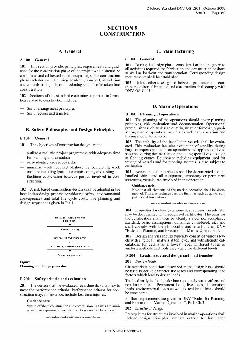
Offshore Standard DNV-OS-J201, October 2009 Sec.9 – Page 59
SECTION 9CONSTRUCTION
A. General
A 100 General101 This section provides principles, requirements and guid-ance for the construction phase of the project which should beconsidered and addressed at the design stage. The constructionphase includes manufacturing, load-out, transport, installationand commissioning; decommissioning shall also be taken intoconsideration.102 Sections of this standard containing important informa-tion related to construction include:
— Sec.3, arrangement principles— Sec.7, access and transfer.
B. Safety Philosophy and Design Principles
B 100 General101 The objectives of construction design are to:
— outline a realistic project programme with adequate timefor planning and execution
— early identify and reduce risks— minimise work required offshore by completing work
onshore including (partial) commissioning and testing— facilitate cooperation between parties involved in con-
struction.
102 A risk based construction design shall be adopted in theinstallation design process considering safety, environmentalconsequences and total life cycle costs. The planning anddesign sequence is given in Fig.1.
Figure 1 Planning and design procedure
B 200 Safety criteria and evaluation201 The design shall be evaluated regarding its suitability tomeet the performance criteria. Performance criteria for con-struction may, for instance, include lost time injuries.
Guidance note:Where offshore construction and commissioning times are mini-mised, the exposure of persons to risks is commonly reduced.
---e-n-d---of---G-u-i-d-a-n-c-e---n-o-t-e---
C. ManufacturingC 100 General101 During the design phase, consideration shall be given toall activities required for fabrication and construction onshoreas well as load-out and transportation. Corresponding designrequirements shall be established.102 Unless otherwise agreed between purchaser and con-tractor, onshore fabrication and construction shall comply withDNV-OS-C401.
D. Marine OperationsD 100 Planning of operations101 The planning of the operations should cover planningprinciples, risk evaluation and documentation. Operationalprerequisites such as design criteria, weather forecast, organi-sation, marine operation manuals as well as preparation andtesting should be covered.102 The stability of the installation vessels shall be evalu-ated. This evaluation includes evaluation of stability duringbarge transports and load-out operations and applies to all ves-sels used during the installation, including special vessels suchas floating cranes. Equipment including equipment used fortowing of vessels and for mooring systems is also subject toevaluation.103 Acceptable characteristics shall be documented for thehandled object and all equipment, temporary or permanentstructures, vessels, etc. involved in the operation.
Guidance note:Note that all elements of the marine operation shall be docu-mented. This also includes onshore facilities such as quays, soil,pullers and foundations.
---e-n-d---of---G-u-i-d-a-n-c-e---n-o-t-e---
104 Properties for object, equipment, structures, vessels, etc.may be documented with recognised certificates. The basis forthe certification shall then be clearly stated, i.e. acceptancestandard, basic assumptions, dynamics considered, etc. andshall comply with the philosophy and intentions of DNV“Rules for Planning and Execution of Marine Operations”.105 Design analysis should typically consist of various lev-els with a “global” analysis at top level, and with strength cal-culations for details as a lowest level. Different types ofanalysis methods and tools may apply for different levels.
D 200 Loads, structural design and load transfer201 Design loadsCharacteristic conditions described in the design basis shouldbe used to derive characteristic loads and corresponding loadfactors which lead to design loads.The load analysis should take into account dynamic effects andnon-linear effects. Permanent loads, live loads, deformationloads, environmental loads as well as accidental loads shouldbe considered.Further requirements are given in DNV “Rules for Planningand Execution of Marine Operations”, Pt.1, Ch.3.202 Structural designPrerequisites for structures involved in marine operations shallinclude design principles, strength criteria for limit state
DET NORSKE VERITAS

Offshore Standard DNV-OS-J201, October 2009 Page 60 – Sec.9
design, testing, material selection and fabrication.Requirements and guidelines are given in DNV “Rules forPlanning and Execution of Marine Operations”, Pt.1, Ch.4.203 Load transfer operationsThe load transfer operations cover load-out, float-out, lift-offand mating operations.Requirements to load transfer operations are given in DNV“Rules for Planning and Execution of Marine Operations”,Pt.2, Ch.1.Specific requirements and guidelines for single-vessel andbarge-towing operations are given in DNV “Rules for Plan-ning and Execution of Marine Operations”, Pt.2, Ch.2.
D 300 Offshore installation301 Specific requirements and recommendations for off-shore installation operations particularly applicable for fixedoffshore structures are given in DNV “Rules for Planning andExecution of Marine Operations”, Pt.2, Ch.4. Environmentalloads and load cases to be considered are described as well ason-bottom stability requirements and requirements to struc-tural strength.302 Operational aspects for ballasting, pile installation andgrouting shall be considered.303 Guidance and recommendations for well controlled lift-ing operations, onshore, inshore and offshore, of objects withweight exceeding 50 tonnes are given in DNV “Rules for Plan-ning and Execution of Marine Operations”, Pt.2, Ch.5. Thechapter describes in detail the basic loads, dynamic loads,skew loads and load cases to be considered.Design of slings, grommets and shackles as well as design ofthe lifted object itself are covered. In addition, operationalaspects such as clearances, monitoring of lift and cutting of seafastening are described.304 The requirements of the “International Regulations forPrevention of Collision at Sea” (COLREG) applicable to nav-igation lights and sound signals shall be complied with.305 Subsea cable tie-in and connection (including fibre opticcables) shall be considered at the design phase, including, forinstance, support of cable during installation and operation,location of pulling equipment and connection options likejunction boxes.
D 400 Subsea operations401 Subsea operations are relevant for tie-in of, for example,electrical cables. Planning, design and operational aspects forsuch installations are described in DNV “Rules for Planningand Execution of Marine Operations”, Pt.2, Ch.6.402 Diving operations shall be eliminated where practicable.
D 500 Warranty surveys501 Warranty surveys are normally required by the owner orby insurance companies for insurance of the sea transportphase and the installation phase.502 Warranty surveys are to be carried out in accordancewith an internationally recognised scheme, e.g. DNV “Rulesfor Planning and Execution of Marine Operations”. Marineoperations cover yard lift, load-out, sea transportation, off-shore lift and installation operations.
E. Documentation
E 100 Operational procedures101 Operational aspects shall be documented in the form ofcalculations, operation manuals and procedures.102 The documentation shall demonstrate that philosophies,principles and requirements of DNV “Rules for Planning andExecution of Marine Operations” are complied with.103 Documentation for marine operations shall be self con-tained or clearly refer to other relevant documents.104 The quality and details of the documentation shall besuch that it allows for independent reviews of plans, proce-dures and calculations for all parts of the operation.
Guidance note:A document plan describing the document hierarchy and scopeof each document is recommended for major marine operations.
---e-n-d---of---G-u-i-d-a-n-c-e---n-o-t-e---
105 Applicable input documentation such as:
— statutory requirements— rules— company specifications— standards and codes— concept descriptions— basic engineering results (drawings, calculations, etc.)— relevant contracts or parts of contracts
should be identified before any design work is performed.106 Necessary documentation shall be prepared to proveacceptable quality of the intended marine operation. Typically,output documentation consists of:
— planning documents including design briefs and designbasis, schedules, concept evaluations, general arrange-ment drawings and specifications
— design documentation including load analysis, globalstrength analysis, local design strength calculations, sta-bility and ballast calculations and structural drawings
— operational procedure including testing programme andprocedure, operational plans and procedure, arrangementdrawings, safety requirement and administrative proce-dures
— certificates, test reports, survey reports, NDE documenta-tion, as built reports, etc.
107 All relevant documentation shall be available on siteduring execution of the operation.108 Execution of marine operations shall be logged. Sam-ples of planned recording forms shall be included in the marineoperations manual.
E 200 As-built documentation201 The structural as-built documentation shall comprise:
— quality records, material test certificates, approval docu-ments
— construction procedures, method statements— construction log— inspection records, description of non-conformities— as-built drawings, description of accepted changes.
DET NORSKE VERITAS

Offshore Standard DNV-OS-J201, October 2009 Sec.10 – Page 61
SECTION 10IN-SERVICE INSPECTION AND MAINTENANCE
A. General
A 100 General101 This section provides principles, requirements and guid-ance for the inspection and maintenance system to be consid-ered at the design stage, covering the entire installation fromsupport structure to the topsides and the subsea cable inter-faces.102 Sections of this standard containing important informa-tion related to in-service inspection and maintenance include:
— Sec.3, accessibility for inspection and maintenance— Sec.8, test of emergency response systems.
B. Safety Philosophy and Design Principles
B 100 General101 The objectives of in-service inspection and maintenancedesign are to:
— ensure that the offshore substation remains suitable for itsintended purpose throughout its lifetime
— outline requirements and recommendations for in-serviceinspection, maintenance and condition monitoring of off-shore substations
— indicate how these requirements and recommendationscan be achieved.
102 A risk based, in-service inspection and maintenance pro-gramme shall be established as part of the design process con-sidering safety, environmental consequences and total lifecycle costs.
B 200 Design basis201 Development of an in-service inspection and mainte-nance programme shall be based on information such as:
— applicable codes and standards— manufacturer required inspection and maintenance scope
and frequency— target lifetime of structure, systems and components— site conditions, see Sec.4 B300— deterioration processes— knowledge based on design and technology— experience gained from similar installations; historical
inspection and maintenance data— access and transfer options, see Sec.7.
B 300 Design process301 Risk based inspection and maintenance should be basedon the expected life of the system and entails a comprehensiveanalysis of the system, planning of inspection and maintenanceactivities, execution and feedback for improvement.302 The process involves screening of the system regardingits risks (Fig.1). Low risk items may be subject to correctivemaintenance strategies. High risk components should be eval-uated further based on their type. Risk based inspectionsshould be chosen for items whose integrity is expected to grad-ually deteriorate. Safety critical equipment should be subject tosafety based inspections and maintenance. Risk based mainte-
nance addressing reliability should cover the remaining equip-ment and items.
Figure 1 Risk based maintenance concept
303 Based on the system assessment, a long-term inspectionand maintenance programme shall be established. The plansshould specify:
— scope and frequencies of work— requirements for inspection and maintenance manuals— requirements for conditioning monitoring systems— requirements with respect to personal safety.
304 Based on findings, historical data, experience and newknowledge and techniques, the programme scope and timingshall be periodically reviewed and updated. Special attentionshould be paid to deterioration mechanisms for the relevantmaterials and components such as:
— time-dependent effects— mechanical/chemical attacks— damage from accidents.
Guidance note:In offshore wind farms the interval between inspections of criti-cal items does normally not exceed one year. The entire windfarm is normally inspected at least once during a five-yearperiod. Intervals for subsequent inspections are adjusted basedon findings.
---e-n-d---of---G-u-i-d-a-n-c-e---n-o-t-e---
305 Where necessary, inspection intervals shall be adjustedto comply with legal requirements and project conditions or tomeet equipment manufacturers’ recommendations.
DET NORSKE VERITAS

Offshore Standard DNV-OS-J201, October 2009 Page 62 – Sec.10
C. Risk Based Inspection and Maintenance
C 100 General101 Personnel involved in inspection planning and conditionassessment shall have relevant competence with respect to theoffshore substation design, materials, construction and specificexperience in the application of inspection and maintenancetechniques. Service staff shall familiarise themselves with theprimary design and operational aspects before conducting aninspection.102 The first inspection and condition verification shall pro-vide a comprehensive initial assessment. Thereafter, the activ-ities shall be carried out periodically in accordance with therisk based maintenance programme.103 Following the inspection and maintenance activities andevaluation of the condition shall be carried out. Trends indicat-ing time-dependent deterioration processes shall be evaluated.104 Inspection and maintenance activities shall be consid-ered after direct exposure to extreme environmental events(e.g. extreme waves) and accidental events (e.g. boat colli-sion).105 In the event of change of use, lifetime extension, modi-fications, deferred abandonment, damages or deterioration ofthe offshore substation or a notable change in the reliabilitydata on which the inspection and maintenance scheme isbased, measures shall be taken to maintain the substationintegrity, safety and reliability. The programme shall bereviewed to determine the applicability to the changed condi-tions and shall be subjected to modification as required.
D. Scope of Service
D 100 Types of service101 Inspection and maintenance activities include:
— global and close visual inspection— non-destructive inspection/testing— instrumentation based condition monitoring— corrective maintenance.
D 200 Structural components201 Structural surveys focus for components above waterfocus on:
— dents and deformation— fatigue cracks— bolt pre-tension— corrosion— marine growth,
and include components such as:
— foundation structure— platform decks, walls and appurtenances— walkways, stairs, ladders— J-tubes, fenders, pipework— lifting appliances— helicopter deck.
202 Inspection of structures in the splash zone and belowwater focuses in addition on the corrosion protection systems(steel wall thickness, anodes, coating, etc.) and scour protec-tion.
D 300 Electrical and control system301 The following items shall be covered by the inspection:
— main and auxiliary transformer(s)— high and medium voltage switchgear— emergency power generation equipment (diesel generator,
batteries, UPS)— auxiliary power supply, HVAC equipment and similar
facilities— cables— earthing system— measurement, monitoring, control (parameters and set-
tings) and protection systems.
302 Subsea cables connected at the offshore substation shallbe inspected for proper fixing and signs of wear. Cable burialto design depth shall be verified.
D 400 Fire protection systems401 Inspection, maintenance and tests of fire protection sys-tems shall, as a minimum, be carried out in accordance withapplicable regulations.
Guidance note:Portable extinguishers commonly require annual inspections.
---e-n-d---of---G-u-i-d-a-n-c-e---n-o-t-e---
D 500 Helidecks501 The helicopter deck shall be monitored and kept freefrom oil, grease, snow, ice, surface water and other contami-nants such as guano which could degrade surface friction orcompromise visibility of markings.
Guidance note:Regular friction tests may be prescribed by the authority.
---e-n-d---of---G-u-i-d-a-n-c-e---n-o-t-e---
502 Further inspection shall be carried out for the followingdeck landing area components:
— landing net— perimeter safety netting— tie-down points— wind indicator— perimeter and flood lighting— fuel system installation and earthing.
D 600 Safety and emergency response system601 The following items shall be covered by the inspection:
— emergency lighting— communication systems— rescue equipment— fall arrest systems— personal safety and protection equipment— markings, warnings and identification panels.
E. Documentation
E 100 General101 The results of in-service inspections and maintenanceshall be reported. The efficiency and integrity of the inspectionand condition monitoring activities is dependent on the valid-ity, timeliness, extent and accuracy of the available inspectiondata.102 Up-to-date inspection and maintenance reports and sum-maries shall be retained.
DET NORSKE VERITAS

Offshore Standard DNV-OS-J201, October 2009 App.A – Page 63
APPENDIX A RISK MANAGEMENT CONCEPTS
A. Hazards and RiskA 100 General101 A hazard is a potential source of harm. Harm may berelated to human injury, negative environmental impact, dam-age to property or a combination of these. An incident whichoccurs when a hazard is realised is a hazardous event or a fail-ure.102 Risk is the likelihood of a specified undesired eventoccurring within a specified period or in specified circum-stances. It can be expressed as the combination of probabilityand consequence of that event.
B. Consequence of FailureB 100 General101 Consequence of failure (CoF) is evaluated as the out-come of a failure based on the assumption that such a failurewill occur.102 Consequence of failure values or rankings should bepresented separately depending on the consequence type:
— health and safety— environmental impact— economics— loss of reputation.
103 The consequence scale is necessarily different for differ-ent types of consequence and should be selected to account forthe full range of values.
B 200 Health and safety consequences201 Safety consequence evaluation should take into accountimportant factors such as:
— fires and explosions— toxicity— falling from heights.
202 Safety consequences should consider the potential deathand injury of personnel and are commonly expressed in termsof potential loss of life (PLL).203 An example of a safety consequence scale is shown inTable B1 with ranges from very low (LL) to very high (HH).
204 When estimating safety consequence, the changes inmanning levels that occur as a result of different phases ofoperation shall be considered.
B 300 Environmental consequences301 Environmental consequence analysis requires estima-tion of factors such as:
— pollution through discharge of liquids— gas releases, also regarding greenhouse potential
— loss of highly toxic chemicals— excessive noise.
302 Environmental consequences should consider local andglobal damage to the environment alone; not including safetyand economic aspects.303 An example for an environmental consequence scale isshown in Table B2. The definition of units (financial, volumet-ric) depends on the design philosophy.
B 400 Economic consequences401 Economic consequence should consider all mattersfinancial in relation to a potential incident including:
— repair costs— clean-up costs— value of lost production— fines.
402 Economic consequence should be expressed in financialterms using appropriate currency units.403 An example of an economic consequence scale is shownin Table B3, assuming an installation value of 25 M€.
404 The economic consequences of business interruptioncan be estimated from duration and extent of production down-time, multiplied by the value of production.
C. Probability of Failure
C 100 General101 Probability of failure (PoF) is the probability of an eventoccurring per unit time (e.g. annual probability).102 An example of a probability of failure scale is shown inTable C1.
Table B1 Safety consequence scaleCategory CoF (PLL) Description
HH > 1 multiple fatalitiesH 1 single fatalityM 10-1 major injury, permanent disabilityL 10-2 minor injury
LL 10-3 slight injury
Table B2 Environmental consequence scaleCategory CoF (litres of oil) Description
HH > 16 000 massive effectH 10 000 to 16 000 major effectM 1 000 to 10 000 local effectL 100 to 1 000 minor effect
LL < 100 slight effect, negligible
Table B3 Economic consequence scaleCategory CoF (€) Description
HH > 5 M massive effectH 500 k to 5 M major effectM 50 k to 500 k local effectL 5 k to 50 k minor effect
LL < 5 k slight effect, negligible
Table C1 Probability of failure scaleCategory PoF / year Description
HH > 10-2 failure expectedH 10-3 to 10-2 highM 10-4 to 10-3 mediumL 10-5 to 10-4 low
LL < 10-5 failure not expected
DET NORSKE VERITAS

Offshore Standard DNV-OS-J201, October 2009 Page 64 – App.A
D. Risk PresentationD 100 General101 Risk is conveniently presented as a matrix. A separatematrix for each consequence type should be defined.102 The common risk matrices shall be harmonised andstandardised at the beginning of the design process and usedfor all risk assessments related to the installation under review.103 To achieve adequate resolution, a 5 × 5 matrix is recom-mended as shown in Fig.1. All matrices should use the com-mon probability scale on one (normally the vertical) axis andindividual consequence scales on the other (normally the hori-zontal) axis.104 The risk is commonly divided into three or four (pic-tured) categories which should be the same for safety, environ-mental and economic aspects:
— H: High risks are unacceptable and actions shall be takento reduce the risk level
— M: Medium risk can be further divided into tolerable(upper) and broadly acceptable (lower) regions to focusefforts for risk controla) Risks are tolerable once all reasonably practicableactions have been taken to reduce them. Further reductionaction is needed, unless the costs are grossly dispropor-tionate to the benefits.b) Risks are broadly acceptable if most people would notbe concerned by them. Further action is appropriate where
cost-effective, or where needed to ensure risks do notincrease.
— L: Low, negligible risks do not require actions to be taken.
105 A matrix with three categories can be divided into H =unacceptable, M = tolerable with action required and L =broadly acceptable with no action required.
Figure 1 Example of a risk matrix
DET NORSKE VERITAS

Offshore Standard DNV-OS-J201, October 2009 App.B – Page 65
APPENDIX B HAZARD IDENTIFICATION
A. Potential Offshore Substation HazardsA 100 General101 Table A1 provides examples for hazardous events which
may be encountered on offshore substations, possible causesand consequences. Potential consequences are given for(P)eople, (E)nvironment and (A)sset.
Table A1 Hazard identification for offshore substations
Number Hazardous event Possible causes Possible consequences1 Structural incident1.1 Structural damage Ship impact
Transformer explosionFire in sump tankExtreme weatherSubsidenceScouringEarthquakeSubsea/splash zone corrosion
Fatality (P)Platform collapse (A)
1.2 Collision of vessel with platform Loss of powerInappropriate approach procedure/designHuman factorsAdverse weather or sea stateLack of navigation aidsDrifting vessel
Structural damage (A)
1.3 Dropped object, swinging load Inappropriate liftingHuman errorAdverse weatherSling whole or partial failureMechanical failure
Injury, fatality (P)Damage (A)
2 Electrical incident2.1 High voltage faults Connection point
Short circuitInjury (P)
2.2 Short circuit in electrical installations Poor maintenanceSubstandard components/cablesPoor design
Fire, explosion (A)
2.3 Release of SF6 Fault operationSystem failureSystem design
Injury, narcosis, asphyxia (P)Greenhouse gas release (E)
2.4 Electrocution, electric shock Maintenance activitiesUntrained personnelTouch voltagesLack of high voltage signage
Injury, fatality (P)
2.5 Unattended electrical consumer Failure to switch off electrical consumers Fire (A)2.6 Failure of lightning protection Inadequate earthing
Incorrect designPoor maintenance
Fire, explosion (A)
2.7 Electromagnetic compatibility problem Electromagnetic radiation from equip-ment
Health risk (P)Interference (A)
2.8 Loss of emergency power Start failure of generatorDiesel shortageBattery or UPS failure
Shutdown of emergency consumers (A)
2.9 Fuel release from emergency generator, day tank or storage tank
Loss of containmentPipe, valve or hose failureHuman error
Pollution (E)Fire (A)Loss of emergency power (A)
2.10 Hydrogen release from batteries Collapse of cellsLack of ventilationCharging failure
Injury (P)Explosion (A)
2.11 Battery leakage Structural failureAged batteriesPoor maintenanceCharging failure
Injury (P)
DET NORSKE VERITAS

Offshore Standard DNV-OS-J201, October 2009 Page 66 – App.B
3 Fire and explosion incident3.1 Main transformer fire or explosion Internal fault
Short circuitLack of cooling mediumOil degradationExternal fireOverloadPoor layout or design
Injury, fatality (P)Release of burning oil (E)Downtime (A)
3.2 Utility transformer fire Internal faultShort circuitLack of cooling mediumExternal fireOverload
Injury (P)Downtime (A)
3.3 HV switchgear fire or explosion Lack of insulation gas (SF6)Earthing faultShort circuitOverloadMalfunction of equipmentPoor maintenanceLack of trainingIncorrect work procedures
Injury (P)Downtime (A)
3.4 LV equipment fire Short circuitOverloadMalfunction of equipment
Injury (P)Downtime (A)
3.5 Emergency generator fire Internal faultGenerator allowed to run out of fuelFuel system leakPoor maintenance
Injury (P)Environmental pollution (E)Loss of emergency power (A)
3.6 Toxic smoke Fire on transformer or electrical equip-mentExplosionLoss of containment
Injury (P)Damage (A)
3.7 Fire in accommodation Kitchen or cabin useSmokingPoor housekeepingUnattended electrical equipment
Injury, fatality (P)
3.8 Fire or explosion at helicopter deck Ignited leak or static discharge Injury (P)4 Access and transfer incident4.1 Marine transfer incident Slips, falls caused by marine growth, ice
Ladder failure caused by marine environ-mentLack of instruction & training
Injury (P)
4.2 Helicopter crash, ditching Mechanical failurePilot errorPoor weather/visibilityLoss of fuel
Injury, fatality (P)Helicopter/installation damage (A)
4.3 Helicopter rotor impact Lack of training or controlPoor housekeepingLack of helideck protection (nets, lights, etc.)Adverse weather
Injury, fatality (P)Helicopter/installation damage (A)
4.4 Helicopter winching incident Poorly controlled winchingMechanical failure of winching systemPoor weather
Injury, fall, fatality (P)Helicopter damage (A)
4.5 Unauthorised access to high risk area Lack of locks, signage Injury (P)Tampering with equipment (A)Release (E)
5 Emergency response incident5.1 Man over board Boat transfer
Maintenance workPersonnel working over water
Injury, fatality (P)
5.2 Loss of escape route or transfer back to shore
Inclement weatherNearby marine emergencyNo ERRV due to other workMechanical problems with vessel
Being stranded, injury (P)
5.3 Loss of communication to vessels or shore
Cable or equipment faultOnshore problemLoss of powerFire, explosionMaintenance activities
Delays (P)
Table A1 Hazard identification for offshore substations (Continued)Number Hazardous event Possible causes Possible consequences
DET NORSKE VERITAS

Offshore Standard DNV-OS-J201, October 2009 App.B – Page 67
5.4 Failure of flood lights, navigation aids Loss of power Unsafe operations (P, A)5.5 Shortages in food and water supply Poor planning
Inclement weatherDiscomfort, injury (P)
5.6 Uncoordinated search and rescue Poor proceduresLack of equipmentLack of trainingLanguage
Delays, injury, fatality (P)
6 Other incidents6.1 Release from cooling oil system Loss of containment Injury (P)
Contamination (E)Downtime (A)
6.2 Failure of HVAC system Wrong designMalfunctioning of fire dampersFailure of detector
Smoke ingress into cabins (P)Feeding fire with oxygen (A)
6.3 Occupational hazards Vessel movementAdverse weather and sea states
Injury (P)
Table A1 Hazard identification for offshore substations (Continued)Number Hazardous event Possible causes Possible consequences
DET NORSKE VERITAS

Offshore Standard DNV-OS-J201, October 2009 Page 68 – App.B
DET NORSKE VERITAS