Embed Size (px)
Citation preview

DNV Container Ship UpdateInformation from DNV to the Container Ship industry No. 1 April 2010
QUANTUMa container ship
concept for the future
Also inside:� Industry questionnaire� LNG in focus� Increased container capacity
Quantum
SPECIAL EDITION

Machinery and ship systems – a flexible solution for an uncertain future
General arrangement and LNG tank arrangement
CONTENTS
2 | DNV CONTAINER SHIP UPDATE NO. 1 2010
DNV Container Ship Updateis a newsletter published by Det Norske Veritas, DNV Maritime.It is distributed to DNV customers and stations worldwide.
© Det Norske Veritas AS
Please direct any enquiries to your nearest DNV station or Container Ship Update e-mail: [email protected]
Editorial committee:Business Director Container Ships: Vebjørn J. GuttormsenEditor: Magne A. RøeAssociate Editor: Knut A. DøhlieProduction: Cecilie JohansenDesign: Coor Graphic Services 1001-011Printing: 07 Oslo AS, 6,000/3-2010
Online edition of DNV Container Ship Update:http://www.dnv.com/containerupdate
DNV (Det Norske Veritas AS)NO-1322 Høvik, NorwayTel: +47 67 57 99 00Fax: +47 67 57 99 11
An updated list of all regional offices can be seen on DNV’s website: www.dnv.com
WE WELCOME YOUR THOUGHTS!
DNV ContainerShip Update
QUANTUM, THE CONCEPT . . . . . . . . . . . . . . . . . . 4
CHAPTER 1: MARKET NEEDS . . . . . . . . . . . . . . . . 10
CHAPTER 2: HULL DESIGN . . . . . . . . . . . . . . . . . 20
CHAPTER 3: MACHINERY AND SHIP SYSTEMS . 40
CHAPTER 4: OPERATION . . . . . . . . . . . . . . . . . . . 50
CHAPTER 5: INDUSTRY FEEDBACK . . . . . . . . . . 58
Quantum – a container ship conceptfor the future ›› ›› ››
04 24 40
Front cover: An artist’s impressionof the Quantum concept.
Quantum
Illustrations: front cover ©Octaga, MAN, p3 ©Octaga, MAN, p5–6 ©Octaga, MAN, p8 ©DNV/Eirik Byklum, p9 ©DNV/Magne A. Røe,p12 ©DNV/Knut A. Døhlie, p16–17 ©Octaga, MAN, p31 ©Octaga, MAN,p32–33 ©DNV/Magne A. Røe, p35 ©Octaga, MAN, p40 ©Octaga, MAN,p43 ©ABB, p48–49 ©DNV/Magne A. Røe, p59 ©DNV/Knut A. Døhlie,p61–63 ©DNV/Magne A. Røe, back cover ©Octaga, MAN

DNV CONTAINER SHIP UPDATE NO. 1 2010 | 3
EDITORIAL
Vebjørn J. GuttormsenBusiness DirectorContainer Ships
NEXT GENERATION CONTAINER SHIPS
Artist’s impression of the 6,210 TEU Quantum.
We are proud to introduceQuantum. An innovativecontainer ship conceptdeveloped by DNV with aview to the future of con-tainer shipping. In thismagazine you can readabout the project and thedesign rationale behindthe concept study. Wehope this will be a sourceof inspiration that can giveyou ideas to better ‘future-proof’ your fleet invest-ments.
The change in the globaleconomy and increasedglobal environmental con-
cerns mean that shippingis facing a new reality. Ves-sels ordered today will bein operation for the next25–30 years and decisionsmade today will determineyour market position inthe years to come.
So what are the challengesin this new reality? Whatwill the design speed be?In the long term, the oilprice is expected toremain high and to keepon increasing. A tax oncarbon emission will prob-ably be introduced. Shouldwe design for the current
super-slow steaming speed,or will the speed return tonormal when the marketrecovers?
DNV put together a teamof its own experts from var-ious disciplines to look atthe technology and solu-tions that are expected tobe available in a three tofive year perspective. Mar-ket studies were carriedout by AXS Alphaliner andDynamar B.V. to examinethe outlook for and futuredevelopments in the con-tainer trades. A loop fromEurope to East Coast
South America was chosenas a basis for this project.
The result is Quantum, aconcept container shipdeveloped by DNV to testnew ideas and future-ori-ented solutions. Flexibilityhas been the answer in aworld of uncertainty. Webelieve this is a prudentstrategy for a future inwhich we will have to adaptto market changes andenvironmental legislationthat are not yet known tothe industry.
››

Quantum – a container ship concept for the future
Quantum has been designed to transport more cargo while using less fuel and withreduced environmental impact. The focus has been on flexibility in a future of uncertainty,
while also ensuring efficient and reliable operations.
TEXT: EIRIK BYKLUM AND KNUT A. DØHLIE
MARKET NEEDS� Choice of ship and features based on
market studies by AXS Alphaliner andDynamar
� ‘Baby post-Panmax’ of 6,200 TEU witha high reefer capacity of 1,200 plugsdesigned for flexible operations
� The design is suitable for future tradebetween Europe and the East Coast ofSouth America
� A ship size with features likely to beamong the first to be built in the nextordering wave, with technology that isavailable today
� Design speed of 21 knots with the abil-ity to boost speed by several knots andslow steam down to less than 10 knots
� A design with a commercial life for thecoming decades. Legislation to come,but not yet known, may be bettercatered for due to the built-in flexibili-ty. Power converters may be exchangedfor newer technology (e.g. fuel cells)without redesigning the plant
� The increased capital expenditure willbe offset by improved operating costsand trading flexibility
QUANTUM
4 | DNV CONTAINER SHIP UPDATE NO. 1 2010
››Quantum midship section.
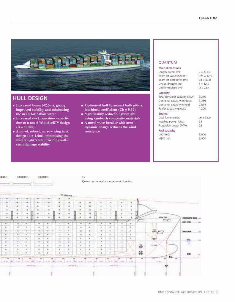
HULL DESIGN� Increased beam (42.5m), giving
improved stability and minimisingthe need for ballast water
� Increased deck container capacitydue to a novel WidedecK™ design (B = 49.0m)
� A novel, robust, narrow wing tankdesign (b = 1.0m), minimising thesteel weight while providing suffi-cient damage stability
� Optimised hull form and bulb with alow block coefficient (Cb = 0.57)
� Significantly reduced lightweightusing sandwich composite materials
� A novel wave breaker with aero -dynamic design reduces the windresistance
QUANTUM
DNV CONTAINER SHIP UPDATE NO. 1 2010 | 5
QUANTUM
Main dimensionsLength overall (m): L = 272.3Beam (at waterline) (m): Bwl = 42.5Beam (at deck level) (m): Bd = 49.0Design draught (m): T = 12.0Depth moulded (m): D = 26.4
CapacityTotal container capacity (TEU): 6,210Container capacity on deck: 3,336Container capacity in hold: 2,874Reefer capacity (plugs): 1,200
EngineDual fuel engines: L6 + 3xL9Installed power (MW): 33Propulsion power (MW): 23
Fuel capacityLNG (m3): 5,000MDO (m3): 3,000
››Quantum general arrangement drawing.
QUANTUM
6 | DNV CONTAINER SHIP UPDATE NO. 1 2010
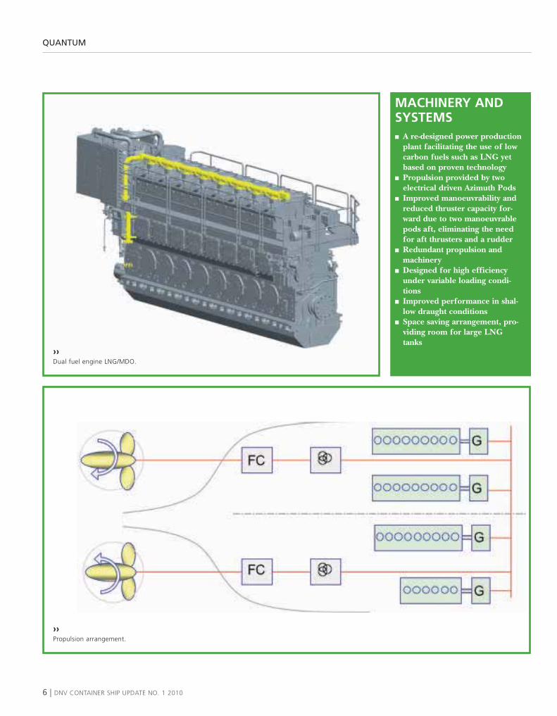
MACHINERY ANDSYSTEMS� A re-designed power production
plant facilitating the use of lowcarbon fuels such as LNG yetbased on proven technology
� Propulsion provided by twoelectrical driven Azimuth Pods
� Improved manoeuvrability andreduced thruster capacity for-ward due to two manoeuvrablepods aft, eliminating the needfor aft thrusters and a rudder
� Redundant propulsion andmachinery
� Designed for high efficiencyunder variable loading condi-tions
� Improved performance in shal-low draught conditions
� Space saving arrangement, pro-viding room for large LNGtanks
››Propulsion arrangement.
››Dual fuel engine LNG/MDO.

QUANTUM
DNV CONTAINER SHIP UPDATE NO. 1 2010 | 7
OPERATION
� Flexible engine arrangement –four-stroke engines, either dualfuel (LNG/diesel) or a selectionof dedicated energy converters
� LNG fuel for auxiliary power inECA areas and partly for propul-sion. LNG storage tanks provid-ed above the engine room area,allowing maximum containercapacity
� Environmentally friendly andprepared for future regulations
� LNG is proven in service onfour-stroke engines, while two-stroke engines for LNG do notyet have a track record
� A novel ‘block loading’ devicewith eight empty or lightweightcontainers has been introduced,increasing loading efficiencyand cargo safety by connectingstacks at the top tier
[email protected]@dnv.com
››Layout of LNG tanks.
››Five stages of concept development (see page 24).

The Quantum project– thinking outside the box
What is the future of container shipping? Can we develop an innovative container ship conceptwithin a short period of time and design a ship with improved operational and environmental
performance? The answer to these questions was the Quantum concept.
TEXT: EIRIK BYKLUM
DEFINING THE FUTUREIn order to take on this challenge, a systematicwork process was needed. It is important todecide on a business case and identify the criti-cal needs before jumping to technical solu-tions. We found it useful to divide the projectinto three phases:
� Phase 1 – Business case: Market and transport system analysis
� Phase 2 – Industry needs: Identify critical industry needs and alterna-tive solutions
� Phase 3 – Development: Concept and design development, verification analyses
How we define the ‘future’ is an importantconsideration. Many alternative concepts havebeen proposed, but they often look 20–30 yearsinto the future. We found it more useful tolook at what we can do in the next few yearsusing the best available technology. We are in aperiod with difficult market conditions and lit-tle ordering of newbuildings but steadilyincreasing environmental awareness. This is theright time to develop new designs. With that inmind, we decided on a time perspective of 3–5years. This ruled out more long-term solutionssuch as fuel cells, while introducing LNG intothe fuel mix was found to be feasible.
REDUCED DESIGN SPEED, INCREASED FLEXIBILITYThe project’s first step was to consider thecontainer ship market with respect to trendsin ship size, speed and trade in order to iden-tify an adequate business case. The5,000–7,500 TEU segment was chosen as
there are a number of growing economiesand emerging trade lanes that will require rel-atively smaller, more compact ships with fea-tures such as shallow draft and high reefercapacity. The Europe – East Coast of SouthAmerica trade was chosen as an example of atrade which is assumed to have a strongfuture growth potential.
A transport system analysis was carried outin order to identify critical design require-ments for the size segment and trade underconsideration. From the operational profile, itwas found that large variations must be expect-ed during operation and that flexible solutionsshould be sought. A sensitivity analysis withrespect to design speed was also carried out.Not surprisingly, it was found that lowering thedesign speed is a very effective way of reducingthe operational costs and environmentalimpact. Some fear that ships with lower designspeed may be less attractive when the marketconditions improve. However, as a return tocheap oil seems unlikely and consumers’ envi-ronmental concerns are continuously increas-ing, we believe that a shift to lower designspeeds is the right way to go in the future.
NEEDS FIRST, THEN SOLUTIONS Workshops and brainstorming sessions wereused to define the critical Needs and identifyrelevant Solutions to meet the Needs. Thefocus was on solutions that can improve theperformance with respect to operational effi-ciency, fuel consumption, cost and environ-mental performance. Innovative solutionswere considered within areas such as hulldesign, machinery systems, propulsion sys-tems, materials, cargo handling and opera-tional efficiency, and the solutions were inves-tigated with respect to market adaptability,fabrication adaptability and fitness for pur-
THE QUANTUM PROJECT
8 | DNV CONTAINER SHIP UPDATE NO. 1 2010
››Eirik Byklum, Quantum ProjectManager.

THE QUANTUM PROJECT
DNV CONTAINER SHIP UPDATE NO. 1 2010 | 9
››More than 30 people contributed to the project. Here represented by (front row, from left) Arne Færevaag, Gaute Storhaug, Gabriele Mazza, Eirik Byklum, YangZhang, Harald Bergsbak, Ivar Håberg, (back row, from left) Nenad Dadic, He Jiang, Kristoffer Brinchmann, Terje Theien, Christian Andersson, Krzysztof Jankowski,Erik Brodin, Knut A. Døhlie, Atle Ellefsen, Morten Kristmoen, Vebjørn Guttormsen.
pose. A customer survey was used to evaluate the needsand alternative solutions.
Some selected solutions were then chosen for furtherinvestigation with respect to technical and economic fea-sibility. The solutions were not only to look innovativebut should also demonstrate real improved perform-ance. During this process, many ‘innovative’ conceptssuch as catamaran and trimaran hulls were discarded. Inthe end, the most promising concept was selected forinitial concept development, which was followed bydetailed technical development as well as verificationanalyses.
Finally, although this project mostly focused on design,the operational side should not be forgotten. This is anarea where great savings are achievable, and work was alsocarried out to evaluate various solutions for increasing theoperational performance.
We have called our concept Quantum. You can read alot more about it in the following articles.
››Work in progress. From left: Knut A. Døhlie, Eirik Byklum, Atle Ellefsen, He Jiang, Yang Zhang, Christian Andersson.

Market potential for a new container ship design
A ‘baby post-Panmax’ may be one of the first ships ordered when the newbuildingmarket recovers. The 5,000–7,500 TEU range may be the new workhorse of the industry
according to a market analysis by Alphaliner prepared for DNV. The Quantum conceptdesign is intended for the Europe to East Coast South America trade.
TEXT: MORTEN KRISTMOEN
The market analysis is based on variousitems of information, the majority providedby Alphaliner and Dynamar, both of whichare recognised and respected providers ofshipping market intelligence.
THE CONTAINER SHIP NEWBUILDINGPROGRAMME IS UNEVENLY SPREADOVER THE SIZES During the couple of years prior to thefinancial crisis starting in the 2nd half2008, the shipping industry experiencedever increasing ordering activity. Howev-er, the order book is not evenly spreadover the segments but rather more domi-nated by the larger sizes. A massive waveof orders for 10,000+ TEU ships accountsfor a large portion of the expectedincrease in capacity. The trend towardsemploying bigger and bigger ships ontrades servicing growing economies andemerging trade lanes faces one majorchallenge.
MARKET DEMAND, PORT INFRASTRUCTURE AND RESULTING SHIP REQUIREMENTS As ship sizes increase, so do the require-ments as to port facilities and capabilities.This is particularly the case with regard todraft restrictions, length restrictions andthe crane outreach and lifting capacity.
Even though there are many ports in theemerging markets and growing economiestoo that are well capable of servicing eventhe biggest of ships, there are still a numberof ports that will have challenges and limita-
10 | DNV CONTAINER SHIP UPDATE NO. 1 2010
EXISTING ANDEMERGING MARKETSOFFER OPPORTUNITIESFOR NEW DESIGNS
UNITED STATESIMPORTUS has suffered the mostfrom the present crisis,but is also expected torecover the quickest.Import from SouthAmerica is expected toincrease.
SOUTH AMERICANEXPORT & IMPORTLarge economies expectedto grow fast, leading toincreased imports ofconsumer goods. Alsohigh export volumes fromthis area, particularlyperishable goods in reefercontainers.
CHAPTER 1: MARKET NEEDS

tions for a considerable time to come. We thus foresee a market potential in
the 5,000–7,500 TEU segment, as there area number of growing economies andemerging trade lanes that will require rela-tively smaller, more compact ships with fea-tures such as shallow draft and high reefercapacity. One example of this is the tradeto and from the east coast of South Ameri-ca. This trade is assumed to have a strongfuture growth potential and is likely torequire shallow draft ships in many of theports along the cost. Furthermore, thistrade is expected to require ships with ahigh intake of reefer containers, as thereare substantial exports of fruit, meat andother perishable goods.
The list of ships ordered in the 5,000–7,500 TEU segment is also substantial, but itis dominated by ships at the upper end ofthis segment and often with relatively stan-dard designs. The number of newbuildingsat the lower end, i.e. around 5,500 TEUwith a high reefer intake and a shallowdraft, is limited. These ships have severaldeployment options on both the establishedand emerging trade lanes (includingthrough the new Panama Canal) and couldbecome the industry’s new ‘workhorse ships’ over the next few years. They will behighly relevant for both intercontinentaltrades, especially trades to and from Africaand South America, and large feeder routessuch as the ‘Intra Persian Gulf’ trade.
DNV CONTAINER SHIP UPDATE NO. 1 2010 | 11
“Ships in the 5,500 TEU region may become thenew ‘workhorse’ of the industry,” says Alphaliner
MIDDLE EASTERNIMPORTHigh activity within oiland gas, and prosperity insociety in general impliesincreased demand forconsumer goods – andthrough that increaseddemand for containerfreight and intra-regionalfeedering.
INDIAN EXPORTOn the back of arecovered world economy,export from India toEurope and US is expectedto increase significantly.Ships of up to VLCS sizecan be utilised.
CHAPTER 1: MARKET NEEDS

An innovator or only an inventor?
When companies try to innovate, many of them end up inventing instead. What’s thedifference between innovation and invention, and what does it mean for my company?This is one of several questions we face as innovators. ‘What shall I do to succeed with
innovation in my project’ or simply ‘How do I start’, are other commonly asked questions.I’ll give you some answers a little bit further down the page.
TEXT: SJUR DAGESTAD
DNV is focusing on containership inno-vation in order to create new andimproved solutions. The team tries toavoid all the traps that can make theproject end up with nothing (except forwasted time and money). Typically, com-panies and project teams tend to go forsolutions way too early. Through theyears, we’ve seen companies that havestarted making solutions before theyeven know what to solve.
This is the Inventor’s dilemma; mak-ing solutions, gadgets or things thatnobody needs. The difference betweenan inventor and an innovator is that theInnovator manages to create value forthe customer. Inventors typically createsolutions for themselves.
Another major mistake developersmake is to identify themselves as the cus-tomer. Many developers have given birthto new solutions according to the philos-ophy that: ‘I want to have this, thuseverybody else also wants to have it’.
CUSTOMER NEEDSWhen we consult companies, we typicallyexperience that they lack a deep insightinto their customers’ needs (N). Howev-er, some of the same companies havestrong, almost religious, opinions onwhat the solution (S) should be. This iswhat we call a small N and large red Sfocus.
Winners in the marketplace tend tohave a large N and medium-sized Sfocus. A medium S can be modified, a
large red S is not easy to change. Justthink about it in your own setting. Howmany times have you met a supplier whowants to sell you a big red S which doesnot really meet your need?
Wish: N S
Reality: N SSo what should you do? First of all, thecustomer has the solution. Normally thecustomer doesn’t know what the futurewill look like but yet still knows it.
Good developments start with goodneeds. Bad developments start with abrilliant idea.
This might sound provocative, butlet’s take a look at a small investigationcarried out by three gentlemen (Golden-berg, Lehmann and Mazursky) at TheMarketing Science Institute in 1999.They looked at 197 solutions of which111 were successes and 86 were failures.Those who based their solution on a bril-liant idea, ended up with a success in28% of the cases. On the other hand,those who based their solution on a mar-ket need and created a solution to meetthis need, ended up with a success in69% of the cases.
12 | DNV CONTAINER SHIP UPDATE NO. 1 2010
››Sjur Dagestad, Professor in Innovation at theNorwegian University of Science and Technology(NTNU). Partner in the innovation companyInnoco AS.
CHAPTER 1: MARKET NEEDS

INNOVATION MODEL In the US, a company called Doblin hasstudied a vast number of innovations. Itlooked into the innovation projects,studying what and where innovationtook place. Based on these studies, ithas created ten categories for innova-tion in companies. That means that typ-ically, when we innovate, we work with-in one or several of these categories orboxes. When your company works onproduct development, you only workwithin two of the ten boxes. Why limityourself to two when you can have ten?
One of the first things we did in the
containership project was to make surethat all the team members got them-selves out of the inventor trap and start-ed thinking as innovators. The wholeproject worked with all ten categories ofinnovation instead of only the two cate-gories of product development. SmallNs, Big Ns, Red Ss and shapable Ssbecame a part of the project’s compe-tence. We also looked at where money isbeing spent and where money is earnedin innovation projects. The reason forthat is of course to put the effort wherethe money is.
If you’re still reading, you might be
wondering what the ten categories ofinnovation are. These are: businessmodel, network and alliances, enablingprocess, core process, product perform-ance, product system, service, sales chan-nel, brand and, last but not least, cus-tomer experience.
And remember: if you always do whatyou always did, you’ll always get what youalways got. This is almost true. The realtruth is that you’ll get less. That meansothers get more. Good luck with yourinnovation.
››Noia T1000 – a mobile phone with a razor, Swiss army knife, laser beam, radio, Geiger counter and torch. You can do anything except for dialling and makingtelephone calls. A big red S. Do you think Noia cared? No, they didn’t until jphone from Pear came along.
DNV CONTAINER SHIP UPDATE NO. 1 2010 | 13
CHAPTER 1: MARKET NEEDS

Industry questionnaire:
Exploring industry needs‘Environmental footprint’ in fifth place
The environmental footprint (5) ranking was only preceded by the predictablewinners like fuel efficiency (1), schedule integrity (2), regulation compliance (3) and
operating costs (4). That is the verdict of a ‘jury’ of 54 industry respondentsworldwide when asked by DNV in a recent questionnaire survey “How would you
rank the following items when considering building a new container ship?” TEXT: KNUT A. DØHLIE
14 | DNV CONTAINER SHIP UPDATE NO. 1 2010
1,0 1,5 2,0 2,5 3,0 3,5 4,0 4,5 5,0
Flexibility with cargo types, break bulk vs containers - 26
Same disign speed as existing designs - 25
Construction time - 24
Second hand value of ship - 23
Ballast-free ship - 22
Reduce time spent on cargo loading and unloading - 21
High hazardous cargo capacity - 20
Reduce time spent on lashing and securing - 19
Flexibility with respect to different box sizes - 18
High reefer capacity - 17
Stevedore safety - 16
Use of proven technology - 15
Fire safety in container cargo - 14
Cost-efficient construction - 13
Flexibility for trading on different routes - 12
High loading capacity, no. of slots relative to ship size - 11
High loading capacity, no. of 14t containers - 10
Fire safety in engine room/ship superstructure - 9
Life cycle maintenance costs - 8
Avoid loss of containers - 7
Flexibility for speed variation (slow steaming) - 6
Environmental footprint - 5
Operating costs in general - 4Environmental footprint - 5
Comply with future rules and regulations - 3
Reliability of operation and ability to keep the schedule – 2
Fuel efficiency – 1 4,81
4,7
4,65
4,61
4,52
4,49
4,44
4,37
4,35
4,34
4,33
4,28
4,26
4,25
4,17
4,15
4,13
4,08
4,00
3,91
3,89
3,83
3,24
3,22
3,11
3,07
RANKINGNOT IMPORTANT VERY IMPORTANTSCORE
© DNV Quantum project
››Fig.1: Important items: how would you rank the following items when considering building a new container ship?
CHAPTER 1: MARKET NEEDS
IMPORTANT ITEMSHOW WOULD YOU RANK THE FOLLOWING ITEMS WHEN CONSIDERING BUILDING A NEW CONTAINER SHIP?

DNV CONTAINER SHIP UPDATE NO. 1 2010 | 15
‘Schedule integrity’ remains a top priori-ty in the container industry as it alwayshas been, only preceded by fuel efficien-cy, perhaps not unexpectedly at timeswith super slow steaming and increasingfuel prices. The high ranking of the‘environmental footprint’ came as a bitof a surprise to us. The response toother typical ‘green’ questions supportsthis impression, indicating that theindustry may be warming to the futurechallenges.
The survey was conducted in Novem-ber 2009. The respondents were askedthe question “How would you rank thefollowing items when considering build-ing a new container ship?” They weregiven a list of items covering importantfeatures of container ships, with scoringoptions 1 = not important to 5 = very
important. They were also asked aboutnovel ‘alternative solutions’, such as theuse of LNG for auxiliary engines andpropulsion.
A list of 24 alternative solutions wasevaluated, ranging from 1 = reluctant to5 = very interested. Technical and man-agement staff, selected among ship own-ers, liner operators, ship yards and oth-ers (universities etc.) distributedworldwide, were invited to participate inthe survey by dedicated e-mail. Wereceived a response from 54 people asfollows:
Type of company Invited ResponseShip yard 15.4% 13.0%Ship owner 41.4% 70.3%Liner operator 41.4% 5.6%Others 1.9% 11.1%
Some people in the liner operator com-panies may have put down their res -ponse as a ship owner, as such compa-nies also own ships. A more accuratedescription of the categories could havegiven a distribution better reflecting thecompanies from which the respondentswere chosen.
A full list of the items covered and thescore given in the survey is shown in Fig.1.
“How willing would you be to consid-er the following ‘alternative’ solutionsfor a new container ship design?”
The answers are in line with the atti-tudes revealed in the first question.‘Energy saving devices, such as heatrecovery systems’ came second to ‘Fric-tion reducing coatings’. The use of‘LNG for auxiliary power in port in(S)ECA areas’ was ranked third, and
RELUCTANT VERY INTERESTEDSCORE
© DNV Quantum project
1,0 1,5 2,0 2,5 3,0 3,5 4,0 4,5 5,0
Nuclear power for propulsion and auxilliary - 24
Wind power, such as sails and/or kites - 23
Multihull concept, such as catamaran or trimaran - 22
Pod propulsion as used for cruise ships - 21
Alternative cargo handling alternatives, such as roll-o roll-off solutions - 20
Twin screw/twin skeg - 19
Flexible engine configuration, using multiple engines - 18
On-board cargo handling systems to reduce loading time - 17
Transverse loading of containers to reduce the need for lashing - 16
Open top concept, hatchless - 15
Cargo handling alternatives, such as block loading of 8 lightweight TEU's - 14
Superstructure in front to increase available deck area - 13
Electric propulsion systems with flexible fuel - 12
LNG propulsion - 11
Ship with increased deck width above waterline to increase cargo capacity - 10
Cell-guides on deck to reduce the need for lashing - 9
Efficient propulsion technology, such as contra-rotating propellers - 8
Lightweigth or composite materials in ship components eg. hatch covers - 7
Cold ironing, shore connection system - 6
Dual fuel propulsion - diesel/LNG - 5
Use of lightweight or composite materials in lashing gir/lashing rods - 4
LNG for auxilliary in port and SECA area - 3
Energy-saving devices, such as heat recovery systems - 2
Advanced coating systems for reduced friction - 1 4,26
4,07
3,88
3,78
3,72
3,72
3,65
3,59
3,54
3,52
3,43
3,39
3,33
3,33
3,11
3,06
3,00
2,94
2,89
2,87
2,8
2,74
2,72
2,06
RANKING
››Fig.2: Alternative solutions: how willing would you be to consider the following ‘alternative’ solutions for a new container ship design?
CHAPTER 1: MARKET NEEDS
ALTERNATIVE SOLUTIONSHOW WILLING WOULD YOU BE TO CONSIDER THE FOLLOWING “ALTERNATIVE” SOLUTION FOR A NEW CONTAINER SHIP DESIGN?

16 | DNV CONTAINER SHIP UPDATE NO. 1 2010
0%
10%
20%
30%
40%
50%
60%
70%
80%
90%
100%
3,8%
20,8%
41,5%
28,3%
5,7% 0%
1 2 3 4 5 6
››Fig.3: Same design speed as existing design.
0%
10%
20%
30%
40%
50%
60%
70%
80%
90%
100%
14,8%
27,8%33.3%
14,8%
5,6%3,7%
1 2 3 4 5 6
››Fig.4: Pod propulsion as used for cruise ships.
‘dual fuel propulsion diesel/LNG’came fifth.
A full list of the items covered and thescore given in the survey is shown in Fig.2.
MEASURE OF AGREEMENT The standard deviation indicates thedegree of agreement in the response.Answers close to the average give a smallstandard deviation, indicating goodagreement, whereas a larger standarddeviation indicates more disagreementamong the respondents. When reviewing
the standard deviations we find that thetop ‘important items’ have a good meas-ure of agreement, whereas the lowerranked items show a lower degree ofagreement.
The standard deviation for the alter-native solutions show the same pictureas the top important items, with a goodmeasure of agreement, whereas thelower ranked items show a lower degreeof agreement. However, this trend isnot so pronounced as it is for ‘impor-tant items’.
Some of the questions with a highstandard deviation are interesting andare studied in more detail below.
‘Same design speed as existing design’(rank 25, score = 3.11, std dev 0.92) pro-duces a fairly even distribution around themiddle. Does this mean that the respon-dents are uncertain and tend to go for theintermediate or neutral response? Thesame pattern is also observed for some ofthe other alternative solution questions,particularly those that represent novelideas for container ship use.
Quantum
CHAPTER 1: MARKET NEEDS

DNV CONTAINER SHIP UPDATE NO. 1 2010 | 17
0%
10%
20%
30%
40%
50%
60%
70%
80%
90%
100%
13%16,7%
40,7%
22,2%
7,4% 0%
1 2 3 4 5 6
››Fig.5: Flexible engine configuration using multiple engines.
0%
10%
20%
30%
40%
50%
60%
70%
80%
90%
100%
5,6%
13%
35,2%29,6%
16,7%
0%
1 2 3 4 5 6
››Fig.6: Electrical propulsion system with flexible fuel.
‘Pod propulsion as used for cruiseships’ (rank 21, score = 2.80, std dev1.24) gets a low score and a high stan-dard deviation. In this case, too, there isa peak in the middle, with a fairly evendistribution on each side but with a biastowards ‘reluctant’. Still, more than 20%(4 and 5) consider this interesting.
The same pattern is repeated whenconsidering ‘flexible engine configura-tion, using multiple engines’ (rank 18,score = 2.94, std dev 1.10), and ‘electricpropulsion systems with flexible fuel’
(rank 12, score = 3.39, std dev 1.08). Thepeak score is close to the middle, withalmost even distribution on each sidebut with more than 20% (4 and 5) inter-ested in both questions.
We have highlighted these questionsas they are solutions which have beenchosen for the design we have put for-ward in our project as a viable futurecontainer ship design.
Questions like high fuel efficiency, flex-ibility for speed variation and scheduleintegrity are difficult to combine in one
design using proven and well establishedtechnology. We have therefore recom-mended alternative solutions to betterachieve this goal. The cost issue has notbeen studied in detail in this project, butit is recognised that some of the solutionsput forward require capital expenditurewhich is not fully covered in our project.However data is available as all the solu-tions are commercially viable today andthe technology is in use.
CHAPTER 1: MARKET NEEDS

Seeing the ship in a transport system context
When considering investments in new container ships, it is vital to understand how the design willperform in the trade it shall operate. By better understanding the different operational demands thata trade might entail, a company is more likely to acquire ships that will operate efficiently and yieldgreater profit. DNV has developed methods and tools to evaluate different designs against variousmarket and operating conditions. For the selected loop between East Coast South America (ECSA)and Europe three different ship designs optimised for different service speed has been evaluated.
TEXT: INGAR BERGH
TRANSPORT SYSTEM MODELDNV has developed a model to evaluatehow a ship will perform in any givenliner service to ensure that newdesigns/solutions are adapted to bestserve a given trade. The model considersa range of data related to trade andoperational issues like sailing speed,cargo volumes, weight/container ratio,reefer capacity, trade imbalances, cargohandling speed, etc. When a new designis tested using the model, a set of per-formance measures are found, includingpayload scenarios, power curves, fuelconsumption and carbon footprints.
CASE DESCRIPTIONBased on the input from a marketreview, a case has been constructed tohighlight some of the critical issues. Thecase is based on a typical ECSA–Europeliner service and is depicted in Fig.1.The trade is characterised by a highreefer share and a significant tradeimbalance between eastbound and west-
bound cargo. The model service isserved by six ships and has weekly depar-tures and a total of ten port calls.
OPERATION PROFILEThe operations profile in a trade is com-piled by the time spent in several differentstates. For a typical container trade, thestates may be ‘Loading/ unloading’,
‘Waiting in port’, ‘Sailing load-ed’, ‘Sailing ballast’, ‘Portmanoeuvring’ and ‘Off-hire’. Inthe Quantum case, about 60% ofthe time is spent in the condition‘Sailing loaded’, with an averageMean Continuous Rating (MCR)of slightly less than 80%. Theremaining 40% of the time isspent in connection with portcalls (including buffer-time tokeep to schedule) at an MCR ofbetween 10 and 25%. See Fig.2.
The time spent in the differ-ent states is distributed across the tenlegs, with each leg having its individualoperational pattern. In Fig.3, the timeand average engine load on the differentlegs can be seen (each leg contains allthe states seen in Fig.2). Some factorsare particularly worth mentioning. First-ly, the shorter legs will naturally have alow average MCR as a smaller percentageof the leg is spent in the ‘Sailing loaded’state and a larger percentage is spent inport-related activities. Secondly, Leg 4,being a transatlantic voyage from Europeto South America, has a fairly low MCRdue to the low average capacity utilisa-tion (few loaded containers), low aver-age weight of loaded containers and lowshare of reefer containers. On the returntransatlantic voyage (Leg 9), the averageMCR is more than 60% higher than leg4 because of the high utilisation, weightand reefer share.
18 | DNV CONTAINER SHIP UPDATE NO. 1 2010
Baseline ChangeSpeed knots 25 –4 –8Number of ships required 6 +1 +2CO2 emitted Tons 852,000 –175,000 –297,000Bunkers cost (at USD 500 per ton) MUSD 134 –27.6 –47Total annual operating costs MUSD 100% –9% –14%
Table 1: Changes in crucial output parameters when operating a selected service with different shipdesigns optimised for different service speeds.
››Fig.1: Typical ECSA–Europe liner service.
CHAPTER 1: MARKET NEEDS
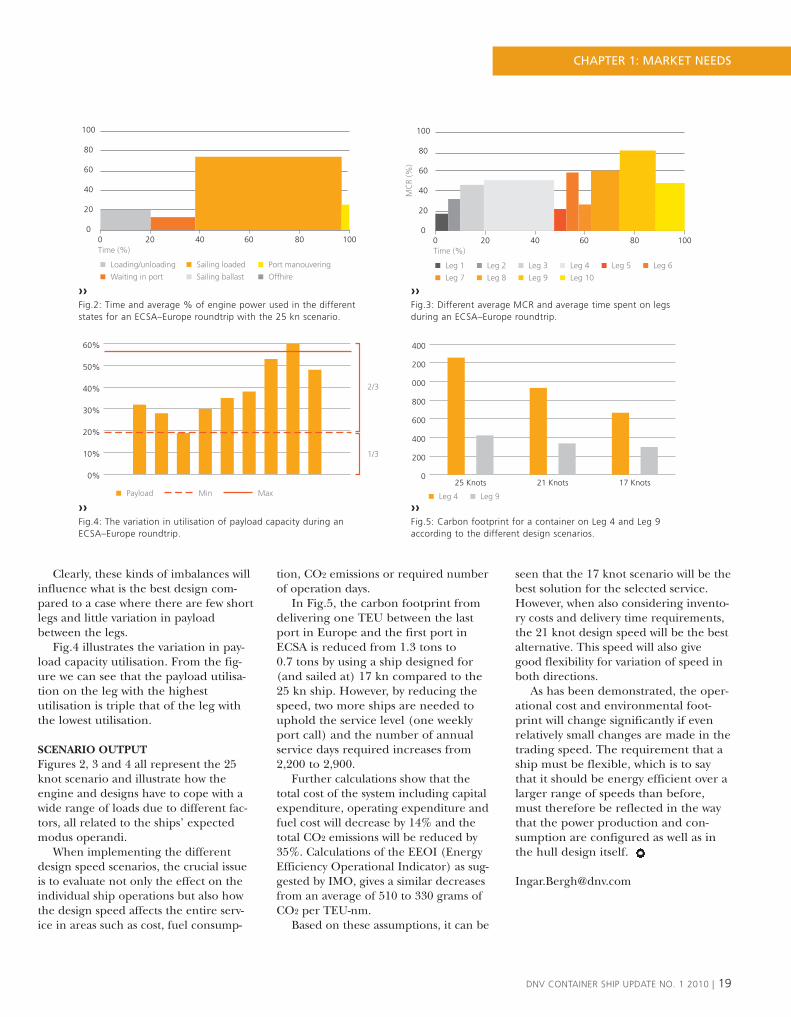
Clearly, these kinds of imbalances willinfluence what is the best design com-pared to a case where there are few shortlegs and little variation in payloadbetween the legs.
Fig.4 illustrates the variation in pay-load capacity utilisation. From the fig-ure we can see that the payload utilisa-tion on the leg with the highestutilisation is triple that of the leg withthe lowest utilisation.
SCENARIO OUTPUTFigures 2, 3 and 4 all represent the 25knot scenario and illustrate how theengine and designs have to cope with awide range of loads due to different fac-tors, all related to the ships’ expectedmodus operandi.
When implementing the differentdesign speed scenarios, the crucial issueis to evaluate not only the effect on theindividual ship operations but also howthe design speed affects the entire serv-ice in areas such as cost, fuel consump-
tion, CO2 emissions or required numberof operation days.
In Fig.5, the carbon footprint fromdelivering one TEU between the lastport in Europe and the first port inECSA is reduced from 1.3 tons to 0.7 tons by using a ship designed for(and sailed at) 17 kn compared to the25 kn ship. How ever, by reducing thespeed, two more ships are needed touphold the service level (one weeklyport call) and the number of annualservice days required increases from2,200 to 2,900.
Further calculations show that thetotal cost of the system including capitalexpenditure, operating expenditure andfuel cost will decrease by 14% and thetotal CO2 emissions will be reduced by35%. Calculations of the EEOI (EnergyEfficiency Operational Indicator) as sug-gested by IMO, gives a similar decreasesfrom an average of 510 to 330 grams ofCO2 per TEU-nm.
Based on these assumptions, it can be
seen that the 17 knot scenario will be thebest solution for the selected service.However, when also considering invento-ry costs and delivery time requirements,the 21 knot design speed will be the bestalternative. This speed will also givegood flexibility for variation of speed inboth directions.
As has been demonstrated, the oper-ational cost and environmental foot-print will change significantly if evenrelatively small changes are made in thetrading speed. The requirement that aship must be flexible, which is to saythat it should be energy efficient over alarger range of speeds than before,must therefore be reflected in the waythat the power production and con-sumption are configured as well as inthe hull design itself.
DNV CONTAINER SHIP UPDATE NO. 1 2010 | 19
Loading/unloading Sailing loaded Port manouvering
Waiting in port Sailing ballast Offhire
0 20 40 60 80 100Time (%)
100
80
60
40
20
0
100
80
60
40
20
0
Leg 1 Leg 2 Leg 3 Leg 4 Leg 5 Leg 6
Leg 7 Leg 8 Leg 9 Leg 10
0 20 40 60 80 100Time (%)
MC
R (%
)
0%
10%
20%
30%
40%
50%
60%
Payload
2/3
1/3
Min Max
››Fig.4: The variation in utilisation of payload capacity during anECSA–Europe roundtrip.
0
200
400
600
800
000
200
400
17 Knots21 Knots25 Knots
Leg 4 Leg 9
››Fig.5: Carbon footprint for a container on Leg 4 and Leg 9according to the different design scenarios.
CHAPTER 1: MARKET NEEDS
››Fig.2: Time and average % of engine power used in the differentstates for an ECSA–Europe roundtrip with the 25 kn scenario.
››Fig.3: Different average MCR and average time spent on legsduring an ECSA–Europe roundtrip.

The conceptual hull designThe Quantum concept design consists of a ‘baby post-Panmax’ of 6,200 TEU with a slender
monohull, low block coefficient and 10% increased container capacity. Alternative hull formswere studied and discarded. The design speed was set at 21 knots based on studies of the
logistics and technical aspects, but the ship can sail at higher or lower speeds. The ship maybe suitable for the Europe to East Coast South America service.
TEXT: ATLE ELLEFSEN
“Design a baby post-Panmax containership for the Europe to South-East Ameri-ca trade, carrying about 5,500 TEU” was the task we were given. To bench-mark our efforts, an existing containership of recent design and similar capaci-ty was chosen as a reference ship.
Our initial brainstorming sessions sug-gested that flexibility regarding speed,draught and cargo composition would
be important in the future. Althoughalmost all current ships of this size aredesigned for a speed of 24–26 knots, theaverage roundtrip speeds may be less.The high speed is necessary in order tomaintain the schedule and catch up pos-sible delays. However, in the presentmarket, the ability to slow steam at 21 oreven 18 knots is an important feature.Lower speeds may also become a perma-
nent feature given future emission legis-lation and fuel prices. We thereforemade the bold decision to reduce thedesign speed to 21 knots. The designspeed determines the hull’s fullness,shape and main dimensions. With alower speed, we needed to find the bestcombination of these parameters.
Naval architects typically turn tomulti-hulls when thinking of ground-
20 | DNV CONTAINER SHIP UPDATE NO. 1 2010
››Fig.1: Final hull, slender and wide with extended topsides.
CHAPTER 2: HULL DESIGN
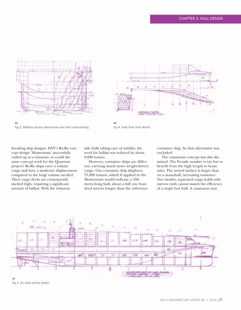
breaking ship designs. DNV’s Ro-Ro con-cept design ‘Momentum’ successfullyended up as a trimaran, so could thesame concept work for the Quantumproject? Ro-Ro ships carry a volumecargo and have a moderate displacementcompared to the huge volume needed.Their cargo decks are consequentlystacked high, requiring a significantamount of ballast. With the trimaran
side hulls taking care of stability, theneed for ballast was reduced by about8,000 tonnes.
However, container ships are differ-ent, carrying much more weight-drivencargo. Our container ship displaces75,000 tonnes, which if applied to theMomentum would indicate a 350-metre-long hull, about a full one hun-dred metres longer than the reference
container ship. So that alternative wasexcluded.
The catamaran concept was also dis-missed. The Froude number is too low tobenefit from the high length to beamratio. The wetted surface is larger thanon a monohull, increasing resistance.Two slender, separated cargo holds withnarrow ends cannot match the efficiencyof a single box hull. A catamaran may
DNV CONTAINER SHIP UPDATE NO. 1 2010 | 21
››Fig.2: An early profile sketch.
››Fig.3: Midship section alternatives and lines materialising.
››Fig.4: Early bow lines sketch.
CHAPTER 2: HULL DESIGN

work for smaller feeder ships carryingdeck cargo only, but for deep sea opera-tion we ultimately concluded that amono-hull was the way ahead.
Of various midship sections, thetrapezoid shape has been a popularalbeit seldom realised idea. The inclinedsides diminish the beam at low draught,thus reducing the wetted surface andresistance. Propeller immersion is main-tained, allowing a high propeller diame-ter. Such a ‘two ships in one’ concept isfeasible for ships trading on an out-bound-homebound type of route with adeep draught on the outbound leg and alighter draught on the homeward one.The market review told us, however, thatthe draught is near constant on our con-tainer run. Thus a straight-sided midshipwas decided upon.
Even today, rough sketches, scribblesand quick hand calculations are typicalof the early design process. A number ofsketches were made of midship sections,lengths, container counts, profiles anddetails. A 5,500 TEU ship with an NPXbeam of 49 metres would, not surprising-ly, be short and full, with a large wettedsurface, a blunt bow, a very shallowdraught, a small propeller, unfavourablecourse-keeping and a high risk of har-monic pitch. Since none of these attrib-utes form part of a naval architect’sdream of a liner, we came up with the‘aircraft carrier’ solution.
The idea of this concept is that morecontainers can be carried above the water-line without increasing the resistance andfuel consumption, since the under-waterpart of the hull is unchanged. After jug-gling with structures, container rows,power curves and stability, the breadth atthe waterline was ultimately optimised at42.5 metres for maximum fuel efficiencyand we decided on 16 containers across atamidships and a novel narrow side tank.Retaining the NPX beam (<49m) topside,the ship’s length ended up at 272,3metres. Leaving our hydrodynamicexperts with free hands to shape the best
possible lines within these constraints, thefinal block coefficient is a very low 0.57,with very low resistance and thus high fuelefficiency. With the wider deck, the designcould still carry 6,200 TEU, 700 morethan the reference ship, thus offeringadded economy of scale.
An important project goal was toreduce or even eliminate the need forballast. This is probably the most bene-ficial measure for future ship designs –due not only to the significant amountof energy required to transport this seawater across the oceans but also to thecosts of treating ballast. Partly achievedby the wide beam but challenged dueto the high cargo stowage topside, thefreedom from ballast is dependent onsophisticated loading procedures. Theneed for ballast water for stability iseliminated for most loading conditions.However, the ship cannot be loadedwith full flexibility in the longitudinaldirection since the trim needs to bekept within limits.
A number of features were added tothe core design, such as an elongated,
raked bow with less flare in order toreduce speed loss in waves and slam-ming. A straight bow in order to max-imise the waterline length was consid-ered but found to be too wet. A largewave breaker is integrated in the foc’slecap in order to deflect the correspon-ding increase in spray and a huge winddeflector is located in front of the fore-most deck container stack in order toreduce wind resistance. Alternative light-weight material may be considered forthese parts of the structure.
The final concept’s innovative factorsare: the wider beam, which increases sta-bility and practically eliminates the needfor ballast; the wide deck enabling thecarriage of more containers withoutincreasing the fuel consumption; a slen-der hull with high fuel efficiency; a bet-ter bow for sea-keeping; the strength-effi-cient narrow double side boxconstruction which saves space; the useof lightweight materials where possible;and the reduced wind resistance.
22 | DNV CONTAINER SHIP UPDATE NO. 1 2010
CHAPTER 2: HULL DESIGN

DNV CONTAINER SHIP UPDATE NO. 1 2010 | 23
››Fig.5: Trimaran suggestion with transverse stowage of outboardcontainers was considered, but not used.
››Fig.6: Trapezoid midship was abandoned due to small draught variations.Note suggested stowage of outboard containers.
››Fig.7: Final bow profile is slender and raked, to soften head seas.
CHAPTER 2: HULL DESIGN

To produce drawings in a pulsatinginnovating team is a challenging task,involving parallel processes like makingdrawings, while container arrangementand hull structure continuouslychanges as a result of design iterations.Frequent project meetings with expertsfrom relevant disciplines like stability,strength, noise & vibration, propulsion,machinery, hydrodynamics and CFD,yard/production, cargo handling andoperation are all parts of the process toarrive at the optimal design. In such aprocess you also need to be pragmaticand not lose sight of the overall goal.
DESIGN ITERATIONS OF SIDE HULLFor illustration, some of the design itera-tions carried out for the side hull isshown in Fig.1.
1. Initial design: This design was devel-oped in a small group with core com-petence on ship design and innova-tion. The initial idea was to design awide double side, to be used for con-tainer stacking.
2. Design Iteration 1: The initial designwas further developed in workshopsand meetings. Challenges and obsta-
cles from the initial design was identi-fied with regards to strength of sidehull and container stacking.
3. Design Iteration 2: A new slender sidehull with passageway outside the mainhull was proposed, with the aim tomaximise the container capacity whileachieving enough space for longitudi-nal piping etc.
4. Design Iteration 3: This iteration wasmostly a back and forth discussion onmany design issues, such as strength,operation, and maintenance.
General arrangement and LNG tank arrangementDeveloping the General Arrangement drawings is a task that requires close interactionwith most of the other disciplines in a concept study. It is also important to have good
knowledge about existing and future rules and regulations which may effect the generalarrangement. For Quantum, the LNG tank arrangement was a particular challenge.
TEXT: HARALD BERGSBAK
24 | DNV CONTAINER SHIP UPDATE NO. 1 2010
››Fig.1: Five stages ofconcept development.
CHAPTER 2: HULL DESIGN

5. Design Iteration 4: The final designwas based on a holistic approach to allprevious iterations, trying to achievethe optimal balance between containercapacity, strength, maintenance, opera-tion, and simplicity of construction.
CONTAINER CAPACITYAn Excel file that represents the GA/Container stacking was developed quiteearly in the project. This file is flexibleand available for all project members;easy to test out different configurations,plan reefer capacity and useful for iden-tifying possible challenges. See Fig.5.
GENERAL ARRANGEMENTThe general arrangement drawing forQuantum is shown in Fig. 2. In Fig. 3 atypical midship section with the newWidedecK™ concept is illustrated. Withthe WidedecK™ solution the deckcapacity increases with two additionalrows. This gives a total container capacityof 6,210 containers of which 3,336 is ondeck and 2,874 is in hold.
LNG TANK ARRANGEMENT The main challenge was to locate andarrange the targeted LNG storage capacityof approximately 5,000 m3 LNG, divided
on two tanks, each of ~2,500 m3. Cylindri-cal, pressurized tanks (IGC tank type C)were chosen, due to their proven technol-ogy. All LNG fuelled ships operating todayuse fuel tanks of this type. They could alsobe made in a double cylindrical shape (Bi-Lobe type) to save space. Prismatic LNGfuel tanks (IGC tank type A, non-pressur-ized) are under development, and may inthe future be used to reduce the spaceneeded for LNG storage.
Cylindrical vertical & horizontal ver-sions of different diameters were inves-tigated, and we decided on two verticaltanks with a diameter of 13m for our
DNV CONTAINER SHIP UPDATE NO. 1 2010 | 25
››Fig.2: Quantum general arrangement drawing.
››Fig.3: Quantum midship section.
››Fig.4: LNG tank section frame.
CHAPTER 2: HULL DESIGN

26 | DNV CONTAINER SHIP UPDATE NO. 1 2010
››Fig.5: Container counting – Excel.
››Fig.7: Machinery arrangement.
CHAPTER 2: HULL DESIGNCHAPTER 2: HULL DESIGN
concept, based on an overall 50/50split on MDO and LNG. See Fig.2 andFig.4.
The LNG tanks will occupy most ofthe traditional engine room spacebelow the accommodation, but thedual-fuel electrical arrangement givesus the flexibility to utilise some of thespace not suitable for containers. Somecontainer slots have to be sacrificed,but this is the case also for pure fuel oilbased ships due to new requirements(MARPOL, regulation I/12A). See Fig.6 and Fig. 7.

DNV CONTAINER SHIP UPDATE NO. 1 2010 | 27
››Fig.8: Hull lines.
››Fig.6: Machinery arrangement.
CHAPTER 2: HULL DESIGN CHAPTER 2: HULL DESIGN

DESIGNED FOR A RANGE OF SPEEDS Slowsteaming has become a hot topic in theshipping business these days and con-tainer ships are right in the middle ofthis discussion. It is not unusual to seeships designed for 24–26 knots operatingat below 20 knots.
The market study presented earlier inthis magazine recommended a designspeed of 21 knots for the Quantum.However, the ship is expected to operateover a wide range of speeds in thefuture.
Modern engines and propulsion systems are designed to be very flexibleand are capable of running at variouspower settings. However, the ship as asystem will operate at a high efficiency
level only if the hull is also designed tooperate at off-design conditions. A hulldesign that is flexible with respect tothe operating speed and displacementswill translate into a reduction in fuelcosts and emissions to air, thus makingthe ship more profitable and greener.
WILL SLENDER HULLS BE THEOPTIMUM APPROACH FOR NEWCONTAINER SHIP DESIGNS?The new Panama Canal dimension givesdesigners more freedom when determin-ing the hull length and breadth; themaximum draft is still restricted by portlimitations.
Several hull parameters need to bescreened in order to optimise the hull
efficiency: length, breadth, block coeffi-cient, longitudinal centre of floatationand bulb shape, among others.
Computational Fluid Dynamic (CFD)tools can be used at an early designphase to optimise the main hull dimen-sions as potential flow computationsallow rapid calculations. The wave pat-terns (see for example Fig.1) and thepressure distributions on the hull can beestimated and used to compare differentpossible design alternatives as well as toevaluate the relative importance of eachresistance component (wave making andviscous resistance).
Once the Quantum’s target displace-ment and design draft had been select-ed, a study was carried out to determine
1.10
1.08
1.06
1.04
1.02
1.00
0,9814 16 18 20 22 24 26 28 30 32
B= 47.5m B= 45.0m B= 42.5m B= 40.0m
Rt
(Rat
io t
o R
t40)
››Fig.2: Hull resistance for different ship breadths shown as a ratio to the40m hull.
Resistance evaluation and hull parametric study
The design speed for the Quantum has been set at 21 knots, quite a lot lower thanthe common speed for modern container ships. The hull needed to be redesigned and CFDsoftware has been used to support the study using various hull parameters. The resulting
ship has a block coefficient which is lower than conventional designs but is wider.
TEXT: GABRIELE MAZZA
28 | DNV CONTAINER SHIP UPDATE NO. 1 2010
1.40
1.30
1.20
1.10
1.00
0.90
0.8014 16 18 20 22 24 26 28 30 32
Cb = 0.63 Cb = 0.60 Cb =0.58
Rt
(Rat
io t
o R
t 0.
57)
CHAPTER 2: HULL DESIGN
››Fig.3: Hull resistance for different block coefficients shown as ratio to the0.57 hull.

the optimum hull block coefficient. Theoptimum block coefficient is closelyrelated to the ship length Froude num-ber. It was found, for a range of speedsaround the design speed, that the bestblock coefficient is 0.57.
A new study was then carried out tofind the optimum combination ofbreadth and length. The breadth of acontainer ship can only be varied insteps driven by the container width.Starting with a beam of 40m, the breadthwas increased to 47.5m in 2.5m incre-ments. The next step would be over themaximum breadth of 49m allowed bythe new Panama Canal.
The effect of the change of breadthand block coefficient on the hull resist-ance is illustrated in Fig.2 and 3. The fig-ure covers a speed range from 16 to 30knots. The resistance is shown as a ratiobetween the hull with the new breadthand the one with a breadth of 40m.
The most efficient hull at the designspeed of 21 knots is the one with abreadth of 42.5m; the waterline lengthwould consequently be about 260m. Thishull is also the one least penalised foroff-design conditions over the entirespeed range.
POWER ESTIMATIONAND TRIM CHECK A preliminary estimate of the powerrequired for the engine and propulsionselected was carried out using CFD simu-lations based on the final hull parame-ters. For the final power estimation, tow-ing tank model tests should be carriedout to complement the numerical simu-lations.
Container ships operate at multipletrim and draft conditions because of the
type of cargo they carry. It is possiblethat a large trim by the stern (transomimmersion) or by the bow (loss of effec-tiveness of the bulb) may influence thehull efficiency. Fig.3 shows that for thisspecific hull at the design draft of 12mand design speed, the influence of trimis marginal.
››Fig.1: Wave patterns for two different hull designs.
100.2%
0.0 0.2 0.4 0.6 0.8 1.0 1.2 1.4 1.6 1.8
Rt
(Rat
io t
o e
ven
kee
l)
99.0%
100.0%
99.8%
99.6%
99.4%
99.2%
2.0
Rt (Ratio to even keel)››Fig.4: Trim effect on the hull resistance of the design draft at the design speed.
DNV CONTAINER SHIP UPDATE NO. 1 2010 | 29
CHAPTER 2: HULL DESIGN

Added resistance in seaways – optimising the hull for seagoing conditions
Due to a lack of adequate computational tools, ship hulls have traditionally been designed foroptimal performance in calm waters. In seaways, ships will be exposed to additional forces resultingin motions and added resistance. The seakeeping computer program DNV-Wasim has been extended
to calculate the added resistance when taking such effects into account. By using this tool in thedesign phase, the hull can be optimised for more realistic conditions.
TEXT: JENS BLOCH HELMERS
DNV-Wasim was applied in order toinvestigate the effect of trim on addedresistance for the Quantum design. Thelevel of added resistance depends on thehull shape, loading condition and howthe ship is operated in the actual seastate. When added resistance is at itsmaximum, a dominant contribution isrelated to the concurrent distribution ofrelative wave elevation along the hull.The change of wetted area has implica-tions for several physical effects thatshould be taken into consideration.
It is quite common for an optimaldesign with respect to calm water resist-
ance to have a detrimental effect onadded resistance and vice-versa. Forinstance, some optimised bulbous bowsmay increase the added resistance in cer-tain wave conditions. Another example isthe effects of a slender hull, which mayhave excellent calm water resistance butpotential increased pitch motion –hence increased added resistance.
A good design should take both calmwater and seaway operations intoaccount. DNV-Wasim is now an impor-tant tool in that respect, in addition toother advanced seakeeping assessments.As well as assessing the ship’s added
resistance characteristics, the new post-processor WaqumExplorer can assist ininvestigations into optimal routing andcourse keeping.
It is well known that draft and trimmay have a significant influence on thecalm water resistance of ships, and variouscalculation programs and empirical dataexist for such assessments. However thecorresponding effects in seaways havebeen a difficult research topic for yearsand no commercial tools are available.
30 | DNV CONTAINER SHIP UPDATE NO. 1 2010
››The Wasim simulation carried out for Quantum at resonant ship motions reveals the hull’s added resistance in waves.
CHAPTER 2: HULL DESIGN

DNV CONTAINER SHIP UPDATE NO. 1 2010 | 31
››Boxes in boxes lifting arrangement.
››Midship section.
CHAPTER 2: HULL DESIGN

››The model of the Quantum concept is on display at the DNV headquarter reception.


34 | DNV CONTAINER SHIP UPDATE NO. 1 2010
SANDWICH STRUCTUREA structural sandwich is a special form of a laminated composite comprising of acombination of different materials that are bonded to each other so as to utilisethe properties of each separate component to the structural advantage of thewhole assembly.
COMPOSITE SANDWICH STRUCTURE
TYPICAL MATERIALS
Face Materials:• Fibre-reinforced plastics laminates, e.g. glass fibre and epoxy resin• Metal sheet
Core Materials:• Foam• Balsa wood• Elastomer• Honeycomb
KEY PROPERTIES• High stiffness to weight ratio• High strength to weight ratio• Good fatigue and corrosion properties
DESIGNER FLEXIBILITY• Properties can be tailored• High margin against catastrophic failure• Dampening of noise and vibration• Improved thermal insulation
Lightweight composite structures have awide and compelling track record inweight-critical marine applications, suchas high speed light crafts. They offeropportunities for not only major weightreduction but also reduced mainte-nance costs due to better corrosion andfatigue properties. The results of R&Dprojects have demonstrated that weightsavings of 30–70% can be achieved withlightweight composites compared to tra-ditional steel structures.
Until recently, the SOLAS regulationsrequired load-bearing structures to be
made of non-combustible materials.However, a recent amendment to theseregulations now allows the use of com-posite materials provided that adequatesafety is demonstrated by a risk assess-ment and a fire engineering analysis.
WEIGHT SAVING IN QUANTUM For Quantum, a study was first carriedout to screen the potential applicationareas in order to estimate the weightreduction potential and acquisition costand identify the most promising solu-tions. The focus was then put on the
superstructure, piping and hatch coversbased on feasibility and potential. Theresults of the study showed that, by usinga glass fibre reinforced plastic (GFRP)composite sandwich construction, a sig-nificant weight reduction in the range oftonnes 1,100 can be achieved by onlyfocusing on these items.
The use of 1,200 FEU reefers isanother area with opportunities, whereincreased volume capacity, weight sav-ing and a reduction in the power usedby cooling units can be achieved. Foamcore sandwich structures offer the addi-
Lightweight structuresSteel is a strong and durable material. However, lightweight structures offer
a range of opportunities to build a green, efficient, profitable and reliable containership at a competitive price. For Quantum, weight savings of 1,100 tonnes have
been achieved by using composite structures.TEXT: PHILIPPE NOURY AND KRISTOFFER BRINCHMANN
CHAPTER 2: HULL DESIGN

DNV CONTAINER SHIP UPDATE NO. 1 2010 | 35
tional benefits of an integrated insulat-ing function in addition to stiffness andan improved strength to weight ratio.The weight saving potential is estimatedto be about 2,000 tonnes compared to atraditional steel design for 1,200 TEUreefers.
Weight reduction could be directlyturned into financial benefits in twodifferent ways: to reduce fuel con-sumption and CO2 emissions and/orto increase the service speed and oper-ation range. The reduction in fuelconsumption was estimated to be inthe order of 1–3.5% based on weightsavings of 2,000–5,000 tonnes.
OTHER BENEFITS FRP materials aresubject to little or no corrosion if usedproperly. Such materials are virtuallymaintenance-free, producing low run-ning costs. Stress concentrations are lesscritical than with metals, hence fatiguecracking is less of a problem. For
instance, it is estimated that the fatiguelife of composite piping in seawater is20 years compared to seven for steelpiping.
Two of Quantum’s special featuresare the large wind deflector and wavebreaker located in the fore. Both com-ponents are to be built in GFRPbecause of this material’s low weightand superior corrosion resistance andthe ease with which it can be formedinto complex shapes.
COSTS The cost of materials for a lightweightstructure is higher than for an equiva-lent steel structure. However, buildinglarge quantities for large structures pro-duces lower prices. Studies of FRPmarine structures show that the totalcost (materials, fabrication, finishingand installation) varies from about 0.6to 2 times the cost of an equivalent steelstructure. The operating cost is
assumed to be lower than that of a tra-ditional steel structure. Hence, a smallinitial investment of a few per cent ofthe construction costs may yield signifi-cant lifecycle savings. Whether or not alightweight construction is commercial-ly attractive depends largely on theintended trade and how those new ben-efits are capitalised on.
RECYCLING The recycling of composite materials isbecoming an important topic as thevolume of composite used in the worldis growing fast. No universal solutionfor recycling composite materials hasyet been found. Nevertheless, thereare a number of promising technolo-gies that have been and are being test-ed with two kinds of valorisation: ther-mal and material.
[email protected]@dnv.com
››Wind deflectorand wave breakerbuild in GFRP.
CHAPTER 2: HULL DESIGN

Hull strength –more boxes into the box ship?
The double bottom and double side are normally designed asballast tanks. Very often, there is more ballast capacity than is
necessary. Can some of these spaces be used to stow containers? In the Quantum project, two alternatives were investigated from a strength and scantlings point of view. The final design has a
narrow double side, designed as a void space.TEXT: HE JIANG
36 | DNV CONTAINER SHIP UPDATE NO. 1 2010
››Fig.3: FEA – cargo hold model.
CHAPTER 2: HULL DESIGN

Two different concepts for the Quan-tum were evaluated to maximise thecontainer capacity and reduce the shiplightweight as much as possible:� Decreasing the traditional double
side (See Cross Section A – Fig.1)� Container stowage in the double
side (See Cross Section B – Fig.2)
By making the traditional double sidenarrower, the container capacity canbe increased. The double side com-partments are very narrow and aredesigned as void spaces. The doubleside just below the strength deck andthe top wing space further below maybe utilised as an access tunnel andpipe duct.
The double side void space isapproximately 1m wide with a uni-gird-er system. This means that all the lon-gitudinals are replaced by longitudinalstringers which are supported by trans-verse structures instead of transversebulkheads alone, leading to a span ofmore than 12m.
The first advantage is that the totalarea of Cross Section A is less thanthat of Cross Section B, which meansless steel weight. Also, the introductionof the uni-girder system will eliminateall side longitudinals around thedraught and consequently eliminaterelevant fatigue cracks where side lon-gitudinals connect to the web frames.Therefore, survey and maintenancework will not require a lot of access tothe narrow void space.
The access to the double side spacewill be rather difficult. However thedouble side space is designed as a voidspace only, so that the corrosion in thespace will be quite limited comparedto that in the ballast tanks.
As can be seen in Fig.2 (Cross Sec-tion B), it was decided to utilise thedouble side compartments for contain-er stowage. The arrangement makesthe double side wider so that contain-ers can be stowed in it. One row ofcontainers is stowed in the lower part
of the wider compartment. In theupper part, there is enough space tostow two rows of containers. The nar-row double side just below thestrength deck and the top wing spacefurther below may be utilised as anaccess tunnel and pipe duct.
From a strength point of view, thechallenge was to design sufficient lon-gitudinals for the outer and innershell. If a 40-foot container was to bestowed in the wider double side, thespan would be more than 12m, result-ing in too large sizes for the longitudi-nals. However, the wider double sidecould be designed for 20-foot contain-ers only, making it is possible to con-trol the size of longitudinals, cellguides and relevant clearance.
Another challenge was the torsionstiffness of the hull girder. Because thestrength deck between the inner sideand outer side has been removed inCross Section B, it will be an open typestructure and the hull girder torsionstiffness will be reduced.
Following an evaluation of theadvantages and disadvantages of theCross Section A and B designs, theformer was chosen for Quantum. Afinite element analysis for a ½+1+½cargo hold model has been conduct-ed for this design (see Fig.3). In gen-eral, the analysis shows that thearrangement is sufficient with respectto strength. However, there are somespecial areas where careful considera-tion is necessary. The stress level forstringers in the narrow double sidevoid space is in general low. However,because all the stringers are connect-ed to transverse structures instead oftransverse bulkheads alone, specialattention needs to be paid to the webplates and connections with the trans-verse bulkheads. Considering thatopenings on these vertical webs arenecessary to enable access to thespace, the buckling capacity of verti-cal web panels should also be careful-ly considered.
In the end, the concept came outwith approximately the same steelweight as a 5,500 TEU comparisonship, even though the containercapacity has been increased byapproximately 10%.
DNV CONTAINER SHIP UPDATE NO. 1 2010 | 37
››Fig.2: Cross Section B – Wider Double Side.
››Fig.1: Cross Section A – Narrower Double Side.
CHAPTER 2: HULL DESIGN

DAMAGE STABILITY Generally speaking,the damage stability requirements aremore critical than the intact stabilityrequirements. Also, as a result of newharmonised probabilistic damage stabili-ty rules which took effect on 1 January2009, discussions about what effects thenew rules will have on ship designs havebeen held throughout the shippingindustry. Therefore, while designingQuantum, the focus has been on certaindesign factors which will influence con-tainer ships’ damage stability results.
The new probabilistic damage stabilityrules can be summarised in the veryshort formula A ≥ R where A is theattained index and R is the requiredindex.
For Quantum, the maximum damageextent taken into consideration is up to
three compartments, and over 600 dam-age cases have been defined and calcu-lated. A typical damage case is illustratedin Fig.1.
As a major design factor, the size ofthe double shell (a typical cross-sectioncan be seen in Fig.2) will have a certaininfluence on the cargo hold capacity,and it may also be of great interest toinvestigate the probabilistic damage sta-bility results for different widths of thewing tank.
Two different sizes of double shell(Design A and Design B) in cargo holdsNo.5 and No.4 have been studied. AsNo.5 and No.4 are located in the middlepart of the ship, this will give a clearindication of the damage stability results.Some design factors are summarised inTable 1.
When calculating the attained indexA, each partial index is a summation ofthe contributions from all the damagecases taken into consideration, using thefollowing formula:
Here comes the probabilistic concept.is the probability that only the com-
partment or group of compartmentsunder consideration will be flooded; and
is the probability of surviving certaindamage.
The probability of certain damagehappening to a single compartment or agroup of compartments, , is highlydependent on the geometric arrange-ment of the considered ship. For exam-ple: for the damage case shown in Fig.2which penetrates all the way to cargoholds No.4 and No.5, = 0.04215 forDesign A and = 0.04468 for Design B.
How about then? The overall sta-bility of the ship will be improved evenwhen the possibility of a serious dam-age case happening is increased (seeTable 1 for volume information for thecargo hold and side shell space). ForQuantum, both designs achieved = 1,which means that, for Design B,although the chance of having thecargo hold damaged is 3% higher thanwith Design A, this damage case con-tributes more in the summation .One conclusion that can be reached isthat as long as the ship can survive the
Minimum ballast design – intactstability and damage stability
The handling of ballast water creates a lot of extra operational challenges which areexpected to increase in the future due to the introduction of a requirement of aBallast Water Treatment System. In addition, by removing the ballast water, morecargo could be carried with the same displacement. As a result, while designingQuantum, how to achieve a ballast-free green ship and at the same time fully
comply with all the stability rules has been a major concern.TEXT: YANG ZHANG
38 | DNV CONTAINER SHIP UPDATE NO. 1 2010
Volume (m3) Design A: Size of Design B: Size of
widest part of side widest part of sideshell d =1.73m shell d =1.25m
Cargo Hold No. 5 25,915.5 26,729.5Void Space No. 5 (S-side) between double side shell and hull 1,331.1 930.8Double bottom ballast tank No.5 (S-side) 1,102.1 1,122.7Cargo Hold No. 4 26,221.8 27,077.9Void Space No. 4 (S-side) between double side shell and hull 1,172.0 747.6Double bottom ballast tank No. 4 (S-side) 1,298.4 1,308.3
Table 1 Cargo hold capacity of No. 5 and No. 4
CHAPTER 2: HULL DESIGN

damage (i.e. = 1), the side shell sizecan be even less in order to achieve ahigher cargo capacity.
The above analysis is only based onone damage case shown in Fig.2.
The final results of Designs A and Bare shown in Table 2.
LOADABILITY – INTACT STABILITY As mentioned in the first paragraph, thedamage stability is normally more criti-cal. In order to comply with probabilisticdamage stability, the GM value has to bekept at least at 1.25m.
Bearing this in mind, some loadingconditions have been tested with respectto the intact stability. From the results, it has been found that stability is not acritical issue for most of the realistic con-
ditions, and ballast water is hence notneeded for the purpose of stability. How-ever, the trim is an issue for some of theconditions, depending on the weight dis-tribution of the containers.
Thus, there are two design and oper-ation options when it comes to ballastwater:� Using an intelligent loading system,
the trim and bending moment can becontrolled by distributing the weightproperly in the longitudinal direction.In this case, ballast water is not need-ed, which means that fuel can be savedand ballast water treatment can beavoided. This should be the option forthe future.
� If flexible loading is a requirement, bal-last water can be used to achieve thecorrect trim regardless of the containerweight distribution. The ballast watercan then also be used to control thebending moment. This is normal prac-tice in container ships today.
DNV CONTAINER SHIP UPDATE NO. 1 2010 | 39
Z=18
PROFILE››Fig.1: Two-compartment damage case with damage penetrating into cargo holds No.5 and No.4.
››Fig.2: Typical cross section.
Required Subdivision Index R Attained Subdivision Index ADesign A GM =1.25m 0.6967 0.70852>RDesign B GM =1.25m 0.6967 0.71720>R
Table 2 Final results
CHAPTER 2: HULL DESIGN

Machinery and ship systems– a flexible solution for an uncertain future
Recent change in the global economy and increased worldwide environmental concerns haveopened up for new machinery concepts as realistic alternatives to traditional designs. For
Quantum, an arrangement with electric propulsion powered by four dual-fuel generator setswas chosen. The main advantage with electric propulsion is the flexibility to operate more
efficient across a wide range of speeds. By switching to LNG when approaching the coastline,ECA requirements are fulfilled and cold ironing is not needed. Two azimuth pods ensure
excellent manoeuvrability and increased harbour efficiency.TEXT: ERIK BRODIN
OPERATIONAL FLEXIBILITY Container ships are known for utilisingthe largest engines available, justifiedby one single reason – the need forspeed. However, in today’s uncertainmarket, more variations in operationalspeed are seen. A large portion of thecontainer fleet is now slow steaming,with engine loads down as low as to10% MCR. Although the ships arereducing their total fuel bill by slowsteaming, the specific fuel consump-
tion is increasing. This is because theseengines often have their maximumfuel efficiency at around 80-85% MCR,while the amount of fuel needed perkW is larger at lower loads.
With a conventional design, largevariations in power consumption canlead to operational challenges. Longperiods of low engine load operationwill result in problems with soot forma-tion due to a lower compression tem-perature and reduced exhaust gas
velocity. As a result, a “blow out” withhigh engine loads at regular intervalsmay be needed. In addition to beingan operational disturbance, this willalso result in unnecessary increasedfuel consumption compared to contin-uous RPM sailing. This opens up fordiesel electric transmission, where thepower management system will ensurea balance between the consumed andavailable power. Diesel electric systemsare much better than traditional
40 | DNV CONTAINER SHIP UPDATE NO. 1 2010
CHAPTER 3: MACHINERY AND SYSTEMS
››Fig. 1 Quantum machineryarrangement

mechanical systems with respect tooperational flexibility, engine locationand the utilisation of space.
QUANTUM’S MACHINERY SYSTEMSThe chosen concept has electricpropulsion powered by four dual-fuelgenerator sets fuelled by MDO andLNG, providing flexible and environ-mental friendly operations. See Fig. 1and Fig. 2. If the ship needs to operateat a lower speed, one engine may beshut down, leading to optimised opera-tion and fuel consumption for theremaining three engines that still arerunning.
Do tomorrow’s container ships needa service speed as high as 25 knots orcould it be less? With the strong focuson the carbon footprint, this issue willhave to be thoroughly evaluated, sinceall other environmental initiatives areof less importance than the operatingspeed. It is estimated that Quantumwould need nearly 50 MW of propul-sion power for a service speed of 25knots, while less than 24 MW is enoughfor 21 knots, including the sea margin.To have some flexibility, a maximumpropulsion power of 30 MW has beendefined for Quantum, which gives a
maximum service speed of 22.5 knots.This includes an 18% sea margin, 4%air resistance, 5% appendices resist-ance and 70% propeller efficiency.
Quantum has 1,200 reefer plugsand each reefer container can requireup to 12 kW at full load. The need forpower to the reefers depends on theoperating profile, such as the numberand type of reefers loaded in eachport. Different kinds of cargos havediffering temperature and ventilationrequirements. There may also be largeseasonal variations for products likefruit and Christmas trees. Hence thepower consumption can be anythingbetween 0 and 14 MW.
Quantum has 33 MW of installedengine power, allowing it to keep tothe 21 knot design speed with all possi-ble service loads.
CHOICE OF FUEL IS A KEY TOPICHFO has been more or less the onlyoption for seagoing ships. However,the stricter emission regulations underthe IMO Tier II & III and ECA zoneimplementations and volatile fuelprices mean that ship owners andoperators are facing serious chal-lenges. Solutions that allow compli-
ance with new environmental ruleswhile maintaining cost-efficient opera-tions vary, but LNG appears to fulfil allthe requirements. LNG is not only anenvironmentally good solution, it isalso economically interesting when theexpected increase in the fuel oil priceand future costs related to emissionsare taken into account. Furthermore,there will be no need for additionaland possibly very expensive solutionslike scrubbers, cold ironing andhumidification.
As a result, a dual-fuel concept wasselected for Quantum. Fuel flexibilityenables owners and operators to opt forthe most suitable fuel, taking account oflocal environmental restrictions, fuelprice variations and fuel bunkeringavailability. Fuel flexibility also repre-sents a significant safety feature. In thecase of an interruption to the gas sup-ply, duel-fuel engines automaticallyswitch to diesel operation without anyloss in speed or power output. Single-fuel installations do not have this addi-tional level of operational safety. With adual-fuel solution, the complex settlingand mixing tank arrangement used forthe fuel switch between HFO and MGOis also avoided.
DNV CONTAINER SHIP UPDATE NO. 1 2010 | 41
CHAPTER 3: MACHINERY AND SYSTEMS
››Fig.2 Quantum machinery arrangement with two Azipods

PROPULSION ARRANGEMENTElectric propulsion opens up formany different arrangements. Sever-al concepts have been evaluated aspart of this study and some of themare presented in Fig.3.
FIXED PITCH SINGLE SCREWSOLUTIONSA fixed pitch single screw has upto now been the preferred solu-tion due to its simplicity and highefficiency. Fixed pitch implies thatpower and torque are controlledby the propeller speed, given by acharacteristic propeller curve.The traditional concept is to haveone direct coupled two-strokeengine, which has no systemredundancy. Two engines mayprovide increased redundancy,but a major part of the increased
availability is lost by introducing areduction gear without redundan-cy. With two engines and one pro-peller, it is possible to operate onone engine during slow steaming,but the fact that the gear is ahigh-cost component makes thegain questionable.
It is possible to combine singlescrew and electric propulsion, buta single electric motor of this sizeis not common and will be bothexpensive and heavy. Another solu-tion is to use a gear driven by twoelectric motors (not shown inFig.3). It is a matter of costs whichsolution to choose. The power lossbetween the engine and propellerwith electric transmission is 8-9%,mainly in the generator and motor,while a direct coupled two-strokeengine has negligible losses.
A reduction gear will also intro-duce some losses; approx 1-2%.The flexible electric power produc-tion can be utilised by usingPTI/PTO for a direct coupled fixpitch system. The generator haslarge inertia, making it preferableto have it shaft mounted instead ofgear mounted when running inrough sea. The generator has tofollow the engine speed, which isvariable and less than 120 rpm, soa frequency correction is requiredor a DC-generator can be used.Manoeuvrability was defined asimportant for this project due tothe considered trade and route, soeven with large stern thrusters asingle screw is not the first choice.A large fixed pitch propeller mayalso perform worse in shallowwaters due to vessel squatting.
42 | DNV CONTAINER SHIP UPDATE NO. 1 2010
CHAPTER 3: MACHINERY AND SYSTEMS
1 Single screw: a) direct driven, b) geared transmission, c) electric driven
2 Twin screw: d) direct driven, e) geared transmission, f) electric driven
3 Azimuth thruster: g) Electric pods and shaft propeller
1
2
3
a) b) c)
d)
g)
e) f)
››Fig.3 Different arrangements suggested.

TWIN SCREW SOLUTIONSWith a twin screw arrangement, it ispossible to have full redundancyand increased manoeuvrability. Thepower efficiency is not clear sincethere are increased losses from thetwin-skeg and reduced losses relat-ing to wave resistance and the pro-peller. The twin screw conceptopens up for a hull with a reduceddraught since the propeller diame-ter is smaller. One drawback with atwin-skeg solution is the mountingof aft tunnel thrusters, since itrequires a longer tunnel.
ROTATING PODS See Fig. 4. As a means to increasemanoeuvrability and operationalflexibility, azimuth thrusters wereevaluated. The first to be consid-ered were two rotating pods + one
electrically driven fixed pitch pro-peller used to boost the power intransit mode. In manoeuvre mode,only the pods are in operation.This was found to be a very costlysolution, which is relevant for high-er speeds and power only. Differ-ent concepts with three pods werealso rejected for the same reason.
QUANTUM ARRANGEMENTThe arrangement chosen forQuantum is a concept with tworotating pods as presented in Fig.2. The main advantage of pods isthe excellent manoeuvrability theyallow. With pods there is also noneed for stern thrusters and rud-ders. Quantum will call at 10 portsin a round trip voyage, 45% ofwhich will be in coastal waters.Good manoeuvrability increases
the efficiency in harbour andreduces the need for tugs. The esti-mated savings on tug assistance arein the range of Euro 400 000 peryear, taking account of the fact thatsome ports have mandatory tugassistance. The main disadvantageswith a pod solution are the higherinvestment costs, increased propul-sion power transmission losses andthe need for qualified electricianson board.
The major manufacturers oflarge pods (6-25MW) are ABB (Azi-pod) and Rolls-Royce/Alstom(Mermaid). The required propul-sion power of 23MW could be pro-vided, for instance, by two ABBVO1800 or XO2100. There havebeen uncertainties regarding thehydrodynamic loads acting on thepods, but ABB and DNV have car-
DNV CONTAINER SHIP UPDATE NO. 1 2010 | 43
CHAPTER 3: MACHINERY AND SYSTEMS
››Fig.4: ABB Azipods are at the moment the most common electrical pod unit.This illustration is of a larger unit than the one used in this concept.

44 | DNV CONTAINER SHIP UPDATE NO. 1 2010
CHAPTER 3: MACHINERY AND SYSTEMS
ried out continuous full-scalemeasurements of a pod inservice over a period of twoyears in order to determinethese. Pods are also a rela-tively new concept comparedto direct driven or gearedmechanical systems; hencethere have been some qualitycases which are well knownin the maritime business,leading to some septicism.However, new design genera-tions have now been present-ed and the initial problemsare assumed to be solved.
DUAL-FUEL ENGINESSee Fig.5. Today there are twomakers of large four-stroke dual-fuelengines: Wärtsilä (50DF) and MAN(51/60DF). Both engines have a rating ofapprox 950-1000 kW/cyl, which we expectto increase to 1100-1200 kW/cyl withinfive years. These are four-stroke medium-speed engines which are well suited forgenerator application and operate atapprox 500 rpm depending on the electri-cal frequency.
When fuelled with MDO or MGOthey run as a diesel engine, following thethermal Diesel-cycle. They also have agas mode with an independent fuel sys-tem that operates using LNG. Thisprocess follows the Otto-cycle, and asmall pilot injection with, e.g., MGObehaves like a spark plug. It should benoted that MAN has a two-stroke dual-fuel engine (ME-GI), but for this applica-tion both rpm and weight are advantages
held by the four-stroke engines. In order to achieve full redundancy,
the vessel will have two engine rooms –PS and SB. In general, a V-engine will beshorter than an L-engine but the over-haul time is longer and maintainability isreduced due to the cylinder angle. It ispreferable to have at least one smallengine which can be operated at lowload in port when there is no reeferload. Based on this, a setup with L6 +3xL9 has been chosen.
Even though a pod solution has beenselected for the Quantum concept, it isimportant to remember that the selecteddual-fuel engines with LNG can also beused in a conventional propulsionarrangement with a single screw as
shown in Fig.3. The bene-fits of complying with theemission regulations inECA areas would still bethere, and the need forother additional measureswould be eliminated.
ECONOMYThe additional invest-ments in the machineryand propulsion systemhave to be covered byreductions in fuel cost,manoeuvring time, emis-sion taxes and tug assis-tance.
ABB has carried out alife cycle cost analysis of
two alternative propulsion systems basedon the operational profile defined forthe Quantum project. The disadvantageof mechanical transmission is related tounexpected downtime (533 k€/year),failure-related maintenance and lube oilconsumption. The main results for thechosen concept compared with a tradi-tional concept are presented in Fig. 6. Itcan be seen that the cumulative costs ofthe Quantum design are approx. 11%higher than those of a conventionalarrangement. A concept study like thiscontains many uncertain parameters butit provides an indication of the cost-pic-ture for the machinery and propulsionarrangement.
Configuration Investment Maintenance Fuel Cumulative costM€* k€/year* tons/year* M€ after 30 years*
2 x 15 MW pods, 40 MW DF gensets 29,2 1.067 25,208 212Direct mechanical propulsion, 11,9 1.268 23,357 187one 2-stroke engine, one 12MW genset, Thrusters and rudder
* Analysis is based on 30MW propulsion power and HFO as fuel. Engines, electric equipment are included, but not hull investments.
››Fig.6 Output from life cycle cost analysis
››Fig.5 MAN 51/60 DF is an example of a dual-fuelengine

DNV CONTAINER SHIP UPDATE NO. 1 2010 | 45
Introducing LNG into the fuel mix
For many decades, Heavy Fuel Oil (HFO) has been the predominant alternative for marine fuel.Today, the situation is more open and several options have to be considered. The revised Annex
VI of MARPOL 73/78 adopted by the International Maritime Organisation (IMO) in 2008introduces stricter requirements for NOx, SOx and PM emissions and local emission-controlled
areas (ECAs) define even stricter emission requirements. Several oil fields are now depleted anda lot of the remaining oil is in areas where there are political conflicts, so the future crude cost
is uncertain. LNG could be part of the solution for the future. TEXT: ERIK BRODIN
QUANTUM FUEL MIX The choice of a fuel for the Quantumconcept was based on some assumptionsand choices: � Electric propulsion� Increased prices for LSHFO due to
lack of LS crude� New areas with emission restrictions
(ECAs) will be established, e.g. 200 nmfrom all coasts
� The availability of LNG will be estab-lished when there is a market
A dual fuel solution was chosen, withMDO for Atlantic crossings and LNG forthe coastal legs and LNG refuelling inEurope and South America. A pure LNGsolution was not realistic since LNGrequires more space for tanks and gashandling, which is lost cargo space.
WHAT ARE THE ALTERNATIVES More or less all merchant ships today usefossil fuel as their energy source. Up tonow, heavy fuel oil (HFO) has been themost common fuel for sea going ships.This fuel consists of heavy products and iswhat is left of the crude (residuals) afterlighter products have been removed dur-ing the refinery process. It has a largevariety of properties with respect to viscos-ity, flash point and amount of contamina-tions, such as sulphur. The use of low sul-phur heavy fuel oil (LSHFO), which
means less than 0.1% sulphur in 2015, isone option to reduce this emission, butremoving the sulphur increases the fuelprice. In the table below, the difference isonly 20 $/ton, probably because both maybe based on an LS crude, but the differ-ence will increase when the demand forLS fuel increases. It is not easy to comparefuels since the prices vary so much, e.g.IFO380 was down at 210 $/ton one yearago. It should be noted that IFO is ablend of HFO and a small amount ofMGO. The density of HFO is approxi-mately 1,0 kg/m3, so water separation canbe a challenge.
Fuel $/tonHFO (IFO380) 430LSHFO (LS380) 450MGO 605MDO 570LNG 450
Fuel cost in Europe (approx. Dec 09) Sources: Bunkerworld, IEA OMR etc.
Marine gas oil (MGO) and marine dieseloil (MDO) are refined from crude andare so called distillates. The main disad-vantage of residuals compared with distil-lates is the need for heating before use orpumping, which normally requires asteam system. Maintenance and operationare also easier when HFO can be avoided.
HYDROCARBON AS FUELAvailable energy is obtained as heat fromcombustion in which hydrocarbons and oxygenhave a chemical reaction. The reaction equationfor alkanes, which are the simplest ones, whenthere is enough oxygen, is:CnH2n+2 + (1.5n+0.5)O2 –––> (n+1)H2O +nCO2
In addition to energy, water (H2O) and carbondioxide (CO2) will always be an end-product.The ratio of energy to CO2 depends on thehydrocarbon that is reacting. Each carbon atomhas four bounds and for methane (CH4) allbounds are occupied by a hydrogen atom. Thehigh hydrogen to carbon ratio is one reasonwhy methane produces less CO2 per energyunit. The lack of oxygen (O2) will lead to theproduction of carbon monoxide (CO) or carbon(C) as soot particles.
The NOx products are formed by combustionunder high temperature. Nitrogen comes fromboth air and fuel. In general, high efficiencydepends on high temperature, hence a decreasein NOx will lead to an increase in CO2. Ingeneral, the NOx emissions depend on theengine design. NOx can be extremely toxic andis also a greenhouse gas.The SOx products are created duringcombustion but are only dependent on thefuel’s sulphur content. SOx is a major cause ofacid rain.
CHAPTER 3: MACHINERY AND SYSTEMS

46 | DNV CONTAINER SHIP UPDATE NO. 1 2010
CHAPTER 3: MACHINERY AND SYSTEMS
At the moment, the price of MDO is26% higher than LSHFO. This has to bebalanced by other benefits.
LNG FOR THE FUTURELNG is different since it is based on nat-ural gas and not on crude. LNG containsno sulphur and emits 90% less NOx andwill almost eliminate particulate emis-sions.
CO2 can be reduced by approx. 25%(but with an increase in methane this fig-ure is reduced to approx. 15%).
LNG’s properties were presented inthe last edition of DNV Container ShipUpdate in relation to short sea shipping,but a brief description will be given hereas well. LNG is a blend of gases whichmay vary but is dominated by methane.
Formula Name content %N2 Nitrogen 0.3–2 CH4 Methane 87–98C2H6 Ethane 2–8C3H8 Propane 0.2–3
Blends of nitrogen and alkanes in LNG
The properties are more or less as formethane, which has a boiling point of–161.6°C.
MDO LNG % rel. MDODensity 880 450 49Energy MJ/kg 44 50 –14Energy TJ/m3 39 22 44Comparison between LNG and MDO, approx.values. Energy is based on low heating value(LHV).
The values above are not exact sinceboth are blends. LNG needs approxi-mately. 40% more volume for the sameamount of energy, but it should be notedthat there will always be some carryoverin the LNG tanks. The tank itself mustalso be larger due to pressure, insulationand gas handling equipment. Hence,LNG may require up to three times asmuch space as MDO.
LNG was traditionally used as fuel inLNG tankers due to the boil-off from thecargo tanks. Today, several coastal shipslike ferries and offshore ships use LNGas ordinary fuel in dual fuel (MAN andWärtsilä) or pure lean burn gas engines(Rolls-Royce and Mitsubishi). Dual fuelengines can operate on HFO, but MDOis required as pilot fuel when operating
BRIEF STATUS OF EMISSION REQUIREMENTS
The revised MARPOL Annex VI Regulations for the prevention of air pollutionfrom ships, which enters into force on 1 July 2010, sets the new limits forpermissible NOx, SOx and particulate emissions to air.
Nitrogen oxide (NOx) emissions have three tiers. Tier I is for ships constructedin 2000 and later, and was ratified by flag states representing more than 50%of the merchant fleet tonnage. Tier II is stricter and is a global requirement asfrom July 2011. Tier III will be even stricter, but is limited to emission controlledareas (ECAs) like the Baltic Sea, the North Sea and most of the US & Canadiancoast. Tier III will come into force in 2016. The NOx limits are for enginesabove 130 kW and depend on rotational speed.
The sulphur oxide (SOx) requirements state the maximum sulphur contentallowed in the fuel, but it is also possible to remove the sulphur on boardusing scrubbers or other means. In 2000, the maximum allowed sulphuramount was 4.5% globally and 1.5% in ECAs. New ECA limits are 1.0%(2010) and 0.1% (2015), while the global limits will be 3.5% in 2012 and0.5% in 2020 or 2025.
Particulate restrictions can be defined within the ECAs.
0
2
4
6
8
10
12
14
16
18
250020001750150012501000750500250 0
Tier I
Tier II
Tier III
Engine speed (rpm)
NO
x (g
/kW
h)
››Fig.1: MARPOL Annex VI NOx Emission Limits.
2008
2009
2010
2011
2012
2013
2014
2015
2016
2017
2018
2019
2020
2021
2022
2023
2024
2025
SECA Sulphur Cap:2010-07 – 1.0%S
SECA Sulphur Cap:2015-01 – 1.0%S
NOx Tier II: 201114.4g/kWh (–20%)
NOx Tier III: 20163.4g/kWh (–80%)
Global Sulphur Cap:2012-01 – 3.5%
Global Sulphur Cap:Review 2018-05?2020-01 – 0.5%S2025-01 – 0.5%S
MGO?
MDO?
SCR?
?
››Fig.2: MARPOL Annex VI Emission Limits time line.
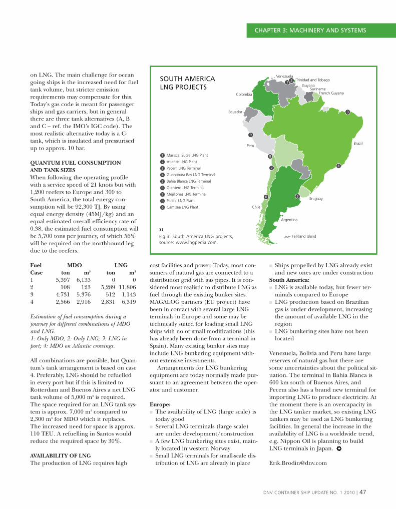
on LNG. The main challenge for oceangoing ships is the increased need for fueltank volume, but stricter emissionrequirements may compensate for this.Today’s gas code is meant for passengerships and gas carriers, but in generalthere are three tank alternatives (A, Band C – ref. the IMO’s IGC code). Themost realistic alternative today is a C-tank, which is insulated and pressurisedup to approx. 10 bar.
QUANTUM FUEL CONSUMPTIONAND TANK SIZES When following the operating profilewith a service speed of 21 knots but with1,200 reefers to Europe and 300 toSouth America, the total energy con-sumption will be 92,300 TJ. By usingequal energy density (45MJ/kg) and anequal estimated overall efficiency rate of0.38, the estimated fuel consumption willbe 5,700 tons per journey, of which 56%will be required on the northbound legdue to the reefers.
Fuel MDO LNGCase ton m3 ton m3
1 5,397 6,133 0 02 108 123 5,289 11,8063 4,731 5,376 512 1,1434 2,566 2,916 2,831 6,319
Estimation of fuel consumption during ajourney for different combinations of MDOand LNG. 1: Only MDO, 2: Only LNG; 3: LNG inport; 4: MDO on Atlantic crossings.
All combinations are possible, but Quan-tum’s tank arrangement is based on case4. Preferably, LNG should be refuelledin every port but if this is limited to Rotterdam and Buenos Aires a net LNGtank volume of 5,000 m3 is required. The space required for an LNG tank sys-tem is approx. 7,000 m3 compared to2,300 m3 for MDO which it replaces. The increased need for space is approx.110 TEU. A refuelling in Santos wouldreduce the required space by 30%.
AVAILABILITY OF LNG The production of LNG requires high
cost facilities and power. Today, most con-sumers of natural gas are connected to adistribution grid with gas pipes. It is con-sidered most realistic to distribute LNG asfuel through the existing bunker sites.MAGALOG partners (EU project) havebeen in contact with several large LNGterminals in Europe and some may betechnically suited for loading small LNGships with no or small modifications (thishas already been done from a terminal inSpain). Many existing bunker sites mayinclude LNG bunkering equipment with-out extensive investments.
Arrangements for LNG bunkeringequipment are today normally made pur-suant to an agreement between the oper-ator and customer.
Europe:� The availability of LNG (large scale) is
today good� Several LNG terminals (large scale)
are under development/construction� A few LNG bunkering sites exist, main-
ly located in western Norway� Small LNG terminals for small-scale dis-
tribution of LNG are already in place
� Ships propelled by LNG already existand new ones are under construction
South America:� LNG is available today, but fewer ter-
minals compared to Europe � LNG production based on Brazilian
gas is under development, increasingthe amount of available LNG in theregion
� LNG bunkering sites have not beenlocated
Venezuela, Bolivia and Peru have largereserves of natural gas but there aresome uncertainties about the political sit-uation. The terminal in Bahia Blanca is600 km south of Buenos Aires, andPecem also has a brand new terminal forimporting LNG to produce electricity. Atthe moment there is an overcapacity inthe LNG tanker market, so existing LNGtankers may be used as LNG bunkeringfacilities. In general the increase in theavailability of LNG is a worldwide trend,e.g. Nippon Oil is planning to buildLNG terminals in Japan.
DNV CONTAINER SHIP UPDATE NO. 1 2010 | 47
1
1
2
3
4
5
6
7
8
9
2
3
4
56
7
8
9
Trinidad and TobagoVenezuela
GuyanaSuriname
French Guyana
Brazil
Uruguay
Falkland Island
Argentina
Chile
Peru
Equador
Colombia
Mariscal Sucre LNG Plant
Atlantic LNG Plant
Pecem LNG Terminal
Guanabara Bay LNG Terminal
Bahia Blanca LNG Terminal
Quintero LNG Terminal
Mejillones LNG Terminal
Pacific LNG Plant
Camisea LNG Plant
SOUTH AMERICA LNG PROJECTS
››Fig.3: South America LNG projects, source: www.lngpedia.com.
CHAPTER 3: MACHINERY AND SYSTEMS

48 | DNV CONTAINER SHIP UPDATE NO. 1 2010
››Above: one of the two LNG tanks on board.Below: a fuelling station for the LNG ferry.
CHAPTER 3: MACHINERY AND SYSTEMS
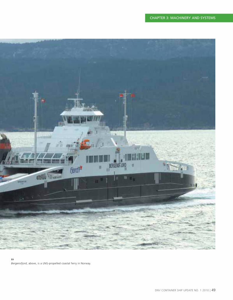
DNV CONTAINER SHIP UPDATE NO. 1 2010 | 49
››Bergensfjord, above, is a LNG-propelled coastal ferry in Norway.
CHAPTER 3: MACHINERY AND SYSTEMS
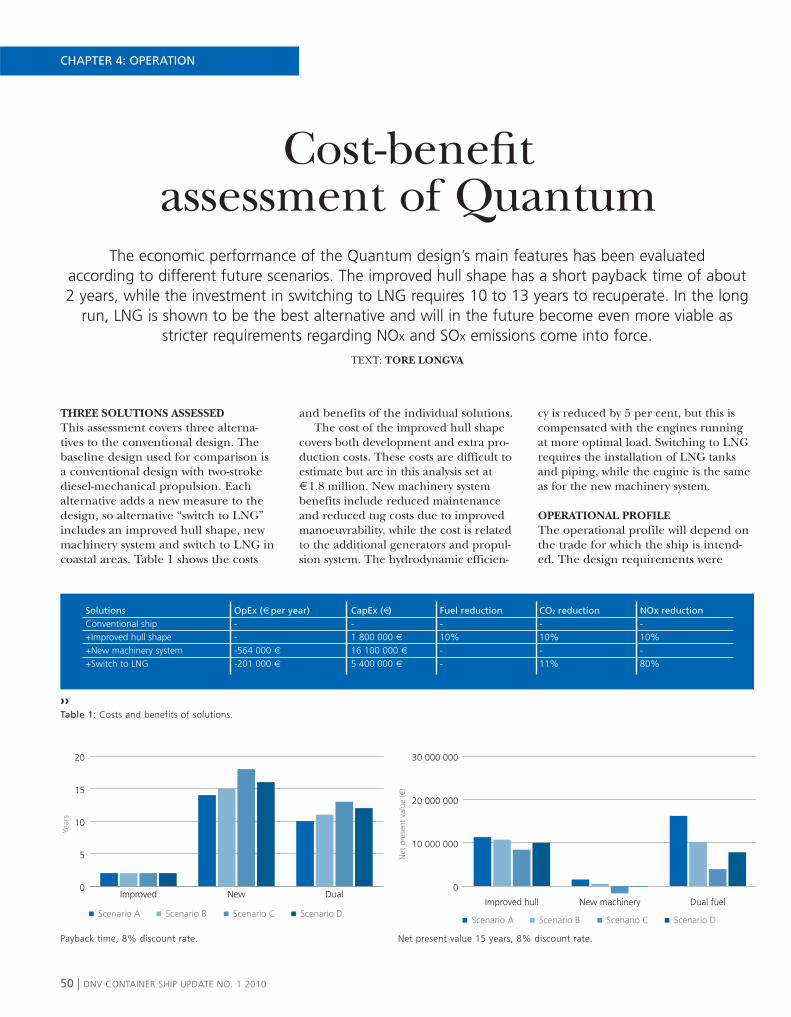
Cost-benefitassessment of Quantum
The economic performance of the Quantum design’s main features has been evaluatedaccording to different future scenarios. The improved hull shape has a short payback time of about 2 years, while the investment in switching to LNG requires 10 to 13 years to recuperate. In the long
run, LNG is shown to be the best alternative and will in the future become even more viable asstricter requirements regarding NOx and SOx emissions come into force.
TEXT: TORE LONGVA
THREE SOLUTIONS ASSESSEDThis assessment covers three alterna-tives to the conventional design. Thebaseline design used for comparison isa conventional design with two-strokediesel-mechanical propulsion. Eachalternative adds a new measure to thedesign, so alternative “switch to LNG”includes an improved hull shape, newmachinery system and switch to LNG incoastal areas. Table 1 shows the costs
and benefits of the individual solutions. The cost of the improved hull shape
covers both development and extra pro-duction costs. These costs are difficult toestimate but are in this analysis set at € 1.8 million. New machinery systembenefits include reduced maintenanceand reduced tug costs due to improvedmanoeuvrability, while the cost is relatedto the additional generators and propul-sion system. The hydrodynamic efficien-
cy is reduced by 5 per cent, but this iscompensated with the engines runningat more optimal load. Switching to LNGrequires the installation of LNG tanksand piping, while the engine is the sameas for the new machinery system.
OPERATIONAL PROFILEThe operational profile will depend onthe trade for which the ship is intend-ed. The design requirements were
50 | DNV CONTAINER SHIP UPDATE NO. 1 2010
Scenario A Scenario B Scenario C Scenario D
0
5
10
15
20
DualNewImproved
Year
s
Scenario A Scenario B Scenario C Scenario D
0
10 000 000
20 000 000
30 000 000
Dual fuelNew machineryImproved hull
Net
pre
sent
val
ue (€
)
CHAPTER 4: OPERATION
SolutionsConventional ship+Improved hull shape+New machinery system+Switch to LNG
OpEx (€ per year)---564 000 €-201 000 €
CapEx (€)-1 800 000 €16 100 000 €5 400 000 €
Fuel reduction-10%--
CO2 reduction-10%-11%
NOx reduction-10%-80%
››Table 1: Costs and benefits of solutions.
Payback time, 8% discount rate. Net present value 15 years, 8% discount rate.

based on the ship trading betweenEurope and the East Coast of SouthAmerica. The assumptions regardingthe operational profile are as follows:� 350 days on hire per year� 107 days deep-sea steaming� 107 coastal sea steaming (50% in
Europe and 50% in South America)� 136 days in port (50% in Europe and
50% in South America)
ALTERNATIVE FUTURE DEVELOPMENTSCENARIOSDesigning a ship for future demandsmust take into consideration externalfactors which influence the cost pictureand legislative requirements regarding,for example, emission levels. DNV hasdeveloped four scenarios that includesome major influencing factors, such asfuel prices, emission taxes and globaland regional emission requirements.
RESULTS The results are shown as both theexpected payback time of the investmentand the net present value after 15 years,using a discount rate of 8%. No
increased second-hand value of the ves-sel compared to the conventional designafter 15 years has been assumed.
The improved hull shape has a verylow investment compared to the reducedfuel consumption and is cost-effective inall the scenarios.
The new machinery system incurs avery high initial investment which takes along time to recover. However, whencombined with switching to LNG incoastal areas, the solution becomes moreviable and the payback time is between10–13 years depending on the scenario.Even in a worst case scenario, with lowfuel prices and no further regulations,the switch to LNG in coastal areas willpay off in the long run compared to theother solutions.
The fuel price is the main driver, butNOx and SOx requirements play a sig-nificant role in the promotion of LNG-based solutions. The advantages ofLNG will be more significant, especiallyfor ships built after 2016, when NOx
tier III will be required in ECAs andexpensive NOx reducing measures willhave to be installed.
DNV CONTAINER SHIP UPDATE NO. 1 2010 | 51
Scenario A Scenario B Scenario C Scenario D
Net
pre
cent
val
ue €
-30 000 000
-20 000 000
-10 000 000
0
1 000 000
20 000 000
30 000 000
40 000 000
50 000 000
Y20Y19
Y18Y17
Y16Y15
Y14Y13
Y12Y11
Y10Y9
Y8Y7
Y6Y5
Y4Y3
Y2Y1
Improved hull shape +New machinery +Switch to LNG
Net
pre
cent
val
ue €
-30 000 000
-20 000 000
-10 000 000
0
10 000 000
20 000 000
30 000 000
40 000 000
50 000 000
Y20Y19
Y18Y17
Y16Y15
Y14Y13
Y12Y11
Y10Y9
Y8Y7
Y6Y5
Y4Y3
Y2Y1
CHAPTER 4: OPERATION
Aggregated discounted cash flow. All solutions applied, 8% discount rate. Aggregated discounted cash flow. Scenario A, 8% discount rate.
Financial assessmentPayback timeNet present value
Case shipShip type and sizeService speedInstalled powerEngine specifications
Operational profileDays at sea/in portSpeed/engine loadArea of operation
Future scenariosFuel pricesLegislative requirementsEnvironmental taxes
Technical solutionsInvestment costOperating costReduction cost
SCENARIO DESCRIPTIONSCommon: All scenarios consider regulationswhich are already decided on. These include NOx
tier II for new engines and the 0.1% sulphurlimit for ships in EU ports and 0.5% sulphur limitfor all ships as from 2020.
Scenario A: The price of fuel, especiallyconventional fuel, will continue to grow. In 2015,South America will be designated as an ECA, withstrict limits on fuel sulphur levels. In addition, anemission trading system will be introduced,putting a cost on CO2 that starts at €20/tonne in2012 and increases to €50/tonne by 2020.
Scenario B: The prices of conventional fuels willgrow moderately, while the price of LNG willexperience little or no growth after takinginflation into consideration. A 100€ levy on fuelis introduced in 2012. South America will bedesignated as an ECA but not before 2020.
Scenario C: Fuel prices will not increase muchbut conventional fuel prices will still increasemore than the price of LNG. South America willnot be an ECA and there will be no price orother requirements on CO2 emissions.
Scenario D: All types of fuel prices will continueto rise sharply, including the price of LNG, butthere will be no other additional requirementsrelating to CO2, NOx or SOx emissions.

DNV Triple-E™:
Environmental Rating SchemeQuantum is designed to meet the highest rating – Level 1 – according to DNV’s
Environmental & Energy Efficiency Rating Scheme for ships – DNV Triple-E™. This means thatthe ship design enables world leading environmental performance by minimising the resistance
to the sea and thereby facilitating energy-efficient ship operations, as well as applyingstate-of-the-art technology for controlling all emissions to air and discharges to sea.
TEXT: PETTER ANDERSEN
Compliance with the DNV Triple-E™requirements will make a ship betterprepared for emerging environmentalregulations and industry trends. It willalso encourage and help the operatorto achieve more energy efficient shipoperations.
The quantum hull form and propul-sion system is designed such that com-pared to a reference ship with standarddesign and similar site, Quantum willhave a better calculated Energy Efficien-
cy Design Index (EEDI) score accordingto the IMO’s Guideline for EEDI. This ismainly due to its:� Increased cargo capacity due to inno-
vative hull design� A ship design with better EEDI score
than industry average will give agreater benefit to the society in termsof reduced environmental costs forthe transported goods. In addition,for a ship owner this means reducedfuel consumption which again will
reduce the fuel costs and the emis-sions to air.
BALLAST WATER TREATMENTQuantum is designed to minimise theneed for ballast water, and this can beeliminated completely by using an intelli-gent loading system. If flexible loading isa requirement, some ballast water isneeded in order to control the trim andlongitudinal strength. In such a case, anapproved Ballast Water Treatment system
52 | DNV CONTAINER SHIP UPDATE NO. 1 2010
CHAPTER 4: OPERATION

WHAT IS DNV TRIPLE-E™?DNV Triple-E™ is a rating sheme for a ships’senvironmental performance and has a rating scalefrom 4 to 1, where 1 is best. A DNV Triple-E™ ratingis accomplished through a client’s self-assessmentaccording to DNV Triple-E™ requirements, whereDNV will carry out a survey and verification leadingto a ship-specific DNV Triple-E™ Rating Declaration.The four levels of environmental performance inTriple-E™ are defined as follows:1 Leading environmental performance2 Sustained environmental performance3 Systemised environmental performance4 Heightened environmental awareness
Each level in DNV Triple-E™ has requirements withinthe three areas of: • Environmental performance of design• Environmental performance of operations• Environmental competence and leadership
All elements are equally important in order to achievea given environmental rating.
DNV Triple-E™ has been developed in response tothe increasing demand for transparency in thetransport value chain. It is intended that having ahigh DNV Triple-E™ rating in the future can be thepreferred way for a ship operator to proveenvironmental responsibility.
DNV CONTAINER SHIP UPDATE NO. 1 2010 | 53
will ensure that no organisms are takenup at one location and dumped into thesea in another part of the world, causingharm to and the contamination of themarine environment.
MATERIALSThe Quantum design facilitates compli-ance with the latest IMO Convention onShip Recycling, meaning that noasbestos, PCB or other harmful materialswill exist on board the ship. All materials
on board will be documented in anInventory of Hazardous Materials(IHM). Lightweight materials are usedin parts of the construction (such ashatch covers and piping) to reduce thelightship weight.
MINIMUM DISCHARGES TO SEAQuantum will exceed the most stringentinternational environmental requirementsapplicable to discharges of oily bilgewater, garbage and sewage to the sea:
� Oily Water Separator reducing the bilgewater oil content to less than 5 ppm.
� Garbage storage and handling systemensuring no garbage overboard
� Approved sewage treatment systemcleaning all sewage before dischargeto sea
� Sufficient tank storage capacity forsludge and other relevant dischargeproducts
43
21
Heightened awareness
Systemised
Sustained
Leading
››Fig.1: DNV Triple-E™ staircase.
Triple-E ContractClient’s
self-assessmentTriple-E Survey Triple-E Rating
1 2 3 4
CHAPTER 4: OPERATION

Since the 58 TEU ship Ideal X made itsmaiden voyage in 1956, loading andlashing methods have principallyremained the same while the carryingcapacity of the largest container shipshas surpassed 14,000 TEU. This stagger-ing increase in cargo volume has led tolonger port stays and more labour-inten-sive loading and lashing. This is a seri-ous matter for a business which is char-acterised by tight time schedules andcomplex logistics chains, where delaysoften have a direct impact – not only onfinancial results and reputations but alsoon the entire transportation networkwhich brings goods from the point ofproduction to the point of sale. Hence,more efficient cargo handling is indeedworth striving for.
The concept proposed here, whichreduces the number of crane lifts andthe need for lashing, could be a signifi-cant step towards this goal. While wait-ing for the ship to arrive in port, thecontainers are loaded into an open-frame structure which is equipped withbuilt-in stacking cones and cell guides.The loaded frame is then lifted onboard onto two adjacent containerstacks, to which it is secured by means oftwistlocks. In addition to reducing thenumber of crane lifts, this has the bene-fit of locking two stacks together so thatthe deck reaction loads – and conse-quently the lashing requirements – aresignificantly reduced.
A frame dimensioned for empty con-tainers would only weigh approximatelythree tons. The decision to design it forempty containers was based on severalconsiderations. Firstly, lifting up to eightloaded containers would be beyond thecapacity of today’s cranes. Secondly,reinforcing the frame for the carriage ofloaded containers would lead to increas-es in size and weight. Lastly, on manytrades a large number of the carriedcontainers are empty on parts of theloop. These empty containers are typi-cally stowed in the top tiers, which cor-
responds well with the proposed use ofthe frame.
Because the frame has an open top,once it is on board single containers canbe unloaded just as easily as from anordinary stack. Similarly, single contain-ers can be loaded from the quay into apartially filled frame. This means thatthe improved efficiency can be obtainedwithout sacrificing cargo handling flexi-bility. The only additional planninginvolved to allow for the use of frames isthe planning of the pairs of stacks ontop of which the frames are to be
Boxes in boxes– improved cargo handling efficiency and reduced lashing
A lightweight, open-top frame structure, capable of carrying up to eight containers,can be loaded on the quay and lifted on board in one go. This will save valuable timein port, something which is of utmost importance to shipping companies as well asshippers and terminals. Additionally, this ‘boxes in boxes’ concept can reduce the
need for container lashing and increase cargo safety.TEXT: CHRISTIAN ANDERSSON
54 | DNV CONTAINER SHIP UPDATE NO. 1 2010
CHAPTER 4: OPERATION
››Fig.1: Frame structure for empty boxes capable of carrying eight 20-foot containers, four 40-footcontainers or combinations thereof.

stowed. The stacks in each pair have tobe of equal height, meaning that caremust be taken to ensure an equal num-ber of high cubes in those particularstacks. However, should unforeseen cir-cumstances make this impossible, thecontainers that were planned to bestowed in a frame can be lifted on boardindividually. The empty frame left onthe quay can be folded for convenientstorage.
Another advantage of the concept isthat it does not require any modifica-tions to terminal facilities, lashingequipment or the existing fleet; it canbe lifted by existing cranes, secured bymeans of ordinary twistlocks and car-ried on any container ship. This is animportant feature of any innovativemeasure aimed at improving containerhandling efficiency. Container trans-portation was introduced more than
half a century ago, and the highly stan-dardised infrastructure which supportsit is truly enormous and thus very cost-ly to replace.
Apart from the boxes in boxes con-cept, a number of other measures wereevaluated in terms of efficiency and safe-ty gains as well as cost, reliability andtechnical feasibility. Some of these wereaimed at reducing the amount of lash-ing. One such method was transversecontainer stowage; however, it was foundthat the amount of transverse lashingwould not be dramatically reduced andsome additional longitudinal lashingmight be necessary. Other possiblemethods included constant-tension wirelashing, electromagnetic containersecuring and cell guides on deck. Thesewere abandoned mainly because theyinvolve the introduction of new compo-nents which would require maintenance
and which could cause delays if theyfailed.
Lastly, various ways of improvingcargo loading efficiency were proposedand investigated. One of the mostpromising ones was the side loading ofholds, which would allow the simulta-neous loading of decks and holds.However, such a concept would mostlikely require some form of on-boardcargo handling system to carry eachcontainer to its slot. Since it would beimpossible to access the containersbelow deck by means of shore cranes,failures in the on-board system wouldinevitably cause delays. The conclusionwas thus that the benefits would comeat a higher cost, in terms of possibleadverse consequences, compared tothe boxes in boxes concept.
DNV CONTAINER SHIP UPDATE NO. 1 2010 | 55
››Fig.2: Hinged sides allow folding for convenient storage when not in use.
CHAPTER 4: OPERATION

WEATHER ROUTING SYSTEMS The fuel consumption can be reducedby optimised fuel routing with respect toweather (wind, waves and current) andpower management. Calculations havebeen carried out to demonstrate theeffect of routing for the Quantumdesign. As an illustration, Fig.1 shows theoptimised route for one leg on theEurope to South America route for aspecific storm situation.
When choosing the shortest track(great circle), the captain has many dif-ferent power management alternatives:� Operate on constant rpm� Maintain the speed� Speed up before and after the storm. The different scenarios cause differentdelays (Fig.2) and fuel consumptions(Fig.3). For lesser storms, you can avoiddelays but at the cost of a higher fuelbill. For the biggest storms, it is impossi-ble to avoid a delay by choosing theshortest track. The cost of reducing thedelay from about 20 to 10 hours in theworst storm is a 20% increase in the fuelconsumption.
Another alternative is to routearound the storm, as illustrated inFig.1. The optimum distance from thestorm centre depends on the stormintensity. Assuming that the storm is
located with its centre on the great cir-cle line (shortest path), the optimumdistance (radius) from the centre isgiven in Fig.4.
It is clear that the benefit of routingincreases rapidly for storms with signifi-cant wave height above 3m. In the caseof storms with a 6m significant waveheight, the captain should sail 700kmaway from the storm centre, whichreduces the fuel consumption by 6.5%compared to the shortest track. This willdepend of course on the storm’s pathand extent.
The routing and power managementin combination need to be optimisedgiven the estimated time of arrival. Com-paring and correlating the predictionwith onboard monitoring throughonshore decision support provides con-trol over the different contributions to,and means to reduce, the fuel bill.
HULL MONITORING AND DECISION SUPPORT SYSTEMS are also a natural part of the future con-tainer ship. A hull monitoring systemshows the officer on watch the hull load-ing and trend. The purpose is to createawareness of the loading and fatiguedamage that is accumulated during oper-ation, and to confirm the effect of
changes in speed and course. Sailingtime can also be reduced by increasingspeed provided the loading is withinacceptable limits.
After the MSC Napoli container shipbroke in two, the Maritime AccidentInvestigation Branch suggested that theindustry should develop technical meansto measure whipping. Whipping is a sud-den vibration of the hull caused by bowimpacts and may have been a contribut-ing factor to the collapse of the MSCNapoli. These vibrations are not yet takeninto account when container ships arebeing designed, but the abovementionedsystems do take them into account.
A decision support system is any sys-tem on board or onshore that helps tooptimise performance and reduce thecosts and risk of unscheduled off hire.There are different systems for assessingthe fuel consumption, hull and propellerroughness, optimum trim and emissions,avoiding parametric roll and excessivemotions (Octopus and VOSS), etc. Onlya small fraction of the ships areequipped with state-of-the-art systemstoday.
Optimum ship operation or business as usual?
The operational phase makes up the main part of the ship’s life from design to scrapping. The lifetime fuel bill is several times the newbuilding cost. Cost-effective operation can be achieved
through decision support systems to reduce fuel costs and the risk of unscheduled off-hire andrepairs. In the future, better contracts between owners and charterers will be used to allow
a win-win situation regarding the fuel bill. This article demonstrates how Quantum can achieve savings of up to several per cent by using weather routing and hull monitoring.
TEXT: GAUTE STORHAUG
56 | DNV CONTAINER SHIP UPDATE NO. 1 2010
CHAPTER 4: OPERATION

DNV CONTAINER SHIP UPDATE NO. 1 2010 | 57
››Fig.1: Optimised route (red), shortest/great circle(black) and constant course/rhumb line (blue) fromPecem to Algeciras in the case of a storm with amaximum significant wave height of 5m and headsea (referring to constant course).
Fig.2: Delays for three scenarios in which theshortest distance is sailed. In this case, the captainhas also decided to speed up before enteringsignificant wave heights of more than 2.5m,thereby moving from a ‘constant rpm’ to ‘speedup’ scenario when the storm intensity increases.
Fig.3: Increased fuel consumption on shortesttrack as a function of the significant wave heightfor three different scenarios.
Fig.4: Benefit of routing and optimised distance(radius) from the storm centre as a function of themaximum significant wave height.
Fig.5: Sperry Marine with Fuel Navigator is oneexample of a supplier with a fuel routing system.Here the weather overlay (current) is shown on theECDIS system, with the optimised route reducingthe fuel consumption by 8% compared to thenormal route.
35
30
25
20
15
10
5
0 2 4 61 3 50
Significant wave height, Hs (m)
Fuel
con
sum
ptio
n in
crea
se (%
) 4
1
3
5
CHAPTER 4: OPERATION
2

1. How do you feel about DNV proposingsuch a concept study to the industry?
COMMITTEE MEMBER 4: Developmentis not possible without constructive discus-sion, and constructive discussion is ofteninitiated by a kind of provocation. In thissense, I appreciate the Quantum project.
The Quantum is on the one hand anengineering exercise based on selectedparameters (this should never be forgot-ten), which in the process led to a slight-ly futuristic result, although it is clearthat it can be achieved using today’stechniques. On the other hand, the proj-ect opens the mind for a more ‘out ofthe box’ way of thinking, which is oftenlacking in day-to-day business. In thissense, Quantum can be seen as an exam-ple and can motivate not only engineers.
COMMITTEE MEMBER 1: In view ofthe important challenge of reducingemissions and protecting our valuableenvironment, we are thankful for everypossible idea that leads to technicalimprovements.
The more experts working on thetopic, the faster we will make furtherprogress. However, it is important tounderstand that there is often a big gapbetween theory and real life. This study
could be an interesting basis for furtherdiscussion and technical research. Itshould not be understood as the oneand only thoroughly developed strategyto solve the problem. It will take a lotmore time to develop and find the mostpromising ideas and finally to design areliable product ready for the market.
2. LNG is proposed as a primary energysource for Quantum. Do you see LNG as aviable alternative for the future?
COMMITTEE MEMBER 1: As regardsemission reductions, LNG seems an inter-esting way forward. On the other hand,due to technical reasons and regulations,it leads to a loss of container-carryingcapacity. This issue needs further carefulevaluation and thorough cost-benefitanalysis as carriers want to maximise emis-sion reductions while continuing to offera reliable service to customers.
COMMITTEE MEMBER 2: In general,YES. LNG and, in the future, other nat-ural/biological gases have to be used forcombustion drives around the world.Why not on ships too? We have to han-dle the implementation phase with care,so as not to destroy the possible techni-cal advantages by too many discussions
about difficulties in front of all theinvolved parties before such a system iswell implemented.
From this point of view, it would bean advantage to implement the first stepof the Aux Eng drive in the ECA only, inorder to reduce stowage problems andguarantee safe fuel oil operations incase of any danger.
3. The public perception of danger may playa role when container ships carrying LNGcall at a port near their home, especiallyafter the recent accident at the power plantin Connecticut. How important do you con-sider public perception to be? How can thischallenge be overcome?
COMMITTEE MEMBER 3: Of course it isimportant to have this aspect in focus, butLNG carriers are also not seriously viewedby the public as an unacceptable trans-port mode (although in most cases peo-ple do not want them too close to resi-dential areas). With container ships, it isimportant to pro-actively show and provea very high safety standard and profes-sional handling of this technology inorder to eliminate any possible negativepublic perception right from the begin-ning. I would not overestimate the impor-tance of public perception in this respect,as long as the industry handles this in anappropriate and responsible way. Thismust also be seen in context – that LNGwill be far more environmentally friendly,especially for estuaries and ports.
Feedback from DNV Germantechnical committee
A concept study like Quantum will have new and novel solutions. The presentationof this study for DNV’s German technical committee resulted in a good discussion, andwe asked a few committee members to kindly summarise some reactions to the study.
CHAPTER 5: INDUSTRY FEEDBACK
58 | DNV CONTAINER SHIP UPDATE NO. 1 2010
“DEVELOPMENT IS NOT POSSIBLE WITHOUT CONSTRUCTIVEDISCUSSION, AND CONSTRUCTIVE DISCUSSION IS OFTEN INITIATEDBY A KIND OF PROVOCATION. IN THIS SENSE, I APPRECIATE THEQUANTUM PROJECT.”

4. The suggested location of the LNG storagetanks is under the superstructure. Psycho-logically, this may not be the best choice.How important is this?
COMMITTEE MEMBER 1: Basically, theLNG stowage position has to comply withthe relevant rules. From a technical pointof view, the space below the superstruc-ture seems to be ideal as no containercarrying capacity is lost. However it mightcreate acceptance problems with thecrew living “on top of the gas cylinders”.I, at least, would not feel comfortablewith this. I would urge engineers to finda more psychologically friendly stowageposition for the LNG. This should helpto gain more acceptance for this kind oftechnology.
COMMITTEE MEMBER 2: The crew hasto be informed and familiarised in detailabout the possible risks and danger fromLNG systems and storage tanks. For thetime being, the lack of information leadsto apprehension.
5. Cold ironing is a challenge when itcomes to implementation in different portsaround the world. Do you see LNG as aviable alternative?
COMMITTEE MEMBER 2: YES. Theexisting cold ironing systems around theworld (in some ports only as yet) perfect-ly reflect the difficulties of worldwidestandardisations. It is almost impossibleto install a cold ironing systems ready touse in all ports around the world withouttransformers and converters. Energy is
lost during all these processes.Further on, all combustion drives are
operated during manoeuvring using“normal” fuel oil with high emissions. Ifthe fuel oil spec is changed when enter-ing the ECA, the emissions are reducedbut the risk relating to the fuel oilchange and the additional stowagecapacity losses are counter-productive forsuch solutions too.
Using LNG or alternative gases enablesthe entire combustion machinery or auxil-liary engines and boiler (depending onthe operator’s choice & equipment) to beoperated as from entry to the ECA, whilemanoeuvring, during port stay, and out tothe end of ECA, to run with reducedemissions and without any transforminglosses or fuel oil change over risks.
CHAPTER 5: INDUSTRY FEEDBACK
DNV CONTAINER SHIP UPDATE NO. 1 2010 | 59
››Members of the German Technical Committee and representatives from DNV gathered at the roof of the DNV office in Hamburg. From left: Knut Døhlie, ChristophAmian, Jörg Langkabel, Richard von Berlepsch, Frank Jungmann, Holger Schönhoff, Wolfgang Bühr, Heino Eckerich, Thorsten Beiler, Jon Rysst, Alfred Sørensen,Jost Bergmann, Harald Schlotfeldt, Paul A. Thomson, Horst-Dieter Spang, Capt. Stefan Bülow, Prof. Stefan Krüger, Audun Grimstad, Klaus Bruckmann, FransPaardekooper, Vebjørn J. Guttormsen, Frank-Wilhelm Heidrich

6. Future legislation, including carbon taxand ECA restrictions, presents the industrywith challenges and uncertainty. Do youthink decision makers will be prepared toinvest today to meet uncertain, but probablestricter requirements, in the future?
COMMITTEE MEMBER 3: This willlargely depend on whether an earlyinvestment already makes sense, as wecannot afford to make investments inunclear technical and organisationalsolutions. As there is no doubt thatrequirements will become stricter, thereis certainly also a general preparation forinvestments in the future today. As longas it is clear that such an investment willmake sense, I am sure that the answer tothis question is YES. However, there areplenty of examples of premature invest-ments in unfinished technologies (e.g.Ballast Water Treatment Systems, InertGas Systems on tankers, etc) and thesehave to be avoided. On the other hand,it is in most cases an advantage to beable to plan investments at an early stageprovided the technical and organisation-al presuppositions are acceptable.
7. Slow steaming and extra slow steaminghave proven to be important today. Quan-tum has been designed to operate efficientlywithout modifications at speeds rangingfrom 22.5 knots down to less than 10 knots.How important will this flexibility be in thefuture? Would you be prepared to invest toachieve such flexibility?
COMMITTEE MEMBER 1: In view ofincreasing fuel oil costs and fuel oil con-nected costs, the optimum cruising speedwill be lower than in the past. This devel-opment is driven not only simply by thefuel oil price, but also by future regula-tions such as the required use ofimproved fuel oil quality and possibleGHG fees. However, I would require a
crystal ball to make an exact prediction offuture developments. Based on this uncer-tainty, carriers presently prefer to stay asflexible as possible to be prepared to copewith any future market developments.This flexibility seems especially importantsince a decision has to be based on a ves-sel’s average lifetime of 25 years.
8. How important is “carbon footprint” nowand in the future?
COMMITTEE MEMBER 3: As the indus-try is continuing to ask container lineroperators (and oil and chemical majorsare asking tanker owners etc) to providethis information, the “carbon footprint”is an important factor for the shippingindustry and will become even moreimportant in the future. This is inde-pendent of how this information is usedor misused and therefore we shouldmonitor and comment on this in orderto prevent nonsense from being used todrive certain (political) interests.
9. A commercial study of Quantum indicatesthat requirements as to emissions and higherfuel prices are prerequisites to make the con-cept commercially viable. Would the expecta-tions as to the future be enough to justifyinvestment today?
COMMITTEE MEMBER 4: In general,this is the old question of what you basean investment calculation on, whatinfluencing factors you assume andwhat ROI you expect.
In the present market, it is hard tobelieve that someone can or is willingto invest in something extra whichmight be of advantage in the future.This may change in the next few years,when the emissions’ ‘fine’ is clearerand if the oil price rises.
The present answer is slow/super slowsteaming, and new standard speedranges that are much below today’s fig-
ures can be expected to be establishedfor different container vessel sizes.
Furthermore, there is a differencebetween a vessel ordered by a liner oper-ator for its own, possibly specified trade,bearing the operational and technicallifetime cost in mind, and a fund-financed vessel that is to be charteredout and possibly have a number of differ-ent charterers during her lifetime. Ves-sels with a lot of ‘extras’ will not neces-sarily earn appropriately higher charterrates which will recoup the investment.
10. Azipods (360 degree rotation) are pro-posed for the design. These have been usedon cruise ships for several years. How will-ing would you be to consider such an alter-native for container ships?
COMMITTEE MEMBER 3: The veryhigh maintenance and repair cost ofAzipods as well as the lack of reliabilitydoes not lead me to have an optimisticview or any reason to propose Azipodsfor container ships. The commercial
advantages are quite slight (due to theobligatory use of tugs in various areasand/or for large vessels). There are farmore efficient propulsion systems thanthe one using Azipods proposed by DNVfor the Quantum project
COMMITTEE MEMBER 2: In general,container vessels from a certain sizeupwards are obliged to use TUG assis-tance in ports anyhow. Smaller vesselsare not able to accommodate the rela-tively high investment in Azipods.
A detailed cost analysis and body lineoptimisation have to be conducted toincrease the number of stability contain-ers in order to find “pro-arguments” forthe Azipods. Nevertheless, during thepast few years, the Azipods’ technical per-formance was below any acceptable level.This is still an unreliable component.
60 | DNV CONTAINER SHIP UPDATE NO. 1 2010
CHAPTER 5: INDUSTRY FEEDBACK
“LNG HAS TO BE USED FOR COMBUSTION DRIVES AROUNDTHE WORLD. WHY NOT ON SHIPS TOO?”
“WE ARE THANKFUL FOREVERY POSSIBLE IDEA THATLEADS TO TECHNICALIMPROVEMENTS.”

11. Lightweight structures have been intro-duced in various parts of the ship, resultingin a lightweight reduction of some 3,000tonnes. How willing would you be to startusing such new technology?
COMMITTEE MEMBER 2: A 3,000 t savingwas mentioned, including the reefer con-tainers. These containers do not belong tothe ship and should not be included in thecalculations in such a way just to demon-strate a possible benefit.
How much would the real weight sav-ings be on the ship body?
It seems useful to install “sandwich”plates as bulkheads in the superstructurearea only. Such design ideas are more use-ful for passenger vessels or car carriers.
12. The “wide-deck” concept providesincreased carrying capacity. Pilot access andfendering are presented as potential problems.If these points are solved by providing accessthrough the sloping part via a hatch openingand pilot ladder and fendering is solved by adrop-down inflatable solution, what otherobjections do you see to this idea?
COMMITTEE MEMBER 3: The so-called'inflatable solution' is no real solution as Isee it. Practical experience shows that it isnot a realistic scenario because handling,strength and other objections in world-wide ports show that this idea is unfortu-nately not optimal or workable. The tidesituations and pier constructions areoften not as ideal as they might seem tobe from the 'green desk'. Too much andtoo extensive damage to equipment andhulls will also most probably be the result.
COMMITTEE MEMBER 2: To me, thefendering system will continue to be dif-
ficult and maintenance-intensive equip-ment which does not exist as long theship’s body is designed in the traditionalway.
The positions of the fenders are veryinconvenient for maintenance and noreliable design is available today. Further-more, there is a very high risk involved in“setting” the upper area of the outside
shell on the quay side during tide varia-tions and loading operations. It will bevery difficult to manoeuvre such vesselsduring mooring and TUG boat opera-tions caused by decreased visibility of theship side.
The one advantage of such a design isthe better protection against piracyattacks.
DNV CONTAINER SHIP UPDATE NO. 1 2010 | 61
CHAPTER 5: INDUSTRY FEEDBACK
“BASED ON THIS UNCERTAINTY,CARRIERS PRESENTLY PREFERTO STAY AS FLEXIBLE ASPOSSIBLE TO BE PREPARED TOCOPE WITH ANY FUTUREMARKET DEVELOPMENTS.”
“IN VIEW OF INCREASING FUEL OIL COSTS AND FUEL OILCONNECTED COSTS, THE OPTIMUM CRUISING SPEED WILL BELOWER THAN IN THE PAST”
››The DNV office building is centrally located close to the business district and harbour in Hamburg. Herepictured with a detail from the Brooks Bridge in the foreground. The picture of the DNV German TechnicalCommittee (previous pages) was taken on the roof of this building.

››DNV Technical Director Olav Nortun learns about one of the extraordinaryinnovation projects from Kian Seng Tok.
››Far right: DNV’s CEO Henrik O. Madsen and Quantum project managerEirik Byklum.
››Right: Atle Ellefsen, left, and Erik Brodin, right discussing the Quantumconcept with DNV president Tor E. Svensen.
››The Quantum model.
Innovation on displaySix of the extraordinary innovation projects have been
concluded and presented in front of a commentary board includingDNV CEO Henrik O. Madsen. Container ship of the future was
one of the projects.
62 | DNV CONTAINER SHIP UPDATE NO. 1 2010
CHAPTER 5: INDUSTRY FEEDBACK

DNV CONTAINER SHIP UPDATE NO. 1 2010 | 63
Although not all the projects resultedin proposals for future DNV invest-ments, all six were well received at theexhibition held at head office on 21January, 2010.
“Very solid work went into theseprojects,” says DNV CEO Henrik O.Madsen. “Not all first ideas pass, ofcourse, but that’s typical in innovationand can lead to more ideas in thefuture. It’s important to allocate the
time and best technologists, givingthem the freedom to explore. It’s agood investment for DNV.”
Henrik O. Madsen was part of a com-mentary panel that included DNV presi-dent Tor E. Svensen, DNV TechnicalDirector Olav Nortun, Director for Clas-sification Department Eirik Andreassenand DNV Technical Director Kim Mørk.
CONTAINER SHIPS OF THE FUTURE:“We have developed a new ship design inwhich we were able to significantlyimprove on performance, efficiency andlessening the environmental impact,”says project manager, Eirik Byklum.“Now we’re in the process of moving thatdesign forward.
The six projects will be on display inthe main lobby at Høvik for those whomay be visiting.
CHAPTER 5: INDUSTRY FEEDBACK

QuantumOslo