Embed Size (px)
Citation preview
SCADAPack DNP Driver
User and Reference Manual
CONTROL MICROSYSTEMS SCADA products... for the distance
48 Steacie Drive Telephone: 613-591-1943 Kanata, Ontario Facsimile: 613-591-1022 K2K 2A9 Technical Support: 888-226-6876 Canada 888-2CONTROL

DNP3 User and Reference Manual 2 31 December 2007
©2007 Control Microsystems Inc. All rights reserved. Printed in Canada.
Trademarks
TelePACE, SCADASense, SCADAServer, SCADALog, RealFLO, TeleSAFE, SCADAPack, TeleBUS, SCADAWave and ClearSCADA are registered trademarks of Control Microsystems.
All other product names are copyright and registered trademarks or trade names of their respective owners.

DNP3 User and Reference Manual 3 31 December 2007
Table of Contents
1 USING THIS MANUAL .................................................................................. 7
2 DNP3 PROTOCOL OVERVIEW .................................................................... 8
2.1 DNP Architecture ...................................................................................... 8
2.1.1 Object Library ...................................................................................... 9 2.1.1.1 Internal Indication (IIN) Flags ......................................................... 9
2.1.2 Application Layer ............................................................................... 10
2.1.3 Pseudo-Transport Layer .................................................................... 11
2.1.4 Data Link Layer ................................................................................. 11
2.1.5 Physical Layer ................................................................................... 11
2.2 Modbus Database Mapping .................................................................... 11
2.3 SCADAPack DNP Operation Modes ....................................................... 12
3 SCADAPACK DNP OUTSTATION .............................................................. 13
3.1 How to Configure SCADAPack DNP Outstation ..................................... 13
3.1.1 Tasks to Complete ............................................................................. 14
3.1.2 Enable DNP on Communication Interface ......................................... 14
3.1.3 Configure DNP Outstation ................................................................. 14
3.1.4 Confirm Successful Configuration ..................................................... 18
4 SCADAPACK DNP MASTER ...................................................................... 20
4.1 SCADAPack DNP Master Concepts ....................................................... 20
4.1.1 SCADAPack DNP Mimic Master ....................................................... 21
4.1.2 SCADAPack DNP Address Mapping ................................................. 23
4.2 How to Configure SCADAPack DNP Master .......................................... 24
4.2.1 Tasks to Complete ............................................................................. 24
4.2.2 Configuration Steps ........................................................................... 24
4.2.3 Confirm Successful DNP Master Configuration ................................. 27
4.3 How to Configure SCADAPack Address Mapping .................................. 28
4.4 How to Configure SCADAPack DNP Mimic Master ................................ 29
5 SCADAPACK DNP ROUTER ...................................................................... 30
5.1 How to Configure a SCADAPack DNP Router ........................................ 31
5.1.1 Tasks to Complete ............................................................................. 31
5.1.2 Configuration Steps ........................................................................... 31

DNP3 User and Reference Manual 4 31 December 2007
6 DESIGN CONSIDERATIONS ...................................................................... 35
6.1 Considerations of DNP3 Protocol and SCADAPack DNP Driver ............ 35
6.1.1 Unsolicited Messages always request for a Confirmation ................. 35
6.1.2 Master shall never request for Application Layer Confirmation ......... 35
6.1.3 DNP Write Messages always request for a Confirmation .................. 35
6.1.4 Only one DNP3 transaction can be pending at a time ....................... 35
6.1.5 SCADAPack controllers buffer 3 DNP messages .............................. 36
6.1.6 Output points in DNP Address Mapping issue DNP Write ................. 36
6.2 Typical Configuration Malpractices and Recommendations ................... 36
6.2.1 Multiple High Priority Unsolicited Messages ...................................... 37
6.2.2 Master not polling frequently causing event buffer overflows ............ 38
6.2.3 Outstation reports to Multiple Masters with Poor Comms .................. 38
6.2.4 Insufficient Use of Input Deadband or Debounce .............................. 38
6.2.5 Master Confirmation and Retries ....................................................... 38
6.2.6 Outstation Confirmations and Retries ................................................ 39
6.2.7 Setting relatively large Application Layer timeouts ............................ 40
6.2.8 DNP Address mapping contains multiple output points ..................... 40
6.3 Configuration FAQ .................................................................................. 41
7 DNP CONFIGURATION MENU REFERENCE ............................................ 44
7.1 Application Layer Configuration .............................................................. 45
7.2 Data Link Layer Configuration ................................................................ 50
7.3 Master ..................................................................................................... 53
7.4 Master Poll .............................................................................................. 54
7.4.1 Add/Edit Master Poll Dialog ............................................................... 55
7.4.2 Poll Offset Example ........................................................................... 59
7.5 Address Mapping .................................................................................... 60
7.5.1 Add/Edit Address Mapping Dialog ..................................................... 62
7.6 Routing ................................................................................................... 63
7.6.1 Add/Edit DNP Route Dialog ............................................................... 65
7.6.2 Dynamic Routing ............................................................................... 66
7.7 Binary Inputs Configuration ..................................................................... 66
7.7.1 Adding Binary Inputs ......................................................................... 68
7.8 Binary Outputs Configuration .................................................................. 69
7.8.1 Adding Binary Outputs ....................................................................... 70
7.9 16–Bit Analog Inputs Configuration......................................................... 72

DNP3 User and Reference Manual 5 31 December 2007
7.9.1 Adding 16-Bit Analog Inputs .............................................................. 73
7.10 32-Bit Analog Inputs Configuration ......................................................... 75
7.10.1 Adding 32-Bit Analog Inputs .............................................................. 76
7.11 Short Floating Point Analog Inputs ......................................................... 78
7.11.1 Adding Short Floating Point Analog Inputs ........................................ 80
7.12 16-Bit Analog Outputs Configuration....................................................... 82
7.12.1 Adding 16-Bit Analog Outputs ........................................................... 83
7.13 32-Bit Analog Outputs Configuration....................................................... 84
7.13.1 Adding 32-Bit Analog Outputs ........................................................... 85
7.14 Short Floating Point Analog Outputs ....................................................... 87
7.14.1 Adding Short Floating Point Analog Outputs ..................................... 88
7.15 16–Bit Counter Inputs Configuration ....................................................... 89
7.15.1 Adding 16-Bit Counter Inputs ............................................................ 91
7.16 32-Bit Counter Inputs Configuration ........................................................ 93
7.16.1 Adding 32-Bit Counter Inputs ............................................................ 94
8 DNP DIAGNOSTICS .................................................................................... 97
8.1 DNP Status ............................................................................................. 97
8.1.1 Overview Tab .................................................................................... 98
8.1.2 Point Status Tabs .............................................................................. 99
8.2 DNP Master Status ............................................................................... 100
8.2.1 All Stations Tab ............................................................................... 101
8.2.2 Remote Overview Tab ..................................................................... 102
8.2.3 Remote Point Status Tabs ............................................................... 104
9 DNP MASTER DEVICE PROFILE DOCUMENT ....................................... 105
10 DNP SLAVE DEVICE PROFILE DOCUMENT .......................................... 115

DNP3 User and Reference Manual 6 31 December 2007
Document Revision
Revision Date Modification Author
1.10 12 July 2007 Added Configuration Steps for major DNP Operation modes.
Added chapter on best design practices.
KN
1.20 December 17, 2007 Added Unsolicited Back Off Time documentation.
DG

DNP3 User and Reference Manual 7 31 December 2007
1 Using This Manual The manual details implementation of the Distributed Network Protocol (DNP3) driver on SCADAPack controllers. While we continuously improve upon the contents of this manual to simply the driver configuration tasks, we also assume that users attempting to configure the DNP protocol on a SCADAPack controller have some preliminary understanding of the DNP3 communication protocol.
The manual is arranges as follows:
Section 2 describes typical DNP3 networks that can be architected using SCADAPack controllers.
Section 3 discusses the concept and configuration of a SCADAPack DNP Outstation.
Section 4 discusses the concept and configuration of a SCADAPack DNP Master.
Section 5 discusses the concept and configuration of a SCADAPack DNP Router.
Section 6 proposes some considerations and best practices to consider when setting up a DNP network using SCADAPack controllers.
Section 7 provides a complete reference for the DNP Configuration panel.
Section 8 provides a complete reference for the DNP diagnostic tools.
Sections 9 and 10 contain device profiles for a SCADAPack DNP master and slave station. All objects and function codes supported by the DNP master are listed in this document.

DNP3 User and Reference Manual 8 31 December 2007
2 DNP3 Protocol Overview DNP, the Distributed Network Protocol, is a standards-based communications protocol developed to achieve interoperability among systems in the electric utility, oil & gas, water/waste water and security industries. This robust, flexible non-proprietary protocol is based on existing open standards to work within a variety of networks.
DNP offers flexibility and functionality that go far beyond conventional communications protocols. Among its robust and flexible features DNP 3.0 includes:
Multiple data types (Data Objects) may be included in both request and response messages.
Multiple master stations are supported for outstations.
Unsolicited responses1 may be initiated from outstations to master stations.
Data types (Objects) may be assigned priorities (Class) and be requested based on the priority.
Addressing for over 65,000 devices on a single link.
Time synchronization and time-stamped events.
Broadcast messages.
Data link and application layer confirmation
Internal indications that report the health of a device and results of last request.
Select-Before-Operate which is the ability to choose extra reliability when operating outputs.
2.1 DNP Architecture
DNP is a layered protocol that is based on the Open System Connection (OSI) 7-layer protocol. DNP supports the physical, data link and application layers only and terms this the Enhanced Performance Architecture (EPA). In addition to these three layers an additional layer, the pseudo-transport layer, is added to allow for larger application layer messages to be broken down into smaller frames for the data link layer to transmit.
Object Library The data objects (Binary Inputs, Binary Outputs, and Analog Inputs etc.) that reside in the master or outstation.
Application Layer Application tasks for sending of solicited requests (master messages) to outstations or sending of unsolicited responses from outstations. These request and response messages are referred to as fragments in DNP.
Pseudo-Transport Layer Breaks the application layer messages into smaller packets that can be handled by the data link layer. These packets are referred to as frames in DNP.
Data Link Layer Handles the transmission and reception of data frames across the physical layer.
Physical Layer This is the physical media, such as serial or Ethernet, which DNP communicates.
These layers are described in the following sections of this manual.
1 Unsolicited responses are also known as unsolicited messages

DNP3 User and Reference Manual 9 31 December 2007
2.1.1 Object Library
The data types that are used in DNP are broadly grouped together into Object Groups such as Binary Input Objects and Analog Input Objects etc. Individual data points, or objects within each group, are further defined using Object Variations such as Binary Input Change with Time and 16-Bit Analog Inputs for example. The data objects and variations supported by the SCADAPack series controllers are found in sections 9 and 10 .
In general there are two categories of data within each data type, static objects and event objects. Static objects contain the current value of the field point or software point. Event objects are generated as a result of the data changing.
In addition to the object group and variation data objects can be assigned to classes. In DNP there are four object classes, Class 0, Class 1, Class 2 and Class 3. Class 0 contains all static data. Classes 1, 2 and 3 provide a method to assign priority to event objects. While there is no fixed rule for assigning classes to data objects typically class 1 is assigned to the highest priority data and class 3 is assigned to the lowest priority data.
This object library structure enables the efficient transfer of data between master stations and outstations. The master station can poll for high priority data (class 1) more often than it polls for low priority data (class 3). As the data objects assigned to classes is event data when the master polls for a class only the changed, or event data, is returned by the outstation. For data in an outstation that is not assigned a class the master uses a class 0 poll to retrieve all static data from the outstation.
DNP allows outstations to report data to one or more master stations using unsolicited responses (report by exception) for event data objects. The outstation reports data based on the assigned class of the data. For example the outstation can be configured to only report high priority class 1 data.
2.1.1.1 Internal Indication (IIN) Flags
An important data object is the Internal Indications (IIN) object. The Internal Indication (IIN) flags are set by a slave station to indicate internal states and diagnostic results. The following tables show the IIN flags supported by SCADAPack controllers. All bits except Device Restarted and Time Synchronization required are cleared when the slave station receives any poll or read data command.
The IIN is set as a 16 bit word divided into two octets of 8 bits. The order of the two octets is:
First Octet Second Octet
2.1.1.1.1 IIN First Octet
6 5 4 3 2 1 07 Bit Number
First Octet Bit
Description
0 last received message was a broadcast message
1 Class 1 data available

DNP3 User and Reference Manual 10 31 December 2007
First Octet Bit
Description
2 Class 2 data available
3 Class 3 data available
4 Time Synchronization required
5 not used (returns 0)
6 Device trouble
Indicates memory allocation error in the slave, or
For master in mimic mode indicates communication failure with the slave device.
7 Device restarted (set on a power cycle)
2.1.1.1.2 IIN Second Octet
6 5 4 3 2 1 07 Bit Number
Second Octet Bit
Description
0 Function Code not implemented
1 Requested object unknown or there were errors in the application data
2 Parameters out of range
3 Event buffer overflowed Indicates event buffer overflow in the slave or master. The slave will set this bit if the event buffer in the slave is overflowed. The master will set this bit if the event buffer in the master has overflowed with events read from the slave. Ensure the event buffer size, in the master and slave, is set to a value that will ensure the buffer does not overflow and events are lost.
4 not used (returns 0)
5 not used (returns 0)
6 not used (returns 0)
7 not used (returns 0)
2.1.2 Application Layer
The application layer in DNP is responsible for the processing of complete messages for requesting, or responding to requests, for data.
The following shows the sequence of Application Layer messages between one master and one outstation.
Master Outstation
Send Request --------------------> Accept request and process
<-------------------- Optional Application Confirmation

DNP3 User and Reference Manual 11 31 December 2007
Accept response <-------------------- Send Response Optional Application Confirmation -------------------->
Important change detected
Accept response <--------------------- Send Unsolicited Response Optional Application Confirmation -------------------->
The complete messages are received from and passed to the pseudo-transport layer. Application layer messages are broken into fragments with each fragment size usually a maximum of 2048 bytes. An application layer message may be one or more fragments in size and it is the responsibility of the application layer to ensure the fragments are properly sequenced.
Application layer fragments are sent with or without a confirmation request. When a confirmation is requested the receiving device replies with a confirmation indicating the message was received and parsed without any errors.
2.1.3 Pseudo-Transport Layer
The pseudo-transport layer formats the larger application layer messages into smaller packets that can be handled by the data link layer. These packets are referred to as frames in DNP. The pseudo-transport layer inserts a single byte of information in the message header of each frame. This byte contains information such as whether the frame is the first or last frame of a message as well as a sequence number for the frame.
2.1.4 Data Link Layer
The data link layer handles the transmission and reception of data frames across the physical layer. Each data link frame contains a source and destination address to ensure the receiving device knows where to send the response. To ensure data integrity data link layer frames contain two CRC bytes every 16 bytes.
Data link layer frames are sent with or without a confirmation request. When a confirmation is requested the receiving device replies with a confirmation indicating the message was received and the CRC checks passed.
2.1.5 Physical Layer
The physical layer handles the physical media, such as serial or Ethernet, which DNP communicates.
2.2 Modbus Database Mapping
In SCADAPack controllers static DNP objects such as binary input, analog input, binary counter and analog output are associated with Modbus registers. Whenever a DNP object is created an associated Modbus register(s) is also assigned. Application programs executing in the SCADAPack controller, C or logic, are able to assign physical I/O to Modbus registers using the TelePACE Register Assignment or the ISaGRAF I/O Connection and these physical I/O points can then be assigned to DNP objects. User application data such as runtimes, flow totals etc. may be also be assigned to DNP objects.

DNP3 User and Reference Manual 12 31 December 2007
This architecture enables DNP master stations and outstations to pass not only physical data points between them but also to monitor and control user applications executing in the SCADAPack controller. For example a master station can monitor a level in an outstation and then, based on the application program, send a setpoint value to another outstation to control the level.
2.3 SCADAPack DNP Operation Modes
Within a DNP network, a SCADAPack controller can operate as a:
DNP Outstation (Slave)
DNP Master or Mimic Master or
DNP Router
DNP Master Mimic and DNP Router are incompatible and mutually-exclusive modes of operation.
A DNP outstation forms the basic class of any DNP node in a network. All other operational modes derive from a DNP Outstation. A DNP outstation responds to requests from one or more DNP master stations on a network. Also, a DNP Outstation is able to initiate unsolicited responses (messages) based on event data to a master station.
A DNP Master is capable of polling for data, accepting and processing unsolicited messages, and sending control commands to an outstation. Note that a DNP Master can also act perform all the duties of a DNP Outstation.
A SCADAPack controller acting as a DNP Router is simply acting a pass through, basically redirecting messages from one DNP node to another. Similarly to a DNP Master, a DNP Router can also perform all the duties of a DNP Outstation.
DNP Network topologies comprise several combinations of DNP Masters, DNP Routers, and DNP Outstations. Typical configurations possible with SCADAPack controllers are:
DNP Master and single DNP Outstation
DNP Master and multi-dropped DNP Outstations
DNP SCADA Host, Data Concentrator (Mimic Master) and multi-dropped DNP Outstations
DNP SCADA Host, DNP Router and multi-dropped DNP Outstations
Major SCADAPack DNP operation modes are covered in the next chapters.
DNP3 User and Reference Manual 13 31 December 2007
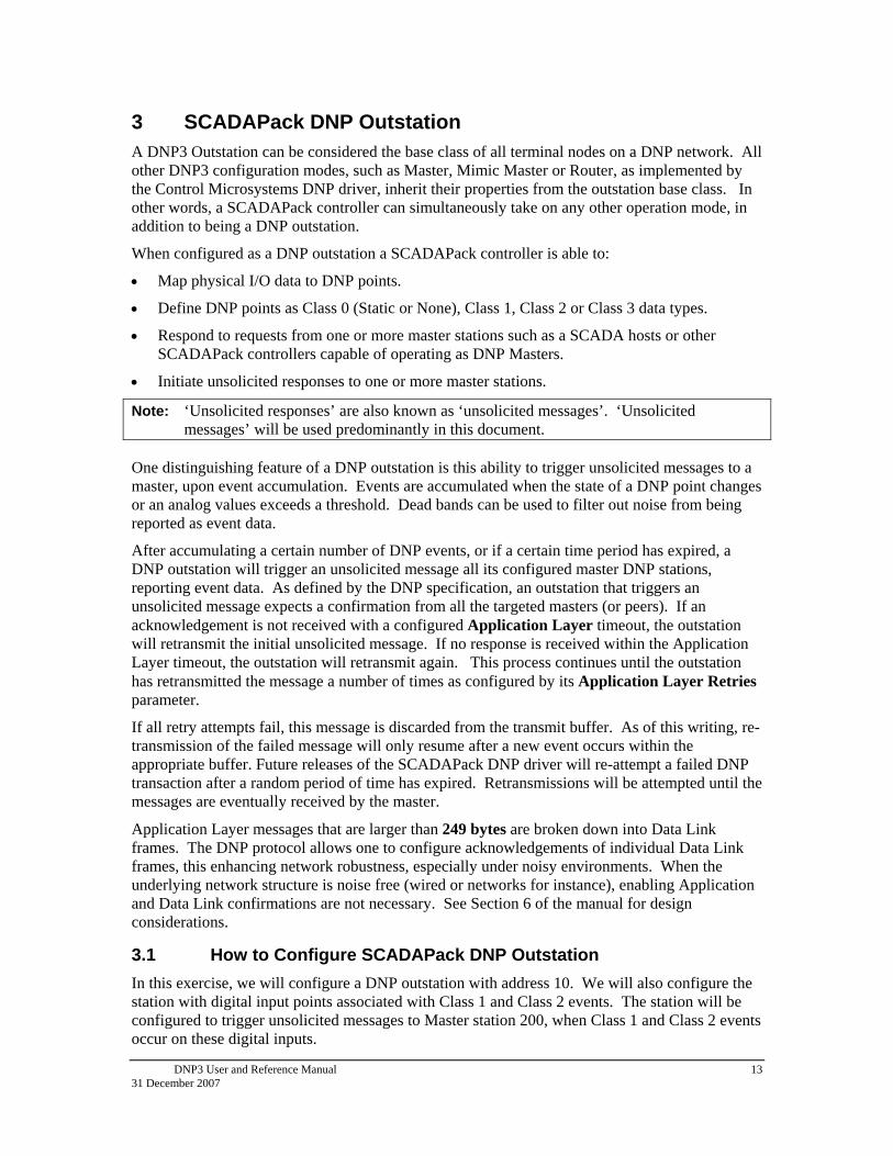
3 SCADAPack DNP Outstation A DNP3 Outstation can be considered the base class of all terminal nodes on a DNP network. All other DNP3 configuration modes, such as Master, Mimic Master or Router, as implemented by the Control Microsystems DNP driver, inherit their properties from the outstation base class. In other words, a SCADAPack controller can simultaneously take on any other operation mode, in addition to being a DNP outstation.
When configured as a DNP outstation a SCADAPack controller is able to:
Map physical I/O data to DNP points.
Define DNP points as Class 0 (Static or None), Class 1, Class 2 or Class 3 data types.
Respond to requests from one or more master stations such as a SCADA hosts or other SCADAPack controllers capable of operating as DNP Masters.
Initiate unsolicited responses to one or more master stations.
Note: ‘Unsolicited responses’ are also known as ‘unsolicited messages’. ‘Unsolicited messages’ will be used predominantly in this document.
One distinguishing feature of a DNP outstation is this ability to trigger unsolicited messages to a master, upon event accumulation. Events are accumulated when the state of a DNP point changes or an analog values exceeds a threshold. Dead bands can be used to filter out noise from being reported as event data.
After accumulating a certain number of DNP events, or if a certain time period has expired, a DNP outstation will trigger an unsolicited message all its configured master DNP stations, reporting event data. As defined by the DNP specification, an outstation that triggers an unsolicited message expects a confirmation from all the targeted masters (or peers). If an acknowledgement is not received with a configured Application Layer timeout, the outstation will retransmit the initial unsolicited message. If no response is received within the Application Layer timeout, the outstation will retransmit again. This process continues until the outstation has retransmitted the message a number of times as configured by its Application Layer Retries parameter.
If all retry attempts fail, this message is discarded from the transmit buffer. As of this writing, re-transmission of the failed message will only resume after a new event occurs within the appropriate buffer. Future releases of the SCADAPack DNP driver will re-attempt a failed DNP transaction after a random period of time has expired. Retransmissions will be attempted until the messages are eventually received by the master.
Application Layer messages that are larger than 249 bytes are broken down into Data Link frames. The DNP protocol allows one to configure acknowledgements of individual Data Link frames, this enhancing network robustness, especially under noisy environments. When the underlying network structure is noise free (wired or networks for instance), enabling Application and Data Link confirmations are not necessary. See Section 6 of the manual for design considerations.
3.1 How to Configure SCADAPack DNP Outstation
In this exercise, we will configure a DNP outstation with address 10. We will also configure the station with digital input points associated with Class 1 and Class 2 events. The station will be configured to trigger unsolicited messages to Master station 200, when Class 1 and Class 2 events occur on these digital inputs.
DNP3 User and Reference Manual 14 31 December 2007
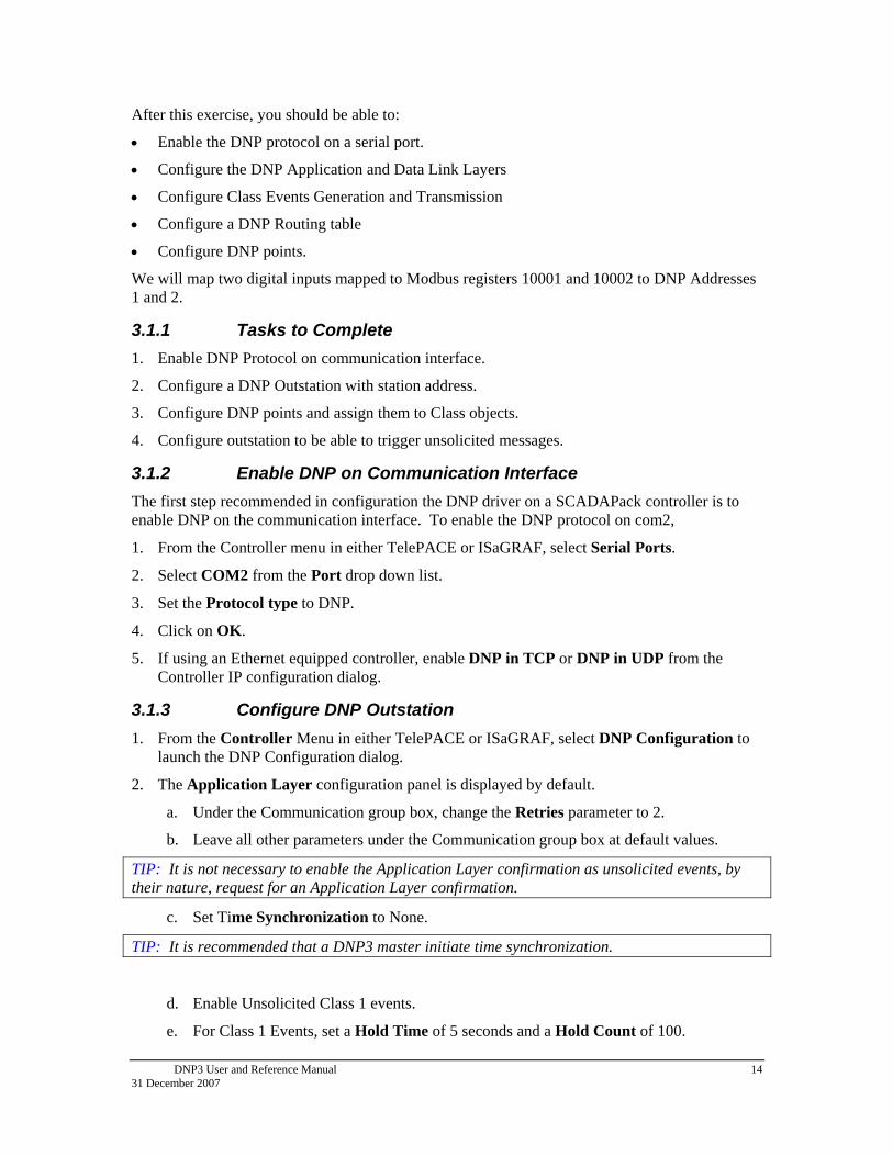
After this exercise, you should be able to:
Enable the DNP protocol on a serial port.
Configure the DNP Application and Data Link Layers
Configure Class Events Generation and Transmission
Configure a DNP Routing table
Configure DNP points.
We will map two digital inputs mapped to Modbus registers 10001 and 10002 to DNP Addresses 1 and 2.
3.1.1 Tasks to Complete
1. Enable DNP Protocol on communication interface.
2. Configure a DNP Outstation with station address.
3. Configure DNP points and assign them to Class objects.
4. Configure outstation to be able to trigger unsolicited messages.
3.1.2 Enable DNP on Communication Interface
The first step recommended in configuration the DNP driver on a SCADAPack controller is to enable DNP on the communication interface. To enable the DNP protocol on com2,
1. From the Controller menu in either TelePACE or ISaGRAF, select Serial Ports.
2. Select COM2 from the Port drop down list.
3. Set the Protocol type to DNP.
4. Click on OK.
5. If using an Ethernet equipped controller, enable DNP in TCP or DNP in UDP from the Controller IP configuration dialog.
3.1.3 Configure DNP Outstation
1. From the Controller Menu in either TelePACE or ISaGRAF, select DNP Configuration to launch the DNP Configuration dialog.
2. The Application Layer configuration panel is displayed by default.
a. Under the Communication group box, change the Retries parameter to 2.
b. Leave all other parameters under the Communication group box at default values.
TIP: It is not necessary to enable the Application Layer confirmation as unsolicited events, by their nature, request for an Application Layer confirmation.
c. Set Time Synchronization to None.
TIP: It is recommended that a DNP3 master initiate time synchronization.
d. Enable Unsolicited Class 1 events.
e. For Class 1 Events, set a Hold Time of 5 seconds and a Hold Count of 100.

DNP3 User and Reference Manual 15 31 December 2007
TIP: On systems with multiple outstations that could potentially transmit unsolicited messages to a master at the same time, it is recommended to use a combination of the Hold Time and Hold Count parameters to avoid multiple stations from transmitting at the same time.
f. Enable Unsolicited Class 2 events.
g. For Class 2 Events, set a Hold Time of 3600 seconds and a Hold Count of 10.
TIP: Class 2 events are typically of less importance than Class 1 events and may not need to be reported immediately to the master
h. All other parameters can be left at their default values. The completed Application Layer Configuration panel should look like this:
Note: Clicking on OK closes the DNP Configuration dialog. Click on OK only after you have completed the DNP configuration.
3. From the DNP Configuration panel, select the Data Link Layer tree node.
a. Click on the Edit button and change the Master Station Address to 200.
b. Change the RTU Station Address to 10.

DNP3 User and Reference Manual 16 31 December 2007
c. Leave all other parameters at their default values. The completed dialog should look like this:
TIP: It may be necessary to enable the Data Link confirmation on noisy networks. However, if the Maximum Application Fragment Length is reduced to 249 bytes, it is not necessary to enable the Data Link confirmation, as each data link packet is in essence an Application Layer fragment.
4. From the DNP Configuration panel, select the Routing tree node.
a. Click on the Add button to begin a new routing table entry.
b. From the Add/Edit Route dialog,
i. Enter 200 for the destination Station.
ii. Set the Port to COM2.
iii. Leave default values for all other parameters.
iv. The completed dialog should look like this:

DNP3 User and Reference Manual 17 31 December 2007
Note: The Data Link Timeout in this dialog takes precedence over the Data Link Timeout in the Data Link Layer configuration panel.
TIP: Even though a SCADAPack outstation will respond successfully to master request, without is routing entry to the master, it is a good practice to always define such a routing entry from an outstation to its master. Moreover, without a routing entry defined to the master, the outstation will not know which port to send out unsolicited messages, if configured, to the master.
v. Click on OK to add this entry to the routing table and return to the Routing dialog.
The completed routing table should look like this:
This next step assumes you have digital inputs mapped to Modbus registers 10001 and 10002.
5. From the DNP Configuration Panel, click on the Binary Inputs tree node.
a. Set the Starting DNP Address to 1.
b. Set the Event Report Method to Log All Events.
Note: If you want to log all events and not only the most recent, you must set the Event Reporting Method to Log all Events.
c. Set the Event Buffer Size to 100. The completed panel should look like this:
d. Click on Add to create a new DNP3 binary input point. Observe that a new binary input point is now visible under the Binary Input tree node with DNP Address 1 (Starting Address)
e. Leave the default associating Modbus Address as 10001.
f. Leave the default Event Object as Class 1.
g. Set the Debounce property to 10.

DNP3 User and Reference Manual 18 31 December 2007
TIP: It is a good idea to set a non- zero Debounce on unfiltered inputs, to avoid noise being collected as Class events. The same applies for analog inputs. A non-zero Deadband will prevent noise from being collected as Class events.
i. Set the Debounce property to 10.
j. Click on Add to submit this point to the database and start configuration for the next point. Note that a new point has been added under the Binary Inputs tree node in the DNP Configuration panel.
k. Change the associating Modbus Address to 10002.
l. Change the Event Object to Class 2.
m. Set the Debounce appropriately.
n. Click on Add to submit this point to the database and start configuration for the next point.
o. Repeat the previous two steps to add more points if desired.
p. Follow a similar procedure to configure other types of DNP3 objects.
3.1.4 Confirm Successful Configuration
To confirm that the DNP driver has been properly configured,
1. From the Controller menu, select DNP Status. You will be presented with the following dialog.

DNP3 User and Reference Manual 19 31 December 2007
2. Ensure that the DNP Status field within this dialog displays 07: enabled, configured, running
3. You can also monitor the current state of the defined DNP binary input points from the Binary-In tab.
4. Toggle the state of digital input 1 configured earlier in this exercise and observe the event buffer for Binary Inputs increment on each change of state. After 5 seconds has elapsed, notice that an unsolicited DNP message is triggered to master station 200. Given that DNP master station 200 is not yet configured and connected, a response to the unsolicited message will not be received and the 5000ms Application layer timeout period will expire. The unsolicited message transmission will subsequently retransmitted and will be aborted after 3 retry attempts have been made. This confirms that your outstation is properly setup and unsolicited messages are being generated and sent. At the time of this implementation, the events will be re-attempted only after a new event occurs.
5. Also observe the Internal Indications show that Class 1 events are available as indicated in the figure below.
For additional information on the any of the dialogs referenced in the above exercise, refer to the DNP Configuration Menu Reference towards the end this booklet.

DNP3 User and Reference Manual 20 31 December 2007
4 SCADAPack DNP Master DNP master modes currently apply only to the SCADAPack 32, SCADAPack 350 and SCADASense 4203 controllers.
As a master, a SCADAPack controller can be a regular Master or Mimic master.
4.1 SCADAPack DNP Master Concepts
A DNP Master station inherits all the characteristics of a DNP Outstation. In addition, a DNP Master station is able to:
Poll DNP outstations for static (Class 0) data and Class 1, 2 and 3 event data.
Accept and process unsolicited response messages from polled outstations.
This configuration of a DNP Master (Client) and DNP Outstation (Server) forms the basis of a DNP3 Network. The SCADAPack DNP Master may be configured to periodically poll a SCADAPack DNP Outstation for Class 0, 1, 2, and 3 data objects and receive unsolicited responses from the outstation. The outstation may be configured to report change event data to the master station using unsolicited responses.
The arrowed line between the master and outstation in the diagram below represents a communication path connecting the two stations. This communication medium may be any type that is supported by both controllers, such as direct serial, leased line modem, dial-up modem and radio for example.
SCADAPackDNP Master
SCADAPackDNP Outstation
Figure 4-1: Simple SCADAPack Master-Outstation DNP Network
An extension of a simple DNP Master and single outstation network, involves a SCADAPack DNP Master connected to a number of outstations over a multi-drop communication channel. The DNP Master may be configured to periodically poll each SCADAPack DNP Outstation for Class 0, 1, 2, and 3 data objects and receive unsolicited responses from the outstations. The outstations may be configured to report change event data to the master station using unsolicited responses.
The arrowed line between the master and outstations, in the diagram below, represents the communication path connecting the stations. This communication path may be any multi-dropped type that is supported by the controllers, such as leased line modem, dial-up modem and radio for example.
SCADAPack DNP Master
SCADAPackDNP Outstation A
SCADAPackDNP Outstation A
SCADAPackDNP Outstation A
Figure 4-2: SCADAPack DNP Master and multi-dropped DNP Outstations

DNP3 User and Reference Manual 21 31 December 2007
Note: The DNP Master feature is limited to a SCADAPack32, SCADAPack 350 and SCADASense 4203
4.1.1 SCADAPack DNP Mimic Master
In a typical DNP network a SCADA Host master communicates with a number of outstations. The SCADA Host will poll each outstation for data and may receive change event data in the form of unsolicited responses from the outstations. This type of DNP network is shown in the following diagram.
SCADAPack
DNP Outstation ASCADAPack
DNP Outstation B DNP SCADA Host
Figure 4-3: DNP SCADA Host and multi-dropped DNP Outstations
In the above configuration the SCADA Host manages the communication path with each outstation. When the communication path is slow, such as with dial-up communication, or subject to high error rates, such as with some radio communication, the data update rate at the SCADA host can become very slow.
Adding a SCADAPack controller configured for Master Mimic Mode, allows for the SCADA Host to poll the SCADAPack (Mimic Master) for all outstation data instead. In essence, the SCADAPack Mimic Master is acting as a Data Concentrator, reporting on behalf of all the outstations currently configured in its routing table. The following diagram shows the addition of the SCADAPack Mimic Master.
SCADAPack Mimic
SCADAPackDNP Outstation A
SCADAPackDNP Outstation B
DNP SCADA Host
Slave Master
Figure 4-4: SCADAPack Mimic Master and multi-dropped DNP Outstations
In this configuration the outstation side of the network has been decoupled from the host side of the network, as the SCADAPack mimic master now manages all the communication with the outstations.
The SCADA Host and all outstations will typically be connected to different communication ports of the SCADAPack Mimic Master. The mimic will respond to the following DNP messages on behalf of the targeted station:
Read messages (this includes class polls as well as individual point reads) from SCADA Host
Write messages from SCADA Host
Unsolicited messages from an outstation

DNP3 User and Reference Manual 22 31 December 2007
Direct operate messages from SCADA Host
The following DNP messages cannot be mimicked (Mimic does not respond on behalf of target DNP station), and are routed directly to the target outstation by the Mimic:
Select and Operate messages
Data Link Layer messages (e.g. get link status, reset link status, etc)
Enable/Disable Unsolicited Message commands (FC 20 and 21)
Other control messages
Routing for those messages that cannot be mimicked is subjected to the following rule:
if (a message is received which needs to be retransmitted to someone else) if (the message target is configured in our routing table) if (the destination port is different from the incoming port) or (routing is enabled on the incoming port) then retransmit the message In order to provide current outstation data to the SCADA Host, the SCADAPack mimicking master independently communicates with each outstation to update a local copy of its database with data from the outstations. This communication may be initiated by the SCADAPack mimicking master, either by polling each outstation in turn using solicited messages; or the outstations could initiate unsolicited messages back to the mimicking master. There could also be a combination of solicited and unsolicited messages between the mimicking master and the outstations.
In the Mimic mode diagram above the SCADAPack mimic master polls each outstation, A and B, for data and holds images of this data in its memory. When the SCADA Host poll outstations A and B for data, the mimic master replies from its own images of the outstations. The SCADA Host can also poll the SCADAPack master for its own local data.
Typically the messaging strategy chosen will depend on the relative importance of the data, and the required maximum end-to-end delays for data being transferred through the network. If the requirement is for a reasonably short end-to-end delay for all data points, a round-robin polling scheme is best, without any unsolicited messages. If there are some data points, which are higher priority and must be transferred as fast as possible, unsolicited messages should be used.
The advantage of having the SCADA system communicating with the SCADAPack 32 mimic, instead of direct communication to the outstations is that communication delays and high error rates are effectively removed. The physical connection between the SCADA system and mimic master SCADAPack is typically a direct high-speed reliable connection and all message transactions are fast. Outstations may often be connected via slow PSTN or radio links, and therefore message transactions are subject to substantial delays. They may also be unreliable communication links subject to high error rates.
By having a multiple-level network the communication between the SCADAPack master and outstations is separated from communication between SCADA system and the SCADAPack master. The delays and error rates, which may be inherent in the outstation communication paths, can be isolated from communications with the SCADA system, thereby increasing overall system performance.
One particular advantage of Mimic Mode is that the master SCADAPack does not need to know, or be configured with, any details of the DNP points configured in the outstations. This makes it relatively simple to insert such a SCADAPack master into any existing DNP network. The SCADAPack master in Mimic Mode behaves transparently to the higher-level

DNP3 User and Reference Manual 23 31 December 2007
SCADA system, and can easily be configured with communication paths and polling instructions for each connected outstation.
Note: This feature is limited to the SCADAPack 32, 350 and SCADASense 4203 controllers.
4.1.2 SCADAPack DNP Address Mapping
Address mapping provides a direct link between an outstation’s DNP points and local Modbus registers within the SCADAPack DNP master. These remote DNP points are now mapped into specific regions of the DNP master’s Modbus database.
When DNP data points are received from an outstation, a cross reference to the address mapping table is made, and if a match is found, the DNP data will be written to the corresponding local Modbus register. 'Input' DNP object types from the outstation are mapped to the master’s local input Modbus register space 1xxxx or 3xxxx. These local Modbus registers are updated after the corresponding DNP point gets updated; usually by a class poll to the outstation, or if the outstation issues an unsolicited response based on a change of value or state on these points.
‘Output' DNP object types from the outstation are mapped to the master’s local output Modbus register space 0xxxx or 4xxxx. Changes made to the local Modbus register will trigger a DNP Write message, with the current point value, to the outstation. DNP Write implemented in SCADAPack controllers requires an Application Layer confirmation from the target outstation.
By configuring the Address Mapping table, outstation DNP points are therefore mapped to local Modbus registers. As mapped local Modbus points, the data is available for use in application programs such as TelePACE and ISaGRAF. In addition a Modbus SCADA Host can poll the SCADAPack master for these points.
The following diagram shows a simple DNP Address Mapping network.
SCADAPack 32
Modbus DNP3 Slave Master
SCADAPackOutstation A
SCADAPack Outstation B
SCADA Host Modbus Master
Figure 4-5: SCADAPack Address Mapping In this network the SCADAPack master updates is local database with mapped outstation data. The manner and frequency with which the SCADAPack master updates the local Modbus registers, depends on the number and type of I/O object types the registers are mapped to.
This feature is limited to the SCADAPack 32, 350 and SCADASense 4203 controllers.
DNP Master Address Mapping
Local Modbus Register
11001
11002
DNP Outstation
DNP Point
1
2

DNP3 User and Reference Manual 24 31 December 2007
Note: Mapping numerous local Modbus output registers (0xxxx and 4xxxx), to a remote DNP device may cause frequent communications between the master and the slave, if the associated registers are being changed frequently in the master. On limited bandwidth or radio networks, care must be taken to ensure that your network capacity can handle all the traffic that will be generated from these local changes.
4.2 How to Configure SCADAPack DNP Master
In this exercise, we will configure a SCADAPack DNP Master to poll a DNP outstation with address 10. The DNP master will be communicating to the outstation by requesting for Class event data and acknowledging receipt of unsolicited responses through com1.
After this exercise, you should be able to:
Configure a DNP Master to poll for Static (Class 0) and Class 1 event data.
Configure a DNP Master to accept and respond to unsolicited messages
4.2.1 Tasks to Complete
1. Enable DNP communication on com1 of the SCADAPack controller.
2. Configure a DNP Master with station address of 200, for example.
3. Configure the DNP master to issue class polls to the outstation created in the previous exercise.
4. Map outstation DNP points to local DNP points.
4.2.2 Configuration Steps
1. Use the same procedure of the previous exercise to enable the DNP protocol on com1.
5. From the Controller menu, launch the DNP Configuration panel.
6. From the Application Layer configuration panel,
a. Ensure that the Application Layer Confirmation is Disabled.
TIP: A master should not have to request for an Application Layer Confirmation, as an Application Layer response is implied in all master requests.
b. Set the Application Timeout to 3000 seconds.
c. Set Time Synchronization to none.
TIP: Master time synchronization to an outstation is configured in the Add/Edit Master Poll dialog.
d. All other parameters can be left at their default values. The completed Application Layer Configuration panel should look like this:

DNP3 User and Reference Manual 25 31 December 2007
7. From the DNP Configuration dialog, click on the Data Link Layer tree node.
a. Leave the Master Station Address at the default value of 100.
b. Change the RTU Station Address to 200.
8. Click on the Master tree node from the DNP Settings dialog.
a. Set the Base Poll Interval to 1s.
b. Ensure Mimic Mode is Disabled.

DNP3 User and Reference Manual 26 31 December 2007
TIP: A small Base Poll interval provides better granularity.
9. Click on the Master Poll tree node from the DNP Configuration panel.
a. Set the Base Poll Interval to 1s.
b. Ensure Mimic Mode is Disabled.
c. Click on the Add button within the Master Poll panel to create a new master poll schedule.
d. In the Add/Edit Master Poll dialog, do the following:
i. Set Station to 10
ii. Under Class 0 Polling group box, set the Interval to 3600 base poll intervals (1 hour).
iii. Leave the Poll Offset at the default of 0 base poll intervals.
TIP: Static (Class 0) comprise current values of all DNP3 points in the I/O database. Due to the shear size of this data, it is recommended to reduce the frequency of static polls. Urgent data will be updated at the master via Class polls or unsolicited messages.
iv. Under Class 1 Polling group box, set the Interval to 10 base poll intervals (10 seconds).
v. Set the Poll Offset to 1 base poll intervals.
vi. Leave the Limit Maximum Events checkbox unchecked.
vii. Under Class 2 Polling group box, set the Interval to 600 base poll intervals (10 minutes).
viii. Set the Poll Offset to 2 base poll intervals.
ix. Leave the Limit Maximum Events checkbox unchecked.
x. Under the Time Synchronization group box, set the Interval to 21600 base poll intervals (6 hours).
xi. Set the Poll Offset to 3 base poll intervals.
TIP: Polling intervals on Master request for time synchronization are configured in this dialog. If possible, set this to a daily frequency.
A small base poll interval limits that maximum poll interval to 32767 seconds. Daily polls (every 86400 seconds) are, therefore, not possible when the base poll interval is set for 1 second. .
xii. Under Unsolicited Response group box, leave all fields at default. The completed dialog should look like this:

DNP3 User and Reference Manual 27 31 December 2007
10. From the DNP Configuration panel, select the Routing tree node.
c. Click on the Add button to begin a new routing table entry.
d. From the Add/Edit Route dialog,
i. Enter 10 for the destination Station.
ii. Set the Port to COM1.
iii. Leave default values for all other parameters.
4.2.3 Confirm Successful DNP Master Configuration
With this configuration and a valid communication link between com1 of the DNP Master and com2 of the DNP outstation, you can use the DNP Master Status dialog to see communication activity between the two devices.
Confirm that you have communication activity between the master and outstation as indicated in the screen capture below.

DNP3 User and Reference Manual 28 31 December 2007
If the All Stations tab indicates successful message transmission between the Master and Outstation, congratulate yourself on completing the exercise.
For additional information on the aforementioned configuration parameters, referenced in the previous two exercises, refer to Chapter 7 in this manual.
4.3 How to Configure SCADAPack Address Mapping
At this stage in your configuration, the DNP master is able to poll for all outstation points. After a successful poll, you can verify the status of current value of outstation DNP points from the various data point type tabs available across the DNP Status Window.
The figure below shows the status of DNP digital input points 0, 1 and 2 on outstation 10.
The Modbus Address column is blank as these remote DNP points have not been mapped to any local Modbus registers.
While this data is available in the DNP Address space of the master, it is not available for use within a local program. To render DNP data available to a local program, you would have to perform an Address Map. To map DNP binary input data from outstation 10 to this master’s local DNP database, do the following:
From the Controller menu, select DNP Configuration
1. Click on the Address Map tree node.
2. From the Address Mapping configuration panel
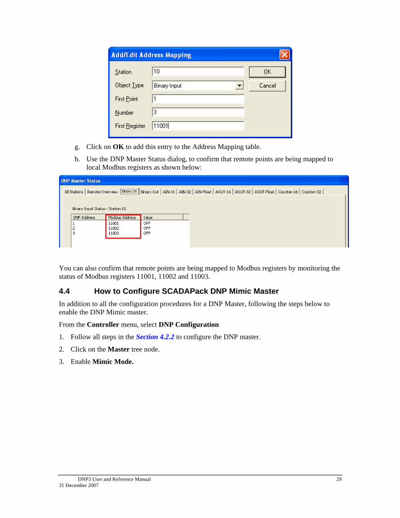
a. Click on the Add button to launch the Add/Edit Address Mapping dialog.
b. Enter 10 for Station.
c. Select Binary Input for Object Type.
d. Enter a value of 1 for First Point. This is the DNP Address of the first Binary Input point in Station 10.
e. Enter 3 for Number of points to map.
f. Enter 11001 for First Register (First Modbus Register) address. Note that Modbus address 11000 must exist the in your controller database.
CAUTION: In a practical setting, a DNP Master may have local I/O mapped also mapped to points within its DNP database. Ensure that you are not mapping outstation DNP points to local address being used by local I/O.
The completed dialog should look like this:
DNP3 User and Reference Manual 29 31 December 2007
g. Click on OK to add this entry to the Address Mapping table.
h. Use the DNP Master Status dialog, to confirm that remote points are being mapped to local Modbus registers as shown below:
You can also confirm that remote points are being mapped to Modbus registers by monitoring the status of Modbus registers 11001, 11002 and 11003.
4.4 How to Configure SCADAPack DNP Mimic Master
In addition to all the configuration procedures for a DNP Master, following the steps below to enable the DNP Mimic master.
From the Controller menu, select DNP Configuration
1. Follow all steps in the Section 4.2.2 to configure the DNP master.
2. Click on the Master tree node.
3. Enable Mimic Mode.

DNP3 User and Reference Manual 30 31 December 2007
5 SCADAPack DNP Router All SCADAPack controllers can be configured as a DNP Router. A unique characteristic of a SCADAPack DNP router is the ability to:
Route (or forward) DNP messages not destined to this station, using rules defined within a routing table.
Otherwise, a SCADAPack controller not configured for DNP routing will simply discard a message whose DNP destination address does not match that of the controller.
A DNP router is typically used when a direct communication link between the DNP master and outstation cannot be established, typically due to different physical layers on the two network segments. For instance, the physical network between the DNP SCADA Host and the router could be an Ethernet connection, while the physical layer between the router and all outstations could be a multi-drop serial RS-485 or even an RS-232 radio connection. Given that messages are routed directly from the DNP SCADA Host to the outstations, bandwidth limitations are dictated by the speed of the serial multi-drop connection. On the contrary, there is no bandwidth limitation within a DNP Mimic architecture, as the Mimic Master immediately responds to the DNP SCADA Host on behalf of the targeted outstation. Of course, the side effect of the DNP Mimic architecture is that polled data obtained by the DNP SCADA Host may not be very current. In either case, careful design considerations based on these tradeoffs should be exercised. See Chapter 6, for some ideas on design considerations.
As mentioned above, the SCADA Host has only one connection to a SCADAPack DNP Router. All target outstations of the SCADA Host are connected down stream of the DNP Router as illustrated in the figure below.
DNP SCADA Host SCADAPackDNP Router
SCADAPackDNP Outstation B
SCADAPack DNP Outstation C
Ethernet Multi-drop Serial RS-485 or RS-232 data radio
Figure 5-1: SCADAPack DNP Router and multi-dropped DNP Outstations
In the above configuration the SCADAPack DNP Router (Outstation A above) manages all the communication with the outstations. The SCADAPack DNP router receives messages from the SCADA Host for each outstation and route or forwards the messages to the outstations, based on routing rules established with the DNP Routing table.
DNP Messages are routed based on the following logic:
if (a message is received which needs to be retransmitted to someone else)
if (the message target is configured in our routing table)
if (the destination port is different from the incoming port)
or (routing is enabled on the incoming port)
then retransmit the message

DNP3 User and Reference Manual 31 31 December 2007
Change event data in the form of unsolicited responses from the outstations are routed directly to the DNP SCADA Host, by the SCADAPack DNP router.
A DNP Router is different from a Mimic in that a router forwards all messages are directly to the outstations, whereas the mimic responds to some messages on behalf of the outstations. Therefore, both operation modes have the advantage of delegating the task of DNP Routing of multiple outstations to this intermediate unit. The SCADAPack DNP router handles all communications paths to outstations, including such tasks as dial-up radio communication. In contrast to Mimic mode, however, the SCADA Host system still has to handle the long delays and high error rates that may be present on the communications links to the outstations.
Note: Mimic Master and Routing are incompatible modes that should never be used together.
5.1 How to Configure a SCADAPack DNP Router
In this exercise, we will configure a SCADAPack 32 controller to route DNP messages received from DNP Master 32001 on its Ethernet port, out through com2. This message is destined for outstation 20. .This exercise assumes a valid Ethernet connection between your PC or laptop and the SCADAPack 32.
After this exercise, you should be able to:
Configure DNP/TCP on an Ethernet port
Configure a SCADAPack DNP Router to route messages from a SCADA DNP Host to an outstation.
5.1.1 Tasks to Complete
1. Enable the DNP protocol communication on the communication interfaces involved in routing.
2. Enable routing on the communication interface.
3. Setup the forward and return entries in the DNP routing table.
5.1.2 Configuration Steps
1. From the Controller menu, click on Serial Ports.
2. In the Controller Serial Ports dialog, set the Protocol on COM2 to DNP.
3. In the Controller Serial Ports dialog, Enable Routing.
4. The completed dialog should look like this:

DNP3 User and Reference Manual 32 31 December 2007
5. Click on OK to close this dialog and save your settings.
6. From the Controller menu, click on IP Configuration.
7. Select the DNP/TCP tree node from the Controller IP Configuration dialog.
8. Enable the protocol and leave all other settings at default values.
Note: This exercise assumes that you have a valid IP Address, Subnet Mask and Default Gateway properly configured.
9. The completed dialog would look like this:

DNP3 User and Reference Manual 33 31 December 2007
TIP: In this configuration, the SCADAPack DNP Router is acting as a DNP Server on the Ethernet port. The Server Idle Timeout parameter will be used to determine how long this connection will be kept open from time of last communication activity. For a Server Idle Timeout default value of 4 minutes, and an Application Layer Timeout default value of 5 minutes, there is the possibility that the IP port will be closed, if the router is experiencing communication problems with the outstations. In this case, it is a good idea to increase the Server Idle Timeout to at least 2x the DNP configuration Application Layer Timeout. Or, simply reduce the Application Layer timeout to a value less than 2x the Server Idle Timeout.
10. From the DNP Configuration panel, select the Routing tree node.
e. Click on the Add button to begin a new routing table entry.
f. From the Add/Edit Route dialog,
Add the route to Station 20:
i. Enter 20 for the Station.
ii. Set the Port to COM2.
iii. Leave default values for all other parameters.
iv. Click on OK to add this entry to the routing table and return to the Routing dialog.
Add the Return route from Station 20:
i. Enter 32001 for the Station.
ii. Set the Port to DNP in TCP.
iii. Enter the IP Address of your DNP Master. In this case, the IP Address of my PC running a DNP SCADA Host software is 10.10.10.141.
iv. Leave default values for all other parameters.
v. The completed dialog should look like this:

DNP3 User and Reference Manual 34 31 December 2007
vi. Click on OK to add this entry to the routing table and return to the Routing dialog.
vii. The completed routing table should look like this:
Note: For proper operation of the router, there must be two routing entries in the routing table for each outstation; An entry specifying how the communication path from this router to the outstation and another communication path from the router to the SCADA DNP Master.
DNP3 User and Reference Manual 35 31 December 2007
6 Design Considerations The strength of DNP lies in its ability to offer time-stamped data, scheduled polling of data from multiple outstations and time synchronization, event data buffering and reporting by exception.
DNP was originally design to be used over a serial point-to-point (RS-232) link. As such, the protocol implements certain measures against data corruption and data loss in its Application and Data Link layers. Such measures include timeouts, retries, and checksums.
These data recovery mechanisms provided by the protocol, can be counter productive when not properly configured over an underlying communication medium, such as Ethernet, that already provides robust measures. In almost all of such cases, the recovery mechanisms offered by DNP need to be turned off. Such considerations together with good engineering judgment, therefore, must be practiced before one embarks on the design of a large DNP network.
This chapter outlines special considerations of the DNP protocol and implications within the SCADAPack DNP driver that should be considered when designing large networks. We also list common malpractices and a list of Frequently Asked Questions (FAQs) that arise during the course of network design.
6.1 Considerations of DNP3 Protocol and SCADAPack DNP Driver
To ensure consistent network performance, even under worse case scenarios, the following DNP specification rules should be considered when designing a DNP network using SCADAPack as the main nodes.
6.1.1 Unsolicited Messages always request for a Confirmation
An outstation will always request for an Application Layer confirmation when it sends an unsolicited message, even if the Application Layer confirmation field is not enabled. If no response is received within an Application Layer timeout, the outstation will retry the message a number of times as determined by the Application Layer Retry parameter.
6.1.2 Master shall never request for Application Layer Confirmation
A Master request is always accompanied by a response message from an outstation. Hence, the Application Layer confirmation on the master RTU should never be enabled.
6.1.3 DNP Write Messages always request for a Confirmation
As implemented in the SCADAPack DNP driver, a DNP Write request (FC 02) requires an Application Layer response from the outstation. If an acknowledgement is not received within the configured Application Layer timeout interval, the message is retried a number of times as determined by the Application Layer retry parameter.
6.1.4 Only one DNP3 transaction can be pending at a time
A SCADAPack DNP station will not initiate or process another DNP transaction, as long as one is outstanding. Thus, once a SCADAPack has initiated a DNP transaction, all subsequent DNP3 messages received but not related to the original transaction are buffered.

DNP3 User and Reference Manual 36 31 December 2007
6.1.5 SCADAPack controllers buffer 3 DNP messages
A SCADAPack serial port receive buffer can hold a maximum of 3 DNP messages or Data Link frames. If an additional DNP message is received when the buffer is full, the oldest message in the buffer is replaced with the newest one.
6.1.6 Output points in DNP Address Mapping issue DNP Write
Digital and analog output points contained within the DNP Address Mapping of a SCADAPack controller automatically issue DNP Write messages when their value or state changes.
6.2 Typical Configuration Malpractices and Recommendations
DNP is a capable protocol that effectively transfers some of the system engineering effort from designing a sophisticated logic program, to configuring and tuning the system using parameters. However, DNP does not eliminate the need to properly evaluate and engineer the communication media to support the performance expectations of the system, especially under worse case scenarios.
DNP networks can be designed around polling or report-by-exception. In a polling environment, each master request can be viewed as an invitation for an outstation device to transmit data on the shared communications medium. The master controls which device can transmit, thereby preventing collisions from occurring, as the timing of responses is predictable under all situations. In addition, masters can ask again if a response is not received, thus providing an opportunity for the outstation to re-send lost data. Using this strategy, a master effectively manages media access thereby preventing contention with those outstations unexpectedly transmitting on their own.
DNP networks can also be designed around unsolicited communications. In this case, the outstations transmit events to the master as they occur. When using this strategy, the communications media must be evaluated carefully in regards to the need for collision detection and prevention, if consistent network performance is to be expected.
Given that typical systems are designed using a combination of both strategies, is a good idea to start by configuring the network for poll mode, as it can be easily tuned to cater for unsolicited messaging, when system characteristics under worst case conditions become known. As with any communications system, the designer should pay careful attention to bandwidth allocation and management for a successful system implementation.
Below are several requirements of DNP system architecture that require careful engineering judgment.
1. Multiple high priority unsolicited messages configured in outstation.
2. System with multiple outstations, each containing numerous Class 1 events, configured with a Class 1 Hold Count of 1.
3. Relying on unsolicited messaging to get event data to master. System not designed around master polling for events.
4. Multiple masters with poor communication link.
5. Insufficient use of Deadband and debounce to curb event generation.
6. Master RTU has Application Layer confirmation enabled.
7. Enabling both the Application and Data Link Layer confirmations.
8. Setting very high Application Layer timeout values over high speed networks.

DNP3 User and Reference Manual 37 31 December 2007
9. DNP Address mapping contains multiple analog and digital output points that change rapidly.
The aforementioned statements and recommendations are provided below. Note that these recommendations are to ensure, consistent performance under worse case situations, and are based on the special considerations provided in the previous section.
6.2.1 Multiple High Priority Unsolicited Messages
A common configuration malpractice is to enable numerous high priority events objects within an outstation, and configure the outstation to trigger an unsolicited message to the master each time a new event occurs. In a SCADAPack controller, this is accomplished by configuring numerous Class 1 event objects, and enabling Class 1 Unsolicited Responses (Messaging) with a Hold Count or Hold Time of 1.
A Hold Count of 1 and Hold Time of 60 seconds specified for Class 1 events, imply that the controller will immediately trigger an unsolicited event as one occurs. If this outstation and others have a multitude of Class 1 event objects, visualize worse case scenario as a burst of messages being transmitted to the master at the same time. Given that a SCADAPack serial port buffer can only handle three DNP Data Link frames at any given time, some messages might get lost, especially if the master is required to immediately retransmit this message to some other node in return.
Such a system is designed around unsolicited messaging and is, therefore, far more susceptible to network collisions if proper management of bandwidth it not exercised. Given that a SCADAPack controller can only process one DNP transaction at a time, there is also a good chance that the serial port receive buffer will overflow, adding to the cost of lost messages.
Recommendations:
In general, bandwidth is used more efficiently in a large DNP system if the master is designed to poll for event data more frequently and static data less regularly.
Recommended practice is also to reserve unsolicited messaging for a small number of critical data. If possible, it may be best to ensure that no more than 3 messages are sent to the master at exactly the same time, under worse case scenario, as some event data may be lost if the master is currently busy processing another transaction, unless random retry intervals are put in place.
If unsolicited messaging is the predominant data transfer method, an approach to manage network usage, could be to configure a group of three or less outstations with a Hold Time that is unique within the group.
The table below shows an example configuration for Hold Time and Hold Counts for Class 1 events across six outstations.
Table 6-1: Hold Time and Hold Count Setup in for Six DNP Outstations
DNP Outstation Address
Hold Time (seconds)
Hold Count
11 1 100
12 1 100
13 1 100
14 2 100
15 2 100

DNP3 User and Reference Manual 38 31 December 2007
DNP Outstation Address
Hold Time (seconds)
Hold Count
16 2 100
6.2.2 Master not polling frequently causing event buffer overflows
An outstation does not discard the events within its buffer until all its configured masters have acknowledged receipt of these events. This means that an outstation event buffer may eventually fill up and overflow leading to loss of events. Buffer overflows typically indicate a poorly configured system.
When the system is designed around unsolicited messaging, there is a good likelihood of media contention causing buffer overflows. On the contrary, if the system is designed around frequent master poll for event data, there will be fewer chances of buffers overflowing causing loss of event data.
As stated earlier, immediate reporting of events using unsolicited messaging should be reserved for those critical, yet absolutely rare occurring events. This is because unsoliciting these messages back to the master will be reliable only if there is a substantial amount of unused bandwidth on the communication media. A good rule of thumb is to have 50% or more of unused bandwidth available, evenly distributed over a time frame.
Recommendation: Design the system around frequent master poll of class events and less regular integrity polls. Reserve unsolicited messaging for infrequent high priority events. If network traffic is predominated by unsolicited messaging, allocate 50% or more unused bandwidth as quiet time.
6.2.3 Outstation reports to Multiple Masters with Poor Comms
A poor communication link to one of an outstation’s multiple masters will prevent the outstation’s event buffer to be emptied, as events cannot be reported to the master. This could lead to buffer overflow situations and loss of event data.
Recommendation: Ensure that the communication path to all masters of an outstation is robust.
6.2.4 Insufficient Use of Input Deadband or Debounce
Event generation on a DNP analog input is controlled by a Deadband parameter. On a digital input, event generation is controlled by a debounce parameter. Default settings of zero for these parameters are typically overly aggressive and may lead to events being generated due to noise.
Recommendation: Set the analog Deadband and debounce parameters appropriately to non-zero values.
6.2.5 Master Confirmation and Retries
Application or Data Link Layer confirmations should never be enabled on a master as:

DNP3 User and Reference Manual 39 31 December 2007
1. Master requests typically will fit within a single Application Layer fragment hence there is need for Data Link Layer confirmations.
2. Master request typically require a response, hence no need for Application Layer confirmations.
Thus, enabling the Application Layer Confirmation on a DNP master is obsolete practice and may instead degrade system performance.
Recommendation: Disable the Application Layer Confirmation in a master SCADAPack controller. Typical retry values for Application Layer retries lie between 1 and 3. Lengthy retries may instead burden the communication medium
6.2.6 Outstation Confirmations and Retries
Confirmations on an outstation serve two useful purposes:
1. Ensure that a master received unsolicited responses from the outstation.
2. To ensure that a master correctly received responses to its request
Unsolicited messages will always request for an Application Layer confirmation, whether or not the Application Layer Confirmation is enabled on the outstation. If network traffic is predominantly unsolicited messaging, the Application Layer confirmation does not need to be enabled.
When the master is configured, as recommended, to frequently poll the outstation for event data using read request, while imposing a limit on the number of events the outstation should include in its response, the outstation still needs to know if the master received its replies so that it can:
Remove these events from its buffer
Know what to transmit next.
To cater for confirmations to read responses, Application Layer Confirmation in the outstation typically needs to be enabled.
The Data Link Layer breaks down Application Layer fragments into smaller frames. Smaller packet sizes reduce bit error in noisy environments. While it is better to accept the overhead of confirming each Data Link Layer frame of a multi-frame message, and re-transmit corrupted frames, than to re-send an entire Application Layer fragment, a viable alternative is to reduce the Application Layer fragment size and use only Application Layer confirmations. When fragments are reduced to the size of a Data Link Layer frame, the overhead of Application Layer confirmations, and the probability of noise corrupting those confirmation messages, is nearly the same as for Data Link Layer confirmations.
Enabling the Data Link layer confirmation on the outstation, therefore, is not required when the communication medium is not reliable. For example, certain data radios, e.g. FreeWave 9000 MHz spread spectrum radios, implement a robust mechanism to ensure that a data packet make it to their desired destination; TCP/IP incorporates robust mechanisms to prevent data loss; a local serial link between stations is also very reliable. In these cases, it is not necessary to enable the Data Link Layer confirmations.
If, however, physical medium quality if below par, such as in the case of noisy radio networks, or a shaky PSTN connections, then one should enable the Data Link Layer confirmation only, or as mentioned earlier, reduce the Application Layer maximum fragment length below 249 bytes.

DNP3 User and Reference Manual 40 31 December 2007
If either the Application or Data Link Layer Confirmation is enabled, retries should be configured to a low non-zero value. Typical retry values lie between 1 and 3. Lengthy retries may instead burden the communication medium
Recommendation:
Application and Data Link Layer confirmations in an outstation can be set according to the following table:
Communication Medium Reliability
High
Low
Data Acquisition Configuration
master polls outstation frequently for event data (also limits number of events in read response)
Enable Application Layer Confirmation
Disable Data Link Layer Confirmation
Disable Application Layer Confirmation
Enable Data Link Layer Confirmation
master does not poll frequently enough and outstation generates lot of unsolicited messages
Enable Application Layer Confirmation
Disable Data Link Layer Confirmation
Disable Application Layer Confirmation
Enable Data Link Layer Confirmation
Regardless of the data acquisition strategy, if the Max Application Layer fragment is set to a values less than 249
Enable Application Layer Confirmation
Disable Data Link Layer Confirmation
Enable Application Layer Confirmation
Disable Data Link Layer Confirmation
Note: It is never required to enable BOTH the Application and Data Link Layer Confirmations.
6.2.7 Setting relatively large Application Layer timeouts
On a high speed link, such as Ethernet, configuring a high Application Layer timeout does not increase network reliability. Instead this reduces system performance, as there will be a significant portion of time within the timeout period, after which the IP transaction may have been terminated.
Typically, an Ethernet transaction is completed in the order of a millisecond and a DNP master SCADAPack controller, by default, closes its DNP TCP port within 10 seconds of no activity. A DNP SCADAPack controller acting as an outstation closes its port by default in about 4 minutes.
Under these default conditions, if the application layer timeout on a SCADAPack DNP master is set for 15 seconds, for instance, the port may have closed 10 seconds after last activity, but the application may still be waiting for a timeout.
If a message is somehow lost, and the timeout is set for 5 seconds, for instance, the application will still be waiting for a response even though the IP transaction has terminated. This results to wasted bandwidth.
Recommendation: When operating over high speed links, make Application Layer timeouts as small as possible.
6.2.8 DNP Address mapping contains multiple output points

DNP3 User and Reference Manual December 31, 2007
41
The DNP Address Mapping table allows local Modbus registers in the SCADAPack DNP master to be mapped to DNP points in an outstation. Each time an output register defined within the DNP Address Mapping table changes, a DNP Write message (FC 2) is immediately issued to update the corresponding DNP point in the outstation.
If numerous output registers that change frequently, are listed in the Address Mapping table, the network will be overburdened with a multitude of DNP Write messages.
Recommendation: Reserve Address Mapping only for mapping of outstation DNP data that needs to be used by the master Modbus database, or to segregate points from different outstations in the master. If numerous points are being mapped from the outstation to the master, the system is not designed properly. In this case, it may be worthwhile to consider transferring application logic from the master to the outstation.
6.3 Configuration FAQ
Complimentary commonly asked questions and answers are given below.
When configuring a routing entry in the DNP Routing table of a SCADAPack, one has to specify the Data Link Layer Timeout and Retries. Do these fields take precedence over the same fields found under the Data Link Layer configuration panel?
Yes.
In a master-outstation architecture, how do you recommend we setup time synchronization?
Recommended practice is to configure the master to initiate time synchronization to the outstations.
DNP3 provides 4 data classes; Class 0 (Static or None), Class 1, Class 2 and Class 3. How does I decide which class to assign any given I/O point?
In a SCADAPack controller, all configured DNP points by nature, are members of the Class 0 type. Class 0 data is the current value or state of a DNP point. So, when a master does a Class 0 poll to an outstation, the most current value or state of all DNP points within the database are returned.
Value or state changes on a point are captured as Class 1, Class 2 or Class 3 event data. Typically, highest priority events are assigned to Class 1 and the lowest priority event to Class 3.
What does Class of ‘None’ mean?
Class None is Class 0 or Static.
Why does this setting do: Enable Unsolicited Responses On Startup?
This setting enables unsolicited response (or unsolicited message) transmission, when power to an RTU is cycled or when its configuration is changed. In this case, the RTU does not have to wait for Function Code 20 or 0x14 (Enable Unsolicited Responses) from the master before is starts sending any collected events.
This field should be set to No, to allow a master control when an outstation is able to send unsolicited messages. Recommended practice is to allow a master to enable unsolicited message transmission on all outstations.
Why would I ever need to change the Application Layer Maximum Fragment Length?

DNP3 User and Reference Manual December 31, 2007
42
The Application Layer Maximum Fragment Length determines the maximum amount of memory that is reserved for each application layer fragment. The default is 2048 bytes on SCADAPack controllers although outstations must be prepared to receive fragments sizes of at least 249 bytes. When communicating with those devices with insufficient memory it is necessary to limit the maximum application layer fragment length to what the outstation can handle. In addition, limiting the application layer fragment size beyond 249 also reduces the maximum Data Link layer frame length.
Certain data radios may give better efficiency when transmitting data packets less than the maximum data link fragment size of 249 bytes. With these radios, it is necessary to reduce the application layer’s maximum fragment size below 249 bytes as required by the radio.
Other types of data radios, such as FreeWave’s 900 MHz Spread Spectrum radios, provide configuration options to optimize efficiency by changing the maximum packet size. In this case, it is not necessary to reduce the application layer maximum fragment size.
In addition, when the communication medium is noisy, it is typically more efficient to transmit smaller packets than larger packets. In this case, setting small Application Layer fragments would force smaller data link frames, which is a better strategy in a noisy environment.
Caution: Limiting the application layer fragment size reduces the rate at which event data is retrieved from the buffers, thus increasing the possibility of event buffer overflows, if the event data is not being retrieved in a timely fashion. Reducing the maximum application layer fragment size, increases network traffic and also reduced data throughput as an Application Layer Confirmation is required for each fragment of a multi-fragment message.
Why would I ever want to ‘Limit that maximum number of events in a read response?”
This is another strategy that can be used to limit the Application Layer fragment of an outstations’ response message. This strategy could be used under noisy environments.
Also, this could be used to prevent an outstation with a large collection of event data to hold the communication media captive while transmitting all its events.
What behavior should we expect from a SCADAPack when the event logs are full?
When a new event is collected and the SCADAPack DNP event buffer is full, the oldest event is deleted and the newest event added into the buffer.
What is the main difference between SCADAPack DNP driver configuration modes?
DNP Master DNP Mimic Master Address Mapping
Router Outstation
Define DNP I/O points
Not necessary Not necessary Not necessary Not necessary
Yes
Enable Application Layer Confirmation
No No No No. Not necessary.
Should I Initiate Time synchronization?
Yes No. No. No. No.
Poll for Class DNP static and Class data?
Yes
Yes Yes No. No
Initiates No No No No Yes

DNP3 User and Reference Manual December 31, 2007
43
Unsolicited messages?
Router Messages not destined to this station?
No Some No Yes No
When best to use Master in a Point to Multipoint network
Data Concentrator with many outstations that will take a while to configure. When outstation data does not need to be available to logic in this node.
When remote DNP data is needed by local program
Strictly Repeater
Forms basic node in DNP network.

DNP3 User and Reference Manual December 31, 2007
44
7 DNP Configuration Menu Reference This section of the manual details the SCADAPack DNP3 driver configuration parameters. The DNP Configuration panel is accessed from the Controller | DNP Configuration menu from either TelePACE or ISaGRAF. Browse through this chapter to familiarize yourself with some key DNP3 concepts and their implementation in a SCADAPack controller.
When selected the DNP Settings window is opened, as shown below.
The DNP Settings window has a tree control on the left side of the window. The tree control appears differently depending on the controller type selected. The SCADAPack 350, SCADAPack 32 and SCADAPack 32P controllers support DNP master and include the bolded items in the following list. Other SCADAPack controllers do not support DNP master and do not include the bolded items. This tree control contains headings for:
Application Layer
Data Link Layer
Master
Master Poll

DNP3 User and Reference Manual December 31, 2007
45
Address Mapping
Routing
Binary Inputs
Binary Outputs
16-Bit Analog Inputs
32-Bit Analog Inputs
Short Floating Point Analog Inputs
16-Bit Analog Outputs
32-Bit Analog Outputs
Short Floating Point Analog Outputs
16-Bit Counter Inputs
32-Bit Counter Inputs
When a tree control is selected by clicking the mouse on a heading a property page is opened for the header selected. From the property page the DNP configuration parameters for the selected header is displayed.
As DNP objects are defined they are added as leaves to the object branch of the tree control. When an object is defined the object branch will display a collapse / expand control to the left of the branch.
The Allow Duplicate Modbus Addresses checkbox (in the bottom left corner) determines if the Modbus I/O database addresses assigned to the DNP data points must be unique. Check this box if you want to allow more than one point to use the same Modbus address.
Uncheck the box if you want to be warned about duplicate addresses. If an attempt is made to use a Modbus address that has already been used for another DNP point the following warning is displayed.
7.1 Application Layer Configuration
The Application Layer property page is selected for editing by clicking Application Layer in the tree control section of the DNP Settings window. When selected the Application Link Layer property page is active.

DNP3 User and Reference Manual December 31, 2007
46
Application Layer parameters are set in this property page. Each parameter is described in the following paragraphs.
The Communication section of the dialog contains the configurable application layer communication parameters.
When the Application Confirmation feature is enabled, the SCADAPack controller requests a confirmation from the master station for any data transmitted. When it is disabled, the controller does not request a confirmation from the master station and assumes that the master receives the data it sends successfully. However if the data includes event data (including unsolicited messages), the controller requests a confirmation from the master regardless of whether this feature is enabled or disabled. Valid selections for this parameter are:
Enabled
Disabled
The Maximum Fragment Length is maximum size of a single response fragment that the RTU will send. If the complete response message is too large to fit within a single fragment, then the SCADAPack controller will send the response in multiple fragments. Valid values are between 100 and 2048 bytes.

DNP3 User and Reference Manual December 31, 2007
47
This parameter is adjustable to allow for interoperability with simple DNP3 devices that require smaller application layer fragments. Devices with limited memory may restrict the application layer fragment size to as low as 249 bytes.
Note: The Maximum Fragment Length parameter applies to responses from read commands only. It does not affect unsolicited responses.
The Retries entry maximum number of times the application layer will retry sending a response or an unsolicited response to the master station. This does not include any retries performed by the data link layer. Valid values are between 0 and 255.
Note: Using application layer Confirmation and Retries is inherently more efficient than using data link layer Confirmation and Retries. Each fragment sent by the Application layer may require as many as 10 data link layer frames to be sent, each with its own confirmation message. The application layer is typically preferred for message confirmation for this reason.
The Application Timeout is the expected time duration (in milliseconds) that the master station's application layer requires to process and respond to a response from the SCADAPack controller. This SCADAPack controller uses this value in setting its time-out interval for master station responses. This value should be large enough to prevent response time-outs. The value must be kept small enough so as not to degrade system throughput. The value of this element is dependent on the master station. Valid values are between 100 and 60000 milliseconds.
The Time Synchronization section of the dialog defines when and how often the SCADAPack outstation prompts the master station to synchronize the SCADAPack controller time. Messages must be sent between the Master and Remote stations for Time Synchronization to work. Valid selections for this parameter are:
The None selection will cause the SCADAPack controller to never request Time Synchronization.
The At Start Up Only selection will cause the SCADAPack controller to request Time Synchronization at startup only.
The Interval selection will cause the SCADAPack controller to request Time Synchronization at startup and then every Interval minutes after receiving a time synchronization from the master. Valid entries for Interval are between 1 and 32767 minutes. The default value is 60 minutes.
Note: Time Synchronization may instead be initiated by the Master for each Outstation. This may be selected in the Add/Edit Master Poll dialog. It is not required to enable Time Synchronization at both the Master and the Outstation.
The Unsolicited Response section of the dialog defines which class objects are enabled or disabled from generating report by exception responses. Unsolicited responses are individually configured for Class 1, Class 2, and Class 3 data.
The Enable Unsolicited controls enables or disables the generation of unsolicited events for Class 1, Class 2 or Class 3 data. If unsolicited responses are disabled for a Class the controller never generates unsolicited events for that Class. If unsolicited responses are enabled the controller generates unsolicited events for that Class if its value or state exceeds a defined threshold. Valid selections are:
Enabled
DNP3 User and Reference Manual December 31, 2007
48
Disabled
Note that the controller does not transmit collected unsolicited messages (or responses) to a master, even after the Hold Time or Hold Count conditions have been met, unless its 'Enable Unsolicited Responses on Start Up' field is set to 'Yes' or the master triggers this transmission.
To configure a master to control unsolicited message transmission from a remote, see the Master Poll configuration panel.
The Hold Time parameter is used only when unsolicited responses are enabled for a Class. This parameter defines the maximum period (in seconds) the RTU will be allowed to hold its events before reporting them to the DNP master station. When the hold time has elapsed since the first event occurred, the RTU will report to the DNP master station all events accumulated up to then. This parameter is used in conjunction with the Hold Count parameter in customizing the unsolicited event reporting characteristics. The value used for the Hold Time depends on the frequency of event generation, topology and performance characteristics of the system. The valid values for this parameter are 0 - 65535. The default value is 60 seconds.
The Hold Count parameter is used only when unsolicited responses are enabled for a Class. This parameter defines the maximum number of events the RTU will be allowed to hold before reporting them to the DNP master station. When the hold count threshold is reached, the RTU will report to the master, all events accumulated up to that point. This parameter is used in conjunction with the Hold Time in customizing the unsolicited event reporting characteristics. To guarantee an unsolicited response is sent as soon as an event occurs, set the Hold Count parameter to 1. The valid values for this parameter are 1 - 65535. The default value is 10.
The Enable Unsolicited Responses on Start Up parameter enables or disables unsolicited responses on startup. This affects the default controller behaviour after a start-up or restart. Some hosts require devices to start up with unsolicited responses enabled. It should be noted this is non-conforming behaviour according to the DNP standard. Valid selections are:
Yes
No
The default selection is Yes.
The Send Initial Unsolicited Response on Startup parameter enables or disables Send Initial unsolicited responses on startup. This parameter controls whether an initial unsolicited response with null data is sent after a start-up or restart. Valid selections are:
Yes
No
The default selection is No.
The Resend unreported events after parameter enables or disables the retransmission of events after all attempts to report the events have failed.
Many communications networks experience occasional communications failures. In such networks, even when message retries are used, there is a chance that some messages will fail – meaning there is a chance some unsolicited messages will fail and change events will not be reported to the master station. The events remain in the outstation buffers until polled or additional events are generated.
DNP3 User and Reference Manual December 31, 2007
49
To address this issue, and ensure guaranteed delivery of high priority events, the Resend unreported events after parameter is added to the DNP configuration. This parameter controls a timer for retrying the transmission of unsolicited messages.
Whenever a DNP unsolicited message fails, including all its retries, then instead of just retiring the message and reporting it as a failed message, an unsolicited resend timer is initiated. After the configured time delay has passed, the unsolicited message will be sent again, including the configured retries. This process will be repeated continuously until the unsolicited message is successfully sent and acknowledged. In the case of multiple masters the unsolicited resend timer is uninitiated after the retries are expired for the last master in the polling list.
Note: SCADAPack firmware 2.44 (and later), SCADAPack 32 Firmware 1.92 (and later), SCADAPack 350/SCADASense firmware 1.25 (and later) and SOLARPack 410 firmware 1.32 (and Later) support this feature.
Valid values are 1 to 65535 seconds. The default value is 0 seconds. The control is unselected by default.
If Resend unreported events is not selected, the controller will not resend unreported events after all attempts fail, until polled or until additional events are generated and their reporting threshold is reached.
The Resend unreported events control can be selected even when no classes are enabled. This allows the feature to be used in a mimic controller that is being used to pass outstations events to a host.
The Dial Up section of the dialog defines modem parameters used when a dial up modem is used to communicate with stations that use dial up communication. The phone numbers for the stations are defined in the Routing table.
The Modem Initialization is the string that will be sent to the modem prior to each call. This is an ASCII null-terminated string. The maximum length of the string is 64 characters, including the null terminator.
The Attempts controls the maximum number of dial attempts that will be made to establish a Dial Up connection. The valid values for this parameter are 1 – 10. The default value is 2.
The Dial Type parameter controls whether tone or pulse dialing will be used for the call. Valid values are Tone dialing or Pulse dialing. The default value is Tone dialing.
The Connect Timeout controls the maximum time (in seconds) after initiating a dial sequence that the firmware will wait for a carrier signal before hanging up. The valid values for this parameter are 1 – 65535. The default value is 45.
The Inactivity Timeout controls the maximum time after message activity that a connection will be left open before hanging up. The valid values for this parameter are 1 – 65535 seconds. The default value is 45 seconds.
The Pause Time controls the delay time (in seconds) between dial events, to allow time for incoming calls. The valid values for this parameter are 1 – 65535. The default value is 10.
The Operate Timeout parameter specifies the timeout interval between a Select and Operate request from the Master. If after receiving a valid Select control output request from the master, the RTU does not receive the corresponding Operate request within this time-out interval, the control output request fails. The value of this parameter, expressed in seconds, is dependent on the master station, the data link and physical layer. Valid values are 1 to 6500 seconds. The

DNP3 User and Reference Manual December 31, 2007
50
default value is 15 seconds. The Master must have the Select/Operate functionally in order to use this feature.
The Report only Level 2 Compliant Objects in Class Polls parameter affects how Short Float Analog Input, Short Float Analog Output, and 32-bit Analog Output objects are reported. These objects are converted to 32-bit Analog Input and 16-bit Analog Output objects when this parameter is selected. Valid selections are:
Yes
No
The default selection is No.
The Limit Maximum Events in Read Response parameter allows limiting the number of events in a read response. Select the checkbox to enable the limit. Valid values are 1 to 65535. The default value is disabled.
Note: The Maximum Events parameter applies to responses from read commands only. It does not affect unsolicited responses.
The Allow Duplicate Modbus Addresses checkbox determines if the Modbus I/O database addresses assigned to the DNP data points must be unique. Check this box if you want to allow more than one point to use the same Modbus address.
Click the OK button to accept the configuration changes and close the DNP Settings dialog.
Click the Cancel button to close the dialog without saving any changes.
7.2 Data Link Layer Configuration
The Data Link Layer property page is selected for editing by clicking Data Link Layer in the tree control section of the DNP Settings window. When selected the Data Link Layer property page is active.

DNP3 User and Reference Manual December 31, 2007
51
Data Link Layer parameters are set in this property page. Each parameter is described in the following paragraphs.
The Master Station Addresses list box contains a list of Master station addresses that the SCADAPack controller will respond to. The default list contains one master address of 100. This address may be edited, or changed, and up to 8 master stations may be added to the list. Valid entries for Master Station Addresses are 0 to 65519.
When a master station polls for event data, the controller will respond with any events that have not yet been reported to that master station.
When an unsolicited response becomes due, it will be sent to each configured master station in turn. A complete unsolicited response message transaction, including retries, will be sent to the first configured master station. When this transaction has finished, a complete unsolicited response message transaction including retries will be sent to the next configured master station, and so on for all the configured master stations.
Change events will be retained in the event buffer until they have been successfully reported to all configured master stations.
Select the Add button to enter a new address to the Master Station Address list. Selecting the Add button opens the Add Master Station Address dialog. Up to 8 entries can be added to the table. An error message is displayed if the table is full.

DNP3 User and Reference Manual December 31, 2007
52
Select the Edit button to edit address in the Master Station Address list. Selecting the Edit button opens the Edit Master Station Address dialog. The button is disabled if there are no entries in the list.
The Master Station Address edit box specifies the Master Station Address. Enter any valid Station address from 0 to 65519.
The OK button adds the Master Station Address to the list and closes the dialog. An error is displayed if the Master Station Address is invalid, if the address is already in the list, or if the address conflicts with the RTU station address.
The Cancel button closes the dialog without making any changes.
The RTU Station Address parameter specifies the address of this RTU. It is the source address used by this DNP driver when communicating with a master station. Each DNP station in a network must have a unique address, including the Master station. Valid entries for RTU Station Address are 0 to 65519.
The Data Link Confirmation parameter specifies whether or not the RTU requests the underlying data link transmitting its response to use a high quality service, which generally means that the data link requires the receiving data link to confirm receipt of all messages.
The Retries parameter specifies the maximum number of times the data link layer will retry sending a message to the master station. This parameter is only used when responding to a request from a Master station, when there is no corresponding entry in the Routing dialog for that station. This is independent of the application layer retries. The valid values for this parameter are 0 - 255. Setting the value to 0 disables sending retries.
Note: Using data link layer Confirmation and Retries is inherently less efficient than application layer Confirmation and Retries. Each fragment sent by the Application layer may require as many as 10 data link layer frames to be sent, each with its own confirmation message. The data link layer is typically not used for message confirmation for this reason.
The Data Link Timeout parameter specifies the expected time duration that the master station's data link layer requires to process and respond to a message from the RTUs data link layer. It is used by the RTU in setting its time-out interval for master station responses. This value should be large enough to prevent response time-outs. The value must be kept small enough so as not to degrade system throughput. The value of this element is dependent on the master station. It is expressed in milliseconds. Valid values are 10 to 60000 milliseconds. The default value is 500 milliseconds.
Click the OK button to accept the configuration changes and close the DNP Settings dialog.
Click the Cancel button to close the dialog without saving any changes.
Click the Delete button to remove the selected rows from the list. This button is disabled if there are no entries in the list.

DNP3 User and Reference Manual December 31, 2007
53
The Allow Duplicate Modbus Addresses checkbox determines if the Modbus I/O database addresses assigned to the DNP data points must be unique. Check this box if you want to allow more than one point to use the same Modbus address.
7.3 Master
The Master property page is selected for editing by clicking Master in the tree control section of the DNP Settings window. This selection is only visible if the controller type is SCADAPack 350, SCADAPack 32 or SCADAPack 32P. These controllers support DNP Master. When selected the Master Application Link Layer property page is active.
Master parameters are set in this property page. Each parameter is described in the following paragraphs.
The Mimic Mode parameter specifies the DNP Mimic Mode. The valid selections are Enable or Disable. When DNP Mimic Mode is enabled the controller will intercept DNP messages destined for a remote DNP station address, and will respond directly, as though the controller were the designated target. For read commands, the controller will respond with data from its Remote DNP Objects corresponding with the intended target address. For write commands, the controller will write data into its Remote DNP Objects, and issue a direct response to acknowledge the command. It will then issue a new command to write the data to the designated target. See Section 4.1.1-SCADAPack DNP Mimic Master section for an explanation of the concept around Mimic Mode. The default selection is Disabled.

DNP3 User and Reference Manual December 31, 2007
54
The Base Poll Interval parameter is the base interval (in seconds) for polling slave devices. The poll rates and issuing time synchronisation will be configured in multiples of the base poll interval. The slave devices with the same poll rates will be polled in the order they appear in the poll table. The valid values for this parameter are 1 to 65535. The default value is 10 seconds.
7.4 Master Poll
The Master Poll property page is selected for editing by clicking Master Poll in the tree control section of the DNP Settings window. This selection is only visible if the controller type is a SCADAPack 350, SCADAPack 32 or SCADAPack 32P. These controllers support DNP Master. When selected the Master Poll property page is active and button Copy is renamed to Edit.
The Master Poll displays slave devices to be polled by this master station as a row, with column headings, in the table. The table may have up to 1000 entries. A vertical scroll bar is used if the list exceeds the window size.
Note: All slave devices in the Master Poll table need to be added to the Routing table.
The Station column displays the address of the DNP slave device to be polled. Each entry in the table should have unique DNP Station Address.
The Class 0 Rate column displays the rate of polling for Class 0 data, as a multiple of the base poll interval.
The Class 1 Rate column displays the rate of polling for Class 1 data, as a multiple of the base poll interval.

DNP3 User and Reference Manual December 31, 2007
55
The Class 2 Rate column displays the rate of polling for Class 2 data, as a multiple of the base poll interval.
The Class 3 Rate column displays the rate of polling for Class 3 data, as a multiple of the base poll interval.
The OK button saves the table data and closes the DNP Settings dialog.
The Cancel button closes the dialog without saving changes.
Select the Add button to enter a new row in the Master Poll. Selecting the Add button opens the Add/Edit Master Poll dialog.
Select the Edit button to modify the selected row in the Master Poll. Selecting the Edit button opens the Add/Edit Master Poll dialog containing the data from the selected row. This button is disabled if more than one row is selected or if there are no entries in the table.
The Delete button removes the selected rows from the table. This button is disabled if there are no entries in the table.
The Allow Duplicate Modbus Addresses checkbox determines if the Modbus I/O database addresses assigned to the DNP data points must be unique. Check this box if you want to allow more than one point to use the same Modbus address.
Click on the column headings to sort the data. Clicking once sorts the data in ascending order. Clicking again sorts the data in descending order.
7.4.1 Add/Edit Master Poll Dialog
This dialog is used to edit an entry or add a new entry in the Master Poll.

DNP3 User and Reference Manual December 31, 2007
56
The Station edit control displays the address of the DNP slave device to be polled. Valid values are 0 to 65519.
The Class 0 Polling section of the dialog specifies the type and rate of polling for Class 0 data.
The None selection disables class 0 polling for the slave station. This is the default selection.
The At Start Up Only selection will cause the master to poll the slave station at startup only.
The Interval selection will cause the master to poll the slave station at startup and then every Interval of the base poll interval. For example if the base poll interval is 60 seconds and the Interval parameter is set to 60 then the master will poll the slave station every hour. Valid values are 1 to 32767. The default value is 60.
The Poll Offset parameter is used to distribute the load on the communication network. The Poll Offset is entered in multiples of the base poll interval. Valid values for this parameter are 0 to the Poll Interval value minus 1. Any non-zero value delays the start of polling for the specified objects by that amount. The default value is 0. This control is disabled when None is selected, and enabled otherwise. For an example of using the Poll Offset parameter see the Poll Offset Example at the end of this section.
The Class 1 Polling section of the dialog specifies the type and rate of polling for Class 1 data.
The None selection disables class 1 polling for the slave station. This is the default selection.
The At Start Up Only selection will cause the master to poll the slave station at startup only.
The Interval selection will cause the master to poll the slave station at startup and then every Interval of the base poll interval. For example if the base poll interval is 60 seconds and the Interval parameter is set to 60 then the master will poll the slave station every hour. Valid values are 1 to 32767. The default value is 60.

DNP3 User and Reference Manual December 31, 2007
57
The Poll Offset parameter is used to distribute the load on the communication network. The Poll Offset is entered in multiples of the base poll interval. Valid values for this parameter are 0 to the Poll Interval value minus 1. Any non-zero value delays the start of polling for the specified objects by that amount. The default value is 0. This control is disabled when None is selected, and enabled otherwise. For an example of using the Poll Offset parameter see the Poll Offset Example at the end of this section.
Limit Maximum Events allows limiting the number of events in poll responses for Class 1/2/3 data. The checkbox is not checked by default, meaning there is no limit on the number of events. Select the checkbox to specify a limit. The valid values for this parameter are 1 to 65535. The default value is 65535. This control is disabled when None is selected, and enabled otherwise. The Maximum Events parameter can be used to manage communication load on a system.
Consider the example of a master polling some data logging remotes, and the case where one of the remotes has been offline for a long time. The remote will have built up a large number of buffered events. If the master polled it for all events, the reply might take a long time, and cause an unwanted delay in the master's polling cycle. However if the master limits the number of events returned, the reply message duration will be more deterministic and the master can ensure its poll loop timing is maintained. In this case, the event retrieval from the data logger will be distributed over a number of poll cycles.
The Class 2 Polling section of the dialog specifies the type and rate of polling for Class 2 data.
The None selection disables class 1 polling for the slave station. This is the default selection.
The At Start Up Only selection will cause the master to poll the slave station at startup only.
The Interval selection will cause the master to poll the slave station at startup and then every Interval of the base poll interval. For example if the base poll interval is 60 seconds and the Interval parameter is set to 60 then the master will poll the slave station every hour. Valid values are 1 to 32767. The default value is 60.
The Poll Offset parameter is used to distribute the load on the communication network. The Poll Offset is entered in multiples of the base poll interval. Valid values for this parameter are 0 to the Poll Interval value minus 1. Any non-zero value delays the start of polling for the specified objects by that amount. The default value is 0. This control is disabled when None is selected, and enabled otherwise. For an example of using the Poll Offset parameter see the Poll Offset Example at the end of this section.
Limit Maximum Events allows limiting the number of events in poll responses for Class 1/2/3 data. The checkbox is not checked by default, meaning there is no limit on the number of events. Select the checkbox to specify a limit. The valid values for this parameter are 1 to 65535. The default value is 65535. This control is disabled when None is selected, and enabled otherwise.
The Maximum Events parameter can be used to manage communication load on a system. Consider the example of a master polling some data logging remotes, and the case where one of the remotes has been offline for a long time. The remote will have built up a large number of buffered events. If the master polled it for all events, the reply might take a long time, and cause an unwanted delay in the master's polling cycle. However if the master limits the number of events returned, the reply message duration will be more deterministic and the master can ensure its poll loop timing is maintained. In this case, the event retrieval from the data logger will be distributed over a number of poll cycles.
The Class 3 Polling section of the dialog specifies the type and rate of polling for Class 3 data.

DNP3 User and Reference Manual December 31, 2007
58
The None selection disables class 1 polling for the slave station. This is the default selection.
The At Start Up Only selection will cause the master to poll the slave station at startup only.
The Interval selection will cause the master to poll the slave station at startup and then every Interval of the base poll interval. For example if the base poll interval is 60 seconds and the Interval parameter is set to 60 then the master will poll the slave station every hour. Valid values are 1 to 32767. The default value is 60.
The Poll Offset parameter is used to distribute the load on the communication network. The Poll Offset is entered in multiples of the base poll interval. Valid values for this parameter are 0 to the Poll Interval value minus 1. Any non-zero value delays the start of polling for the specified objects by that amount. The default value is 0. This control is disabled when None is selected, and enabled otherwise. For an example of using the Poll Offset parameter see the Poll Offset Example at the end of this section.
Limit Maximum Events allows limiting the number of events in poll responses for Class 1/2/3 data. The checkbox is not checked by default, meaning there is no limit on the number of events. Select the checkbox to specify a limit. The valid values for this parameter are 1 to 65535. The default value is 65535. This control is disabled when None is selected, and enabled otherwise. The Maximum Events parameter can be used to manage communication load on a system. Consider the example of a master polling some data logging remotes, and the case where one of the remotes has been offline for a long time. The remote will have built up a large number of buffered events. If the master polled it for all events, the reply might take a long time, and cause an unwanted delay in the master's polling cycle. However if the master limits the number of events returned, the reply message duration will be more deterministic and the master can ensure its poll loop timing is maintained. In this case, the event retrieval from the data logger will be distributed over a number of poll cycles.
The Time Synchronization Rate section of the dialog specifies the rate of issuing a time synchronization to this device, as a multiple of the base poll interval. Valid selections for this parameter are:
The None selection will disable issuing a time sync to this device. This is the default selection.
The At Start Up Only selection will cause issuing a time synchronization at startup only.
The Interval selection will cause the RTU to issue a time synchronization at startup and then every Interval of the base poll interval seconds. Valid entries for Interval are between 1 and 32767 the base poll interval seconds. The default value is 60.
The Unsolicited Responses section is used in conjunction with the Enable Unsolicited Responses on Start Up parameter on the Application Layer page. Certain non-SCADAPack slave devices are designed to start with their Enable Unsolicited Responses on Start Up parameter set to No. Selecting Enabled for any class causes the master to (after it detects the slave come online) send a command allowing the slave to begin sending Unsolicited Responses of that class.
With SCADAPack slaves the Enable Unsolicited Responses on Start Up parameter may be set to Yes, and the Accept Class parameters may be left at Disabled.
The Accept Class 1 selection displays the enable/disable status of unsolicited responses from the slave device for Class 1 events. The default selection is disabled.

DNP3 User and Reference Manual December 31, 2007
59
The Accept Class 2 selection displays the enable/disable status of unsolicited responses from the slave device for Class 1 events. The default selection is disabled.
The Accept Class 3 selection displays the enable/disable status of unsolicited responses from the slave device for Class 1 events. The default selection is disabled.
The Save IIN Flags checkbox enables storing the IIN (Internal Indications) flags from the slave station in a Modbus database register. When this parameter is checked the IIN flags are saved to the entered Modbus register address. Valid entries are Modbus register addresses 30001 to 39999 and 40001 to 49999. The default value is 0.
The IIN flags are set by the slave to indicate the events in the following table. The events are bit mapped to the Modbus register. All bits except Device Restarted and Time Synchronization required are cleared when the slave station receives any poll or read data command. The master will write to bits 5 and 11 depending on the local conditions in the master.
Bit Description
0 last received message was a broadcast message
1 Class 1 data available
2 Class 2 data available
3 Class 3 data available
4 Time Synchronization required
5 not used (returns 0)
6 Device trouble Indicates memory allocation error in the slave, or For master in mimic mode indicates communication failure with the slave device.
7 Device restarted (set on a power cycle)
8 Function Code not implemented
9 Requested object unknown or there were errors in the application data
10 Parameters out of range
11 Event buffer overflowed Indicates event buffer overflow in the slave or master. The slave will set this bit if the event buffer in the slave is overflowed. The master will set this bit if the event buffer in the master has overflowed with events read from the slave. Ensure the event buffer size, in the master and slave, is set to a value that will ensure the buffer does not overflow and events are lost.
12 not used (returns 0)
13 not used (returns 0)
14 not used (returns 0)
15 not used (returns 0)
The OK button checks the data for this table entry. If the data is valid the dialog is closed. If the table data entered is invalid, an error message is displayed and the dialog remains open. The table entry is invalid if any of the fields is out of range. The data is also invalid if it conflicts with another entry in the table. Such conflict occurs when the station number is not unique. The ordering of items in this table is important.
The Cancel button closes the dialog without saving changes.
7.4.2 Poll Offset Example

DNP3 User and Reference Manual December 31, 2007
60
The Poll Offset parameter enhances the control over timing of master poll messages, by allowing master poll messages to be staggered.
For example, a master station may have 10 slaves to poll, and must poll them every hour. If these are included in the poll table without any poll offset, they will all be polled in quick succession on the hour – resulting in a large burst of communication activity once per hour. On some types of communications networks (particularly radio) it is desirable to distribute communication load more evenly, to minimize the chance of collisions and to avoid the possibility of consuming bandwidth continuously for an extended period of time.
The poll offset parameter enables you to distribute the communication load evenly. In the above example, it is possible to stagger the master polls so slave stations are polled at 6-minute intervals. To do this, set the base poll interval to 10 seconds, and for each slave station set the poll rate and poll offset parameters as follows:
Base Poll (seconds) Poll Rate (seconds) Poll Offset (seconds)
10 360 0 10 360 36 10 360 72 10 360 108 10 360 144 10 360 180 10 360 216 10 360 252 10 360 288 10 360 324
7.5 Address Mapping
The Address Mapping property page is selected for editing by clicking Address Mapping in the tree control section of the DNP Settings window. This selection is only visible if the controller type is a SCADAPack 350, SCADAPack 32 or SCADAPack 32P. These controllers support DNP Master.

DNP3 User and Reference Manual December 31, 2007
61
The Address Mapping contains a set of mapping rules, which will allow the Remote DNP Objects to be mapped into local Modbus registers. This makes the data accessible locally, to be read and/or written locally in logic. It is also possible to perform data concentration – to map the remote DNP Objects into the local DNP address space – by defining local DNP objects and then mapping the remote DNP objects to the same Modbus registers. Change events can also be mapped in the same way - there is a configuration option to allow mapping of change events from a remote DNP slave into the local DNP change event buffer. The table may have up to 1000 entries. A vertical scroll bar is used if the list exceeds the window size.
The Station column displays the address of the remote DNP station.
The Object Type column displays the DNP data object type.
The First Point column displays the starting address of the remote DNP data points.
The Number column displays the number of remote points to be mapped.
The First Register column displays the starting address of local Modbus register where the remote data points are to be mapped.
The Map Change Events combo box enables or disables mapping of change events from a remote DNP slave into the local DNP change event buffer. Mapped change events may trigger an Unsolicited message to be sent, after the Hold Count or Hold Time is reached. It may be desired instead to map only static (live) values into local Modbus registers. The default selection is Disabled.
The default selection is Disabled.
The OK button saves the table data. No error checking is done on the table data.
The Cancel button closes the dialog without saving changes.

DNP3 User and Reference Manual December 31, 2007
62
Select the Add button to enter a new row in the Address Mapping. Selecting the Add button opens the Add/Edit Address Mapping dialog.
Select the Edit button to modify the selected row in the Address Mapping. Selecting the Edit button opens the Add/Edit Address Mapping dialog containing the data from the selected row. This button is disabled if more than one row is selected. This button is disabled if there are no entries in the table.
The Delete button removes the selected rows from the table. This button is disabled if there are no entries in the table.
The Allow Duplicate Modbus Addresses checkbox determines if the Modbus I/O database addresses assigned to the DNP data points must be unique. Check this box if you want to allow more than one point to use the same Modbus address.
Click on the column headings to sort the data. Clicking once sorts the data in ascending order. Clicking again sorts the data in descending order.
7.5.1 Add/Edit Address Mapping Dialog
This dialog is used to edit an entry or add a new entry in the Address Mapping.
The Station edit control displays the address of the remote DNP station. Valid values for this field are from 0 to 65519.
The Object Type combo box displays the DNP data Object Type. The list of available types includes: Binary Input, Binary Output, 16-bit Analog Input, 32-bit Analog Input, Short Floating Point Analog Input, 16-bit Analog Output, 32-bit Analog Output, Short Floating Point Analog Output, 16-bit Counter Input, 32-bit Counter Input. The Default selection is Binary Input.
The First Point edit control displays the starting address of the remote DNP data points. Valid values are from 0 to 65519.
The Number edit control displays the number of remote points to be mapped. Valid values for this field are from 1 to 9999.
The First Register edit control displays the starting address of local Modbus register where the remote data points are to be mapped. Valid values depend on the selection of DNP Object Type and are as follows:
For Binary Inputs valid range is from 10001 to 14096.
For Binary Outputs valid range is from 00001 to 04096.
For Analog Inputs and Counter Inputs valid range is from 30001 to 39999.
For Analog Outputs valid range is from 40001 to 49999.
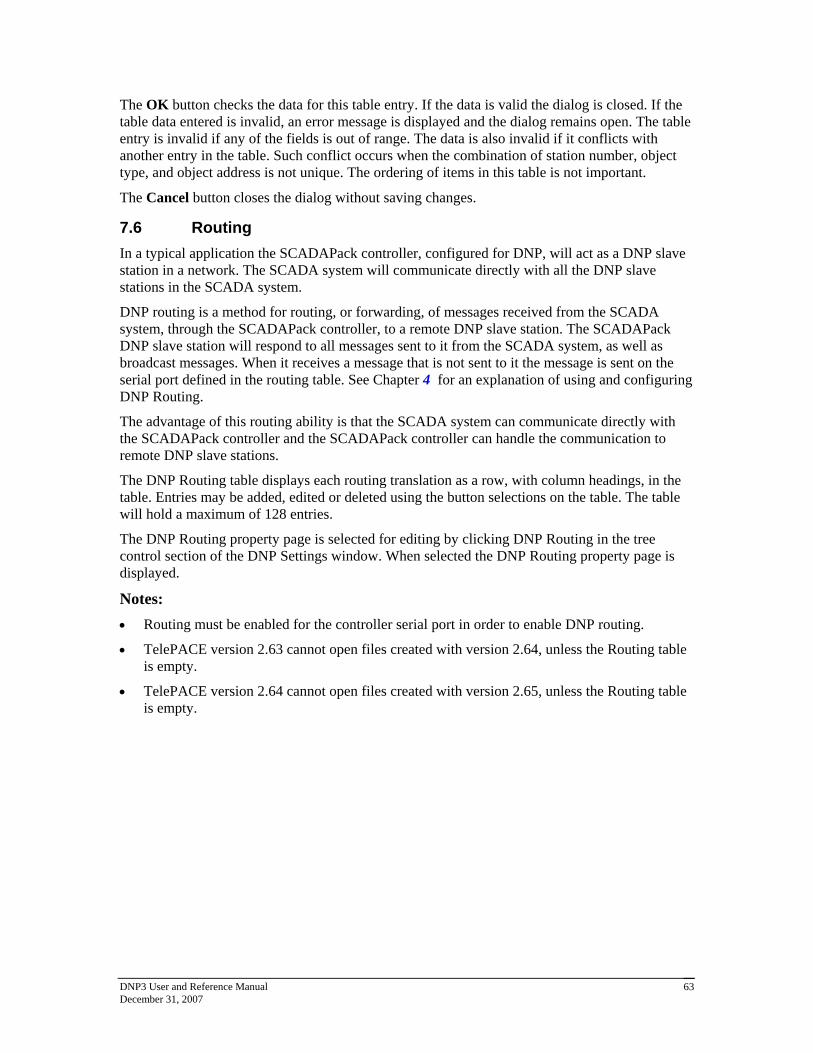
DNP3 User and Reference Manual December 31, 2007
63
The OK button checks the data for this table entry. If the data is valid the dialog is closed. If the table data entered is invalid, an error message is displayed and the dialog remains open. The table entry is invalid if any of the fields is out of range. The data is also invalid if it conflicts with another entry in the table. Such conflict occurs when the combination of station number, object type, and object address is not unique. The ordering of items in this table is not important.
The Cancel button closes the dialog without saving changes.
7.6 Routing
In a typical application the SCADAPack controller, configured for DNP, will act as a DNP slave station in a network. The SCADA system will communicate directly with all the DNP slave stations in the SCADA system.
DNP routing is a method for routing, or forwarding, of messages received from the SCADA system, through the SCADAPack controller, to a remote DNP slave station. The SCADAPack DNP slave station will respond to all messages sent to it from the SCADA system, as well as broadcast messages. When it receives a message that is not sent to it the message is sent on the serial port defined in the routing table. See Chapter 4 for an explanation of using and configuring DNP Routing.
The advantage of this routing ability is that the SCADA system can communicate directly with the SCADAPack controller and the SCADAPack controller can handle the communication to remote DNP slave stations.
The DNP Routing table displays each routing translation as a row, with column headings, in the table. Entries may be added, edited or deleted using the button selections on the table. The table will hold a maximum of 128 entries.
The DNP Routing property page is selected for editing by clicking DNP Routing in the tree control section of the DNP Settings window. When selected the DNP Routing property page is displayed.
Notes:
Routing must be enabled for the controller serial port in order to enable DNP routing.
TelePACE version 2.63 cannot open files created with version 2.64, unless the Routing table is empty.
TelePACE version 2.64 cannot open files created with version 2.65, unless the Routing table is empty.

DNP3 User and Reference Manual December 31, 2007
64
The Station column displays the address of the remote DNP station.
The Port column displays the serial communications port, which should be used to communicate with this DNP station.
The Retries column displays the maximum number of Data Link retries, which should be used for this DNP station in the case of communication errors.
The Timeout column displays the maximum time (in milliseconds) to wait for a Data Link response before retrying or failing the message.
The IP Address column displays the IP address of the remote DNP station.
The OK button saves the table data. No error checking is done on the table data.
The Cancel button closes the dialog without saving changes.
Select the Add button to enter a new row in the DNP Routing table. Selecting the Add button opens the Add/Edit DNP Route dialog.
Select the Edit button to modify the selected row in the DNP Routing table. Selecting the Edit button opens the Add/Edit DNP Route dialog containing the data from the selected row. This button is disabled if more than one row is selected. This button is disabled if there are no entries in the table.
The Delete button removes the selected rows from the table. This button is disabled if there are no entries in the table.
The Allow Duplicate Modbus Addresses checkbox determines if the Modbus I/O database addresses assigned to the DNP data points must be unique. Check this box if you want to allow more than one point to use the same Modbus address.

DNP3 User and Reference Manual December 31, 2007
65
Click on the column headings to sort the data. Clicking once sorts the data in ascending order. Clicking again sorts the data in descending order.
7.6.1 Add/Edit DNP Route Dialog
This dialog is used to edit an entry or add a new entry in the DNP Routing table.
The Station edit control displays the address of the remote DNP station. Valid values for this field are from 0 to 65519.
The Port combo box displays the communications port, which should be used to communicate with the remote DNP station. This combo box contains list of the valid communications ports, which will depend on the type of controller. For SCADAPack 350, SCADAPack 32 and SCADAPack 32P controllers the list will contain DNP in TCP and DNP in UDP in addition to the serial port designations, COM1, COM2 etc.
The IP Address edit control is only enabled if the controller type is a SCADAPack 350, SCADAPack 32 or SCADAPack 32P. Enter the IP address of the remote DNP station.
The Data Link Retries edit control displays the maximum number of Data Link retries which should be used for this DNP station in the case of communication errors. This field overrides the Data Link Retries field in the global DNP parameters set in the Data Link Layer configuration. Valid values for this field are 0 to 255.
The Data Link Timeout edit control displays the maximum time (in milliseconds) to wait for a Data Link response before retrying or failing the message. This field overrides the Data Link Timeout field in the global DNP parameters in the Data Link Layer configuration. Valid values for this field are 100 to 60000, in multiples of 100.
The phone number parameters allow automatic dialing for stations that use dial-up ports. The Phone Number parameters are enabled only when the Port selected is a serial port.
The Primary Phone Number is the dialing string that will be used for the primary connection to the station. The controller will make 1 or more attempts, as configured in the Application layer, to connect using this number. If this connection fails then the Secondary Phone Number will be dialed, if it is entered.
Valid values are any ASCII string. The maximum length is 32 characters. Leave this blank if you are not using a dial-up connection. The default value is blank. The serial port type must be set to RS-232 Modem for dial-up operation.

DNP3 User and Reference Manual December 31, 2007
66
The Secondary Phone Number is the dialing string that will be used for the secondary connection to the station. The controller will make 1 or more attempts, as configured in the Application layer, to connect using this number. This number is used after the primary connection fails on all attempts.
Valid values are any ASCII string. The maximum length is 32 characters. Leave this blank if you are not using a dial-up connection. The default value is blank. The serial port type must be set to RS-232 Modem for dial-up operation.
The OK button checks the data for this table entry. If the data is valid the dialog is closed. If the table data entered is invalid, an error message is displayed and the dialog remains open. The table entry is invalid if any of the fields is out of range. The data is also invalid if it conflicts with another entry in the table.
The Cancel button closes the dialog without saving changes.
7.6.2 Dynamic Routing
In addition to the configured routing table, there is an internal dynamic routing entry. This entry is not shown in the routing table. The dynamic routing entry listens to incoming messages and learns the address of the remote station and the communication port used for communicating with it.
If there is no entry in the routing table, the RTU will use the dynamic routing entry to respond to a message on the same communication port as the incoming message.
The dynamic routing entry is not cleared on initialization. This is deliberate, and is important for controllers that need to be remotely reconfigured. In this case the host can initialize the controller without losing the communications link.
Note: Dynamic routing should not be used in a master station. Configure all slave stations in the routing table.
7.7 Binary Inputs Configuration
The Binary Inputs property page is selected for editing by clicking Binary Inputs in the tree control section of the DNP Settings window. When selected the Binary Inputs property page is active.
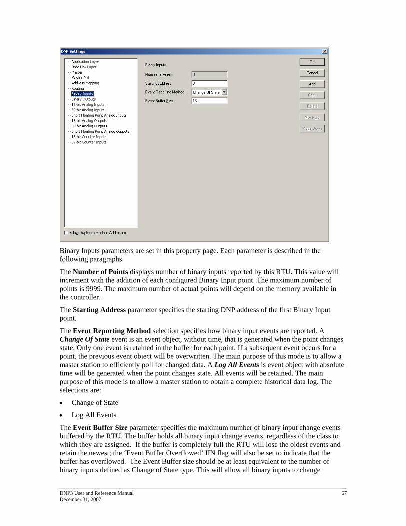
DNP3 User and Reference Manual December 31, 2007
67
Binary Inputs parameters are set in this property page. Each parameter is described in the following paragraphs.
The Number of Points displays number of binary inputs reported by this RTU. This value will increment with the addition of each configured Binary Input point. The maximum number of points is 9999. The maximum number of actual points will depend on the memory available in the controller.
The Starting Address parameter specifies the starting DNP address of the first Binary Input point.
The Event Reporting Method selection specifies how binary input events are reported. A Change Of State event is an event object, without time, that is generated when the point changes state. Only one event is retained in the buffer for each point. If a subsequent event occurs for a point, the previous event object will be overwritten. The main purpose of this mode is to allow a master station to efficiently poll for changed data. A Log All Events is event object with absolute time will be generated when the point changes state. All events will be retained. The main purpose of this mode is to allow a master station to obtain a complete historical data log. The selections are:
Change of State
Log All Events
The Event Buffer Size parameter specifies the maximum number of binary input change events buffered by the RTU. The buffer holds all binary input change events, regardless of the class to which they are assigned. If the buffer is completely full the RTU will lose the oldest events and retain the newest; the ‘Event Buffer Overflowed’ IIN flag will also be set to indicate that the buffer has overflowed. The Event Buffer size should be at least equivalent to the number of binary inputs defined as Change of State type. This will allow all binary inputs to change

DNP3 User and Reference Manual December 31, 2007
68
simultaneously without losing any events. The value of this parameter depends on how often binary input change events occur and the rate at which the events are reported to the master station. The valid values for this parameter are 0 - 65535. Default value is 16.
The Allow Duplicate Modbus Addresses checkbox determines if the Modbus I/O database addresses assigned to the DNP data points must be unique. Check this box if you want to allow more than one point to use the same Modbus address.
7.7.1 Adding Binary Inputs
Binary Inputs are added to the DNP configuration using the Binary Input property page. To add a Binary Input:
Select Binary Inputs in the tree control section of the DNP Settings window.
Click the Add button in the Binary Inputs property page.
The Binary Input property page is now displayed.
Edit the Binary Input parameters as required and then click the Add button.
As Binary Inputs are defined they are added as leaves to the Binary Inputs branch of the tree control. When Binary Inputs are defined the Binary Inputs branch will display a collapse / expand control to the left of the branch. Click this control to display all defined Binary Inputs.
The Binary Input parameters are described in the following paragraphs.

DNP3 User and Reference Manual December 31, 2007
69
The DNP Address window displays the DNP Binary Input address of the point. Each Binary Input is assigned a DNP address as they are defined. The DNP point address starts at the value defined in the Binary Inputs configuration dialog and increments by one with each defined Input.
The Modbus Address parameter specifies the Modbus address of the Binary Input assigned to the DNP Address. The SCADAPack and Micro16 controllers use Modbus addressing for all digital inputs. Refer to the I/O Database Registers section of the TelePACE Ladder Logic Reference and User Manual for complete information on digital input addressing in the SCADAPack and Micro16 controllers. Valid Modbus addresses are:
00001 through 09999
10001 through 19999
The Class of Event Object parameter specifies the event object class the Binary Input is assigned. The selections are:
None
Class 1
Class 2
Class 3
The Debounce parameter limits the frequency of change events. The input must remain in the same state for the debounce time for a change of state to be detected. Note that the input is sampled every 0.1s. Changes shorter than the sample time cannot be detected. Valid values are 0 to 65535 tenths of seconds. The value 0 means no debounce. The default value is 0.
The Allow Duplicate Modbus Addresses checkbox determines if the Modbus I/O database addresses assigned to the DNP data points must be unique. Check this box if you want to allow more than one point to use the same Modbus address.
Click the OK button to accept the Binary Input parameters and close the DNP Settings dialog.
Click the Cancel button to close the dialog without saving any changes.
Click the Add button to add the current Binary Input to the DNP configuration.
Click the Copy button to copy the current Binary Input parameters to the next DNP Address.
Click the Delete button to delete the current Binary Input.
Click the Move Up button to move the current Binary Input up one position in the tree control branch.
Click the Move Down button to move the current Binary Input down one position in the tree control branch.
7.8 Binary Outputs Configuration
The Binary Outputs property page is selected for editing by clicking Binary Outputs in the tree control section of the DNP Settings window. When selected the Binary Outputs property page is active.

DNP3 User and Reference Manual December 31, 2007
70
Binary Outputs parameters are viewed in this property page.
The Number of Points displays the number of binary outputs reported by this RTU. This value will increment with the addition of each configured Binary Output point. The maximum number of points is 9999. The maximum number of actual points will depend on the memory available in the controller.
The Starting Address parameter specifies the starting DNP address of the first Binary Output point.
The Allow Duplicate Modbus Addresses checkbox determines if the Modbus I/O database addresses assigned to the DNP data points must be unique. Check this box if you want to allow more than one point to use the same Modbus address.
7.8.1 Adding Binary Outputs
Binary Outputs are added to the DNP configuration using the Binary Output property page. To add a Binary Output:
Select Binary Outputs in the tree control section of the DNP Settings window.
Click the Add button in the Binary Outputs property page.
The Binary Output property page is now displayed.
Edit the Binary Output parameters as required and then click the Add button.
As Binary Outputs are defined they are added as leaves to the Binary Outputs branch of the tree control. When Binary Outputs are defined the Binary Outputs branch will display a collapse / expand control to the left of the branch. Click this control to display all defined Binary Outputs.

DNP3 User and Reference Manual December 31, 2007
71
The Binary Output parameters are described in the following paragraphs.
The DNP Address window displays the DNP Binary Output address of the point. Each Binary Output is assigned a DNP address as they are defined. The DNP point address starts at the value defined in the Binary Outputs dialog and increments by one with each defined Output.
The Modbus Address 1 parameter specifies the Modbus address of the Binary Output assigned to the DNP Address. The SCADAPack and Micro16 controllers use Modbus addressing for all digital outputs. Refer to the I/O Database Registers section of the TelePACE Ladder Logic Reference Manual for complete information on digital output addressing in the SCADAPack and Micro16 controllers. Valid Modbus addresses are:
00001 through 09999
The Modbus Address 2 parameter specifies the second Modbus address of the second Binary Output assigned to the DNP Address when the Paired control type is selected. This selection is not active when the control type is Not Paired. Valid Modbus addresses are:
00001 through 09999
The Control Type parameter specifies whether the Binary Output is a paired control or not. If it is a paired control, i.e. trip/close output type, this means that the DNP address is associated to two physical control outputs and requires two Modbus addresses per DNP address. Control type selections are:
Paired
Not Paired
The Allow Duplicate Modbus Addresses checkbox determines if the Modbus I/O database addresses assigned to the DNP data points must be unique. Check this box if you want to allow more than one point to use the same Modbus address.

DNP3 User and Reference Manual December 31, 2007
72
Click the OK button to accept the Binary Output parameters and close the DNP Settings dialog.
Click the Cancel button to close the dialog without saving any changes.
Click the Add button to add the current Binary Output to the DNP configuration.
Click the Copy button to copy the current Binary Output parameters to the next DNP Address.
Click the Delete button to delete the current Binary Output.
Click the Move Up button to move the current Binary Output up one position in the tree control branch.
Click the Move Down button to move the current Binary Output down one position in the tree control branch.
7.9 16–Bit Analog Inputs Configuration
The 16-Bit Analog Inputs property page is selected for editing by clicking 16-Bit Analog Inputs in the tree control section of the DNP Settings window. When selected the 16-Bit Analog Inputs property page is active.
16-Bit Analog Inputs parameters are set in this property page. Each parameter is described in the following paragraphs.
The Number of Points displays the number of 16 bit analog inputs reported by the RTU. This value will increment with the addition of each configured 16-Bit Analog Input point. The maximum number of points is 9999. The maximum number of actual points will depend on the memory available in the controller.
The Starting Address parameter specifies the DNP address of the first 16-bit Analog Input point.

DNP3 User and Reference Manual December 31, 2007
73
The Event Reporting Method selection specifies how 16-bit Analog Input events are reported. A Change Of State event is an event object, without time, that is generated when the point changes state. Only one event is retained in the buffer for each point. If a subsequent event occurs for a point, the previous event object will be overwritten. The main purpose of this mode is to allow a master station to efficiently poll for changed data. A Log All Events event object with absolute time will be generated when the point changes state. All events will be retained. The main purpose of this mode is to allow a master station to obtain a complete historical data log. The selections are:
Change of State
Log All Events
The Event Buffer Size parameter specifies the maximum number of 16-Bit Analog Input change events buffered by the RTU. The buffer holds all 16-Bit Analog Input events, regardless of the class to which they are assigned. If the buffer is completely full the RTU will lose the oldest events and retain the newest; the ‘Event Buffer Overflowed’ IIN flag will also be set to indicate that the buffer has overflowed. The Event Buffer size should be at least equivalent to the number of 16-Bit Analog Inputs defined as Change of State type. That will allow all 16-Bit Analog Inputs to exceed the deadband simultaneously without losing any events. The value of this parameter is dependent on how often 16-Bit Analog Input events occur and the rate at which the events are reported to the master station. The valid values for this parameter are 0 - 65535. Default value is 16.
For SCADAPack 32 and SCADAPack 32P controllers analog input events are processed by the DNP driver at a rate of 100 events every 100 ms. If more than 100 analog input events need to be processed they are processed sequentially in blocks of 100 until all events are processed. This allows the processing of 1000 analog input events per second.
For SCADASense Series of controllers, SCADAPack 100, SCADAPack LP, SCADAPack and Micro16 controllers analog input events are processed by the DNP driver at a rate of 20 events every 100 ms. If more than 20 analog input events need to be processed they are processed sequentially in blocks of 20 until all events are processed. This allows the processing of 200 analog input events per second.
The Allow Duplicate Modbus Addresses checkbox determines if the Modbus I/O database addresses assigned to the DNP data points must be unique. Check this box if you want to allow more than one point to use the same Modbus address.
7.9.1 Adding 16-Bit Analog Inputs
16-Bit Analog Inputs are added to the DNP configuration using the 16-Bit Analog Input property page. To add a 16-Bit Analog Input:
Select 16-Bit Analog Inputs in the tree control section of the DNP Settings window.
Click the Add button in the 16-Bit Analog Inputs property page.
The 16-Bit Analog Input property page is now displayed.
Edit the 16-Bit Analog Input parameters as required and then click the Add button.
As 16-Bit Analog Inputs are defined they are added as leaves to the 16-Bit Analog Inputs branch of the tree control. When 16-Bit Analog Inputs are defined the 16-Bit Analog Inputs branch will display a collapse / expand control to the left of the branch. Click this control to display all defined 16-Bit Analog Inputs.

DNP3 User and Reference Manual December 31, 2007
74
The 16-Bit Analog Input parameters are described in the following paragraphs.
The DNP Address window displays the DNP 16-Bit Analog Input address of the point. Each 16-Bit Analog Input is assigned a DNP address as they are defined. The DNP point address starts at the value set in the 16-bit Analog Input configuration dialog and increments by one with each defined 16-Bit Analog Input.
The Modbus Address parameter specifies the Modbus address of the 16-Bit Analog Input assigned to the DNP Address. The SCADAPack and Micro16 controllers use Modbus addressing for all analog inputs. Refer to the I/O Database Registers section of the TelePACE Ladder Logic Reference and User Manual for complete information on analog input addressing in the SCADAPack and Micro16 controllers. Valid Modbus addresses are:
30001 through 39999
40001 through 49999
The Class of Event Object parameter specifies the event object class assigned to the 16-Bit Analog Input is assigned. If Unsolicited reporting is not required for a point, it is recommended to set its Class to None. All data points automatically become members of Class 0 or None (static data). The selections are:
None
Class 1
Class 2
Class 3
The Deadband parameter specifies the minimum number of counts that the 16-Bit Analog Input must change since it was last reported in order to generate an event. Valid deadband values are 0 to 65535. A deadband of zero will cause any change to create an event.
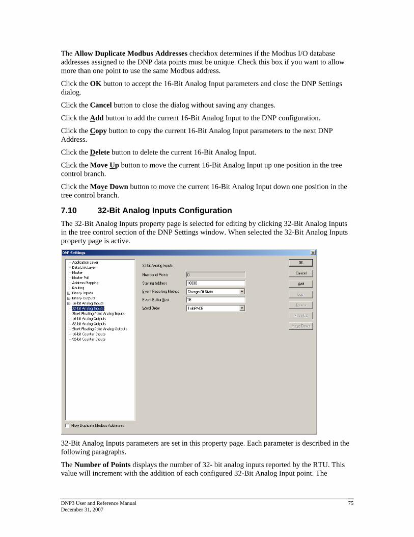
DNP3 User and Reference Manual December 31, 2007
75
The Allow Duplicate Modbus Addresses checkbox determines if the Modbus I/O database addresses assigned to the DNP data points must be unique. Check this box if you want to allow more than one point to use the same Modbus address.
Click the OK button to accept the 16-Bit Analog Input parameters and close the DNP Settings dialog.
Click the Cancel button to close the dialog without saving any changes.
Click the Add button to add the current 16-Bit Analog Input to the DNP configuration.
Click the Copy button to copy the current 16-Bit Analog Input parameters to the next DNP Address.
Click the Delete button to delete the current 16-Bit Analog Input.
Click the Move Up button to move the current 16-Bit Analog Input up one position in the tree control branch.
Click the Move Down button to move the current 16-Bit Analog Input down one position in the tree control branch.
7.10 32-Bit Analog Inputs Configuration
The 32-Bit Analog Inputs property page is selected for editing by clicking 32-Bit Analog Inputs in the tree control section of the DNP Settings window. When selected the 32-Bit Analog Inputs property page is active.
32-Bit Analog Inputs parameters are set in this property page. Each parameter is described in the following paragraphs.
The Number of Points displays the number of 32- bit analog inputs reported by the RTU. This value will increment with the addition of each configured 32-Bit Analog Input point. The

DNP3 User and Reference Manual December 31, 2007
76
maximum number of points is 9999. The maximum number of actual points will depend on the memory available in the controller.
The Starting Address parameter specifies the DNP address of the first 32-bit Analog Input point.
The Event Reporting Method selection specifies how 32-bit Analog Input events are reported. A Change Of State event is an event object, without time, that is generated when the point changes state. Only one event is retained in the buffer for each point. If a subsequent event occurs for a point, the previous event object will be overwritten. The main purpose of this mode is to allow a master station to efficiently poll for changed data. A Log All Events is event object with absolute time will be generated when the point changes state. All events will be retained. The main purpose of this mode is to allow a master station to obtain a complete historical data log. The selections are:
Change of State
Log All Events
The Event Buffer Size parameter specifies the maximum number of 32-Bit Analog Input change events buffered by the RTU. The buffer holds all 32-Bit Analog Input events, regardless of the class to which they are assigned. If the buffer is completely full the RTU will lose the oldest events and retain the newest; the ‘Event Buffer Overflowed’ IIN flag will also be set to indicate that the buffer has overflowed. The Event Buffer size should be at least equivalent to the number of 32-Bit Analog Inputs defined as Change of State type. That will allow all 32-Bit Analog Inputs to exceed the deadband simultaneously without losing any events. The value of this parameter is dependent on how often 32-Bit Analog Input events occur and the rate at which the events are reported to the master station. The valid values for this parameter are 0 - 65535. Default value is 16.
For SCADAPack 32 and SCADAPack 32P controllers analog input events are processed by the DNP driver at a rate of 100 events every 100 ms. If more than 100 analog input events need to be processed they are processed sequentially in blocks of 100 until all events are processed. This allows the processing of 1000 analog input events per second.
For SCADASense Series of controllers, SCADAPack 100, SCADAPack LP, SCADAPack and Micro16 controllers analog input events are processed by the DNP driver at a rate of 20 events every 100 ms. If more than 20 analog input events need to be processed they are processed sequentially in blocks of 20 until all events are processed. This allows the processing of 200 analog input events per second.
The Word Order selection specifies the word order of the 32-bit value. The selections are:
TelePACE Least Significant Word in first register.
ISaGRAF Most Significant Word in first register.
The Allow Duplicate Modbus Addresses checkbox determines if the Modbus I/O database addresses assigned to the DNP data points must be unique. Check this box if you want to allow more than one point to use the same Modbus address.
7.10.1 Adding 32-Bit Analog Inputs
32-Bit Analog Inputs are added to the DNP configuration using the 16-Bit Analog Input property page. To add a 32-Bit Analog Input:
Select 32-Bit Analog Inputs in the tree control section of the DNP Settings window.
Click the Add button in the 32-Bit Analog Inputs property page.

DNP3 User and Reference Manual December 31, 2007
77
The 32-Bit Analog Input property page is now displayed.
Edit the 32-Bit Analog Input parameters as required and then click the Add button.
As 32-Bit Analog Inputs are defined they are added as leaves to the 32-Bit Analog Inputs branch of the tree control. When 32-Bit Analog Inputs are defined the 32-Bit Analog Inputs branch will display a collapse / expand control to the left of the branch. Click this control to display all defined 32-Bit Analog Inputs.
The 32-Bit Analog Input parameters are described in the following paragraphs.
The DNP Address window displays the DNP 32-Bit Analog Input address of the point. Each 32-Bit Analog Input is assigned a DNP address as they are defined. The DNP point address starts at the value set in the 32-bit Analog Input configuration dialog and increments by one with each defined 32-Bit Analog Input.
The Modbus Address parameter specifies the Modbus addresses of the 32-Bit Analog Input assigned to the DNP Address. 32-Bit Analog Inputs use two consecutive Modbus registers for each assigned DNP Address, the address that is entered in this box and the next consecutive Modbus register. The SCADAPack and Micro16 controllers use Modbus addressing for all analog inputs. Refer to the I/O Database Registers section of the TelePACE Ladder Logic Reference and User Manual for complete information on analog input addressing in the SCADAPack and Micro16 controllers. Valid Modbus addresses are:
30001 through 39998
40001 through 49998
The Class of Event Object parameter specifies the event object class the 32-Bit Analog Input is assigned. If Unsolicited reporting is not required for a DNP point, it is recommended to set its Class 0 or None. All data points automatically become members of Class 0 or None (static data).The selections are:

DNP3 User and Reference Manual December 31, 2007
78
None
Class 1
Class 2
Class 3
The Deadband parameter specifies whether the RTU generates events. The value entered is the minimum number of counts that the 32-Bit Analog Input must change since it was last reported. Valid deadband values are 0 to 4,294,967,295. A deadband of zero will cause any change to create an event.
The Allow Duplicate Modbus Addresses checkbox determines if the Modbus I/O database addresses assigned to the DNP data points must be unique. Check this box if you want to allow more than one point to use the same Modbus address.
Click the OK button to accept the 32-Bit Analog Input parameters and close the DNP Settings dialog.
Click the Cancel button to close the dialog without saving any changes.
Click the Add button to add the current 32-Bit Analog Input to the DNP configuration.
Click the Copy button to copy the current 32-Bit Analog Input parameters to the next DNP Address.
Click the Delete button to delete the current 32-Bit Analog Input.
Click the Move Up button to move the current 32-Bit Analog Input up one position in the tree control branch.
Click the Move Down button to move the current 32-Bit Analog Input down one position in the tree control branch.
7.11 Short Floating Point Analog Inputs
The Short Floating Point Analog Inputs property page is selected for editing by clicking Short Floating Point Analog Inputs in the tree control section of the DNP Settings window. When selected the Short Floating Point Analog Inputs property page is active.

DNP3 User and Reference Manual December 31, 2007
79
Short Floating Point Analog Input parameters are set in this property page. Each parameter is described in the following paragraphs.
The Number of Points displays the number of Short Floating Point Analog Inputs reported by the RTU. This value will increment with the addition of each configured Short Floating Point Analog Input point. The maximum number of points is 9999. The maximum number of actual points will depend on the memory available in the controller.
The Starting Address parameter specifies the DNP address of the first Short Floating Point Analog Input point.
The Event Reporting Method selection specifies how Short Floating Point Analog Input events are reported. A Change Of State event is an event object, without time, that is generated when the point changes state. Only one event is retained in the buffer for each point. If a subsequent event occurs for a point, the previous event object will be overwritten. The main purpose of this mode is to allow a master station to efficiently poll for changed data. A Log All Events is event object with absolute time will be generated when the point changes state. All events will be retained. The main purpose of this mode is to allow a master station to obtain a complete historical data log. The selections are:
Change of State
Log All Events
The Event Buffer Size parameter specifies the maximum number of Short Floating Point Analog Input change events buffered by the RTU. The buffer holds all Short Floating Point analog input events, regardless of the class to which they are assigned. If the buffer is completely full the RTU will lose the oldest events and retain the newest; the ‘Event Buffer Overflowed’ IIN flag will also be set to indicate that the buffer has overflowed. The Event Buffer size should be at least equivalent to the number of Short Floating point analog inputs defined as Change of State type. That will allow all Short Floating Analog Point Inputs to exceed the deadband simultaneously

DNP3 User and Reference Manual December 31, 2007
80
without losing any events. The value of this parameter is dependent on how often Short Floating Point Analog Input events occur and the rate at which the events are reported to the master station. The valid values for this parameter are 0 - 65535. Default value is 16.
For SCADAPack 32 and SCADAPack 32P controllers analog input events are processed by the DNP driver at a rate of 100 events every 100 ms. If more than 100 analog input events need to be processed they are processed sequentially in blocks of 100 until all events are processed. This allows the processing of 1000 analog input events per second.
For SCADASense Series of controllers, SCADAPack 100, SCADAPack LP, SCADAPack and Micro16 controllers analog input events are processed by the DNP driver at a rate of 20 events every 100 ms. If more than 20 analog input events need to be processed they are processed sequentially in blocks of 20 until all events are processed. This allows the processing of 200 analog input events per second.
The Word Order selection specifies the word order of the 32-bit value. The selections are:
TelePACE / ISaGRAF (MSW First) Most Significant Word in first register.
Reverse (LSW First) Least Significant Word in first register.
The Allow Duplicate Modbus Addresses checkbox determines if the Modbus I/O database addresses assigned to the DNP data points must be unique. Check this box if you want to allow more than one point to use the same Modbus address.
7.11.1 Adding Short Floating Point Analog Inputs
Short Floating Point Analog Inputs are added to the DNP configuration using the 16-Bit Analog Input property page. To add a Short Floating Point Analog Input:
Select Short Floating Point Analog Input in the tree control section of the DNP Settings window.
Click the Add button in the Short Floating Point Analog Inputs property page.
The Short Floating Point Analog Input property page is now displayed.
Edit the Short Floating Point Analog Input parameters as required and then click the Add button.
As Short Floating Point Analog Inputs are defined they are added as leaves to the Short Floating Point Analog Inputs branch of the tree control. When Short Floating Point Analog Inputs are defined the Short Floating Point Analog Inputs branch will display a collapse / expand control to the left of the branch. Click this control to display all defined Short Floating Point Analog Inputs.

DNP3 User and Reference Manual December 31, 2007
81
The Short Floating Point Analog Input parameters are described in the following paragraphs.
The DNP Address window displays the DNP Short Floating Point Analog Input address of the point. Each Short Floating Point Analog Input is assigned a DNP address as they are defined. The DNP point address starts at the value set in the Short Floating Point Analog Input configuration dialog and increments by one with each defined Short Floating Point Analog Input.
The Modbus Address parameter specifies the Modbus addresses of the Short Floating Point Analog Input assigned to the DNP Address. Short Floating Point Analog Inputs use two consecutive Modbus registers for each assigned DNP Address, the address that is entered in this box and the next consecutive Modbus register. The SCADAPack and Micro16 controllers use Modbus addressing for all analog inputs. Refer to the I/O Database Registers section of the TelePACE Ladder Logic Reference and User Manual for complete information on analog input addressing in the SCADAPack and Micro16 controllers. Valid Modbus addresses are:
30001 through 39998
40001 through 49998
The Class of Event Object parameter specifies the event object class the Short Floating Point Analog Input is assigned. If Unsolicited reporting is not required for a DNP point, it is recommended to set its Class 0 or None. The selections are:
None
Class 1
Class 2
Class 3
The Deadband parameter specifies whether the RTU generates events. The value entered is the minimum number of counts that the Short Floating Point Analog Input must change since it was

DNP3 User and Reference Manual December 31, 2007
82
last reported. Setting this value to zero disables generating events for the Short Floating Point Analog Inputs.
The Allow Duplicate Modbus Addresses checkbox determines if the Modbus I/O database addresses assigned to the DNP data points must be unique. Check this box if you want to allow more than one point to use the same Modbus address.
Click the OK button to accept the Short Floating Point Analog Input parameters and close the DNP Settings dialog.
Click the Cancel button to close the dialog without saving any changes.
Click the Add button to add the current Short Floating Point Analog Input to the DNP configuration.
Click the Copy button to copy the current Short Floating Point Analog Input parameters to the next DNP Address.
Click the Delete button to delete the current Short Floating Point Analog Input.
Click the Move Up button to move the current Short Floating Point Analog Input up one position in the tree control branch.
Click the Move Down button to move the current Short Floating Point Analog Input down one position in the tree control branch.
7.12 16-Bit Analog Outputs Configuration
The 16-Bit Analog Outputs property page is selected for editing by clicking 16-Bit Analog Outputs in the tree control section of the DNP Settings window. When selected the 16-Bit Analog Outputs property page is active.
16-Bit Analog Outputs parameters are viewed in this property page.

DNP3 User and Reference Manual December 31, 2007
83
The Number of Points displays the number of 16-Bit Analog Outputs reported by this RTU. This value will increment with the addition of each configured 16-Bit Analog Input point. The maximum number of points is 9999. The maximum number of actual points will depend on the memory available in the controller.
The Starting Address parameter specifies the DNP address of the first 16-bit Analog Output point.
The Allow Duplicate Modbus Addresses checkbox determines if the Modbus I/O database addresses assigned to the DNP data points must be unique. Check this box if you want to allow more than one point to use the same Modbus address.
7.12.1 Adding 16-Bit Analog Outputs
16-Bit Analog Outputs are added to the DNP configuration using the 16-Bit Analog Outputs property page. To add a 16-Bit Analog Output:
Select 16-Bit Analog Outputs in the tree control section of the DNP Settings window.
Click the Add button in the 16-Bit Analog Outputs property page.
The 16-Bit Analog Output property page is now displayed.
Edit the 16-Bit Analog Outputs parameters as required and then click the Add button.
As 16-Bit Analog Outputs are defined they are added as leaves to the 16-Bit Analog Output branch of the tree control. When 16-Bit Analog Outputs are defined the 16-Bit Analog Outputs branch will display a collapse / expand control to the left of the branch. Click this control to display all defined 16-Bit Analog Outputs.
The 16-Bit Analog Outputs parameters are described in the following paragraphs.

DNP3 User and Reference Manual December 31, 2007
84
The DNP Address window displays the DNP 16-Bit Analog Output address of the point. Each 16-Bit Analog Output is assigned a DNP address as they are defined. The DNP point address starts at the value set in the 16-bit Analog Output configuration dialog and increments by one with each defined 16-Bit Analog Output.
The Modbus Address parameter specifies the Modbus address of the 16-Bit Analog Output assigned to the DNP Address. The SCADAPack and Micro16 controllers use Modbus addressing for all analog outputs. Refer to the I/O Database Registers section of the TelePACE Ladder Logic Reference and User Manual for complete information on analog output addressing in the SCADAPack and Micro16 controllers. Valid Modbus addresses are:
40001 through 49999
The Allow Duplicate Modbus Addresses checkbox determines if the Modbus I/O database addresses assigned to the DNP data points must be unique. Check this box if you want to allow more than one point to use the same Modbus address.
Click the OK button to accept the 16-Bit Analog Output parameters and close the DNP Settings dialog.
Click the Cancel button to close the dialog without saving any changes.
Click the Add button to add the current 16-Bit Analog Output to the DNP configuration.
Click the Copy button to copy the current 16-Bit Analog Output parameters to the next DNP Address.
Click the Delete button to delete the current 16-Bit Analog Output.
Click the Move Up button to move the current 16-Bit Analog Output up one position in the tree control branch.
Click the Move Down button to move the current 16-Bit Analog Output down one position in the tree control branch.
7.13 32-Bit Analog Outputs Configuration
The 32-Bit Analog Outputs property page is selected for editing by clicking 32-Bit Analog Outputs in the tree control section of the DNP Settings window. When selected the 32-Bit Analog Outputs property page is active.
DNP3 User and Reference Manual December 31, 2007
85
32-Bit Analog Outputs parameters are viewed in this property page.
The Number of Points displays the number of 32-Bit Analog Outputs reported by this RTU. This value will increment with the addition of each configured 32-Bit Analog Output point. The maximum number of points is 9999. The maximum number of actual points will depend on the memory available in the controller.
The Starting Address parameter specifies the DNP address of the first 16-bit Analog Output point.
The Word Order selection specifies the word order of the 32-bit value. The selections are:
TelePACE Least Significant Word in first register.
ISaGRAF Most Significant Word in first register.
The Allow Duplicate Modbus Addresses checkbox determines if the Modbus I/O database addresses assigned to the DNP data points must be unique. Check this box if you want to allow more than one point to use the same Modbus address.
7.13.1 Adding 32-Bit Analog Outputs
32-Bit Analog Outputs are added to the DNP configuration using the 32-Bit Analog Outputs property page. To add a 32-Bit Analog Output:
Select 32-Bit Analog Outputs in the tree control section of the DNP Settings window.
Click the Add button in the 16-Bit Analog Outputs property page.
The 32-Bit Analog Output property page is now displayed.
Edit the 32-Bit Analog Outputs parameters as required and then click the Add button.
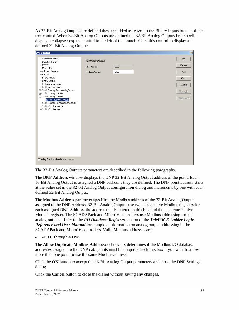
DNP3 User and Reference Manual December 31, 2007
86
As 32-Bit Analog Outputs are defined they are added as leaves to the Binary Inputs branch of the tree control. When 32-Bit Analog Outputs are defined the 32-Bit Analog Outputs branch will display a collapse / expand control to the left of the branch. Click this control to display all defined 32-Bit Analog Outputs.
The 32-Bit Analog Outputs parameters are described in the following paragraphs.
The DNP Address window displays the DNP 32-Bit Analog Output address of the point. Each 16-Bit Analog Output is assigned a DNP address s they are defined. The DNP point address starts at the value set in the 32-bit Analog Output configuration dialog and increments by one with each defined 32-Bit Analog Output.
The Modbus Address parameter specifies the Modbus address of the 32-Bit Analog Output assigned to the DNP Address. 32-Bit Analog Outputs use two consecutive Modbus registers for each assigned DNP Address, the address that is entered in this box and the next consecutive Modbus register. The SCADAPack and Micro16 controllers use Modbus addressing for all analog outputs. Refer to the I/O Database Registers section of the TelePACE Ladder Logic Reference and User Manual for complete information on analog output addressing in the SCADAPack and Micro16 controllers. Valid Modbus addresses are:
40001 through 49998
The Allow Duplicate Modbus Addresses checkbox determines if the Modbus I/O database addresses assigned to the DNP data points must be unique. Check this box if you want to allow more than one point to use the same Modbus address.
Click the OK button to accept the 16-Bit Analog Output parameters and close the DNP Settings dialog.
Click the Cancel button to close the dialog without saving any changes.

DNP3 User and Reference Manual December 31, 2007
87
Click the Add button to add the current 32-Bit Analog Output to the DNP configuration.
Click the Copy button to copy the current 32-Bit Analog Output parameters to the next DNP Address.
Click the Delete button to delete the current 32-Bit Analog Output.
Click the Move Up button to move the current 32-Bit Analog Output up one position in the tree control branch.
Click the Move Down button to move the current 32-Bit Analog Output down one position in the tree control branch.
7.14 Short Floating Point Analog Outputs
The Short Floating Point Analog Outputs property page is selected for editing by clicking Short Floating Point Analog Outputs in the tree control section of the DNP Settings window. When selected the Short Floating Point Analog Outputs property page is active.
Short Floating Point Analog Output parameters are set in this property page. Each parameter is described in the following paragraphs.
The Number of Points displays the number of Short Floating Point Analog Outputs reported by the RTU. This value will increment with the addition of each configured Short Floating Point Analog Input point. The maximum number of points is 9999. The maximum number of actual points will depend on the memory available in the controller.
The Starting Address parameter specifies the DNP address of the first Short Floating Point Analog Output point.
The Word Order selection specifies the word order of the 32-bit value. The selections are:

DNP3 User and Reference Manual December 31, 2007
88
TelePACE / ISaGRAF (MSW First) Most Significant Word in first register.
Reverse (LSW First) Least Significant Word in first register.
The Allow Duplicate Modbus Addresses checkbox determines if the Modbus I/O database addresses assigned to the DNP data points must be unique. Check this box if you want to allow more than one point to use the same Modbus address.
7.14.1 Adding Short Floating Point Analog Outputs
Short Floating Point Analog Outputs are added to the DNP configuration using the Short Floating Point Analog Output property page. To add a Short Floating Point Analog Output:
Select Short Floating Point Analog Output in the tree control section of the DNP Settings window.
Click the Add button in the Short Floating Point Analog Inputs property page.
The Short Floating Point Analog Output property page is now displayed.
Edit the Short Floating Point Analog Output parameters as required and then click the Add button.
As Short Floating Point Analog Outputs are defined they are added as leaves to the Short Floating Point Analog Outputs branch of the tree control. When Short Floating Point Analog Outputs are defined the Short Floating Point Analog Outputs branch will display a collapse / expand control to the left of the branch. Click this control to display all defined Short Floating Point Analog Outputs.
The Short Floating Point Analog Output parameters are described in the following paragraphs.

DNP3 User and Reference Manual December 31, 2007
89
The DNP Address window displays the DNP Short Floating Point Analog Output address of the point. Each Short Floating Point Analog Output is assigned a DNP address as they are defined. The DNP point address starts at the value set in the Short Floating Point Analog Output configuration dialog and increments by one with each defined Short Floating Point Analog Output.
The Modbus Address parameter specifies the Modbus addresses of the Short Floating Point Analog Output assigned to the DNP Address. Short Floating Point Analog Outputs use two consecutive Modbus registers for each assigned DNP Address, the address that is entered in this box and the next consecutive Modbus register. The SCADAPack and Micro16 controllers use Modbus addressing for all analog inputs. Refer to the I/O Database Registers section of the TelePACE Ladder Logic Reference and User Manual for complete information on analog input addressing in the SCADAPack and Micro16 controllers. Valid Modbus addresses are:
30001 through 39998
40001 through 49998
The Allow Duplicate Modbus Addresses checkbox determines if the Modbus I/O database addresses assigned to the DNP data points must be unique. Check this box if you want to allow more than one point to use the same Modbus address.
Click the OK button to accept the Short Floating Point Analog Input parameters and close the DNP Settings dialog.
Click the Cancel button to close the dialog without saving any changes.
Click the Add button to add the current Short Floating Point Analog Input to the DNP configuration.
Click the Copy button to copy the current Short Floating Point Analog Input parameters to the next DNP Address.
Click the Delete button to delete the current Short Floating Point Analog Input.
Click the Move Up button to move the current Short Floating Point Analog Input up one position in the tree control branch.
Click the Move Down button to move the current Short Floating Point Analog Input down one position in the tree control branch.
7.15 16–Bit Counter Inputs Configuration
The 16-Bit Counter Inputs property page is selected for editing by clicking 16-Bit Counter Inputs in the tree control section of the DNP Settings window. When selected the 16-Bit Counter Inputs property page is active.

DNP3 User and Reference Manual December 31, 2007
90
16-Bit Counter Inputs parameters are set in this property page. Each parameter is described in the following paragraphs.
The Number of Points displays the number of 16-Bit Counter Inputs reported by the RTU. This value will increment with the addition of each configured 16-Bit Counter Inputs point. The maximum number of points is 9999. The maximum number of actual points will depend on the memory available in the controller.
The Starting Address parameter specifies the DNP address of the first 16-Bit Counter Input point.
The Event Reporting Method selection specifies how 16-Bit Counter Input events are reported. A Change Of State event is an event object, without time, that is generated when the point changes state. Only one event is retained in the buffer for each point. If a subsequent event occurs for a point, the previous event object will be overwritten. The main purpose of this mode is to allow a master station to efficiently poll for changed data. A Log All Events is event object with absolute time will be generated when the point changes state. All events will be retained. The main purpose of this mode is to allow a master station to obtain a complete historical data log. The selections are:
Change of State
Log All Events
The Event Buffer Size parameter specifies the maximum number of 16-Bit Counter Input change without time events buffered by the RTU. The buffer holds all 16-Bit Counter Input events, regardless of the class to which they are assigned. If the buffer fills to 90 percent the RTU will send a buffer overflow event to the master station. If the buffer is completely full the RTU will lose the oldest events and retain the newest. The Event Buffer size should be at least equivalent to the number of 16-Bit Analog Inputs defined as Change of State type. That will allow all 16-Bit Counter Inputs to exceed the threshold simultaneously without losing any events. The value of this parameter is dependent on how often 16-Bit Counter Input events occur and the rate at which

DNP3 User and Reference Manual December 31, 2007
91
the events are reported to the master station. The valid values for this parameter are 0 - 65535. Default value is 16.
For SCADAPack 32 and SCADAPack 32P controllers counter input events are processed by the DNP driver at a rate of 100 events every 100 ms. If more than 100 counter input events need to be processed they are processed sequentially in blocks of 100 until all events are processed. This allows the processing of 1000 counter input events per second.
For SCADASense Series of controllers, SCADAPack 100, SCADAPack LP, SCADAPack and Micro16 controllers counter input events are processed by the DNP driver at a rate of 20 events every 100 ms. If more than 20 counter input events need to be processed they are processed sequentially in blocks of 20 until all events are processed. This allows the processing of 200 counter input events per second.
The Allow Duplicate Modbus Addresses checkbox determines if the Modbus I/O database addresses assigned to the DNP data points must be unique. Check this box if you want to allow more than one point to use the same Modbus address.
7.15.1 Adding 16-Bit Counter Inputs
16-Bit Counter Inputs are added to the DNP configuration using the 16-Bit Counter Inputs property page. To add a 16-Bit Counter Input:
Select 16-Bit Counter Inputs in the tree control section of the DNP Settings window.
Click the Add button in the 16-Bit Counter Inputs property page.
The 16-Bit Counter Input property page is now displayed.
Edit the 16-Bit Counter Inputs parameters as required and then click the Add button.
As 16-Bit Counter Inputs are defined they are added as leaves to the 16-Bit Counter Inputs branch of the tree control. When 16-Bit Counter Inputs are defined the 16-Bit Counter Inputs branch will display a collapse / expand control to the left of the branch. Click this control to display all defined 16-Bit Counter Inputs.

DNP3 User and Reference Manual December 31, 2007
92
The 16-Bit Counter Input parameters are described in the following paragraphs.
The DNP Address window displays the DNP 16-Bit Counter Input address of the point. Each 16-Bit Counter Input is assigned a DNP address s they are defined. The DNP point address starts at the value set in the 16-Bit Counter Input configuration dialog and increments by one with each defined 16-Bit Counter Input.
The Modbus Address parameter specifies the Modbus address of the 16-Bit Counter Input assigned to the DNP Address. The SCADAPack and Micro16 controllers use Modbus addressing for all counter inputs. Refer to the I/O Database Registers section of the TelePACE Ladder Logic Reference and User Manual for complete information on analog input addressing in the SCADAPack and Micro16 controllers. Valid Modbus addresses are:
30001 through 39999
40001 through 49999
The Class of Event Object parameter specifies the event object class the 16-Bit Counter Input is assigned. If Unsolicited reporting is not required for a DNP point, it is recommended to set its Class 0 or None. The selections are:
None
Class 1
Class 2
Class 3
The Threshold parameter specifies whether the RTU generates events. The value entered is the minimum number of counts that the 16-Bit Counter Input must change since it was last reported.
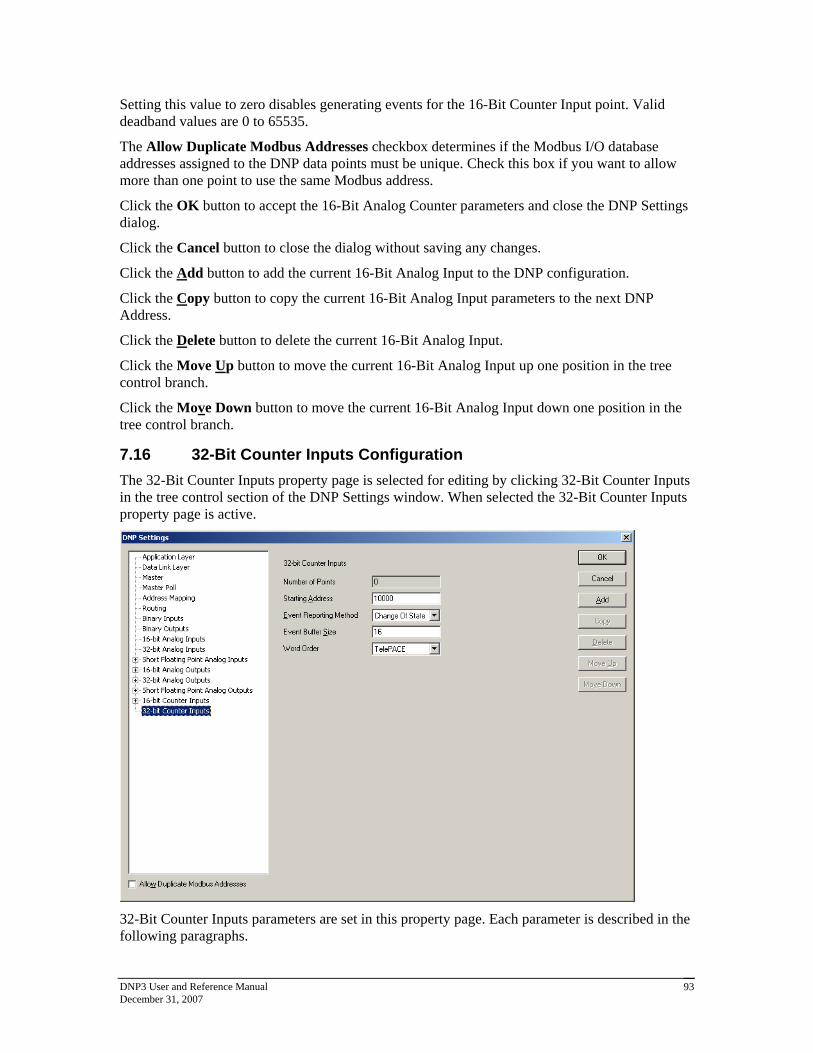
DNP3 User and Reference Manual December 31, 2007
93
Setting this value to zero disables generating events for the 16-Bit Counter Input point. Valid deadband values are 0 to 65535.
The Allow Duplicate Modbus Addresses checkbox determines if the Modbus I/O database addresses assigned to the DNP data points must be unique. Check this box if you want to allow more than one point to use the same Modbus address.
Click the OK button to accept the 16-Bit Analog Counter parameters and close the DNP Settings dialog.
Click the Cancel button to close the dialog without saving any changes.
Click the Add button to add the current 16-Bit Analog Input to the DNP configuration.
Click the Copy button to copy the current 16-Bit Analog Input parameters to the next DNP Address.
Click the Delete button to delete the current 16-Bit Analog Input.
Click the Move Up button to move the current 16-Bit Analog Input up one position in the tree control branch.
Click the Move Down button to move the current 16-Bit Analog Input down one position in the tree control branch.
7.16 32-Bit Counter Inputs Configuration
The 32-Bit Counter Inputs property page is selected for editing by clicking 32-Bit Counter Inputs in the tree control section of the DNP Settings window. When selected the 32-Bit Counter Inputs property page is active.
32-Bit Counter Inputs parameters are set in this property page. Each parameter is described in the following paragraphs.

DNP3 User and Reference Manual December 31, 2007
94
The Number of Points displays the number of 32-Bit Counter Inputs reported by the RTU. This value will increment with the addition of each configured 32-Bit Counter Inputs point. The maximum number of points is 9999. The maximum number of actual points will depend on the memory available in the controller.
The Starting Address parameter specifies the DNP address of the first 32-Bit Counter Input point.
The Event Reporting Method selection specifies how 32-Bit Counter Input events are reported. A Change Of State event is an event object, without time, that is generated when the point changes state. Only one event is retained in the buffer for each point. If a subsequent event occurs for a point, the previous event object will be overwritten. The main purpose of this mode is to allow a master station to efficiently poll for changed data. A Log All Events is event object with absolute time will be generated when the point changes state. All events will be retained. The main purpose of this mode is to allow a master station to obtain a complete historical data log. The selections are:
Change of State
Log All Events
The Event Buffer Size parameter specifies the maximum number of 32-Bit Counter Input change events buffered by the RTU. The buffer holds all 32-Bt Counter Input events, regardless of the class to which they are assigned. If the buffer is completely full the RTU will lose the oldest events and retain the newest; the ‘Event Buffer Overflowed’ IIN flag will also be set to indicate that the buffer has overflowed. The Event Buffer size should be at least equivalent to the number of 32-Bit Counter Inputs defined as Change of State type. That will allow all 32-Bit Counter Inputs to exceed the deadband simultaneously without losing any events. The value of this parameter is dependent on how often 32-Bit Counter Input events occur and the rate at which the events are reported to the master station. The valid values for this parameter are 0 - 65535. Default value is 16.
For SCADAPack 32 and SCADAPack 32P controllers counter input events are processed by the DNP driver at a rate of 100 events every 100 ms. If more than 100 counter input events need to be processed they are processed sequentially in blocks of 100 until all events are processed. This allows the processing of 1000 counter input events per second.
For SCADASense Series of controllers, SCADAPack 100, SCADAPack LP, SCADAPack and Micro16 controllers counter input events are processed by the DNP driver at a rate of 20 events every 100 ms. If more than 20 counter input events need to be processed they are processed sequentially in blocks of 20 until all events are processed. This allows the processing of 200 counter input events per second.
The Word Order selection specifies the word order of the 32-bit value. The selections are:
TelePACE Least Significant Word in first register.
ISaGRAF Most Significant Word in first register.
The Allow Duplicate Modbus Addresses checkbox determines if the Modbus I/O database addresses assigned to the DNP data points must be unique. Check this box if you want to allow more than one point to use the same Modbus address.
7.16.1 Adding 32-Bit Counter Inputs
32-Bit Counter Inputs are added to the DNP configuration using the 16-Bit Counter Input property page. To add a 32-Bit Analog Input:

DNP3 User and Reference Manual December 31, 2007
95
Select 32-Bit Counter Inputs in the tree control section of the DNP Settings window.
Click the Add button in the 32-Bit Counter Inputs property page.
The 32-Bit Counter Input property page is now displayed.
Edit the 32-Bit Counter Input parameters as required and then click the Add button.
As 32-Bit Counter Inputs are defined they are added as leaves to the 32-Bit Counter Inputs branch of the tree control. When 32-Bit Counter Inputs are defined the 32-Bit Counter Inputs branch will display a collapse / expand control to the left of the branch. Click this control to display all defined 32-Bit Counter Inputs.
The 32-Bit Counter Input parameters are described in the following paragraphs.
The DNP Address window displays the DNP 32-Bit Counter Input address of the point. Each 32-Bit Counter Input is assigned a DNP address as they are defined. The DNP point address starts at the value set in the 32-Bit Counter Input configuration dialog and increments by one with each defined 32-Bit Counter Input.
The Modbus Address parameter specifies the Modbus addresses of the 32-Bit Counter Input assigned to the DNP Address. 32-Bit Counter Inputs use two consecutive Modbus registers for each assigned DNP Address, the address that is entered in this box and the next consecutive Modbus register. The SCADAPack and Micro16 controllers use Modbus addressing for all counter inputs. Refer to the I/O Database Registers section of the TelePACE Ladder Logic Reference and User Manual for complete information on analog input addressing in the SCADAPack and Micro16 controllers. Valid Modbus addresses are:
30001 through 39998
40001 through 49998

DNP3 User and Reference Manual December 31, 2007
96
The Class of Event Object parameter specifies the event object class the 32-Bit Counter Input is assigned. If Unsolicited reporting is not required for a DNP point, it is recommended to set its Class 0 or None. The selections are:
None
Class 1
Class 2
Class 3
The Threshold parameter specifies whether the RTU generates events. The value entered is the minimum number of counts that the 32-Bit Counter Input must change since it was last reported. Setting this value to zero disables generating events for the 32-Bit Counter Input point. Valid threshold values are 0 to 4,294,967,295.
The Allow Duplicate Modbus Addresses checkbox determines if the Modbus I/O database addresses assigned to the DNP data points must be unique. Check this box if you want to allow more than one point to use the same Modbus address.
Click the OK button to accept the 32-Bit Counter Input parameters and close the DNP Settings dialog.
Click the Cancel button to close the dialog without saving any changes.
Click the Add button to add the current 32-Bit Counter Input to the DNP configuration.
Click the Copy button to copy the current 32-Bit Counter Input parameters to the next DNP Address.
Click the Delete button to delete the current 32-Bit Counter Input.
Click the Move Up button to move the current 32-Bit Counter Input up one position in the tree control branch.
Click the Move Down button to move the current 32-Bit Counter Input down one position in the tree control branch.

DNP3 User and Reference Manual December 31, 2007
97
8 DNP Diagnostics DNP Diagnostics provide Master station and Outstation DNP diagnostics. The diagnostics provide detailed information on the status of DNP communication and DNP data points. This information is useful when debugging DNP station and network problems that may arise.
DNP diagnostics are available for local DNP information using the DNP Status command.
For TelePACE applications select Controller >> DNP Status from the menu bar. See Chapter 8 for information on DNP Status diagnostics.
For ISaGRAF applications select Tools >> Controller >> DNP Status from the program window menu bar.
SCADAPack 32 controllers support DNP master operations. DNP diagnostics are available for master stations using the DNP Master Status command.
For TelePACE applications select Controller >> DNP Master Status from the menu bar. See section 8.2 for information on DNP Master Status diagnostics.
For ISaGRAF applications select Tools >> Controller >> DNP Master Status from the program window menu bar.
DNP Diagnostics require firmware version 2.20 or newer for SCADAPack controllers and firmware version 1.50 or newer for SCADAPack 32 controllers. When an attempt is made to select the DNP Status or DNP Master Status command for controllers with firmware that does not support the commands an error message is displayed. An example of the error message is shown below.
To enable the use of DNP diagnostics you will need to upgrade the firmware in the controller to the newer version.
8.1 DNP Status
When the DNP Status command is selected the DNP Status dialog is displayed. This dialog shows the run-time DNP diagnostics and current data values for the local DNP points.
The DNP Status dialog has a number of selectable tabs and opens with the Overview tab selected. The following tabs are displayed.
Overview
Binary In (binary inputs information)
Binary Out (binary outputs information)
AIN-16 (16-bit analog inputs information)
AIN-32 (32-bit analog inputs information)
AIN-Float (short float analog inputs information)

DNP3 User and Reference Manual December 31, 2007
98
AOUT-16 (16-bit analog outputs information)
AOUT-32 (32-bit analog outputs information)
AOUT-Float (short float analog outputs information)
Counter-16 (16-bit counter inputs information)
Counter-32 (32-bit counter inputs information)
Clicking on any tab opens the tab and displays the selected information.
8.1.1 Overview Tab
The Overview Tab displays the run-time diagnostics for the local DNP station. The Overview display is divided into five areas of diagnostic information: DNP Status, Internal Indications, Communication Statistics, Last Message and Event Buffer. Each of these is explained in the following paragraphs.
The DNP Status window provides information on the status of the DNP protocol running in the controller. Depending on the status the window may contain the following text.
Enabled or Disabled indicates whether the controller firmware supports DNP protocol.
Configured or Not Configured indicates whether the controller has been configured with DNP protocol on at least one communications port.
Running or Not Running indicates whether the DNP tasks are running in the controller.
The Internal Indications window displays the current state of the DNP internal indications (IIN) flags in the controller. For a detailed description of the IIN flags see the section 2.1.1.1 of this

DNP3 User and Reference Manual December 31, 2007
99
manual. Note that bits 0 – 7 (the first octet) are displayed on the left, then bits 8 - 15 (second octet) on the right.
The Communication Statistics window displays the message statistics for each DNP communication port. The statistics include the total number of messages transmitted and received and the total number of successes, failures, and failures since last success (which will only be updated for messages sent by this controller) for each communication port. The counters increment whenever a new DNP message is sent or received on the port, and roll over after 65535 messages.
Click the Reset button to reset the counters to zero.
The Last Message window displays information about the most recent DNP message. The information is updated each time a new message is received or transmitted. The Last Message window contains the following information.
Direction displays whether the message was received or transmitted.
Time displays the time at which the message was received or sent.
Port displays which communication port was used for the message.
Source displays the source DNP station address for the message.
Dest displays the destination DNP station address for the message.
Length displays the message length in bytes.
Link Func displays the Link Layer function code.
Appl Func displays the Application Layer function code.
IIN displays the Internal indications received with the last message
The Event Buffers window displays the number of events in each type of event buffer and the allocated buffer size. The event buffers displayed are:
Binary In (binary inputs)
AIN-16 (16-bit analog inputs)
AIN-32 (32-bit analog inputs)
AIN-Float (floating point analog inputs)
Counter-16 (16-bit counter inputs)
Counter-32 (32-bit counter inputs)
Class 1 (class 1 events)
Class 2 (class 2 events)
Class 3 (class 3 events)
8.1.2 Point Status Tabs
The point status tabs display the state of each point of the selected type in the controller. The following tabs are displayed.
Binary In (binary inputs information)

DNP3 User and Reference Manual December 31, 2007
100
Binary Out (binary outputs information)
AIN-16 (16-bit analog inputs information)
AIN-32 (32-bit analog inputs information)
AIN-Float (short float analog inputs information)
AOUT-16 (16-bit analog outputs information)
AOUT-32 (32-bit analog outputs information)
AOUT-Float (short float analog outputs information)
Counter-16 (16-bit counter inputs information)
Counter-32 (32-bit counter inputs information)
Each of the tabs displays information in the same format. The example below shows the appearance of the binary input page.
The DNP Address column shows the DNP address of the point.
The Modbus Address column shows the Modbus register address of the point.
The Value column shows the value of the point. Binary points are shown as OFF or ON. Numeric points show the numeric value of the point.
8.2 DNP Master Status
When the DNP Master Status command is selected the DNP Master Status dialog is displayed. This dialog shows the run-time DNP diagnostics and status of the DNP outstations and current data values for the DNP points in these outstations.

DNP3 User and Reference Manual December 31, 2007
101
The DNP Master Status dialog has a number of selectable tabs and opens with the All Stations tab selected. The following tabs are displayed.
All Stations
Remote Overview
Binary In (binary inputs information)
Binary Out (binary outputs information)
AIN-16 (16-bit analog inputs information)
AIN-32 (32-bit analog inputs information)
AIN-Float (short float analog inputs information)
AOUT-16 (16-bit analog outputs information)
AOUT-32 (32-bit analog outputs information)
AOUT-Float (short float analog outputs information)
Counter-16 (16-bit counter inputs information)
Counter-32 (32-bit counter inputs information)
8.2.1 All Stations Tab
The All Stations tab displays the run-time communications diagnostics for all outstations polled by the master or outstations reporting unsolicited data to the master.
The Communication Statistics window displays a list of all outstations and the communication statistics for each station in the list. The statistics counters increment whenever a new DNP message is sent or received, and roll over after 65535 messages. The following statistics are displayed.
DNP Address displays the DNP address of the outstation.
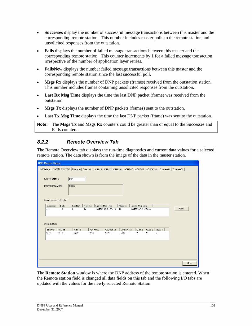
DNP3 User and Reference Manual December 31, 2007
102
Successes display the number of successful message transactions between this master and the corresponding remote station. This number includes master polls to the remote station and unsolicited responses from the outstation.
Fails displays the number of failed message transactions between this master and the corresponding remote station. This counter increments by 1 for a failed message transaction irrespective of the number of application layer retries.
FailsNew displays the number failed message transactions between this master and the corresponding remote station since the last successful poll.
Msgs Rx displays the number of DNP packets (frames) received from the outstation station. This number includes frames containing unsolicited responses from the outstation.
Last Rx Msg Time displays the time the last DNP packet (frame) was received from the outstation.
Msgs Tx displays the number of DNP packets (frames) sent to the outstation.
Last Tx Msg Time displays the time the last DNP packet (frame) was sent to the outstation.
Note: The Msgs Tx and Msgs Rx counters could be greater than or equal to the Successes and Fails counters.
8.2.2 Remote Overview Tab
The Remote Overview tab displays the run-time diagnostics and current data values for a selected remote station. The data shown is from the image of the data in the master station.
The Remote Station window is where the DNP address of the remote station is entered. When the Remote station field is changed all data fields on this tab and the following I/O tabs are updated with the values for the newly selected Remote Station.

DNP3 User and Reference Manual December 31, 2007
103
The Internal Indications window displays the current state of the DNP internal indications (IIN) flags for the selected remote station. For a detailed description of the IIN flags see the section 2.1.1.1 of this manual.
The Communication Statistics window displays communication statistics for the remote station selected. The statistics counters increment whenever a new DNP message is sent or received, and roll over after 65535 messages. The following statistics are displayed.
Successes displays the number of successful messages received in response to master polls sent to the station. This number includes unsolicited responses from the outstation.
Fails displays the number of failed or no responses to master polls sent to the outstation.
FailsNew displays the number failed or no responses to master polls sent to the outstation since the last successful poll.
Msgs Rx displays the number of messages received from the outstation station. This number includes unsolicited responses from the outstation.
Last Rx Msg Time displays the time the last message was received from the outstation.
Msgs Tx displays the number of messages sent to the outstation station.
Last Tx Msg Time displays the time the last message was sent to the outstation.
Click Reset to reset the counters to zero.
Event Buffers shows the number of events in each type of event buffer and the allocated buffer size. The buffers shown are for binary inputs, 16-bit analog inputs, 32-bit analog inputs, Floating point analog inputs, 16-bit counter inputs, and 32-bit counter inputs, and Class 1, 2, and 3 events.
The Event Buffers window displays the number of events in each type of event buffer and the allocated buffer size for the selected remote station. The event buffers displayed are:
Binary In (binary inputs)
AIN-16 (16-bit analog inputs)
AIN-32 (32-bit analog inputs)
AIN-Float (floating point analog inputs)
Counter-16 (16-bit counter inputs)
Counter-32 (32-bit counter inputs)
Class 1 (class 1 events)
Class 2 (class 2 events)
Class 3 (class 3 events)
Note: Due to a limitation of the DNP3 protocol, an Unsolicited message from an outstation is not capable of including information stating which data class generated the message. As a result, all Unsolicited events when received by the master will be counted as Class 1 events. Events which are polled by the master, however, do contain class information and will be counted in the Event Buffer for the appropriate class.

DNP3 User and Reference Manual December 31, 2007
104
8.2.3 Remote Point Status Tabs
The point status tabs show the state of each point of the selected type in the remote station selected on the Remote Overview tab. The values shown are from the image of the remote station in the master station.
Note: Class 0 polling of an outstation must be enabled in the master in order to allow that outstation’s DNP points to be listed on these tabs. This is the only way for the master to retrieve a complete list of all points in an outstation.
The example below shows the appearance of the Binary In tab.
The DNP Address column shows the DNP address of the point.
The Modbus Address column shows the Modbus register address of the point. This is only relevant for points that have an address mapping in the master station. For points that have an address mapping, this will show the Modbus register address of the point. For points which do not have an address mapping, this will show ‘---‘.
The Value column shows the value of the point. Binary points are shows as OFF or ON. Numeric points show the numeric value of the point.

DNP3 User and Reference Manual December 31, 2007
105
9 DNP Master Device Profile Document
DNP v3.00
DEVICE PROFILE DOCUMENT
Vendor Name: Control Microsystems Inc.
Device Name: SCADAPack controllers
Highest DNP Level Supported: For Requests 2 For Responses 2
Device Function:
Master Slave
Notable objects, functions, and/or qualifiers supported in addition to the Highest DNP Levels Supported (the complete list is described in the attached table):
Function code 14 (warm restart)
Function code 20 (Enable Unsolicited Messages) for class 1, 2, 3 objects only.
Function code 21 (Disable Unsolicited Messages) for class 1, 2, 3 objects only.
Object 41, variation 1 (32-bit analog output block)
Maximum Data Link Frame Size (octets): Transmitted 292 Received (must be 292)
Maximum Application Fragment Size (octets): Transmitted 2048 Received 2048

DNP3 User and Reference Manual December 31, 2007
106
Maximum Data Link Re-tries: None Fixed at
Configurable, range 0 to 255
Maximum Application Layer Re-tries: None
Configurable, range 0 to 255
Requires Data Link Layer Confirmation: Never Always Sometimes If 'Sometimes', when?
Configurable for Always or Never
Requires Application Layer Confirmation: Never Always (not recommended) When reporting Event Data (Slave devices only) When sending multi-fragment responses (Slave devices only) Sometimes If 'Sometimes', when? ______________________________________________
Configurable for always or only when Reporting Event Data and Unsolicited Messages
Timeouts while waiting for:
Data Link Confirm None Fixed at _________ Variable Configurable
Complete Appl. Fragment None Fixed at _________ Variable Configurable
Application Confirm None Fixed at _________ Variable Configurable
Complete Appl. Response None Fixed at _________ Variable Configurable Others __________________________________________________________________________
Sends/Executes Control Operations:
WRITE Binary Outputs Never Always Sometimes Configurable
SELECT/OPERATE Never Always Sometimes Configurable
DIRECT OPERATE Never Always Sometimes Configurable
DIRECT OPERATE - NO ACK Never Always Sometimes Configurable
Count > 1 Never Always Sometimes Configurable

DNP3 User and Reference Manual December 31, 2007
107
Pulse On Never Always Sometimes Configurable
Pulse Off Never Always Sometimes Configurable
Latch On Never Always Sometimes Configurable
Latch Off Never Always Sometimes Configurable
Queue Never Always Sometimes Configurable
Clear Queue Never Always Sometimes Configurable
FILL OUT THE FOLLOWING ITEM FOR MASTER DEVICES ONLY:
Expects Binary Input Change Events:
Either time-tagged or non-time-tagged for a single event Both time-tagged and non-time-tagged for a single event Configurable (attach explanation)
FILL OUT THE FOLLOWING ITEMS FOR SLAVE DEVICES ONLY:
Reports Binary Input Change Events when no specific variation requested: Never Only time-tagged Only non-time-tagged Configurable to send both, one or the other (attach explanation)
Reports time-tagged Binary Input Change Events when no specific variation requested: Never Binary Input Change With Time Binary Input Change With Relative Time Configurable (attach explanation)
Sends Unsolicited Responses: Never Configurable by class Only certain objects Sometimes (attach explanation)
ENABLE/DISABLE UNSOLICITED
Sends Static Data in Unsolicited Responses: Never When Device Restarts When Status Flags Change No other options are permitted.
Default Counter Object/Variation: No Counters Reported Configurable (attach explanation) Default Object 20 Default Variation 05
Counters Roll Over at: No Counters Reported Configurable (attach explanation) 16 Bits 32 Bits

DNP3 User and Reference Manual December 31, 2007
108
Point-by-point list attached 16 Bits for 16-bit counters 32 Bits for 32-bit counters Point-by-point list attached
Sends Multi-Fragment Responses: Yes No

DNP3 User and Reference Manual December 31, 2007
109
DNP V3.00 DEVICE PROFILE DOCUMENT IMPLEMENTATION OBJECT This table describes the objects, function codes and qualifiers used in the device:
OBJECT
REQUEST
(slave must parse)
RESPONSE
(master must parse) Obj
Var
Description Func
Codes (dec)
Qual Codes (hex)
Func Codes
Qual
Codes (hex)
1
0
Binary Input - All Variations 1 06
1
1
Binary Input 129, 130
00, 01
1
2
Binary Input with Status 129, 130
00, 01
2
0
Binary Input Change - All Variations 1 06,07,08
2
1
Binary Input Change without Time 1 06,07,08 129, 130
17, 28
2
2
Binary Input Change with Time 1 06,07,08 129, 130
17, 28
2
3
Binary Input Change with Relative Time 1 06,07,08 129, 130
17, 28
10
0
Binary Output - All Variations 1 06
10
1
Binary Output
10
2
Binary Output Status 129, 130
00, 01
12
0
Control Block - All Variations
12
1
Control Relay Output Block 3, 4, 5,
6 17, 28 129
echo of request
12
2
Pattern Control Block
12
3
Pattern Mask
20
0
Binary Counter - All Variations 1, 7, 8,
9, 10 06
20
1
32-Bit Binary Counter 129, 130
00, 01
20
2
16-Bit Binary Counter 129, 130
00, 01
20
3
32-Bit Delta Counter
20
4
16-Bit Delta Counter
20
5
32-Bit Binary Counter without Flag 129, 130
00, 01
20
6
16-Bit Binary Counter without Flag 129, 130
00, 01
20
7
32-Bit Delta Counter without Flag

DNP3 User and Reference Manual December 31, 2007
110
DNP V3.00 DEVICE PROFILE DOCUMENT IMPLEMENTATION OBJECT This table describes the objects, function codes and qualifiers used in the device:
OBJECT
REQUEST
(slave must parse)
RESPONSE
(master must parse) Obj
Var
Description Func
Codes (dec)
Qual Codes (hex)
Func Codes
Qual
Codes (hex)
20
8
16-Bit Delta Counter without Flag
21
0
Frozen Counter - All Variations 1 06
21
1
32-Bit Frozen Counter 129, 130
00, 01
21
2
16-Bit Frozen Counter 129, 130
00, 01
21
3
32-Bit Frozen Delta Counter
21
4
16-Bit Frozen Delta Counter
21
5
32-Bit Frozen Counter with Time of Freeze
21
6
16-Bit Frozen Counter with Time of Freeze
21
7
32-Bit Frozen Delta Counter with Time of Freeze
21
8
16-Bit Frozen Delta Counter with Time of Freeze
21
9
32-Bit Frozen Counter without Flag 129, 130
00, 01
21
10
16-Bit Frozen Counter without Flag 129, 130
00, 01
21
11
32-Bit Frozen Delta Counter without Flag
21
12
16-Bit Frozen Delta Counter without Flag
22
0
Counter Change Event - All Variations 1 06,07,08
22
1
32-Bit Counter Change Event without Time 129, 130
17, 28
22
2
16-Bit Counter Change Event without Time 129, 130
17, 28
22
3
32-Bit Delta Counter Change Event without Time
22
4
16-Bit Delta Counter Change Event without Time
22
5
32-Bit Counter Change Event with Time
22
6
16-Bit Counter Change Event with Time
22
7
32-Bit Delta Counter Change Event with Time
22
8
16-Bit Delta Counter Change Event with Time

DNP3 User and Reference Manual December 31, 2007
111
DNP V3.00 DEVICE PROFILE DOCUMENT IMPLEMENTATION OBJECT This table describes the objects, function codes and qualifiers used in the device:
OBJECT
REQUEST
(slave must parse)
RESPONSE
(master must parse) Obj
Var
Description Func
Codes (dec)
Qual Codes (hex)
Func Codes
Qual
Codes (hex)
23
0
Frozen Counter Event - All Variations
23
1
32-Bit Frozen Counter Event without Time
23
2
16-Bit Frozen Counter Event without Time
23
3
32-Bit Frozen Delta Counter Event without Time
23
4
16-Bit Frozen Delta Counter Event without Time
23
5
32-Bit Frozen Counter Event with Time
23
6
16-Bit Frozen Counter Event with Time
23
7
32-Bit Frozen Delta Counter Event with Time
23
8
16-Bit Frozen Delta Counter Event with Time
30
0
Analog Input - All Variations 1 06
30
1
32-Bit Analog Input 129, 130
00, 01
30
2
16-Bit Analog Input 129, 130
00, 01
30
3
32-Bit Analog Input without Flag 129, 130
00, 01
30
4
16-Bit Analog Input without Flag 129, 130
00, 01
30
5
Short Floating Point Analog Input 129, 130
00, 01
31
0
Frozen Analog Input - All Variations
31
1
32-Bit Frozen Analog Input
31
2
16-Bit Frozen Analog Input
31
3
32-Bit Frozen Analog Input with Time of Freeze
31
4
16-Bit Frozen Analog Input with Time of Freeze
31
5
32-Bit Frozen Analog Input without Flag
31
6
16-Bit Frozen Analog Input without Flag
32
0
Analog Change Event - All Variations 1 06,07,08
32
1
32-Bit Analog Change Event without Time 129,130
17,28
32
2
16-Bit Analog Change Event without Time 129,130
17,28

DNP3 User and Reference Manual December 31, 2007
112
DNP V3.00 DEVICE PROFILE DOCUMENT IMPLEMENTATION OBJECT This table describes the objects, function codes and qualifiers used in the device:
OBJECT
REQUEST
(slave must parse)
RESPONSE
(master must parse) Obj
Var
Description Func
Codes (dec)
Qual Codes (hex)
Func Codes
Qual
Codes (hex)
32
3
32-Bit Analog Change Event with Time 129,130
17,28
32
4
16-Bit Analog Change Event with Time 129,130
17,28
32
5
Short Floating Point Analog Change Event without Time
129,130 17,28
33
0
Frozen Analog Event - All Variations
33
1
32-Bit Frozen Analog Event without Time
33
2
16-Bit Frozen Analog Event without Time
33
3
32-Bit Frozen Analog Event with Time
33
4
16-Bit Frozen Analog Event with Time
40
0
Analog Output Status - All Variations 1 06
40
1
32-Bit Analog Output Status 129, 130
00, 01
40
2
16-Bit Analog Output Status 129, 130
00, 01
40
3
Short Floating Point Analog Output Status 129, 130
00, 01
41
0
Analog Output Block - All Variations
41
1
32-Bit Analog Output Block 3, 4, 5,
6 17, 28 129
echo of request
41
2
16-Bit Analog Output Block 3, 4, 5,
6 17, 28 129
echo of request
41
3
Short Floating Point Analog Output Block 3, 4, 5,
6 17, 28 129
echo of request
50
0
Time and Date - All Variations
50
1
Time and Date 2 (see
4.14) 07 where quantity = 1
50
2
Time and Date with Interval
51
0
Time and Date CTO - All Variations
51
1
Time and Date CTO 129, 130
07, quantity=1
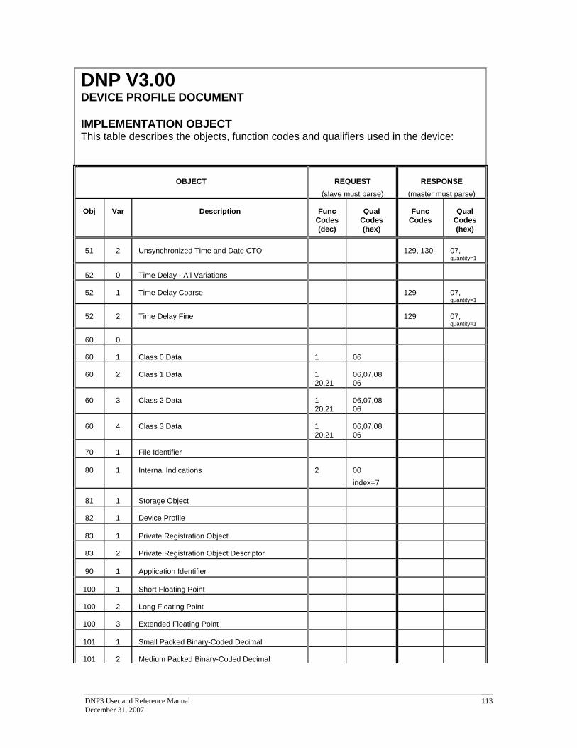
DNP3 User and Reference Manual December 31, 2007
113
DNP V3.00 DEVICE PROFILE DOCUMENT IMPLEMENTATION OBJECT This table describes the objects, function codes and qualifiers used in the device:
OBJECT
REQUEST
(slave must parse)
RESPONSE
(master must parse) Obj
Var
Description Func
Codes (dec)
Qual Codes (hex)
Func Codes
Qual
Codes (hex)
51
2
Unsynchronized Time and Date CTO 129, 130
07, quantity=1
52
0
Time Delay - All Variations
52
1
Time Delay Coarse 129
07, quantity=1
52
2
Time Delay Fine 129
07, quantity=1
60
0
60
1
Class 0 Data 1 06
60
2
Class 1 Data 1
20,21 06,07,08 06
60
3
Class 2 Data 1
20,21 06,07,08 06
60
4
Class 3 Data 1
20,21 06,07,08 06
70
1
File Identifier
80
1
Internal Indications 2 00
index=7
81
1
Storage Object
82
1
Device Profile
83
1
Private Registration Object
83
2
Private Registration Object Descriptor
90
1
Application Identifier
100
1
Short Floating Point
100
2
Long Floating Point
100
3
Extended Floating Point
101
1
Small Packed Binary-Coded Decimal
101
2
Medium Packed Binary-Coded Decimal

DNP3 User and Reference Manual December 31, 2007
114
DNP V3.00 DEVICE PROFILE DOCUMENT IMPLEMENTATION OBJECT This table describes the objects, function codes and qualifiers used in the device:
OBJECT
REQUEST
(slave must parse)
RESPONSE
(master must parse) Obj
Var
Description Func
Codes (dec)
Qual Codes (hex)
Func Codes
Qual
Codes (hex)
101
3
Large Packed Binary-Coded Decimal
No Object 13
No Object 14
No Object 23
(see 4.14)
DNP V3.00 TIME SYNCHRONISATION PARAMETERS This table describes the worst-case time parameters relating to time synchronisation, as required by DNP Level 2 Certification Procedure section 8.7
PARAMETER
VALUE
Time base drift +/- 1 minute/month at 25°C
+1 / -3 minutes/month 0 to 50°C
Time base drift over a 10-minute interval +/- 14 milliseconds at 25°C
+14 / -42 milliseconds 0 to 50°C
Maximum delay measurement error +/- 100 milliseconds
Maximum internal time reference error when set from the protocol
+/- 100 milliseconds
Maximum response time 100 milliseconds

DNP3 User and Reference Manual December 31, 2007
115
10 DNP Slave Device Profile Document
DNP v3.00
DEVICE PROFILE DOCUMENT
Vendor Name: Control Microsystems Inc.
Device Name: SCADAPack controllers
Highest DNP Level Supported: For Requests 2 For Responses 2
Device Function:
Master Slave
Notable objects, functions, and/or qualifiers supported in addition to the Highest DNP Levels Supported (the complete list is described in the attached table): Function code 14 (warm restart) Function code 20 (Enable Unsolicited Messages) for class 1, 2, 3 objects only. Function code 21 (Disable Unsolicited Messages) for class 1, 2, 3 objects only. Object 41, variation 1 (32-bit analog output block)
Maximum Data Link Frame Size (octets): Transmitted 292 Received (must be 292)
Maximum Application Fragment Size (octets): Transmitted 2048 Received 2048

DNP3 User and Reference Manual December 31, 2007
116
Maximum Data Link Re-tries: None Fixed at
Configurable, range 0 to 255
Maximum Application Layer Re-tries: None
Configurable, range 0 to 255
Requires Data Link Layer Confirmation: Never Always Sometimes If 'Sometimes', when?
Configurable for Always or Never
Requires Application Layer Confirmation: Never Always (not recommended) When reporting Event Data (Slave devices only) When sending multi-fragment responses (Slave devices only) Sometimes If 'Sometimes', when? ______________________________________________
Configurable for always or only when Reporting Event Data and Unsolicited Messages
Timeouts while waiting for:
Data Link Confirm None Fixed at _________ Variable Configurable
Complete Appl. Fragment None Fixed at _________ Variable Configurable
Application Confirm None Fixed at _________ Variable Configurable
Complete Appl. Response None Fixed at _________ Variable Configurable Others __________________________________________________________________________
Sends/Executes Control Operations:
WRITE Binary Outputs Never Always Sometimes Configurable
SELECT/OPERATE Never Always Sometimes Configurable
DIRECT OPERATE Never Always Sometimes Configurable
DIRECT OPERATE - NO ACK Never Always Sometimes Configurable

DNP3 User and Reference Manual December 31, 2007
117
Count > 1 Never Always Sometimes Configurable
Pulse On Never Always Sometimes Configurable
Pulse Off Never Always Sometimes Configurable
Latch On Never Always Sometimes Configurable
Latch Off Never Always Sometimes Configurable
Queue Never Always Sometimes Configurable
Clear Queue Never Always Sometimes Configurable FILL OUT THE FOLLOWING ITEM FOR MASTER DEVICES ONLY:
Expects Binary Input Change Events: Either time-tagged or non-time-tagged for a single event Both time-tagged and non-time-tagged for a single event Configurable (attach explanation)
FILL OUT THE FOLLOWING ITEMS FOR SLAVE DEVICES ONLY:
Reports Binary Input Change Events when no specific variation requested: Never Only time-tagged
Only non-time-tagged Configurable to send both, one or the other (attach explanation)
Reports time-tagged Binary Input Change Events when no specific variation requested:
Never Binary Input Change With Time Binary Input Change With Relative Time Configurable (attach explanation)
Sends Unsolicited Responses: Never
Configurable by class Only certain objects Sometimes (attach explanation)
ENABLE/DISABLE UNSOLICITED
Sends Static Data in Unsolicited Responses:
Never When Device Restarts When Status Flags Change No other options are permitted.
Default Counter Object/Variation: No Counters Reported Configurable (attach explanation)
Default Object 20
Counters Roll Over at: No Counters Reported Configurable (attach explanation) 16 Bits

DNP3 User and Reference Manual December 31, 2007
118
Default Variation 05 Point-by-point list attached
32 Bits
16 Bits for 16-bit counters 32 Bits for 32-bit counters Point-by-point list attached
Sends Multi-Fragment Responses: Yes No

DNP3 User and Reference Manual December 31, 2007
119
DNP V3.00 DEVICE PROFILE DOCUMENT IMPLEMENTATION OBJECT This table describes the objects, function codes and qualifiers used in the device:
OBJECT
REQUEST
(slave must parse)
RESPONSE
(master must parse) Obj
Var
Description Func
Codes (dec)
Qual Codes (hex)
Func Codes
Qual
Codes (hex)
1
0
Binary Input - All Variations 1 06
1
1
Binary Input 129, 130
00, 01
1
2
Binary Input with Status 129, 130
00, 01
2
0
Binary Input Change - All Variations 1 06,07,08
2
1
Binary Input Change without Time 1 06,07,08 129, 130
17, 28
2
2
Binary Input Change with Time 1 06,07,08 129, 130
17, 28
2
3
Binary Input Change with Relative Time 1 06,07,08 129, 130
17, 28
10
0
Binary Output - All Variations 1 06
10
1
Binary Output
10
2
Binary Output Status 129, 130
00, 01
12
0
Control Block - All Variations
12
1
Control Relay Output Block 3, 4, 5,
6 17, 28 129
echo of request
12
2
Pattern Control Block
12
3
Pattern Mask
20
0
Binary Counter - All Variations 1, 7, 8,
9, 10 06
20
1
32-Bit Binary Counter 129, 130
00, 01
20
2
16-Bit Binary Counter 129, 130
00, 01
20
3
32-Bit Delta Counter
20
4
16-Bit Delta Counter
20
5
32-Bit Binary Counter without Flag 129, 130
00, 01
20
6
16-Bit Binary Counter without Flag 129, 130
00, 01
20
7
32-Bit Delta Counter without Flag

DNP3 User and Reference Manual December 31, 2007
120
DNP V3.00 DEVICE PROFILE DOCUMENT IMPLEMENTATION OBJECT This table describes the objects, function codes and qualifiers used in the device:
OBJECT
REQUEST
(slave must parse)
RESPONSE
(master must parse) Obj
Var
Description Func
Codes (dec)
Qual Codes (hex)
Func Codes
Qual
Codes (hex)
20
8
16-Bit Delta Counter without Flag
21
0
Frozen Counter - All Variations 1 06
21
1
32-Bit Frozen Counter 129, 130
00, 01
21
2
16-Bit Frozen Counter 129, 130
00, 01
21
3
32-Bit Frozen Delta Counter
21
4
16-Bit Frozen Delta Counter
21
5
32-Bit Frozen Counter with Time of Freeze
21
6
16-Bit Frozen Counter with Time of Freeze
21
7
32-Bit Frozen Delta Counter with Time of Freeze
21
8
16-Bit Frozen Delta Counter with Time of Freeze
21
9
32-Bit Frozen Counter without Flag 129, 130
00, 01
21
10
16-Bit Frozen Counter without Flag 129, 130
00, 01
21
11
32-Bit Frozen Delta Counter without Flag
21
12
16-Bit Frozen Delta Counter without Flag
22
0
Counter Change Event - All Variations 1 06,07,08
22
1
32-Bit Counter Change Event without Time 129, 130
17, 28
22
2
16-Bit Counter Change Event without Time 129, 130
17, 28
22
3
32-Bit Delta Counter Change Event without Time
22
4
16-Bit Delta Counter Change Event without Time
22
5
32-Bit Counter Change Event with Time
22
6
16-Bit Counter Change Event with Time
22
7
32-Bit Delta Counter Change Event with Time
22
8
16-Bit Delta Counter Change Event with Time

DNP3 User and Reference Manual December 31, 2007
121
DNP V3.00 DEVICE PROFILE DOCUMENT IMPLEMENTATION OBJECT This table describes the objects, function codes and qualifiers used in the device:
OBJECT
REQUEST
(slave must parse)
RESPONSE
(master must parse) Obj
Var
Description Func
Codes (dec)
Qual Codes (hex)
Func Codes
Qual
Codes (hex)
23
0
Frozen Counter Event - All Variations
23
1
32-Bit Frozen Counter Event without Time
23
2
16-Bit Frozen Counter Event without Time
23
3
32-Bit Frozen Delta Counter Event without Time
23
4
16-Bit Frozen Delta Counter Event without Time
23
5
32-Bit Frozen Counter Event with Time
23
6
16-Bit Frozen Counter Event with Time
23
7
32-Bit Frozen Delta Counter Event with Time
23
8
16-Bit Frozen Delta Counter Event with Time
30
0
Analog Input - All Variations 1 06
30
1
32-Bit Analog Input 129, 130
00, 01
30
2
16-Bit Analog Input 129, 130
00, 01
30
3
32-Bit Analog Input without Flag 129, 130
00, 01
30
4
16-Bit Analog Input without Flag 129, 130
00, 01
30
5
Short Floating Point Analog Input 129, 130
00, 01
31
0
Frozen Analog Input - All Variations
31
1
32-Bit Frozen Analog Input
31
2
16-Bit Frozen Analog Input
31
3
32-Bit Frozen Analog Input with Time of Freeze
31
4
16-Bit Frozen Analog Input with Time of Freeze
31
5
32-Bit Frozen Analog Input without Flag
31
6
16-Bit Frozen Analog Input without Flag
32
0
Analog Change Event - All Variations 1 06,07,08
32
1
32-Bit Analog Change Event without Time 129,130
17,28
32
2
16-Bit Analog Change Event without Time 129,130
17,28

DNP3 User and Reference Manual December 31, 2007
122
DNP V3.00 DEVICE PROFILE DOCUMENT IMPLEMENTATION OBJECT This table describes the objects, function codes and qualifiers used in the device:
OBJECT
REQUEST
(slave must parse)
RESPONSE
(master must parse) Obj
Var
Description Func
Codes (dec)
Qual Codes (hex)
Func Codes
Qual
Codes (hex)
32
3
32-Bit Analog Change Event with Time 129,130
17,28
32
4
16-Bit Analog Change Event with Time 129,130
17,28
32
5
Short Floating Point Analog Change Event without Time
129,130 17,28
33
0
Frozen Analog Event - All Variations
33
1
32-Bit Frozen Analog Event without Time
33
2
16-Bit Frozen Analog Event without Time
33
3
32-Bit Frozen Analog Event with Time
33
4
16-Bit Frozen Analog Event with Time
40
0
Analog Output Status - All Variations 1 06
40
1
32-Bit Analog Output Status 129, 130
00, 01
40
2
16-Bit Analog Output Status 129, 130
00, 01
40
3
Short Floating Point Analog Output Status 129, 130
00, 01
41
0
Analog Output Block - All Variations
41
1
32-Bit Analog Output Block 3, 4, 5,
6 17, 28 129
echo of request
41
2
16-Bit Analog Output Block 3, 4, 5,
6 17, 28 129
echo of request
41
3
Short Floating Point Analog Output Block 3, 4, 5,
6 17, 28 129
echo of request
50
0
Time and Date - All Variations
50
1
Time and Date 2 (see
4.14) 07 where quantity = 1
50
2
Time and Date with Interval
51
0
Time and Date CTO - All Variations
51
1
Time and Date CTO 129, 130
07, quantity=1

DNP3 User and Reference Manual December 31, 2007
123
DNP V3.00 DEVICE PROFILE DOCUMENT IMPLEMENTATION OBJECT This table describes the objects, function codes and qualifiers used in the device:
OBJECT
REQUEST
(slave must parse)
RESPONSE
(master must parse) Obj
Var
Description Func
Codes (dec)
Qual Codes (hex)
Func Codes
Qual
Codes (hex)
51
2
Unsynchronized Time and Date CTO 129, 130
07, quantity=1
52
0
Time Delay - All Variations
52
1
Time Delay Coarse 129
07, quantity=1
52
2
Time Delay Fine 129
07, quantity=1
60
0
60
1
Class 0 Data 1 06
60
2
Class 1 Data 1
20,21 06,07,08 06
60
3
Class 2 Data 1
20,21 06,07,08 06
60
4
Class 3 Data 1
20,21 06,07,08 06
70
1
File Identifier
80
1
Internal Indications 2 00
index=7
81
1
Storage Object
82
1
Device Profile
83
1
Private Registration Object
83
2
Private Registration Object Descriptor
90
1
Application Identifier
100
1
Short Floating Point
100
2
Long Floating Point
100
3
Extended Floating Point
101
1
Small Packed Binary-Coded Decimal
101
2
Medium Packed Binary-Coded Decimal

DNP3 User and Reference Manual December 31, 2007
124
DNP V3.00 DEVICE PROFILE DOCUMENT IMPLEMENTATION OBJECT This table describes the objects, function codes and qualifiers used in the device:
OBJECT
REQUEST
(slave must parse)
RESPONSE
(master must parse) Obj
Var
Description Func
Codes (dec)
Qual Codes (hex)
Func Codes
Qual
Codes (hex)
101
3
Large Packed Binary-Coded Decimal
No Object 13
No Object 14
No Object 23
(see 4.14)
DNP V3.00 TIME SYNCHRONISATION PARAMETERS This table describes the worst-case time parameters relating to time synchronization, as required by DNP Level 2 Certification Procedure section 8.7
PARAMETER
VALUE
Time base drift +/- 1 minute/month at 25°C
+1 / -3 minutes/month 0 to 50°C
Time base drift over a 10-minute interval +/- 14 milliseconds at 25°C
+14 / -42 milliseconds 0 to 50°C
Maximum delay measurement error +/- 100 milliseconds
Maximum internal time reference error when set from the protocol
+/- 100 milliseconds
Maximum response time 100 milliseconds