Embed Size (px)
Citation preview

DNP3 Slave Protocol

Documentation for Cybectec part number P-SSPR-0201
The information in this document applies to software version 3.0 or later and is subject to change without notice.
Quebec City
730 Commerciale Street Suite 200 Saint-Jean-Chrysostome, Quebec Canada G6Z 2C5 Phone: 418-834-0009 Fax: 514-227-5256
Montreal
1290 St. Denis Street Suite 400 Montreal, Quebec Canada H2X 3J7 Phone: 514-845-6195 Fax: 514-227-5256

Revision History
Version Date Author Comments
3 2007-02-27 Johanne Lavallée Cooper integration, no major changes for version 4.
2 2007-01-15 Jonathan Fortier Added support for Qualifier Code 0x27.
1 2006-01-20 Rémi Dutil No major changes with respect to version 2.0.


Contents
1. Introduction ............................................................................................................................. 1 1.1 References............................................................................................................................ 1 1.2 Document Overview .............................................................................................................. 1 1.3 Glossary ............................................................................................................................... 1
2. Interoperability ........................................................................................................................ 2 2.1 Implementation Restrictions and Warnings .............................................................................. 2 2.2 DNP3 Device Profile ............................................................................................................... 2 2.3 Implementation Table............................................................................................................ 6
3. Configuration Settings ........................................................................................................... 11 3.1 General Settings.................................................................................................................. 11 3.2 Default Variation Settings..................................................................................................... 16 3.3 Switched Connection Settings ............................................................................................... 17 3.4 Switched Connection Schedule Settings ................................................................................. 18 3.5 Analog Input Settings .......................................................................................................... 18 3.6 Binary Input Settings ........................................................................................................... 20 3.7 Counter Input Settings......................................................................................................... 21 3.8 Analog Output Settings ........................................................................................................ 23 3.9 Binary Output Settings ......................................................................................................... 25 3.10 Comma-Separated Values File Format ................................................................................... 27
4. Multiple Instances.................................................................................................................. 28 5. Operations.............................................................................................................................. 29
5.1 Startup Sequence ................................................................................................................ 29 5.2 DNP Task Management........................................................................................................ 29 5.3 Switched Mode.................................................................................................................... 29 5.4 Clock Synchronization .......................................................................................................... 30 5.5 Unsolicited Reports.............................................................................................................. 30
5.5.1 Sending Unsolicited Responses ............................................................................... 31 5.5.2 Event Class Priorities ............................................................................................. 31 5.5.3 Event Queuing vs. System Startup and Link Reset.................................................... 31
5.6 Output Control Operations.................................................................................................... 32 5.6.1 Command Confirmation: real and simulated............................................................. 32 5.6.2 Analog Output Specific........................................................................................... 32 5.6.3 Binary Output Specific ........................................................................................... 32
5.6.3.1 TRIP/CLOSE operations using two pulse points........................................ 33 5.7 Cold and Warm Restart ........................................................................................................ 33
5.7.1 Warm Restart Behavior .......................................................................................... 33 5.7.2 Cold Restart Behavior ............................................................................................ 34
5.8 Data Object Management..................................................................................................... 34 5.8.1 Time-Tagging ....................................................................................................... 34 5.8.2 Analog Inputs ....................................................................................................... 34
5.8.2.1 Analog input event generation ............................................................... 35 5.8.2.2 Analog input reporting deadband ........................................................... 35
5.8.3 Binary Inputs ........................................................................................................ 36 5.8.3.1 Binary input event generation ................................................................ 36
5.8.4 Counter Inputs...................................................................................................... 37 5.8.4.1 Counter input event generation.............................................................. 37 5.8.4.2 Frozen counter input event generation.................................................... 38
5.8.5 Analog Outputs ..................................................................................................... 38
DNP3 SLAVE PROTOCOL I

5.8.5.1 Analog output control state.................................................................... 39 5.8.5.2 Analog output event generation ............................................................. 39
5.8.6 Binary Outputs...................................................................................................... 40 5.8.6.1 Binary output control state .................................................................... 40 5.8.6.2 Binary output event generation .............................................................. 40
5.8.7 Generated Binary Inputs ........................................................................................ 41 6. Diagnostics..............................................................................................................................42
6.1 Log Entries ......................................................................................................................... 42 6.2 Statistics Tables .................................................................................................................. 42
6.2.1 Page 1 - Configuration........................................................................................... 42 6.2.2 Page 2 - Operations and Protocol Layers Statistics ................................................... 45 6.2.3 Page 3 – Switched Connections .............................................................................. 47
6.3 Real-Time Traces ................................................................................................................ 49 6.4 SNMP Traps ........................................................................................................................ 50
6.4.1 Link Up/Down Trap ............................................................................................... 50
II DNP3 SLAVE PROTOCOL

Tables Table 2-1Device Profile ................................................................................................................... 5 Table 2-2Implementation Table ................................................................................................... 10 Table 3-3General Settings............................................................................................................. 15 Table 3-4Default Variation Settings.............................................................................................. 17 Table 3-5Switched Connection Settings ....................................................................................... 18 Table 3-6Switched Connection Schedule Settings........................................................................ 18 Table 3-7Analog Input Settings .................................................................................................... 20 Table 3-8Binary Input Settings..................................................................................................... 21 Table 3-9Counter Input Settings .................................................................................................. 23 Table 3-10Analog Output Settings................................................................................................ 25 Table 3-11Binary Output Settings ................................................................................................ 26 Table 5-1Situations in which an outgoing connection is initiated with the remote master......... 30 Table 5-2Translation of the RTDX status bits to DNP flags for analog inputs.............................. 35 Table 5-3Translation of the RTDX status bits to DNP flags for binary inputs .............................. 36 Table 5-4Translation of the RTDX status bits to DNP flags for counter inputs ............................ 37 Table 5-5Translation of the RTDX status bits to DNP flags for analog outputs ........................... 39 Table 5-6Translation of the RTDX status bits to DNP flags for binary outputs ............................ 40 Table 5-7Generated Binary Inputs................................................................................................ 41 Table 6-1Log Entries ..................................................................................................................... 42 Table 6-2Configuration Page ........................................................................................................ 44 Table 6-3Operations and Protocol Layer Statistics Page.............................................................. 47 Table 6-4Switched Connections Page........................................................................................... 48 Table 6-5Trace Messages.............................................................................................................. 50
DNP3 SLAVE PROTOCOL III


1. Introduction This document describes the implementation of the DNP3 Slave in Cybectec’s SMP gateway architecture. The DNP3 slave is used to report information on I/O points of different RTUs to a DNP3 master station. This is done through standard asynchronous serial links in either point-to-point or multi-drop configurations, or on a standard network TCP/IP link.
The document has the following objectives:
Serve as a requirements specification to the protocol implementation team.
Serve as a requirements specification for the “Protocol Test Instruction Manual”.
Allow clients to validate protocol features and limitations, in order to ensure that the implementation fulfills their requirements.
Remain as the final protocol implementation documentation, after appropriate updates following implementation and testing.
1.1 References
The DNP3 Slave implementation is based on the following protocol specifications:
DNP3 Data Link Layer (P009-0PD.DL), Harris Corporation;
DNP3 Transport Functions (P009-0PD.TF), Harris Corporation;
DNP3 Application Layer (P009-0PD.APP), Harris Corporation;
DNP3 Data Object Library (P009-0BL), Harris Corporation;
DNP3 Subset Definitions (P009-0IG.SUB), DNP Users Group.
It is absolutely essential that you read and understand the above-mentioned specifications before proceeding with the rest of this document. Everything discussed in this document will be meaningless unless you are fully familiar with the DNP3 protocol.
1.2 Document Overview
Chapter 2 This chapter deals with the DNP3 device’s profile and interoperability with other DNP3 devices. Its also enumerates those restrictions and protocol features that are not implemented by the current version of the DNP3 protocol component.
Chapter 3 This chapter documents all the configuration settings that are associated with the DNP3 slave component.
Chapter 4 This chapter describes all operations performed by the DNP3 slave component, including interactions with the RTDX component.
Chapter 5 This chapter describes all diagnostic information produced by the DNP3 slave component.
1.3 Glossary
DNP Distributed Network Protocol
IIN Internal Indication Flags
RTDX Real-Time Data Exchange
RTU Remote Terminal Unit
DNP3 SLAVE PROTOCOL 1
2. Interoperability The purpose of this chapter is to describe the implementation of the DNP3 protocol within the DNP3 Slave for Cybectec’s SMP gateway architecture.
In conjunction with chapter 3, the DNP 3.0 Basic 4 Document Set, and the DNP Subset Definitions Document, the present chapter provides complete information on how to communicate with the DNP3 Slave via the DNP3 protocol.
The implementation of the DNP3 slave is fully compliant with DNP3 Subset Definition Level 2, contains many Subset Level 3 features, and contains some functionality even beyond Subset Level 3.
2.1 Implementation Restrictions and Warnings
The following protocol and implementation restrictions must be understood:
All I/O points of a given type are defined with a unique index that must be less than 65535. No physical or logical addresses are used, since the index is the only way to identify an I/O point.
The data reported by the DNP3 slave is updated internally as fast as it is injected in the Real-Time Data Exchange component by the various master components. Obviously, when a master station is exchanging information with a DNP3 slave, the freshness of the data depends on the configuration (polling cycle/report by exception) of the master station, as well as on the polling cycle of the masters that are providing the data.
2.2 DNP3 Device Profile
The following table provides a “Device Profile Document” in the standard format defined in the DNP3 Subset Definitions Document. While it is referred to in DNP3 Subset Definitions as a “Document”, it is actually one of three components that make up an interoperability guide. The other two components are:
the Implementation Table, section 2.3;
a description of configuration methods, chapter 3.
Together, these three components make up a complete interoperability and configuration guide for the DNP3 slave component.
2 DNP3 SLAVE PROTOCOL
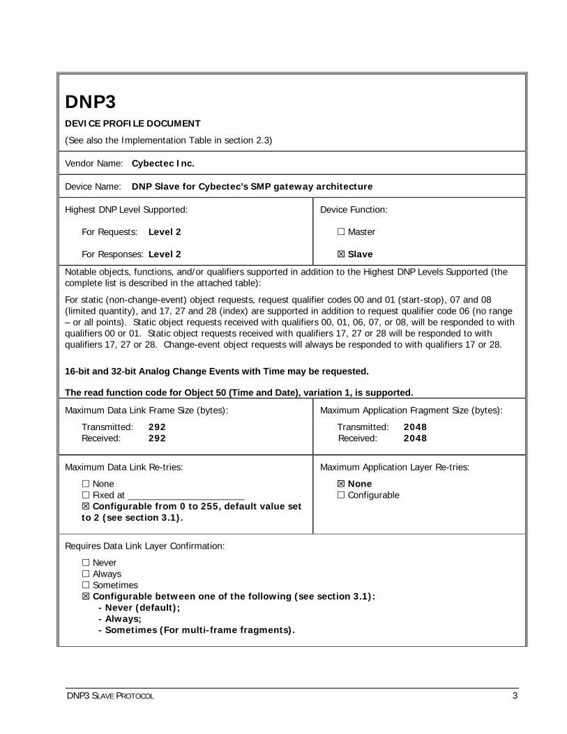
DNP3
DEVICE PROFILE DOCUMENT
(See also the Implementation Table in section 2.3)
Vendor Name: Cybectec Inc.
Device Name: DNP Slave for Cybectec’s SMP gateway architecture
Highest DNP Level Supported:
For Requests: Level 2
For Responses: Level 2
Device Function:
Master
Slave
Notable objects, functions, and/or qualifiers supported in addition to the Highest DNP Levels Supported (the complete list is described in the attached table):
For static (non-change-event) object requests, request qualifier codes 00 and 01 (start-stop), 07 and 08 (limited quantity), and 17, 27 and 28 (index) are supported in addition to request qualifier code 06 (no range – or all points). Static object requests received with qualifiers 00, 01, 06, 07, or 08, will be responded to with qualifiers 00 or 01. Static object requests received with qualifiers 17, 27 or 28 will be responded to with qualifiers 17, 27 or 28. Change-event object requests will always be responded to with qualifiers 17 or 28.
16-bit and 32-bit Analog Change Events with Time may be requested. The read function code for Object 50 (Time and Date), variation 1, is supported.
Maximum Data Link Frame Size (bytes):
Transmitted: 292 Received: 292
Maximum Application Fragment Size (bytes):
Transmitted: 2048 Received: 2048
Maximum Data Link Re-tries:
None Fixed at _______________________ Configurable from 0 to 255, default value set
to 2 (see section 3.1).
Maximum Application Layer Re-tries:
None Configurable
Requires Data Link Layer Confirmation:
Never Always Sometimes Configurable between one of the following (see section 3.1):
- Never (default); - Always; - Sometimes (For multi-frame fragments).
DNP3 SLAVE PROTOCOL 3
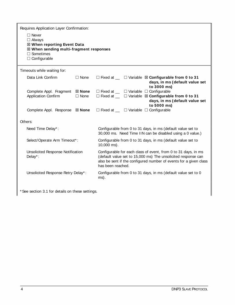
Requires Application Layer Confirmation:
Never Always When reporting Event Data When sending multi-fragment responses Sometimes Configurable
Timeouts while waiting for:
Data Link Confirm None Fixed at __ Variable Configurable from 0 to 31 days, in ms (default value set to 3000 ms)
Complete Appl. Fragment None Fixed at __ Variable Configurable Application Confirm None Fixed at __ Variable Configurable from 0 to 31
days, in ms (default value set to 5000 ms)
Complete Appl. Response None Fixed at __ Variable Configurable
Others:
Need Time Delay*: Configurable from 0 to 31 days, in ms (default value set to 30,000 ms. Need Time IIN can be disabled using a 0 value.)
Select/Operate Arm Timeout*: Configurable from 0 to 31 days, in ms (default value set to 10,000 ms).
Unsolicited Response Notification Delay*:
Configurable for each class of event, from 0 to 31 days, in ms (default value set to 15,000 ms) The unsolicited response can also be sent if the configured number of events for a given class has been reached.
Unsolicited Response Retry Delay*: Configurable from 0 to 31 days, in ms (default value set to 0 ms).
*See section 3.1 for details on these settings.
4 DNP3 SLAVE PROTOCOL

Executes Control Operations*:
WRITE Binary Outputs Never Always Sometimes Configurable SELECT/OPERATE Never Always Sometimes Configurable DIRECT OPERATE Never Always Sometimes Configurable DIRECT OPERATE - NO ACK Never Always Sometimes Configurable
Count > 1 Never Always Sometimes Configurable Pulse On Never Always Sometimes Configurable (see section
3.9) Pulse Off Never Always Sometimes Configurable (see section
3.9) Latch On Never Always Sometimes Configurable (see section
3.9) Latch Off Never Always Sometimes Configurable (see section
3.9)
Queue Never Always Sometimes Configurable Clear Queue Never Always Sometimes Configurable
*The execution of control operations may be enabled/disabled (see section 3.1).
Reports Binary Input Change Events when no specific variation is requested:
Never Only time-tagged Only non-time-tagged Configurable (see section 3.2)
Reports time-tagged Binary Input Change Events when no specific variation is requested:
Never Binary Input Change With Time Binary Input Change With Relative Time Configurable (see section 3.2)
Sends Unsolicited Responses:
Never Configurable (see section 3.1) Only certain objects Sometimes Enable/Disable Unsolicited function code
supported
Sends Static Data in Unsolicited Responses:
Never When Device Restarts When Status Flags Change
No other options are permitted.
Default Counter Object/Variation:
No Counters Reported Configurable (see section 3.2) Default Object ______________
Default Variation ______________ Point-by-point list attached
Counters Roll Over at:
No Counters Reported Configurable, depends of the RTU types.
16 Bits 32 Bits Other Value _____________ Point-by-point list attached
Sends Multi-Fragment Responses:
Yes No
Table 2-1 Device Profile
DNP3 SLAVE PROTOCOL 5
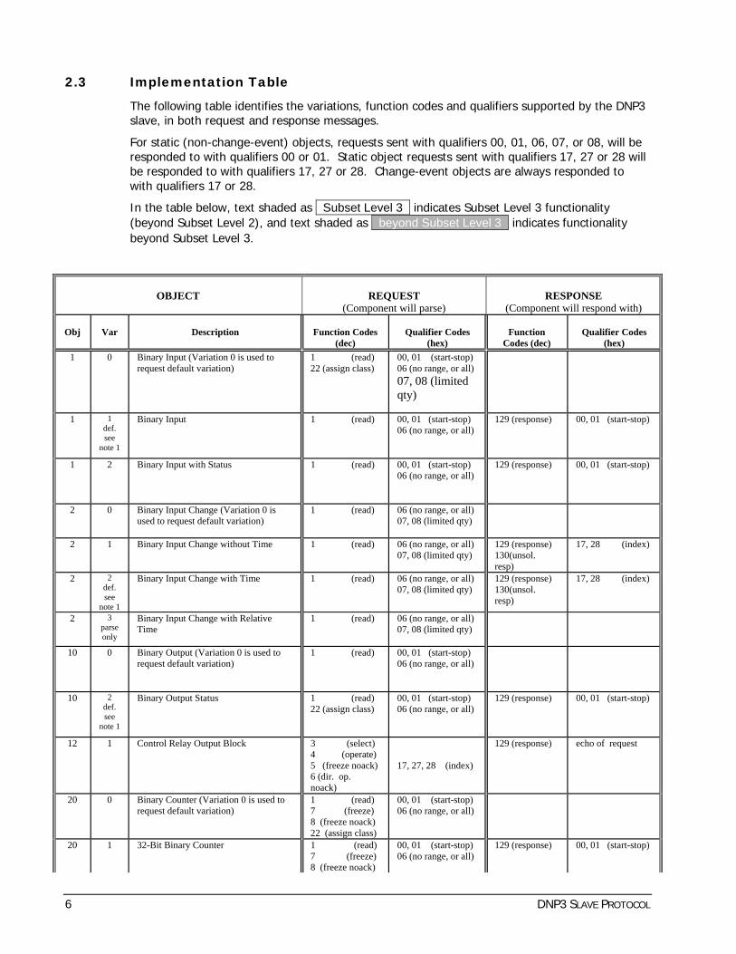
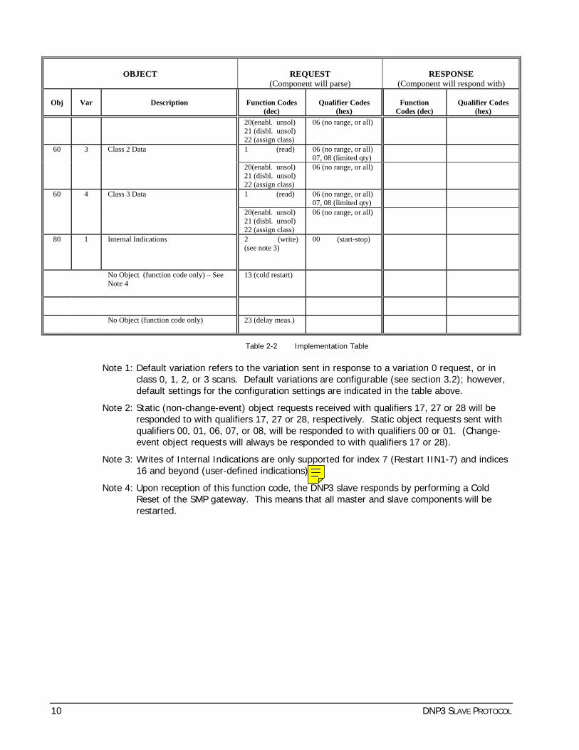
2.3 Implementation Table
The following table identifies the variations, function codes and qualifiers supported by the DNP3 slave, in both request and response messages.
For static (non-change-event) objects, requests sent with qualifiers 00, 01, 06, 07, or 08, will be responded to with qualifiers 00 or 01. Static object requests sent with qualifiers 17, 27 or 28 will be responded to with qualifiers 17, 27 or 28. Change-event objects are always responded to with qualifiers 17 or 28.
In the table below, text shaded as Subset Level 3 indicates Subset Level 3 functionality (beyond Subset Level 2), and text shaded as beyond Subset Level 3 indicates functionality beyond Subset Level 3.
OBJECT
REQUEST
(Component will parse)
RESPONSE
(Component will respond with) Obj
Var
Description
Function Codes
(dec)
Qualifier Codes
(hex)
Function
Codes (dec)
Qualifier Codes
(hex) 1 0 Binary Input (Variation 0 is used to
request default variation) 1 (read) 22 (assign class)
00, 01 (start-stop) 06 (no range, or all) 07, 08 (limited qty) 17, 28 (index)
1 1 def. see
note 1
Binary Input 1 (read) 22 (assign class)
00, 01 (start-stop) 06 (no range, or all) 07, 08 (limited qty) 17, 28 (index)
129 (response) 00, 01 (start-stop) 17, 28 (index- see note 2)
1 2 Binary Input with Status 1 (read) 22 (assign class)
00, 01 (start-stop) 06 (no range, or all) 07, 08 (limited qty) 17, 28 (index)
129 (response) 00, 01 (start-stop) 17, 28 (index- see note 2)
2 0 Binary Input Change (Variation 0 is used to request default variation)
1 (read) 06 (no range, or all) 07, 08 (limited qty)
2
1 Binary Input Change without Time 1 (read) 06 (no range, or all) 07, 08 (limited qty)
129 (response) 130(unsol. resp)
17, 28 (index)
2 2 def. see
note 1
Binary Input Change with Time
1 (read) 06 (no range, or all) 07, 08 (limited qty)
129 (response) 130(unsol. resp)
17, 28 (index)
2 3 parse only
Binary Input Change with Relative Time
1 (read) 06 (no range, or all) 07, 08 (limited qty)
10 0 Binary Output (Variation 0 is used to request default variation)
1 (read) 00, 01 (start-stop) 06 (no range, or all) 07, 08 (limited qty) 17, 28 (index)
10 2 def. see
note 1
Binary Output Status
1 (read) 22 (assign class)
00, 01 (start-stop) 06 (no range, or all) 07, 08 (limited qty) 17, 28 (index)
129 (response) 130(unsol. resp)
00, 01 (start-stop) 17, 28 (index- see note 2)
12
1 Control Relay Output Block 3 (select) 4 (operate) 5 (freeze noack) 6 (dir. op. noack)
00, 01 (start-stop) 07, 08 (limited qty) 17, 27, 28 (index)
129 (response) echo of request
20 0 Binary Counter (Variation 0 is used to request default variation)
1 (read) 7 (freeze) 8 (freeze noack) 22 (assign class)
00, 01 (start-stop) 06 (no range, or all) 07, 08 (limited qty) 17, 28 (index)
20 1 32-Bit Binary Counter 1 (read) 7 (freeze) 8 (freeze noack)
00, 01 (start-stop) 06 (no range, or all) 07, 08 (limited qty)
129 (response) 00, 01 (start-stop) 17, 28 (index- see note 2)
6 DNP3 SLAVE PROTOCOL

OBJECT
REQUEST
(Component will parse)
RESPONSE
(Component will respond with) Obj
Var
Description
Function Codes
(dec)
Qualifier Codes
(hex)
Function
Codes (dec)
Qualifier Codes
(hex) 22 (assign class) 17, 28 (index)
20 2 16-Bit Binary Counter 1 (read)
7 (freeze) 8 (freeze noack) 22 (assign class)
00, 01 (start-stop) 06 (no range, or all) 07, 08 (limited qty) 17, 28 (index)
129 (response) 00, 01 (start-stop) 17, 28 (index- see note 2)
20 5 32-Bit Binary Counter without Flag 1 (read) 7 (freeze) 8 (freeze noack) 22 (assign class)
00, 01 (start-stop) 06 (no range, or all) 07, 08 (limited qty) 17, 28 (index)
129 (response) 00, 01 (start-stop) 17, 28 (index- see note 2)
20 6 def. see
note 1
16-Bit Binary Counter without Flag 1 (read) 7 (freeze) 8 (freeze noack) 22 (assign class)
00, 01 (start-stop) 06 (no range, or all) 07, 08 (limited qty) 17, 28 (index)
129 (response) 00, 01 (start-stop) 17, 28 (index- see note 2)
21 0 Frozen Counter (Variation 0 is used to request default variation)
1 (read) 22 (assign class)
00, 01 (start-stop) 06 (no range, or all) 07, 08 (limited qty) 17, 28 (index)
21 1 32-Bit Frozen Counter 1 (read) 22 (assign class)
00, 01 (start-stop) 06 (no range, or all) 07, 08 (limited qty) 17, 28 (index)
129 (response) 00, 01 (start-stop) 17, 28 (index- see note 2)
21 2 16-Bit Frozen Counter 1 (read) 22 (assign class)
00, 01 (start-stop) 06 (no range, or all) 07, 08 (limited qty) 17, 28 (index)
129 (response) 00, 01 (start-stop) 17, 28 (index- see note 2)
21 9 32-Bit Frozen Counter without Flag 1 (read) 22 (assign class)
00, 01 (start-stop) 06 (no range, or all) 07, 08 (limited qty) 17, 28 (index)
129 (response) 00, 01 (start-stop) 17, 28 (index- see note 2)
21 10 def. see
note 1
16-Bit Frozen Counter without Flag 1 (read) 22 (assign class)
00, 01 (start-stop) 06 (no range, or all) 07, 08 (limited qty) 17, 28 (index)
129 (response) 00, 01 (start-stop) 17, 28 (index- see note 2)
22 0 Counter Change Event (Variation 0 is used to request default variation)
1 (read) 06 (no range, or all) 07, 08 (limited qty)
22 1 32-Bit Counter Change Event without Time
1 (read) 06 (no range, or all) 07, 08 (limited qty)
129 (response) 130(unsol. resp)
17, 28 (index)
22 2 def. see
note 1
16-Bit Counter Change Event without Time
1 (read)
06 (no range, or all) 07, 08 (limited qty)
129 (response) 130(unsol. resp)
17, 28 (index)
22 5 32-Bit Counter Change Event with Time
1 (read)
06 (no range, or all) 07, 08 (limited qty)
129 (response) 130(unsol. resp)
17, 28 (index)
22 6 16-Bit Counter Change Event with Time
1 (read)
06 (no range, or all) 07, 08 (limited qty)
129 (response) 130(unsol. resp)
17, 28 (index)
23 0 Frozen Counter Event (Variation 0 is used to request default variation)
1 (read)
06 (no range, or all) 07, 08 (limited qty)
23 1 32-Bit Frozen Counter Event without Time
1 (read)
06 (no range, or all) 07, 08 (limited qty)
129 (response) 130(unsol. resp)
17, 28 (index)
23 2 def. see
note 1
16-Bit Frozen Counter Event without Time
1 (read)
06 (no range, or all) 07, 08 (limited qty)
129 (response) 130(unsol. resp)
17, 28 (index)
23 5 32-Bit Frozen Counter Event with Time
1 (read)
06 (no range, or all) 07, 08 (limited qty)
129 (response) 130(unsol. resp)
17, 28 (index)
23 6 16-Bit Frozen Counter Event with Time 1 (read) 06 (no range, or all) 129 (response) 17, 28 (index)
DNP3 SLAVE PROTOCOL 7

OBJECT
REQUEST
(Component will parse)
RESPONSE
(Component will respond with) Obj
Var
Description
Function Codes
(dec)
Qualifier Codes
(hex)
Function
Codes (dec)
Qualifier Codes
(hex)
07, 08 (limited qty) 130(unsol. resp)
30 0 Analog Input (Variation 0 is used to request default variation)
1 (read) 22 (assign class)
00, 01 (start-stop) 06 (no range, or all) 07, 08 (limited qty) 17, 28 (index)
30 1 32-Bit Analog Input 1 (read) 22 (assign class)
00, 01 (start-stop) 06 (no range, or all) 07, 08 (limited qty) 17, 28 (index)
129 (response) 00, 01 (start-stop) 17, 28 (index- see note 2)
30 2 def. see
note 1
16-Bit Analog Input 1 (read) 22 (assign class)
00, 01 (start-stop) 06 (no range, or all) 07, 08 (limited qty) 17, 28 (index)
129 (response) 00, 01 (start-stop) 17, 28 (index- see note 2)
30 3 32-Bit Analog Input without Flag 1 (read) 22 (assign class)
00, 01 (start-stop) 06 (no range, or all) 07, 08 (limited qty) 17, 28 (index)
129 (response) 00, 01 (start-stop) 17, 28 (index- see note 2)
30 4 16-Bit Analog Input without Flag 1 (read) 22 (assign class)
00, 01 (start-stop) 06 (no range, or all) 07, 08 (limited qty) 17, 28 (index)
129 (response) 00, 01 (start-stop) 17, 28 (index- see note 2)
30 5 Short floating point 1 (read) 22 (assign class)
00, 01 (start-stop) 06 (no range, or all) 07, 08 (limited qty) 17, 28 (index)
129 (response) 00, 01 (start-stop) 17, 28 (index- see note 2)
32 0 Analog Change Event (Variation 0 is used to request default variation)
1 (read) 06 (no range, or all) 07, 08 (limited qty)
32 1 32-Bit Analog Change Event without Time
1 (read)
06 (no range, or all) 07, 08 (limited qty)
129 (response) 130(unsol. resp)
17, 28 (index)
32 2 def. see
note 1
16-Bit Analog Change Event without Time
1 (read) 06 (no range, or all) 07, 08 (limited qty)
129 (response) 130(unsol. resp)
17, 28 (index)
32 3 32-Bit Analog Change Event with Time 1 (read) 06 (no range, or all) 07, 08 (limited qty)
129 (response) 130(unsol. resp)
17, 28 (index)
32 4 16-Bit Analog Change Event with Time 1 (read) 06 (no range, or all) 07, 08 (limited qty)
129 (response) 130(unsol. resp)
17, 28 (index)
32 5 Short floating point Analog Change Event without Time
1 (read) 06 (no range, or all) 07, 08 (limited qty)
129 (response) 130(unsol. resp)
17, 28 (index)
32 7 Short floating point Analog Change Event with Time
1 (read) 06 (no range, or all) 07, 08 (limited qty)
129 (response) 130(unsol. resp)
17, 28 (index)
34 0 Analog Input Reporting Deadband (Variation 0 is used to request default variation)
1 (read) 00, 01 (start-stop) 06 (no range, or all) 07, 08 (limited qty) 17, 28 (index)
1 (read) 00, 01 (start-stop) 06 (no range, or all) 07, 08 (limited qty) 17, 28 (index)
129 (response) 00, 01 (start-stop) 17, 28 (index- see note 2)
34 1 def. see
note 1
16-Bit Analog Input Reporting Deadband
2 (write) 00, 01 (start-stop) 07, 08 (limited qty) 17, 28 (index)
34 2 32-Bit Analog Input Reporting Deadband
1 (read) 00, 01 (start-stop) 06 (no range, or all) 07, 08 (limited qty) 17, 28 (index)
129 (response) 00, 01 (start-stop) 17, 28 (index- see note 2)
8 DNP3 SLAVE PROTOCOL

OBJECT
REQUEST
(Component will parse)
RESPONSE
(Component will respond with) Obj
Var
Description
Function Codes
(dec)
Qualifier Codes
(hex)
Function
Codes (dec)
Qualifier Codes
(hex) 2 (write) 00, 01 (start-stop)
07, 08 (limited qty) 17, 28 (index)
1 (read) 00, 01 (start-stop) 06 (no range, or all) 07, 08 (limited qty) 17, 28 (index)
129 (response) 00, 01 (start-stop) 17, 28 (index- see note 2)
34 3 Short floating point Analog Input Reporting Deadband
2 (write) 00, 01 (start-stop) 07, 08 (limited qty) 17, 28 (index)
40 0 Analog Output Status (Variation 0 is used to request default variation)
1 (read) 00, 01 (start-stop) 06 (no range, or all) 07, 08 (limited qty) 17, 28 (index)
40 1 32-Bit Analog Output Status 1 (read) 22 (assign class)
00, 01 (start-stop) 06 (no range, or all) 07, 08 (limited qty) 17, 28 (index)
129 (response) 130(unsol. resp)
00, 01 (start-stop) 17, 28 (index- see note 2)
40 2 def. see
note 1
16-Bit Analog Output Status 1 (read) 22 (assign class)
00, 01 (start-stop) 06 (no range, or all) 07, 08 (limited qty) 17, 28 (index)
129 (response) 130(unsol. resp)
00, 01 (start-stop) 17, 28 (index- see note 2)
40 3 Short floating point Analog Output Status
1 (read) 22 (assign class)
00, 01 (start-stop) 06 (no range, or all) 07, 08 (limited qty) 17, 28 (index)
129 (response) 130(unsol. resp)
00, 01 (start-stop) 17, 28 (index- see note 2)
41 1 32-Bit Analog Output Block 3 (select) 4 (operate) 5 (direct operate) 6(dir. op. noack)
00, 01 (start-stop) 07, 08 (limited qty) 17, 27, 28 (index)
129 (response) echo of request
41 2 16-Bit Analog Output Block 3 (select) 4 (operate) 5 (direct operate) 6 (dir. op. noack)
00, 01 (start-stop) 07, 08 (limited qty) 17, 27, 28 (index)
129 (response) echo of request
41 3 Short floating point Analog Output Block
3 (select) 4 (operate) 5 (direct operate) 6 (dir. op. noack)
00, 01 (start-stop) 07, 08 (limited qty) 17, 28 (index)
129 (response) echo of request
50 0 Time and Date (Variation 0 is used to request default variation)
1 (read)
00, 01 (start-stop) 06 (no range, or all) 07, 08 (limited qty) 17, 28 (index)
129 (response) 00, 01 (start-stop) 17, 28 (index- see note 2)
1 (read)
00, 01 (start-stop) 06 (no range, or all) 07 (limited qty=1) 08 (limited qty) 17, 28 (index)
129 (response)
00, 01 (start-stop) 17, 28 (index- see note 2)
50 1 Time and Date
2 (write) 00, 01 (start-stop) 07 (limited qty = 1) 08 (limited qty) 17, 28 (index)
52 2 Time Delay Fine
129 (response) 07 (limited qty = 1)
60 0 Class 0, 1, 2 and 3 Data 1 (read) 20 (enabl. unsol) 21 (disbl. unsol)
06 (no range, or all)
60 1 Class 0 Data 1 (read) 22 (assign class)
06 (no range, or all)
60 2 Class 1 Data 1 (read) 06 (no range, or all) 07, 08 (limited qty)
DNP3 SLAVE PROTOCOL 9
OBJECT
REQUEST
(Component will parse)
RESPONSE
(Component will respond with) Obj
Var
Description
Function Codes
(dec)
Qualifier Codes
(hex)
Function
Codes (dec)
Qualifier Codes
(hex) 20(enabl. unsol) 21 (disbl. unsol) 22 (assign class)
06 (no range, or all)
1 (read) 06 (no range, or all) 07, 08 (limited qty)
60 3 Class 2 Data
20(enabl. unsol) 21 (disbl. unsol) 22 (assign class)
06 (no range, or all)
1 (read) 06 (no range, or all) 07, 08 (limited qty)
60 4 Class 3 Data
20(enabl. unsol) 21 (disbl. unsol) 22 (assign class)
06 (no range, or all)
80 1 Internal Indications 2 (write) (see note 3)
00 (start-stop) 01 (start-stop) 07, 08 (limited qty) 17, 28 (index)
No Object (function code only) – See Note 4
13 (cold restart)
No Object (function code only)
14(warm restart)
No Object (function code only) 23 (delay meas.)
Table 2-2 Implementation Table
Note 1: Default variation refers to the variation sent in response to a variation 0 request, or in class 0, 1, 2, or 3 scans. Default variations are configurable (see section 3.2); however, default settings for the configuration settings are indicated in the table above.
Note 2: Static (non-change-event) object requests received with qualifiers 17, 27 or 28 will be responded to with qualifiers 17, 27 or 28, respectively. Static object requests sent with qualifiers 00, 01, 06, 07, or 08, will be responded to with qualifiers 00 or 01. (Change-event object requests will always be responded to with qualifiers 17 or 28).
Note 3: Writes of Internal Indications are only supported for index 7 (Restart IIN1-7) and indices 16 and beyond (user-defined indications).
Note 4: Upon reception of this function code, the DNP3 slave responds by performing a Cold Reset of the SMP gateway. This means that all master and slave components will be restarted.
10 DNP3 SLAVE PROTOCOL

3. Configuration Settings This chapter enumerates the configuration settings to be specified for each DNP3 slave protocol instance. Cybectec’s SMP Config software is generally used to define these settings.
Note that the DNP3 slave component also generates binary inputs that require no configuration.
3.1 General Settings
Each instance of this slave protocol component contains general settings, which set the general behavior of the component. The following table shows the general settings for the DNP3 slave protocol.
Setting Description
Device Prefix The name that identifies the component instance.
When a device prefix is specified, certain logical binary points are generated by the DNP3 slave component (see 5.8.7 Generated Binary Inputs).
Link Address The DNP data link address of this logical DNP3 slave device.
This address must be unique for each instance that uses a particular multidrop link.
Range: 0 to 65,519 (65,520 to 66,535 are reserved for broadcast addresses)
Default value: 1
Master Link Address The DNP data link address of the remote device with which this device communicates.
Range: 0 to 65,519 (65,520 to 66,535 are reserved for broadcast addresses)
Default value: 1
Inactivity Timeout The number of seconds that the component will wait after the last valid data link layer frame is received, before resetting the communications link.
If set to 0, the inactivity timeout is disabled.
Range: 0 to 1,000,000 secs
Default value: 300
Unavailability Timeout
The number of seconds that the slave component will wait after the last valid data link layer frame is received or the last connection request from the master, before declaring the link unavailable.
If set to 0, the unavailability timeout is disabled.
The link availability state is published using the “___LinkAvailaible” logical point (see 5.8.7).
Range: 0 to 1,000,000 secs
Default value: 60 secs
DNP3 SLAVE PROTOCOL 11

Setting Description
Control Enabled A checkmark enables control operations by the master on output points.
Range: checkmark / no checkmark
Default value: checkmark
Selection Timeout The number of milliseconds following a select command, during which an operate command must be received before the selection times out.
A 0 value will cause an immediate timeout.
Range: 0 to 2,147,483,647 ms
Default value: 10,000 ms
Need Time Delay The number of milliseconds to which the "need time" Internal Indication (IIN) (contained in every application response message) must be set for the master station to write time back to the device.
Set this value to 0 if the component does not support exception reporting or if there is no reason for synchronizing the slave component time with the master component time (no time-stamped data reported).
Range: 0 to 2,147,483,647 ms
Default value: 1,800,000 ms (30 mins)
Unsolicited Report A checkmark enables unsolicited responses; the latter are configured and must be specifically enabled by the master after an initial empty unsolicited response.
If there is no checkmark, unsolicited responses are not configured and can never be enabled by the master.
Range: checkmark / no checkmark
Default value: checkmark
Unsolicited Max Retries
The number of attempts to re-transmit an unsolicited response without getting a confirmation from the master station.
Note: A value of 255 allows for unlimited retries.
Range: 0 to 255
Default value: 2
Unsolicited Retry Delay
If an unsolicited response is not confirmed within the application confirmation timeout, this setting controls how soon another unsolicited response will be sent.
If this setting is 0 or less than the application confirmation timeout, the "retry" unsolicited response will be sent as soon as the application confirmation timeout expires (unless a read request was received in the meantime, in which case the read request will be responded to first).
Range: 0 to 2,147,483,647 ms
Default value: 0
12 DNP3 SLAVE PROTOCOL

Setting Description
Class 1 Report Min Event
For class 1 events, this setting controls the conditions under which an unsolicited response will be sent. If the number of events in this class matches or exceeds this value, an unsolicited response will be sent.
When in switched mode, these conditions lead to the initiation of an outgoing connection, if allowed. See section 5.3 - Switched Mode.
Range: 1 to 65,535
Default value: 10
Class 2 Report Min Event
For class 2 events, this setting controls the condition under which an unsolicited response will be sent. If the number of events in this class matches or exceeds this value, an unsolicited response will be sent.
When in switched mode, these conditions lead to the initiation of an outgoing connection, if allowed. See section 5.3 - Switched Mode.
Range: 1 to 65,535
Default value: 10
Class 3 Report Min Event
For class 3 events, this setting controls the condition under which an unsolicited response will be sent. If the number of events in this class matches or exceeds this value, an unsolicited response will be sent.
When in switched mode, these conditions lead to the initiation of an outgoing connection, if allowed. See section 5.3 - Switched Mode.
Range: 1 to 65,535
Default value: 10
Class 1 Report Delay
For class 1 change events, this setting can be used to control the conditions under which an unsolicited response is sent. If the time after an event occurs matches or exceeds this value, even if only one event has occurred, an unsolicited response will be sent.
Note: If this value is set to 0, it will not be used, and only the Class 1 Report Min Event values will determine when an unsolicited response is sent.
When in switched mode, these conditions lead to the initiation of an outgoing connection, if allowed. See section 5.3 - Switched Mode.
Range: 0 to 2,147,483,647 ms
Default value: 15,000 ms
Class 2 Report Delay
For class 2 change events, this setting can be used to control the conditions under which an unsolicited response is sent. If the time after an event occurs matches or exceeds this value, even if only one event has occurred, an unsolicited response will be sent.
Note: If this value is set to 0, it will not be used, and only the Class 2 Report Min Event values will determine when an unsolicited response is sent.
When in switched mode, these conditions lead to the initiation of an
DNP3 SLAVE PROTOCOL 13

Setting Description outgoing connection, if allowed. See section 5.3 - Switched Mode.
Range: 0 to 2,147,483,647 ms
Default value: 15,000 ms
Class 3 Report Delay
For class 3 change events, this setting can be used to control the conditions under which an unsolicited response is sent. If the time after an event occurs matches or exceeds this value, even if only one event has occurred, an unsolicited response will be sent.
Note: If this value is set to 0, it will not be used, and only the Class 3 Report Min Event values will determine when an unsolicited response is sent.
When in switched mode, these conditions lead to the initiation of an outgoing connection, if allowed. See section 5.3 - Switched Mode.
Range: 0 to 2,147,483,647 ms
Default value: 15,000 ms
Link Confirmation Indicates the link layer confirmation mode that the component will request from the master station.
Note: Data link confirm should be disabled when communicating with TCP/IP.
Allowed values: Never Not for any frame Sometimes For multi-frame fragments only Always For all frames
Default value: Never
Link Confirmation Timeout
The number of milliseconds to wait for the remote device data link layer confirmation of the last frame sent before attempting any retries (only if the frame is sent with confirm requested). Measured after the last byte of the data frame is sent.
A value of 0 causes an immediate timeout.
Range: 0 to 2,147,483,647 ms
Default value: 1,500 ms
Link Max Retries The number of attempts made to re-transmit a data link frame that was not confirmed by the master station (only if the frame is sent with confirm requested).
Range: 0 to 255
Default value: 2
Applic Confirmation Timeout
The number of milliseconds to wait for the master station to confirm the previous response, if requested.
Note: If application layer confirmations are used with data link confirmations, make sure the application layer confirmation timeout is long enough for all data link retries to complete. The following formula describes this requirement:
Applic Confirmation Timeout > Link Confirmation Timeout * (Link Max Re ries + 1) t
14 DNP3 SLAVE PROTOCOL

Setting Description
Range: 0 to 2,147,483,647 ms
Default value: 5,000 ms
Events Keep Time The number of seconds that buffered change events are kept after a link reset. After this number of seconds, the buffers are flushed and new events aren't buffered until a new "active" connection is established. An "active" connection begins when a valid data link layer frame is received.
If this value is set to 0, the mechanism is disabled, i.e., buffered change events are always kept and new events are always buffered. This is also true at system startup.
Range: 0 to 2,073,600 secs (24 days)
Default value: 300 secs (5 mins)
Max Connection Delay
The maximum number of seconds to wait for a master component initial general interrogation scan completed notification.
This allows slave components to wait before allowing connections from a master, until master components (those configured to do so) either complete their first general interrogation scan, or time out if the communication cannot be established. Thus, after an SMP restart, the master does not see any useless transitions resulting from system initialization.
Range: 0 to 86,400 secs
Default value: 0 secs
Int. Ch. Delay The maximum number of milliseconds between the reception of 2 characters.
Range: 0 to 60,000 ms
Default value: 50 ms
Hot-Standby Support
Indicates the startup status of the slave on the standby SMP.
Allowed values: Disabled Slave not started.
Acquisition Slave started, no control allowed.
Acquisition and Control Slave started, control allowed.
Default value: Disabled
Table 3-3 General Settings
DNP3 SLAVE PROTOCOL 15

3.2 Default Variation Settings
Default variations are used when the master station requests variation 0 (default variation) for a given object. There must be a single group of settings per slave protocol instance.
Setting Description
01 Binary Input Default variation for object 01 – Binary Input
Allowed values: Single-Bit Binary Input Binary Input With Status
Default value: Binary Input With Status
02 Binary Input Change
Default variation for object 02 – Binary Input Change Event
Allowed values: BI Change Without Time BI Change With Time
Default value: BI Change With Time
20 Binary Counter Default variation for object 20 – Binary Counter
Allowed values: 32-Bit Binary Counter 16-Bit Binary Counter 32-Bit Counter Without Flag 16-Bit Counter Without Flag
Default value: 16-Bit Counter
21 Frozen Counter Default variation for object 21 – Frozen Counter
Allowed values: 32-Bit Frozen Counter 16-Bit Frozen Counter 32-Bit Frozen Cnt Without Flag 16-Bit Frozen Cnt Without Flag
Default value: 16-Bit Frozen Counter
22 Binary Counter Change
Default variation for object 22 – Binary Counter Change Event
Allowed values: 32-Bit Change Event Without Time 16-Bit Change Event Without Time 32-Bit Cnt Chg Event With Time 16-Bit Cnt Chg Event With Time
Default value: 16-Bit Change Event Without Time
23 Frozen Counter Change
Default variation for object 23 – Frozen Counter Change Event
Allowed values: 32-Bit Frozen Counter Event 16-Bit Frozen Counter Event 32-Bit Frozen Counter Event With Time 16-Bit Frozen Counter Event With Time
Default value: 16-Bit Frozen Counter Event
30 Analog Input Default variation for object 30 – Analog Input
Allowed values: 32-Bit Analog Input 16-Bit Analog Input 32-Bit Analog Input Without Flag 16-Bit Analog Input Without Flag Short Float Analog Input
16 DNP3 SLAVE PROTOCOL

Setting Description
Default value: 16-Bit Analog Input
32 Analog Input Change
Default variation for object 32 – Analog Input Change Event
Allowed values: 32-Bit Analog Change Event 16-Bit Analog Change Event 32-Bit Anal Chg Event With Time 16-Bit Anal Chg Event With Time Short Float Analog Change Event Without Time Short Float Analog Change Event With Time
Default value: 16-Bit Analog Change Event
34 Analog Input Reporting Deadband
Default variation for object 34 – Analog Input Reporting Deadband
Allowed values: 16-Bit Analog Input Reporting Deadband 32-Bit Analog Input Reporting Deadband Short Float Analog Input Reporting Deadband
Default value: 16-Bit Analog Input Reporting Deadband
40 Analog Output Default variation for object 40 – Analog Output
Allowed values: 32-Bit Analog Output Status 16-Bit Analog Output Status Short Float Analog Output Status
Default value: 16-Bit Analog Output Status
Table 3-4 Default Variation Settings
3.3 Switched Connection Settings
Switched connection settings define protocol behavior when the communications link is not used on a permanent basis. These settings are therefore not required when using a permanent connection. A single set of these settings is allowed per protocol instance.
Setting Description
Enabled A checkmark indicates that switched connection mode is enabled.
Range: checkmark / no checkmark
Default value: no checkmark
Allow Outgoing Connections
A checkmark indicates that the DNP3 slave can initiate outgoing connections. If you put a checkmark, the DNP3 slave must be configured with two connections: a server connection for incoming connections and a client connection for outgoing connections.
Allowed values: checkmark / no checkmark
Default values: no checkmark
Max Retries Defines the maximum number of connection retries before the communication with the master station is considered as having failed.
Range: 0 to 14
DNP3 SLAVE PROTOCOL 17

Setting Description
Default values: 3
Retry Delay Defines the time interval between connection retries (Max Retries).
Range: 0 to 2,147,483,647 ms
Default values: 300,000 ms
Table 3-5 Switched Connection Settings
3.4 Switched Connection Schedule Settings
Switched connection schedule settings define, on a 24-hour basis, the configuration of scheduled outgoing connections when a switched connection is used. These settings are not required when a permanent connection is used, and are optional when a switched connection is used. An outgoing connection is, however, required for the schedule to take effect. A single group of these settings is allowed per protocol instance.
Setting Description
Start Time Time of day, starting at midnight, at which communication with the master station is allowed.
Range: 0 to 1439 mins
Stop Time Time of day, starting at midnight, at which communication with the master station is no longer allowed.
Range: 0 to 1439 mins
Comm Cycle Time between two calls to the master station.
Note: When Start Time equals Stop Time, then there is "round the clock" usage. For example, to configure two calls a day, one at 7 AM and the other at 7 PM, set:
Start Time = Stop Time = 7h x 60min = 420 and
Comm Cycle = 12h x 60min = 720.
Range: 1 to 1440 mins
Table 3-6 Switched Connection Schedule Settings
3.5 Analog Input Settings
Each instance of the slave protocol component may contain several analog input points to be reported to the master station. Analog input settings tell the component how to map analog inputs from the RTDX to protocol addresses. The following table shows the analog input settings for the DNP3 slave protocol.
Setting Description
Index Index of the point.
Name The name that identifies the point. This name must be unique for each analog input point.
18 DNP3 SLAVE PROTOCOL
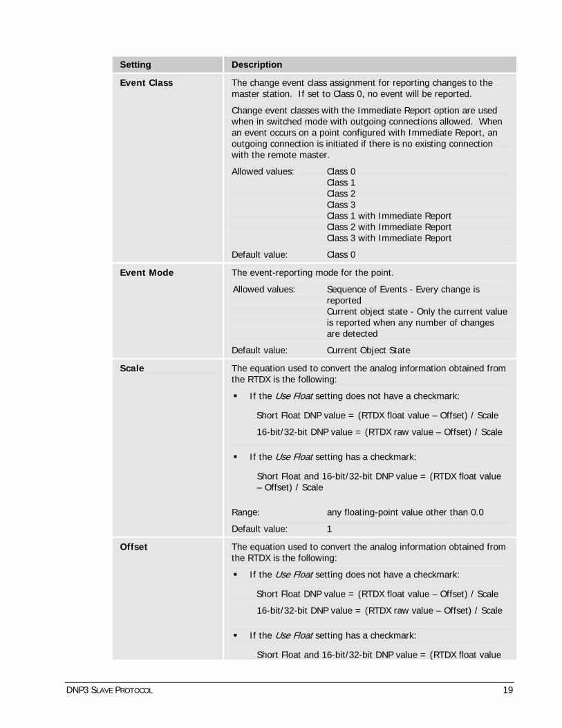
Setting Description
Event Class The change event class assignment for reporting changes to the master station. If set to Class 0, no event will be reported.
Change event classes with the Immediate Report option are used when in switched mode with outgoing connections allowed. When an event occurs on a point configured with Immediate Report, an outgoing connection is initiated if there is no existing connection with the remote master.
Allowed values: Class 0 Class 1 Class 2 Class 3 Class 1 with Immediate Report Class 2 with Immediate Report Class 3 with Immediate Report
Default value: Class 0
Event Mode The event-reporting mode for the point.
Allowed values: Sequence of Events - Every change is reported Current object state - Only the current value is reported when any number of changes are detected
Default value: Current Object State
Scale The equation used to convert the analog information obtained from the RTDX is the following:
If the Use Float setting does not have a checkmark:
Short Float DNP value = (RTDX float value – Offset) / Scale
16-bit/32-bit DNP value = (RTDX raw value – Offset) / Scale
If the Use Float setting has a checkmark:
Short Float and 16-bit/32-bit DNP value = (RTDX float value – Offset) / Scale
Range: any floating-point value other than 0.0
Default value: 1
Offset The equation used to convert the analog information obtained from the RTDX is the following:
If the Use Float setting does not have a checkmark:
Short Float DNP value = (RTDX float value – Offset) / Scale
16-bit/32-bit DNP value = (RTDX raw value – Offset) / Scale
If the Use Float setting has a checkmark:
Short Float and 16-bit/32-bit DNP value = (RTDX float value
DNP3 SLAVE PROTOCOL 19

Setting Description – Offset) / Scale
Range: any floating-point value
Default value: 0
Use Float Put a checkmark to specify that when both RAW and FLOAT RTDX values are available, the FLOAT value is to be used.
Range: checkmark / no checkmark
Default value: no checkmark
Deadband Floating-point deadband value. Only changes larger than the deadband will be reported to the master station. A value of 0.0 implies that all transitions, no matter how small, will be reported.
Range: 0.0 to 3.4E38
Default value: 0.0
Report Deadband Floating-point deadband value dedicated to communication management. In switched mode, the DNP3 slave initiates a connection only when there are changes larger than the specified deadband.
Report deadbands are used only between communication sessions. When a communication is established, the Deadband setting is used, as usual.
NOTE: This setting is relevant only with switched connections.
Range: 0.0 to 3.4E38
Default value: 0.0
Table 3-7 Analog Input Settings
3.6 Binary Input Settings
Each instance of the slave protocol component may contain several binary input points to be reported to the master station. Binary input settings tell the component how to map binary inputs from the RTDX to protocol addresses. The following table shows the binary input settings for the DNP3 slave protocol.
Setting Description
Index Index of the point.
Name The name that identifies the point. This name must be unique for each binary input point.
Event Class The change event class assignment for reporting changes to the master station. If set to Class 0, no event will be reported.
Change event classes with the Immediate Report option are used when in switched mode with outgoing connections allowed. When an event occurs on a point configured with Immediate Report, an outgoing connection is initiated if there is no existing connection with the remote master.
20 DNP3 SLAVE PROTOCOL

Setting Description
Allowed values: Class 0 Class 1 Class 2 Class 3 Class 1 with Immediate Report Class 2 with Immediate Report Class 3 with Immediate Report
Default value: Class 1
Table 3-8 Binary Input Settings
3.7 Counter Input Settings
Each instance of the slave protocol component may contain several counter input points to be reported to the master station. Counter input settings tell the component how to map counter inputs from the RTDX to protocol addresses.
The DNP3 slave automatically creates a frozen counter point associated with each configured counter input point. On reception of a freeze command for a given counter input point, the current value of the point is stored in the associated frozen counter point, and may be reported to the master station.
The following table shows the counter input settings for the DNP3 slave protocol.
Setting Description
Index Index of the point.
Name The name that identifies the point. This name must be unique for each counter input point.
Event Class The change event class assignment for reporting changes to the master station. If set to Class 0, no event will be reported.
Change event classes with the Immediate Report option are used when in switched mode with outgoing connections allowed. When an event occurs on a point configured with Immediate Report, an outgoing connection is initiated if there is no existing connection with the remote master.
Allowed values: Class 0 Class 1 Class 2 Class 3 Class 1 with Immediate Report Class 2 with Immediate Report Class 3 with Immediate Report
Default value: Class 0
Event Mode The event-reporting mode for the point.
Allowed values: Sequence of Events - Every change is reported Current Object State - Only the current value is reported when any number of changes are detected
DNP3 SLAVE PROTOCOL 21

Setting Description
Default value: Current Object State
Deadband Deadband value. Only changes larger than the deadband will be reported to the master station. A value of 0 implies that all transitions, no matter how small, will be reported.
Range: 0 to 2,147,483,647
Default value: 0
Report Deadband Floating-point deadband value dedicated to communication management. In switched mode, the DNP3 slave initiates a connection only when there are changes larger than the specified deadband.
Report deadbands are used only between communication sessions. When a communication is established, the Deadband setting is used, as usual.
NOTE: This setting is relevant only with switched connections.
Range: 0 to 2,147,483,647
Default value: 0
Frozen Event Class The change event class assignment of the associated frozen counter point, for reporting changes to the master station. If set to Class 0, no event will be reported.
Change event classes with the Immediate Report option are used when in switched mode with outgoing connections allowed. When an event occurs on a point configured with Immediate Report, an outgoing connection is initiated if there is no existing connection with the remote master.
Allowed values: Class 0 Class 1 Class 2 Class 3 Class 1 with Immediate Report Class 2 with Immediate Report Class 3 with Immediate Report
Default value: Class 0
Frozen Event Mode The event-reporting mode for the associated frozen counter point.
Allowed values: Sequence of Events - Every change is reported Current object state - Only the current value is reported when any number of changes are detected
Default value: Current Object State
Frozen Deadband Deadband value for the associated frozen counter point. Only changes larger than the deadband will be reported to the master station. A value of 0 implies that all transitions, no matter how small, will be reported.
Range: 0 to 2,147,483,647
22 DNP3 SLAVE PROTOCOL

Setting Description
Default value: 0
Frozen Report Deadband
Floating-point deadband value dedicated to communication management. In switched mode, the DNP3 slave initiates a connection only when there are changes larger than the specified deadband.
Report deadbands are used only between communication sessions. When a communication is established, the Deadband setting is used, as usual.
NOTE: This setting is relevant only with switched connections.
Range: 0 to 2,147,483,647
Default value: 0
Table 3-9 Counter Input Settings
3.8 Analog Output Settings
Each instance of the slave protocol component may contain several analog output points to be reported to or controlled by a master station. Analog output settings tell the component how to map analog outputs from the RTDX to protocol addresses. The following table shows the analog output settings for the DNP3 slave protocol.
Setting Description
Index Index of the point.
Name The name that identifies the point. This name must be unique for each analog output point.
Event Class The change event class assignment for reporting changes to the master station. If set to Class 0, no event will be reported.
Change event classes with the Immediate Report option are used when in switched mode with outgoing connections allowed. When an event occurs on a point configured with Immediate Report, an outgoing connection is initiated if there is no existing connection with the remote master.
WARNING: Since the DNP protocol specification doesn’t define a change event object for analog output information, the object used for event reporting is object 40 – Analog Output Status. The variation used is taken from the 40 Analog Output setting of the Default Variations setting structure (see 3.2).
Allowed values: Class 0 Class 1 Class 2 Class 3 Class 1 with Immediate Report Class 2 with Immediate Report Class 3 with Immediate Report
Default value: Class 0
Event Mode The event-reporting mode for the point.
DNP3 SLAVE PROTOCOL 23

Setting Description
Allowed values: Sequence of Events - Every change is reported Current Object State - Only the current value is reported when any number of changes are detected
Default value: Current Object State
Scale The equation used to convert the analog information obtained from the RTDX is the following:
If the Use Float setting does not have a checkmark:
Short Float DNP value = (RTDX float value – Offset) / Scale
16-bit/32-bit DNP value = (RTDX raw value – Offset) / Scale
If the Use Float setting has a checkmark:
Short Float and 16-bit/32-bit DNP value = (RTDX float value – Offset) / Scale
Range: any floating-point value other than 0.0
Default value: 1
Offset The equation used to convert the analog information obtained from the RTDX is the following:
If the Use Float setting does not have a checkmark:
Short Float DNP value = (RTDX float value – Offset) / Scale
16-bit/32-bit DNP value = (RTDX raw value – Offset) / Scale
If the Use Float setting has a checkmark:
Short Float and 16-bit/32-bit DNP value = (RTDX float value – Offset) / Scale
Range: any floating-point value
Default value: 0
Use Float Put a checkmark to specify that when both RAW and FLOAT RTDX values are available, the FLOAT value is to be used.
Range: checkmark / no checkmark
Default value: no checkmark
Deadband Floating-point deadband value. Only changes larger than the deadband will be reported to the master station. A value of 0.0 implies that all transitions, no matter how small, will be reported.
Range: 0.0 to 3.4E38
Default value: 0.0
Report Deadband Floating-point deadband value dedicated to communication
24 DNP3 SLAVE PROTOCOL

Setting Description management. In switched mode, the DNP3 slave initiates a connection only when there are changes larger than the specified deadband.
Report deadbands are used only between communication sessions. When a communication is established, the Deadband setting is used, as usual.
NOTE: This setting is relevant only with switched connections.
Range: 0.0 to 3.4E38
Default value: 0.0
Simulated Control Confirmation
Indicates for which command type sent to the master protocol component that owns the point, simulated confirmations are required.
Simulated confirmation differs from real confirmation in that it is sent by the master protocol component before the operation is performed and confirmed by the remote device. A real confirmation is sent back only after the specified operation is performed and confirmed by the remote device.
WARNING: DIRECT EXECUTE commands will be processed the same way as EXECUTE commands.
Allowed values: Never SELECT only EXECUTE only SELECT and EXECUTE
Default value: SELECT and EXECUTE
Table 3-10 Analog Output Settings
3.9 Binary Output Settings
Each instance of the slave protocol component may contain several binary output points to be reported to or controlled by a master station. Binary output settings tell the component how to map binary outputs from the RTDX to protocol addresses. The following table shows the binary output settings for the DNP3 slave protocol.
Setting Description
Index Index of the point.
Name The name that identifies the point. This name must be unique for each binary output point.
Event Class The change event class assignment for reporting changes to the master station. If set to Class 0, no event will be reported.
Change event classes with the Immediate Report option are used when in switched mode with outgoing connections allowed. When an event occurs on a point configured with Immediate Report, an outgoing connection is initiated if there is no existing connection with the remote master.
WARNING: Since the DNP protocol specification doesn’t define a
DNP3 SLAVE PROTOCOL 25

Setting Description change event object for binary output information, the object used for event reporting is object 10 variation 02 – Binary Output Status.
Allowed values: Class 0 Class 1 Class 2 Class 3 Class 1 with Immediate Report Class 2 with Immediate Report Class 3 with Immediate Report
Default value: Class 0
Points Pairing Indicates how OPEN/CLOSE operations using two PULSE points are supported for this point, when such operations are supported. If they are supported, the next index is reserved and is used to define the second point of the pair, which will handle the complementary operation.
For example, if the point at index 8 is configured as a “Dual Point, Open First”, the point at index 9 is the complementary point of the pair. From the master station point of view, points 8 and 9 can be operated with a TRIP/CLOSE or LATCH ON/OFF control function. Thus, a TRIP or LATCH OFF operation on point 8 or 9 results in a PULSE command on point 8, and a CLOSE or LATCH ON operation on point 8 or 9 results in a PULSE command on point 9.
Allowed values: None Dual Point Open/Close, Open First Dual Point Open/Close, Close First
Default value: None
Simulated Control Confirmation
Indicates for which command type sent to the master protocol component that owns the point, simulated confirmations are required.
A simulated confirmation differs from a real confirmation in that it is sent by the master protocol component before the operation is performed and confirmed by the remote device. A real confirmation is sent back only after the specified operation is performed and confirmed by the remote device.
WARNING: DIRECT EXECUTE commands will be processed the same way as EXECUTE commands.
Allowed values: Never SELECT only EXECUTE only SELECT and EXECUTE
Default value: SELECT and EXECUTE
Table 3-11 Binary Output Settings
26 DNP3 SLAVE PROTOCOL
3.10 Comma-Separated Values File Format
Using SMP Config, you can import or export a CSV (Comma-Separated Values) file containing your SMP gateway configuration.
Refer to the document entitled SMP Config CSV Format Definition, where you will find a description of the format to be used in defining the various DNP3 slave protocol settings.
DNP3 SLAVE PROTOCOL 27

4. Multiple Instances There is no practical limit to the number of DNP3 slave instances that can be simultaneously loaded on the SMP. Multiple instances may be connected to individual serial links, grouped together on multi-drop links in any combination, or connected to individual network connections over TCP/IP. However, each DNP3 slave requires a separate instance of configuration settings.
28 DNP3 SLAVE PROTOCOL
5. Operations The DNP3 slave component interacts with a DNP3 master station device by receiving requests and sending responses to these requests. It may also send unsolicited responses, if configured to do so. Operations performed through the DNP task cycle are described in this chapter.
5.1 Startup Sequence
The DNP3 slave component is loaded by the main SMP gateway application. The startup sequence of the component begins when the SMP gateway application initializes the component, giving it a handle to the configured communications link specified in the configuration file.
The step-by-step procedure required to initialize the DNP3 slave is described below:
Register with the Time Component* services.
Register with the Trace Component* services.
Register with the Statistics Component* services.
Register with the Log Component* services.
Validate the configuration block received from the main application.
Create the real-time database, which subscribes to all I/O points specified in the configuration file, via the RTDX Component*.
Initialize the communications link.
* All these components are part of the SMP gateway application.
All the above steps must be carried out successfully for the operation cycle to begin. Once initialized, the component waits for the main application to give the start command.
5.2 DNP Task Management
Interactions between the DNP3 slave component and the DNP3 master station are handled by the DNP task. The operation cycle begins when the SMP gateway application sends the START command to the component. At that moment, the component is configured properly and is ready to enter normal operation mode. The operations performed during a DNP task cycle are briefly described below. The details of all these steps are outside the scope of this document and will not be described here.
Step 1 - Collect new data from the communications link.
Step 2 - Process new data link frames received.
Step 3 - Transmit any data link confirm frames, if necessary.
Step 4 - Process new application layer requests, if any.
Step 6 - Generate an unsolicited response, if there are events pending.
Step 7 - Transmit new data link frames, if any.
Step 8 - Sleep for one cycle time and go to step 1.
5.3 Switched Mode
The DNP3 slave component can be configured to work in switched mode. In this particular mode, the remote master typically communicates with the slave only a few times a day, and only for a short time, just enough to keep its I/O point database up to date. On the other end, the
DNP3 SLAVE PROTOCOL 29

slave component may initiate communication with the remote master when a particular situation requires it to interact with the latter or when new change events occur.
The following table lists the situations in which the slave component may initiate an outgoing connection with the remote master.
Situation Description
Startup The system has restarted and the slave component has to update the remote master database.
Class 1/2/3 change event report ready
New change events are ready to be sent to the remote master. See section 3.1 for a description of the conditions that indicate when class 1/2/3 data is ready to be sent.
Change event with immediate report
A change event occurred on an I/O point configured in class 1/2/3 with the Immediate Report option.
Clock synchronization required
The slave clock must be synchronized with the remote master clock.
Schedule The next scheduled connection time has been reached.
Session failure The last communication session failed, due to class 1/2/3 change event(s) report ready to be transmitted to the remote master device.
WARNING: An outgoing connection will not be initiated if there has been no activity during the communication session.
Table 5-1 Situations in which an outgoing connection is initiated with the remote master
When any of the above conditions occur, the slave component initiates an outgoing connection with the remote master if there is no existing connection. If the attempt to connect to the remote master fails, the slave may do a retry (if configured to do so) after the configured retry delay. When all attempts have failed, the slave gives up trying and the communication session fails.
In switched mode, a communication session begins when the communication (using an incoming or outgoing connection) is established with the remote master, and ends after an inactivity timeout. A session completes successfully when there is no class 1/2/3 change event in the queue; otherwise, the session fails. A communication session also fails if there is no activity once the connection has been established.
To avoid conflict between incoming and outgoing connections, the slave component will give up any outgoing connection attempt if an incoming connection is received at the same time. Similarly, an incoming connection will be refused if there is an existing outgoing connection.
5.4 Clock Synchronization
The master station can send a clock synchronization request to the DNP3 slave. On reception of the request, the DNP3 component forwards the new time to the TIME component of the SMP gateway application, which sets the new time on the SMP gateway's real-time clock. The master station must use GMT time when synchronizing the SMP gateway's real-time clock.
5.5 Unsolicited Reports
Unsolicited reports may be configured to be enabled or disabled. If enabled, the DNP3 slave will send a first empty unsolicited response to the master station. This response will be sent cyclically until the master station sends a confirmation to the response. The master station must
30 DNP3 SLAVE PROTOCOL
then explicitly enable the unsolicited report in order for the DNP3 slave component to send further unsolicited responses.
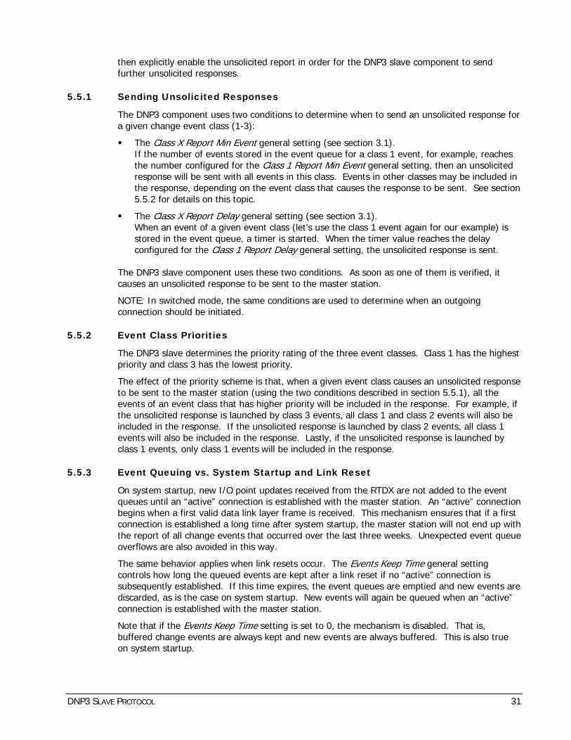
5.5.1 Sending Unsolicited Responses
The DNP3 component uses two conditions to determine when to send an unsolicited response for a given change event class (1-3):
The Class X Report Min Event general setting (see section 3.1). If the number of events stored in the event queue for a class 1 event, for example, reaches the number configured for the Class 1 Report Min Event general setting, then an unsolicited response will be sent with all events in this class. Events in other classes may be included in the response, depending on the event class that causes the response to be sent. See section 5.5.2 for details on this topic.
The Class X Report Delay general setting (see section 3.1). When an event of a given event class (let’s use the class 1 event again for our example) is stored in the event queue, a timer is started. When the timer value reaches the delay configured for the Class 1 Report Delay general setting, the unsolicited response is sent.
The DNP3 slave component uses these two conditions. As soon as one of them is verified, it causes an unsolicited response to be sent to the master station.
NOTE: In switched mode, the same conditions are used to determine when an outgoing connection should be initiated.
5.5.2 Event Class Priorities
The DNP3 slave determines the priority rating of the three event classes. Class 1 has the highest priority and class 3 has the lowest priority.
The effect of the priority scheme is that, when a given event class causes an unsolicited response to be sent to the master station (using the two conditions described in section 5.5.1), all the events of an event class that has higher priority will be included in the response. For example, if the unsolicited response is launched by class 3 events, all class 1 and class 2 events will also be included in the response. If the unsolicited response is launched by class 2 events, all class 1 events will also be included in the response. Lastly, if the unsolicited response is launched by class 1 events, only class 1 events will be included in the response.
5.5.3 Event Queuing vs. System Startup and Link Reset
On system startup, new I/O point updates received from the RTDX are not added to the event queues until an “active” connection is established with the master station. An “active” connection begins when a first valid data link layer frame is received. This mechanism ensures that if a first connection is established a long time after system startup, the master station will not end up with the report of all change events that occurred over the last three weeks. Unexpected event queue overflows are also avoided in this way.
The same behavior applies when link resets occur. The Events Keep Time general setting controls how long the queued events are kept after a link reset if no “active” connection is subsequently established. If this time expires, the event queues are emptied and new events are discarded, as is the case on system startup. New events will again be queued when an “active” connection is established with the master station.
Note that if the Events Keep Time setting is set to 0, the mechanism is disabled. That is, buffered change events are always kept and new events are always buffered. This is also true on system startup.
DNP3 SLAVE PROTOCOL 31

5.6 Output Control Operations
Output control operations on analog or binary output points are initiated by the master station, which sends a control request on the communications link and then waits for a confirmation of the operation.
The DNP3 slave component validates the output control operation received from the master station. Output control operations can therefore be refused for the following reasons:
The command message is erroneous or contains unexpected settings.
The command is inhibited (locally, remotely, etc.).
The requested operation applies to an unknown or non-configured (disabled) point.
The requested output point is currently controlled by another slave component.
The requested output point is not in a valid operational state, i.e., at least one invalid status bit is set.
After all checks have been performed, a command message can potentially be forwarded to the master component that handles output control operations on the specified point. If a message is forwarded, the DNP3 slave then waits for the reply message sent back by the master, indicating whether or not the operation completed successfully. Thereafter, the DNP3 slave component transmits the confirmation to the master station, which completes the control operation.
In all cases, a confirmation is sent back to the initiator of the command, indicating whether or not the operation completed successfully, or was simply refused. Then the control operation is completed.
The sequence of each control operation is recorded through the Command Log Journal (see section 6.1).
5.6.1 Command Confirmation: real and simulated
Depending on the configuration of the output points, the DNP3 slave component asks the master protocol component involved to send the reply message before (simulated) or after the request is forwarded to the remote device (real).
Simulated confirmation should be used when a quick response is required from the master component. This can be the case if the command is to be performed by an RTU that requires a large amount of time to complete the operation.
5.6.2 Analog Output Specific
Analog output control operations are quite simple; only a value and the format of the value are required to build a command that is destined to a master component. An additional check is made to ensure that for a given OPERATE request, the value and its format are as specified in the SELECT request. If not, the request is refused.
The format of the value applied depends on the analog output object variation, which is taken directly from the application layer control request received from the master station. The master component involved may have to convert the value to a format that the end device can handle.
5.6.3 Binary Output Specific
To perform binary output control operations on a given output point, the master station specifies a control function among those defined by in the DNP3 protocol; LATCH ON/OFF, PULSE ON/OFF and TRIP/CLOSE. On the RTDX side, the control functions, called execute types, are normalized as OPEN/CLOSE and PULSE. Consequently, it is the slave component's responsibility to translate the DNP control function to an execute type defined by the RTDX.
32 DNP3 SLAVE PROTOCOL

The translations are performed as follows:
PULSE ON/OFF are translated to PULSE;
TRIP and LATCH OFF are translated to OPEN;
CLOSE and LATCH ON are translated to CLOSE.
Master components are also responsible for translating the RTDX execute types to a protocol-specific operation. With this mechanism, the master station is able to control the output points of any protocol.
For binary output control operations, two additional checks are performed. The first ensures that for a given request, the resulting execute type is supported by the specified output point, based on the configuration of the master protocol responsible for the point. The second ensures that for a given OPERATE request, the control function is the same as that specified in the SELECT request. Requests can also be rejected if the Queue or Clear field of the DNP control relay output block is not 0.
5.6.3.1 TRIP/CLOSE operations using two pulse points
The DNP3 slave provides a mechanism to allow the master station to operate a single master open/close point using two slave points with the PULSE control function.
This mechanism is activated, for a given binary output point, when the Points Pairing binary output setting is set to “Dual Point Open/Close, Open First” or “Dual Point Open/Close, Close First”. In this case, the DNP3 slave component creates a point at the next index, which will handle the complementary operation. If the point is configured as “Dual Point Open/Close, Open First”, it handles OPEN operations, and the complementary point handles CLOSE operations. Inversely, if the point is configured as “Dual Point Open/Close, Close First”, it handles CLOSE operations, and the complementary point handles OPEN operations. Consequently, the index of the complementary point is reserved and cannot be associated with another point.
From the master station point of view, two output points are available to perform control output operations. These two points can be operated using the PULSE control function, which will be translated to an OPEN or CLOSE execute on the configured output point. Moreover, these two points can be operated using TRIP/CLOSE or LATCH ON/OFF control functions. In this case, the control function is translated to an OPEN or CLOSE execute, depending of the Points Pairing setting, and the end operation always applies to the configured output point, regardless of which point the master station is controlling.
For example, if the point at index 8 is configured as “Dual Point, Open First”, the point at index 9 is the complementary point of the pair. From the master station point of view, points 8 and 9 can be operated with a TRIP/CLOSE or LATCH ON/OFF control function. Thus, a TRIP or LATCH OFF operation on point 8 or 9 becomes an OPEN command on point 8, and a CLOSE or LATCH ON operation on point 8 or 9 becomes a CLOSE command on point 9.
5.7 Cold and Warm Restart
The DNP3 protocol provides an application layer Warm Res art function code (013) and a ColdRes art function code (014). These enable the master station to partially or completely restart the DNP3 slave component.
t t
5.7.1 Warm Restart Behavior
Upon receiving the Warm Restart request, the DNP3 slave component sends a response to the master station that includes the warm restart time (2,000 ms). The component is then restarted. All buffers are emptied, but the configuration stays the same. This means that if the master station has sent requests to change an object event class, or changed analog reporting deadband values, these changes are not affected.
DNP3 SLAVE PROTOCOL 33
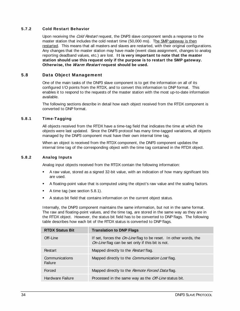
5.7.2 Cold Restart Behavior
Upon receiving the Cold Restart request, the DNP3 slave component sends a response to the master station that includes the cold restart time (50,000 ms). The SMP gateway is then restarted. This means that all masters and slaves are restarted, with their original configurations. Any changes that the master station may have made (event class assignment, changes to analog reporting deadband values, etc.) are lost. It is very important to note that the master station should use this request only if the purpose is to restart the SMP gateway. Otherwise, the Warm Restart request should be used.
5.8 Data Object Management
One of the main tasks of the DNP3 slave component is to get the information on all of its configured I/O points from the RTDX, and to convert this information to DNP format. This enables it to respond to the requests of the master station with the most up-to-date information available.
The following sections describe in detail how each object received from the RTDX component is converted to DNP format.
5.8.1 Time-Tagging
All objects received from the RTDX have a time-tag field that indicates the time at which the objects were last updated. Since the DNP3 protocol has many time-tagged variations, all objects managed by the DNP3 component must have their own internal time tag.
When an object is received from the RTDX component, the DNP3 component updates the internal time tag of the corresponding object with the time tag contained in the RTDX object.
5.8.2 Analog Inputs
Analog input objects received from the RTDX contain the following information:
A raw value, stored as a signed 32-bit value, with an indication of how many significant bits are used.
A floating-point value that is computed using the object’s raw value and the scaling factors.
A time tag (see section 5.8.1).
A status bit field that contains information on the current object status.
Internally, the DNP3 component maintains the same information, but not in the same format. The raw and floating-point values, and the time tag, are stored in the same way as they are in the RTDX object. However, the status bit field has to be converted to DNP flags. The following table describes how each bit of the RTDX status is converted to DNP flags.
RTDX Status Bit Translation to DNP Flags
Off-Line If set, forces the On-Line flag to be reset. In other words, the On-Line flag can be set only if this bit is not.
Restart Mapped directly to the Res art flag. t
Communications Failure
Mapped directly to the Communication Lost flag.
Forced Mapped directly to the Remote Forced Data flag.
Hardware Failure Processed in the same way as the Off-Line status bit.
34 DNP3 SLAVE PROTOCOL

RTDX Status Bit Translation to DNP Flags
Over-Range Mapped directly to the Over-Range flag.
Bad Reference Mapped directly to the Reference Check flag.
Spare Not used.
Table 5-2 Translation of the RTDX status bits to DNP flags for analog inputs
The DNP Local Forced Data flag is always cleared for analog inputs since the component doesn’t allow data to be forced locally.
When the master station sends a request for a 16-bit/32-bit variation of the object, the following equations are used to build the response:
If the Use Float setting does not have a checkmark:
16-bit/32-bit DNP value = (RTDX raw value – Offset) / Scale
If the Use Float setting has a checkmark:
16-bit/32-bit DNP value = (RTDX float value – Offset) / Scale
When the master station sends a request for a floating-point variation of the object, the following equation is used to build the response:
Short Float DNP value = (RTDX float value – Offset) / Scale
5.8.2.1 Analog input event generation
Analog input events can be generated when new information is received from the RTDX. Obviously, if an analog input point is configured with a class 0 event class, no event is generated for this point at any time, at least not until the master station dynamically changes the event class associated with the point.
Events are generated for a given analog input point if at least one of the following conditions is met:
The DNP flags have changed.
The offset between the last reported value and the current value exceeds the deadband value.
The last event reported to the master station was time-tagged locally, and the device time tag is now available.
5.8.2.2 Analog input reporting deadband
When the master station sends a write request to set the deadband value for a given point, it may send the new value as a 16-bit, 32-bit or floating-point value.
Since the analog input reporting deadband is managed internally as a floating-point value, the new deadband value must be calculated if the master sends the new deadband as a 16-bit or 32-bit value. To perform this calculation, the DNP3 component uses the point’s scaling factors. These factors are obtained from the static information that the RTDX component maintains for each I/O point in its database. The floating-point value is calculated as follows:
Deadband value (floating point) = (deadband value (16-bit/32-bit) * scale) + offset
DNP3 SLAVE PROTOCOL 35

The same pattern applies when the master station sends a read request for the deadband value of a given point, requesting the value in either 16-bit or 32-bit format. The 16-bit or 32-bit value is calculated as follows:
Deadband value (16-bit/32-bit) = (deadband value (floating point) – offset) / scale
5.8.3 Binary Inputs
Binary input objects received from the RTDX contain the following information:
A binary state.
A time tag (see section 5.8.1).
A status bit field that contains information on the current status of the object.
Internally, the DNP3 component maintains the same information, but not in the same format. The state and the time tag are stored in the same way as they are in the RTDX object. However, the status bit field has to be converted to DNP flags. The following table describes how each bit of the RTDX status is converted to DNP flags.
RTDX Status Bit Translation to DNP Flags
Off-Line If set, forces the On-Line flag to be reset. In other words, the On-Line flag can be set only if this bit is not.
Restart Mapped directly to the Res art flag. t
Communications Failure
Mapped directly to the Communication Lost flag.
Forced Mapped directly to the Remote Forced Data flag.
Hardware Failure Processed in the same way as the Off-Line status bit.
Over-Range Not used.
Bad Reference Not used.
Spare Not used.
Table 5-3 Translation of the RTDX status bits to DNP flags for binary inputs
The DNP Local Forced Data flag is always cleared for binary input since the component doesn’t allow data to be forced locally. The DNP Chatter Filter flag is also always cleared since the RTDX status doesn’t provide any bit to match this information. The DNP State flag is used to indicate the current state of a binary input point.
5.8.3.1 Binary input event generation
Binary input events can be generated when new information is received from the RTDX. Obviously, if a binary input point is configured with a class 0 event class, no event is generated for this point at any time, at least not until the master station dynamically changes the event class associated with the point.
No special conditions have to be met for a binary event to be generated. Each binary transition or change of status causes an event to be generated. Furthermore, an event is generated if the last event reported to the master station was time-tagged locally and the device time tag is now available.
36 DNP3 SLAVE PROTOCOL

5.8.4 Counter Inputs
Counter input objects are stored as analog input objects in the RTDX. The following information is available for each object:
A raw value, stored as a signed 32-bit value, with an indication of how many significant bits are used.
A floating-point value that is not used, since counter objects can only be reported using 16-bit or 32-bit variations.
A time tag (see section 5.8.1).
A status bit field that contains information about the current object status.
Internally, the DNP3 component maintains the same information, but not in the same format. The raw value is transformed to an unsigned 32-bit value. The time tag is stored in the same format as it is in the RTDX object. However, the status bit field has to be converted to DNP flags. The following table describes how each bit of the RTDX status is converted to DNP flags.
RTDX Status Bit Translation to DNP Flags
Off-Line If set, forces the On-Line flag to be reset. In other words, the On-Line flag can be set only if this bit is not.
Restart Mapped directly to the Res art flag. t
Communications Failure
Mapped directly to the Communication Lost flag.
Forced Mapped directly to the Remote Forced Data flag.
Hardware Failure Processed the same way as the Off-Line status bit.
Over-Range Mapped directly to the Roll-Over flag.
Bad Reference Not used.
Spare Not used.
Table 5-4 Translation of the RTDX status bits to DNP flags for counter inputs
The DNP Local Forced Data flag is always cleared for counter inputs, since the component doesn’t allow data to be forced locally. The translation explained below also applies to frozen counter input points.
Since each counter input has a frozen counter input associated with it, when new information for a given counter input point is received from the RTDX, the associated frozen counter input point also has to be updated. For frozen counter input points, only the DNP flags are updated. This is because by definition, a frozen counter input is used to store the value of a counter input at a given moment, i.e., when the master sends a freeze command.
5.8.4.1 Counter input event generation
Counter input events can be generated when new information is received from the RTDX. Obviously, if a counter input point is configured with a class 0 event class, no event is generated for this point at any time, at least not until the master station dynamically changes the event class associated with the point.
DNP3 SLAVE PROTOCOL 37
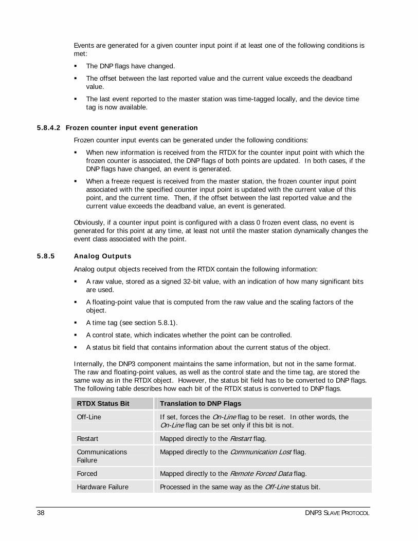
Events are generated for a given counter input point if at least one of the following conditions is met:
The DNP flags have changed.
The offset between the last reported value and the current value exceeds the deadband value.
The last event reported to the master station was time-tagged locally, and the device time tag is now available.
5.8.4.2 Frozen counter input event generation
Frozen counter input events can be generated under the following conditions:
When new information is received from the RTDX for the counter input point with which the frozen counter is associated, the DNP flags of both points are updated. In both cases, if the DNP flags have changed, an event is generated.
When a freeze request is received from the master station, the frozen counter input point associated with the specified counter input point is updated with the current value of this point, and the current time. Then, if the offset between the last reported value and the current value exceeds the deadband value, an event is generated.
Obviously, if a counter input point is configured with a class 0 frozen event class, no event is generated for this point at any time, at least not until the master station dynamically changes the event class associated with the point.
5.8.5 Analog Outputs
Analog output objects received from the RTDX contain the following information:
A raw value, stored as a signed 32-bit value, with an indication of how many significant bits are used.
A floating-point value that is computed from the raw value and the scaling factors of the object.
A time tag (see section 5.8.1).
A control state, which indicates whether the point can be controlled.
A status bit field that contains information about the current status of the object.
Internally, the DNP3 component maintains the same information, but not in the same format. The raw and floating-point values, as well as the control state and the time tag, are stored the same way as in the RTDX object. However, the status bit field has to be converted to DNP flags. The following table describes how each bit of the RTDX status is converted to DNP flags.
RTDX Status Bit Translation to DNP Flags
Off-Line If set, forces the On-Line flag to be reset. In other words, the On-Line flag can be set only if this bit is not.
Restart Mapped directly to the Res art flag. t
Communications Failure
Mapped directly to the Communication Lost flag.
Forced Mapped directly to the Remote Forced Data flag.
Hardware Failure Processed in the same way as the Off-Line status bit.
38 DNP3 SLAVE PROTOCOL

RTDX Status Bit Translation to DNP Flags
Over-Range Not used.
Bad Reference Not used.
Spare Not used.
Table 5-5 Translation of the RTDX status bits to DNP flags for analog outputs
The DNP Local Forced Data flag is always cleared for analog output points, since the component doesn’t allow data to be forced locally.
When the master station sends a request for a 16-bit/32-bit variation of the object, the following equations are used to build the response:
When the Use Float setting does not have a checkmark:
16-bit/32-bit DNP value = (RTDX raw value – Offset) / Scale
When the Use Float setting has a checkmark:
16-bit/32-bit DNP value = (RTDX float value – Offset) / Scale
When the master station sends a request for a floating-point variation of the object, the following equation is used to build the response:
Short Float DNP value = (RTDX float value – Offset) / Scale
5.8.5.1 Analog output control state
The control state of an analog output point is an access lock mechanism that lets the slave component know whether the point is currently “controllable”. In other words, the control state indicates whether the point is ready to accept a control operation.
When a control output request is received from the master station, the DNP3 slave may reject the request if the point is not “controllable”. There can be several reasons for which a point is blocked from control operations. For example, the point is currently controlled by another component, the point is inhibited for maintenance purposes, and so on.
5.8.5.2 Analog output event generation
Analog output events can be generated when new information is received from the RTDX. Obviously, if an analog output point is configured with a class 0 event class, no event is generated for this point at any time, at least not until the master station dynamically changes the event class associated with the point.
Since the DNP3 protocol specification doesn’t define a change event object for analog output information, the object used for event reporting is object 40 – Analog Output Status. The variation used is taken from the 40 Analog Ouput default variation setting (see 3.2).
Events are generated for a given analog input point if at least one of the following conditions is met:
The DNP flags have changed.
The offset between the last reported value and the current value exceeds the deadband value.
DNP3 SLAVE PROTOCOL 39

5.8.6 Binary Outputs
Binary output objects received from the RTDX contain the following information:
A binary state.
A time tag (see section 5.8.1).
A control state, which indicates whether the point can be controlled.
A status bit field that contains information about the current status of the object.
Internally, the DNP3 component maintains the same information, but not in the same format. The state, control state and time tag are stored the same way as they are in the RTDX object. However, the status bit field has to be converted to DNP flags. The following table describes how each bit of the RTDX status is converted to DNP flags.
RTDX Status Bit Translation to DNP Flags
Off-Line If set, forces the On-Line flag to be reset. In other words, the On-Line flag can be set only if this bit is not.
Restart Mapped directly to the Res art flag. t
Communications Failure
Mapped directly to the Communication Lost flag.
Forced Mapped directly to the Remote Forced Data flag.
Hardware Failure Processed in the same way as the Off-Line status bit.
Over-Range Not used.
Bad Reference Not used.
Spare Not used.
Table 5-6 Translation of the RTDX status bits to DNP flags for binary outputs
The DNP Local Forced Data flag is always cleared for binary outputs since the component doesn’t allow data to be forced locally. The DNP State flag is used to indicate the current state of a binary input point.
5.8.6.1 Binary output control state
The control state field for binary output points is used in the same way as it is for analog output points. Refer to section 5.8.5.1 for additional information on this topic.
5.8.6.2 Binary output event generation
Binary output events can be generated when new information is received from the RTDX. Obviously, if a binary input point is configured with a class 0 event class, no event is generated for this point at any time, at least not until the master station dynamically changes the event class associated with the point.
Since the DNP3 protocol specification doesn’t define a change event object for binary output information, the object used for event reporting is object 10 variation 02 – Binary Output Status.
No special conditions have to be met for a binary event to be generated. Each binary transition or change of status causes an event to be generated.
40 DNP3 SLAVE PROTOCOL

5.8.7 Generated Binary Inputs
The DNP3 slave component generates two logical binary inputs:
Name Description
___LinkActive Indicates whether or not the link configured for this protocol instance shows signs of activity.
___LinkAvailable Indicates whether or not the link configured for this protocol instance is operational.
Table 5-7 Generated Binary Inputs
DNP3 SLAVE PROTOCOL 41

6. Diagnostics Diagnostic information is generated by the DNP3 slave component so that you can follow the activities that are going on between the component and the master station. This information is divided into 3 categories: log entries, statistics tables and real-time traces.
6.1 Log Entries
The DNP3 slave maintains at least the following special log entries (entries other than those that all master and slave components support by default):
Log Entries made by the DNP3 slave protocol component
Startup Invalid headers or versions for information found in the configuration files.
Indications of the number of I/O points of each category that should have been configured but were ignored because of errors in the configuration file.
Any problems encountered when establishing links with the various SMP gateway software interfaces.
Any other initialization problems.
An indication that initialization was completed successfully, when applicable.
Command All detailed command-processing related activities, along with a success or failure status for each step.
Protocol Various abnormalities or errors detected when communicating with the master station. To prevent log overflow, only the first occurrence of each type of error since the last link reset is logged, with an “At least one case of….” mention.
Reset All cold restart commands received from the master station, before forcing the system to restart.
Table 6-1 Log Entries
6.2 Statistics Tables
The DNP3 slave maintains various statistics that you can view with the SMP Tools. Most of the information in this table is directly received from or sent to the master station, or taken from the configuration file.
Component statistics are displayed on 3 pages. The statistics of each page are described in the tables below.
6.2.1 Page 1 - Configuration
Name Description
General
Instance Name Indicate the complete instance name.
Link Address See section 3.1 – General Settings.
42 DNP3 SLAVE PROTOCOL

Name Description
Master Link Address See section 3.1 – General Settings.
Inactivity Timeout (s) See section 3.1 – General Settings.
Command enable See section 3.1 – General Settings: Con rol Enabled. t
Selection Timeout (ms) See section 3.1 – General Settings.
Clock Synchro. delay (s) See section 3.1 – General Settings: Need Time Delay.
Unsolicited reporting See section 3.1 – General Settings: Unsolicited Report.
Unsolicited reporting max. retries
See section 3.1 – General Settings: Unsolicited Max Retries.
Unsolicited reporting retry delay (ms)
See section 3.1 – General Settings: Unsolicited Retry Delay.
Unsolicited reporting: Class 1 min. event
See section 3.1 – General Settings: Class 1 Report Min Event.
Unsolicited reporting: Class 2 min. event
See section 3.1 – General Settings: Class 2 Report Min Event.
Unsolicited reporting: Class 3 min. event
See section 3.1 – General Settings: Class 3 Report Min Event.
Unsolicited reporting: Class 1 min. delay (ms)
See section 3.1 – General Settings: Class 1 Report Delay.
Unsolicited reporting: Class 2 min. delay (ms)
See section 3.1 – General Settings: Class 2 Report Delay.
Unsolicited reporting: Class 3 min. delay (ms)
See section 3.1 – General Settings: Class 3 Report Delay.
Data link confirmation mode
See section 3.1 – General Settings: Link Confirmation.
Data link confirmation timeout (ms)
See section 3.1 – General Settings: Link Confirmation Timeout.
Data link max. retries See section 3.1 – General Settings: Link Max Retries.
Application confirmation timeout (ms)
See section 3.1 – General Settings: Applic Confirmation Timeout.
Events Keep Time (s) See section 3.1 – General Settings.
End of initialization timeout (s)
See section 3.1 – General Settings: Max Connection Delay.
Inter-character Maximum Delay (ms)
See section 3.1 – General Settings: Int. Ch. Delay.
Unavailability Timeout (s) See section 3.1 – General Settings.
Default Variations
01: Binary Input See section 3.2 – Default Variation Settings.
DNP3 SLAVE PROTOCOL 43

Name Description
02: Binary Input Change See section 3.2 – Default Variation Settings.
20: Binary Counter See section 3.2 – Default Variation Settings.
21: Frozen Counter See section 3.2 – Default Variation Settings.
22: Counter Change Event See section 3.2 – Default Variation Settings.
23: Frozen Counter Event See section 3.2 – Default Variation Settings.
30: Analog Input See section 3.2 – Default Variation Settings.
32: Analog Change Event See section 3.2 – Default Variation Settings.
34: Analog Input Reporting Deadband
See section 3.2 – Default Variation Settings.
40: Analog Output Status See section 3.2 – Default Variation Settings.
Switched Connection
Enabled See section 3.3 - Switched Connection Settings.
Allow Outgoing Connections
See section 3.3 - Switched Connection Settings.
Maximum Connection Retries
See section 3.3 - Switched Connection Settings.
Retry Delay (ms) See section 3.3 - Switched Connection Settings.
Schedule:
Start Time (min) See section 3.4 - Switched Connection Schedule Settings.
Stop Time (min) See section 3.4 - Switched Connection Schedule Settings.
Cycle (min) See section 3.4 - Switched Connection Schedule Settings.
I/O Points Information
Analog input points configured
Indicates the total number of analog input points configured in the DNP3 slave component.
Analog output points configured
Indicates the total number of analog output points configured in the DNP3 slave component.
Binary input points configured
Indicates the total number of binary input points configured in the DNP3 slave component.
Binary output points configured
Indicates the total number of binary output points configured in the DNP3 slave component.
Running counter points configured
Indicates the total number of counter input points configured in the DNP3 slave component.
Table 6-2 Configuration Page
44 DNP3 SLAVE PROTOCOL

6.2.2 Page 2 - Operations and Protocol Layers Statistics
Name Description
General
Component status Indicates the current status of the component: created, initialized, started, etc.
Communication status Indicates the current status of the communications link: created, initialized, waiting for connection, connected, etc.
Inactivity timeout occurrence
Indicates the number of inactivity timeout occurrences.
Physical Layer
Count of bytes sent Indicates the total number of bytes sent through the communications link.
Count of bytes received Indicates the total number of bytes received through the communications link.
Data Link Layer
Destination address mismatch
Indicates the number of data link frames received with a destination address that doesn’t match the configured link address.
Source address mismatch Indicates the number of data link frames received with a source address that doesn’t match the configured master link address.
CRC errors Indicates the number of data link frames received with a CRC error.
Synchronization errors Indicates the number of data link frames received with a bad synchronization byte.
Length errors Indicates the number of data link frames received with a length field value that doesn’t match the real frame length.
FCB errors Indicates the number of data link frames received with an invalid FCB field value.
Frames received Indicates the total number of data link frames received.
Frames transmitted Indicates the total number of data link frames transmitted.
Transport Layer
Sequence numbers error Indicates the number of transport layer frames received with sequence numbers out of sequence.
Application Layer
DNP3 SLAVE PROTOCOL 45
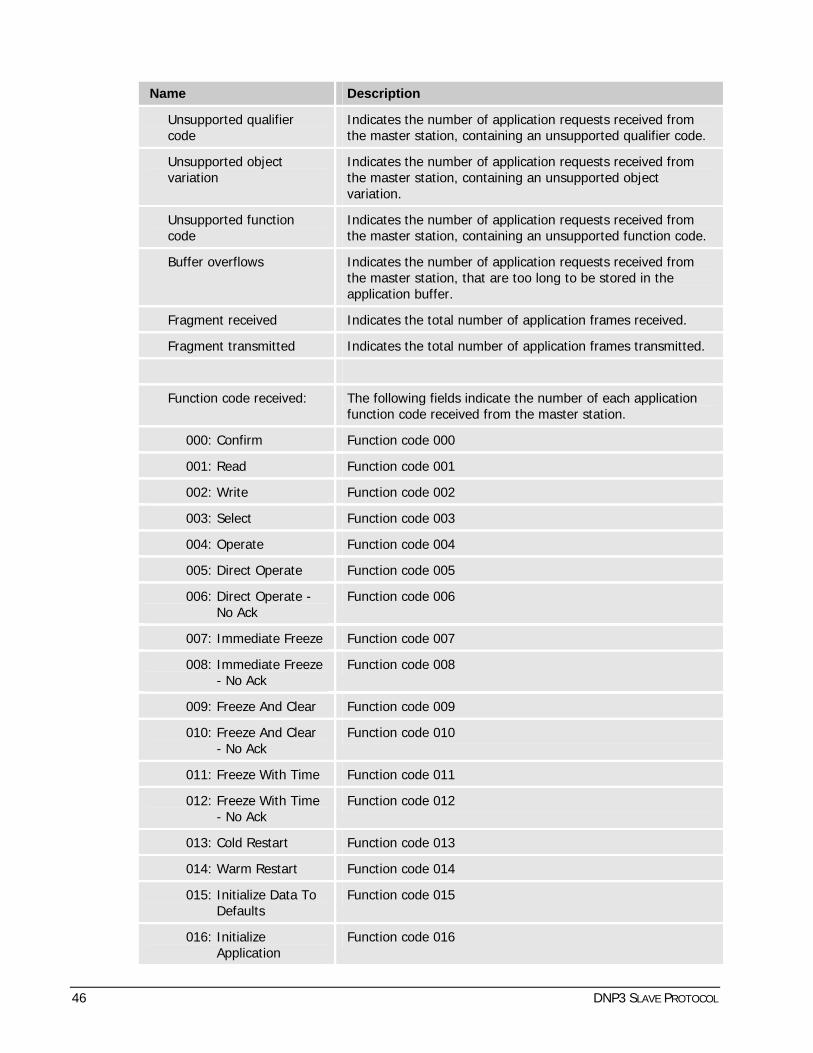
Name Description
Unsupported qualifier code
Indicates the number of application requests received from the master station, containing an unsupported qualifier code.
Unsupported object variation
Indicates the number of application requests received from the master station, containing an unsupported object variation.
Unsupported function code
Indicates the number of application requests received from the master station, containing an unsupported function code.
Buffer overflows Indicates the number of application requests received from the master station, that are too long to be stored in the application buffer.
Fragment received Indicates the total number of application frames received.
Fragment transmitted Indicates the total number of application frames transmitted.
Function code received: The following fields indicate the number of each application function code received from the master station.
000: Confirm Function code 000
001: Read Function code 001
002: Write Function code 002
003: Select Function code 003
004: Operate Function code 004
005: Direct Operate Function code 005
006: Direct Operate - No Ack
Function code 006
007: Immediate Freeze Function code 007
008: Immediate Freeze - No Ack
Function code 008
009: Freeze And Clear Function code 009
010: Freeze And Clear - No Ack
Function code 010
011: Freeze With Time Function code 011
012: Freeze With Time - No Ack
Function code 012
013: Cold Restart Function code 013
014: Warm Restart Function code 014
015: Initialize Data To Defaults
Function code 015
016: Initialize Application
Function code 016
46 DNP3 SLAVE PROTOCOL

Name Description
017: Start Application Function code 017
018: Stop Application Function code 018
019: Save Configuration
Function code 019
020: Enable Unsolicited Messages
Function code 020
021: Disable Unsolicited Messages
Function code 021
022: Assign Class Function code 022
023: Delay Measurement
Function code 023
Function code transmitted:
The following fields indicate the number of each application function code transmitted the master station.
000: Confirm Function code 000
129: Response Function code 129
130: Unsolicited Message
Function code 130
Table 6-3 Operations and Protocol Layer Statistics Page
All statistics on the Operations and Protocol Layer Statistics page can be cleared, except for the status field of the General section.
6.2.3 Page 3 – Switched Connections
This page is available only once a switched connection has been enabled (see section 3.3).
Name Description
Communication status Indicates the current status of the communications link: waiting, not connected, connected, etc.
Current Connection Indicates the direction (incoming or outgoing) of the current connection, if any.
Last Session Result Indicates the result of the last communication session.
Incoming Connections:
Connection Count Indicates the number of incoming connections successfully established since system startup.
Last Connection Time Indicates the date and time at which the last incoming connection was established.
DNP3 SLAVE PROTOCOL 47

Name Description
Outgoing Connections:
Connection Count Indicates the number of outgoing connections successfully established since system startup.
Last Connection Time Indicates the date and time at which the last outgoing connection was established.
Last Attempt Reason Indicates the reason for the last outgoing connection attempt: Startup, Class 1/2/3 Ready, Event with Immediate Report, Schedule, Clock Synchro. Required, etc.
Last Attempt Result Indicates the result of the last outgoing connection attempt (see the Failure Count statistics further down in the table).
Current Connection Reason
Indicates the reason for the current outgoing connection attempt: Startup, Class 1/2/3 Ready, Event with Immediate Report, Schedule, Clock Synchro. Required, etc.
Retry Delay (s) Indicates the remaining delay, in seconds, before the next outgoing connection attempt.
Retries Count Indicates the number of outgoing connection retries for the current connection request.
Retries Count (Total) Indicates the total number of outgoing connection retries made since system startup.
Next Connection Scheduled Time
Indicates the date and time of the next scheduled outgoing connection.
Failure Count: The following fields indicate the number of failures for each outgoing connection attempt condition.
Timeout Number of times no device was available to process the requested connection.
Busy Number of times the link was busy at the remote end.
No response Number of times the remote end did not answer.
Rejected Number of times the connection was rejected or aborted by the remote end.
In use Number of times the link was in use and could not be shared.
Invalid parameter(s) Number of times the communication settings were invalid, resulting in an aborted connection.
Generic failure Number of times another type of failure occurred.
Table 6-4 Switched Connections Page
48 DNP3 SLAVE PROTOCOL

6.3 Real-Time Traces
The DNP3 slave generates detailed trace messages for each layer of the DNP3 protocol. These can be combined with the communications component traces (in hexadecimal characters) and with the System/Real Time Data Exchange traces to monitor all of the component’s activities. All categories of available trace messages and their contents are described in the following table.
Trace Name Contents
General Displays information that does not relate to the protocol layers.
Layer #1: Physical Displays the events related to the communications link (connection/disconnection /failure) and the size of the message received or transmitted. Message contents are not displayed since they already exist in the data link layer trace.
Layer #2: Data Link Displays the data link frames that are exchanged between the component and the master station. This trace is divided into the following sections:
Error: Displays data link errors that occurred during the exchange with the master station. An example would be the reception of a frame with a wrong FCB number.
Rx: Displays data link layer frames received from the master station.
Tx: Displays transport layer frames sent to the master station.
The data link frames are displayed in hexadecimal data block format and interpreted message format, showing each field in the data link header.
Layer #3: Transport Displays the transport layer headers of the frames that are exchanged between the component and the master station. This trace is divided into the following sections:
Error: Displays transport layer errors that occurred during the exchange with the master station. An example would be the reception of a sequence number that was not in sequence with previous sequence numbers.
Rx: Displays transport layer information received from the master station.
Tx: Displays transport layer information sent to the master station.
Layer #4: Application Displays the application layer headers of the frames that are exchanged between the component and master stations. This trace is divided into the following sections:
Error: Displays application layer errors that occurred during the exchange with the master station. Examples would be the reception of an unsupported function code, the reception of an unsupported qualifier code for a given object, etc.
Rx: Displays application layer information received from the master station.
Tx: Displays application layer information sent to the master
DNP3 SLAVE PROTOCOL 49

Trace Name Contents station.
Objects Reported Displays the objects (static data or change event) reported to the master station.
Table 6-5 Trace Messages
6.4 SNMP Traps
SNMP traps are generated by the DNP3 slave component to advise the network management team of problems that occur during the normal operation cycle. The team can then take action based on the seriousness of the problems reported.
Refer to the SMP Gateway User Manual, GUI-00316-00001 T, for details regarding SNMP configuration.
6.4.1 Link Up/Down Trap
An SNMP link down trap indicates that the communication with the master station could not be established, or was established but is now broken.
An SNMP link up trap indicates that the communication with the remote device has been established for at least 5 seconds.
With this mechanism, different kinds of problems can be diagnosed, such as a faulty or badly connected physical cable, a remote device that is configured incorrectly or not powered up, an erroneous communication or network configuration, a very noisy electrical environment that corrupts the data stream, etc.
SNMP link down traps are generated under the following conditions:
The communication with the master station is not established during the 60 seconds following the DNP3 slave component acquisition startup.
The communication is established and then broken. In that case, the link down trap is generated only if a previous link up trap was sent.
The inactivity timeout expires.
SNMP link up traps are generated only when communication with the remote device is established for at least 5 seconds.
Once a link down trap has been thrown, subsequent traps will be generated only if the communication is established and a link up trap is sent, followed by a communication breakdown. Thus, an SNMP client won’t be notified more than once for a single communication failure.
The same applies to link up traps, i.e., subsequent traps will be generated only if the communication is broken and a link down trap is sent, after which the communication is established and maintained for at least 5 seconds.
The link up/down trap mechanism is automatically suspended if the acquisition is disabled, either by a logical command or by a pass-thru connection. The link up/down trap mechanism is automatically restarted when the acquisition is resumed by the same means.
50 DNP3 SLAVE PROTOCOL


