Embed Size (px)
Citation preview

2CS
G44
5001
D02
02DMTME-962CSG133030R4022M204675
DMTME-I-485-962CSG163030R4022M204685
GB Operation and assembly instructions

2
DMTME-96: three-phase multimeter for panel mounting, used also in single-phase networks, with 4 red leds displays for the measurement of the mainelectric quantities (including max/min/mean values of some electricalparameters). All the electric quantities can be displayed by pressing thecorresponding scan keys.
DMTME-I-485-96: multimeter for panel mounting with the same characteristicsas the previous model, but with a RS485 serial interface (with galvanicinsulation) and two outputs for use either to generate pulses proportional tothe count of active and reactive energy consumption, or to generate alarmson the main electrical parameters being measured. This instrument is idealfor the realization of monitoring networks and for the storage of the differentconsumption levels.
Main functions• Scan of the measures and indication of the electric quantity, displayed by
the switching on of the corresponding LED
• Dimensions: 96x96 mm
• True RMS measurements
• High accuracy of the measurements thanks to “oversampling’’ techniquesand automatic calibration processes
• 68 total measurements with power analyser functions
• Possibility to select from the setup menu the “default displayed page’’,visualized after about 1 minute of inactivity
• Automatic detection of CTs current flow direction
Only for the DMTME-I-485-96 model
• Generation Two outputs, for use either to generate pulses proportional tothe count of active and reactive three-phase energy and proportional toan energy consumption which can be selected by the user, or to generatesingle-threshold alarms on the main electrical parameters being measured.
• RS485 serial interface

92
92
103
90
13
1
2
a) Introduce the instrument into the hole on the panel to have instrumentbezel striking the panel
b) Fit the red clips into the casing slots [1]
c) Push clips fully inside [2] to have instrument bezel tightly striking the panel,so that clips are locked into the knurled section of the case (to unlock theclips, pull their vertical tab outwards; the detent will be released from theknurled section and clips are moved into the case slots)
Assembly instructions
3

4
Examples of connections
LV three-phase connection with neutral
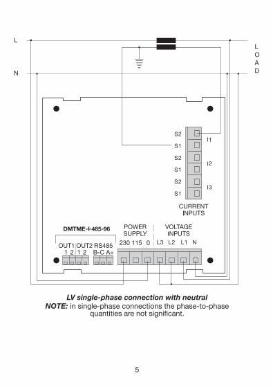
LV single-phase connection with neutralNOTE: in single-phase connections the phase-to-phase
quantities are not significant.
5

Three-phase connection without neutral, with 2TA and 2TV
6

Pin Description Pin Description Pin DescriptionPower Voltage CurrentSupply Inputs Inputs
0 0 ~ alim. S2-I1 S2 – input I1 N N – Voltmeter inp.
115 115 ~ alim. S1-I1 S1 – input I1 L1 L1 – Voltmeter inp.
230 230 ~ alim. S2-I2 S2 – input I2 L2 L2 – Voltmeter inp.
S1-I2 S1 – input I2 L3 L3 – Voltmeter inp.
S2-I3 S2 – input I3
S1-I3 S1 – input I3
NOTE: CURRENT INPUTS connector consists of a pull-out terminal that canbe screw-locked onto the instrument; therefore, the terminal board shouldbe locked after installation to prevent that it is accidentally removed.
Terminal size: 2,5 mm2 (except for RS485 and OUT1 and OUT2 outputs).
Terminal board connections
7
(*) Terminals A+, B-, C, OUT1-1, OUT1-2, OUT2-1 AND OUT 2-2 are meaningful only for the DMTME-I-485-96 model.
Pin Description Pin DescriptionRS485 OUT1-OUT2
A+ (*) A (+) RS485 OUT1-1 (*) Pin 1 pulse Output 1
B- (*) B (-) RS485 OUT1-2 (*) Pin 2 pulse Output 1
C (*) Shield OUT2-1 (*) Pin 1 pulse Output 2
OUT2-2 (*) Pin 2 pulse Output 2

- ➊ L1, L2, L3 Display for the visualization of the electrical parameters ofeach single phase, of the energy counters and time counters (energy andtime counters values are viewed in ascending sequence on L1, L2 and L3displays). The lighting point, on the right of the third display (L3), flashesduring the RS485 communication (only for the DMTME-I-485-96 model)
- ➋ 4th display for the visualization of the electrical parameters of the three-phase system
- ➌ Key for the scan of the electrical parameters of each single phase andof the energy counters, visualized on the L1, L2, L3 displays (➊), if youpress it and hold down, the previous page will be displayed
8
Instrument description

- ➍ Key for the scan of the three-phase electrical parameters, visualized onthe 4th display (➋) and of the time counters, if you press it and hold down,the previous page will be displayed
- ➎ 9 LEDs for the identification of the electrical parameters displayed onthe first three L1, L2, L3 displays (➊)
- ➏ 7 LEDs for the identification of the electrical parameters displayed onthe 4th display (➋)
- ➐ Key for the set up of the display of the electrical parameters maximumvalues (LED MAX ➒ switched on), minimum values (LED MIN ➒ switchedon) and mean values – calculated on a time interval of 15 minutes -(AVERAGE, LED MIN and MAX ➒ switched on simultaneously). When theLED showing the selected type of visualization is switched on, it will bepossible to scan in sequence the different electrical parameters by pressing➌ and ➍ keys
- ➑ LED for the identification of the electrical parameters scale displayedon both instrument’s displays ➊ and ➋ ( K factors= kilo, parameter x 1.000,M = mega, parameter x 1.000.000)
- ➒ LED for the identification of the max/min/mean values visualized on thedisplays ➊ and ➋
- ➌ + ➐ By pressing these keys together, it will be possible to enter theconfiguration menu (setup)
Instrument configuration menu (setup)To enter the instrument configuration menu press ➌ and ➐ keys simultaneously,when the writing “SETUP” is visualized on the first three displays, press the➍ key.
- In the configuration menu the keys have the following function:
- ➌ Increases the selected parameter (fast scroll if hold down); in the resetpages it allows the reset of the selected parameters
- ➐ Decreases the selected parameter (fast scroll if hold down)
- ➍ Confirms the modification and steps to the next page; if you press itand hold down the previous page will be displayed
9

The displayed pages (in sequence) in the configuration menu are the following:
- “Ct rAt”: setting of the CTs (KA) transformation ratio, variable in the range1 ÷ 1250, factory default value 1. For example if you have a 800/5A CT,you must enter the value 160
- “Ut rAt”: setting of the VTs (KV) transformation ratio, variable in the range1 ÷ 500, factory default value 1
- “PULSE” only for DMTME-I-485-96 model: possible values 10, 100, 1.00K(1000) or 10.0K (10000)Wh/pulse (VArh/pulse), factory default value 10.Output O1 = kWh count, output O2 = kVArh count. Active pulses only onoutputs where the alarms function is disabled (dO1 = OFF, dO2 = OFF)
- “dO1 ALr”: only for DMTME-I-485-96 model: selection of the quantity forthe alarm relating to output O1; OFF = alarm disabled (default). Selectedquantities also identified by corresponding led coming on. HI = topthreshold exceeded, LO = bottom threshold exceeded. Example: dO1 HIL1 (led VL-N on) = alarm tripped on phase voltage L1 (VL1-N) when valuemeasured is higher than preset threshold- “dO1 th”: threshold setting for selected quantity- “dO1 dLy”: setting for delay in seconds for enabling (and resetting) outputO1 after an alarm has occurred, default 10
- “dO2 ALr”: only for DMTME-I-485-96 model: selection of the quantity forthe alarm relating to output O2; OFF = alarm disabled (default). Selectedquantities also identified by corresponding led coming on. HI = topthreshold exceeded, LO = bottom threshold exceeded. Example: dO2 HIL1 (led VL-N on) = alarm tripped on phase voltage L1 (VL1-N) when valuemeasured is higher than preset threshold- “dO2 th”: threshold setting for selected quantity- “dO2 dLy”: setting for delay in seconds for enabling (and resetting) outputO2 after an alarm has occurred, default 10
- “PrOt” only for DMTME-I-485-96 model: selection of the communicationprotocol for the RS485 serial interface; 0 = ASCII protocol (reserved forinternal use only), 1 = Modbus-RTU protocol, factory default value 1
- “Id Adr” only for DMTME-I-485-96 model: instrument address for thecommunication with the RS485 serial interface, variable in the range 1 ÷ 247(Modbus-RTU protocol) and 1 ÷ 98 (ASCII protocol), factory default value 31
10

11
- “bAUd” only for DMTME-I-485-96 model: communication speed of theRS485 serial interface; it is possible to set the following values: 2.4, 4.8,9.6, 19.2, where the numeric values correspond respectively to 2400bps,4800bps, 9600bps and 19200bps, factory default value 9600bps (8 bit)
- “PArItY” only for DMTME-I-485-96 model: it is possible to set the followingvalues: O = odd, E = even, n = none; factory default value n
- “StOP” only for DMTME-I-485-96 model: stop bits; it is possible to set thefollowing values: 1, 2 (with Parity = n), 1 (with Parity = O, E, n); factorydefault value 1
- “PAG 1.2.3.” and “PAG 4.”: setting of the default displayed page number,0 ÷ 15 on the first three displays, factory default value 1 and 0 ÷ 7 on the4th display, factory default value 1; 0 = it remains the last selected page
- “t2”: setting (in hours) of the count-down value of the t2 hours counter,factory default value 8760.00 (1 year)
- “rESEt PEA” (PEAK = Peak Values): reset of the maximum and minimumvalues (to reset see note below)
- “rESEt AUG” (AVG = Average): reset of the mean values (to reset see notebelow)
- “rESEt En” (En = Energies): reset of the energy counters (to reset see notebelow)
- “rESEt t1”: reset of the t1 hours counter (to reset see note below)
- “rESEt ALL”: restores the default configurations and resets all parameters(min/max values, mean values, energies, t1 counter) - to reset see notebelow-
- “rEL”: revision of the instrument firmware
NOTE:- to perform the above mentioned resets, on the corresponding page, press
and hold down for some seconds the➌ key until the “-C- -L- -r-” writingappears on the first three displays.
- the peak values, the mean values, the energy counters value and the valueof the t1 and t2 counters are stored in the instrument’s memory also incase of power failure.

NOTE: In case, on the first installation or further to wrong operations or particular events or due to a faultynon-volatile memory (E2prom), the instrument should stop and show a page visualizing, on the first threedisplays, the “INI” writing followed by an internal identification code, press any key to reset the defaultparameters, which may be changed by the user as required.
12
Measured electric quantities(The indication Σ is referred to the three-phase measurement of the considered electric quantity)
Voltage between phases (VL-L)Phase and three-phase system voltage (VL-N and ΣV)Phase and three-phase system current (A and ΣA)FrequencyPhase and three-phase system active power (W and ΣW)Phase and three-phase system reactive power (VAr and ΣVAr)Phase and three-phase system apparent power (VA and ΣVA)Power factor/phase and three-phase system cosφ, withrelevant conventional sign (+ = Inductive, - = Capacitive)Phase and 3-phase system active and reactive energy counters(phase-to-phase view on displays L1, L2 and L3)
DISPLAYED MAX. VALUESPhase voltage (VL-N)Phase current (A)Phase and three-phase system active power (W and ΣW)Phase and three-phase system reactive power (VAr and ΣVAr)Phase and three-phase system apparent power (VA and ΣVA)
DISPLAYED MIN. VALUESPhase voltage (VL-N)Phase current (A)Three-phase active power (ΣW)Three-phase reactive power (ΣVAr)Three-phase apparent power (ΣVA)
DISPLAYED MEAN VALUES (INTEGRATION PERIOD 15 MINUTES)Phase and three-phase system active power (W and ΣW)Phase and three-phase system reactive power (VAr and ΣVAr)Phase and three-phase system apparent power (VA and ΣVA)
TIME COUNTERS (continuous viewing on L1, L2 and L3 displays)“Free-running” hours counter (hours and minutes); it can be reset from the setup menu“Count-down” hours counter (hours and minutes) for maintenance reminder (when the counter reacheszero, it shows negative values, indicating the delay time from the programmed expiry time).
QUANTITIES SELECTABLE FOR ALARMS (only applicable to DMTME-I-485-96)Phase-to-phase voltage (VL-L)Phase and 3-phase system voltage (VL-N and ΣV)Phase and 3-phase system current (A and ΣA)Phase and 3-phase system active power (W and ΣW)Phase and 3-phase system reactive power (VAr and ΣVAr)Phase and 3-phase system apparent power (VA and ΣVA)Phase and 3-phase system power factor (cosφ)“Count-down” hour counter
VL1-L2, VL2-L3, VL3-L1
VL1-N, VL2-N, VL3-N, ΣVI1, I2, I3, ΣIHzW1, W2, W3, ΣWVAr1, VAr2, VAr3, ΣVArVA1, VA2, VA3, ΣVAPF1, PF2, PF3, ΣPF
KWh-L1, KWh-L2, KWh-L3, ΣkWh-3P,KVArh-L1, KVArh-L2, KVArh-L3, ΣkVArh-3P
VL1-N, VL2-N, VL3-N (MAX)I1, I2, I3 (MAX)W1, W2, W3, ΣW (MAX)VAr1, VAr2, VAr3, ΣVAr (MAX)VA1, VA2, VA3, ΣVA (MAX)
VL1-N, VL2-N, VL3-N (MIN)I1, I2, I3 (MIN)ΣW (MIN)ΣVAr (MIN)ΣVA (MIN)
W1, W2, W3, ΣW (AVG)VAr1, VAr2, VAr3, ΣVAr (AVG)VA1, VA2, VA3, ΣVA (AVG)
VL1-L2, VL2-L3, VL3-L1
VL1-N, VL2-N, VL3-N, ΣVI1, I2, I3, ΣIW1, W2, W3, ΣWVAr1, VAr2, VAr3, ΣVArVA1, VA2, VA3, ΣVAPF1, PF2, PF3, ΣPF

Technical characteristicsDIMENSIONS AND WEIGHTDimension 96 mm x 96 mm x 103 mm (LxHxW),
IEC 61554g 005 tuobAthgieW
PROTECTION IP50 on the front panel, IP20 on the terminal boards
POWER SUPPLYycneuqerFegatloV Power Consumption Fuse
230V rms (+15% -10%)240V rms (+10% -15%)115V rms (+15% -10%)
45 ÷ 65Hz < 6VA Fit external fuse 0,1A
120V rms (+10% -15%)
VOLTMETER INPUTS 01egnaR ÷ 500V rms (L-N)
smr V055eulav evitcurtsed-non xaM8MΩ naht retaerGecnadepmi tupni N-L
AMMETER INPUTS (USE ALWAYS EXTERNAL CTs) Am05egnaR ÷ 5A rms
Overload 1,1 permanentMax dispersed power 1,4VA (with Imax = 5A rms, for each phase input)Type of measurement Current measurement by internal shunts, using external CTsDirection of CTs current Detection and automatic adjustment at power up, independent for each phase
DIGITAL OUTPUTSPulse duration: 50ms OFF (min)/50ms ON Max frequency: 10 pulses/secVmax on contact: 48V (peak DC or AC) Imax on contact: 100mA (peak DC or AC)
xamV057 :noitalosIWm054 :elbatapissid xamW
ACCURACY OF THE MEASUREMENTVoltage ±0,5% F.S. ±1 digit in the range 10Vac÷500Vac rms VL-NCurrent ±0,5% F.S. ±1 digit in the range 50mA÷5A rmsActive power ±1% ±0,1% F.S. (from cosφ= 0,3 Ind. to cosφ= -0,3 Cap.)Frequency 40.0 ÷ 99.9Hz: ±0,2% ±0,1Hz
100 ÷ 500Hz: ±0,2% ±1Hz
ENERGY COUNTMaximum value for the single-and three-phase energy 4294,9 MWh (MVArh) with KA = KV = 1
1 ssalCycaruccA
OPERATIVE CONDITIONS0erutarepmet gnitarepO °C ÷ 50°C
01-erutarepmet egarotS °C ÷ 60°C04 ta )esnednoc tuohtiw( .xam %09ytidimuh evitaleR °C
NORMATIVE REFERENCESELECTRICAL SAFETYEC directive No. 73/23/CEE regarding ‘’Low Voltage’’ (Low-Voltage Directive)ELECTROMAGNETIC COMPATIBILITYEC directive No. 89/336/CEE regarding the “Electromagnetic Compatibility’”
13

PARAMETERSVT transformation ratioCT transformation ratioPulses programmingvalue (1)
Quantities selectable for alarm on outputOUT1 and/or OUT2 (1)
Alarm threshold for outputs OUT1and/or OUT2 relating to the selectedquantity (1)
Delay for enabling output OUT1 and/orOUT2 in the event of an alarm (1)
Type of serial protocole (1)
Analyzer’s address (1)
Baud rate for the RS485serial interface line (1)
Parity for the RS485serial interface line (1)
Stop bits for the RS485serial interface line (1)
PAG 1.2.3.(default page of the first three displays)PAG 4. (default page of the 4th display)
“Free-running” counterhours and minutes - t1
“Count-down” counterhours and minutes - t2Calculation period for mean values
POSSIBLE VALUES1 ÷ 5001 ÷ 125010, 100, 1.000, 10.000 Wh/imp(VArh/imp)OFF, V12, V23, V31, VL1-N, VL2-N, VL3-N, ΣV, I1, I2, I3, ΣI, W1, W2, W3, ΣW,VAr1, VAr2, VAr3, ΣVAr, VA1, VA2, VA3,ΣVA, PF1, PF2, PF3, ΣPF, counter t2(OFF = alarm disabled)Depending on measurement range ofselected quantity
1 ÷ 900 (seconds)
0 = ASCII reserved for internal use only1 = Modbus-RTUASCII Prot.: 1 ÷ 98Modbus-RTU Prot.: 1 ÷ 2472.4, 4.8, 9.6, 19.2(es. 9.6 is related to 9600bit/s)O = odd, E = even, n = none
1, 2 (with Parity = n),1 (with Parity = O, E, n)0 ÷ 15(0 = it remains the last displayed page)0 ÷ 7(0 = it remains the last displayed page)The counter can be reset from theconfiguration menu
Starting setting in hours:1 ÷ 32000 (3,5 anni circa)-
FACTORY DEFAULT1110
OFF
Approx. half the fullscale of the selectedquantity10
1
31
9.6
n
1
1
1
The counter works in therange: 0 ÷ 10000000(hours) (about 1140 years)8760 hours(1 year)15 minutes
Rev. D (for Firmware rel. 1.13 and higher)
In consideration of the evolution of the standards and products, the company reserves theright to modify at any time the features of the product described in this literature,we recommend therefore to always verify them beforehand.
ABB S.p.A. - ABB SACE DivisionV.le dell’Industria, 1820010 Vittuone (MI) – ItalyTel. +39 02 9034 1Fax +39 02 9034 7609
Configuration menu
(1) only for DMTME-I-485-96 model