Embed Size (px)
Citation preview

DMT Manual Version 2.0
December 4, 2006
1717 Louisiana NE
Suite 202 Albuquerque, NM 87110
(505) 268-4742 [email protected]
2
Table of Contents
Introduction…………………………………………………………...4 What DMT Does……………………………………………………….5 How A Membrane Deformable Mirror Works……………………..6 How DMT Works……………………………………………………..7 DMT Layout………………………………………………………….9 Mirror Setup………………………………………...……………….10 Control Panel…………………………………………………………11 DMT Output………………………………………………………....21 Running DMT………………………………………………………..22 How Pattern Player™ Works……………………………………….28 Pattern Visualization with DMO™…………………………………29
Figures DMT Main Screen……………………………………………………..4 Unifi Deformable Mirror………………………………………………5 Cross-Section of a Membrane Deformable Mirror…………………..6 OPD before tare removal………………………………………………7 The tare that was removed…………………………………………….8 The OPD with tare removed…………………………………………..8 DMT Layout…………………………………………………………...9 Mirror Setup Screen………………………………………………….10 The Patterns Tab……………………………………………………....11 The Settings Tab……………………………………………………….14 The Pattern Manipulations Tab………………………………………16 The Custom OPDs 1 Tab……………………………………...………18 The Custom OPDs 2 Tab………………………………………….…..19 Sample OPD file output from DMT………………………………….21 DMT started for the first time……………………………………….22 DMT Settings selected………………………………………………..22 Mirror Setup Window…………………………………………..……23 Mirrors successfully loaded………...………………………………..23 Main Window with Mirror Loaded…………………………………24 The Patterns tab once again.…………………………………………24 Browsing for an OPD file…………………………………………….25 Calculating the Influence Function…………………………………..25 Voltage patterns calculated…………………………………………...26
(505) 268-4742 v. 2.0 November 22, 2006
3
Selecting a pattern to view………………………………………….....26 Saving your new pattern file………………………………………….27 Playing a pattern on Pattern Player™……………………………….27 Pattern Player™ Capabilities…………………………………………28 DMO™ and what it shows you……………………………………….29 Opening the Pattern Library…………………………………………30 Opening a pattern file…………………………………………………30 Selecting and loading a pattern using the Pattern Library…………31
(505) 268-4742 v. 2.0 November 22, 2006
4
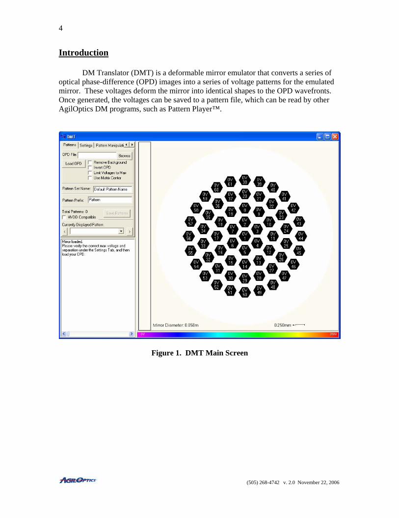
Introduction DM Translator (DMT) is a deformable mirror emulator that converts a series of optical phase-difference (OPD) images into a series of voltage patterns for the emulated mirror. These voltages deform the mirror into identical shapes to the OPD wavefronts. Once generated, the voltages can be saved to a pattern file, which can be read by other AgilOptics DM programs, such as Pattern Player™.
Figure 1. DMT Main Screen
(505) 268-4742 v. 2.0 November 22, 2006
5
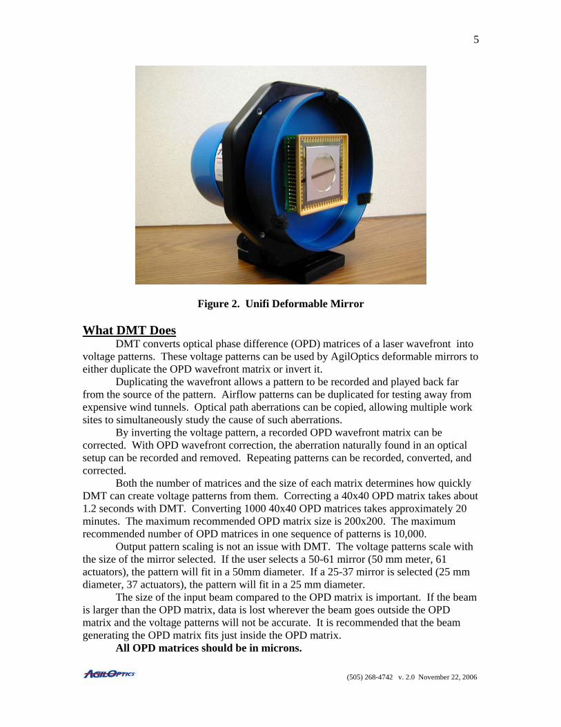
Figure 2. Unifi Deformable Mirror
What DMT Does DMT converts optical phase difference (OPD) matrices of a laser wavefront into voltage patterns. These voltage patterns can be used by AgilOptics deformable mirrors to either duplicate the OPD wavefront matrix or invert it. Duplicating the wavefront allows a pattern to be recorded and played back far from the source of the pattern. Airflow patterns can be duplicated for testing away from expensive wind tunnels. Optical path aberrations can be copied, allowing multiple work sites to simultaneously study the cause of such aberrations. By inverting the voltage pattern, a recorded OPD wavefront matrix can be corrected. With OPD wavefront correction, the aberration naturally found in an optical setup can be recorded and removed. Repeating patterns can be recorded, converted, and corrected. Both the number of matrices and the size of each matrix determines how quickly DMT can create voltage patterns from them. Correcting a 40x40 OPD matrix takes about 1.2 seconds with DMT. Converting 1000 40x40 OPD matrices takes approximately 20 minutes. The maximum recommended OPD matrix size is 200x200. The maximum recommended number of OPD matrices in one sequence of patterns is 10,000.
Output pattern scaling is not an issue with DMT. The voltage patterns scale with the size of the mirror selected. If the user selects a 50-61 mirror (50 mm meter, 61 actuators), the pattern will fit in a 50mm diameter. If a 25-37 mirror is selected (25 mm diameter, 37 actuators), the pattern will fit in a 25 mm diameter.
The size of the input beam compared to the OPD matrix is important. If the beam is larger than the OPD matrix, data is lost wherever the beam goes outside the OPD matrix and the voltage patterns will not be accurate. It is recommended that the beam generating the OPD matrix fits just inside the OPD matrix.
All OPD matrices should be in microns.
(505) 268-4742 v. 2.0 November 22, 2006
6
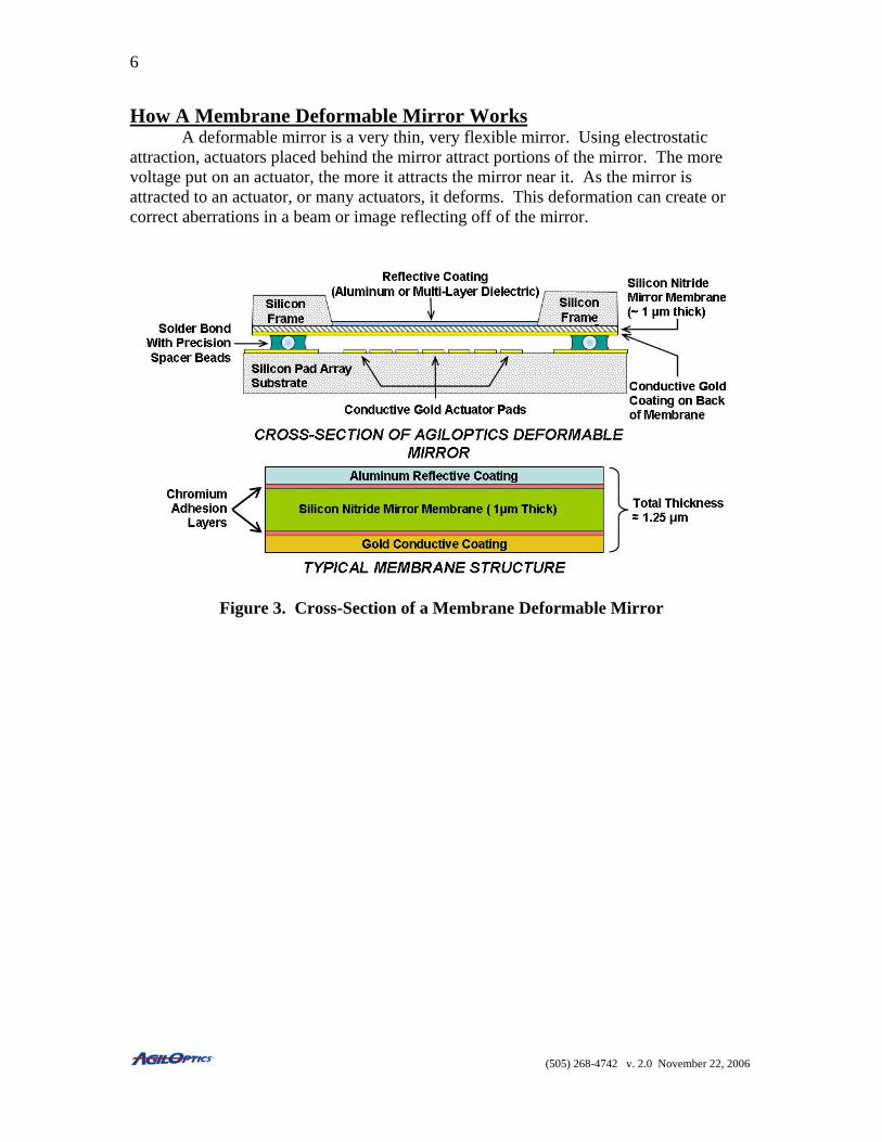
How A Membrane Deformable Mirror Works A deformable mirror is a very thin, very flexible mirror. Using electrostatic attraction, actuators placed behind the mirror attract portions of the mirror. The more voltage put on an actuator, the more it attracts the mirror near it. As the mirror is attracted to an actuator, or many actuators, it deforms. This deformation can create or correct aberrations in a beam or image reflecting off of the mirror.
Figure 3. Cross-Section of a Membrane Deformable Mirror
(505) 268-4742 v. 2.0 November 22, 2006
7
How DMT Works
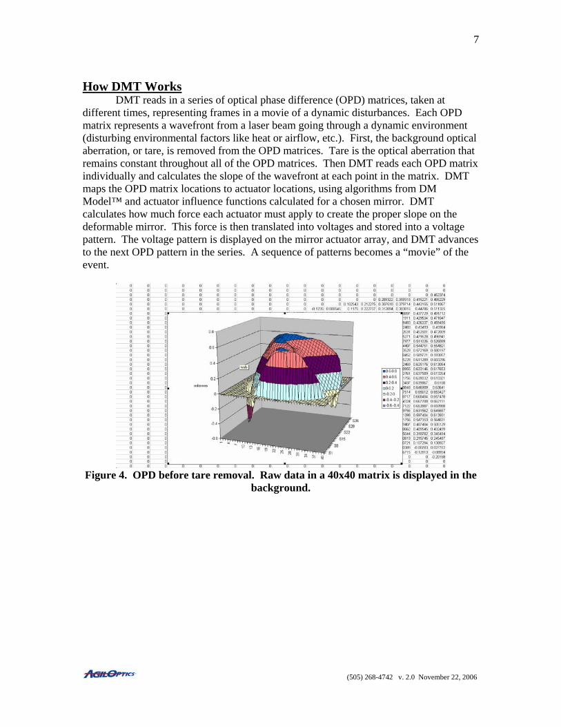
DMT reads in a series of optical phase difference (OPD) matrices, taken at different times, representing frames in a movie of a dynamic disturbances. Each OPD matrix represents a wavefront from a laser beam going through a dynamic environment (disturbing environmental factors like heat or airflow, etc.). First, the background optical aberration, or tare, is removed from the OPD matrices. Tare is the optical aberration that remains constant throughout all of the OPD matrices. Then DMT reads each OPD matrix individually and calculates the slope of the wavefront at each point in the matrix. DMT maps the OPD matrix locations to actuator locations, using algorithms from DM Model™ and actuator influence functions calculated for a chosen mirror. DMT calculates how much force each actuator must apply to create the proper slope on the deformable mirror. This force is then translated into voltages and stored into a voltage pattern. The voltage pattern is displayed on the mirror actuator array, and DMT advances to the next OPD pattern in the series. A sequence of patterns becomes a “movie” of the event.
Figure 4. OPD before tare removal. Raw data in a 40x40 matrix is displayed in the
background.
(505) 268-4742 v. 2.0 November 22, 2006
8
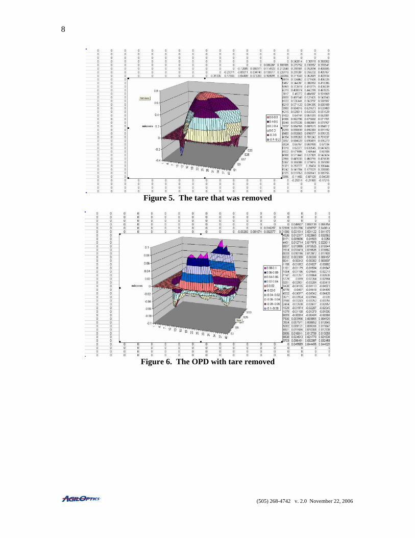
Figure 5. The tare that was removed
Figure 6. The OPD with tare removed
(505) 268-4742 v. 2.0 November 22, 2006
9
DMT Layout
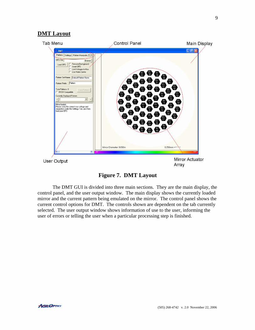
Figure 7. DMT Layout
The DMT GUI is divided into three main sections. They are the main display, the
control panel, and the user output window. The main display shows the currently loaded mirror and the current pattern being emulated on the mirror. The control panel shows the current control options for DMT. The controls shown are dependent on the tab currently selected. The user output window shows information of use to the user, informing the user of errors or telling the user when a particular processing step is finished.
(505) 268-4742 v. 2.0 November 22, 2006
10
Mirror Setup
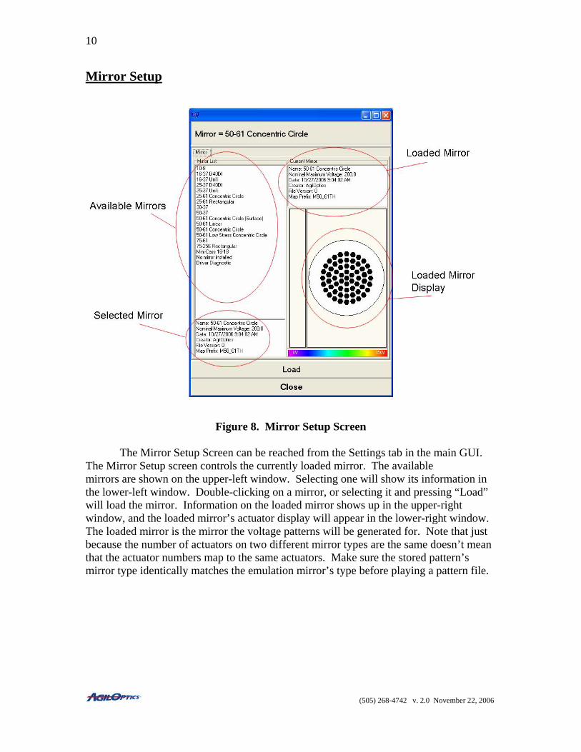
Figure 8. Mirror Setup Screen The Mirror Setup Screen can be reached from the Settings tab in the main GUI.
The Mirror Setup screen controls the currently loaded mirror. The available mirrors are shown on the upper-left window. Selecting one will show its information in the lower-left window. Double-clicking on a mirror, or selecting it and pressing “Load” will load the mirror. Information on the loaded mirror shows up in the upper-right window, and the loaded mirror’s actuator display will appear in the lower-right window. The loaded mirror is the mirror the voltage patterns will be generated for. Note that just because the number of actuators on two different mirror types are the same doesn’t mean that the actuator numbers map to the same actuators. Make sure the stored pattern’s mirror type identically matches the emulation mirror’s type before playing a pattern file.
(505) 268-4742 v. 2.0 November 22, 2006
11
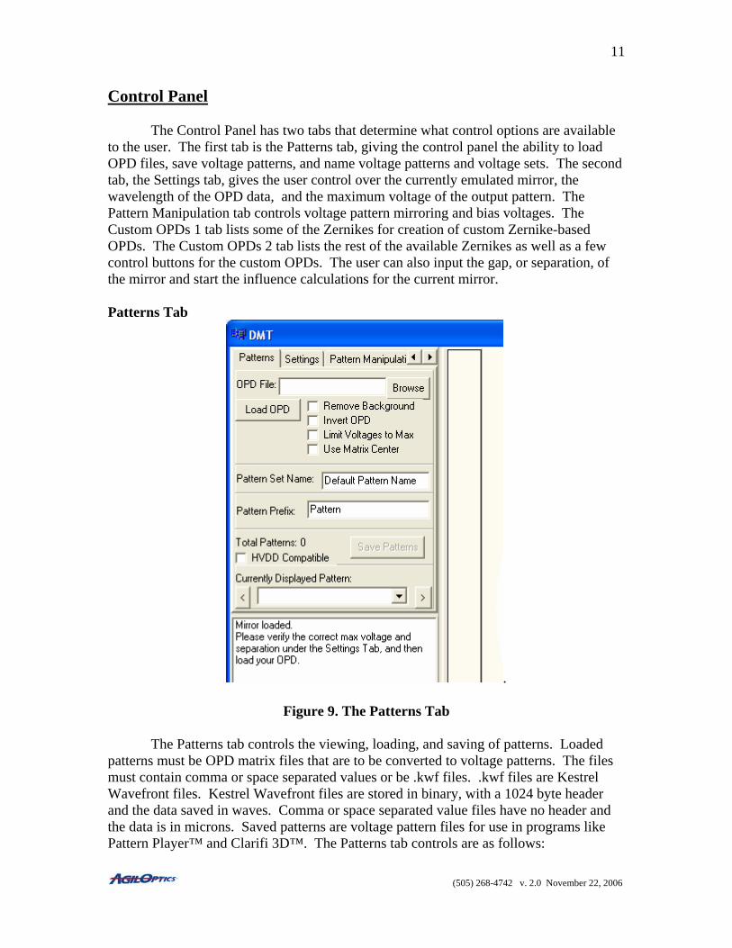
Control Panel The Control Panel has two tabs that determine what control options are available to the user. The first tab is the Patterns tab, giving the control panel the ability to load OPD files, save voltage patterns, and name voltage patterns and voltage sets. The second tab, the Settings tab, gives the user control over the currently emulated mirror, the wavelength of the OPD data, and the maximum voltage of the output pattern. The Pattern Manipulation tab controls voltage pattern mirroring and bias voltages. The Custom OPDs 1 tab lists some of the Zernikes for creation of custom Zernike-based OPDs. The Custom OPDs 2 tab lists the rest of the available Zernikes as well as a few control buttons for the custom OPDs. The user can also input the gap, or separation, of the mirror and start the influence calculations for the current mirror. Patterns Tab
.
Figure 9. The Patterns Tab The Patterns tab controls the viewing, loading, and saving of patterns. Loaded patterns must be OPD matrix files that are to be converted to voltage patterns. The files must contain comma or space separated values or be .kwf files. .kwf files are Kestrel Wavefront files. Kestrel Wavefront files are stored in binary, with a 1024 byte header and the data saved in waves. Comma or space separated value files have no header and the data is in microns. Saved patterns are voltage pattern files for use in programs like Pattern Player™ and Clarifi 3D™. The Patterns tab controls are as follows:
(505) 268-4742 v. 2.0 November 22, 2006
12
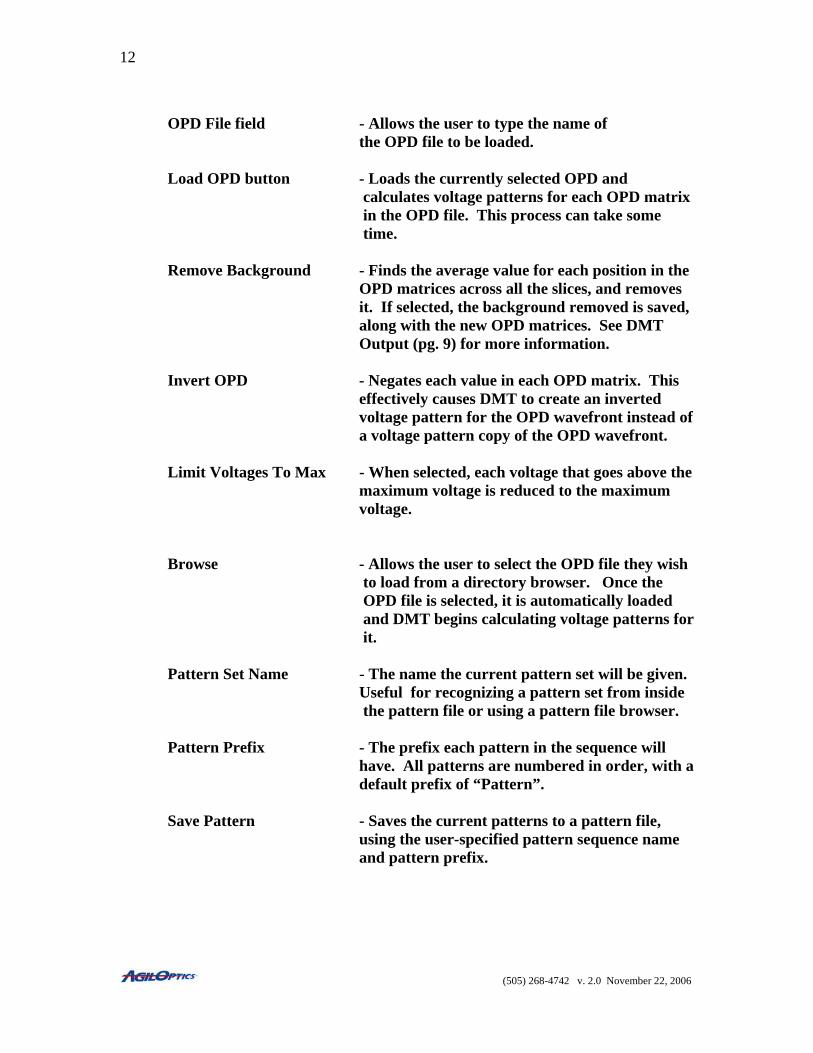
OPD File field - Allows the user to type the name of the OPD file to be loaded. Load OPD button - Loads the currently selected OPD and
calculates voltage patterns for each OPD matrix in the OPD file. This process can take some time.
Remove Background - Finds the average value for each position in the OPD matrices across all the slices, and removes it. If selected, the background removed is saved, along with the new OPD matrices. See DMT
Output (pg. 9) for more information.
Invert OPD - Negates each value in each OPD matrix. This effectively causes DMT to create an inverted voltage pattern for the OPD wavefront instead of a voltage pattern copy of the OPD wavefront.
Limit Voltages To Max - When selected, each voltage that goes above the maximum voltage is reduced to the maximum voltage. Browse - Allows the user to select the OPD file they wish
to load from a directory browser. Once the OPD file is selected, it is automatically loaded and DMT begins calculating voltage patterns for it.
Pattern Set Name - The name the current pattern set will be given.
Useful for recognizing a pattern set from inside the pattern file or using a pattern file browser.
Pattern Prefix - The prefix each pattern in the sequence will
have. All patterns are numbered in order, with a default prefix of “Pattern”.
Save Pattern - Saves the current patterns to a pattern file,
using the user-specified pattern sequence name and pattern prefix.
(505) 268-4742 v. 2.0 November 22, 2006

13
Currently Displayed - Allows the user to select which of the calculated
Pattern patterns is shown on the mirror display. This allows the user to view the voltage patterns before they save them to a file.
Use Matrix Center - With this set, the very center of the OPD matrix is calculated and used. Without this set, the center is actually the nearest integration area to the center, biased towards the lower- right corner.
(505) 268-4742 v. 2.0 November 22, 2006

14
Settings Tab
Figure 10. The Settings Tab
The Settings tab controls the various values that will be used in calculating the influence functions of the mirror and in converting the OPD matrices to voltage patterns. These options don’t usually change after being initially set. These include the wavelength used in the OPD matrices, the maximum voltage of the output patterns, and the separation (or gap) of the currently selected mirror. These values are automatically saved when you leave DMT. The controls for the Settings tab are as follows: Mirror Setup - Brings up a list of mirrors for the user to choose from. The selected mirror will be emulated by DMT, and the output voltage pattern will be tailored to it. Max Voltage - The maximum voltage the selected mirror allows. This voltage will determine the maximum voltage each voltage pattern will have.
(505) 268-4742 v. 2.0 November 22, 2006

15
Max Avg. Voltage - The maximum average voltage allowed across the whole mirror. If an actuator would be given a voltage that would put the average over the maximum average, it is set to whatever is needed to keep the maximum average. Mirror Separation - The distance between the mirror membrane and the actuators on the mirror. This can vary between mirrors of the same type, so this value must be entered
manually. Mirror To Beam - The scale difference between the size of the Ratio deformable mirror and the size of the incoming beam. For example, a scale of 1.2 means the mirror is 1.2 times the size of the beam. For a 50mm mirror, the beam would be 40mm in diameter. Zernike Scale - Used to scale the Zernikes generated with the Create Coefficient Zernike OPDs button. A scale of 1.0 means each Zernike will be 1 micron in magnitude. Create Zernike - Create 14 Zernikes with scales set by the Zernike OPDs Scale Coefficient value. The Zernikes start with Piston and end with Quadrafoil (or Tetrafoil) 1 and 2.
(505) 268-4742 v. 2.0 November 22, 2006
16
Pattern Manipulations Tab
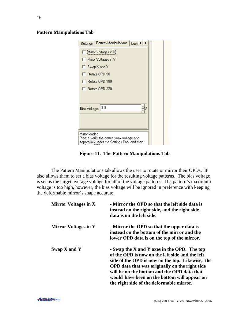
Figure 11. The Pattern Manipulations Tab
The Pattern Manipulations tab allows the user to rotate or mirror their OPDs. It also allows them to set a bias voltage for the resulting voltage patterns. The bias voltage is set as the target average voltage for all of the voltage patterns. If a pattern’s maximum voltage is too high, however, the bias voltage will be ignored in preference with keeping the deformable mirror’s shape accurate. Mirror Voltages in X - Mirror the OPD so that the left side data is instead on the right side, and the right side data is on the left side. Mirror Voltages in Y - Mirror the OPD so that the upper data is instead on the bottom of the mirror and the lower OPD data is on the top of the mirror. Swap X and Y - Swap the X and Y axes in the OPD. The top of the OPD is now on the left side and the left side of the OPD is now on the top. Likewise, the OPD data that was originally on the right side will be on the bottom and the OPD data that would have been on the bottom will appear on the right side of the deformable mirror.
(505) 268-4742 v. 2.0 November 22, 2006

17
Rotate OPD 90 - Rotate the OPD 90 degrees clockwise before calculating the resulting voltage patterns. Rotate OPD 180 - Rotate the OPD 180 degrees clockwise before calculating the resulting voltage patterns. Rotate OPD 270 - Rotate the OPD 270 degrees clockwise before calculating the resulting voltage patterns. Bias Voltage - The target average voltage for each voltage pattern generated by the input OPDs.
(505) 268-4742 v. 2.0 November 22, 2006
18
Custom OPDs 1 Tab
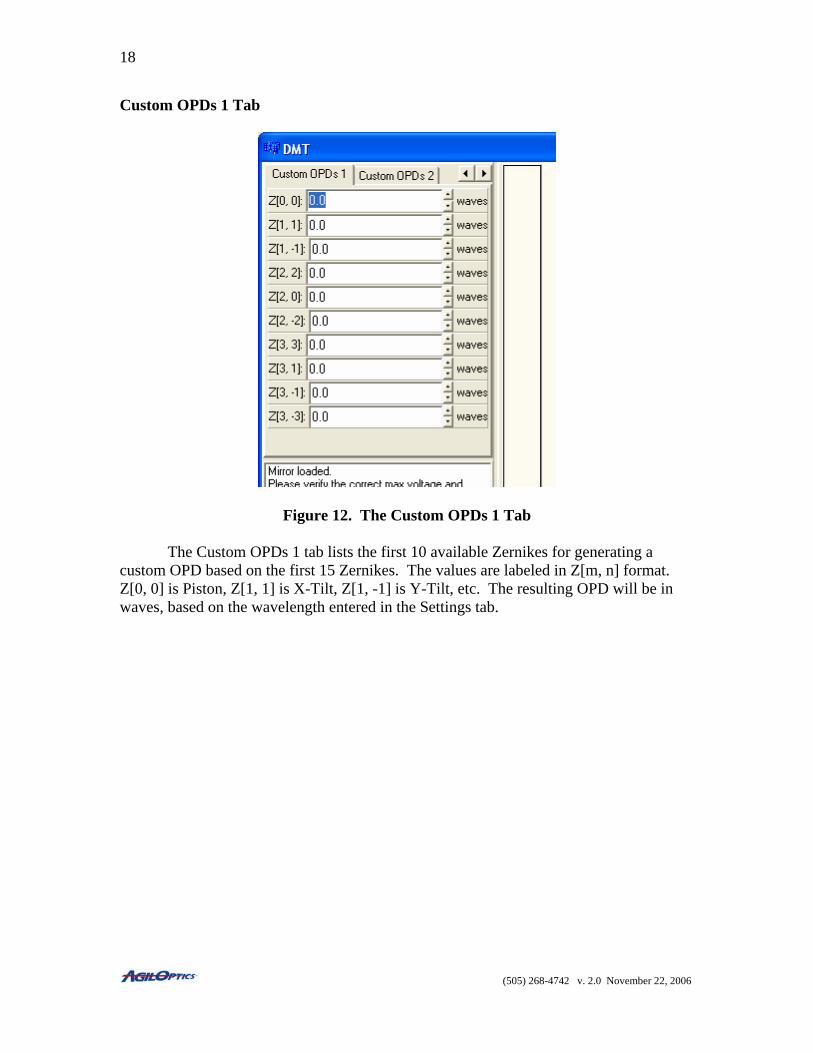
Figure 12. The Custom OPDs 1 Tab
The Custom OPDs 1 tab lists the first 10 available Zernikes for generating a custom OPD based on the first 15 Zernikes. The values are labeled in Z[m, n] format. Z[0, 0] is Piston, Z[1, 1] is X-Tilt, Z[1, -1] is Y-Tilt, etc. The resulting OPD will be in waves, based on the wavelength entered in the Settings tab.
(505) 268-4742 v. 2.0 November 22, 2006
19
Custom OPDs 2 Tab
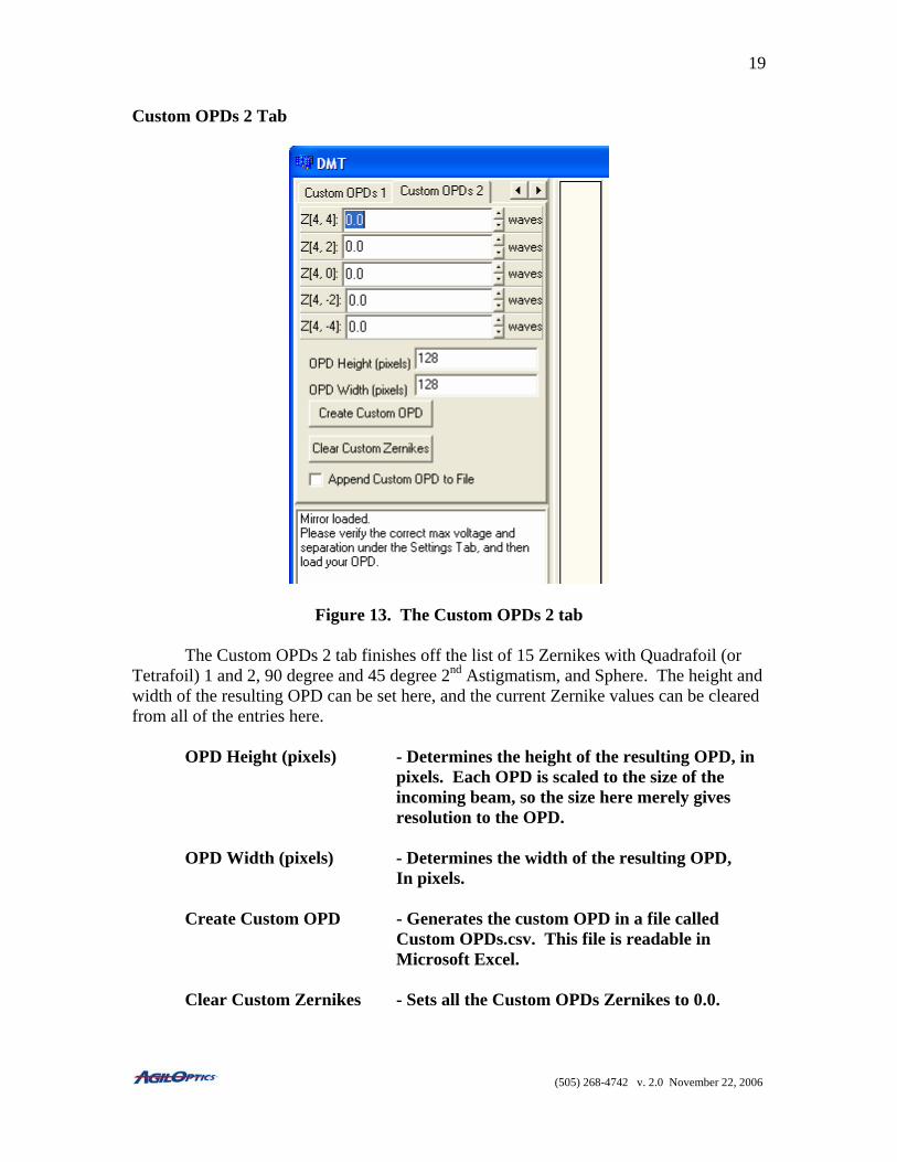
Figure 13. The Custom OPDs 2 tab
The Custom OPDs 2 tab finishes off the list of 15 Zernikes with Quadrafoil (or Tetrafoil) 1 and 2, 90 degree and 45 degree 2nd Astigmatism, and Sphere. The height and width of the resulting OPD can be set here, and the current Zernike values can be cleared from all of the entries here. OPD Height (pixels) - Determines the height of the resulting OPD, in pixels. Each OPD is scaled to the size of the incoming beam, so the size here merely gives resolution to the OPD. OPD Width (pixels) - Determines the width of the resulting OPD, In pixels. Create Custom OPD - Generates the custom OPD in a file called Custom OPDs.csv. This file is readable in Microsoft Excel. Clear Custom Zernikes - Sets all the Custom OPDs Zernikes to 0.0.
(505) 268-4742 v. 2.0 November 22, 2006

20
Append Custom OPD - When set, the next created custom OPD will be to File added to the end of the current Custom OPDs.csv file instead of completely overwriting It. This allows the user to generate multiple Zernike-based OPDs without having to copy the Custom OPDs.csv file to a new name for each one.
(505) 268-4742 v. 2.0 November 22, 2006
21
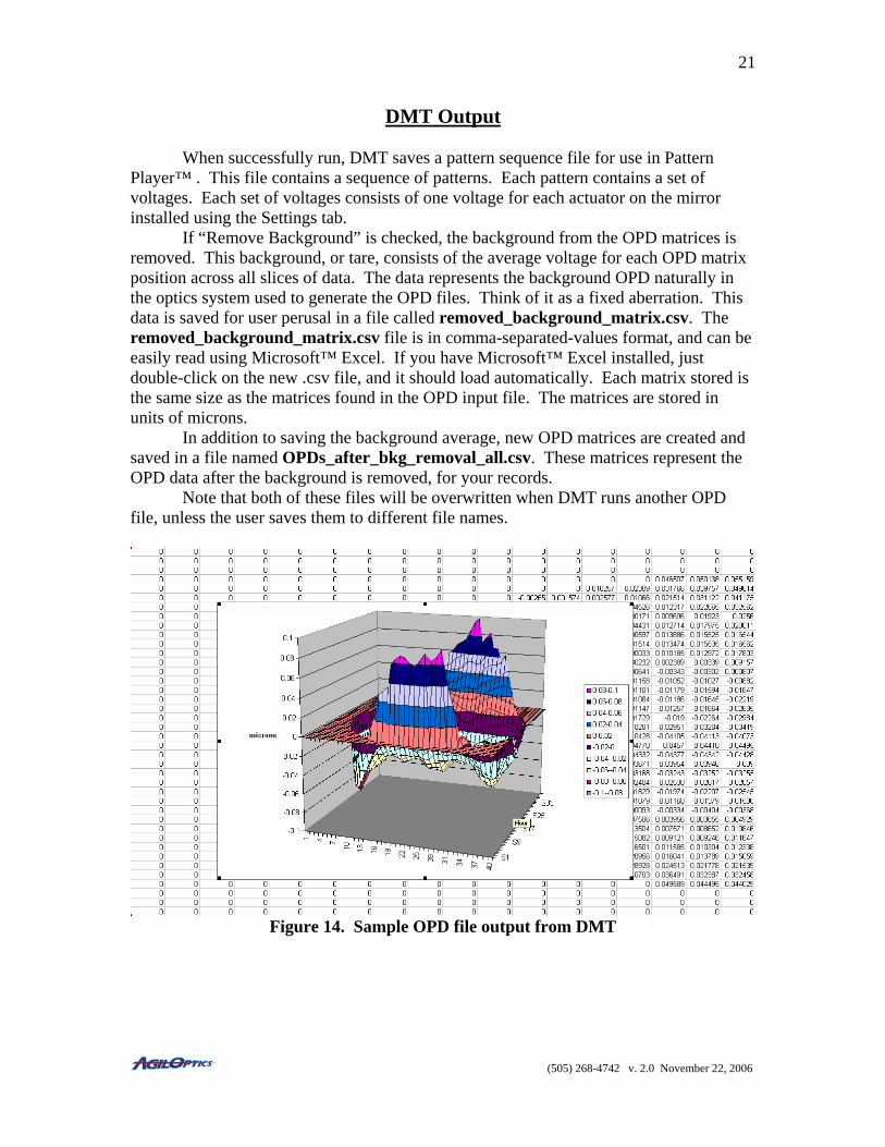
DMT Output When successfully run, DMT saves a pattern sequence file for use in Pattern Player™ . This file contains a sequence of patterns. Each pattern contains a set of voltages. Each set of voltages consists of one voltage for each actuator on the mirror installed using the Settings tab. If “Remove Background” is checked, the background from the OPD matrices is removed. This background, or tare, consists of the average voltage for each OPD matrix position across all slices of data. The data represents the background OPD naturally in the optics system used to generate the OPD files. Think of it as a fixed aberration. This data is saved for user perusal in a file called removed_background_matrix.csv. The removed_background_matrix.csv file is in comma-separated-values format, and can be easily read using Microsoft™ Excel. If you have Microsoft™ Excel installed, just double-click on the new .csv file, and it should load automatically. Each matrix stored is the same size as the matrices found in the OPD input file. The matrices are stored in units of microns.
In addition to saving the background average, new OPD matrices are created and saved in a file named OPDs_after_bkg_removal_all.csv. These matrices represent the OPD data after the background is removed, for your records.
Note that both of these files will be overwritten when DMT runs another OPD file, unless the user saves them to different file names.
Figure 14. Sample OPD file output from DMT
(505) 268-4742 v. 2.0 November 22, 2006
22
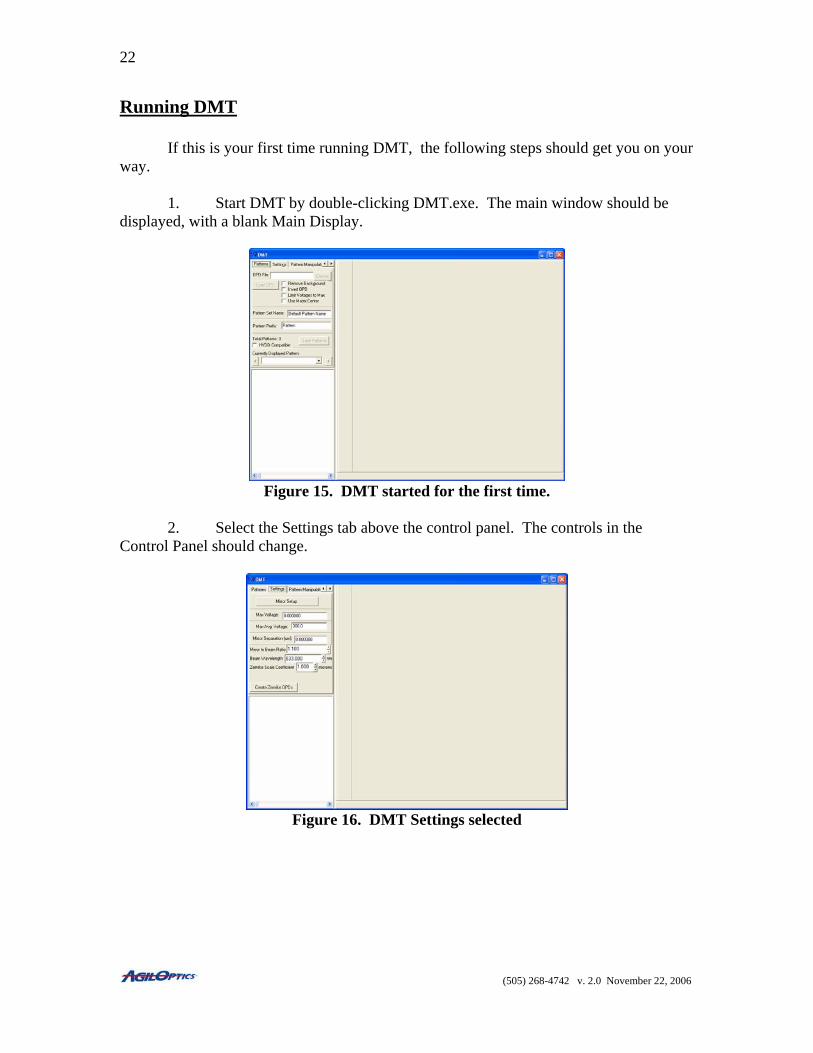
Running DMT If this is your first time running DMT, the following steps should get you on your way. 1. Start DMT by double-clicking DMT.exe. The main window should be displayed, with a blank Main Display.
Figure 15. DMT started for the first time.
2. Select the Settings tab above the control panel. The controls in the Control Panel should change.
Figure 16. DMT Settings selected
(505) 268-4742 v. 2.0 November 22, 2006
23
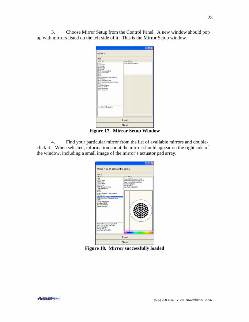
3. Choose Mirror Setup from the Control Panel. A new window should pop up with mirrors listed on the left side of it. This is the Mirror Setup window.
Figure 17. Mirror Setup Window
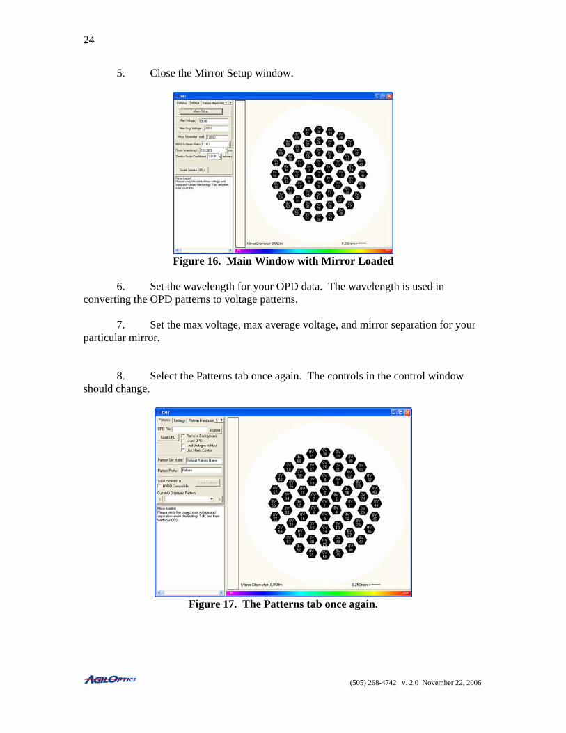
4. Find your particular mirror from the list of available mirrors and double-click it. When selected, information about the mirror should appear on the right side of the window, including a small image of the mirror’s actuator pad array.
Figure 18. Mirror successfully loaded
(505) 268-4742 v. 2.0 November 22, 2006
24
5. Close the Mirror Setup window.
Figure 16. Main Window with Mirror Loaded
6. Set the wavelength for your OPD data. The wavelength is used in converting the OPD patterns to voltage patterns. 7. Set the max voltage, max average voltage, and mirror separation for your particular mirror.
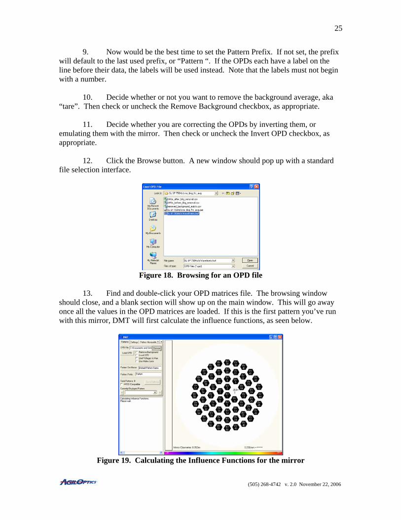
8. Select the Patterns tab once again. The controls in the control window should change.
Figure 17. The Patterns tab once again.
(505) 268-4742 v. 2.0 November 22, 2006
25
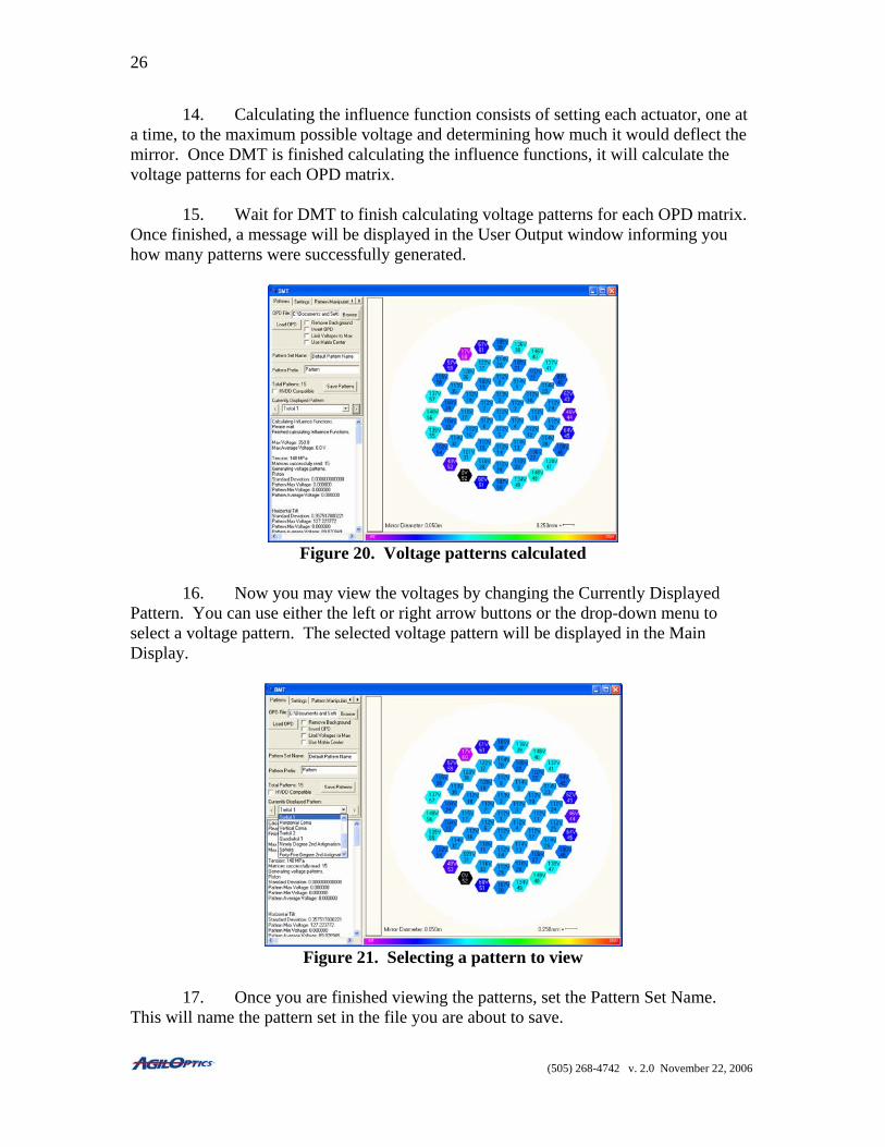
9. Now would be the best time to set the Pattern Prefix. If not set, the prefix will default to the last used prefix, or “Pattern “. If the OPDs each have a label on the line before their data, the labels will be used instead. Note that the labels must not begin with a number. 10. Decide whether or not you want to remove the background average, aka “tare”. Then check or uncheck the Remove Background checkbox, as appropriate. 11. Decide whether you are correcting the OPDs by inverting them, or emulating them with the mirror. Then check or uncheck the Invert OPD checkbox, as appropriate. 12. Click the Browse button. A new window should pop up with a standard file selection interface.
Figure 18. Browsing for an OPD file
13. Find and double-click your OPD matrices file. The browsing window should close, and a blank section will show up on the main window. This will go away once all the values in the OPD matrices are loaded. If this is the first pattern you’ve run with this mirror, DMT will first calculate the influence functions, as seen below.
Figure 19. Calculating the Influence Functions for the mirror
(505) 268-4742 v. 2.0 November 22, 2006
26
14. Calculating the influence function consists of setting each actuator, one at a time, to the maximum possible voltage and determining how much it would deflect the mirror. Once DMT is finished calculating the influence functions, it will calculate the voltage patterns for each OPD matrix.
15. Wait for DMT to finish calculating voltage patterns for each OPD matrix. Once finished, a message will be displayed in the User Output window informing you how many patterns were successfully generated.
Figure 20. Voltage patterns calculated
16. Now you may view the voltages by changing the Currently Displayed
Pattern. You can use either the left or right arrow buttons or the drop-down menu to select a voltage pattern. The selected voltage pattern will be displayed in the Main Display.
Figure 21. Selecting a pattern to view
17. Once you are finished viewing the patterns, set the Pattern Set Name.
This will name the pattern set in the file you are about to save.
(505) 268-4742 v. 2.0 November 22, 2006
27
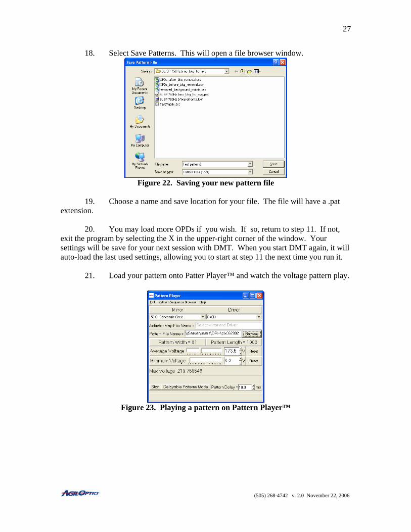
18. Select Save Patterns. This will open a file browser window.
Figure 22. Saving your new pattern file
19. Choose a name and save location for your file. The file will have a .pat
extension. 20. You may load more OPDs if you wish. If so, return to step 11. If not,
exit the program by selecting the X in the upper-right corner of the window. Your settings will be save for your next session with DMT. When you start DMT again, it will auto-load the last used settings, allowing you to start at step 11 the next time you run it. 21. Load your pattern onto Patter Player™ and watch the voltage pattern play.
Figure 23. Playing a pattern on Pattern Player™
(505) 268-4742 v. 2.0 November 22, 2006
28
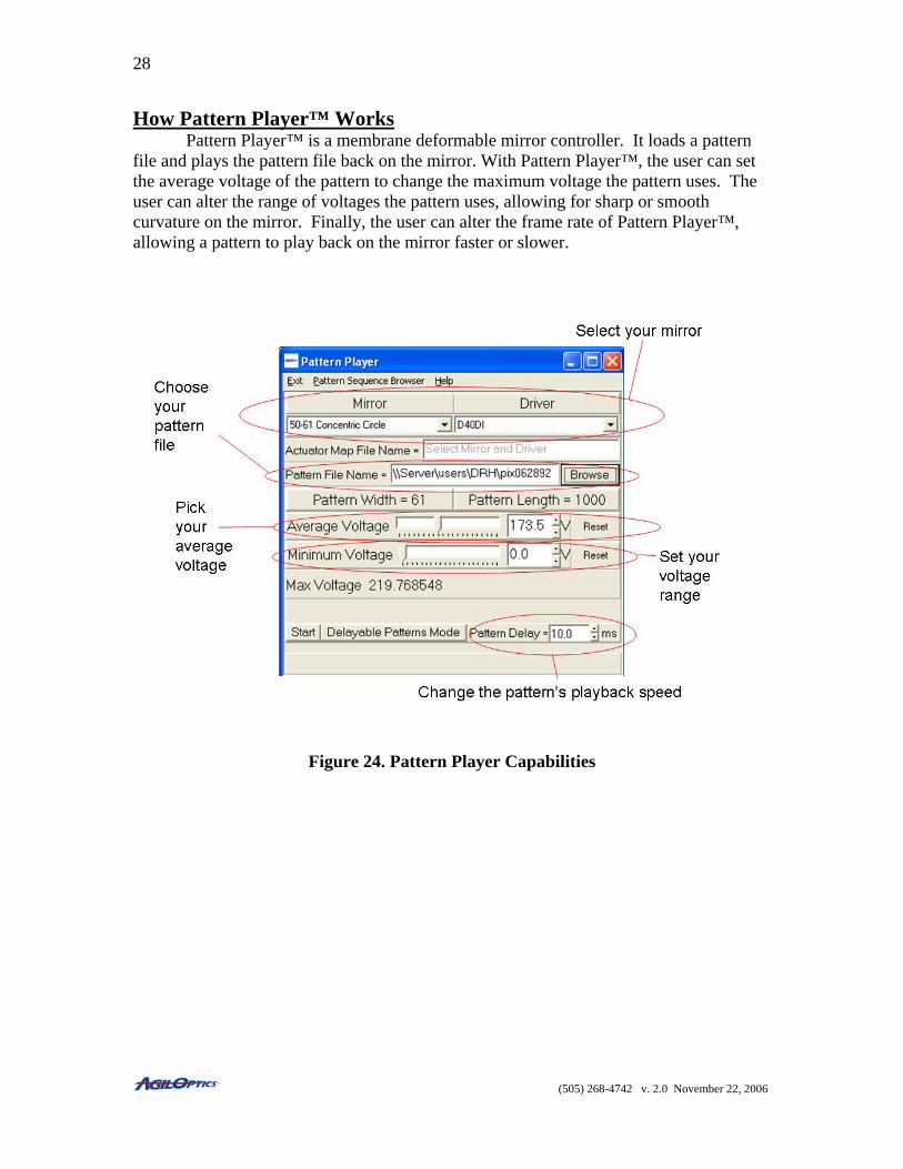
How Pattern Player™ Works Pattern Player™ is a membrane deformable mirror controller. It loads a pattern file and plays the pattern file back on the mirror. With Pattern Player™, the user can set the average voltage of the pattern to change the maximum voltage the pattern uses. The user can alter the range of voltages the pattern uses, allowing for sharp or smooth curvature on the mirror. Finally, the user can alter the frame rate of Pattern Player™, allowing a pattern to play back on the mirror faster or slower.
Figure 24. Pattern Player Capabilities
(505) 268-4742 v. 2.0 November 22, 2006
29
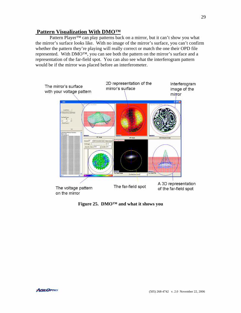
Pattern Visualization With DMO™ Pattern Player™ can play patterns back on a mirror, but it can’t show you what the mirror’s surface looks like. With no image of the mirror’s surface, you can’t confirm whether the pattern they’re playing will really correct or match the one their OPD file represented. With DMO™, you can see both the pattern on the mirror’s surface and a representation of the far-field spot. You can also see what the interferogram pattern would be if the mirror was placed before an interferometer.
Figure 25. DMO™ and what it shows you
(505) 268-4742 v. 2.0 November 22, 2006
30
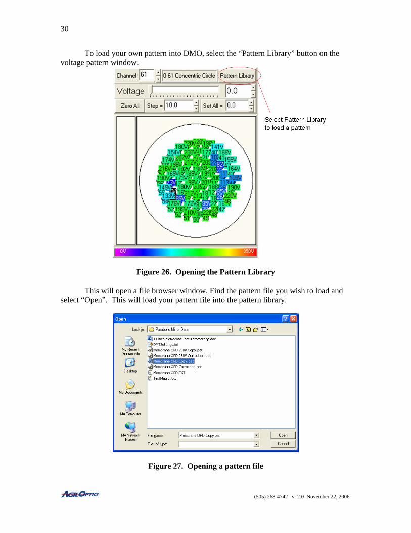
To load your own pattern into DMO, select the “Pattern Library” button on the voltage pattern window.
Figure 26. Opening the Pattern Library
This will open a file browser window. Find the pattern file you wish to load and select “Open”. This will load your pattern file into the pattern library.
Figure 27. Opening a pattern file
(505) 268-4742 v. 2.0 November 22, 2006
31
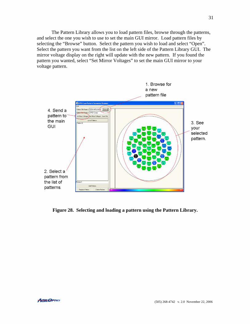
The Pattern Library allows you to load pattern files, browse through the patterns, and select the one you wish to use to set the main GUI mirror. Load pattern files by selecting the “Browse” button. Select the pattern you wish to load and select “Open”. Select the pattern you want from the list on the left side of the Pattern Library GUI. The mirror voltage display on the right will update with the new pattern. If you found the pattern you wanted, select “Set Mirror Voltages” to set the main GUI mirror to your voltage pattern.
Figure 28. Selecting and loading a pattern using the Pattern Library.
(505) 268-4742 v. 2.0 November 22, 2006