Embed Size (px)
Citation preview

As we are constantly endeavouring to improve the performance of our equipment.
The company reserves the right to make alteration from time to time and equipment differ from that detailed in this brochure.
[PRODUCTCATALOG
2009]
3616-3618
201812
(021) 59138888
(021) 59136782
800 800-820-5009
Address:3616-3618 Cao'an Road, Jiangqiao Shanghai
P.C.: 201812
Switchboard: (021) 59138888
Fax: (021) 59136782
800 Free consultation Tel:800-820-5009
All rights reserved.Pirate is forbidden.
2009 The first printing of the 2009 edition
20th.Oct.2009Date of printing
Inosculating innovative technologies, interpreting the art of fluid!
www.lcpumps.com
DLZ SERIES LOW-NOSIE VERTICAL MULTI-STAGE CENTRIFUGAL PUMP

4 JB/TQ809-89
GB5657-1995
5
1 DLZ
DLZ
80
80
2
3
1. Model DLZ low-noise vertical multi-stage centrifugal
pump is a new-style product of environmental protection and
features one combined unit formed by pump and motor, the
motor is a low-noise water-cooled one and use of water cooling
instead of a blower can lower noise and energy consumption.
The water for cooling the motor can be either the one the pump
transports or the one externally supplied.
Model DLZ pump is used for transporting pure water and
various liquids with both phystcal and chemical natures similar
to the pure water, the transported medium's temperature is
below 80 ; for the said temperature above 80 , use external
supplied cooling water to cool the motor. Suitable for industrial
and city water supply, high building boosted water supply, air-
conditioning, warming, fire-fighting, circular boost and so on.
2. The pump is vertically mounted, featuring compact
structure, low noise, less area of land etc.
3. Model meaning:
CONTENTS
1
1-4
( ) 4
4-6
DLZ 7
8-29
30
31
32
General
Description of structure
Selectable materials and structural characteristics(part of pump)
Assembly, disassembly and repair
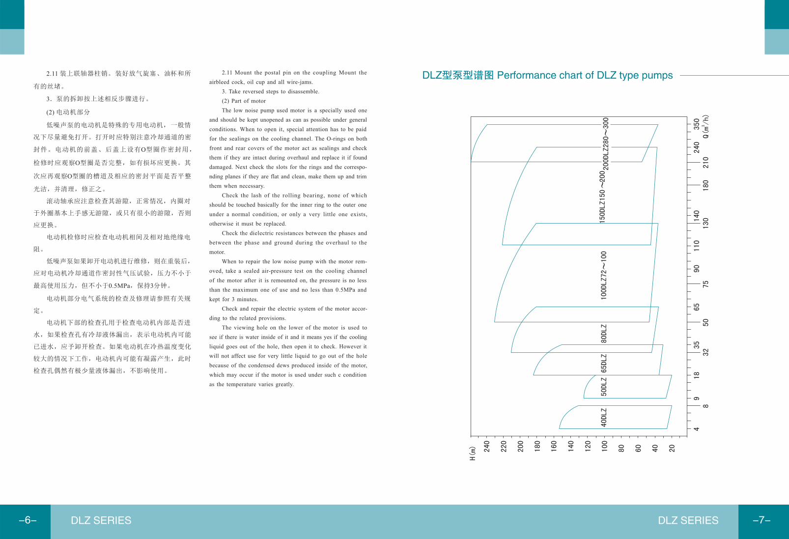
Performance chart of DLZ type pumps
Performance curve chart & table, installation drawing & table
Several ways of installation
Fittings drawing and dimension table
Basic drawing and link dimension
65 DL Z 30 - 16 5
Low-noise vertical multi-stage pump consists of pump
and motor, the motor is a special water-cooled low-noise motor.
The overall configuration is such as the motor is on the upper
and the pump on the lower, an elastic clutch is jointed between
both motor and pump.
5
16m
30m /h
65mm
5 impellers
The head is 16m produced per impeller
The quantity of low of the pump is 30m /h
Low noise
Vertical multi-stage pump
Inlet aperture of the pump is 65mm
3 3
4. The technical standards executed for the series pump:
JB/TQ809-89 Model and basic parameters of vertical multi-
stage pump ,GB5657-1995 Technical conditions of centrif-
ugal pump, category .
5. Rotary direction of pump: CCW viewing downward
from the motor.

2 DLZ
2.1
2.2
2.3
2.4
3/8
(1) ( 1)
1 DLZ
0 90 180
270 ( )
( 180 )
(1) Part of pump(See Figure 1)
1. Model DLZ pump has a vertical structure, with the
suction on the inlet section on the lower of it and the drain
on the outlet section on the upper of it, both are horizontally
arranged. The stage number can be increased or decreased per
the need of the head at use and the included angle between
both inlet and outlet can be selected in 0 , 90 , 180 and
270 four orientations(see the Figure below) per different uses
and installations to adjust the mounting position of the drain
(the said angle is set in 180 when ex-works unless otherwise
specified).
2. Major parts of the pump: inlet, middle and outlet se-
ctions, filling body, impeller, guide vane, guide vane on outlet
section, shaft bearing, shaft sleeve, balance drum and sleeve,
link stand etc.
2.1 The inlet, middle and outlet sections and the guide
vane are made of cast-iron and mutually form the working part
of liquid transportation of the pump.
2.2 The shaft is made of qualified carbon steel and on it
the upper muff, impeller, balance drum, muffs etc. are mounted,
they are fixed on the shaft with keys and the muff nuts to from
the rotor of the pump.
2.3 The axial force on the impeller is mainly balanced by
the balance drum and the residual axial force is borne by the
bearing on the upper of the shaft.
2.4 The shaft seal can not only use soft packing but also
be changed with mechanical seal, when using soft packing, the
shaft sleeve can be replaced when worn out and, when as the
mechanical seal, the pressure water inside of the balance room
is used for lubrication and cooling.
When as the filling seal, the 3/8 flexible union on the
outlet section is used through the flexible pipe to drain the
water leaked from the filling body to the underground ditch
to keep the place around the pump clean.
1
2
3
4
5
6
7
8
9
10
11
12
13
14
15
16
17
18
19
20
21
22
23
24
Inlet section
Seal ring/seal pad
Middle section
Impeller
Balance drum
Outlet section
Shaft
Mechanical seal/body
Shaft sleeve
Water retaining sleeve
Bearing body
Bearing
Bearing cover
Linkage stand
Coupling
Mechanical seal/seal gland
Back water pipe part
Last-stage guide vane
Guide vane
Water lubricated bearing sleeve
Water lubricated bearing
Water lubricated bearing
Drainage wire-jam
Water lubricated bearing cover

1
Shaft seal form
2.5
(2)
2
O
Y
(1)
1
1.1
1.2
1.3
1.4
1.5
2
2.1
2.2
2.3
2.4
2.5
2.6
2.7
2.8
2.9
2.10
(1) Part of pump
1. Assembly of parts:
1.1 Insert the sand-proof tube into the hole on the inlet
section. Put the water bearing into the water bearing body
and then in the inlet section.
1.2 Mount the upstage vane on the outlet section, and
put in the middle suction.
1.3 Mount the back water pipe.
1.4 Inlay the short key on the shaft and put the lower
shaft sleeve on, then fix it with the retaining ring and nuts.
1.5 Mount the coupling on the motor.
2. Assembly:
2.1 Insert the shaft into the inlet section and put the key
into the key slot on the shaft and mount the first-stage impeller
on along with the shaft.
2.2 Mount the middle section already mounted with the
guide vane on the outlet section along with the shaft, then the
second stage key and impeller, repeat these steps till all keys,
impellers and middle sections mounted.
2.3 Mount the outlet section on the middle one, then the
balance drum.
2.4 Mount the seal body on the outlet section along with
the shaft and, with the tensile bolt, tighten the inlet, middle
and outlet sections and the seal body together.
2.5 The shaft seal, in case of a mechanical seal, should
be first mounted on the sleeve and then on the shaft and, after
the pump is mounted, is fixed with the gland.
2.6 Put the water retaining sleeve in. Mount the bearing
case on the filling body and tighten it with a bolt.
2.7 Have already pack the bearning suit of the good be-
aring arrived the stalk topornd fix with nuts and fix with nuts.
2.8 Add a proper amount of grease into the bearing case,
put a paper pad on the bearing cover, then mount the bearing
cover on the case and fix it with a bolt. Then mount the pump
coupling and turn the rotor with hand to check if it turns
flexibly.
2.9 Mount the linkage stand on the seal body and fix it
with nuts then nount the motor on the stand.
2.10 Mount the back water pipe on the pump.
2.5 The bearing on the upper end of the pump uses mol-
ybdenum disulfide grease for lubrication.
(2) Part of motor
The motor is a specially designed water cooled low noise
one, see Figure 2 for its structure.
Its structural principle comes like this: set up a cooling
channel on the periphery of the motor and, via the inlet pipe-
line, lead the water transported by the pump in the channel
from the high pressure part of the pump and ,after it cools the
motor, the cooling water goes back to the low-pressure part of
the pump via the back water pipelines to from a circulation,
not only cooling the motor but also being no loss of water,
thus keeping the site dry and the pump efficiency.
The casing of the motor covers casing, front and rear
covers and between the casing and both front and rear covers
there are O -rings as the sealings to prevent water leakage
and from getting in the motor, which is a very important part
of a low noise motor.
The bearings, as sealed ones, are mounted on both front
and rear covers, inside of them are filled with lubricant so as
not necessary to lubricate within the effective working period.
Both motor and stator of the motor are basically same as
those of the ordinary Y-type motors.
Packing seal
Mechanical seal
2
Bearing
Domestic qualified bearing
Imported low noise bearing
3
Impeller
HT200
Cast-iron HT200
ZCuSn10Zn2
ZCuSn10Zn2 copper alloy
4
Shaft
45#
45#Steel
Stainless steel
2.11
3
(2)
O
O
O
0.5MPa 3
2.11 Mount the postal pin on the coupling Mount the
airbleed cock, oil cup and all wire-jams.
3. Take reversed steps to disassemble.
(2) Part of motor
The low noise pump used motor is a specially used one
and should be kept unopened as can as possible under general
conditions. When to open it, special attention has to be paid
for the sealings on the cooling channel. The O-rings on both
front and rear covers of the motor act as sealings and check
them if they are intact during overhaul and replace it if found
damaged. Next check the slots for the rings and the correspo-
nding planes if they are flat and clean, make them up and trim
them when necessary.
Check the lash of the rolling bearing, none of which
should be touched basically for the inner ring to the outer one
under a normal condition, or only a very little one exists,
otherwise it must be replaced.
Check the dielectric resistances between the phases and
between the phase and ground during the overhaul to the
motor.
When to repair the low noise pump with the motor rem-
oved, take a sealed air-pressure test on the cooling channel
of the motor after it is remounted on, the pressure is no less
than the maximum one of use and no less than 0.5MPa and
kept for 3 minutes.
Check and repair the electric system of the motor accor-
ding to the related provisions.
The viewing hole on the lower of the motor is used to
see if there is water inside of it and it means yes if the cooling
liquid goes out of the hole, then open it to check. However it
will not affect use for very little liquid to go out of the hole
because of the condensed dews produced inside of the motor,
which may occur if the motor is used under such c condition
as the temperature varies greatly.

Pump modelPump model SeriesSeries
Series
CapacityCapacityHead(m)
Head(m)
Power(kw)
Power(kw)
Speed(r/min)
Speed(r/min) (NPSH)r(NPSH)r
Weight(kg)
Weight(kg) (m /h)
3(m /h)
3(L/s)(L/s)
40DLZ6-1240DLZ6-12
4.26
7.2
4.26
7.2
4.26
7.2
4.26
7.2
4.26
7.2
4.26
7.2
4.2
6
7.2
4.2
6
7.2
4.2
6
7.2
4.2
6
7.2
4.2
6
7.2
9182.677
10494.488
11710699
130118110
143130121
156142132
26
23.6
22
39
35.4
33
52
47.2
44
65
59
55
78
70.8
66
2
3
4
5
6
7
8
9
10
11
12
1.17
1.67
2
1.17
1.67
2
1.17
1.67
2
1.17
1.67
2
1.17
1.67
2
1.171.67
2
1.171.67
2
1.171.67
2
1.171.67
2
1.171.67
2
1.171.67
2
1.5
2.2
3
4
4
5.5
5.5
7.5
7.5
7.5
11
1480
1480
1480
1480
1480
1480
1480
1480
1480
1480
1480
3
3.2
3.6
3
3.2
3.6
3
3.2
3.6
3
3.2
3.6
3
3.2
3.6
33.23.6
33.23.6
33.23.6
33.23.6
33.23.6
33.23.6
230
280
300
330
350
400
415
450
470
490
560
Pump model
40DLZ6-12
Figure dimension Installation dimension Inlet flange Outlet flange
H a a H1 H2 h B b b 4- d D0 D01 D02 n-d0 D1 D11 D12 n-d1
2
3
4
5
6
7
8
9
10
11
12
926
1031
1091
1168
1228
1371
1431
1491
1551
1611
1782
345 345
345 345
345 345
345 345
345 345
345 345
345 345
345 345
345 345
345 345
345 345
112
112
112
112
112
112
112
112
112
112
112
282
342
402
462
522
582
642
702
762
822
882
55
55
55
55
55
55
55
55
55
55
55
225
225
225
225
225
225
225
225
225
225
225
300 300
300 300
300 300
300 300
300 300
300 300
300 300
300 300
300 300
300 300
300 300
18
18
18
18
18
18
18
18
18
18
18
40
40
40
40
40
40
40
40
40
40
40
110
110
110
110
110
110
110
110
110
110
110
150
150
150
150
150
150
150
150
150
150
150
4- 17.5
4- 17.5
4- 17.5
4- 17.5
4- 17.5
4- 17.5
4- 17.5
4- 17.5
4- 17.5
4- 17.5
4- 17.5
40
40
40
40
40
40
40
40
40
40
40
110
110
110
110
110
110
110
110
110
110
110
150
150
150
150
150
150
150
150
150
150
150
4- 17.5
4- 17.5
4- 17.5
4- 17.5
4- 17.5
4- 17.5
4- 17.5
4- 17.5
4- 17.5
4- 17.5
4- 17.5

Pump modelPump model SeriesSeries
Series
CapacityCapacityHead(m)
Head(m)
Power(kw)
Power(kw)
Speed(r/min)
Speed(r/min) (NPSH)r(NPSH)r
Weight(kg)
Weight(kg) (m /h)
3(m /h)
3(L/s)(L/s)
50DLZ12-12.5 50DLZ12-12.5
9
12.6
18
9
12.6
18
9
12.6
18
9
12.6
18
9
12.6
18
9
12.6
18
9
12.6
18
9
12.6
18
9
12.6
18
94.5
85.4
77
108
97.6
88
121.5
110
99
135
122
110
27
24.4
22
40.5
36.6
33
54
48.8
44
67.5
61
55
81
73.2
66
2
3
4
5
6
7
8
9
10
2.5
3.5
5
2.5
3.5
5
2.5
3.5
5
2.5
3.5
5
2.5
3.5
5
2.5
3.5
5
2.5
3.5
5
2.5
3.5
5
2.5
3.5
5
3
3
4
5.5
5.5
7.5
7.5
11
11
1480
1480
1480
1480
1480
1480
1480
1480
1480
2.6
2.7
3.2
2.6
2.7
3.2
2.6
2.7
3.2
2.6
2.7
3.2
2.6
2.7
3.2
2.6
2.7
3.2
2.6
2.7
3.2
2.6
2.7
3.2
2.6
2.7
3.2
235
255
285
330
350
380
405
470
490
Pump modelFigure dimension Installation dimension Inlet flange Outlet flange
H a a H1 H2 h B b b 4- d D0 D01 D02 n-d0 D1 D11 D12 n-d1
2
3
4
5
6
7
8
9
10
1073
1141
1226
1377
1445
1513
1581
1765
1833
345 345
345 345
345 345
345 345
345 345
345 345
345 345
345 345
345 345
105
105
105
105
105
105
105
105
105
293
361
429
497
565
633
701
769
837
58
58
58
58
58
58
58
58
58
220
220
220
220
220
220
220
220
220
305 305
305 305
305 305
305 305
305 305
305 305
305 305
305 305
305 305
18
18
18
18
18
18
18
18
18
50
50
50
50
50
50
50
50
50
125
125
125
125
125
125
125
125
125
165
165
165
165
165
165
165
165
165
4- 17.5
4- 17.5
4- 17.5
4- 17.5
4- 17.5
4- 17.5
4- 17.5
4- 17.5
4- 17.5
40
40
40
40
40
40
40
40
40
110
110
110
110
110
110
110
110
110
150
150
150
150
150
150
150
150
150
4- 17.5
4- 17.5
4- 17.5
4- 17.5
4- 17.5
4- 17.5
4- 17.5
4- 17.5
4- 17.5
50DLZ12-12.5
Pump modelPump model SeriesSeries
Series
CapacityCapacityHead(m)
Head(m)
Power(kw)
Power(kw)
Speed(r/min)
Speed(r/min) (NPSH)r(NPSH)r
Weight(kg)
Weight(kg) (m /h)
3(m /h)
3(L/s)(L/s)
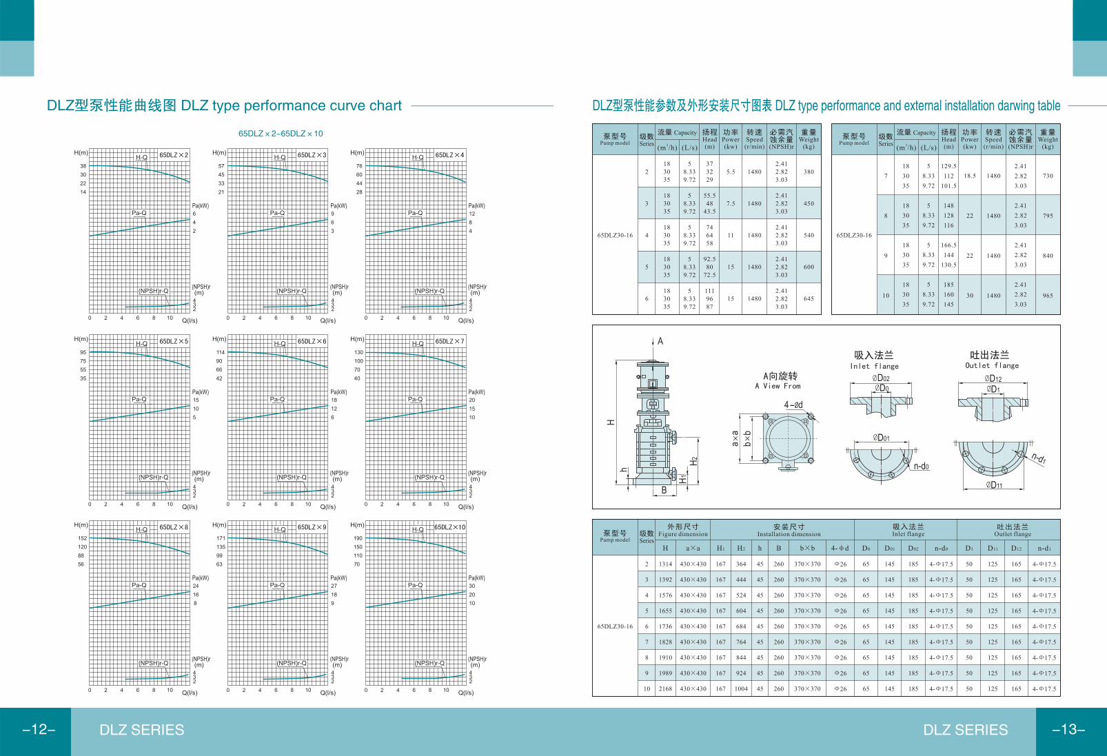
65DLZ30-16 65DLZ30-16
18
30
35
18
30
35
18
30
35
18
30
35
18
30
35
18
30
35
18
30
35
18
30
35
18
30
35
129.5
112
101.5
148
128
116
166.5
144
130.5
185
160
145
37
32
29
55.5
48
43.5
74
64
58
92.5
80
72.5
111
96
87
2
3
4
5
6
7
8
9
10
5
8.33
9.72
5
8.33
9.72
5
8.33
9.72
5
8.33
9.72
5
8.33
9.72
5
8.33
9.72
5
8.33
9.72
5
8.33
9.72
5
8.33
9.72
5.5
7.5
11
15
15
18.5
22
22
30
1480
1480
1480
1480
1480
1480
1480
1480
1480
2.41
2.82
3.03
2.41
2.82
3.03
2.41
2.82
3.03
2.41
2.82
3.03
2.41
2.82
3.03
2.41
2.82
3.03
2.41
2.82
3.03
2.41
2.82
3.03
2.41
2.82
3.03
380
450
540
600
645
730
795
840
965
Pump modelFigure dimension Installation dimension Inlet flange Outlet flange
H a a H1 H2 h B b b 4- d D0 D01 D02 n-d0 D1 D11 D12 n-d1
2
3
4
5
6
7
8
9
10
1314
1392
1576
1655
1736
1828
1910
1989
2168
430 430
430 430
430 430
430 430
430 430
430 430
430 430
430 430
430 430
167
167
167
167
167
167
167
167
167
364
444
524
604
684
764
844
924
1004
45
45
45
45
45
45
45
45
45
260
260
260
260
260
260
260
260
260
370 370
370 370
370 370
370 370
370 370
370 370
370 370
370 370
370 370
26
26
26
26
26
26
26
26
26
65
65
65
65
65
65
65
65
65
145
145
145
145
145
145
145
145
145
185
185
185
185
185
185
185
185
185
4- 17.5
4- 17.5
4- 17.5
4- 17.5
4- 17.5
4- 17.5
4- 17.5
4- 17.5
4- 17.5
50
50
50
50
50
50
50
50
50
125
125
125
125
125
125
125
125
125
165
165
165
165
165
165
165
165
165
4- 17.5
4- 17.5
4- 17.5
4- 17.5
4- 17.5
4- 17.5
4- 17.5
4- 17.5
4- 17.5
65DLZ30-16

Pump modelPump model SeriesSeries
Series
CapacityCapacityHead(m)
Head(m)
Power(kw)
Power(kw)
Speed(r/min)
Speed(r/min) (NPSH)r(NPSH)r
Weight(kg)
Weight(kg) (m /h)
3(m /h)
3(L/s)(L/s)
80DLZ50-20 80DLZ50-20
32.4
50.4
65
32.4
50.4
65
32.4
50.4
65
32.4
50.4
65
32.4
50.4
65
32.4
50.4
65
32.4
50.4
65
32.4
50.4
65
32.4
50.4
65
151
140
120
173
160
137
194
180
154
216
200
171
42
40
36
63
60
54
84
80
72
105
100
90
126
120
108
2
3
4
5
6
7
8
9
10
9
14
18
9
14
18
9
14
18
9
14
18
9
14
18
9
14
18
9
14
18
9
14
18
9
14
18
11
15
22
30
30
37
45
45
55
1480
1480
1480
1480
1480
1480
1480
1480
1480
2.2
2.5
2.8
2.2
2.5
2.8
2.2
2.5
2.8
2.2
2.5
2.8
2.2
2.5
2.8
2.2
2.5
2.8
2.2
2.5
2.8
2.2
2.5
2.8
2.2
2.5
2.8
570
640
760
900
945
1040
1120
1175
1335
Pump modelFigure dimension Installation dimension Inlet flange Outlet flange
H a a H1 H2 h B b b 4- d D0 D01 D02 n-d0 D1 D11 D12 n-d1
2
3
4
5
6
7
8
9
10
1478
1567
1641
1830
1919
2051
2115
2232
2379
470 470
470 470
470 470
470 470
470 470
470 470
470 470
470 470
470 470
150
150
150
150
150
150
150
150
150
427
516
605
694
783
872
961
1050
1139
55
55
55
55
55
55
55
55
55
280
280
280
280
280
280
280
280
280
410 410
410 410
410 410
410 410
410 410
410 410
410 410
410 410
410 410
26
26
26
26
26
26
26
26
26
80
80
80
80
80
80
80
80
80
160
160
160
160
160
160
160
160
160
200
200
200
200
200
200
200
200
200
8- 17.5
8- 17.5
8- 17.5
8- 17.5
8- 17.5
8- 17.5
8- 17.5
8- 17.5
8- 17.5
65
65
65
65
65
65
65
65
65
145
145
145
145
145
145
145
145
145
185
185
185
185
185
185
185
185
185
80DLZ50-20
8- 17.5
8- 17.5
8- 17.5
8- 17.5
8- 17.5
8- 17.5
8- 17.5
8- 17.5
8- 17.5

Pump modelPump model SeriesSeries
Series
CapacityCapacityHead(m)
Head(m)
Power(kw)
Power(kw)
Speed(r/min)
Speed(r/min) (NPSH)r(NPSH)r
Weight(kg)
Weight(kg) (m /h)
3(m /h)
3(L/s)(L/s)
100DLZ72-20 100DLZ72-20
50.4
72
86.4
50.4
72
86.4
50.4
72
86.4
50.4
72
86.4
50.4
72
86.4
50.4
72
86.4
50.4
72
86.4
50.4
72
86.4
50.4
72
86.4
157
140
126
184
160
144
207
180
162
230
200
180
46
40
36
69
60
54
92
80
72
115
100
90
138
120
108
2
3
4
5
6
7
8
9
10
14
20
24
14
20
24
14
20
24
14
20
24
14
20
24
14
20
24
14
20
24
14
20
24
14
20
24
15
18.5
30
37
37
45
55
55
75
1480
1480
1480
1480
1480
1480
1480
1480
1480
2.5
2.8
3.1
2.5
2.8
3.1
2.5
2.8
3.1
2.5
2.8
3.1
2.5
2.8
3.1
2.5
2.8
3.1
2.5
2.8
3.1
2.5
2.8
3.1
2.5
2.8
3.1
755
890
985
1070
1235
1435
1490
1590
1650
Pump modelFigure dimension Installation dimension Inlet flange Outlet flange
H a a H1 H2 h B b b 4- d D0 D01 D02 n-d0 D1 D11 D12 n-d1
2
3
4
5
6
7
8
9
10
1476
1539
1817
1963
2081
2194
2378
2531
2679
465 465
465 465
465 465
465 465
465 465
465 465
465 465
465 465
465 465
172
172
172
172
172
172
172
172
172
467
570
673
776
879
982
1085
1188
1291
50
50
50
50
50
50
50
50
50
280
280
280
280
280
280
280
280
280
410 410
410 410
410 410
410 410
410 410
410 410
410 410
410 410
410 410
24
24
24
24
24
24
24
24
24
100
100
100
100
100
100
100
100
100
180
180
180
180
180
180
180
180
180
220
220
220
220
220
220
220
220
220
8- 17.5
8- 17.5
8- 17.5
8- 17.5
8- 17.5
8- 17.5
8- 17.5
8- 17.5
8- 17.5
80
80
80
80
80
80
80
80
80
160
160
160
160
160
160
160
160
160
200
200
200
200
200
200
200
200
200
8- 17.5
8- 17.5
8- 17.5
8- 17.5
8- 17.5
8- 17.5
8- 17.5
8- 17.5
8- 17.5
100DLZ70-20
Pump modelPump model SeriesSeries
Series
CapacityCapacityHead(m)
Head(m)
Power(kw)
Power(kw)
Speed(r/min)
Speed(r/min) (NPSH)r(NPSH)r
Weight(kg)
Weight(kg) (m /h)
3(m /h)
3(L/s)(L/s)
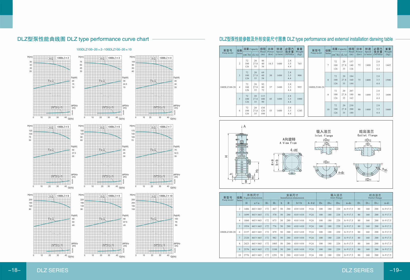
100DLZ100-20 100DLZ100-20
72
100
126
72
100
126
72
100
126
72
100
126
72
100
126
72
100
126
72
100
126
72
100
126
72
100
126
157
140
126
184
160
144
207
180
162
230
200
180
46
40
36
69
60
54
92
80
72
115
100
90
138
120
108
2
3
4
5
6
7
8
9
10
20
27.8
35
20
27.8
35
20
27.8
35
20
27.8
35
20
27.8
35
20
27.8
35
20
27.8
35
20
27.8
35
20
27.8
35
18.5
30
37
45
55
75
75
90
90
1480
1480
1480
1480
1480
1480
1480
1480
1480
2.8
3.5
4.4
2.8
3.5
4.4
2.8
3.5
4.4
2.8
3.5
4.4
2.8
3.5
4.4
2.8
3.5
4.4
2.8
3.5
4.4
2.8
3.5
4.4
2.8
3.5
4.4
765
900
995
1080
1245
1445
1500
1600
1660
Pump modelFigure dimension Installation dimension Inlet flange Outlet flange
H a a H1 H2 h B b b 4- d D0 D01 D02 n-d0 D1 D11 D12 n-d1
2
3
4
5
6
7
8
9
10
1486
1699
1860
1954
2157
2320
2423
2576
2776
465 465
465 465
465 465
465 465
465 465
465 465
465 465
465 465
465 465
172
172
172
172
172
172
172
172
172
467
570
673
776
879
982
1085
1188
1291
50
50
50
50
50
50
50
50
50
280
280
280
280
280
280
280
280
280
410 410
410 410
410 410
410 410
410 410
410 410
410 410
410 410
410 410
24
24
24
24
24
24
24
24
24
100
100
100
100
100
100
100
100
100
180
180
180
180
180
180
180
180
180
220
220
220
220
220
220
220
220
220
8- 17.5
8- 17.5
8- 17.5
8- 17.5
8- 17.5
8- 17.5
8- 17.5
8- 17.5
8- 17.5
80
80
80
80
80
80
80
80
80
160
160
160
160
160
160
160
160
160
200
200
200
200
200
200
200
200
200
8- 17.5
8- 17.5
8- 17.5
8- 17.5
8- 17.5
8- 17.5
8- 17.5
8- 17.5
8- 17.5
100DLZ100-20

Pump modelPump model SeriesSeries
Series
CapacityCapacityHead(m)
Head(m)
Power(kw)
Power(kw)
Speed(r/min)
Speed(r/min) (NPSH)r(NPSH)r
Weight(kg)
Weight(kg) (m /h)
3(m /h)
3(L/s)(L/s)
150DLZ150-20 150DLZ150-20
108
150
180
108
150
180
108
150
180
108
150
180
108
150
180
108
150
180
108
150
180
108
150
180
108
150
180
157.5
140
119
180
160
136
200
180
156
220
200
176
45
40
34
67.5
60
51
90
80
68
112.5
100
85
135
120
102
2
3
4
5
6
7
8
9
10
30
41.6
50
30
41.6
50
30
41.6
50
30
41.6
50
30
41.6
50
30
41.6
50
30
41.6
50
30
41.6
50
30
41.6
50
30
37
45
55
75
90
90
110
132
1480
1480
1480
1480
1480
1480
1480
1480
1480
2.2
2.8
3.7
2.2
2.8
3.7
2.2
2.8
3.7
2.2
2.8
3.7
2.2
2.8
3.7
2.2
2.8
3.7
2.2
2.8
3.7
2.2
2.8
3.7
2.2
2.8
3.7
815
960
1100
1245
1410
1560
1710
1870
2050
Pump modelFigure dimension Installation dimension Inlet flange Outlet flange
H a a H1 H2 h B b b 4- d D0 D01 D02 n-d0 D1 D11 D12 n-d1
2
3
4
5
6
7
8
9
10
1858
2031
2153
2367
2472
2582
2712
3265
3465
600 600
600 600
600 600
600 600
600 600
600 600
600 600
600 600
600 600
208
208
208
208
208
208
208
208
208
559
689
819
949
1079
1209
1339
1469
1599
65
65
65
65
65
65
65
65
65
380
380
380
380
380
380
380
380
380
550 550
550 550
550 550
550 550
550 550
550 550
550 550
550 550
550 550
26
26
26
26
26
26
26
26
26
150
150
150
150
150
150
150
150
150
240
240
240
240
240
240
240
240
240
285
285
285
285
285
285
285
285
285
8- 22
8- 22
8- 22
8- 22
8- 22
8- 22
8- 22
8- 22
8- 22
125
125
125
125
125
125
125
125
125
220
220
220
220
220
220
220
220
220
270
270
270
270
270
270
270
270
270
8- 26
8- 26
8- 26
8- 26
8- 26
8- 26
8- 26
8- 26
8- 26
150DLZ150-20

Pump modelPump model SeriesSeries
Series
CapacityCapacityHead(m)
Head(m)
Power(kw)
Power(kw)
Speed(r/min)
Speed(r/min) (NPSH)r(NPSH)r
Weight(kg)
Weight(kg) (m /h)
3(m /h)
3(L/s)(L/s)
150DLZ160-25150DLZ160-25
120
160
200
120
160
200
120
160
200
120
160
200
120
160
200
120
160
200
120
160
200
120
160
200
159
150
132
186
175
154
212
200
176
239
225
198
53
50
44
79.5
75
66
106
100
88
133
125
110
6
7
8
9
2
3
4
5
33.3
44.4
55.6
33.3
44.4
55.6
33.3
44.4
55.6
33.3
44.4
55.6
33.3
44.4
55.6
33.3
44.4
55.6
33.3
44.4
55.6
33.3
44.4
55.6
110
132
132
160
37
55
75
90
1480
1480
1480
1480
1480
1480
1480
1480
3.1
3.5
3.8
3.1
3.5
3.8
3.1
3.5
3.8
3.1
3.5
3.8
3.1
3.5
3.8
3.1
3.5
3.8
3.1
3.5
3.8
3.1
3.5
3.8
1410
1570
1720
1880
825
970
1110
1255
Pump modelFigure dimension Installation dimension Inlet flange Outlet flange
H a a H1 H2 h B b b 4- d D0 D01 D02 n-d0 D1 D11 D12 n-d1
2
3
4
5
6
7
8
9
1901
2107
2282
2412
2895
3075
3205
3335
600 600
600 600
600 600
600 600
600 600
600 600
600 600
600 600
208
208
208
208
208
208
208
208
559
689
819
949
1079
1209
1339
1469
73
73
73
73
73
73
73
73
380
380
380
380
380
380
380
380
550 550
550 550
550 550
550 550
550 550
550 550
550 550
550 550
24
24
24
24
24
24
24
24
150
150
150
150
150
150
150
150
240
240
240
240
240
240
240
240
285
285
285
285
285
285
285
285
8- 22
8- 22
8- 22
8- 22
8- 22
8- 22
8- 22
8- 22
125
125
125
125
125
125
125
125
220
220
220
220
220
220
220
220
270
270
270
270
270
270
270
270
8- 26
8- 26
8- 26
8- 26
8- 26
8- 26
8- 26
8- 26
150DLZ160-25
Pump modelPump model SeriesSeries
Series
CapacityCapacityHead(m)
Head(m)
Power(kw)
Power(kw)
Speed(r/min)
Speed(r/min) (NPSH)r(NPSH)r
Weight(kg)
Weight(kg) (m /h)
3(m /h)
3(L/s)(L/s)
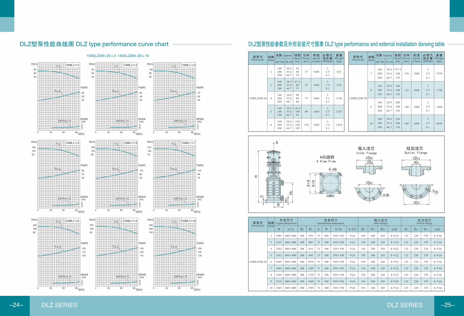
150DLZ200-20 150DLZ200-20
140
200
240
140
200
240
140
200
240
140
200
240
140
200
240
140
200
240
140
200
240
140
200
240
140
200
240
157.5
140
119
180
160
136
200
180
156
220
200
176
45
40
34
67.5
60
51
90
80
68
112.5
100
85
135
120
102
2
3
4
5
6
7
8
9
10
38.9
55.6
66.7
38.9
55.6
66.7
38.9
55.6
66.7
38.9
55.6
66.7
38.9
55.6
66.7
38.9
55.6
66.7
38.9
55.6
66.7
38.9
55.6
66.7
38.9
55.6
66.7
37
55
75
90
110
110
132
160
160
1480
1480
1480
1480
1480
1480
1480
1480
1480
3
3.5
4.1
3
3.5
4.1
3
3.5
4.1
3
3.5
4.1
3
3.5
4.1
3
3.5
4.1
3
3.5
4.1
3
3.5
4.1
3
3.5
4.1
825
970
1110
1255
1410
1570
1720
1880
2050
Pump modelFigure dimension Installation dimension Inlet flange Outlet flange
H a a H1 H2 h B b b 4- d D0 D01 D02 n-d0 D1 D11 D12 n-d1
2
3
4
5
6
7
8
9
10
1901
2107
2282
2412
2895
3005
3205
3335
3465
600 600
600 600
600 600
600 600
600 600
600 600
600 600
600 600
600 600
208
208
208
208
208
208
208
208
208
559
689
819
949
1079
1209
1339
1469
1599
73
73
73
73
73
73
73
73
73
380
380
380
380
380
380
380
380
380
550 550
550 550
550 550
550 550
550 550
550 550
550 550
550 550
550 550
24
24
24
24
24
24
24
24
24
150
150
150
150
150
150
150
150
150
240
240
240
240
240
240
240
240
240
285
285
285
285
285
285
285
285
285
8- 22
8- 22
8- 22
8- 22
8- 22
8- 22
8- 22
8- 22
8- 22
125
125
125
125
125
125
125
125
125
220
220
220
220
220
220
220
220
220
270
270
270
270
270
270
270
270
270
8- 26
8- 26
8- 26
8- 26
8- 26
8- 26
8- 26
8- 26
8- 26
150DLZ200-20

23550 550 182 75 350 480 480 200 295 340 12- 23 150 240 285 8- 23
23550 550 182 75 350 480 480 200 295 340 12- 23 150 240 285 8- 23
Pump model Pump modelSeries Series
Series
Capacity CapacityHead(m)
Head(m)
Power(kw)
Power(kw)
Speed(r/min)
Speed(r/min)(NPSH)r (NPSH)r
Weight(kg)
Weight(kg)(m /h)
3(m /h)
3(L/s) (L/s)
200DLZ280-30 200DLZ280-30
2
3
4
5
6
7
8
Pump modelFigure dimension Installation dimension Inlet flange Outlet flange
H a a H1 H2 h B b b 4- d D0 D01 D02 n-d0 D1 D11 D12 n-d1
2
3
4
5
6
7
8
200DLZ280-30
H(m)
70
60
50
40
H-Q
Pa-Q
75.54
(NPSH)r
(m)
Pa(kw)
0 35 70 105Q(l/s)
85
75
65
(NPSH)r-Q
H(m)
105
90
75
60
H-Q
Pa-Q
75.54
(NPSH)r
(m)
Pa(kw)
0 35 70 105
125
110
95
(NPSH)r-Q
H(m)
140
120
100
80
H-Q
Pa-Q
75.54
(NPSH)r
(m)
Pa(kw)
0 35 70 105
150
130
110
(NPSH)r-Q
H(m)
175
150
125
100
H-Q
Pa-Q
75.54
(NPSH)r
(m)
Pa(kw)
0 35 70 105
185
160
135
(NPSH)r-Q
H(m)
210
180
150
120
H-Q
Pa-Q
75.54
(NPSH)r
(m)
Pa(kw)
0 35 70 105
250
200
150
(NPSH)r-Q
H(m)
245
210
175
140
H-Q
Pa-Q
75.54
(NPSH)r
(m)
Pa(kw)
0 35 70 105
285
250
215
(NPSH)r-Q
H(m)
280
240
200
160
H-Q
Pa-Q
75.54
(NPSH)r
(m)
Pa(kw)
0 35 70 105
320
280
240
(NPSH)r-Q
Q(l/s) Q(l/s)
Q(l/s) Q(l/s) Q(l/s)
Q(l/s)
200
280
324
55.6
77.8
90
64
60
56
75 1480
4.2
5
5.5
1215
200
280
324
55.6
77.8
90
96
90
84
110 1480
4.2
5
5.5
1780
200
280
324
55.6
77.8
90
128
120
112
132 1480
4.2
5
5.5
2000
200
280
324
55.6
77.8
90
160
150
140
160 1480
4.2
5
5.5
2210
200
280
324
55.6
77.8
90
192
180
168
200 1480
4.2
5
5.5
2440
200
280
324
55.6
77.8
90
224
210
196
250 1480
4.2
5
5.5
3440
200
280
324
55.6
77.8
90
256
240
224
280 1480
4.2
5
5.5
3800
2200
2660
2950
3130
3310
3720
3900
624
808
992
1176
1330
1544
1728
23550 550 182 75 350 480 480 200 295 340 12- 23 150 240 285 8- 23
23550 550 182 75 350 480 480 200 295 340 12- 23 150 240 285 8- 23
23550 550 182 75 350 480 480 200 295 340 12- 23 150 240 285 8- 23
23550 550 182 75 350 480 480 200 295 340 12- 23 150 240 285 8- 23
23550 550 182 75 350 480 480 200 295 340 12- 23 150 240 285 8- 23

Pump model Pump modelSeries Series
Series
Capacity CapacityHead(m)
Head(m)
Power(kw)
Power(kw)
Speed(r/min)
Speed(r/min)(NPSH)r (NPSH)r
Weight(kg)
Weight(kg)(m /h)
3(m /h)
3(L/s) (L/s)
200DLZ300-20 200DLZ300-20
210
300
360
210
300
360
210
300
360
210
300
360
210
300
360
210
300
360
210
300
360
45
40
36
65.5
60
54.5
86
80
74
106
100
95
127
120
114
146
140
134
166.5
160
150
2
3
4
5
6
7
8
58.3
83.3
100
58.3
83.3
100
58.3
83.3
100
58.3
83.3
100
58.3
83.3
100
58.3
83.3
100
58.3
83.3
100
55
75
110
132
160
160
200
1480
1480
1480
1480
1480
1480
1480
4.2
5
5.5
4.2
5
5.5
4.2
5
5.5
4.2
5
5.5
4.2
5
5.5
4.2
5
5.5
4.2
5
5.5
1080
1340
1900
2150
2400
2550
2700
Pump modelFigure dimension Installation dimension Inlet flange Outlet flange
H a a H1 H2 h B b b 4- d D0 D01 D02 n-d0 D1 D11 D12 n-d1
2
3
4
5
6
7
8
2533
2903
3123
3273
3638
3788
3938
550 550
550 550
550 550
550 550
550 550
550 550
550 550
182
182
182
182
182
182
182
624
808
992
1176
1360
1544
1728
50
50
50
50
50
50
50
350
350
350
350
350
350
350
480 480
480 480
480 480
480 480
480 480
480 480
480 480
27
27
27
27
27
27
27
200
200
200
200
200
200
200
295
295
295
295
295
295
295
340
340
340
340
340
340
340
12- 23
12- 23
12- 23
12- 23
12- 23
12- 23
12- 23
150
150
150
150
150
150
150
240
240
240
240
240
240
240
285
285
285
285
285
285
285
200DLZ300-20
8- 23
8- 23
8- 23
8- 23
8- 23
8- 23
8- 23

Hard Link(Directly Mounted)
Soft Link(Link Plate+Vibration Isolation Pad)
Soft Link(Link Plate+Vibration Isolator)
1
2
3
4
5
6
inlet valve
flexible union
inlet manometer
outlet manometer
basis
outlet valve
1
2
3
4
5
6
7
8
inlet valve
flexible union
inlet manometer
vibration isolation pad
outlet manometer
outlet valve
link plate
basis
inlet valve
flexible union
inlet manometer
vibration isolatior
outlet manometer
outlet valve
link plate
basis
1 2 3
6
54
1 2 3
6
547
8
1 2 3
6
547
8
40DLZ
50DLZ
65DLZ
80DLZ
100DLZ
150DLZ
200DLZ
1#
2#
3#
4#
5#
6#
7#
650
650
700
600
700
850
800
600
600
650
550
650
800
740
300
305
370
410
410
550
480
18
18
26
24
24
24/26
27
14
14
17.5
17.5
22
22
23
63
55
JG2-2
JG2-2
JG3-2
JG3-2
JG4-2
JG4-2
JG4-1
12
12
16
16
20
20
20
150
150
200
200
290
290
290
130
130
170
170
260
260
260
65
65
87
87
133
133
133
9
9
9
9
9
9
9
4- 8.5
4- 8.5
4- 12.5
4- 12.5
4- 12.5
4- 12.5
4- 12.5
Link Plate
H
bb
A A
BB
4- D
4-d
Vibration Isolation Pad
20
174
174
n- dM
Hh
D1
D
Fixed with expansion blot
Link plate dimension Vibration isolator dimension
Model
A B b d D HModel
M D D1 H h n- dModel
Expansionbolt specs
M8 80
M8 80
M12 110
M12 110
M12 110
M12 110
M12 110
63
63
63
63
63
Vibration Isolator
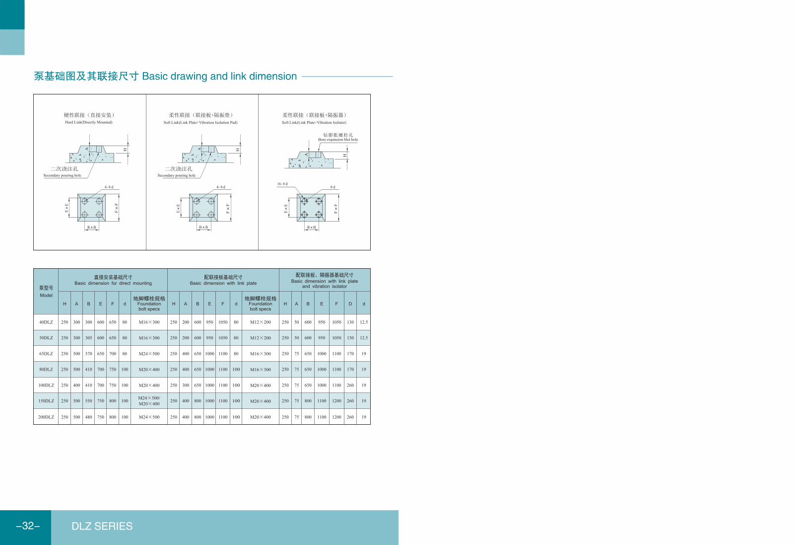
Hard Link(Directly Mounted) Soft Link(Link Plate+Vibration Isolation Pad) Soft Link(Link Plate+Vibration Isolator)
A H
Secondary pouring hole
4- d
FF
B B
EE
A H
Secondary pouring hole
4- d
FF
B B
EE
A H
d
FF
B B
EE
16- d
Model
Basic dimension for direct mounting Basic dimension with link plate Basic dimension with link plateand vibration isolator
40DLZ
50DLZ
65DLZ
80DLZ
100DLZ
150DLZ
200DLZ
250
250
250
250
250
250
250
300
300
500
500
400
500
500
300
305
370
410
410
550
480
600
600
650
700
700
750
750
650
650
700
750
750
800
800
80
80
80
100
100
100
100
250
250
250
250
250
250
250
200
200
400
400
300
400
400
600
600
650
650
650
800
800
950
950
1000
1000
1000
1000
1000
1050
1050
1100
1100
1100
1100
1100
80
80
80
100
100
100
100
250
250
250
250
250
250
250
50
50
75
75
75
75
75
600
600
650
650
650
800
800
950
950
1000
1000
1000
1100
1100
1050
1050
1100
1100
1100
1200
1200
130
130
170
170
260
260
260
12.5
12.5
19
19
19
19
19
H A B E F d H A B E F d H A B E F D dFoundationbolt specs
M16 300
M16 300
M24 500
M20 400
M20 400
M24 500
M12 200
M12 200
M16 300
M16 300
M20 400
M20 400
M20 400
Bore expansion blot hole
Foundationbolt specs
M24 500/
M20 400