Embed Size (px)
Citation preview

DLP® LightCrafter™ Display EVM GUI Tool
User's Guide
Literature Number: DLPU021BJuly 2014–Revised December 2017

2 DLPU021B–July 2014–Revised December 2017Submit Documentation Feedback
Copyright © 2014–2017, Texas Instruments Incorporated
Table of Contents
Contents
1 Overview............................................................................................................................. 32 System Requirements........................................................................................................... 33 Software Installation and Driver Installation ............................................................................ 34 User Interface Overview ........................................................................................................ 4
4.1 Information Page ......................................................................................................... 64.2 Patterns and Images..................................................................................................... 84.3 Video and Color .......................................................................................................... 94.4 Display ................................................................................................................... 104.5 IntelliBright™ ........................................................................................................... 114.6 Firmware ................................................................................................................. 124.7 Advanced Mode......................................................................................................... 14
4.7.1 Batch Files ................................................................................................... 144.7.2 Writing Batch Files .......................................................................................... 15
5 Flash Image Update ............................................................................................................ 16Revision History.......................................................................................................................... 17
3DLPU021B–July 2014–Revised December 2017Submit Documentation Feedback
Copyright © 2014–2017, Texas Instruments Incorporated
DLP® LightCrafter™ Display EVM GUI Tool
User's GuideDLPU021B–July 2014–Revised December 2017
DLP® LightCrafter™ Display EVM GUI Tool
LightCrafter, IntelliBright are trademarks of Texas Instruments.DLP is a registered trademark of Texas Instruments.Windows is a registered trademark of Microsoft Corporation.
1 OverviewThe DLP® LightCrafter™ Display evaluation module (EVM) includes a Windows®-based GUI tool used tocontrol the EVM through SPI and I2C commands. This document provides instructions on how to usefeatures provided by the GUI tool to communicate with the DLP LightCrafter Display EVM.
2 System RequirementsThe minimum recommended system requirements for the DLP LightCrafter Display EVM GUI tool are:• PC with 1.4-GHz PentiumIV CPU or higher• Windows XP SP3 or greater• 1 GB of RAM• 1920 × 1080• 45 MB of free HD space• USB port
3 Software Installation and Driver InstallationDownload the installer for the DLP LightCrafter™ Display EVM GUI tool. Execute the DLP LightCrafterDisplay EVM GUI tool v7.0 Setup.exe and follow the instructions for software installation. The driverneeded to communicate with the EVM is part of the installation, so no other installer is needed.
Table 1 shows all variations of the tool that can be installed. To install one or more variations, simplyselect the checkbox next to the EVM name during the installation of the tool.
Note: The tool used MUST match the EVM being used.
Table 1. Table of Tool Variations
EVM Simple Mode Advanced ModeDLPDLCR2010
DLP LightCrafter Display v7.0DLP LightCrafter Display v7.0 - Advanced
DLPDLCR3010DLPDLCR3010-G2
DLPDLCR4710DLP LightCrafter Display v7.0 – 4710EVM
DLPDLCR4710-G2
DLPDLCR3310 DLP LightCrafter Display v7.0 – 3310EVM DLP LightCrafter Display v7.0 – AdvancedDLPC3310EVM

User Interface Overview www.ti.com
4 DLPU021B–July 2014–Revised December 2017Submit Documentation Feedback
Copyright © 2014–2017, Texas Instruments Incorporated
DLP® LightCrafter™ Display EVM GUI Tool
4 User Interface Overview
Figure 1. Information Page for 2010/3010 EVMs
Figure 1 shows the DLP LightCrafter™ Display GUI tool. The GUI tool has six pages, which communicatewith the EVM by issuing SPI or I2C commands. To access any of the six pages, select the desired pagebutton at the top of the window. Table 2 provides a brief description of the six pages.
Table 2. Page Description
Page DescriptionInformation Lets user get the status of the EVMPatterns and Images Lets user set display patterns and images to the device and check which pattern is displayed
Video and Color Lets user modify the type of video output given to the device and choose from select colortemperatures
Display Lets user modify display and keystone settingsIntelliBright™ Lets user modify IntelliBright settings and LED current settingsFirmware Lets users back up or update the firmware on the device
In addition to the page buttons, another button opens the advanced mode of the tool. This advancedmode contains additional pages and commands that can be used with the EVM. To learn more about theadvanced mode, see Section 4.7.
To access the Menu bar while in this tool, press and release the ALT key. The tool then shows the menubar as seen in Figure 2. From this menu bar, access the Edit menu for the Preferences or the Help menufor a direct link to the user’s guide.

www.ti.com User Interface Overview
5DLPU021B–July 2014–Revised December 2017Submit Documentation Feedback
Copyright © 2014–2017, Texas Instruments Incorporated
DLP® LightCrafter™ Display EVM GUI Tool
Figure 2. Information Page with Menu Bar
The ? button in the bottom-right corner of each page is used to provide more information on that sectionand display the commands used.

User Interface Overview www.ti.com
6 DLPU021B–July 2014–Revised December 2017Submit Documentation Feedback
Copyright © 2014–2017, Texas Instruments Incorporated
DLP® LightCrafter™ Display EVM GUI Tool
4.1 Information Page
Figure 3. Information Page
Figure 3 shows the information page.
The information page lets users get status information about their EVM once it is connected and poweredon. Refer to the guide on the left portion of the Information page to see how to set up the EVM.
The status of the EVM is displayed on the top-right corner of the Information page. The EVM Statussection shows one of the following:• Ready• Connected, turned off• Not connected• Incompatible EVM connected
The Input section shows:• Video• Test patterns• Splash images
If the EVM is communicating properly with the computer, information should appear in the text fields andthe status should update.
The Information page also lets users check if any errors have occurred; checkmarks indicate specificerrors.

www.ti.com User Interface Overview
7DLPU021B–July 2014–Revised December 2017Submit Documentation Feedback
Copyright © 2014–2017, Texas Instruments Incorporated
DLP® LightCrafter™ Display EVM GUI Tool
The following commands are used to obtain information about the EVM:• Read Short Status (0xD0)• Read System Status (0xD1)• Read System Software Version (0xD2)• Read ASIC Device ID (0xD4)• Read DMD Device ID (0xD5)• Read System Temperature (0xD6)• Read Flash Build Version (0xD9)
Figure 4 shows what the Information page will look like for the 4710 EVM. Notice the board has beenupdated to reflect the 4710 EVM board and the EVM Information title now specifies that this is for 4710.
Figure 4. Information Page for 4710 EVM
Click the ? button on the bottom-right corner of the page to obtain more information about the commands.
User Interface Overview www.ti.com
8 DLPU021B–July 2014–Revised December 2017Submit Documentation Feedback
Copyright © 2014–2017, Texas Instruments Incorporated
DLP® LightCrafter™ Display EVM GUI Tool
4.2 Patterns and Images
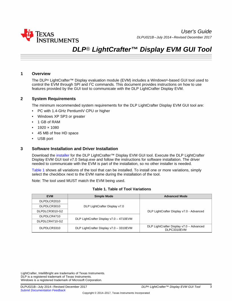
Figure 5. Patterns and Images Page
The Patterns and Images page lets users set display patterns and splash images on the connected EVM.
To set a display pattern, select the desired pattern, foreground, and background color, then click the Setbutton in the Splash Patterns section on the left side of the page. To see which display pattern isdisplayed, click the Get button.
To set a splash image, select the desired image, then click the Set button in the Splash Images section onthe right side of the page.
The following commands are used to set the display pattern:• Write Input Source Select (0x05)• Write Image Crop (0x10)• Write Test Pattern Select (0x0B)
The following command is used to get the display pattern:• Read Test Pattern Select (0x0C)
The following commands are used to set the display image:• Read Splash Screen Header (0x0F)• Write External Input Image Size (0x2E)• Write Image Crop (0x10)• Write Splash Screen Select (0x0E)• Write Input Source Select (0x05)• Write Splash Screen Execute (0x35)
For more information about the commands used in each section of the page, click the ? button on thebottom-right corner of each section.

www.ti.com User Interface Overview
9DLPU021B–July 2014–Revised December 2017Submit Documentation Feedback
Copyright © 2014–2017, Texas Instruments Incorporated
DLP® LightCrafter™ Display EVM GUI Tool
4.3 Video and Color
Figure 6. Video and Color Page
The Video and Color page has two sections: The Video Information section and the Color Temperaturesection.
When the EVM is displaying video, clicking the Get button on the Video Information section lets users seethe input size, cropping size, display size, and frame rate. Clicking the Switch to External Video buttonswitches the EVM back to video mode (HDMI).
The Color Temperature section lets users set the desired look of the EVM to cool, medium, warm, or userdefined. The Color Temperature section also lets users check the currently used look. To modify the userdefined look, refer to Section 4.6.
The following commands are used in the Video Information section:• Write Image Crop (0x10)• Write Display Size (0x12)• Write Input Image Size (0x2E)• Write External Input Source Select (0x05)
The following commands are used in the Color Temperature section:• Write RGB LED Current (0x54)• Write Look Select (0x22)• Read Look Select (0x23)
For more information about the commands used in each section of the video and color page, click the ?button on the bottom-right corner of each section.

User Interface Overview www.ti.com
10 DLPU021B–July 2014–Revised December 2017Submit Documentation Feedback
Copyright © 2014–2017, Texas Instruments Incorporated
DLP® LightCrafter™ Display EVM GUI Tool
4.4 Display
Figure 7. Display Page
The Display page gives users the option to modify display and keystone settings.
The Display Settings on the right give users the option to crop, scale, and rotate the input image. After allthe desired values are selected, clicking the Set button sends the new information to the EVM. Clickingthe Get button lets users see the current display settings on the EVM.
The Keystone Correction section lets users enable keystone on the EVM. Keystone is used when theEVM is not located on a flat surface and has a vertical tilt of ±40 degrees. Keystone correction ensuresthat the image displayed is rectangular.
Please note, not all functions shown on this page are supported on all EVMs.
The following commands are used in the Display Settings section:• Write Image Crop (0x10)• Write Display Size (0x12)• Write External Input Image Size (0x2E)• Write Display Orientation (0x14)
The following commands are used in the Keystone Correction section:• Write Keystone Correction Control (0x88)• Write Keystone Projection Pitch Angle (0xBB)
For more information about the commands used in each section of the display page, select the ? buttonon the bottom-right corner of each section.

www.ti.com User Interface Overview
11DLPU021B–July 2014–Revised December 2017Submit Documentation Feedback
Copyright © 2014–2017, Texas Instruments Incorporated
DLP® LightCrafter™ Display EVM GUI Tool
4.5 IntelliBright™
Figure 8. IntelliBright Page
Figure 8 shows the IntelliBright™ page.
The IntelliBright™ page has two sections, one to modify IntelliBright™ settings and the other to modifyLED Current settings.
IntelliBright™ is the name given to two image-processing algorithms designed to dynamically optimize thebrightness or power consumption on per frame basis. The IntelliBright™ section lets users change settingsspecific to each algorithm and check which settings are currently running on the EVM.
The EVM has three LEDs whose currents can be changed to reduce power consumption and change theperceived color temperature of the displayed image. The LED Current section lets the user modify thecurrent values and see what the EVM is using at any moment.
The following commands are used in the Display Settings section:• Write Local Area Brightness Boost Control (0x80)• Write CAIC Image Processing Control (0x84)• Write LED Output Control Method (0x50)• Read CAIC Maximum Available Power (0x57)
The following commands are used in the Keystone Correction section:• Write RGB LED Enable (0x52)• Write RGB LED Current (0x54)
For more information about the commands used in each section of the IntelliBright™ page, select the ?button on the bottom-right corner of each section.

User Interface Overview www.ti.com
12 DLPU021B–July 2014–Revised December 2017Submit Documentation Feedback
Copyright © 2014–2017, Texas Instruments Incorporated
DLP® LightCrafter™ Display EVM GUI Tool
4.6 Firmware
Figure 9. Firmware Page
The Firmware page allows users to back up and update their EVM firmware. In addition, users have theoption to modify settings in the flash image provided via ti.com through the Update Flash Image Wizard onthe right hand side of the page. Users can also modify the image in Advanced Mode, where they will havean additional option to add their own commands to the auto-initialization process.
The 3310 EVM version of the tool provides an additional option to backup or update the firmware of theon-board FPGA. This is selectable via dropdown control as seen in Figure 10. The option to backup orupdate the FPGA flash is provided only in Simple mode.

www.ti.com User Interface Overview
13DLPU021B–July 2014–Revised December 2017Submit Documentation Feedback
Copyright © 2014–2017, Texas Instruments Incorporated
DLP® LightCrafter™ Display EVM GUI Tool
Figure 10. DLPC3310 EVM Firmware Page
User Interface Overview www.ti.com
14 DLPU021B–July 2014–Revised December 2017Submit Documentation Feedback
Copyright © 2014–2017, Texas Instruments Incorporated
DLP® LightCrafter™ Display EVM GUI Tool
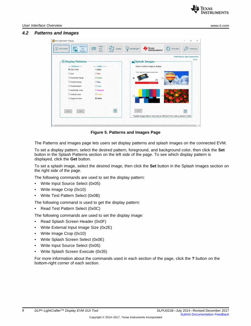
4.7 Advanced ModeAccess the tool’s advanced mode by clicking the Advanced button in simple mode or by opening theAdvanced Mode shortcut in the start menu. When opened, the tool appears as shown in Figure 11.Starting with v7.0 of the EVM tool, two versions of Advanced Mode exists. If opening from the AdvancedMode shortcut in the start menu, please look at the name to check which EVM it supports. If the EVM isnot present in the name, use the Advanced Mode without any EVMs in its name.
Figure 11. DLP LightCrafter – Advanced Mode
Table 3 shows the Advanced Mode sections.
Table 3. Advanced Mode Sections
Section Description
Menu Bar Contains the menus available for accessing other features, such asPreferences (Edit → Preferences)
Tool Bar Contains common support functions for the project based on the selected project tree page
Projector Control Pages Contains a list of tools that are used to access and send commands to the EVM. Selecting a toolopens it up in the tool pane.
Display Window Shows the actively selected tool
Output Log WindowDisplays information associated with the project. The information displayed is mainly used fordebugging purposes. The output log window has its own set of tabs (on the bottom-left side). Thisallows the user to toggle through more specific output logs without changing the active page.
To learn more about the commands used in the Advanced Mode’s pages, refer to the softwareprogrammer’s guide found at www.ti.com.
4.7.1 Batch FilesThe Batch Files page processes batch files consisting of multiple I2C (and other commands) to automatesimple tasks when developing and testing a new projector.
To run a batch file:1. Click the Choose Batch File button and select a batch file. They are typically named with an extension
of .bf.2. The batch file runs and produces output in the output window.
www.ti.com User Interface Overview
15DLPU021B–July 2014–Revised December 2017Submit Documentation Feedback
Copyright © 2014–2017, Texas Instruments Incorporated
DLP® LightCrafter™ Display EVM GUI Tool
All displayed output from the batch file is also logged to a disk file. The file will be named the same as thebatch file, but will have an extension of .log and be in the same directory as the batch file.
Options:• Long-running batch files can be stopped using the Cancel button.• Use the Resume button to continue a paused batch file.• To make the batch file stop when it encounters an error, click the Stop Batch File on first error
checkbox.• To make a popup message appear when a batch file encounters an error, click the Display message
box on error checkbox.
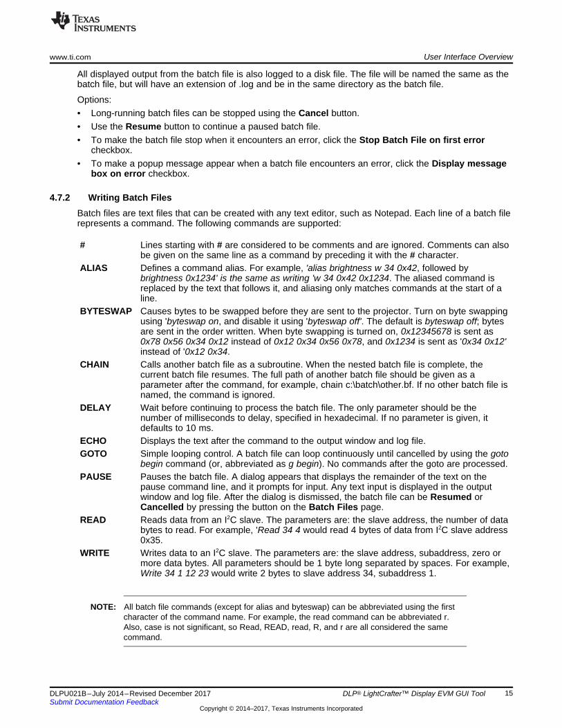
4.7.2 Writing Batch FilesBatch files are text files that can be created with any text editor, such as Notepad. Each line of a batch filerepresents a command. The following commands are supported:
# Lines starting with # are considered to be comments and are ignored. Comments can alsobe given on the same line as a command by preceding it with the # character.
ALIAS Defines a command alias. For example, 'alias brightness w 34 0x42, followed bybrightness 0x1234' is the same as writing 'w 34 0x42 0x1234. The aliased command isreplaced by the text that follows it, and aliasing only matches commands at the start of aline.
BYTESWAP Causes bytes to be swapped before they are sent to the projector. Turn on byte swappingusing 'byteswap on, and disable it using 'byteswap off'. The default is byteswap off; bytesare sent in the order written. When byte swapping is turned on, 0x12345678 is sent as0x78 0x56 0x34 0x12 instead of 0x12 0x34 0x56 0x78, and 0x1234 is sent as '0x34 0x12'instead of '0x12 0x34.
CHAIN Calls another batch file as a subroutine. When the nested batch file is complete, thecurrent batch file resumes. The full path of another batch file should be given as aparameter after the command, for example, chain c:\batch\other.bf. If no other batch file isnamed, the command is ignored.
DELAY Wait before continuing to process the batch file. The only parameter should be thenumber of milliseconds to delay, specified in hexadecimal. If no parameter is given, itdefaults to 10 ms.
ECHO Displays the text after the command to the output window and log file.GOTO Simple looping control. A batch file can loop continuously until cancelled by using the goto
begin command (or, abbreviated as g begin). No commands after the goto are processed.PAUSE Pauses the batch file. A dialog appears that displays the remainder of the text on the
pause command line, and it prompts for input. Any text input is displayed in the outputwindow and log file. After the dialog is dismissed, the batch file can be Resumed orCancelled by pressing the button on the Batch Files page.
READ Reads data from an I2C slave. The parameters are: the slave address, the number of databytes to read. For example, 'Read 34 4 would read 4 bytes of data from I2C slave address0x35.
WRITE Writes data to an I2C slave. The parameters are: the slave address, subaddress, zero ormore data bytes. All parameters should be 1 byte long separated by spaces. For example,Write 34 1 12 23 would write 2 bytes to slave address 34, subaddress 1.
NOTE: All batch file commands (except for alias and byteswap) can be abbreviated using the firstcharacter of the command name. For example, the read command can be abbreviated r.Also, case is not significant, so Read, READ, read, R, and r are all considered the samecommand.
#####################################
# SET UP SPLASH SOURCE #
#####################################
# Write: ImageCrop
W 36 10 00 00 00 00 00 05 D0 02
# Write: DisplaySize
W 36 12 80 07 38 04
# Write: InputImageSize
W 36 2E 00 05 D0 02
# Write: SplashScreenSelect
W 36 0D 03
# Write: InputSourceSelect
W 36 05 02
# 100 ms delay
W 36 DB 64 00
# Write: ImageOrientation
W 36 14 00
# WRITE LED CURRENT
W 36 54 07 01 07 01 07 01
# Write: WRITE LED ENABLE = 7. DISABLE = 0
W 36 52 07
# Write: SplashScreenExecute
W 36 35
Flash Image Update www.ti.com
16 DLPU021B–July 2014–Revised December 2017Submit Documentation Feedback
Copyright © 2014–2017, Texas Instruments Incorporated
DLP® LightCrafter™ Display EVM GUI Tool
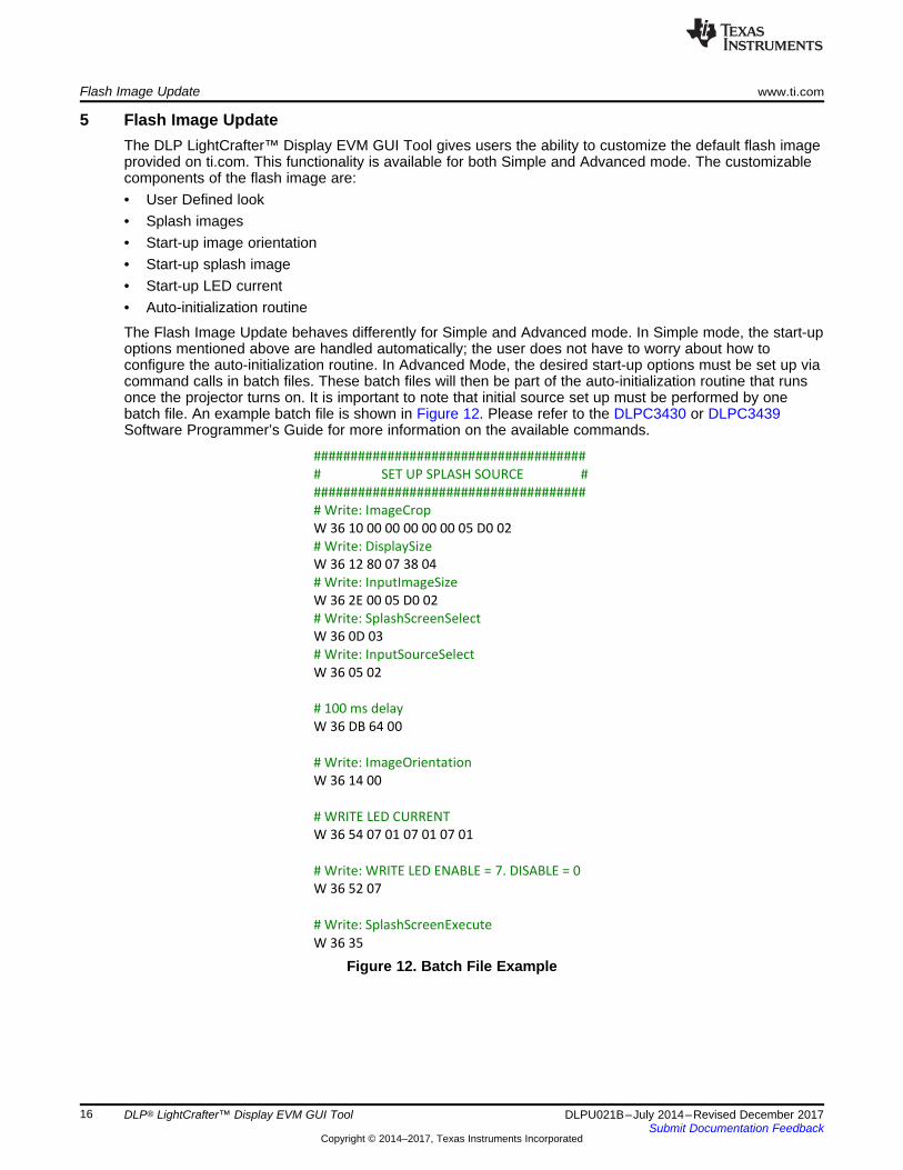
5 Flash Image UpdateThe DLP LightCrafter™ Display EVM GUI Tool gives users the ability to customize the default flash imageprovided on ti.com. This functionality is available for both Simple and Advanced mode. The customizablecomponents of the flash image are:• User Defined look• Splash images• Start-up image orientation• Start-up splash image• Start-up LED current• Auto-initialization routine
The Flash Image Update behaves differently for Simple and Advanced mode. In Simple mode, the start-upoptions mentioned above are handled automatically; the user does not have to worry about how toconfigure the auto-initialization routine. In Advanced Mode, the desired start-up options must be set up viacommand calls in batch files. These batch files will then be part of the auto-initialization routine that runsonce the projector turns on. It is important to note that initial source set up must be performed by onebatch file. An example batch file is shown in Figure 12. Please refer to the DLPC3430 or DLPC3439Software Programmer’s Guide for more information on the available commands.
Figure 12. Batch File Example

www.ti.com Revision History
17DLPU021B–July 2014–Revised December 2017Submit Documentation Feedback
Copyright © 2014–2017, Texas Instruments Incorporated
Revision History
Revision HistoryNOTE: Page numbers for previous revisions may differ from page numbers in the current version.
Changes from A Revision (February 2016) to B Revision ............................................................................................. Page
• Changed DLP LightCrafter Display EVM GUI tool from v4.0 to v7.0 in Section 3................................................ 3• Number of tool variations increased from two (previously only the 2010/3010 EVM version and the 4710 EVM version). A
table of tool variations added to Section 3 ............................................................................................. 3• Added note that not all functions are supported on all EVMs in Section 4.4 .................................................... 10• Added additional explanation of the 3310 EVM option to backup or update firmware, including Figure 10................. 12• Added description of v7.0 Advanced Mode in Section 4.7 ......................................................................... 14

Revision History www.ti.com
18 DLPU021B–July 2014–Revised December 2017Submit Documentation Feedback
Copyright © 2014–2017, Texas Instruments Incorporated
Revision History
Changes from Original (July 2014) to A Revision ................................................................................................................ Page• Updated recommended system requirement in Section 2 from 'WXGA 1280x800' to '1920 x 1080' .......................... 3• Changed DLP LightCrafter Display EVM GUI tool from v3.0 to v4.0 in Section 3................................................ 3• Terminology of 'Display images' is updated to 'splash images' ..................................................................... 8• Updated Section 4.6 description to include user specified settings ............................................................... 12• Added Section 5 Flash Image Update ................................................................................................ 16
IMPORTANT NOTICE FOR TI DESIGN INFORMATION AND RESOURCES
Texas Instruments Incorporated (‘TI”) technical, application or other design advice, services or information, including, but not limited to,reference designs and materials relating to evaluation modules, (collectively, “TI Resources”) are intended to assist designers who aredeveloping applications that incorporate TI products; by downloading, accessing or using any particular TI Resource in any way, you(individually or, if you are acting on behalf of a company, your company) agree to use it solely for this purpose and subject to the terms ofthis Notice.TI’s provision of TI Resources does not expand or otherwise alter TI’s applicable published warranties or warranty disclaimers for TIproducts, and no additional obligations or liabilities arise from TI providing such TI Resources. TI reserves the right to make corrections,enhancements, improvements and other changes to its TI Resources.You understand and agree that you remain responsible for using your independent analysis, evaluation and judgment in designing yourapplications and that you have full and exclusive responsibility to assure the safety of your applications and compliance of your applications(and of all TI products used in or for your applications) with all applicable regulations, laws and other applicable requirements. Yourepresent that, with respect to your applications, you have all the necessary expertise to create and implement safeguards that (1)anticipate dangerous consequences of failures, (2) monitor failures and their consequences, and (3) lessen the likelihood of failures thatmight cause harm and take appropriate actions. You agree that prior to using or distributing any applications that include TI products, youwill thoroughly test such applications and the functionality of such TI products as used in such applications. TI has not conducted anytesting other than that specifically described in the published documentation for a particular TI Resource.You are authorized to use, copy and modify any individual TI Resource only in connection with the development of applications that includethe TI product(s) identified in such TI Resource. NO OTHER LICENSE, EXPRESS OR IMPLIED, BY ESTOPPEL OR OTHERWISE TOANY OTHER TI INTELLECTUAL PROPERTY RIGHT, AND NO LICENSE TO ANY TECHNOLOGY OR INTELLECTUAL PROPERTYRIGHT OF TI OR ANY THIRD PARTY IS GRANTED HEREIN, including but not limited to any patent right, copyright, mask work right, orother intellectual property right relating to any combination, machine, or process in which TI products or services are used. Informationregarding or referencing third-party products or services does not constitute a license to use such products or services, or a warranty orendorsement thereof. Use of TI Resources may require a license from a third party under the patents or other intellectual property of thethird party, or a license from TI under the patents or other intellectual property of TI.TI RESOURCES ARE PROVIDED “AS IS” AND WITH ALL FAULTS. TI DISCLAIMS ALL OTHER WARRANTIES ORREPRESENTATIONS, EXPRESS OR IMPLIED, REGARDING TI RESOURCES OR USE THEREOF, INCLUDING BUT NOT LIMITED TOACCURACY OR COMPLETENESS, TITLE, ANY EPIDEMIC FAILURE WARRANTY AND ANY IMPLIED WARRANTIES OFMERCHANTABILITY, FITNESS FOR A PARTICULAR PURPOSE, AND NON-INFRINGEMENT OF ANY THIRD PARTY INTELLECTUALPROPERTY RIGHTS.TI SHALL NOT BE LIABLE FOR AND SHALL NOT DEFEND OR INDEMNIFY YOU AGAINST ANY CLAIM, INCLUDING BUT NOTLIMITED TO ANY INFRINGEMENT CLAIM THAT RELATES TO OR IS BASED ON ANY COMBINATION OF PRODUCTS EVEN IFDESCRIBED IN TI RESOURCES OR OTHERWISE. IN NO EVENT SHALL TI BE LIABLE FOR ANY ACTUAL, DIRECT, SPECIAL,COLLATERAL, INDIRECT, PUNITIVE, INCIDENTAL, CONSEQUENTIAL OR EXEMPLARY DAMAGES IN CONNECTION WITH ORARISING OUT OF TI RESOURCES OR USE THEREOF, AND REGARDLESS OF WHETHER TI HAS BEEN ADVISED OF THEPOSSIBILITY OF SUCH DAMAGES.You agree to fully indemnify TI and its representatives against any damages, costs, losses, and/or liabilities arising out of your non-compliance with the terms and provisions of this Notice.This Notice applies to TI Resources. Additional terms apply to the use and purchase of certain types of materials, TI products and services.These include; without limitation, TI’s standard terms for semiconductor products http://www.ti.com/sc/docs/stdterms.htm), evaluationmodules, and samples (http://www.ti.com/sc/docs/sampterms.htm).
Mailing Address: Texas Instruments, Post Office Box 655303, Dallas, Texas 75265Copyright © 2017, Texas Instruments Incorporated