Embed Size (px)
Citation preview

Programmer's GuideDLPU005B–October 2011–Revised November 2014
DLPC200 SPI Slave InterfaceSpecification
1 PurposeThe purpose of this document is to provide details on programming DLPC200 chipset over its SPI Slaveport. The document contains list of commands along with their detailed specifications. The commandslisted in this document provide similar functionality as compared to the DLPC200 API reference manualthat is used in controlling DLPC200 over USB port. It must be noted that not all the interfaces available inthe API reference manual are supported on SPI interface. This is because the intended use on SPI slaveport is to allow real time control functionality.
2 AssumptionsThis document does not contain details on SPI Slave hardware interface specifications. Refer to the SPISlave interface section of DLPC200 datasheet for the SPI slave hardware interface specification.
3 Reference LinksDLPC200 Data sheet, TI Literature Number DLPS014
DLPC200 API Reference Manual, TI Literature Number DLPA024
DLPC200 API Programmer's Guide, TI Literature Number DLPA014
4 OverviewThe SPI slave bus on DLPC200 is a standard synchronous four-wire serial data link that operates in fullduplex mode. There is an additional signal available to read DLPC200 busy status.
The SPI bus specifies four logic signals plus the DLPC200 BUSY status.
• SLAVE_SPI_CLK Serial Clock (Output from master)• SLAVE_SPI_MOSI Master Output, Slave Input (Output from master)• SLAVE_SPI_MISO Master Input, Slave Output (Output from DLPC200)• SLAVE_SPI_CS Slave Select (Active LOW; output from master) Additional signal• SLAVE_SPI_ACK Slave is busy (Output from DLPC200)
The data transmission over SPI bus happens in byte-by-byte mode. To begin communication the mastershould first check for SLAVE_SPI_ACK signal status LOW. In the next step the master pulls theSLAVE_SPI_CS signal to LOW. After this the master can proceed with clocking data at a frequency lessthan or equal to 5MHz. During each SPI clock cycle, a full duplex data transmission occurs; that is themaster sends a bit on the SLAVE_SPI_MOSI line; the slave reads it from that same line and the slavesends a bit on the SLAVE_SPI_MISO line; the master reads it from that same line. The master mustalways check SLAVE_SPI_ACK LOW before transmitting or receiving data byte, see Figure 1.
1DLPU005B–October 2011–Revised November 2014 DLPC200 SPI Slave Interface SpecificationSubmit Documentation Feedback
Copyright © 2011–2014, Texas Instruments Incorporated

Overview www.ti.com
Figure 1. SPI byte transfer
At a high level the commands supported over SPI interface in two categories. The first category ofcommands are called "Extended Packet ". The second category commands are called "Low LevelPacket". An Extended Packet is represented as an array of bytes with a maximum array size up to 512bytes. Commands larger than one Extended Packet size are called as multi-packet commands. For the fulllist of commands supported by the extended packet communication interface, please see the List ofContents later in this section. Similar to Extended Packet the Low Level Packet is also represented as anarray of bytes with a maximum size up to 512 bytes. These command packets allow low level control likeFlash Programming, Firmware Update, EDID update, and direct image download. For the full list ofcommands, please see List of Contents of Low Level Commands in Section 7.
2 DLPC200 SPI Slave Interface Specification DLPU005B–October 2011–Revised November 2014Submit Documentation Feedback
Copyright © 2011–2014, Texas Instruments Incorporated

www.ti.com Command/Response Protocol
5 Command/Response ProtocolThe DLPC200 SPI slave interface follows the command/response mode of operation. The SPI mastersends a command and then reads a response. It cannot directly send the next command before readingthe response for the previous command.
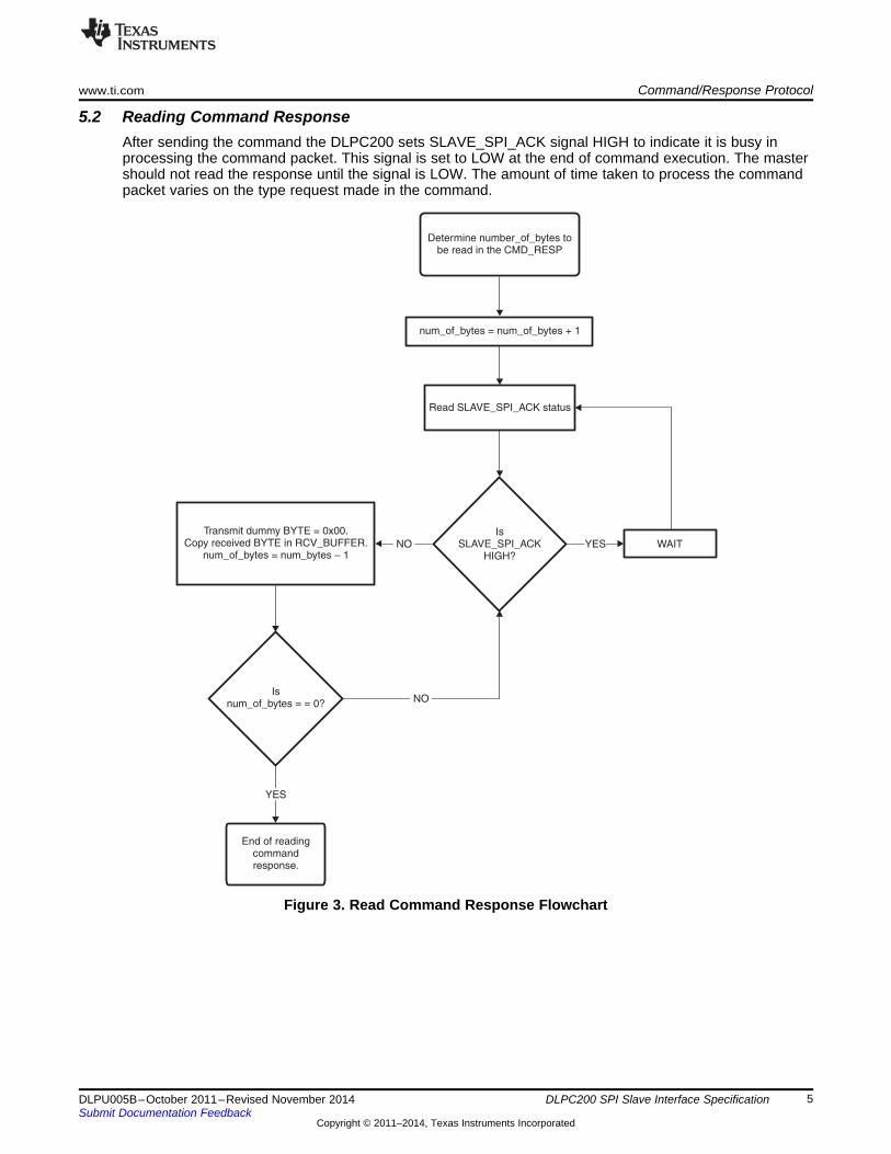
5.1 Sending CommandEach byte written by master is echoed back on the SLAVE_SPI_MISO pin of the DLPC200 controller.Basically the first byte in the command is echoed during transmission of the second byte of the command.Therefore the master has to send one extra dummy byte to read the entire command. This mechanismprovides an option for the master to validate if the command is delivered successfully. If the master findsthe command is not delivered successfully then it can resend the command again. It should be noted thatin case of an unsuccessful delivery the master still has to read the command response for theunsuccessful command. Aborting command transmission in the middle is not allowed. In case of multipacket command, the master should read the response only at the end of the last packet of the command.See Figure 2 and Figure 3 for command transmit and response flow charts.
3DLPU005B–October 2011–Revised November 2014 DLPC200 SPI Slave Interface SpecificationSubmit Documentation Feedback
Copyright © 2011–2014, Texas Instruments Incorporated

Determine number_of_bytesin the CMD store in
CMD_BUFFER
End of commandtransmission
num_of_bytes =Append dummy BYTE = 0x00 at the
end of CMD stored in CMD_BUFFER
num_of_bytes + 1
Transmit a BYTEfrom CMD_BUFFER.
Copy received BYTE inRCV_BUFFER.
num_of_bytes = num_bytes 1–
Read SLAVE_SPI_ACK status
WAITIs
SLAVE_SPI_ACKHIGH?
Isnum_of_bytes = = 0?
YES
YES
NO
NO
Command/Response Protocol www.ti.com
Figure 2. Command Transmit Flowchart
4 DLPC200 SPI Slave Interface Specification DLPU005B–October 2011–Revised November 2014Submit Documentation Feedback
Copyright © 2011–2014, Texas Instruments Incorporated
Determine number_of_bytes tobe read in the CMD_RESP
End of readingcommandresponse.
num_of_bytes = num_of_bytes + 1
Transmit dummy BYTE = 0x00.Copy received BYTE in RCV_BUFFER.
num_of_bytes = num_bytes 1–
Read SLAVE_SPI_ACK status
WAITIs
SLAVE_SPI_ACKHIGH?
Isnum_of_bytes = = 0?
YES
YES
NO
NO
www.ti.com Command/Response Protocol
5.2 Reading Command ResponseAfter sending the command the DLPC200 sets SLAVE_SPI_ACK signal HIGH to indicate it is busy inprocessing the command packet. This signal is set to LOW at the end of command execution. The mastershould not read the response until the signal is LOW. The amount of time taken to process the commandpacket varies on the type request made in the command.
Figure 3. Read Command Response Flowchart
5DLPU005B–October 2011–Revised November 2014 DLPC200 SPI Slave Interface SpecificationSubmit Documentation Feedback
Copyright © 2011–2014, Texas Instruments Incorporated

Extended Packet Definition www.ti.com
6 Extended Packet DefinitionThe structure of this 512-byte extended packet is shown below:
HEADER DATA CHECKSUMCMD1 CMD2 CMD3 CMD4 Len_LSB Len_MSB 0-505 1 byte1 byte 1 byte 1 byte 1 byte 1 byte 1 byte bytes
Definition of CMD1• WRITE – 0x02 (for set/enable/configure type functionality)• WRITE_RESP – 0x03• READ – 0x04 (for status/query type functionality)• READ_RESP – 0x05
Definition of CMD2• Unique ID assigned to CMD2 as 0xAA to identify the packet is of Extended Packet type.
Definition of CMD3• CMD3 is reserved or unused. By default CMD3 should be set to 0x00Definition of CMD4• CMD4 is meant to serve as a flag to track where in a multi-packet transfer it is. For example, there will
be many packets needed to download an ImageOrderLut (CMD ID = 0x000D). This flag will trackwhere in this packet transfer stream it is – beginning, middle, or end.– Only transfer of command – 0x00, that is single register accesses– First of many transfers – 0x01– Middle of many transfer – 0x02– Last of many transfers – 0x04
At a high level the commands are categorized as Set/Enable/Configure type or Get/GetStatus type. For allSet/Enable/Configure type commands the response is the same. The response for such commands is asexplained below.• Upon receipt of a command, the DLPC200 will send a response back to the master. If the command
was received and accepted, a value of 0x0000 would be returned in the data buffer. It would look likethe following:
CMD1 = 0x03 (WRITE_RESP)CMD2 = 0xAACMD3 = 0x00CMD4 = 0x00 (only packet of transfer)Len_LSB = 0x02Len_MSB = 0x00Data[0] = 0x00 (request processed successfully)Data[1] = 0x00 (request processed successfully)Checksum = sum of everything after CMD4 = 0x02
If the transfer was corrupted in some way then the DLPC200 will set certain bits in the data bufferData[0] and Data[1] as mentioned in the next bullet.
6 DLPC200 SPI Slave Interface Specification DLPU005B–October 2011–Revised November 2014Submit Documentation Feedback
Copyright © 2011–2014, Texas Instruments Incorporated

www.ti.com Extended Packet Definition
• The flags shaded in GRAY will be applicable for the Extended Packet response; other flags are notapplicable and will be set to ‘0’.
Data[0] (1)
Bit 0: CMD_ERR_CHK_SUM_ERROR Request packet has checksum error.Bit 1: CMD_ERR_INVALID_CMD1 Request packet has invalid CMD1 value.Bit 2: CMD_ERR_INVALID_CMD2 Request packet has invalid CMD2 value.Bit 3: CMD_ERR_INVALID_CMD3 Not applicable for Extended Packet.Bit 4: CMD_ERR_INVALID_CMD4 Request packet has invalid CMD4 value.Bit 5: CMD_ERR_INVALID_ADDRESS Not applicable for Extended Packet.Bit 6: CMD_ERR_CMD_EXE_FAILED Extended Packet processing failed.Bit 7: Will be set when a packet containing a CMD4 value of 0x01 or 0x00 isCMD_ERR_ABRUPT_TERM_OF_MUL_PKT_CMD sent after a packet containing CMD4 value of 0x01 or 0x02.
Data[1] (1) (2)
Bit 0: RFU (Reserved for Future Use) Not applicable for Extended Packet.Bit 1: RFU Not applicable for Extended Packet.Bit 2: RFU Not applicable for Extended Packet.Bit 3: CMD_ERR_INSUF_CMD_DATA Insufficient or excess data passed in the extended command packet.Bit 4: CMD_ERR_INVALID_ADD_OFST Not applicable for Extended Packet.Bit 5: CMD_ERR_FLSH_DWLD_FAIL Not applicable for Extended Packet.Bit 6: CMD_ERR_EDID_UPDATE_FAIL Not applicable for Extended Packet.Bit 7: CMD_ERR_CORRUPT_PKT_RCVD Not applicable for Extended Packet.
(1) If the packet is processed without errors then all the flags defined in Data[0] and Data[1] of response packet will be set to ‘0’ toindicate success.
(2) If error encountered while processing a command one of the flag (shaded in GRAY) along with Bit 6 is SET. In the event thatonly Bit 6 of Data[0] is SET, GetExtendedPktFailReason (CMD ID = 0x0000) can be sent to find specific reason for failure.
7DLPU005B–October 2011–Revised November 2014 DLPC200 SPI Slave Interface SpecificationSubmit Documentation Feedback
Copyright © 2011–2014, Texas Instruments Incorporated

Extended Packet Definition www.ti.com
Table 1. List of CommandsSECTION TITLENO.
6.1 GetExtendedPktFailReason (0x0000)
6.2 DisplayPatternManualStep (0x0001)
6.3 DisplayPatternManualForceFirstPattern (0x0002)
6.4 DisplayPatternAutoStepRepeatForMultiplePasses (0x0003)
6.5 DisplayStop (0x0004)
6.6 ParkDMD (0x0005)
6.7 UnparkDMD (0x0006)
6.8 SetDegammaEnable (0x0007)
6.9 HorizontalFlip (0x0008)
6.10 VerticalFlip (0x0009)
6.11 LEDintensity (0x000A)
6.12 LEDdriverEnable (0x000B)
6.13 SetLEDEnable (0x000C)
6.14 WriteImageOrderLut (0x000D)
6.15 SetDataSource (0x000E)
6.16 SetExternalTriggerEdge (0x000F)
6.17 SetTestPattern (0x0010)
6.18 SetSyncEnable (0x0011)
6.19 SyncConfigure (0x0012)
6.20 GetDMDparkState (0x0013)
6.21 GetDMDhardwareParkState (0x0014)
6.22 GetDMDsoftwareParkState (0x0015)
6.23 GetSeqRunState (0x0016)
6.24 GetEEPROMfault (0x0017)
6.25 GetDADfault (0x0018)
6.26 GetLEDdriverFault (0x0019)
6.27 GetUARTfault (0x001A)
6.28 GetFlashProgrammingMode (0x001B)
6.29 GetDADcommStatus (0x001C)
6.30 GetDMDcommStatus (0x001D)
6.31 GetLEDcommStatus (0x001E)
6.32 GetSeqDataMode (0x001F)
6.33 GetSeqDataNumPatterns (0x0020)
6.34 GetSeqDataBPP (0x0021)
6.35 GetSeqDataFrameRate (0x0022)
6.36 GetSeqDataExposure (0x0023)
6.37 GetFlashSeqCompilerVersion (0x0024)
6.38 GetDlpControllerSWVersion (0x0025)
6.39 GetDlpControllerVersion (0x0026)
6.40 GetBISTdone (0x0027)
6.41 GetBISTfail (0x0028)
6.42 GetInitFromParallelFlashFail (0x0029)
6.43 GetOverallLEDlampLitState (0x002A)
6.44 GetLEDdriverLitState (0x002B)
6.45 GetOverallLEDdriverTempTimeoutState (0x002C)
6.46 GetLEDdriverTempTimeoutState (0x002D)
6.47 GetOverallLEDdriverStrobeTimeoutState (0x002E)
6.48 GetLEDdriverStrobeTimeoutState (0x002F)
6.49 DownloadBPPfromFlashToExtMem (0x0030)
6.50 LoadSolutionFromFlash (0x0031)
6.51 PWMSeqEnable (0x0032)
8 DLPC200 SPI Slave Interface Specification DLPU005B–October 2011–Revised November 2014Submit Documentation Feedback
Copyright © 2011–2014, Texas Instruments Incorporated

www.ti.com Extended Packet Definition
Table 1. List of Commands (continued)SECTION TITLENO.
6.52 DisplayPatternAutoStepForSinglePass (0x0033)
6.53 GenerateSWVSync(0x0034)
6.54 ConfigurePWMPeriod(0x0035)
6.55 ConfigurePWMDutyCycle(0x0036)
6.1 GetExtendedPktFailReason (0x0000)This packet is used to find the reason the last Extended Packet sent failed. The two bytes allocatedData[0] Data[1] in the response packet will give some level of information which is generic in nature. Thispacket will give reason for failure specific to Extended Packets.
PACKET STRUCTURE:CMD1 = 0x04 (READ)CMD2 = 0xAA (Extended cmd packet)CMD3 = 0x00CMD4 = 0x00 (only packet of transfer)Len_LSB = 0x02Len_MSB = 0x00Data[0] = 0x00 //Extended packet IDData[1] = 0x00Checksum = sum of everything after CMD4 = 0x02
9DLPU005B–October 2011–Revised November 2014 DLPC200 SPI Slave Interface SpecificationSubmit Documentation Feedback
Copyright © 2011–2014, Texas Instruments Incorporated

Extended Packet Definition www.ti.com
Upon receipt of the packet, the DLPC200 will send a response back to the host. If the packet wasreceived and accepted the response would look like the following:
CMD1 = 0x05 (READ_RESP)CMD2 = 0xAACMD3 = 0x00CMD4 = 0x00 (only packet of transfer)Len_LSB = 0x04Len_MSB = 0x00 //Extended packet fail reasonData[0] = 0x00 (request processed successfully)Data[1] = 0x00 (request processed successfully)Data[2] = 0x00 (LSB) //Extended Packet processing failure reasonData[3] = 0x00 (LSB+1)Checksum = sum of everything after CMD4
16bit Extended Packet Processing Failure reason via Data[3] and Data[2]
0x0000: No error occurred while processing the packet.0x0001: Unknown Extended Packet ID0x0002: CMD1 mismatch that is, the packet is query or status type but packet received as write(CMD1 = 0x02) OR the packet is set/configure type while the packet received as read (CMD1 =0x04)0x0003: Invalid or wrong parameter the packet definition does not\ match.0x0004: Test Pattern display failed; system is NOT in “Video Mode”.0x0005: Load Solution failed - Device cannot be accessed0x0006: Load Solution failed - Solution offset address is invalid0x0007: Load Solution failed - Flash is not programmed0x0008: Load Solution failed - Failures detected while loading the Solution0x0009 – 0x00FF: Reserved/Unused
If the transfer was corrupted in some way then the embedded application would set certain bits in the databuffer as defined above in this document to signify this error.
NOTE: After reading the reason for failure, the error would be reset. That means sending thispacket twice one after another returns 0x0000 (no error) for the second packet.
10 DLPC200 SPI Slave Interface Specification DLPU005B–October 2011–Revised November 2014Submit Documentation Feedback
Copyright © 2011–2014, Texas Instruments Incorporated

www.ti.com Extended Packet Definition
6.2 DisplayPatternManualStep (0x0001)Repeatedly displays the next structured light image (as defined in the Image Order LUT-0x000D). Once bitplane patterns have been loaded into external memory and the DLP Control Chip is fully configured, thisfunction can be called to command the DMD and DLP Controller Chip to display the patterns as defined inthe Image Order LUT. If multiple image patterns are available for display, then each pattern can bedisplayed upon request by calling this function (repeatedly). When using an internally-programmedVSYNC, a single pattern will be displayed continuously, which allows for (human) visual inspection.
PACKET STRUCTURE:CMD1 = 0x02 (WRITE)CMD2 = 0xAA (Extended cmd packet)CMD3 = 0x00CMD4 = 0x00 (only packet of transfer)Len_LSB = 0x02Len_MSB = 0x00Data[0] = 0x01Data[1] = 0x00Checksum = sum of everything after CMD4 = 0x03
6.3 DisplayPatternManualForceFirstPattern (0x0002)Repeatedly displays the first structured light image (as defined in the Image Order LUT-0x000D). Once bitplane patterns have been loaded into external memory, and the DLP Control Chip is fully configured, thisfunction can be called to command the DMD and DLP Controller Chip to display the first pattern asdefined in the Image Order LUT. Use this function in conjunction with DLP_Display_Display PatternManual Step to start at the beginning of the Image Order LUT and index through it to see itscorresponding images.
PACKET STRUCTURE:CMD1 = 0x02 (WRITE)CMD2 = 0xAA (Extended cmd packet)CMD3 = 0x00CMD4 = 0x00 (only packet of transfer)Len_LSB = 0x02Len_MSB = 0x00Data[0] = 0x02Data[1] = 0x00Checksum = sum of everything after CMD4 = 0x04
6.4 DisplayPatternAutoStepRepeatForMultiplePasses (0x0003)Continuously displays all structured light images (as defined in Image Order LUT-0x000D), one image perframe. Once bit plane patterns have been loaded into external memory, and the DLP Control Chip is fullyconfigured, this function can be called to command the DMD and DLP Controller Chip to display thepatterns. If multiple image patterns are available for display, then the series of patterns can repeatedly bedisplayed by calling this function (once). If there are 10 patterns available for display, calling this functionwill display all 10 patterns then repeat.
11DLPU005B–October 2011–Revised November 2014 DLPC200 SPI Slave Interface SpecificationSubmit Documentation Feedback
Copyright © 2011–2014, Texas Instruments Incorporated

Extended Packet Definition www.ti.com
PACKET STRUCTURE:CMD1 = 0x02 (WRITE)CMD2 = 0xAA (Extended cmd packet)CMD3 = 0x00CMD4 = 0x00 (only packet of transfer)Len_LSB = 0x02Len_MSB = 0x00Data[0] = 0x03Data[1] = 0x00Checksum = sum of everything after CMD4 = 0x05
6.5 DisplayStop (0x0004)This function will disable the display of bit plane patterns.
PACKET STRUCTURE:CMD1 = 0x02 (WRITE)CMD2 = 0xAA (Extended cmd packet)CMD3 = 0x00CMD4 = 0x00 (only packet of transfer)Len_LSB = 0x02Len_MSB = 0x00Data[0] = 0x04Data[1] = 0x00Checksum = sum of everything after CMD4 = 0x06
6.6 ParkDMD (0x0005)Mirrors in the DMD will be parked upon receipt of this packet. LEDs will be turned off so that there will notbe any light output.
PACKET STRUCTURE:CMD1 = 0x02 (WRITE)CMD2 = 0xAA (Extended cmd packet)CMD3 = 0x00CMD4 = 0x00 (only packet of transfer)Len_LSB = 0x02Len_MSB = 0x00Data[0] = 0x05Data[1] = 0x00Checksum = sum of everything after CMD4 = 0x07
12 DLPC200 SPI Slave Interface Specification DLPU005B–October 2011–Revised November 2014Submit Documentation Feedback
Copyright © 2011–2014, Texas Instruments Incorporated

www.ti.com Extended Packet Definition
6.7 UnparkDMD (0x0006)Mirrors in the DMD will be unparked upon receipt of this packet.
PACKET STRUCTURE:CMD1 = 0x02 (WRITE)CMD2 = 0xAA (Extended cmd packet)CMD3 = 0x00CMD4 = 0x00 (only packet of transfer)Len_LSB = 0x02Len_MSB = 0x00Data[0] = 0x06Data[1] = 0x00Checksum = sum of everything after CMD4 = 0x08
NOTE: Unlike ParkDMD LEDs will not be turned ON upon receipt of this packet. This is done topreserve the user set state for the LEDs ON or OFF.
6.8 SetDegammaEnable (0x0007)Enable/disable degamma function. The degamma function is typically associated with video data and isused to linearize the light output (by removing the applied Gamma transfer function).When enablingdegamma, a corresponding LUT must have already been programmed with non-zero values. Thedegamma LUT is an output of the LOGIC application SW.
PACKET STRUCTURE:CMD1 = 0x02 (WRITE)CMD2 = 0xAA (Extended cmd packet)CMD3 = 0x00CMD4 = 0x00 (only packet of transfer)Len_LSB = 0x03Len_MSB = 0x00Data[0] = 0x07Data[1] = 0x00Data[2] = 0x01 (enable degamma)
0x00 (disable degamma)Checksum = sum of everything after CMD4 = 0x0A or 0x0B
13DLPU005B–October 2011–Revised November 2014 DLPC200 SPI Slave Interface SpecificationSubmit Documentation Feedback
Copyright © 2011–2014, Texas Instruments Incorporated

Extended Packet Definition www.ti.com
6.9 HorizontalFlip (0x0008)Enable/disable horizontal flip of the display image/pattern.
PACKET STRUCTURE:CMD1 = 0x02 (WRITE)CMD2 = 0xAA (Extended cmd packet)CMD3 = 0x00CMD4 = 0x00 (only packet of transfer)Len_LSB = 0x03Len_MSB = 0x00Data[0] = 0x08Data[1] = 0x00Data[2] = 0x01 (enable horizontal flip)
0x00 (disable horizontal flip)Checksum = sum of everything after CMD4 = 0x0B or 0x0C
6.10 VerticalFlip (0x0009)Enable/disable vertical flip of the displayed image/pattern.
PACKET STRUCTURE:CMD1 = 0x02 (WRITE)CMD2 = 0xAA (Extended cmd packet)CMD3 = 0x00CMD4 = 0x00 (only packet of transfer)Len_LSB = 0x03Len_MSB = 0x00Data[0] = 0x09Data[1] = 0x00Data[2] = 0x01 (enable vertical flip)
0x00 (disable vertical flip)Checksum = sum of everything after CMD4 = 0x0C or 0x0D
14 DLPC200 SPI Slave Interface Specification DLPU005B–October 2011–Revised November 2014Submit Documentation Feedback
Copyright © 2011–2014, Texas Instruments Incorporated

www.ti.com Extended Packet Definition
6.11 LEDintensity (0x000A)Sets the LED intensity. Upon receiving this packet, the DLP Controller SW sends a request to the LEDdriver to supply current to the LED using the value specified in the packet. For 100% intensity, the LEDwill be driven using the max allowed LED current.
For example, if the max LED current is 10 A, then sending this packet with a value of 50 (decimal) will setthe LED current to 5 A (=10 A×50/100).
PACKET STRUCTURE:CMD1 = 0x02 (WRITE)CMD2 = 0xAA (Extended cmd packet)CMD3 = 0x00CMD4 = 0x00 (only packet of transfer)Len_LSB = 0x05Len_MSB = 0x00Data[0] = 0x0AData[1] = 0x00Data[2] = 0xXX //LED Type
//0x00 – Red, 0x01 – Green, 0x02 – Blue,//0x03 – IR,//Intensity in percentage in 8.8 format // 0.0% = 0x0000 and 100.0% = 0x6400
Data[3] = 0xXX (mantissa part → integer portion of 8.8 #)Data[4] = 0xXX (decimal part → fractional portion of 8.8 #)Checksum = sum of everything after CMD4
Upon receipt of the packet, the DLPC200 will send a response back to the host. If the packet wasreceived and accepted, a value of 0x0000 will be returned in the data buffer. It would look like thefollowing:
CMD1 = 0x03 (WRITE_RESP)CMD2 = 0xAACMD3 = 0x00CMD4 = 0x00 (only packet of transfer)Len_LSB = 0x02Len_MSB = 0x00Data[0] = 0x00 (request processed successfully)Data[1] = 0x00 (request processed successfully)Checksum = sum of everything after CMD4 = 0x02
If the transfer was corrupted in some way then the embedded application would set certain bits in the databuffer as defined above in this document to signify this error.
15DLPU005B–October 2011–Revised November 2014 DLPC200 SPI Slave Interface SpecificationSubmit Documentation Feedback
Copyright © 2011–2014, Texas Instruments Incorporated

Extended Packet Definition www.ti.com
GetLEDintensity (READ)Gets the LED intensity being applied to the LEDs.
PACKET STRUCTURE:CMD1 = 0x04 (READ)CMD2 = 0xAA (Extended cmd packet)CMD3 = 0x00CMD4 = 0x00 (only packet of transfer)Len_LSB = 0x03Len_MSB = 0x00Data[0] = 0x0AData[1] = 0x00Data[2] = 0xXX //LED Type
//0x00 – Red, 0x01 – Green, 0x02 – Blue,//0x03 – IR,//Intensity in percentage in 8.8 format // 0.0% = 0x0000 and 100.0% = 0x6400
Data[3] = 0xXX (mantissa part → integer portion of 8.8 #)Data[4] = 0xXX (decimal part → fractional portion of 8.8 #)Checksum = sum of everything after CMD4
If the transfer was corrupted in some way then the embedded application would set certain bits in the databuffer as defined above in this document to signify this error.
16 DLPC200 SPI Slave Interface Specification DLPU005B–October 2011–Revised November 2014Submit Documentation Feedback
Copyright © 2011–2014, Texas Instruments Incorporated

www.ti.com Extended Packet Definition
6.12 LEDdriverEnable (0x000B)This is the debug packet for testing driver enable/disable. Send 0 to disable LED driver; send 0×01 toenable. This packet can be used to re-enable the LED driver for cases where it has "timed out" andbecome disabled because of missing strobes or over temperature.
PACKET STRUCTURE:CMD1 = 0x02 (WRITE)CMD2 = 0xAA (Extended cmd packet)CMD3 = 0x00CMD4 = 0x00 (only packet of transfer)Len_LSB = 0x03Len_MSB = 0x00Data[0] = 0x0AData[1] = 0x00Data[2] = 0x01 (enable driver)
0x00 (disable driver)Checksum = sum of everything after CMD4
6.13 SetLEDEnable (0x000C)Debug interface to enable or disable individual LED driver channel. If the PWM Seq has been built withthe specified LED, then this API can be used to disable (then re-enable) the LED.
PACKET STRUCTURE:CMD1 = 0x02 (WRITE)CMD2 = 0xAA (Extended cmd packet)CMD3 = 0x00CMD4 = 0x00 (only packet of transfer)Len_LSB = 0x04Len_MSB = 0x00Data[0] = 0x0CData[1] = 0x00Data[2] = 0xXX //LED Type 0x00 – Red, 0x01 – Green,
//0x02 – Blue, 0x03 – IR,Data[3] = 0x01 (enable LED)
0x00 (disable LED)Checksum = sum of everything after CMD4
17DLPU005B–October 2011–Revised November 2014 DLPC200 SPI Slave Interface SpecificationSubmit Documentation Feedback
Copyright © 2011–2014, Texas Instruments Incorporated

Extended Packet Definition www.ti.com
6.14 WriteImageOrderLut (0x000D)Sets the Image Order LUT. This function allows users to define the display order for image data stored inexternal memory which will be used in structured light mode. This allows the display order of the imagesto be changed without having to re-load the image data to external memory.
Example: Three 8-bit image patterns are stored in external memory as {image 0, image 1, image2}, butuser wants display order = {2, 1, 0}
The LightCommander™ system has 1Gbit NOR flash to store the patterns. On a 1Gbit flash the maximumnumber of patterns allowed are 960 for 1bpp type and 120 for 8bpp type patterns. Due to the packetstructure limitation, a maximum of 250 patterns information allowed in a packet. When the number ofpatterns exceeds 250, a multi-packet transaction will be required. Therefore maximum of 4 packets will berequired to load the Image Order LUT for entire 960 1bpp patterns in the external memory. Typically, for8bpp patterns all the 120 patterns can fit into a single packet.
Case 1:The number of patterns in Image Order LUT is ≤ 250 (single packet transaction) in the below example250 patterns shown.
PACKET STRUCTURE:CMD1 = 0x02 (WRITE)CMD2 = 0xAA (Extended cmd packet)CMD3 = 0x00CMD4 = 0x00 (only packet of transfer)Len_LSB = 0xF9Len_MSB = 0x01Data[0] = 0x0D // Extended PKT IDData[1] = 0x00 //
//Bit per pixel 1bpp = 0x01, 8bpp = 0x08 and so forthData[2] = 0xXX
//Number of images in pattern order LUTData[3] = 0xYYData[4] = 0xYY
//Image pattern display order…//1st image to be displayed
Data[5] = 0xZZ //Image pattern # as stored in the externalData[6] = 0xZZ //memory
//2nd image to be displayedData[7] = 0xZZ //Image pattern # as stored in the externalData[8] = 0xZZ //memory
//3rd Image to be displayedData[9] = 0xZZ //Image pattern # as stored in the externalData[10] = 0xZZ //memory
………//250th Image to be displayed
Data[503] = 0xZZ //Image pattern # as stored in the externalData[504] = 0xZZ //memoryChecksum = sum of everything after CMD4
18 DLPC200 SPI Slave Interface Specification DLPU005B–October 2011–Revised November 2014Submit Documentation Feedback
Copyright © 2011–2014, Texas Instruments Incorporated

www.ti.com Extended Packet Definition
Case 2:The number of patterns > 250 (multi-packet transaction). Example below shows sending 960 patternsinformation.
NOTE: Only fetch write response after sending all packets (e.g. don’t get write response after eachpacket).
PACKET STRUCTURE (1st packet):CMD1 = 0x02 (WRITE)CMD2 = 0xAA (Extended cmd packet)CMD3 = 0x00CMD4 = 0x01 (First of many)Len_LSB = 0xF9Len_MSB = 0x01Data[0] = 0x0D // Extended PKT IDData[1] = 0x00 //
//Bit per pixel 1bpp = 0x01, 8bpp = 0x08 and so forth.Data[2] = 0xXX
//Number of images in pattern order LUTData[3] = 0xYYData[4] = 0xYY
//Image pattern display order…//1st image to be displayed
Data[5] = 0xZZ //Image pattern # as stored in the externalData[6] = 0xZZ //memory
//2nd image to be displayedData[7] = 0xZZ //Image pattern # as stored in the externalData[8] = 0xZZ //memory
//3rd Image to be displayedData[9] = 0xZZ //Image pattern # as stored in the externalData[10] = 0xZZ //memory
……//250th Image to be displayed
Data[503] = 0xZZ //Image pattern # as stored in the externalData[504] = 0xZZ //memoryChecksum = sum of everything after CMD4
PACKET STRUCTURE (2nd packet):CMD1 = 0x02 (WRITE)CMD2 = 0xAA (Extended cmd packet)CMD3 = 0x00CMD4 = 0x02 (Intermediate packet)Len_LSB = 0xF9Len_MSB = 0x01Data[0] = 0x0D // Extended PKT ID
19DLPU005B–October 2011–Revised November 2014 DLPC200 SPI Slave Interface SpecificationSubmit Documentation Feedback
Copyright © 2011–2014, Texas Instruments Incorporated

Extended Packet Definition www.ti.com
Data[1] = 0x00 ////Bit per pixel 1bpp = 0x01, 8bpp = 0x08 and so forth.
Data[2] = 0xXX//Number of images in pattern order LUT
Data[3] = 0xYYData[4] = 0xYY
//Image pattern display order…//251st image to be displayed
Data[5] = 0xZZ //Image pattern # as stored in the externalData[6] = 0xZZ //memory
//252nd image to be displayedData[7] = 0xZZ //Image pattern # as stored in the externalData[8] = 0xZZ //memory
//253rd Image to be displayedData[9] = 0xZZ //Image pattern # as stored in the externalData[10] = 0xZZ //memory
………//500th Image to be displayed
Data[504] = 0xZZ //Image pattern # as stored in the externalData[505] = 0xZZ //memoryChecksum = sum of everything after CMD4
PACKET STRUCTURE (3rd packet):CMD1 = 0x02 (WRITE)CMD2 = 0xAA (Extended cmd packet)CMD3 = 0x00CMD4 = 0x02 (Intermediate packet)Len_LSB = 0xF9Len_MSB = 0x01Data[0] = 0x0D // Extended PKT IDData[1] = 0x00 //
//Bit per pixel 1bpp = 0x01, 8bpp = 0x08 and so forth..Data[2] = 0xXX
//Number of images in pattern order LUTData[3] = 0xYYData[4] = 0xYY
//Image pattern display order…//501st image to be displayed
Data[5] = 0xZZ //Image pattern # as stored in the externalData[6] = 0xZZ //memory
//502nd image to be displayedData[7] = 0xZZ //Image pattern # as stored in the externalData[8] = 0xZZ //memory
//503rd Image to be displayed
20 DLPC200 SPI Slave Interface Specification DLPU005B–October 2011–Revised November 2014Submit Documentation Feedback
Copyright © 2011–2014, Texas Instruments Incorporated

www.ti.com Extended Packet Definition
Data[9] = 0xZZ //Image pattern # as stored in the externalData[10] = 0xZZ //memory
………//750th Image to be displayed
Data[504] = 0xZZ //Image pattern # as stored in the externalData[505] = 0xZZ //memoryChecksum = sum of everything after CMD4
PACKET STRUCTURE (4th and last packet):CMD1 = 0x02 (WRITE)CMD2 = 0xAA (Extended cmd packet)CMD3 = 0x00CMD4 = 0x04 (last of many packet)Len_LSB = 0xA9Len_MSB = 0x01Data[0] = 0x0D // Extended PKT IDData[1] = 0x00 //
//Bit per pixel 1bpp = 0x01, 8bpp = 0x08 and so forth.Data[2] = 0xXX
//Number of images in pattern order LUTData[3] = 0xYYData[4] = 0xYY
//Image pattern display order…//751st image to be displayed
Data[5] = 0xZZ //Image pattern # as stored in the externalData[6] = 0xZZ //memory
//502nd image to be displayedData[7] = 0xZZ //Image pattern # as stored in the externalData[8] = 0xZZ //memory
//753rd Image to be displayedData[9] = 0xZZ //Image pattern # as stored in the externalData[10] = 0xZZ //memory
………//960th Image to be displayed
Data[423] = 0xZZ //Image pattern # as stored in the externalData[424] = 0xZZ //memoryChecksum = sum of everything after CMD4
bpp —bits-per-pixel
1bpp — Pixel represented in 1bit.For example the number of bits required to represent a 1bpp XGA pattern will be 1024*768*1 =786432 bits
21DLPU005B–October 2011–Revised November 2014 DLPC200 SPI Slave Interface SpecificationSubmit Documentation Feedback
Copyright © 2011–2014, Texas Instruments Incorporated

Extended Packet Definition www.ti.com
8bpp —Pixel represented in 8bitsFor example the number of bits required to represent a 8bpp XGA pattern will be 1024*768*8 =6291456 bits
NOTE: Sending wrong info on bpp and/or number of images (more than actual patterns loaded inthe DDR2 memory) and/or wrong pattern slot number will result in displaying corrupted data.
NOTE: On encountering an invalid slot number (slot number > 959) no further processing of thepacket will be done. GetExtendedPktFailReason packet will return the appropriate error codetht is, 0x0003: Invalid or wrong parameter.
22 DLPC200 SPI Slave Interface Specification DLPU005B–October 2011–Revised November 2014Submit Documentation Feedback
Copyright © 2011–2014, Texas Instruments Incorporated

www.ti.com Extended Packet Definition
6.15 SetDataSource (0x000E)Sets the input data source.
The data source can be one of the following:
0: DVI // DVI (port 0)1: EXP // Expansion port (Port-1)2: TPG // Test Pattern Generator
//Frame triggers VSYNC3: SL_AUTO // Structured Light Auto gen4: SL_EXT3P3 // Structured Light External trigger 3.3V5: SL_EXT1P8 // Structured Light External trigger 1.8V6: SL_SW // Structured Light Software generated trigger
PACKET STRUCTURE:CMD1 = 0x02 (WRITE)CMD2 = 0xAA (Extended cmd packet)CMD3 = 0x00CMD4 = 0x00 (only packet of transfer)Len_LSB = 0x03Len_MSB = 0x00Data[0] = 0x0EData[1] = 0x00Data[2] = 0xXX (Data source value between 0 – 6, refer above description)Checksum = sum of everything after CMD4
6.16 SetExternalTriggerEdge (0x000F)Programs the trigger edge.
PACKET STRUCTURE:CMD1 = 0x02 (WRITE)CMD2 = 0xAA (Extended cmd packet)CMD3 = 0x00CMD4 = 0x00 (only packet of transfer)Len_LSB = 0x03Len_MSB = 0x00Data[0] = 0x0FData[1] = 0x00Data[2] = 0x00 (Falling Edge)
0x01 (Rising Edge)Checksum = sum of everything after CMD4
23DLPU005B–October 2011–Revised November 2014 DLPC200 SPI Slave Interface SpecificationSubmit Documentation Feedback
Copyright © 2011–2014, Texas Instruments Incorporated

Extended Packet Definition www.ti.com
6.17 SetTestPattern (0x0010)When the input source is Test Pattern Generator, this command programs which test pattern to display.Test Patterns can be displayed in Video Mode only.
PACKET STRUCTURE:CMD1 = 0x02 (WRITE)CMD2 = 0xAA (Extended cmd packet)CMD3 = 0x00CMD4 = 0x00 (only packet of transfer)Len_LSB = 0x06Len_MSB = 0x00Data[0] = 0x10 //Extended packet IDData[1] = 0x00Data[2] = 0xYY (Desired Pattern to be displayed)
// 0x00 - Solid Field.// 0x01 - Horizontal Ramp.// 0x02 - Vertical Ramp.// 0x03 - Horizontal Lines.// 0x04 - Diagonal Lines.// 0x05 - Vertical Lines.// 0x06 - Horizontal Stripes.// 0x07 - Vertical Stripes.// 0x08 - Grid.// 0x09 - Checkerboard.
Data[3] = 0xZZ (Test Pattern Color)//0x00 - Black//0x01 - Red//0x02 - Green//0x03 - Blue//0x04 - Yellow//0x05 - Cyan//0x06 - Magenta//0x07 – White//Pattern repeat frequency (16bit value)
Data[4] = 0xMM (LSB)Data[5] = 0xMM (LSB+1)
//This is number of times to spatially repeat the//pattern.//For example, valid values for XGA type device are//1,2,4,8,16,32,64,128,256,512. Horizontal patterns//will repeat according to this parameter. Due//to the non power of 2 vertical DMD resolutions,//vertical patterns is only loosely based on this//frequency.
Checksum = sum of everything after CMD4
24 DLPC200 SPI Slave Interface Specification DLPU005B–October 2011–Revised November 2014Submit Documentation Feedback
Copyright © 2011–2014, Texas Instruments Incorporated

www.ti.com Extended Packet Definition
6.18 SetSyncEnable (0x0011)There are three sync outputs available for the external source trigger. This packet used to enable/disablethe specified output sync.
PACKET STRUCTURE:CMD1 = 0x02 (WRITE)CMD2 = 0xAA (Extended cmd packet)CMD3 = 0x00CMD4 = 0x00 (only packet of transfer)Len_LSB = 0x04Len_MSB = 0x00Data[0] = 0x11 //Extended packet IDData[1] = 0x00//Sync numberData[2] = 0xXX //Sync number to enable between 1 to 3
// the values can be 1, 2, 3Data[3] = 0x01 (enable Sync)
0x00 (disable Sync)Checksum = sum of everything after CMD4
Upon receipt of the packet, the DLPC200 will send a response back to the host. If the packet wasreceived and accepted, a value of 0x0000 will be returned in the data buffer. It would look like thefollowing:
CMD1 = 0x03 (WRITE_RESP)CMD2 = 0x00CMD3 = 0x00CMD4 = 0x00 (only packet of transfer)Len_LSB = 0x02Len_MSB = 0x00Data[0] = 0x00 (request processed successfully)Data[1] = 0x00 (request processed successfully)Checksum = sum of everything after CMD4 = 0x02
If the transfer was corrupted in some way then the embedded application would set certain bits in the databuffer as defined above in this document to signify this error.
6.19 SyncConfigure (0x0012)There are three sync outputs available for the external source trigger. This packet is used to configure thespecified output sync.
PACKET STRUCTURE:CMD1 = 0x02 (WRITE)CMD2 = 0xAA (Extended cmd packet)CMD3 = 0x00CMD4 = 0x00 (only packet of transfer)Len_LSB = 0x0CLen_MSB = 0x00Data[0] = 0x12 //Extended packet ID
25DLPU005B–October 2011–Revised November 2014 DLPC200 SPI Slave Interface SpecificationSubmit Documentation Feedback
Copyright © 2011–2014, Texas Instruments Incorporated

Extended Packet Definition www.ti.com
Data[1] = 0x00//Sync number to enable/disableData[2] = 0xXX //Sync number to enable between 1 to 3
// the values can be 1, 2, 3//Sync polarityData[3] = 0x01 (Positive polarity)
0x00 (Negative polarity)//Output sync delay in microseconds (32bit value)Data[4] = 0xXX (LSB)Data[5] = 0xXX (LSB+1)Data[6] = 0xXX (LSB+2)Data[7] = 0xXX (LSB+3) //Output sync pulse width in microseconds (32bit value)Data[8] = 0xXX (LSB)Data[9] = 0xXX (LSB+1)Data[10] = 0xXX (LSB+2)Data[11] = 0xXX (LSB+3)Checksum = sum of everything after CMD4
26 DLPC200 SPI Slave Interface Specification DLPU005B–October 2011–Revised November 2014Submit Documentation Feedback
Copyright © 2011–2014, Texas Instruments Incorporated

www.ti.com Extended Packet Definition
6.20 GetDMDparkState (0x0013)Gets the DMD park state.
PACKET STRUCTURE:CMD1 = 0x04 (READ)CMD2 = 0xAA (Extended cmd packet)CMD3 = 0x00CMD4 = 0x00 (only packet of transfer)Len_LSB = 0x02Len_MSB = 0x00Data[0] = 0x13Data[1] = 0x00Checksum = sum of everything after CMD4 = 0x15
Upon receipt of the packet, the DLPC200 will send a response back to the host. If the packet wasreceived and accepted the response would look like the following:
CMD1 = 0x05 (READ_RESP)CMD2 = 0xAACMD3 = 0x00CMD4 = 0x00 (only packet of transfer)Len_LSB = 0x03Len_MSB = 0x00Data[0] = 0x00 (request processed successfully)Data[1] = 0x00 (request processed successfully)Data[2] = 0xXX // DMD Park state
//0x00 – DMD is unparked//0x01 – DMD is parked
Checksum = sum of everything after CMD4
If the transfer was corrupted in some way then the embedded application would set certain bits in the databuffer as defined above in this document to signify this error.
6.21 GetDMDhardwareParkState (0x0014)Helps in determining if DMD isparked by the hardware switch.
PACKET STRUCTURE:CMD1 = 0x04 (READ)CMD2 = 0xAA (Extended cmd packet)CMD3 = 0x00CMD4 = 0x00 (only packet of transfer)Len_LSB = 0x02Len_MSB = 0x00Data[0] = 0x14 //Extended packet IDData[1] = 0x00Checksum = sum of everything after CMD4 = 0x16
Upon receipt of the packet, the DLPC200 will send a response back to the host. If the packet wasreceived and accepted the response would look like the following:
27DLPU005B–October 2011–Revised November 2014 DLPC200 SPI Slave Interface SpecificationSubmit Documentation Feedback
Copyright © 2011–2014, Texas Instruments Incorporated

Extended Packet Definition www.ti.com
CMD1 = 0x05 (READ_RESP)CMD2 = 0xAACMD3 = 0x00CMD4 = 0x00 (only packet of transfer)Len_LSB = 0x03Len_MSB = 0x00Data[0] = 0x00 (request processed successfully)Data[1] = 0x00 (request processed successfully)Data[2] = 0xXX // DMD Park state
//0x00 – hardware switch not activated//0x01 – DMD park activated by hardware switch
Checksum = sum of everything after CMD4
If the transfer was corrupted in some way then the embedded application would set certain bits in the databuffer as defined above in this document to signify this error.
6.22 GetDMDsoftwareParkState (0x0015)Determines if the DMD parked state is caused by a software issued command (that is ParkDMD –0x0005).
PACKET STRUCTURE:CMD1 = 0x04 (READ)CMD2 = 0xAA (Extended cmd packet)CMD3 = 0x00CMD4 = 0x00 (only packet of transfer)Len_LSB = 0x02Len_MSB = 0x00Data[0] = 0x15 //Extended packet IDData[1] = 0x00Checksum = sum of everything after CMD4 = 0x17
Upon receipt of the packet, the DLPC200 will send a response back to the host. If the packet wasreceived and accepted the response would look like the following:
CMD1 = 0x05 (READ_RESP)CMD2 = 0xAACMD3 = 0x00CMD4 = 0x00 (only packet of transfer)Len_LSB = 0x03Len_MSB = 0x00Data[0] = 0x00 (request processed successfully)Data[1] = 0x00 (request processed successfully)Data[2] = 0xXX // DMD Park state
//0x00 – DMD park not requested by the software//0x01 – DMD park requested by the software
Checksum = sum of everything after CMD4
28 DLPC200 SPI Slave Interface Specification DLPU005B–October 2011–Revised November 2014Submit Documentation Feedback
Copyright © 2011–2014, Texas Instruments Incorporated

www.ti.com Extended Packet Definition
If the transfer was corrupted in some way then the embedded application would set certain bits in the databuffer as defined above in this document to signify this error.
6.23 GetSeqRunState (0x0016)Gets the PWM sequence run state: running or stopped.
PACKET STRUCTURE:CMD1 = 0x04 (READ)CMD2 = 0xAA (Extended cmd packet)CMD3 = 0x00CMD4 = 0x00 (only packet of transfer)Len_LSB = 0x02Len_MSB = 0x00Data[0] = 0x16 //Extended packet IDData[1] = 0x00Checksum = sum of everything after CMD4 = 0x18
Upon receipt of the packet, the DLPC200 will send a response back to the host. If the packet wasreceived and accepted the response would look like the following:
CMD1 = 0x05 (READ_RESP)CMD2 = 0xAACMD3 = 0x00CMD4 = 0x00 (only packet of transfer)Len_LSB = 0x03Len_MSB = 0x00Data[0] = 0x00 (request processed successfully)Data[1] = 0x00 (request processed successfully)Data[2] = 0xXX // DMD Park state
//0x00 – PWM sequence stopped//0x01 – PWM sequence running
Checksum = sum of everything after CMD4
If the transfer was corrupted in some way then the embedded application would set certain bits in the databuffer as defined above in this document to signify this error.
6.24 GetEEPROMfault (0x0017)The EEPROM device stores the EDID info. This packet is used to check if an EEPROM fault is detected.
PACKET STRUCTURE:CMD1 = 0x04 (READ)CMD2 = 0xAA (Extended cmd packet)CMD3 = 0x00CMD4 = 0x00 (only packet of transfer)Len_LSB = 0x02Len_MSB = 0x00Data[0] = 0x17 //Extended packet IDData[1] = 0x00Checksum = sum of everything after CMD4 = 0x19
29DLPU005B–October 2011–Revised November 2014 DLPC200 SPI Slave Interface SpecificationSubmit Documentation Feedback
Copyright © 2011–2014, Texas Instruments Incorporated

Extended Packet Definition www.ti.com
Upon receipt of the packet, the DLPC200 will send a response back to the host. If the packet wasreceived and accepted the response would look like the following:
CMD1 = 0x05 (READ_RESP)CMD2 = 0xAACMD3 = 0x00CMD4 = 0x00 (only packet of transfer)Len_LSB = 0x03Len_MSB = 0x00Data[0] = 0x00 (request processed successfully)Data[1] = 0x00 (request processed successfully)Data[2] = 0xXX // EEPROM fault
//0x00 – no fault detected//0x01 – fault detected
Checksum = sum of everything after CMD4
If the transfer was corrupted in some way then the embedded application would set certain bits in the databuffer as defined above in this document to signify this error.
6.25 GetDADfault (0x0018)Checks for DLPA200 (aka DAD = Analog reset driver) fault.
PACKET STRUCTURE:CMD1 = 0x04 (READ)CMD2 = 0xAA (Extended cmd packet)CMD3 = 0x00CMD4 = 0x00 (only packet of transfer)Len_LSB = 0x02Len_MSB = 0x00Data[0] = 0x18 //Extended packet IDData[1] = 0x00Checksum = sum of everything after CMD4 = 0x1A
Upon receipt of the packet, the DLPC200 will send a response back to the host. If the packet wasreceived and accepted the response would look like the following:
CMD1 = 0x05 (READ_RESP)CMD2 = 0xAACMD3 = 0x00CMD4 = 0x00 (only packet of transfer)Len_LSB = 0x03Len_MSB = 0x00Data[0] = 0x00 (request processed successfully)Data[1] = 0x00 (request processed successfully)Data[2] = 0xXX // DAD fault
//0x00 – no fault detected//0x01 – fault detected
Checksum = sum of everything after CMD4
30 DLPC200 SPI Slave Interface Specification DLPU005B–October 2011–Revised November 2014Submit Documentation Feedback
Copyright © 2011–2014, Texas Instruments Incorporated

www.ti.com Extended Packet Definition
If the transfer was corrupted in some way then the embedded application would set certain bits in the databuffer as defined above in this document to signify this error.
6.26 GetLEDdriverFault (0x0019)Checks for LED Driver fault.
PACKET STRUCTURE:CMD1 = 0x04 (READ)CMD2 = 0xAA (Extended cmd packet)CMD3 = 0x00CMD4 = 0x00 (only packet of transfer)Len_LSB = 0x02Len_MSB = 0x00Data[0] = 0x19 //Extended packet IDData[1] = 0x00Checksum = sum of everything after CMD4 = 0x1B
Upon receipt of the packet, the DLPC200 will send a response back to the host. If the packet wasreceived and accepted the response would look like the following:
CMD1 = 0x05 (READ_RESP)CMD2 = 0xAACMD3 = 0x00CMD4 = 0x00 (only packet of transfer)Len_LSB = 0x03Len_MSB = 0x00Data[0] = 0x00 (request processed successfully)Data[1] = 0x00 (request processed successfully)Data[2] = 0xXX // LED Driver fault
//0x00 – no fault detected//0x01 – fault detected
Checksum = sum of everything after CMD4
If the transfer was corrupted in some way then the embedded application would set certain bits in the databuffer as defined above in this document to signify this error.
6.27 GetUARTfault (0x001A)Checks for UART port fault.
PACKET STRUCTURE:CMD1 = 0x04 (READ)CMD2 = 0xAA (Extended cmd packet)CMD3 = 0x00CMD4 = 0x00 (only packet of transfer)Len_LSB = 0x02Len_MSB = 0x00Data[0] = 0x1A //Extended packet IDData[1] = 0x00Checksum = sum of everything after CMD4 = 0x1C
31DLPU005B–October 2011–Revised November 2014 DLPC200 SPI Slave Interface SpecificationSubmit Documentation Feedback
Copyright © 2011–2014, Texas Instruments Incorporated

Extended Packet Definition www.ti.com
Upon receipt of the packet, the DLPC200 will send a response back to the host. If the packet wasreceived and accepted the response would look like the following:
CMD1 = 0x05 (READ_RESP)CMD2 = 0xAACMD3 = 0x00CMD4 = 0x00 (only packet of transfer)Len_LSB = 0x03Len_MSB = 0x00Data[0] = 0x00 (request processed successfully)Data[1] = 0x00 (request processed successfully)Data[2] = 0xXX // UART port fault
//0x00 – no fault detected//0x01 – fault detected
Checksum = sum of everything after CMD4
If the transfer was corrupted in some way then the embedded application would set certain bits in the databuffer as defined above in this document to signify this error.
6.28 GetFlashProgrammingMode (0x001B)Checks if the system is in flash programming mode.
PACKET STRUCTURE:CMD1 = 0x04 (READ)CMD2 = 0xAA (Extended cmd packet)CMD3 = 0x00CMD4 = 0x00 (only packet of transfer)Len_LSB = 0x02Len_MSB = 0x00Data[0] = 0x1B //Extended packet IDData[1] = 0x00Checksum = sum of everything after CMD4 = 0x1D
Upon receipt of the packet, the DLPC200 will send a response back to the host. If the packet wasreceived and accepted the response would look like the following:
CMD1 = 0x05 (READ_RESP)CMD2 = 0xAACMD3 = 0x00CMD4 = 0x00 (only packet of transfer)Len_LSB = 0x03Len_MSB = 0x00Data[0] = 0x00 (request processed successfully)Data[1] = 0x00 (request processed successfully)Data[2] = 0xXX // Flash programming mode
//0x00 – normal mode//0x01 – flash programming mode
Checksum = sum of everything after CMD4
32 DLPC200 SPI Slave Interface Specification DLPU005B–October 2011–Revised November 2014Submit Documentation Feedback
Copyright © 2011–2014, Texas Instruments Incorporated

www.ti.com Extended Packet Definition
If the transfer was corrupted in some way then the embedded application would set certain bits in the databuffer as defined above in this document to signify this error.
6.29 GetDADcommStatus (0x001C)Gets DLPA200/DAD SPI communication status.
PACKET STRUCTURE:CMD1 = 0x04 (READ)CMD2 = 0xAA (Extended cmd packet)CMD3 = 0x00CMD4 = 0x00 (only packet of transfer)Len_LSB = 0x02Len_MSB = 0x00Data[0] = 0x1C //Extended packet IDData[1] = 0x00Checksum = sum of everything after CMD4 = 0x1E
Upon receipt of the packet, the DLPC200 will send a response back to the host. If the packet wasreceived and accepted the response would look like the following:
CMD1 = 0x05 (READ_RESP)CMD2 = 0xAACMD3 = 0x00CMD4 = 0x00 (only packet of transfer)Len_LSB = 0x03Len_MSB = 0x00Data[0] = 0x00 (request processed successfully)Data[1] = 0x00 (request processed successfully)Data[2] = 0xXX // DAD SPI communication status
//0x00 – OK//0x01 – SPI failure detected
Checksum = sum of everything after CMD4
If the transfer was corrupted in some way then the embedded application would set certain bits in the databuffer as defined above in this document to signify this error.
6.30 GetDMDcommStatus (0x001D)Gets DMD SPI communication status.
PACKET STRUCTURE:CMD1 = 0x04 (READ)CMD2 = 0xAA (Extended cmd packet)CMD3 = 0x00CMD4 = 0x00 (only packet of transfer)Len_LSB = 0x02Len_MSB = 0x00Data[0] = 0x1D //Extended packet IDData[1] = 0x00Checksum = sum of everything after CMD4 = 0x1F
33DLPU005B–October 2011–Revised November 2014 DLPC200 SPI Slave Interface SpecificationSubmit Documentation Feedback
Copyright © 2011–2014, Texas Instruments Incorporated

Extended Packet Definition www.ti.com
Upon receipt of the packet, the DLPC200 will send a response back to the host. If the packet wasreceived and accepted the response would look like the following:
CMD1 = 0x05 (READ_RESP)CMD2 = 0xAACMD3 = 0x00CMD4 = 0x00 (only packet of transfer)Len_LSB = 0x03Len_MSB = 0x00Data[0] = 0x00 (request processed successfully)Data[1] = 0x00 (request processed successfully)Data[2] = 0xXX // DMD SPI communication status
//0x00 – OK//0x01 – SPI failure detected
Checksum = sum of everything after CMD4
If the transfer was corrupted in some way then the embedded application would set certain bits in the databuffer as defined above in this document to signify this error.
6.31 GetLEDcommStatus (0x001E)Gets LED Driver SPI communication status.
PACKET STRUCTURE:CMD1 = 0x04 (READ)CMD2 = 0xAA (Extended cmd packet)CMD3 = 0x00CMD4 = 0x00 (only packet of transfer)Len_LSB = 0x02Len_MSB = 0x00Data[0] = 0x1E //Extended packet IDData[1] = 0x00Checksum = sum of everything after CMD4 = 0x20
Upon receipt of the packet, the DLPC200 will send a response back to the host. If the packet wasreceived and accepted the response would look like the following:
CMD1 = 0x05 (READ_RESP)CMD2 = 0xAACMD3 = 0x00CMD4 = 0x00 (only packet of transfer)Len_LSB = 0x03Len_MSB = 0x00Data[0] = 0x00 (request processed successfully)Data[1] = 0x00 (request processed successfully)Data[2] = 0xXX // LED Driver SPI communication status
//0x00 – OK//0x01 – SPI failure detected
Checksum = sum of everything after CMD4
34 DLPC200 SPI Slave Interface Specification DLPU005B–October 2011–Revised November 2014Submit Documentation Feedback
Copyright © 2011–2014, Texas Instruments Incorporated

www.ti.com Extended Packet Definition
If the transfer was corrupted in some way then the embedded application would set certain bits in the databuffer as defined above in this document to signify this error.
6.32 GetSeqDataMode (0x001F)Gets sequence data mode. Meta data describing the currently loaded PWM sequence.
PACKET STRUCTURE:CMD1 = 0x04 (READ)CMD2 = 0xAA (Extended cmd packet)CMD3 = 0x00CMD4 = 0x00 (only packet of transfer)Len_LSB = 0x02Len_MSB = 0x00Data[0] = 0x1F //Extended packet IDData[1] = 0x00Checksum = sum of everything after CMD4 = 0x21
Upon receipt of the packet, the DLPC200 will send a response back to the host. If the packet wasreceived and accepted the response would look like the following:
CMD1 = 0x05 (READ_RESP)CMD2 = 0xAACMD3 = 0x00CMD4 = 0x00 (only packet of transfer)Len_LSB = 0x03Len_MSB = 0x00Data[0] = 0x00 (request processed successfully)Data[1] = 0x00 (request processed successfully)Data[2] = 0xXX // Sequence data Mode
//0x00 – Structured light, non real-time input.//0x01 – Structured light, real-time input.//0x02 - Video mode.//0x03 - Video plus Structured Light.//0x04 - Object mode.
Checksum = sum of everything after CMD4
If the transfer was corrupted in some way then the embedded application would set certain bits in the databuffer as defined above in this document to signify this error.
6.33 GetSeqDataNumPatterns (0x0020)Gets sequence data - number of patterns per frame. Meta data describing the number of patterns perframe is used for building currently loaded PWM sequences.
PACKET STRUCTURE:CMD1 = 0x04 (READ)CMD2 = 0xAA (Extended cmd packet)CMD3 = 0x00CMD4 = 0x00 (only packet of transfer)Len_LSB = 0x02
35DLPU005B–October 2011–Revised November 2014 DLPC200 SPI Slave Interface SpecificationSubmit Documentation Feedback
Copyright © 2011–2014, Texas Instruments Incorporated

Extended Packet Definition www.ti.com
Len_MSB = 0x00Data[0] = 0x20 //Extended packet IDData[1] = 0x00Checksum = sum of everything after CMD4 = 0x22
Upon receipt of the packet, the DLPC200 will send a response back to the host. If the packet wasreceived and accepted the response would look like the following:
CMD1 = 0x05 (READ_RESP)CMD2 = 0xAACMD3 = 0x00CMD4 = 0x00 (only packet of transfer)Len_LSB = 0x03Len_MSB = 0x00Data[0] = 0x00 (request processed successfully)Data[1] = 0x00 (request processed successfully)//Number of patterns output per frame (16bit value)Data[2] = 0xXX (LSB)Data[3] = 0xXX (LSB+1)Checksum = sum of everything after CMD4
If the transfer was corrupted in some way then the embedded application would set certain bits in the databuffer as defined above in this document to signify this error.
6.34 GetSeqDataBPP (0x0021)Gets sequence data - number of bits per pixel. Meta data describing the BPP used for building thecurrently loaded PWM sequence. BPP is only applicable in structured light mode.
PACKET STRUCTURE:CMD1 = 0x04 (READ)CMD2 = 0xAA (Extended cmd packet)CMD3 = 0x00CMD4 = 0x00 (only packet of transfer)Len_LSB = 0x02Len_MSB = 0x00Data[0] = 0x21 //Extended packet IDData[1] = 0x00Checksum = sum of everything after CMD4 = 0x23
Upon receipt of the packet, the DLPC200 will send a response back to the host. If the packet wasreceived and accepted the response would look like the following:
CMD1 = 0x05 (READ_RESP)CMD2 = 0xAACMD3 = 0x00CMD4 = 0x00 (only packet of transfer)Len_LSB = 0x03Len_MSB = 0x00Data[0] = 0x00 (request processed successfully)
36 DLPC200 SPI Slave Interface Specification DLPU005B–October 2011–Revised November 2014Submit Documentation Feedback
Copyright © 2011–2014, Texas Instruments Incorporated

www.ti.com Extended Packet Definition
Data[1] = 0x00 (request processed successfully)Data[2] = 0xXX // Number of bits per pixel (bpp)
//For example 8bpp the value returned would be//0x08, similarly for 1bpp it will be 0x01
Checksum = sum of everything after CMD4
If the transfer was corrupted in some way then the embedded application would set certain bits in the databuffer as defined above in this document to signify this error.
6.35 GetSeqDataFrameRate (0x0022)Meta data describing the frame rate (in Hz) used for building the currently loaded PWM sequence.
PACKET STRUCTURE:CMD1 = 0x04 (READ)CMD2 = 0xAA (Extended cmd packet)CMD3 = 0x00CMD4 = 0x00 (only packet of transfer)Len_LSB = 0x02Len_MSB = 0x00Data[0] = 0x22 //Extended packet IDData[1] = 0x00Checksum = sum of everything after CMD4 = 0x24
Upon receipt of the packet, the DLPC200 will send a response back to the host. If the packet wasreceived and accepted the response would look like the following:
CMD1 = 0x05 (READ_RESP)CMD2 = 0xAACMD3 = 0x00CMD4 = 0x00 (only packet of transfer)Len_LSB = 0x03Len_MSB = 0x00Data[0] = 0x00 (request processed successfully)Data[1] = 0x00 (request processed successfully)//Sequence frame rate 20bit value in u16.4 formatData[2] = 0xXX (LSB)Data[3] = 0xXX (LSB+1)Data[4] = 0xXX (LSB+2)Checksum = sum of everything after CMD4
If the transfer was corrupted in some way then the embedded application would set certain bits in the databuffer as defined above in this document to signify this error.
6.36 GetSeqDataExposure (0x0023)Gets sequence data - structured light exposure percentage. Meta data describing the exposure time (inµsec) used for building the currently loaded PWM sequence.
37DLPU005B–October 2011–Revised November 2014 DLPC200 SPI Slave Interface SpecificationSubmit Documentation Feedback
Copyright © 2011–2014, Texas Instruments Incorporated

Extended Packet Definition www.ti.com
PACKET STRUCTURE:CMD1 = 0x04 (READ)CMD2 = 0xAA (Extended cmd packet)CMD3 = 0x00CMD4 = 0x00 (only packet of transfer)Len_LSB = 0x02Len_MSB = 0x00Data[0] = 0x23 //Extended packet IDData[1] = 0x00Checksum = sum of everything after CMD4 = 0x25
Upon receipt of the packet, the DLPC200 will send a response back to the host. If the packet wasreceived and accepted the response would look like the following:
CMD1 = 0x05 (READ_RESP)CMD2 = 0xAACMD3 = 0x00CMD4 = 0x00 (only packet of transfer)Len_LSB = 0x03Len_MSB = 0x00Data[0] = 0x00 (request processed successfully)Data[1] = 0x00 (request processed successfully)//Exposure time in uSecs (16bit value)Data[2] = 0xXX (LSB)Data[3] = 0xXX (LSB+1)Checksum = sum of everything after CMD4
If the transfer was corrupted in some way then the embedded application would set certain bits in the databuffer as defined above in this document to signify this error.
6.37 GetFlashSeqCompilerVersion (0x0024)Gets the version number of the sequence compiler DLL used to build the PWM sequence. Format:Major.Minor.patch.
PACKET STRUCTURE:CMD1 = 0x04 (READ)CMD2 = 0xAA (Extended cmd packet)CMD3 = 0x00CMD4 = 0x00 (only packet of transfer)Len_LSB = 0x02Len_MSB = 0x00Data[0] = 0x24 //Extended packet IDData[1] = 0x00Checksum = sum of everything after CMD4 = 0x26
Upon receipt of the packet, the DLPC200 will send a response back to the host. If the packet wasreceived and accepted the response would look like the following:
38 DLPC200 SPI Slave Interface Specification DLPU005B–October 2011–Revised November 2014Submit Documentation Feedback
Copyright © 2011–2014, Texas Instruments Incorporated

www.ti.com Extended Packet Definition
CMD1 = 0x05 (READ_RESP)CMD2 = 0xAACMD3 = 0x00CMD4 = 0x00 (only packet of transfer)Len_LSB = 0x03Len_MSB = 0x00Data[0] = 0x00 (request processed successfully)Data[1] = 0x00 (request processed successfully)Data[2] = 0xXX //major versionData[3] = 0xXX //minor versionData[4] = 0xXX //patch versionChecksum = sum of everything after CMD4
If the transfer was corrupted in some way then the embedded application would set certain bits in the databuffer as defined above in this document to signify this error.
6.38 GetDlpControllerSWVersion (0x0025)Gets the DLPC200 controller software version. Format: Major.Minor.patch.
PACKET STRUCTURE:CMD1 = 0x04 (READ)CMD2 = 0xAA (Extended cmd packet)CMD3 = 0x00CMD4 = 0x00 (only packet of transfer)Len_LSB = 0x02Len_MSB = 0x00Data[0] = 0x25 //Extended packet IDData[1] = 0x00Checksum = sum of everything after CMD4 = 0x27
Upon receipt of the packet, the DLPC200 will send a response back to the host. If the packet wasreceived and accepted the response would look like the following:
CMD1 = 0x05 (READ_RESP)CMD2 = 0xAACMD3 = 0x00CMD4 = 0x00 (only packet of transfer)Len_LSB = 0x05Len_MSB = 0x00Data[0] = 0x00 (request processed successfully)Data[1] = 0x00 (request processed successfully)Data[2] = 0xXX //major versionData[3] = 0xXX //minor versionData[4] = 0xXX //patch versionChecksum = sum of everything after CMD4
39DLPU005B–October 2011–Revised November 2014 DLPC200 SPI Slave Interface SpecificationSubmit Documentation Feedback
Copyright © 2011–2014, Texas Instruments Incorporated

Extended Packet Definition www.ti.com
If the transfer was corrupted in some way then the embedded application would set certain bits in the databuffer as defined above in this document to signify this error.
6.39 GetDlpControllerVersion (0x0026)Gets the DLPC200 HW version number (major.minor.patch format).
PACKET STRUCTURE:CMD1 = 0x04 (READ)CMD2 = 0xAA (Extended cmd packet)CMD3 = 0x00CMD4 = 0x00 (only packet of transfer)Len_LSB = 0x02Len_MSB = 0x00Data[0] = 0x26 //Extended packet IDData[1] = 0x00Checksum = sum of everything after CMD4 = 0x28
Upon receipt of the packet, the DLPC200 will send a response back to the host. If the packet wasreceived and accepted the response would look like the following:
CMD1 = 0x05 (READ_RESP)CMD2 = 0xAACMD3 = 0x00CMD4 = 0x00 (only packet of transfer)Len_LSB = 0x06Len_MSB = 0x00Data[0] = 0x00 (request processed successfully)Data[1] = 0x00 (request processed successfully)Data[2] = 0xXX //major versionData[3] = 0xXX //minor versionData[4] = 0xXX(LSB) //patch version LSBData[5] = 0xXX(LSB+1) //patch version LSB+1Checksum = sum of everything after CMD4
If the transfer was corrupted in some way then the embedded application would set certain bits in the databuffer as defined above in this document to signify this error.
6.40 GetBISTdone (0x0027)Get External Memory BIST done state. The Packet can be used to determine if the Built-In-Self-Test(BIST) operation has completed. A BIST operation is performed on the external frame memory everypower up.
PACKET STRUCTURE:CMD1 = 0x04 (READ)CMD2 = 0xAA (Extended cmd packet)CMD3 = 0x00CMD4 = 0x00 (only packet of transfer)Len_LSB = 0x02Len_MSB = 0x00
40 DLPC200 SPI Slave Interface Specification DLPU005B–October 2011–Revised November 2014Submit Documentation Feedback
Copyright © 2011–2014, Texas Instruments Incorporated

www.ti.com Extended Packet Definition
Data[0] = 0x27 //Extended packet IDData[1] = 0x00Checksum = sum of everything after CMD4 = 0x29
Upon receipt of the packet, the DLPC200 will send a response back to the host. If the packet wasreceived and accepted the response would look like the following:
CMD1 = 0x05 (READ_RESP)CMD2 = 0xAACMD3 = 0x00CMD4 = 0x00 (only packet of transfer)Len_LSB = 0x03Len_MSB = 0x00Data[0] = 0x00 (request processed successfully)Data[1] = 0x00 (request processed successfully)Data[2] = 0xXX // BIST run state
//0x00 – NOT done//0x01 – BIST done
Checksum = sum of everything after CMD4
If the transfer was corrupted in some way then the embedded application would set certain bits in the databuffer as defined above in this document to signify this error.
6.41 GetBISTfail (0x0028)Gets the BIST fail state. Every power up, a Built-In-Self-Test (BIST) operation is run on the externalmemory, and the pass/fail state is saved off. This packet is used to check whether the BIST passed orfailed.
PACKET STRUCTURE:CMD1 = 0x04 (READ)CMD2 = 0xAA (Extended cmd packet)CMD3 = 0x00CMD4 = 0x00 (only packet of transfer)Len_LSB = 0x02Len_MSB = 0x00Data[0] = 0x28 //Extended packet IDData[1] = 0x00Checksum = sum of everything after CMD4 = 0x2A
Upon receipt of the packet, the DLPC200 will send a response back to the host. If the packet wasreceived and accepted the response would look like the following:
CMD1 = 0x05 (READ_RESP)CMD2 = 0xAACMD3 = 0x00CMD4 = 0x00 (only packet of transfer)Len_LSB = 0x03Len_MSB = 0x00Data[0] = 0x00 (request processed successfully)Data[1] = 0x00 (request processed successfully)
41DLPU005B–October 2011–Revised November 2014 DLPC200 SPI Slave Interface SpecificationSubmit Documentation Feedback
Copyright © 2011–2014, Texas Instruments Incorporated

Extended Packet Definition www.ti.com
Data[2] = 0xXX // BIST fail status//0x00 – not failed.//0x01 – BIST failed.
Checksum = sum of everything after CMD4
If the transfer was corrupted in some way then the embedded application would set certain bits in the databuffer as defined above in this document to signify this error.
6.42 GetInitFromParallelFlashFail (0x0029)As part of system power on, the user stored default settings will be loaded from parallel flash. This packetreturns the result of initialization from flash.
PACKET STRUCTURE:CMD1 = 0x04 (READ)CMD2 = 0xAA (Extended cmd packet)CMD3 = 0x00CMD4 = 0x00 (only packet of transfer)Len_LSB = 0x02Len_MSB = 0x00Data[0] = 0x29 //Extended packet IDData[1] = 0x00Checksum = sum of everything after CMD4 = 0x2B
Upon receipt of the packet, the DLPC200 will send a response back to the host. If the packet wasreceived and accepted the response would look like the following:
CMD1 = 0x05 (READ_RESP)CMD2 = 0xAACMD3 = 0x00CMD4 = 0x00 (only packet of transfer)Len_LSB = 0x03Len_MSB = 0x00Data[0] = 0x00 (request processed successfully)Data[1] = 0x00 (request processed successfully)// Parallel flash initialization statusData[2] = 0xXX
//0x00: Success//0x01: Failed for unknown reason//0x02: No flash init attempt was made//0x03: Fail mode - Parallel flash could not be accessed//0x04: Fail mode - Invalid flash signature detected//0x05: Fail mode - Error in TI power up section//0x06: Fail mode - Error in user power up section//0x07: Fail mode - Error in requested solution
Checksum = sum of everything after CMD4
42 DLPC200 SPI Slave Interface Specification DLPU005B–October 2011–Revised November 2014Submit Documentation Feedback
Copyright © 2011–2014, Texas Instruments Incorporated

www.ti.com Extended Packet Definition
If the transfer was corrupted in some way then the embedded application would set certain bits in the databuffer as defined above in this document to signify this error.
6.43 GetOverallLEDlampLitState (0x002A)Gets overall LED/Lamp lit state. Checks all channels on the LED driver to determine if all LEDs are lit (e.g.ready for operation).
PACKET STRUCTURE:CMD1 = 0x04 (READ)CMD2 = 0xAA (Extended cmd packet)CMD3 = 0x00CMD4 = 0x00 (only packet of transfer)Len_LSB = 0x02Len_MSB = 0x00Data[0] = 0x2A //Extended packet IDData[1] = 0x00Checksum = sum of everything after CMD4 = 0x2C
Upon receipt of the packet, the DLPC200 will send a response back to the host. If the packet wasreceived and accepted the response would look like the following:
CMD1 = 0x05 (READ_RESP)CMD2 = 0xAACMD3 = 0x00CMD4 = 0x00 (only packet of transfer)Len_LSB = 0x03Len_MSB = 0x00Data[0] = 0x00 (request processed successfully)Data[1] = 0x00 (request processed successfully)Data[2] = 0xXX // LED LIT staus
//0x00 – LEDs not lit//0x01 – All LEDs lit
Checksum = sum of everything after CMD4
If the transfer was corrupted in some way then the embedded application would set certain bits in the databuffer as defined above in this document to signify this error.
6.44 GetLEDdriverLitState (0x002B)Gets the LED driver lit state by LED type. Checks for individual driver ready for operation. For example –the Red LED Driver.
PACKET STRUCTURE:CMD1 = 0x04 (READ)CMD2 = 0xAA (Extended cmd packet)CMD3 = 0x00CMD4 = 0x00 (only packet of transfer)Len_LSB = 0x02Len_MSB = 0x00Data[0] = 0x2B //Extended packet ID
43DLPU005B–October 2011–Revised November 2014 DLPC200 SPI Slave Interface SpecificationSubmit Documentation Feedback
Copyright © 2011–2014, Texas Instruments Incorporated

Extended Packet Definition www.ti.com
Data[1] = 0x00Data[2] = 0xXX
//LED Driver type//0x00: Red//0x01: Green//0x02: Blue //0x03: IR
Checksum = sum of everything after CMD4
Upon receipt of the packet, the DLPC200 will send a response back to the host. If the packet wasreceived and accepted the response would look like the following:
CMD1 = 0x05 (READ_RESP)CMD2 = 0xAACMD3 = 0x00CMD4 = 0x00 (only packet of transfer)Len_LSB = 0x03Len_MSB = 0x00Data[0] = 0x00 (request processed successfully)Data[1] = 0x00 (request processed successfully)Data[2] = 0xXX // LED LIT status
//0x00 – LED not LIT//0x01 – LED LIT
Checksum = sum of everything after CMD4
If the transfer was corrupted in some way then the embedded application would set certain bits in the databuffer as defined above in this document to signify this error.
6.45 GetOverallLEDdriverTempTimeoutState (0x002C)Gets overall LED driver over-temperature-timeout state.
PACKET STRUCTURE:CMD1 = 0x04 (READ)CMD2 = 0xAA (Extended cmd packet)CMD3 = 0x00CMD4 = 0x00 (only packet of transfer)Len_LSB = 0x02Len_MSB = 0x00Data[0] = 0x2C //Extended packet IDData[1] = 0x00Checksum = sum of everything after CMD4 = 0x2E
Upon receipt of the packet, the DLPC200 will send a response back to the host. If the packet wasreceived and accepted the response would look like the following:
CMD1 = 0x05 (READ_RESP)CMD2 = 0xAACMD3 = 0x00CMD4 = 0x00 (only packet of transfer)Len_LSB = 0x03
44 DLPC200 SPI Slave Interface Specification DLPU005B–October 2011–Revised November 2014Submit Documentation Feedback
Copyright © 2011–2014, Texas Instruments Incorporated

www.ti.com Extended Packet Definition
Len_MSB = 0x00Data[0] = 0x00 (request processed successfully)Data[1] = 0x00 (request processed successfully)Data[2] = 0xXX // LED Driver overtemp timeout status
//0x00 – LEDs operating normally//0x01 – Driver shutdown because of over temperature
Checksum = sum of everything after CMD4
If the transfer was corrupted in some way then the embedded application would set certain bits in the databuffer as defined above in this document to signify this error.
6.46 GetLEDdriverTempTimeoutState (0x002D)Gets individual LED driver over-temperature -timeout state.
PACKET STRUCTURE:CMD1 = 0x04 (READ)CMD2 = 0xAA (Extended cmd packet)CMD3 = 0x00CMD4 = 0x00 (only packet of transfer)Len_LSB = 0x02Len_MSB = 0x00Data[0] = 0x2C //Extended packet IDData[1] = 0x00Data[2] = 0xXX //LED Driver type
//0x00: Red//0x01: Green//0x02: Blue//0x03: IR
Checksum = sum of everything after CMD4
Upon receipt of the packet, the DLPC200 will send a response back to the host. If the packet wasreceived and accepted the response would look like the following:
CMD1 = 0x05 (READ_RESP)CMD2 = 0xAACMD3 = 0x00CMD4 = 0x00 (only packet of transfer)Len_LSB = 0x03Len_MSB = 0x00Data[0] = 0x00 (request processed successfully)Data[1] = 0x00 (request processed successfully)Data[2] = 0xXX // LED Driver overtemp timeout status
//0x00 – LEDs operating normally//0x01 – Driver shutdown because of over temperature
Checksum = sum of everything after CMD4
45DLPU005B–October 2011–Revised November 2014 DLPC200 SPI Slave Interface SpecificationSubmit Documentation Feedback
Copyright © 2011–2014, Texas Instruments Incorporated

Extended Packet Definition www.ti.com
If the transfer was corrupted in some way then the embedded application would set certain bits in the databuffer as defined above in this document to signify this error.
6.47 GetOverallLEDdriverStrobeTimeoutState (0x002E)Get overall LED driver strobe-timeout state.
PACKET STRUCTURE:CMD1 = 0x04 (READ)CMD2 = 0xAA (Extended cmd packet)CMD3 = 0x00CMD4 = 0x00 (only packet of transfer)Len_LSB = 0x02Len_MSB = 0x00Data[0] = 0x2E //Extended packet IDData[1] = 0x00Checksum = sum of everything after CMD4 = 0x30
Upon receipt of the packet, the DLPC200 will send a response back to the host. If the packet wasreceived and accepted the response would look like the following:
CMD1 = 0x05 (READ_RESP)CMD2 = 0xAACMD3 = 0x00CMD4 = 0x00 (only packet of transfer)Len_LSB = 0x03Len_MSB = 0x00Data[0] = 0x00 (request processed successfully)Data[1] = 0x00 (request processed successfully)Data[2] = 0xXX // LED Driver strobetimeout status
//0x00 – LEDs operating normally//0x01 – Driver shutdown because of strobe timeout
Checksum = sum of everything after CMD4
If the transfer was corrupted in some way then the embedded application would set certain bits in the databuffer as defined above in this document to signify this error.
6.48 GetLEDdriverStrobeTimeoutState (0x002F)Get individual LED driver strobe-timeout state.
PACKET STRUCTURE:CMD1 = 0x04 (READ)CMD2 = 0xAA (Extended cmd packet)CMD3 = 0x00CMD4 = 0x00 (only packet of transfer)Len_LSB = 0x02Len_MSB = 0x00Data[0] = 0x2C //Extended packet IDData[1] = 0x00Data[2] = 0xXX //LED Driver type
46 DLPC200 SPI Slave Interface Specification DLPU005B–October 2011–Revised November 2014Submit Documentation Feedback
Copyright © 2011–2014, Texas Instruments Incorporated

www.ti.com Extended Packet Definition
//0x00: Red//0x01: Green//0x02: Blue//0x03: IR
Checksum = sum of everything after CMD4
Upon receipt of the packet, the DLPC200 will send a response back to the host. If the packet wasreceived and accepted the response would look like the following:
CMD1 = 0x05 (READ_RESP)CMD2 = 0xAACMD3 = 0x00CMD4 = 0x00 (only packet of transfer)Len_LSB = 0x03Len_MSB = 0x00Data[0] = 0x00 (request processed successfully)Data[1] = 0x00 (request processed successfully)Data[2] = 0xXX // LED Driver strobetimeout status
//0x00 – LEDs operating normally//0x01 – Driver shutdown because of strobe timeout
Checksum = sum of everything after CMD4
If the transfer was corrupted in some way then the embedded application would set certain bits in the databuffer as defined above in this document to signify this error.
6.49 DownloadBPPfromFlashToExtMem (0x0030)This packet helps in downloading the stored image pattern from the flash to DDR2 memory. The systemuses inbuilt DMA engine to download the pattern into External Memory (DDR2 memory). The packet takesthree parameters namely, the DDR2 memory index, the flash offset address where pattern stored and thepattern size in number of bytes. The packet allows multiple pattern download requests. Due to packet datasize limitation a maximum of 50 pattern download requests can be made in a packet.
PACKET STRUCTURE:CMD1 = 0x04 (READ)CMD2 = 0xAA (Extended cmd packet)CMD3 = 0x00CMD4 = 0x00 (only packet of transfer)Len_LSB = 0xYY (LSB) //Number of bytes in the packetLen_MSB = 0xZZ (LSB+1)Data[0] = 0x30 //Extended packet IDData[1] = 0x00//1st pattern details//
//DDR2 memory location or pattern slot number// valid range <<0 to 959>>Data[2] = 0xXX //LSBData[3] = 0xXX //LSB+1
//Offset location of the flash where pattern is storedData[4] = 0xXX //LSBData[5] = 0xXX //LSB+1
47DLPU005B–October 2011–Revised November 2014 DLPC200 SPI Slave Interface SpecificationSubmit Documentation Feedback
Copyright © 2011–2014, Texas Instruments Incorporated

Extended Packet Definition www.ti.com
Data[6] = 0xXX //LSB+2Data[7] = 0xXX //LSB+3
//Number of bytes of pattern data to be transferredData[8] = 0xXX //LSBData[9] = 0xXX //LSB+1Data[10] = 0xXX //LSB+2Data[11] = 0xXX //LSB+3
//2nd pattern detail////DDR2 memory location pattern slot number// valid range <<0 to 959>>
Data[12] = 0xXX //LSBData[13] = 0xXX //LSB+1
//Offset location of the flash where pattern is storedData[14] = 0xXX //LSBData[15] = 0xXX //LSB+1Data[16] = 0xXX //LSB+2Data[17] = 0xXX //LSB+3
//Number of bytes of pattern data to be transferredData[18] = 0xXX //LSBData[19] = 0xXX //LSB+1Data[20] = 0xXX //LSB+2Data[21] = 0xXX //LSB+3
//Nth pattern detail where, N ≤49//
//DDR2 memory location pattern slot number// valid range <<0 to 959>>Data[M] = 0xXX //LSBData[M+1] = 0xXX //LSB+1
//Offset location of the flash where pattern is storedData[M+2] = 0xXX //LSBData[M+3] = 0xXX //LSB+1Data[M+4] = 0xXX //LSB+2Data[M+5] = 0xXX //LSB+3
//Number of bytes of pattern data to be transferredData[M+6] = 0xXX //LSBData[M+7] = 0xXX //LSB+1Data[M+8] = 0xXX //LSB+2Data[M+9] = 0xXX //LSB+3
Checksum = sum of everything after CMD4 = 0x2E
NOTE: Passing incorrect offset location would result in displaying of garbage data.
NOTE: On passing invalid DDR2 memory slot number result in Command execution fail.GetExtendedPktFailReason(0x0000) would return the “Error Invalid or wrong parameter”error number 0x0003.
48 DLPC200 SPI Slave Interface Specification DLPU005B–October 2011–Revised November 2014Submit Documentation Feedback
Copyright © 2011–2014, Texas Instruments Incorporated

www.ti.com Extended Packet Definition
NOTE: Packet is processed until the first invalid slot # in the packet.
6.50 LoadSolutionFromFlash (0x0031)This packet loads a solution from the parallel flash. The packet contains information regarding the 32-bitsolution offset address. The offset address points to the parallel flash offset address location where thesolution is stored. The solution can be loaded without completed reset or with full system reset; this isavailable in the form of an option. The solution addresses can be found when The DLP LightCommanderControl Software builds the flash image. When a project is built by selecting Build Flash Image from theExecute toolbar the flash binary is created along with a XML map of the binary file. These files are locatedin the LightCommander Control project directory in the Flash folder. In the XML file the StartAddress isspecified for each solution.
XML map example:<FlashImage>
<Records><Type>TIPowerUp</Type><StartAddress>32768</StartAddress><Length>512</Length>
</Record><Record>
<Type>ActiveSolution</Type><StartAddress>98304</StartAddress><Length>4</Length>
</Record><Record>
<Type>Solution</Type><StartAddress>131072</StartAddress><Length>15350</Length><Name>SolutionName1</Name>
</Record><Record>
<Type>Solution</Type><StartAddress>262144</StartAddress><Length>14336</Length><Name>SolutionName2</Name>
</Record>
PACKET STRUCTURE:CMD1 = 0x02 (WRITE)CMD2 = 0xAA (Extended cmd packet)CMD3 = 0x00CMD4 = 0x00 (only packet of transfer)Len_LSB = 0x07Len_MSB = 0x00Data[0] = 0x31 //Extended packet IDData[1] = 0x00//1st pattern details//
49DLPU005B–October 2011–Revised November 2014 DLPC200 SPI Slave Interface SpecificationSubmit Documentation Feedback
Copyright © 2011–2014, Texas Instruments Incorporated

Extended Packet Definition www.ti.com
//Offset location of the flash where a solution is storedData[4] = 0xXX //LSBData[5] = 0xXX //LSB+1Data[6] = 0xXX //LSB+2Data[7] = 0xXX //LSB+3
//Load solution optionData[6] = 0x01: Load solution with full system reset
0x00: Load solution without full system reset.
Checksum = sum of everything after CMD4
NOTE: ‘Solution’ is basically a collection of batch-files and/or configuration data.
NOTE: Passing incorrect solution offset address would result in command response error; to knowthe reason for failure use GetExtendedPktFailReason query packet.
6.51 PWMSeqEnable (0x0032)This packet controls the PWM Sequence running in the system. The packet takes a boolean parameter as‘enable = 0x01’ or 'disable = 0x00’. When the packet is sent with the ‘enable’ option the PWM sequencestarts running and when the packet is sent with the ‘disable’ option it stops.
PACKET STRUCTURE:CMD1 = 0x02 (WRITE)CMD2 = 0xAA (Extended cmd packet)CMD3 = 0x00CMD4 = 0x00 (only packet of transfer)Len_LSB = 0x03Len_MSB = 0x00Data[0] = 0x32Data[1] = 0x00Data[2] = 0x00 (disable PWM Sequence)
0x01 (enable PWM Sequence)Checksum = sum of everything after CMD4
NOTE: Sending PWMSeqEnable packet with the ‘disable’ option turns OFF the illumination system.
PWMSeqEnable (READ)Gets the current state of PWM Sequence
PACKET STRUCTURE:CMD1 = 0x04 (READ)CMD2 = 0xAA (Extended cmd packet)CMD3 = 0x00CMD4 = 0x00 (only packet of transfer)Len_LSB = 0x02Len_MSB = 0x00Data[0] = 0x32
50 DLPC200 SPI Slave Interface Specification DLPU005B–October 2011–Revised November 2014Submit Documentation Feedback
Copyright © 2011–2014, Texas Instruments Incorporated

www.ti.com Extended Packet Definition
Data[1] = 0x00Checksum = sum of everything after CMD4 = 0x2C
Upon receipt of the packet, the DLPC200 will send a response back to the host. If the packet wasreceived and accepted the response would look like the following:
CMD1 = 0x05 (READ_RESP)CMD2 = 0xAACMD3 = 0x00CMD4 = 0x00 (only packet of transfer)Len_LSB = 0x03Len_MSB = 0x00Data[0] = 0x00 (request processed successfully)Data[1] = 0x00 (request processed successfully)//Current state of the PWM SequenceData[2] = 0x00 (PWM Sequence stopped)
0x01 (PWM Sequence running)Checksum = sum of everything after CMD4
If the transfer was corrupted in some way then the embedded application would set certain bits in the databuffer as defined above in this document to signify this error.
6.52 DisplayPatternAutoStepForSinglePass (0x0033)This packet enables one-time display of all structured light images (as defined in Image Order LUT-0x000D), one image per frame. Once bit plane patterns have been loaded into external memory, and theDLP Control Chip is fully configured, this function can be called to command the DMD and DLP ControllerChip to display the patterns. If multiple image patterns are available for display, then the series of patternscan be displayed by calling this function (once). If there are 10 patterns available for display, calling thisfunction will display all 10 patterns, then display is disabled. There must be sufficient delay after issuingthis command in order for the DLPC200 to receive and accept the package before issuing the nextcommand. The necessary delay time can be calculated as follows:
• tPat = pattern exposure time (in microseconds)• nPat = the number of patterns• Total Pattern display time T = tPat*nPat (in microseconds)• Be sure to have a 2*T delay before sending the next command• A response from the DLPC200 should also be received before sending the next command
PACKET STRUCTURE:CMD1 = 0x02 (WRITE)CMD2 = 0xAA (Extended cmd packet)CMD3 = 0x00CMD4 = 0x00 (only packet of transfer)Len_LSB = 0x02Len_MSB = 0x00Data[0] = 0x33Data[1] = 0x00Checksum = 0x35
51DLPU005B–October 2011–Revised November 2014 DLPC200 SPI Slave Interface SpecificationSubmit Documentation Feedback
Copyright © 2011–2014, Texas Instruments Incorporated

Extended Packet Definition www.ti.com
If the transfer was corrupted in some way then the embedded application would set certain bits in the databuffer as defined above in this document to signify this error.
6.53 GenerateSWVsync (0x0034)This packet generates one VSYNC inside DLP control chip. This packet works only when the data sourceis set to software generated trigger mode. Refer to SetDataSource (0x000E) extended packet for moredetails. This command performs the same functionality as the trigger pulse in External hardware triggermode. Sending this command once invokes the same functionality as a single trigger pulse input in theexternal hardware trigger input mode.
PACKET STRUCTURE:CMD1 = 0x02 (WRITE)CMD2 = 0xAA (Extended cmd packet)CMD3 = 0x00CMD4 = 0x00 (only packet of transfer)Len_LSB = 0x02Len_MSB = 0x00Data[0] = 0x34Data[1] = 0x00Checksum = 0x36
If the transfer was corrupted in some way then the embedded application would set certain bits in the databuffer as defined above in this document to signify this error.
NOTE: This command packet is not supported by DLPC200 firmware version before 2.1.6.
6.54 ConfigurePWMPeriod (0x0035)There are four programmable PWM ports in the DLP Control chip, refer to DLPC200 datasheet for PWM0-PWM4 I/O pin details. The PWM port(s) enable control of low cost LED driver systems that accept PWMtype input signals for LED current strength adjustment. Apart from LED driver control the PWM port(s) canalso be used as general purpose PWM ports.
This packet is used to configure the PWM ports period value. The DLP Control chip sets the same baseperiod for all the four ports. Therefore, it is not possible to set different PWM period for each port. Thepacket takes two byte numbers ranging from 0 to 2047, which generate a period of 0 (0*40nSec) to81.88µSec (2047*40nSec) respectively.
PACKET STRUCTURE:CMD1 = 0x02 (WRITE)CMD2 = 0xAA (Extended cmd packet)CMD3 = 0x00CMD4 = 0x00 (only packet of transfer)Len_LSB = 0x04Len_MSB = 0x00Data[0] = 0x35Data[1] = 0x00Data[2] = 0xXX (LSB of PWM Period)Data[3] = 0xYY (LSB+1 of PWM Period) Valid range of PWM Period <0 - 2047>Checksum = sum of everything after CMD4
52 DLPC200 SPI Slave Interface Specification DLPU005B–October 2011–Revised November 2014Submit Documentation Feedback
Copyright © 2011–2014, Texas Instruments Incorporated

www.ti.com Extended Packet Definition
If the transfer was corrupted in some way then the embedded application would set certain bits in the databuffer as defined above in this document to signify this error.
ConfigurePWMPeriod (READ)This commands packet returns the base PWM Period set to the four PWM ports
PACKET STRUCTURE:CMD1 = 0x04 (READ)CMD2 = 0xAA (Extended cmd packet)CMD3 = 0x00CMD4 = 0x00 (only packet of transfer)Len_LSB = 0x02Len_MSB = 0x00Data[0] = 0x35Data[1] = 0x00Checksum = 0x37
Upon receipt of the packet, the DLPC200 will send a response back to the host. If the packet wasreceived and accepted the response would look like the following:
CMD1 = 0x05 (READ_RESP)CMD2 = 0xAACMD3 = 0x00CMD4 = 0x00 (only packet of transfer)Len_LSB = 0x04Len_MSB = 0x00Data[0] = 0x00 (request processed successfully)Data[1] = 0x00 (request processed successfully)Data[2] = 0xXX (LSB of base PWM period)Data[3] = 0xYY (LSB+1 of base PWM period)Checksum = sum of everything after CMD4
If the transfer was corrupted in some way then the embedded application would set certain bits in the databuffer as defined above in this document to signify this error.
NOTE: This command packet is not supported by DLPC200 firmware version before 2.1.6.
6.55 ConfigurePWMDutyCycle(0x0036)This packet sets the PWM port(s) duty cycle. It requires the PWM port # and a two byte value. Uponsetting the PWM period the value sent in this packet defines the output duty cycle for the PWM port .
PACKET STRUCTURE:CMD1 = 0x02 (WRITE)CMD2 = 0xAA (Extended cmd packet)CMD3 = 0x00CMD4 = 0x00 (only packet of transfer)Len_LSB = 0x05Len_MSB = 0x00Data[0] = 0x36
53DLPU005B–October 2011–Revised November 2014 DLPC200 SPI Slave Interface SpecificationSubmit Documentation Feedback
Copyright © 2011–2014, Texas Instruments Incorporated

Extended Packet Definition www.ti.com
Date[1] = 0x00Data[2] = 0x00 - PWM00xXX
0x01 - PWM10x02 - PWM20x03 - PWM40x04 - ALL PWM ports PWM0 to PWM1
Data[3] = 0xXX (LSB of PWM duty cycle)Data[4] = 0xYY (LSB+1 of PWM duty cycle) Valid range <0 - 2047>Checksum = sum of everything after CMD4
For example, set the PWM Period to 0x100 via ConfigurePWMPeriod (0x0035) extended packet. This willcause a (256*40nSec) 10.24µSec period signal.
Setting a value of 0x40 in the PWM duty cycle packet will generate 25% duty cycle that is, 0x40/0x100
Setting a value of 0x80 in the PWM duty cycle packet will generate 50% duty cycle that is, 0x80/0x100
Setting a value of 0xC0 in the PWM duty cycle packet will generate 75% duty cycle that is, 0xC0/0x100
Setting a value 0x100 in the PWM duty cycle packet will generate 100% duty cycle that is, 0x100/0x100
NOTE: Setting ANY value >= PWM period will generate a 100% Duty Cycle
NOTE: Setting 0x0000 as the PWM Duty Cycle will generate a 0% Duty Cycle
If the transfer was corrupted in some way then the embedded application would set certain bits in the databuffer as defined above in this document to signify this error.
ConfigurePWMDutyCycle (READ)Gets the base PWM DutyCycle set to the four PWM ports
PACKET STRUCTURE:CMD1 = 0x04 (READ)CMD2 = 0xAA (Extended cmd packet)CMD3 = 0x00CMD4 = 0x00 (only packet of transfer)Len_LSB = 0x03Len_MSB = 0x00Data[0] = 0x36Data[1] = 0x00Data[2] = 0x00 - Get PWM0 duty cycle value0xXX
0x01 - Get PWM1 duty cycle value0x02 - Get PWM2 duty cycle value0x03 - Get PWM3 duty cycle value
Checksum = sum of everything after CMD4
Upon receipt of the packet, the DLPC200 will send a response back to the host. If the packet wasreceived and accepted the response would look like the following:
54 DLPC200 SPI Slave Interface Specification DLPU005B–October 2011–Revised November 2014Submit Documentation Feedback
Copyright © 2011–2014, Texas Instruments Incorporated

www.ti.com Extended Packet Definition
CMD1 = 0x05 (READ_RESP)CMD2 = 0xAACMD3 = 0x00CMD4 = 0x00 (only packet of transfer)Len_LSB = 0x04Len_MSB = 0x00Data[0] = 0x00 (request processed successfully)Data[1] = 0x00 (request processed successfully)Data[2] = 0xXX (LSB of PWM duty cycle configuration setting)Data[3] = 0xYY (LSB+1 of PWM duty cycle configuration setting)Checksum = sum of everything after CMD4
If the transfer was corrupted in some way then the embedded application would set certain bits in the databuffer as defined above in this document to signify this error.
NOTE: PWM functionality control is supported from DLPC200 firmware version 2.1.6 onwards
55DLPU005B–October 2011–Revised November 2014 DLPC200 SPI Slave Interface SpecificationSubmit Documentation Feedback
Copyright © 2011–2014, Texas Instruments Incorporated
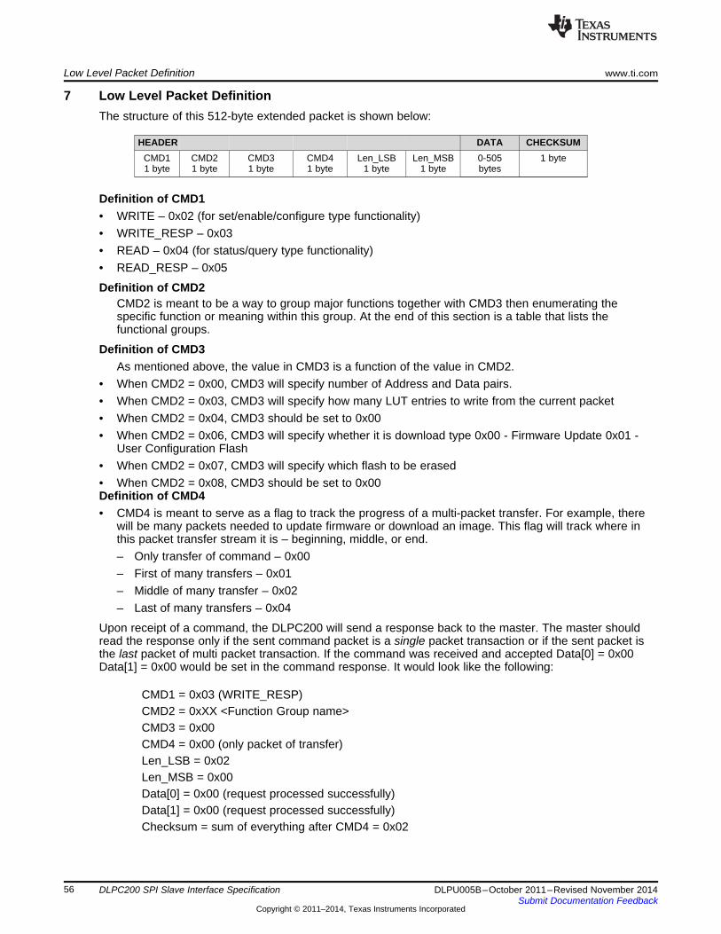
Low Level Packet Definition www.ti.com
7 Low Level Packet DefinitionThe structure of this 512-byte extended packet is shown below:
HEADER DATA CHECKSUMCMD1 CMD2 CMD3 CMD4 Len_LSB Len_MSB 0-505 1 byte1 byte 1 byte 1 byte 1 byte 1 byte 1 byte bytes
Definition of CMD1• WRITE – 0x02 (for set/enable/configure type functionality)• WRITE_RESP – 0x03• READ – 0x04 (for status/query type functionality)• READ_RESP – 0x05
Definition of CMD2CMD2 is meant to be a way to group major functions together with CMD3 then enumerating thespecific function or meaning within this group. At the end of this section is a table that lists thefunctional groups.
Definition of CMD3As mentioned above, the value in CMD3 is a function of the value in CMD2.
• When CMD2 = 0x00, CMD3 will specify number of Address and Data pairs.• When CMD2 = 0x03, CMD3 will specify how many LUT entries to write from the current packet• When CMD2 = 0x04, CMD3 should be set to 0x00• When CMD2 = 0x06, CMD3 will specify whether it is download type 0x00 - Firmware Update 0x01 -
User Configuration Flash• When CMD2 = 0x07, CMD3 will specify which flash to be erased• When CMD2 = 0x08, CMD3 should be set to 0x00Definition of CMD4• CMD4 is meant to serve as a flag to track the progress of a multi-packet transfer. For example, there
will be many packets needed to update firmware or download an image. This flag will track where inthis packet transfer stream it is – beginning, middle, or end.– Only transfer of command – 0x00– First of many transfers – 0x01– Middle of many transfer – 0x02– Last of many transfers – 0x04
Upon receipt of a command, the DLPC200 will send a response back to the master. The master shouldread the response only if the sent command packet is a single packet transaction or if the sent packet isthe last packet of multi packet transaction. If the command was received and accepted Data[0] = 0x00Data[1] = 0x00 would be set in the command response. It would look like the following:
CMD1 = 0x03 (WRITE_RESP)CMD2 = 0xXX <Function Group name>CMD3 = 0x00CMD4 = 0x00 (only packet of transfer)Len_LSB = 0x02Len_MSB = 0x00Data[0] = 0x00 (request processed successfully)Data[1] = 0x00 (request processed successfully)Checksum = sum of everything after CMD4 = 0x02
56 DLPC200 SPI Slave Interface Specification DLPU005B–October 2011–Revised November 2014Submit Documentation Feedback
Copyright © 2011–2014, Texas Instruments Incorporated
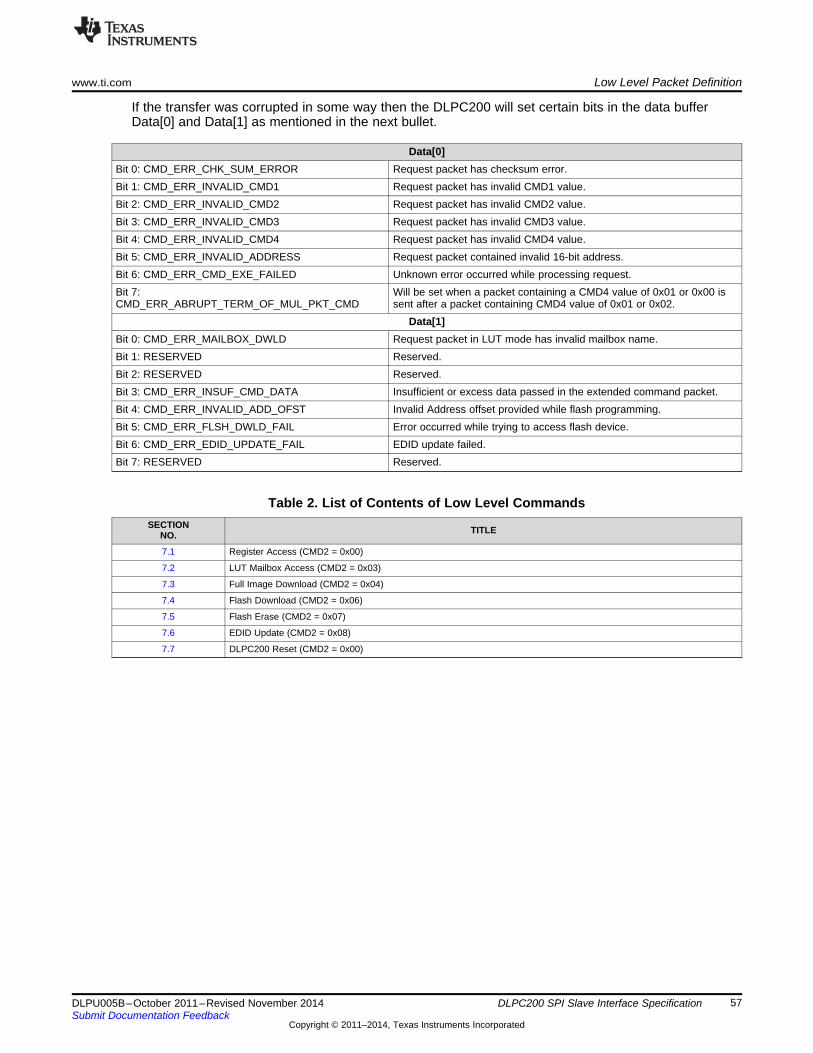
www.ti.com Low Level Packet Definition
If the transfer was corrupted in some way then the DLPC200 will set certain bits in the data bufferData[0] and Data[1] as mentioned in the next bullet.
Data[0]Bit 0: CMD_ERR_CHK_SUM_ERROR Request packet has checksum error.Bit 1: CMD_ERR_INVALID_CMD1 Request packet has invalid CMD1 value.Bit 2: CMD_ERR_INVALID_CMD2 Request packet has invalid CMD2 value.Bit 3: CMD_ERR_INVALID_CMD3 Request packet has invalid CMD3 value.Bit 4: CMD_ERR_INVALID_CMD4 Request packet has invalid CMD4 value.Bit 5: CMD_ERR_INVALID_ADDRESS Request packet contained invalid 16-bit address.Bit 6: CMD_ERR_CMD_EXE_FAILED Unknown error occurred while processing request.Bit 7: Will be set when a packet containing a CMD4 value of 0x01 or 0x00 isCMD_ERR_ABRUPT_TERM_OF_MUL_PKT_CMD sent after a packet containing CMD4 value of 0x01 or 0x02.
Data[1]Bit 0: CMD_ERR_MAILBOX_DWLD Request packet in LUT mode has invalid mailbox name.Bit 1: RESERVED Reserved.Bit 2: RESERVED Reserved.Bit 3: CMD_ERR_INSUF_CMD_DATA Insufficient or excess data passed in the extended command packet.Bit 4: CMD_ERR_INVALID_ADD_OFST Invalid Address offset provided while flash programming.Bit 5: CMD_ERR_FLSH_DWLD_FAIL Error occurred while trying to access flash device.Bit 6: CMD_ERR_EDID_UPDATE_FAIL EDID update failed.Bit 7: RESERVED Reserved.
Table 2. List of Contents of Low Level CommandsSECTION TITLENO.
7.1 Register Access (CMD2 = 0x00)
7.2 LUT Mailbox Access (CMD2 = 0x03)
7.3 Full Image Download (CMD2 = 0x04)
7.4 Flash Download (CMD2 = 0x06)
7.5 Flash Erase (CMD2 = 0x07)
7.6 EDID Update (CMD2 = 0x08)
7.7 DLPC200 Reset (CMD2 = 0x00)
57DLPU005B–October 2011–Revised November 2014 DLPC200 SPI Slave Interface SpecificationSubmit Documentation Feedback
Copyright © 2011–2014, Texas Instruments Incorporated

Low Level Packet Definition www.ti.com
7.1 Register AccessThe Register Access low level control is provided to send the register level configuration information onthe SPI bus. These register configurations are generated with the Project files built under DLPLightCommander® Control GUI software. The output of the project will be in the form of a Batch File. TheDLP LightCommander® GUI software generated Batch File holds the register level configurationinformation of the DLP Control chip. This particular interface function is used in the places where thereference is made to WriteReg in the Batch File.
Example: $L2.5 WriteReg 0xF184 0x1005AA42 entry in the Batch File is an instruction to write the value0x1005AA42 to address 0xF184. This information can be translated as shown below.
PACKET STRUCTURE:CMD1 = 0x02 (WRITE)CMD2 = 0x00 (Register Access Functional Group)CMD3 = 0x01 (One address-data register pair)CMD4 = 0x00 (only packet of transfer)Len_LSB = 0x06Len_MSB = 0x00Data[0] = 0x84 (LSB Address)Data[1] = 0xF1 (LSB+1 Address)Data[2] = 0x42 (LSB Data)Data[3] = 0xAA (LSB+1 Data)Data[4] = 0x05 (LSB+2 Data)Data[5] = 0x10 (LSB+3 Data)Checksum = 0x7C (sum of everything after CMD4)
NOTE: To write to multiple registers within the same packet the SPI master needs to populateCMD3 to the number of address-data pairs desired and would append the subsequentaddress-data information to the Data portion of the packet. Since each address-data pairrequires 6 bytes of storage, the maximum number of register writes that can fit in a singlepacket is 84.
WARNINGSending register addresses with unknown data leads to corruptingDLP Control chip internal state machine and will stop responding.Always stick to the values generated by the DLP LightCommander®
Control GUI software
58 DLPC200 SPI Slave Interface Specification DLPU005B–October 2011–Revised November 2014Submit Documentation Feedback
Copyright © 2011–2014, Texas Instruments Incorporated

www.ti.com Low Level Packet Definition
7.2 LUT/Mailbox AccessThe DLP Control chip contains an internal hardware mailbox. Mailbox data is generated with a Projectbuilt under the DLP LightCommander® Control GUI software. The LUT/Mailbox Access function is used totranslate the mailbox related information from the Batch File into command packets to be send on the SPIbus.
Example: Below is reference from the Batch FIle
Portion of the Batch File containing mailbox information<line 1> $L2.5 DLP_RegIO_BeginLUTdata SEQ_LUT<line 2> $L2.5 WriteReg 0x1111 0x000000f8 # data byte 000000<line 3> $L2.5 WriteReg 0x1111 0x00000008 # data byte 000004<line 4> $L2.5 WriteReg 0x1111 0x00260005 # data byte 000008<line 5> $L2.5 WriteReg 0x1111 0x00080004 # data byte 00000c<line 6> $L2.5 WriteReg 0x1111 0x00080004 # data byte 000010<line 7> $L2.5 WriteReg 0x1111 0x00080004 # data byte 000014<line 8> $L2.5 WriteReg 0x1111 0x00080004 # data byte 000018<line 9> $L2.5 WriteReg 0x1111 0x00080004 # data byte 00001c<line 10> $L2.5 WriteReg 0x1111 0x00080004 # data byte 000020<line 11> $L2.5 WriteReg 0x1111 0x00080004 # data byte 000024<line 12> $L2.5 WriteReg 0x1111 0x00080004 # data byte 000028<line 13> $L2.5 WriteReg 0x1111 0x00080004 # data byte 00002c<line 14> $L2.5 WriteReg 0x1111 0x00080004 # data byte 000030<line 15> $L2.5 WriteReg 0x1111 0x00080004 # data byte 000034<line 16> $L2.5 WriteReg 0x1111 0x00080004 # data byte 000038<line 17> $L2.5 WriteReg 0x1111 0x00080004 # data byte 00003c<line 18> $L2.5 DLP_RegIO_EndLUTdata SEQ_LUT
As per the Batch File syntax and API documentation there are four LUT types• SEQ_LUT• CMT_LUT• RWC_LUT• UMCTDM_LUT
The LUT/Mailbox related portion in the Batch File can be identified with the DLP_RegIO_BeginLUTdataand DLP_RegIO_EndLUTdata terms. The portion between the Begin and End LUT contains the LUT data.The above LUT is translated into the SPI command packet as follows
PACKET STRUCTURE:CMD1 = 0x02 (WRITE)CMD2 = 0x03 (LUT/Mailbox access functional group)CMD3 = 0x10 (Number of LUT data entries in the mailbox. In the above example it is 16)CMD4 = 0x00 (only packet of transfer as ALL LUT entries can be put in single packet)Len_LSB = 0x41 (65 bytes = 1 byte LUT name + 16*4 bytes)Len_MSB = 0x00Data[0] = 0x02 (LUT RWC_LUT = 0x01 <Rarely used>Mailbox name)
SEQ_LUT = 0x02CMT_LUT = 0x06UMCTDM_LUT = 0x08 <Rarely used>
59DLPU005B–October 2011–Revised November 2014 DLPC200 SPI Slave Interface SpecificationSubmit Documentation Feedback
Copyright © 2011–2014, Texas Instruments Incorporated

Low Level Packet Definition www.ti.com
Data[1] = 0xF8 (LSB Data) //1st data entryData[2] = 0x00 (LSB+1 Data)Data[3] = 0x00 (LSB+2 Data)Data[4] = 0x00 (LSB+3 Data)Data[5] = 0x08 (LSB Data) //2nd data entryData[6] = 0x00 (LSB+1 Data)Data[7] = 0x00 (LSB+2 Data)Data[8] = 0x00 (LSB+3 Data)...............Data[61] = 0x04 (LSB Data) // 16th data entryData[62] = 0x00 (LSB+1 Data)Data[63] = 0x08 (LSB+2 Data)Data[64] = 0x00 (LSB+3 Data)Checksum = 0xXX (sum of everything after CMD4)
NOTE: When the LUT size requires more than one packet to transfer then the LUT data entry startsfrom Data[0] position from the second packet onwards.
60 DLPC200 SPI Slave Interface Specification DLPU005B–October 2011–Revised November 2014Submit Documentation Feedback
Copyright © 2011–2014, Texas Instruments Incorporated

www.ti.com Low Level Packet Definition
7.3 Full Image DownloadThe Full Image Download interface is used to download a full image pattern (XGA resolution of 1024x768)over SPI bus. Here, full image corresponds to 1 bit-per-pixel width. So, for a 8 bit-per-pixel image a fullimage download is repeated 8 times for a complete download.
Example:Suppose the user wants to download a 1 bit-per-pixel full image pattern (XGA resolution of1024x768) of alternating 1 pixel wide vertical stripes over SPI. The structure of this pattern would look likethe following:
Figure 4. Alternating Black and White 1 bit-per-pixel image
The number of packets needed to perform the full download is 196 :• The total number of pixels in the image is 1024*768 = 786432.• Due to the 10-bit Memory index and the requirement that the number of bytes with pixel data be a
multiple of 4, the first packet has 500 bytes available for pixel data. With 8 pixels per byte, the firstpacket can store values for 500*8 = 4000 pixels.
• All remaining packets have 504 bytes available for pixel data. With 8 pixels per byte, these packets canstore values for 504*8 = 4032 pixels.
• 1*4000 + 194*4032 = 786208 so, 195 packets not enough storage• 1*4000 + 195*4032 = 790240 M 196 packets is enough storage
The image content is converted into packets as follows:
PACKET-1 STRUCTURE:CMD1 = 0x02 (WRITE)CMD2 = 0x04 (Full Image Pattern Download)CMD3 = 0x00 (RESERVED should always be set to 0x00)CMD4 = 0x01 (First of many packets of transfer)Len_LSB = 0xF6Len_MSB = 0x01Data[0] = 0xE3 (LSB Memory Index) <Valid Range for Memory Index 0 - 959>Data[1] = 0x00 (LSB+1)Data[2] = 0x55 (Pixel values for line 0, pixels 0-7)Data[3] = 0x55 (Pixel values for line 0, pixels 8-15)Data[4] = 0x55 (Pixel values for line 0, pixels 16-23)Data[5] = 0x55 (Pixel values for line 0, pixels 17-31)..........Data[501] = 0x55 (Pixel values for line 3, pixel 920-927)Checksum = 0xXX (sum of everything after CMD4)
61DLPU005B–October 2011–Revised November 2014 DLPC200 SPI Slave Interface SpecificationSubmit Documentation Feedback
Copyright © 2011–2014, Texas Instruments Incorporated

Low Level Packet Definition www.ti.com
PACKET-2 STRUCTURE:CMD1 = 0x02 (WRITE)CMD2 = 0x04 (Full Image Pattern Download)CMD3 = 0x00 (RESERVED should always be set to 0x00)CMD4 = 0x02 (Middle of many packets of transfer)Len_LSB = 0xF8Len_MSB = 0x01Data[0] = 0x55 (Pixel values for line 3, pixels 928-935)Data[1] = 0x55 (Pixel values for line 3, pixels 936-943)Data[2] = 0x55 (Pixel values for line 3, pixels 944-951)Data[3] = 0x55 (Pixel values for line 3, pixels 952-959)..........Data[502] = 0x55 (Pixel values for line 7, pixel ABC to XYZ)Data[503] = 0x55 (Pixel values for line 7, pixel MNO to PQR)Checksum = 0xXX (sum of everything after CMD4)
Packets 3-195 follow same structure as Packet 2.
PACKET-196 STRUCTURE:CMD1 = 0x02 (WRITE)CMD2 = 0x04 (Full Image Pattern Download)CMD3 = 0x00 (RESERVED should always be set to 0x00)CMD4 = 0x04 (last of many packets of transfer)Len_LSB = 0xE0Len_MSB = 0x00Data[0] = 0x55 (Pixel values for line 766, pixels ABC to XYZ)Data[1] = 0x55 (Pixel values for line 766, pixels MNO toPQR)..........Data[222] = 0x55 (Pixel values for line 767, pixel 1008-1015)Data[223] = 0x55 (Pixel values for line 767, pixel 1016-1023)Checksum = 0xXX (sum of everything after CMD4)
NOTE: WriteImageOrderLUTsets how the images are to be displayed on the DMD. When using FullImage Download interface for downloading the image it is important to keep track of MemoryIndex information of image being downloaded. This information helps in callingWriteImageOrderLUT with valid values
NOTE: By default when 1 bit-per-pixel configuration is used the images are stored with MemoryIndex order 0,1,2,....and so forth
62 DLPC200 SPI Slave Interface Specification DLPU005B–October 2011–Revised November 2014Submit Documentation Feedback
Copyright © 2011–2014, Texas Instruments Incorporated

www.ti.com Low Level Packet Definition
NOTE: By default when 8 bit-per-pixel configuration is used each 8 bit image allocated intoconsecutive memory locations as follows:• First 8 bit image will be loaded into Memory Index order 0,1,2,....7 where 0th
location occupied with bi #0 of 8 bit image and 7th location occupied with bit #7of 8 bit image
• Similarly, second 8 bit image will be loaded into Memory Index order 8,9,....15• Repeated as necessary for the number of 8 bit images used in the configuration
63DLPU005B–October 2011–Revised November 2014 DLPC200 SPI Slave Interface SpecificationSubmit Documentation Feedback
Copyright © 2011–2014, Texas Instruments Incorporated

Low Level Packet Definition www.ti.com
7.4 Flash DownloadThe Flash Update interface is used to update the flash devices (Serial Flash and Parallel Flash)connected to DLPC200 over SPI bus. On the Serial Flash the DLPC200 firmware is stored. On theParallel Flash user 'configuration' or Solution is stored. The packet contains the information indicatingwhich flash device it needs to be written to. The first packet contains a four byte flash offset addresslocation from where the flash update starts. The command packet structure allows programming 256 bytesper packet.
7.4.1 Serial Flash DownloadThe typical Serial Flash firmware update binary file size if fixed to 5.0MB or 5242880 byte. It requires atotal of 5242880/256 = 20480 number of packets to complete the download. The Serial Flash (DLPC200firmware) binary content is converted into packets as follows:
PACKET-1 STRUCTURE:CMD1 = 0x02 (WRITE)CMD2 = 0x06 (Flash Update)CMD3 = 0x01 (RESERVED should always be set to 0x01 for Serial Flash update)CMD4 = 0x01 (First of many packets of transfer)Len_LSB = 0x04Len_MSB = 0x01Data[0] = 0x00 (LSB) (Flash Offset Address = 0x00300000)Data[1] = 0x00 (LSB+1 Flash Offset)Data[2] = 0x30 (LSB+2 Flash Offset)Data[3] = 0x00 (LSB+3 Flash Offset)Data[4] = Byte0 (Flash data byte0)Data[5] = Byte1 (Flash data byte1)..........Data[259] = Byte255 (Flash data byte255)Checksum = 0xXX (sum of everything after CMD4)
PACKET-2 STRUCTURE:CMD1 = 0x02 (WRITE)CMD2 = 0x06 (Flash Update)CMD3 = 0x01 (RESERVED should always be set to 0x01 for Serial Flash update)CMD4 = 0x02 (Middle of many packets of transfer)Len_LSB = 0x00Len_MSB = 0x01Data[0] = Byte256 (Flash data byte256)Data[1] = Byte257 (Flash data byte257)Data[2] = Byte258 (Flash data byte258)Data[3] = Byte259 (Flash data byte259)..........Data[254] = Byte510(Flash data byte510)Data[255] = Byte511 (Flash data byte511)Checksum = 0xXX (sum of everything after CMD4)
All intermediate Packets #3 to #20479 follow same structure as Packet 2.
64 DLPC200 SPI Slave Interface Specification DLPU005B–October 2011–Revised November 2014Submit Documentation Feedback
Copyright © 2011–2014, Texas Instruments Incorporated

www.ti.com Low Level Packet Definition
PACKET-20480 LAST STRUCTURE:CMD1 = 0x02 (WRITE)CMD2 = 0x06 (Flash Update)CMD3 = 0x01 (RESERVED should always be set to 0x01 for Serial Flash update)CMD4 = 0x04 (last of many packets of transfer)Len_LSB = 0x00Len_MSB = 0x01Data[0] = ByteXX (Flash data byteXX)Data[1] = ByteXX (Flash data byteXX+1)..........Data[254] = Byte 5242878 (Flash data byte5242878)Data[255] = Byte5242879 (Flash data byte5242879)Checksum = 0xXX (sum of everything after CMD4)
NOTE: Before calling Flash Update it is important to Erase Flash using Flash Erase command.
NOTE: This interface is intended for firmware upgrades in the field. This interface will work onlywhen the Serial Flash has a valid firmware previously loaded and the DLPC200 is able toboot.
NOTE: For blank flash or corrupt flash, there is a different firmware file available that can beprogrammed via a standard flash programmer tool. The firmware size for a blank orcorrupted flash is 8 MB.
7.4.2 Parallel (User Configuration) Flash DownloadParallel Flash stores user configuration data. The User Configuration binary file is built offline using DLPLightCommander GUI control software. The size of the user configuration varies depending on the numberof Solutions in the Project and the number of images loaded with a Non-Real Time Structured Lightsolution:
PACKET-1 STRUCTURE:CMD1 = 0x02 (WRITE)CMD2 = 0x06 (Flash Update)CMD3 = 0x00 (RESERVED should always be set to 0x00 for Parallel Flash update)CMD4 = 0x01 (First of many packets of transfer)Len_LSB = 0x04Len_MSB = 0x01Data[0] = 0xXX (LSB) (Flash Offset Address)Data[1] = 0xXX(LSB+1 Flash Offset)Data[2] = 0xXX (LSB+2 Flash Offset)Data[3] = 0xXX (LSB+3 Flash Offset)Data[4] = Byte0 (Flash data byte0)Data[5] = Byte1 (Flash data byte1)..........
65DLPU005B–October 2011–Revised November 2014 DLPC200 SPI Slave Interface SpecificationSubmit Documentation Feedback
Copyright © 2011–2014, Texas Instruments Incorporated

Low Level Packet Definition www.ti.com
Data[259] = Byte255 (Flash data byte255)Checksum = 0xXX (sum of everything after CMD4)
PACKET-2 STRUCTURE:CMD1 = 0x02 (WRITE)CMD2 = 0x06 (Flash Update)CMD3 = 0x00 (RESERVED should always be set to 0x00 for Parallel Flash update)CMD4 = 0x02 (Middle of many packets of transfer)Len_LSB = 0x00Len_MSB = 0x01Data[0] = Byte256 (Flash data byte256)Data[1] = Byte257 (Flash data byte257)Data[2] = Byte258 (Flash data byte258)Data[3] = Byte259 (Flash data byte259)..........Data[254] = Byte510(Flash data byte510)Data[255] = Byte511 (Flash data byte511)Checksum = 0xXX (sum of everything after CMD4)
All intermediate Packets #3 to #(N-1)th follow same structure as Packet 2.
PACKET-Nth or LAST STRUCTURE:CMD1 = 0x02 (WRITE)CMD2 = 0x06 (Flash Update)CMD3 = 0x00 (RESERVED should always be set to 0x00 for Parallel Flash update)CMD4 = 0x04 (last of many packets of transfer)Len_LSB = 0x00Len_MSB = 0x01Data[0] = ByteXX (Flash data byteXX)Data[1] = ByteXX (Flash data byteXX+1)..........Data[254] = ByteXX or 0xFF (Flash data byte(Last-1) or 0xFF padding)Data[255] = ByteXX or 0xFF (Flash data byte(Last) or 0xFF padding)Checksum = 0xXX (sum of everything after CMD4)
NOTE: If the number of bytes in the Last packet < 256 then Byte padding with 0xFF must be done inthe data packet to make the packet data size = 256.
7.5 Flash EraseThis command packet supports Erasing of Serial and Parallel flash. The command packet requires aBegin and End offset address for the region of the flash to be erased.
7.5.1 Parallel Flash EraseParallel Flash Erase packet structure looks like the following:
66 DLPC200 SPI Slave Interface Specification DLPU005B–October 2011–Revised November 2014Submit Documentation Feedback
Copyright © 2011–2014, Texas Instruments Incorporated

www.ti.com Low Level Packet Definition
PACKET STRUCTURE:CMD1 = 0x02 (WRITE)CMD2 = 0x07 (Flash Erase functional group)CMD3 = 0x10 (Must be set to 0x10 for Parallel Flash Erase)CMD4 = 0x00 (only packet of transfer)Len_LSB = 0x08Len_MSB = 0x00Data[0] = 0xXX (LSB) (Erase Begin Address)Data[1] = 0xXX (LSB+1)Data[2] = 0xXX (LSB+2)Data[3] = 0xXX (LSB+3)Data[4] = 0xYY (LSB) (Erase End Address)Data[5] = 0xYY (LSB+1)Data[6] = 0xYY (LSB+2)Data[7] = 0xYY (LSB+3)Checksum = 0xZZ (sum of everything after CMD4)
NOTE: Depending upon the flash device specification and the requested size/region to be erased,the command response time varies. The SPI master needs to wait until the flash is erase orPoll SLAVE_SPI_ACK pin before excepting the response from DLP Control chip. It issuggested to erase the flash from Begin offset = 0x00000000 and setting End Address offsetfrom the user configuration binary file size information that is generated via DLPLightCommander GUI.
7.5.2 Serial Flash EraseThe Serial Flash or DLPC200 controller firmware size is always fixed. So, the Erase Begin and EndAddress are fixed. Serial Flash Erase packet structure looks like the following:
PACKET STRUCTURE:CMD1 = 0x02 (WRITE)CMD2 = 0x07 (Flash Erase functional group)CMD3 = 0x11 (Must be set to 0x11 for Parallel Flash Erase)CMD4 = 0x00 (only packet of transfer)Len_LSB = 0x08Len_MSB = 0x00Data[0] = 0x00 (LSB) (Erase Begin Address)Data[1] = 0x00 (LSB+1)Data[2] = 0x30 (LSB+2)Data[3] = 0x00 (LSB+3)Data[4] = 0xFF (LSB) (Erase End Address)Data[5] = 0xFF (LSB+1)Data[6] = 0x7F (LSB+2)Data[7] = 0x00 (LSB+3)Checksum = 0xB5 (sum of everything after CMD4)
67DLPU005B–October 2011–Revised November 2014 DLPC200 SPI Slave Interface SpecificationSubmit Documentation Feedback
Copyright © 2011–2014, Texas Instruments Incorporated

Low Level Packet Definition www.ti.com
7.6 EDID UpdateDLP Controller chip support updating the EEPROM to store EDID information. This commands packet isused to send the 128 bytes EDID info to be programmed in the EEPROM. The command packet structurelooks like the following:
PACKET STRUCTURE:CMD1 = 0x02 (WRITE)CMD2 = 0x08 (EDID update functional group)CMD3 = 0x00 (RESERVED has to be set to 0x00)CMD4 = 0x00 (only packet of transfer)Len_LSB = 0x06Len_MSB = 0x00Data[0] = 0x39 (Should always be set for DLP5500 DMD)Data[1] = 0xXX (Offset location from where to start update) valid range <0 - 127>Data[2] = 0xYY (Number of bytes to update from the <offset> location)Data[3] = 0xXX (Data 0)Data[4] = 0xXX (Data 1)Data[5] = 0xXX (Data 2)........Data[N-1] = 0xXX (Data n-1)Data[N] = 0xXX (Data n) where 'n' + 1 = Data[2]Checksum = 0xXX (sum of everything after CMD4)
NOTE: It is preferred to update entire EDID content (that is, from the offset location <0> to <128>)length of data bytes in the payload.
68 DLPC200 SPI Slave Interface Specification DLPU005B–October 2011–Revised November 2014Submit Documentation Feedback
Copyright © 2011–2014, Texas Instruments Incorporated

www.ti.com Low Level Packet Definition
7.7 DLPC200 ResetThis is a special command packet which will cause a reset of DLPC200. The command packet structurelooks like the following:
PACKET STRUCTURE:CMD1 = 0x02 (WRITE)CMD2 = 0x00CMD3 = 0x01CMD4 = 0x00 (only packet of transfer)Len_LSB = 0x06Len_MSB = 0x00Data[0] = 0x80Data[1] = 0x04Data[2] = 0x4AData[3] = 0x00Data[4] = 0x00Data[5] = 0x00Checksum = 0xD4 (sum of everything after CMD4)
NOTE: When Parallel Flash is not used in the reference design or Parallel Flash is Empty/Corrupt,sending this command will create a Black-White Checker Board Test Pattern after the resetcompletion.
69DLPU005B–October 2011–Revised November 2014 DLPC200 SPI Slave Interface SpecificationSubmit Documentation Feedback
Copyright © 2011–2014, Texas Instruments Incorporated

Changes from Original version to Revision A www.ti.com
Changes from Original version to Revision A
Changes from Original (October 2011) to A Revision .................................................................................................... Page
• Overview section is updated with SPI byte transfer timing diagram................................................................ 1• Command/Response protocol explained in other section ........................................................................... 3• New Extended Packet supported - GenerateSWVsync ............................................................................ 52• New Extended Packet supported - ConfigurePWMPeriod ......................................................................... 52• New Extended Packet supported - ConfigurePWMDutyCycle..................................................................... 53• Low Level Packet control definitions added .......................................................................................... 56
Changes from Revision A to Revision B
Changes from A Revision (August 2012) to B Revision ................................................................................................ Page
• Added instructions for how to find the solution address needed in the LoadSolutionFromFlash packet..................... 49• Added calculation of necessary delay time for DisplayPatternAutoStepForSinglePass packet ............................... 51
70 Revision History DLPU005B–October 2011–Revised November 2014Submit Documentation Feedback
Copyright © 2011–2014, Texas Instruments Incorporated

IMPORTANT NOTICE
Texas Instruments Incorporated and its subsidiaries (TI) reserve the right to make corrections, enhancements, improvements and otherchanges to its semiconductor products and services per JESD46, latest issue, and to discontinue any product or service per JESD48, latestissue. Buyers should obtain the latest relevant information before placing orders and should verify that such information is current andcomplete. All semiconductor products (also referred to herein as “components”) are sold subject to TI’s terms and conditions of salesupplied at the time of order acknowledgment.TI warrants performance of its components to the specifications applicable at the time of sale, in accordance with the warranty in TI’s termsand conditions of sale of semiconductor products. Testing and other quality control techniques are used to the extent TI deems necessaryto support this warranty. Except where mandated by applicable law, testing of all parameters of each component is not necessarilyperformed.TI assumes no liability for applications assistance or the design of Buyers’ products. Buyers are responsible for their products andapplications using TI components. To minimize the risks associated with Buyers’ products and applications, Buyers should provideadequate design and operating safeguards.TI does not warrant or represent that any license, either express or implied, is granted under any patent right, copyright, mask work right, orother intellectual property right relating to any combination, machine, or process in which TI components or services are used. Informationpublished by TI regarding third-party products or services does not constitute a license to use such products or services or a warranty orendorsement thereof. Use of such information may require a license from a third party under the patents or other intellectual property of thethird party, or a license from TI under the patents or other intellectual property of TI.Reproduction of significant portions of TI information in TI data books or data sheets is permissible only if reproduction is without alterationand is accompanied by all associated warranties, conditions, limitations, and notices. TI is not responsible or liable for such altereddocumentation. Information of third parties may be subject to additional restrictions.Resale of TI components or services with statements different from or beyond the parameters stated by TI for that component or servicevoids all express and any implied warranties for the associated TI component or service and is an unfair and deceptive business practice.TI is not responsible or liable for any such statements.Buyer acknowledges and agrees that it is solely responsible for compliance with all legal, regulatory and safety-related requirementsconcerning its products, and any use of TI components in its applications, notwithstanding any applications-related information or supportthat may be provided by TI. Buyer represents and agrees that it has all the necessary expertise to create and implement safeguards whichanticipate dangerous consequences of failures, monitor failures and their consequences, lessen the likelihood of failures that might causeharm and take appropriate remedial actions. Buyer will fully indemnify TI and its representatives against any damages arising out of the useof any TI components in safety-critical applications.In some cases, TI components may be promoted specifically to facilitate safety-related applications. With such components, TI’s goal is tohelp enable customers to design and create their own end-product solutions that meet applicable functional safety standards andrequirements. Nonetheless, such components are subject to these terms.No TI components are authorized for use in FDA Class III (or similar life-critical medical equipment) unless authorized officers of the partieshave executed a special agreement specifically governing such use.Only those TI components which TI has specifically designated as military grade or “enhanced plastic” are designed and intended for use inmilitary/aerospace applications or environments. Buyer acknowledges and agrees that any military or aerospace use of TI componentswhich have not been so designated is solely at the Buyer's risk, and that Buyer is solely responsible for compliance with all legal andregulatory requirements in connection with such use.TI has specifically designated certain components as meeting ISO/TS16949 requirements, mainly for automotive use. In any case of use ofnon-designated products, TI will not be responsible for any failure to meet ISO/TS16949.
Products ApplicationsAudio www.ti.com/audio Automotive and Transportation www.ti.com/automotiveAmplifiers amplifier.ti.com Communications and Telecom www.ti.com/communicationsData Converters dataconverter.ti.com Computers and Peripherals www.ti.com/computersDLP® Products www.dlp.com Consumer Electronics www.ti.com/consumer-appsDSP dsp.ti.com Energy and Lighting www.ti.com/energyClocks and Timers www.ti.com/clocks Industrial www.ti.com/industrialInterface interface.ti.com Medical www.ti.com/medicalLogic logic.ti.com Security www.ti.com/securityPower Mgmt power.ti.com Space, Avionics and Defense www.ti.com/space-avionics-defenseMicrocontrollers microcontroller.ti.com Video and Imaging www.ti.com/videoRFID www.ti-rfid.comOMAP Applications Processors www.ti.com/omap TI E2E Community e2e.ti.comWireless Connectivity www.ti.com/wirelessconnectivity
Mailing Address: Texas Instruments, Post Office Box 655303, Dallas, Texas 75265Copyright © 2014, Texas Instruments Incorporated