Embed Size (px)
Citation preview

IM 710105-03E5th Edition
DLM2000 SeriesMixed Signal Oscilloscope

Product RegistrationThank you for purchasing YOKOGAWA products.
YOKOGAWA provides registered users with a variety of information and services.Please allow us to serve you best by completing the product registration form accessible from our homepage.
http://tmi.yokogawa.com/
PIM 103-03E

iIM 710105-01E
ForewordThank you for purchasing the DLM2000 Series Mixed Signal Oscilloscope. This manual contains useful information about the handling precautions and basic operations of the DLM2000. To ensure correct use, please read this manual thoroughly before beginning operation. After reading the manual, keep it in a convenient location for quick reference whenever a question arises during operation. The following four manuals, including this one, are provided as manuals for the DLM2000 series. Read them along with this manual.
Manual Title Manual No. DescriptionDLM2000 SeriesMixed Signal Oscilloscope Features Guide
IM 710105-01E The supplied CD contains the PDF file of this manual. The manual explains the DLM2000 features.
DLM2000 SeriesMixed Signal Oscilloscope User's Manual
IM 710105-02E The supplied CD contains the PDF file of this manual. The manual explains how to operate the DLM2000.
DLM2000 SeriesMixed Signal Oscilloscope Operation Guide
IM 710105-03E This manual. It explains the handling precautions and basic operations of the DLM2000.
DLM2000 SeriesMixed Signal OscilloscopeCommunication InterfaceUser’s Manual
IM 710105-17E The supplied CD contains the PDF file of this manual. The manual explains the DLM2000 communication interface features and instructions on how to use them.
• The contents of this manual are subject to change without prior notice as a result of continuing improvements to the instrument’s performance and functions. The figures given in this manual may differ from the actual screen.
• Every effort has been made in the preparation of this manual to ensure the accuracy of its contents. However, should you have any questions or find any errors, please contact your nearest YOKOGAWA dealer.
• Copying or reproducing all or any part of the contents of this manual without the permission of Yokogawa Electric Corporation is strictly prohibited.
Trademarks• DLM is pending trademark of Yokogawa Electric Corporation.• Microsoft, Internet Explorer, MS-DOS, Windows are either registered trademarks or
trademarks of Microsoft Corporation in the United States and/or other countries.• Adobe, Acrobat, and PostScript are trademarks of Adobe Systems Incorporated.• For purposes of this manual, the TM and ® symbols do not accompany their
respective trademark names or registered trademark names.• Other company and product names are trademarks or registered trademarks of their
respective companies.
Revisions• 1st Edition: November 2008• 2nd Edition: November 2008• 3rd Edition: March 2009• 4th Edition: July 2009• 5th Edition: February 2010
5th Edition : February 2010 (YK)All Rights Reserved, Copyright © 2008 Yokogawa Electric Corporation

ii IM 710105-01E
Checking the Contents of the Package
Unpack the box and check the contents before operating the instrument. If some of the contents are not correct or missing or if there is physical damage, contact the dealer from whom you purchased them.
DLM2000Check that the product that you received is what you ordered. The table below contains information about the available models, suffix codes, and options for your reference.
MODEL SUFFIX Specifications710105 DLM2022 2 channels, 200 MHz710110 DLM2024 4 channels+ 8-bit switchable logic, 200 MHz710115 DLM2032 2 channels, 350 MHz710120 DLM2034 4 channels + 8-bit switchable logic, 350 MHz,710125 DLM2052 2 channels, 500 MHz,710130 DLM2054 4 channels + 8-bit logic, 500 MHz,Power cord -D UL/CSA Standard power cord (Part No.: A1006WD)
[Maximum rated voltage: 125 V]-F VDE Standard Power Cord (Part No.: A1009WD)
[Maximum rated voltage: 250 V]-Q BS Standard Power Cord (Part No.: A1054WD)
[Maximum rated voltage: 250 V]-R AS Standard Power Cord (Part No.: A1024WD)
[Maximum rated voltage: 250 V]-H GB Standard Power Cord (Part No.: A1064WD)
[Maximum rated voltage: 250 V]Language(Menu and Pannel)
-HJ-HE-HC-HG-HF-HK-HL-HS
Japanese+English EnglishChinese+EnglishGerman+EnglishFrench+EnglishKorean+EnglishItalian+EnglishSpanish+English
Options /LN/B5/M1S
/M1
/M2
/P2/P4/C1/C10/C11/C8/G2/G4
/F1/F2/F3/F4/F5/F6
No switchable logic input (4ch model only)Built-in printerMemory expansion to 6.25M/25M/62.5M points(2ch model only)Memory expansion to 6.25M/25M/62.5M points(4ch model only)Memory expansion to 12.5M/62.5M/125M points(4ch model only)Rear panel probe power (2 terminals) (2ch model only)Rear panel probe power (4 terminals) (4ch model only)GP-IB interfaceEthernet interfaceGP-IB + Ethernet interface1.8 GB internal storageUser-defined computation (4ch model only)Power supply analysis function (includes User-defined computation, 4ch model only)UART trigger & analysis (4ch model only)I2C + SPI trigger & analysis (4ch model only)I2C + SPI + UART trigger & analysis (4ch model only)CAN + LIN trigger & analysis (4ch model only)FlexRay trigger & analysis (4ch model only)CAN + LIN + FlexRay trigger & analysis (4ch model only)
No. (Instrument Number)When contacting the dealer from which you purchased the instrument, please give them the instrument number.

iiiIM 710105-01E
Standard AccessoriesThe standard accessories below are supplied with the instrument. Check that all contents are present and that they are undamaged.
Item Model or Part No. Quantity Specifications and NotesPower cord A1006WD
A1009WDA1054WDA1024WDA1064WD
1 UL/CSA StandardVDE StandardBS StandardAS StandardGB Standard
Rubber feet B9989EX 1Roll paper B9988AE 1500-MHz Passive Probe 701939 4 (2) The 710120 and 710130 come with four
probes, and the 710115 and 710125 come with two probes.
200-MHz Passive Probe 701938 4 (2) The 710110 comes with four probes, and the 710105 comes with two probes.
Soft Case B8059GG 1Front cover B8059EP 1Panel sheet See below 1CD-ROM (user's manual) B8059RZ 1 Features Guide and User's Manual
(PDF)Operation Guide IM 710105-03E 1 This manual.
IM 710105-92 1 User's Manual for China
Printer roll paper1
B9988AE 1 roll
Soft caseB8059GG
Front panel protection coverB8059EP
500 MHz Passive Probe 701939 4 probes(710120,710130) 2 probes(710115,710125)
UL/CSA StandardA1006WD
VDE StandardA1009WD
BS StandardA1054WD
AS StandardA1024WD
D F Q R
Power Cord (one of the following power cordsis supplied according to the instrument’s suffix codes)
GB StandardA1064WD
H
Rubber feetB9989EX
1 When using the optional built-in printer (/B5)
A set of manuals· This manual· Other manuals
200 MHz Passive Probe 701938 4 probes(710110) 2 probes(710105)
Panel Sheet B8059GA(Japanese /HJ) B8059GB(Chinese /HC) B8059GC(German /HG) B8059GD(French /HF) B8059GE(Korea /HK) B8059GF(Italian /HL) B8059GJ(Spanish /HS)
Checking the Contents of the Package

iv IM 710105-01E
How to Use the CD-ROM (User's Manuals)The CD-ROM contains PDF files of the following manuals.• DLM2000 Series Mixed Signal Oscilloscope Features Guide IM 710105-01E• DLM2000 Series Mixed Signal Oscilloscope User's Manual IM 710105-02E• DLM2000 Series Mixed Signal Oscilloscope Communication Interface User's Manual IM 710105-17ETo view the above manuals, you need Adobe Reader 5.0 or later.
WARNINGNever play this CD-ROM on an audio CD player. Doing so may cause loss of hearing or speaker damage due to the large sounds that may be produced.
Optional Accessories (Sold Separately)The optional accessories below are available for purchase separately. For information and ordering, contact your nearest YOKOGAWA dealer.
Item Model/ Part No.
Min. Q'ty Specifications
PBA1000 active probe with YOKOGAWA probe interface
701912 1 DC to 1-GHz bandwidth, 100 kΩ, 0.9 pF
PBDH1000 differential probe with YOKOGAWA probe interface
701924 1 DC to 1-GHz bandwidth, 1 MΩ, ±35 V maximum
PBC100 current probe with YOKOGAWA probe interface
701928 1 DC to 100-MHz bandwidth, 30 Arms
PBC050 current probe with YOKOGAWA probe interface
701929 1 DC to 50-MHz bandwidth, 30 Arms
Passive probe 701938 1 DC to 200-MHz bandwidth, 10 MΩ701939 1 DC to 500-MHz bandwidth, 10 MΩ
Logic probe 701988 1 100-MHz toggle frequency, ±40 V maximum701989 1 250-MHz toggle frequency, ±40 V maximum
100:1 high-voltage passive probe 701944 1 DC to 400-MHz bandwidth, 1000 Vrms, 1.2 m in length701945 1 DC to 250-MHz bandwidth, 1000 Vrms, 3 m in length
FET probe * 700939 1 900-MHz bandwidth, 2.5 MΩ, 1.8 pFDifferential probe*
700924 1 DC to 100-MHz bandwidth, ±1400 V maximum700925 1 DC to 15-MHz bandwidth, ±500 V maximum701920 1 DC to 500-MHz bandwidth, ±30 V maximum (common-mode
input)701921 1 DC to 100-MHz bandwidth, ±700 V maximum701922 1 DC to 200-MHz bandwidth, ±60 V maximum (common-mode
input)701926 1 DC to 50-MHz bandwidth, ±5000 V maximum (common-mode
input)Current probe*
701930 1 DC to 10-MHz bandwidth, 150 Arms701931 1 DC to 2-MHz bandwidth, 500 Arms701932 1 DC to 100-MHz bandwidth, 30 Arms701933 1 DC to 50-MHz bandwidth, 30 Arms
Deskew signal source 701935* 1 Approx. 0 to 5 V, approx. -100 to 0 mA, approx. 15 kHz701936 1 Approx. 0 to 5 V, approx. 0 to 100 mA, approx. 0 to 1 A,
approx. 15 kHzGO/NO-GO cable 366973 1 —Mini clip adapter 700971 1 set —PCB adapter 366945 1 set —Solder-in adapter 366946 1 set —Probe stand 1 —
* Used by connecting to a probe power terminal (/P2 or /P4 option) or a probe power supply (701934; sold separately).
Checking the Contents of the Package

vIM 710105-01E
Safety Precautions
This instrument is an IEC protection class I instrument (provided with terminal for protective earth grounding).The general safety precautions described herein must be observed during all phases of operation. If the instrument is used in a manner not specified in this manual, the protection provided by the instrument may be impaired. Yokogawa Electric Corporation assumes no liability for the customer’s failure to comply with these requirements.
The Following Symbols Are Used on This Instrument. Warning: handle with care. Refer to the user’s manual or service manual.
This symbol appears on dangerous locations on the instrument which require
special instructions for proper handling or use. The same symbol appears in the
corresponding place in the manual to identify those instructions.
Protective ground terminal
Functional ground terminal (do not use this terminal as a protective ground
terminal.)
Alternating current
Direct current
ON (power)
OFF (power)

vi IM 710105-01E
Make sure to comply with the precautions below. Not complying might result in injury or death.
WARNINGUse the Correct Power SupplyBefore connecting the power cord, ensure that the source voltage matches the rated supply voltage of the DL9500/DL9700 and that it is within the maximum rated voltage of the provided power cord.
Use the Correct Power Cord and PlugTo prevent the possibility of electric shock or fire, be sure to use the power cord supplied by YOKOGAWA. The main power plug must be plugged into an outlet with a protective earth terminal. Do not invalidate this protection by using an extension cord without protective earth grounding.
Connect the Protective Grounding TerminalMake sure to connect the protective earth to prevent electric shock before turning ON the power. The power cord that comes with the instrument is a three-pin type power cord. Connect the power cord to a properly grounded three-pin outlet.
Do Not Impair the Protective GroundingNever cut off the internal or external protective earth wire or disconnect the wiring of the protective earth terminal. Doing so poses a potential shock hazard.
Do Not Operate with Defective Protective Grounding or FuseDo not operate the instrument if the protective earth or fuse might be defective. Make sure to check them before operation.
Do Not Operate in an Explosive AtmosphereDo not operate the instrument in the presence of flammable liquids or vapors. Operation in such environments constitutes a safety hazard.
Do Not Remove CoversThe cover should be removed by YOKOGAWA’s qualified personnel only. Opening the cover is dangerous, because some areas inside the instrument have high voltages.
Ground the Instrument before Making External ConnectionsSecurely connect the protective grounding before connecting to the item under measurement or an external control unit. If you are going to touch the circuit, make sure to turn OFF the circuit and check that no voltage is present. To prevent the possibility of electric shock or an accident, connect the ground of the probe and input connector to the ground of the item being measured.
See below for operating environment limitations.
CAUTIONThis product is a Class A (for industrial environments) product. Operation of this product in a residential area may cause radio interference in which case the user will be required to correct the interference.
Safety Precautions

viiIM 710105-01E
Waste Electrical and Electronic Equipment
Waste Electrical and Electronic Equipment (WEEE), Directive 2002/96/EC (This directive is only valid in the EU.) This product complies with the WEEE Directive (2002/96/EC) marking
requirement. This marking indicates that you must not discard this electrical/electronic product in domestic household waste.
Product Category With reference to the equipment types in the WEEE directive Annex 1, this
product is classified as a “Monitoring and Control instrumentation” product.
Do not dispose in domestic household waste. When disposing products in the EU, contact your local Yokogawa Europe B. V. office.

viii IM 710105-01E
How to Use This Manual
Structure of the ManualThis manual contains five chapters.
Chapter Title Description1 Component Names and Functions
Introduces the DLM2000 components and their functions, and describes various screens.
2 Before You Start Measuring Describes handling precautions, how to install the DLM2000, how to connect the DLM2000
to a power supply, how to turn the power switch on and off, how to install modules, how to connect probes, and so on.
3 Basic Operations Describes how to use panel keys and the jog shuttle, how to enter characters, how to
initialize the settings to their default values, how to perform auto setup, how to set the clock, and so on.
4 Operating the DLM2000 Using a probe compensation signal as an example, this chapter briefly explains how to
display waveforms, adjust the vertical and horizontal scale, configure triggers, perform cursor measurements, zoom in on waveforms, print and save screen captures, and save waveforms.
5 Specifications Summarizes the DLM2000 specifications in tables.

ixIM 710105-01E
Symbols and Notation Used in This ManualSafety MarkingsThe following markings are used in this manual.
Improper handling or use can lead to injury to the user or damage to the instrument. This symbol appears on the instrument to indicate that the user must refer to the user’s manual for special instructions. The same symbol appears in the corresponding place in the user’s manual to identify those instructions. In the manual, the symbol is used in conjunction with the word “WARNING” or “CAUTION.”
WARNING Calls attention to actions or conditions that could cause serious or fatal injury to the user, and precautions that can be taken to prevent such occurrences.
CAUTION Calls attentions to actions or conditions that could cause light injury to the user or damage to the instrument or user’s data, and precautions that can be taken to prevent such occurrences.
Note Calls attention to information that is important for proper operation of the instrument.
How to Use This Manual

x IM 710105-01E
Contents
Checking the Contents of the Package............................................................................................. iiSafety Precautions ............................................................................................................................vWaste Electrical and Electronic Equipment .................................................................................... viiHow to Use This Manual ................................................................................................................ viii
Chapter 1 Component Names and Functions1.1 Front Panel and Rear Panel ............................................................................................. 1-11.2 Keys and Knobs ............................................................................................................... 1-31.3 Screens ............................................................................................................................ 1-7
Chapter 2 Making Preparations for Measurements2.1 Handling Precautions ....................................................................................................... 2-1
2.2 Installing the Instrument ................................................................................................... 2-3 2.3 Connecting the Power ...................................................................................................... 2-5 2.4 Connecting the Probe ....................................................................................................... 2-8 2.5 Compensating the Probe (Phase Correction) ................................................................ 2-12 2.6 Connecting Logic Probes ............................................................................................... 2-142.7 Attaching the Panel Sheet .............................................................................................. 2-16
Chapter 3 Basic Operations3.1 Key and Jog Shuttle Operations ....................................................................................... 3-13.2 Entering Values and Strings ............................................................................................. 3-33.3 Using USB Keyboards and Mouse Devices ..................................................................... 3-53.4 Synchronizing the Clock ................................................................................................. 3-103.5 Performing Auto Setup ................................................................................................... 3-123.6 Resetting the DLM2000 to Its Factory Default Settings ................................................. 3-143.7 Starting and Stopping Waveform Acquisition ................................................................. 3-153.8 Calibrating the DLM2000 ................................................................................................ 3-163.9 Displaying Help .............................................................................................................. 3-17
Chapter 4 Operating the DLM20004.1 Applying Signals to Measure ............................................................................................ 4-14.2 Changing the Waveform Display Conditions .................................................................... 4-24.3 Changing the Trigger Settings .......................................................................................... 4-44.4 Measuring the Waveform ................................................................................................. 4-64.5 Zooming in on or out from the Waveform ......................................................................... 4-74.6 Printing and Saving the Waveform ................................................................................... 4-8

xiIM 710105-01E
Chapter 5 Specifications5.1 Signal Input Section ......................................................................................................... 5-15.2 Triggering Section ............................................................................................................ 5-35.3 Time Axis .......................................................................................................................... 5-75.4 Display .............................................................................................................................. 5-75.5 Features ........................................................................................................................... 5-75.6 Built-in Printer (/B5 Option) ............................................................................................ 5-155.7 Storage ........................................................................................................................... 5-155.8 USB for Peripherals ........................................................................................................ 5-155.9 Auxiliary I/O Section ....................................................................................................... 5-165.10 Computer Interface ......................................................................................................... 5-175.11 GeneralSpecifications ................................................................................................... 5-185.12 External Dimensions ...................................................................................................... 5-21
Contents
3
2
1
4
5

1-1
Com
ponent Nam
es and Functions
IM 710105-03E
3
2
1
4
5
Chapter 1 Component Names and Functions
1.1 Front Panel and Rear Panel
Front Panel
DLM2054 2.5GS/s 500MHzMIXED SIGNAL OSCILLOSCOPE
FILE
UTILITY
CLEARTRACE
SETUP
MW
MENU
SNAPSHOT
CURSOR MEASURE ANALYSIS MATH/REF DISPLAY ACQUIRE RUN/STOP
VERTICALPOSITION
HORIZONTALPOSITION TRIGGER
FFT
LEVELTRIG’D
PUSHPUSH50%
0 s 50%
EDGE ENHANCED
MODE B TRIG
ACTIONGO / NO-GO
PUSH0DIV
SCALE
PUSHFINE
TIME/DIV
ZOOM
PUSHFINE
ZOOM1 ZOOM2
SEARCH
SERLAL BUS43 LOGIC21
1 / 20 pF 150 Vrms CAT I 50 W 5 Vrms, 10 Vpk
X - Y
AUTO DEFAULT
1
2
3
4
LOGIC
SHIFT
DELAY
ESC
Soft keysUse the soft keys to select items on the soft key menus that appear during configuration.
LCDDescription of the displayed contents → Section 1.3
Jog shuttleUse the jog shuttle to change values and move cursors.
ESC keyUse this key to clear soft key menus and pop-up menus.
USB port for peripheralsUse this port to connect a USB printer, storage device, keyboard, or mouse.
Signal input terminals !en! probe interface terminalConnect probes to these terminals to observe analog signals. → Section 2.4
Functional ground terminalConnect a ground wire to this terminal when correcting a probe phase.
Power switch →Section 2.3
Probe compensation signal output terminal (1 kHz/1 Vp-p)Transmits phase compensation signals for probes.Phase correction procedure→ Section 2.5
Signal input terminal !en! logic signal input terminalConnect a logic probe to this terminal to observe logic signals. This terminal is available on 4-channel models without the /LN option. → Section 2.6
MW
GO / NO-GO 43 LOGIC21
1 / 20 pF 150 Vrms CAT I 50 W 5 Vrms, 10 Vpk
External trigger signal input terminalConnect an external trigger signal input probe to this terminal to take measurements using an external signal.
DLM2022, DLM2032, and DLM2052
Signal input terminals - probe interface terminalConnect probes to these terminals to observe analog signals. → Section 2.4
DLM2024, DLM2034, and DLM2054
SINGLE

1-2 IM 710105-03E
Rear Panel
Power connector → Section 2.3
Main power switch → Section 2.3
USB port for PCsUse this port to connect the DLM2000 to a PC that has a USB port.
GO/NO-GO output connectorThis connector transmits GO/NO-GO result signals.
Ethernet port (optional)Use this port to connect the DLM2000 to a network.
ETHERNET1000BASE-T
LINK
ACT
GP-IB(IEEE488)
PROBE POWER( 12 V DC )
OFF ON
100-240 V AC170 VA MAX 50/60 Hz
GO/NO-GOVIDEO OUT (XGA )
TRIG INTRIG OUT
WARNING
MAIN POWER
Trigger output terminalUse this terminal to transmit trigger signals.
External trigger input terminalUse this terminal to apply external trigger signals.This terminal is located on the front panel on the DLM2022, DLM2032, and DLM2052.
Video signal output terminalUse this terminal to view the DLM2000 display on an external display.
Probe power terminal (/P4 option)Use this terminal to supply power to YOKOGAWA FET probes and current probes. → Section 3.4
USB port for peripheralsUse this port to connect a USB printer, storage device, keyboard, or mouse.
GP-IB connectorUse this connector to communicate with the DLM2000 through the GP-IB interface.
1.1 Front Panel and Rear Panel

1-3
Com
ponent Nam
es and Functions
IM 710105-03E
3
2
1
4
5
1.2 Keys and Knobs
Vertical Axis and ChannelsCH1 to CH4 Keys and LOGIC Key (On 4-channel models)Displays a menu for turning analog signal input channels on and off, for expanding and reducing the vertical axis, and for setting the vertical position, coupling, probe type, offset voltage, bandwidth limit, linear scaling, and waveform labels. Also, press any of these keys to select which channel the SCALE or POSITION knob will control. Channel keys illuminate when the corresponding channel displays are on. And The LED between the SCALE and POSITION knobs illuminates in the color assigned to the selected channel (the color around the CH key).Use the LOGIC key to configure the logic channel. At any given time, you can either use the CH4 analog signal input channel or the logic channel. If you press LOGIC, the logic channel is enabled. If you press CH4, the CH4 analog signal input channel is enabled. The key that corresponds to the enabled channel illuminates.
POSITION KnobUse this knob to change the center position when you change the voltage range. Before you turn this knob, select the source waveform by pressing a key from CH1 to CH4 (or LOGIC). This knob has a push switch. You can press the knob to reset the position to 0.0 divisions. You can also use this knob on the logic channel.
SCALE KnobUse this knob to set the vertical scale. Before you turn this knob, select the target waveform by pressing a key from CH1 to CH4 (or LOGIC). If you change the scale while signal acquisition is stopped, the waveform is expanded or reduced vertically. The setting actually takes effect when you restart signal acquisition.This knob has a push switch. You can press the knob to switch the resolution. If you press the knob so that Fine illuminates, the resolution is set to fine mode.If the target signal is a logic signal, you can expand the waveform by three vertical levels.
Horizontal AxisPOSITION KnobUse this knob to change the center position when you change the time-axis range. This knob has a push switch. You can press the knob to reset the position back to 50%.
DELAY KeyWhen you press the DELAY key, the key illuminates. Then you can set the trigger delay using the POSITION knob. You can reset the trigger delay to its default value (0 s) by pressing the POSITION knob when the DELAY key is illuminated.
TIME/DIV KnobUse this knob to set the time-axis scale. If you change the scale while signal acquisition is stopped, the waveform is expanded or reduced horizontally. If you restart signal acquisition, the DLM2000 acquires signals using the new time-axis scale.
TriggeringEDGE KeyDisplays a menu for setting the edge trigger. When you press this key, the edge trigger is selected, and the key illuminates.
ENHANCED KeyDisplays a menu for setting the enhanced trigger. When you press this key, the enhanced trigger is selected, and the key illuminates.
MODE Key and ACTION GO/NOGO (SHIFT+MODE) KeyDisplays a menu for selecting the trigger mode. Press SHIFT and then press MODE to display an action-on-trigger menu.
VERTICALPOSITION
PUSH0DIV
SCALE
PUSHFINE
1
2
3
4
LOGIC
HORIZONTALPOSITION
PUSH50%0 s
TIME/DIV
TRIGGERLEVEL
TRIG’D
PUSH50%
EDGE ENHANCED
MODE B TRIG
ACTIONGO / NO-GO

1-4 IM 710105-03E
B TRIG KeyUse this key to set trigger combinations with the Edge or Enhanced trigger and to set the trigger B trigger type.LEVEL KnobUse this knob to set the trigger level. This knob has a push switch. You can press the knob to automatically set the trigger level to an appropriate level.
TRIG'D LEDIlluminates when the DLM2000 triggers.
Waveform AcquisitionACQUIRE KeyDisplays a menu for setting the signal acquisition mode.
RUN/STOP KeyStarts and stops signal acquisition according to the trigger mode. The key illuminates while the DLM2000 is acquiring signals.
SINGLE KeyAcquires one waveform. In Average mode, the DLM2000 acquires one waveform that has been obtained by linearly averaging waveforms for the specified number of times.
Zoom, Search, and Serial BusZOOM1 and ZOOM2 KeysDisplays a waveform zoom display menu. When a waveform zoom display is on, the corresponding key illuminates. If ZOOM1 and ZOOM2 are both on, the ZOOM knob controls the magnification of the zoom waveform whose corresponding key is illuminated brightly.
ZOOM KnobWhen a zoom display is on, you can turn this knob to set the magnification of the corresponding horizontal axis. Before turning this knob, press ZOOM1 or ZOOM2 to select the zoom waveform whose magnification you want to control. This knob has a push switch. You can press the knob to switch the resolution. If you press the knob so that Fine illuminates, the resolution is set to fine mode.
SEARCH KeyDisplays a waveform search menu.
SHIFT+SEARCH (SERIAL BUS) KeyPress SHIFT and then press SEARCH to display a serial bus menu.
AnalysisCURSOR KeyDisplays a menu for making cursor measurements.
MEASURE KeyDisplays a menu for automatic measurement of waveform parameters and for statistical processing.
ANALYSIS KeyDisplays a waveform histogram display and an optional power supply analysis menu.
MATH/REF KeyUse this key to configure waveform computation and reference waveforms.
SHIFT+MATH/REF (FFT) KeyPress SHIFT and then press MATH/REF to display an FFT menu.
ACQUIRE RUN/STOPSINGLE
ZOOM
PUSHFINE
ZOOM1 ZOOM2
SEARCH
SERLAL BUS
1.2 Keys and Knobs

1-5
Com
ponent Nam
es and Functions
IM 710105-03E
3
2
1
4
5
DisplayDISPLAY KeyUse this key to configure the display.
SHIFT+DISPLAY (X-Y) KeyPress SHIFT and then press DISPLAY to display an X-Y display menu.
Screen Capture Printing, Data Storage, History Waveforms, and Other FeaturesPRINT KeyUse this key to save and print screen capture data.
SHIFT+PRINT (MENU) KeyDisplays a menu for printing screen captures to the built-in printer or a USB printer or displays a menu for saving screen capture data to a storage medium. An indicator illuminates to show which menu is selected.
FILE KeyDisplays a menu for saving various data to the internal memory and USB memory, loading data that you have saved, and performing other file related tasks.
UTILITY KeyDisplays a menu for calibrating the DLM2000, for LCD back light, for executing self-tests, and for configuring the network, the connection to the PC, the date and time, the menu language, the message language, the LCD back light, the offset cancel, the delay cancel, and the click sound.You can also use this key to display system information (installed options and firmware version).
CLEAR TRACE KeyClears the displayed waveforms. If you execute a clear trace operation during waveform acquisition, the DLM2000 clears all of the history waveforms that it has acquired and restarts waveform acquisition from the first acquisition.
SNAPSHOT KeyRetains the currently displayed waveforms on the screen in white (by default).
HISTORY ( ) KeyDisplays a menu for displaying and searching the history waveforms.
SETUP CURSOR MEASURE ANALYSIS MATH/REF DISPLAY ACQUIRE RUN/STOP
FFT X - Y
AUTO DEFAULTSINGLE
ESC
AUTO SETUP KeyExecutes auto setup, which automatically configures the DLM2000 based on the input signals. The UNDO command, which can be used to revert the settings to their original values, appears in the menu.
DEFAULT SETUP KeyInitializes the DLM2000 settings to their factory default values. The UNDO command, which can be used to revert the settings to their original values, appears in the menu.
1.2 Keys and Knobs
FILE
UTILITY
CLEARTRACE
MENU
SNAPSHOT

1-6 IM 710105-03E
HELP (?) KeyTurns on and off the help window, which explains various features.
SHIFT KeyPress this key once to access the features that are written in purple below each key. The shift key illuminates when the keys are shifted. Press the key again to clear the shifted state.
Function Keys (F1 to F7)Use these keys to select items that appear in the function key menu of the screen.
ESC KeyUse this key to clear the function key menu, close dialog boxes, and return to the menu level above the current one.
Jog ShuttleWhen configuring various settings, use the jog shuttle to set values, move cursors, and select items. Turn the shuttle ring to vary the rate at which values change. The rate is set based on the shuttle ring angle.
RESET ( ) KeyResets the value to its default value.
SET ( ) KeyPress this key to enter the menu item that you selected using the jog shuttle.If there are two items on the jog shuttle setup menu, you can press the key to change the item that the jog shuttle controls.Move the SET key left and right to move the cursor between numeric digits.Move the SET key up and down to increase and decrease a value. You can change the setting on a dialog menu by moving the key up, down, left, and right.
Notes about the Operation of Knobs with Push SwitchesThe following knobs have push switches: SCALE, LEVEL, POSITION (vertical and horizontal), and ZOOM. Push the knobs straight. If you push a knob at an angle, it may not operate properly. If this happens, push the knob straight one more time.
CAUTIONDo not push the knob sideways with strong force. If you do, the knob may break.
1.2 Keys and Knobs

1-7
Com
ponent Nam
es and Functions
IM 710105-03E
3
2
1
4
5
1.3 Screens
Normal Analog Signal Waveform Screen
Display record length
Acquisition mode
Sample rate
Waveform acquisition state
Time/div
Number of waveform acquisitions"Waiting for trig." blinks when the DLM2000 is waiting for a trigger
Trigger level mark
Ground level markThe display is inverted when Invert is set to ON.
Vertical position mark
Channel informationScale and input coupling settings
Trigger information
Trigger positionTrigger point
StoppedRunningPreview: Displayed when changing the Scale, Time/div, and othersettings while
waveform acquisition is stopped.
Logic Signal Waveform Screen (On 4-channel models)
Bit waveformsDisplays waveforms according to the bit
Bus display (bundle)Displays bits 0 to 7 in binary or hexadecimal
Bit informationDisplays each bit state (high or low)

1-8 IM 710105-03E
Screen Displaying Zoom Waveforms
Zoom position of zoom waveform Z1
Z2 Time/div setting
Normal analog waveform area
Zoom waveform area Z1 Time/div setting
Z1 waveform area Z2 waveform area
Normal waveform display record length
Zoom position of zoom waveform Z2Z1 zoom range in the X direction
Z2 zoom range in the X direction
Normal waveform Time/div setting
Z2 display record length
Z1 display record length
Z2Z1
Displays the zoom position relative to the entire waveform when normal analog waveforms are not displayed.
Screen Displaying Analysis Results
Cursor measurement value
Waveform histogram
Statistical trend or histogram display
Normal analog waveform area
Statistics display area
Measured waveform parameter values (statistics)
If the setup menu is not displayed, the setup menu display area shows measured waveform parameter values or cursor measurement values.
1.3 Screens

1-9
Com
ponent Nam
es and Functions
IM 710105-03E
3
2
1
4
5
Hierarchical Display of Setup MenusThe higher-level setup menus are displayed using cascaded tags.
Menu that is one level higher (CH2)Menu that is two levels higher (Ref Level)
1.3 Screens

Making Preparations for M
easurements
2-1IM 710105-03E
3
2
1
4
5
2.1 Handling Precautions
Safety PrecautionsIf you are using this instrument for the first time, make sure to thoroughly read the safety precautions given on pages vi and vii.
Do Not Remove the CaseDo not remove the case from the instrument. Some sections inside the instrument have high voltages and are extremely dangerous. For internal inspections or adjustments, contact your dealer.
Unplug If Abnormal Behavior OccursIf you notice smoke or unusual odors coming from the instrument, immediately turn OFF the power and unplug the power cord. If such an irregularity occurs, contact your dealer.
Do Not Damage the Power CordNothing should be placed on the power cord. The cord should be kept away from any heat sources. When unplugging the power cord from the outlet, never pull by the cord itself. Always hold and pull by the plug. If the power cord is damaged, contact your dealer for replacement. Refer to page iv for the part number when placing an order.
General Handling PrecautionsDo Not Place Objects on Top of the InstrumentNever place other instruments or objects containing water on top of the instrument, otherwise a breakdown may occur.
Do Not Apply Shock to the Input SectionShocks to the input connectors or probes may turn into electrical noise and enter the instrument via the signal lines.
Do Not Damage the LCDSince the LCD screen is very vulnerable and can be easily scratched, do not allow any sharp objects near it. Also it should not be exposed to vibrations and shocks.
Unplug during Extended Non-UseUnplug the power cord from the outlet.
Chapter 2 Making Preparations for Measurements

2-2 IM 710105-03E
When Carrying the InstrumentRemove the power cord and connecting cables. Hold the handle to carry the DLM2000.
CleaningWhen cleaning the case or the operation panel, first remove the power cord from the AC outlet. Then, wipe with a dry, soft, clean cloth Do not use chemical such as benzene or thinner. These can cause discoloring and deformation.
2.1 Handling Precautions

Making Preparations for M
easurements
2-3IM 710105-03E
3
2
1
4
5
2.2 Installing the Instrument
Installation ConditionsInstall the instrument in a place that meets the following conditions.
Flat, Even SurfaceInstall the instrument with the correct orientation on a stable, horizontal surface. The recording quality of the printer may be hindered when the instrument is placed in an unstable or inclined place.
Well-Ventilated LocationInlet holes are located on the left of the instrument. There are also exhaust holes on the rear side. To prevent internal overheating, allow for enough space around the instrument (see the figure below) and do not block the inlet and exhaust holes.
CAUTIONIf you block the inlet holes on the left side or the outlet holes on the rear side of the DLM2000, the DLM2000 will become hot and may break down.
10 cm or more
10 cm or more
5 cm or more
5 cm or more
Including the spaces shown in the drawing above, allow for plenty of space to connect the cables and to open and close the cover of the built-in printer.

2-4 IM 710105-03E
Ambient Temperature and HumidityAmbient temperature 5 - 40°C Ambient humidity 20 to 80% RH when the printer is not used. (No condensation)
35 to 80% RH when using the printer. (No condensation)
Note• To ensure high measurement accuracy, operate the instrument in the 23 ±5°C temperature
range and 55 ±10% RH.• Condensation may occur if the instrument is moved to another place where the ambient
temperature is higher, or if the temperature changes rapidly. In such cases, allow the instrument adjust to the new environment for at least an hour before using the instrument.
Do not install the instrument in the following places.• In direct sunlight or near heat sources.• Where an excessive amount of soot, steam, dust, or corrosive gas is present.• Near strong magnetic field sources. • Near high voltage equipment or power lines.• Where the level of mechanical vibration is high.• On an unstable surface.
Installation positionPlace the instrument in a horizontal position (see the figure below). Rubber stoppers can be attached to the four feet on the bottom of the DLM2000. Four rubber stoppers are included with the DLM2000.
2.2 Installing the Instrument

Making Preparations for M
easurements
2-5IM 710105-03E
3
2
1
4
5
2.3 Connecting the Power
Before Connecting the PowerMake sure that you observe the following points before connecting the power. Failure to do so may cause electric shock or damage to the instrument.
WARNING Beforeconnectingthepowercord,ensurethatthesourcevoltagematchesthe
rated supply voltage of the instrument and that it is within the maximum rated voltage of the provided power cord.
CheckthatboththemainpowerswitchoftheDLM2000isoffbeforeconnectionthe power cord.
Topreventthepossibilityofelectricshockorfire,besuretousethepowercordfor the instrument that was supplied by YOKOGAWA.
Makesuretoperformprotectiveearthgroundingtopreventelectricshock.Connect the power cord to a three-prong power outlet with a protective earth terminal.
Donotuseanextensioncordwithoutaprotectiveearthground.Otherwise,theprotection function will be compromised.
IfanACoutletthatconformstotheaccessorypowercordisunavailableandprotective grounding cannot be furnished, do not use the instrument.
Connecting the Power Cord1. Check that both the main power switch of the DLM2000 is off.
2. Connect the power cord plug to the power connector on the rear panel.
3. Connect the other end of the cord to an outlet that meets the conditions below.Use the three-prong power outlet equipped with a protective earth terminal.
Rated supply voltage* 100 to 240 VACPermitted supply voltage range 90 to 264 VACRated supply voltage frequency 50/60 HzPermitted supply voltage frequency range 48 to 63 HzMaximum power consumption Max. approx. 170 VA* The DLM2000 can use a 100-V or a 200-V system for the power supply. The maximum
rated voltage differs according to the type of power cord. Check that the voltage supplied to the DLM2000 is less than or equal to the maximum rated voltage of the provided power cord (see page iii) before using it.
2-6 IM 710105-03E
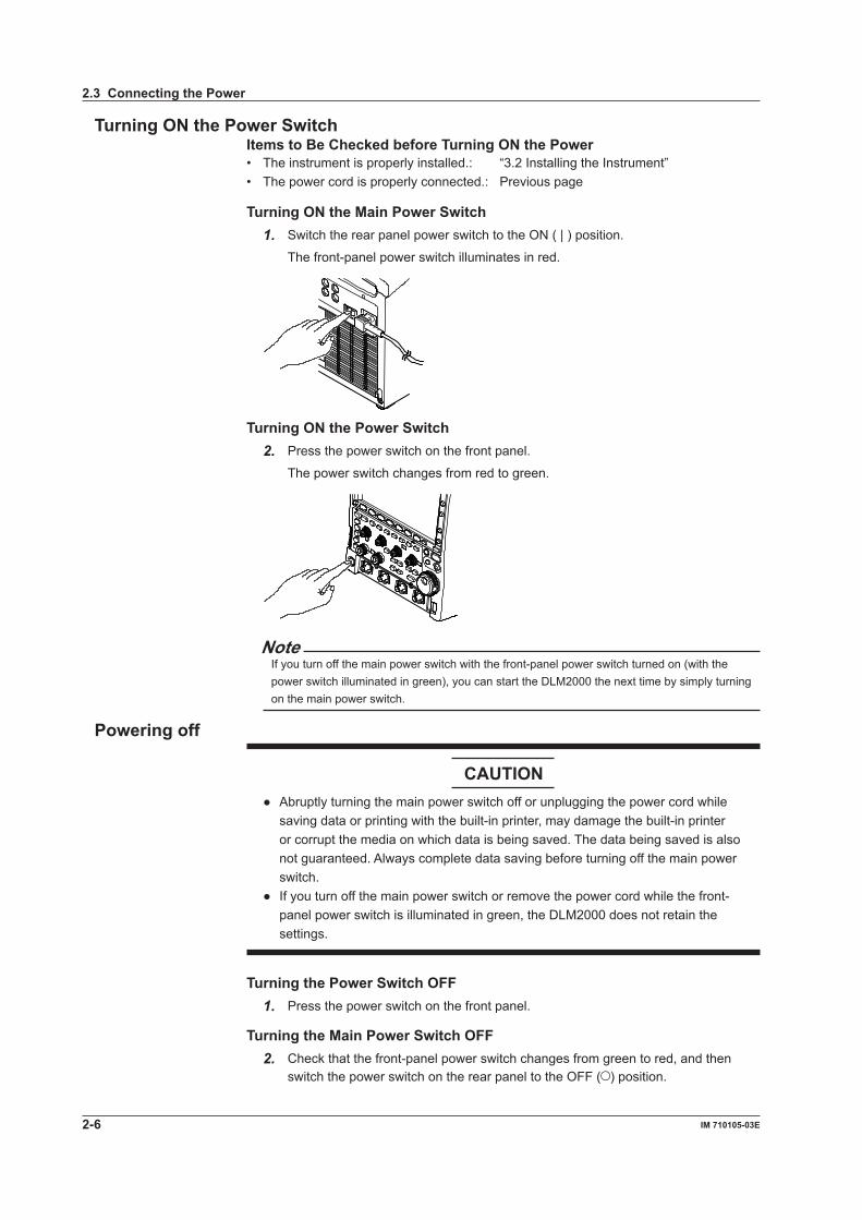
Turning ON the Power SwitchItems to Be Checked before Turning ON the Power• The instrument is properly installed.: “3.2 Installing the Instrument”• The power cord is properly connected.: Previous page
Turning ON the Main Power Switch1. Switch the rear panel power switch to the ON ( | ) position.
The front-panel power switch illuminates in red.
Turning ON the Power Switch2. Press the power switch on the front panel.
The power switch changes from red to green.
NoteIf you turn off the main power switch with the front-panel power switch turned on (with the power switch illuminated in green), you can start the DLM2000 the next time by simply turning on the main power switch.
Powering off
CAUTION Abruptlyturningthemainpowerswitchofforunpluggingthepowercordwhile
saving data or printing with the built-in printer, may damage the built-in printer or corrupt the media on which data is being saved. The data being saved is also not guaranteed. Always complete data saving before turning off the main power switch.
Ifyouturnoffthemainpowerswitchorremovethepowercordwhilethefront-panel power switch is illuminated in green, the DLM2000 does not retain the settings.
Turning the Power Switch OFF1. Press the power switch on the front panel.
Turning the Main Power Switch OFF2. Check that the front-panel power switch changes from green to red, and then
switch the power switch on the rear panel to the OFF ( ) position.
2.3 Connecting the Power

Making Preparations for M
easurements
2-7IM 710105-03E
3
2
1
4
5
Power Up OperationA self-test and calibration start automatically when the power switch is turned ON. If the check results are satisfactory, the normal waveform display screen will appear.
Note• Allow at least 10 seconds before turning ON the power switch after turning it OFF.• If self-test and calibration do not start when the power is turned ON, or if the normal
waveform display screen does not appear, turn OFF the power switch and check the following points.• That the power cord is plugged in properly.• That the correct voltage is coming to the power outlet (see page 2-5).• The settings are initialized (they are returned to factory default settings) by turning on the
power switch while holding down the RESET key. If the instrument still fails to power up when the power switch is turned ON after checking
these points, contact your dealer.• It takes several seconds for the startup screen to appear.
For Taking Accurate Measurements• To ensure accurate measurements, allow the instrument to warm up for at least 30
minutes after turning ON the power switch.• After warm-up is complete, perform calibration. If auto calibration is turned on, auto
calibration is executed when you change the Time/div setting and start waveform acquisition, provided that the specified time has elapsed.
Power Down OperationThe settings just prior to turning OFF the power (or when the power cord is unplugged) are stored. Therefore, the next time the power is turned ON, waveforms are measured using those settings.
Note• If you turn off the rear-panel main power switch while the front-panel power switch is on,
the settings that are used immediately before the power is turned off will not be stored properly. When you turn on the main power switch the next time, the front-panel power switch automatically turns on, and the DLM2000 starts by using the previous settings that were stored properly. If this occurs, a message appears on the screen, but it does not mean that the DLM2000 is broken. When turning the power OFF, turn OFF the power switch of the front panel, and then turn OFF the main power switch of the rear panel.
2.3 Connecting the Power

2-8 IM 710105-03E
2.4 Connecting the Probe
Connect a probe (or measurement input cable such as a BNC cable) to the input terminal on the bottom of the front panel. The input impedance is 1 MΩ ± 1% and approximately 20 pF or 50 Ω ± 1.5%.
WARNING AlwaysturnOFFthepoweroftheobjecttobemeasuredwhenconnectingitto
this instrument. Connecting or disconnecting a measuring lead while the power of the object to be measured is ON is extremely dangerous.
Donotinputexcessivevoltagesthatexceedmaximum input voltage, withstand voltage, or tolerance surge voltage.
Alwaysuseaprotectground(earth)fortheinstrumenttopreventelectricshocks. Avoidcontinuousconnectionsinenvironmentswherethereisthepossibilitythat
tolerance surge voltages can be generated.
CAUTION Theprobeinterfaceterminalislocatedneartheinputterminalonthisinstrument.
When connecting the probe, make sure to prevent an excessive voltage due to static electricity, etc., from being applied to the probe interface terminal, as this may damage it.
Theprobeinterfaceterminalislocatedneartheinputterminalonthisinstrument.Do not short the probe interface terminal.
Themaximuminputvoltagefor1MΩ- input is 150 Vrms when the frequency is 1 kHz or less. Applying a voltage exceeding the value can damage the input section. If the frequency is above 1 kHz, damage may occur even when the voltage is below the value.
Themaximuminputvoltagefor50Ω-inputis5Vrmsand10Vpeak.Applyingavoltage exceeding either of these values can damage the input section.
Precautions to Be Taken When Connecting Cables• When connecting a probe to the instrument for the first time, perform phase
correction of the probe as described in section 2.5, “Compensating the Probe (Phase Correction).” If you do not, frequency characteristics will not be flat, and measurements will not be correct. Perform the phase correction on each channel to which a probe is to be connected.
• Note that if the object being measured is directly connected to the instrument without using a probe, correct measurements may not be possible because of the effect of input impedance on the instrument. Use caution.

Making Preparations for M
easurements
2-9IM 710105-03E
3
2
1
4
5
About ProbesSpecification of standard supplied probe (model 701943), after probe phase compensation
Item Specification ConditionsOverall probe length 701938: 1.5 m
701939: 1.3 m—
Connector type BNC —Input impedance 10 MΩ ±2%
Together with an oscilloscope of input impedance 1 MΩ ±1%
Input capacitance 701938: Approx. 13 pF701939: Approx. 10 pF
Attenuation ratio Not exceeding 10 : 1 ±2%
Bandwidth 701938: DC to 200 MHz(not exceeding –3 dB)701939: DC to 500 MHz(not exceeding –3 dB)
Rise time 701938: 1.75 ns or less (typical*)701939: 700 ps or less (typical*)
Maximum input voltage
600 V (DC+ACpeak) or 424 Vrms When AC does not exceed 100 kHz
* Typical values are typical or mean values. They are not strictly guaranteed.
Precautions to Be Taken When Using Voltage Probes Other Than Those Provided with the Instrument• When measuring a signal including a frequency close to 500 MHz, use a probe with a
frequency range above 500 MHz.• Measurement will only be correct if the attenuation ratio is set properly. Check the
attenuation ration of the probe that you are using and set it properly.
Setting the Probe Attenuation Ratio or Voltage-Current Conversion FactorWhen using a probe not supported by the probe interface connector, set the DLM2000 attenuation ratio or voltage-current conversion factor to match the probe attenuation ratio or voltage-current conversion factor. If this setting is not carried out, correct measurement values will not be displayed.
Connecting a Probe Supported by the Probe Interface Connector• If you connect a probe* supported by the probe interface connector to the DLM2000,
the probe type is automatically recognized, and the attenuation ratio set. Power is supplied to the probe through the probe interface, and therefore it is not necessary to connect the probe power cable to the probe power terminals.
• You can execute automatic zero adjustment on a current probe that is compatible with the probe interface connector.* For a list of compatible probes, see “Optional Accessories” on page v.
2.4 Connecting the Probe

2-10 IM 710105-03E
Connecting FET Probe, Current Probe, Differential Probe, or Deskew Correction Signal Source
If you are using the YOKOGAWA’s FET Probes, Current Probes, Differential Probes, or Deskew Correction Signal Source, use the Probe Power (option) on the DLM2000 rear panel for the power supply. For details on the connection procedure, see the manual that comes with the respective product.
* For a list of probes and signal sources, see “Optional Accessories” on page v.
CAUTIONDo not use the Probe Power Terminal (option) on the DLM2000 rear panel for purposes other than supplying power to the FET Probe, Current Probe, Differential Probe, or Deskew Correction Signal Source. Also, be sure that the total current of the four Probe Power Terminals and the four Probe Interface Terminals does not exceed 1.2 A. Otherwise, the device connected to the Probe Power Terminals or to the DLM2000 may break.
2.4 Connecting the Probe

Making Preparations for M
easurements
2-11IM 710105-03E
3
2
1
4
5
Handling Precautions of the Probe Interface Terminals and Probe Power Terminals
If you are connecting the YOKOGAWA’s FET Probes, Current Probes, Differential Probes, or Deskew Correction Signal Source to the Probe Power Terminals (Option) on the rear panel, be sure that the total current of the four Probe Power Terminals and the four Probe Interface Terminals does not exceed 1.2 A. Otherwise, the DLM2000 operation may become unstable due to the activation of the excessive current protection circuit of the power supply.
• When using current probes (701932/701933), the number of probes is limited, depending on the measured current (the current measured by the current probes). The characteristics of measured current versus current consumption for active probes that can be connected to the DLM2000 are as follows.
701932/701933
-600-500-400-300-200-1000
100200300400500600
-50 -40 -30 -20 -10 0 10 20 30 40 50
701931
-600-500-400-300-200-1000
100200300400500600
-500 -400 -300 -200 -100 0 100 200 300 400 500
701928
-600-500-400-300-200-1000
100200300400500600
-50 -40 -30 -20 -10 0 10 20 30 40 50
701929
-600-500-400-300-200-1000
100200300400500600
-50 -40 -30 -20 -10 0 10 20 30 40 50
Positive power supply, DC inputNegative power supply, DC inputPositive power supply, AC (50 Hz) inputNegative power supply, AC (50 Hz) input
Measured current (A) Measured current (A)
Measured current (A) Measured current (A)
Cur
rent
con
sum
ptio
n (m
A)
Cur
rent
con
sum
ptio
n (m
A)
Cur
rent
con
sum
ptio
n (m
A)
Cur
rent
con
sum
ptio
n (m
A)
Positive power supply, DC inputNegative power supply, DC inputPositive power supply, AC (50 Hz) inputNegative power supply, AC (50 Hz) input
Positive power supply, DC inputNegative power supply, DC inputPositive power supply, AC (50 Hz) inputNegative power supply, AC (50 Hz) input
Positive power supply, DC inputNegative power supply, DC inputPositive power supply, AC (50 Hz) inputNegative power supply, AC (50 Hz) input
• The current consumption of the FET probe (700939) and differential probe (700924, 700925, 701920, 701921, or 701922) should be calculated as a maximum of 125 mA for both negative and positive.
• Calculate the power consumption of the Deskew Correction Signal Source (701935) as 150 mA (positive power supply).
2.4 Connecting the Probe

2-12 IM 710105-03E
2.5 Compensating the Probe (Phase Correction)
Be sure to perform phase correction of the probe first when using a probe to make measurements.
CAUTIONDo not apply external voltage to the signal output terminal for probe compensation adjustment. This may cause damage to the internal circuitry.
Procedure1. Turn ON the power switch.
2. Connect the probe to the input terminal to which the signal is to be applied.
3. Connect the tip of the probe to the signal output terminal for probe compensation adjustment on the front panel of the instrument and to the ground wire to the functional ground terminal.
4. Perform auto setup according to the procedures given in section 3.5, “Performing Auto Setup.”
5. Insert a flat-head screwdriver to the phase adjustment hole and turn the variable capacitor to make the displayed waveform a correct rectangular wave.
Signal output terminal for probe compensation adjustment
Functional ground terminal
Phase adjustment hole

Making Preparations for M
easurements
2-13IM 710105-03E
3
2
1
4
5
ExplanationNecessity of Phase Correction of the ProbeThe probe comes with its phase corrected approximately to match the input capacitance of the relevant oscilloscope. However, there is variance in the input resistance and input capacitance of each input channel of individual oscilloscopes. This results in a mismatch in the voltage divider ratio between low and high frequency signals and causes uneven frequency characterstics.There is a variable capacitor for adjusting the division ratio (trimmer) for high frequency signals on the probe. The phase is corrected by adjusting this trimmer so that even frequency characteristics are obtained.When using the probe for the first time, make sure to perform phase correction.Because the input capacitance varies on each channel, probe compensation is required when the probe is switched from one channel to another.
Phase Compensation SignalThe following square wave signal is output from the signal output terminal for probe compensation adjustment.Frequency: Approx. 1 kHzAmplitude: Approx. 1 V
Differences in the Waveform due to the Phase Correction of the Probe
Correct waveform Over compensated (The gain in the high-frequency region is too high.)
Under compensated(The gain in the high-frequency region is too low.)
2.5 Compensating the Probe (Phase Correction)

2-14 IM 710105-03E
2.6 Connecting Logic Probes
CAUTION Themaximum input voltage for the logic probe(701980, 701981, and 701989)
input is ±40 V (DC+ACpeak) or 28 Vrms. And The maximum input voltage for the logic probe(701988) input is ±42 V (DC+ACpeak) or 29 Vrms. Applying a voltage exceeding either of these values may damage the logic probe or the DLM2000. Damage may occur even if the voltage is below the values specified above. If the frequency is high, the DLM2000 may break at even lower voltages. For information about derating based on frequency, see the respective logic probe user's manual.
The8inputlinesoneachporthaveacommonground.Inaddition,thegroundfor the DLM2000 and the ground for each port are also common. Do not connect inputs that have different common voltages, as doing so may cause damage to the DLM2000, logic probe, or other connected instruments.
MakesuretoturnOFFthepowertotheDLM2000beforeconnectingordisconnecting a logic probe cable(701980 or 701981).
Logic Signal Input PortsConnect the logic probe (701980/701981/701988/701989) to the logic signal input port.
MW
43 LOGIC21
1 / 20 pF 150 Vrms CAT I 50 W 5 Vrms, 10 Vpk
Logic signal input port
About the Logic ProbeThe logic probe (701980/701981/701988/701989) is designed exclusively for the logic signal input ports of the DLM2000. Use the connection lead (accessory) to connect to the point of measurement. Do not alter the connection lead, as it may cause the lead from satisfying the specifications.Each port has 8 lines of logic input terminals. You can set the threshold level from the DLM2000 menu.Recommended probes: 701988/701989 (can be connected even when the DLM2000 is turned on)Compatible probes: 701980/701981 (can be connected when the DLM2000 is turned off)

Making Preparations for M
easurements
2-15IM 710105-03E
3
2
1
4
5
Logic Input Specifications When Used on the DLM2000Item When using the 701989 When using the 701988Maximum toggle frequency1
250 MHz 100 MHz
Number of inputs 8 Same as the 701989Maximum input voltage2 ±40 V(DC + ACpeak) or 28 Vrms ±42 V(DC + ACpeak) or 29 VrmsInput range ±6 V ±40 VMaximum sample rate 1.25 GS/s (interleave mode OFF) Same as the 701989Threshold level ±6 V (resolution: 0.05 V) ±40 V (resolution: 0.05 V)Threshold accuracy1 ±(100 mV + 3% of setting) Same as the 7019891Minimum input voltage1 300 mVp-p 500 mVp-pInput impedance Approx. 100 kΩ, approx. 3 pF(Typical)3 Approx. 1 MΩ, approx. 10
pF(Typical)3
Preset threshold levels CMOS (5 V) = 2.5 V, CMOS (3.3 V) = 1.6 V, CMOS (2.5 V) = 1.2 V, CMOS (1.8 V) = 0.9 V, and ECL = –1.3 V
Same as the 701989
1 Under standard operating conditions (see section 19.11) after warm-up.2 For frequencies up to 1 kHz.3 Typical values are typical or mean values. They are not strictly guaranteed.
2.6 Connecting Logic Probes

2-16 IM 710105-03E
2.7 Attaching the Panel Sheet
Depending on the options that are installed in the DLM2000, attach the supplied front panel sheet if necessary.
ProcedureThe front panel has six panel sheet hooks: two upper, two lower, one below the POSITION knob (HORIZONTAL), and one under the ZOOM knob.Hook the panel sheet onto the two upper hooks.Then, bend the panel sheet slightly, and hook it to the two lower hooks.Hold near the POSITION knob (HORIZONTAL) and ZOOM knob, and insert the panel sheet into the hooks below the knobs.
Panel sheethook

Basic O
perations
3-1IM 710105-03E
3
2
1
4
5
Chapter 3 Basic Operations
3.1 Key and Jog Shuttle Operations
Key OperationsHow to Use Setup Menus That Appear When Keys Are PressedThe operation after you press a key varies depending on the key that you press.
DISPLAY menu
CURSOR menuA B C B
D Jog shuttle setting menuEMODE menu
MATH/REF menuF
G
A: A selection menu appears when you press the soft key. Press the soft key that corresponds to the appropriate setting.B: A related setup menu appears when you press the soft key.C: The selected setting switches each time you press the soft key.D: Displays a dialog box or a keyboard. Use the jog shuttle and the SET key to set values.E: Pressing the soft key selects the item that you can control using the jog shuttle. The jog shuttle setup menu, which appears at the right end of the setup menu,
shows the selected item. Use the SET key to move between digits and set the number.
F: Pressing a key sets the item to the setting that corresponds to that key.G: Selects which item to configure when configuring a feature that consists of
two items that operate with different settings, such as the MATH1 and MATH2 computation features.
How to Display the Setup Menus That Are Written in Purple below the KeysIn the explanations in this manual, "SHIFT+key name (written in purple)" is used to indicate the following operation.
1. Press the SHIFT key. The SHIFT key illuminates to indicate that the keys are shifted.
Now you can select the setup menus written in purple below the keys.
2. Press the key that you want to display the setup menu of.
ESC key operationIf you press the ESC key when a setup menu or available settings are displayed, the screen returns to the menu level above the current one. If you press the ESC key when the highest level menu is displayed, the setup menu disappears. However, the jog shuttle setup menu remains displayed. If you press the ESC key again, the jog shuttle setup menu disappears.

3-2 IM 710105-03E
3.1 Key and Jog Shuttle Operations
Entering Values Using the RESET ( ) and SET ( ) KeysWhen you use the jog shuttle to set a value, the jog shuttle setup menu shows a RESET key mark or a SET key mark.RESET Key MarkIf the RESET key mark is displayed, you can press the RESET key to reset the value to its default value.(The value may not return to its default value depending on the DLM2000 condition.) The default value is displayed next to the RESET key mark.SET Key MarkIf there are two values that you need to set, the SET key mark appears. Press the SET key to select which value you want to set using the jog shuttle. The jog shuttle mark in front of the selected value is enlarged.Like when the RESET key mark is displayed, you can press the RESET key to reset the value to its default value.
Default value
Item under the control of the jog shuttle
RESET key mark SET key mark
How to Enter Values in Setup Dialog Boxes1. Use the keys to display the appropriate setup dialog box.
2. Use the jog shuttle or the SET key ( ) to move the cursor to the appropriate item.
3. Press the SET key ( ). The operation varies depending on the selected item. • A setup menu appears. • A check box is selected or cleared. • The item at the cursor is selected.
How to Clear Setup Dialog BoxesPress the ESC key to clear the active setup dialog box.

Basic O
perations
3-3IM 710105-03E
3
2
1
4
5
3.2 Entering Values and Strings
Entering ValuesUsing Dedicated KnobsYou can use the following dedicated knobs to enter values directly.• POSITION knobs (VERTICAL and HORIZONTAL)• SCALE knob (VERTICAL)• TIME/DIV knob• LEVEL knob (TRIGGER)• ZOOM magnification knob
Using the Jog ShuttleSelect the appropriate item using soft keys, and change the value using the jog shuttle and the SET key. This manual sometimes describes this operation simply as “using the jog shuttle.”
NoteItems that can be set using the jog shuttle are reset to their default values when you press the RESET key.

3-4 IM 710105-03E
3.2 Entering Values and Strings
Entering Character StringsUse the keyboard that appears on the screen to enter file names and comments. Use the jog shuttle and the SET key to control the keyboard and enter characters.
Character insertion position
Confirm the characters that you have enteredSwitch between
uppercase and lowercase
Move the character insertion position
Delete the previous character
Delete all of the characters that you have entered
Select from character strings you entered previously
How to Operate the Keyboard1. After bringing up the keyboard, use the jog shuttle to move the cursor to the
character that you want to enter. You can also move the SET key up, down, left, and right to move the cursor.
2. Press the SET key to enter the selected character.• If a character string is already entered, use the arrow soft keys to move the
cursor to the position you want to insert characters into.• Use the CAPS soft key to switch between uppercase and lowercase.• Use the BS soft key to delete the previous character.• Use the CLEAR soft key to clear all the entered characters.
3. Repeat steps 1 and 2 to enter all of the characters in the string.
Select on the keyboard to display a list of character strings that you have entered previously.
Use the jog shuttle to select a character string and press the SET key to enter the selected character string.
4. Move the cursor to ENTER on the keyboard and press the SET key straight down or press the ENTER soft key to confirm the character string and clear the keyboard.
Note• @ cannot be entered consecutively.• File names are not case-sensitive. Comments are case-sensitive. The following file names
cannot be used due to MS-DOS limitations: AUX, CON, PRN, NUL, CLOCK, COM1 to COM9, and LPT1 to LPT9

Basic O
perations
3-5IM 710105-03E
3
2
1
4
5
3.3 Using USB Keyboards and Mouse Devices
Connecting a USB KeyboardYou can connect a USB keyboard and use it to enter file names, comments, and other items.
Usable KeyboardsThe following keyboards conforming to USB Human Interface Devices (HID) Class Ver. 1.1 can be used.• When the USB keyboard language is English: 104 keyboards• When the USB keyboard language is Japanese: 109 keyboards
Note• Do not connect incompatible keyboards.• The operation of keyboards that have USB hubs or mouse connectors are not guaranteed.• For USB keyboards that have been tested for compatibility, contact your nearest
YOKOGAWA dealer.
USB Port for PeripheralsConnect a USB keyboard to the USB connector for peripherals on the front or rear panel.
Connection ProcedureConnect a USB keyboard directly to the DLM2000 using a USB cable. You can connect or remove the USB cable regardless of whether or not the DLM2000 power switch is turned on (hot-plug support). Connect the type A connector of the USB cable to the DLM2000, and connect the type B connector to the keyboard. When the power switch is on, the keyboard is detected and enabled approximately 6 seconds after it is connected.
Note• Only connect a compatible USB keyboard, mouse, printer, or storage device to the USB
connector for peripherals.• Do not connect multiple keyboards. You can connect one keyboard, one mouse, and one
printer to the DLM2000.• Do not connect and disconnect multiple USB devices repetitively. Allow at least 10 seconds
after you connect or remove one USB device until you connect or remove another USB device.
• Do not remove USB cables during the time from when the DLM2000 is turned on until key operation becomes available (approximately 20 seconds).
Entering File Names, Comments, and Other ItemsWhen a keyboard is displayed on the screen, you can enter file names, comments, and other items using the USB keyboard.
Entering Values from a USB KeyboardYou can use a USB keyboard to enter the values of items with or marks on the menu screens.

3-6 IM 710105-03E
Using a USB MouseYou can connect a USB mouse and use it to perform the same operations that you can perform with the DLM2000 keys. Also, on the menu, you can perform the same kinds of operations that you can perform by pressing a menu item’s soft key or pressing the SET key by pointing to a menu item and clicking on it.
USB Port for PeripheralsConnect a USB mouse to a USB connector for peripherals on the front or rear panel of the DLM2000.
Usable USB Mouse DevicesYou can use mouse devices (with wheels) that are compliant with USB HID Class Version 1.1.
Note• For USB mouse devices that have been tested for compatibility, contact your nearest
YOKOGAWA dealer.• Some settings cannot be configured by a mouse without a wheel.
Connection ProcedureConnect a USB mouse to a DLM2000 USB connector for peripherals. You can connect or disconnect the USB mouse at any time regardless of whether the DLM2000 is on or off (hot-plugging is supported). When the power switch is on, the mouse is detected approximately 6 seconds after it is connected, and the mouse pointer ( ) appears.
Note• Only connect a compatible USB keyboard, mouse, printer, or storage device to the USB
connector for peripherals.• Even though there are two USB connectors for peripherals, do not connect two mouse
devices to the DLM2000.
3.3 Using USB Keyboards and Mouse Devices

Basic O
perations
3-7IM 710105-03E
3
2
1
4
5
Operating the DLM2000 Using a USB Mouse• Operations That Correspond to the Front Panel Keys (Top menu) Displaying the Top Menu Right-click on the display. A menu of the DLM2000 front panel keys appears.
Selecting an Item from the Top Menu Click on the item that you want to select. A setup menu that corresponds to the item
that you selected appears at the bottom of the display. The top menu disappears. To display an item’s submenu, point to the item. To select an item on a submenu, click
on it, just as you would to select an item on the top menu.
Pointer
Top menuRight-click to display the top menu.
SubmenuSubmenus appear for items that have them.
The setup menu of the item that you clicked appears.
Note• The following keys are not displayed in the top menu: ESC, RESET, and SET
• Setup Menu Operations (Same as soft key operations) Selecting a Setup Menu Item Click on the setup menu item that you want to select. If a selection menu appears after you select an item, click on the selection menu item
that you want to choose. If an item such as ON or OFF appears, click on the item to change its setting. For menu items that are usually selected using the job shuttle and the SET key,
clicking on the item that you want to select will confirm your selection and close the dialog box.
Click within this area to display a selection menu.Clicking on the selection menu item that you want to select will confirm your selection.
Click within this area to change the selected item.
3.3 Using USB Keyboards and Mouse Devices

3-8 IM 710105-03E
Clearing the Menu To clear the menu, click outside of it.
• Specifying Values The following description explains how to specify values for menu items that have a
icon next to them.• If there are two icons next to a single menu item, click on the item to select an
item to configure.• To increase a value, rotate the mouse wheel back.• To decrease a value, rotate the mouse wheel forward.• To increase a value, move the pointer above the value so that the pointer becomes
a , and then click the left mouse button.• To decrease a value, move the pointer below the value so that the pointer becomes
a , and then click the left mouse button.• To move the decimal place, point to the left or right of the value you want to set so
that the pointer becomes a or a , and then click the left mouse button. The decimal place will move one place to the right or left each time you click the left
mouse button.
Click within this area to select the item that you want to set.
Change the value by clicking and using the mouse wheel.
• Selecting Check Boxes To select a check box, click on it. To clear a check box, click on it again. Click on the item that you want to select.
Click on the item that you want to select.
NoteTo close a dialog box, click outside of it.
3.3 Using USB Keyboards and Mouse Devices

Basic O
perations
3-9IM 710105-03E
3
2
1
4
5
• Selecting a file, directory, or media drive from the File List window. Click on a file, directory, or media drive to select it. Rotate the mouse wheel to scroll through the file list. To cancel your selection, click outside of the File List window. The File List window will
close when you cancel your selection.
Click on the file, directory, or media drive that you want to select.
Scroll bar
Click on the item that you want to select.
• Setting V/DIV and TIME/DIV Setting V/DIV When the waveform of a channel whose voltage is being measured appears on the
display, move the pointer close to the V/DIV value. The pointer becomes a .
Rotate the mouse wheel forward to increase the V/DIV value, and rotate it back to decrease the value.
Setting TIME/DIV Move the pointer close to the TIME/DIV value. The pointer becomes a . Rotate the mouse wheel forward to increase the TIME/DIV value, and rotate it back to
decrease the value.
Set V/DIV Set TIME/DIV
3.3 Using USB Keyboards and Mouse Devices

3-10 IM 710105-03E
3.4 Synchronizing the Clock
This section explains how to set the DLM2000 clock, which is used to generate timestamps for measured data and files. The DLM2000 is factory shipped with a set date and time. You must set the clock before you start measurements.
Procedure1. Press UTILITY key to display the Utility menu.
System Configuration
2. Press the System Configuration soft key to display the system menu.
3. Press the Date/Time soft key to display the Date/Time Setup dialog box.
Date/Time
Turn the date and time display on or off
Set the date and time display format
Confirm the settings
Set the year, month, day, hour, minute, and second
Set the time difference from Greenwich Mean Time
4. Use the jog shuttle and the SET key to set the date and time.

Basic O
perations
3-11IM 710105-03E
3
2
1
4
5
ExplanationTurning the Display On and Off (Display)Sets whether or not to display the date and time on the DLM2000 screen.
Display Format (Format)You can display the date in one of the following formats. 2008/09/30 (year/numeric month/day) 30/09/2008 (day/numeric month/year) 30-Sep-08 (day-English abbreviation of the month-last two digits of the year) 30 Sep 2008 (day month (English abbreviation) year)
Time Difference from Greenwich Mean Time (Time Diff. GMT)Set the time difference between the region where you are using the DLM2000 and Greenwich Mean Time. Selectable range: -12 hours 00 minutes to 13 hours 00 minutesFor example, Japan standard time is ahead of GMT by 9 hours. In this case, set Hour to 9 and Minute to 00.Checking the Standard TimeUsing one of the methods below, check the standard time of the region where you are using the DLM2000.• Check the Date, Time, Language, Regional Options on your PC.• Check the standard time at the URL on the right.http://www.worldtimeserver.com/
Note• The DLM2000 does not support Daylight Savings Time. To set the time to Daylight Savings
Time, reset the time difference from Greenwich Mean Time.• Date and time settings are backed up using an internal lithium battery. They are retained
even if the power is turned off.• The DLM2000 has leap-year information.
3.4 Synchronizing the Clock

3-12 IM 710105-03E
3.5 Performing Auto Setup
ProcedureExecuting Auto Setup
1. Press AUTO key.
Auto setup is executed, and an Undo item appears.
Undoing Auto Setup2. Press the Undo soft key to revert to the settings that were in effect before
executing auto setup.
ExplanationThe auto setup feature automatically sets the V/div, T/div, trigger level, and other settings to the most suitable values for the input signals.
Center Position after the Execution of Auto SetupThe center position after you execute auto setup will be 0 V.
Source ChannelsAuto setup is performed on all channels except LOGIC.If LOGIC is selected (the LOGIC key is illuminated), auto setup is not performed on CH4.LOGIC waveforms appear using the same settings that were used before you executed auto setup.
Waveforms Displayed before the Execution of Auto SetupData in the acquisition memory is overwritten, and waveforms that were displayed before you executed auto setup are cleared.
Undoing Auto SetupYou can press the Undo soft key to revert to the settings that were in effect before you executed auto setup. You cannot undo auto setup if you switch to a different setup menu or clear the Undo menu using the ESC key.
Signals That Auto Setup Can Be Applied ToFrequency Approx. 50 Hz or higherAbsolute input voltage Signals whose maximum value is at least approximately 20 mV (at 1:1 setting)Type Simple, repeating signals
Note• The auto setup feature may not work properly for signals that include a DC component or
high-frequency components.• To measure serial bus signals, execute auto setup in the appropriate serial bus signal setup
menu.

Basic O
perations
3-13IM 710105-03E
3
2
1
4
5
Settings after the Execution of Auto SetupCH1 to CH4 settingsPosition 0divCoupling DCBW FULLOffset 0VInvert OFFAcquisition settingsRecord Length The same as the value used before you executed auto setup
However, if the record length is such that the DLM2000 cannot acquire waveforms in Single mode, the record length is set to the maximum record length at which the DLM2000 can acquire waveforms repeatedly.
Mode NormalHi Resolution OFFInterleave OFFSampling Mode InterpolationTrigger settingsTrigger type EdgeMode AutoHoldOff 0sDelay 0sPosition 50%Slope RisingCoupling DCHF Rejection OFFNoise Rejection OFFWindow OFFSettings that depend on the input signalCH On/Off On if the DLM2000 detects a voltage of ±20 mV(1:1) or higher and
Off otherwiseV/div Selects the range with the highest sensitivity that does not exceed
±3.5 divisionsTrigger Level CenterTrigger Source The channel with the lowest frequency among the signals whose
amplitude (Max – Min) is at least 1 divisionTime/div The fastest sweep range that allows at least two periods of the
fastest signal among the signals whose amplitude is at least 1 division to be observed. The sweep range must be at least 5 ms/division.
3.5 Performing Auto Setup

3-14 IM 710105-03E
3.6 Resetting the DLM2000 to Its Factory Default Settings
ProcedureResetting the DLM2000 to Its Factory Default Settings
1. Press DEFAULT key.
The DLM2000 is reset to its factory default settings.
An Undo item appears.
Undoing the Reset Operation2. Press the Undo soft key to revert to the previous settings.
ExplanationYou can reset the DLM2000 settings to their factory default values. This feature is useful when you want to cancel all of the settings that you have entered or when you want to redo measurement from scratch.
Settings That Cannot Be Reset to Their Factory Default Values• Date and time settings• Communication settings• Language setting (English or Japanese)
Undoing the Reset OperationIf you reset the settings by mistake, you can press the Undo soft key to revert to the previous settings. However, you cannot undo the reset operation if you switch to a different setup menu or clear the Undo item by pressing the ESC key.
To Reset All Settings to Their Factory Default SettingsWhile holding down the RESET key ( ), turn the power switch on. All settings are reset to their factory default values except the date and time settings (the display on/off setting will be reset) and the setup data stored in internal memory.

Basic O
perations
3-15IM 710105-03E
3
2
1
4
5
3.7 Starting and Stopping Waveform Acquisition
ProcedureStarting or Stopping Waveform Acquisition. Press RUN/STOP key to start or stop waveform acquisition. The key is illuminated while the DLM2000 is acquiring waveforms.
Acquiring Waveforms Using a Single Trigger Press SINGLE key to start waveform acquisition. The key is illuminated while the DLM2000 is acquiring waveforms. The DLM2000 acquires waveforms once when it is triggered and then stops waveform
acquisition. To cancel waveform acquisition, press RUN/STOP key. If you set the record length to a value that allows only one waveform to be acquired,
pressing RUN/STOP key will produce the same result as pressing SINGLE key.
ExplanationWaveform Acquisition and Indicators• When RUN/STOP key or SINGLE key is illuminated, the DLM2000 is acquiring
waveforms. "Running" appears at the upper left of the screen.• When RUN/STOP key and SINGLE key are not illuminated, the waveform acquisition
is stopped. "Stopped" appears at the upper left of the screen.
DLM2000 Operation When the Acquisition Mode Is Set to Averaging• Averaging stops when you stop waveform acquisition.• If you restart waveform acquisition again, averaging starts from the beginning.
RUN and STOP Operations during Accumulation• Accumulation stops when you stop waveform acquisition.• If you restart waveform acquisition, past waveforms are cleared, and accumulation
starts over.
Note• If you start waveform acquisition using RUN/STOP, past data stored in the acquisition
memory is cleared.• You can use the snapshot feature to retain the displayed waveform on the screen. This
feature allows you to retain a waveform on the screen while the DLM2000 continues signal acquisition.

3-16 IM 710105-03E
3.8 Calibrating the DLM2000
Procedure1. Press Utility key.
Calibration
2. Press the Calibration soft key.Executing Calibration
3. Press the Cal Exec soft key to execute calibration.Turning Auto Calibration On or Off
3. Press the Auto Cal soft key to select ON or OFF.
ExplanationCalibrationCalibrates the following items. Execute calibration when you want to make accurate measurements.• Vertical axis ground level and gain• Trigger threshold level• Measured time value for repetitive sampling
NoteCalibration is performed automatically when the power switch is turned on.
Notes about Calibration• Allow the DLM2000 to warm up for at least 30 minutes before you execute calibration.
If you execute calibration immediately after power-on, the calibrated values may drift due to temperature changes or other environmental changes.
• Execute calibration in a stable temperature environment ranging from 5 to 40°C (23 ± 5°C recommended).
• Do not apply signals when calibrating. Calibration may not be executed properly when input signals are being applied to the DLM2000.
Auto Calibration (Auto Cal)Auto calibration is executed when you start signal acquisition if you have changed Time/div and any of the time periods listed below has elapsed since the power was turned on.• 3 minutes• 10 minutes• 30 minutes• One hour and every hour thereafterIf calibration is executed while signals are being applied to the DLM2000, we recommend that you stop signal application and recalibrate the DLM2000.

Basic O
perations
3-17IM 710105-03E
3
2
1
4
5
3.9 Displaying Help
ProcedureDisplaying Help Press the help key (?) to display help. The table of contents and index appear in the left frame, and text appears in the right
frame.
Switching between Frames To switch to the frame that you want to control, move the SET key ( ) left and right.
Moving Cursors and Scrolling To scroll through the screen or to move the cursor in the table of contents or index,
turn the jog shuttle.
Moving to the Link Destination To move to a description that relates to blue text or to move from the table of contents
or index to the corresponding description, move the cursor to the appropriate blue text or item, and press the SET key ( ).
Displaying Panel Key Descriptions With help displayed, press a panel key to display an explanation of the panel key.
Returning to the Previous Screen To return to the previous screen, press the RESET key ( ).
Hiding Help Press help key (?) to clear help.

4-1IM 710105-03E
Operating the D
LM2000
3
2
1
4
5
4.1 Applying Signals to Measure
To help you understand basic oscilloscope operations, this chapter explains how to use the DLM2000 probe compensation signal and perform procedures from displaying waveforms to saving data.
Connecting to the Power SupplyFollow the procedure in section 2.3, "Connecting the Power," and turn the DLM2000 power switch on.
Connecting a ProbeFollow the procedure in section 2.4, "Connecting the Probe" to connect the 701938 or 701939 probe that is supplied with the DLM2000.
Correcting the Probe PhaseFollow the procedure in section 2.5, "Compensating the Probe (Phase Correction)" to correct the probe phase.The waveform of the DLM2000 probe compensation signal appears.
Scale value for each channel Time/div value
NoteBecause the 701938 and 701939 passive probes have probe ID pins, the DLM2000 automatically detects the probe attenuation when you connect one of these probes to a DLM2000 probe terminal.
Chapter 4 Operating the DLM2000

4-2 IM 710105-03E
4.2 Changing the Waveform Display Conditions
This section explains how to change vertical control settings such as the voltage scale and vertical position as well as horizontal control settings such as the time scale.Change these settings while waveform acquisition is in progress.
Changing the Voltage Sensitivity from 500 mV/division to 200 mV/division1. Press the appropriate CH key of the channel whose scale you want to change (CH1
in this example).
2. Use the SCALE knob to change the scale to 200 mV/div. The scale value appears enlarged in the scale display section of the screen.
Press the SCALE knob to set the scale in fine detail (FINE illuminates).
A portion of the waveform can no longer be seen, because the voltage sensitivity has been increased.The new voltage sensitivity
NoteIf you change the scale with the SCALE knob while waveform acquisition is stopped, the waveform is displayed expanded or reduced along the vertical axis.
Decreasing the Vertical Position to View the Entire Waveform1. Use the POSITION knob to change the vertical position to -2.00 div. The value of
the new vertical position appears.
If you press the POSITION knob, the position returns to 0.00 div.
Vertical position value
Ground level also moves.
VERTICALPOSITION
PUSH0DIV
SCALE
PUSHFINE
1
2
3
4
LOGIC
SCALE knob
POSITION knob
VERTICALPOSITION
PUSH0DIV
SCALE
PUSHFINE
1
2
3
4
LOGIC
SCALE knob
POSITION knob

4-3IM 710105-03E
Operating the D
LM2000
3
2
1
4
5
Changing the Time Scale from 200 μs/div to 100 ms/divThe time scale refers to the time per division of the grid.If you increase the time scale when the trigger mode is set to Auto or Auto Level, the DLM2000 switches from update display mode, in which a stationary waveform is updated, to roll mode display, in which waveforms flow from the right to the left of the screen.Roll mode display is useful for observing signals with a long period or signals that change slowly.
1. Use the TIME/DIV knob to set the Time/div setting to 100 ms/div.
Time/div value
NoteIf you change the time/div setting while waveform acquisition is stopped, the waveform is displayed expanded or reduced along the time axis.
Changing the Time Scale from 100 ms/div to 500 μs/divThe DLM2000 switches back from roll mode display to update mode display, and five periods of the waveform appear.
1. Use the TIME/DIV knob to set the Time/div setting to 500 μs/div.
Time/div value
HORIZONTALPOSITION
PUSH50%0 s
TIME/DIV
TIME/DIV knob
HORIZONTALPOSITION
PUSH50%0 s
TIME/DIV
TIME/DIV knob
4.2 Changing the Waveform Display Conditions

4-4 IM 710105-03E
4.3 Changing the Trigger Settings
The trigger settings determine which part of the acquired waveform to display. The main trigger settings are listed below.
Trigger typeTriggers can be classified into edge triggers and enhanced triggers.
Trigger sourceThe trigger source is the signal that is used to check for the trigger condition.
Trigger slopeSlope refers to the signal movement, such as from a low level to a high level (rising slope) or from a high level to a low level (falling slope). When the slope is used as one of the trigger conditions, it is called a trigger slope. An edge refers to a point where the trigger source slope passes through the trigger level.
Trigger levelTrigger level refers to the level that the trigger source must pass through to trigger the DLM2000. With simple triggers such as the edge trigger, the DLM2000 triggers when the trigger source level passes through the specified trigger level.
Trigger modeThe trigger mode that you select specifies the conditions (timing or count) for updating the displayed waveforms. If you execute auto setup, the DLM2000 is set to Auto mode.
Trigger positionWhen you start waveform acquisition, the DLM2000 triggers on the set trigger condition and displays the waveforms stored in the acquisition memory. By moving the trigger position, the ratio of the displayed data before the trigger point (the pre-trigger section) and the data after the trigger point (the post-trigger section) can be changed. The default setting is 50.0% (the screen center).
If you initialize the DLM2000 settings or execute auto setup, the trigger type is set to edge trigger (the trigger is set to CH1). With edge triggers, the DLM2000 triggers on the rising or falling edge of a single input signal.This section explains how to change the trigger slope and trigger position, with the trigger type set to edge trigger.
NoteThe DLM2000 allows you to use trigger combinations, which are combinations of two triggers. If the front-panel B TRIG key is illuminated, a combination trigger is enabled.If you want to trigger the DLM2000 using only an edge trigger or enhanced trigger, check that the B TRIG key is not illuminated. If the key is illuminated, set Combination to OFF using the B TRIG menu.

4-5IM 710105-03E
Operating the D
LM2000
3
2
1
4
5
Changing the Trigger Slope from Rising to Falling1. Press EDGE key.
2. Set Slope to falling ( ).
Trigger point
Triggers on the falling edgeSet the slope to falling
Trigger level
Changing the Trigger Position to 30%Follow the procedure below to move the waveform to the left by 20% (2 divisions) so that you can view more of the post-trigger section of the waveform.
1. Turn the POSITION knob under HORIZONTAL to change the trigger position from 50% to 30%.
Trigger position
Set to 30%
Post-trigger sectionPre-trigger section
Note• Set the trigger position as a percentage from the left end of the screen. The screen center is
50%.• Press the POSITION knob to set the trigger point to 50%.
TRIGGERLEVEL
TRIG’D
PUSH50%
EDGE ENHANCED
MODE B TRIG
ACTIONGO / NO-GO
EDGE key
HORIZONTALPOSITION
PUSH50%0 s
TIME/DIV
POSITION knob
4.3 Changing the Trigger Settings

4-6 IM 710105-03E
4.4 Measuring the Waveform
This section explains how to use vertical cursors to measure the displayed waveform's voltages and its period. Other convenient features such as computation and the automated measurement of waveform parameters can also be used to measure pulse and other periodic waveforms.
Measuring Voltages Using Vertical CursorsThe voltages (Y values) and times (X values) at the cursor positions are displayed at the bottom section of the waveform display frame.
1. Press CURSOR to display cursors.
2. Press the Type soft key to select ΔT.
3. Use the jog shuttle and SET key ( ) to move the cursors.
T1 cursor T2 cursor
T1: T1 cursor X valueT2: T2 cursor X valueΔT: The difference between the X values of T1 cursor and T2 cursor1/ΔT: The inverse of the difference between the X values of T1 cursor and T2 cursorV1: Waveform voltage value at the T1 cursor positionV2: Waveform voltage value at the T2 cursor positionΔV: The difference between V1 and V2
Select the cursor type
Press the SET key ( ) to select T1, T2, or both.User the jog shuttle to move cursors
There are five cursor types.• ΔT cursors: Two ΔT cursors are used to measure time values.• ΔV cursors: Two ΔV cursors are used to measure vertical values.• ΔT&ΔV cursors: Two ΔT cursors and two ΔV cursors are used to measure
time and vertical values.• Marker cursors (Marker): Four marker cursors that move on the waveform are used to
measure waveform values.• Angle cursors (Degree): Two angle cursors are used to measure angles.

4-7IM 710105-03E
Operating the D
LM2000
3
2
1
4
5
4.5 Zooming in on or out from the Waveform
You can expand or reduce a section of the displayed waveform along the time axis.The zoomed waveforms of two locations can be displayed along with the normal waveform. When zoom waveforms are displayed, zoom boxes appear in the normal waveform display frame to indicate the zoom positions.
1. Press ZOOM1 or ZOOM2 key to display a zoom waveform.
2. Use the SET key ( ) to select the item whose zoom position you want to change, and then use the jog shuttle to move the zoom box.
You can change the decimal place of the zoom location value by moving the SET key to the left and right.
3. Use the ZOOM knob to set the magnification.
Press the ZOOM knob to set the magnification in fine detail (FINE illuminates).
The ZOOM knob controls the zoom waveform whose corresponding panel key (ZOOM1 or ZOOM2) is illuminated brightly.
Zoom1 zoom box
Press the SET key ( ) to select Z1 or Z2 (both Z1 and Z2 can also be selected.)Use the jog shuttle to move the zoom position
Zoom2 zoom box
NoteThe ZOOM knob controls the waveforms in the window whose corresponding key, ZOOM1 or ZOOM2, is illuminated.If both keys are illuminated, the ZOOM knob controls the waveforms in the window whose corresponding key is illuminated more brightly.
ZOOM
PUSHFINE
ZOOM1 ZOOM2
ZOOM knob
ZOOM2 keyZOOM1 key

4-8 IM 710105-03E
4.6 Printing and Saving the Waveform
This section explains how to print the displayed waveform on the built-in printer (/B5 option) and how to save measured data or a screen capture to a storage medium.
Printing a Screen Capture on the Built-in PrinterFollow the procedure below to print a screen capture of the waveform. Before you print, follow the procedure in section 15.1 in the User' Manual (on the CD-ROM) to load roll paper into the built-in printer.
1. Press SHIFT key, and then press PRINT(MENU) key.
2. Press the Print To soft key to set the destination to BuiltIn.
3. Press the Mode soft key to set the output format.
HardCopy: Prints a screen capture that includes the setup menu.
Normal: Prints a screen capture, excluding the setup menu.
Long: Prints a screen capture by magnifying it 2 to 10 times along the time axis.
4. Press PRINT (MENU) again.
Set the print destination to BuiltInSet the output mode Set comments

4-9IM 710105-03E
Operating the D
LM2000
3
2
1
4
5
Saving Screen Capture Data to a Storage MediumFollow the procedure below to capture the current screen and save it to a file on a storage medium.
1. Press SHIFT key, and then press PRINT(MENU) key.
2. Press the Print To soft key to set the destination to File.
3. Press the Mode soft key to set the output format.
HardCopy: Saves a screen capture that includes the setup menu.
Normal: Saves a screen capture, excluding the setup menu.
Wide: Saves a screen capture by magnifying it two times along the time axis.
4. Press the Format soft key to set the data format.
5. Press the Color soft key to set the color.
6. Press the Background soft key to set the background to transparent or opaque.
7. Press the File List soft key to set the save destination medium and folder.
8. Press the File Name soft key to set the save destination file name. If you do not set the file name, a sequence number is used for the file name.
Set the print destination to FileSet the output mode
Set the data formatSet the color
Set the backgroundSet the save destination medium
Set the file name
MENU
Illuminates when the destination is File
Illuminates when the destination is not File
4.6 Printing and Saving the Waveform

4-10 IM 710105-03E
Saving Measured Data to a Storage MediumFollow the procedure below to save waveform data displayed on the screen to a storage medium. The vertical, horizontal, and trigger settings for the waveform are also saved in this process.
1. Press File key.
2. Press the Waveform soft key under Save.
3. Press the File List soft key to set the storage destination medium and folder.
4. Press the File Name soft key to set the save destination file name. If you do not set the file name, a sequence number is used for the file name.
5. Press the Data Type soft key to set the data type. The data type that the DLM2000 can load is binary.
6. Press the Trace soft key to set the waveform you want to save.
7. Press the Range soft key to set the range to save.
8. Press the Compression soft key to set the data compression method.
9. Press the Save Waveform soft key to save the waveform.
Set the save destination
Execute the save operationSet the data format
Set the waveform to saveSet the range to save
Set the compression methodSet the file name
4.6 Printing and Saving the Waveform

5-1IM 710105-03E
Specifications
3
2
1
4
5
5.1 Signal Input Section
Analog Signal InputItem SpecificationsNumber of input channels DLM2022(710105), DLM2032(710115), DLM2052(710125): 2 (CH1 and CH2)
DLM2024(710110), DLM2034(710120), DLM2054(710130): 4 (CH1 to CH4)Input coupling settings AC1MΩ,DC1MΩ,DC50Ω,andGNDInput connector BNC connectorInput impedance 1MΩ±1.0%,approx.20pF
50Ω±1.0%(VSWR1.4orlessatDCto500MHz)Selectable voltage sensitivity range
1 MΩ input: 2 mV/div to 10 V/div (in 1-2-5 steps)50 Ω input: 2 mV/div to 500mV/div (in 1-2-5 steps)
Maximum input voltage 1 MΩ input: 150 Vrms CAT I (At 100 kHz and higher, the voltage decreases at 20 dB/decade down to 2.5 Vrms.)
50 Ω input: 5 Vrms or less and 10 Vpeak or lessSelectable maximum DC offset range(When the probe attenuation is set to 1:1)
1 MΩ input2 mV/div to 50 mV/div: ±1 V100 mV/div to 500 mV/div: ±10 V1 V/div to 10 V/div: ±100 V
50 Ω input2 mV/div to 50 mV/div: ±1 V100 mV/div to 500 mV/div: ±5 V
Vertical-axis (voltage-axis) accuracy
DC accuracy1 ±(1.5% of 8 divisions + offset voltage accuracy)Offset voltage accuracy1 2 mV/div to 50 mV/div: ±(1% of set value + 0.2 mV)
100 mV/div to 500 mV/div: ±(1% of set value + 2 mV)1 V/div to 10 V/div: ±(1% of set value + 20 mV)
Frequency Bandwidth(≥–3 dB )1, 2
(When sine wave with amplitude ±3 divp-p equivalent is input)
1 MΩ input (measured from the probe tip when using the supplied 10:1 probe (10:1 conversion))
DLM2022/DLM2024
DLM2032/DLM2034
DLM2052/DLM2054
100 V/div to 100 mV/div: DC to 200 MHz DC to 350 MHz DC to 500 MHz50 mV/div to 20 mV/div: DC to 150 MHz DC to 300 MHz DC to 400 MHz
50 Ω input500 mV/div to 10 mV/div: DC to 200 MHz DC to 350 MHz DC to 500 MHz5 mV/div to 2 mV/div: DC to 150 MHz DC to 300 MHz DC to 400 MHz
–3 dB point for AC coupling 10 Hz or less (1 Hz or less when using the supplied 10:1 probe)Skew between channels(when channels are set to the same conditions)
1 ns or less
Residual noise level3 0.4 mVrms or 0.05 divisions rms, whichever is greater (typical value4)Isolation between channels(when set to the same voltage sensitivity)
Maximum bandwidth: –34 dB (typical value*4)
A/D converter resolution 8 bits (25 LSB/division)12 bits maximum (during high-resolution mode)
Probe attenuation settings Voltage probe: 0.001:1 to 2000:1 (in 1-2-5 steps)Current probe: 0.001A:1V to 2000A:1V (in 1-2-5 steps)
Bandwidth limit For each channel, can be set to FULL, 200 MHz, 100 MHz, 20 MHz, 10 MHz, 5 MHz, 2 MHz, 1 MHz, 500 kHz, 250 kHz, 125 kHz, 62.5 kHz, 32 kHz, 16 kHz, or 8 kHz.Uses IIR and FIR digital filters
Maximum sample rate Real-time sampling mode. Values inside parentheses are for high resolution mode2
When interleave mode is on: 2.5 GS/s (1.25 GS/s)When interleave mode is off: 1.25 GS/s (625 MS/s)Repetitive sampling mode: 125 GS/sInterpolation sampling mode: 125 GS/s
Chapter 5 Specifications

5-2 IM 710105-03E
Item SpecificationsMaximum record length Maximum record length for which repetitive acquisitions are possible
No options: 1.25 M pointsOn models with the /M1 option: 6.25 M pointsOn models with the /M2 option: 12.5 M pointsMaximum record length for which a single acquisition is possible. Values inside parentheses apply when interleave mode is on.No options: 6.25 M points (12.5 M points)On models with the /M1(S) option: 25 M points (62.5 M points)On models with the /M2 option: 62.5 M points (125 M points)
1 Values measured under standard operating conditions (see section 5.11 for details) after a 30-minute warm-up and calibration.2 Values for repeating phenomena. The single-shot frequency bandwidth is from DC to the sampling frequency/2.5 or is the frequency bandwidth of the repeating
phenomena, whichever is less.3 Values when the input section is shorted, the acquisition mode is set to Normal, accumulation is set to off, and the probe
attenuation is set to 1:1.4 Typical values represent typical or average values. They are not strictly warranted.
Logic Signal InputItem SpecificationsUsable probes 701980, 701981, 701988, 701989 (8-bit input)Number of inputs 8 Nondestructive maximum input voltage
701980, 701981, 701989: ±40 V (DC + ACpeak) or 28 Vrms701988: ±42 V (DC + ACpeak) or 29 VrmsFor information about derating based on frequency, see the respective logic probe user's manual.When using the 701980
When using the 701981 When using the 701988
When using the 701989
Input range ±40 V ±10 V ±40 V Threshold level ± 6 VMinimum input voltage 500 mVp-p 500 mVp-p 500 mVp-p 300 mVp-pMaximum toggle frequency1 100 MHz 250 MHz 100 MHz 250 MHzInput impedance (typical value*3)
1 MΩ/approx. 10 pF 10 kΩ/approx. 9pF 1 MΩ/approx. 10 pF Approx. 100 kΩ/approx. 3 pF
Variable threshold level range
±40 V ±10 V ±40 V ±6 V
Threshold level setting Same value for all 8 bits
Same value for all 8 bits
Same value for all 8 bits
Different values for each of the 8 bits
Threshold level resolution 0.1 V 0.1 V 0.05 V 0.05 VThreshold level accuracy1 ±(0.1 V + 3% of setting) ±(0.1 V + 3% of setting) ±(0.1 V + 3% of
setting)±(0.1 V + 3% of setting)
Hysteresis voltage (typical value3)
80 mV 50 mV 100 mV When noise rejection is off: 100 mVWhen noise rejection is on: 250 mV
Minimum pulse width 5 ns 2 ns 5 ns 2 nsMaximum sample rate Real-time sampling mode. Values inside parentheses are for high resolution mode2
When interleave mode is on: Unable to acquire logic waveformsWhen interleave mode is off: 1.25 GS/s (625 MS/s)Repetitive sampling mode: 125 GS/sInterpolation sampling mode: 125 GS/s (Pulse interpolation for logic waveforms)
Maximum record length Maximum record length for which repetitive acquisitions are possibleNo options: 1.25 M pointsOn models with the /M1 option: 6.25 M pointsOn models with the /M2 option: 12.5 M pointsMaximum record length for which a single acquisition is possible. No options: 6.25 M points On models with the /M1 option: 25 M points On models with the /M2 option: 62.5 M points
1 Under standard operating conditions (see section 5.11 for details) after a 30-minute warm-up.2 Resolution only improves for analog waveforms.3 Typical values represent typical or average values. They are not strictly warranted.
5.1 Signal Input Section

5-3IM 710105-03E
Specifications
3
2
1
4
5
5.2 Triggering Section
Item SpecificationsTrigger modes Auto, Auto Level, Normal, Single, N Single
The DLM2000 measures in Single mode when you start acquisition by pressing the SINGLE key or when you start acquisition by pressing the RUN/STOP key when the record length setting only allows for single acquisition.
Trigger sources CH1 to CH41 Signals received through input terminalsLINE: The connected commercial power supply signal (only Edge trigger can be
used)EXT: The signal received through the TRIG IN terminal (EXT. terminal on the
DLM2022, DLM2032, and DLM2052)Logic bits 0 to 72 Signals received through the logic signal input port terminals
Trigger coupling CH1 to CH41: DC/ACEXT: DC
HF rejection Trigger source bandwidth limit can be specified separately for CH1 to CH4.1
OFF: No bandwidth limit15 kHz: DC to approximately 15 kHz20 MHz : DC to approximately 20 MHz
Noise rejection Noise rejection can be turned on or off (trigger level hysteresis can be selected) for CH1 to CH4*1 separately. Noise rejection cannot be specified on channels set to TV trigger.OFF: Approximately 0.3 divisions* of hysteresisON: Approximately 1.0 divisions* of hysteresis
Selectable trigger level range CH1 to CH41: ±4 divisions from the screen centerEXT: ±2 V (DLM2024, DLM2034, DLM2054)
±1 V (±1 V range on the DLM2022, DLM2032, DLM2052)±10 V (±10 V range on the DLM2022, DLM2032, DLM2052)
Trigger level resolution CH1 to CH41: 0.01 divisions (0.1 divisions for TV triggers)EXT: 5 mV (DLM2024, DLM2034, DLM2054)
5 mV (±1 V range on the DLM2022, DLM2032, DLM2052)50 mV (±10 V range on the DLM2022, DLM2032, DLM2052)
Trigger level accuracy CH1 to CH4:1, 3 ±(0.2 divisions + 10% of the trigger level)EXT:*4 ±(50 mV + 10% of the trigger level) for DLM2024, DLM2034, DLM2054
±(50 mV + 10% of the trigger level) for the ±1 V range on the DLM2022, DLM2032, DLM2052±(500 mV + 10% of the trigger level) for the ±10 V range on the DLM2022, DLM2032, DLM2052
Window comparator setting Window comparator can be turned on or off for CH1 to CH41 separatelyOFF Normal comparator
Edge polarities: Rise and Fall. Qualifications: H, L, and X.ON Window comparator
Edge polarities: Enter and Exit. Qualifications: IN, OUT, and X.Selectable window trigger level range
CH1 to CH41 separatelyCenter: ±4 divisions from the screen centerWidth: ±4 divisions around the center
Window trigger level accuracy
The following trigger level accuracy applies to the upper and lower limits of the window that are specified using the Center and Width settings. The upper and lower limits are set separately for CH1 to CH4.1 ±(0.2 divisions + 10% of the trigger level)However, the accuracy does not apply to an upper or lower limit that falls outside ±4 divisions from the screen center.
External trigger probe attenuation setting
1:1, 10:1
Trigger sensitivity CH1 to CH4:1 1 divP-P DC to the maximum bandwidth (with noise rejection set to off)
EXT: 100 mVP-P DC to 100 MHz (DLM2024, DLM2034, DLM2054)100 mVP-P DC to 100 MHz (±1 V range on the DLM2022, DLM2032,
DLM2052)1 divP-P DC to 100 MHz (±10 V range on the DLM2022, DLM2032,
DLM2052)Trigger position Can be set as a percentage of the display record length in 0.1% steps

5-4 IM 710105-03E
Item SpecificationsSelectable trigger delay range
-(Time length of the post-trigger section) to 10 s
Selectable hold-off time range
20 ns to 10 s
Trigger type (A trigger)Edge: Triggers on the edge of a single trigger source
The source can be set to a signal from CH1 to CH4,1 from logic bits 0 to 7,*2 EXT, or LINE.
Edge OR: Triggers when any of the edge trigger conditions of multiple trigger sources is metSources can be set to channels from CH1 to CH4.1
Edge Qualified: Triggers on the edge of a single trigger source while qualifications are metThe source can be set to a signal from CH1 to CH4,1 from logic bits 0 to 7,2 or EXT. Qualifications can be specified for CH1 to CH41 and for logic bits 0 to 7.2
State: Triggers when the state condition changes from met to not met or from not met to metState conditions can be applied to all sources using AND or OR.A clock channel can be specified that is used to determine the met or not met state condition. No clock can also be selected.The source and state clock can be set to a signal from CH1 to CH41 or from logic bits 0 to 7.2
Pulse Width: Triggers on the width of a single trigger sourceThe source can be set to a signal from CH1 to CH4,1 from logic bits 0 to 7,*2 or EXT.more than: Triggers when the time length during which the condition
is met is longer than Time1, and the condition changes to not metTime1: 4 ns to 10 s in 2-ns steps
less than: Triggers when the time length during which the condition is met is shorter than Time1, and the condition changes to not metTime1: 6 ns to 10 s in 2-ns steps
between: Triggers when the time length during which the condition is met is longer than Time1 but shorter than Time2 and the condition changes to not metTime1: 4 ns to (10 s – 4 ns) in 2-ns stepsTime2: 8 ns to 10 s in 2-ns stepsMinimum spacing between Time1 and Time2: 4 ns
out of range: Triggers when the time length during which the condition is met is shorter than Time1 or longer than Time2 and the condition changes to not metTime1: 6 ns to (10 s – 4 ns) in 2-ns stepsTime2: 8 ns to 10 s in 2-ns stepsMinimum spacing between Time1 and Time2: 4 ns (2 ns only when Time1 = 6 ns and Time2 = 8 ns)
time out Triggers when the time length during which the condition is met exceeds Time1.Time1: 4 ns to 10 s in 2-ns steps
Time accuracy:4
±(0.5% of setting + 2 ns)
Minimum time detection width:
2 ns (typical value*5)
State Width Triggers on the time-duration for which the state condition is met or not metFor a description of the state conditions, see "State Pattern."The source and state clock can be set to a signal from CH1 to CH41 or from logic bits 0 to 7.2For details on the time settings, see "Pulse Width."
5.2 Triggering Section

5-5IM 710105-03E
Specifications
3
2
1
4
5
Item SpecificationsFlexRay6 Triggers on a FlexRay bus signal
The source can be set to a signal from CH1 to CH4.Modes: Frame Start, Error, ID/Data, ID ORBitRates: 2.5 M, 5 M, 10 MbpsBus channels: A, B
CAN6 Triggers on a CAN (Controller Area Network) bus signalThe source can be set to a signal from CH1 to CH4.Modes: SOF, Error, ID/Data, ID ORBitRates: 1 M, 500 k, 250 k, 125 k, 83.3 k, 33.3 kbps, User DefineFor User Define, you can set a value from 1 M to 100 kbps in 0.1-kbps steps.
LIN6 Triggers on a LIN (Local Interconnect Network) bus signalThe source can be set to a signal from CH1 to CH4.Modes: Break Synch, Error, ID/Data, ID ORBitRates: 1200, 2400, 4800, 9600, 19200 bps, User DefineFor User Define, you can set a value from 1 k to 20 kbps in 0.01-kbps steps.
UART6 Triggers on a UART (RS232) signalThe source can be set to a signal from CH1 to CH4 or from logic bits 0 to 7.2Modes: Every Data, Error, DataFormats: 8-bit data (no parity bit), 7-bit data + parity bit, 8-bit data + parity bitBitRates: 1200, 2400, 4800, 9600, 19200 bps, 38400 bps, 57600 bps, 115200 bps, User DefineFor User Define, you can set a value from 1 k to 1000 kbps in 0.1-kbps steps.
I2C6 Triggers on an I2C bus signal.The source can be set to a signal from CH1 to CH4 or from logic bits 0 to 7.2Modes: Every Start, Adr Data, NON ACK, General Call, Start byte, HS Mode
SPI6 Triggers on an SPI (Serial Peripheral Interface) bus signalThe source can be set to a signal from CH1 to CH4 or from logic bits 0 to 7.2Modes: 3wire, 4wire
User Define Triggers on a general-purpose serial communication signalThe source can be set to a channel from CH1 to CH4.1Data channel, chip select channel, clock channel, and latch channel can be specified.Bit rate: 1 k to 200 Mbps (with clock) 1 k to 49.5 Mbps (without clock)Bit length: 1 to 128 bits
TV Triggers on the specified field number, line number, or polarity in video signals of various broadcasting formats.The source can be set to a channel from CH1 to CH4.1Mode: NTSC: Triggers on an NTSC (525/60/2) signal PAL: Triggers on a PAL (625/50/2) signal SDTV: Triggers on an SDTV (480/60p) signal HDTV: Triggers on the following HDTV signals 1080/60p, 1080/60i, 1080/50ip, 1080/25p, 1080/24p, 1080/24sF, 720/60 USER Def: You can trigger on any TV signal by selecting standard or high definition, setting the H sync period, and setting the sync guard. Sync guard can be set to a value from 60 to 90% of the H sync value in 1% steps.Polarity: Pos, NegHF Rej: NTSC/PAL: 300 kHz (fixed) SDTV/HDTV: OFF (fixed) User Def: Off or 300 kHzLine: 5 to 1054 (NTSC), 2 to 1251 (PAL), 8 to 2251 (SDTV), 2 to 2251 (HDTV), 2 to 2251 (USER), ALLField: 1, 2, XFrame Skip: 1, 2, 4, 8
5.2 Triggering Section

5-6 IM 710105-03E
Item SpecificationsAB trigger Able to trigger on the combination of triggers A and B
Some trigger types cannot be specified depending on the AB trigger type as shown below.(see Trigger Type (A trigger))
OFF: Triggers only on the trigger A conditions (the trigger B conditions are not used).
A Delay B: After the trigger A conditions are met and the specified amount of time elapses, the DLM2000 triggers when the trigger B conditions are met.Trigger B cannot be set to Edge OR, Width, or TV.Delay value: 10 ns to 10 s
A to B(N): After the trigger A conditions are met, the DLM2000 triggers when the trigger B conditions are met N times.Trigger B cannot be set to Edge OR, Width, or TV.N value: 1 to 109
Dual Bus: The DLM2000 triggers when the serial bus trigger A or B conditions are met.
1 CH1 and CH2 on the DLM2022, DLM2032, and DLM2052.2 Logic only available on the DLM2024, DLM2034, and DLM2054.3 Values measured under standard operating conditions (see section 5.11 for details) after a 30-minute warm-up and calibration.4 Values measured under standard operating conditions (see section 5.11 for details) after a 30-minute warm-up.5 Typical values represent typical or average values. They are not strictly warranted.6 FlexRay, CAN, LIN, UART, I2C, and SPI are options. They cannot be used on the DLM2022, DLM2032, and DLM2052.
5.2 Triggering Section

5-7IM 710105-03E
Specifications
3
2
1
4
5
5.3 Time Axis
Item SpecificationsSelectable time scale range 1 ns/division to 500 s/divisionTimebase accuracy* ±0.002%Time measurement accuracy*
±(0.002% + 50 ps + 1 sample period)
* Values measured under standard operating conditions (see section 5.11 for details) after a 30-minute warm-up.
5.4 Display
Item SpecificationsDisplay 8.4-inch (21.3-cm) color TFT LCD*Display screen size 171.264 mm (horizontal) × 128.488 mm (vertical)Resolution of the entire screen
1024 × 768 (XGA)
Resolution of the waveform display
1000 × 640
* The LCD may include a few defective pixels (within 4 ppm over the total number of pixels including RGB). The LCD may contain some pixels that are always lighted or that never light. Please be aware that these are not defects.
5.5 Features
Vertical and Horizontal ControlItem SpecificationsChannel on/off CH1 to CH41 and LOGIC can be turned on and off separately.
Either CH4 or LOGIC2 can be turned on at any given time.When interleave mode is on, all even-numbered channels (including LOGIC2) are automatically are turned off.
Logic waveform bus display Bus display can be used for logic waveform bits 0 to 7.The bus display shows the logic signal according to the specified format (Format) and bit order (Bit Order).
Vertical position setting Analog waveforms: Waveforms can be moved in the range of ±4 divisions from the center of the waveform display frame.Logic waveforms:2 The center of logic waveforms can be moved in the range of ±4 divisions from the center of the waveform display frame.Press the vertical position knob to reset the position to its default value (0 divisions).
Vertical scale settings The vertical scale knob allows you to set the vertical scale.Press the knob to switch between coarse and fine.For the selectable range when using Coarse adjustment, see "Analog Input Section" in section 5.1, "Signal Input Section."Fine vertical sensitivity is achieved through digital zooming.If you change the scale while the DLM2000 is stopped, you can vertically expand or reduce waveforms.Logic waveforms2 can be expanded to three different display-size levels.
Input filtering Bandwidth limit can be specified for CH1 to CH41 separately.For the available filter types, see "Bandwidth limit" in section 5.1, "Signal Input Section."
Offset cancelling Can be set to on or off for CH1 through CH41.OFF: Does not apply the specified offset to the result of cursor measurements, computations,
and automated measurement of waveform parameters.ON: Applies the specified offset to the result of cursor measurements, computations, and
automated measurement of waveform parameters.Inverted display Waveforms can be inverted around the vertical position for CH1 to CH41 separately.
Configuration and measurement are executed on the waveforms before the inversion.Linear scaling Scaling coefficient, offset value, and unit can be specified for CH1 to CH41 separately.

5-8 IM 710105-03E
Item SpecificationsLogic channel threshold level preset
You can choose from the following preset threshold level settings.CMOS(5V) = 2.5 V, CMOS (3.3V) = 1.65 V, CMOS(2.5V) = 1.25 V, CMOS(1.8V) = 0.90 V, ECL = -1.30 V
Deskewing The waveform display position can be adjusted for CH1 to CH41 and LOGIC2 separately.Trigger skew cannot be adjusted.Logic waveforms can be adjusted at the pod (8-bit) level. Adjustment at the bit level is not possible.The adjustable range is ±100 ns in 0.01-ns steps.
Horizontal position setting Horizontal position knob can be used to set the trigger position and trigger delay.What the knob controls is indicated by the DELAY key LED.LED off: Trigger positionLED on: Trigger delayFor trigger position and trigger delay specification details, see "Trigger position" or "Trigger delay" in section 5.2, "Triggering Section."
Delay cancelling You can select whether or not to apply the specified delay to the time measurement values.ON: Measures time with the trigger position set to 0 s (does not apply the delay to time measurement).OFF: Measures time with the trigger point set to 0 s (applies the delay to time measurement).
Time scale setting The TIME/DIV knob can be used to set the time scale.For the selectable range, see "Selectable time scale range" in section 5.3, "Time Axis."If you change the time scale while the DLM2000 is stopped, you can expand or reduce waveforms along the time axis.
Roll mode The DLM2000 switches to roll mode display when the trigger mode is set to Auto, Auto Level, or Single for the following time scale ranges. For details on the trigger modes, see "Trigger modes" in section 5.2, "Triggering Section."2.5 M points or less: 100 ms/division to 500 s/division6.25 M points: 500 ms/division to 500 s/division12.5 M points: 500 ms/division to 500 s/division25 M points: 1 s/division to 500 s/division62.5 M points: 5 s/division to 500 s/division125 M points: 5 s/division to 500 s/division
1 CH1 and CH2 on the DLM2022, DLM2032, and DLM2052.2 Logic only available on the DLM2024, DLM2034, and DLM2054.
Signal Acquisition and Screen DisplayItem SpecificationsAcquisition modes Normal, Envelope, and Averaging.
Normal: Normal sampling without special processing.Envelope: From the data sampled at the maximum real-time sample rate, the DLM2000
acquires the maximum and minimum values for each memory acquisition interval.Average: Averages normally sampled data over multiple acquisitions. Exponential averaging
is performed when the trigger mode is set to Auto, Auto Level, or Normal, and linear averaging is performed when the trigger mode is set to Single. The trigger mode is set to Normal for N Single. The attenuation constant for exponential averaging and the linear average count can be set to a value from 2 to 1024 in 2n steps. Averaging cannot be used on logic waveforms. For details on the trigger modes, see "Trigger modes" in section 5.2, "Triggering Section."
Sampling modes You can select real-time, repetitive, or interpolation sampling mode. When you use a short time scale that would cause the sample rate to exceed the real-time sampling maximum sample rate with the specified record length kept constant, the DLM2000 operates as follows:For the maximum sample rates, see "Maximum sample rate" in section 5.1, "Signal Input Section."
RealTime: Achieves the desired time scale by reducing the display record length.Interpolation: Performs interpolation sampling. If you decrease the time scale further and the
upper limit of the interpolation sampling rate is exceeded, the DLM2000 reduces the display record length to achieve the desired time scale.
Repetitive: Performs repetitive sampling. If you decrease the time scale further and the upper limit of the repetitive sampling rate is exceeded, the DLM2000 reduces the display record length to achieve the desired time scale.
High resolution mode Improves the analog waveform S/N ratio by combining the high resolution mode and the digital filter.Improves the vertical resolution up to 12 bits.
5.5 Features

5-9IM 710105-03E
Specifications
3
2
1
4
5
Item SpecificationsRecord lengths Standard model: 1.25 k points, 12.5 k points, 125 k points, 1.25 M points, 6.25 M points (single
only), 12.5 M points (interleave and single only)/M1(S) option: 1.25 k points, 12.5 k points, 125 k points, 1.25 M points, 6.25 M points, 25 M
points (single only), 62.5 M points (interleave and single only)/M2 option: 1.25 k points, 12.5 k points, 125 k points, 1.25 M points, 12.5 M points, 62.5
M points (single only), 125 M points (interleave and single only)History feature Automatically saves history waveforms (past waveforms that have been acquired using the same
acquisition conditions).Cannot be used in average mode, repetitive mode, or roll mode. Cannot be used at record lengths that only allow Single trigger mode.The maximum number of acquisitions that can be held is as follows:Standard model: Up to 2500 acquisitions (when the record length is set to 1.25 k points) /M1(S) option: Up to 10000 acquisitions (when the record length is set to 1.25 k points) /M2 option: Up to 20000 acquisitions (when the record length is set to 1.25 k points)
Accumulation Waveforms can be accumulated. Count mode and time mode are selectable. Accumulated waveforms can be saved and loaded.
Zoom Expands waveforms vertically (analog waveforms only) and horizontally (along the time axis).Two locations, Zoom1 and Zoom2, can be expanded. Separate magnification settings can be specified for each location.Auto scrolling and searching are available as supplementary features of the zoom feature. For details, see "Computation, Analysis, and Searching" in section 5.5, "Features."Vertical zoom Zoom source waveform: CH1 to CH4*, MATH1, MATH2*
Zoom position: The center position to zoom in on on the zoom source waveform can be specified. Selectable range: ±4 divisions
Zoom factor: The selectable range is 1 to 10.Time axis zoom Zoom position: The center position to zoom in on on the main waveform can be specified.
Selectable range: ±5 divisions Zoom factor: Can be set using the time scale magnification knob. Press the knob to
switch between Coarse and Fine. With the Coarse setting, values are set in 1-2-5 steps. With the Fine setting, values are set in more detail. The selectable range is from 2 or 2.5 to the magnification that corresponds to 2.5 points/10 divisions or 3.125 points/10 divisions. If the record length or time axis is changed, the DLM2000 retains the zoom factor as much as possible.
Auto scroll feature: Automatically moves the zoom position in the specified direction.Display format The display can be divided into 1, 2, 3, 4, or 6 areas (1, 2, or 3 areas on the DLM2022, DLM2032,
and DLM2052).The display format can also be set to Auto, a setting that causes the DLM2000 to automatically select the number of areas depending on the number of displayed waveforms.The zoom windows can be divided into 1, 2, 3, 4, or 6 areas (1, 2, or 3 areas on the DLM2022, DLM2032, and DLM2052) or can be set to follow the main window setting. When a zoom window and the main window are displayed at the same time, you can set the vertical display area of the main window to 20% or 50%.
Display interpolation Sampled points can be displayed by using the dot display, sine interpolation display, linear interpolation display, or pulse interpolation display.
Graticule The graticule can be set to one the following four grid types: dot grid, line grid, frame, and crosshair.Fine grid can be turned on and off.The normal grid appears in front of the waveforms, and the fine grid appears in the back of the waveforms.
Auxiliary display on and off Scale values and waveform labels can be turned on and off.LCD backlight adjustment The LCD backlight can be turned off manually or automatically (automatically turns off when a
specified time elapses with no key activity), and the brightness can be adjusted.If the backlight is off, pressing any key turns on the backlight.The brightness level can be adjusted in the range of 1 to 8 (eight levels).
X-Y display Two X-Y waveforms, XY1 and XY2, can be displayed (only XY1 on the DLM2022, DLM2032, and DLM2052).X-Y waveforms are displayed in their dedicated window and can be displayed simultaneously with T-Y waveforms.Specify the X-Trace, Y-Trace, and the X-Y display time range.
X-Trace: CH1 to CH4*, MATH1, MATH2*
Y-Trace: CH1 to CH4*, MATH1, MATH2*
Time range: –5 divisions to +5 divisions on the main screen
5.5 Features

5-10 IM 710105-03E
Item SpecificationsAccumulation Accumulates waveforms with gradually decreasing intensity for the specified amount of time.
The accumulation time can be set to a value from 100 ms to 100s or to infinite.Intensity and color modes can be selected.
Intensity: Accumulates waveforms using separate channel colors with gradually decreasing intensity.Color: Displays the intensity that appears in intensity mode using different colors.
Snapshot The currently displayed waveforms can be retained on the screen as snapshot waveforms.Snapshot waveforms can be saved and loaded.
Clear trace Displayed waveforms can be cleared.
* CH1, CH2, and Math1 on the DLM2022, DLM2032, and DLM2052.
Computation, Analysis, and SearchingItem SpecificationsComputation Two computations can be performed, using MATH1 and MATH2 (only MATH1 on the DLM2022,
DLM2032, and DLM2052).Available source channels are as follows:
MATH1: CH1 to CH41
MATH2: CH1 to CH4, and MATH1The maximum computable record length is as follows:
Standard model: 6.25 M points/M1(S) option: 25 M points/M2 option: 62.5 M points
The following computation types are available.Standard model: Operators +, -, *, FILTER, INTEG, COUNT (EDGE/ROTARY)User-defined computation (optional):
Expressions can be created by combining the following operators and constants.
Operators +, -, *, /, ABS, SQRT, LOG, LN, EXP, P2, SIN, ASIN, COS, ACOS, TAN, ATAN, PH, DIFF, INTEG, FILT1, FILT2, HLBT, MEAN, DELAY, BIN, PWHH, PWHL, PWLH, PWLL, PWXX, FV, DUTYH, DUTYL, DA
Constants K1 to K4, 0 to 9, PI, e, fs, 1/fs, Exp, MeasureFFT Two FFT (Fast Fourier Transform) waveforms, FFT1 and FFT2, can be displayed (only FFT1 on
the DLM2022, DLM2032, and DLM2052).Sources: CH1 to CH42, MATH1, MATH22
Ranges: Main, Zoom1, Zoom2FFT Points: 1.25 k, 12.5 k, 125 k, 250 k points (samples the waveform in the above range
using the specified number of FFT points)Windows: Rectangular, Hanning, and flattopModes: Normal, Max Hold, AverageOn models with the user-defined computation option, the FFT's Type and Sub type settings can
be set as follows:Type: LS, RS, PS, PSD, CS, TF, CHSub type: MAG, LOGMAG, PHASE, REAL, IMAG
Reference waveforms Two reference waveforms, REF1 and REF2, can be displayed (only REF1 on the DLM2022, DLM2032, and DLM2052).Saved waveforms and channel waveforms can be loaded into REF1 and REF2.REF1 uses the MATH1 waveform. REF2 uses the MATH2 waveform. Therefore, REF and MATH cannot be used simultaneously. Maximum record length at which reference waveforms can be used is the same as the maximum record length at which computation is possible.
Serial bus signal analysis3 FlexRay, CAN, LIN, UART, I2C, SPI, and user-defined serial bus data can be analyzed and displayed.The DLM2000 can decode frames, fields, and other information from the waveform displayed on the screen. Then, it can display the decoded results along with the waveform on the screen or display a list of detailed decoded results.By setting search conditions and performing a search, you can display an expanded waveform with the detected frame’s or field’s first data byte at the center of the window.The DLM2000 can analyze and search the waveforms of up to two serial bus signals (S.Bus1 and S.Bus2). The DLM2022, DLM2032, and DLM2052 can analyze and search the waveforms of one serial bus signal (S.Bus1).
5.5 Features

5-11IM 710105-03E
Specifications
3
2
1
4
5
Item SpecificationsHistory waveform searching You can search for waveforms that meet specified conditions, display detected history waveforms,
and list the timestamps of the waveforms.You can set up to four4 search conditions and combine them using AND or OR logic.Search criterion can be set to whether the source waveform enters the search range (IN), moves outside the search range (OUT), or don't care (X).The following four search range types are available.
Rect-Zone: Rectangular zone. FFT waveforms cannot be used.Wave-Zone: Waveform zone. XY and FFT waveforms cannot be used.Polygon-Zone: Polygonal zone. FFT waveforms cannot be used.Parameter: Zone between the upper and lower limits of one waveform parameter.
Waveform searching (search and zoom)
Searches the displayed waveform for locations that meet the specified conditions and displays the waveform expanded around the detected points.Up to 50000 points can be detected within the specified search range.
Search feature: Searches for a particular section after a particular time (Start Point) on the currently displayed waveform and displays the section in the zoom window. Selectable Start Point range is ±5 divisions.
Search Types: Edge, Edge Qualified, State, Pulse Width, State WidthCursor measurement The following cursors are selectable.
ΔT,ΔV,ΔT&ΔV,Marker,DegreeAutomated measurement of waveform parameters
The following waveform parameters can be automatically measured.• Items that are measured over the entire specified range of data and are irrelevant to the period.
Max, Min, P-P, High, Low, Rms, Mean, Sdev, IntegTY+, IntegTY, +Over, -Over, Pulse Count, Edge Count
• Items that are measured in the first period in the specified range.Freq, Period, Burst, +Width, -Width, Duty, Rise, Fall, Delay
• Items that are measured over all periods in the specified range.AvgFreq, AvgPeriod
• ΔT & ΔV cursor valueV1,V2,ΔT
For logic signal, only the following items are selectable.Freq, Period, AveFreq, Duty, Pulse Count, Delay
The maximum total number of items that can be displayed in Area1 and Area2 on the screen is 20.Statistical processing of waveform parameters
The following three types of statistical processing are available.Continuous: Calculates statistics on normal measurement that is performed multiple times.Cycle: Calculates statistics on the measurement of each period of the displayed waveform.History: Calculates statistics on the measurements of multiple history waveforms.The calculated statistics are as follows:Statistical items: Max, Min, Mean, Sdev, Count
Trend display and histogram display of waveform parameters
Up to two trends or histograms of the specified measurement items can be displayed (only one on the DLM2022, DLM2032, DLM2052).The maximum number of items that can be displayed on the screen is nine.
Expanded waveform parameter measurement
Automated measurement of waveform parameters can be performed on two areas. Calculations can be performed using the automated measurement values of waveform parameters.In addition to the normal waveform measurement range (Area1), you can specify another measurement range (Area2).The same parameter measurement as Area1 can be performed in Area2. Cycle mode can be set on Area2.The items that can be measured in Cycle mode are as follows:
Max, Min, P-P, High, Low, Rms, Mean, Sdev, IntegTY+, IntegTY, +Over, -OverThe maximum total number of items that can be displayed in Area1 and Area2 on the screen is 20.
Frequency distribution analysis
Counts the frequency of data occurrence in a specified area and displays the values in a histogram.You can select whether to count the voltage data frequency or the time data frequency.The mean, standard deviation, maximum value, minimum value, peak value, median, etc., can be measured on the histogram.You can set up to two histogram source waveforms (Hist1 and Hist2; only HIST1 on the DLM2022, DLM2032, and DLM2052).
Action-on-trigger A specific action can be executed when the DLM2000 triggers.You can set the number of times to execute the action in terms of the number of waveform acquisitions or the number of determinations.Actions: Beeping, screen capture data printing or saving, waveform data saving, mail transmission5
5.5 Features

5-12 IM 710105-03E
Item SpecificationsGO/NO-GO determination A specific action can be executed when the GO/NO-GO result is NO-GO.
You can set the number of times to execute the action in terms of the number of waveform acquisitions or the number of determinations.Up to four conditions can be set, and the four4 conditions can be combined using AND or OR logic to perform determination.Reference condition can be set to whether the source waveform enters the reference range (IN), moves outside the search range (OUT), or don't care (X).
The following four reference range types are available.Rect-Zone: Rectangular zone. FFT waveforms cannot be used.Wave-Zone: Waveform zone. XY and FFT waveforms cannot be used.Polygon-Zone: Polygonal zone. FFT waveforms cannot be used.Parameter: Zone between the upper and lower limits of one waveform parameter.
ActionsBeeping, screen capture data printing or saving, waveform data saving, mail transmission5
Power supply analysis feature (optional)
Two power supplies, PWR1 and PWR2, can be analyzed.The items that are analyzed are listed below.Switching loss analysis (SW.Loss): The total loss and the switching loss can be measured.
Items such as power waveforms and measured values can be displayed, and statistics can be computed.The items whose switching losses can be measured automatically are listed below.Wp, Wp+, Wp-, Abs.Wp, P, P+, P-, Abs.P, and Z
Safe Operating Area (SOA): An X-Y display can be created with voltage input plotted on the X-axis and current input plotted on the Y-axis.
Harmonic Analysis (Harmonics): Simple comparisons can be made between the harmonics and the following limits.IEC 61000-3-2 Ed. 2.2, “Electromagnetic compatibility (EMC) - Part 3-2: Limits - Limits for harmonic current emissions (equipmentinputcurrent≤16Aperphase)”EN61000-3-2 (2000)IEC 61000-4-7 Ed. 2
Joule Integral (I2t): Items such as Joule integral waveforms and measured values can be displayed, and statistics can be computed.The items whose Joule integral can be measured automatically are listed below.
I2tAlso, during power supply analysis, the time difference between the voltage and current waveforms can be automatically deskewed.For automatic deskewing to be performed, the voltage and current signals of the deskew signal source (701935 or 701936; sold separately) must be connected through probes to CH1 and CH2 (or channel 3 and channel 4), respectively.For information about the deskew range, see “Deskewing” in this section.
1 CH1 and CH2 on the DLM2022, DLM2032, and DLM2052.2 CH1, CH2, and MATH1 on the DLM2022, DLM2032, and DLM2052.3 FlexRay, CAN, LIN, UART, I2C, and SPI are options.4 Two on the DLM2022, DLM2032, and DLM2052.5 On models with the Ethernet option.
5.5 Features

5-13IM 710105-03E
Specifications
3
2
1
4
5
Screen Capture Data Printing and SavingItem SpecificationsBuilt-in printer (optional) Prints screen captures in one of the following output formats.
HardCopy: Prints the displayed screen image.Normal: Prints only the waveform area of the displayed screen image. The menu is not
printed. If cursor measurements or automatically measured results are displayed, they are
printed below the waveform area.Long: Prints a screen capture whose time axis is magnified 2 to 10 times. The menu is
not printed. If cursor measurements or automatically measured results are displayed, they are
printed below the waveform area.USB printer Prints screen captures on an external printer via USB. Color can be turned on or off.
Supports Epson inkjet printers and HP inkjet printers.Network printer Prints screen captures on an external printer via Ethernet.*Color can be turned on or off.
Supports Epson inkjet printers, HP inkjet printers, and HP laser printers.File Saves screen capture data to the specified storage medium using one of the following save modes.
The storage medium can be set to internal memory or USB storage.Output data format can be set to PNG or JPEG. Available color settings are OFF, ON, ON (Rev), and ON (Gray).
HardCopy: Saves the displayed screen image.Normal: Saves only the waveform area of the displayed screen image. The menu is not
saved. If cursor measurements or automatically measured results are displayed, they
are saved below the waveform area.Wide: Saves a screen capture whose time axis is magnified twice. The menu is not
saved. If cursor measurements or automatically measured results are displayed, they
are saved below the waveform area.
* On models with the Ethernet option.
Data StorageItem SpecificationsWaveform data Saves waveform data (including history waveforms) to the specified storage medium.*The saved
data can be loaded into the DLM2000.Available data formats are binary (.wdf) and ASCII (.csv). Only binary (.wdf) files can be loaded into the DLM2000.Waveform data is saved by specifying the data format, the waveform to save, the range to save (Main, Zoom1, or Zoom2), and the compression method (OFF, P-P, or Decimation).Waveform data is loaded by setting the load destination to ACQ memory, REF1 (MATH1), or REF2 (MATH2).2If waveform data is loaded into the ACQ memory, the data is cleared when you start waveform acquisition.
Setup data Setup data can be saved to the specified storage medium.1The saved data can be loaded into the DLM2000.
Setup data (storage and recall)
Up to three sets of setup data can be stored and loaded from the internal memory.
Other types of data The displayed screen image can be saved. Waveform zones can be saved and loaded. Polygonal zones can be loaded. Snapshot waveforms can be saved and loaded. Automatically measured waveform parameters can be saved. Serial bus frame lists can be saved. FFT waveform data can be saved. Histogram data can be saved and loaded.
1 The storage medium can be set to internal memory or USB storage.2 ACQ memory or REF1 (MATH1) on the DLM2022, DLM2032, and DLM2052.
5.5 Features

5-14 IM 710105-03E
Other FeaturesItem SpecificationsDefault setup Resets the DLM2000 to its factory default settings.
The following settings are not reset: date and time settings, communication interface settings, settings stored to the internal memory, and language settings.The Undo command can be used to revert to the previous settings.
Auto setup Automatically sets the voltage scale, time scale, trigger, and other settings to the most suitable values for the input signals.The Undo command can be used to revert to the previous settings.
Serial bus auto setup* The DLM2000 can automatically set the serial bus type (CAN, LIN, UART, I2C, or SPI) as well as the trigger source bit rate and source level and trigger based on those settings.
Calibration Auto calibration and manual calibration are available.Environment settings The date, time, and message language can be specified. The click sound can be turned on and off.Probe compensation signal output
Transmits signals from the front-panel probe compensation signal output terminals (approx. 1-Vp-p and approx. 1-kHz rectangular wave).
Overview Allows you to view the DLM2000 system status.Self-tests Memory, accuracy, and printer tests are available.Menu language setting The menu language can be switched.Help feature Displays a description of the settings.
* On models with the serial bus option.
5.5 Features

5-15IM 710105-03E
Specifications
3
2
1
4
5
5.6 Built-in Printer (/B5 Option)
Item SpecificationsPrint system Thermal line dot systemDot density 8 dots/mmSheet width 112 mm
5.7 Storage
Internal MemoryItem SpecificationsMedia type SD memory cardMemory size Standard model: 100 MB
/C8 option: 1.8 GB
USB Storage DeviceItem SpecificationsCompatible USB storage devices
Mass storage device compatible with USB Mass Storage Class Ver. 1.1
* See section 5.8, "USB for Peripherals."
5.8 USB for Peripherals
Item SpecificationsConnector type USB type A (receptacle)Electrical and mechanical specifications
USB Rev. 2.0 compliant
Supported transfer modes LS (Low Speed; 1.5 Mbps), FS (Full Speed; 12 Mbps), HS (High Speed; 480 Mbps)Ports 2Power supply 5 V, 500 mA (for each port)Compatible devices Supports Epson inkjet printers and HP inkjet printers that are compatible with USB Printer Class
Ver. 1.0.Mass storage device compatible with USB Mass Storage Class Ver. 1.1.USB HUB device
No. of connectable devices Hub: 1 per portMouse, keyboard, and printer: 1 eachMass storage devices: 4Up to six devices can be connected including the hub

5-16 IM 710105-03E
5.9 Auxiliary I/O Section
External Trigger Input (TRIG IN)Item SpecificationsConnector type BNCInput bandwidth* DC to 100 MHzInput impedance Approx. 1 MΩ, approx. 20 pFMaximum input voltage ±40 V (DC + ACpeak) or 28 Vrms
(At 1 MHz and higher, the voltage decreases at 20 dB/decade down to ±5V (DC+ACpeak) or 3.5 Vrms.)
Input range ±2 V (DLM2024, DLM2034, DLM2054).±1 V (for the ±1 V range on the DLM2022, DLM2032, DLM2052).±10 V (for the ±10 V range on the DLM2022, DLM2032, DLM2052).
Trigger level ±2 V. The resolution is 5 mV (DLM2024, DLM2034, DLM2054).±1 V. The resolution is 5 mV (for the ±1 V range on the DLM2022, DLM2032, DLM2052).±10 V. The resolution is 50 mV (for the ±10 V range on the DLM2022, DLM2032, DLM2052).
* Values measured under standard operating conditions (see section 5.11 for details) after a 30-minute warm-up.
Trigger Output (TRIG OUT)Item SpecificationsConnector type BNCOutput level 3.3 V CMOSOutput impedance Approx. 50ΩOutput logic Negative logic and positive logic switchableOutput delay 50 ns max.Output hold time Negative logic: Low level: 800 ns min. High level: 50 ns min.
Positive logic: High level: 800 ns min. Low level: 50 ns min.
Probe Interface TerminalItem SpecificationsOutput terminals DLM2022, DLM2032, DLM2052: 3
DLM2024, DLM2034, DLM2054: 4 Output voltage ±12 V (up to 1.2 A in combination with the rear-panel probe power terminal), ±5 V (up to 800 mA
total)Usable probes Active probes (701912, 701913, 701914), differential probes (701923, 701924),
current probes (701928, 701929)
Probe Power Terminal (/P2 and /P4 Option)Item SpecificationsOutput terminals DLM2022, DLM2032, DLM2052: 2 (/P2 option)
DLM2024, DLM2034, DLM2054: 4 (/P4 option)Output voltage ±12 V (up to 1.2 A in combination with the probe interface terminal)Usable probes and deskew signal sources
FET probe (700939), current probe (701930, 701931, 701932, 701933), differential probes (700924, 700925, 701920, 701921, 701922, 701926), deskew signal source (701935)
GO/NO-GO OutputItem SpecificationsConnector type RJ-12 modular jackOutput signal GO OUT, NO-GO OUTOutput level TTL compatibleCompliant cable Four-wire modular cable
Video Signal Output (VIDEO OUT)Item SpecificationsConnector type D-sub 15 pin (receptacle)Output type Analog RGB outputOutput resolution XGA-compliant output, 1024 × 768 dots, approx. 60-Hz Vsync (66-MHz dot clock frequency)

5-17IM 710105-03E
Specifications
3
2
1
4
5
5.10 Computer Interface
GP-IB (Optional)Item SpecificationsElectrical and mechanical specifications
Complies with IEEE St’d 488-1978 (JIS C 1901-1987)
Functional specifications SH1, AH1, T6, L4, SR1, RL1, PP0, DC1, DT0, C0Protocol Complies with IEEE St’d 488.2-1987Code ISO (ASCII)Mode Addressable modeAddresses Talker and listener addresses can be specified from 0 to 30.Clearing remote mode Remote mode can be cleared with the SHIFT+CLEAR TRACE key (except during Local Lockout).
USB for PC ConnectionItem SpecificationsConnector type USB type B (receptacle)Electrical and mechanical specifications
USB Rev. 2.0 compliant
Supported transfer modes FS (Full Speed; 12Mbps), HS (High Speed; 480 Mbps)Ports 1Supported protocols Functions as a device that conforms to one of the following two protocols.
USBTMC-USB488 (USB Test and Measurement Class Ver. 1.0)*GP-IB commands can be used through USB.
Mass Storage Class Ver.1.1Only reading, writing, and deleting from a PC to the DLM2000 internal memory is possible.(Operations, such as formatting, are impossible.)
PC system requirements PC must be running the English or Japanese version of Windows XP or Windows 2000 and must be equipped with USB ports.
*1 A separate driver is required.
Ethernet Interface (/C10 and /C11 options)Item SpecificationsConnector type RJ-45Ports 1Electrical and mechanical specifications
IEEE 802.3 compliant
Transmission system Ethernet (1000BASE-T, 100BASE-TX, 10BASE-T)Communication protocol TCP/IPSupported services Server: FTP, HTTP(Web), VXI-11
Client: FTP(Net Drive), SMTP(Mail), SNTP, LPR(Net Print), DHCP, DNSLED indicators Two indicators: Link, which illuminates in yellow when a link is established, and Activity, which
illuminates in green when packets are being transmitted or received

5-18 IM 710105-03E
5.11 General Specifications
Item SpecificationsStandard operating conditions
Ambient temperature: 23 ± 5°CAmbient humidity: 55 ± 10% RHSupply voltage and frequency errors:
Within 1% of rating
Warm-up time At least 30 minutesStorage environment Temperature: –20 to 60°C
Humidity: 20 to 80%RH (no condensation)Altitude: 3000 m or less
Operating environment Temperature: 5 to 40°CHumidity: 20 to 80%RH (when the printer is not used; no condensation)
35 to 80%RH (when the printer is used; no condensation)Altitude: 2000 m or less
Recommended calibration period
One year
Rated supply voltage 100 to 240 VAC Permitted supply voltage range
90 to 264 VAC
Rated supply frequency 50/60 HzPermitted supply voltage frequency range
48 to 63 Hz
Power fuse Built in (not replaceable)Maximum power consumption
170 VA (when the printer is used)
Withstand voltage (between the power supply and case)
1.5 kVAC for 1 minute
Insulation resistance (between the power supply and case)
500 VDC, 10 MΩ or more
External dimensions 226 mm (W) × 293 mm (H) × 193 mm (D) when the printer cover is closed; excluding protrusionsWeight Approx. 4.2 kg (excluding options)Instrument cooling method Forced air cooling; inlet on the left side, outlet on the rearInstallation position HorizontalBattery backup The clock is backed up with the internal lithium battery.
Battery life: Approx. five years (at an ambient temperature of 25°C)Environmental protection Uses lead-free soldering

5-19IM 710105-03E
Specifications
3
2
1
4
5
Item SpecificationsSafety standard Compliant standard
EN61010-1Overvoltage Category II1Measurement Category I2Pollution degree 23
Emissions Compliant standardEN61326-1 Class AEN61326-2-1EN55011 Class A, Group 1C-Tick EN55011 Class A, Group 1
(Applicable to the 710105, 710110, 710115, 710120, 710125, 710130, 701938, 701939, 701913, 701924, 701928, 701929, 701988, 701989)
EN61000-3-2EN61000-3-3This is a class A instrument designed for an industrial environment. Operation of this equipment in a residential area may cause radio interference, in which case users will be required to correct the interference.
Cable conditionsLogic signal input port
Attach ferrite cores (TDK: ZCAT2035-0930A, YOKOGAWA: A1190MN) to the both end of logic probe cables.
Probe power terminalAttach ferrite cores (TDK: ZCAT1325-0530A, YOKOGAWA: A1181MN) to the DLM2000 end of B9852MJ dedicated power cables for the 701935.*3
External trigger input (TRIG IN) terminalUse a BNC cable that is 3 m or less in length.
Trigger output (TRIG OUT) terminalUse a BNC cable that is 3 m or less in length.
Video signal output (VIDEO OUT) terminalUse a shielded D-Sub 15-pin VGA cable that is 3 m or less in length.
USB port for peripheralsAttach a ferrite core (TDK: ZCAT1325-0530A, YOKOGAWA: A1181MN) to the DLM2000 end of a USB cable by winding the cable around the core twice (see the figure below). Use cables that are 3 m or less in length.
USB port for PCsAttach a ferrite core (TDK: ZCAT1325-0530A, YOKOGAWA: A1181MN) to the DLM2000 end of a USB cable by winding the cable around the core twice (see the figure below). Use cables that are 3 m or less in length.
GO/NO-GO output terminalUse the dedicated GO/NO-GO cable (YOKOGAWA: 366973) that is sold separately. Attach a ferrite-core (TDK: ZCAT2035-0930A, YOKOGAWA: A1190MN) to the DLM2000 end of a cable by winding the cable around the core twice (see the figure below).
Ethernet interface connectorUse Ethernet cables that are 3 m or less in length.
1 The overvoltage category(installation category) is a value used to define the transient overvoltage condition and includes the rated impulse withstand voltage. The overvoltage category II applies to electrical equipment that is powered through a fixed installation, such as a switchboard.
2 Measurement category (CAT I) applies to measurement of circuits that are not directly connected to a main power source. For example, this category applies to measurement of secondary electric circuits in equipment across a transformer. The estimated transient overvoltage for the DLM2000 is 1500 V.
3 The pollution degree refers to the degree of adhesion of a solid, liquid, or gas which deteriorates withstand voltage or surface resistivity. Pollution degree 2 applies to normal indoor atmospheres (with only non-conductive pollution).
5.11 General Specifications

5-20 IM 710105-03E
Item SpecificationsImmunity Compliant standard
EN61326-1 Table 2 (for industrial environment)EN61326-2-1(Applicable to the 710105, 710110, 710115, 710120, 710125, 710130, 701938, 701939, 701913, 701924, 701928, 701929, 701988, 701989)
Influence in the immunity testing environment (criteria A)Noise increase:
Within ±200 mV (when using the 701938 or 701939)Within ±2 V (when using the 701913 or 701924)Within ±1 A (when using the 701928 or 701929)Logic signal polarity inversion does not occur (when using the 701988 or 701989)
Test conditions:
When using the 7019131.25 GS/s, envelope mode, 20MHz BWL, probe attenuation set to 10:1, probe tip terminated at 50 Ω
When using the 7019141.25 GS/s, envelope mode, 20MHz BWL, probe attenuation set to 50:1, probe tip terminated at 50 Ω
When using the 701928 or 7019291.25 GS/s, envelope mode, 20MHz BWL, probe attenuation set to 10A:1V, probe tip terminated at 50 Ω
When using the 701988 or 7019891.25 GS/s, envelope mode, 20MHz BWL, probe tip terminated at 50 Ω
Cable conditions:
Same as the emission cable conditions.
Test items: 1. Static discharge: EN61000-4-2 Air discharge: ±8 kV. Contact discharge: ±4 kV. Criteria B.2. Radiated immunity: EN61000-4-3 80 M to 1 GHz, 10 V/m, 1.4 to 2 GHz, 3 V/m, 2.0 to 2.7 GHz, 3 V/m, criteria A3. Conducted immunity: EN61000-4-6 3 V, criteria A4. EFT/Burst: EN61000-4-4 Power line: ±2 kV. Signal line: ±1 kV, criteria B5. Power frequency magnetic fields: EN61000-4-8 30 A/m, 50 Hz, criteria A6. Surge immunity: EN61000-4-5 ±1 kV between lines, ±2 kV common, criteria B7. Voltage dip and interruptions: EN61000-4-11 1 cycle, both polarities, 100%, criteria B Other tests, criteria CDefinitions of criteria A, B, and CCriteria A: During testing, "influence in the immunity testing environment"
described above is met.Criteria B: The instrument continues to function and is controllable throughout
testing. The instrument does not change operation modes, and data changes do not persist.
Criteria C: During testing, temporary degradation of performance or loss of functionality occurred, the correction of which required user operation or system reset.
5.11 General Specifications

5-21IM 710105-03E
Specifications
3
2
1
4
5
5.12 External Dimensions
Unit: mm
Unless otherwise specified, tolerances are ±3% (however, tolerances are ±0.3 mm when below 10 mm).
Rear view
DLM2054 2.5GS/s 500MHzMIXED SIGNAL OSCILLOSCOPE
MENU
FILE
UTILITY
CLEARTRACE
SNAPSHOT
SETUP CURSOR MEASURE ANALYSIS MATH/REF
FFT
DISPLAY ACQUIRE
X - YVERTICALPOSITION
PUSHODIV
PUSHFINE
SCALE
HORIZONTALPOSITION
TIME/DIV
PUSH50%0 s
TRIGGERLEVEL
TRIG’D
PUSH50%
ZOOM
PUSHFINE
EDGE ENHANCED
MODE B TRIG
ACTIONGO / NO-GO
ZOOM1 ZOOM2
SEARCH
SERIAL BUSLOGIC4321
pF1 M / 20 150 Vrms CAT I 50 5 Vrms, 10 Vpk
226 4.3
293
193213.5
8.5