Embed Size (px)
Citation preview

D K - L M 3 S - D R V 8 3 1 2 R E A D M E F I R S T
Rev. 1.1 1
Stellaris® DK-LM3S-DRV8312 InstaSPIN™-BLDC The DK-LM3S-DRV8312 Digital Motor Control (DMC) development kit provides a great way to learn and experiment with InstaSPIN™-BLDC sensorless motor control. The InstaSPIN-BLDC algorithm is a sensorless BLDC control method which monitors the motor’s flux to determine when to commutate the motor.
Kit Contents The DRV8312 Digital Motor Control Kit contains: • MDL-LM3S818CNCD controlCARD featuring a Stellaris® LM3S818 microcontroller
• On board Stellaris In-Circuit Debug Interface (ICDI) • DRV8312 DMC baseboard with slot for the controlCARD • Brushless DC Motor, NEMA17 • 24V 2.5A DC Power Adapter, 110-240V AC input, USA power cable • Cables/Accessories
• USB-miniB to USB-A plug cable (for debug and serial communication) • ½-inch blue jumper wires (for bridging power)
• Development Kit CD containing: • For the controlCARD in standalone use:
• Complete documentation • StellarisWare® Peripheral Driver Library and example source code
• For the controlCARD when used with a supported baseboard: • Source-code and binaries • Documentation specific to each supported baseboard • CrossHairs control GUI Windows application
• Tools CD(s) • Texas Instruments’ Code Composer Studio™ IDE • Other toolchains
Features of the DRV8312 Motor Control Board • Three-Phase Inverter Power Stage capable of PMSM or BLDC motor control. 52.5 VDC
max input voltage and 6.5 A maximum • Isolated JTAG on controlCARD • Quadrature Encoder Interface • Hall Sensor Input
Note: To achieve 6.5 A operation, an external power supply must be connected to source more current than the adaptor provided. In addition, the DK-LM3S-DRV8312 GUI has software flags that only allow it to work with the 24 V supply. Changing parameters requires directly accessing the necessary parameters using the Code Composer Studio debugger.

D K - L M 3 S - D R V 8 3 1 2 R E A D M E F I R S T
Rev. 1.1 2
The software available with the kit is pre-optimized for the included motor. Nema Size 17 BLDC Motor (11A peak current , 4000RPM)
DRV8312 Development Board Requirements • You have a PC, with a USB interface, running Microsoft® Windows 2000, XP, Vista, or
Windows 7. • AC power source and AC plug adapter if power source is other than USA-style outlet.
WARNING This Development Kit should be used only by qualified engineers and technicians who are familiar with the risks associated with handling electrica
and mechanical components, systems and subsystems. The EVM may be operated at voltages and currents that can result in electrical shock, fire hazard and/or personal injury if not properly handled or applied. Users must use the equipment with necessary caution and employ appropriate safeguards to avoid
serious injury. Users must not touch any part of the Development Kit when power is applied if the power source is other than the included 24 V supply.
l
Hardware Overview Below is a list of all the major functional blocks present on the board and a short description of its function. Figure 1 shows the location of these blocks on the motor control board and a few key connector locations. • ISO controlCARD socket: This is the controlCARD slot. Stellaris controlCARDs have
built-in isolated Stellaris In-Circuit Debug Interface (ICDI). • +12V Control Power Entry: Connectors to optionally provide an external 12 V supply
for logic and gate drive power. The 12 V supply can also be regulated onboard from the DC bus depending on the JP1 setting.
• DC Bus Power Entry: Connect the +24 VDC supply provided with the kit or external power supply.
• DRV8312: DRV8312 Three-Phase Bridge PWM Motor Driver as well as external passive components.
• Current Sense: Low-side shunt current sensing on each half-bridge and DC bus. • Reset Switch: Individual reset for each half-bridge, forced manually or through a GPIO
from the microcontroller. • Mode Jumper: Configure cycle-by-cycle current limit or latched over-current mode. • Quadrature Encoder: Connections for an optional shaft encoder to interface to the
Stellaris microcontroller’s QEI peripheral.

D K - L M 3 S - D R V 8 3 1 2 R E A D M E F I R S T
Rev. 1.1 3
• Hall Sensor Input: Connections for Hall sensor feedback (not required for InstaSPIN-BLDC)
Isolated SPI and CAN interfaces are not supported by the Stellaris MDL-LM3S818CNCD controlCARD.
Figure 1. DRV8312-EVM Baseboard
Quickstart GUI The kit comes with a GUI which provides a convenient way to evaluate the functionality of the DRV8312 and the InstaSPIN control method without needing to learn and configure the

D K - L M 3 S - D R V 8 3 1 2 R E A D M E F I R S T
Rev. 1.1 4
underlying project software or install Code Composer Studio. The interactive interface using knobs, sliders, buttons, textboxes, and graphs enables easy demonstration of Sensorless Trapezoidal Commutation of BLDC motors.
Step 1: Set up hardware Note: Do not apply power to board before you have verified these settings!
The kit ships with the controlCARD inserted and the jumper and switch settings pre-selected for connecting with the GUI. However, you must ensure that the following settings are valid on the board: 1. Check to make sure that nothing is connected to the board, and that no power is being
supplied to the board.
2. Insert the controlCARD into the J1 controlCARD connector if not already populated, making sure any jumpers to bridge the isolation barrier for standalone operation have been removed as shown (figure shows only the top-side of the PCB):
Non-Isolated Side
WARNING: Do not install controlCARD in a base-board when wire power-jumpers are installed!
To bridge power install 0.5" wire power-jumpers into J4 and J5 (both sides of PCB). Ensure that wires do not short to other components.
Isolated Side
WARNING: Do not install the controlCARD module in a baseboard if the jumpers are installed. If the jumpers are installed, the isolation barrier is compromised and an electric shock hazard exists. Power supply contention can also damage the controlCARD module or the baseboard.
3. Make sure the following jumpers and connector settings are valid on the DRV8312 baseboard :
• JP1 is in the VR1 position • M1 is in the H position • Switches RSTA, RSTB, and RSTC are in the middle position.
4. Connect the included Brushless DC Motor to the MOA, MOB, and MOC terminals on the board using the three thicker red, black, and yellow wires. The motor’s Hall-Sensor wires

D K - L M 3 S - D R V 8 3 1 2 R E A D M E F I R S T
Rev. 1.1 5
are not required and can be left unconnected. Figure 2 shows the connections for the motor included with the kit and the settings required to run the GUI.
5. Connect a USB cable from J1 on the controlCARD to a PC and proceed with driver installation.
Figure 2. DRV8312-EVM Board Connections and Settings
These connections (Hall Inputs) are not required by the quickstart application.

D K - L M 3 S - D R V 8 3 1 2 R E A D M E F I R S T
Rev. 1.1 6
Step 2: Install drivers on the host computer In order to debug and download the custom application in the microcontroller’s Flash memory and use Virtual COM Port connectivity, you must first install the following drivers on the host computer: • Stellaris Virtual Serial Port • Stellaris ICDI JTAG/SWD • Stellaris ICDI DFU
Note: This README First document describes the procedure to install drivers on the Windows XP operating system. There might be some variation for installing the drivers on other Windows operating systems, although the procedure should be similar.
To see which drivers are installed on the host computer, check the hardware properties using the Windows Device Manager. Do the following: 1. Right-click My Computer from the Windows Start button and select Properties from the
drop-down menu.
2. In the System Properties window, click the Hardware tab.
3. Click the Device Manager button. The Device Manager window displays a list of hardware devices installed on your computer and allows you to set the properties for each device.
When the controlCARD is connected to the computer for the first time, the computer detects the on-board ICDI interface. Drivers that are not yet installed display a yellow exclamation mark in the Device Manager window. When you plug in the EVB for the first time, Windows starts the Found New Hardware Wizard and asks if you want to install the drivers for the Stellaris Virtual Serial Port. Select “Install from a list or specific location (Advanced)” and then click Next.

D K - L M 3 S - D R V 8 3 1 2 R E A D M E F I R S T
Make sure the “Documentation and Software” CD that came with the development kit is in your CD-ROM drive. Select “Search for the best driver in these locations,” and check the “Search removable media (floppy, CD-ROM…)” option. Click Next.
Rev. 1.1 7

D K - L M 3 S - D R V 8 3 1 2 R E A D M E F I R S T
Rev. 1.1 8
A warning may pop up during the installation process regarding the driver not being signed, click Continue Anyway to proceed. The wizard displays a “Please wait while the wizard searches…” status window. No user action is required.
The wizard then displays a “Please wait while the wizard installs the software…” status window as the software is installed.

D K - L M 3 S - D R V 8 3 1 2 R E A D M E F I R S T
Rev. 1.1 9
After the installation of the Stellaris Virtual Serial Port drivers, click Finish to close the dialog box.
You have just installed the drivers for the Stellaris Virtual Serial Port. The Found New Hardware Wizard appears again for the Stellaris ICDI JTAG/SWD Interface and then one more time for the Stellaris ICDI DFU Device drivers. Follow the same instructions to install the drivers for these two devices. You can confirm the three device driver installations by launching the Windows Device Manager and right-clicking to select “Scan for Hardware Changes.” This updates the Device Manager properties list. The Stellaris Virtual Serial Port, Stellaris ICDI JTAG/SWD Interface, and Stellaris ICDI DFU Device now appear in the list. This indicates that the drivers have been successfully installed. These drivers provide the debugger with access to the JTAG/SWD interface, and the host PC access to the Virtual COM Port. With these drivers installed, Windows automatically detects any new Stellaris boards (with a Stellaris-based ICDI) that you connect to your computer, and installs the required drivers for you.
Step 3: Apply power and run the motor under GUI control 1. Connect the included DC power supply to the power entry jack.
2. Once the power is connected, the board powers up and displays the LED1, LED2, and LED3 on the DRV8312EVM baseboard in green (indicating power), LED1, LED2, and LED3 on the controlCARD are green (also indicating power).

D K - L M 3 S - D R V 8 3 1 2 R E A D M E F I R S T
Rev. 1.1 10
Step 4: Set up software The Quickstart GUI (Sandstorm_InstaSpin-BLDC-GUI_Vxxx.exe) is included in the DK-LM3S-DRV8312 self-installer (DK-LM3S-DRV8312-xxxx.exe) file included on the Development Kit CD. Figure 1 shows the StellarisWare directory and the installed files. The installer places the source and executable files in the following: C:\StellarisWare\AppNotes\sw01289 The Stellaris InstaSPIN-BLDC GUI program can be found here: C:\StellarisWare\AppNotes\sw01289\GUI\\Sandstorm_InstaSpin-BLDC-GUI_Vxxx.exe The GUI requires Microsoft .NET framework 3.5 SP1 or higher to run. You must install this software prior to running this program. The development kit ships with a Stellaris controlCARD which is pre-programmed with the InstaSPIN-BLDC binary.
Figure 1. Software Installation Overview

D K - L M 3 S - D R V 8 3 1 2 R E A D M E F I R S T
Rev. 1.1 11
Running the GUI 1. Navigate to the Sandstorm_InstaSpin-BLDC-GUI_Vxxx.exe file and and double-click it to
launch the GUI pop-up window (see Figure 3).
2. The GUI auto-detects and connects to the EK-LM3S-DRV8312. If auto-connect fails, you can set up the connection manually.
• Access the Connection Wizard through the Connection menu. Click “Connect to engine” to view a list of available targets. Set up the Connection Wizard Dialog to match Figure 4.
• Select ARM Cortex-M3 from the target list and Serial for the connection method. Determine the correct COM port number for your system by using the Control Panel: Control Panel > System > Hardware tab > Device Manager > Ports (COM & LPT)
Look for the port which is described as the Stellaris Virtual Serial Port and make a note of the COM port number. Enter this value in the Port field of the Connection Method Properties box. Click Connect once when you are finished.
Figure 3. GUI Start-Up Window

D K - L M 3 S - D R V 8 3 1 2 R E A D M E F I R S T
Figure 4. GUI Set-up Connections Window
3. If no error message is reported, then the GUI has successfully established a connection with the target. The DC bus voltage and other indicators are now receiving real-time updates.
If an incorrect image is flashed on the controlCARD, the connection fails. If this happens, you should Flash the controlCARD again with the correct image. Instructions for this step can be found at the end of this document.
To run the motor, simply click the Enable Motor checkbox in the lower-left corner of the GUI screen. The motor immediately spins up under InstaSPIN-BLDC sensorless control.
Rev. 1.1 12

D K - L M 3 S - D R V 8 3 1 2 R E A D M E F I R S T
Rev. 1.1 13
Step 5: Use the GUI to monitor and adjust the InstaSPIN-BLDC operating parameters Now that the motor is running, the GUI can be used to both monitor and adjust operating parameters. 1. At the bottom of the screen are some common controls and board status indicators:
• Enable Motor Check Box: The Enable Motor checkbox is used to start or stop the motor from running.
• Control Mode Drop Down Box: Allows the selection of four different control modes • Duty Cycle: The motor is commutated using the sensorless algorithm but is driven
in an open-loop duty cycle mode. • Current: The motor is commutated using the sensorless algorithm while the
current (torque) is regulated using a PI controller. (Note: An unloaded motor rapidly accelerates to a very high speed in this mode.)
• Velocity: The motor is commutated using the sensorless algorithm while the motor speed is regulated using a PI controller. The output of the speed controller is a PWM duty cycle.
• Cascade: The motor is commutated using the sensorless algorithm while the motor speed is regulated using a PI controller. The output of the speed controller is a motor current command which is regulated by a lower level current PI controller.
• Fault Status: The on-screen LED turns red whenever there is a fault signaled by the DRV8312. To reset this fault, make sure the Enable Motor checkbox is unchecked and then push the Reset Fault button.
• DC Bus Voltage: The measured DC bus voltage is displayed both digitally and graphically. The on-screen LED can take three states depending on whether the DC bus is in or out of range. • Yellow: DC bus is below the minimum value. • Green: DC bus is within limits. • Red: DC bus is above the maximum value.
• Driver Over-Temperature Warning: The state of the DRV8312 OTW pin is displayed using the on-screen LED. The LED can take two states: • Yellow: The DRV8312 device temperature exceeds 130°C • Green: The DRV8312 device temperature is below 130°C
Figure 5. Common Controls
1. The Main GUI tab contains controls to vary the motor setpoint or view various feedback.
• The Setpoint Knob takes on a separate function for each control mode. • Duty Cycle: The knob adjusts the PWM duty cycle to the motor.
D K - L M 3 S - D R V 8 3 1 2 R E A D M E F I R S T
Rev. 1.1 14
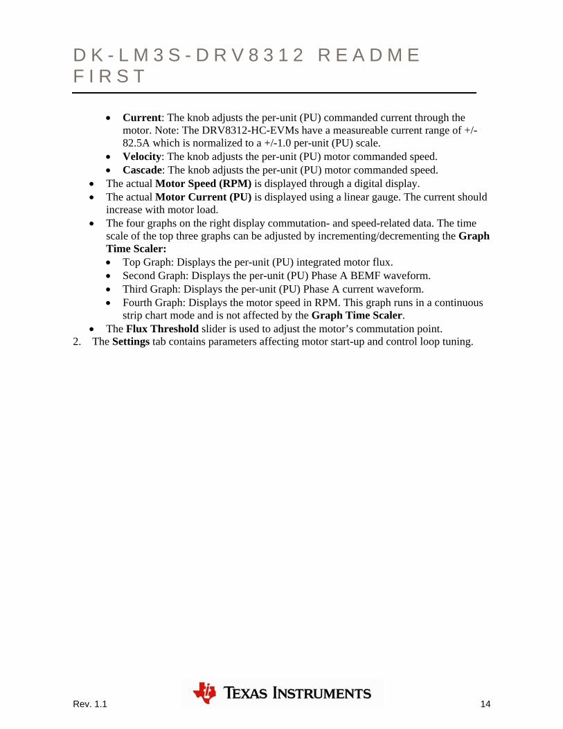
• Current: The knob adjusts the per-unit (PU) commanded current through the motor. Note: The DRV8312-HC-EVMs have a measureable current range of +/-82.5A which is normalized to a +/-1.0 per-unit (PU) scale.
• Velocity: The knob adjusts the per-unit (PU) motor commanded speed. • Cascade: The knob adjusts the per-unit (PU) motor commanded speed.
• The actual Motor Speed (RPM) is displayed through a digital display. • The actual Motor Current (PU) is displayed using a linear gauge. The current should
increase with motor load. • The four graphs on the right display commutation- and speed-related data. The time
scale of the top three graphs can be adjusted by incrementing/decrementing the Graph Time Scaler: • Top Graph: Displays the per-unit (PU) integrated motor flux. • Second Graph: Displays the per-unit (PU) Phase A BEMF waveform. • Third Graph: Displays the per-unit (PU) Phase A current waveform. • Fourth Graph: Displays the motor speed in RPM. This graph runs in a continuous
strip chart mode and is not affected by the Graph Time Scaler. • The Flux Threshold slider is used to adjust the motor’s commutation point.
2. The Settings tab contains parameters affecting motor start-up and control loop tuning.

D K - L M 3 S - D R V 8 3 1 2 R E A D M E F I R S T
Figure 6. Setup Tab
• Startup Control: These parameters control how the motor initially ramps up under forced commutation. It is necessary to get the motor spinning and generating some BEMF in order for the sensorless algorithm to latch on and take over commutation. • Startup Duty Cycle: Sets the constant PWM duty cycle given to the motor during
the forced commutation ramp-up phase. • Startup Ramp Time: Sets the time taken to complete the forced commutation
ramp-up phase. • Ramp Start Speed: Sets the initial speed for the forced commutation ramp-up
phase. • Ramp End Speed: Sets the final speed for the forced commutation ramp-up
phase. • Motor Parameters
• Pole Count: Choose the number of poles for the motor under test.
Rev. 1.1 15

D K - L M 3 S - D R V 8 3 1 2 R E A D M E F I R S T
Rev. 1.1 16
• Base Electrical Frequency: Sets the scaling of per-unit (PU) speed to motor electrical speed. For the settings shown above:
PURPMrevmechanicalHz 0.13000sec60*_1*200 ⇒=revelectricalpoles min1_
28
• Current Loop: Contains parameters associated with the current control loop. These parameters are only active when Control Mode is set to Current or Cascade. Those are the only modes which make use of the current loop. • Kp: Sets the proportional gain for the current controller. • Ki: Sets the integral gain for the current controller. • Startup Current: When current control is active the motor is driven with constant
current rather than a constant duty cycle during the forced commutation ramp up phase. This slider sets the current for this phase.
• Velocity Loop: Contains parameters associated with the velocity control loop. These parameters are only active when Control Mode is set to Velocity or Cascade. Those are the only modes which make use of the velocity loop. • Kp: Sets the proportional gain for the velocity controller. • Ki: Sets the integral gain for the velocity controller. • Velocity Loop Limit
• In Velocity Control Mode the Velocity Loop Limit Slider sets the maximum PWM duty cycle to the motor.
• In Cascade Control Mode the Velocity Loop Limit Slider sets the maximum current to the motor.
Step 6: Shutting down the motor After you are finished evaluating, do the following to shut down the motor: 1. Uncheck the Enable Motor checkbox to stop the motor.
2. Once the motor comes to a full stop, close the GUI.
3. Turn off the DC power supply. As the capacitors are charged, the PVDD LED (LED1) might remain ON for a couple of seconds. Do not touch the board until this LED goes OFF.
You can get future updates/enhancements to the GUI and/or Flash image through controlSUITE. The Flash image is meant for quick demonstration purpose only. For a more detailed explanation and understanding on the control algorithm being used and tradeoffs, see the build-level projects under the \MotorWare\rdk-drv8312 directory.

D K - L M 3 S - D R V 8 3 1 2 R E A D M E F I R S T
Rev. 1.1 17
Step 7: Programming the controlCARD with the InstaSPIN-BLDC binary The DK-LM3S-DRV8312 kit includes a controlCARD that is pre-programmed with the InstaSPIN-BLDC binary. If the controlCARD was purchased separately, or if a software update is available, the binary on the controlCARD should be programmed using the LM Flash Programmer utility To program example applications into the MDL-LM3S818CNCD module using the Stellaris ICDI: 1. Install LM Flash Programmer on a Windows PC. LM Flash Programmer is provided on
Stellaris development and evaluation kit CDs, or can be downloaded from www.ti.com/stellaris.
2. Connect the USB cable A-plug to an available port on the PC and the miniB-plug to the board.
3. Verify that both controlCARD power LEDs are lit. LED D4 indicates the status of the non-isolated microcontroller power and LED D5 indicates the status of the isolated USB power.
4. Run LM Flash Programmer.
5. In the Configuration tab, use the Quick Set control to select LM3S811 Evaluation Board. Move to the Program tab and click the Browse button. Navigate to the InstaSPIN-BLDC example directory:
C:\StellarisWare\AppNotes\sw01289\InstaSpin_GUI\ccs\Debug
6. Select the InstaSpin_GUI.bin binary file and click Open.
7. Set the “Erase Method” to “Erase Necessary Pages”, check the “Verify After Program” box, and check “Reset MCU After Program”.
8. Next, click the Program button to start the Erase, Download and Verify process. The DEBUG ACTIVE LED (D1) on the board will turn on at this time.
9. Program execution starts once Verify is complete.
Optional Step: Build InstaSPIN-BLDC Binary for Stellaris® Microcontrollers InstaSPIN-BLDC is sensorless BLDC motor control software from Texas Instruments. The InstaSPIN ZIP installer includes documentation, source, and binaries, as well as projects for Code Composer Studio (CCS). Do the following steps to build an InstaSPIN-BLDC binary from the source files. 10. Run the InstaSPIN-BLDC installer to unzip the release to a directory on your computer.
InstaSPIN is built into a self-installer that can be launched directly from the CD.

D K - L M 3 S - D R V 8 3 1 2 R E A D M E F I R S T
Rev. 1.1 18
The projects in this release assume that StellarisWare is installed in the default c:\StellarisWare directory. If StellarisWare is installed someplace else, you must specify the new location in order to build the examples. Once the files have been unzipped, the projects can be imported into your Code Composer Studio workspace.
11. To import the projects, open Code Composer Studio and select “Project” and “Import Existing CCS/CCE Eclipse Project.” In the Import CCS Eclipse Project dialog box. Make sure that “Select search-directory” is selected and use the “Browse” button to navigate to the location where the controlCARD module software was installed. The default installation directory is c:\StellarisWare\AppNotes\sw01289. Select the directory and click the OK button.
Code Composer Studio lists the two projects to import: “InstaSpin_BuildLevels” and “InstaSpin_GUI.” Select both projects and click the “Finish” button. The two new projects appear in the Projects tab in Code Composer Studio and are ready to be built.
12. Select the InstaSpin_GUI project and either the “Build Active Project” button or use the right click menu and select the “Build Project” option. Code Composer Studio compiles, links, and then generates the binary (*.bin, *.out) files. The new binary can be programmed directly from Code Composer Studio or by using LM Flash Programmer.
Additional Steps if StellarisWare is not Installed in the Default Location If StellarisWare is not in the default c:\StellarisWare directory, both projects must add a SW_ROOT environment variable so that the project can find the StellarisWare source and libraries. Do the following steps to add this environment variable:
1. To change the SW_ROOT setting, select “Project,” and then select the “Properties” from the menu options.
2. Click the “C/C++ Build” and open the Environment Tab.
3. In the Environment tab, select the Configuration tab and click the “New” button.
4. Enter “SW_ROOT” in the Name field, enter the exact location of the base directory of the StellarisWare installation in the Value field, and confirm that “Replace” is in the Operation field.
5. Click OK to close this dialog and apply the new setting.
You must do this procedure on both the “InstaSpin_BuildLevels” and the “InstaSpin_GUI” projects.
Conclusion You have now successfully set up the hardware and GUI of the DK-LM3S-DRV8312 development board and operated the motor using the GUI. For more information on using the DK-LM3S-DRV8312 kit, see the DK-LM3S-DRV8312 Baseboard HardwareReference

D K - L M 3 S - D R V 8 3 1 2 R E A D M E F I R S T
Copyright © 2011-2012 Texas Instruments, Inc. All rights reserved. Stellaris and StellarisWare are registered trademarks of Texas Instruments. ARM and Thumb are registered trademarks, and Cortex is a trademark of ARM Limited. Other names and brands may be claimed as the property of others.
Texas Instruments 108 Wild Basin Rd., Suite 350 Austin, TX 78746 http://www.ti.com/stellaris
Rev. 1.1 / SPMU273 1/24/2012
Guide which also contains information to assist you with adapting the software and hardware for a specific application.
References In addition to this document, the following references are included on the Stellaris controlCARD Development Kit CD and are also available for download at www.ti.com/stellaris: • Stellaris® LM3S818 controlCARD Module (MDL-LM3S818CNCD) README First,
publication MDL-LM3S818CNCD-RMF • Stellaris® LM3S818 controlCARD Module (MDL-LM3S818CNCD) User’s Manual,
publication MDL-LM3S818CNCD-UM • Stellaris® Development and Evaluation Kits for Code Composer Studio™ Quickstart
Guide • Stellaris® LM3S818 Microcontroller Data Sheet, publication DS-LM3S818 • StellarisWare Driver Library • StellarisWare Driver Library User’s Manual, publication SW-DRL-UG • Medium Voltage Digital Motor Control Kit for Stellaris® Microcontrollers
(DK-LM3S-DRV8312) Baseboard Hardware Reference Guide, publication DK-LM3S-DRV8312-UM
• Three-Phase PWM Motor Driver (DRV8312) Data Sheet, publication SLES256 • Sensorless Trapezoidal Control of BLDC Motors Using BEMF Integration
(InstaSPIN™-BLDC) on Stellaris® Microcontrollers Application Note, publication AN01289
Additional references include: • The GUI and corresponding Stellaris code were developed by D3 Engineering. The GUI
was created using Crosshairs Interface Designer from Crosshairs Embedded. There are links to each of the companies’ web sites within the GUI. There is also information for downloading Crosshairs Interface Designer so that you can modify the GUI that comes with this kit. The More… tab gives a brief overview of the Interface Designer software. • Crosshairs Embedded: www.crosshairsembedded.com • D3 Engineering: www.d3engineering.com

IMPORTANT NOTICE
Texas Instruments Incorporated and its subsidiaries (TI) reserve the right to make corrections, modifications, enhancements, improvements,and other changes to its products and services at any time and to discontinue any product or service without notice. Customers shouldobtain the latest relevant information before placing orders and should verify that such information is current and complete. All products aresold subject to TI’s terms and conditions of sale supplied at the time of order acknowledgment.
TI warrants performance of its hardware products to the specifications applicable at the time of sale in accordance with TI’s standardwarranty. Testing and other quality control techniques are used to the extent TI deems necessary to support this warranty. Except wheremandated by government requirements, testing of all parameters of each product is not necessarily performed.
TI assumes no liability for applications assistance or customer product design. Customers are responsible for their products andapplications using TI components. To minimize the risks associated with customer products and applications, customers should provideadequate design and operating safeguards.
TI does not warrant or represent that any license, either express or implied, is granted under any TI patent right, copyright, mask work right,or other TI intellectual property right relating to any combination, machine, or process in which TI products or services are used. Informationpublished by TI regarding third-party products or services does not constitute a license from TI to use such products or services or awarranty or endorsement thereof. Use of such information may require a license from a third party under the patents or other intellectualproperty of the third party, or a license from TI under the patents or other intellectual property of TI.
Reproduction of TI information in TI data books or data sheets is permissible only if reproduction is without alteration and is accompaniedby all associated warranties, conditions, limitations, and notices. Reproduction of this information with alteration is an unfair and deceptivebusiness practice. TI is not responsible or liable for such altered documentation. Information of third parties may be subject to additionalrestrictions.
Resale of TI products or services with statements different from or beyond the parameters stated by TI for that product or service voids allexpress and any implied warranties for the associated TI product or service and is an unfair and deceptive business practice. TI is notresponsible or liable for any such statements.
TI products are not authorized for use in safety-critical applications (such as life support) where a failure of the TI product would reasonablybe expected to cause severe personal injury or death, unless officers of the parties have executed an agreement specifically governingsuch use. Buyers represent that they have all necessary expertise in the safety and regulatory ramifications of their applications, andacknowledge and agree that they are solely responsible for all legal, regulatory and safety-related requirements concerning their productsand any use of TI products in such safety-critical applications, notwithstanding any applications-related information or support that may beprovided by TI. Further, Buyers must fully indemnify TI and its representatives against any damages arising out of the use of TI products insuch safety-critical applications.
TI products are neither designed nor intended for use in military/aerospace applications or environments unless the TI products arespecifically designated by TI as military-grade or "enhanced plastic." Only products designated by TI as military-grade meet militaryspecifications. Buyers acknowledge and agree that any such use of TI products which TI has not designated as military-grade is solely atthe Buyer's risk, and that they are solely responsible for compliance with all legal and regulatory requirements in connection with such use.
TI products are neither designed nor intended for use in automotive applications or environments unless the specific TI products aredesignated by TI as compliant with ISO/TS 16949 requirements. Buyers acknowledge and agree that, if they use any non-designatedproducts in automotive applications, TI will not be responsible for any failure to meet such requirements.
Following are URLs where you can obtain information on other Texas Instruments products and application solutions:
Products Applications
Audio www.ti.com/audio Automotive and Transportation www.ti.com/automotive
Amplifiers amplifier.ti.com Communications and Telecom www.ti.com/communications
Data Converters dataconverter.ti.com Computers and Peripherals www.ti.com/computers
DLP® Products www.dlp.com Consumer Electronics www.ti.com/consumer-apps
DSP dsp.ti.com Energy and Lighting www.ti.com/energy
Clocks and Timers www.ti.com/clocks Industrial www.ti.com/industrial
Interface interface.ti.com Medical www.ti.com/medical
Logic logic.ti.com Security www.ti.com/security
Power Mgmt power.ti.com Space, Avionics and Defense www.ti.com/space-avionics-defense
Microcontrollers microcontroller.ti.com Video and Imaging www.ti.com/video
RFID www.ti-rfid.com
OMAP Mobile Processors www.ti.com/omap
Wireless Connectivity www.ti.com/wirelessconnectivity
TI E2E Community Home Page e2e.ti.com
Mailing Address: Texas Instruments, Post Office Box 655303, Dallas, Texas 75265Copyright © 2012, Texas Instruments Incorporated


![Zestaw ewaluacyjny Tiva C Series TM4C123G Kursy EP · PDF filei debugowanie procesora Tiva TM4C123GH6PM [6]. Układ ICDI obsługuje port JTAG procesora. Układ ICDI może być używany](https://img.dokumen.tips/doc/110x75/5a898c9d7f8b9abb068b46d9/zestaw-ewaluacyjny-tiva-c-series-tm4c123g-kursy-ep-debugowanie-procesora-tiva-tm4c123gh6pm.jpg)