Embed Size (px)
Citation preview

1/2
Ref. Certif. No.
DK-49079-UL
IEC SYSTEM FOR MUTUAL RECOGNITION OF TEST CERTIFICATES FOR ELECTRICAL EQUIPMENT (IECEE) CB SCHEME
SYSTEME CEI D’ACCEPTATION MUTUELLE DE CERTIFICATS D’ESSAIS DES EQUIPEMENTS ELECTRIQUES (IECEE) METHODE OC
CB TEST CERTIFICATE CERTIFICAT D’ESSAI OCProductProduit
AC/DC Adapter
Name and address of the applicantNom et adresse du demandeur
DELTA ELECTRONICS INC 3 TUNGYUAN RD CHUNGLI INDUSTRIAL ZONE TAOYUAN COUNTY 32063 TAIWAN
Name and address of the manufacturerNom et adresse du fabricant
DELTA ELECTRONICS INC 3 TUNGYUAN RD CHUNGLI INDUSTRIAL ZONE TAOYUAN COUNTY 32063 TAIWAN
Name and address of the factoryNom et adresse de l’usine
Note: When more than one factory, please report on page 2Note: Lorsque il y plus d'une usine, veuillez utiliser la 2ème page
DELTA ELECTRONICS (THAILAND) PUBLIC CO LTD 909 SOI 9, MOO 4, BANGPOO INDUSTRIAL ESTATE (E P Z), PATTANA 1RD TAMBOL PHRAKSA AMPHUR MUANG SAMUTPRAKARN 10280 THAILAND
Additional Information on page 2Ratings and principal characteristicsValeurs nominales et caractéristiques principales
Input: AC 100-240V, 50-60Hz, 2A; Output: 19Vdc/6.32A
Trademark (if any)Marque de fabrique (si elle existe)
Delta Electronics, Inc.
Type of Manufacturer's Testing Laboratories usedType de programme du laboratoire d'essais constructeur
Model / Type Ref.Ref. De type
ADP-120RH D
Additional information (if necessary may also be reported on page 2)Les informations complémentaires (si nécessaire,, peuvent être indiqués sur la 2ème page
Additionally evaluated to EN 60950-1:2006 /A11:2009 /A1:2010 /A12:2011 /A2:2013; National Differences specified in the CB Test Report.
Additional Information on page 2A sample of the product was tested and found to be in conformity withUn échantillon de ce produit a été essayé et a été considéré conforme à la
IEC 60950-1(ed.2), IEC 60950-1(ed.2);am1, IEC 60950-1(ed.2);am2
As shown in the Test Report Ref. No. which forms part of this CertificateComme indiqué dans le Rapport d’essais numéro de référence qui constitue partie de ce Certificat
E131881-A1542-CB-2 issued on 2015-10-15, E131881-A1542-CB-2 issued on 2015-06-24, E131881-A1542-CB-2 issued on 2015-06-01
This CB Test Certificate is issued by the National Certification BodyCe Certificat d’essai OC est établi par l’Organisme National de Certification
UL (US), 333 Pfingsten Rd IL 60062, Northbrook, USA
UL (Demko), Borupvang 5A DK-2750 Ballerup, DENMARK
UL (JP), Marunouchi Trust Tower Main Building 6F, 1-8-3 Marunouchi, Chiyoda-ku, Tokyo 100-0005, JAPAN
UL (CA), 7 Underwriters Road, Toronto, M1R 3B4 Ontario, CANADA
For full legal entity names see www.ul.com/ncbnames
Date: 2015-10-15
Signature:
Jan-Erik Storgaard

2/2
Ref. Certif. No.
DK-49079-UL
Factories:DELTA ELECTRONICS (JIANGSU) LTD.NO 1688 JIANGXING EAST RD WUJIANG ECONOMIC DEVELOPMENT ZONE WUJIANG CITY JIANGSU PROVINCE 215200CHINADELTA ELECTRONICS POWER(DONGGUAN) CO LTDDELTA INDUSTRIAL ESTATE SHIJIE TOWN DONGGUAN CITY GUANGDONG PROVINCE 523308CHINA
Additional information (if necessary)Information complémentaire (si nécessaire)
UL (US), 333 Pfingsten Rd IL 60062, Northbrook, USA
UL (Demko), Borupvang 5A DK-2750 Ballerup, DENMARK
UL (JP), Marunouchi Trust Tower Main Building 6F, 1-8-3 Marunouchi, Chiyoda-ku, Tokyo 100-0005, JAPAN
UL (CA), 7 Underwriters Road, Toronto, M1R 3B4 Ontario, CANADA
For full legal entity names see www.ul.com/ncbnames
Signature: Jan-Erik Storgaard
Date: 2015-10-15
1/2
Ref. Certif. No.
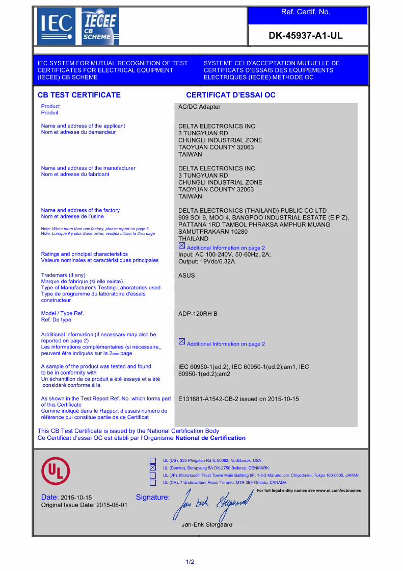
DK-45937-A1-UL
IEC SYSTEM FOR MUTUAL RECOGNITION OF TEST CERTIFICATES FOR ELECTRICAL EQUIPMENT (IECEE) CB SCHEME
SYSTEME CEI D’ACCEPTATION MUTUELLE DE CERTIFICATS D’ESSAIS DES EQUIPEMENTS ELECTRIQUES (IECEE) METHODE OC
CB TEST CERTIFICATE CERTIFICAT D’ESSAI OCProductProduit
AC/DC Adapter
Name and address of the applicantNom et adresse du demandeur
DELTA ELECTRONICS INC 3 TUNGYUAN RD CHUNGLI INDUSTRIAL ZONE TAOYUAN COUNTY 32063 TAIWAN
Name and address of the manufacturerNom et adresse du fabricant
DELTA ELECTRONICS INC 3 TUNGYUAN RD CHUNGLI INDUSTRIAL ZONE TAOYUAN COUNTY 32063 TAIWAN
Name and address of the factoryNom et adresse de l’usine
Note: When more than one factory, please report on page 2Note: Lorsque il y plus d'une usine, veuillez utiliser la 2ème page
DELTA ELECTRONICS (THAILAND) PUBLIC CO LTD 909 SOI 9, MOO 4, BANGPOO INDUSTRIAL ESTATE (E P Z), PATTANA 1RD TAMBOL PHRAKSA AMPHUR MUANG SAMUTPRAKARN 10280 THAILAND
Additional Information on page 2Ratings and principal characteristicsValeurs nominales et caractéristiques principales
Input: AC 100-240V, 50-60Hz, 2A; Output: 19Vdc/6.32A
Trademark (if any)Marque de fabrique (si elle existe)
ASUS
Type of Manufacturer's Testing Laboratories usedType de programme du laboratoire d'essais constructeur
Model / Type Ref.Ref. De type
ADP-120RH B
Additional information (if necessary may also be reported on page 2)Les informations complémentaires (si nécessaire,, peuvent être indiqués sur la 2ème page
Additional Information on page 2
A sample of the product was tested and found to be in conformity withUn échantillon de ce produit a été essayé et a été considéré conforme à la
IEC 60950-1(ed.2), IEC 60950-1(ed.2);am1, IEC 60950-1(ed.2);am2
As shown in the Test Report Ref. No. which forms part of this CertificateComme indiqué dans le Rapport d’essais numéro de référence qui constitue partie de ce Certificat
E131881-A1542-CB-2 issued on 2015-10-15
This CB Test Certificate is issued by the National Certification BodyCe Certificat d’essai OC est établi par l’Organisme National de Certification
UL (US), 333 Pfingsten Rd IL 60062, Northbrook, USA
UL (Demko), Borupvang 5A DK-2750 Ballerup, DENMARK
UL (JP), Marunouchi Trust Tower Main Building 6F, 1-8-3 Marunouchi, Chiyoda-ku, Tokyo 100-0005, JAPAN
UL (CA), 7 Underwriters Road, Toronto, M1R 3B4 Ontario, CANADA
For full legal entity names see www.ul.com/ncbnames
Date: 2015-10-15 Original Issue Date: 2015-06-01
Signature:
Jan-Erik Storgaard

2/2
Ref. Certif. No.
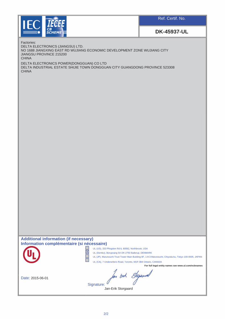
DK-45937-A1-UL
Factories:DELTA ELECTRONICS (JIANGSU) LTD.NO 1688 JIANGXING EAST RD WUJIANG ECONOMIC DEVELOPMENT ZONE WUJIANG CITY JIANGSU PROVINCE 215200CHINADELTA ELECTRONICS POWER(DONGGUAN) CO LTDDELTA INDUSTRIAL ESTATE SHIJIE TOWN DONGGUAN CITY GUANGDONG PROVINCE 523308CHINA
Additional Information: Additionally evaluated to EN 60950-1:2006 /A11:2009 /A1:2010 /A12:2011 /A2:2013; National Differences specified in the CB Test Report.
The original report was modified to include the following changes/additions: Revised test report.
Additional information (if necessary)Information complémentaire (si nécessaire)
UL (US), 333 Pfingsten Rd IL 60062, Northbrook, USA
UL (Demko), Borupvang 5A DK-2750 Ballerup, DENMARK
UL (JP), Marunouchi Trust Tower Main Building 6F, 1-8-3 Marunouchi, Chiyoda-ku, Tokyo 100-0005, JAPAN
UL (CA), 7 Underwriters Road, Toronto, M1R 3B4 Ontario, CANADAFor full legal entity names see www.ul.com/ncbnames
Signature: Jan-Erik Storgaard
Date: 2015-10-15Original Issue Date: 2015-06-01

Issue Date: 2015-06-01 Page 1 of 10 Report Reference # E131881-A1542-CB-2
Amendment 1 2015-10-15
TRF No. IEC60950_1F This report issued under the responsibility of UL
Test Report issued under
the responsibility of:
TEST REPORT IEC 60950-1
Information technology equipment - Safety - Part 1: General requirements
Report Reference No .................. : E131881-A1542-CB-2
Date of issue ................................. : 2015-06-01
Total number of pages .................. : 10
CB Testing Laboratory ............... : Underwriters Laboratories Taiwan Co., Ltd.
Address ......................................... : 260 Da-Yeh Road, 112 Peitou Taipei City, Chinese Taipei
Applicant's name ........................ :
Address ......................................... :
DELTA ELECTRONICS INC 3 TUNGYUAN RD CHUNGLI INDUSTRIAL ZONE TAOYUAN COUNTY 32063 TAIWAN
Test specification:
Standard ........................................ : IEC 60950-1:2005 (Second Edition); Am1:2009 + Am2:2013
Test procedure .............................. : CB Scheme
Non-standard test method ............ : N/A
Test Report Form No. ................. : IEC60950_1F
Test Report Form originator .......... : SGS Fimko Ltd
Master TRF ................................... : Dated 2014-02
Copyright © 2014 Worldwide System for Conformity Testing and Certification of Electrotechnical Equipment and Components (IECEE), Geneva, Switzerland. All rights reserved. This publication may be reproduced in whole or in part for non-commercial purposes as long as the IECEE is acknowledged as copyright owner and source of the material. IECEE takes no responsibility for and will not assume liability for damages resulting from the reader's interpretation of the reproduced material due to its placement and context. If this test Report is used by non-IECEE members, the IECEE/IEC logo and the reference to the CB Scheme procedure shall be removed. This report is not valid as a CB Test Report unless signed by an approved CB Testing Laboratory and appended to a CB Test Certificate issued by an NCB in accordance with IECEE 02.
General disclaimer The test results presented in this report relate only to the object tested. This report shall not be reproduced, except in full, without the written approval of the Issuing CB Testing Laboratory. The authenticity of this Test Report and its contents can be verified by contacting the NCB, responsible for this Test Report.

Issue Date: 2015-06-01 Page 2 of 10 Report Reference # E131881-A1542-CB-2
Amendment 1 2015-10-15
TRF No. IEC60950_1F This report issued under the responsibility of UL
Test item description .................. : AC/DC Adapter
Trade Mark .................................... : ASUS (ADP-120RH B), Delta Electronics, Inc. (ADP-120RH D)
Manufacturer ................................. : DELTA ELECTRONICS INC 3 TUNGYUAN RD CHUNGLI INDUSTRIAL ZONE TAOYUAN COUNTY 32063 TAIWAN
Model/Type reference ................... : ADP-120RH B, ADP-120RH D
Ratings .......................................... : Input: AC 100-240V, 50-60Hz, 2A; Output: 19Vdc/6.32A
Issue Date: 2015-06-01 Page 3 of 10 Report Reference # E131881-A1542-CB-2
Amendment 1 2015-10-15
TRF No. IEC60950_1F This report issued under the responsibility of UL
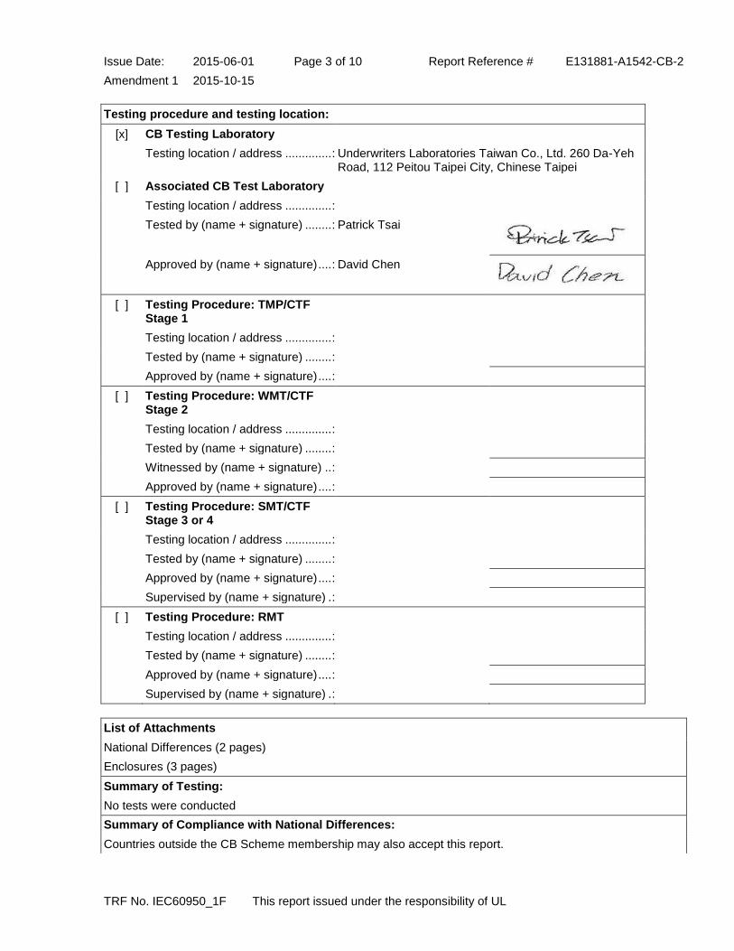
Testing procedure and testing location:
[x] CB Testing Laboratory
Testing location / address .............. : Underwriters Laboratories Taiwan Co., Ltd. 260 Da-Yeh Road, 112 Peitou Taipei City, Chinese Taipei
[ ] Associated CB Test Laboratory
Testing location / address .............. :
Tested by (name + signature) ........ : Patrick Tsai
Approved by (name + signature) .... : David Chen
[ ] Testing Procedure: TMP/CTF Stage 1
Testing location / address .............. :
Tested by (name + signature) ........ :
Approved by (name + signature) .... :
[ ] Testing Procedure: WMT/CTF Stage 2
Testing location / address .............. :
Tested by (name + signature) ........ :
Witnessed by (name + signature) .. :
Approved by (name + signature) .... :
[ ] Testing Procedure: SMT/CTF Stage 3 or 4
Testing location / address .............. :
Tested by (name + signature) ........ :
Approved by (name + signature) .... :
Supervised by (name + signature) . :
[ ] Testing Procedure: RMT
Testing location / address .............. :
Tested by (name + signature) ........ :
Approved by (name + signature) .... :
Supervised by (name + signature) . :
List of Attachments
National Differences (2 pages)
Enclosures (3 pages)
Summary of Testing:
No tests were conducted
Summary of Compliance with National Differences:
Countries outside the CB Scheme membership may also accept this report.

Issue Date: 2015-06-01 Page 4 of 10 Report Reference # E131881-A1542-CB-2
Amendment 1 2015-10-15
TRF No. IEC60950_1F This report issued under the responsibility of UL
List of countries addressed: AR, AT, AU, BE, BG, BY, CA, CH, CN, CS, CZ, DE, DK, ES, EU, FI, FR, GB, GR, HU, IL, IN, IT, JP, KR, MY, NL, NO, NZ, PL, RO, SA, SE, SG, SI, SK, UA, US, ZA
The product fulfills the requirements of: EN 60950-1:2006 + A1:2010 + A11:2009 + A12:2011 + A2:2013
Copy of Marking Plate - Refer to Enclosure titled Marking Plate for copy.

Issue Date: 2015-06-01 Page 5 of 10 Report Reference # E131881-A1542-CB-2
Amendment 1 2015-10-15
TRF No. IEC60950_1F This report issued under the responsibility of UL
Test item particulars :
Equipment mobility ...............................................: transportable/movable
Connection to the mains ......................................: pluggable A
Operating condition ..............................................: continuous
Access location ....................................................: operator accessible
Over voltage category (OVC) ..............................: OVC II
Mains supply tolerance (%) or absolute mains supply values ...................................................................: +10%, -10% (Manufacturer declared)
Tested for IT power systems ...............................: No
IT testing, phase-phase voltage (V) .....................: N/A
Class of equipment ..............................................: Special Application - Functional Earthing
Considered current rating of protective device as part of the building installation (A) ...............................: 16 (20A for North America)
Pollution degree (PD) ...........................................: PD 2
IP protection class ................................................: IP X0
Altitude of operation (m) .......................................: up to 5,000m
Altitude of test laboratory (m) ...............................: less than 2,000 m
Mass of equipment (kg) .......................................: Approx. 0.44
Possible test case verdicts:
- test case does not apply to the test object ........... : N / A
- test object does meet the requirement ................. : P(Pass)
- test object does not meet the requirement ........... : F(Fail)
Testing:
Date(s) of receipt of test item ...............................: N/A
Date(s) of Performance of tests ...........................: N/A
General remarks:
"(see Enclosure #)" refers to additional information appended to the report. "(see appended table)" refers to a table appended to the report. Throughout this report a point is used as the decimal separator.
Manufacturer's Declaration per Sub Clause 4.2.5 of IECEE 02: The application for obtaining a CB Test Certificate includes more than one factory and a declaration from the Manufacturer stating that the sample(s) submitted for evaluation is (are) representative of the products from each factory has been provided ...... When differences exist, they shall be identified in the General Product Information section.
Yes
Name and address of Factory(ies): DELTA ELECTRONICS (THAILAND) PUBLIC CO LTD 909 SOI 9, MOO 4, BANGPOO INDUSTRIAL ESTATE (E P Z), PATTANA 1RD TAMBOL PHRAKSA AMPHUR MUANG SAMUTPRAKARN 10280 THAILAND

Issue Date: 2015-06-01 Page 6 of 10 Report Reference # E131881-A1542-CB-2
Amendment 1 2015-10-15
TRF No. IEC60950_1F This report issued under the responsibility of UL
DELTA ELECTRONICS (JIANGSU) LTD. NO 1688 JIANGXING EAST RD WUJIANG ECONOMIC DEVELOPMENT ZONE WUJIANG CITY JIANGSU PROVINCE 215200 CHINA DELTA ELECTRONICS POWER(DONGGUAN) CO LTD DELTA INDUSTRIAL ESTATE SHIJIE TOWN DONGGUAN CITY GUANGDONG PROVINCE 523308 CHINA
GENERAL PRODUCT INFORMATION:
Report Summary
The original report was modified on 2015-10-15 to include the following changes/additions: This test Report should be read in conjunction with the original report No.: 1) E131881-A1542-CB-2-Reissue, issue date 2015-06-01 with CB Certificate No. DK-45937-UL, issue date 2015-06-01. 2) E131881-A1542-CB-2-Correction-1, issue date 2015-06-24 with CB Certificate No. DK-45937-M1-UL, issue date 2015-06-24. This report was deemed to be amended due to: 1) Added a new model ADP-120RH D which is similar to model ADP-120RH B except for trademark. 2) Added a new trademark for the model ADP-120RH D.
Product Description
Consist of electronic components mounted on PWB, housed with a plastic enclosure. There are Construction A and B in models ADP-120RH B and ADP-120RH D. See Enclosure ID 7-03 for difference details.
Model Differences
Model ADP-120RH D is similar to model ADP-120RH B except for model designation and trademark.
Additional Information
- The original report was modified on 2015-05-28 to include the following changes/additions: This test Report is reissued from report No.: 1. E131881-A1542-CB-1,issued date 2012-09-27, with CB Certificate No.DK-28282-UL, issued date 2012-09-27, 2. E131881-A1542-CB-Amenment-1,issued date 2012-10-18, with CB Certificate No.DK-28282-A1-UL, issued date 2012-10-18 3. E131881-A1542-CB-Amenment-2,issued date 2012-11-01, with CB Certificate No.DK-28282-A2-UL, issued date 2012-11-02. 4. E131881-A1542-CB-Amenment-3,issued date 2012-12-21, with CB Certificate No.DK-28282-A3-UL, issued date 2012-12-21. - This report was deemed to reissue due to employing: Alternate Construction B: Model ADP-120RH B and upgrade standard to IEC 60950-1:2005 (Second Edition); Am1:2009 + Am2:2013 - Only limited tests were necessary as below: END PRODUCT REFERENCE PAGE GENERAL GUIDELINES

Issue Date: 2015-06-01 Page 7 of 10 Report Reference # E131881-A1542-CB-2
Amendment 1 2015-10-15
TRF No. IEC60950_1F This report issued under the responsibility of UL
POWER SUPPLY REFERENCE PAGE 1.6.2 - INPUT TEST: SINGLE-PHASE 2.1.1.5, 2.1.2, 1.2.8.10 ENERGY HAZARD MEASUREMENTS 2.1.1.7 CAPACITANCE DISCHARGE TEST 2.2.2, 2.2.3, 2.2.4, PART 22 6.1 SELV RELIABILITY TEST INCLUDING HAZARDOUS VOLTAGE MEASUREMENTS 2.4.1, 2.4.2 - LIMITED CURRENT CIRCUIT MEASUREMENTS 2.9.1, 2.9.2, 5.2.2 HUMIDITY TEST 2.10.2 DETERMINATION OF WORKING VOLTAGE - WORKING VOLTAGE MEASUREMENT TEST 3.2.6, 4.2.1, 4.2.7 STRAIN RELIEF TEST 4.2.1 - 4.2.4 - STEADY FORCE TESTS 4.2.5, 4.2.1, PART 22 10.2 IMPACT TEST 4.2.6, 4.2.1 DROP TEST 4.2.7, 4.2.1 STRESS RELIEF TEST 4.5.1, 1.4.12, 1.4.13 HEATING TEST 5.1, ANNEX D TOUCH CURRENT TEST (SINGLE-PHASE; TN/TT SYSTEM) 5.2.2 ELECTRIC STRENGTH TEST 5.3.1, 5.3.4, 5.3.7 COMPONENT FAILURE TEST 5.3.3, 5.3.7b, ANNEX C.1 - TRANSFORMER ABNORMAL OPERATION TEST 5.3.7 POWER SUPPLY OUTPUT SHORT-CIRCUIT/OVERLOAD TEST
Technical Considerations
The product was submitted and evaluated for use at the maximum ambient temperature (Tma) permitted by the manufacturer’s specification of: 40 degree C
The means of connection to the mains supply is: Detachable power cord, Pluggable A
The product is intended for use on the following power systems: TN
The equipment disconnect device is considered to be: Appliance inlet
The product was investigated to the following additional standards: EN 60950-1:2006 + A11:2009 + A1:2010 + A12:2011 + A2:2013 (which includes all European national differences, including those specified in this test report). IEC 60664-1: 2007 table A.2. The Clearances and Creepage Distances have additionally been assessed for suitability up to 5,000m elevation.
The following accessible locations (with circuit/schematic designation) are within a limited current circuit: CY1 secondary
The following are available from the Applicant upon request: Installation (Safety) Instructions / Manual
Type MST made by Conquer Electronics Co., Ltd. was used for Fuse(F1) during the abnormal test for Model ADP-120RH B construction A; Type 5ET made by Hollyland Co. was used for Fuse(F1) during the abnormal test for Model ADP-120RH B construction B. --
Abbreviations used in the report:
- normal condition ............................................ : N.C. - single fault condition ....................................... : S.F.C
- operational insulation ..................................... : OP - basic insulation .............................................. : BI
- basic insulation between parts of opposite polarity:
BOP
- supplementary insulation ............................... : SI
- double insulation ............................................ : DI - reinforced insulation ...................................... : RI
Indicate used abbreviations (if any)

Issue Date: 2015-06-01 Page 8 of 10 Report Reference # E131881-A1542-CB-2
Amendment 1 2015-10-15
IEC 60950-1
Clause Requirement + Test Result - Remark Verdict
TRF No. IEC60950_1F This report issued under the responsibility of UL
1.7.1.2 Manufacturer's name or trademark or identification mark .................................... :
ASUS or "E131881" or Delta Electronics, Inc.
Pass
Model identification or type reference ...... : ADP-120RH B (ASUS) ADP-120RH D (Delta Electronics, Inc.)
Pass
2.1.1.7 Measured voltage (V); time-constant (s) .. : Construction A Test voltage 264V, 60Hz, CX1=0.33uF, R1=R2=2Mohm. - the voltage at the time of disconnection, Vo=372 V pk. - 37% Vo=137.64V pk. - Vtc=112Vpk measured at 1 s after disconnection. Construction B Test voltage 264V, 60Hz, CX1=0.33uF, R1=R2=2Mohm. - the voltage at the time of disconnection, Vo=408 V pk. - 37% Vo=150.96V pk. - Vtc=24Vpk measured at 1 s after disconnection.
-

Issue Date: 2015-06-01 Page 9 of 10 Report Reference # E131881-A1542-CB-2
Amendment 1 2015-10-15
IEC 60950-1
Clause Requirement + Test Result - Remark Verdict
TRF No. IEC60950_1F This report issued under the responsibility of UL
2.5 TABLE: Limited power sources N/A
Circuit output tested:
Note: Measured Uoc (V) with all load circuits disconnected:
Components Sample No. Uoc (V) Isc (A) VA
Meas. Limit Meas. Limit
supplementary information:
4.3.8 TABLE: Batteries N/A
The tests of 4.3.8 are applicable only when appropriate battery data is not available.
Is it possible to install the battery in a reverse polarity position?
Non-rechargeable batteries
Rechargeable batteries
Discharging Un- intentional charging
Charging Discharging Reversed charging
Meas. current
Manuf. specs.
Meas. current
Manuf. specs. Meas. current
Manuf. specs.
Meas.
current
Manuf.
specs.
Test results: Verdict
- Chemical leaks
- Explosion of the battery
- Emission of flame or expulsion of molten metal
- Electric strength tests of equipment after completion of tests
supplementary information:
4.3.8 TABLE: Batteries N/A
Battery category (lithium, NiMh, NiCad, lithium ion, etc.)
Manufacturer
Type / model
Voltage
Capacity (mAh)
Tested and Certified by (incl. Ref. No.)
Circuit protection diagram (refer to indicated supplement of Enclosure - Miscellaneous)
MARKINGS AND INSTRUCTIONS (1.7.12, 1.7.15)
Location of replaceable battery
Language(s)
Close to the battery
In the servicing instructions
In the operating instructions
supplementary information:

Issue Date: 2015-06-01 Page 10 of 10 Report Reference # E131881-A1542-CB-2
Amendment 1 2015-10-15
IEC 60950-1
Clause Requirement + Test Result - Remark Verdict
TRF No. IEC60950_1F This report issued under the responsibility of UL
4.5 TABLE: Thermal requirements Pass
Supply voltage (V) : see below see below see below see below
see below
---
Ambient Tmin (°C) : -- -- -- -- -- ---
Ambient Tmax (°C) : -- -- -- -- -- ---
Maximum measured temperature T of part/at: T (°C) #1 T (°C) #2 T (°C) #3 T (°C) #4
T (°C) #5 Allowed Tmax (°C)
Temperature T of winding:
t1 (°C) R1 (ohm)
t2 (°C) R2 (ohm) T (°C) Allowed Tmax (°C)
Insulation class
supplementary information:

Issue Date: 2015-06-01 Page 1 of 2 Report Reference # E131881-A1542-CB-2
Amendment 1 2015-10-15
This report issued under the responsibility of UL
Enclosure National Differences
Argentina
Australia / New Zealand Austria** Belarus*
Belgium** Bulgaria**
China Czech Republic**
Denmark Finland France** Germany Greece**
Group Hungary**
India* Israel Italy** Japan Korea
Malaysia* Netherlands**
Norway Poland**
Romania** Saudi Arabia*
Serbia** Singapore* Slovakia** Slovenia**
South Africa* Spain
Sweden Switzerland
USA / Canada Ukraine*
United Kingdom
* No National Differences Declared ** Only Group Differences

Issue Date: 2015-06-01 Page 2 of 2 Report Reference # E131881-A1542-CB-2
Amendment 1 2015-10-15
IEC 60950-1:2005
SubClause Difference + Test Result - Remark Verdict
This report issued under the responsibility of UL
NOTE: National differences are not listed for countries that have no declared national differences or that conform to previously stated Group differences.

Issue Date: 2015-06-01 Page 1 of 3 Report Reference # E131881-A1542-CB-2
Amendment 1 2015-10-15 Enclosures
This report issued under the responsibility of UL
Enclosures
Type Supplement Id Description
Photographs 3-01 External View - Inlet side
Photographs 3-02 External View - Cover side
Photographs 3-03 External View - Chassis side
Photographs 3-04 Side View 1
Photographs 3-05 Side View 2
Photographs 3-06 Construction A - Internal View 1- with metal shielding
Photographs 3-07 Construction A - Internal View 2- with metal shielding
Photographs 3-08 Construction A - internal 3 -without metal shielding
Photographs 3-09 Construction A - internal 4 -without metal shielding
Photographs 3-10 Construction A - Component Side View
Photographs 3-11 Construction A - Trace Side View
Photographs 3-12 Construction A - Glue Point View 1
Photographs 3-13 Construction A - Glue Point View 2
Photographs 3-15 Construction A - Trace side view(add one tape on outside of transformer)
Photographs 3-16 Component side(transformer with tape)
Photographs 3-17 Construction A - Transformer view-1(with tape)
Photographs 3-18 Construction A - Transformer view-2(with tape)
Photographs 3-19 Construction A - Trace side view( one tape was added on transformer MV-MP12664)
Photographs 3-20 Construction B Internal View 1- with metal shielding
Photographs 3-21 Construction B Internal View 2- with metal shielding
Photographs 3-22 Construction B Internal View 3- open metal shielding
Photographs 3-23 Construction B Component side
Photographs 3-24 Construction B - Trace side
Diagrams 4-01 Construction A - Line Filter FL1 Spec
Diagrams 4-02 Construction A - Line Filter FL2 Spec
Diagrams 4-03 Line Filter L1 Spec
Diagrams 4-04 Construction A - Line Filter L2 Spec
Diagrams 4-05 Construction A - Transformer T1 Spec
Diagrams 4-06 Enclosure chassis
Diagrams 4-07 Enclosure cover
Diagrams 4-08 Output Cord and strain relief
Diagrams 4-09 Construction A - Shield Top (EMI Shielding)

Issue Date: 2015-06-01 Page 2 of 3 Report Reference # E131881-A1542-CB-2
Amendment 1 2015-10-15 Enclosures
This report issued under the responsibility of UL
Diagrams 4-10 Construction A - Shield Ass'y (EMI Shielding)
Diagrams 4-12 Construction A - Heatsink Spec
Diagrams 4-13 Construction A - Glue Location and Amount
Diagrams 4-14 Construction A - Working voltage location(A1 to A4)
Diagrams 4-15 Construction A - Alternative transformer T1 spec.
Diagrams 4-16 Construction B - Line Filter FL1 Spec
Diagrams 4-17 Construction B - Line Filter FL2 Spec
Diagrams 4-18 Construction B - Line Filter L2 Spec
Diagrams 4-19 Construction B - Alternative transformer T1 spec. (MV-MP15038)
Diagrams 4-20 Construction B - Shield Ass'y
Diagrams 4-21 Construction B - Shield Top
Diagrams 4-22 Construction B Heatsink (HS1, HS2, HS3)
Diagrams 4-23 Construction B - Glue location
Schematics + PWB 5-01 Construction A - Model ADP-120RH B PWB Layout (P/N: ADP-120RH BA)
Schematics + PWB 5-02 Construction B - Model ADP-120RH B PWB Layout (P/N: ADP-120RH DA)
Miscellaneous 7-01 Multiple Factories Declaration
Miscellaneous 7-02 TMP test equipment list
Miscellaneous 7-03 Model difference
Marking Plate 13-01 Marking Plate for Model ADP-120RH B
Marking Plate 13-02 Marking Plate for Model ADP-120RH D

Issue Date: 2015-06-01 Page 3 of 3 Report Reference # E131881-A1542-CB-2
Amendment 1 2015-10-15 Enclosures
This report issued under the responsibility of UL
MarkingPlate ID 13-02

1/2
Ref. Certif. No.
DK-45937-UL
IEC SYSTEM FOR MUTUAL RECOGNITION OF TEST CERTIFICATES FOR ELECTRICAL EQUIPMENT (IECEE) CB SCHEME
SYSTEME CEI D’ACCEPTATION MUTUELLE DE CERTIFICATS D’ESSAIS DES EQUIPEMENTS ELECTRIQUES (IECEE) METHODE OC
CB TEST CERTIFICATE CERTIFICAT D’ESSAI OCProductProduit
AC/DC Adapter
Name and address of the applicantNom et adresse du demandeur
DELTA ELECTRONICS INC 3 TUNGYUAN RD CHUNGLI INDUSTRIAL ZONE TAOYUAN COUNTY 32063 TAIWAN
Name and address of the manufacturerNom et adresse du fabricant
DELTA ELECTRONICS INC 3 TUNGYUAN RD CHUNGLI INDUSTRIAL ZONE TAOYUAN COUNTY 32063 TAIWAN
Name and address of the factoryNom et adresse de l’usine
Note: When more than one factory, please report on page 2Note: Lorsque il y plus d'une usine, veuillez utiliser la 2ème page
DELTA ELECTRONICS (THAILAND) PUBLIC CO LTD 909 SOI 9, MOO 4, BANGPOO INDUSTRIAL ESTATE (E P Z), PATTANA 1RD TAMBOL PHRAKSA AMPHUR MUANG SAMUTPRAKARN 10280 THAILAND
Additional Information on page 2Ratings and principal characteristicsValeurs nominales et caractéristiques principales
Input: AC 100-240V, 50-60Hz, 2A; Output: 19Vdc/6.32A
Trademark (if any)Marque de fabrique (si elle existe)
ASUS
Type of Manufacturer's Testing Laboratories usedType de programme du laboratoire d'essais constructeur
Model / Type Ref.Ref. De type
ADP-120RH B
Additional information (if necessary may also be reported on page 2)Les informations complémentaires (si nécessaire,, peuvent être indiqués sur la 2ème page
Additionally evaluated to EN 60950-1:2006 /A11:2009 /A1:2010 /A12:2011 /A2:2013; National Differences specified in the CB Test Report.
Additional Information on page 2A sample of the product was tested and found to be in conformity withUn échantillon de ce produit a été essayé et a été considéré conforme à la
IEC 60950-1(ed.2), IEC 60950-1(ed.2);am1, IEC 60950-1(ed.2);am2
As shown in the Test Report Ref. No. which forms part of this CertificateComme indiqué dans le Rapport d’essais numéro de référence qui constitue partie de ce Certificat
E131881-A1542-CB-2 issued on 2015-06-01
This CB Test Certificate is issued by the National Certification BodyCe Certificat d’essai OC est établi par l’Organisme National de Certification
UL (US), 333 Pfingsten Rd IL 60062, Northbrook, USA
UL (Demko), Borupvang 5A DK-2750 Ballerup, DENMARK
UL (JP), Marunouchi Trust Tower Main Building 6F, 1-8-3 Marunouchi, Chiyoda-ku, Tokyo 100-0005, JAPAN
UL (CA), 7 Underwriters Road, Toronto, M1R 3B4 Ontario, CANADA
For full legal entity names see www.ul.com/ncbnames
Date: 2015-06-01
Signature:
Jan-Erik Storgaard JaJJ n-Erik Storgggggggggggggggaard
2/2
Ref. Certif. No.
DK-45937-UL
Factories:DELTA ELECTRONICS (JIANGSU) LTD.NO 1688 JIANGXING EAST RD WUJIANG ECONOMIC DEVELOPMENT ZONE WUJIANG CITY JIANGSU PROVINCE 215200CHINADELTA ELECTRONICS POWER(DONGGUAN) CO LTDDELTA INDUSTRIAL ESTATE SHIJIE TOWN DONGGUAN CITY GUANGDONG PROVINCE 523308CHINA
Additional information (if necessary)Information complémentaire (si nécessaire)
UL (US), 333 Pfingsten Rd IL 60062, Northbrook, USA
UL (Demko), Borupvang 5A DK-2750 Ballerup, DENMARK
UL (JP), Marunouchi Trust Tower Main Building 6F, 1-8-3 Marunouchi, Chiyoda-ku, Tokyo 100-0005, JAPAN
UL (CA), 7 Underwriters Road, Toronto, M1R 3B4 Ontario, CANADAFor full legal entity names see www.ul.com/ncbnames
Signature: Jan-Erik Storgaard
Date: 2015-06-01

Issue Date: 2015-06-01 Page 1 of 65 Report Reference # E131881-A1542-CB-2
TRF No. IEC60950_1F This report issued under the responsibility of UL
Test Report issued under
the responsibility of:
TEST REPORT IEC 60950-1
Information technology equipment - Safety - Part 1: General requirements
Report Reference No .................. : E131881-A1542-CB-2
Date of issue ................................. : 2015-06-01
Total number of pages .................. : 65
CB Testing Laboratory ............... : Underwriters Laboratories Taiwan Co., Ltd.
Address ......................................... : 260 Da-Yeh Road, 112 Peitou Taipei City, Chinese Taipei
Applicant's name ........................ :
Address ......................................... :
DELTA ELECTRONICS INC 3 TUNGYUAN RD CHUNGLI INDUSTRIAL ZONE TAOYUAN COUNTY 32063 TAIWAN
Test specification:
Standard ........................................ : IEC 60950-1:2005 (Second Edition); Am1:2009 + Am2:2013
Test procedure .............................. : CB Scheme
Non-standard test method ............ : N/A
Test Report Form No. ................. : IEC60950_1F
Test Report Form originator .......... : SGS Fimko Ltd
Master TRF ................................... : Dated 2014-02
Copyright © 2014 Worldwide System for Conformity Testing and Certification of Electrotechnical Equipment and Components (IECEE), Geneva, Switzerland. All rights reserved. This publication may be reproduced in whole or in part for non-commercial purposes as long as the IECEE is acknowledged as copyright owner and source of the material. IECEE takes no responsibility for and will not assume liability for damages resulting from the reader's interpretation of the reproduced material due to its placement and context. If this test Report is used by non-IECEE members, the IECEE/IEC logo and the reference to the CB Scheme procedure shall be removed. This report is not valid as a CB Test Report unless signed by an approved CB Testing Laboratory and appended to a CB Test Certificate issued by an NCB in accordance with IECEE 02.
General disclaimer The test results presented in this report relate only to the object tested. This report shall not be reproduced, except in full, without the written approval of the Issuing CB Testing Laboratory. The authenticity of this Test Report and its contents can be verified by contacting the NCB, responsible for this Test Report.

Issue Date: 2015-06-01 Page 2 of 65 Report Reference # E131881-A1542-CB-2
TRF No. IEC60950_1F This report issued under the responsibility of UL
Test item description .................. : AC/DC Adapter
Trade Mark .................................... : ASUS
Manufacturer ................................. : DELTA ELECTRONICS INC 3 TUNGYUAN RD CHUNGLI INDUSTRIAL ZONE TAOYUAN COUNTY 32063 TAIWAN
Model/Type reference ................... : ADP-120RH B
Ratings .......................................... : Input: AC 100-240V, 50-60Hz, 2A; Output: 19Vdc/6.32A

Issue Date: 2015-06-01 Page 3 of 65 Report Reference # E131881-A1542-CB-2
TRF No. IEC60950_1F This report issued under the responsibility of UL
Testing procedure and testing location:
[x] CB Testing Laboratory
Testing location / address .............. : Underwriters Laboratories Taiwan Co., Ltd. 260 Da-Yeh Road, 112 Peitou Taipei City, Chinese Taipei
[ ] Associated CB Test Laboratory
Testing location / address .............. :
Tested by (name + signature) ........ : David Chen
Approved by (name + signature) .... : Stalling Chen
[ ] Testing Procedure: TMP/CTF Stage 1
Testing location / address .............. :
Tested by (name + signature) ........ :
Approved by (name + signature) .... :
[ ] Testing Procedure: WMT/CTF Stage 2
Testing location / address .............. :
Tested by (name + signature) ........ :
Witnessed by (name + signature) .. :
Approved by (name + signature) .... :
[ ] Testing Procedure: SMT/CTF Stage 3 or 4
Testing location / address .............. :
Tested by (name + signature) ........ :
Approved by (name + signature) .... :
Supervised by (name + signature) . :
[ ] Testing Procedure: RMT
Testing location / address .............. :
Tested by (name + signature) ........ :
Approved by (name + signature) .... :
Supervised by (name + signature) . :
List of Attachments
National Differences (56 pages)
Enclosures (115 pages)
Summary Of Testing Unless otherwise indicated, all tests were conducted at Underwriters Laboratories Taiwan Co., Ltd. 260 Da-Yeh Road, 112 Peitou Taipei City, Chinese Taipei.
Tests performed (name of test and test clause) Testing location / Comments
End Product Reference Page

Issue Date: 2015-06-01 Page 4 of 65 Report Reference # E131881-A1542-CB-2
TRF No. IEC60950_1F This report issued under the responsibility of UL
General Guidelines
Guide Information Page - Maximum Output Voltage, Current, and Volt Ampere Measurement (1.2.2.1)
Input: Single-Phase (1.6.2)
Capacitance Discharge (2.1.1.7)
SELV Reliability Test Including Hazardous Voltage Measurements (2.2.2, 2.2.3, 2.2.4, Part 22 6.1)
Limited Current Circuit Measurement (2.4.1, 2.4.2)
Humidity (2.9.1, 2.9.2, 5.2.2)
Determination of Working Voltage; Working Voltage Measurement (2.10.2)
Transformer and Wire /Insulation Electric Strength (2.10.5.13)
Strain Relief (3.2.6, 4.2.1, 4.2.7)
Steady Force (4.2.1 - 4.2.4)
Impact (4.2.5, 4.2.1, Part 22 10.2)
Drop (4.2.6, 4.2.1)
Stress Relief (4.2.7, 4.2.1)
Heating (4.5.1, 1.4.12, 1.4.13)
Ball Pressure (4.5.5, 4.5)
Touch Current (Single-Phase; TN/TT System) (5.1, Annex D)
Electric Strength (5.2.2)
Component Failure (5.3.1, 5.3.4, 5.3.7)
Transformer Abnormal Operation (5.3.3, 5.3.7b, Annex C.1)
Power Supply Output Short-Circuit/Overload (5.3.7)
Summary of Compliance with National Differences:
Countries outside the CB Scheme membership may also accept this report.
List of countries addressed: AR, AT, AU, BE, BG, BY, CA, CH, CN, CS, CZ, DE, DK, ES, EU, FI, FR, GB, GR, HU, IE, IL, IN, IT, JP, KR, MY, NL, NO, NZ, PL, PT, RO, SA, SE, SG, SI, SK, UA, US, ZA
The product fulfills the requirements of: EN 60950-1:2006 + A1:2010 + A11:2009 + A12:2011 + A2:2013
Copy of Marking Plate - Refer to Enclosure titled Marking Plate for copy.

Issue Date: 2015-06-01 Page 5 of 65 Report Reference # E131881-A1542-CB-2
TRF No. IEC60950_1F This report issued under the responsibility of UL
Test item particulars :
Equipment mobility ...............................................: transportable/movable
Connection to the mains ......................................: pluggable A
Operating condition ..............................................: continuous
Access location ....................................................: operator accessible
Over voltage category (OVC) ..............................: OVC II
Mains supply tolerance (%) or absolute mains supply values ...................................................................: +10%, -10% (Manufacturer declared)
Tested for IT power systems ...............................: No
IT testing, phase-phase voltage (V) .....................: N/A
Class of equipment ..............................................: Special Application - Functional Earthing
Considered current rating of protective device as part of the building installation (A) ...............................: 16 (20A for North America)
Pollution degree (PD) ...........................................: PD 2
IP protection class ................................................: IP X0
Altitude of operation (m) .......................................: up to 5,000m
Altitude of test laboratory (m) ...............................: less than 2,000 m
Mass of equipment (kg) .......................................: Approx. 0.44
Possible test case verdicts:
- test case does not apply to the test object ........... : N / A
- test object does meet the requirement ................. : P(Pass)
- test object does not meet the requirement ........... : F(Fail)
Testing:
Date(s) of receipt of test item ...............................: 2015-05-07
Date(s) of Performance of tests ...........................: 2015-05-13 to 2015-05-27
General remarks:
"(see Enclosure #)" refers to additional information appended to the report. "(see appended table)" refers to a table appended to the report. Throughout this report a point is used as the decimal separator.
Manufacturer's Declaration per Sub Clause 4.2.5 of IECEE 02: The application for obtaining a CB Test Certificate includes more than one factory and a declaration from the Manufacturer stating that the sample(s) submitted for evaluation is (are) representative of the products from each factory has been provided ...... When differences exist, they shall be identified in the General Product Information section.
Yes
Name and address of Factory(ies): DELTA ELECTRONICS (THAILAND) PUBLIC CO LTD 909 SOI 9, MOO 4, BANGPOO INDUSTRIAL ESTATE (E P Z), PATTANA 1RD TAMBOL PHRAKSA AMPHUR MUANG SAMUTPRAKARN 10280 THAILAND

Issue Date: 2015-06-01 Page 6 of 65 Report Reference # E131881-A1542-CB-2
TRF No. IEC60950_1F This report issued under the responsibility of UL
DELTA ELECTRONICS (JIANGSU) LTD. NO 1688 JIANGXING EAST RD WUJIANG ECONOMIC DEVELOPMENT ZONE WUJIANG CITY JIANGSU PROVINCE 215200 CHINA DELTA ELECTRONICS POWER(DONGGUAN) CO LTD DELTA INDUSTRIAL ESTATE SHIJIE TOWN DONGGUAN CITY GUANGDONG PROVINCE 523308 CHINA
GENERAL PRODUCT INFORMATION:
Report Summary
All applicable tests according to the referenced standard(s) have been carried out.
Product Description
Consist of electronic components mounted on PWB, housed with a plastic enclosure.
Model Differences
There Construction A and B in model ADP-120RH B. See Enclosure ID 7-03 for difference details
Additional Information
The original report was modified on 2015-05-28 to include the following changes/additions: This test Report is reissued from report No.: 1. E131881-A1542-CB-1,issued date 2012-09-27, with CB Certificate No.DK-28282-UL, issued date 2012-09-27, 2. E131881-A1542-CB-Amenment-1,issued date 2012-10-18, with CB Certificate No.DK-28282-A1-UL, issued date 2012-10-18 3. E131881-A1542-CB-Amenment-2,issued date 2012-11-01, with CB Certificate No.DK-28282-A2-UL, issued date 2012-11-02. 4. E131881-A1542-CB-Amenment-3,issued date 2012-12-21, with CB Certificate No.DK-28282-A3-UL, issued date 2012-12-21. - This report was deemed to reissue due to employing: Alternate Construction B: Model ADP-120RH B and upgrade standard to IEC 60950-1:2005 (Second Edition); Am1:2009 + Am2:2013 - Only limited tests were necessary as below: END PRODUCT REFERENCE PAGE GENERAL GUIDELINES POWER SUPPLY REFERENCE PAGE 1.6.2 - INPUT TEST: SINGLE-PHASE 2.1.1.5, 2.1.2, 1.2.8.10 ENERGY HAZARD MEASUREMENTS 2.1.1.7 CAPACITANCE DISCHARGE TEST 2.2.2, 2.2.3, 2.2.4, PART 22 6.1 SELV RELIABILITY TEST INCLUDING HAZARDOUS VOLTAGE MEASUREMENTS

Issue Date: 2015-06-01 Page 7 of 65 Report Reference # E131881-A1542-CB-2
TRF No. IEC60950_1F This report issued under the responsibility of UL
2.4.1, 2.4.2 - LIMITED CURRENT CIRCUIT MEASUREMENTS 2.9.1, 2.9.2, 5.2.2 HUMIDITY TEST 2.10.2 DETERMINATION OF WORKING VOLTAGE - WORKING VOLTAGE MEASUREMENT TEST 3.2.6, 4.2.1, 4.2.7 STRAIN RELIEF TEST 4.2.1 - 4.2.4 - STEADY FORCE TESTS 4.2.5, 4.2.1, PART 22 10.2 IMPACT TEST 4.2.6, 4.2.1 DROP TEST 4.2.7, 4.2.1 STRESS RELIEF TEST 4.5.1, 1.4.12, 1.4.13 HEATING TEST 5.1, ANNEX D TOUCH CURRENT TEST (SINGLE-PHASE; TN/TT SYSTEM) 5.2.2 ELECTRIC STRENGTH TEST 5.3.1, 5.3.4, 5.3.7 COMPONENT FAILURE TEST 5.3.3, 5.3.7b, ANNEX C.1 - TRANSFORMER ABNORMAL OPERATION TEST 5.3.7 POWER SUPPLY OUTPUT SHORT-CIRCUIT/OVERLOAD TEST
Technical Considerations
The product was submitted and evaluated for use at the maximum ambient temperature (Tma) permitted by the manufacturer’s specification of: 40 degree C
The means of connection to the mains supply is: Detachable power cord, Pluggable A
The product is intended for use on the following power systems: TN
The equipment disconnect device is considered to be: Appliance inlet
The product was investigated to the following additional standards: EN 60950-1:2006 + A11:2009 + A1:2010 + A12:2011 + A2:2013 (which includes all European national differences, including those specified in this test report). IEC 60664-1: 2007 table A.2. The Clearances and Creepage Distances have additionally been assessed for suitability up to 5,000m elevation.
The following accessible locations (with circuit/schematic designation) are within a limited current circuit: CY1 secondary
The following are available from the Applicant upon request: Installation (Safety) Instructions / Manual
Type MST made by Conquer Electronics Co., Ltd. was used for Fuse(F1) during the abnormal test for Model ADP-120RH B construction A; Type 5ET made by Hollyland Co . was used for Fuse(F1) during the abnormal test for Model ADP-120RH B construction B. --
Abbreviations used in the report:
- normal condition ............................................ : N.C. - single fault condition ....................................... : S.F.C
- operational insulation ..................................... : OP - basic insulation .............................................. : BI
- basic insulation between parts of opposite polarity:
BOP
- supplementary insulation ............................... : SI
- double insulation ............................................ : DI - reinforced insulation ...................................... : RI
Indicate used abbreviations (if any)

Issue Date: 2015-06-01 Page 8 of 65 Report Reference # E131881-A1542-CB-2
IEC 60950-1
Clause Requirement + Test Result - Remark Verdict
TRF No. IEC60950_1F This report issued under the responsibility of UL
1 GENERAL Pass
1.5 Components Pass
1.5.1 General Pass
Comply with IEC 60950-1 or relevant component standard
(see Table 1.5.1) Pass
1.5.2 Evaluation and testing of components - Certified components are used in accordance with their ratings, certifications and they comply with applicable parts of this Standard. - Components not certified are used in accordance with their ratings and they comply with applicable parts of IEC 60950-1 and the relevant component Standard. - Components, for which no relevant IEC Standard exist, have been tested under the conditions occurring in the equipment, using applicable parts of IEC 60950-1.
Pass
1.5.3 Thermal controls N/A
1.5.4 Transformers Transformers comply with the relevant requirements of this standard, including those of Annex C.
Pass
1.5.5 Interconnecting cables Interconnecting cables comply with the relevant requirements of this standard.
Pass
1.5.6 Capacitors bridging insulation Primary-to-earth capacitors are subclass Y1 or Y2. Line-to-line capacitors are subclass X1 or X2.
Pass
1.5.7 Resistors bridging insulation Pass
1.5.7.1 Resistors bridging functional, basic or supplementary insulation
Only bridging functional insulation.
Pass
1.5.7.2 Resistors bridging double or reinforced insulation between a.c. mains and other circuits
N/A
1.5.7.3 Resistors bridging double or reinforced insulation between a.c. mains and antenna or coaxial cable
N/A

Issue Date: 2015-06-01 Page 9 of 65 Report Reference # E131881-A1542-CB-2
IEC 60950-1
Clause Requirement + Test Result - Remark Verdict
TRF No. IEC60950_1F This report issued under the responsibility of UL
1.5.8 Components in equipment for IT power systems N/A
1.5.9 Surge suppressors N/A
1.5.9.1 General N/A
1.5.9.2 Protection of VDRs N/A
1.5.9.3 Bridging of functional insulation by a VDR N/A
1.5.9.4 Bridging of basic insulation by a VDR N/A
1.5.9.5 Bridging of supplementary, double or reinforced insulation by a VDR
N/A
1.6 Power interface Pass
1.6.1 AC power distribution systems AC power distribution systems are classified as TN.
Pass
1.6.2 Input current The steady state input current of the equipment did not exceed the RATED CURRENT by more than 10% under NORMAL LOAD.
Pass
1.6.3 Voltage limit of hand-held equipment N/A
1.6.4 Neutral conductor The neutral conductor was served as a line conductor.
Pass

Issue Date: 2015-06-01 Page 10 of 65 Report Reference # E131881-A1542-CB-2
IEC 60950-1
Clause Requirement + Test Result - Remark Verdict
TRF No. IEC60950_1F This report issued under the responsibility of UL
1.7 Marking and instructions Pass
1.7.1 Power rating and identification markings Rating marking readily visible to OPERATOR.
Pass
1.7.1.1 Power rating mark Pass
Multiple mains supply connections ........................ : N/A
Rated voltage(s) or voltage range(s) (V) ............... : 100-240 Pass
Symbol for nature of supply, for d.c. only .............. : N/A
Rated frequency or rated frequency range (Hz) .... : 50-60 Pass
Rated current (mA or A) ........................................ : 2.0A Pass
1.7.1.2 Identification markings Pass
Manufacturer's name or trademark or identification mark ....................................................................... :
ASUS or "E131881" Pass
Model identification or type reference ................... : ADP-120RH B Pass
Symbol for Class II equipment only ....................... : N/A
Other markings and symbols ................................. : Additional markings are used and are defined in the installation instructions.
Pass
1.7.1.3 Use of graphical symbols N/A
1.7.2 Safety instructions and marking - Operating/safety instructions made available to the user. - Reviewed only English instructions. May be provided in other languages upon request from the manufacturer.
Pass
1.7.2.1 General Pass
1.7.2.2 Disconnect devices N/A
1.7.2.3 Overcurrent protective device N/A
1.7.2.4 IT Power distribution systems N/A
1.7.2.5 Operator access with a tool N/A
1.7.2.6 Ozone N/A
1.7.3 Short duty cycles N/A
1.7.4 Supply voltage adjustment .................................... : N/A
Method and means of adjustment; reference to installation instructions .......................................... :
N/A
1.7.5 Power outlets on the equipment ............................ : N/A
1.7.6 Fuse identification (marking, special fusing characteristics, cross-reference) ........................... :
F1 T3.15AL, 250V Pass
1.7.7 Wiring terminals N/A

Issue Date: 2015-06-01 Page 11 of 65 Report Reference # E131881-A1542-CB-2
IEC 60950-1
Clause Requirement + Test Result - Remark Verdict
TRF No. IEC60950_1F This report issued under the responsibility of UL
1.7.7.1 Protective earthing and bonding terminals ............ : N/A
1.7.7.2 Terminals for a.c. mains supply conductors N/A
1.7.7.3 Terminals for d.c. mains supply conductors N/A
1.7.8 Controls and indicators N/A
1.7.8.1 Identification, location and marking ....................... : N/A
1.7.8.2 Colours .................................................................. : N/A
1.7.8.3 Symbols according to IEC 60417 .......................... : N/A
1.7.8.4 Markings using figures ........................................... : N/A
1.7.9 Isolation of multiple power sources ....................... : N/A
1.7.10 Thermostats and other regulating devices ............ : N/A
1.7.11 Durability All markings provided on UL Recognized Component labels suitable for surface they are applied upon and meet the durability test.
Pass
1.7.12 Removable parts No any removable parts. N/A
1.7.13 Replaceable batteries ............................................ : No replaceable batteries provided in the product.
N/A
Language(s) .......................................................... : -
1.7.14 Equipment for restricted access locations ............. : N/A

Issue Date: 2015-06-01 Page 12 of 65 Report Reference # E131881-A1542-CB-2
IEC 60950-1
Clause Requirement + Test Result - Remark Verdict
TRF No. IEC60950_1F This report issued under the responsibility of UL
2 PROTECTION FROM HAZARDS Pass
2.1 Protection from electric shock and energy hazards Pass
2.1.1 Protection in operator access areas Pass
2.1.1.1 Access to energized parts No operator access to energized parts.
Pass
Test by inspection .................................................. : The OPERATOR cannot contact with any parts with only BASIC INSULATION to ELV CIRCUITS or HAZARDOUS VOLTAGES.
Pass
Test with test finger (Figure 2A) ............................ : The test finger was unable to contact bare hazardous parts, basic insulation, or ELV circuits.
Pass
Test with test pin (Figure 2B)................................. : The test pin was unable to contact bare hazardous parts.
Pass
Test with test probe (Figure 2C) ............................ : No TNV presents. N/A
2.1.1.2 Battery compartments N/A
2.1.1.3 Access to ELV wiring N/A
Working voltage (Vpeak or Vrms); minimum distance through insulation (mm) .......................... :
-
2.1.1.4 Access to hazardous voltage circuit wiring N/A
2.1.1.5 Energy hazards ..................................................... : The output of the power supply is not an energy hazard.
Pass
2.1.1.6 Manual controls N/A
2.1.1.7 Discharge of capacitors in equipment The voltage across-line capacitors did decay to less than 37 percent of its original value in 1.0 second.
Pass
Measured voltage (V); time-constant (s) ............... : Construction A Test voltage 264V, 60Hz, CX1=0.33uF, R1=R2=2Mohm. - the voltage at the time of disconnection, Vo=372 V pk. - 37% Vo=137.64V pk. - Vtc=112Vpk measured at 1 s after disconnection. Construction B Test voltage 264V, 60Hz, CX1=0.33uF, R1=R2=2Mohm.
-

Issue Date: 2015-06-01 Page 13 of 65 Report Reference # E131881-A1542-CB-2
IEC 60950-1
Clause Requirement + Test Result - Remark Verdict
TRF No. IEC60950_1F This report issued under the responsibility of UL
- the voltage at the time of disconnection,Vo=408 V pk. - 37% Vo=150.96V pk. - Vtc=24Vpk measured at 1 s after disconnection.
2.1.1.8 Energy hazards - d.c. mains supply N/A
a) Capacitor connected to the d.c. mains supply .. : N/A
b) Internal battery connected to the mains supply : N/A
2.1.1.9 Audio amplifiers ..................................................... : N/A
2.1.2 Protection in service access areas N/A
2.1.3 Protection in restricted access locations N/A
2.2 SELV circuits Pass
2.2.1 General requirements Pass
2.2.2 Voltages under normal conditions (V) ................... : All accessible voltages are less than 42.4 V peak or 60 V dc and are classified as SELV.
Pass
2.2.3 Voltages under fault conditions (V) ....................... : output of Transformer T1 output pinA to PinB comply the SELV limit.
Pass
2.2.4 Connection of SELV circuits to other circuits ........ : SELV CIRCUITS are only connected to other SELV CIRCUITS and/or LIMITED CURRENT CIRCUITS.
Pass

Issue Date: 2015-06-01 Page 14 of 65 Report Reference # E131881-A1542-CB-2
IEC 60950-1
Clause Requirement + Test Result - Remark Verdict
TRF No. IEC60950_1F This report issued under the responsibility of UL
2.3 TNV circuits N/A
2.3.1 Limits No TNV presents. N/A
Type of TNV circuits .............................................. : -
2.3.2 Separation from other circuits and from accessible parts
N/A
2.3.2.1 General requirements N/A
2.3.2.2 Protection by basic insulation N/A
2.3.2.3 Protection by earthing N/A
2.3.2.4 Protection by other constructions .......................... : N/A
2.3.3 Separation from hazardous voltages N/A
Insulation employed ............................................... : -
2.3.4 Connection of TNV circuits to other circuits N/A
Insulation employed ............................................... : -
2.3.5 Test for operating voltages generated externally N/A
2.4 Limited current circuits Pass
2.4.1 General requirements Pass
2.4.2 Limit values 0.7 mA peak Pass
Frequency (Hz) ...................................................... : 264Vac/60 Hz -
Measured current (mA) .......................................... : Construction A: Max. 0.216mA. Construction B: Max. 0.0728mA.
-
Measured voltage (V) ............................................ : Construction A: 386Vpk Construction B: 218Vpk
-
Measured circuit capacitance (nF or µF) ............... : Construction A: CY1=680pF, CY2=22pF Construction B: CY1=680pF
-
2.4.3 Connection of limited current circuits to other circuits
See 2.4.1. Pass

Issue Date: 2015-06-01 Page 15 of 65 Report Reference # E131881-A1542-CB-2
IEC 60950-1
Clause Requirement + Test Result - Remark Verdict
TRF No. IEC60950_1F This report issued under the responsibility of UL
2.5 Limited power sources N/A
a) Inherently limited output N/A
b) Impedance limited output N/A
c) Regulating network limited output under normal operating and single fault condition
N/A
Use of integrated circuit (IC) current limiters ......... : -
d) Overcurrent protective device limited output N/A
Max. output voltage (V), max. output current (A), max. apparent power (VA)..................................... :
-
Current rating of overcurrent protective device (A) : -

Issue Date: 2015-06-01 Page 16 of 65 Report Reference # E131881-A1542-CB-2
IEC 60950-1
Clause Requirement + Test Result - Remark Verdict
TRF No. IEC60950_1F This report issued under the responsibility of UL
2.6 Provisions for earthing and bonding Pass
2.6.1 Protective earthing N/A
2.6.2 Functional earthing Functional earthing separated from Hazardous voltage by reinforced insulation.
Pass
Use of symbol for functional earthing .................... : N/A
2.6.3 Protective earthing and protective bonding conductors
Pass
2.6.3.1 General Protective earthing conductor is sized appropriately for application.
Pass
2.6.3.2 Size of protective earthing conductors Power supply cord earthing conductor complies with Table 3B.
Pass
Rated current (A), cross-sectional area (mm²), AWG ...................................................................... :
See table 1.5.1. -
2.6.3.3 Size of protective bonding conductors N/A
Rated current (A), cross-sectional area (mm²), AWG ...................................................................... :
-
Protective current rating (A), cross-sectional area (mm²), AWG........................................................... :
-
2.6.3.4 Resistance of earthing conductors and their terminations; resistance (ohm), voltage drop (V), test current (A), duration (min) .............................. :
N/A
2.6.3.5 Colour of insulation ................................................ : N/A
2.6.4 Terminals N/A
2.6.4.1 General N/A
2.6.4.2 Protective earthing and bonding terminals N/A
Rated current (A), type, nominal thread diameter (mm) ...................................................................... :
-- -
2.6.4.3 Separation of the protective earthing conductor from protective bonding conductors
N/A
2.6.5 Integrity of protective earthing N/A
2.6.5.1 Interconnection of equipment N/A
2.6.5.2 Components in protective earthing conductors and protective bonding conductors
N/A
2.6.5.3 Disconnection of protective earth N/A
2.6.5.4 Parts that can be removed by an operator N/A
2.6.5.5 Parts removed during servicing N/A

Issue Date: 2015-06-01 Page 17 of 65 Report Reference # E131881-A1542-CB-2
IEC 60950-1
Clause Requirement + Test Result - Remark Verdict
TRF No. IEC60950_1F This report issued under the responsibility of UL
2.6.5.6 Corrosion resistance N/A
2.6.5.7 Screws for protective bonding N/A
2.6.5.8 Reliance on telecommunication network or cable distribution system
N/A
2.7 Overcurrent and earth fault protection in primary circuits Pass
2.7.1 Basic requirements Protective devices are integrated in the equipment.
Pass
Instructions when protection relies on building installation
N/A
2.7.2 Faults not covered in 5.3.7 Protection from faults not covered in 5.3 are provided by installation.
Pass
2.7.3 Short-circuit backup protection The building installation is considered as providing short-circuit backup protection.
Pass
2.7.4 Number and location of protective devices ........... : One protective device in the "LIVE" phase
Pass
2.7.5 Protection by several devices Only one protective device is provided.
N/A
2.7.6 Warning to service personnel ................................ : N/A
2.8 Safety interlocks N/A
2.8.1 General principles N/A
2.8.2 Protection requirements N/A
2.8.3 Inadvertent reactivation N/A
2.8.4 Fail-safe operation N/A
Protection against extreme hazard N/A
2.8.5 Moving parts N/A
2.8.6 Overriding N/A
2.8.7 Switches, relays and their related circuits N/A
2.8.7.1 Separation distances for contact gaps and their related circuits (mm) .............................................. :
N/A
2.8.7.2 Overload test N/A
2.8.7.3 Endurance test N/A
2.8.7.4 Electric strength test N/A
2.8.8 Mechanical actuators N/A

Issue Date: 2015-06-01 Page 18 of 65 Report Reference # E131881-A1542-CB-2
IEC 60950-1
Clause Requirement + Test Result - Remark Verdict
TRF No. IEC60950_1F This report issued under the responsibility of UL
2.9 Electrical insulation Pass
2.9.1 Properties of insulating materials Electric Strength Test of 5.2.2 was performed after the Humidity Treatment of 2.9.2.
Pass
2.9.2 Humidity conditioning Pass
Relative humidity (%), temperature (°C) ................ : 93 %RH, 40 degree C, 120 hours
-
2.9.3 Grade of insulation - Electric strength test conducted after the humidity treatment. - No breakdown of insulation.
Pass
2.9.4 Separation from hazardous voltages Pass
Method(s) used ...................................................... : method 1. -
Issue Date: 2015-06-01 Page 19 of 65 Report Reference # E131881-A1542-CB-2
IEC 60950-1
Clause Requirement + Test Result - Remark Verdict
TRF No. IEC60950_1F This report issued under the responsibility of UL
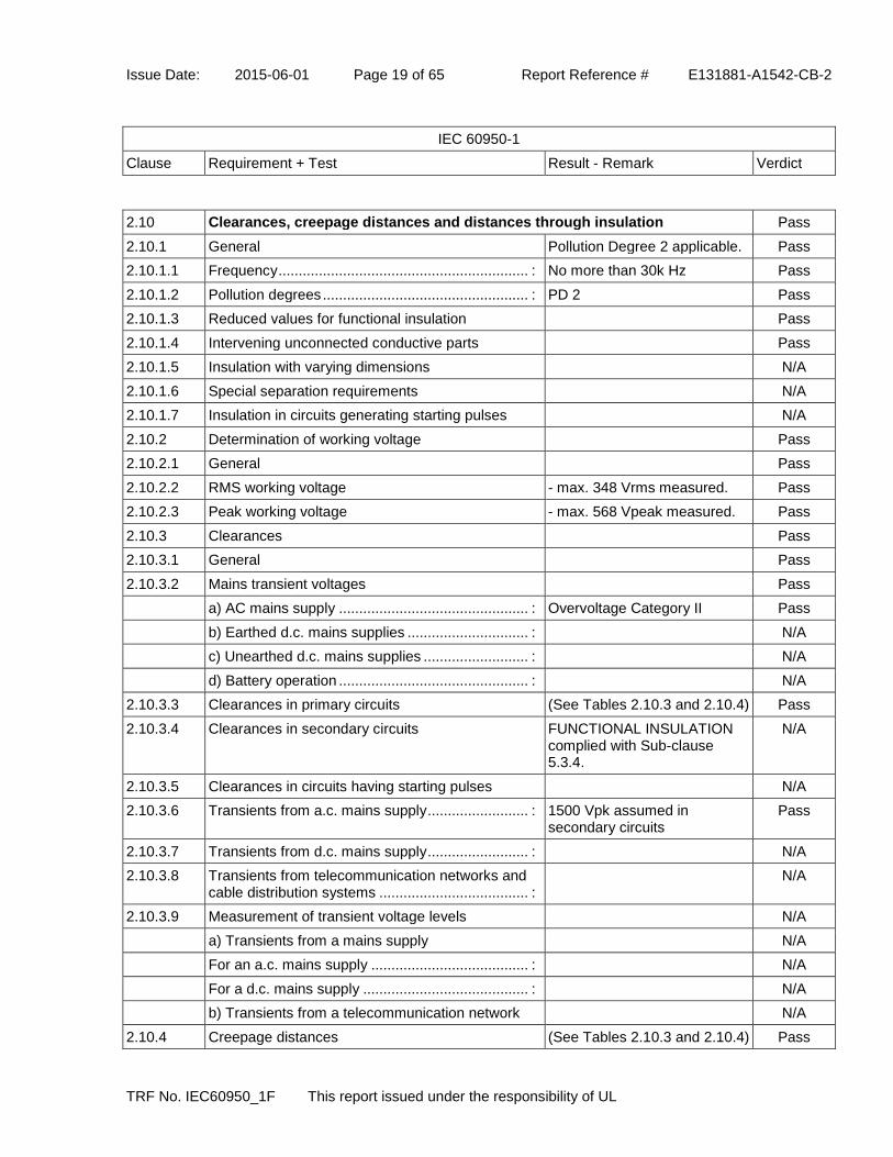
2.10 Clearances, creepage distances and distances through insulation Pass
2.10.1 General Pollution Degree 2 applicable. Pass
2.10.1.1 Frequency .............................................................. : No more than 30k Hz Pass
2.10.1.2 Pollution degrees ................................................... : PD 2 Pass
2.10.1.3 Reduced values for functional insulation Pass
2.10.1.4 Intervening unconnected conductive parts Pass
2.10.1.5 Insulation with varying dimensions N/A
2.10.1.6 Special separation requirements N/A
2.10.1.7 Insulation in circuits generating starting pulses N/A
2.10.2 Determination of working voltage Pass
2.10.2.1 General Pass
2.10.2.2 RMS working voltage - max. 348 Vrms measured. Pass
2.10.2.3 Peak working voltage - max. 568 Vpeak measured. Pass
2.10.3 Clearances Pass
2.10.3.1 General Pass
2.10.3.2 Mains transient voltages Pass
a) AC mains supply ............................................... : Overvoltage Category II Pass
b) Earthed d.c. mains supplies .............................. : N/A
c) Unearthed d.c. mains supplies .......................... : N/A
d) Battery operation ............................................... : N/A
2.10.3.3 Clearances in primary circuits (See Tables 2.10.3 and 2.10.4) Pass
2.10.3.4 Clearances in secondary circuits FUNCTIONAL INSULATION complied with Sub-clause 5.3.4.
N/A
2.10.3.5 Clearances in circuits having starting pulses N/A
2.10.3.6 Transients from a.c. mains supply ......................... : 1500 Vpk assumed in secondary circuits
Pass
2.10.3.7 Transients from d.c. mains supply ......................... : N/A
2.10.3.8 Transients from telecommunication networks and cable distribution systems ..................................... :
N/A
2.10.3.9 Measurement of transient voltage levels N/A
a) Transients from a mains supply N/A
For an a.c. mains supply ....................................... : N/A
For a d.c. mains supply ......................................... : N/A
b) Transients from a telecommunication network N/A
2.10.4 Creepage distances (See Tables 2.10.3 and 2.10.4) Pass

Issue Date: 2015-06-01 Page 20 of 65 Report Reference # E131881-A1542-CB-2
IEC 60950-1
Clause Requirement + Test Result - Remark Verdict
TRF No. IEC60950_1F This report issued under the responsibility of UL
2.10.4.1 General Pass
2.10.4.2 Material group and comparative tracking index Pass
CTI tests ................................................................ : Material group IIIb; 100 <= CTI < 175.
-
2.10.4.3 Minimum creepage distances Pass
2.10.5 Solid insulation Solid or laminated insulating materials having adequate thickness are provided.
Pass
2.10.5.1 General Pass
2.10.5.2 Distances through insulation (see appended table 2.10.5) Pass
2.10.5.3 Insulating compound as solid insulation N/A
2.10.5.4 Semiconductor devices Optocoupler is an approved component. Conducted test in 2.10.11.
Pass
2.10.5.5 Cemented joints N/A
2.10.5.6 Thin sheet material - General Pass
2.10.5.7 Separable thin sheet material Pass
Number of layers (pcs) .......................................... : Minimum 2 layers -
2.10.5.8 Non-separable thin sheet material N/A
2.10.5.9 Thin sheet material - standard test procedure N/A
Electric strength test .............................................. : -
2.10.5.10 Thin sheet material - alternative test procedure Electric strength test was applied to separate layer
Pass
Electric strength test .............................................. : See table 2.10.5 -
2.10.5.11 Insulation in wound components Pass
2.10.5.12 Wire in wound components Pass
Working voltage ..................................................... : PEAK WORKING VOLTAGE exceeds 71 V.
Pass
a) Basic insulation not under stress ...................... : N/A
b) Basic, supplementary, reinforced insulation...... : Reinforced Pass
c) Compliance with Annex U ................................. : UL R/C triple insulated wire Pass
Two wires in contact inside wound component; angle between 45° and 90° ................................... :
Physical separation in the form of insulating sheet material to relieve mechanical stress at the crossover point.
Pass
2.10.5.13 Wire with solvent-based enamel in wound components
N/A

Issue Date: 2015-06-01 Page 21 of 65 Report Reference # E131881-A1542-CB-2
IEC 60950-1
Clause Requirement + Test Result - Remark Verdict
TRF No. IEC60950_1F This report issued under the responsibility of UL
Electric strength test .............................................. : -
Routine test N/A
2.10.5.14 Additional insulation in wound components N/A
Working voltage ..................................................... : N/A
- Basic insulation not under stress ........................ : N/A
- Supplementary, reinforced insulation .................. : N/A
2.10.6 Construction of printed boards Pass
2.10.6.1 Uncoated printed boards Pass
2.10.6.2 Coated printed boards N/A
2.10.6.3 Insulation between conductors on the same inner surface of a printed board
N/A
2.10.6.4 Insulation between conductors on different layers of a printed board
Single layer PCB used. N/A
Distance through insulation N/A
Number of insulation layers (pcs) .......................... : N/A
2.10.7 Component external terminations N/A
2.10.8 Tests on coated printed boards and coated components
N/A
2.10.8.1 Sample preparation and preliminary inspection N/A
2.10.8.2 Thermal conditioning N/A
2.10.8.3 Electric strength test N/A
2.10.8.4 Abrasion resistance test N/A
2.10.9 Thermal cycling See clause 2.10.11 for details. T1 was 115 degree C.
Pass
2.10.10 Test for Pollution Degree 1 environment and insulating compound
N/A
2.10.11 Tests for semiconductor devices and cemented joints
10 cycles of 2.10.9 was conducted for three samples of each optical isolator. One sample was hi-potted 4,800Vac after the last period at 115 degree C. The other two samples was hi-potted 4,800Vac after total ten cycles thermal cycling and 120 hours or 48 hours humidity test at 95% relative humidity and
Pass

Issue Date: 2015-06-01 Page 22 of 65 Report Reference # E131881-A1542-CB-2
IEC 60950-1
Clause Requirement + Test Result - Remark Verdict
TRF No. IEC60950_1F This report issued under the responsibility of UL
40 degree C. See table 1.5.1 for details.
2.10.12 Enclosed and sealed parts N/A
3 WIRING, CONNECTIONS AND SUPPLY Pass
3.1 General Pass
3.1.1 Current rating and overcurrent protection Pass
3.1.2 Protection against mechanical damage The wires are routed away from sharp edges and parts which could damage insulation.
Pass
3.1.3 Securing of internal wiring Pass
3.1.4 Insulation of conductors The insulation of the individual conductors is suitable for the application and the working voltage.
Pass
3.1.5 Beads and ceramic insulators N/A
3.1.6 Screws for electrical contact pressure N/A
3.1.7 Insulating materials in electrical connections N/A
3.1.8 Self-tapping and spaced thread screws N/A
3.1.9 Termination of conductors Pass
10 N pull test With applying a pull force of 10 N, the conductor does not break away or pivot on its terminal to the extent that required CLEARANCE or CREEPAGE DISTANCES are reduced below the values required in 2.10.
Pass
3.1.10 Sleeving on wiring The sleeving used as reinforced insulation on internal wiring is retained by positive means. (FG wire)
Pass

Issue Date: 2015-06-01 Page 23 of 65 Report Reference # E131881-A1542-CB-2
IEC 60950-1
Clause Requirement + Test Result - Remark Verdict
TRF No. IEC60950_1F This report issued under the responsibility of UL
3.2 Connection to mains supply Pass
3.2.1 Means of connection The unit is provided with an appliance inlet.
Pass
3.2.1.1 Connection to an a.c. mains supply Pass
3.2.1.2 Connection to a d.c. mains supply N/A
3.2.2 Multiple supply connections N/A
3.2.3 Permanently connected equipment N/A
Number of conductors, diameter of cable and conduits (mm) ........................................................ :
-
3.2.4 Appliance inlets Approved appliance inlet complying with IEC 60320 and UL 498, so placed that the connector can be inserted without difficulty and after insertion of the connector, the equipment is not supported by the connector for any position of normal use on a flat surface.
Pass
3.2.5 Power supply cords Power supply cord suitable for application and subject to country's national code and regulations to be provided by the manufacturer.
Pass
3.2.5.1 AC power supply cords Pass
Type ....................................................................... : See table 1.5.1. -
Rated current (A), cross-sectional area (mm²), AWG ...................................................................... :
See table 1.5.1. -
3.2.5.2 DC power supply cords N/A
3.2.6 Cord anchorages and strain relief For Output Cord Pass
Mass of equipment (kg), pull (N) ........................... : 0.44kg, 30N for interconnecting cable
-
Longitudinal displacement (mm) ........................... : maximum 0.002mm -
3.2.7 Protection against mechanical damage N/A
3.2.8 Cord guards N/A
Diameter of minor dimension D (mm); test mass (g) ............................................................................... :
-
Radius of curvature of cord (mm) .......................... : -
3.2.9 Supply wiring space N/A

Issue Date: 2015-06-01 Page 24 of 65 Report Reference # E131881-A1542-CB-2
IEC 60950-1
Clause Requirement + Test Result - Remark Verdict
TRF No. IEC60950_1F This report issued under the responsibility of UL
3.3 Wiring terminals for connection of external conductors N/A
3.3.1 Wiring terminals N/A
3.3.2 Connection of non-detachable power supply cords N/A
3.3.3 Screw terminals N/A
3.3.4 Conductor sizes to be connected N/A
Rated current (A), cord/cable type, cross-sectional area (mm²) ............................................................. :
-
3.3.5 Wiring terminal sizes N/A
Rated current (A), type and nominal thread diameter (mm) ....................................................... :
-
3.3.6 Wiring terminals design N/A
3.3.7 Grouping of wiring terminals N/A
3.3.8 Stranded wire N/A
3.4 Disconnection from the mains supply Pass
3.4.1 General requirement Pass
3.4.2 Disconnect devices The equipment is provided with an appliance coupler.
Pass
3.4.3 Permanently connected equipment N/A
3.4.4 Parts which remain energized N/A
3.4.5 Switches in flexible cords N/A
3.4.6 Number of poles - single-phase and d.c. equipment Disconnect device disconnects all poles simultaneously.
Pass
3.4.7 Number of poles - three-phase equipment N/A
3.4.8 Switches as disconnect devices N/A
3.4.9 Plugs as disconnect devices N/A
3.4.10 Interconnected equipment N/A
3.4.11 Multiple power sources N/A

Issue Date: 2015-06-01 Page 25 of 65 Report Reference # E131881-A1542-CB-2
IEC 60950-1
Clause Requirement + Test Result - Remark Verdict
TRF No. IEC60950_1F This report issued under the responsibility of UL
3.5 Interconnection of equipment Pass
3.5.1 General requirements Interconnection circuit did continued conformance to the requirements of SELV CIRCUITS.
Pass
3.5.2 Types of interconnection circuits ........................... : SELV CIRCUITS are only connected to SELV CIRCUITS or LIMITED CURRENT CIRCUITS.
Pass
3.5.3 ELV circuits as interconnection circuits N/A
3.5.4 Data ports for additional equipment N/A
4 PHYSICAL REQUIREMENTS Pass
4.1 Stability N/A
Angle of 10° N/A
Test force (N) ......................................................... : N/A
4.2 Mechanical strength Pass
4.2.1 General Pass
Rack-mounted equipment N/A
4.2.2 Steady force test, 10 N Pass
4.2.3 Steady force test, 30 N N/A
4.2.4 Steady force test, 250 N No hazards as a result of the 250 N test.
Pass
4.2.5 Impact test Pass
Fall test No hazards as a result during the test.
Pass
Swing test N/A
4.2.6 Drop test; height (mm) ........................................... : No hazards as a result of the drop test.
Pass
4.2.7 Stress relief test No indication of shrinkage or distortion on all sources of enclosures due to the stress relief test (102 degree C/7 h).
Pass
4.2.8 Cathode ray tubes N/A
Picture tube separately certified ............................ : N/A
4.2.9 High pressure lamps N/A
4.2.10 Wall or ceiling mounted equipment; force (N) ....... : N/A

Issue Date: 2015-06-01 Page 26 of 65 Report Reference # E131881-A1542-CB-2
IEC 60950-1
Clause Requirement + Test Result - Remark Verdict
TRF No. IEC60950_1F This report issued under the responsibility of UL
4.3 Design and construction Pass
4.3.1 Edges and corners All edges and corners judged to be sufficiently well rounded so as not to constitute a hazard.
Pass
4.3.2 Handles and manual controls; force (N) ................ : N/A
4.3.3 Adjustable controls N/A
4.3.4 Securing of parts No loosening of parts impairing creepage distances or clearances over supplementary or reinforced insulation is likely to occur.
Pass
4.3.5 Connection by plugs and sockets N/A
4.3.6 Direct plug-in equipment N/A
Torque ................................................................... : N/A
Compliance with the relevant mains plug standard: N/A
4.3.7 Heating elements in earthed equipment N/A
4.3.8 Batteries N/A
- Overcharging of a rechargeable battery N/A
- Unintentional charging of a non-rechargeable battery
N/A
- Reverse charging of a rechargeable battery N/A
- Excessive discharging rate for any battery N/A
4.3.9 Oil and grease N/A
4.3.10 Dust, powders, liquids and gases N/A
4.3.11 Containers for liquids or gases N/A
4.3.12 Flammable liquids .................................................. : N/A
Quantity of liquid (l) ................................................ : N/A
Flash point (°C) ...................................................... : N/A
4.3.13 Radiation N/A
4.3.13.1 General N/A
4.3.13.2 Ionizing radiation N/A
Measured radiation (pA/kg) ................................... : -
Measured high-voltage (kV) .................................. : -
Measured focus voltage (kV) ................................. : -
CRT markings ........................................................ : -
4.3.13.3 Effect of ultraviolet (UV) radiation on materials N/A

Issue Date: 2015-06-01 Page 27 of 65 Report Reference # E131881-A1542-CB-2
IEC 60950-1
Clause Requirement + Test Result - Remark Verdict
TRF No. IEC60950_1F This report issued under the responsibility of UL
Part, property, retention after test, flammability classification .......................................................... :
N/A
4.3.13.4 Human exposure to ultraviolet (UV) radiation ....... : N/A
4.3.13.5 Lasers (including laser diodes) and LEDs N/A
4.3.13.5.1 Lasers (including laser diodes) N/A
Laser class ............................................................ : -
4.3.13.5.2 Light emitting diodes (LEDs) N/A
4.3.13.6 Other types ............................................................ : N/A
4.4 Protection against hazardous moving parts N/A
4.4.1 General No hazardous moving part presents.
N/A
4.4.2 Protection in operator access areas ...................... : N/A
Household and home/office document/media shredders
N/A
4.4.3 Protection in restricted access locations ............... : N/A
4.4.4 Protection in service access areas N/A
4.4.5 Protection against moving fan blades N/A
4.4.5.1 General N/A
Not considered to cause pain or injury. a) ............. : N/A
Is considered to cause pain, not injury. b) ............. : N/A
Considered to cause injury. c) ............................... : N/A
4.4.5.2 Protection for users N/A
Use of symbol or warning ...................................... : N/A
4.4.5.3 Protection for service persons N/A
Use of symbol or warning ...................................... : N/A

Issue Date: 2015-06-01 Page 28 of 65 Report Reference # E131881-A1542-CB-2
IEC 60950-1
Clause Requirement + Test Result - Remark Verdict
TRF No. IEC60950_1F This report issued under the responsibility of UL
4.5 Thermal requirements Pass
4.5.1 General Pass
4.5.2 Temperature tests (see appended table 4.5) Pass
Normal load condition per Annex L ....................... : Operated in the most unfavorable way of operation given in the operating instructions until steady conditions established.
-
4.5.3 Temperature limits for materials Pass
4.5.4 Touch temperature limits Pass
4.5.5 Resistance to abnormal heat ................................. : See table 4.5.5 Pass
4.6 Openings in enclosures Pass
4.6.1 Top and side openings There are no openings in the top and side of the enclosure.
Pass
Dimensions (mm) .................................................. : -- -
4.6.2 Bottoms of fire enclosures No openings. Pass
Construction of the bottom, dimensions (mm)....... : -- -
4.6.3 Doors or covers in fire enclosures N/A
4.6.4 Openings in transportable equipment No openings provided. Pass
4.6.4.1 Constructional design measures Pass
Dimensions (mm) .................................................. : No openings. -
4.6.4.2 Evaluation measures for larger openings N/A
4.6.4.3 Use of metallized parts N/A
4.6.5 Adhesives for constructional purposes N/A
Conditioning temperature (°C), time (weeks) ........ : -
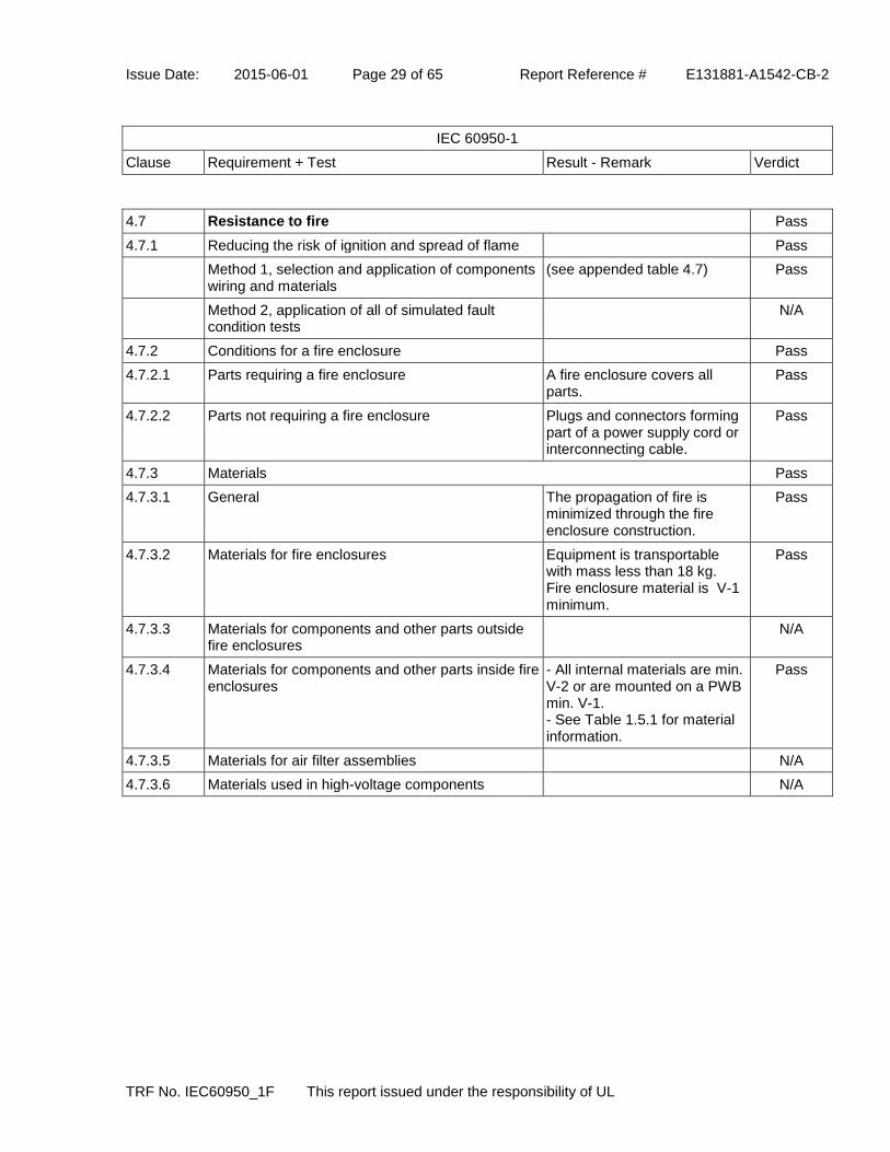
Issue Date: 2015-06-01 Page 29 of 65 Report Reference # E131881-A1542-CB-2
IEC 60950-1
Clause Requirement + Test Result - Remark Verdict
TRF No. IEC60950_1F This report issued under the responsibility of UL
4.7 Resistance to fire Pass
4.7.1 Reducing the risk of ignition and spread of flame Pass
Method 1, selection and application of components wiring and materials
(see appended table 4.7) Pass
Method 2, application of all of simulated fault condition tests
N/A
4.7.2 Conditions for a fire enclosure Pass
4.7.2.1 Parts requiring a fire enclosure A fire enclosure covers all parts.
Pass
4.7.2.2 Parts not requiring a fire enclosure Plugs and connectors forming part of a power supply cord or interconnecting cable.
Pass
4.7.3 Materials Pass
4.7.3.1 General The propagation of fire is minimized through the fire enclosure construction.
Pass
4.7.3.2 Materials for fire enclosures Equipment is transportable with mass less than 18 kg. Fire enclosure material is V-1 minimum.
Pass
4.7.3.3 Materials for components and other parts outside fire enclosures
N/A
4.7.3.4 Materials for components and other parts inside fire enclosures
- All internal materials are min. V-2 or are mounted on a PWB min. V-1. - See Table 1.5.1 for material information.
Pass
4.7.3.5 Materials for air filter assemblies N/A
4.7.3.6 Materials used in high-voltage components N/A

Issue Date: 2015-06-01 Page 30 of 65 Report Reference # E131881-A1542-CB-2
IEC 60950-1
Clause Requirement + Test Result - Remark Verdict
TRF No. IEC60950_1F This report issued under the responsibility of UL
5 ELECTRICAL REQUIREMENTS AND SIMULATED ABNORMAL CONDITIONS Pass
5.1 Touch current and protective conductor current Pass
5.1.1 General Pass
5.1.2 Configuration of equipment under test (EUT) The EUT provided only one connection to AC MAINS SUPPLY.
Pass
5.1.2.1 Single connection to an a.c. mains supply Pass
5.1.2.2 Redundant multiple connections to an a.c. mains supply
N/A
5.1.2.3 Simultaneous multiple connections to an a.c. mains supply
N/A
5.1.3 Test circuit Single phase equipment intended only for connection to star TN or TT system.
Pass
5.1.4 Application of measuring instrument Using the measuring instrument specified in annex D.1.
Pass
5.1.5 Test procedure Pass
5.1.6 Test measurements Pass
Supply voltage (V) ................................................. : 264V/60Hz -
Measured touch current (mA) ................................ : See appended table 5.1. -
Max. allowed touch current (mA) ........................... : - 0.25 mA with switch "e" closed. - 3.5 mA with switch "e" open.
-
Measured protective conductor current (mA) ........ : See appended table 5.1. -
Max. allowed protective conductor current (mA) ... : See appended table 5.1. -
5.1.7 Equipment with touch current exceeding 3,5 mA N/A
5.1.7.1 General .................................................................. : N/A
5.1.7.2 Simultaneous multiple connections to the supply N/A
5.1.8 Touch currents to telecommunication networks and cable distribution systems and from telecommunication networks
No TNV presents. N/A
5.1.8.1 Limitation of the touch current to a telecommunication network or to a cable distribution system
N/A
Supply voltage (V) ................................................. : -
Measured touch current (mA) ................................ : -
Max. allowed touch current (mA) ........................... : -
5.1.8.2 Summation of touch currents from N/A

Issue Date: 2015-06-01 Page 31 of 65 Report Reference # E131881-A1542-CB-2
IEC 60950-1
Clause Requirement + Test Result - Remark Verdict
TRF No. IEC60950_1F This report issued under the responsibility of UL
telecommunication networks
a) EUT with earthed telecommunication ports ...... : N/A
b) EUT whose telecommunication ports have no reference to protective earth
N/A
5.2 Electric strength Pass
5.2.1 General (see appended table 5.2) Pass
5.2.2 Test procedure No insulation breakdown detected during the test. (see appended table 5.2)
Pass
5.3 Abnormal operating and fault conditions Pass
5.3.1 Protection against overload and abnormal operation
(see appended table 5.3) Pass
5.3.2 Motors N/A
5.3.3 Transformers Compliance is checked by the applicable tests of Clause C.1.
Pass
5.3.4 Functional insulation .............................................. : Functional insulation complies with the requirements (c).
Pass
5.3.5 Electromechanical components N/A
5.3.6 Audio amplifiers in ITE ........................................... : N/A
5.3.7 Simulation of faults (See append table 5.3) Pass
5.3.8 Unattended equipment N/A
5.3.9 Compliance criteria for abnormal operating and fault conditions
No fire, emission of molten metal, deformation, excessive temperature rises or insulation breakdown was detected during these tests.
Pass
5.3.9.1 During the tests No fire, emission of molten metal or deformation was noted during the tests.
Pass
5.3.9.2 After the tests Electric Strength tests performed after abnormal and fault tests.
Pass

Issue Date: 2015-06-01 Page 32 of 65 Report Reference # E131881-A1542-CB-2
IEC 60950-1
Clause Requirement + Test Result - Remark Verdict
TRF No. IEC60950_1F This report issued under the responsibility of UL
6 CONNECTION TO TELECOMMUNICATION NETWORKS N/A
6.1 Protection of telecommunication network service persons, and users of other equipment connected to the network, from hazards in the equipment
N/A
6.1.1 Protection from hazardous voltages N/A
6.1.2 Separation of the telecommunication network from earth N/A
6.1.2.1 Requirements No TNV presents. N/A
Supply voltage (V) ................................................. : -
Current in the test circuit (mA) ............................... : -
6.1.2.2 Exclusions.............................................................. : N/A
6.2 Protection of equipment users from overvoltages on telecommunication networks
N/A
6.2.1 Separation requirements N/A
6.2.2 Electric strength test procedure N/A
6.2.2.1 Impulse test N/A
6.2.2.2 Steady-state test N/A
6.2.2.3 Compliance criteria N/A
6.3 Protection of the telecommunication wiring system from overheating N/A
Max. output current (A) .......................................... : -
Current limiting method ......................................... : -
7 CONNECTION TO CABLE DISTRIBUTION SYSTEMS N/A
7.1 General N/A
7.2 Protection of cable distribution system service persons, and users of other equipment connected to the system, from hazardous voltages in the equipment
N/A
7.3 Protection of equipment users from overvoltages on the cable distribution system
N/A
7.4 Insulation between primary circuits and cable distribution systems
N/A
7.4.1 General N/A
7.4.2 Voltage surge test N/A
7.4.3 Impulse test N/A

Issue Date: 2015-06-01 Page 33 of 65 Report Reference # E131881-A1542-CB-2
IEC 60950-1
Clause Requirement + Test Result - Remark Verdict
TRF No. IEC60950_1F This report issued under the responsibility of UL
A ANNEX A, TESTS FOR RESISTANCE TO HEAT AND FIRE N/A
A.1 Flammability test for fire enclosures of movable equipment having a total mass exceeding 18 kg, and of stationary equipment (see 4.7.3.2)
N/A
A.1.1 Samples ................................................................. : -
Wall thickness (mm) .............................................. : -
A.1.2 Conditioning of samples; temperature (°C) ........... : N/A
A.1.3 Mounting of samples ............................................. : N/A
A.1.4 Test flame (see IEC 60695-11-3) N/A
Flame A, B, C or D ................................................ : N/A
A.1.5 Test procedure N/A
A.1.6 Compliance criteria N/A
Sample 1 burning time (s) ..................................... : -
Sample 2 burning time (s) ..................................... : -
Sample 3 burning time (s) ..................................... : -
A.2 Flammability test for fire enclosures of movable equipment having a total mass not exceeding 18 kg, and for material and components located inside fire enclosures (see 4.7.3.2 and 4.7.3.4)
N/A
A.2.1 Samples, material .................................................. : -
Wall thickness (mm) .............................................. : -
A.2.2 Conditioning of samples; temperature (°C) ........... : N/A
A.2.3 Mounting of samples ............................................. : N/A
A.2.4 Test flame (see IEC 60695-11-4) N/A
Flame A, B or C ..................................................... : -
A.2.5 Test procedure N/A
A.2.6 Compliance criteria N/A
Sample 1 burning time (s) ..................................... : -
Sample 2 burning time (s) ..................................... : -
Sample 3 burning time (s) ..................................... : -
A.2.7 Alternative test acc. to IEC 60695-11-5, cl. 5 and 9 N/A
Sample 1 burning time (s) ..................................... : -
Sample 2 burning time (s) ..................................... : -
Sample 3 burning time (s) ..................................... : -
A.3 Hot flaming oil test (see 4.6.2) N/A
A.3.1 Mounting of samples N/A
A.3.2 Test procedure N/A

Issue Date: 2015-06-01 Page 34 of 65 Report Reference # E131881-A1542-CB-2
IEC 60950-1
Clause Requirement + Test Result - Remark Verdict
TRF No. IEC60950_1F This report issued under the responsibility of UL
A.3.3 Compliance criterion N/A
B ANNEX B, MOTOR TESTS UNDER ABNORMAL CONDITIONS (see 4.7.2.2 and 5.3.2)
N/A
B.1 General requirements N/A
Position .................................................................. : -
Manufacturer ......................................................... : -
Type ....................................................................... : -
Rated values .......................................................... : -
B.2 Test conditions N/A
B.3 Maximum temperatures N/A
B.4 Running overload test N/A
B.5 Locked-rotor overload test N/A
Test duration (days) ............................................... : -
Electric strength test: test voltage (V) .................... : -
B.6 Running overload test for d.c. motors in secondary circuits
N/A
B.6.1 General N/A
B.6.2 Test procedure N/A
B.6.3 Alternative test procedure N/A
B.6.4 Electric strength test; test voltage (V) .................... : N/A
B.7 Locked-rotor overload test for d.c. motors in secondary circuits
N/A
B.7.1 General N/A
B.7.2 Test procedure N/A
B.7.3 Alternative test procedure N/A
B.7.4 Electric strength test; test voltage (V) .................... : N/A
B.8 Test for motors with capacitors N/A
B.9 Test for three-phase motors N/A
B.10 Test for series motors N/A
Operating voltage (V) ............................................ : -

Issue Date: 2015-06-01 Page 35 of 65 Report Reference # E131881-A1542-CB-2
IEC 60950-1
Clause Requirement + Test Result - Remark Verdict
TRF No. IEC60950_1F This report issued under the responsibility of UL
C ANNEX C, TRANSFORMERS (see 1.5.4 and 5.3.3) Pass
Position .................................................................. : T1 -
Manufacturer ......................................................... : (See Table 1.5.1) -
Type ....................................................................... : (See Table 1.5.1) -
Rated values .......................................................... : (See Table 1.5.1) -
Method of protection .............................................. : Internal protection. -
C.1 Overload test The temperatures on the windings did not exceed 175 degree C for a Class B system without triggering the protection device (F1).
Pass
C.2 Insulation (see appended table 5.2) Pass
Protection from displacement of windings ............. : Triple insulated wire used.. Pass
D ANNEX D, MEASURING INSTRUMENTS FOR TOUCH-CURRENT TESTS (see 5.1.4)
Pass
D.1 Measuring instrument Pass
D.2 Alternative measuring instrument N/A
E ANNEX E, TEMPERATURE RISE OF A WINDING (see 1.4.13) N/A
F ANNEX F, MEASUREMENT OF CLEARANCES AND CREEPAGE DISTANCES (see 2.10 and Annex G)
Pass

Issue Date: 2015-06-01 Page 36 of 65 Report Reference # E131881-A1542-CB-2
IEC 60950-1
Clause Requirement + Test Result - Remark Verdict
TRF No. IEC60950_1F This report issued under the responsibility of UL
G ANNEX G, ALTERNATIVE METHOD FOR DETERMINING MINIMUM CLEARANCES
N/A
G.1 Clearances N/A
G.1.1 General N/A
G.1.2 Summary of the procedure for determining minimum clearances
N/A
G.2 Determination of mains transient voltage (V) N/A
G.2.1 AC mains supply .................................................... : N/A
G.2.2 Earthed d.c. mains supply ..................................... : N/A
G.2.3 Unearthed d.c. mains supply ................................. : N/A
G.2.4 Battery operation ................................................... : N/A
G.3 Determination of telecommunication network transient voltage (V) :
N/A
G.4 Determination of required withstand voltage (V) N/A
G.4.1 Mains transients and internal repetitive peaks ...... : N/A
G.4.2 Transients from telecommunication networks ....... : N/A
G.4.3 Combination of transients N/A
G.4.4 Transients from cable distribution systems N/A
G.5 Measurement of transient voltages (V) N/A
a) Transients from a mains supply N/A
For an a.c. mains supply N/A
For a d.c. mains supply N/A
b) Transients from a telecommunication network N/A
G.6 Determination of minimum clearances N/A
H ANNEX H, IONIZING RADIATION (see 4.3.13) N/A
J ANNEX J, TABLE OF ELECTROCHEMICAL POTENTIALS (see 2.6.5.6) N/A
Metal(s) used ......................................................... : -

Issue Date: 2015-06-01 Page 37 of 65 Report Reference # E131881-A1542-CB-2
IEC 60950-1
Clause Requirement + Test Result - Remark Verdict
TRF No. IEC60950_1F This report issued under the responsibility of UL
K ANNEX K, THERMAL CONTROLS (see 1.5.3 and 5.3.8) N/A
K.1 Making and breaking capacity N/A
K.2 Thermostat reliability; operating voltage (V) .......... : N/A
K.3 Thermostat endurance test; operating voltage (V) : N/A
K.4 Temperature limiter endurance; operating voltage (V) .......................................................................... :
N/A
K.5 Thermal cut-out reliability N/A
K.6 Stability of operation N/A
L ANNEX L, NORMAL LOAD CONDITIONS FOR SOME TYPES OF ELECTRICAL BUSINESS EQUIPMENT (see 1.2.2.1 and 4.5.2)
Pass
L.1 Typewriters N/A
L.2 Adding machines and cash registers N/A
L.3 Erasers N/A
L.4 Pencil sharpeners N/A
L.5 Duplicators and copy machines N/A
L.6 Motor-operated files N/A
L.7 Other business equipment Pass
M ANNEX M, CRITERIA FOR TELEPHONE RINGING SIGNALS (see 2.3.1) N/A
M.1 Introduction N/A
M.2 Method A N/A
M.3 Method B N/A
M.3.1 Ringing signal N/A
M.3.1.1 Frequency (Hz) ...................................................... : -
M.3.1.2 Voltage (V) ............................................................. : -
M.3.1.3 Cadence; time (s), voltage (V) ............................... : -
M.3.1.4 Single fault current (mA) ........................................ : -
M.3.2 Tripping device and monitoring voltage ................. : N/A
M.3.2.1 Conditions for use of a tripping device or a monitoring voltage
N/A
M.3.2.2 Tripping device N/A
M.3.2.3 Monitoring voltage (V) ........................................... : N/A

Issue Date: 2015-06-01 Page 38 of 65 Report Reference # E131881-A1542-CB-2
IEC 60950-1
Clause Requirement + Test Result - Remark Verdict
TRF No. IEC60950_1F This report issued under the responsibility of UL
N ANNEX N, IMPULSE TEST GENERATORS (see 1.5.7.2, 1.5.7.3, 2.10.3.9, 6.2.2.1, 7.3.2, 7.4.3 and Clause G.5)
N/A
N.1 ITU-T impulse test generators N/A
N.2 IEC 60065 impulse test generator N/A
P ANNEX P, NORMATIVE REFERENCES Pass
Q ANNEX Q, Voltage dependent resistors (VDRs) (see 1.5.9.1) N/A
- Preferred climatic categories ............................... : N/A
- Maximum continuous voltage .............................. : N/A
- Combination Pulse current .................................. : N/A
Body of the VDR Test according to IEC60695-11-5 ............................................................................... :
N/A
Body of the VDR. Flammability class of material ( min V-1) ................................................................. :
N/A
R ANNEX R, EXAMPLES OF REQUIREMENTS FOR QUALITY CONTROL PROGRAMMES
N/A
R.1 Minimum separation distances for unpopulated coated printed boards (see 2.10.6.2)
N/A
R.2 Reduced clearances (see 2.10.3) N/A
S ANNEX S, PROCEDURE FOR IMPULSE TESTING (see 6.2.2.3) N/A
S.1 Test equipment N/A
S.2 Test procedure N/A
S.3 Examples of waveforms during impulse testing N/A
T ANNEX T, GUIDANCE ON PROTECTION AGAINST INGRESS OF WATER (see 1.1.2)
N/A
............................................................................... : -
U ANNEX U, INSULATED WINDING WIRES FOR USE WITHOUT INTERLEAVED INSULATION (see 2.10.5.4)
Pass
............................................................................... : UL Approved triple insulated wire used.
-

Issue Date: 2015-06-01 Page 39 of 65 Report Reference # E131881-A1542-CB-2
IEC 60950-1
Clause Requirement + Test Result - Remark Verdict
TRF No. IEC60950_1F This report issued under the responsibility of UL
V ANNEX V, AC POWER DISTRIBUTION SYSTEMS (see 1.6.1) Pass
V.1 Introduction Pass
V.2 TN power distribution systems Pass
W ANNEX W, SUMMATION OF TOUCH CURRENTS N/A
W.1 Touch current from electronic circuits N/A
W.1.1 Floating circuits N/A
W.1.2 Earthed circuits N/A
W.2 Interconnection of several equipments N/A
W.2.1 Isolation N/A
W.2.2 Common return, isolated from earth N/A
W.2.3 Common return, connected to protective earth N/A
X ANNEX X, MAXIMUM HEATING EFFECT IN TRANSFORMER TESTS (see clause C.1)
N/A
X.1 Determination of maximum input current N/A
X.2 Overload test procedure N/A
Y ANNEX Y, ULTRAVIOLET LIGHT CONDITIONING TEST (see 4.3.13.3) N/A
Y.1 Test apparatus ....................................................... : N/A
Y.2 Mounting of test samples ....................................... : N/A
Y.3 Carbon-arc light-exposure apparatus .................... : N/A
Y.4 Xenon-arc light-exposure apparatus ..................... : N/A
Z ANNEX Z, OVERVOLTAGE CATEGORIES (see 2.10.3.2 and Clause G.2) Pass
AA ANNEX AA, MANDREL TEST (see 2.10.5.8) N/A
BB ANNEX BB, CHANGES IN THE SECOND EDITION Pass

Issue Date: 2015-06-01 Page 40 of 65 Report Reference # E131881-A1542-CB-2
IEC 60950-1
Clause Requirement + Test Result - Remark Verdict
TRF No. IEC60950_1F This report issued under the responsibility of UL
CC ANNEX CC, EVALUATION OF INTEGRATED CIRCUIT (IC) CURRENT LIMITERS
N/A
CC.1 General N/A
CC.2 Test program 1 ...................................................... : N/A
CC.3 Test program 2 ...................................................... : N/A
CC.4 Test program 3 ...................................................... : N/A
CC.5 Compliance ............................................................ : N/A
DD ANNEX DD, REQUIREMENTS FOR THE MOUNTING MEANS OF RACK-MOUNTED EQUIPMENT
N/A
DD.1 General N/A
DD.2 Mechanical strength test, variable N ..................... : N/A
DD.3 Mechanical strength test, 250 N, including end stops ...................................................................... :
N/A
DD.4 Compliance ............................................................ : N/A
EE ANNEX EE, HOUSEHOLD AND HOME/OFFICE DOCUMENT/MEDIA SHREDDERS
N/A
EE.1 General N/A
EE.2 Markings and instructions N/A
Use of markings or symbols .................................. : N/A
Information of user instructions, maintenance and/or servicing instructions .................................. :
N/A
EE.3 Inadvertent reactivation test .................................. : N/A
EE.4 Disconnection of power to hazardous moving parts N/A
Use of markings or symbols .................................. : N/A
EE.5 Protection against hazardous moving parts .......... : N/A
Test with test finger (Figure 2A) N/A
Test with wedge probe (Figure EE1 and EE2) ...... : N/A

Issue Date: 2015-06-01 Page 41 of 65 Report Reference # E131881-A1542-CB-2
IEC 60950-1
Clause Requirement + Test Result - Remark Verdict
TRF No. IEC60950_1F This report issued under the responsibility of UL
1.5.1 TABLE: list of critical components Pass
object/part or Description
manufacturer/ trademark
type/model technical data standard (Edition or year)
mark(s) of conformity
1)
1. Appliance Inlet DELTA ELECTRONICS, INC.
SK-1024M 2.5A, 250Vac, 70 degree C
IEC/EN 60320-1, UL 498, GB17465.1-2009
UL, TUV, CCC, FI
2. Fuse (F1) LITTELFUSE WICKMANN WERKE (for UL) Littelfuse, Inc. (for VDE), LITTELFUSE PHILIPPINES INC. (for CQC)
392 T3.15AL, 250Vac
EN 60127-3, EN60127-1, UL 248-1, UL 248-14, GB9364.1-1997 GB9364.3-1997 CQC/RY131-2003 appendix 2
UL, VDE, CQC
2a. Fuse (F1) (Alternate)
EVER ISLAND ELECTRIC CO LTD & WALTER ELECTRIC, Suzhou Walter Electronic Co., Ltd. (for CQC) Dongguan Walter Electric Co., Ltd(CQC)
2010 T3.15AL, 250Vac
IEC/EN 60127-2, IEC/EN60127-1, ANSI/UL248-1, ANSI/UL248-14, GB9364.1-1997 GB9364.2-1997,
UL, VDE, CCC
2b. Fuse (F1) (Alternate)
BEL FUSE INC (for UL) Bel Fuse Ltd. (for VDE and CCC)
RST T3.15AL, 2 50Vac(ccc and VDE), 277 Vac(for UL)
UL248-1, UL248-14,GB9364.1-1997 GB9364.2-1997,IEC/EN 60127-1, IEC/EN 60127-3,
UL, CCC,VDE
2c. Fuse (F1) (Alternate)
Conquer Electronics Co., Ltd.
MST T3.15AL, 250V (for VDE, CQC, UL), 300V (for UL)
IEC/EN 60127-1, IEC/EN 60127-3, UL 248-14, GB9364.1-1997 GB9364.3-1997 CQC11-462125-2009 appendix 2
UL, VDE,CQC
2d. Fuse (F1) (Alternate)
Hollyland Co 5ET T3.15AL, 250Vac
IEC/EN 60127-1, IEC/EN 60127-3, UL248-1, UL248-14, CSA-C22.2 No. 248-1-00, CSA-C22.2 No. 248-14-00, GB9364.1-1997 GB9364.2-1997
UL, CQC, VDE
3. Bleeder Resistors (R1,
Interchangeable Interchangeable Connected in series, each 2M
-- --, --

Issue Date: 2015-06-01 Page 42 of 65 Report Reference # E131881-A1542-CB-2
IEC 60950-1
Clause Requirement + Test Result - Remark Verdict
TRF No. IEC60950_1F This report issued under the responsibility of UL
R2) ohm, 1/4 W.
4. Capacitor (C1) Interchangeable Interchangeable 120uF, min. 420V , 105 Degree C
-- --, --
5. X-Capacitor (CX1 ) (Alternate)
KEMET ELECTRONICS ITALIA SRL (for UL), KEMET ELECTRONICS CORPORATION (for IMQ), 1.ARCOTRONICS ITALIA S.P.A (for CQC), 2.3. ARCOTRONICS Industries S.r.l (for CQC)
R.46 0.33uF, 275Vac (For ENEC), 250Vac (For UL) 110 degree C, X2 type, Comply with IEC 60384-14
IEC60384-14: 2005, EN 60384 -14: 2005, UL 1414, GB/T14472-1998;
UL, ENEC 03, CQC
5a. X-Capacitor (CX1 ) (Alternate)
Hua JungComponents Co.,Ltd
MKP 0.33uF 250Vac,110 degree C, X2 type, Comply with IEC 60384-14
IEC60384-14: 2005, EN 60384 -14: 2005, UL 1414, GB/T14472-1998;
UL, VDE;CQC; CSA
5b. X-Capacitor (CX1 ) (Alternate)
Europtronic (Taiwan) Ind. Corp. (for ENEC, VDE and CQC) EUROPTRONIC (TAIWAN) INDUSTRIAL CORP (for UL)
MPX2 0.33uF, 275 Vac or 305 Vac (For ENEC and VDE ), 250Vac or 275Vac (for UL) 110 degree C, X2 type, Comply with IEC 60384-14
IEC60384-14: 2005, EN 60384 -14: 2005, UL 1414, GB/T14472-1998;
UL, ENEC 10, VDE, CQC
5c. X-Capacitor (CX1 ) (Alternate)
Pilkor Electronics Co Ltd
PCX2 339 0.33uF, 305Vac, 110 degree C, X2 type. Comply with IEC60384-14.
IEC60384-14: 2005, EN 60384 -14: 2005, UL 1414, GB/T14472-1998;
UL, ENEC, IL
5d. X-Capacitor (CX1 ) (Alternate)
Epcos Electronic Components S A
B3292x-x3xxx(UL), B3292#(VDE, CQC)
0.33uF, 250Vac(UL), 305Vac(VDE, CQC), 110 degree C, X2 type. Comply with IEC60384-14. Comply with IEC60384-14.
IEC60384-14: 2005, EN 60384 -14: 2005, UL 1414, GB/T14472-1998;
UL, VDE, CQC
5e. X-Capacitor ZhuHai Sung Ho CMPP 0.33uF; IEC60384-14: UL, UL, VDE,

Issue Date: 2015-06-01 Page 43 of 65 Report Reference # E131881-A1542-CB-2
IEC 60950-1
Clause Requirement + Test Result - Remark Verdict
TRF No. IEC60950_1F This report issued under the responsibility of UL
(CX1 ) (Alternate)
Electronics Co.
Ltd.,(CQC: 威海
汉城成镐电子有
限公司; 珠海成镐
电子有限公司 )
275Vac/310Vac, 105 degree C; X2 type, Comply with IEC 60384-14
2005, EN 60384 -14: 2005, UL 1414, GB/T14472-1998;
CQC
6. Y-Capacitors (CY1, CY2 ) (CY2 only For Construction A)
Murata Mfg. Co., Ltd. (for VDE, UL) Murata Manufacturing Co., Ltd. (for CQC)
KX CY1=680pF,CY2=22pF max., 250Vac (for UL and CQC, Y1 type ), 300Vac (for VDE, Y1 Cap), 440Vac (for VDE and CQC, X1 Cap), Y1 type and X1 type, 125 degree C.
IEC60384-14: 2005, EN 60384 -14: 2005, UL 1414, GB/T14472-1998;
UL, VDE, CQC
6a.Y-Capacitors (CY1, CY2) (Alternate) (CY2 only For Construction A)
Walsin Technology Corp. (for UL and VDE) Walsin Technology Corporation (for CQC)
AH CY1=680pF,CY2=22pF max, 250Vac (for UL, VDE and CQC, Y1 & X1 Cap), 400Vac (for VDE and CQC, Y1 & X1 Cap), Y1 type and X1 type, 125 degree C.
IEC60384-14: 2005, EN 60384 -14: 2005, UL 1414, GB/T14472-1998;
UL, VDE, CQC
6b.Y-Capacitors (CY1, CY2 ) (Alternate) (CY2 only For Construction A)
TDK-EPC Corporation (for VDE); TDK-EPC CORP (for UL); TDK XIAMEN CO., LTD (for CQC); TDK-EPC Corporation (for CQC)
CD CY1=680pF,CY2=22pF max., 250Vac (for UL, VDE and CQC, Y1 & X1 Cap), 400Vac (for VDE and CQC, X1 Cap), Y1 type and X1 type, 125 degree C.
IEC60384-14: 2005, EN 60384 -14: 2005, UL 1414, GB/T14472-1998;
UL, VDE, CQC
7.Line Filter (FL1) (Only for Construction A)
Interchangeable Interchangeable 130 degree C. Refer to enclosure 4-01 for details.
-- --, --
7-1.Line Filter (FL1) (Only for Construction B)
Interchangeable Interchangeable 130 degree C. Refer to enclosure 4-16 for details.
-- --, --
8.Line Filter (FL2) (Only for Construction A)
Interchangeable Interchangeable 130 degree C. Refer to enclosure 4-02 for details.
-- --, --

Issue Date: 2015-06-01 Page 44 of 65 Report Reference # E131881-A1542-CB-2
IEC 60950-1
Clause Requirement + Test Result - Remark Verdict
TRF No. IEC60950_1F This report issued under the responsibility of UL
8.Line Filter (FL2) (Only for Construction B)
Interchangeable Interchangeable 130 degree C. Refer to enclosure 4-17 for details.
-- --, --
9.Line Filter (L1) Interchangeable Interchangeable 130 degree C. Refer to enclosure 4-03 for details.
-- --, --
10.Line Filter (L2) (Only for Construction A)
Interchangeable Interchangeable 130 degree C. Refer to enclosure 4-04 for details.
-- --, --
10.Line Filter (L2) (Only for Construction B)
Interchangeable Interchangeable 130 degree C. Refer to enclosure 4-18 for details.
-- --, --
11. MOSFET (Q1 ) (Only for Construction A)
Interchangeable Interchangeable 600V-650, 10.6-17A
-- --, --
11-1. MOSFET (Q3, Q4 ) (Only for Construction B)
Interchangeable Interchangeable 600V, 7~8.1A -- --, --
12. Optocoupler (For Construction A, IC35) (For Construction B, IC51, IC52)
Renesas Electronics Corporation (for UL,VDE,S)
PS2561DL-1, PS2561DL-1xx(for CCC)
dti.>0.4 mm, ext. cr.>7.0mm, Int. cr.>4.0mm, 120 hours thermal cycling test, 110 degree C, isolation: AC 4800V min. Humidify 120h.
DIN EN60747-5-2(VDE 084 Teil 2):2003-01, IEC/EN60065, IEC/EN60950-1, UL 1577, GB4943.1-2011, GB8898-2011
UL, S, VDE, CQC
12a. Optocoupler (For Construction A, IC35) (For Construction B, IC51, IC52) (Alternate)
EVERLIGHT ELECTRONICS CO LTD(For UL), Everlight Electronics Co., Ltd(for VDE,FI)
EL816 (for UL and CQC) EL816 V (for VDE) EL816.("."=A-Z or blank or number ) (for N)
dti.>0.5mm, ext. cr.>=7.6mm, int. cr.>=6.0mm, thermal cycling test ,110 degree C, isolation: AC 4800V min. Humidfy test 120h,
DIN EN60747-5-2(VDE 084 Teil 2):2003-01,IEC/EN60065, IEC/EN60950-1, IEC/EN60335-1, UL 1577, GB4943.1-2011, GB8898-2011
UL, VDE, FI, CQC,N
12b. Optocoupler (For Construction A, IC35) (For Construction B, IC51, IC52) (Alternate)
COSMO Electronics Corporation (for VDE and FI); COSMO ELECTRONICS CORP (for UL);
K1010 (for VDE, FI and CQC), K1010X-1 (for UL)
dti.>0.4mm, ext. cr.>7.0mm, int. cr.>4.0mm, 120 hours thermal cycling test, isolation: AC 4800V min, 115 degree
DIN EN60747-5-2(VDE 084 Teil 2):2003-01,EN 60950-1, EN60065, EN60335-1; UL 1577; GB4943.1-2011 GB8898-
UL, FI, VDE, CQC

Issue Date: 2015-06-01 Page 45 of 65 Report Reference # E131881-A1542-CB-2
IEC 60950-1
Clause Requirement + Test Result - Remark Verdict
TRF No. IEC60950_1F This report issued under the responsibility of UL
C,Humidify 120h. 2011
12c. Optocoupler (For Construction A, IC35) (For Construction B, IC51, IC52) (Alternate)
SHARP CORP ELECTRONIC COMPONENTS AND DEVICES GROUP (for UL ) Sharp Corporation (for VDE, S)
PC123 dti>0.4mm, ext>8.0mm,int cr.>4.0mm, 120 hours thermal cycling test, isolation: AC 5000V Min, 110 degree C, Humidify 120h.
DIN EN60747-5-2(VDE 084 Teil 2):2003-01, UL 1577, IEC/EN 60065, IEC/EN 60335-1, IEC/EN 60950-1, GB4943.1-2011, GB8898-2011
UL, VDE, S,D,CQC,FI
12d. Optocoupler (For Construction A, IC35) (For Construction B, IC51, IC52) (Alternate)
TOSHIBA CORP, SEMICONDUCTOR CO DISCRETE SEMICONDUCTOR DIV (for UL) Toshiba Corporation Semicon. Co. Discrete Div (for VDE) Toshiba Corporation Semiconductor Company (for S)
TLP781/TLP781F
dti>0.5 mm, ext. cr. > 8.0 mm, int cr. > 5.0 mm, thermal cycling tested, isolation: AC 4800V Min, 115 degree C .
DIN EN60747-5-2(VDE 084 Teil 2):2003-01, UL 1577, IEC/EN 60950-1, IEC/EN60335-1, GB4943-2001, GB8898-2001
UL, VDE, S, CQC
12e. Optocoupler (For Construction A, IC35) (For Construction B, IC51, IC52) (Alternate)
Vishay Semiconductor GMBH
VOL617AX(X=2, 3, 4)(for UL), VOL617A-X(X=2,3,4)(for CQC), VOL617A(1,2,3)X001(for VDE)
Dti.>0.4mm, external Cr>8.0mm, thermal cycling tested, 110 degree C.
DIN EN60747-5-5, VDE0884-5, EN60950-1, UL 1577, GB4943.1-2011, GB8898-2011
UL, VDE, CQC
12f. Optocoupler (For Construction A, IC35) (For Construction B, IC51, IC52) (Alternate)
Vishay Semiconductor GMBH
VOL618AX(X=2, 3, 4)(for UL), VOL618A-X(X=2,3,4)(for CQC), VOL618A(1,2,3)X001(for VDE)
Dti.>0.4mm, external Cr>8.0mm, thermal cycling tested, 110 degree C.
DIN EN60747-5-5, VDE0884-5, EN60950-1, UL 1577, GB4943.1-2011, GB8898-2011
UL, VDE, CQC
12g. Optocoupler (For Construction A, IC35) (For Construction B, IC51, IC52) (Alternate)
LITE-ON TECHNOLOGY CORP(for VDE, FI, UL, N, S), Lite-On Technology Corporation(for CQC)
LTV-816M(for UL,N,CQC),LTV-816(for VDE)
dti>0.6 mm, ext. cr.>7.0mm, int cr.>5.2mm, thermal cycling tested, isolation: min. AC 4800V, 110 degree C
DIN EN60747-5-2(VDE 0884 Teil 2)2003-01, EN 60950-1 , UL 1577 , GB4943-2011, GB8898-2011
UL, VDE,FI,UL,CQC,S
12h. Optocoupler (For
TOSHIBA CORP,
TLP785/TLP785F
dti>0.4 mm, ext. cr. > 8.0 mm, int.
DIN EN60747-5-2(VDE 084 Teil
UL, VDE, S, CQC,

Issue Date: 2015-06-01 Page 46 of 65 Report Reference # E131881-A1542-CB-2
IEC 60950-1
Clause Requirement + Test Result - Remark Verdict
TRF No. IEC60950_1F This report issued under the responsibility of UL
Construction A, IC35) (For Construction B, IC51, IC52) (Alternate)
SEMICONDUCTOR CO DISCRETE SEMICONDUCTOR DIV (for UL)
cr. > 5.0 mm, thermal cycling tested, isolation: AC 4800V Min, 115 degree C .
2):2003-01, UL 1577, IEC/EN 60950-1, IEC/EN60335-1, GB8898-2011;GB4943.1-2011
13. Thermistor (NTC31)
THINKING ELECTRONIC INDUSTRIAL CO LTD
TSM1A474 470k ohm at 25 degree C
UL 1434 UL, --
13a. Thermistor (NTC31) (Alternate)
Interchangeable interchangeable 470k ohm at 25 degree C
UL 1434 UL, --
14. Transformer (T1) (For Construction A)
Delta Electronics (Jiangsu) Co., Ltd.
MV-MP11204 Open type construction with ferrite core, see Enclosure 4-05 for detail.
Test within the unit
--, --
14a. Transformer (T1) (For Construction B)
Delta Electronics (Jiangsu) Co., Ltd.
MV-MP15038 Open type construction with ferrite core, see Enclosure 4-19 for detail.
UL1446 UL, --
14-01. Insulation System
Delta Electronics, Inc.
MP-130I Class B UL1446 UL, --
15. Plastic Enclosure
SABIC INNOVATIVE PLASTICS B V
945 V-0, 120 degree C, 2.2mm min. thickness. See Enclosure 4-06 and 4-07 for the detail shape.
UL 94 UL 746C UL, --
15a. Plastic Enclosure (Alternate)
SABIC INNOVATIVE PLASTICS JAPAN L L C
945 V-0, 120 degree C, 2.2 mm min. thickness
UL 94 UL 746C UL, --
15b. Plastic Enclosure (Alternate)
SABIC INNOVATIVE PLASTICS US L L C
945 V-0, 120 degree C, 2.2 mm min. thickness
UL 94 UL 746C UL, --
15c. Plastic Enclosure (Alternate)
BAYER MATERIALSCIENCE AG
Makrolon 6485 V-0, 115 degree C, 2.2 mm min thickness
UL 94 UL 746C UL, --
15d. Plastic Enclosure (Alternate)
TRINSEO (HONG KONG) LTD
CELEX 3600 V-0, 125 degree C, 2.2 mm min thickness
UL 94 UL 746C UL, --
15e. Plastic Enclosure (Alternate)
SAMSUNG SDI CO LTD
INFINO HN-1064I
V-0, 130 degree C 2.2 mm min
UL 94, UL 746C UL, --

Issue Date: 2015-06-01 Page 47 of 65 Report Reference # E131881-A1542-CB-2
IEC 60950-1
Clause Requirement + Test Result - Remark Verdict
TRF No. IEC60950_1F This report issued under the responsibility of UL
thickness
15f. Plastic Enclosure (Alternate)
IDEMITSU KOSAN CO LTD
AZ2201 V-0, 125 degree C, 2.2 mm min thickness
UL94,UL 746C UL, --
16. Insulation tape (for FL2)
3M COMPANY ELECTRICAL MARKETS DIV (EMD)
1350F-1 130 degree C, minimum two layers
UL510 UL, --
16a. Insulation tape (for FL2) (Alternate)
3M COMPANY ELECTRICAL MARKETS DIV (EMD)
1350T-3 130 degree C UL510 UL, --
16b. Insulation tape (for FL2) (Alternate)
3M Taiwan Ltd. 1388Y-1 130 degree C, minimum two layers
UL510 UL, --
17. Shield Ass'y(For Construction A)
Interchangeable Interchangeable See Enclosure 4-10 for dimension details.
-- --, --
17a. Shield Ass'y(For Construction B)
Interchangeable Interchangeable See Enclosure 4-20 for dimension details.
-- --, --
17-1.Insulator Sabic Innovative Plastics US L L C
FR25A V-0, 125 degree C, Min. 0.4 mm thick
UL 94, UL746C UL, --
17-1a. Insulator (Alternate)
Sun Delta Corp VS120 V-0, 130 degree C, min. 0.4 mm thick,
UL 94, UL746C UL, --
17-1 b. Insulator (Alternate)
Sun Delta Corp VS520 V-0, 130 degree C, min. 0.4 mm thick,
UL 94, UL746C UL, --
17-1c. Insulator (Alternate)
Sabic Innovative Plastics US L L C
FR1 Min. 0.4mm thickness, VTM-0, 125 degree C
UL94, UL746C UL, --
17-1d. Insulator (Alternate)
Sabic Innovative Plastics Japan L L C
FR1 Min. 0.4mm thickness, VTM-0, 125 degree C
UL94, UL746C UL, --
17-1e. Insulator (Alternate)
Sumitomo Bakelite Co Ltd
PHF150MA Min. VTM-0, 130 degree C, min. 0.40 mm thick.
UL94, UL746C UL, --
17-1f. Insulator (Alternate)
SABIC INNOVATIVE PLASTICS JAPAN L L C
FR25A V-0, 125 degree C, Min. 0.4 mm thick
UL94, UL746C UL, --
18. Shield Top(For Construction A)
Interchangeable Interchangeable See Enclosure 4-09 for dimension details.
-- --, --
18. Shield Top(For Construction B)
Interchangeable Interchangeable See Enclosure 4-21 for dimension details.
-- --, --

Issue Date: 2015-06-01 Page 48 of 65 Report Reference # E131881-A1542-CB-2
IEC 60950-1
Clause Requirement + Test Result - Remark Verdict
TRF No. IEC60950_1F This report issued under the responsibility of UL
18-1. Insulation tape
3M COMPANY ELECTRICAL MARKETS DIV (EMD)
1350F-1 130 degree C, minimum two layers
UL510 UL, --
18-1a. Insulation tape (Alternate)
3M COMPANY ELECTRICAL MARKETS DIV (EMD)
1350T-3 130 degree C, UL510 UL, --
18-1b. Insulation tape (Alternate)
3M COMPANY ELECTRICAL MARKETS DIV (EMD)
1388Y-1 130 degree C, minimum two layers
UL510 UL, --
19. Heat sink (HS1) (For Construction A)
Interchangeable Interchangeable See Enclosure 4-12 for dimension details.
-- --, --
19. Heat sink (HS1) (For Construction B)
Interchangeable Interchangeable See Enclosure 4-22 for dimension details.
-- --, --
19. Heat sink (HS2) (For Construction A)
Interchangeable Interchangeable See Enclosure 4-12 for dimension details.
-- --, --
19. Heat sink (HS2) (For Construction B)
Interchangeable Interchangeable See Enclosure 4-22 for dimension details.
-- --, --
20. Heat sink (HS3) (For Construction A)
Interchangeable Interchangeable See Enclosure 4-12 for dimension details.
-- --, --
19. Heat sink (HS3) (For Construction B)
Interchangeable Interchangeable See Enclosure 4-22 for dimension details.
-- --, --
21. Interconnecting cable
Interchangeable Interchangeable Min. 80 degree. C, 30 V, max 3.05m long, jacketed, VW-1 or FT-1, had been evaluated for external use
UL 758 UL, --
21-1. Strain Relief Means
Interchangeable Interchangeable PVC plastic bushing integrally molded on Output Cord.
UL94 UL, --
22. PWB Interchangeable Interchangeable Rated V-0, 130 degree C,
UL 796 UL, --
23. Internal Wiring
Interchangeable Interchangeable FEP, PTFE, PVC, TFE, neoprene, polyimide or marked VW-1; min 300 V, 80
UL 758 UL, --

Issue Date: 2015-06-01 Page 49 of 65 Report Reference # E131881-A1542-CB-2
IEC 60950-1
Clause Requirement + Test Result - Remark Verdict
TRF No. IEC60950_1F This report issued under the responsibility of UL
degree C, routed away from secondary (SEC, ELV, SELV) uninsulated live parts
24. Glue Interchangeable Interchangeable Min. V-2. UL 94 UL, --
25. Functional earthing Wiring
FURUKAWA ELECTRIC CO LTD
TEX-E 130 degree C UL758 UL, --
25a. Functional earthing Wiring (Alternate)
Totoku Electric Co Ltd
TIW-3(for TÜV), TIW-3X(for UL)
155 degree C UL758 UL, --
25b. Functional earthing Wiring (Alternate)
Totoku Electric Co Ltd
TIW-2(for TÜV), TIW-2X(for UL)
130 degree C UL758 UL, --
25-1.Heat Shrinkable Tubing used on FG wire
DONGGUAN SALIPT CO LTD
SALIPT S-901-600
Rating 125 degree C, VW-1, isolation: AC 3000V, min. 0.40 mm thickness
UL224 UL, --
25-1a.Heat Shrinkable Tubing used on FG wire (Alternate)
Tyco Electronics Corp (RAYCHEM)
Versafit Rating 125 degree C, VW-1, isolation: AC 3000V, min. 0.40 mm thickness
UL224 UL, --
25-1b.Heat Shrinkable Tubing used on FG wire (Alternate)
Tyco Electronics Corp (RAYCHEM)
Versafit V2 Rating 125 degree C, VW-1, isolation: AC 3000V, min. 0.40 mm thickness
UL224 UL, --
25-1c.Heat Shrinkable Tubing used on FG wire (Alternate)
WELL ONE CO LTD
GT-2 Rating 125 degree C, VW-1, isolation: AC 3000V, min. 0.44 mm thickness
UL224 UL, --
25-1d.Heat Shrinkable Tubing used on FG wire (Alternate)
Tyco Electronics Corp (RAYCHEM)
ZH2 Rating 125 degree C, VW-1, isolation: AC 3000V, min. 0.40 mm thickness
UL224 UL, --
Supplementary information: 1) Provided evidence ensures the agreed level of compliance. See OD-CB2039.
The CBTL has verified the component information.

Issue Date: 2015-06-01 Page 50 of 65 Report Reference # E131881-A1542-CB-2
IEC 60950-1
Clause Requirement + Test Result - Remark Verdict
TRF No. IEC60950_1F This report issued under the responsibility of UL
1.5.1 TABLE: Opto Electronic Devices Pass
Manufacturer -- -- --
Type -- -- --
Separately tested -- -- --
Bridging insulation -- -- --
External creepage distance
-- -- --
Internal creepage distance
-- -- --
Distance through insulation
-- -- --
Tested under the following conditions
-- -- --
Input -- -- --
Output -- -- --
-- -- -- --
supplementary information:
Recognized Optocoupler used, See critical component list.
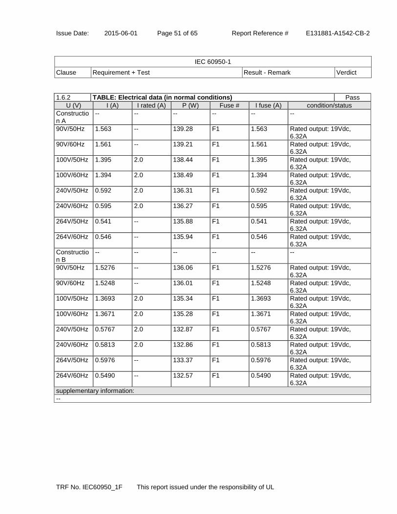
Issue Date: 2015-06-01 Page 51 of 65 Report Reference # E131881-A1542-CB-2
IEC 60950-1
Clause Requirement + Test Result - Remark Verdict
TRF No. IEC60950_1F This report issued under the responsibility of UL
1.6.2 TABLE: Electrical data (in normal conditions) Pass
U (V) I (A) I rated (A) P (W) Fuse # I fuse (A) condition/status
Construction A
-- -- -- -- -- --
90V/50Hz 1.563 -- 139.28 F1 1.563 Rated output: 19Vdc, 6.32A
90V/60Hz 1.561 -- 139.21 F1 1.561 Rated output: 19Vdc, 6.32A
100V/50Hz 1.395 2.0 138.44 F1 1.395 Rated output: 19Vdc, 6.32A
100V/60Hz 1.394 2.0 138.49 F1 1.394 Rated output: 19Vdc, 6.32A
240V/50Hz 0.592 2.0 136.31 F1 0.592 Rated output: 19Vdc, 6.32A
240V/60Hz 0.595 2.0 136.27 F1 0.595 Rated output: 19Vdc, 6.32A
264V/50Hz 0.541 -- 135.88 F1 0.541 Rated output: 19Vdc, 6.32A
264V/60Hz 0.546 -- 135.94 F1 0.546 Rated output: 19Vdc, 6.32A
Construction B
-- -- -- -- -- --
90V/50Hz 1.5276 -- 136.06 F1 1.5276 Rated output: 19Vdc, 6.32A
90V/60Hz 1.5248 -- 136.01 F1 1.5248 Rated output: 19Vdc, 6.32A
100V/50Hz 1.3693 2.0 135.34 F1 1.3693 Rated output: 19Vdc, 6.32A
100V/60Hz 1.3671 2.0 135.28 F1 1.3671 Rated output: 19Vdc, 6.32A
240V/50Hz 0.5767 2.0 132.87 F1 0.5767 Rated output: 19Vdc, 6.32A
240V/60Hz 0.5813 2.0 132.86 F1 0.5813 Rated output: 19Vdc, 6.32A
264V/50Hz 0.5976 -- 133.37 F1 0.5976 Rated output: 19Vdc, 6.32A
264V/60Hz 0.5490 -- 132.57 F1 0.5490 Rated output: 19Vdc, 6.32A
supplementary information:
--

Issue Date: 2015-06-01 Page 52 of 65 Report Reference # E131881-A1542-CB-2
IEC 60950-1
Clause Requirement + Test Result - Remark Verdict
TRF No. IEC60950_1F This report issued under the responsibility of UL
2.1.1.5 c) 1)
TABLE: Max. V, A, VA test Pass
Voltage (rated) (V) Current (rated) (A) Voltage (max.) (V) Current (max.) (A) VA (max.) (VA)
Construction A -- -- -- --
19Vdc 6.32 19.83 9.05 171.45
Construction B -- -- -- --
19Vdc 6.32 18.46 8.72 161.1
supplementary information:
tested at 240Vac, 60Hz
2.1.1.5 c) 2)
TABLE: Stored energy N/A
Capacitance C (µF) Voltage U (V) Energy E (J)
supplementary information:
2.2 TABLE: Evaluation of voltage limiting components in SELV circuits Pass
Component (measured between) max. voltage (V) (normal operation)
Voltage limiting components
V peak V d.c.

Issue Date: 2015-06-01 Page 53 of 65 Report Reference # E131881-A1542-CB-2
IEC 60950-1
Clause Requirement + Test Result - Remark Verdict
TRF No. IEC60950_1F This report issued under the responsibility of UL
Construction A -- -- --
T1 pin E to T1 pin B 134 61.6 --
T1 pin E to GND 134 61.6 --
T1 pin E After R108 to GND 134 61.6 --
T1 pin E After D101(IC102 pin8) to GND 62.0 39.0 --
T1 pin A to T1 pin B 76.8 35.2 --
T1 pin A to GND 76.8 35.2 --
Q101 pin S to GND 23.6 19.9 Q101
After R111(Q101pin G) to GND 80.0 38.1 --
After R109(IC102 pin4) to GND 80.0 38.1 --
IC102 pin 2 to GND 76.8 35.2 --
After C105(IC101pin 8) to GND 62.0 39.0 --
IC101 pin 1 to GND 34.0 18.7 IC102
T1 pin E to T1 pin A 56.0 26.2 --
Construction B -- -- --
T1 pin A to GND 21.4 -- --
T1 pin B to GND 21.3 -- --
T1 pin C to GND 0.3 -- --
Fault test performed on voltage limiting components Voltage measured (V) in SELV circuits (V peak or V d.c.)
Construction A --
Q101(D-S) short circuit Vo to GND: 0V (output shutdown immediately after short circuit)
Q101(G-S) short circuit Vo to GND: 0V (output shutdown immediately after short circuit)
IC102 pin2-pin1 short circuit Vo to GND: 21.2Vpk;19.9Vrms (Normal operation after short circuit)
IC102 pin4-pin1 short circuit Vo to GND: 21.6Vpk;19.9Vrms(Normal operation after short circuit)
IC102 pin8-pin1 short circuit Vo to GND: 21.6Vpk;19.9Vrms(Normal operation after short circuit)
supplementary information:
--
2.5 TABLE: Limited power sources N/A
Circuit output tested:
Note: Measured Uoc (V) with all load circuits disconnected:
Components Sample No. Uoc (V) Isc (A) VA
Meas. Limit Meas. Limit
Normal condition
Single fault: ___
supplementary information:
Sc=Short circuit, Oc=Open circuit

Issue Date: 2015-06-01 Page 54 of 65 Report Reference # E131881-A1542-CB-2
IEC 60950-1
Clause Requirement + Test Result - Remark Verdict
TRF No. IEC60950_1F This report issued under the responsibility of UL
2.10.2 TABLE: Working voltage measurements Pass
Location RMS voltage (V) Peak voltage (V) Comments
Construction A -- -- --
T1 Pin1 to T1 Pin E 295 428 --
T1 Pin1 to T1 Pin A 304 476 --
T1 Pin1 to T1 Pin B 297 452 --
T1 Pin2 to T1 Pin E 172 366 --
T1 Pin2 to T1 Pin A 174 422 --
T1 Pin2 to T1 Pin B 171 350 --
T1 Pin3 to T1 Pin E 182 382 --
T1 Pin3 to T1 Pin A 170 350 --
T1 Pin3 to T1 Pin B 174 370 --
T1 Pin4 to T1 Pin E 301 526 --
T1 Pin4 to T1 Pin A 294 402 --
T1 Pin4 to T1 Pin B 296 474 --
T1 Pin5 to T1 Pin E 319 528 --
T1 Pin5 to T1 Pin A 348 568 --
T1 Pin5 to T1 Pin B 330 548 --
PWB Location: A1 170 348 --
PWB Location: A2 173 418 --
PWB Location: A3 182 366 --
PWB Location: A4 182 366 --
Construction B -- -- --
Input 240V/60Hz -- -- --
T1 pin 1 to pin A 417 207 --
T1 pin 1 to pin B 449 239 --
T1 pin 1 to pin C (GND) 436 223 --
T1 pin 2 to pin A 315 135 --
T1 pin 2 to pin B 306 131 --
T1 pin 2 to pin C(GND) 292 132 --
T1 pin 3 to pin A 244 126 --
T1 pin 3 to pin B 275 130 --
T1 pin 3 to pin C(GND) 252 127 --
T1 pin 4 to pin A 260 128 --
T1 pin 4 to pin B 259 127 --
T1 pin 4 to pin C(GND) 243 126 --
CY1 pin1 to Pin 2 243 125 --
Input 100V/60Hz -- -- --
T1 pin 1 to pin B 323 208 --
supplementary information:
Test at 240Vac/60Hz.Location A1 to A4, see Enclosure 4-14.

Issue Date: 2015-06-01 Page 55 of 65 Report Reference # E131881-A1542-CB-2
IEC 60950-1
Clause Requirement + Test Result - Remark Verdict
TRF No. IEC60950_1F This report issued under the responsibility of UL
2.10.3 and 2.10.4
TABLE: Clearance and creepage distance measurements Pass
Clearance (cl) and creepage distance (cr) at/of/between:
U peak (V) U r.m.s. (V)
Required cl (mm)
cl (mm) Required cr (mm)
cr (mm)
-- -- -- -- -- -- --
Functional:
Clearance (cl) and creepage distance (cr) at/of/between:
U peak (V) U r.m.s. (V)
Required cl (mm)
cl (mm) Required cr (mm)
cr (mm)
Line and Neutral before fuse 420 250 2.3(1.5*1.48)
7.5 2.5 7.7
Primary traces under fuse slot 420 250 2.3(1.5*1.48)
3.2 2.5 3.2
Basic/supplementary:
Clearance (cl) and creepage distance (cr) at/of/between:
U peak (V) U r.m.s. (V)
Required cl (mm)
cl (mm) Required cr (mm)
cr (mm)
Construction A of Model ADP-120RH B
-- -- -- -- -- --
Inlet PE to top shielding 420 250 3.0(2.0*1.48)
15.8 2.5 28.2
Construction B of Model ADP-120RH B
-- -- -- -- -- --
Inlet PE to top shielding 420 250 3.0(2.0*1.48)
12.5 2.5 12.5
Reinforced:
Clearance (cl) and creepage distance (cr) at/of/between:
U peak (V) U r.m.s. (V)
Required cl (mm)
cl (mm) Required cr (mm)
cr (mm)
Construction A of Model ADP-120RH B
-- -- -- -- -- --
Metal Shield to outside of enclosure
420 250 6.0(4.0*1.48)
6.2 6.0 6.2
CY1 Primary Pin to Secondary Pin
420 250 6.0(4.0*1.48)
7.9 6.0 7.9
IC35 Primary Pin to Secondary Pin
420 250 6.0(4.0*1.48)
7.9 6.0 7.9
Transformer T1 Primary or Core to Secondary (minimum distance)
568 348 6.7(4.5*1.48)
14.2 7.0 20.7
Transformer T1 Core to HS2 568 348 6.7(4.5*1.48)
10.9 7.0 26.8
CY1 secondary Pin to HS1 (through the insulation tape)
420 250 6.0(4.0*1.48)
10.3 6.0 12.2
Metal Shield to secondary component
420 250 6.0(4.0*1.48)
8.0 6.0 8.0
Construction B of Model ADP-120RH B
-- -- -- -- -- --
Metal Shield to outside of enclosure
420 250 6.0(4.0*1.48)
6.2 6.0 6.2
CY1 Primary Pin to Secondary 420 250 6.0(4.0*1.4 6.8 6.0 6.8

Issue Date: 2015-06-01 Page 56 of 65 Report Reference # E131881-A1542-CB-2
IEC 60950-1
Clause Requirement + Test Result - Remark Verdict
TRF No. IEC60950_1F This report issued under the responsibility of UL
Pin 8)
IC51 Primary Pin to Secondary Pin
420 250 6.0(4.0*1.48)
7.8 6.0 7.8
Transformer T1 Primary or Core to Secondary (minimum distance)
449 250 (239) 6.3 (=4.2x1.48)
14.2 6.3 16.2
Transformer T1 Core to C25 449 250 (239) 6.3 (=4.2x1.48)
8.0 6.3 8.0
Metal Shield to secondary component
420 250 6.0(4.0*1.48)
7.2 6.0 7.2
supplementary information:
The equipment is operated up to 5,000m above sea level as declared by manufacturer. Clearance have been evaluated according to IEC 60664-1: 2007 table A.2 with a multiplication factor of 1.48 throughout this report
2.10.5 TABLE: Distance through insulation measurements Pass
Distance through insulation (DTI) at/of: Upeak (V) Urms (V) Test voltage (V)
Required DTI (mm)
DTI (mm)
Plastic Enclosure (RI) 420 250 3000Vac Min. 0.4 See table 1.5.1
Optocoupler (RI) 420 250 3000Vac Min. 0.4 See table 1.5.1
Insulator between metal shield and PCB solder/flank side of the unit (RI)
420 250 3000Vac Min. 0.4 See table 1.5.1
Heat Shrinkable Tubing used on FG wire 420 250 3000Vac Min. 0.4 See table 1.5.1
supplementary information:
See appended table 1.5.1 for optocoupler details of distance through insulation.
4.3.8 TABLE: Batteries N/A
The tests of 4.3.8 are applicable only when appropriate battery data is not available.
Is it possible to install the battery in a reverse polarity position?
Non-rechargeable batteries Rechargeable batteries
Discharging Un- intentional charging
Charging Discharging Reversed charging
Meas. current
Manuf. specs.
Meas. current
Manuf. specs.
Meas. current
Manuf. specs.
Meas. curre
nt
Manuf.
specs.

Issue Date: 2015-06-01 Page 57 of 65 Report Reference # E131881-A1542-CB-2
IEC 60950-1
Clause Requirement + Test Result - Remark Verdict
TRF No. IEC60950_1F This report issued under the responsibility of UL
Max. current during normal condition
Max. current during fault condition
Test results: Verdict
- Chemical leaks
- Explosion of the battery
- Emission of flame or expulsion of molten metal
- Electric strength tests of equipment after completion of tests
supplementary information:
4.3.8 TABLE: Batteries N/A
Battery category (lithium, NiMh, NiCad, lithium ion, etc.)
Manufacturer
Type / model
Voltage
Capacity (mAh)
Tested and Certified by (incl. Ref. No.)
Circuit protection diagram (refer to indicated supplement of Enclosure - Miscellaneous)
MARKINGS AND INSTRUCTIONS (1.7.12, 1.7.15)
Location of replaceable battery
Language(s)
Close to the battery
In the servicing instructions
In the operating instructions
supplementary information:
Additional devices may be described in Enclosure - Miscellaneous
4.5 TABLE: Thermal requirements Pass
Supply voltage (V) : see below
see below
see below
see below
-- ---
Ambient Tmin (°C) : -- -- -- -- -- ---
Ambient Tmax (°C) : -- -- -- -- -- ---

Issue Date: 2015-06-01 Page 58 of 65 Report Reference # E131881-A1542-CB-2
IEC 60950-1
Clause Requirement + Test Result - Remark Verdict
TRF No. IEC60950_1F This report issued under the responsibility of UL
Maximum measured temperature T of part/at: T (°C) #1
T (°C) #2
T (°C) #3
T (°C) #4
T (°C) #5
Allowed Tmax (°C)
Construction A -- -- --- -- -- --
Test voltage 1 2 3 4 5 --
1.Ambient 39.9 40.0 39.9 40.0 40.0 --
2.T1 core (class B) 95.0 94.3 87.2 87.1 84.9 110
3.T1 coil (class B) 97.3 97.4 90.3 90.0 87.3 110
4.Inlet L pin 60.7 60.5 57.3 56.8 51.1 70
5.IC35 94.4 95.2 87.8 87.3 83.7 110
6.CY1 96.5 97.2 89.6 89.5 86.7 125
7.FL1 coil 100.4 101.1 93.9 94.5 74.0 130
8.FL2 coil 104.6 104.7 97.2 97.0 80.0 130
9. L2 Coil 97.8 97.2 90.2 89.8 80.9 130
10.C1 near T1 103.9 104.2 96.6 96.2 90.3 105
11.CX1 near FL2 105.3 106.2 98.3 98.1 88.5 110
12. C102 Near T1 90.9 90.7 85.4 84.2 82.7 105
13.PWB near BD1 100.7 101.0 94.4 94.0 78.0 130
14.Internal enclosure top side near T1 89.7 85.9 79.6 79.6 74.5 115
15.External enclosure top side near T1 84.9 77.8 71.3 72.6 67.9 95
16.Internal enclosure bottom side near T1 86.9 91.6 81.3 81.2 79.3 115
17.External enclosure bottom side near T1 77.8 86.9 73.3 73.8 75.3 95
18.C31 near T1 96.2 96.5 89.0 88.6 79.9 105
19. C103 near T1 86.8 87.2 81.3 81.1 79.9 105
20. L1 coil 99.1 98.7 91.7 91.4 77.1 125
21. CY2 near T1 94.8 95.4 88.0 87.5 84.3 130
Test duration 0.8h 14.3h 1.4h 0.8h 2.1h --
Construction B -- -- -- -- -- --
Test voltage 6 7 8 9 10 --
1.Ambient 40 40 40 40 40 --
2.T1 core(class B) 81.1 86.5 85.3 81.3 76.5 110
3.T1 coil(class B) 86.6 91.8 90.8 87.1 82.1 110
4.Inlet L pin 55.1 56.7 55.6 54.2 48.0 70
5.IC51 85.3 88.5 88.4 86.1 79.3 110
6.CY1 80.0 84.3 84.3 80.0 74.3 125
7.FL1 coil 75.6 79.6 80.0 75.2 62.7 130
8.FL2 coil 103.4 107.0 106.2 104.0 66.2 130
9.L2 coil 84.2 89.8 89.4 84.5 68.4 130
10.C1 body 79.8 85.2 84.6 80.3 71.8 105
11.CX1 body 78.3 82.2 83.2 77.7 63.6 105
12. C111 body 81.3 83.6 79.2 80.7 76.6 105
13. PWB near BD1 92.5 97.2 97.6 94.4 69.7 130
14.Internal enclosure top side near T1 58.5 69.1 63.7 57.7 60.0 115
15. External enclosure top side near T1 59.2 69.0 63.7 57.7 60.3 95
16. C25 body 79.6 84.4 84.1 79.9 72.6 105
17. L1 coil 87.8 91.8 91.8 88.8 68.5 130
Test duration 1.5h 1.5h 1.5h 1.5h 1.5h --
Temperature T of winding: t1 (°C) R1 t2 (°C) R2 T (°C) Allowed Insulation

Issue Date: 2015-06-01 Page 59 of 65 Report Reference # E131881-A1542-CB-2
IEC 60950-1
Clause Requirement + Test Result - Remark Verdict
TRF No. IEC60950_1F This report issued under the responsibility of UL
(ohm) (ohm) Tmax (°C) class
-- -- -- -- -- -- -- --
supplementary information:
- The temperatures were measured under worst case normal mode defined in 1.2.2.1 and as described in 1.6.2 at voltages as described in 1.4.5. - With a specified ambient temperature of 40 degree C. - Loaded with rated load: 19 Vdc, 6.32A. - Winding components: T1 coil - 110 degree C (Class B insulation system, thermocouple method); User accessible parts (Table 4C); Other limits according to RTI or MoT. -Test condition: 1. 90V/60Hz T1 upward; 2. 90V/60Hz T1 downward; 3. 90V/60Hz Flank side HS1 upward; 4. 90V/60Hz Flank side HS1 downward; 5. 264V/50Hz T1 downward 6. 90V/60Hz T1 upward 7. 90V/60Hz T1 downward; 8. 90V/60Hz Flank side HS1 upward; 9. 90V/60Hz Flank side HS1 downward; 10. 264V/50Hz T1 downward
4.5.5 TABLE: Ball pressure test of thermoplastic parts Pass
allowed impression diameter (mm) : less than or equal to 2.0
---
part test temperature (°C)
impression diameter (mm)
Bobbin, Sumitomo Bakelite Co., Ltd. (E41429), type PM-9820 125 0.25
Bobbin, Sumitomo Bakelite Co., Ltd. (E41429), type PM-9630 125 0.26
supplementary information:
--
4.7 TABLE: Resistance to fire Pass
Part Manufacturer of material
Type of material Thickness (mm)
Flammability class
Evidence
-- -- -- -- -- --
supplementary information:
- See appended table 1.5.1.

Issue Date: 2015-06-01 Page 60 of 65 Report Reference # E131881-A1542-CB-2
IEC 60950-1
Clause Requirement + Test Result - Remark Verdict
TRF No. IEC60950_1F This report issued under the responsibility of UL
5.1 TABLE: Touch current measurement Pass
Measured between Measured (mA) Limit (mA) Comments/conditions
Construction A -- -- --
enclosure covering with copper foil
0.001 0.25 264Vac/60Hz, e closed, Polarity P1 normal
enclosure covering with copper foil
0.001 0.25 264Vac/60Hz, e closed, Polarity P1 reverse
output cable(GND) 0.144 3.5 264Vac/60Hz, e open, Polarity P1 normal
output cable(GND) 0.144 3.5 264Vac/60Hz, e open, Polarity P1 reverse
F/G to GND 0.144 3.5 264Vac/60Hz, e open, Polarity P1 normal
F/G to GND 0.144 3.5 264Vac/60Hz, e open, Polarity P1 reverse
Construction B -- -- --
enclosure covering with copper foil
0.00692 0.25 264Vac/60Hz, e closed, Polarity P1 normal
enclosure covering with copper foil
0.00692 0.25 264Vac/60Hz, e closed, Polarity P1 reverse
output cable(GND) 0.0576 3.5 264Vac/60Hz, e open, Polarity P1 normal
output cable(GND) 0.0576 3.5 264Vac/60Hz, e open, Polarity P1 reverse
F/G to GND 0.0576 3.5 264Vac/60Hz, e open, Polarity P1 normal
F/G to GND 0.0576 3.5 264Vac/60Hz, e open, Polarity P1 reverse
supplementary information:
Construction A: Overall capacity : bridging capacitor CY1=680pF, CY2=22pF Construction B: CY1=680pF

Issue Date: 2015-06-01 Page 61 of 65 Report Reference # E131881-A1542-CB-2
IEC 60950-1
Clause Requirement + Test Result - Remark Verdict
TRF No. IEC60950_1F This report issued under the responsibility of UL
5.2 TABLE: Electric strength tests, impulse tests and voltage surge tests Pass
Test voltage applied between: Voltage shape (AC, DC,
impulse, surge)
Test voltage (V)
Breakdown Yes / No
-- -- -- --
Functional:
Test voltage applied between: Voltage shape (AC, DC,
impulse, surge)
Test voltage (V)
Breakdown Yes / No
-- -- -- --
Basic/supplementary:
Test voltage applied between: Voltage shape (AC, DC,
impulse, surge)
Test voltage (V)
Breakdown Yes / No
-- -- -- --
Reinforced:
Test voltage applied between: Voltage shape (AC, DC,
impulse, surge)
Test voltage (V)
Breakdown Yes / No
Unit, Primary to Secondary AC 3000 No
Unit, Primary to Plastic Enclosure AC 3000 No
After Humidity test -- -- --
Unit, Primary to Secondary AC 3000 No
Unit, Primary to Plastic Enclosure AC 3000 No
Transformer and Wire / Insulation Electric Strength -- -- --
T1, Primary winding and Core to Secondary winding AC 3000 No
Two layers insulation tape over wrap HS1 near secondary circuit
AC 3000/each layer
No
Two layers insulation tape covered on inner shield. AC 3000/each layer
No
Insulator between metal shield and PCB solder/flank sides of the unit (RI)
AC 3000 No
Heat Shrinkable Tubing used on FG wire AC 3000 No
supplementary information:
All source of insulation tape and tubing listed in table 1.5.1 were considered, and compliance to the requirement.
5.3 TABLE: Fault condition tests Pass
Ambient temperature (°C) : -- ---
Power source for EUT: Manufacturer, model/type, output rating :
-- ---

Issue Date: 2015-06-01 Page 62 of 65 Report Reference # E131881-A1542-CB-2
IEC 60950-1
Clause Requirement + Test Result - Remark Verdict
TRF No. IEC60950_1F This report issued under the responsibility of UL
Component No.
Fault Supply voltage
(V)
Test time
Fuse # Fuse current (A)
Observation
Construction A
-- -- -- -- -- --
T1 pin 4 to pin 1
SC 264Vac 5min F1 0.257 NC, NT, NB, I/P (0.79W), O/P: shut down.
T1 pin 4 to pin 5
SC 264Vac 5min F1 0.249 NC, NT, NB, I/P (0.48W), O/P: shut down.
T1 pin 1 to pin 5
SC 264Vac 1s F1 -- NC, NT, NB, F1 open, CD(BD1, Q1, IC31), O/P: no output.
T1 pin 2 to pin 3
SC 264Vac 5min F1 0.252 NC, NT, NB, I/P (0.48W), O/P: shut down.
T1 pin E to pin A
SC 264Vac 5min F1 0.252 NC, NT, NB, I/P (0.48W), O/P: shut down.
T1 pin E to pin B
SC 264Vac 1s F1 -- NC, NT, NB, IP: F1 open, CD(BD1, Q1, IC31), BT(B), O/P: no output.
T1 pin A to pin B
SC 264Vac 1s F1 -- NC, NT, NB, IP: F1 open, CD(BD1, Q1, IC31), O/P: no output.
FL1(L-N) SC 264Vac 1s F1 -- NC, NT, NB, IP: F1 open, CD(BD1), O/P: no output.
FL2(L-N) SC 264Vac 1s F1 -- NC, NT, NB, IP: F1 open, CD(BD1), BT(B), O/P: no output.
L1 SC 264Vac 3.9 hrs
F1 0.571 NC, NT, NB, I/P: 139.95W, O/P: 19Vdc/6.32A, temperature stable, Maximum temperature of T1 Coil is 83 Degree C when Tamb is 31.7 Degree C.
IC102 Pin 4 to Pin 1
SC 264Vac 4.2 hrs
F1 0.547 NC, NT, NB, I/P: 139.97W, O/P: 19Vdc/6.32A. temperature stable, Maximum temperature of T1 Coil is 85.6 Degree C when Tamb is 39.5 Degree C.
L2 (1-3) SC 264Vac 1s F1 -- NC, NT, NB, F1 open, CD(BD1, Q2, IC31), no output.
L2 (5-9) SC 264Vac 4.3 hrs
F1 0.635 NC, NT, NB, I/P: 139.95W, O/P: 19Vdc/6.32A. Maximum temperature of T1 Coil is 85.6 Degree C when Tamb is 39.6 Degree C.
BD1(+/~) SC 264Vac 1s F1 -- NC, NT, NB, F1 open, CD(BD1), BT(B), no output.
BD1(-/~) SC 264Vac 1s F1 -- NC, NT, NB, F1 open, CD(BD1), BT(B), no output.
C1 SC 264Vac 1s F1 -- NC, NT, NB, F1 open, CD(BD1), BT(B), no output.
C1 Opened 264Vac 5min F1 0.252 NC, NT, NB, I/P (0.37W), O/P: shut down.

Issue Date: 2015-06-01 Page 63 of 65 Report Reference # E131881-A1542-CB-2
IEC 60950-1
Clause Requirement + Test Result - Remark Verdict
TRF No. IEC60950_1F This report issued under the responsibility of UL
IC31 Pin 16 to Pin 3
SC 264Vac 1s F1 0.26 NC, NT, NB, I/P (0.37W), CD(R10, R47), no output.
IC31 Pin 1 to Pin 3
SC 264Vac 1s F1 -- NC, NT, NB, F1 open, CD(BD1, Q1, IC31, Q2), no output.
Q101 Pin (D-S)
SC 264Vac 1s F1 -- NC, NT, NB, F1 open, CD(BD1, Q1, IC31, R11, R13, R35), no output.
Q1 Pin (G-S) SC 264Vac 5min F1 0.265 NC, NT, NB, I/P (0.44W), O/P: shut down.
Q1 Pin (D-G) SC 264Vac 1s F1 -- NC, NT, NB, F1 open, CD(BD1, Q1, IC31, R11, R13, R35), no output.
IC35 Pin 3 Opened 264Vac 5min F1 0.251 NC, NT, NB, I/P (0.44W), O/P: shut down.
IC35 Pin 3 to Pin 4
SC 264Vac 5min F1 0.251 NC, NT, NB, I/P (0.44W), O/P: shut down.
IC35 Pin 1 to Pin 2
SC 264Vac 5min F1 0.251 NC, NT, NB, I/P (0.44W), O/P: shut down.
T1 pin A after Q101 to T1pin B
overload 90Vac 7.3 hrs
F1 0.157A->1.622A->0.034A
NC, NT, NB, I/P (0.034A, 0.62W), Load condition(6.32A->6.5A->6.7A), Transformer overload to6.7A then shut down, Maximum temperature of T1 coil is 108.1 degree C at Tamb is 39.9 Degree C
T1 pin E after D101 to T1pin B
Overload 90Vac 6.8 hrs
F1 0.1577A->1.622A->0.033A
NC, NT, NB, I/P (0.034A, 0.62W), Load condition(6.32A->6.5A->6.7A), Transformer overload to6.7A then shut down, Maximum temperature of T1 coil is 108.1 degree C at Tamb is 39.9 Degree C
Vo to GND Overload 264vac 6.7 hrs
F1 0.544A->0.637A->0.705A->0.034A
NC, NT, NB, I/P(0.544A ,139.95W→0.637A, 161.33W→0.705A, 178.85W→0.034A, 0.62W) O/P(19V/6.32A→19V/7.5A→19V8.3A, then shut down) Maximum temperature of T1 Coil is 110.7 Degree C at Tamb is 39.7 Degree C
Vo to GND SC 264vac 5.6 hrs
F1 0.544A->0.034A
NC, NT, NB. , I/P (0.034A, 0.62W), Maximum temperature of T1 Coil is 41.2 degree C, at Tamb is 39.5 Degree C
Construction B
-- -- -- -- -- --
-- -- -- -- -- -- 5.3.1, 5.3.4, 5.3.6, 5.3.7 Component Failure Test
FL2(L to N) short 264 Immed.
F1 -- Fuse(F1) open.NB,NC,NT
L1 short 264 10 min.
F1 0.54 Unit running normally.NB,NC,NT
L2 (1-2) short 264 10 F1 0.041 Unit shut down

Issue Date: 2015-06-01 Page 64 of 65 Report Reference # E131881-A1542-CB-2
IEC 60950-1
Clause Requirement + Test Result - Remark Verdict
TRF No. IEC60950_1F This report issued under the responsibility of UL
min. immediately.NB,NC,NT
L2 (3-4) short 264 10 min.
F1 0.54 Unit running normally.NB,NC,NT
BD1(~ to +) short 264 Immed.
F1 -- Fuse(F1) open.NB,NC,NT
BD1(~ to -) short 264 Immed.
F1 -- Fuse(F1) open.NB,NC,NT
C1 Opened 264 10 min.
F1 0.0342 Unit shut down immediately.NB,NC,NT
C1 short 264 Immed.
F1 -- Fuse(F1) open.NB,NC,NT
IC31 pin5 to pin12
short 264 10 min.
F1 0.0360 Unit shut down immediately.NB,NC,NT
T1 pin 1 to pin 2
short 264 10 min.
F1 0.0345 Unit shut down immediately.NB,NC,NT
T1 pin 3 to pin 4
short 264 10 min.
F1 0.0342 Unit shut down immediately.NB,NC,NT
T1 pin A to pin C
short 264 10 min.
F1 0.0346 Unit shut down immediately.NB,NC,NT
T1 pin A to pin B
short 264 10 min.
F1 0.0342 Unit shut down immediately.NB,NC,NT
Q4(G-S) short 264 10 min.
F1 0.0348 Unit shut down immediately.NB,NC,NT
Q4(G-D) short 264 10 min.
F1 0.0334 Unit shut down immediately.NB,NC,NT
Q4(D-S) short 264 Immed.
F1 -- Fuse(F1) open.NB,NC,NT
IC51 pin1 to pin2
short 264 10 min.
F1 0.0347 Unit shut down immediately.NB,NC,NT
IC51 pin3 to pin4
short 264 10 min.
F1 0.0347 Unit shut down immediately.NB,NC,NT
IC51 pin4 opened 264 10 min.
F1 0.0347 Unit shut down immediately.NB,NC,NT
-- -- -- -- -- -- ANNEX C.1 - TRANSFORMER ABNORMAL OPERATION TEST
T1 Pin A after BD1 to GND
Overload 100Vac/60Hz
22 hours 35min.
F1 1.73 NB,NC,NT, T1 core: 119.3 degree C, T1 coil: 127.9 degree C, Ambient: 25.0 degree C, sample damage
-- -- -- -- -- -- 5.3.7 - POWER SUPPLY OUTPUT SHORT-CIRCUIT/OVERLOAD TEST
19Vdc output Overload 240 17 hours 55min.
F1 0.68 NB,NC,NT, T1 core: 97.8 degree C, T1 coil: 106.9 degree C, Ambient: 25.0 degree C.
19Vdc output Short 240 -- F1 -- Unit shutdown immediately
supplementary information:

Issue Date: 2015-06-01 Page 65 of 65 Report Reference # E131881-A1542-CB-2
IEC 60950-1
Clause Requirement + Test Result - Remark Verdict
TRF No. IEC60950_1F This report issued under the responsibility of UL
Results Key: IP = Internal protection operated (component indicated) CT = Constant temperatures were obtained TW = Transformer winding opened CD = Components damaged (damaged components indicated) NB = No indication of dielectric breakdown YB = Dielectric breakdown (time and location indicated) NC = Cheesecloth remained intact YC = Cheesecloth charred or flamed NT = Tissue paper remained intact YT = Tissue paper charred or flamed SC=Short Circuit All tests items whose protections do not rely on fuse F1 or external circuit breaker were repeated two more times (total of three times) with same results obtained.
C.2 TABLE: Transformers Pass
Loc. Tested insulation Working voltage peak / V (2.10.2)
Working voltage rms / V (2.10.2)
Required electric strength
(5.2)
Required clearance
/ mm (2.10.3)
Required creepage distance / mm
(2.10.4)
Required distance thr. insul. (2.10.5)
-- -- -- -- -- -- -- --
Loc. Tested insulation Test voltage /
V
Measured clearance
/ mm
Measured creepage dist./ mm
Measured distance thr. insul.
/ mm; number of layers
-- -- -- -- -- --
Transformer type number Enclosure - Miscellaneous ID
-- --
supplementary information:
See Table 2.10.2, 5.2, 2.20.3, 2.10.4, 2.10.5 for details

Issue Date: 2015-06-01 Page 1 of 56 Report Reference # E131881-A1542-CB-2
This report issued under the responsibility of UL
Enclosure
National Differences
Argentina
Australia / New Zealand Austria** Belarus*
Belgium** Bulgaria**
China Czech Republic**
Denmark Finland France** Germany Greece**
Group Hungary**
India* Ireland Israel Italy** Japan Korea
Malaysia* Netherlands**
Norway Poland**
Portugal** Romania**
Saudi Arabia* Serbia**
Singapore* Slovakia** Slovenia**
South Africa* Spain
Sweden Switzerland
USA / Canada Ukraine*
United Kingdom
* No National Differences Declared ** Only Group Differences

Issue Date: 2015-06-01 Page 2 of 56 Report Reference # E131881-A1542-CB-2
IEC 60950-1:2005
SubClause Difference + Test Result - Remark Verdict
This report issued under the responsibility of UL
Argentina - Differences to IEC 60950-1:2005 (Second Edition); Am1:2009 + Am2:2013
General Argentina has national differences declared to 60950-1:2005 + A1:2009.
Pass
1.5.2 Certified plug according to IRAM 2063 (two prong) or IRAM 2073 (three prong) are used in accordance with their ratings
N/A
1.7.2 Operating/safety instructions made available to the user in Spanish. Product information appears on the product.
N/A
3.2 Plugs shall be in conformity with IRAM 2063 Standard for Class II and IRAM 2073 Standard for Class I appliances (Resolution 524/98)
N/A
4.3.6 Adapters/Transformers provided with integrated plugs shall be provided with blades which shall meet the geometry of IRAM 2063 standard for Class II appliances or IRAM 2073 standard for Class I appliances (Resolution 524/98)
N/A
General Household power supply sources are 220 V a.c., 50 Hz
N/A

Issue Date: 2015-06-01 Page 3 of 56 Report Reference # E131881-A1542-CB-2
IEC 60950-1:2005
SubClause Difference + Test Result - Remark Verdict
This report issued under the responsibility of UL
Australia / New Zealand - Differences to IEC 60950-1:2005 (Second Edition); Am1:2009 + Am2:2013
General Australia has national differences declared for 60950-1:2005 (below).
Pass
1.2.12.201
Addition: POTENTIAL IGNITION SOURCE Possible fault which can starts a fire if the open-circuit voltage measured across an interruption or faulty contact exceeds a value of 50 V (peak) a.c. or d.c. and the product of the peak value of this voltage and the measured r.m.s. current under normal operating conditions exceeds 15VA. Such a faulty contact or interruption in an electrical connection includes those which may occur in conductive patterns on printed boards. Note 201: An electronic protection circuit may be used to prevent such a fault from becoming a POTENTIAL IGNITION SOURCE. Note 202: This definition is from AS/NZS 60065:2003
Pass
1.5.1 Add to the end of the first paragraph and in note 1 after the word “standard"; "or the relevant Australian / New Zealand Standard".
Pass
1.5.2 Add the following to the end of the first and third dash items: 'or the relevant Australian/New Zealand Standard'.
Pass
3.2.5.1 Replace the first four rows for Table 3B with the following: Sizes of Conductors -------------------------------------------------------------------- Rated Nominal Current of cross-sectional Equipment area (A) (mm²) ------------------------------------------------------------------- 0.2 <= 3 0.5 1) 3 <= 7.5 0.75 7.5 <= 10 (0.75) 2) 1.00 10 <= 16 (1,0) 3) 1.5 ------------------------------------------------------------------ Replace footnote 1) with the following: 1) This nominal cross-sectional area is only allowed for Class II appliances if the length of the power supply cord, measured between the point where the cord or cord guard, enters the appliance, and the entry to the plug, does not exceed 2 m (0.5 mm² three-core supply flexible cords are not
Pass

Issue Date: 2015-06-01 Page 4 of 56 Report Reference # E131881-A1542-CB-2
IEC 60950-1:2005
SubClause Difference + Test Result - Remark Verdict
This report issued under the responsibility of UL
permitted; see S/NZS 3191). Delete Note 1.
4.1.201 Addition: Display devices used for television purposes Display devices which may be used for television purposes, with a mass of 7 kg or more, shall comply with the requirements for stability and mechanical hazards, including the additional stability requirements for television received, specified in AS/NZS 60065.
N/A
4.3.6 Replace the third paragraph: Equipment with a plug portion, suitable for insertion into a 10 A 3-pin flat-pin socket-outlet complying with AS/NZS 3112, shall comply with the requirements in AS/NZS 3112 for equipment with integral pins for insertion into socket-outlets.
N/A
4.3.13.5 Add the following to the end of the first paragraph: "or AS/NZS 2211.1"
N/A
4.7 Add after the clause: For alternative resistance to fire tests, refer to Clause 4.7.201
Pass
4.7.201.1 Addition: Resistance to fire - Alternative tests General Parts of non-metallic material shall be resistant to ignition and spread of fire. This requirement does not apply to decorative trims, knobs and other parts unlikely to be ignited or to propagate flames originating from inside the apparatus, or the following: (a) Components that are contained in an enclosure having a flammability category of V-0 according to AS/NZS 60695.11.10 and having openings only for the connecting wires filling the openings completely, and for ventilation not exceeding 1 mm in width regardless of length. (b) The following parts which would contribute negligible fuel to a fire: - small mechanical parts, the mass of which does not exceed 4 g, such as mounting parts, gears, cams, belts and bearings; - small electrical components, such as capacitors with a volume not exceeding 1,750 mm3, integrated circuits, transistors and optocoupler packages, if these components are mounted on
N/A

Issue Date: 2015-06-01 Page 5 of 56 Report Reference # E131881-A1542-CB-2
IEC 60950-1:2005
SubClause Difference + Test Result - Remark Verdict
This report issued under the responsibility of UL
material of flammability category V-1, or better, according to AS/NZS 60695.11.10. NOTE In considering how to minimize propagation of fire and what ‘small parts’ are, account should be taken of the cumulative effect of small parts adjacent to each other for the possible effect of propagating fire from one part to another. Compliance shall be checked by the tests of 4.7.201.2, 4.7.201.3, 4.7.201.4 and 4.7.201.5. For the base material of printed boards, compliance shall be checked by the test of 4.7.201.5. The tests shall be carried out on parts of non-metallic material which have been removed from the apparatus. When the glow-wire test is carried out, the parts shall be placed in the same orientation as they would be in normal use. These tests are not carried out on internal wiring.
4.7.201.2 Addition: Testing of non-metallic materials Parts of non-metallic material shall be subject to the glow-wire test of AS/NZS 60695.2.11 which shall be carried out at 550°C. Parts for which the glow-wire test cannot be carried out, such as those made of soft or foamy material, shall meet the requirements specified in ISO 9772 for category FH-3 material. The glow-wire test shall be not carried out on parts of material classified at least FH-3 according to ISO 9772 provided that the sample tested was not thicker than the relevant part.
N/A
4.7.201.3 Addition: Testing of insulating materials Parts of insulating material supporting POTENTIAL IGNITION SOURCES shall be subject to the glow-wire test of AS/NZS 60695.2.11 which shall be carried out at 750°C. The test shall be also carried out on other parts of insulating material which are within a distance of 3mm of the connection. NOTE Contacts in components such as switch contacts are considered to be connections. For parts which withstand the glow-wire test but produce a flame, other parts above the connection within the envelope of a vertical cylinder having a
N/A

Issue Date: 2015-06-01 Page 6 of 56 Report Reference # E131881-A1542-CB-2
IEC 60950-1:2005
SubClause Difference + Test Result - Remark Verdict
This report issued under the responsibility of UL
diameter of 20 mm and a height of 50 mm shall be subjected to the needle-flame test. However, parts shielded by a barrier which meets the needle-flame test shall not be tested. The needle-flame test shall be made in accordance with AS/NZS 60695.11.5 with the following modifications: Clause of AS/NZS 60695.11.5 Change 9 Test procedure 9.2 Replace the first paragraph with: The specimen shall be arranged so that the flame can be applied to a vertical or horizontal edge as shown in the examples of figure 1. Replace the second paragraph with: The duration of application of the test flame shall be 30s + 1s. 9.3 Replace with: The test shall be made on one specimen. If the specimen does not withswtand the test, the test may be repeated on two further specimens, both of which shall then withstand the test. 11 Evaluation of test results Replace with: The duration of burning (tb) shall not exceed 30 s. However, for printed circuit boards, it shall not exceed 15 s. The needle-flame test shall not be carried out on parts of material classified as V-0 or V-1 according to AS/NZS 60695.11.10, provided that the sample tested was not thicker than the relevant part.
4.7.201.4 Addition: Testing in the event of non-extinguishing material - If parts, other than enclosures, do not withstand the glow wire tests of 4.7.201.3, by failure to extinguish within 30 s after the removal of the glow-wire tip, the needle-flame test detailed in 4.7.201.3 shall be made on all parts of non-metallic material which are within a distance of 50 mm or which are likely to be impinged upon by flame during the tests of 4.7.201.3. Parts shielded by a separate barrier which meets the needle-flame test need not be tested. NOTE 1 - If the enclosure does not withstand the glow-wire test the equipment is considered to have failed to meet the
N/A

Issue Date: 2015-06-01 Page 7 of 56 Report Reference # E131881-A1542-CB-2
IEC 60950-1:2005
SubClause Difference + Test Result - Remark Verdict
This report issued under the responsibility of UL
requirements of Clause 4.7.201 without the need for consequential testing. NOTE 2 - If other parts do not withstand the glow-wire test due to ignition of the tissue paper and if this indicates that burning or glowing particles can fall onto an external surface underneath the equipment, the equipment is considered to have failed to meet the requirements of Clause 4.7.201 without the need for consequential testing. NOTE 3 - Parts likely to be impinged upon by the flame are considered to be those within the envelope of a vertical cylinder having a radius of 10 mm and a height equal to the height of the flame, positioned above the point of the material supporting, in contact with, or in close proximity to, connections.
4.7.201.5 Addition: Testing of printed boards - The base material of printed boards shall be subjected to the needle-flame test of Clause 4.7.201.3. The flame shall be applied to the edge of the board where the heat sink effect is lowest when the board is positioned as in normal use. The flame shall not be applied to an edge, consisting of broken perforations, unless the edge is less than 3 mm from a POTENTIAL IGNITION SOURCE. The test is not carried out if the - Printed board does not carry any POTENTIAL IGNITION SOURCE; - Base material of printed boards, on which the available apparent power at a connection exceeds 15 VA operating at a voltage exceeding 50 V and equal or less than 400 V (peak) a.c. or d.c. under normal operating conditions, is of flammability category V-1 or better according to AS/NZS 60695.11.10, or the printed boards are protected by an enclosure meeting the flammability category V-0 according to AS/NZS 60695.11.10, or made of metal, having openings only for connecting wires which fill the openings completely; or - Base material of printed boards, on which the available apparatus power at a connection exceeds 15 VA operating at a voltage exceeding 400 V (peak) a.c. or d.c. under normal operating conditions, and base material of printed boards supporting spark gaps which provides protection against overvoltages, is of flammability category V-0 according to AS/NZS 60695.11.10 or the printed boards are contained in a metal enclosure, having
N/A

Issue Date: 2015-06-01 Page 8 of 56 Report Reference # E131881-A1542-CB-2
IEC 60950-1:2005
SubClause Difference + Test Result - Remark Verdict
This report issued under the responsibility of UL
openings only for connecting wires which fill the openings completely. Compliance shall be determined using the smallest thickness of the material. NOTE – Available apparent power is the maximum apparent power which can be drawn from the supplying circuit through a resistive load whose value is chosen to maximise the apparent power for more than 2 min when the circuit supplied is disconnected.
6.2.2 For Australia only, delete the first paragraph and Note, and replace with the following: In Australia (not in New Zealand) only, compliance with 6.2.2 is checked by the tests of both 6.2.2.1 and 6.2.2.2.
N/A
6.2.2.1 For Australia only, delete the first paragraph including the note and replace with the following: In Australia only(not in New Zealand), the electrical separation is subjected to 10 impulses of alternating polarity, using the impulse test generator of Annex N for 10/700µs impulses. The interval between successive impulses is 60 s and the initial voltage, Uc is: (i) for 6.2.1a): 7.0 kV for hand-held telephones and for headsets and 2.5 kV for other equipment and (ii) for 6.2.1b) and 6.2.1c): 1.5 kV. NOTE 201 - The 7 kV impulse is to simulate lightning surges on typical rural and semi-rural network lines. NOTE 202 - The value of 2.5 kV for 6.2.1a) was chosen to ensure adequacy of the insulation concerned and does not necessarily simulate likely overvoltages.
N/A
6.2.2.2 For Australia only, delete the second paragraph including the Note and replace with the following: In Australia (not New Zealand), the a.c. test voltage is: (i) for 6.2.1a) 3 kV; and (ii) for 6.2.1b) and 6.2.1c) 1.5 kV NOTE 201 - Where there are capacitors across the insulation under test, it is recommended that d.c. test voltages are used. NOTE 202 - The 3 kV and 1.5 kV values have been determined considering the low frequency induced voltages from the power supply distribution system.
N/A
7.3 Add the following before the first N/A

Issue Date: 2015-06-01 Page 9 of 56 Report Reference # E131881-A1542-CB-2
IEC 60950-1:2005
SubClause Difference + Test Result - Remark Verdict
This report issued under the responsibility of UL
paragraph:Equipment providing functions that fall only within the scope of AS/NZS 60065 and that incorporate a PSTN interface, are not required to comply with this Clause where the only ports provided on the equipment, in addition to a coaxial cable connection and a PSTN interface, are audio or video ports and analogue or data ports not intended to be used for telecommunication purposes.
P Add the following Normative References: AS/NZS 3191, Electric flexible cords AS/NZS 3112, Approval and test specification—Plugs and socket-outlets
Pass

Issue Date: 2015-06-01 Page 10 of 56 Report Reference # E131881-A1542-CB-2
IEC 60950-1:2005
SubClause Difference + Test Result - Remark Verdict
This report issued under the responsibility of UL
China - Differences to IEC 60950-1:2005 (Second Edition); Am1:2009 + Am2:2013
General China has national differences declared for 60950-1:2005 (below).
Pass
1.1.2 Revised third dashed paragraph to read: equipment intended to be used in vehicles, on board ships or aircraft, in tropical countries, or at altitudes greater than 5000m;
Pass
1.4.5 Amend the second paragraph and the two following dash paragraphs as: If the equipment is intended for direct connection to an AC mains supply, the tolerances on RATED VOLTAGE shall be taken as +10%,-10% unless a wider tolerance is declared by the manufacturer, in which case the tolerance shall be taken as the wider value.
Pass
1.4.12.1 Tma in clause 1.4.12.1 amended as: Tma: is the maximum ambient temperature permitted by the manufacturer's specification, or 35 °C, whichever is greater. Add note 1: for equipment not to be operated at tropical climatic conditions, Tma: is the maximum ambient temperature permitted by the manufacturer's specification, or 25 °C, whichever is greater. Add note 2: for equipment is to be operated at 2000m-5000m above sea leave, its temperature test conditions and temperature limits are considered.
Pass
1.5.2 Add a note behind the first dashed paragraph. Note: A component used shall comply with related requirements corresponding altitude of 5000m.
Pass
1.7 Add a paragraph before the last paragraph: The required marking and instruction should be given in normative Chinese unless otherwise specified.
Pass
1.7.1 Amend dashed paragraph at the fifth paragraph : The RATED VOLTAGE should be 220V (single phase) or 380V (three-phases) for single rated voltage, for RATED VOLTAGE RANGE, it should cover 220V or 380V (three-phases), for multiple RATED VOLTAGES, one of them should be 220V
Pass

Issue Date: 2015-06-01 Page 11 of 56 Report Reference # E131881-A1542-CB-2
IEC 60950-1:2005
SubClause Difference + Test Result - Remark Verdict
This report issued under the responsibility of UL
or 380V (three-phases) and set on 220V or 380V (three-phases) when manufactured. And the RATED FREQUENCY or RATED FREQUENCY RANGE should be 50Hz or include 50Hz
1.7.2.1 Add requirements of warning for equipment intended to be used at altitude not exceeding 2000m or at non-tropical climate regions: For equipment intended to be used at altitude not exceeding 2000m, a warning label containing the following or a similar appropriate wording, or a symbol as in annex DD shall fixed to the equipment at readily visible place. "Only used at altitude not exceeding 2000m." For equipment intended to be used in not-tropical climate regions, a warning label containing the following or a similar appropriate wording, or a symbol as in annex DD shall fixed to the equipment at readily visible place. "Only used in not-tropical climate regions." If only the symbol used, the explanation of the symbol shall be contained in the instruction manual. The above statements shall be given in a language acceptable to the regions where the apparatus is intended to be used.
N/A
2.7.1 Amended the first paragraph as: Protection in PRIMARY CIRCUITS against overcurrent short-circuits and earth faults shall be provided as an integral part of the equipment except special provisions. And the protective device shall meet the requirement of Clause 5.3.
N/A
2.9 Humidity conditioning This section applies for equipment to be operated at tropical climatic conditions, humidity conditioning dealt with tropical climatic conditions. For equipment not to be operated at tropical climatic conditions, its humidity conditioning complies with rules of CTL 624/07.
Pass
2.9.2 First section of Clause 2.9.2 amended as two sections: Where required by 2.9.1, 2.10.8.3, 2.10.10 or 2.10.11, humidity conditioning is conducted for 120 h in a cabinet or room containing air with ambient temperature 40±2℃ and a relative humidity of
Pass

Issue Date: 2015-06-01 Page 12 of 56 Report Reference # E131881-A1542-CB-2
IEC 60950-1:2005
SubClause Difference + Test Result - Remark Verdict
This report issued under the responsibility of UL
(93±3)%. During this conditioning the component or subassembly is not energized. For equipment not to be operated at tropical climatic conditions, Where required by 2.9.1, 2.10.8.3, 2.10.10 or 2.10.11, humidity conditioning is conducted for 48 h in a cabinet or room containing air with a relative humidity of (93±3) %. The temperature of the air, at all places where samples can be located, is maintained within 2 °C of any convenient value between 20 °C and 30 °C such that condensation does not occur. Due to pretreatment of equipment operated at high altitude area is humidity conditioning withstand hot shock, specific requirements are to be considered. Add note: For equipment to be operated at 2000m - 5000m above sea level, assessment and requirement of humidity conditioning for Insulation material properties are considered.
2.10.3.1 Amend the third paragraph of Clause 2.10.3.1 to be: These requirements apply for equipment to be operated up to 2000m above sea level. For equipment to be operated at more than 2000m above sea level and up to 5000m above sea level, the minimum CLEARANCE shall be multiplied by the factor 1.48 corresponding altitude of 5000m given in Table A.2 of IEC 60664-1. For equipment to be operated at more than 5000m above sea level, the minimum CLEARANCE shall be multiplied by the factor given in Table A.2 of IEC 60664-1. Linear interpolation is permitted between the nearest two points in Table A.2. The calculated minimum CLEARANCE using this multiplication factor shall be rounded up to the next higher 0,1 mm increment.
Pass
2.10.3.3 Add "(applicable for altitude up to 2000m)" in header of Table 2K, 2L and 2M.
Pass
2.10.3.4 Add "(applicable for altitude up to 2000m)" in header of Table 2K, 2L and 2M.
Pass
2.10.3.4 Add a new section above Table 2K and in Clause 2.10.3.4: Minimum CLEARANCES determined by above rules apply for equipment to be operated up to 2000m above sea level. For equipment operated at 2000m - 5000m above sea level, the minimum
Pass

Issue Date: 2015-06-01 Page 13 of 56 Report Reference # E131881-A1542-CB-2
IEC 60950-1:2005
SubClause Difference + Test Result - Remark Verdict
This report issued under the responsibility of UL
CLEARANCE shall be multiplied by the factor 1.48 corresponding altitude of 5000m given in Table A.2 of GB/T16935.1 (IEC 60664-1). For equipment to be operated at more than 5000m above sea level, the minimum CLEARANCE shall be multiplied by the factor given in Table A.2 of GB/T16935.1.
3.2.1.1 Add a paragraph before the last paragraph: Plugs connected to AC mains supply shall comply with GB 1002 or GB 1003 or GB/T 11918 as applicable.
Pass
4.2.8 Clause 4.2.8 cathode ray tubes quoted Clause 18 of GB8898-2011. Delete note of Clause 4.2.8.
N/A
E Amend last section: For comparison of winding temperatures determined by the resistance method of this annex with the temperature limits of Table 4B, 35 °C shall be added to the calculated temperature rise. Add note: for equipment not to be operated at tropical climatic conditions, 25 °C shall be added to the calculated temperature rise to compare with the temperature of Table 4B.
N/A
G.6 Change the second section of Clause G.6 to be: For equipment to be operated at 2000m - 5000m above sea level, the minimum CLEARANCE shall be multiplied by the factor 1.48 corresponding altitude of 5000m given in Table A.2 of GB/T16935.1. For equipment to be operated at more than 5000m above sea level, the minimum CLEARANCE shall be multiplied by the factor given in Table A.2 of IEC 60664-1. Linear interpolation is permitted between the nearest two points in Table A.2. The calculated minimum CLEARANCE using this multiplication factor shall be rounded up to the next higher 0,1 mm increment.
Pass
BB Amended as: The differences between Chinese national standards GB 4943.1-2011 and GB 4943-2001.
Pass
DD Added annex DD: Instructions for the new safety warning labels. DD.1 Altitude warning label Meaning of the label: Evaluation for apparatus only based on altitude not exceeding 2000m, therefor it’s the only operating condition applied for the equipment .There may be some potential safety
N/A

Issue Date: 2015-06-01 Page 14 of 56 Report Reference # E131881-A1542-CB-2
IEC 60950-1:2005
SubClause Difference + Test Result - Remark Verdict
This report issued under the responsibility of UL
hazard if the equipment is used at altitude above 2000m. DD.2 Climate warning label Meaning of the label: Evaluation for apparatus only based on temperate climate condition, therefor it’s the only operating condition applied for the equipment .There may be some potential safety hazard if the equipment is used in tropical climate region.
EE Illustration relative to safety explanation in normative Chinese, Tibetan, Mongolian, Zhuang Language and Uighu.
N/A
Other In accordance with the relevant CTL decisions and the amendments of IEC 60950-1, the specific requirements or mistakes in IEC standard are corrected or editorially modified in this part, Including clause 1.7, 2.1.1.7, 2.9.2, Table 2H, Figure 2H, F.8, F.9, M.3 and Annex U
Pass
Other The principles of quoting and referring to other standards in Annex P and reference documents of IEC 60950-1 are as follows: If the date of the reference document is given, only that edition applies, excluding any subsequent corrigenda and amendments. However, parties to agreements based on this part are encouraged to investigate the possibility of applying the most recent editions of the reference documents. For undated references, the latest edition of the referenced document applies, including any corrigenda and amendments. For the usage of international standards in Chinese national standards and industry standards is various, in the aim of achieving easy operation and based on the requirements of GB/T 1.1 and GB/T 20000.2, when quoting an entire international standard in the normative quoting files and reference documents of Annex P of this part, the principles of quotation are as follows: - If there is no national standard or industry standard corresponding to the international standard, then the international standard is quoted; - If there is national standard or industry standard corresponding to the international standard, then either the national or industry standard is quoted; - If the date of the national standard or industry standard is not given, the latest edition of the standard applies;
Pass

Issue Date: 2015-06-01 Page 15 of 56 Report Reference # E131881-A1542-CB-2
IEC 60950-1:2005
SubClause Difference + Test Result - Remark Verdict
This report issued under the responsibility of UL
- The national standard or industry standard number, corresponding international standard number and the consistency level code should be identified in parentheses behind the listed national standard or industry standard. When quoting several chapters or clauses of the international standard, the principles of quotation are as follows: - If there is no national standard or industry standard corresponding to the international standard, then the international standard is quoted; - If there is national standard or industry standard corresponding to the international standard, then either the national or industry standard is quoted. Meanwhile, in order to retain the relevant information on international standards, informative annex CC is increased, which gives the table about the comparison of the normative quoting files and reference documents in IEC 60950-1:2005.

Issue Date: 2015-06-01 Page 16 of 56 Report Reference # E131881-A1542-CB-2
IEC 60950-1:2005
SubClause Difference + Test Result - Remark Verdict
This report issued under the responsibility of UL
Denmark - Differences to IEC 60950-1:2005 (Second Edition); Am1:2009 + Am2:2013
1.2.4.1 In Denmark, certain types of Class I appliances (see sub-clause 3.2.1.1) may be provided with plug not establishing earthing continuity when inserted into Danish socket-outlets.
A power supply cord suitable for the application and subject to country's national code and regulations is to be provided by the manufacturer; proper application is determined by the country's local Certification Body.
N/A
1.7.2.1 CLASS I PLUGGABLE EQUIPMENT TYPE A intended for connection to other equipment or a network shall, if safety relies on connection to protective earth or if surge suppressors are connected between the network terminals and accessible parts, have a marking stating that the equipment must be connected to an earthed mains socket-outlet. The marking text in the applicable countries shall be as follows: : “Apparatets stikprop skal tilsluttes en stikkontakt med jord, som giver forbindelse til stikproppens jord.”
N/A
1.7.5 In Denmark, socket-outlets for providing power to other equipment shall be in accordance with the Heavy Current Regulations, Section 107-2-D1, Standard Sheet DK 1-3a, DK 1-5a or DK 1-7a, when used on Class I equipment. For stationary equipment, the socket-outlet shall be in accordance with Standard Sheet DK 1-1b or DK 1-5a.
N/A
1.7.5 For CLASS II EQUIPMENT the socket outlet shall be in accordance with Standard Sheet DKA 1-4a. (Heavy Current Regulations, Section 107-2-D1)
N/A
3.2.1.1 Supply cord of single-phase equipment having a rated current not exceeding 13 A shall be provided with a plug according to the Heavy Current Regulations, Section 107-2-D1. CLASS I EQUIPMENT provided with socket-outlets with earth contact or which are intended to be used in locations where protection against indirect contact is required according to the wiring rules shall be provided with a plug in accordance with standard sheet DK 2-1a or DK 2-5a.
A power supply cord suitable for the application and subject to country's national code and regulations is to be provided by the manufacturer; proper application is determined by the country's local Certification Body.
N/A

Issue Date: 2015-06-01 Page 17 of 56 Report Reference # E131881-A1542-CB-2
IEC 60950-1:2005
SubClause Difference + Test Result - Remark Verdict
This report issued under the responsibility of UL
If poly-phase equipment and single-phase equipment having a RATED CURRENT exceeding 13 A is provided with a supply cord with a plug, this plug shall be in accordance with the Heavy Current Regulations, Section 107-2-D1 or EN 60309-2.

Issue Date: 2015-06-01 Page 18 of 56 Report Reference # E131881-A1542-CB-2
IEC 60950-1:2005
SubClause Difference + Test Result - Remark Verdict
This report issued under the responsibility of UL
Finland - Differences to IEC 60950-1:2005 (Second Edition); Am1:2009 + Am2:2013
1.5.7.1 Resistors bridging BASIC INSULATION in CLASS I PLUGGABLE EQUIPMENT TYPE A must comply with the requirements in 1.5.7.1. In addition when a single resistor is used, the resistor must withstand the resistor test in 1.5.7.2.
N/A
1.5.9.4 The third dashed sentence is applicable only to equipment as defined in 6.1.2.2 of this annex.
N/A
1.7.2.1 CLASS I PLUGGABLE EQUIPMENT TYPE A intended for connection to other equipment or a network shall, if safety relies on connection to protective earth or if surge suppressors are connected between the network terminals and accessible parts, have a marking stating that the equipment must be connected to an earthed mains socket-outlet. The marking text shall be: "Laite on liitettävä suojakoskettimilla varustettuun pistorasiaan"
N/A
2.3.2 Requirements according to this annex, 6.1.2.1 and 6.1.2.2 apply.
N/A
2.10.5.3 Requirements according to this annex, 6.1.2.1 and 6.1.2.2 apply.
N/A
5.1.7.1 Touch current measurement results exceeding 3,5 mA r.m.s are permitted only for the following equipment: - STATIONARY PLUGGABLE EQUIPMENT TYPE A that: (1) is intended to be used in a RESTRICTED ACCESS LOCATION where equipotential bonding has been applied, for example, in a telecommunication centre; and (2) has provision for a permanently connected PROTECTIVE EARTHING CONDUCTOR; and (3) is provided with instructions for the installation of that conductor by a SERVICE PERSON; - STATIONARY PLUGGABLE EQUIPMENT TYPE B - STATIONARY PERMANENTLY CONNECTED EQUIPMENT
N/A
6.1.2.1 Add the following text between the first and second paragraph of the compliance clause: If this insulation is solid, including insulation forming part of a component, it shall at least consist
N/A

Issue Date: 2015-06-01 Page 19 of 56 Report Reference # E131881-A1542-CB-2
IEC 60950-1:2005
SubClause Difference + Test Result - Remark Verdict
This report issued under the responsibility of UL
of either - two layers of thin sheet material, each of which shall pass the electric strength test below, or - one layer having a distance through insulation of at least 0,4 mm, which shall pass the electric strength test below. Alternatively for components, there is no distance through insulation requirement for the insulation consisting of an insulating compound completely filling the casing, so that CLEARANCES and CREEPAGE DISTANCES do not exist, if the component passes the electric strength test in accordance with the compliance clause below and in addition - passes the tests and inspection criteria of 2.10.11 with an electric strength test of 1,5 kV multiplied by 1,6 (the electric strength test of 2.10.10 shall be performed using 1,5 kV), and - is subject to ROUTINE TESTING for electric strength during manufacturing, using a test voltage of 1,5 kV. It is permitted to bridge this insulation with an optocoupler complying with 2.10.5.4 b). It is permitted to bridge this insulation with a capacitor complying with EN 132400:1994 (EN 60384-14:2005), subclass Y2. A capacitor classified Y3 according to EN 132400 [EN 60384-14:2005], may bridge this insulation under the following conditions: - the insulation requirements are satisfied by having a capacitor classified Y3 as defined by EN 132400 [EN 60384-14], which in addition to the Y3 testing, is tested with an impulse test of 2,5 kV defined in EN 60950-1:2006, 6.2.2.1; - the additional testing shall be performed on all the test specimens as described in EN 132400 [EN 60384-14]; - the impulse test of 2,5 kV is to be performed before the endurance test in EN 132400 [EN 60384-14], in the sequence of tests as described in EN 132400 [EN 60384-14].
6.1.2.2 The exclusions are applicable for PERMANENTLY CONNECTED EQUIPMENT, PLUGGABLE EQUIPMENT TYPE B and equipment intended to
N/A

Issue Date: 2015-06-01 Page 20 of 56 Report Reference # E131881-A1542-CB-2
IEC 60950-1:2005
SubClause Difference + Test Result - Remark Verdict
This report issued under the responsibility of UL
be used in a RESTRICTED ACCESS LOCATION where equipotential bonding has been applied, e.g. in a telecommunication center, and which has provision for a permanently connected PROTECTIVE EARTHING CONDUCTOR and is provided with instructions for the installation of that conductor by a SERVICE PERSON.
7.2 Requirements according to this annex 6.1.2.1 and 6.1.2.2 apply with the term TELECOMMUNICATION NETWORK in 6.1.2 being replaced by the term CABLE DISTRIBUTION SYSTEM.
N/A
Germany - Differences to IEC 60950-1:2005 (Second Edition); Am1:2009 + Am2:2013
1.7.2.1 If for the assurance of safety and health certain rules during use, amending or maintenance of a technical labour equipment or readymade consumer product are to be followed, a manual in German language has to be delivered when placing the product on the market. Of this requirement, rules for use even only by SERVICE PERSONS are not exempted.
"User's manual" provided in English and German that contains all necessary safety information such as the maximum ambient temperature, indoor use in dry location, etc.
N/A

Issue Date: 2015-06-01 Page 21 of 56 Report Reference # E131881-A1542-CB-2
IEC 60950-1:2005
SubClause Difference + Test Result - Remark Verdict
This report issued under the responsibility of UL
Group - Differences to IEC 60950-1:2005 (Second Edition); Am1:2009 + Am2:2013
General Group Differences also includes the requirements in A11:2009 and A12:2011
Pass
1.3 A12:2011 - In EN 60950-1:2006/A12:2011 Delete the addition of 1.3.Z1 / EN 60950-1:2006 Delete the definition 1.2.3.Z1 / EN 60950-1:2006 /A1:2010
Pass
1.5.1 Add the following NOTE Z1: The use of certain substances in electrical and electronic equipment is restricted within the EU: see Directive 2002/95/EC
N/A
1.7.2.1 Delete NOTE Z1 and the addition for Portable Sound System Add the following Zx clauses and annex to the existing standard and amendments
N/A
2.7.1 Replace the subclause as follows: Basic requirements To protect against excessive current, short-circuits and earth faults in PRIMARY CIRCUITS, protective devices shall be included either as integral parts of the equipment or as parts of the building installation, subject to the following, a), b) and c): a) except as detailed in b) and c), protective devices necessary to comply with the requirements of 5.3 shall be included as parts of the equipment; b) for components in series with the mains input to the equipment such as the supply cord, appliance coupler, r.f.i. filter and switch, short-circuit and earth fault protection may be provided by protective devices in the building installation; c) it is permitted for PLUGGABLE EQUIPMENT TYPE B or PERMANENTLY CONNECTED EQUIPMENT, to rely on dedicated overcurrent and short-circuit protection in the building installation, provided that the means of protection, e.g. fuses or circuit breakers, is fully specified in the installation instructions. If reliance is placed on protection in the building installation, the installation instructions shall so state, except that for PLUGGABLE EQUIPMENT TYPE A the building installation shall be regarded as providing protection in accordance with the rating of the wall socket outlet.
N/A
2.7.2 Void Considered. Pass

Issue Date: 2015-06-01 Page 22 of 56 Report Reference # E131881-A1542-CB-2
IEC 60950-1:2005
SubClause Difference + Test Result - Remark Verdict
This report issued under the responsibility of UL
3.2.3 Delete the NOTE and conduit sizes in parentheses in Table 3A
N/A
3.2.5.1 Add the following Note: NOTE Z1 The harmonised code designations corresponding to the IEC cord types are given in Annex ZD. In Table 3B, replace the first four lines by the following: Up to and including 6 0.75 a) Over 6 up to and including 10 0.75 b) 1.0 Over 10 up to and including 16 1.0 c) 1.5 In the conditions applicable to table 3B, delete the words "in some countries" in condition a). In Note 1, applicable Table 3B, to delete the second sentence.
N/A
3.3.4 In table 3D, delete the fourth line: conductor sizes for 10 to 13 A, and replace with the following: "Over 10 up to and including 16 1.5 to 2.5 1.5 to by 4" Delete the fifth line: conductor sizes for 13 to 16A.
N/A
4.3.13.6 Replace the existing NOTE by the following: NOTE Z1 Attention is drawn to 1999/519/EC: Council Recommendation on the limitation of exposure of the general public to electromagnetic fields 0 Hz to 300 GHz and 2006/25/EC: Directive on the minimum health and safety requirements regarding the exposure of workers to risks arising from physical agents (artificial optical radiation). Standards taking into account this Recommendation which demonstrate compliance with the applicable EU Directive are indicated in the OJEC.
N/A
H Replace the last paragraph of this annex by: At any point 10 cm from the surface of the OPERATOR ACCESS AREA, the dose rate shall not exceed 1 µSv/h (0,1 mR/h) (see NOTE). Account is taken of the background level. Replace the notes as follows: NOTE - These values appear in Directive 96/29/Euratom. Delete NOTE 2.
N/A
Zx Protection against excessive sound pressure from personal music players N/A

Issue Date: 2015-06-01 Page 23 of 56 Report Reference # E131881-A1542-CB-2
IEC 60950-1:2005
SubClause Difference + Test Result - Remark Verdict
This report issued under the responsibility of UL
Zx.1 General - This sub-clause specifies requirements for protection against excessive sound pressure from personal music players that are closely coupled to the ear. It also specifies requirements for earphones and headphones intended for use with personal music players. A personal music player is a portable equipment for personal use, that: - is designed to allow the user to listen to recorded or broadcast sound or video; and - primarily uses headphones or earphones that can be worn in or on or around the ears; and - allows the user to walk around while in use. NOTE 1 Examples are hand-held or body-worn portable CD players, MP3 audio players, mobile phones with MP3 type features, PDA’s or similar equipment. A personal music player and earphones or headphones intended to be used with personal music players shall comply with the requirements of this sub-clause. The requirements in this sub-clause are valid for music or video mode only. The requirements do not apply: - while the personal music player is connected to an external amplifier; or - while the headphones or earphones are not used. NOTE 2 An external amplifier is an amplifier which is not part of the personal music player or the listening device, but which is intended to play the music as a standalone music player. The requirements do not apply to: - hearing aid equipment and professional equipment; NOTE 3 Professional equipment is equipment sold through special sales channels. All products sold through normal electronics stores are considered not to be professional equipment. - analogue personal music players (personal music players without any kind of digital processing of the sound signal) that are brought to the market before
N/A

Issue Date: 2015-06-01 Page 24 of 56 Report Reference # E131881-A1542-CB-2
IEC 60950-1:2005
SubClause Difference + Test Result - Remark Verdict
This report issued under the responsibility of UL
the end of 2015. NOTE 4 This exemption has been allowed because this technology is falling out of use and it is expected that within a few years it will no longer exist. This exemption will not be extended to other technologies. For equipment which is clearly designed or intended for use by young children, the limits of EN 71-1 apply.
Zx.2 Equipment Requirements - No safety provision is required for equipment that complies with the following: - equipment provided as a package (personal music player with its listening device), where the acoustic output LAeq,T is ≤ 85 dBA measured while playing the fixed “programme simulation noise” as described in EN 50332-1; and - a personal music player provided with an analogue electrical output socket for a listening device, where the electrical output is ≤ 27 mV measured as described in EN 50332-2, while playing the fixed “programme simulation noise” as described in EN 50332-1. NOTE 1 Wherever the term acoustic output is used in this clause, the 30 s A-weighted equivalent sound pressure level LAeq,T is meant. See also Zx.5 and Annex Zx. All other equipment shall: a) protect the user from unintentional acoustic outputs exceeding those mentioned above; and b) have a standard acoustic output level not exceeding those mentioned above, and automatically return to an output level not exceeding those mentioned above when the power is switched off; and c) provide a means to actively inform the user of the increased sound pressure when the equipment is operated with an acoustic output exceeding those mentioned above. Any means used shall be acknowledged by the user before activating a mode of operation which allows for an acoustic output exceeding those mentioned above. The acknowledgement does not need to be repeated
N/A

Issue Date: 2015-06-01 Page 25 of 56 Report Reference # E131881-A1542-CB-2
IEC 60950-1:2005
SubClause Difference + Test Result - Remark Verdict
This report issued under the responsibility of UL
more than once every 20 h of cumulative listening time; and NOTE 2 Examples of means include visual or audible signals. Action from the user is always required. NOTE 3 The 20 h listening time is the accumulative listening time, independent how often and how long the personal music player has been switched off. d) have a warning as specified in Zx.3; and e) not exceed the following: 1) equipment provided as a package (player with Its listening device), the acoustic output shall be ≤ 100 dBA measured while playing the fixed “programme simulation noise” described in EN 50332-1; and 2) a personal music player provided with an analogue electrical output socket for a listening device, the electrical output shall be ≤ 150 mV measured as described in EN 50332-2, while playing the fixed “programme simulation noise” described in EN 50332-1. For music where the average sound pressure (long term LAeq,T) measured over the duration of the song is lower than the average produced by the programme simulation noise, the warning does not need to be given as long as the average sound pressure of the song is below the basic limit of 85 dBA. In this case T becomes the duration of the song. NOTE 4 Classical music typically has an average sound pressure (long term LAeq,T) which is much lower than the average programme simulation noise. Therefore, if the player is capable to analyse the song and compare it with the programme simulation noise, the warning does not need to be given as long as the average sound pressure of the song is below the basic limit of 85 dBA. For example, if the player is set with the programme simulation noise to 85 dBA, but the average music level of the song is only 65 dBA, there is no need to give a warning or ask an acknowledgement as long as the average sound level of the song is not above the basic limit of 85 dBA.
Zx.3 Warning - The warning shall be placed on the N/A

Issue Date: 2015-06-01 Page 26 of 56 Report Reference # E131881-A1542-CB-2
IEC 60950-1:2005
SubClause Difference + Test Result - Remark Verdict
This report issued under the responsibility of UL
equipment, or on the packaging, or in the instruction manual and shall consist of the following: - the symbol of Figure 1 (IEC 60417-6044) with a minimum height of 5 mm; and - the following wording, or similar: “To prevent possible hearing damage, do not listen at high volume levels for long periods.” Alternatively, the entire warning may be given through the equipment display during use, when the user is asked to acknowledge activation of the higher level
Zx.4 Requirements for Listening devices (headphones and earphones) N/A
Zx.4.1 Wired listening devices with analogue input With 94 dBA sound pressure output LAeq,T, the input voltage of the fixed “programme simulation noise” described in EN 50332-2 shall be ≥ 75 mV. This requirement is applicable in any mode where the headphones can operate (active or passive), including any available setting (for example built-in volume level control). NOTE The values of 94 dBA – 75 mV correspond with 85dBA – 27 mV and 100 dBA – 150 mV.
N/A
Zx.4.2 Wired listening devices with digital input With any playing device playing the fixed “programme simulation noise” described in EN 50332-1 (and respecting the digital interface standards, where a digital interface standard exists that specifies the equivalent acoustic level), the acoustic output LAeq,T of the listening device shall be ≤ 100 dBA. This requirement is applicable in any mode where the headphones can operate, including any available setting (for example built-in volume level control, additional sound feature like equalization, etc.). NOTE An example of a wired listening device with digital input is a USB headphone.
N/A
Zx.4.3 Wireless listening devices In wireless mode: - with any playing and transmitting device playing the fixed programme simulation noise described in
N/A

Issue Date: 2015-06-01 Page 27 of 56 Report Reference # E131881-A1542-CB-2
IEC 60950-1:2005
SubClause Difference + Test Result - Remark Verdict
This report issued under the responsibility of UL
EN 50332-1; and - respecting the wireless transmission standards, where an air interface standard exists that specifies the equivalent acoustic level; and - with volume and sound settings in the listening device (for example built-in volume level control, additional sound feature like equalization, etc.)set to the combination of positions that maximize the measured acoustic output for the abovementioned programme simulation noise, the acoustic output LAeq,T of the listening device shall be ≤ 100 dBA. NOTE An example of a wireless listening device is a Bluetooth headphone.
Zx.5 Measurement Methods Measurements shall be made in accordance with EN 50332-1 or EN 50332-2 as applicable. Unless stated otherwise, the time interval T shall be 30 s. NOTE Test method for wireless equipment provided without listening device should be defined.
N/A
Ireland - Differences to IEC 60950-1:2005 (Second Edition); Am1:2009 + Am2:2013
General Ireland has national differences declared for 60950-1:2005, Am 1:2009 (below).
Pass
3.2.1.1 Apparatus which is fitted with a flexible cable or cord and is designed to be connected to a mains socket conforming to I.S. 411 by means of that flexible cable or cord and plug, shall be fitted with a 13 A plug in accordance with Statutory Instrument 525:1997 - National Standards Authority of Ireland (section 28) (13 A Plugs and Conversion Adaptors for Domestic Use) Regulations 1997.
N/A
4.3.6 DIRECT PLUG-IN EQUIPMENT is known as plug similar devices. Such devices shall comply with Statutory Instrument 526:1997 - National Standards Authority of Ireland (Section 28) (Electrical plugs, plug similar devices and sockets for domestic use) Regulations, 1997.
N/A

Issue Date: 2015-06-01 Page 28 of 56 Report Reference # E131881-A1542-CB-2
IEC 60950-1:2005
SubClause Difference + Test Result - Remark Verdict
This report issued under the responsibility of UL
Israel - Differences to IEC 60950-1:2005 (Second Edition); Am1:2009 + Am2:2013
General Israel has national differences declared for 60950-1:2005, Am 1:2009 (below).
Pass
1.6.1 Add Note: This clause is applicable subject to the Electricity Law, 1954, its regulations and revisions.
N/A
1.7 Add: Sub-clause 1.7.201 shall be added at the beginning of the clause.
N/A
1.7.2.1 Add: All the instructions and warnings related to safety shall also be written in the Hebrew language.
N/A
1.7.201 The marking in the Hebrew language shall be in accordance with the Consumer Protection Order (Marking of goods), 1983. In addition, the marking required by clause 1.7.1, the following details shall be marked in the Hebrew language. The details shall be marked on the apparatus or on its package, or on a label properly attached to the apparatus or on the package, by bonding or sewing, in a manner that the label cannot be easily removed. 1) name of the apparatus and its commercial designation; 2) Manufacturer’s name and address. If the apparatus is imported, the importer’s name and address; 3) Manufacturer’s registered trademark,if any; 4) Name of the model and serial number, if any; 5) country of manufacturer
N/A
2.9.4 Add: Seven means of protection against electrocution are permitted according to the Electricity Law, 1954, and the Electricity Regulations (Earthing and means of protection against electricity of voltages up to 1,000V) 1991. The seven are 1) TN-S or TN-C-S 2) TT 3) IT 4) Isolated Transformer 5) Safety extra low voltage (SELV or ELV) 6) Residual current circuit breaker (30 ma = 1delta) 7) reinforced insulation; double insulation (Class II)
N/A
2.201 Add: Prior to carrying out the tests in accordance with the clauses of this Standard, the compliance of
N/A

Issue Date: 2015-06-01 Page 29 of 56 Report Reference # E131881-A1542-CB-2
IEC 60950-1:2005
SubClause Difference + Test Result - Remark Verdict
This report issued under the responsibility of UL
the apparatus with the relevant requirements specified in the appropriate part of the standard series SI 961, shall be checked. The apparatus shall meet the requirements in the appropriate part of the standard series SI 961. If there are components of the apparatus for the prevention of electromagnetic interference, these components shall not reduce the safety level of the apparatus as required by this standard.
3.2.1.1 Add after the note: The feed plug shall comply with the requirements of Israel Standard SI 32 Part 1.1.
N/A
3.2.1.2 Add: At the end of the first paragraph add the following note: At the time of issue of the standard, there is no Israel Standard for connection accessories to d.c.
N/A

Issue Date: 2015-06-01 Page 30 of 56 Report Reference # E131881-A1542-CB-2
IEC 60950-1:2005
SubClause Difference + Test Result - Remark Verdict
This report issued under the responsibility of UL
Japan - Differences to IEC 60950-1:2005 (Second Edition); Am1:2009 + Am2:2013
General NCBs are issuing and recognizing to 60950-1:2005, Am 1:2009. Japan has declared differences to 60950-1:2001 (see below.)
Pass
1.2.4.1 Addition of the following note: Note: Even if the equipment is designed as Class I, the equipment is regarded as Class 0I equipment when 2-pin adaptor with earthing lead wire or cord set having 2-pin plug with earthing lead wire is provided or recommended.
N/A
1.2.4.3A Addition of new clause Class 0I Equipment: Equipment having attachment plug without earthing blade, where protection against electric shock is achieved by: - using BASIC INSULATION, and - providing externally an earth terminal or a lead wire for earthing in order to connect those conductive parts that might assume a HAZARDOUS VOLTAGES in the event of BASIC INSULATION fault to the PROTECTIVE EARTHING CONDUCTOR in the building wiring. NOTE – Class 0I equipment may have a part constructed with Double Insulation or Reinforced Insulation.
N/A
1.3.2 Add after the first paragraph: Note 1 Transportable or similar equipment that are relocated frequently for intended usage should not be designed as Class I or Class 0I equipment unless it is intended to be installed by service personnel. Note 2 Considering wiring circumstance in Japan, equipment intended to be installed where the provision for earthing connection is unlikely should not be designed as Class I or Class 0I equipment unless it is intended to be installed by service personnel.
N/A
1.5.1 Replace the first paragraph with: Where safety is involved, components shall comply either with the requirements of this standard, with the safety aspects of the relevant JIS component standard, or IEC component standards in case there is no applicable JIS component standard is available. However, a component that falls within
Pass

Issue Date: 2015-06-01 Page 31 of 56 Report Reference # E131881-A1542-CB-2
IEC 60950-1:2005
SubClause Difference + Test Result - Remark Verdict
This report issued under the responsibility of UL
the scope of METI Ministerial ordinance No. 85 is properly used in accordance with its marked ratings, requirements of 1.5.4, 2.8.7 and 3.2.5 apply, and in addition, a cord connector of power supply cord set mating with appliance inlet complying with the standard sheet of IEC 60320-1, shall comply with relevant standard sheet of IEC 60320-1.
1.5.1 Replace note 1 with: Note 1 A JIS or an IEC component standard is considered relevant only if the component in question clearly falls within its scope.
Pass
1.5.2 Replace the first sentence in the first dashed paragraph with the following: A component that has been demonstrated to comply with a JIS component standard harmonized with the relevant IEC component standard, or where such JIS component standard is not available, a component that has been demonstrated to comply with the relevant IEC component standard shall be checked for correct application and use in accordance with its rating.
Pass
1.5.2 Add the following note after the first dashed paragraph: Note 1 See 1.7.5A when Type C.14 appliance coupler rated 10 A per IEC 60320-1 is used with an equipment rated not more than 125 V and rated more than 10 A.
N/A
1.5.2 Replace first sentence in the third dashed paragraph with the following: Where no relevant IEC component standard or JIS component standard harmonized with the relevant IEC component standard exists, or where components are used in circuits not in accordance with their specified rating, the components shall be tested under the conditions occurring in the equipment.
Pass
1.5.6 In this sub-clause, add “JIS C 5101-14:1998 or” before the reference number, IEC 60384-14:1993.
N/A
1.5.7.2 In this sub-clause, add “JIS C 5101-14:1998 or” before the reference number, IEC 60384-14:1993.
N/A
1.5.8 In the first paragraph, add “JIS C 5101-14:1998 or” before the reference number, IEC 60384-14:1993.
N/A
1.7.1 Replace fifth dashed paragraph with the following: Pass

Issue Date: 2015-06-01 Page 32 of 56 Report Reference # E131881-A1542-CB-2
IEC 60950-1:2005
SubClause Difference + Test Result - Remark Verdict
This report issued under the responsibility of UL
manufacturer’s or responsible company’s name or trade-mark or identification mark
1.7.5 In the second paragraph, add “or JIS C 8303:2007” after the reference number, IEC/TR 60083:1997”.
N/A
1.7.5A Add the following new clause after 1.7.5: Appliance Coupler If appliance coupler according to IEC60320-1, C.14(rated current: 10A)is used in equipment whose rated voltage is less than 125V and rated current is over 10A, the following instruction or equivalent shall be described in the user instruction. “ Use only designated cord set attached in this equipment”
N/A
1.7.12 Replace first sentence with the following: Instructions and equipment marking related to safety shall be in Japanese.
N/A
1.7.17A Add the following new clause. after 1.7.17: Marking for CLASS 0I EQUIPMENT For CLASS 0I EQUIPMENT, the following instruction shall be marked on the visible place of the mains plug or the main body: “Provide an earthing connection” Moreover, for CLASS 0I EQUIPMENT, the following or equivalent instruction shall be indicated on the visible place of the main body or written in the operating instructions: “Provide an earthing connection before the mains plug is connected to the mains. And, when disconnecting the earthing connection, be sure to disconnect after pulling out the mains plug from the mains.”
N/A
2.1.1.1 In item b) of this sub-clause, replace “IEC 60083” with “JIS C 8303:2007 or Article 1 of the Ministerial Ordinance (No. 85:1962)”
Pass
2.6.3.2 Add the following after 1st paragraph: This also applies to the conductor of lead wire for protective earthing of CLASS 0I EQUIPMENT.
N/A
2.6.4.2 Replace 1st paragraph with the following: Equipment required to have protective earthing shall have a main protective earthing terminal.
N/A

Issue Date: 2015-06-01 Page 33 of 56 Report Reference # E131881-A1542-CB-2
IEC 60950-1:2005
SubClause Difference + Test Result - Remark Verdict
This report issued under the responsibility of UL
For equipment with a DETACHABLE POWER SUPPLY CORD, the earthing terminal in the appliance inlet is regarded as the main protective earthing terminal except for CLASS 0I EQUIPMENT providing separate main protective earthing terminal other than appliance inlet.
2.6.5.4 Replace 1st sentence with the following: Protective earthing connections of CLASS I EQUIPMENT shall make earlier and break later than the supply connections in each of the following:
N/A
2.6.5.8A Add the following new clause. after 2.6.5.8A: Earthing of CLASS 0I EQUIPMENT Plugs with a lead wire for earthing shall not be used for equipment having a rated voltage exceeding 150V. For plugs with a lead wire for earthing, the lead wire shall not be earthed by a clip. CLASS 0I EQUIPMENT shall be provided with an earthing terminal or lead wire for earthing in the external location where easily visible.
N/A
2.10.3.1 In this sub-clause, replace IEC 60664-1 with JIS C 0664:2003.
Pass
2.10.3.2 In the second paragraph, replace IEC 60664-1 with JIS C 0664:2003.
Pass
3.2.3 Add the following after Table 3A: Table 3A applies when cables complying JIS C 3662 or JIS C 3663 are used. In case of other cables, cable entries shall be so designed that a conduit suitable for the cable used can be fitted.
N/A
3.2.5.1 Add the following to the last of first dashed paragraph. Or mains cords shall be of the sheathed type complying with Appendix 1 of Article 1 of the Ministerial Ordinance on stipulating technical requirements for the Electrical Appliance.
Pass
3.2.5.1 Add the following to the last of second dashed paragraph. Or mains cords shall be of the sheathed type complying with Appendix 1 of Article 1 of the Ministerial Ordinance on stipulating technical requirements for the Electrical Appliance.
Pass
3.2.5.1 Delete 1) in Table 3B. Pass

Issue Date: 2015-06-01 Page 34 of 56 Report Reference # E131881-A1542-CB-2
IEC 60950-1:2005
SubClause Difference + Test Result - Remark Verdict
This report issued under the responsibility of UL
3.3.4 Add the following note to Table 3D: Note For cables other than those complying with JIS C 3662 or JIS C 3663, terminals shall be suitable for the size of the intended cables.
N/A
3.3.7 Add the following after the first sentence: This requirement is not applicable to the external earthing terminal of Class 0I equipment.
N/A
4.3.4 Add the following after the first sentence: This requirement also applies to those connections in Class 0I equipment, where CLEARANCE or CREEPAGE DISTANCES over BASIC INSULATION would be reduced to less than the values specified in 2.10.
N/A
4.3.13.5 Replace the first paragraph with the following: Except as permitted below, equipment shall be classified and labelled according to JIS C 6802:2005, and JIS C 6803:2006 or IEC 60825-2:2000, as applicable. Replace IEC 60825-1 in the second and the last paragraph with JIS C 6802:2005.
N/A
4.5 Add the following NOTE to Table 4B, 3): NOTE: In case no data for the material is available, Appendix 4, 1. (1). b. 3 of the Interpretation on the Ministerial Ordinance stipulating Technical Specifications for Electrical Appliances (Commerce and Distribution Policy Group No. 3:2008/06/19) may apply.
Pass
5.1.3 Add a note after the first paragraph as follows: Note – Attention should be drawn to that majority of three-phase power system in Japan is of delta connection, and therefore, in that case, test is conducted using the test circuit from IEC 60990, figure 13.
N/A
5.1.6 Replace Table 5A as shown in J60950-1. Pass
6 Replace IEC 60664-1 in NOTE 4 with JIS C 0664. N/A
7 Replace IEC 60664-1 in NOTE 3 with JIS C 0664:2003.
N/A
7.2 Add the following after the paragraph: However, the separation requirements and tests of 6.2.1 a), b) and c) do not apply to a CABLE DISTRIBUTION SYSTEM if all of the following
N/A

Issue Date: 2015-06-01 Page 35 of 56 Report Reference # E131881-A1542-CB-2
IEC 60950-1:2005
SubClause Difference + Test Result - Remark Verdict
This report issued under the responsibility of UL
apply: − the circuit under consideration is a TNV-1 CIRCUIT; and – the common or earthed side of the circuit is connected to the screen of the coaxial cable and to all accessible parts and circuits (SELV, accessible metal parts and LIMITED CURRENT CIRCUITS, if any); and – the screen of the coaxial cable is intended to be connected to earth in the building installation.
JA Add new Annex JA: Document shredding machines shall also comply with the requirements of this annex except those of STATIONARY EQUIPMENT used by connecting directly to an AC MAINS SUPPLY of three-phase 200V or more.
N/A
JA.1 Add: Markings and instructions The symbol (JIS S 0101:2000, 6.2.4) (exclamation point in yellow triangle) and the following precautions for use shall be marked on readily visible part adjacent to document feed opening. The marking shall be clearly legible, permanent, and easily discernible; - that use by an infants/children may cause a hazard of injury etc.; - that a hand can be drawn into the mechanical section for shredding when touching the document-slot; - that clothing can be drawn into the mechanical section for shredding when touching the document-slot; - that hairs can be drawn into the mechanical section for shredding when touching the document-slot; - in case of equipment incorporating a commutator motor, that equipment may catch fire or explode by spraying of flammable gas.
N/A
JA.2 Add: Inadvertent Reactivation Any safety interlock that can be operated by means of the test finger, Figure JA.1, is considered to be likely to cause inadvertent reactivation of the hazard. Compliance is checked by inspection and, where necessary, by a test with the test finger, Figure JA.1
N/A

Issue Date: 2015-06-01 Page 36 of 56 Report Reference # E131881-A1542-CB-2
IEC 60950-1:2005
SubClause Difference + Test Result - Remark Verdict
This report issued under the responsibility of UL
JA.3 Add: Disconnection from the mains supply: Document shredding machines shall incorporate an isolating switch complying with sub-clause 3.4.2 as the device disconnecting the power of hazardous moving parts. For this switch, two-position (single-use) switch or multi-position (multifunction) switch (e.g., slide switch) may be used.
N/A
JA.3 Add: If two-position switch, the positions for “ON” and “OFF” shall be indicated in accordance with sub-clause 1.7.8. If multi-position switch, the position for “OFF” shall be indicated in accordance with sub-clause 1.7.8 and other positions shall be indicated with proper terms or symbols. Compliance is checked by inspection
N/A
JA.4 Add: Protection against hazardous moving parts: Any warning shall not be used instead of the structure for preventing access to hazardous moving parts. Document shredding machines shall comply with the following requirements. Insert the test finger, Figure JA.1, into all openings in MECHANICAL ENCLOSURES without applying appreciable force. It shall not be possible to touch hazardous moving parts with the test finger. This consideration applies to all sides of MECHANICAL ENCLOSURES when the equipment is mounted as intended . Before testing with the test finger, remove the parts detachable without a tool. Insert the wedge-probe, Figure JA.2, into the document-slot. And, against all directions of openings, if straight-cutting type, a force of 45 N shall apply to the probe, and 90 N if cross-cutting type. In this case, the weight of the probe is to be factored into the overall applied force. Before testing with the wedge-probe, remove the parts detachable without a tool. It shall not be possible to touch any hazardous moving parts, including the shredding roller or the mechanical section for shedding, with the probe. Note 1 - The thickness of the probe varies linearly, with slope changes at the respective points shown in the table.
N/A

Issue Date: 2015-06-01 Page 37 of 56 Report Reference # E131881-A1542-CB-2
IEC 60950-1:2005
SubClause Difference + Test Result - Remark Verdict
This report issued under the responsibility of UL
Note 2 –The allowable dimensional tolerance of the probe is +/- 0.127 mm.
W.1 Replace second and third sentence in the first paragraph with the following: This distinction between earthed and unearthed (floating) circuit is not the same as between CLASS I EQUIMENT, CLASS 0I EQUIPMENT and CLASS II EQUIPMENT. Floating circuits can exist in CLASS I EQUIPMENT or CLASS 0I EQUIPMENT and earthed circuits in CLASS II EQUIPMENT.
N/A
Korea - Differences to IEC 60950-1:2005 (Second Edition); Am1:2009 + Am2:2013
General Korea has national differences declared for 60950-1:2005, Am 1:2009 (below).
Pass
1.5.101 Plugs for the connection of the apparatus to the mains supply shall comply with the Korean requirement (KSC 8305)
N/A
8 EMC - The apparatus shall comply with the relevant CISPR standards
It should be provided in national approval.
N/A

Issue Date: 2015-06-01 Page 38 of 56 Report Reference # E131881-A1542-CB-2
IEC 60950-1:2005
SubClause Difference + Test Result - Remark Verdict
This report issued under the responsibility of UL
Norway - Differences to IEC 60950-1:2005 (Second Edition); Am1:2009 + Am2:2013
General Norway has national differences declared for 60950-1:2005, Am 1:2009 (below).
Pass
1.2.13.14 For requirements see 1.7.2.1 and 7.3. N/A
1.5.7.1 Resistors bridging BASIC INSULATION in CLASS I PLUGGABLE EQUIPMENT TYPE A must comply with the requirements in 1.5.7.2. In addition when a single resistor is used, the resistor must withstand the resistor test in 1.5.7.2.
N/A
1.5.8 Due to the IT power system used (see annex V, figure V.7), capacitors are required to be rated for the applicable line-to-line voltage (230 V).
Unit not evaluated for use in IT system.
N/A
1.5.9.4 The third dashed sentence is applicable only to equipment as defined in 6.1.2.2 of this annex.
N/A
1.7.2.1 CLASS I PLUGGABLE EQUIPMENT TYPE A intended for connection to other equipment or a network shall, if safety relies on connection to protective earth or if surge suppressors are connected between the network terminals and accessible parts, have a marking stating that the equipment must be connected to an earthed mains socket-outlet. The marking text shall be: "Apparatet må tilkoples jordet stikkontakt"
N/A
1.7.2.1 In Norway, the screen of the cable distribution system is normally not earthed at the entrance of the building and there is normally no equipotential bonding system within the building. Therefore the protective earthing of the building installation need to be isolated from the screen of a cable distribution system. It is however accepted to provide the insulation external to the equipment by an adapter or an interconnection cable with galvanic isolator, which may be provided by e.g. a retailer. The user manual shall then have the following or similar information in Norwegian and Swedish language respectively, depending on in what country the equipment is intended to be used in: "Equipment connected to the protective earthing of the building installation through the mains connection or through other equipment with a connection to protective earthing - and to a cable distribution system using coaxial cable, may in
N/A

Issue Date: 2015-06-01 Page 39 of 56 Report Reference # E131881-A1542-CB-2
IEC 60950-1:2005
SubClause Difference + Test Result - Remark Verdict
This report issued under the responsibility of UL
some circumstances create a fire hazard. Connection to a cable distribution system has therefore to be provided through a device providing electrical isolation below a certain frequency range (galvanic isolator, see EN 60728-11)." NOTE: In Norway, due to regulation for installations of cable distribution systems, and in Sweden, a galvanic isolator shall provide electrical insulation below 5 MHz. The insulation shall withstand a dielectric strength of 1,5 kV r.m.s., 50 Hz or 60 Hz, for 1 min. Translation to Norwegian (the Swedish text will also be accepted in Norway): “Utstyr som er koplet til beskyttelsesjord via nettplugg og/eller via annet jordtilkoplet utstyr - og er tilkoplet et kabel-TV nett, kan forårsake brannfare. For å unngå dette skal det ved tilkopling av utstyret til kabel-TV nettet installeres en galvanisk isolator mellom utstyret og kabel-TV nettet."
2.2.4 Requirements according to this annex, 1.7.2.1, 6.1.2.1 and 6.1.2.2 apply.
N/A
2.3.2 Requirements according to this annex, 6.1.2.1 and 6.1.2.2 apply.
N/A
2.3.4 Requirements according to this annex, 1.7.2.1, 6.1.2.1 and 6.1.2.2 apply.
N/A
2.10.5.13 Requirements according to this annex, 6.1.2.1 and 6.1.2.2 apply.
N/A
5.1.7.1 TOUCH CURRENT measurement results exceeding 3,5 mA r.m.s are permitted only for the following equipment: - STATIONARY PLUGGABLE EQUIPMENT TYPE A that: (1) is intended to be used in a RESTRICTED ACCESS LOCATION where equipotential bonding has been applied, for example, in a telecommunication centre; and (2) has provision for a permanently connected PROTECTIVE EARTHING CONDUCTOR; and (3) is provided with instructions for the installation of that conductor by a SERVICE PERSON; - STATIONARY PLUGGABLE EQUIPMENT TYPE B - STATIONARY PERMANENTLY CONNECTED EQUIPMENT
N/A

Issue Date: 2015-06-01 Page 40 of 56 Report Reference # E131881-A1542-CB-2
IEC 60950-1:2005
SubClause Difference + Test Result - Remark Verdict
This report issued under the responsibility of UL
6.1.2.1 Add the following text between the first and second paragraph of the compliance clause: If this insulation is solid, including insulation forming part of a component, it shall at least consist of either - two layers of thin sheet material, each of which shall pass the electric strength test below, or - one layer having a distance through insulation of at least 0,4 mm, which shall pass the electric strength test below. Alternatively for components, there is no distance through insulation requirement for the insulation consisting of an insulating compound completely filling the casing, so that CLEARANCES and CREEPAGE DISTANCES do not exist, if the component passes the electric strength test in accordance with the compliance clause below and in addition - passes the tests and inspection criteria of 2.10.11 with an electric strength test of 1,5 kV multiplied by 1,6 (the electric strength test of 2.10.10 shall be performed using 1,5 kV), and - is subject to ROUTINE TESTING for electric strength during manufacturing, using a test voltage of 1,5 kV. It is permitted to bridge this insulation with an optocoupler complying with 2.10.5.4 b). It is permitted to bridge this insulation with a capacitor complying with EN 132400:1994, subclass Y2. A capacitor classified Y3 according to EN 123400 [EN 60384-14:2005], may bridge this insulation under the following conditions: - the insulation requirements are satisfied by having a capacitor classified Y3 as defined by EN 132400 [EN 60384-14], which in addition to the Y3 testing, is tested with an impulse test of 2,5 kV defined in EN 60950-1:2006, 6.2.2.1; - the additional testing shall be performed on all the test specimens as described in EN 132400 [EN 60384-14]; - the impulse test of 2,5 kV is to be performed before the endurance test in EN 132400 [EN 60384-14], in the sequence of tests as described in EN 132400 [EN 60384-14.]
N/A

Issue Date: 2015-06-01 Page 41 of 56 Report Reference # E131881-A1542-CB-2
IEC 60950-1:2005
SubClause Difference + Test Result - Remark Verdict
This report issued under the responsibility of UL
6.1.2.2 The exclusions are applicable for PERMANENTLY CONNECTED EQUIPMENT and PLUGGABLE EQUIPMENT TYPE B and equipment intended to be used in a RESTRICTED ACCESS LOCATION where equipotential bonding has been applied, e.g. in a telecommunication centre, and which has provision for a permanently connected PROTECTIVE EARTHING CONDUCTOR and is provided with instructions for the installation of that conductor by a SERVICE PERSON.
N/A
7.2 Requirements according to this annex, 6.1.2.1 and 6.1.2.2 apply with the term TELECOMMUNICATION NETWORK in 6.1.2 being replaced by the term CABLE DISTRIBUTION SYSTEM.
N/A
7.3 Refer to EN 60728-11:2005 for installation conditions
N/A
7.3 Requirements according to this annex 1.2.13.14 and 1.7.2.1 apply.
N/A
Spain - Differences to IEC 60950-1:2005 (Second Edition); Am1:2009 + Am2:2013
General Spain has national differences declared for 60950-1:2005, Am 1:2009 (below).
Pass
3.2.1.1 Supply cords of single-phase equipment having a rated current not exceeding 10A shall be provided with a plug according to UNE 20315:1994. Supply cords of single-phase equipment having a rated current not exceeding 2.5A shall be provided with a plug according to UNE-EN 50075:1993. CLASS 1 EQUIPMENT provided with socket-outlets with earth contacts or which are intended to be used in locations where protection against indirect contact is required according to the wiring rules, shall be provided with a plug in accordance with standard UNE 20315:1994. If poly-phase equipment is provided with a supply cord with a plug, this plug shall be in accordance with UNE-EN 60309-2.
N/A

Issue Date: 2015-06-01 Page 42 of 56 Report Reference # E131881-A1542-CB-2
IEC 60950-1:2005
SubClause Difference + Test Result - Remark Verdict
This report issued under the responsibility of UL
Sweden - Differences to IEC 60950-1:2005 (Second Edition); Am1:2009 + Am2:2013
1.2.13.14 For requirements see 1.7.2.1 and 7.3. N/A
1.5.1 (Ordinance (1990:944)) Add NOTE: Switches containing mercury are not permitted.
N/A
1.5.7.1 Resistors bridging BASIC INSULATION in CLASS I PLUGGABLE EQUIPMENT TYPE A must comply with the requirements in 1.5.7.2. In addition when a single resistor is used, the resistor must withstand the resistor test in 1.5.7.2.
N/A
1.5.9.4 The third dashed sentence is applicable only to equipment as defined in 6.1.2.2 of this annex.
N/A
1.7.2.1 CLASS I PLUGGABLE EQUIPMENT TYPE A intended for connection to other equipment or a network shall, if safety relies on connection to protective earth or if surge suppressors are connected between the network terminals and accessible parts, have a marking stating that the equipment must be connected to an earthed mains socket-outlet. The marking text shall be:"Apparaten skall anslutas till jordat uttag"
N/A
1.7.2.1 In Sweden, the screen of the cable distribution system is normally not earthed at the entrance of the building and there is normally no equipotential bonding system within the building. Therefore the protective earthing of the building installation need to be isolated from the screen of a cable distribution system. It is however accepted to provide the insulation external to the equipment by an adapter or an interconnection cable with galvanic isolator, which may be provided by e.g. a retailer. The user manual shall then have the following or similar information in Norwegian and Swedish language respectively, depending on in what country the equipment is intended to be used in: "Equipment connected to the protective earthing of the building installation through the mains connection or through other equipment with a connection to protective earthing - and to a cable distribution system using coaxial cable, may in some circumstances create a fire hazard. Connection to a cable distribution system has therefore to be provided through a device providing electrical isolation below a certain frequency range
N/A

Issue Date: 2015-06-01 Page 43 of 56 Report Reference # E131881-A1542-CB-2
IEC 60950-1:2005
SubClause Difference + Test Result - Remark Verdict
This report issued under the responsibility of UL
(galvanic isolator, see EN 60728-11)." NOTE: In Norway, due to regulation for installations of cable distribution systems, and in Sweden, a galvanic isolator shall provide electrical insulation below 5 MHz. The insulation shall withstand a dielectric strength of 1,5 kV r.m.s., 50 Hz or 60 Hz, for 1 min. Translation to Swedish: "Utrustning som är kopplad till skyddsjord via jordat vägguttag och/eller via annan utrustning och samtidigt är kopplad till kabel-TV nät kan i vissa fall medfõra risk fõr brand. Fõr att undvika detta skall vid anslutning av utrustningen till kabel-TV nät galvanisk isolator finnas mellan utrustningen och kabel-TV nätet."
2.3.2 Requirements according to this annex, 6.1.2.1 and 6.1.2.2 apply.
N/A
2.10.5.13 Requirements according to this annex, 6.1.2.1 and 6.1.2.2 apply.
N/A
5.1.7.1 TOUCH CURRENT measurement results exceeding 3,5 mA r.m.s are permitted only for the following equipment: STATIONARY PLUGGABLE EQUIPMENT TYPE A that: (1) is intended to be used in a RESTRICTED ACCESS LOCATION where equipotential bonding has been applied, for example, in a telecommunication centre; and (2) has provision for a permanently connected PROTECTIVE EARTHING CONDUCTOR; and (3) is provided with instructions for the installation of that conductor by a SERVICE PERSON; - STATIONARY PLUGGABLE TYPE B - STATIONARY PERMANENTLY CONNECTED EQUIPMENT
N/A
6.1.2.1 Add the following text between the first and second paragraph of the compliance clause: If this insulation is solid, including insulation forming part of a component, it shall at least consist of either - two layers of thin sheet material, each of which shall pass the electric strength test below, or - one layer having a distance through insulation of at least 0,4 mm, which shall pass the electric strength test below. Alternatively for components, there is no distance
N/A

Issue Date: 2015-06-01 Page 44 of 56 Report Reference # E131881-A1542-CB-2
IEC 60950-1:2005
SubClause Difference + Test Result - Remark Verdict
This report issued under the responsibility of UL
through insulation requirement for the insulation consisting of an insulating compound completely filling the casing, so that CLEARANCES and CREEPAGE DISTANCES do not exist, if the component passes the electric strength test in accordance with the compliance clause below and in addition - passes the tests and inspection criteria of 2.10.11 with an electric strength test of 1,5 kV multiplied by 1,6 (the electric strength test of 2.10.10 shall be performed using 1,5 kV), and - is subject to ROUTINE TESTING for electric strength during manufacturing, using a test voltage of 1,5 kV. It is permitted to bridge this insulation with an optocoupler complying with 2.10.5.4 b). It is permitted to bridge this insulation with a capacitor complying with EN 132400:1994, subclass Y2. A capacitor classified Y3 according to EN 132400 [EN 60384-14:2005], may bridge this insulation under the following conditions: - the insulation requirements are satisfied by having a capacitor classified Y3 as defined by EN 132400 [EN 60384-14], which in addition to the Y3 testing, is tested with an impulse test of 2,5 kV defined in EN 60950-1:2006, 6.2.2.1; - the additional testing shall be performed on all the test specimens as described in EN 132400 [EN 60384-14]; - the impulse test of 2,5 kV is to be performed before the endurance test in EN 132400 [EN 60384-14], in the sequence of tests as described in EN 132400 [EN 60384-14.]
6.1.2.2 The exclusions are applicable for PERMANENTLY CONNECTED EQUIPMENT and PLUGGABLE EQUIPMENT TYPE B and equipment intended to be used in a RESTRICTED ACCESS LOCATION where equipotential bonding has been applied, e.g. in a telecommunication centre, and which has provision for a permanently connected PROTECTIVE EARTHING CONDUCTOR and is provided with instructions for the installation of that conductor by a SERVICE PERSON.
N/A
7.2 Requirements according to this annex, 6.1.2.1 and N/A

Issue Date: 2015-06-01 Page 45 of 56 Report Reference # E131881-A1542-CB-2
IEC 60950-1:2005
SubClause Difference + Test Result - Remark Verdict
This report issued under the responsibility of UL
6.1.2.2 apply with the term TELECOMMUNICATION NETWORK in 6.1.2 being replaced by the term CABLE DISTRIBUTION SYSTEM.
7.3 Requirements according to this annex 1.2.13.14 and 1.7.2.1 apply.
N/A

Issue Date: 2015-06-01 Page 46 of 56 Report Reference # E131881-A1542-CB-2
IEC 60950-1:2005
SubClause Difference + Test Result - Remark Verdict
This report issued under the responsibility of UL
Switzerland - Differences to IEC 60950-1:2005 (Second Edition); Am1:2009 + Am2:2013
General Includes update from 60950-1:2005, AC:2011 Pass
1.5.1 Ordinance on environmentally hazardous substances SR 814.81, Annex 1.7, Mercury - Annex 1.7 of SR 814.81 applies for mercury. Switches containing mercury such as thermostats, relays and level controllers are not allowed.
N/A
1.7.13 Ordinance on chemical hazardous risk reduction SR 814.81, Annex 2.15, Batteries - Annex 2.15 of SR 814.81 applies for batteries containing cadmium and mercury. Note: Ordinance relating to environmentally hazardous substances, SR 814.013 of 1986-06-09 is no longer in force and superseded by SR 814.81 of 2009-02-01 (ChemRRV).
N/A
3.2.1.1 Supply cords of portable electrical appliances having a rated current not exceeding 10 A shall be provided with a plug complying with IEC 60884-1 (3rd Ed.) + Amd. 1, SEV 1011 and one of the following dimension sheets: - SEV 6533-2:2009, Plug type 11, L+N, 250 V, 10 A - SEV 6534-2:2009, Plug type 12, L+N+PE, 250 V, 10 A - SEV 6532-2:2009, Plug type 15, 3P+N+PE, 250/400 V, 10 A Supply cords of portable electrical appliances having a rated current not exceeding 16 A shall be provided with a plug complying with IEC 60884-1 (3rd Ed.) + Amd. 1, SEV 1011 and one of the following dimension sheets: - SEV 5933-2:2009, Plug type 21, L+N, 250 V, 16 A - SEV 5934-2:2009, Plug type 23, L+N+PE, 250 V, 16 A - SEV 5932-2:2009, Plug type 25, 3P+N+PE, 230/400 V, 16 A NOTE: 16 A plugs are not often used in Swiss domestic installation systems.
N/A
3.2.4 Requirements according to this annex 3.2.1.1 N/A

Issue Date: 2015-06-01 Page 47 of 56 Report Reference # E131881-A1542-CB-2
IEC 60950-1:2005
SubClause Difference + Test Result - Remark Verdict
This report issued under the responsibility of UL
apply.

Issue Date: 2015-06-01 Page 48 of 56 Report Reference # E131881-A1542-CB-2
IEC 60950-1:2005
SubClause Difference + Test Result - Remark Verdict
This report issued under the responsibility of UL
USA / Canada - Differences to IEC 60950-1:2005 (Second Edition); Am1:2009 + Am2:2013
1.1.1 Equipment able to be installed in accordance with the National Electrical Code ANSI/NFPA 70 and the Canadian Electrical Code, Part1, and when applicable, the National Electrical Safety Code, IEEE C2.
Pass
1.1.1 Equipment able to be installed in accordance with ANSI/NFPA 75 and NEC Art. 645 unless intended for use outside of computer room and provided with such instructions.
Pass
1.1.2 Baby monitors are required to additionally comply with ASTM F2951, Consumer Safety Specification for Baby Monitors.
N/A
1.1.2 Equipment in wire-line communication facilities serving high-voltage electric power stations operating at greater than 1kV are excluded.
N/A
1.1.2 Special requirements apply to equipment intended for use outdoors.
N/A
1.4.14 For PLUGGABLE EQUIPMENT TYPE A, the protection in the installation is assumed to be 20 A.
Pass
1.5.1 All IEC standards for components identified in Annex P.1 replaced by the relevant requirements of CSA and UL component standards in Annex P.1.
Pass
1.5.1 All IEC standards for components identified in Annex P.2 alternatively satisfied by the relevant requirements of CSA and UL component standards in Annex P.2.
Pass
1.5.5 Interconnecting cables acceptable for the application regarding voltage, current, temperature, flammability, mechanical serviceability and the like.
Pass
1.5.5 For other than limited power and TNV circuits, the type of output circuit identified for output connector.
N/A
1.5.5 External cable assemblies that exceed 3.05 m in length to be types specified in the NEC and CEC.
N/A
1.5.5 Detachable external interconnecting cables 3.05 m or less in length and provided with equipment marked to identify the responsible organization and the designation for the cable.
N/A
1.5.5 Building wiring and cable for use in ducts, plenums and other air handling space subject to special requirements and excluded from scope.
N/A

Issue Date: 2015-06-01 Page 49 of 56 Report Reference # E131881-A1542-CB-2
IEC 60950-1:2005
SubClause Difference + Test Result - Remark Verdict
This report issued under the responsibility of UL
1.5.5 Telephone line and extension cords and the like comply with UL 1863 and CSA C22.2 No. 233.
N/A
1.6.1.2 Equipment intended for connection to a d.c. power (mains) distribution system is subject to special circuit classification requirements (e.g., TNV-2)
N/A
1.6.1.2 Earthing of d.c. powered equipment provided. N/A
1.7 Lamp replacement information indicated on lampholder in operator access area.
N/A
1.7.1 Special marking format for equipment intended for use on a supply system with an earthed neutral and more than one phase conductor.
N/A
1.7.1 Equipment voltage rating not higher than rating of the plug except under special conditions.
N/A
1.7.6 Special fuse replacement marking for operator accessible fuses.
N/A
1.7.7 Identification of terminal connection of the equipment earthing conductor.
N/A
1.7.7 Connectors and field wiring terminals for external Class 2 or Class 3 circuits provided with marking indicating minimum Class of wiring to be used.
N/A
1.7.7 Marking located adjacent to terminals and visible during wiring.
N/A
2.1.1.1 Bare TNV conductive parts in the interior of equipment normally protected against contact by a cover intended for occasional removal are exempt provided instructions include directions for disconnection of TNV prior to removal of the cover.
N/A
2.3.1.b Other telecommunication signaling systems (e.g., message waiting) than described in 2.3.1(b) are subject to M.4.
N/A
2.3.1.b For TNV-2 and TNV-3 circuits with other than ringing signals and with voltages exceeding 42.4 Vp or 60 V d.c., the maximum current limit through a 2000 Ohm or greater resistor with loads disconnected is 7.1 mA peak or 30 mA d.c. under normal conditions.
N/A
2.3.1.b Limits for measurements across 5000 ohm resistor in the event of a single fault are replaced after 200 ms with the limits of M.3.1.4.
N/A
2.3.2.1 In the event of a single fault, the limits of 2.2.3 apply to SELV circuits and accessible conductive parts.
N/A
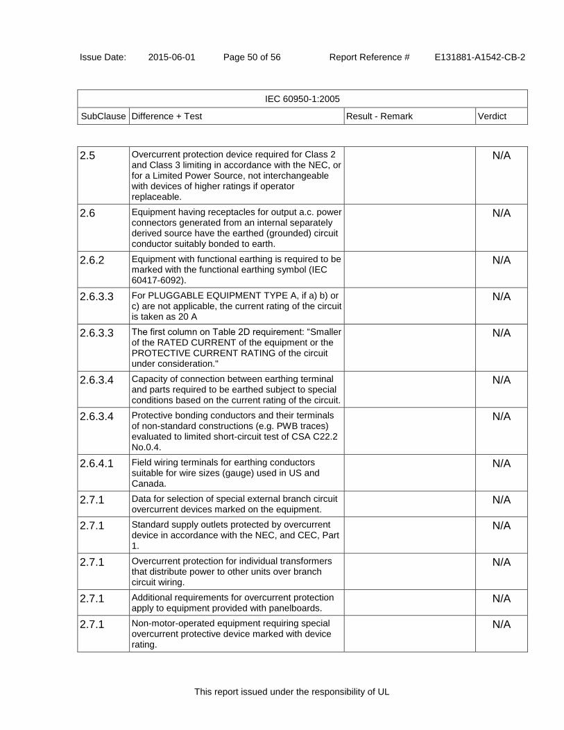
Issue Date: 2015-06-01 Page 50 of 56 Report Reference # E131881-A1542-CB-2
IEC 60950-1:2005
SubClause Difference + Test Result - Remark Verdict
This report issued under the responsibility of UL
2.5 Overcurrent protection device required for Class 2 and Class 3 limiting in accordance with the NEC, or for a Limited Power Source, not interchangeable with devices of higher ratings if operator replaceable.
N/A
2.6 Equipment having receptacles for output a.c. power connectors generated from an internal separately derived source have the earthed (grounded) circuit conductor suitably bonded to earth.
N/A
2.6.2 Equipment with functional earthing is required to be marked with the functional earthing symbol (IEC 60417-6092).
N/A
2.6.3.3 For PLUGGABLE EQUIPMENT TYPE A, if a) b) or c) are not applicable, the current rating of the circuit is taken as 20 A
N/A
2.6.3.3 The first column on Table 2D requirement: “Smaller of the RATED CURRENT of the equipment or the PROTECTIVE CURRENT RATING of the circuit under consideration."
N/A
2.6.3.4 Capacity of connection between earthing terminal and parts required to be earthed subject to special conditions based on the current rating of the circuit.
N/A
2.6.3.4 Protective bonding conductors and their terminals of non-standard constructions (e.g. PWB traces) evaluated to limited short-circuit test of CSA C22.2 No.0.4.
N/A
2.6.4.1 Field wiring terminals for earthing conductors suitable for wire sizes (gauge) used in US and Canada.
N/A
2.7.1 Data for selection of special external branch circuit overcurrent devices marked on the equipment.
N/A
2.7.1 Standard supply outlets protected by overcurrent device in accordance with the NEC, and CEC, Part 1.
N/A
2.7.1 Overcurrent protection for individual transformers that distribute power to other units over branch circuit wiring.
N/A
2.7.1 Additional requirements for overcurrent protection apply to equipment provided with panelboards.
N/A
2.7.1 Non-motor-operated equipment requiring special overcurrent protective device marked with device rating.
N/A

Issue Date: 2015-06-01 Page 51 of 56 Report Reference # E131881-A1542-CB-2
IEC 60950-1:2005
SubClause Difference + Test Result - Remark Verdict
This report issued under the responsibility of UL
2.10.5.12 Multi-layer winding wire subject to UL component wire requirements in addition to 2.10.5.12 and Annex U.
Pass
3.1.1 Permissible combinations of internal wiring/external cable sizes for overcurrent and short circuit protection.
All internal wires possess adequate cross-sectional areas for their intended application and all internal wirings are adequately insulated.
Pass
3.1.1 All interconnecting cables protected against overcurrent and short circuit.
All INTERCONNECTING CABLES possess adequate cross-sectional areas for their intended application and all internal wirings are adequately insulated.
Pass
3.2 Wiring methods permit connection of equipment to primary power supply in accordance with the NEC and CEC, Part 1.
Pass
3.2.1 Permitted use for flexible cords and plugs. Pass
3.2.1 Flexible cords provided with attachment plug rated 125% of equipment current rating.
See Table 1.5.1 Pass
3.2.1 Any Class II equipment provided with 15 or 20 A standard supply outlets, Edison-base lampholders or single pole disconnect device provided with a polarized type attachment plug.
N/A
3.2.1.2 Equipment intended for connection to DC mains supply power systems complies with special wiring requirements (e.g., no permanent connection to supply by flexible cord).
N/A
3.2.1.2 Equipment with one pole of the DC mains supply connected to both the equipment mains input terminal and the main protective earthing terminal provided with special instructions and construction provisions for earthing.
N/A
3.2.1.2 Equipment with means for connecting supply to earthing electrode conductor has no switches or protective devices between supply connection and earthing electrode connection.
N/A
3.2.1.2 Special markings and instructions for equipment with provisions to connect earthed conductor of a DC supply circuit to earthing conductor at the equipment.
N/A
3.2.1.2 Special markings and instructions for equipment N/A

Issue Date: 2015-06-01 Page 52 of 56 Report Reference # E131881-A1542-CB-2
IEC 60950-1:2005
SubClause Difference + Test Result - Remark Verdict
This report issued under the responsibility of UL
with earthed conductor of a DC supply circuit connected to the earthing conductor at the equipment.
3.2.1.2 Terminals and leads provided for permanent connection of DC powered equipment to supply marked to indicate polarity if reverse polarity may result in a hazard.
N/A
3.2.3 Permanently connected equipment has provision for connecting and securing a field wiring system (i.e. conduit, or leads etc.) per the NEC and CEC, Part 1.
N/A
3.2.3 Permanently connected equipment may have terminals or leads not smaller than No. 18 AWG (0.82 mm²) and not less than 150 mm in length for connection of field installed wiring.
N/A
3.2.3 If supply wires exceed 60 °C, marking indicates use of 75 °C or 90 °C wiring for supply connection as appropriate.
N/A
3.2.3 Equipment compatible with suitable trade sizes of conduits and cables.
N/A
3.2.5 Power supply cords are required to be no longer than 4.5 m in length. Minimum cord length is required to be 1.5 m, with certain constructions such as external power supplies allowed to consider both input and output cord lengths into the requirement. Flexible power supply cords are required to be compatible with Article 400 of the NEC, and Tables 11 and 12 of the CEC.
Pass
3.2.5 Conductors in power supply cords sized according to NEC and CEC, Part I.
Pass
3.2.5 Power supply cords and cord sets incorporate flexible cords suitable for the particular application.
Pass
3.2.6 Strain relief provided for non-detachable interconnecting cables not supplied by a limited power source.
N/A
3.2.9 Adequate wire bending space and volume of field wiring compartment required to properly make the field connections.
N/A
3.2.9 Equipment intended solely for installation in Restricted Access Locations using low voltage d.c.
N/A

Issue Date: 2015-06-01 Page 53 of 56 Report Reference # E131881-A1542-CB-2
IEC 60950-1:2005
SubClause Difference + Test Result - Remark Verdict
This report issued under the responsibility of UL
systems may not need provision for connecting and securing a field wiring system. A method of securing wiring or instructions provided to ensure the wiring is protected from abuse.
3.3 Field wiring terminals provided for interconnection of units for other than LPS or Class 2 circuits also comply with 3.3.
N/A
3.3 Interconnection of units by LPS or Class 2 conductors may have field wiring connectors other than those specified in 3.3 if wiring is reliably separated.
N/A
3.3.1 Terminals for the connection of neutral conductor identified by a distinctive white marking or other equally effective means.
N/A
3.3.3 Wire binding screw terminal permitted for connection of No. 10 AWG (5.3 mm²) or smaller conductor if provided with upturned lugs, cupped washer or equivalent retention.
N/A
3.3.4 Terminals accept wire sizes (gauge) used in the U.S. and Canada.
N/A
3.3.4 Terminals accept current-carrying conductors rated 125% of the equipment current rating.
N/A
3.3.5 First column of Table 3E revised to require “Smaller of the RATED CURRENT of the equipment or the PROTECTIVE CURRENT RATING of the circuit under consideration."
N/A
3.3.6 Field wiring terminals marked to indicate the material(s) of the conductor appropriate for the terminals used.
N/A
3.3.6 Connection of an aluminum conductor not permitted to terminal for equipment earthing conductor.
N/A
3.3.6 Field wiring connections made through the use of suitable pressure connectors (including set screw type), solder lugs or splices to flexible leads.
N/A
3.4.2 Separate motor control device(s) required for cord-connected equipment rated more than 12 A, or with motor rated more than 1/3 hp or more than 120 V.
N/A
3.4.8 Vertically mounted disconnect devices oriented so up position of handle is "on".
N/A
3.4.11 For computer-room applications, equipment with battery systems capable of supplying 750 VA for 5
N/A

Issue Date: 2015-06-01 Page 54 of 56 Report Reference # E131881-A1542-CB-2
IEC 60950-1:2005
SubClause Difference + Test Result - Remark Verdict
This report issued under the responsibility of UL
min require battery disconnect means.
4.2.8.1 Special opening restrictions for enclosures around CRTs with face dimension of 160 mm or more.
N/A
4.2.9 Compartment housing high-pressure lamp marked to indicate risk of explosion.
N/A
4.3.2 Loading test for equipment with handle(s) used to support more than 9 kg tested at four times the weight of the unit.
N/A
4.3.6 In addition to the IEC requirements, Direct Plug-in Equipment complies with UL 1310 or CSA 223 mechanical assembly requirements.
N/A
4.3.8 Battery packs for both portable and stationary applications are required to comply with special component requirements.
N/A
4.3.12 The maximum quantity of flammable liquid stored in equipment complies with ANSI/NFPA 30(Table NAE.6).
N/A
4.3.12 Equipment using replenishable liquids marked to indicate type of liquid to be used.
N/A
4.3.13.2 Equipment that produces x-radiation and does not comply with 4.3.12 under all conditions of servicing marked to indicate the presence of radiation where readily visible.
N/A
4.3.13.5.1
Requirements contained in the applicable national codes and regulations apply to lasers (21 CFR 1040 and REDR C1370).
N/A
4.7 Automated information storage equipment intended to contain more than 0.76 m³ of combustible media requires provision for automatic sprinklers or a gaseous agent extinguishing system.
N/A
4.7.3.1 Equipment for use in environmental air space other than ducts or plenums provided with metal enclosure or with non-metallic enclosure having adequate fire-resistance and low smoke producing characteristics. Low smoke-producing characteristics evaluated according to UL 2043. Equipment for installation in space used for environmental air as described in Sec. 300-22(c) of the NEC provided with instructions indicating suitability for installation in such locations.
N/A
4.7.3.1 Flame spread rating for external surface of combustible material with exposed area greater than 0.9 m² or a single dimension greater than 1.8
N/A

Issue Date: 2015-06-01 Page 55 of 56 Report Reference # E131881-A1542-CB-2
IEC 60950-1:2005
SubClause Difference + Test Result - Remark Verdict
This report issued under the responsibility of UL
m; 50 or less for computer room applications or 200 or less for other applications.
4.7.3.4 Wire marked "VW-1" or "FT-1" considered equivalent.
Pass
5.1.8.2 Special earthing provisions and instructions for equipment with high touch current due to telecommunication network connections.
N/A
5.1.8.3 Touch current due to ringing voltage for equipment containing telecommunication network leads.
N/A
5.3.7 Overloading of SELV connectors and printed wiring board receptacles accessible to the operator.
N/A
5.3.7 Tests interrupted by opening of a component repeated two additional times.
N/A
5.3.9.1 Test interrupted by opening of wire or trace subject to certain conditions.
N/A
6 Specialized instructions provided for telephones that may be connected to a telecommunications network.
No TNV presents. N/A
6 Marking identifying function of telecommunication type connectors not used for connection to a telecommunication network.
N/A
6.3 Equipment remotely powered over telecommunication wiring systems provided with specialized markings adjacent to the connection.
N/A
6.3 Overcurrent protection incorporated into equipment to provide power over telecommunication wiring system not interchangeable with devices of higher ratings if operator replaceable.
N/A
6.4 Additional requirements for equipment intended for connection to a telecommunication network using cable subject to overvoltage from power line failures (Fig. 6C).
N/A
6.4 Where 26 AWG line cord required by Fig. 6C, either the cord is provided with the equipment or described in the safety instructions.
N/A
7 Equipment associated with the cable distribution system may need to be subjected to applicable parts of Chapter 8 of the NEC.
N/A
H Ionizing radiation measurements made under single fault conditions in accordance with the requirements of the Code of Federal Regulations 21 CFR 1020 and the Canadian Radiation Emitting
N/A

Issue Date: 2015-06-01 Page 56 of 56 Report Reference # E131881-A1542-CB-2
IEC 60950-1:2005
SubClause Difference + Test Result - Remark Verdict
This report issued under the responsibility of UL
Devices Act, REDR C1370.
M.2 Continuous ringing signals evaluated to Method A subjected to special accessibility considerations.
N/A
M.4 Special requirements for message waiting and similar telecommunications signals.
N/A
NAC Equipment intended for use with a generic secondary protector marked with suitable instructions.
N/A
NAC Equipment intended for use with a specific primary or secondary protector marked with suitable instructions.
N/A
NAD Acoustic pressure from an ear piece less than 140 dBA for short duration disturbances, and less than 125 dBA for handsets, 118 dBA for headsets and insert earphones, for long duration disturbances.
N/A
NAD Equipment connected to a telecommunication and cable distribution networks and supplied with an earphone intended to be held against, or in the ear is required to comply with special acoustic pressure requirements.
N/A
EE.5 UL articulated accessibility probe (Fig. EE.3) required for assessing accessibility to document/media shredders, instead of Figure 2A test finger.
N/A

Issue Date: 2015-06-01 Page 57 of 56 Report Reference # E131881-A1542-CB-2
IEC 60950-1:2005
SubClause Difference + Test Result - Remark Verdict
This report issued under the responsibility of UL
United Kingdom - Differences to IEC 60950-1:2005 (Second Edition); Am1:2009 + Am2:2013
2.6.3.3 The current rating of the circuit shall be taken as 13 A, not 16 A.
N/A
2.7.1 To protect against excessive currents and short-circuits in the PRIMARY CIRCUIT of DIRECT PLUG-IN EQUIPMENT, tests according to 5.3 shall be conducted, using an external protective device rated 30 A or 32 A. If these tests fail, suitable protective devices shall be included as integral parts of the DIRECT PLUG-IN EQUIPMENT, so that the requirements of 5.3 are met.
N/A
3.2.1.1 Apparatus which is fitted with a flexible cable or cord and is designed to be connected to a mains socket conforming to BS 1363 by means of that flexible cable or cord and plug, shall be fitted with a "standard plug" in accordance with Statutory Instrument 1786: 1994 - The Plugs and Sockets etc. (Safety) Regulations 1994, unless exempted by those regulations. NOTE: "Standard plug" is defined in SI 1786: 1994 and essentially means an approved plug conforming to BS 1363 or an approved conversion plug.
N/A
3.2.5.1 A power supply cord with conductor of 1.25 mm² is allowed for equipment with a rated current over 10A and up to and including 13A.
N/A
3.3.4 The range of conductor sizes of flexible cords to be accepted by terminals for equipment with a rated current of over 10 A up to and including 13 A is 1.25 mm² to 1.5 mm² nominal cross-sectional area.
N/A
4.3.6 The torque test is performed using a socket outlet complying with BS 1363 and the plug part of DIRECT PLUG-IN EQUIPMENT shall be assessed to BS 1363: Part 1, 12.1, 12.2, 12.3, 12.9, 12.11, 12.12, 12.16 and 12.17, except that the test of 12.17 is performed at not less than 125°C.
N/A
4.3.6 Where the metal earth pin is replaced by an Insulated Shutter Opening Device (ISOD), the requirements of clauses 22.2 and 23 also apply.
N/A

Issue Date: 2015-06-01 Page 1 of 115 Report Reference # E131881-A1542-CB-2
Enclosures
This report issued under the responsibility of UL
Enclosures
Type Supplement Id Description
Photographs 3-01 External View - Inlet side
Photographs 3-02 External View - Cover side
Photographs 3-03 External View - Chassis side
Photographs 3-04 Side View 1
Photographs 3-05 Side View 2
Photographs 3-06 Construction A - Internal View 1- with metal shielding
Photographs 3-07 Construction A - Internal View 2- with metal shielding
Photographs 3-08 Construction A - internal 3 -without metal shielding
Photographs 3-09 Construction A - internal 4 -without metal shielding
Photographs 3-10 Construction A - Component Side View
Photographs 3-11 Construction A - Trace Side View
Photographs 3-12 Construction A - Glue Point View 1
Photographs 3-13 Construction A - Glue Point View 2
Photographs 3-15 Construction A - Trace side view(add one tape on outside of transformer)
Photographs 3-16 Component side(transformer with tape)
Photographs 3-17 Construction A - Transformer view-1(with tape)
Photographs 3-18 Construction A - Transformer view-2(with tape)
Photographs 3-19 Construction A - Trace side view( one tape was added on transformer MV-MP12664)
Photographs 3-20 Construction B Internal View 1- with metal shielding
Photographs 3-21 Construction B Internal View 2- with metal shielding
Photographs 3-22 Construction B Internal View 3- open metal shielding
Photographs 3-23 Construction B Component side
Photographs 3-24 Construction B - Trace side
Diagrams 4-01 Construction A - Line Filter FL1 Spec
Diagrams 4-02 Construction A - Line Filter FL2 Spec
Diagrams 4-03 Line Filter L1 Spec
Diagrams 4-04 Construction A - Line Filter L2 Spec
Diagrams 4-05 Construction A - Transformer T1 Spec
Diagrams 4-06 Enclosure chassis
Diagrams 4-07 Enclosure cover
Diagrams 4-08 Output Cord and strain relief
Diagrams 4-09 Construction A - Shield Top (EMI Shielding)

Issue Date: 2015-06-01 Page 2 of 115 Report Reference # E131881-A1542-CB-2
Enclosures
This report issued under the responsibility of UL
Diagrams 4-10 Construction A - Shield Ass'y (EMI Shielding)
Diagrams 4-12 Construction A - Heatsink Spec
Diagrams 4-13 Construction A - Glue Location and Amount
Diagrams 4-14 Construction A - Working voltage location(A1 to A4)
Diagrams 4-15 Construction A - Alternative transformer T1 spec.
Diagrams 4-16 Construction B - Line Filter FL1 Spec
Diagrams 4-17 Construction B - Line Filter FL2 Spec
Diagrams 4-18 Construction B - Line Filter L2 Spec
Diagrams 4-19 Construction B - Alternative transformer T1 spec. (MV-MP15038)
Diagrams 4-20 Construction B - Shield Ass'y
Diagrams 4-21 Construction B - Shield Top
Diagrams 4-22 Construction B Heatsink (HS1, HS2, HS3)
Diagrams 4-23 Construction B - Glue location
Schematics + PWB 5-01 Construction A - Model ADP-120RH B PWB Layout (P/N: ADP-120RH BA)
Schematics + PWB 5-02 Construction B - Model ADP-120RH B PWB Layout (P/N: ADP-120RH DA)
Miscellaneous 7-01 Multiple Factories Declaration
Miscellaneous 7-02 TMP test equipment list
Miscellaneous 7-03 Model difference
Marking Plate 13-01 Marking Plate for Model ADP-120RH B

Issue Date: 2015-06-01 Page 3 of 115 Report Reference # E131881-A1542-CB-2
Enclosures
This report issued under the responsibility of UL
MarkingPlate ID 13-01

Issue Date: 2015-06-01 Page 4 of 115 Report Reference # E131881-A1542-CB-2
Enclosures
This report issued under the responsibility of UL
Photographs ID 3-01

Issue Date: 2015-06-01 Page 5 of 115 Report Reference # E131881-A1542-CB-2
Enclosures
This report issued under the responsibility of UL
Photographs ID 3-02

Issue Date: 2015-06-01 Page 6 of 115 Report Reference # E131881-A1542-CB-2
Enclosures
This report issued under the responsibility of UL
Photographs ID 3-03

Issue Date: 2015-06-01 Page 7 of 115 Report Reference # E131881-A1542-CB-2
Enclosures
This report issued under the responsibility of UL
Photographs ID 3-04

Issue Date: 2015-06-01 Page 8 of 115 Report Reference # E131881-A1542-CB-2
Enclosures
This report issued under the responsibility of UL
Photographs ID 3-05

Issue Date: 2015-06-01 Page 9 of 115 Report Reference # E131881-A1542-CB-2
Enclosures
This report issued under the responsibility of UL
Photographs ID 3-06

Issue Date: 2015-06-01 Page 10 of 115 Report Reference # E131881-A1542-CB-2
Enclosures
This report issued under the responsibility of UL
Photographs ID 3-07

Issue Date: 2015-06-01 Page 11 of 115 Report Reference # E131881-A1542-CB-2
Enclosures
This report issued under the responsibility of UL
Photographs ID 3-08

Issue Date: 2015-06-01 Page 12 of 115 Report Reference # E131881-A1542-CB-2
Enclosures
This report issued under the responsibility of UL
Photographs ID 3-09

Issue Date: 2015-06-01 Page 13 of 115 Report Reference # E131881-A1542-CB-2
Enclosures
This report issued under the responsibility of UL
Photographs ID 3-10

Issue Date: 2015-06-01 Page 14 of 115 Report Reference # E131881-A1542-CB-2
Enclosures
This report issued under the responsibility of UL
Photographs ID 3-11

Issue Date: 2015-06-01 Page 15 of 115 Report Reference # E131881-A1542-CB-2
Enclosures
This report issued under the responsibility of UL
Photographs ID 3-12

Issue Date: 2015-06-01 Page 16 of 115 Report Reference # E131881-A1542-CB-2
Enclosures
This report issued under the responsibility of UL
Photographs ID 3-13

Issue Date: 2015-06-01 Page 17 of 115 Report Reference # E131881-A1542-CB-2
Enclosures
This report issued under the responsibility of UL
Photographs ID 3-15

Issue Date: 2015-06-01 Page 18 of 115 Report Reference # E131881-A1542-CB-2
Enclosures
This report issued under the responsibility of UL
Photographs ID 3-16

Issue Date: 2015-06-01 Page 19 of 115 Report Reference # E131881-A1542-CB-2
Enclosures
This report issued under the responsibility of UL
Photographs ID 3-17

Issue Date: 2015-06-01 Page 20 of 115 Report Reference # E131881-A1542-CB-2
Enclosures
This report issued under the responsibility of UL
Photographs ID 3-18

Issue Date: 2015-06-01 Page 21 of 115 Report Reference # E131881-A1542-CB-2
Enclosures
This report issued under the responsibility of UL
Photographs ID 3-19

Issue Date: 2015-06-01 Page 22 of 115 Report Reference # E131881-A1542-CB-2
Enclosures
This report issued under the responsibility of UL
Photographs ID 3-20

Issue Date: 2015-06-01 Page 23 of 115 Report Reference # E131881-A1542-CB-2
Enclosures
This report issued under the responsibility of UL
Photographs ID 3-21

Issue Date: 2015-06-01 Page 24 of 115 Report Reference # E131881-A1542-CB-2
Enclosures
This report issued under the responsibility of UL
Photographs ID 3-22

Issue Date: 2015-06-01 Page 25 of 115 Report Reference # E131881-A1542-CB-2
Enclosures
This report issued under the responsibility of UL
Photographs ID 3-23

Issue Date: 2015-06-01 Page 26 of 115 Report Reference # E131881-A1542-CB-2
Enclosures
This report issued under the responsibility of UL
Photographs ID 3-24

Issue Date: 2015-06-01 Page 27 of 115 Report Reference # E131881-A1542-CB-2
Enclosures
This report issued under the responsibility of UL
Diagrams ID 4-01

Issue Date: 2015-06-01 Page 28 of 115 Report Reference # E131881-A1542-CB-2
Enclosures
This report issued under the responsibility of UL
Diagrams ID 4-01

Issue Date: 2015-06-01 Page 29 of 115 Report Reference # E131881-A1542-CB-2
Enclosures
This report issued under the responsibility of UL
Diagrams ID 4-01

Issue Date: 2015-06-01 Page 30 of 115 Report Reference # E131881-A1542-CB-2
Enclosures
This report issued under the responsibility of UL
Diagrams ID 4-01

Issue Date: 2015-06-01 Page 31 of 115 Report Reference # E131881-A1542-CB-2
Enclosures
This report issued under the responsibility of UL
Diagrams ID 4-02

Issue Date: 2015-06-01 Page 32 of 115 Report Reference # E131881-A1542-CB-2
Enclosures
This report issued under the responsibility of UL
Diagrams ID 4-02

Issue Date: 2015-06-01 Page 33 of 115 Report Reference # E131881-A1542-CB-2
Enclosures
This report issued under the responsibility of UL
Diagrams ID 4-02
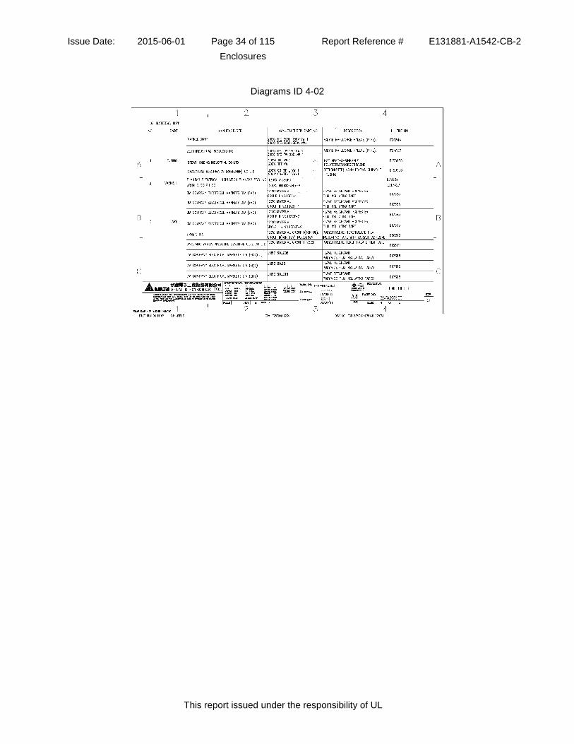
Issue Date: 2015-06-01 Page 34 of 115 Report Reference # E131881-A1542-CB-2
Enclosures
This report issued under the responsibility of UL
Diagrams ID 4-02

Issue Date: 2015-06-01 Page 35 of 115 Report Reference # E131881-A1542-CB-2
Enclosures
This report issued under the responsibility of UL
Diagrams ID 4-02

Issue Date: 2015-06-01 Page 36 of 115 Report Reference # E131881-A1542-CB-2
Enclosures
This report issued under the responsibility of UL
Diagrams ID 4-02

Issue Date: 2015-06-01 Page 37 of 115 Report Reference # E131881-A1542-CB-2
Enclosures
This report issued under the responsibility of UL
Diagrams ID 4-03

Issue Date: 2015-06-01 Page 38 of 115 Report Reference # E131881-A1542-CB-2
Enclosures
This report issued under the responsibility of UL
Diagrams ID 4-03

Issue Date: 2015-06-01 Page 39 of 115 Report Reference # E131881-A1542-CB-2
Enclosures
This report issued under the responsibility of UL
Diagrams ID 4-03

Issue Date: 2015-06-01 Page 40 of 115 Report Reference # E131881-A1542-CB-2
Enclosures
This report issued under the responsibility of UL
Diagrams ID 4-03

Issue Date: 2015-06-01 Page 41 of 115 Report Reference # E131881-A1542-CB-2
Enclosures
This report issued under the responsibility of UL
Diagrams ID 4-04

Issue Date: 2015-06-01 Page 42 of 115 Report Reference # E131881-A1542-CB-2
Enclosures
This report issued under the responsibility of UL
Diagrams ID 4-04

Issue Date: 2015-06-01 Page 43 of 115 Report Reference # E131881-A1542-CB-2
Enclosures
This report issued under the responsibility of UL
Diagrams ID 4-04

Issue Date: 2015-06-01 Page 44 of 115 Report Reference # E131881-A1542-CB-2
Enclosures
This report issued under the responsibility of UL
Diagrams ID 4-04

Issue Date: 2015-06-01 Page 45 of 115 Report Reference # E131881-A1542-CB-2
Enclosures
This report issued under the responsibility of UL
Diagrams ID 4-04

Issue Date: 2015-06-01 Page 46 of 115 Report Reference # E131881-A1542-CB-2
Enclosures
This report issued under the responsibility of UL
Diagrams ID 4-04

Issue Date: 2015-06-01 Page 47 of 115 Report Reference # E131881-A1542-CB-2
Enclosures
This report issued under the responsibility of UL
Diagrams ID 4-04

Issue Date: 2015-06-01 Page 48 of 115 Report Reference # E131881-A1542-CB-2
Enclosures
This report issued under the responsibility of UL
Diagrams ID 4-05

Issue Date: 2015-06-01 Page 49 of 115 Report Reference # E131881-A1542-CB-2
Enclosures
This report issued under the responsibility of UL
Diagrams ID 4-05

Issue Date: 2015-06-01 Page 50 of 115 Report Reference # E131881-A1542-CB-2
Enclosures
This report issued under the responsibility of UL
Diagrams ID 4-05

Issue Date: 2015-06-01 Page 51 of 115 Report Reference # E131881-A1542-CB-2
Enclosures
This report issued under the responsibility of UL
Diagrams ID 4-05

Issue Date: 2015-06-01 Page 52 of 115 Report Reference # E131881-A1542-CB-2
Enclosures
This report issued under the responsibility of UL
Diagrams ID 4-05

Issue Date: 2015-06-01 Page 53 of 115 Report Reference # E131881-A1542-CB-2
Enclosures
This report issued under the responsibility of UL
Diagrams ID 4-05

Issue Date: 2015-06-01 Page 54 of 115 Report Reference # E131881-A1542-CB-2
Enclosures
This report issued under the responsibility of UL
Diagrams ID 4-05

Issue Date: 2015-06-01 Page 55 of 115 Report Reference # E131881-A1542-CB-2
Enclosures
This report issued under the responsibility of UL
Diagrams ID 4-05

Issue Date: 2015-06-01 Page 56 of 115 Report Reference # E131881-A1542-CB-2
Enclosures
This report issued under the responsibility of UL
Diagrams ID 4-05

Issue Date: 2015-06-01 Page 57 of 115 Report Reference # E131881-A1542-CB-2
Enclosures
This report issued under the responsibility of UL
Diagrams ID 4-05

Issue Date: 2015-06-01 Page 58 of 115 Report Reference # E131881-A1542-CB-2
Enclosures
This report issued under the responsibility of UL
Diagrams ID 4-05

Issue Date: 2015-06-01 Page 59 of 115 Report Reference # E131881-A1542-CB-2
Enclosures
This report issued under the responsibility of UL
Diagrams ID 4-05

Issue Date: 2015-06-01 Page 60 of 115 Report Reference # E131881-A1542-CB-2
Enclosures
This report issued under the responsibility of UL
Diagrams ID 4-06

Issue Date: 2015-06-01 Page 61 of 115 Report Reference # E131881-A1542-CB-2
Enclosures
This report issued under the responsibility of UL
Diagrams ID 4-06

Issue Date: 2015-06-01 Page 62 of 115 Report Reference # E131881-A1542-CB-2
Enclosures
This report issued under the responsibility of UL
Diagrams ID 4-07

Issue Date: 2015-06-01 Page 63 of 115 Report Reference # E131881-A1542-CB-2
Enclosures
This report issued under the responsibility of UL
Diagrams ID 4-07

Issue Date: 2015-06-01 Page 64 of 115 Report Reference # E131881-A1542-CB-2
Enclosures
This report issued under the responsibility of UL
Diagrams ID 4-08

Issue Date: 2015-06-01 Page 65 of 115 Report Reference # E131881-A1542-CB-2
Enclosures
This report issued under the responsibility of UL
Diagrams ID 4-08

Issue Date: 2015-06-01 Page 66 of 115 Report Reference # E131881-A1542-CB-2
Enclosures
This report issued under the responsibility of UL
Diagrams ID 4-09

Issue Date: 2015-06-01 Page 67 of 115 Report Reference # E131881-A1542-CB-2
Enclosures
This report issued under the responsibility of UL
Diagrams ID 4-09
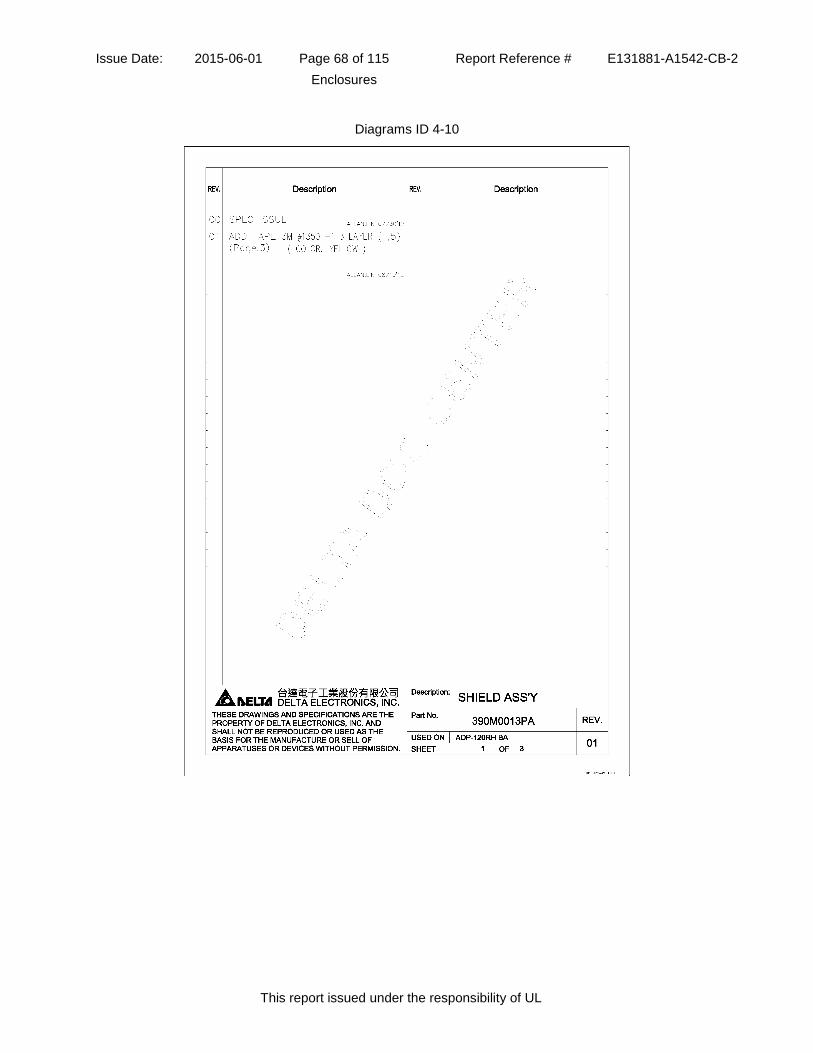
Issue Date: 2015-06-01 Page 68 of 115 Report Reference # E131881-A1542-CB-2
Enclosures
This report issued under the responsibility of UL
Diagrams ID 4-10

Issue Date: 2015-06-01 Page 69 of 115 Report Reference # E131881-A1542-CB-2
Enclosures
This report issued under the responsibility of UL
Diagrams ID 4-10

Issue Date: 2015-06-01 Page 70 of 115 Report Reference # E131881-A1542-CB-2
Enclosures
This report issued under the responsibility of UL
Diagrams ID 4-10

Issue Date: 2015-06-01 Page 71 of 115 Report Reference # E131881-A1542-CB-2
Enclosures
This report issued under the responsibility of UL
Diagrams ID 4-12

Issue Date: 2015-06-01 Page 72 of 115 Report Reference # E131881-A1542-CB-2
Enclosures
This report issued under the responsibility of UL
Diagrams ID 4-12

Issue Date: 2015-06-01 Page 73 of 115 Report Reference # E131881-A1542-CB-2
Enclosures
This report issued under the responsibility of UL
Diagrams ID 4-12

Issue Date: 2015-06-01 Page 74 of 115 Report Reference # E131881-A1542-CB-2
Enclosures
This report issued under the responsibility of UL
Diagrams ID 4-13

Issue Date: 2015-06-01 Page 75 of 115 Report Reference # E131881-A1542-CB-2
Enclosures
This report issued under the responsibility of UL
Diagrams ID 4-13

Issue Date: 2015-06-01 Page 76 of 115 Report Reference # E131881-A1542-CB-2
Enclosures
This report issued under the responsibility of UL
Diagrams ID 4-14

Issue Date: 2015-06-01 Page 77 of 115 Report Reference # E131881-A1542-CB-2
Enclosures
This report issued under the responsibility of UL
Diagrams ID 4-15

Issue Date: 2015-06-01 Page 78 of 115 Report Reference # E131881-A1542-CB-2
Enclosures
This report issued under the responsibility of UL
Diagrams ID 4-15

Issue Date: 2015-06-01 Page 79 of 115 Report Reference # E131881-A1542-CB-2
Enclosures
This report issued under the responsibility of UL
Diagrams ID 4-15

Issue Date: 2015-06-01 Page 80 of 115 Report Reference # E131881-A1542-CB-2
Enclosures
This report issued under the responsibility of UL
Diagrams ID 4-15

Issue Date: 2015-06-01 Page 81 of 115 Report Reference # E131881-A1542-CB-2
Enclosures
This report issued under the responsibility of UL
Diagrams ID 4-15

Issue Date: 2015-06-01 Page 82 of 115 Report Reference # E131881-A1542-CB-2
Enclosures
This report issued under the responsibility of UL
Diagrams ID 4-15

Issue Date: 2015-06-01 Page 83 of 115 Report Reference # E131881-A1542-CB-2
Enclosures
This report issued under the responsibility of UL
Diagrams ID 4-15

Issue Date: 2015-06-01 Page 84 of 115 Report Reference # E131881-A1542-CB-2
Enclosures
This report issued under the responsibility of UL
Diagrams ID 4-16

Issue Date: 2015-06-01 Page 85 of 115 Report Reference # E131881-A1542-CB-2
Enclosures
This report issued under the responsibility of UL
Diagrams ID 4-16

Issue Date: 2015-06-01 Page 86 of 115 Report Reference # E131881-A1542-CB-2
Enclosures
This report issued under the responsibility of UL
Diagrams ID 4-17

Issue Date: 2015-06-01 Page 87 of 115 Report Reference # E131881-A1542-CB-2
Enclosures
This report issued under the responsibility of UL
Diagrams ID 4-17

Issue Date: 2015-06-01 Page 88 of 115 Report Reference # E131881-A1542-CB-2
Enclosures
This report issued under the responsibility of UL
Diagrams ID 4-17

Issue Date: 2015-06-01 Page 89 of 115 Report Reference # E131881-A1542-CB-2
Enclosures
This report issued under the responsibility of UL
Diagrams ID 4-17

Issue Date: 2015-06-01 Page 90 of 115 Report Reference # E131881-A1542-CB-2
Enclosures
This report issued under the responsibility of UL
Diagrams ID 4-18

Issue Date: 2015-06-01 Page 91 of 115 Report Reference # E131881-A1542-CB-2
Enclosures
This report issued under the responsibility of UL
Diagrams ID 4-18

Issue Date: 2015-06-01 Page 92 of 115 Report Reference # E131881-A1542-CB-2
Enclosures
This report issued under the responsibility of UL
Diagrams ID 4-18

Issue Date: 2015-06-01 Page 93 of 115 Report Reference # E131881-A1542-CB-2
Enclosures
This report issued under the responsibility of UL
Diagrams ID 4-19

Issue Date: 2015-06-01 Page 94 of 115 Report Reference # E131881-A1542-CB-2
Enclosures
This report issued under the responsibility of UL
Diagrams ID 4-19

Issue Date: 2015-06-01 Page 95 of 115 Report Reference # E131881-A1542-CB-2
Enclosures
This report issued under the responsibility of UL
Diagrams ID 4-19

Issue Date: 2015-06-01 Page 96 of 115 Report Reference # E131881-A1542-CB-2
Enclosures
This report issued under the responsibility of UL
Diagrams ID 4-19

Issue Date: 2015-06-01 Page 97 of 115 Report Reference # E131881-A1542-CB-2
Enclosures
This report issued under the responsibility of UL
Diagrams ID 4-20

Issue Date: 2015-06-01 Page 98 of 115 Report Reference # E131881-A1542-CB-2
Enclosures
This report issued under the responsibility of UL
Diagrams ID 4-20

Issue Date: 2015-06-01 Page 99 of 115 Report Reference # E131881-A1542-CB-2
Enclosures
This report issued under the responsibility of UL
Diagrams ID 4-21

Issue Date: 2015-06-01 Page 100 of 115 Report Reference # E131881-A1542-CB-2
Enclosures
This report issued under the responsibility of UL
Diagrams ID 4-22

Issue Date: 2015-06-01 Page 101 of 115 Report Reference # E131881-A1542-CB-2
Enclosures
This report issued under the responsibility of UL
Diagrams ID 4-22

Issue Date: 2015-06-01 Page 102 of 115 Report Reference # E131881-A1542-CB-2
Enclosures
This report issued under the responsibility of UL
Diagrams ID 4-22

Issue Date: 2015-06-01 Page 103 of 115 Report Reference # E131881-A1542-CB-2
Enclosures
This report issued under the responsibility of UL
Diagrams ID 4-23
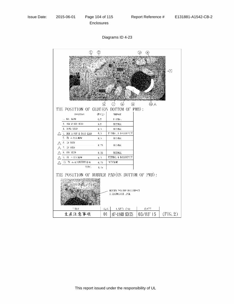
Issue Date: 2015-06-01 Page 104 of 115 Report Reference # E131881-A1542-CB-2
Enclosures
This report issued under the responsibility of UL
Diagrams ID 4-23

Issue Date: 2015-06-01 Page 105 of 115 Report Reference # E131881-A1542-CB-2
Enclosures
This report issued under the responsibility of UL
Schematics ID 5-01

Issue Date: 2015-06-01 Page 106 of 115 Report Reference # E131881-A1542-CB-2
Enclosures
This report issued under the responsibility of UL
Schematics ID 5-01

Issue Date: 2015-06-01 Page 107 of 115 Report Reference # E131881-A1542-CB-2
Enclosures
This report issued under the responsibility of UL
Schematics ID 5-01

Issue Date: 2015-06-01 Page 108 of 115 Report Reference # E131881-A1542-CB-2
Enclosures
This report issued under the responsibility of UL
Schematics ID 5-01

Issue Date: 2015-06-01 Page 109 of 115 Report Reference # E131881-A1542-CB-2
Enclosures
This report issued under the responsibility of UL
Schematics ID 5-01

Issue Date: 2015-06-01 Page 110 of 115 Report Reference # E131881-A1542-CB-2
Enclosures
This report issued under the responsibility of UL
Schematics ID 5-02

Issue Date: 2015-06-01 Page 111 of 115 Report Reference # E131881-A1542-CB-2
Enclosures
This report issued under the responsibility of UL
Schematics ID 5-02

Issue Date: 2015-06-01 Page 112 of 115 Report Reference # E131881-A1542-CB-2
Enclosures
This report issued under the responsibility of UL
Misc ID 7-01

Issue Date: 2015-06-01 Page 113 of 115 Report Reference # E131881-A1542-CB-2
Enclosures
This report issued under the responsibility of UL
Misc ID 7-01

Issue Date: 2015-06-01 Page 114 of 115 Report Reference # E131881-A1542-CB-2
Enclosures
This report issued under the responsibility of UL
Misc ID 7-02

Issue Date: 2015-06-01 Page 115 of 115 Report Reference # E131881-A1542-CB-2
Enclosures
This report issued under the responsibility of UL
Misc ID 7-03


![5DWD ,23 67& +$//, (Ul , 3HUMDQWDL NOR ,, RVD NOR · 5DWD ,23 67& +$//, (Ul , 3HUMDQWDL NOR ,, RVD NOR ,23 < ,23 >dK ^ }, ÇD ^< ,23D Z: E EZ ] } :](https://img.dokumen.tips/doc/110x75/5ea6ff9b41ed8413b66b72aa/5dwd-23-67-ul-3humdqwdl-nor-rvd-nor-5dwd-23-67-ul.jpg)