Embed Size (px)
Citation preview

DIVISION 33 – UTILITIES 33 00 00 UTILITIES 33 00 50 Design Criteria 33 01 00 General Requirements 33 05 00 Common Work Results 33 05 13 Manholes 33 05 16 Tunnels 33 08 00 Commissioning 33 10 00 WATER UTILITIES 33 11 00 Water Distribution Piping 33 11 19 Fire Suppression Water Distribution Piping 33 12 00 Water Distribution Equipment 33 12 19 Fire Hydrants 33 30 00 SANITARY SEWERAGE UTILITIES 33 31 00 Sanitary Sewerage Piping 33 40 00 STORM DRAINAGE UTILITIES 33 41 00 Storm Drainage Piping 33 44 19 Storm Water Treatment 33 50 00 FUEL DISTRIBUTION UTILITIES 33 51 00 Natural Gas Distribution 33 60 00 HYDRONIC AND STEAM ENERGY UTILITIES 33 61 00 Hydronic Distribution 33 63 00 Steam and Condensate Distribution 33 70 00 ELECTRICAL UTILITIES (See Electrical AE Manual) 33 80 00 COMMUNICATIONS UTILITIES (See Electrical AE Manual)

7 July 2014 USU A/E Design Manual 1
DIVISION 33 – UTILITIES 33 00 00 UTILITIES 33 00 50 Design Criteria
A. Refer to the DFCM website for the latest mechanical design requirements. USU design requirements include the DFCM design requirements.
B. Comply with the latest (Utah adopted) edition of the International
Codes: International Building Code (IBC), International Mechanical Code (IMC) International Plumbing Code (IPC) International Fuel Gas Code (IFGC) International Energy Conservation Code (IECC) International Fire Code (IFC) National Electric Code (NEC) All state amendments.
C. Comply with all applicable local, state, and federal codes and
regulations. D. Submit site utility basis of design with schematic design, design
development, 100% review documents for all new buildings and major remodels. Submit design calculations for all site utility systems.
33 01 00 General Requirements
A. Test and inspect all utility installations with a representative of the university present prior to backfill of utility piping.
B. Schedule all utility shutdowns 7 days in advance. Submit written
request to USU project manager.
C. Obtain a digging permit from USU FD&C prior to starting work. Allow 3 days for processing.
D. Comply with UPDES Storm Water General Permit for construction
activities. 33 05 00 Common Work Results
A. Refer to Division 32 for irrigation piping.

7 July 2014 USU A/E Design Manual 2
B. Manufacturing: Provide USA made utility piping, fittings, and appurtenances.
C. Piping Installation: Install all piping according to manufacturer’s
instructions. Use primer and glue on plastic pipe and conduit as recommended by piping manufacturer.
D. Existing Utilities: Locate and protect all existing utilities, structures,
landscaping, and other existing features prior to excavation. “Pot hole” existing utilities as required to locate critical utility lines.
E. Temporary Service: Provide temporary utility service prior to
excavation where critical utilities are affected. Coordinate requirements with USU.
F. Damaged Utilities: Repair and/or replace utility lines damaged during
excavation. Repairs and replacements require inspection by designated USU representative.
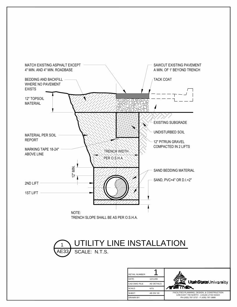
G. Utility Bedding: Provide appropriate compacted pipe bedding
consisting of sand or other appropriate material. H. Backfill Material: Provide backfill free of boulders larger than 4”.
Compact and test all backfill according to ASTM compaction standards.
I. Backfill Density: Provide 96% compaction conforming to ASTM
compaction standards for all backfill installed under paved areas, sidewalks, or excavations greater than five feet deep.
J. Topsoil: Provide 12” of topsoil in landscape areas. K. Refer to Detail No. 1/AE33 for pipe bedding and backfill requirements. L. Marking Tape: Install appropriately labeled detectable warning tape 18”
to 24” above top of utility line. If conditions cause tape to be less than 12 inches below surface grade then consult with USU representative to determine location.
33 05 13 Manholes and Structures
A. Place mastic sealer between each precast section.
B. Vacuum test underground structures according to ASTM C1244.
C. Install flat (to grade) lid structures in landscape areas a minimum of 12 inches below finished surface grade to allow for topsoil.

7 July 2014 USU A/E Design Manual 3
D. Install a maximum of 12 inches of grade rings (total rise of 18 inches including manhole ring) on underground structures. Use a mastic sealer between manhole rings.
E. Set manhole access cover to surrounding grade. F. Install underground structure access covers with proper utility
identification cast into the cover. G. Provide ladder access into all manholes and structures.
33 5 16 Tunnels
A. The purpose of the campus tunnel system is to provide an accessible
corridor for the following utilities:
1. Steam 2. Condensate 3. Chilled Water 4. Communications 5. Electrical
B. General Tunnel Requirements:
1. Design all new tunnels to meet all of the requirements in this section.
2. Construct all new tunnels of cast-in-place concrete. 3. Provide tunnel walkway minimum clearance of 4 ft. wide x 8 ft.
height between piping support systems. See Detail No. 2/AE33. 4. Design tunnel offsets to not exceed 30 degrees. 5. Provide expansion joints at all building connections and in the
tunnel sections as required by the structural engineer. See Detail No. 3/AE33.
6. Slope tunnels to drain into tunnel nodes.
C. Main Tunnels:
1. Size: 10’ wide x 10’ height (inside dimensions) 2. Floor: Maintain continuous grade with no drops or rises. 3. See Detail No. 4/AE33 for typical section of main tunnel.
D. Branch Tunnels:
1. Size: 8’ wide x 9’ height (inside dimensions) 2. Floor: Provide stairs, steps, or ladders for any change in elevation
at building connections. 3. See Detail No. 5/AE33 for typical section of branch tunnel. 4. Provide water proof seal and an expansion joint at tunnel
connections to buildings. See Detail No. 6/AE33.
7 July 2014 USU A/E Design Manual 4
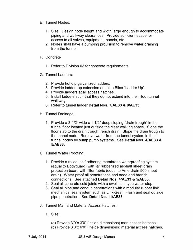
E. Tunnel Nodes:
1. Size: Design node height and width large enough to accommodate piping and walkway clearances. Provide sufficient space for access to all valves, equipment, panels, etc.
2. Nodes shall have a pumping provision to remove water draining from the tunnel.
F. Concrete
1. Refer to Division 03 for concrete requirements.
G. Tunnel Ladders:
2. Provide hot dip galvanized ladders. 3. Provide ladder top extension equal to Bilco “Ladder Up”. 4. Provide ladders at all access hatches. 5. Install ladders such that they do not extend into the 4-foot tunnel
walkway. 6. Refer to tunnel ladder Detail Nos. 7/AE33 & 8/AE33.
H. Tunnel Drainage:
1. Provide a 3-1/2” wide x 1-1/2” deep sloping “drain trough” in the
tunnel floor located just outside the clear walking space. Slope the floor slab to the drain trough trench drain. Slope the drain trough to the tunnel node. Remove water from the tunnel system in the tunnel nodes by sump pump systems. See Detail Nos. 4/AE33 & 5/AE33.
I. Tunnel Water Proofing:
1. Provide a rolled, self-adhering membrane waterproofing system
(equal to Bodyguard) with ½” rubberized asphalt sheet drain protection board with filter fabric (equal to Amerdrain 500 sheet drain). Water proof all penetrations and node and branch connections. See attached Detail Nos. 4/AE33 & 5/AE33.
2. Seal all concrete cold joints with a swell seal type water stop. 3. Seal all pipe and conduit penetrations with a modular rubber link
mechanical seal system such as Link-Seal. Flash and seal outside pipe penetration. See Detail No. 11/AE33.
J. Tunnel Man and Material Access Hatches:
1. Size:
(a) Provide 3’0”x 3’0” (inside dimensions) man access hatches. (b) Provide 3’0”x 6’0” (Inside dimensions) material access hatches.

7 July 2014 USU A/E Design Manual 5
2. Location:
(a) Provide a man access hatch every 300 feet. (b) Provide a material access hatch as required for pipe access. (c) Locate all hatches out of traffic areas.
3. Hatch Material and Load Rating:
(a) Provide aluminum or galvanized steel hatches. (b) Provide H20 load rated hatches for hatches located in roads
and sidewalks. (c) Provide floor door type access hatch equal to Bilco J4-H20. (d) See Detail No. 7/AE33 for material access hatch. (e) See Detail No. 8/AE33 for man access hatch.
4. Locks and Latches:
(a) Provide manual locks at inside of access hatches with no key locks. Access hatches will be opened from inside of tunnel only.
(b) Provide inside panic door opening device at underside of hatch lid.
5. Hatch Drainage:
(a) Provide 1-1/2” drain coupling and piping to a rock sump without 90 deg. elbows.
(b) See Detail No. 8/AE33 for hatch drainage. K. Electrical Requirements:
1. General:
(a) Match the existing tunnel electrical system including: Service outlets, electrical panels, conduit, cable tray, layout & routing, light switch locations, fixtures, grounding system, antenna system, and identification & labeling.
2. Lighting:
(a) Connect all tunnel lighting to the central energy plant emergency power system.
(b) Match the existing tunnel system lighting level (foot-candle).
L. Mechanical and Plumbing: 1. Piping:

7 July 2014 USU A/E Design Manual 6
(a) Provide welded or brazed piping in the tunnel. Grooved or rolled pipe connections are not allowed.
(b) Use drip legs on steam piping instead of sloping pipe. Maintain future piping space in rack.
(c) Match the pipe guides and anchors installed in the existing tunnel system.
(d) Provide tunnel piping, fittings, and accessories from the following:
Steam: 3/4” -12” Schedule 40 seamless
black steel (welded) 14” – 18” Schedule 30 seamless black steel (welded)
Condensate: All sizes Schedule 10 – 304 stainless steel
(TIG welded) Chilled Water: 3/4” -12” Schedule 40 black steel (welded)
14” – 18” Schedule 30 black steel (welded)
Wash down Water: All sizes Type L copper (brazed or) soldered)
Galvanized steel Drainage: All sizes Cast Iron with no-hub fittings
2. Pipe Layout and Routing:
(a) Arrange piping to accommodate 4 feet wide x 8 feet height walkway clearance and 4 feet wide x 8 feet height branch tunnel access.
(b) Provide isolation valves at all branch take-offs and at the building entrance.
(c) Provide zone valves in the main line on each side of a branch take-off.
3. Pipe Support System:
(a) Provide structural steel pipe supports. Unistrut pipe supports are not acceptable.
(b) Elevate pipe support system off of the floor with non-shrink grout.
(c) Provide embedded wall pipe support system in new tunnel installations.
(d) Provide epoxy bolt system in existing tunnel installations. (e) Paint all supports and exposed steel associated with the support
system with epoxy paint consistent with the existing tunnel.

7 July 2014 USU A/E Design Manual 7
4. Valves:
(a) Provide new valves consistent with the existing tunnel system. (b) Provide valves from the following:
Steam: All sizes Butterfly 300 psig Condensate: All sizes Butterfly 150 psig Chilled Water: All sizes Butterfly 150 psig Wash down Water: All sizes Ball 150 psig Steam Drip Leg: All sizes Ball 300 psig
(c) Provide gear driven wheel type butterfly valves with the capability to disconnect the flange from either side with individual flange bolts.
(d) Provide 300 psig ball valves on all drip legs, Y-strainers, fill valves, air vent valves, and trap assemblies.
(e) Provide 1” 300 psig steam bypass warm up valves at all main steam valves. See Detail No. 12/AE33.
(f) Match the trap and drip leg assemblies installed in the existing tunnel system. See Detail No. 13/AE33.
5. Expansion Joints:
(a) Provide bellows type expansion joints rated for 300 psig in the steam system and 150 psig in the condensate system.
6. Insulation and Jacketing:
(a) Provide fiberglass insulation and aluminum jacketing on all piping consistent with the existing tunnel system.
(b) Provide removable insulation blankets on all valves and expansion joints.
7. Testing:
(a) Pressure test (hydro-test) all piping to 1-1/2 times the working pressure or a minimum of 175 psig.
(b) All steam and chilled water piping systems will be weld tested to conform to ASME B31.3 for plant high pressure piping. Random X-ray tests will be completed by USU on 10% of the welds. If the failure rate is above 10% of x-rayed welds an additional 15% of the welds will be x-rayed. Repairs and retesting of failed welds will be completed at the expense of the contractor.
8. Cleaning and Flushing:
(a) Clean, flush, and chemically treat all piping as directed by the current water treatment contractor contracted by USU.
(b) Complete steam piping blow off under direction from USU.

7 July 2014 USU A/E Design Manual 8
9. Identification and Labeling:
(a) Provide identification and labeling consistent with the existing tunnel system including label types and numbering system.
10. Ventilation and Exhaust:
(a) Provide ventilation as required by the current code. The existing tunnel system ventilation is based on 2 AC/hr.
(b) Operate fresh air intake dampers as the first stage of cooling based on space temperature sensed by the thermostat.
(c) Operate tunnel exhaust fans as the second stage of cooling based on space temperature sensed by the thermostat.
(d) Interlock exhaust fans with air intake dampers. Exhaust fans will not operate when associated air intake damper(s) are closed.
(e) Locate all exhaust fans and air inlets out of traffic areas (roadways and walkways).
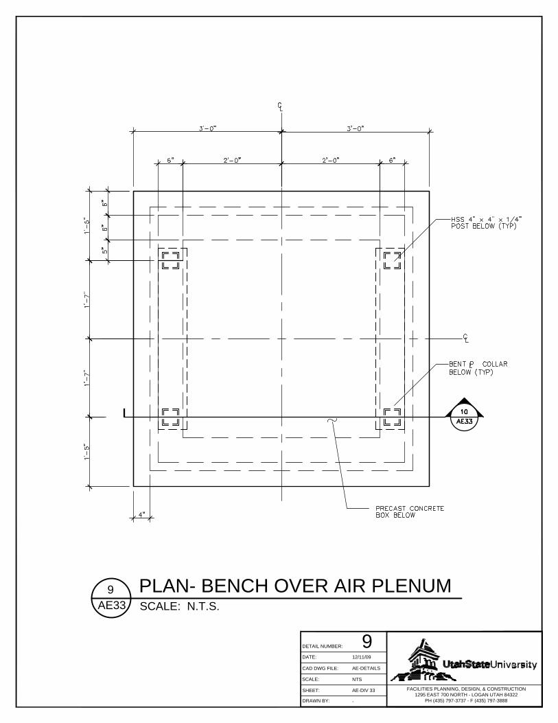
(f) Provide concrete benches with air inlets/outlets to match the existing benches or provide other approved designs by project design architect. See Detail Nos. 9/AE33 & 10/AE33.
M. Building Access:
1. Match the existing tunnel system. 2. Doors by contractor; locks by USU.
N. Miscellaneous:
1. Match the existing tunnel components for the following systems:
(a) Radio Antenna System (b) Grating System (c) Tunnel Penetrations (d) Security System (e) Concrete Walks and Curbs (f) Landscaping
33 08 00 Commissioning of Utilities
A. All utility systems shall be commissioned. Refer to project commissioning requirements.
33 10 00 WATER UTILITIES 33 11 00 Water Distribution Piping
A. Install all undrained water piping with a minimum cover of 5-1/2 feet for
freeze protection.

7 July 2014 USU A/E Design Manual 9
B. Provide water distribution piping, fittings, and accessories from the
following:
Culinary Water: ¾” – 3” Poly service CTS 4” Ductile Iron
C. Minimum diameter for all mainline water piping is 8 inch.
D. Comply with Utah DAR Code R309-500-5 requirements for all water lines.
E. All USU mainline water piping must meet requirements of 33 11 13 and 33 11 19.
33 11 13 Public Water Utility Distribution Piping
A. Install and test water lines according to the latest version of AWWA C600.
B. Disinfect water lines according to the latest version of AWWA C651. 33 11 19 Fire Suppression Water Distribution Piping
A. Provide fire suppression water distribution piping, fittings, and accessories from the following: Fire Suppression: All sizes Ductile Iron
B. Install all fire main piping as per NFPA 24 and thrust blocks per NFPA
Appendix B. C. Install 6” minimum diameter fire main piping and no smaller than the
fire riser. D. Install fire main piping with a minimum cover of 5-1/2’ and wrap all joint
connections. E. Submit a contractor’s material and test certification for underground
piping. F. Test all piping to 1-1/2 times the working pressure with a minimum of
200 psig minimum G. USU authorized representative and USU Fire Marshal must witness
and document all testing and flushing.

7 July 2014 USU A/E Design Manual 10
33 12 00 Water Distribution Equipment
A. Consult with USU representatives for placement of backflow preventers, distribution valves, flow control valves, fire hydrants, pumping stations, meters, and other equipment.
33 12 19 Fire Hydrants
A. Install fire hydrants as per NFPA 24. B. Fire hydrants shall be provided along the required fire apparatus
access roads and adjacent public streets. C. The minimum number of fire hydrants required, spacing, and maximum
distance (street to hydrant) shall be based on appendix C of the IFC. D. Fire hydrant mains shall be no smaller than 8 inches, and shall avoid
dead end situations so that the required fire flow is not compromised. E. Provide approved dry barrel type fire hydrants having two 2-1/2 inch
outlets and one 4-1/2 inch steamer connection, all outlets having NST (National Standard Threads).
F. Provide protection guard posts where fire hydrants are subject to
impact by motor vehicles conforming to section 312 of the IFC. G. See Detail No. 16/AE33 for fire hydrant installation detail.
33 30 00 SANITARY SEWERAGE UTILITIES 33 31 00 Sanitary Sewerage Piping
A. Provide sanitary sewerage piping, fittings, and accessories from the following: Sanitary Sewer: All sizes Cast Iron PVC ABS
B. Vertical Drops: Open vertical drops are not allowed inside manholes and are strongly discouraged at any location. Provide piped vertical riser. Consult with USU personnel to discuss options. See Detail No. 18/AE33 for piped vertical riser detail.
C. Depressed Sewers (inverted siphons): Inverted siphons shall be discussed with USU personnel prior to design.

7 July 2014 USU A/E Design Manual 11
D. Pipe Diameter: Sewer mains and laterals shall be designed to maintain a depth of not more than 0.9 times the internal diameter of the line at peak flows.
E. Velocity: Sewer lines shall be designed to have a minimum velocity of
2 feet per second and a maximum velocity of 10 feet per second.
F. Alignment: Sewer lines shall be designed with uniform grade and alignment between manholes.
G. Manholes: Install manholes at the following conditions:
1. Every change in grade 2. Every change in pipe diameter 3. Every change in alignment 3. Every junction of two or more sewer mains 4. Every building connection (rare exception may be made for 4 inch
service lines; consult with USU personnel) H. Logan City: Consult with USU and Logan City personnel prior to design
sewer connections to confirm that Logan City’s system has adequate capacity. Updates of their sewer system model may be required.
33 40 00 STORM DRAINAGE UTILITIES 33 41 00 Storm Drainage Piping
A. Connect the building storm drainage system to storm water retention sumps located near each building on the central campus.
B. Where sumps are necessary they shall be adequately sized for a 10
year 1 hour storm. Provide a catch basin or a clean-out box at each change in direction or change in grade. Design site drainage, curb, and storm drains to keep water away from buildings and pedestrian walkways. Grates on all catch basins shall have bicycle- safe openings. Surface drains from paved areas shall have oil/water separators prior to discharging into the sumps. Bio filters may be used in lieu of oil/water separators when site conditions permit. Roof drains shall have separate sumps from surface drains.
C. Provide surface water containment site plans to the applicable city in
accordance with EPA rules prior to excavation. D. Connect all surface water to the storm water retention sumps. No
storm water shall be connected to the sanitary sewer system.

7 July 2014 USU A/E Design Manual 12
E. Provide storm drainage piping, fittings, and accessories from the following: Storm Drainage: All sizes Cast Iron
PVC ABS HDPE
33 44 19 Storm Water Treatment
A. Sumps: See Detail No. 14/AE33 for storm drain sumps. B. Catch Basin: All catch basins shall be designed to capture sediments
and floatables and prohibit them from being discharged. See Detail No. 15/AE33 for catch basin detail.
C. Interceptors: Interceptors shall be installed directly upstream of storm
water sumps where required. See Detail No. 17/AE33 for interceptor detail.
33 50 00 FUEL DISTRIBUTION UTILITIES 33 51 00 Natural Gas Distribution
A. The central campus natural gas system is 5 psig used for cooking equipment, laundry facilities, and laboratory gas systems. The central campus natural gas system should not be used for building heating or domestic hot water heating.
B. Use 5 psig pressure for new exterior natural gas systems. C. Use 2 psig or 4 oz. pressure for new building natural gas systems
installed inside of buildings. D. Provide thermoplastic ASTM D2513 exterior gas piping and anode less
risers. E. Natural gas pipe installers shall be Questar Gas certified. F. All natural gas piping shall conform to Questar Gas requirements. G. Install poly pipe with sand bedding for underground installations. All
connections to be fused by Questar certified contractor. H. Provide 30” minimum cover for all gas piping. I. Provide automatic seismic shut-off valves downstream of the gas
meter. See Division 23 for requirements.

7 July 2014 USU A/E Design Manual 13
33 60 00 HYDRONIC AND STEAM ENERGY UTILITIES 33 61 00 Hydronic Distribution
A. Provide direct buried chilled water piping, fittings, and accessories from the following: Chilled Water: All sizes Pre-Insulated PVC
B. Refer to utility tunnel section for chilled water piping requirements in tunnels.
C. Install chilled water piping sloped for drainage and with 5-1/2’ minimum
ground cover.
33 63 00 Steam and Condensate Distribution
A. Provide direct buried steam and condensate piping, fittings, and accessories from the following: Steam: All sizes Schedule 40 seamless black steel (welded) Gilsulate Insulation Condensate: All sizes Schedule 10 stainless steel (TIG welded) Schedule 80 seamless black steel (welded) Gilsulate Insulation
B. Refer to utility tunnel section for steam and condensate piping requirements in tunnels and HVAC section for steam and condensate piping requirements in buildings.
C. Install direct bury steam and condensate piping within a Gilsulate
insulation envelope. D. Install steam and condensate piping with 5-1/2’ minimum ground
cover. 33 70 00 ELECTRICAL UTILITIES
A. Refer to the Electrical AE Manual. 33 80 00 COMMUNICATIONS UTILITIES
A. Refer to the Electrical AE Manual.

7 July 2014 USU A/E Design Manual 14
Revision Log: 7/7/14: Use mastic sealers on manhole rings, use drip legs instead of sloping steam piping, culinary water piping material, piped sewage vertical drop requirements and detail, storm drainage requirements, natural gas piping requirements.
TRENCH WIDTH
PER O.S.H.A.
12" M
IN.
SAWCUT EXISTING PAVEMENTA MIN. OF 1' BEYOND TRENCH
TACK COAT
EXISTING SUBGRADE
UNDISTURBED SOIL
SAND BEDDING MATERIAL
SAND, PVC=4" OR D.I.=2"
MATCH EXISTING ASPHALT EXCEPT4" MIN. AND 4" MIN. ROADBASE
BEDDING AND BACKFILLWHERE NO PAVEMENTEXISTS
12" TOPSOILMATERIAL
MATERIAL PER SOILREPORT
2ND LIFT
1ST LIFT
NOTE:TRENCH SLOPE SHALL BE AS PER O.S.H.A.
12" PITRUN GRAVELCOMPACTED IN 2 LIFTS
MARKING TAPE 18-24"ABOVE LINE
FACILITIES PLANNING, DESIGN, & CONSTRUCTION
1295 EAST 700 NORTH - LOGAN UTAH 84322
PH (435) 797-3737 - F (435) 797-3888
CAD DWG FILE:
DATE:
SHEET:
SCALE:
DRAWN BY:
1DETAIL NUMBER:
12/11/09
AE-DETAILS
NTS
AE-DIV 33
-
UTILITY LINE INSTALLATION1
AE33
SCALE: N.T.S.

CHILLEDWATER
SUPPLY
CHILLEDWATER
RETURN
WATER
CABLE TRAY
10'-0
"
CONDENSATE
STEAM
CABLE TRAY
HIGHPRESSURECONDENSATE
8' MI
N.4' MIN.
REQUIREDCLEARANCE
FACILITIES PLANNING, DESIGN, & CONSTRUCTION
1295 EAST 700 NORTH - LOGAN UTAH 84322
PH (435) 797-3737 - F (435) 797-3888
CAD DWG FILE:
DATE:
SHEET:
SCALE:
DRAWN BY:
2DETAIL NUMBER:
12/11/09
AE-DETAILS
NTS
AE-DIV 33
-
TYPICAL MAIN TUNNEL SECTION2
AE33
SCALE: N.T.S.

CONSTRUCTION JOINT DETAIL
NOT TO SCALETUNNEL WALLS AND BASE SLAB
1" X 3/4" SWELL STOPBY GREENSTREAK
WATERSEAL
1"
SIZED 25% LARGEREVAZOTE 380 E.S.P.
THAN SEAL OPENING
NOT TO SCALEDETAIL
RECESS 1/8"(TYPICAL)
EXPANSIONJOINT FILLER
1"
EXPANSIONJOINT FILLER
BACKING RODFOAM
SEALANT
1/2"
OUTSIDE FACE
INSIDE FACE
1 1/2"
ON THE JOINT MATERIALAND FILLING THE GROOVESTO BOTH SUBSTRATE SURFACESEVA-POX BONDER #1 APPLIED
EXPANSION JOINT DETAILTUNNEL WALLS
NOT TO SCALE NOT TO SCALETUNNEL BASE SLAB & TOP SLAB
EXPANSION JOINT DETAIL
ON THE JOINT MATERIALAND FILLING THE GROOVESTO BOTH SUBSTRATE SURFACESEVA-POX BONDER #1 APPLIED
A
A
A
FACILITIES PLANNING, DESIGN, & CONSTRUCTION
1295 EAST 700 NORTH - LOGAN UTAH 84322
PH (435) 797-3737 - F (435) 797-3888
CAD DWG FILE:
DATE:
SHEET:
SCALE:
DRAWN BY:
3DETAIL NUMBER:
12/11/09
AE-DETAILS
NTS
AE-DIV 33
-
TYPICAL TUNNEL EXPANSION JOINT DETAIL3
AE33
SCALE: N.T.S.

SLOPE 1"
3 1/2"(x1 1/2" DP)TRENCH
SLOPE 1"
2'-0"
1 1/2" (TYP)
TOC EL VARIES
WATERSEAL(TYPICAL)
TYP
14"
10'-0
"10
"VA
RIES
10"SIDEWALK OR PAVEMENT W/
10"10'-0"
WATERPROOFING
AND PROTECTIONBOARD
MEMBRANE
(SYM) TUNNEL
4" BASE COURSE
SUBBASE ORTOPSOIL
WATER SEALSWELL STOP
WATER SEALSWELL STOP
FACILITIES PLANNING, DESIGN, & CONSTRUCTION
1295 EAST 700 NORTH - LOGAN UTAH 84322
PH (435) 797-3737 - F (435) 797-3888
CAD DWG FILE:
DATE:
SHEET:
SCALE:
DRAWN BY:
4DETAIL NUMBER:
12/11/09
AE-DETAILS
NTS
AE-DIV 33
-
TYPICAL MAIN TUNNEL SECTION4
AE33
SCALE: N.T.S.

SLOPE 1"
SOIL BACKFILLSCREENED NATIVE
BRANCH TUNNEL
W/ SUBBASE OR TOPSOILSIDEWALK OR PAVEMENT 8"
WATERSEAL (TYP)
TYP
TOC EL VARIES
9'-0"
AND PROTECTIONMEMBRANEWATERPROOFING
8'-0" 8"
VARI
ES8"
10"
1'-4"
TUNNEL(SYM)
3 1/2"(x1 1/2" DP)TRENCH
BOARD
4" BASE COURSE
WATER SEALSWELL STOP
WATER SEALSWELL STOP
SWELL STOP
FACILITIES PLANNING, DESIGN, & CONSTRUCTION
1295 EAST 700 NORTH - LOGAN UTAH 84322
PH (435) 797-3737 - F (435) 797-3888
CAD DWG FILE:
DATE:
SHEET:
SCALE:
DRAWN BY:
5DETAIL NUMBER:
12/11/09
AE-DETAILS
NTS
AE-DIV 33
-
TYPICAL BRANCH TUNNEL SECTION5
AE33
SCALE: N.T.S.

9'-0"
3'-0"
6'-11"(±
)6"
SAWCUT OPENINGFOR NEW DOOR(2'-6" W x 6'-8" H)
1" EXPANSIONJOINT
EXISTINGFOUNDATION
BRANCH TUNNEL
FLASHING
WATERPROOFING
WATERSEALSWELL SEAL
WATERSEALSWELL SEAL
ASPHALTADHESIVE
BUILDING
1"
FACILITIES PLANNING, DESIGN, & CONSTRUCTION
1295 EAST 700 NORTH - LOGAN UTAH 84322
PH (435) 797-3737 - F (435) 797-3888
CAD DWG FILE:
DATE:
SHEET:
SCALE:
DRAWN BY:
6DETAIL NUMBER:
12/11/09
AE-DETAILS
NTS
AE-DIV 33
-
BRANCH TUNNEL SECTION6
AE33
SCALE: N.T.S.

1'-2"
10'-0
"10
"VA
RIES
8"
4'-10" 6'-10"
10" 4'-0" 6'-0" 10"
WATERSEALSWELL STOP
(TYP)
SIDEWALK 3'-0"X6'-0"ACCESS DOOR
MATERIAL (MIN
)
1'-8"8'-4" SLAB OPENING
5"
TUNNELTOP SLAB
MAIN
TUN
NEL
BRAN
CH T
UNNE
L8"
8'-0"
10"
WATERSEALSWELL STOP
(TYP)
WATERSEALSWELL STOP
(TYP)
FACILITIES PLANNING, DESIGN, & CONSTRUCTION
1295 EAST 700 NORTH - LOGAN UTAH 84322
PH (435) 797-3737 - F (435) 797-3888
CAD DWG FILE:
DATE:
SHEET:
SCALE:
DRAWN BY:
7DETAIL NUMBER:
12/11/09
AE-DETAILS
NTS
AE-DIV 33
-
TUNNEL SECTION7
AE33
SCALE: N.T.S.

FACILITIES PLANNING, DESIGN, & CONSTRUCTION
1295 EAST 700 NORTH - LOGAN UTAH 84322
PH (435) 797-3737 - F (435) 797-3888
CAD DWG FILE:
DATE:
SHEET:
SCALE:
DRAWN BY:
8DETAIL NUMBER:
12/11/09
AE-DETAILS
NTS
AE-DIV 33
-
TUNNEL SECTION8
AE33
SCALE: N.T.S.
FACILITIES PLANNING, DESIGN, & CONSTRUCTION
1295 EAST 700 NORTH - LOGAN UTAH 84322
PH (435) 797-3737 - F (435) 797-3888
CAD DWG FILE:
DATE:
SHEET:
SCALE:
DRAWN BY:
9DETAIL NUMBER:
12/11/09
AE-DETAILS
NTS
AE-DIV 33
-
PLAN- BENCH OVER AIR PLENUM9
AE33
SCALE: N.T.S.

FACILITIES PLANNING, DESIGN, & CONSTRUCTION
1295 EAST 700 NORTH - LOGAN UTAH 84322
PH (435) 797-3737 - F (435) 797-3888
CAD DWG FILE:
DATE:
SHEET:
SCALE:
DRAWN BY:
10DETAIL NUMBER:
12/11/09
AE-DETAILS
NTS
AE-DIV 33
-
SECTION THROUGH BENCH @ AIR PLENUM10
AE33
SCALE: N.T.S.

FACILITIES PLANNING, DESIGN, & CONSTRUCTION
1295 EAST 700 NORTH - LOGAN UTAH 84322
PH (435) 797-3737 - F (435) 797-3888
CAD DWG FILE:
DATE:
SHEET:
SCALE:
DRAWN BY:
11DETAIL NUMBER:
12/11/09
AE-DETAILS
NTS
AE-DIV 33
-
WALL ENTRY DETAIL11
AE33
SCALE: N.T.S.

FACILITIES PLANNING, DESIGN, & CONSTRUCTION
1295 EAST 700 NORTH - LOGAN UTAH 84322
PH (435) 797-3737 - F (435) 797-3888
CAD DWG FILE:
DATE:
SHEET:
SCALE:
DRAWN BY:
12DETAIL NUMBER:
12/11/09
AE-DETAILS
NTS
AE-DIV 33
-
TYPICAL STEAM VALVE DETAIL12
AE33
SCALE: N.T.S.

TRAP
SHA
LL B
E SI
ZED
IN A
CCOR
DANC
E W
ITH
SPEC
IFIC
ATIO
NS.
LINE,
UNL
ESS
INDI
CATE
D OT
HERW
ISE
ON P
IPIN
G AN
D IN
STRU
MENT
DIA
GRAM
S.CO
NNEC
T DI
SCHA
RGE
OF A
LL T
RAPS
TO
NEAR
EST
COND
ENSA
TE R
ETUR
N
STRA
INER
INLE
T AN
D OU
TLET
CON
NECT
IONS
SHA
LL B
E SA
ME S
IZE
AS S
IZE
OFST
RAIN
ER S
HALL
BE
SUIT
ABLE
FOR
MAX
IMUM
DES
IGN
PRES
SURE
AND
TEM
PERA
TURE
.
THIS
DIM
ENSI
ON S
HALL
BE
IDEN
TICA
L FOR
ALL
TRA
P IN
STAL
LATI
ONS.
STEA
M LIN
E 3"
AND
SMA
LLER
: SAM
E AS
DIA
METE
R.DR
IP P
OCKE
T: S
TEAM
LINE
4" A
ND LA
RGER
: 1/2
DIAM
ETER
OF
LINE
SIZE
. USE
3" D
RIP
ON 4"
LINE
.
b) P
IPE
SIZE
SHA
LL B
E SA
ME S
IZE
AS T
RAP
CONN
ECTI
ON,
a) P
IPE
CLAS
S SH
ALL B
E SA
ME C
LASS
AS
STEA
M LIN
E.
REQU
IREM
ENTS
WILL
NOT
PER
MIT
VERT
ICAL
INST
ALLA
TION
.AL
TERN
ATE
HORI
ZONT
AL A
RRAN
GEME
NT O
F BL
OW-O
FF W
HERE
HEA
DROO
M
3/4"
NOTE
10
NOTE
12
NOTE
3
3/4"
NOTE 3
NOTE
16
NOTE
14
NOTE
4
2"6"
NOTE
9
NOTE
13
NOTE
1
NOTE 2 NOTE 5
NOTE
7
T
NOTE
8NO
TE 5
NOTE
17
NOTE
8NO
TE 15
NOTE
61/2"
NOTE 1
STEA
M TR
AP LE
AK S
ENSO
R.
BLOW
-OFF
GLO
BE V
ALVE
.
ISOL
ATIN
G GL
OBE
VALV
E.
17.
16.P
LUG.
CHEC
K VA
LVE
STEA
M LIN
E.
15.
14.
13.
12.b)
PIP
E CL
ASS
TO B
E 15
0.
TRAP
INLE
T CO
NNEC
TION
.
a) E
XTEN
D TO
NEA
REST
TRE
NCH.
PROV
IDE
UNIO
NS O
N ST
EAM
LINE.
BLOW
-OFF
PIP
ING:
11.
10.
9.8.
NOTE
2
NOTE
11
PIPI
NG: P
IPE
SHAL
L BE
CLAS
S 15
0.
PIPI
NG: P
IPE
SHAL
L BE
SAME
AS
STEA
M LIN
E.
UNLE
SS N
OTED
OTH
ERW
ISE.
4. 7.6.5.2. 3.
PIPI
NG:
STEA
M TR
AP N
OTES
:1.
FA
CILIT
IE
S P
LA
NN
IN
G, D
ES
IG
N, &
C
ON
ST
RU
CT
IO
N
1295 E
AS
T 700 N
OR
TH
- LO
GA
N U
TA
H 84322
PH
(435) 797-3737 - F
(435) 797-3888
CA
D D
WG
F
ILE
:
DA
TE
:
SH
EE
T:
SC
ALE
:
DR
AW
N B
Y:
13
DE
TA
IL N
UM
BE
R:
12/11/09
AE
-D
ET
AILS
NT
S
AE
-D
IV
33
-
ST
AN
DA
RD
S
TE
AM
T
RA
P "S
T" D
ET
AIL
13
AE
33
SC
ALE
: N
.T
.S
.

2'-0"
6"
VARI
ES
INLET PIPE. SEEPLAN FOR SIZE.
PLANS FOR SIZE.OVERFLOW PIPE SEE
SEE
PLAN
S10
"
FINISHED GRADE.
6" REINFORCEDCONCRET COVER
36"x 36" REINFORCEDMANHOLE COVER WITH HANDLE.
FILL SPACE AROUND
WASHED GRAVELSUMP WITH 1" -3" Ø
12"
SEE PLANS
PRECASTDURACRETE
ANNULARCONCRETE FOOTING.
FILL BOTTOM
MIRAFI 140 FILTER
GRAVEL AND EARTH.TOP, SIDES, AND
FABRIC BETWEEN
WITH #4 REBAR 6" O.C.
12"WITH GRAVEL
DRY-WELL.
BOTTOM OF SUMP.
EACH WAY 1/2" OFF BOTTOM.
OR CRUSHED STONE.
FACILITIES PLANNING, DESIGN, & CONSTRUCTION
1295 EAST 700 NORTH - LOGAN UTAH 84322
PH (435) 797-3737 - F (435) 797-3888
CAD DWG FILE:
DATE:
SHEET:
SCALE:
DRAWN BY:
14DETAIL NUMBER:
12/11/09
AE-DETAILS
NTS
AE-DIV 33
-
STORM DRAIN SUMP DETAIL14
AE33
SCALE: N.T.S.

ASPHALT
ANGLE IRONANCHORED BY
(SEE
PLA
N)DE
PTH
AS R
EQUI
RED
DURA-CRETE SUMP2'-0"x 2'-0" PRECAST
2" STEEL GRATE
SEE SITE PLANDRAINAGE PIPE
6" MIN. 12" PREFEERED
NOTE: STEEL GRATE AND SUMP TO BE REINFORCED FOR TRUCK TRAFFIC.
PAVING
REBAR ALL AROUND
INSTALL A TEE ORSNOUT ON DRAINAGE PIPE
FACILITIES PLANNING, DESIGN, & CONSTRUCTION
1295 EAST 700 NORTH - LOGAN UTAH 84322
PH (435) 797-3737 - F (435) 797-3888
CAD DWG FILE:
DATE:
SHEET:
SCALE:
DRAWN BY:
15DETAIL NUMBER:
12/11/09
AE-DETAILS
NTS
AE-DIV 33
-
CATCH BASIN DETAIL15
AE33
SCALE: N.T.S.

(2) 2-1/2" HOSE NOZZLES
4-1/2" PUMPER NOZZLE
4'x2'6" CONCRETE PAD
THRUST BLOCK
WATER MAIN
5'-0"
MIN
.
6"
FIRE HYDRANT PER FIREMARSHAL'S REQUIREMENTS
FINISH GRADE
AUXILIARY VALVE
7 CU. FT. OF
THRUST
15"x15"x4"CONCRETE BLOCK
COURSE GRAVEL
AND BOX
3" MIN.6" MAX. 12" MIN.
BLOCK
FACILITIES PLANNING, DESIGN, & CONSTRUCTION
1295 EAST 700 NORTH - LOGAN UTAH 84322
PH (435) 797-3737 - F (435) 797-3888
CAD DWG FILE:
DATE:
SHEET:
SCALE:
DRAWN BY:
16DETAIL NUMBER:
12/11/09
AE-DETAILS
NTS
AE-DIV 33
-
FIRE HYDRANT16
AE33
SCALE: N.T.S.

NOTE
S:
1- G
ENER
AL C
ONDI
TION
S:A-
Plac
e a m
inimu
m of
6-inc
hes o
f free
drain
ing be
dding
mate
rial u
nder
inter
cepto
rB-
Inter
cepto
r to b
e with
in 1/2
-inch
of le
vel in
any d
irecti
on fr
om co
rner
to co
rner
C- B
i-dire
ction
al cle
anou
ts re
quire
d at In
let an
d Outl
etD-
No s
epar
ate sa
mplin
g man
hole
is re
quire
d (Ou
tlet b
affle
meets
requ
ireme
nt of
samp
ling m
anho
le)2-
ACC
ESS
COVE
RS:
A- S
hall b
e 24-
inch d
iamete
r and
stam
ped a
s "SE
WER
"B-
Sha
ll be a
hing
ed st
yle rin
gs an
d cov
ers u
nless
tight
cove
rs ar
e req
uired
C- T
ight c
over
s are
requ
ired w
hen t
he in
terce
ptor is
surro
unde
d by b
uildin
gs on
at le
ast th
ree s
ides
and t
he bu
ilding
s are
with
in 10
0 fee
t or if
the i
nterce
ptor is
loca
ted in
a hig
h tra
ffic ar
ea (U
SU
perso
nnel
will d
eterm
ine re
quire
ment)
.D-
Set
cove
r to w
ithin
1/8-in
ch lo
wer t
han s
urro
undin
g fini
sh gr
ade
E- In
land
scap
ed ar
eas i
nterce
ptor li
d mus
t be 1
2-inc
hes b
elow
finish
ed gr
ade (
i.e. 6
-inch
grad
e ring
and 6
-inch
acce
ss rin
g and
cove
r)F-
Gra
de rin
g use
is lim
ited t
o 12-
inche
s3-
VEN
T LIN
E:A-
Req
uired
only
when
tight
acce
ss co
vers
are u
tilize
dB-
Sha
ll be a
mini
mum
2-inc
h diam
eter p
ipeC-
Sha
ll be s
loped
TO
inter
cepto
rD-
Pen
etrati
on in
to int
erce
ptor m
ust b
e sea
ledE-
Sha
ll be t
ermi
nated
abov
e roo
f of b
uildin
g bein
g ser
viced
by in
terce
ptor
4- IN
LET/
OULE
T PI
PING
:A-
Sha
ll be m
inimu
m 4-
inch d
iamete
rB-
Pen
etrati
on to
be se
aled w
ith a
flexib
le, ca
st-in,
pipe
to st
ructu
re co
nnec
torC-
Inlet
shall
be at
leas
t 1-in
ch hi
gher
than
inlet
to C
ell II
D- O
utlet
shall
be at
leas
t 2-in
ches
lowe
r tha
n Inle
tE-
All j
oints
must
be pr
oper
ly co
nnec
tedF-
Outl
et ba
ffle pi
ping m
ust b
e anc
hore
d to i
nterce
ptor w
all in
at le
ast o
ne lo
catio
n5-
BAF
FLE
WAL
L:A-
Des
ign sh
own i
s not
the on
ly all
owab
le de
sign
B- A
ny co
nfigu
ratio
n tha
t mee
ts the
inten
t of th
e des
ign is
acce
ptable
C- In
tent is
to tr
ansfe
r liqu
id fro
m Ce
ll I to
Cell
II wh
ile el
imina
ting "
shor
t circ
uits"
6"
9"
3"3" 6"
INLE
T
6"
6"
9"
VENT
LINE
(SEE
NOT
E)
BI-D
IREC
TION
AL C
LEAN
OUT
(SEE
NOT
E)
ACCE
SS C
OVER
S(S
EE N
OTE)
OUTL
ET
INLE
T(S
EE N
OTE)
ANCH
OR
OUTL
ET(S
EE N
OTE)
FA
CILIT
IE
S P
LA
NN
IN
G, D
ES
IG
N, &
C
ON
ST
RU
CT
IO
N
1295 E
AS
T 700 N
OR
TH
- LO
GA
N U
TA
H 84322
PH
(435) 797-3737 - F
(435) 797-3888
CA
D D
WG
F
ILE
:
DA
TE
:
SH
EE
T:
SC
ALE
:
DR
AW
N B
Y:
17
DE
TA
IL N
UM
BE
R:
12/11/09
AE
-D
ET
AILS
NT
S
AE
-D
IV
33
-
GR
EA
SE
IN
TE
RC
EP
TO
R17
AE
33
SC
ALE
: N
.T
.S
.


![March 23, 2016 TFF Project #14114purchasing.gcsnc.com/RFQAttachments/GCS-WGHSPE... · Roofing [7 pages] - Revised Specification Section 33 10 00 (Water Utilities) [14 pages] ... H.M](https://img.dokumen.tips/doc/110x75/5f27819f0b8dc71fed744383/march-23-2016-tff-project-roofing-7-pages-revised-specification-section-33.jpg)