Embed Size (px)
Citation preview
UNIVERSITY OF NORTH DAKOTA – DESIGN STANDARDS page 1
Print Date: 11/4/2016
DIVISION 26 - ELECTRICAL
26 0501 MINOR ELECTRICAL DEMOLITION
A. Coordinate utility service outages with the UND Electrical Department.
B. Verify the abandoned wiring and equipment serve only abandoned facilities.
C. Provide temporary wiring and connections to maintain existing systems in service during
construction. When work must be performed on energized equipment or circuits, use personnel
experienced in such operations and follow the safe working practice requirements of NFPA 70E.
D. Demolition and extension:
1. Remove, relocate, and extend existing installations to accommodate new construction.
2. Remove abandoned wiring to source of supply.
3. Provide revised typed circuit directory in panelboards that have circuits removed.
4. Remove exposed abandoned conduit and abandoned conduit above accessible ceiling
finishes. Cut conduit flush with walls and floors, and patch surfaces.
5. Disconnect abandoned outlets and remove devices. Remove abandoned outlets if conduit
and wiring serving them is abandoned and removed. Provide blank cover for abandoned
outlets which are not removed.
6. Disconnect and remove abandoned panelboards and distribution equipment.
7. Disconnect and remove electrical devices and equipment serving utilization equipment
that has been removed.
8. Disconnect and remove abandoned luminaires. Remove brackets, stems, hangers, and
other accessories.
E. PCB Ballast Handling:
1. Generally, all high power factor fluorescent light ballasts manufactured before 1978 and
some HID ballasts contain polychlorinated biphenyl (PCB) compounds in their capacitors.
The Contractor shall inspect all ballasts in all light fixtures and take the actions described
below.
a. The disposal of all ballasts labeled as “NON-PCBs” or NO PCBs” shall become the
responsibility of the Contractor. If the PCB content is not stated on the ballast label,
the ballast shall be handled as a PCB ballast.
F. Lamp and PCB Ballast Disposal:
UNIVERSITY OF NORTH DAKOTA – DESIGN STANDARDS page 2
Print Date: 11/4/2016
1. All lamps (fluorescent, incandescent, and HID) contain mercury and/or lead (in the base)
as well as other heavy metals and compounds which are regulated by the EPA and DNR
during the disposal process. As a result, regulations have been issued covering the
handling and disposal of all lamps.
26 0513 MEDIUM-VOLTAGE CABLES
A. Preferred manufacturer The Okonite Company
B. Cable Type: Type MV 105.
C. Conductor: Copper.
D. Conductor Insulation: Ethylene-propylene rubber. Voltage Rating: 15 kV.
E. Insulation Thickness: 220 mils with a 133 percent insulation level.
F. Shielding: 1/3 neutral solid copper wires, helically applied over semiconducting insulation
shield.
G. Load-Break Cable Terminators: Elbow-type units with 200-A-load make/break and continuous-
current rating; coordinated with insulation diameter, conductor size, and material of cable being
terminated. Include test point on terminator body that is capacitance coupled.
H. Connectors to be as manufactured by Cooper model T-OP II
I. High voltage underground lines shall have a yellow or red warning tape and be buried a minimum
of 30 inches deep covered with six inches of sand and concrete slurry.
26 0519 LOW-VOLTAGE ELECTRICAL POWER CONDUCTORS AND CABLES
26 0520 UNDER CARPET CABLES
A. Subject to review with owner
26 0526 GROUNDING AND BONDING FOR ELECTRICAL SYSTEMS
A. Accurately record actual locations of grounding electrodes.
B. Rod Electrode:
1. Material: Copper-clad steel.
2. Diameter: 3/4 inch.
UNIVERSITY OF NORTH DAKOTA – DESIGN STANDARDS page 3
Print Date: 11/4/2016
3. Length: 8 feet.
C. Exothermic Connections: Manufacturers: Caldwell
D. Installation:
1. Provide grounding electrode conductor and connect to reinforcing steel in foundation
footing.
2. Bond together metal siding not attached to grounded structure; bond to ground.
3. Equipment Grounding Conductors: Provide separate, insulated conductor within each
feeder circuit and branch circuit raceway. Terminate each end on suitable lug, bus, or
bushing.
4. Bonding: All interior metal water, sewer and gas piping shall be bonded together and
connected to the grounding electrode conductor. Connect a bonding conductor from the
structural steel system to the grounding electrode conductor.
5. Resistance to ground and between multiple ground electrodes shall be measured and
recorded.
UNIVERSITY OF NORTH DAKOTA – DESIGN STANDARDS page 4
Print Date: 11/4/2016
26 0529 HANGERS AND SUPPORTS FOR ELECTRICAL SYSTEMS
A. Steel Slotted Support Systems – galvanized steel.
B. Anchors and Fasteners:
1. Concrete Structural Elements: Use precast insert system, expansion anchors and preset
inserts.
2. Steel Structural Elements: Use beam clamps, spring steel clips steel ramset fasteners, and
welded fasteners.
3. Concrete Surfaces: Use self-drilling anchors and expansion anchors.
4. Hollow Masonry, Plaster, and Gypsum Board Partitions: Use toggle bolts and hollow wall
fasteners.
5. Solid Masonry Walls: Use expansion anchors and preset inserts.
6. Sheet Metal: Use sheet metal screws.
7. Wood Elements: Use wood screws.
8. Plastic anchors are unacceptable in concrete or block walls. Properly applied nylon tap ins
are acceptable.
C. Installation:
1. Do not fasten supports to pipes, ducts, mechanical equipment, and conduit.
2. Do not use spring steel clips and clamps.
3. Do not use powder-actuated anchors.
4. Install surface-mounted cabinets and panelboards with minimum of four anchors.
5. In wet and damp locations, use steel channel supports to stand cabinets and panelboards
one inch off wall.
6. Provide a 3/4 inch plywood backboard for all communication and electrical closets. Cover
with two coats of gray paint.
7. Mount enclosures so that at least 1/4 inch air space is provided between the enclosure
and the supporting surface.
26 0534 CONDUIT

UNIVERSITY OF NORTH DAKOTA – DESIGN STANDARDS page 5
Print Date: 11/4/2016
A. A half inch (1/2”) conduit shall be run from the top of entrance frames (both hollow metal frames
and aluminum frames) to above the finished ceiling for door frames for electronically access
controlled doors.
B. All spare and empty conduits to be used in the future shall be identified on termination end of
each conduit for area served.
C. Electrical Metal Tubing (EMT): Set screw fittings are acceptable. Compression fittings are to be
used where required.
D. Electrical Metal Tubing (EMT): Shall not be used in areas where subject to corrosive conditions
unless specifically indicated, and then only a type with a bonded polyvinyl coating.
26 0535 SURFACE RACEWAYS
A. Wireway shall be galvanized sheet steel provided with full length hinged covers and coordinated
fittings including tees, collars, elbows and a closing plate required for a completely enclosed
raceway. Sheet metal parts shall be coated with a rust inhibitor and finished with baked enamel.
Hardware shall be plated to prevent corrosion.
26 0536 CABLE TRAYS FOR ELECTRICAL SYSTEMS
26 0537 BOXES
A. Provide a junction box above dropped ceilings in outlet home run circuit for individual rooms.
B. Provide a junction box above dropped ceilings in individual rooms if multiple rooms exist on one
run for future wiring.
C. Install pull boxes and junction boxes above accessible ceilings and in unfinished areas only.
D. Inaccessible ceiling areas: Install outlet and junction boxes no more than 6 inches from ceiling
access panel or from removable recessed luminaire.
E. All home run junction boxes shall be legibly identified on cover with panel and circuit number.
F. Floor Boxes: Fully adjustable, concrete tight. Formed steel. Rectangular.
26 0540 UNDERFLOOR DUCTS
A. Duct shall be 14 gauge steel with a corrosion resistant finish. System shall include all junction
boxes, couplings, conduit adapters, elbows, crossunders, offsets and service fittings for a
complete system.
UNIVERSITY OF NORTH DAKOTA – DESIGN STANDARDS page 6
Print Date: 11/4/2016
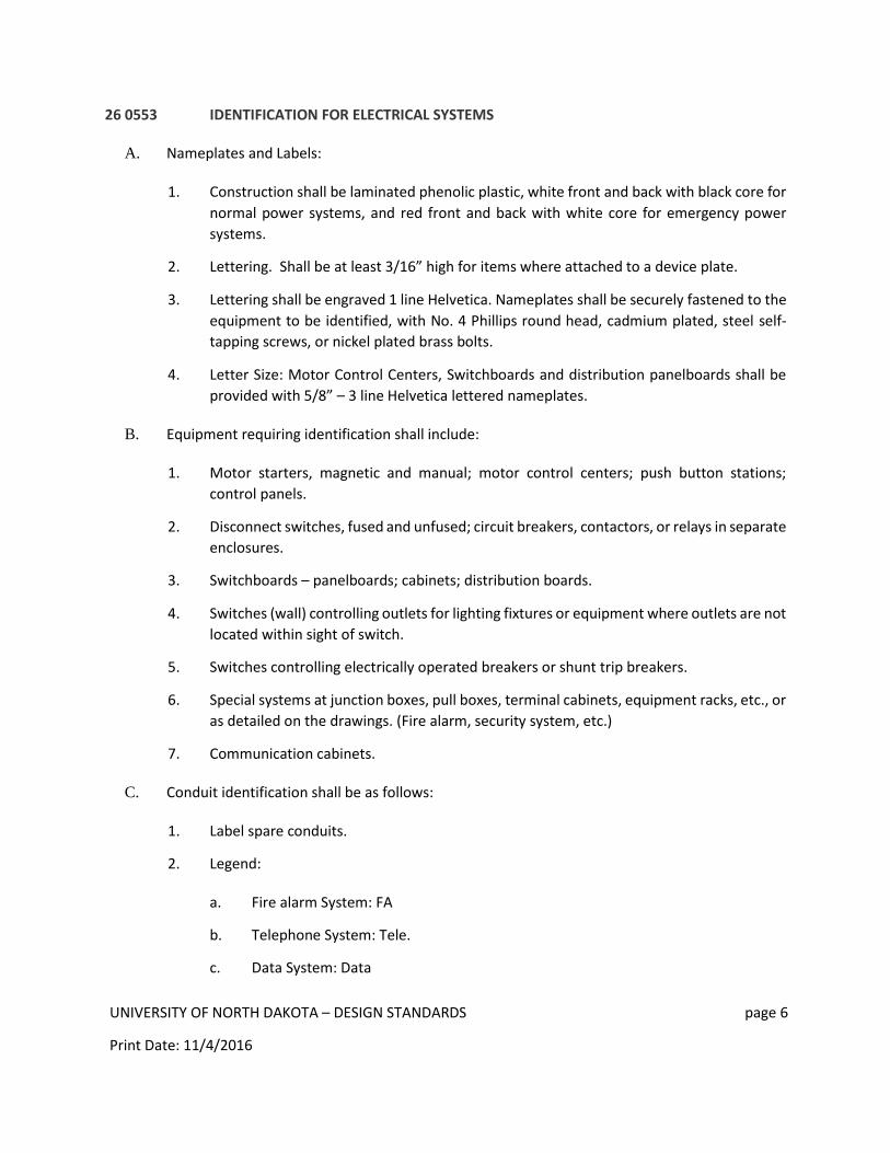
26 0553 IDENTIFICATION FOR ELECTRICAL SYSTEMS
A. Nameplates and Labels:
1. Construction shall be laminated phenolic plastic, white front and back with black core for
normal power systems, and red front and back with white core for emergency power
systems.
2. Lettering. Shall be at least 3/16” high for items where attached to a device plate.
3. Lettering shall be engraved 1 line Helvetica. Nameplates shall be securely fastened to the
equipment to be identified, with No. 4 Phillips round head, cadmium plated, steel self-
tapping screws, or nickel plated brass bolts.
4. Letter Size: Motor Control Centers, Switchboards and distribution panelboards shall be
provided with 5/8” – 3 line Helvetica lettered nameplates.
B. Equipment requiring identification shall include:
1. Motor starters, magnetic and manual; motor control centers; push button stations;
control panels.
2. Disconnect switches, fused and unfused; circuit breakers, contactors, or relays in separate
enclosures.
3. Switchboards – panelboards; cabinets; distribution boards.
4. Switches (wall) controlling outlets for lighting fixtures or equipment where outlets are not
located within sight of switch.
5. Switches controlling electrically operated breakers or shunt trip breakers.
6. Special systems at junction boxes, pull boxes, terminal cabinets, equipment racks, etc., or
as detailed on the drawings. (Fire alarm, security system, etc.)
7. Communication cabinets.
C. Conduit identification shall be as follows:
1. Label spare conduits.
2. Legend:
a. Fire alarm System: FA
b. Telephone System: Tele.
c. Data System: Data
UNIVERSITY OF NORTH DAKOTA – DESIGN STANDARDS page 7
Print Date: 11/4/2016
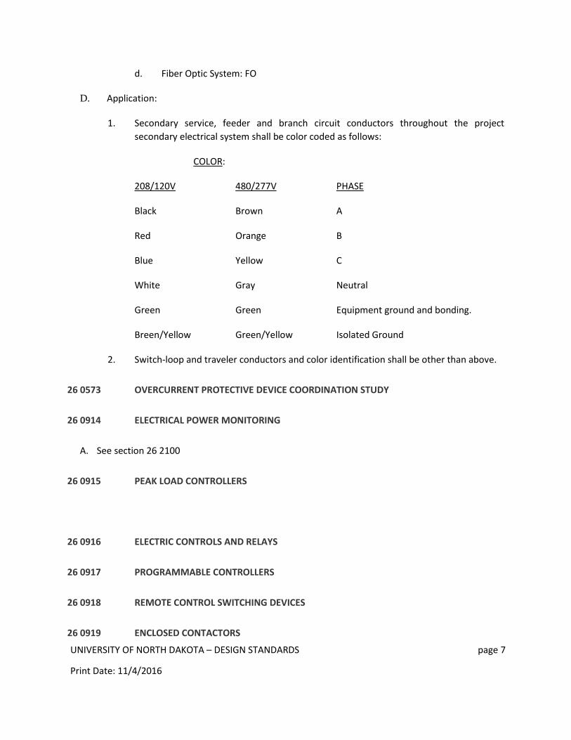
d. Fiber Optic System: FO
D. Application:
1. Secondary service, feeder and branch circuit conductors throughout the project
secondary electrical system shall be color coded as follows:
COLOR:
208/120V 480/277V PHASE
Black Brown A
Red Orange B
Blue Yellow C
White Gray Neutral
Green Green Equipment ground and bonding.
Breen/Yellow Green/Yellow Isolated Ground
2. Switch-loop and traveler conductors and color identification shall be other than above.
26 0573 OVERCURRENT PROTECTIVE DEVICE COORDINATION STUDY
26 0914 ELECTRICAL POWER MONITORING
A. See section 26 2100
26 0915 PEAK LOAD CONTROLLERS
26 0916 ELECTRIC CONTROLS AND RELAYS
26 0917 PROGRAMMABLE CONTROLLERS
26 0918 REMOTE CONTROL SWITCHING DEVICES
26 0919 ENCLOSED CONTACTORS

UNIVERSITY OF NORTH DAKOTA – DESIGN STANDARDS page 8
Print Date: 11/4/2016
26 0923 LIGHTING CONTROL DEVICES
A. SPST motion control devices shall be passive infrared and ultrasonic types.
B. Ceiling motion control devices shall be passive infrared types suitable for use with relay
controlled lighting. Sensors shall be flush mounted in the ceilings. All control wiring shall be in
raceway.
C. Use consideration for light level sensors and daylight controls where natural light can reduce
artificial lighting requirements by owner approval.
D. Refer to ASHRAE 90.1 Lighting Control Standards
26 0924 LIGHTING CONTROLS – WATTSTOPPER
A. Low-voltage sensors with relays to control lights.
26 0943 NETWORK LIGHTING CONTROLS – CRESTRON
26 1116 SECONDARY UNIT SUBSTATIONS
26 1200 MEDIUM-VOLTAGE TRANSFORMERS
A. Subject to review by the Engineer with the Owner.
B. Medium-voltage transformers shall be Cooper.
C. Accessories:
1. One inch drain valve with sampling device.
2. Dial type thermometer.
3. Liquid level gage.
4. Two welded ground lug attachment points.
5. Pressure vacuum gage.
6. Provision for securing access doors in open position.
7. Pressure relief device, self-sealing with indicator.
8. Bay-O-net oil drip tray for each fuse.
9. One line electrical diagram stenciled in clear view when HV door is open.
UNIVERSITY OF NORTH DAKOTA – DESIGN STANDARDS page 9
Print Date: 11/4/2016
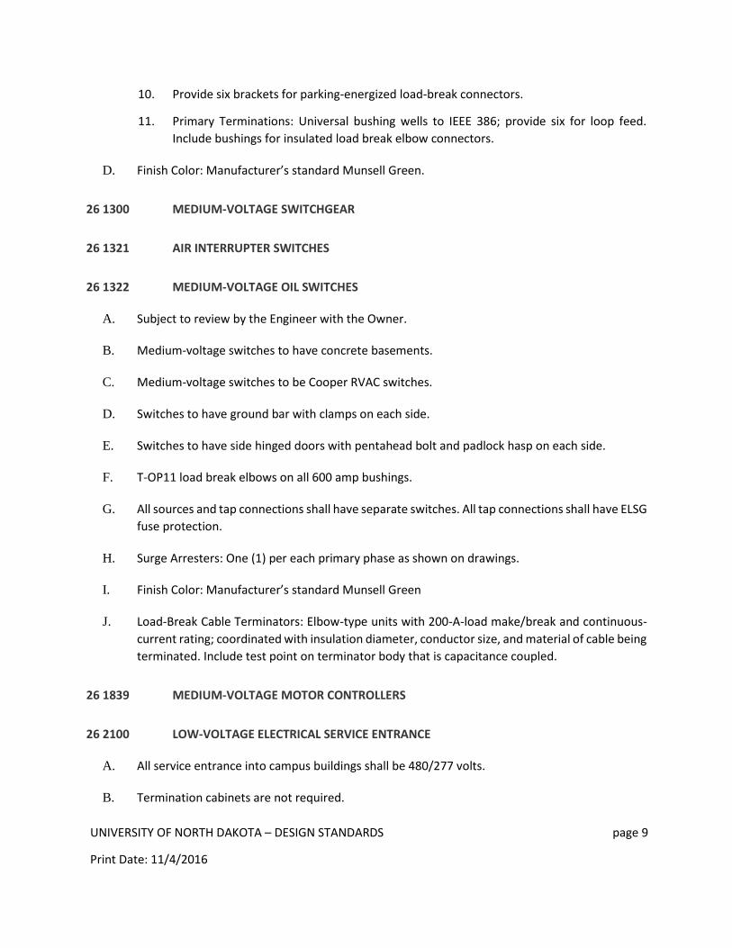
10. Provide six brackets for parking-energized load-break connectors.
11. Primary Terminations: Universal bushing wells to IEEE 386; provide six for loop feed.
Include bushings for insulated load break elbow connectors.
D. Finish Color: Manufacturer’s standard Munsell Green.
26 1300 MEDIUM-VOLTAGE SWITCHGEAR
26 1321 AIR INTERRUPTER SWITCHES
26 1322 MEDIUM-VOLTAGE OIL SWITCHES
A. Subject to review by the Engineer with the Owner.
B. Medium-voltage switches to have concrete basements.
C. Medium-voltage switches to be Cooper RVAC switches.
D. Switches to have ground bar with clamps on each side.
E. Switches to have side hinged doors with pentahead bolt and padlock hasp on each side.
F. T-OP11 load break elbows on all 600 amp bushings.
G. All sources and tap connections shall have separate switches. All tap connections shall have ELSG
fuse protection.
H. Surge Arresters: One (1) per each primary phase as shown on drawings.
I. Finish Color: Manufacturer’s standard Munsell Green
J. Load-Break Cable Terminators: Elbow-type units with 200-A-load make/break and continuous-
current rating; coordinated with insulation diameter, conductor size, and material of cable being
terminated. Include test point on terminator body that is capacitance coupled.
26 1839 MEDIUM-VOLTAGE MOTOR CONTROLLERS
26 2100 LOW-VOLTAGE ELECTRICAL SERVICE ENTRANCE
A. All service entrance into campus buildings shall be 480/277 volts.
B. Termination cabinets are not required.
UNIVERSITY OF NORTH DAKOTA – DESIGN STANDARDS page 10
Print Date: 11/4/2016
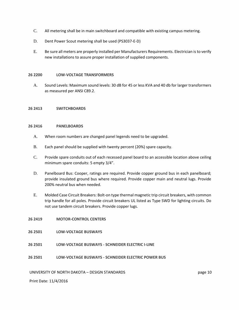
C. All metering shall be in main switchboard and compatible with existing campus metering.
D. Dent Power Scout metering shall be used (PS3037-E-D)
E. Be sure all meters are properly installed per Manufacturers Requirements. Electrician is to verify
new installations to assure proper installation of supplied components.
26 2200 LOW-VOLTAGE TRANSFORMERS
A. Sound Levels: Maximum sound levels: 30 dB for 45 or less KVA and 40 db for larger transformers
as measured per ANSI C89.2.
26 2413 SWITCHBOARDS
26 2416 PANELBOARDS
A. When room numbers are changed panel legends need to be upgraded.
B. Each panel should be supplied with twenty percent (20%) spare capacity.
C. Provide spare conduits out of each recessed panel board to an accessible location above ceiling
minimum spare conduits: 5 empty 3/4”.
D. Panelboard Bus: Cooper, ratings are required. Provide copper ground bus in each panelboard;
provide insulated ground bus where required. Provide copper main and neutral lugs. Provide
200% neutral bus when needed.
E. Molded Case Circuit Breakers: Bolt-on type thermal magnetic trip circuit breakers, with common
trip handle for all poles. Provide circuit breakers UL listed as Type SWD for lighting circuits. Do
not use tandem circuit breakers. Provide copper lugs.
26 2419 MOTOR-CONTROL CENTERS
26 2501 LOW-VOLTAGE BUSWAYS
26 2501 LOW-VOLTAGE BUSWAYS - SCHNEIDER ELECTRIC I-LINE
26 2501 LOW-VOLTAGE BUSWAYS - SCHNEIDER ELECTRIC POWER BUS
UNIVERSITY OF NORTH DAKOTA – DESIGN STANDARDS page 11
Print Date: 11/4/2016
26 2600 POWER DISTRIBUTION UNITS
26 2717 EQUIPMENT WIRING
A. Make conduit connections to equipment using flexible conduit. Use liquid tight flexible conduit
with watertight connectors in damp or wet locations.
B. Make wiring connections using wire and cable with insulation suitable for temperatures
encountered in heat producing equipment.
C. Provide receptacle outlet where connection with attachment plug is required. Provide cord and
cap where field – supplied attachment plug is required.
D. Provide suitable strain-relief clamps and fittings for cord connections at outlet boxes and
equipment connection boxes.
E. Coolers and Freezers: Cut and seal conduit openings in freezer and cooler walls, floor, and
ceilings.
F. Provide air tight seals in and around conduits and busway between inside and outside areas and
in walk-in coolers and freezers.
G. All conductor connections to mechanical equipment shall be copper conductors.
H. MC Cable shall not be excessive in length. No coiling of cable.
26 2723 INDOOR SERVICE POLES
26 2726 WIRING DEVICES
A. Furnish at least 120-volt duplex outlet on each wall in each classroom and office and every 25
feet in corridors, and one outlet on each level in the stair towers.
B. Provide outside receptacle within 3 feet of downspout for heat tape.
C. Dual USB charging receptacle outlet to be as manufactured by Leviton model Power 2U or equal.
D. Provide receptacle outlets in equipment rooms for maintenance.
26 2813 FUSES
A. Fuses subject to review by the Owner.
1. Main disconnect over 600 amps. Shall be class L – Current limiting type.

UNIVERSITY OF NORTH DAKOTA – DESIGN STANDARDS page 12
Print Date: 11/4/2016
2. Main disconnect under 600 amps. Shall be Class RK-1 – Current limiting with rejection
features.
3. Feeders to panels equipped with 10,000 A.I.C. circuit breakers.
a. Up to 150 amps – Class RK-5.
b. 175 amps through 600 amps – Class RK-1.
4. Feeders to power panels, motor control centers or transformers up to 600 amps. Class
Rk-5.
5. Motors served from Fusible control centers, power panels or individually shall be
protected by dual-elements fuses sized at 125% of actual nameplate rating.
a. 100 amps or less – Class Rk-5.
b. Over 100 amps – Glass RK-5.
26 2817 ENCLOSED CIRCUIT BREAKERS
26 2818 ENCLOSED SWITCHES
26 2913 ENCLOSED CONTROLLERS
26 2923 VARIABLE-FREQUENCY MOTOR CONTROLLERS
A. The frequency drives shall be ABB, Allen Bradley or Square D.
B. Installed VFDs must be capable to be bypassed in case of drive failure so the equipment can be
run without the drive.
C. The drive fault must be setup to be reset from the front-end automation system.
D. VFDs shall be configured to restart automatically after a power outage/bump or after a building
fire alarm has returned to normal.
E. VFDs are to be capable of BAC net MS/TP. Monitored and controlled points are listed in the
Facilities Management standard controls specification.
F. Provide monitoring of VFD fault, start/stop, status, alarm and percentage of operation for each
VFD.
G. Install VFD close to motor installation. Do not go over 50 feet for motor lead length.
UNIVERSITY OF NORTH DAKOTA – DESIGN STANDARDS page 13
Print Date: 11/4/2016
H. Install an equipment grounding conductor throughout the VFD circuit. Provide a dedicated
circuit for each VFD.
I. Provide a VFD stand-alone installation. No gutter or wiring is to be common to several VFD’s.
J. Install line, load, and control conductors in three separate raceways.
K. Automation controls should not be mounted inside VFD’s.
26 3100 PHOTOVOLTAIC COLLECTORS
26 3213 ENGINE GENERATORS
A. Subject to review by the Engineer with the Owner.
B. Install separate emergency lighting panel for all exit lights, fire alarm circuits, stairwell lights, and
mechanical equipment spaces.
C. Self-powered units or auxiliary power source are necessary.
D. Generator (natural gas preferred) for life safety, condensate pumps, sump pumps, building
automation and heating pumps.
E. Generator manufacturer must have service within 1 hour of location.
F. Emergency generators do not require programmable exerciser.
G. Power quality measures should be taken to protect equipment. It is Facilities’ recommendation
to use UPSs, power conditioners and/or generator backup systems for all critical equipment and
critical building systems where the department needs to maintain consistency with those
systems or where necessary to protect equipment.
H. Non resettable hour meter
I. All generators shall meet the most correct emissions standards and regulations including but not
limited to 40CFR63 subpart zzzz
26 3229 ROTARY CONVERTERS
26 3233 ROTARY UNINTERRUPTIBLE POWER UNITS
26 3305 BATTERY EMERGENCY POWER SUPPLY
UNIVERSITY OF NORTH DAKOTA – DESIGN STANDARDS page 14
Print Date: 11/4/2016
26 3353 STATIC UNINTERRUPTIBLE POWER SUPPLY
26 3513 LOW-VOLTAGE POWER FACTOR CORRECTION CAPACITORS
26 3600 TRANSFER SWITCHES
26 4113 LIGHTNING PROTECTION FOR STRUCTURES
26 4200 CATHODIC PROTECTION
A. Cathodic protection shall be installed to protect the steam distribution system from corrosion.
26 4300 SURGE PROTECTIVE DEVICES
26 5013 LUMINAIRE SCHEDULE
26 5100 INTERIOR LIGHTING
A. Refer to 90.1 Lighting Control Standards
B. Interior light shall be mounted so the lamp can be replaced from a ten-foot stepladder. Fixtures
that require special equipment, scaffolds, or other paraphernalia to re-lamp or service are to be
kept to a minimum.
C. Minimum lighting used only for decorative purposes.
D. Energy efficient lighting to be installed.
E. All fixtures to be LED 4100K.
F. Lighting controlled by occupancy sensors wherever functionally feasible. The room lighting and
HVAC controls are to work off the same occupancy sensor.
G. Occupancy sensors to control lights in offices, corridors and bathrooms. Lighting should not be
shut off in stairwells. Stairwells to dim on unoccupied status. Labs, classrooms, lecture bowls
and auditoriums to have light switches.
H. Provide adequate light in all equipment rooms.
I. Refer to ASHRAE 90.1 Lighting Control Standards

UNIVERSITY OF NORTH DAKOTA – DESIGN STANDARDS page 15
Print Date: 11/4/2016
26 5113 LUMINAIRES, BALLASTS, AND DRIVERS
A. Consider dimmable drivers for LED fixtures
26 5537 OBSTRUCTION AND LANDING LIGHTS
26 5561 THEATRICAL LIGHTING
26 5600 EXTERIOR LIGHTING
A. Refer to ASHRAE 90.1 Lighting Control Standards
B. Parking Lot and Street Lighting: Use LED fixtures for outdoor lighting with photoelectric cells on-
off control with override switch for maintenance. Fixtures are to match existing fixtures as
approved by owner.
C. Walkway lighting shall be LED fixtures with photoelectric cell on-off control.